

Page 1

i
Software Manual
I626-E-09
TMflow
Original Instruction
Page 2

This Manual contains information of the Techman Robot product series (hereinafter referred to as the TM
Robot). The information contained herein is the property of Techman Robot Inc. (hereinafter referred to as
the Corporation). No part of this publication may be reproduced or copied in any way, shape or form without
prior authorization from the Corporation. No information contained herein shall be considered an offer or
commitment. It may be subject to change without notice. This Manual will be reviewed periodically. The
Corporation will not be liable for any error or omission.
logo is registered trademark of TECHMAN ROBOT INC. in Taiwan and other countries and the
company reserves the ownership of this manual and its copy and its copyrights.
Software Manual TMflow Software version: 1.82
Page 3
3
Contents
Revision History Table ................................................................................................................................ 20
1. General................................................................................................................................................... 21
Overview ....................................................................................................................................... 21
Warning and Caution Symbols ....................................................................................................... 21
Safety Precautions ........................................................................................................................ 22
Validation and Responsibility ......................................................................................................... 23
Limitation of Liability ...................................................................................................................... 23
Functional Note Symbol ................................................................................................................. 23
2. Start up and Activation ............................................................................................................................ 24
Overview ....................................................................................................................................... 24
Start Up ......................................................................................................................................... 24
Plug in the Power .................................................................................................................... 24
Start up from Packing Pose ..................................................................................................... 24
Standard Start Up ................................................................................................................... 28
TM Robot HMI TMflow Operation ............................................................................................ 29
Local Operation Method ................................................................................................... 30
Wireless Access Point Connection Method ....................................................................... 30
Wired Network Connection Method .................................................................................. 31
3. Safety Settings ....................................................................................................................................... 33
Overview ....................................................................................................................................... 33
Safety Permission Settings ............................................................................................................ 33
Safety Setting ................................................................................................................................ 33
Performance Safety Settings ................................................................................................... 34
Human – Machine Safety Settings .......................................................................................... 35
Safety IO Settings ................................................................................................................... 38
Resume Setting of User Connected External Safeguard Input Port .................................. 39
Resume Setting of User Connected External Safeguard Input Port for Human - Machine
Safety Settings ............................................................................................................................. 39
Safeguard Port Setting for the Hardware Version prior to 2.00 (inclusive) ......................... 40
Enabling Device Setting (HW 3.2 or newer exclusive) ...................................................... 40
4. Start Your First Project ............................................................................................................................ 44
Software Manual TMflow Software version: 1.82
Cartesian Limit A & B .............................................................................................................. 41
Project Speed Adjustment Setting ........................................................................................... 41
Switch between Modes ........................................................................................................... 42
Overview ....................................................................................................................................... 44
Page 4
4
Initial Setting .................................................................................................................................. 44
M/A Mode and FreeBot .................................................................................................................. 44
Build and Run Your First Project .................................................................................................... 46
Shutdown ...................................................................................................................................... 49
5. Operation Interface ................................................................................................................................. 51
Overview ....................................................................................................................................... 51
Login/Logout .................................................................................................................................. 51
Connection .................................................................................................................................... 52
Local Connection .................................................................................................................... 52
Remote Connection ................................................................................................................ 52
View .............................................................................................................................................. 53
Display Board .......................................................................................................................... 53
Flow ........................................................................................................................................ 55
IO ............................................................................................................................................ 56
Simulator ................................................................................................................................. 56
Status ...................................................................................................................................... 57
Vision Viewer .......................................................................................................................... 57
Run Setting .................................................................................................................................... 58
Project ........................................................................................................................................... 59
Project Editing Toolbar ............................................................................................................ 60
Create New Project ........................................................................................................... 60
Save Project ..................................................................................................................... 61
Open Project..................................................................................................................... 61
Step Run .......................................................................................................................... 62
Point Manager .................................................................................................................. 63
Base Manager .................................................................................................................. 65
Controller .......................................................................................................................... 66
Variables ........................................................................................................................... 70
EditBlock .......................................................................................................................... 70
Current Base and Base List ............................................................................................ 71
Current TCP and TCP List .............................................................................................. 71
Display Manager ............................................................................................................. 72
Node Menu and Flow Editing Area .......................................................................................... 73
Project Function Menu ............................................................................................................ 74
Search Function ............................................................................................................... 75
Operation Space ............................................................................................................... 76
Software Manual TMflow Software version: 1.82
Page 5

5
Modbus Device ................................................................................................................. 76
Set IO while Project Error ................................................................................................. 76
Set IO while Project Stop .................................................................................................. 76
Stop Watch ....................................................................................................................... 76
View.................................................................................................................................. 77
F/T Sensor ........................................................................................................................ 77
Serial Port ......................................................................................................................... 78
Path Generate ................................................................................................................ 79
Joint Loading .................................................................................................................. 80
Network Device .............................................................................................................. 80
Robot Setting ................................................................................................................................. 81
Wizard ..................................................................................................................................... 81
Vision Setting .......................................................................................................................... 81
TCP ......................................................................................................................................... 81
IO Setup .................................................................................................................................. 81
Safety ...................................................................................................................................... 82
Controller ................................................................................................................................ 82
Speech .................................................................................................................................... 82
End Button .............................................................................................................................. 83
Component ............................................................................................................................. 84
Operation Space ................................................................................................................... 84
Command .............................................................................................................................. 84
Connection ............................................................................................................................ 84
Posture Setting...................................................................................................................... 85
Global Variables .................................................................................................................... 86
Text File Manager .................................................................................................................. 86
TMmanager ........................................................................................................................... 86
Motion Setting ....................................................................................................................... 86
System Setting .............................................................................................................................. 87
Language ................................................................................................................................ 88
System Update ....................................................................................................................... 88
Group ...................................................................................................................................... 89
User Account ........................................................................................................................... 90
Network Setting ....................................................................................................................... 90
Import/Export .......................................................................................................................... 91
Date Time................................................................................................................................ 93
Software Manual TMflow Software version: 1.82
Page 6
6
Administrator Setting ............................................................................................................... 93
Network Service ...................................................................................................................... 94
Backup\Restore..................................................................................................................... 95
Input/Display Devices ............................................................................................................ 96
Pop-out Keyboard ........................................................................................................... 96
Input Devices (HW 3.2 or newer exclusive) ..................................................................... 97
Auto Remote Mode ............................................................................................................... 97
Hard Disk Space Analysis ..................................................................................................... 98
6. Point and Base ..................................................................................................................................... 100
Overview ..................................................................................................................................... 100
Base and Right-hand Rule ........................................................................................................... 101
Right-hand Rule .................................................................................................................... 101
Types of Base ....................................................................................................................... 101
Robot Base ..................................................................................................................... 101
Vision Base ..................................................................................................................... 102
Custom Base .................................................................................................................. 102
Tool Coordinate .............................................................................................................. 103
Point Parameter ........................................................................................................................... 103
Base Shift.............................................................................................................................. 104
Tool Shift ............................................................................................................................... 106
7. Create Base ......................................................................................................................................... 108
Create Vision Base ...................................................................................................................... 108
Create a Custom Base ................................................................................................................ 108
Create New Base Node ............................................................................................................... 109
Create a New Base by Multiple Bases .................................................................................. 11 0
Create a New Base with Two Vision Bases ..................................................................... 11 0
Create a New Base with Three Vision Bases .................................................................. 110
Create a New Base with Three Points ................................................................................... 111
Create a New Base with Three Points on the Vision Base .............................................. 11 2
Create a New Base with Three Dynamic Points .............................................................. 113
8. Create the TCP ..................................................................................................................................... 114
Overview ..................................................................................................................................... 114
TCP Setting ................................................................................................................................. 114
Create Parameters of TCP with Hand Guidance Teaching .................................................... 115
Create Tool Center Point by Input Parameters ...................................................................... 11 8
9. Motion Programming ............................................................................................................................ 120
Software Manual TMflow Software version: 1.82
Page 7
7
Overview ..................................................................................................................................... 120
Point to Point (PTP) ..................................................................................................................... 121
PTP is the Fastest Way to Move ........................................................................................... 121
Speed of PTP Motion ............................................................................................................ 121
Plan for PTP Movement ........................................................................................................ 122
PTP Smart Pose Choosing.................................................................................................... 122
Line ............................................................................................................................................. 123
Line Moves the Shortest Distance ......................................................................................... 123
Speed of Line Motion ............................................................................................................ 123
Plan for Line Movement ........................................................................................................ 124
Two-Steps Motion (WayPoint) ...................................................................................................... 125
WayPoint ............................................................................................................................... 125
Plan for WayPoint Movement ................................................................................................ 126
Blending ...................................................................................................................................... 127
Blending in Movement ........................................................................................................... 127
Blending Speed Change Chart .............................................................................................. 127
Set the Blending Percentage ................................................................................................. 127
Set the Blending by Radius ................................................................................................... 128
Motion Nodes .............................................................................................................................. 128
Point Node ............................................................................................................................ 130
Generation Method of Point node ................................................................................... 130
Point Node Setting .......................................................................................................... 131
F-Point Node ......................................................................................................................... 131
Move Node ............................................................................................................................ 133
Plan for the Move Node .................................................................................................. 134
Circle Node ........................................................................................................................... 134
Circle Node Setting ......................................................................................................... 134
Reach End Point ............................................................................................................. 135
Target Central Angle ....................................................................................................... 135
Path Node ............................................................................................................................. 136
Path and PLine ............................................................................................................... 136
Path Node Setting .......................................................................................................... 136
Path File Import and Export ............................................................................................ 138
Pallet Node ........................................................................................................................... 138
Listen Node ........................................................................................................................... 140
10. Logic Programming............................................................................................................................. 142
Software Manual TMflow Software version: 1.82
Page 8
8
Overview ................................................................................................................................... 142
Variable System ......................................................................................................................... 142
Local Variables .................................................................................................................... 142
Global Variables............................................................................................................ 143
Logic Nodes .............................................................................................................................. 145
Start Node ........................................................................................................................... 145
SET Node ........................................................................................................................... 145
IF Node ............................................................................................................................... 149
WaitFor Node ...................................................................................................................... 150
Gateway Node .................................................................................................................... 150
M-Decision Node ................................................................................................................. 151
Process ..................................................................................................................................... 152
Process Nodes .................................................................................................................... 152
Subflow Node ...................................................................................................................... 154
Thread................................................................................................................................. 156
11. Vision Node ........................................................................................................................................ 157
12. Communication and Display ............................................................................................................... 159
Modbus ...................................................................................................................................... 159
Modbus System Hardware Structure ................................................................................... 159
Modbus System Software Structure .................................................................................... 159
Set Modbus TCP .......................................................................................................... 159
Set Modbus RTU .......................................................................................................... 160
Application of Modbus in Project ......................................................................................... 160
Network ..................................................................................................................................... 164
Network Node ..................................................................................................................... 165
IO .............................................................................................................................................. 166
User Defined IO .................................................................................................................. 166
External IO .......................................................................................................................... 166
Status IO ............................................................................................................................. 167
Command Node ........................................................................................................................ 167
TmComm Instruction Set ..................................................................................................... 168
File Command ..................................................................................................................... 174
Log Node ................................................................................................................................... 177
Display Node ............................................................................................................................. 178
Voice Node ................................................................................................................................ 179
13. Component ......................................................................................................................................... 181
Software Manual TMflow Software version: 1.82
Page 9
9
14. Force Related Node ............................................................................................................................ 184
Compliance node ....................................................................................................................... 184
F/T Sensor ................................................................................................................................. 188
Communication Setting ....................................................................................................... 188
Position Setting ................................................................................................................... 189
Import/Export Settings of F/T Sensor .................................................................................. 191
Force Value and Charts ....................................................................................................... 191
Touch Stop Node ....................................................................................................................... 192
Function Type: Compliance ................................................................................................. 192
Function Type: Line ............................................................................................................. 193
Touch Stop Function Type: Force Sensor ............................................................................ 195
Smart Insert Node ..................................................................................................................... 197
Approaching ........................................................................................................................ 197
Approaching principle description ................................................................................. 197
Approaching parameters setting ................................................................................... 198
Searching ............................................................................................................................ 199
Method for searching: Spiral ......................................................................................... 200
Method for searching: Linear ........................................................................................ 201
Pushing ............................................................................................................................... 202
Parameter Setting ......................................................................................................... 202
Force Control Node ................................................................................................................... 203
15. Operation Space ................................................................................................................................. 210
Overview ................................................................................................................................... 210
Operation Space Setting Page .................................................................................................. 211
Add / Modify Page ..................................................................................................................... 212
Plane Page ......................................................................................................................... 212
Cube Page .......................................................................................................................... 213
Operation Space Setting Page in the Project Editing Page ........................................................ 214
Export/Import Operation Space.................................................................................................. 216
Export Operation Space ...................................................................................................... 216
Import Operation Space ...................................................................................................... 216
16. TM Component Editor ......................................................................................................................... 219
Starting to create your first component ...................................................................................... 219
Overview ............................................................................................................................. 219
TM Component Editor settings ............................................................................................ 219
Start node ..................................................................................................................... 219
Software Manual TMflow Software version: 1.82
Page 10
10
Node settings ................................................................................................................ 222
TM Component Editor Naming Rule .................................................................................... 224
Component Naming ...................................................................................................... 224
Global Variables Naming .............................................................................................. 225
Devices ...................................................................................................................................... 226
Modbus Devices .................................................................................................................. 226
Network Devices ................................................................................................................. 226
Force Sensing Devices ....................................................................................................... 227
Features & Applicable Examples ............................................................................................... 227
Global Variables .................................................................................................................. 227
Use component in TM Component Editor ............................................................................ 228
Component Inheritance ....................................................................................................... 228
The example of point parameterization application .............................................................. 229
The example of making parameterized devices ................................................................... 231
Use thread in TM Component Editor ................................................................................... 232
Use subflow in TM Component Editor ................................................................................. 232
Hide parameters .................................................................................................................. 232
Using your component ............................................................................................................... 233
Open the component ........................................................................................................... 233
Import/Export Components ................................................................................................. 234
17. Collision Check Node ......................................................................................................................... 235
Appendix A: Modbus List .......................................................................................................................... 236
Appendix B: Display of Indication Light Ring ............................................................................................. 251
Appendix C: Tables of Safety Parameter Upper and Lower Bounds ......................................................... 255
Appendix D: Ethernet Slave Data Table .................................................................................................... 263
Appendix E: PROFINET Data Table ......................................................................................................... 269
Appendix F: Error Descriptions and Suggestions ...................................................................................... 274
Figures
Figure 1: Release the Emergency Switch ..................................................................................... 25
Figure 2: The Three Lights on The Robot Stick Flashing .............................................................. 25
Figure 3: The Indication Light Ring of The End Module Flashing in Light Blue ............................. 25
Figure 4: The Recommended Operating Sequence of Moving the Joints of TM Robot from Packing
Pose to Safe Posture............................................................................................................. 26
Figure 5: The Recommended Operating Sequence of Moving the Joints of X series TM Robot from
Packing Pose to Safe Posture ............................................................................................... 26
Software Manual TMflow Software version: 1.82
Page 11

11
Figure 6: The Indication Light Ring of The End Module Returns to Blue Light .............................. 27
Figure 7: The Normal Poses ......................................................................................................... 28
Figure 8: Release the Emergency Switch of Robot Stick .............................................................. 28
Figure 9: The Power Light on The Robot Stick Flashing ............................................................... 29
Figure 10: Wireless Access Point Connection Method (1/2) ......................................................... 30
Figure 11: Wireless Access Point Connection Method (2/2) ......................................................... 30
Figure 12: Wired Network Connection Method (1/2) ..................................................................... 32
Figure 13: Wired Network Connection Method (2/2) ..................................................................... 32
Figure 14: Safety Setting .............................................................................................................. 34
Figure 15: Angle Setting ............................................................................................................... 35
Figure 16: Human – Machine Safety Settings (1/2) ...................................................................... 36
Figure 17: Human – Machine Safety Settings (2/2) ...................................................................... 38
Figure 18: Safety IO Settings ........................................................................................................ 39
Figure 19: Auto Mode / Manual Mode (1/3) .................................................................................. 45
Figure 20: Auto Mode / Manual Mode (2/3) .................................................................................. 45
Figure 21: Auto Mode / Manual Mode (3/3) .................................................................................. 45
Figure 22: The Robot Stick for HW 3.2 or newer .......................................................................... 46
Figure 23: Build and Run Your First Project (1/5) ......................................................................... 47
Figure 24: Build and Run Your First Project (2/5) ......................................................................... 47
Figure 25: Build and Run Your First Project (3/5) ......................................................................... 48
Figure 26: Build and Run Your First Project (4/5) ......................................................................... 49
Figure 27: Build and Run Your First Project (5/5) ......................................................................... 49
Figure 28: Shutdown .................................................................................................................... 50
Figure 29: Function Menu ............................................................................................................. 51
Figure 30: Get/Release Control (Local) ........................................................................................ 52
Figure 31: View ............................................................................................................................ 53
Figure 32: Display(1/3) ................................................................................................................. 54
Figure 33: Display(2/3) ................................................................................................................. 54
Figure 34: Display(3/3) ................................................................................................................. 55
Figure 35: IO ................................................................................................................................ 56
Figure 36: Simulator ..................................................................................................................... 57
Figure 37: Status .......................................................................................................................... 57
Figure 38: Vision Viewer ............................................................................................................... 58
Figure 39: Single Project Icon ....................................................................................................... 59
Figure 40: Project Editing Page .................................................................................................... 60
Figure 41: Open and Delete Project View ..................................................................................... 62
Software Manual TMflow Software version: 1.82
Page 12

12
Figure 42: Step Run ..................................................................................................................... 63
Figure 43: Point Manager (1/2) ..................................................................................................... 64
Figure 44: Point Manager (2/2) ..................................................................................................... 64
Figure 45: Base Manager ............................................................................................................. 66
Figure 46: Controller ..................................................................................................................... 66
Figure 47: Controller (IO Control) ................................................................................................. 68
Figure 48: Controller (FreeBot Control)......................................................................................... 69
Figure 49: EditBlock ..................................................................................................................... 71
Figure 50: Base List...................................................................................................................... 71
Figure 51: Tool List ....................................................................................................................... 72
Figure 52: Display Manager .......................................................................................................... 72
Figure 53: Project Edit (1/3) .......................................................................................................... 73
Figure 54: Project Edit (2/3) .......................................................................................................... 74
Figure 55: Project Edit (3/3) .......................................................................................................... 74
Figure 56: Project Function Menu ................................................................................................. 75
Figure 57: Searching Pane ........................................................................................................... 76
Figure 58: Stop Watch Setting Page ............................................................................................. 77
Figure 59: View Tool Floating Window ......................................................................................... 77
Figure 60: Serial Port (1/2) ........................................................................................................... 78
Figure 61: Serial Port (2/2) ........................................................................................................... 78
Figure 62: Robot Setting ............................................................................................................... 81
Figure 63: Output Default Value Setting ....................................................................................... 82
Figure 64: Speech Setting ............................................................................................................ 83
Figure 65: Gripper Button ............................................................................................................. 84
Figure 66: Posture Setting ............................................................................................................ 85
Figure 67: System Setting ............................................................................................................ 88
Figure 68: Language Setting ........................................................................................................ 88
Figure 69: System Update (1/2) .................................................................................................... 89
Figure 70: System Update (2/2) .................................................................................................... 89
Figure 71: Group .......................................................................................................................... 90
Figure 72: User Account ............................................................................................................... 90
Figure 73: Network Setting (1/2) ................................................................................................... 91
Figure 74: Network Setting (2/2) ................................................................................................... 91
Figure 75: Date Time .................................................................................................................... 93
Figure 76: Administrator Setting ................................................................................................... 94
Figure 77: Network Services ......................................................................................................... 94
Software Manual TMflow Software version: 1.82
Page 13

13
Figure 78: Backup\Restore ........................................................................................................... 96
Figure 79: Pop-out Keyboard ........................................................................................................ 97
Figure 80: Input Devices ............................................................................................................... 97
Figure 81: Auto Remote Mode (1/2) ............................................................................................. 98
Figure 82: Auto Remote Mode (2/2) ............................................................................................. 98
Figure 83: Base Value of the Point ............................................................................................. 100
Figure 84: Coordinate Axis Rotation ........................................................................................... 100
Figure 85: Right-Hand Base ....................................................................................................... 101
Figure 86: Robot Base ................................................................................................................ 102
Figure 87: Servoing Vision Base is on the Camera ..................................................................... 102
Figure 88: Fix-point Vision Base is on the Object ....................................................................... 102
Figure 89: Tool Coordinates ....................................................................................................... 103
Figure 90: Point Parameter Information ...................................................................................... 104
Figure 91: Shift Function of Point Node ...................................................................................... 104
Figure 92: Base Shift Schematic Diagram .................................................................................. 105
Figure 93: Node with Base Shift ................................................................................................. 105
Figure 94: Node with Tool Shift .................................................................................................. 106
Figure 95: Tool Shift Using Keep Pose ....................................................................................... 106
Figure 96: Tool Shift Using Keep Path ........................................................................................ 107
Figure 97: Base Manager ........................................................................................................... 108
Figure 98: Build a Base by 3 Points ............................................................................................ 109
Figure 99: New Base Node......................................................................................................... 110
Figure 100: Create a New Base with Two Vision Bases ............................................................. 110
Figure 101: Create a New Base with Three Vision Bases ........................................................... 111
Figure 102: Create a New Base with Three Points ..................................................................... 112
Figure 103: Create a New Base with Three Points on the Vision Base ....................................... 112
Figure 104: Create a New Base with Three Dynamic Points ....................................................... 113
Figure 105: TCP Definition ......................................................................................................... 114
Figure 106: TCP Setting ............................................................................................................. 115
Figure 107: Set the times of calibration....................................................................................... 116
Figure 108: Teaching Screen ..................................................................................................... 116
Figure 109: The Robot Posture Needs to Change during Teaching (1/2) .................................... 117
Figure 110: The Robot Posture Needs to Change during Teaching (1/2) .................................... 117
Figure 111: Save Teaching Result .............................................................................................. 118
Figure 112: Manual Input TCP Values ........................................................................................ 119
Figure 113: TM Robot Motion Types .......................................................................................... 120
Software Manual TMflow Software version: 1.82
Page 14

14
Figure 114: PTP Motion .............................................................................................................. 121
Figure 115: Speed of PTP Motion............................................................................................... 122
Figure 116: PTP Application Examples....................................................................................... 122
Figure 117: PTP Smart Pose Choosing ...................................................................................... 123
Figure 118: Line Motion Simulation ............................................................................................ 123
Figure 119: Speed of Line Motion ............................................................................................... 123
Figure 120: Link to Project Speed............................................................................................... 124
Figure 121: Line Application Example ........................................................................................ 125
Figure 122: WayPoint Motion Status .......................................................................................... 125
Figure 123: WayPoint Setting ..................................................................................................... 126
Figure 124: WayPoint Application Examples .............................................................................. 126
Figure 125: Blending in Space .................................................................................................... 127
Figure 126: Blending Speed Change Chart ................................................................................ 127
Figure 127: Set the Blending Percentage or Set the Blending by Radius.................................... 128
Figure 128: Motion Nodes Support Variable as the Inputs .......................................................... 129
Figure 129: Speed Adjust and Speed Indication on the Node. .................................................... 130
Figure 130: Point Node ............................................................................................................... 130
Figure 131: Point Node Setting ................................................................................................... 131
Figure 132: F-Point Node ........................................................................................................... 132
Figure 133: F-Point Node Setting ............................................................................................... 132
Figure 134: Adjust F-Point Parameter during Project Running .................................................... 133
Figure 135: Move Node Setting .................................................................................................. 133
Figure 136: Plan for the Move Node ........................................................................................... 134
Figure 137: The Circle Node Plans Arc Path with 3-Point Setting Circle ..................................... 134
Figure 138: Circle Node Setting .................................................................................................. 135
Figure 139: The Circle Motion Status of Reach End Point Settting ............................................. 135
Figure 140: The Circle Motion Status of Set Angle =270° ........................................................... 136
Figure 141: PLine Blending Relationship Chart .......................................................................... 136
Figure 142: Path Node Setting ................................................................................................... 137
Figure 143: Pallet Node (1/2) ...................................................................................................... 138
Figure 144: Pallet Node (2/2) ...................................................................................................... 139
Figure 145: Pallet Patterns ......................................................................................................... 139
Figure 146: Listen Node ............................................................................................................. 140
Figure 147: Variable System ...................................................................................................... 142
Figure 148: Global Variable Setting ............................................................................................ 144
Figure 149: Global Variables after Project Is Run ....................................................................... 144
Software Manual TMflow Software version: 1.82
Page 15

15
Figure 150: SET Node ................................................................................................................ 146
Figure 151: Variable Count ......................................................................................................... 146
Figure 152: Expression Editor Parameters (1/2) ......................................................................... 147
Figure 153: Expression Editor Parameters (2/2) ......................................................................... 148
Figure 154: Add Expression ....................................................................................................... 148
Figure 155: Analog I/O Setting ................................................................................................... 149
Figure 156: IF Node.................................................................................................................... 149
Figure 157: IF Node Stop Criteria Setting ................................................................................... 150
Figure 158: Gateway Node Judges Five Conditions ................................................................... 151
Figure 159: IF Node Judges Four Conditions ............................................................................. 151
Figure 160: Stop Node Ends Project .......................................................................................... 152
Figure 161: Goto Node Flow Transfer ........................................................................................ 153
Figure 162: Goto Node Connection ............................................................................................ 153
Figure 163: Warp Node Transfers to another Project .................................................................. 153
Figure 164: Subflow Node Modularization Concept .................................................................... 154
Figure 165: Menu to Create Subpages ....................................................................................... 155
Figure 166: Select a subflow in the subflow node (1/2) ............................................................... 155
Figure 167: Select a subflow in the subflow node (2/2) ............................................................... 156
Figure 168: Thread ..................................................................................................................... 156
Figure 169: Vision Node ............................................................................................................. 157
Figure 170: Vision Node Flow ..................................................................................................... 157
Figure 171: Vision Node Setting ................................................................................................. 158
Figure 172: Robot Modbus Protocol ........................................................................................... 159
Figure 173: Modbus Device Access ........................................................................................... 160
Figure 174: Modbus TCP Local IP .............................................................................................. 161
Figure 175: Modbus Device Setting ............................................................................................ 162
Figure 176: Modbus X Axis Position Parameter Setting .............................................................. 162
Figure 177: Save the Variable of Modbus Value ......................................................................... 163
Figure 178: Use the obtained variable of SET node to obtain the value of Modbus .................... 163
Figure 179: Display displays the value obtained by Modbus ....................................................... 164
Figure 180: Network Setting ....................................................................................................... 165
Figure 181: Status IO Setting (1/2) ............................................................................................. 167
Figure 182: Status IO Setting (2/2) ............................................................................................. 167
Figure 183: Instruction Set Communicates with HMI .................................................................. 168
Figure 184: Enable TmComm Instruction Set ............................................................................. 168
Figure 185: Directive Summary Flow .......................................................................................... 170
Software Manual TMflow Software version: 1.82
Page 16

16
Figure 186: Command Node Gets RS-232 Information .............................................................. 171
Figure 187: Set and Open Serial Port (1/2) ................................................................................. 171
Figure 188: Set and Open Serial Port (2/2) ................................................................................. 172
Figure 189: Read Data and Receive as a Variable ..................................................................... 172
Figure 190: SET Node Setting .................................................................................................... 173
Figure 191: Display Node Displays the Obtained Value .............................................................. 174
Figure 192: Remotely Add Notepad and Write information ......................................................... 176
Figure 193: Display Node Displays Received Variables ............................................................. 176
Figure 194: Remotely Delete Notepad File ................................................................................. 177
Figure 195: Log Node Gets the Current Angle ............................................................................ 177
Figure 196: Log Node Setting ..................................................................................................... 178
Figure 197: Node Text Example ................................................................................................. 178
Figure 198: Display Node Displays the Robot's Position ............................................................. 179
Figure 199: Voice Node in TMflow Application............................................................................ 179
Figure 200: Select Components ................................................................................................. 181
Figure 201: Robot Setting Page Component .............................................................................. 182
Figure 202: Gripper Button Setting Page .................................................................................... 183
Figure 203: Compliance Node .................................................................................................... 184
Figure 204: Compliance Node Teach Setting ............................................................................. 186
Figure 205: Line Direction .......................................................................................................... 187
Figure 206: Rotation Direction .................................................................................................... 187
Figure 207: Compliance Variable Selection ................................................................................ 187
Figure 208: F/T Sensor ............................................................................................................... 188
Figure 209: Read Values after Setting F/T Sensor ..................................................................... 189
Figure 210: Position Setting ........................................................................................................ 190
Figure 211: Select Position Setting ............................................................................................. 190
Figure 212: Input Values ............................................................................................................ 191
Figure 213: Charts ...................................................................................................................... 191
Figure 214: Touch Stop-Compliance Settings ............................................................................ 192
Figure 215: Touch Stop-Line Settings ........................................................................................ 194
Figure 216: Force Sensor ........................................................................................................... 195
Figure 217: Force Sensor ........................................................................................................... 196
Figure 218: Approaching Principle .............................................................................................. 198
Figure 219: Approaching Parameter Setting ............................................................................... 199
Figure 220: Spiral Searching Method ......................................................................................... 199
Figure 221: Line Searching Method (1/2) .................................................................................... 200
Software Manual TMflow Software version: 1.82
Page 17

17
Figure 222: Line Searching Method (2/2) .................................................................................... 200
Figure 223: Spiral Searching Parameter Setting Interface .......................................................... 201
Figure 224: Linear Searching Parameter Setting Interface ......................................................... 202
Figure 225: Pushing Parameter Interface ................................................................................... 203
Figure 226: Force Control Node Settings .................................................................................... 203
Figure 227: Tool Coordinate System .......................................................................................... 204
Figure 228: Base Coordinate System ......................................................................................... 204
Figure 229: Trajectory Coordinate System ................................................................................. 205
Figure 230: Possible Conversion Error ....................................................................................... 205
Figure 231: F/T Operation Modes – Setpoint .............................................................................. 206
Figure 232: F/T Operation Modes – Trajectory (1/3) ................................................................... 207
Figure 233: F/T Operation Modes – Trajectory (2/3) ................................................................... 207
Figure 234: F/T Operation Modes – Trajectory (3/3) ................................................................... 208
Figure 235: Stop Criteria – F/T Reached .................................................................................... 209
Figure 236: Operation Space Setting .......................................................................................... 211
Figure 237: Plane ....................................................................................................................... 212
Figure 238: Cube (1/2) ............................................................................................................... 213
Figure 239: Cube (2/2) ............................................................................................................... 214
Figure 240: Project Editing Page and Operation Space Setting .................................................. 215
Figure 241: Click the Save Button to Save the File ..................................................................... 216
Figure 242: Start Node ............................................................................................................... 220
Figure 243: Component Icon Resolution ..................................................................................... 221
Figure 244: Node Setting (1/2) ................................................................................................... 223
Figure 245: Node Setting (2/2) ................................................................................................... 224
Figure 246: Global Variables Naming ......................................................................................... 226
Figure 247: Global Variables ...................................................................................................... 227
Figure 248: The Example of Point Parameterization Application (1/4) ........................................ 229
Figure 249: The Example of Point Parameterization Application (2/4) ........................................ 229
Figure 250: The Example of Point Parameterization Application (3/4) ........................................ 230
Figure 251: The Example of Point Parameterization Application (4/4) ........................................ 231
Figure 252: The Example of Making Parameterized Devices ...................................................... 231
Figure 253: Hide Parameters ...................................................................................................... 233
Figure 254: Open the Component .............................................................................................. 234
Figure 255: Collision Check Node .............................................................................................. 235
Tables
Software Manual TMflow Software version: 1.82
Page 18

18
Table 1: Hardware Versions and Applicability ............................................................................... 21
Table 2: Warning and Caution Symbols........................................................................................ 22
Table 3: Functional Note Symbols ................................................................................................ 23
Table 4: Keyboard Hot Keys in TMflow ......................................................................................... 60
Table 5: FreeBot Degree of Freedom Limitation ........................................................................... 69
Table 6: User Defined IO Setting Table ........................................................................................ 82
Table 7: Valid Blending Setting (Moving from P1 to P2) ............................................................. 128
Table 8: Variable Data Types ..................................................................................................... 143
Table 9: SET Syntax List ............................................................................................................ 147
Table 10: If Judgment Operators ................................................................................................ 150
Table 11: TM Robot Coordinates in the Modbus List .................................................................. 160
Table 12: User Defined IO Setting Table .................................................................................... 166
Table 13: TmComm Instruction set ............................................................................................. 170
Table 14: File Commands .......................................................................................................... 175
Table 15: Spiral Searching Function Setting Parameters Definition ............................................ 201
Table 16: Linear Searching Function Setting Parameter Definition ............................................. 202
Table 17: Pushing Parameter Definitions .................................................................................... 202
Table 18: Component Naming .................................................................................................... 224
Table 19: Naming Rule for Items after Components ................................................................... 225
Table 20: Modbus – Classify ...................................................................................................... 236
Table 21: Modbus – Robot Status 1 ........................................................................................... 236
Table 22: Modbus – Robot Status 2 ........................................................................................... 236
Table 23: Modbus – Control Box DI/O ........................................................................................ 237
Table 24: Modbus – End Module ................................................................................................ 237
Table 25: Modbus – Control Box AI/O ........................................................................................ 238
Table 26: Modbus – External Module ......................................................................................... 238
Table 27: Safety Connector (1/2) ................................................................................................ 239
Table 28: Safety Connector (2/2) ................................................................................................ 239
Table 29: Modbus – Robot Coordinate ....................................................................................... 240
Table 30: Modbus – Robot Coordinate (When Touch Stop node is triggered) ............................ 242
Table 31: Modbus – Run Setting ................................................................................................ 242
Table 32: Modbus – TCP Value .................................................................................................. 243
Table 33: Modbus – Robot Stick ................................................................................................. 243
Table 34: Modbus - Project Speed ............................................................................................. 243
Table 35: Modbus - End Module Button...................................................................................... 244
Table 36: Modbus – Stick Status (Pressed) ................................................................................ 244
Software Manual TMflow Software version: 1.82
Page 19

19
Table 37: Modbus – TCP Speed ................................................................................................ 245
Table 38: Modbus – TCP Force .................................................................................................. 245
Table 39: Modbus – Joint Torque ............................................................................................... 245
Table 40: Modbus – Joint Speed ................................................................................................ 245
Table 41: Modbus – Joint Current............................................................................................... 245
Table 42: Modbus – Joint Temperature ...................................................................................... 246
Table 43: Modbus – Current Base .............................................................................................. 246
Table 44: Modbus – Safety Stop Criteria .................................................................................... 247
Table 45: Modbus – Collaborative Mode .................................................................................... 247
Table 46: Modbus – Running Timer ............................................................................................ 247
Table 47: Modbus – Up Time ..................................................................................................... 248
Table 48: Modbus – Others 1 ..................................................................................................... 248
Table 49: Modbus – Others 2 ..................................................................................................... 249
Table 50: Modbus – Others 3 ..................................................................................................... 249
Table 51: Modbus – Others 4 ..................................................................................................... 250
Table 52: Blinking Ratio .............................................................................................................. 252
Table 53: Light Indications .......................................................................................................... 253
Table 54: Quick References of Color/Blinking ............................................................................ 254
Table 55: Safety Parameter Table - TM5-700/ TM5M-700 .......................................................... 255
Table 56: Safety Parameter Table - TM5X-700 .......................................................................... 256
Table 57: Safety Parameter Table - TM5-900/ TM5M-900 .......................................................... 257
Table 58: Safety Parameter Table - TM5X-900 .......................................................................... 258
Table 59: Safety Parameter Table - TM14/ TM14M .................................................................... 259
Table 60: Safety Parameter Table - TM14X ............................................................................... 260
Table 61: Safety Parameter Table - TM12/ TM12M .................................................................... 261
Table 62: Safety Parameter Table - TM12X ............................................................................... 262
Software Manual TMflow Software version: 1.82
Page 20

20
color and added safety monitoring functions to hand guiding. Updated
light ring
Revision History Table
Revision Code Date Revised Content
01
02
03
04
05
06
07 August 2020 Added 1.80 features
08 February 2021 Added 1.82 features
09 March 2021 Added 1.82.2 features
October 2018
December 2018
July 2019
August 2019
December 2019
April 2020
Original release
Software update from 1.68.6000 to 1.68.6800. Redefined the LED light
Chapter 4. Minor test fixes. Added Appendix B for indication
display.
Added 1.72.3500 features
Added X model information
Added 1.76.3300 features
Added 1.76.6300 features
Software Manual TMflow Software version: 1.82
Page 21
21
and reading this manual. To check the software version, click on the interface on TMflow.
1. General
Overview
TMflow is a graphical HMI. Its purpose is to provide users with a complete, convenient and simple
interface for robot motion and logic programming environments. Through the graphical HMI, users can
simply manage and set the parameters of the robot, and use the graphical flow chart to plan the robot
movement and process logic. At the same time, the interface design of TMflow considers the use of
touch screens, allowing you to manage multiple robots from a single Windows tablet.
Users and system integrators of TM Robot must read and fully understand this chapter before using this
robot. In addition, before users perform any operation on the robot in accordance with this manual, it is
necessary to read and comply with the Safety Manual for the corresponding product's hardware and
software version, and the Hardware Installation Manual for the corresponding hardware version, before
the operation can be performed.
This manual applies to TMflow Version 1.82 or above. Confirm your software version before using
The applicability of this software to the hardware versions of each TM Robot is as follows:
Hardware Version Applicability
HW 3.0, 3.1, 3.2 Applicable
Table 1: Hardware Versions and Applicability
NOTE:
In this software, the naming rules for custom names and paths are restricted to use:
letters (both uppercase and lowercase letters), digits, and underscore.
Warning and Caution Symbols
The Table below shows the definitions of the warning and caution levels used in this manual. Pay close
attention to them when reading each paragraph, and observe them to avoid personal injuries or
equipment damage.
DANGER:
Identifies an imminently hazardous situation which, if not avoided, is likely to result in
serious injury, and might result in death or severe property damage.
Software Manual TMflow Software version: 1.82
Page 22
22
Safety Precautions
WARNING:
Identifies a potentially hazardous situation which, if not avoided, will result in minor or
moderate injury, and might result in serious injury, death, or significant property damage.
CAUTION:
Identifies a potentially hazardous situation which, if not avoided, might result in minor
injury, moderate injury, or property damage.
Table 2: Warning and Caution Symbols
DANGER:
This product can cause serious injury or death, or damage to itself and other equipment, if
the following safety precautions are not observed:
All personnel who install, operate, teach, program, or maintain the system must read the Hardware
Installation Manual, Software Manual, and Safety Manual for the software and hardware version of
this product, and complete a training course for their responsibilities in regard to the robot.
Read Manual Label Impact Warning
All personnel who design the robot system must read the Hardware Installation Manual, Software
Manual, and Safety Manual for the software and hardware version of this product, and must comply
with all local and national safety regulations for the location in which the robot is installed.
The TM Robot shall be used according to its intended use.
Results of the risk assessment may require the use of additional risk reduction measures.
Power to the robot and its power supply must be locked out and tagged out or have means to
control hazardous energy or implement energy isolation before any maintenance is performed.
Dispose of the product in accordance with the relevant rules and regulations of the country or
area where the product is used.
Software Manual TMflow Software version: 1.82
Page 23

23
Validation and Responsibility
The information provided in this Manual does not include how to design, install and operate a complete
arm application, nor does it involve the peripheral devices that will affect the overall system safety. The
design and installation of the complete system must comply with the standards and regulations for
safety requirements in the country located.
Users or integrators should understand safety laws and safety
regulations in the local country, and avoid major risks present in the entire system.
This includes but is not limited to:
Risk assessment of the whole system
Adding other machines and additional risk reduction measures based on the results of the risk
assessment
Using appropriate software safety features
Ensuring the user will not modify any safety measures
Ensuring all systems are correctly designed and installed
Clearly labeling user instructions
Clearly marked symbols for installation of the robot arm and the integrator contact details
Making accessible relevant documents, including the risk assessment and this manual.
Limitation of Liability
No safety-related information shall be considered a guarantee by the Corporation that a TM Robot will
not cause personnel injury or property damage.
Functional Note Symbol
The following table defines the functional note symbols used in this manual. Read the paragraphs
carefully.
IMPORTANT:
This symbol represents the relevant functional details to assist the programming and use.
NOTE:
This symbol represents the relevant functional use tips to assist programming efficiency
Table 3: Functional Note Symbols
Software Manual TMflow Software version: 1.82
Page 24
24
5. Uninstall any hardware that is installed outside the robot body.
2. Start up and Activation
Overview
This manual instructs users of TM Robot to perform start up procedures for the first time. Users must
first read and follow the Safety Manual for the corresponding product's software and hardware version,
and the Hardware Installation Manual for the corresponding hardware version to install the TM Robot
correctly and properly before executing the operation of this chapter; otherwise, it may result in serious
risks.
WARNING:
The following chapters of this manual will describe how to install the TM Robot after
unpacking the box. If it is your first time to install TM Robot without learning all the installation
process starting from unpacking the new product, especially when the robot has been
installed in a working environment, pay attention to the following items in order to perform first
time installation and startup operation according to this manual:
1. In order to avoid the risks of resuming work caused by the changes of the original
working environment and configuration, check with the responsible person for the
working environment and keep all necessary configuration records, such as software
settings and all hardware wirings.
2. Remove all IOs for the external connection of the Control Box, including analog IO,
digital IO, EtherCAT connection port and network ports. Remove all air lines or external
power lines connecting to the optional equipment before Commissioning.
3. Remove all Control Box external USB interface, serial port, and external connection /
external storage device connections of the network interface.
4. Uninstall any added objects / end-effectors installed to the end flange and any electrical
connections between the end effector and the End Module / Control Box.
Start Up
Plug in the Power
Plug the Power Cable of Control Box into the power socket.
WARNING:
For the procedure from product unpacking to plugging the Power Cable of the Control Box
into the power socket, read and follow the corresponding contents of the Hardware
Installation Manual.
Start up from Packing Pose
Step 1. Press the Emergency Switch of the Robot Stick.
Software Manual TMflow Software version: 1.82
Page 25
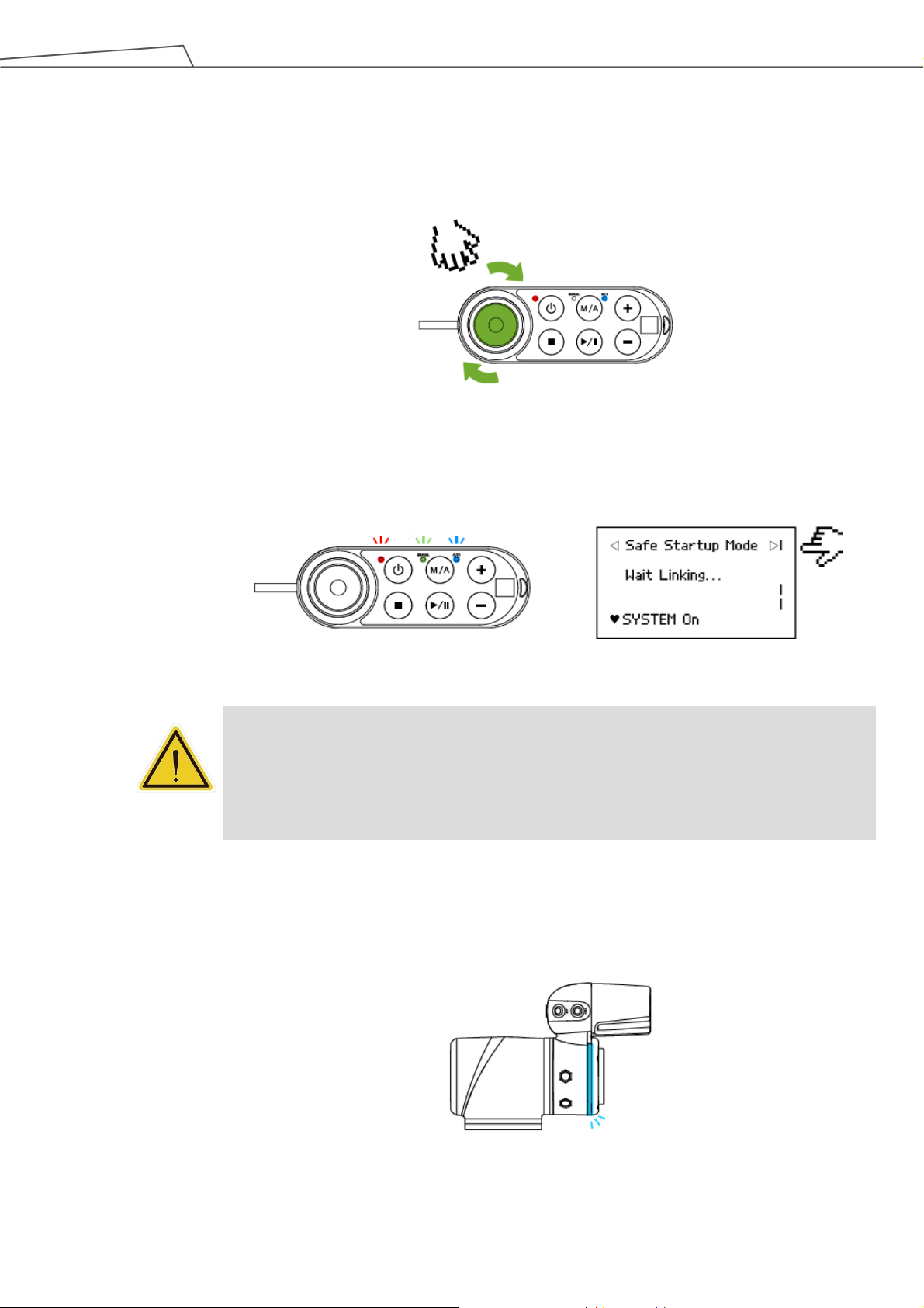
25
instructions shown on the screen to restart the robot.
Step 2. Press the Power Button of the Robot Stick to start the power supply of the Control
Box.
Step 3. Release the Emergency Switch of the Robot Stick by twisting it a quarter-turn
clockwise when the light on Robot Stick starts blinking.
Figure 1: Release the Emergency Switch
The three lights on the Robot Stick keep flashing. For the buttons, lights, and switch
on the Robot Stick, refer to the Hardware Installation Manual.
Figure 2: The Three Lights on The Robot Stick Flashing
CAUTION:
While booting up, if the Emergency Switch on the Robot Stick is kept pressed, the User
Connected ESTOP Input is kept open, or the User Connected ESTOP Input Port without
Robot ESTOP Output is kept open, the boot process cannot be complete. Follow the
Step 4. The Indication Light Ring of the End Module flashes in red during startup. After
the start up is completed, the Indication Light Ring of the End Module flashes in
light blue, representing that it is in the Safe Start Up Mode.
Figure 3: The Indication Light Ring of The End Module Flashing in Light Blue
Software Manual TMflow Software version: 1.82
Page 26
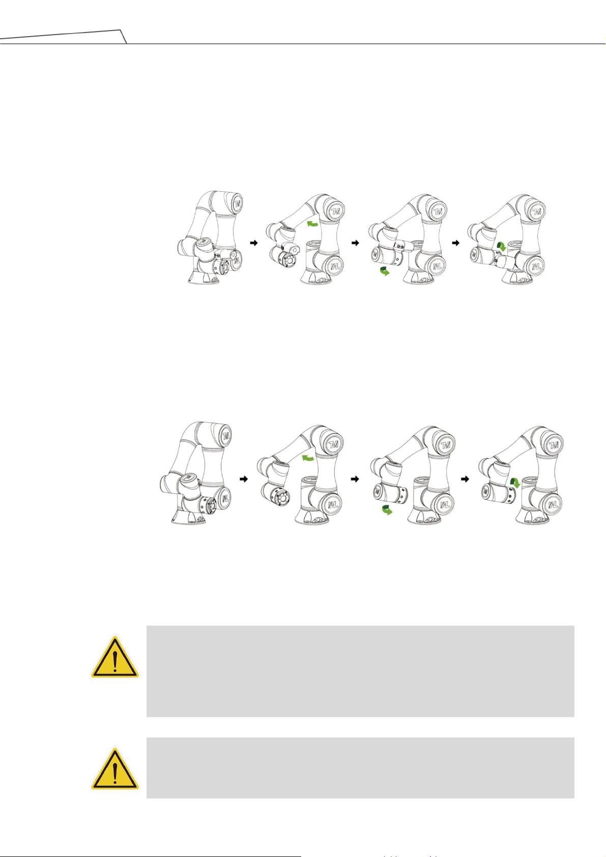
26
release the FREE Button immediately, and the brake of each robot joint will be locked again.
Step 5. Hold the FREE Button on the End Module to release the brakes and manually
move the robot to a relatively safe position. If this is the first time unpacking the
robot, follow the illustrations below to release joints from initial posture.
Figure 4: The Recommended Operating Sequence of Moving the Joints of TM Robot
from Packing Pose to Safe Posture
Figure 5: The Recommended Operating Sequence of Moving the Joints of X series
TM Robot from Packing Pose to Safe Posture
DANGER:
Pay attention when the FREE Button is pressed and the brake is released. The robot's body
will sag due to gravity. When the FREE Button is pressed to unlock the brake, be sure to
support the end of robot and expect some sagging, and hold the end of robot, to prevent
harm such as pinching of the Operator. If there are any problems with the robot sagging,
Software Manual TMflow Software version: 1.82
DANGER:
There is no force compensation in Safe Start Up Mode. This means that it requires more
force to move each joints directly against the motor drive.
Page 27
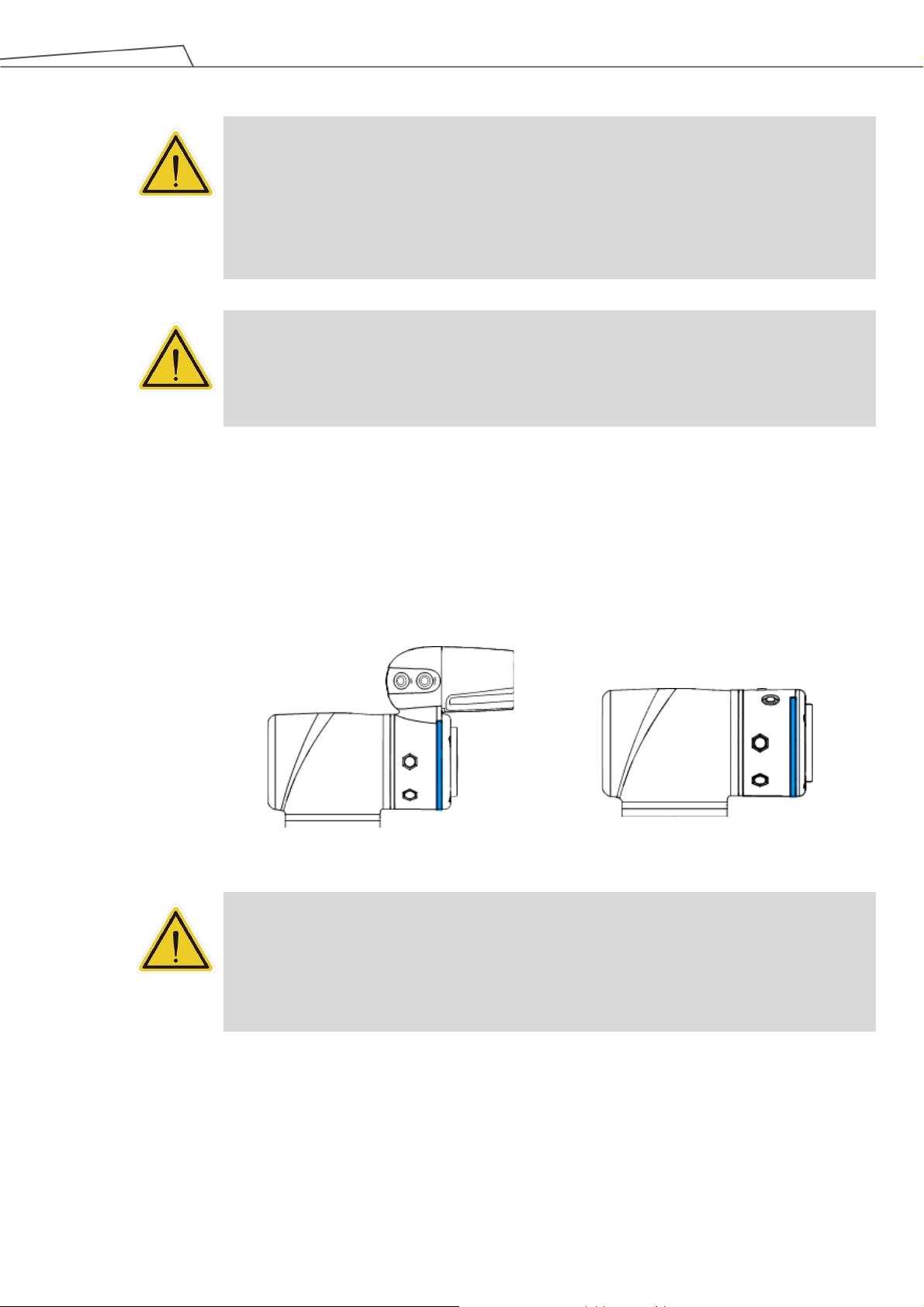
27
and repeat this step to the correct safe posture as shown in the figure.
long distance from the robot flange, will not cause harm during the calibration motion.
the safe posture after unpacking the box are opposite.
CAUTION:
If you do not follow the above instructions to move the robot to the safe posture shown in the
above figure, but continue to operate downwards to release the Emergency Switch, it may
cause certain joints of the robot (especially the fifth joint) to be outside the joint angle limit
when the robot returns to a normal state. At this time, the robot will not be able to start
correctly and the red light will be on. In this condition, press the Emergency Switch again
CAUTION:
During Joint Position Calibration, each joint of the robot will perform a calibration motion.
Make sure the robot pose is in a clear space of at least 5 degrees per joint to perform the
calibration motion before calibration. At the same time, make sure the TCP, which may be a
Step 6. Press and hold the Stop Button on the Robot Stick for about three seconds, and
the robot will enter the calibration process. During calibration, joints of the robot may
move slightly. After the calibration is completed, the Indication Light Ring of the
End Module will return to blue light, indicating that the robot has entered the Auto
Mode successfully and it can be used normally.
Figure 6: The Indication Light Ring of The End Module Returns to Blue Light
CAUTION:
When the startup from the Packing Pose is complete, use the TMflow controller page to
move the robot posture to the origin first (each joint angle: 0, 0, 0, 0, 0, 0), and then use the
FreeBot teaching to move the robot to the Normal Pose (each joint angle: 0, 0, 90, 0, 90, 0)
as shown in the figure below. Note that the joint 2 pointing directions of the Normal Pose and
Software Manual TMflow Software version: 1.82
Page 28
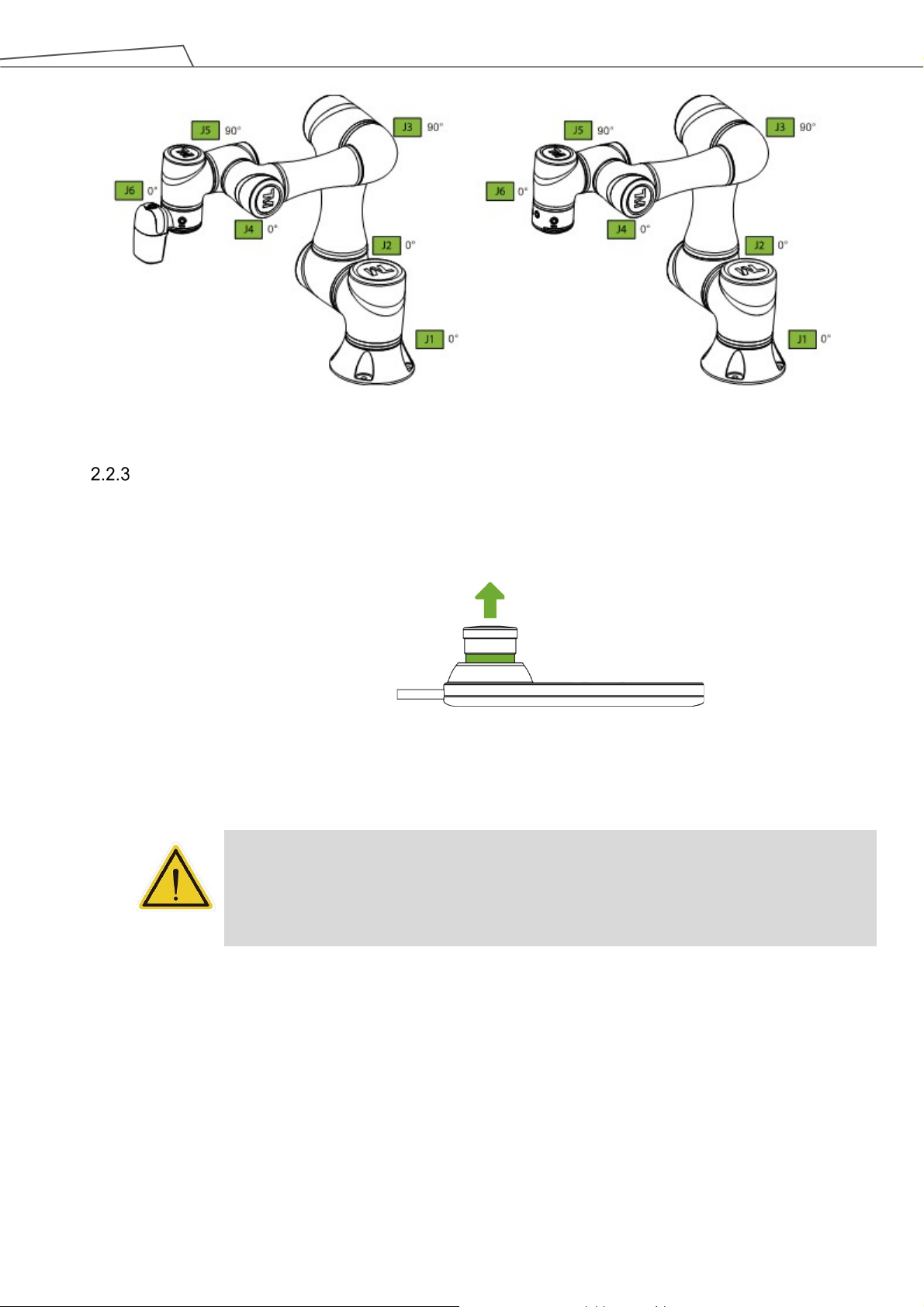
28
instructions shown on the screen to restart the robot.
Figure 7: The Normal Poses
Standard Start Up
Step 1.
Check that the robot's posture is safe.
Step 2. Check that the Emergency Switch of Robot Stick is released.
Figure 8: Release the Emergency Switch of Robot Stick
Step 3. Press the Power Button on the Robot Stick to start the robot.
CAUTION:
While booting up, if the Emergency Switch on the Robot Stick is kept pressed, the User
Connected ESTOP Input is kept open, or the User Connected ESTOP Input Port without
Robot ESTOP Output is kept open, the boot process cannot be complete. Follow the
Step 4. Check the screen on the Control Box. It should now indicate that the system
entered startup mode. The power light on the Robot Stick will keep flashing, too.
Software Manual TMflow Software version: 1.82
Page 29
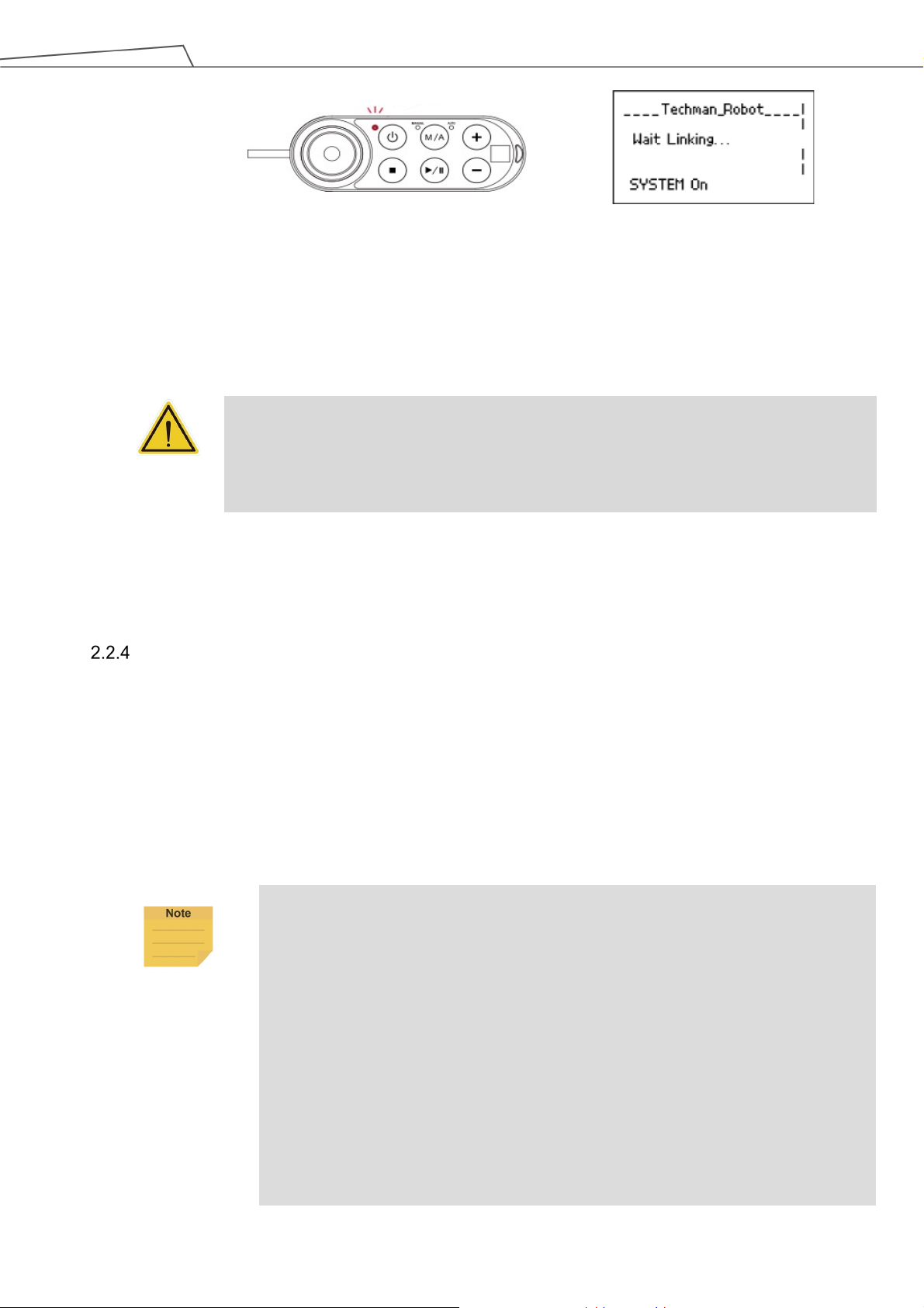
29
a long distance to the robot flange, will not cause harm during the calibration motion.
Minimum requirements of the client device to install TMflow are as follows:
Additional
1. 2010Redistributable_bcredist (x64/x86)
Figure 9: The Power Light on The Robot Stick Flashing
Step 5. When the controller is starting up, the Indication Light Ring of the End Module
displays flashing red light. During the process, the robot will run automatic
calibration, and each joint of the robot will move slightly to calibrate.
CAUTION:
During Joint Position Calibration period, each point of the robot will perform a calibration
motion. Make sure the robot pose is in a clear space of at least 5 degrees per joint to perform
the calibration motion before calibration. At the same time, make sure the TCP, which may be
Step 6. After the controller start up is done, the Indication Light Ring of the End Module
will constantly display blue light. The robot can be used normally at this time.
TM Robot HMI TMflow Operation
TMflow and the TM Robot can be connected in ways as below:
Connect with the monitor, keyboard and mouse to the Control Box. This enables to start
TMflow.
Download the TMflow Client from customer area of the official website, and then install it on
a Windows-based computer (e.g. Windows Laptop/ Windows Tablet). Connect to the robot in
a wired or a wireless network.
NOTE:
Operating System:
CPU:
RAM:
Hard Drive Space:
Display Resolution:
Peripherals:
Supported Languages:
Windows 7 SP 1
Intel i5 series compatibles or above
4 GB at least
2 GB of available space
1366 by 768
USB ports and Ethernet ports
English, Traditional Chinese, Simplified Chinese,
Japanese, German, Korean, Vietnamese, Spanish, French,
Italian, Danish, Dutch, Czech, Hungarian, Romanian,
Portuguese, Turkish, Polish, Thai
Software Manual TMflow Software version: 1.82
Page 30
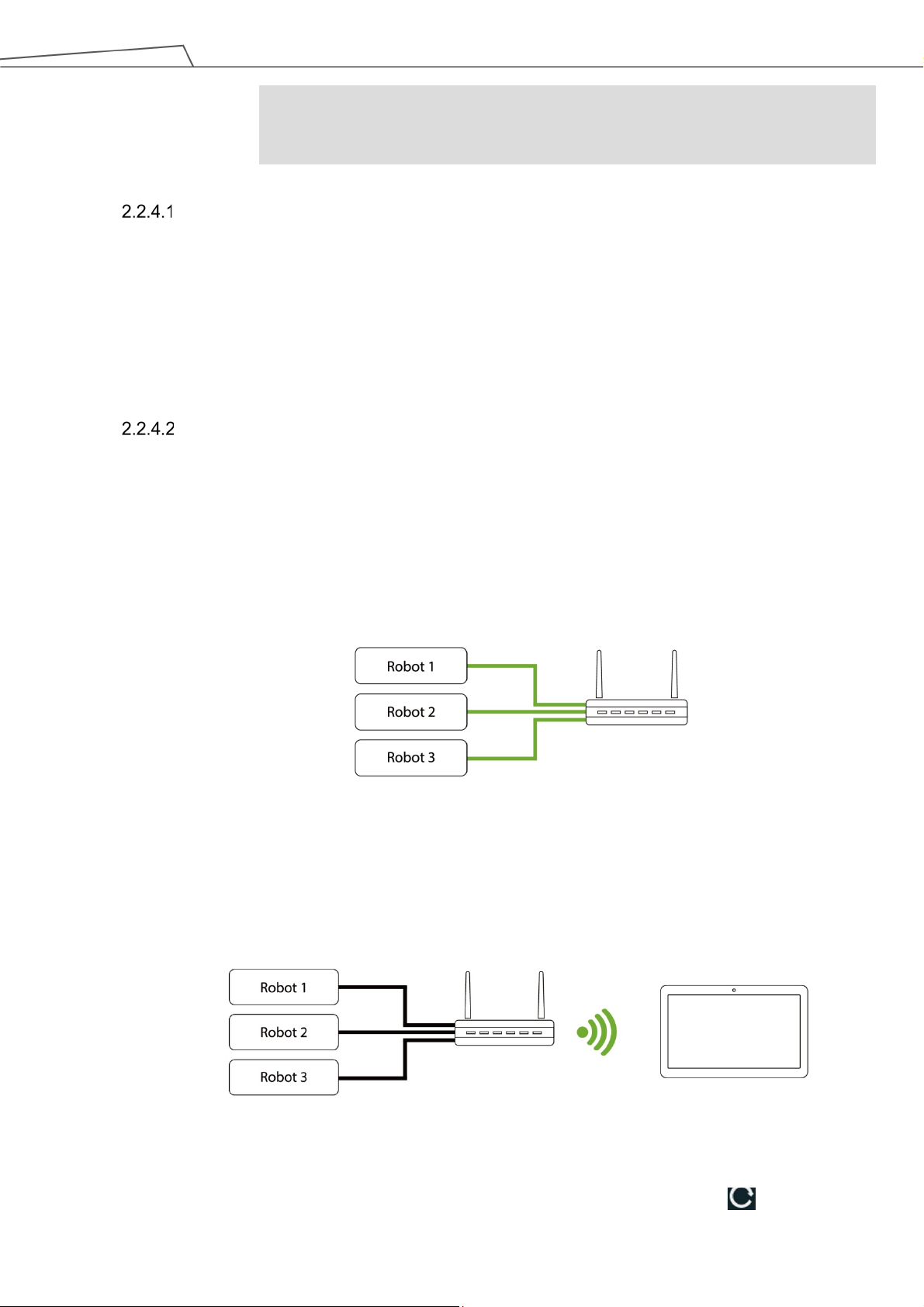
30
4. .Net Framework 4.52 or above.
≡
Requirements: 2. 2013Redistributable_bcredist (x64/x86)
3. 2015Redistributable_bcredist (x64/x86)
Local Operation Method
Step 1. Connect the screen, mouse, and keyboard, to the Control Box.
Step 2.
Navigate to
and click Login.
Administrator by default is not set with password. Click OK to login directly.
Step 3. Click Get Control to get control of the robot.
Wireless Access Point Connection Method
Step 1.
Step 2.
Install TMflow on client device.
Connect the robot to the same physical AP or entity AP of the same network
segment.
Physical AP
Figure 10: Wireless Access Point Connection Method (1/2)
Step 3.
Connect the client network to the above local area network.
Physical AP
Figure 11: Wireless Access Point Connection Method (2/2)
Step 4.
Open TMflow on the client device, click the upper left corner to refresh
Software Manual TMflow Software version: 1.82
Page 31

31
connection screen.
the QR code on the Robot Stick).
Step 1.
Install TMflow on the client device.
the robot Control Box and Client.
Step 3.
Connect the client network to the above local area network.
screen.
connected by the robot's Robot ID.
in the screen and the icon of robot appears on the upper right corner.
Step 7.
Click Get Control to control the robot.
the robot list, and wait for the corresponding Robot name to appear on the
Step 5.
Click the robot icon twice to connect with the robot. Ensure that all the robots
in this network segment appear in the screen. Users can distinguish which
robot to be connected by the robot's Robot ID (the number displayed below
Step 6.
When the robot connection is successful, the icon will appear in the
screen on the robot and the robot icon will appear in the upper right corner.
Step 7. Click Get Control to control the robot.
CAUTION:
Do not mistakenly insert the network cable into the dedicated EtherCAT port of the
Control Box. This action will trigger a robot error.
NOTE:
The connected device will display a green icon, and any other device will display a red
icon.
Wired Network Connection Method
Step 2. Connect the robot and client device to the same physical AP or the physical AP
on the same network segment, or connect the two ends of the network wires to
Step 4. Open TMflow on the client device, click the upper left corner to refresh the
robot list, and wait for the corresponding Robot ID to appear on the connection
Step 5. Click the robot icon twice to connect with the robot. Ensure that all robots in this
network segment appear in the screen. Users can distinguish which robot to be
Step 6. When the robot connection is successful, the icon will appear on the robot
Software Manual TMflow Software version: 1.82
Page 32

32
Physical AP
Figure 12: Wired Network Connection Method (1/2)
Figure 13: Wired Network Connection Method (2/2)
Software Manual TMflow Software version: 1.82
Page 33

33
3. Safety Settings
Overview
This chapter will introduce the safety settings interface of the TM Robot, including the Safety Permission
Settings and Safety Setting.
NOTE:
Upgrading the software with previous versions of hardware will not upgrade the version of the
safety system.
Safety Permission Settings
Users and administrators of TM Robot must set appropriate account password permissions before
starting to use the TM Robot, with appropriate arrangements for access to operator permission for
safety configuration.
When users have completed the startup and activation according to the previous chapter, and entered
the TMflow interface with the default account password to get the control of robot, navigated to
≡ and
clicked Setting to enter the setting page, an option labelled Safety will appear on this page. This is the
safety setting operation area of the product as well as all important settings for the robot. If settings are
altered arbitrarily, it will cause danger during operation. For proper permission settings, refer to
5.8.3
Group and 5.8.4 User Account to create accounts for authorization to access the safety related setting
permissions and grant permission to access Setting, and set all other account and group privileges to
access Setting to change the safety permission settings.
Safety Setting
On the Safety Setting page, there are functions including Performance Safety Settings, Human –
Machine Safety Settings, Safety IO Settings, Cartesian Limit A, Cartesian Limit B, and Project
Speed Adjustment Setting. These function returns a Safety Checksum at the left of the item separator
line at top right to verify the system integrity. Changes in these functions renew the Safety Checksum if
saved. There is also a timestamp of the last modified date and time at the bottom left of the screen. The
timestamp is updated and expressed according to ISO 8601 every time users click the Save button for
new parameters.
Software Manual TMflow Software version: 1.82
Page 34

34
strength to pull to keep from triggering the protective stop.
Cartesian Limit is not available.
NOTE:
In TMflow Software version 1.74 and earlier versions:
Performance Safety Settings is named Safety Stop Criteria.
Human – Machine Safety Settings is named Collaborative Mode Setting.
Safety IO Settings is named Safeguard Port Setting.
Performance Safety Settings
On this page, users can set the TCP speed of the robot, the force of the TCP, the Hand Guide
TCP Speed Limit as an individual speed limit categorized as a cat.2 stop, as well as the speed,
the torque, and the position of each joint. For the related physical meanings and the definition of
the safety functions and the precautions that they represent, read and follow the instructions in
the Safety Manual before the operation or setting can be performed. Users can refer to
C. for values applicable to each model.
NOTE:
When using with Hand Guide, if the pull speed by hand reaches to the Hand Guide TCP
Speed Limit, users will feel the resistance feedback. Under such circumstances, lower the
Figure 14: Safety Setting
Appendix
The default value of the stop criteria is designed to provide a relatively safer working capability of
the robot. A higher upper limit can be set by users. If users want to reach 100% project speed
without triggering these stop criteria, set the limit to the upper limit for each input slot. Since the
capability of the robot is still related to the pose, motion, TCP length, and payload, without these
stop criteria, the robot is still protected by the maximum allowable torque of each joint and stops.
In addition, regarding the life of the robot, refer to the Hardware Installation Manual of the
Software Manual TMflow Software version: 1.82
Page 35

35
of safe space settings or by running incorrect projects.
respective model for the value of rated torque and the limit for repeated peak torque of each joint.
CAUTION:
Angle Setting:
For example, when the first joint position is set to 270° and -270°, then the angle range in
270°~ 271° and -270°~ -271° will become reducing range shown as the blue area in the
figure. When joint 1 moves into this range, the basic moving speed of the robot will be
switched to 250mm/sec for line motion and 5% for PTP motion, to form an angle buffer
region to prevent possible overshoot to the joint limit. At the same time, the angle range in
271°~ 274° and -271°~ -274° is the 2nd buffer range for joint limit as the red area in the
figure. When the joint angle arrives this area robot will stop moving. Users can only operate
the robot by pressing FREE Button to make the robot leave this area.
Figure 15: Angle Setting
CAUTION:
For different TM Robot models the maximum angle limits of each joint may be different. Refer
to the product specifications according to the product model and hardware version.
Human – Machine Safety Settings
When User Connected External Safeguard Input Port for Human – Machine Safety Settings is
triggered, TM Robot will run at a slower speed and a lower joint torque stop criteria by the users'
settings. At this time, a purple light will be added to the Indication Light Ring for users to
distinguish whether the robot is switch into Human – Machine Safety Settings. Users can refer to
Appendix C.
for values applicable to each model.
DANGER:
Note that the functions described in this section are only to assist users in setting the
Human – Machine safety parameters and settings more conveniently. Users should still
perform complete risk assessment according to the robot use environment and conditions
before the robot is used. TM Robot clearly specifies the following potential residual risks:
There is a risk that causes the robot to hit a human body at full speed due to improper use
Software Manual TMflow Software version: 1.82
Page 36

36
complete risk assessment and set appropriate force values.
DANGER:
If using the Compliance function in TMflow, speed is not controlled in Human - Machine
Safety Settings. The robot will still run Compliance function according to the force you set.
If you want to use Compliance function with Human - Machine Safety Setting, complete a
The parameters of Human – Machine Safety Settings can be divided into two parts: one is
Body Region Risk Setting and the other is More Limit Setting. The Body Region Risk Setting
page is shown in the figure below.
Figure 16: Human – Machine Safety Settings (1/2)
For Body Region Risk Setting, users can set the human body region that may be in contact with
the robot in collaborative workspace according to the requirements. The calculation result on the
right side of this interface displays the robot's running speed in the collaborative workspace. The
setting value can be saved after being confirmed by users.The calculation result includes the
value of the automatic reduced moving speed, the value of the automatic reduced point-to-point
movement speed, and the minimum possible contact area between the robot's external device
and human body when entering the collaborative workspace. Users must check the confirmation
field in the lower right corner before saving the setting value, to confirm the area where the robot's
external device may be in contact with the human body is larger than or equal to the area
confirmation value.
This feature is designed for users to quickly set up an initial robot application in collaborative
workspace following the biomechanical limits of each body region listed in ISO/TS 15066*. Users
should still perform risk assessment on real application before deployment. Users shall take
Software Manual TMflow Software version: 1.82
Page 37

37
TM700/900
TM12/14
Default
150 ms
300 ms
Available range
150~800 ms
300~800 ms
this function.
head.
spine and hindbrain.
responsibility for human body region which is not listed in this graph, and ensure the robot does
not have any chance to be in contact with any vulnerable body region such as spine and
hindbrain.
*Default parameters are recommended based on tests with tool length of 135mm and weight of 0.43kg.
NOTE:
Users can set the deceleration time manually in the field after When robot enters
the collaborative workspace, the speed setting will be achieved within.
Check Enable G-Sensor to increase the robot’s sensitivity to collision detections.
This function alone is an auxiliary to increase sensitivity on top of the safety function
and not safety rated, and this function works in all mounting poses. Once this
function is enabled, the impact force will decrease, and the reduction of stopping
time can be negligible. While practicing the risk assessment, users should disable
DANGER:
This function is designed to automatically adjust the speed of robot in the collaborative
workspace following the biomechanical limits of each body region listed in ISO/TS 15066.
Users should consider more and take responsibility for human body regions not listed
separately in the graph by themselves. Also, make sure that the robot does not have any
chance to come into contact with any particularly vulnerable body region like spine, neck, or
DANGER:
The user connected external safeguard input for Human - Machine safety settings provide
users a quick and initial robot application in collaborative workspace following the
biomechanical limits of each body region listed in ISO/TS 15066. Though users can further
adjust the TCP speed, TCP force, joint speed and the joint torque of robot, users should still
perform risk assessment on real application before deployment. Also note that users shall
take responsibility for human body region which is not listed in this graph, and ensure the
robot does not have any chance to be in contact with any vulnerable body region such as
For setting more detailed parameters, users can go to More Limit Setting page.
Software Manual TMflow Software version: 1.82
Page 38

38
Figure 17: Human – Machine Safety Settings (2/2)
In the More Limit Setting page of Human – Machine Safety Settings, users can further adjust
the TCP speed, TCP force, joint speed and the joint torque of robot. Note that the modified values
higher than default values will be highlighted with blue borders, the minimum possible contact
area calculation will be removed. In this case, it’s user’s responsibility and liability to perform risk
assessment and validate safety parameters due to the modification. The values can be saved
after confirmed by users.
Safety IO Settings
This page is to set up the function of User Connected External Safeguard for the TM Robot. For
the electrical connection of the User Connected External Safeguard, refer to the relevant
section of the Hardware Installation Manual with the respective hardware version.
Safety IO Settings comes with User Connected External Safeguard Input Port and User
Connected External Safeguard Input Port for Human - Machine Safety Settings. For the
definition of each safeguard, refer to the Safety Manual for the respective software and hardware
version. Note that users should set up this item appropriately according to the risk assessment.
NOTE:
In TMflow Software version 1.74 and earlier versions:
User Connected External Safeguard Input Port is named Safeguard Port A:
Safeguard Pause or Safeguard Port Setting Pause.
User Connected External Safeguard Input Port for Human - Machine Safety
Settings is named Safeguard Port B: Safeguard Collaborative Mode or Safeguard
Port Setting Collaborative Mode.
Enabling Device Setting is not available.
Software Manual TMflow Software version: 1.82
Page 39

39
Figure 18: Safety IO Settings
Resume Setting of User Connected External Safeguard Input Port
Manual Reset (recommended): For Manual Reset, after the robot has been paused
through User Connected External Safeguard Input Port, even if the trigger condition
is removed, users must manually use the Play/Pause Button on the Robot Stick to
release the pause and return to the original project process and project speed.
Auto Reset: For Auto Reset, after the robot has been paused through User
Connected External Safeguard Input Port and once the trigger condition is removed,
the robot will automatically release the pause and return to the original project process
and project speed.
Mute Joint Torque Monitoring and TCP Force Limit when User Connected External
Safeguard Input signal “LOW”: Check this function to deactivate joint torque
monitoring and TCP force limit when User Connected External Safeguard Input signal
“LOW”.
Resume Setting of User Connected External Safeguard Input Port for Human - Machine
Safety Settings
Manual Reset: For Manual Reset, after the robot has been triggered into Human –
Machine Safety Settings, even if the triggered condition is removed, users must
manually use the Play/Pause Button to pause the robot motion and press the
Play/Pause Button again from the Robot Stick to return to the original project process
and project speed.
Auto Reset (by default for HW 3.0 or earlier): For Auto Reset, after the robot has been
triggered into Human – Machine Safety Settings, and once the triggered condition is
Software Manual TMflow Software version: 1.82
Page 40

40
removed, the robot will automatically return to the original project process and project
speed.
Safeguard Port Setting for the Hardware Version prior to 2.00 (inclusive)
The former section refers to the setting of hardware version 3.2. The Safeguard Port of
hardware version 2.00 has the functions of switching to pause and triggering the
Collaborative Mode. For the connection and use, refer to the corresponding hardware
version of the Hardware Installation Manual. Users shall set up this item appropriately
according to the risk assessment.
Pause: The Safeguard Port will trigger pause. The following settings will set up the
Safeguard Port to reset mechanism during the pause.
Manual Reset (recommended): When you choose Manual Reset, after the robot is
paused through Safeguard Port, even if the trigger condition is removed, users can only
operate the Play/Pause Button or the same action from the Robot Stick to release
pause and return to the original project process and project speed.
Auto Reset: When you choose Auto Reset, after the robot paused through Safeguard
Port. Once the trigger condition is removed, the robot will automatically return to the
original project process and project speed.
Collaborative Mode: Safeguard Port will trigger the Collaborative Mode. Once the
trigger condition is removed, the robot will automatically return to the original project
process and project speed.
Enabling Device Setting (HW 3.2 or newer exclusive)
Enabling Device provides the dual channel input ports for users to connect to a three-position
enabling device. Check to box to apply the setting. Note that the status of this safety setting
will not affect the operation in Auto Mode. When this setting is enabled and connected to the
enabling switch, in Manual Mode, all manual control operations are enabled only when users
press the three position enabling device in the middle position. If the Enabling Device is
released or fully pressed, the robot performs a protective stop. When starting a manual trial
run of the project pressing the PLAY button, the Enabling Device should be pressed in the
middle position. When Enabling Device is released or fully pressed during the Manual Trial
Run mode, the Project Speed will always automatically return to 5%. Connect this function
only to the three-position enabling device compliant with IEC60204-1. Note that the input of
this function has two input statuses only, so the Enabling Device should not have an enabled
output during the procedure from the fully pressed status to the fully released status.
Software Manual TMflow Software version: 1.82
Page 41

41
Cartesian Limit A & B
For users of HW 3.2 or newer, Cartesian Limit A & B are available as a cube or a cylinder with
Operation Space disabled to set the bounds for the robot movement. Any violation to the safety
plane from TCP and/or elbow limits of position will result in a Cat.2 stop for Cartesian Limit A and
trigger Human-Machine Safety Setting in Cartesina Limit B.
To use Cartesian Limit A or B, follow the steps below.
1. Navigate to
≡ and click Setting > Safety > Cartesian Limit A or B.
2. Check Enable Cartesian Limit & Disable Operation Space and check TCP or elbow for
Limits of position.
3. Select from Cube or Cylinder in Cartesian Setting.
For Cube, proceed to check the desired axes bounds, and, in the next fields, input the
integer values of the desired distance in millimeters. Be sure to make the difference
between the upper bound and the lower bound larger than 120 in millimeters.
For Cylinder, proceed to check the desired axis bounds or R for the radius, and, in the
next fields, input the integer values of the desired distance in millimeters. Be sure to
make the difference between the upper bound and the lower bound larger than 120 in
millimeters.
NOTE:
For robots set with Cartesian Limits, it is not possible to run a project with an Operation
Space.
Project Speed Adjustment Setting
Project Speed Adjustment Setting is available to users to adjust or restrict motion speed during
project executions for safety and security.
To use Project Speed Adjustment Setting, follow the steps below.
1. Navigate to
≡ and click Setting > Safety > Project Speed Adjustment Setting.
2. Check Enable Manual Trial Run Mode Speed Adjustment to set the project running with a
flexible speed or uncheck to fix to 5% speed in Manual Trial Run Mode.
3. Check Enable Auto Mode Speed Adjustment to let users adjust speed in project
executions under Auto Mode. Once checked, it is recommended for users to set the speed
adjustement password immediately. The passward is blank by default. When the password
is set, click the Reset Password button to set the password again.
Software Manual TMflow Software version: 1.82
Page 42

42
speed rather than input the speed adjustement password in View.
4. Click Save to keep the setting or Default to restore the defaults.
As users check either item in Project Speed Adjustment Setting, the speed adjustment icon with a
stop sign turns to a tick sign appearing between the speed indicator and the Safety Checksum
icon, and users can learn from the speed adjustment icon to know if it is available to adjust speed
in the current mode.
NOTE:
Once checked Enable Auto Mode Speed Adjustment, if the robot is in auto remote
mode, users can use external commands such as Modbus Slave to adjust the project
Switch between Modes
Switching between Auto mode and Manual mode is prohibited/rejected by the system under
these conditions:
1. The project is running in Auto Mode.
2. The project is running in Manual High Speed Mode.
3. The robot is in Hand Guide Mode.
4. SF15 Enabling Device is triggered (Enabling Device is continuously held in middle position) in
Manual Mode.
5. A Cat. 0 or Cat. 1 stop is in effect.
To switch from Auto Mode to Manual Mode, first press the Stop Button to stop robot operation if
the project is running. Once the project is stopped, press the Mode Switch Button on the robot
Stick and the operation mode will be switched to Manual Mode.
To switch from Manual Mode to Auto Mode, press and hold the Mode Switch Button for a few
seconds. Once the Mode Indicators on the Robot Stick start blinking, press the +/- buttons on the
Robot Stick in this order: "+ - + + -" to change to Auto mode. Go to the pages of View, Run
Setting, or Connect to press and hold the M/A Mode Button and press the +/- buttons on the
Robot Stick in this order: "+ - + + -" to change to Auto mode. The robot will stay still in Auto mode
until you press the play button on the robot stick.
When the robot performs trial run in Manual Mode again, the project speed will start with the
initial speed at 5%. Refer to 4.4 Build and Run Your First Project for how to set the project speed.
Software Manual TMflow Software version: 1.82
Page 43

43
system.
DANGER:
Prior to selecting automatic operation, any suspended safeguards must be set back to
full functionality.
NOTE:
To lock the robot stick in either Auto mode or Manual mode, press and hold the +
Button and the – Button at the same time until either the blue LED or the green
LED blinks, and then press the +/- Button in the sequence of "-, +, -, -, +". The
robot stick is now locked in the respective mode, and the system beeps when any
button is pressed on the locked robot stick.
To unlock the robot stick in either Auto mode or Manual mode, press and hold the
+ Button and the – Button at the same time until either the blue LED or the green
LED blinks, and then press the +/- Button in the sequence of "-, +, -, -, +". The
robot stick is now unlocked in the respective mode.
Users can press and hold the power button on the robot stick to shut down the
Software Manual TMflow Software version: 1.82
Page 44

44
Manual for details.
4. Start Your First Project
Overview
This chapter will describe how to create and run your first project. Only after users have read all
instructions and have a full understanding of the content of this manual and have correctly set the TM
Robots according to the contents of Chapters 2 and 3, can procedures in this chapter be performed.
IM P O RTAN T:
Before starting the very first project, confirm that the User Connected External Safeguard Input
Port for Human-Machine Safety Settings is OPEN and the robot is in the Human – Machine
Safety Settings state as the Indication Light Ring of the End Module is flashing purple. Refer to
the section of Safety Connection in corresponding hardware version of the Hardware Installation
Initial Setting
When your device is connected to the TM robot for the first time, follow the wizard steps to complete the
following settings:
Step 1.
Step 2.
Step 3.
Step 4.
Step 5.
Follow the steps to set up the robot.
Select the interface language.
Set the system time.
Set the Network settings.
Perform voice settings.
Navigate to
≡, and click Setting > Wizard to reset if required.
M/A Mode and FreeBot
Confirm the Operation Mode of the robot at this time. Check the mode Indicator on the Robot Stick,
and identify whether the lamp position is marked as MANUAL (Manual Mode) or AUTO (Auto Mode).
The mode can also be identified by the Indication Light Ring of the End Module, where green light is
Manual Mode, and the blue light is Auto Mode. If it is still in Auto Mode, press the M/ A Mode Switch
Button on the Robot Stick to switch to the Manual Mode to perform the follow-up operations of this
chapter. When the indicator of the M/A Mode Switch Button is green and the Indication Light Ring of
the End Module is green, it is in Manual Mode.
Software Manual TMflow Software version: 1.82
Page 45

45
which may result in errors on joints in the extreme conditions.
Figure 19: Auto Mode / Manual Mode (1/3)
Auto Mode Manual Mode
Figure 20: Auto Mode / Manual Mode (2/3)
In Manual Mode, press the FREE Button to hand guide the robot. The hand guiding function is limited
to Manual Mode.
Figure 21: Auto Mode / Manual Mode (3/3)
IM P O RTAN T:
Make sure the robot stays still, and no extra force applies to the external force sensor, such as
touching the tool or the external force sensor by hand, before releasing the FreeBot button. If
releasing the FreeBot button while the robot is moving, the robot might vibrate or hop for the brake,
Software Manual TMflow Software version: 1.82
Page 46

46
Do not use reserved words such as var in naming.
NOTE:
For users of HW 3.2 or newer, the robot stick comes with the speed indication LEDs as shown below.
Figure 22: The Robot Stick for HW 3.2 or newer
Build and Run Your First Project
If this is the first time you are unpacking the TM Robot, there will be no project in the robot. You can build
your first project according to the instructions of this section. The following project target is to run back
and forth between two points (P1 and P2). The setting method is as follows:
DANGER:
Only after users have read all instructions first and have a full understanding of the content of this
manual and have correctly set the TM Robot according to the contents of Chapters 2 and 3, can
procedures in of this chapter be performed.
Step 1. Confirm the Operation Mode of the robot. If it is not in Manual Mode, press M/A Mode
Button to switch to Manual Mode.
Step 2. Navigate to ≡, and click Project to enter the Project Editing Page.
Step 3.
Choose to create a new project and enter the project name.
IM P O RTAN T:
The project naming supports Latin alphabet in upper case and lower case (A-Z, a-z), numbers
(0-9), and the character “_”.
Step 4.
Enter the project name. The maximum number of characters for naming a project is 100.
Step 5. Press the FREE Button to move the robot to any point by hand guiding and press the
POINT Button to let the project flow generate the point. You can see that the robot
automatically names this point as P1 and has been automatically added after the Start
Node and automatically highlighted.
Software Manual TMflow Software version: 1.82
Page 47

47
Figure 23: Build and Run Your First Project (1/5)
Step 6. Press the FREE Button and move the robot to any other point by hand guiding. Press the
POINT Button to record this point and generate P2.
Step 7. Drag a Goto Node from the nodes menu onto the project flow.
Step 8. Click the pencil icon and click on Set Goto Target. Choose P1.
Step 9.
Press the save icon to complete the project editing.
Step 10. Press the Play/Pause Button on the Robot Stick in the Project Editing Page to start
running the project. At this time, the Indication Light Ring will flash in green. Each time
you start running a project in Manual Mode, the Robot Stick looks as shown.
Figure 24: Build and Run Your First Project (2/5)
Step 11.
In the trial run, the process speed of the project will start at initial speed of 5% as shown on
the top right of the Project Editing Page.
Step 12. Press the + button (increase running speed) / - button (decrease running speed) on the
Robot Stick, to increase or decrease the project speed of the robot. Adjust the speed of
Software Manual TMflow Software version: 1.82
Page 48

48
the robot at this time for an appropriate speed. (You can read the set project speed from
the % number displayed at the top right of the operation interface.)
Figure 25: Build and Run Your First Project (3/5)
Step 13. After setting your preferred project speed, press and hold the M/A Mode Button to store
the project speed. If ended and stopped without any error, the project will be labeled
Tested.
Step 14. Press the Stop Button on the Robot Stick, and go to the Run Setting page to check
your current project file labeled Tested. You can also go to the pages of View, Run
Setting, or Connect to press and hold the M/A Mode Button and press the +/- buttons
on the Robot Stick in this order: "+ - + + -" to change to Auto mode. The robot will stay
still in Auto Mode until you press the play button on the robot stick. Remember that if you
perform a trial run in Manual Mode again, the project speed will start with the initial
speed at 5%. You must perform the previous steps again to set the project speed.
Step 15. Press the Play/Pause Button in Auto Mode.
The speed remains at the project running speed you set, and the speed cannot be
changed in Auto Mode.
Software Manual TMflow Software version: 1.82
Page 49

49
≡
Figure 26: Build and Run Your First Project (4/5)
Step 16.
Congratulations on your successful completion of project editing and running. Press the
Stop Button on the Robot Stick to stop running the project.
Figure 27: Build and Run Your First Project (5/5)
Step 17. Switch over to Manual Mode.
After stopped the project, you can press the M/A button on the Robot Stick to switch over
to Manual Mode.
WARNING:
Running the self-constructing project before completing adequate training may lead to body
collision or human injuries due to the unforeseen robot actions.
Shutdown
There are two shutdown methods:
Method 1:
In TMflow, navigate to
, click Shutdown, and choose Shutdown. When the warning
message appears, click OK to shut the system down properly.
Method 2: Press and hold the power button of the Robot Stick, and release the button when you
hear a beep sound. The power indicator of the Robot Stick is flashing in red and the
robot performs shutdown.
Software Manual TMflow Software version: 1.82
Page 50

50
3. Loosening the power of robot body directly
Figure 28: Shutdown
DANGER:
The following Shutdown methods are prohibited:
1. Unplugging the power plug directly
2. Loosening the power cord of Control Box directly
Software Manual TMflow Software version: 1.82
Page 51

51
vicinity of the icon or the text in the function menu.
5. Operation Interface
Overview
The chapter will introduce the operation interface of TMflow, including the icons in the function menu:
Login/Logout, Connect, View, Run Setting, Project, Setting, and System.
Navigate to
≡ and click to expand the function menu. The listed icons from top to bottom are:
Login/Logout: login/logout to start/stop using the robot
Connect: list the available robots
View: display page when the project is running
Run Setting: project list and the default project to run
Project: create or edit the project
Setting: the robot setting
System: the system setting
Shutdown: turn off the system
Figure 29: Function Menu
NOTE:
When connected from a client device, there is another icon, Leave.
The selection is available when the mouse cursor moves onto the immediate
Login/Logout
The login window will pop up when clicking Login. Enter your account number and password to start
using the robot.
Software Manual TMflow Software version: 1.82
Page 52

52
CAUTION:
The default account is administrator, and the default password is blank.
Refer to Chapter 2 for details, from start up to complete login: Start up and Activation.
Connection
Local Connection
To control the robot with the screen, keyboard and mouse via the Control Box, follow the
instructions below to log in and connect. After completing login, click Get Control as shown
below to control the robot. To release the control to the robot, click Release Control. Refer to
Chapter 2 for the details.
Remote Connection
To control the robot from a remote device (desktop, laptop, or tablet), follow the instructions below
before login. Click the upper left corner to refresh the robot list. Available robots will be
displayed with their images, models, IDs, Nicknames, IP addresses, and occupancy in the list.
Double-click the available robot to bring up the Login pop-up window and allow for login. Click the
Get Control button below the robot to get control. To release the control, click Release Control
again. Refer to Chapter 2 for details. A warning message will prompt users to use the same
version of TMflow for connection if the versions between the client and the host are different.
Software Manual TMflow Software version: 1.82
Figure 30: Get/Release Control (Local)
Page 53

53
when the robot is in Manual Mode or when users get control permission in Auto Mode.
NOTE:
The addresses of Modbus Slave, EtherNet/IP Adapter, PROFINET IO Device, and
Ethernet Slave for robot stick commands (Play/Pause, +, -, Stop) cannot be written to
View
In the view page, users can monitor project progress and the robot, as the figures below from left to right
are Display Board, IO, Simulator, Status, Force Sensor, and Vision Viewer.
Figure 31: View
IMPORTANT:
The robot provides remote and local multi-logins, but only one person can get control at
a time.
Display Board
In Display Board, users can monitor the project running status such as the vision job result at left
and the status display at right. The status display contains both descriptions and variables that
can be switched by and buttons on the upper right corner. The
description content can be changed through the Display node, and the variable can be changed
through the Display Management in the project.
Software Manual TMflow Software version: 1.82
Page 54

54
Figure 32: Display(1/3)
Once the robot is in auto mode, users can see the page for speed adjustment password input
after clicking the variable button. If checked Enable Auto Mode Speed Adjustment in Project
Speed Adjustment Setting of the robot, users can adjust the project speed at the local site after
entering the speed adjustment password.
Figure 33: Display(2/3)
Software Manual TMflow Software version: 1.82
Page 55

55
log fold up automatically.
Figure 34: Display(3/3)
NOTE:
When an error occurred:
In Manual mode
In Auto mode
1. The system will return to the Project Editing Page, highlight the node
induced the error, and expand the system log with the error code.
2. If there is no account currently logged in or the logged in account does
not come with the privilege to open the project, the system will not
return to the Project Editing Page but expand the system log with the
error code.
3. The contents in the Display Board does not go away even if users go
back the Project Editing Page until the project runs again.
4. The system log does not fold up automatically.
1. The system log expanded at right and the once grayed out Flow
button turned on on the top left.
2. Users can click Flow to generate the project flow with the node
induced the error highlighted. If the flow did not induce the error, the
highlight is on the last executed node.
3. The system displays the page induced the error only and highlights the
node induced the error.
4. Users can switch to Manual mode to correct the node induced the
error with the function menu or press the play button of the robot stick
without correcting to make the Flow button gray out and the system
Flow
In Manual Mode, the flow will be displayed with the focus on the current processing node while
the project is running. Switch off the Auto Focus-Tracking icon at top right to scale the flow with
the + and the – button at bottom right. Through this page, users can conveniently monitor the
Software Manual TMflow Software version: 1.82
Page 56

56
simultaneously to function as the middle button.
process as well as properly optimize and modify the process. In Auto Mode, this page will not
display.
IO
IO provides IO status monitoring and operation tools for users to monitor the status of the
digital/analog input and to operate the digital/analog outputs in this page. When the project is
running, the IO is controlled by the project and cannot be changed manually.
Figure 35: IO
Simulator
In Simulator, users can monitor the current robot posture. Press and hold Ctrl on the keyboard
and, with the right button of the mouse depressed, rotate the 3D model by dragging the mouse.
Press and hold Ctrl and, with the left button of the mouse depressed, zoom in and out of the 3D
model by dragging the mouse up or down. Press and hold Ctrl and, with the middle button
depressed, move the 3D model by dragging the mouse. Press the icon on the screen to
scale the sight of view to a proper size. The information of the Joint Angle and TCP Coordinate
status of Robot base is at the right.
NOTE:
If your mouse comes with a scroll wheel, it is the middle button. If your mouse does not
come with a scroll wheel or a middle button, you can press the left and the right buttons
Software Manual TMflow Software version: 1.82
Page 57

57
Figure 36: Simulator
Status
In Status, Controller Temperature, Robot Voltage, Robot Power Consumption, Robot
Current, Control Box I/O Current, and Tool Side I/O Current can be monitored. The currently
running project or preset project will be displayed on the upper right corner.
Vision Viewer
In Vision Viewer, users can check results, images, and variables ended up with the vision job.
While the project is running, this page stays at which the current vision job finished and keeps
updating, and users can pause the project and check with the finished vision job in the meanwhile.
When the project is stopped, information of the vision job and images remain in Vision Viewer
Software Manual TMflow Software version: 1.82
Figure 37: Status
Page 58

58
Use the slider for the outputs beyond the available viewing area.
until the next project execution. Vision Viewer is available in Manual Mode, Auto Mode, and
TMflow client.
The resolution in the Vision Viewer Live Video is 640*480. If the system comes with the external
SSD, users can use the magnifier to enlarge the selected region on the Live Video for 1, 2, or 4
times.The magnifer is not available if no external SSD is presented or not checked Save Source
Image in Save Job > Save Image Setting of the vision job.
NOTE:
If the variable outputs more than the available length in Vision Viewer, users can
move the cursor on the variable and the system will prompt its entire content.
IMPORTANT:
The TM SSD is a requisite for using Vision Viewer with TM 3DVision to check images.
Figure 38: Vision Viewer
The finished vision jobs will append to the right as thumbnails in the list below Live Video. When
the project is paused or stopped, click on the thumbnail will highlight the thumbnail and the job
name and the camera type will show above the list. Double-click on the thumbnail to view the
respective vision job. Use the left arrow on the list to go back.
Run Setting
In Run Setting, all executable projects can be viewed. For instance, displayed on the file
represents this project is running currently, displayed represents this project can be run in Auto
Software Manual TMflow Software version: 1.82
Page 59

59
The number suggested as the TCP speed renews approximately every 1 second.
Mode. If the project is to be run in Auto Mode, it must go through the Trial Run process. The running
method of Trial Run is performed in Manual Mode. After adjusting the speed, while the project is
running, press and hold the M/ A Mode Button and press the +/- buttons on the Robot Stick in this
order: "+ - + + -" to change to Auto Mode and complete the project with complete Trial Run procedure
and ensure the safety while running. The robot will stay still in Auto mode until you press the play button
on the robot stick. Remember that if you perform trial run in Manual Mode again, the project speed will
start with the initial speed at 5%.
Figure 39: Single Project Icon
Project
Navigate to ≡ and click Project to start creating and editing the flow. As shown in the figure below, the
top is the Project Editing Toolbar, and the left is the node menu, the right sidebar contains system log
and system function menu. Move the mouse cursor on the icon to read its function on the ribbon. show
At the top right, icons at the right of the item separator line can be clicked for more information by
clicking to expand the system log folded at the right and to check the TMflow version. Icons at
the left of the item separator line are for indications only such as suggests your device occupied the
robot, , no one occupied the robot, and , someone occupied the robot. The number comes with
㎜/s suggests the TCP speed, and the percentage suggests the project speed. For HW 3.2 users, the
robot stick comes with the color LED speed meter, and the speed meter syncs with the project speed of
TMf low.
NOTE:
There would be some buffer/deviation between the number suggested as the TCP
speed and the value calculated from safety monitoring function. The suggested
number as the TCP speed is for reference only.
While editing the project, users can click to expand the system function menu folded at the right,
and click to redo or click to undo changes of adding normal nodes, duplicating normal nodes,
or deleting normal nodes up to 5 steps.
Software Manual TMflow Software version: 1.82
Page 60

60
due to the operations of the Component, the Subflow, and the Thread.
Hot Key
Function
Hot Key
Function
Hot Key
Function
Hot Key
Function
Manager
project
Manager
project
NOTE:
The 5 steps of redo or undo changes do not apply to adding, duplicating, and deleting of
the Component, the Subflow, and the Thread as well as normal nodes that disappear
Ctrl shift P Play/Pause Esc X, escape Ctrl Z Undo F1 Step run
Ctrl shift M M/A Enter OK Ctrl Y Redo F2 Diagnosis
Ctrl shift [ - Ctrl N New project Ctrl C Copy F3
Point
Ctrl shift ] + Ctrl S
Ctrl shift 9 Info Ctrl O
Ctrl shift E Error Log F6 Variables
Save
Open
Ctrl V Paste F4
Delete Delete F5 Controller
Base
Table 4: Keyboard Hot Keys in TMflow
Figure 40: Project Editing Page
Project Editing Toolbar
The project editing toolbar is located at the top of the Project Editing Page. From left to right the
functions are Create New Project, Save Project, Open Project, Step Run, Diagnosis, Point
Manager, Base Manager, Controller, Variables, EditBlock, Current Base and Base List,
Current Tool and Tool List, and Display Manager.
Create New Project
Click to create a new project. The project naming supports Latin alphabet letters in upper
case and lower case (A-Z, a-z), digits (0-9), and the character ‘_’. The maximum number of
Software Manual TMflow Software version: 1.82
Page 61

61
Tracking User Manual for details.
characters can be used in naming a project is 100.
NOTE:
Check Component Editor to create components. Refer to 16 TM Component Editor for
details.
Check Conveyor Tracking to create projects for conveyor tracking. Refer to TM Conveyor
IMPORTANT:
When saving the file, if there is a file with the same filename, it will be overwritten. Save the
file with care to avoid file loss.
Save Project
Click to save the project. The project naming supports Latin alphabet letters in upper
case and lower case (A-Z, a-z), digits (0-9), and the character ‘_’. The project is saved with
the date and the time of build and last updated. If the previous project is not closed properly, a
message will prompt when the project is opened. If select Yes, the last saved file version will
be opened and all subsequent modifications will be discarded. If select No, the file will open
with the last state before closing, and for users to perform the file saving operation.
NOTE:
A warning message will prompt users to save the current project if unsaved. Click Yes to save and
close the project, No to simply close the project, or Cancel to ignore the message.
Open Project
Click to open existing projects. Projects are listed with the build date and the modified
date. Users can sort projects in the list with the buttons of reverse alphabetical, alphabetical,
or chronological. Click the Batch Delete button to select multiple projects to delete. Click on
the name of the project to select the project to delete. Repeat the step if there are more
projects to delete or check the box next to Select all to select all projects, and click Delete
button to delete the projects. Click the left arrow icon on the top left to exit.
Software Manual TMflow Software version: 1.82
Page 62

62
Figure 41: Open and Delete Project View
IMPORTANT:
The currently opened project cannot be deleted and deleted projects cannot be
restored.
Step Run
Step Run is used to confirm accuracy of the edited motion. The first node of a Step Run can
be a Start, a Point Node, or any node that is not grayed out. This allows users to easily
evaluate the correctness of the node/motion. Step Run can start running from the selected
node to have the robot moving by pressing and holding on the screen or the + button on
the Robot Stick. At any time, releasing on the screen or the + button on the Robot
Stick will stop the robot movement, and pressing and holding on the screen or the +
button on the Robot Stick again will start the robot moving from where it stopped. When the
Step Run pane displays (Node name)_finish, the node running is completed. Release
on the screen or the + button on the Robot Stick and press and hold again to continue to the
next node. If the Step Run window is open, the FREE button at the End Module cannot be
used to hand guide the robot. Also, both the variable system and the decision formula will not
operate. When there is a logical branch node (e.g., If Node, Gateway Node) the path of pass
or fail can be selected freely to check that each decision branch’s internal motion
programming is correct using Step Run.
Software Manual TMflow Software version: 1.82
Page 63

63
the Pallet node will only run for the first point.
Figure 42: Step Run
IMPORTANT:
When using Step Run through a Subflow node, click RUN to enter the Subflow
page, or click another node to skip the Subflow steps. Although the variable system
will not operate, the Vision node will run. The Vision node parameter value and
output value can be refreshed through a Step Run Vision node to facilitate
subsequent programming and fine tuning. Since the variable system will not work,
Point Manager
Point Manager lists all points and their parameters including the category of points: General
point, fine-tuning point, dynamic point, the reference Base to which the point is attached,
and the tools used by the point. For the creation and applicable nodes of all categories of
points, refer to the Point node, F-Point node, and Touch Stop node. In the Point Manager,
represents Vision Base, and represents Custom Base. Click the pencil icon at the
left side of the point to go to the information page of the point where users can modify the
point name and find out the reference coordinates, tools, and detail coordinates of the point:
[X, Y, Z, Rx, Ry, Rz]. Users can set the type of motion with either PTP or Line and its speed at
the bottom.
Software Manual TMflow Software version: 1.82
Page 64

64
Figure 43: Point Manager (1/2)
Users can use the dropdown to filter available points in the list and sort the list with the
buttons of the point list, reverse alphabetical, alphabetical, or chronological. Click Batch
Delete to select multiple points to delete. The exclamation mark denotes unused in the flow.
For example, if Point["P1"].Value functions in the flow, no exclamation mark will present since
it regards P1 as used in the flow. However, if written as Point[var_A].Value and var_A = "P1",
it may regard P1 as not used in the flow.
Controller: Enable the Controller to operate robot.
Overwrite new pose to this point: Write the current robot position and posture at this
point and overwrite the original value.
Software Manual TMflow Software version: 1.82
Figure 44: Point Manager (2/2)
Page 65

65
unintended motion.
Re-record on Another Base: Re-record this point on another Base, change the
reference coordinate.
Re-record on Another TCP: Re-record another tool for the point when users want to
run the same position with a different tool. After selecting TCP, users can select Keep
Pose to hold the flange position and transfer the TCP position or Keep Path to transfer
the flange position and hold the point position. Click OK when done.
Save as: Save as other point with new name.
Delete This Point: Delete the selected point.
IM P O RTAN T:
The point system and the nodes are mutually independent. The changes made in
the Point Manager will be applied to all the nodes that use this point. Before the
change, check all the nodes sharing this point again to avoid the occurrence of
Base Manager
Base Manager will list all the Bases that can be used, the tag will indicate the Base
used by the robot at that time, represents Vision Base, and represents Custom
Base. Click the pencil icon at the left side of the specific Base to access the information page
of the Base. Clicking Set as the current base will change the current reference coordinate
used by the robot to this Base. Beneath that information, there are tools provided for users to
operate the Base. Refer to Chapter 6 Point and Base for the definition of Base and 7.2
Create a Custom Base for the details on how to create a Custom Base.
Users can use dropdown to filter available base in the list, and sort the list with the buttons of
base list, reverse alphabetical, alphabetical, or chronological. Click the Batch Delete button
to select multiple bases to delete. The exclamation mark denotes unused in the flow. For
example, if Base["base1"].Value functions in the flow, no exclamation mark will present since
it regards base1 as used in the flow. However, if written as Base[var_A].Value and var_A =
"base1", it may regard base1 as not used in the flow.
Software Manual TMflow Software version: 1.82
Page 66

66
Figure 45: Base Manager
Controller
Controller provides users with direct control of the robot from motion control, IO control and
FreeBot settings. Motion control includes three tabs: Joint, Base, and Tool, which
correspond respectively to “move according to the joint angle setting”, “move according to the
robot Base or the current Base”, and “move according to the Tool Coordinate”.
The Robot Link icon above the Joint tab is in green and connected when the I/O states, the
safety connector states and the coordinates values are correct. If in gray, the Robot Link is
disconnected, and the states and the values are not adequate for reference.
Software Manual TMflow Software version: 1.82
Figure 46: Controller
Page 67

67
command with a large gap.
Coordinate.
Motion Control: In the tab of Joint, Base, or Tool tabs, there are two kinds of motion
control methods:
Single-joint/single-axis movement
To use single joint/single-axis movement, click the joint/axis to be moved first, then
press or on the left bottom corner, or press the + or - button on the Robot
Stick to move the joint/axis in a positive or negative direction.
Moving to a specific target
To move a specific target, enter the target in the textbox on the right, then press and
hold the Move button below to move the robot to the target position.
NOTE:
The selections in the dropdowns, the solid circles, and the input values in the fields
will remain even after switching the tabs until users exit the Controller.
Controller comes with the protection mechanism to prevent the joint to report the
hardware error with the oversized interpolations from sending the position
IM P O RTAN T:
The Base tab is used to move to a specified target with respect to the specified Base,
and the Tool tab is used to move in a specified direction with respect to the To ol
IO Control: Click IO tab to open the IO control page. In the IO control, the output value
of each IO can be controlled independently, including Control Box IO, End Module IO,
Camera Module IO, and Safety Connector IO. For detailed IO specifications and
applications, refer to Chapter 12.3 IO.
NOTE:
Safety Connector IO is for HW 3.2 or newer exclusive.
Safety Connector IO is read-only and users cannot change the state in TMflow.
Software Manual TMflow Software version: 1.82
Page 68

68
the indication light ring to green and start over.
conditions.
Figure 47: Controller (IO Control)
FreeBot: In FreeBot, it defaults to Robot Joints as the Control Mode and the
movement limits of the robot while pressing the FREE Button can be set. The settings
are divided into Free all joints, Free XYZ, Free RXYZ, SCARA like and Custom
Setting. When the control mode is Robot Joints, Check Clear Payload and press the
FREE Button to clear payload for obtaining the correct TCP force and joint torque.
Users can set the Control Mode to F/T Sensor for hand guiding in the current project
and select the F/T sensor in the dropdown if installed an F/T sensor to the robot. If users
exit the project, hand guiding with the F/T sensor becomes unavailable until users set
the Control Mode to F/T Sensor in Controller again.
NOTE:
Users cannot hand guide when the project is running.
All safety functions are effective in hand guiding with the F/T sensor.
The indication light ring turns to red if an error occurred after users pressed the
FREE Button to begin hand guiding with the F/T sensor. Press the FREE Button in
the End Module or the Stop Button on Robot Stick to troubleshoot the error to turn
IM P O RTAN T:
Make sure the robot stays still, and no extra force applies to the external force sensor,
such as touching the tool or the external force sensor by hand, before releasing the
FreeBot button. If releasing the FreeBot button while the robot is moving, the robot
might vibrate or hop for the brake, which may result in errors on joints in the extreme
Software Manual TMflow Software version: 1.82
Page 69

69
Button
Function
restricted
Figure 48: Controller (FreeBot Control)
Free all joint
Free all joint: Freely drag the robot while pressing the FREE Button.
Free XYZ: Use the FREE Button to make the robot performing translation-only
motion in Robot Base.
Free RXYZ: Use the FREE Button to make the robot performing rotation-only
motion in Robot Base.
SCARA like: Use the FREE Button to make the robot performing motion on X, Y, Z,
RZ directions of Robot Base as the traditional SCARA robots. This mode is
suitable for teaching simple pick and place jobs to avoid accidentally causing
unnecessary rotation in degrees of freedom when teaching.
Custom Setting: Freely set the degree of freedom to be released and fixed, to
facilitate hand guiding. Once set the selection, it prompts an error message window
if there is no box checked in Base Coordinate or Toor Coordinate.
Six Degrees of Freedom, the robot end movement and posture change are not
Free XYZ Three Degrees of Freedom, the robot end can only move XYZ directions.
Free RXYZ Three Degrees of Freedom, the end can only change its orientation
SCARA Four Degrees of Freedom (X, Y, Z, RZ)
Custom Setting Degrees of Freedom to be set by users.
Table 5: FreeBot Degree of Freedom Limitation
Software Manual TMflow Software version: 1.82
Page 70

70
correct.
Do not use reserved words such as var in naming.
IM P O RTAN T:
The FreeBot setting is still valid after the controller page is closed. Therefore, if users find that the
robot cannot be moved in certain degree of freedom, check whether the FreeBot setting is
Variables
TMflow has its own variable system. All types, names, and initial values of all variables can
be seen in the variable list. The variable types include both single variables and arrays, and
the new variables can be added through the Create Variable button or the Create Array
button. In the naming rule of variables, only the digits, underscore, and letters (both
uppercase and lowercase letters) are supported. Users can sort variables in the list with the
buttons of reverse alphabetical, alphabetical, or chronological.
Users can use Import/Export to read text files as entities, and users can break them down
into pieces or trace them back to the plain code with programming. The text file to read must
be less than 2MB in the assigned path. Users can use Text File Manager in Robot Setting
to check text files in the list. Variables created with the type of string can read data in the text
files as values. Array, Global Variables, and Variables created with other types are not
supported.
IM P O RTAN T:
Use " " to enclose the string when inputting the string value to avoid being
treated as a variable.
EditBlock
By extending the EditBlock menu, multiple nodes can be selected, either by dragging the
mouse, while pressing the left mouse button, to draw a frame around the desired icons, or by
simply clicking each desired icon. Clicking a selected icon deselects it. Users can drag and
drop all the selections, click the Copy and Paste icon to copy and paste all selected nodes,
or perform Base Shift or Speed Adjust for all nodes. Moreover, users can set Payload with
a value or a variable in integer, float, or double, check the options in Blending to reduce the
number of robotic brakes and the cycle time, and Precise Positioning to set how nodes
locate in particular. All EditBlock related behaviors, including copy-and-paste function, can
only be performed under the same project.
Software Manual TMflow Software version: 1.82
Page 71

71
Figure 49: EditBlock
Current Base and Base List
Base list will list all Bases for this project and also indicates the Current Base. In the base
list, the front symbol represents the type of Base, and represents Vision Base,
represents Custom Base. The Base displayed in the box is the Current Base and can be
replaced through clicking the list.
IM P O RTAN T:
When users click on the Base List and add a new point, the point will be recorded on
the Current Base.
Figure 50: Base List
Current TCP and TCP List
TCP list will list all the TCPs. In the TCP list, the front symbol represents the type of tool,
represents the general TCP, and represents the built-in TCP list of the hand-eye
camera. The TCP displayed in the box is the current TCP, and can be replaced by clicking on
the list.
Software Manual TMflow Software version: 1.82
Page 72

72
IM P O RTAN T:
When users click the TCP list and add a new point, the point will be recorded with the current
TCP.
Figure 51: Tool List
Display Manager
In Display Manager, users can set the variables to be displayed on the display panel and
interact with users when the project is running. Variables are divided into two types: displayed
to users and input by users. The page where users may input variable value can be protected
with a password, to avoid unauthorized operators intervening with or modifying the robot's
motion behaviors by modifying the variables. On the top part of the display management
panel, the time period of the refreshing of the display of variables can be selected from 300,
500, or 1000 in milliseconds. The variable will update the display information according to the
set time. Set the refresh time appropriately to avoid users receiving wrong variable
information.
Software Manual TMflow Software version: 1.82
Figure 52: Display Manager
Page 73

73
nodes desired to be connected to connect.
Node Menu and Flow Editing Area
In the Project Editing Page, users can create projects. The node menu in the left side is a list of
nodes that can be used. Drag the icon of each node to the Flow Editing Area to create Flow.
Users can click the pencil icon on the node to name the node in the field next to Node Name if
available. The maximum characters available in the field is 50.
Figure 53: Project Edit (1/3)
The green triangle at the top left of the tab denotes in use currently. At the top right of the project
editing page, users can click , , or to sort the tabs of the project editing pages in the
orders of reverse alphabetical, alphabetical, or chronological, and click as a dropdown to
switch between subflows.
At the bottom right of the project editing page, users can click or to change display
percentage for easier reading, click to enable automatic connection mode by clicking any
two nodes in the automatic connection mode to connect both of the nodes based on the clicking
order, and click again to exit the automatic connection mode upon completion of
programming.
NOTE:
Tabs will be sorted by types with colors in the order of the following.
Thread (pale yellow) > Subflow (pale blue)
Identical user-defined names of threads are sorted chronologically.
If you use a touch screen for project editing, automatic connection mode will
greatly simplify your connection process, dragging between each endpoint is no
longer needed, simply enable the automatic connection mode and click on the
Software Manual TMflow Software version: 1.82
Page 74

74
Users can click at the top right, select nodes, and click the icon of the desired arrangement at
the top right to align nodes in the page as shown below. The first selected node acts as the
alignment node for the other nodes. If the first node is deselected, the second selected node
becomes the alignment node.
Figure 54: Project Edit (2/3)
Figure 55: Project Edit (3/3)
Project Function Menu
The Project Function Menu will display the settings and tools related to the project, including
search function, Operation Space, Modbus Device, Set IO while Project Error, Set IO while
Project Stop, Stop Watch, View, F/T Sensor, Serial Port, Path Generate, Joint Loading, and
Software Manual TMflow Software version: 1.82
Page 75

75
Network Device.
Figure 56: Project Function Menu
Search Function
In Search Function, the search can be performed by the node name or variable name. Click
the first search box to determine the search target (searching with node name or variable
name used in the node). If searching with a node name, select , and input the keyword
in the search box behind it. If searching with a variable, select , and input
the variable in the input box. The in the input box can be clicked to input from the pop up
variable list, or input the keyword directly. The search limit condition can be specified below
the search box, for users to narrow the search range so that users can filter out the desired
targets. If you want to jump to a specific search result, click in front of the item in the result
list directly. Users can enter an asterisk in the node name to search for all similar nodes in the
process. If an exclamation mark is displayed in the search result, it denotes that the node has
not been set, and users must enter the node to complete the required settings.
Software Manual TMflow Software version: 1.82
Page 76

76
Figure 57: Searching Pane
Operation Space
Operation Space can be used to set the operation space configuration of the project. Refer
to Chapter 15 Operation Space for instructions.
Modbus Device
Modbus Device can be used to set the Modbus master/client in the project. Refer to 12.1
Modbus for instructions.
Set IO while Project Error
This tool can set the IO output status when the project has an error. Refer to 12.3 IO for
instructions.
Set IO while Project Stop
This tool can set the IO output status when the project stops. Refer to 12.3 IO for instructions.
Stop Watch
Through Stop Watch, users can calculate the running time elapsed between two nodes, plan
the motion, manage the production cycles more conveniently through the Stop Watch
runtime analysis tool, and optimize time for each flow. After clicking Stop Watch, click New to
add a stop watch. Stop Watch includes four parts, the beginning node, the ending node,
records in a specific variable, and the note description. Check the bullet before Start or End.
Then, click the note to be configured to complete the configuration. To save the variable,
when Stop Watch is running, the time result obtained while running can be output as the
Software Manual TMflow Software version: 1.82
Page 77

77
variable to help users analyze this parameter. Select a double type variable in the variable list
and fill in the variable box to use this function.
Figure 58: Stop Watch Setting Page
View
View provides users with a quick view of the current camera's live image. The camera name
can be selected in the upper left corner of the image. Click below the image to bring up
the camera adjustment parameters.
F/T Sensor
Refer to 14.2 F/T Sensor for instructions.
Software Manual TMflow Software version: 1.82
Figure 59: View Tool Floating Window
Page 78

78
Serial Port
Users can add devices with serial communication interfaces in Serial Port. Simply click the
icon of Serial Port to manage the serial port devices.
Figure 60: Serial Port (1/2)
Figure 61: Serial Port (2/2)
To add a device, click Add, enter values for Device Name, Com port, Baud rate, Data
bit, Stop bit, Parity, Time Out in the respective fields as well as check the flow control
options, and then click OK.
To edit a device, click on the name of the device, and click on the pencil icon to edit.
Every field but Device Name is editable.
Software Manual TMflow Software version: 1.82
Page 79

79
Users can also input a custom baud rate in the dropdown.
motion record as a path file to use in the path node.
conditions.
To delete a device, click on the name of the device, and click .
NOTE:
The Modbus tab in Expression Editor is replaced by the Connection tab, and
Modbus is in the Protocol dropdown.
The Baud rate dropdown offers choices of: 300, 1200, 2400, 4800, 9600, 14400,
19200, 38400, 57600, 115200.
Path Generate
In Path Generate, users can generate complex curves by hand guiding with the F/T sensor.
Simply click the icon of Path Generate to use the function.
Create a new motion record.
Open a motion record or a path file.
Save as a path file applicable to the path node.
Choose the base and the tool in the dropdowns at top right. Click the record icon to start
recording the path. Hand guide the robot moving while recording is in progress. Click the
stop icon to stop recording.
Click the Time button to set Time Sampling parameters. Click the Position button to
set Position Sampling parameters. Points on the path in the 3D viewer vary from Time
Sampling and Position Sampling.
Click the Run button for the trial run with the recorded path. Users can set Direction,
Data Typ e , or Speed. Click the Move (+) button or the + button of the robot stick to move
the robot along the recorded path. Hold the button for continuous moving. Click the
Reset button to set Direction, Data Type, or Speed again.
NOTE:
The motion record is generated after recording the path with the lowest possible sample
rate and the distance log. The motion record is not applicable to the path node. Save the
IM P O RTAN T:
Make sure the robot stays still, and no extra force applies to the external force sensor,
such as touching the tool or the external force sensor by hand, before releasing the
FreeBot button. If releasing the FreeBot button while the robot is moving, the robot
might vibrate or hop for the brake, which may result in errors on joints in the extreme
Software Manual TMflow Software version: 1.82
Page 80

80
Joint Loading
Joint Loading can monitor the loading that every node brings to the robot joints and keep
repeating peak torque away. Simply click the icon of Joint Loading to use the function.
Follow the steps below to use Joint Loading:
1. Click the switch next to Display Indicator to turn on or off the rectangle encloses each
node in the project.
2. Check or uncheck the desired levels of the risk indication on each node.
3. Click the Apply button to have the setting take effect.
Once Display Indicator turned on and all levels of the risk checked, the rectangle encloses
each node in yellow for High Risk, green for Low Risk, and gray for Unknown. To turn off
the rectangle encloses each node, switch off Display Indicator in Joint Loading.
Gray (unknown) denotes the system did not execute this part of motion during the last
operation, and thus the system cannot figure the output of each joint during the actual
process. Yellow (high risk) denotes the output at some joints is higher than the allowable
repetitive peak torque. The condition of the output, in the long run, will considerably affect the
service life of the joint. Users can increase the joint acceleration time or decrease the joint
motion speed to reduce the joint unit loading.
Below the Apply button, every node in the project will be listed with the type and the name.
Joint Loading on every node takes effect after the project execution. The high risk node will
come with the reference speed reduction ration in the list. Users can click , , or to
sort the listed nodes in the orders of reverse alphabetical, alphabetical, or chronological.
Network Device
Users can add new network devices in Network Device. Click the Network Device icon to
go through the setting.
To add a network device, click Add Device. Fill the device name, the IP address, and
the port in the respective fields, and click OK.
To edit a network device, select the device in the list and click the pencil icon. Edit the
data in the field to edit, and click OK.
To delete a network device, select the device in the list, and click .
Software Manual TMflow Software version: 1.82
Page 81

81
Robot Setting
The parameters related to the robot can be set in Robot Setting. The parameters, from left to right and
from top to bottom are: Wizard, Vision Setting, TCP, IO Setting, Safety, Controller, Speech, End
Button, Component, Operation Space, Command, Connection, Posture Setting, TMmanager,
Global Variable, Text File Manager, Motion Setting.
Figure 62: Robot Setting
Wizard
The robot setting Wizard will guide users through robot basic settings step by step, including
language, time and date, network setting and speech setting.
Vision Setting
Vision Setting allows users to modify the camera parameters, calibrate the camera, and manage
vision job files.
TCP
In TCP setting, users can create a TCP through FreeBot teaching and Manual-inputting
parameters. Refer to 8.2 TCP Setting for instructions.
IO Setup
In IO Setup, the default value of the output signal at the time of starting up, and the meaning
represented by the Self-Defined IO can be set. Using Self-Defined IO, users can trigger or read
the button on the Robot Stick with an external device through the IO port on the Control Box.
After the setting is complete, click the Save button in the lower right corner to save the setting.
Software Manual TMflow Software version: 1.82
Page 82

82
Input channel
Output channel
9
Stick + button
9
Stick + button
10
Stick - button
10
Stick - button
11
Stick M/A Mode button
11
Stick M/A Mode Button
12
Stick Play button
12
Stick Play Button
13
Stick Stop button
13
Stick Stop Button
14
System Error Indicator
15
Simulated E-Stop button
15
Simulated E-Stop button
Figure 63: Output Default Value Setting
Control Box
Meaning
Control Box
Meaning
Table 6: User Defined IO Setting Table
Safety
In Safety, users can set Safe Stop criteria, Safeguard Port Setting, etc. Refer to Chapter 3
Safety Settings for details.
Controller
Refer to 5.6.1.7 Controller for details.
Speech
In Speech, users can set the speech parameters, including the buzzer, speech function and error
message broadcasting or not, broadcast language, speed and volume. To use the speech
function, connect a speaker to the Control Box.
Software Manual TMflow Software version: 1.82
Page 83

83
the buffer size will increase quickly, that the robot might keep speaking without ever stopping.
Figure 64: Speech Setting
CAUTION:
If using "Speak and Move", the speech will be saved into a buffer and deleted only if the
system finished speaking it. That means, if the Voice is used in a Thread with a quick loop,
End Button
In End Button, users can set the behaviors of pressing the Gripper Button and the Vision
Button on the End Module.
For the Gripper Button, if the gripper used is a general I/O type gripper, click Grip to set the IO
signal required to close the gripper. Click Release to set the IO signal required to open the gripper.
If the gripper in use needs TM Component to operate, select the user-defined component. Refer
to Chapter 13 Component for use of TM Component.
Software Manual TMflow Software version: 1.82
Page 84

84
Figure 65: Gripper Button
To se t the Vision Button for common vision jobs or Smart-Pick:
1. Navigate to
≡, and click Setting.
2. Click the End Button icon.
3. Click Vision Button, and click the bullet before Vision Button or Smart Pick.
Component
In Component, users can select the component to be started from the Component List. Refer to
13 Component and 16 TM Component Editor for details.
Operation Space
For the method of using Operation Space, refer to Chapter 15 Operation Space.
Command
In Command, users can check the command status as well as enable or delete the command
from the Command List. Click the Save button to take effect. Refer to 12.4 Command for details.
Connection
In Connection, users can set Modbus Slave related settings ,TM Ethernet Slave, and Profinet
Server. Make sure the card does secure to the designated slot and the cable does connect to the
appropriate port before setting items in Connection.
For Modbus Slave, the system provides two Modbus communication methods: Modbus TCP
and Modbus RTU. Click on the top to turn on/off the mode. Once TCP is turned on,
the system works as a Modbus TCP server for user configured clients with IP filtered and
permissions to access robot data. If RTU is turned on, it is possible to access robot data with
configurations via serial connections. Click the Code Table button in the lower left corner to open
the Modbus slave encoding definition file.
To use TM Ethernet Slave, click on the top to turn on/off the mode. Once turned on,
the system works as a socket server for users to configure clients with IP filtered and permissions
to access robot data. TM Ethernet Slave follows the protocol introduced in the manual
Expression Editor and Listen Node.
To use Profinet Server, click on the top to turn on/off the mode. Once turned on, the
system works as a server for Profinet supported devices to access robot data. The context after
Software Manual TMflow Software version: 1.82
Page 85

85
correctly.
STAT U S denotes the current Profinet Server status. For Endianness, users can click on the
respective bullet to place the most significant byte first and the least significant byte last with
Big-endian or the opposite with Little-endian. To c he ck the data table, click the Code Table
button.
To use the Profinet functions in Expression Editor Setting:
1. Click the right field of the expression.
2. Click the Connection tab, and select Profinet in Protocol dropdown.
3. Select the desired item in the Function dropdown.
NOTE:
When turning on Profinet Sever, if a message prompts users
for the listed field bus is enabled, please disable the current activated field bus
before changing the setting.
for rebooting the robot, please power cycle the robot to change the firmware of the
field bus device and manually enable the target field bus in the setting again.
for failed to activate device, please check the device and the driver are both installed
Posture Setting
Posture Setting provides a convenient tool for users to quickly move the robot to a commonly
used pose. They are Packing Pose, Normal Pose, and Home Pose from top to bottom.
Packing Pose can reduce the space occupied by the robot to help users pack and transport the
robot. Normal Pose is the most common work starting pose of the TM Robot, and Home Pose is
the pose with all joint rotation angles are 0 degrees.
Software Manual TMflow Software version: 1.82
Figure 66: Posture Setting
Page 86

86
NOTE:
Click on at top right of the 3D viewer for the instructions of the mouse operations.
Global Variables
The use of Global Variables is similar to the variable system in the project, but the variables in
this system can be used in all projects. Refer to 10.2.1.1 Global Variables for instructions on using
Global Variables.
Text File Manager
The Text File Manager contains a list of text files and IODD files that have been imported to the
control box. String variables from the Variables menu can be used to read data from imported
text files. Array, Global Variables, and Variables of other types do not support this feature.
TMmanager
In TMmanager, users can send robot data to the TMmanager at a remote site to make use of the
data.
To start send robot data to the TMmanager at a remote site, follow the steps below.
4. Navigate to
≡, and click Setting.
5. Click the TMmanager icon.
6. Check Enable TMmanager.
7. If required, check Enable auto upload data to server for the remote site to obtain the IP
setting and the related parameters of the robot.
8. In the fields below Server Setting ,fill the IP address and port number of the remote site.
9. Click OK when done.
Motion Setting
In Motion Setting, users can set Automatic Speed Suppression to have the robot adjust its
rate of motion by the custom values of the TCP speed and the Joint Speed. Check the box before
Automatic Speed Suppression, refer to the formula of Target speed to input the values in the
fields next to A and B, and click SAVE when done.
The robot goes with a variety scale of speed fluctuations at different settings of motion speed.
In general, the speed fluctuation will be small in low motion speed and large in high motion speed.
A stands for the tolerance value of the speed fluctuation in low TCP speed limit while the
Software Manual TMflow Software version: 1.82
Page 87

87
Vision Node (Fixed Point), Vision Node (Servoing), and Path Node.
robot is in low motion speed.
B stands for the tolerance ratio of the speed fluctuation in high TCP speed limit while the
robot is in high motion speed.
NOTE:
To avoid setting the speed off the limit, value A adapts better in the low TCP speed limit,
and value B, the high TCP speed limit.
High TCP speed limit value
TCP speed limit
A
B
Target speed
Speed fluctuation
Low TCP speed limit value
TCP speed limit
A
B
Target speed
Speed fluctuation
The custom values of the TCP speed and the Joint Speed are set in
Setting>Safety>Performance Settings and Setting>Safety>Human-Machine Safety
Settings>More Limit Setting for normal mode and collaborative mode, respectively.
NOTE:
Motion Setting is applicable to the following nodes:
Point Node, Circle Node, Pallet Node, Move Node, F-Point Node, Touch Stop Node (Line),
System Setting
System Setting includes settings related to this software. From left to right and from top to bottom, they
are: Language, System Update, Group, User Account, Network, Import/Export, Date and Time,
Administrator Setting, Network Service, Backup/Restore, Input/Display Device, Auto Remote
mode, and Hard Disk Space.
Software Manual TMflow Software version: 1.82
Page 88

88
Figure 67: System Setting
Language
Select the icon of the language to display on the system. Click to update with the language
pack if available.
Figure 68: Language Setting
System Update
To update the TMflow on the robot, users need to download and unzip the update files from the
website of the Company. Then, place all the content generated from the unzipped files into the
root directory of the USB flash drive labeled with TMROBOT as shown.
Software Manual TMflow Software version: 1.82
Page 89

89
quality.
Figure 69: System Update (1/2)
Plug into the USB port on the Control Box, select USB\TMROBOT, and click the Update button
at the bottom the System Update page to start the update.
Figure 70: System Update (2/2)
NOTE:
Users can add network resources in Network Service to make the connection path list
under Device/Network and update the system via the network with good connection
Group
In this setting, the user group can be created. Enter the Group name in the right pane. Select the
scope of this Group's permissions when creating, including run setting, project, settings, view,
system. Press OK after settings are completed to create the Group. After creating the Group,
click to modify information, or click to delete a group.
Software Manual TMflow Software version: 1.82
Page 90

90
Figure 71: Group
User Account
In this setting, the User Account can be created. Enter the Name and the Password in the right
pane to Add User. Users must select the Group to set the access permissions when creating the
User Account. After creating the User Account, click to modify information, or click to
delete the User Account.
Network Setting
In Network Setting, the currently enabled connection list will be displayed. Click the item to set
its parameters. If users choose Get IP from DHCP, the current connection IP will be grayed out.
Software Manual TMflow Software version: 1.82
Figure 72: User Account
Page 91

91
Figure 73: Network Setting (1/2)
Import/Export
In Import/Export, users can import items from the flash drive or export items to the flash drive.
The label of the flash drive must be TMROBOT. Insert the flash drive to the Control Box before
using the function.
To use the Export function:
Click the Export button at the top left, and then select the desired file in the Select file box.
Click the item in this box to add the item to the Selected files box. After completing the new
addition, click Export at the bottom right to start the Export procedure.
Software Manual TMflow Software version: 1.82
Figure 74: Network Setting (2/2)
Page 92

92
next to Apply to all folders will apply YES (overwrite) to all remaining duplicates.
≡
To us e the Import function:
Click on the Import button at the top left, select the robot of the data source in the flash drive
from the robot list, and then select the desired data from the Select file box. Click an item in
this box to add the item to the Selected files box. After completing the new addition, click
Import at the bottom right to start the Import procedure.
NOTE:
While using Import/Export, if there are duplicated Project files in the Selected files
box, after clicking either Import or Export at the bottom, users can choose from YES to
overwrite, NO to save as, or CANCEL to cancel the Import or Export. Checking the box
Available data types to import or export:
Log, Hardware Record, Project, TCP, Command, Component, Point Base, Operation
Space, Global Variable, Path, Modbus, F/T Sensor, Network Service, Text file, IODD Files,
Ethernet Slave, Backup File, Leasing Backup.
Examples:
To export the settings relative to the F/T
sensor along with the project:
1. Navigate to ≡, click System >
Import/Export.
2. Click Export on the top left, and click
Project.
3. Select the name of the project to export
in Select Files. Once selected, the
project to export will be listed in
Selected Files.
4. Repeat Step 3 if you wish to select more
projects to export.
To import the settings relative to the F/T
sensor along with the project:
1. Navigate to
, click System >
Import/Export.
2. Click Import on the top left, and click F/T
Sensor at the bottom left.
3. Select the robot to apply the imported
setting in the Robot List prompted and
click OK.
4. Select the project to apply the imported
setting in the Project List prompted and
click OK.
5. Click Export at the bottom right to export
projects when done selecting.
5. Select the project to import in the Import
Project List prompted and click OK.
6. Select the name of the setting listed in
Selected Files.
7. Click Import at the bottom right to import
the setting.
Software Manual TMflow Software version: 1.82
Page 93

93
files on the system if unable to import backup files.
NOTE:
The exported backup file will be compressed and encrypted.
The backup file will be exported to the path as below.
\TM_Export\(Computer Namer + Robot ID)\Backup
Coupler ID, Computer ID, and Robot ID will be checked while importing backup
files.
The number of the backup files on the system is limited to 5. Delete the backup
Date Time
In Date Time, users can change the date and time of the system as well as set the time zone with
the option to enable daylight saving.
Figure 75: Date Time
Administrator Setting
In Administrator Setting, the administrator password can be changed. The default password is
blank. To ensure the security of robot use and data, change the password after the first login.
Software Manual TMflow Software version: 1.82
Page 94

94
Figure 76: Administrator Setting
Network Service
In Network Service, users can upload logs, robot data, and vision images to a remote host on a
timely basis with multiple connections and accounts.
To go to Network Service, navigate to
≡, and click System > Network Service.
To set the remote host to upload, follow the steps below.
1. In the UNC field, use the uniform naming convention to input the address of the remote host.
If authentication is required, input the user account and the password in the respective fields.
Check Show if you wish to see the password in plain text. Use Login and Logout to test the
connection.
Software Manual TMflow Software version: 1.82
Figure 77: Network Services
Page 95

95
and “192.168.1.100:99” denotes the resource IP address and the port number.
2. Check Auto Login if you wish to establish the connection when the system is on.
3. Select items to upload by checking the respective boxes, and set the interval or a specific
time to upload. Check On Error if you wish to upload when an error occurred.
4. Repeat step 1 through 3 if you have other hosts to upload.
NOTE:
Users can set FTP protocol for the connection in the UNC field, for example:
ftp://test:1234@192.168.1.100:99.
“test” stands for the account, “1234” after the colon is the respective password,
To start a project to upload to the remote host, follow the steps below.
1. Navigate to
≡, and click Project.
2. Start a new project or open an existing one.
3. Drag a log node to the workspace, and click the pencil icon of the node.
4. In the Save Device field, select the desired item in the dropdown menu, and set the directory
to upload in the Save Directory field. Click OK when done.
5. Make sure the nodes in the workspace are connected properly, and run the project.
IMPORTANT:
The TM SSD is a requisite for using Network Service with TM 3DVision to upload
images.
Backup\Restore
This function allows users to backup and restore the current TMflow version, including projects,
TCPs, robot parameters and all other contents. A backup file will be generated by clicking the
Backup button. After users upgrade the TMflow version, the restore function can be used to
restore the previous version and the file content. When executing the Restore function, it will
show a window and display "After restoring the backup file, the current data will be removed.
Do you want to restore the backup file? (Yes / No)". Click Yes or No to proceed.
Software Manual TMflow Software version: 1.82
Page 96

96
Figure 78: Backup\Restore
IM P O RTAN T:
The number of backup files is limited to five.
Input/Display Devices
Pop-out Keyboard
Check the box next to Enable Pop-out Keyboard and click the keyboard icon at the top right
to toggle the pop-out keyboard as a means of characters input.
Software Manual TMflow Software version: 1.82
Page 97

97
Figure 79: Pop-out Keyboard
Input Devices (HW 3.2 or newer exclusive)
This function provides users with options to set Input Devices with Keyboard or Tablet or
Pendant. Pendant comes with four more hot keys, Ctrl shift P (Play/Pause), Ctrl shift M
(M/A), Ctrl shift [ (-), and Ctrl shift ] (+), than Keyboard or Tablet does.
Figure 80: Input Devices
Auto Remote Mode
Auto Remote Mode allows users to remote control the robot with commands from external
sources. Users can check the box next to Enable Auto Remote Mode to get the remote
controller icon ready at the right of the item separator line, and further check Enter Auto Remote
Mode when Boot-up or Enter Auto Remote Mode when switching to Auto Mode to set the
system in Auto Remote Mode after the next booting-up or to set the system in Auto Remote Mode
automatically when switching to Auto mode.
Software Manual TMflow Software version: 1.82
Page 98

98
Figure 81: Auto Remote Mode (1/2)
At the right of the item separator line, a gray remote controller icon denotes Auto Remote Mode is
enabled but not active, and a red remote controller icon denotes Auto Remote Mode is enabled
and active. To switch between Auto Mode and Auto Remote Mode, make sure:
1. No project is running.
2. Get robot control in Auto Mode.
3. Click the remote controller icon.
Figure 82: Auto Remote Mode (2/2)
Hard Disk Space Analysis
In Hard Disk Space analysis, the storage spce of the robot displays as a bar graph. When the
Software Manual TMflow Software version: 1.82
Page 99

99
available storage space is lower than 10 ㎇, users can go to the management page of each
project (text/xml files, projects, AI models, log files, backup files) to delete the specific item of data
or click the Clean button in the Hard Disk Space analysis page to remove log files for three days
old and older.
Software Manual TMflow Software version: 1.82
Page 100

100
6. Point and Base
Overview
In the projection of any point in three-dimensional space is the position of the point on the Base.
Figure 83: Base Value of the Point
To describe a point, in addition to X, Y, Z coordinate positions, it is also necessary to define its direction
in the space R
, Ry, Rz to describe the posture of the point in the space.
x
Figure 84: Coordinate Axis Rotation
The Base is a system that defines the corresponding position and posture of the robot in
three-dimensional space. In the TM Robot, Base is divided into four categories: Robot Base, Custom
Base, Tool Coordinate, and Vision Base.
This Chapter will introduce the basic direction judgment method for the Base first, and define the
physical meaning of the Robot Base, so that users can understand the Base of robot, and use the
controller system to move the robot in the specified Base. Finally, how to convert between different
Bases will be introduced, which is for users to complete the work flow without reprogramming the
project in the situation of absolute position changes while relative positions do not change.
Software Manual TMflow Software version: 1.82
 Loading...