

Page 1

Cat. No. W465-E1-05
SYSMAC CS and CJ Series
CS1W-EIP21 (100Base-TX)
CJ1W-EIP21 (100Base-TX)
CJ2H-CPU6@-EIP (100Base-TX)
CJ2M-CPU3@ (100Base-TX/10Base-T)
EtherNet/IP Units
OPER ATION M ANUAL
Page 2

Page 3

CS1W-EIP21 (100Base-TX)
CJ1W-EIP21 (100Base-TX)
CJ2H-CPU6@-EIP (100Base-TX)
CJ2M-CPU3@ (100Base-TX/10Base-T)
EtherNet/IP Units
Operation Manual
Revised February 2010
Page 4

iv
Page 5

Notice:
r
f
OMRON products are manufactured for use according to proper procedures by a qualified operator
and only for the purposes described in this manual.
The following conventions are used to indicate and classify precautions in this manual. Always heed
the information provided with them. Failure to heed precautions can result in injury to people or damage to property.
!DANGER Indicates an imminently hazardous situation which, if not avoided, will result in death or
serious injury . Additionally, there may be severe property damage.
!WARNING Indicates a potentially hazardous situation which, if not avoided, could result in death or
serious injury . Additionally, there may be severe property damage.
!Caution Indicates a potentially hazardous situation which, if not avoided, may result in minor or
moderate injury, or property damage.
OMRON Product References
All OMRON products are capitalized in this man ual. The w ord “Unit” is also capitalized when it refers to
an OMRON product, regardless of whether or not it appears in the proper name of the product.
The abbreviation “Ch,” which appears in some displays and on some OMRON produc ts, often means
“word” and is abbreviated “Wd” in documentation in this sense.
The abbreviation “PLC” means Programmable Controller. “PC” is used, however, in some Programming Device displa ys to mean Programmable Controller.
Visual Aids
The following headings appear in the left column of the manual to help you locate different types of
information.
Note Indicates information of particular interest for efficient and convenient opera-
tion of the product.
1,2,3... 1. Indicates lists of one sort or another , such as procedures, checklists, etc.
Trademarks and Copyrights
EtherNet/IP is a registered trademark of the ODVA (Open DeviceNet Vendor Association).
Ethernet is a trademark of the Xerox Corporation.
Microsoft, Windows, Windows NT, Windows 2000, Windows XP, and Windows Vista are registered
trademarks of the Microsoft Corporation.
Other names of systems or products that appear in this document are trademarks or registered trade-
marks of the respective company.
OMRON, 2007
All rights reserved. No part of this publication may be reproduced, stored in a retrieval system, or transmitted, in any form, o
by any means, mechanical, electronic, photocopying, recording, or otherwise, without the prior written permission o
OMRON.
No patent liability is assumed with respect to the use of th e information contained herein. Moreo v er, because OMRON is constantly striving to improve its high-quality products, the information contained in this manual is subject to change without
notice. Every precaution has been taken in the preparation of this manual. Nevert heless, OMRON assumes no responsibility
for errors or omissions. Neither is any liability assumed for damages resulting from the use of the information contained in
this publication.
v
Page 6

vi
Page 7

TABLE OF CONTENTS
PRECAUTIONS . . . . . . . . . . . . . . . . . . . . . . . . . . . . . . . . . . . xxi
1 Intended Audience. . . . . . . . . . . . . . . . . . . . . . . . . . . . . . . . . . . . . . . . . . . . . . . . . . . . . . . . . xxii
2 General Precautions. . . . . . . . . . . . . . . . . . . . . . . . . . . . . . . . . . . . . . . . . . . . . . . . . . . . . . . . xxii
3 Safety Precautions . . . . . . . . . . . . . . . . . . . . . . . . . . . . . . . . . . . . . . . . . . . . . . . . . . . . . . . . . xxii
4 Operating Environment Precautions . . . . . . . . . . . . . . . . . . . . . . . . . . . . . . . . . . . . . . . . . . . xxiv
5 Application Precautions. . . . . . . . . . . . . . . . . . . . . . . . . . . . . . . . . . . . . . . . . . . . . . . . . . . . .xxiv
6 Conformance to EC Directives . . . . . . . . . . . . . . . . . . . . . . . . . . . . . . . . . . . . . . . . . . . . . . . xxvi
SECTION 1
Overview of EtherNet/IP . . . . . . . . . . . . . . . . . . . . . . . . . . . . 1
1-1 EtherNet/IP Unit Features . . . . . . . . . . . . . . . . . . . . . . . . . . . . . . . . . . . . . . . . . . . . . . . . . . . 2
1-2 Devices Required for Constructing a Network . . . . . . . . . . . . . . . . . . . . . . . . . . . . . . . . . . . 4
1-3 Support Software Required to Construct a Network. . . . . . . . . . . . . . . . . . . . . . . . . . . . . . . 4
1-4 Communications Services Overview. . . . . . . . . . . . . . . . . . . . . . . . . . . . . . . . . . . . . . . . . . . 6
1-5 Network Configurator Overview . . . . . . . . . . . . . . . . . . . . . . . . . . . . . . . . . . . . . . . . . . . . . . 10
SECTION 2
Unit Specifications . . . . . . . . . . . . . . . . . . . . . . . . . . . . . . . . . 13
2-1 EtherNet/IP Unit and Built-in EtherNet/IP Port Specifications . . . . . . . . . . . . . . . . . . . . . . 14
2-2 Nomenclature and Functions. . . . . . . . . . . . . . . . . . . . . . . . . . . . . . . . . . . . . . . . . . . . . . . . . 21
2-3 Selecting the Network Devices . . . . . . . . . . . . . . . . . . . . . . . . . . . . . . . . . . . . . . . . . . . . . . . 28
SECTION 3
Installation and Initial Setup . . . . . . . . . . . . . . . . . . . . . . . . . 33
3-1 Overview of Initial Setup Procedures . . . . . . . . . . . . . . . . . . . . . . . . . . . . . . . . . . . . . . . . . . 34
3-2 Switch Settings . . . . . . . . . . . . . . . . . . . . . . . . . . . . . . . . . . . . . . . . . . . . . . . . . . . . . . . . . . . 36
3-3 Mounting to a PLC . . . . . . . . . . . . . . . . . . . . . . . . . . . . . . . . . . . . . . . . . . . . . . . . . . . . . . . . 38
3-4 Network Installation . . . . . . . . . . . . . . . . . . . . . . . . . . . . . . . . . . . . . . . . . . . . . . . . . . . . . . . 41
3-5 Connecting to the Network . . . . . . . . . . . . . . . . . . . . . . . . . . . . . . . . . . . . . . . . . . . . . . . . . .44
3-6 Creating I/O Tables . . . . . . . . . . . . . . . . . . . . . . . . . . . . . . . . . . . . . . . . . . . . . . . . . . . . . . . . 46
3-7 Setting the Local IP Address . . . . . . . . . . . . . . . . . . . . . . . . . . . . . . . . . . . . . . . . . . . . . . . . .50
3-8 TCP/IP and Link Settings . . . . . . . . . . . . . . . . . . . . . . . . . . . . . . . . . . . . . . . . . . . . . . . . . . .52
3-9 Tag Data Link Parameters . . . . . . . . . . . . . . . . . . . . . . . . . . . . . . . . . . . . . . . . . . . . . . . . . . .57
3-10 Other Parameters . . . . . . . . . . . . . . . . . . . . . . . . . . . . . . . . . . . . . . . . . . . . . . . . . . . . . . . . . . 61
3-11 Communications Test . . . . . . . . . . . . . . . . . . . . . . . . . . . . . . . . . . . . . . . . . . . . . . . . . . . . . . 65
vii
Page 8

TABLE OF CONTENTS
SECTION 4
Memory Allocations . . . . . . . . . . . . . . . . . . . . . . . . . . . . . . . . 67
4-1 Overview of Memory Allocated to the EtherNet/IP Unit . . . . . . . . . . . . . . . . . . . . . . . . . . . 68
4-2 CIO Area Allocations. . . . . . . . . . . . . . . . . . . . . . . . . . . . . . . . . . . . . . . . . . . . . . . . . . . . . . 70
4-3 DM Area Allocations. . . . . . . . . . . . . . . . . . . . . . . . . . . . . . . . . . . . . . . . . . . . . . . . . . . . . . . 83
4-4 User Settings Area. . . . . . . . . . . . . . . . . . . . . . . . . . . . . . . . . . . . . . . . . . . . . . . . . . . . . . . . . 85
4-5 Auxiliary Area Data. . . . . . . . . . . . . . . . . . . . . . . . . . . . . . . . . . . . . . . . . . . . . . . . . . . . . . . . 88
SECTION 5
Determining IP Addresses . . . . . . . . . . . . . . . . . . . . . . . . . . . 91
5-1 IP Addresses . . . . . . . . . . . . . . . . . . . . . . . . . . . . . . . . . . . . . . . . . . . . . . . . . . . . . . . . . . . . . 92
5-2 IP Addresses in FINS Communications . . . . . . . . . . . . . . . . . . . . . . . . . . . . . . . . . . . . . . . . 94
5-3 Private and Global Addresses . . . . . . . . . . . . . . . . . . . . . . . . . . . . . . . . . . . . . . . . . . . . . . . . 106
SECTION 6
Tag Data Link Functions . . . . . . . . . . . . . . . . . . . . . . . . . . . . 111
6-1 Overview of Tag Data Links . . . . . . . . . . . . . . . . . . . . . . . . . . . . . . . . . . . . . . . . . . . . . . . . . 112
6-2 Setting Tag Data Links . . . . . . . . . . . . . . . . . . . . . . . . . . . . . . . . . . . . . . . . . . . . . . . . . . . . . 121
6-3 Ladder Programming with Tag Data Links. . . . . . . . . . . . . . . . . . . . . . . . . . . . . . . . . . . . . . 183
SECTION 7
Message Communications Functions . . . . . . . . . . . . . . . . . . 187
7-1 Overview . . . . . . . . . . . . . . . . . . . . . . . . . . . . . . . . . . . . . . . . . . . . . . . . . . . . . . . . . . . . . . . . 188
7-2 FINS Message Communications. . . . . . . . . . . . . . . . . . . . . . . . . . . . . . . . . . . . . . . . . . . . . . 190
7-3 Explicit Message Communications . . . . . . . . . . . . . . . . . . . . . . . . . . . . . . . . . . . . . . . . . . . . 192
7-4 Message Communications Specifications. . . . . . . . . . . . . . . . . . . . . . . . . . . . . . . . . . . . . . . 193
7-5 Message Communications Error Indications. . . . . . . . . . . . . . . . . . . . . . . . . . . . . . . . . . . . . 194
7-6 Message Communications Errors . . . . . . . . . . . . . . . . . . . . . . . . . . . . . . . . . . . . . . . . . . . . . 195
SECTION 8
FINS Communications . . . . . . . . . . . . . . . . . . . . . . . . . . . . . . 197
8-1 Overview of FINS Communications. . . . . . . . . . . . . . . . . . . . . . . . . . . . . . . . . . . . . . . . . . . 198
8-2 FINS/UDP Method . . . . . . . . . . . . . . . . . . . . . . . . . . . . . . . . . . . . . . . . . . . . . . . . . . . . . . . . 200
8-3 FINS/TCP Method. . . . . . . . . . . . . . . . . . . . . . . . . . . . . . . . . . . . . . . . . . . . . . . . . . . . . . . . . 202
8-4 Routing Tables . . . . . . . . . . . . . . . . . . . . . . . . . . . . . . . . . . . . . . . . . . . . . . . . . . . . . . . . . . . 207
8-5 Using FINS Applications. . . . . . . . . . . . . . . . . . . . . . . . . . . . . . . . . . . . . . . . . . . . . . . . . . . .211
8-6 Communicating between OMRON PLCs . . . . . . . . . . . . . . . . . . . . . . . . . . . . . . . . . . . . . . . 220
8-7 Precautions on High Traffic in FINS Communications. . . . . . . . . . . . . . . . . . . . . . . . . . . . . 232
SECTION 9
Message Communications . . . . . . . . . . . . . . . . . . . . . . . . . . . 233
9-1 Sending Explicit Messages . . . . . . . . . . . . . . . . . . . . . . . . . . . . . . . . . . . . . . . . . . . . . . . . . .234
9-2 Receiving Explicit Messages. . . . . . . . . . . . . . . . . . . . . . . . . . . . . . . . . . . . . . . . . . . . . . . . . 248
viii
Page 9

TABLE OF CONTENTS
SECTION 10
Communications Performance and Communications Load 261
10-1 Communications System . . . . . . . . . . . . . . . . . . . . . . . . . . . . . . . . . . . . . . . . . . . . . . . . . . . .262
10-2 Adjusting the Communications Load . . . . . . . . . . . . . . . . . . . . . . . . . . . . . . . . . . . . . . . . . . 268
10-3 I/O Response Time in Tag Data Links. . . . . . . . . . . . . . . . . . . . . . . . . . . . . . . . . . . . . . . . . . 283
10-4 Tag Data Link Performance for CJ2M Built-in EtherNet/IP Ports . . . . . . . . . . . . . . . . . . . . 291
10-5 Message Service Transmission Delay. . . . . . . . . . . . . . . . . . . . . . . . . . . . . . . . . . . . . . . . . . 294
SECTION 11
FTP Server. . . . . . . . . . . . . . . . . . . . . . . . . . . . . . . . . . . . . . . . 301
11-1 Overview and Specifications. . . . . . . . . . . . . . . . . . . . . . . . . . . . . . . . . . . . . . . . . . . . . . . . .302
11-2 FTP Server Function Details . . . . . . . . . . . . . . . . . . . . . . . . . . . . . . . . . . . . . . . . . . . . . . . . .303
11-3 Using the FTP Server Function . . . . . . . . . . . . . . . . . . . . . . . . . . . . . . . . . . . . . . . . . . . . . . . 305
11-4 FTP Server Application Example . . . . . . . . . . . . . . . . . . . . . . . . . . . . . . . . . . . . . . . . . . . . . 307
11-5 Using FTP Commands. . . . . . . . . . . . . . . . . . . . . . . . . . . . . . . . . . . . . . . . . . . . . . . . . . . . . .308
11-6 Checking FTP Status . . . . . . . . . . . . . . . . . . . . . . . . . . . . . . . . . . . . . . . . . . . . . . . . . . . . . . . 314
11-7 Using File Memory . . . . . . . . . . . . . . . . . . . . . . . . . . . . . . . . . . . . . . . . . . . . . . . . . . . . . . . . 315
11-8 FTP File Transfer Time . . . . . . . . . . . . . . . . . . . . . . . . . . . . . . . . . . . . . . . . . . . . . . . . . . . . . 320
11-9 Host Computer Application Example . . . . . . . . . . . . . . . . . . . . . . . . . . . . . . . . . . . . . . . . . . 321
SECTION 12
Automatic Clock Adjustment Function . . . . . . . . . . . . . . . . 323
12-1 Automatic Clock Adjustment . . . . . . . . . . . . . . . . . . . . . . . . . . . . . . . . . . . . . . . . . . . . . . . . 324
12-2 Using the Automatic Clock Adjustment Function . . . . . . . . . . . . . . . . . . . . . . . . . . . . . . . . 325
12-3 Automatic Clock Adjustment Switch . . . . . . . . . . . . . . . . . . . . . . . . . . . . . . . . . . . . . . . . . . 328
12-4 Automatic Clock Adjustment Error Processing . . . . . . . . . . . . . . . . . . . . . . . . . . . . . . . . . . 328
SECTION 13
Maintenance and Unit Replacement. . . . . . . . . . . . . . . . . . . 331
13-1 Maintenance and Replacement . . . . . . . . . . . . . . . . . . . . . . . . . . . . . . . . . . . . . . . . . . . . . . . 332
13-2 Simple Backup Function . . . . . . . . . . . . . . . . . . . . . . . . . . . . . . . . . . . . . . . . . . . . . . . . . . . .333
13-3 Using the Backup Tool . . . . . . . . . . . . . . . . . . . . . . . . . . . . . . . . . . . . . . . . . . . . . . . . . . . . . 336
SECTION 14
Troubleshooting and Error Processing. . . . . . . . . . . . . . . . . 339
14-1 Checking Status with the Network Configurator. . . . . . . . . . . . . . . . . . . . . . . . . . . . . . . . . . 340
14-2 Using the LED Indicators and Display for Troubleshooting. . . . . . . . . . . . . . . . . . . . . . . . . 347
14-3 Connection Status Codes and Error Processing. . . . . . . . . . . . . . . . . . . . . . . . . . . . . . . . . . . 358
14-4 Error Log Function . . . . . . . . . . . . . . . . . . . . . . . . . . . . . . . . . . . . . . . . . . . . . . . . . . . . . . . . 364
14-5 Troubleshooting. . . . . . . . . . . . . . . . . . . . . . . . . . . . . . . . . . . . . . . . . . . . . . . . . . . . . . . . . . . 368
14-6 Troubleshooting with FINS Response Codes . . . . . . . . . . . . . . . . . . . . . . . . . . . . . . . . . . . . 371
ix
Page 10

TABLE OF CONTENTS
Appendices
A CS/CJ-series Ethernet Unit Function Comparison . . . . . . . . . . . . . . . . . . . . . . . . . . . . . . . . 375
B Ethernet Network Parameters . . . . . . . . . . . . . . . . . . . . . . . . . . . . . . . . . . . . . . . . . . . . . . . . 377
C TCP Status Transitions . . . . . . . . . . . . . . . . . . . . . . . . . . . . . . . . . . . . . . . . . . . . . . . . . . . . .379
D CIP Message Communications . . . . . . . . . . . . . . . . . . . . . . . . . . . . . . . . . . . . . . . . . . . . . . . 381
E FINS Commands Addressed to EtherNet/IP Units or Built-in EtherNet/IP Ports . . . . . . . . 391
F EDS File Management . . . . . . . . . . . . . . . . . . . . . . . . . . . . . . . . . . . . . . . . . . . . . . . . . . . . . 419
G Precautions for Using Windows XP, Vista, or Windows 7 . . . . . . . . . . . . . . . . . . . . . . . . . . 423
Index. . . . . . . . . . . . . . . . . . . . . . . . . . . . . . . . . . . . . . . . . . . . . 427
Revision History . . . . . . . . . . . . . . . . . . . . . . . . . . . . . . . . . . . 435
x
Page 11

About this Manual:
This manual describes the operation of the CS/CJ-series EtherNet/IP Units and the b uilt-in EtherNet /IP
ports on a CJ2 CPU Unit for constructing applications and includes the sections described below.
Please read this manual carefully and be sure you understand the information provided before
attempting to install or operate the EtherNet/IP Unit or built-in EtherNet/IP port. Be sure to read the
precautions provided in the following section.
Precautions provides general precautions for using the CS/CJ-series E therNet/IP Units and built-in
EtherNet/IP ports.
Section 1 introduces the functions and protocols used in EtherNet/IP Unit or built-in EtherNet/IP port
communications services.
Section 2 provides the specifications of EtherNet/IP Units and introduces recommend ed network configuration devices.
Section 3 explains how to install and make t he initial settings required for operation of the EtherNet/IP
Unit or built-in EtherNet/IP port.
Section 4 describes the words allocated in the CIO Area and the DM Area for EtherNet/IP Units or
built-in EtherNet/IP ports.
Section 5 explains how to manage and use IP addresses.
Section 6 describes tag data link functions and related Network Configurator operations.
Section 7 describes message communications using FINS messages and explicit messages.
Section 8 provides information on communicating on EtherNet/IP Systems and interconnected net-
works using FINS commands. The infor mation provided in the section deals only with FINS communications in reference to EtherNet/IP Units or built-in EtherNet/IP ports.
Section 9 describes message communications using FINS commands sent from the ladder program
in the CPU Unit of the PLC.
Section 10 describes the communications performance in an EtherNet/IP network, and shows how to
estimate the I/O response times and transmission delays.
Section 11 describes the functions provided by the FTP server.
Section 12 provides an overview of the automatic cloc k adjustment fu nction, including d etails on spec-
ifications, required settings, operations from CX-Programmer, and troubleshooting.
Section 13 describes cleaning, inspection, and Unit replacement procedures, as well as the Simple
Backup Function.
Section 14 describes error processing, periodic maintenance operations, and troubleshooting proce-
dures needed to keep the EtherNet/IP netw ork operating properly. We recommend re ading through the
error processing procedures before operation so that operating errors can be identified and correc ted
more quickly.
Appendices provide information on EtherNet/IP network parameters, the buffer configuration, TCP
status transitions, ASCII characters, maintenance, and inspections.
xi
Page 12

Relevant Manuals
The following table lists CS- and CJ-series manuals that contain information relevant to EtherNet/IP
Units or built-in EtherNet/IP ports.
Manual
number
W465 CS1W-EIP21
CJ1W-EIP21
CJ2H-CPU6@-EIP
CJ2M-CPU3@
W420 CS1W-ETN21
CJ1W-ETN21
W421 CS1W-ETN21
CJ1W-ETN21
W343 CS1W-ETN01
CS1W-ETN11
CJ1W-ETN11
W342 CS1G/H-CPU@@H
CS1G/H-CPU@@-V1
CS1W-SCU@@-V1
CS1W-SCB@@-V1
CJ2H-CPU6@-EIP
CJ2H-CPU6@
CJ2M-CPU@@
CJ1G/H-CPU@@H
CJ1G-CPU@@
CJ1M-CPU@@
CJ1W-SCU@@-V1
CP1E-E@@D@-@
CP1E-N@@D@-@
CP1H-X@@@@-@
CP1H-Y@@@@-@@
W472 CJ2H-CPU6@-EIP
CJ2H-CPU6@
CJ2M-CPU@@
W473 CJ2H-CPU6@-EIP
CJ2H-CPU6@
CJ2M-CPU@@
Model Name Contents
EtherNet/IP Units
Operation Manual
(this manual)
Ethernet Units Operation Manual
Construction of Networks
Ethernet Units Operation Manual
Construction of
Applications
Ethernet Units Operation Manual
Communications
Commands Reference Manual
CJ-series CJ2 CPU
Unit Hardware
User’s Manual
CJ-series CJ2 CPU
Unit Software User’s
Manual
Provides information on operating and installing EtherNet/IP Units, including details on basic settings, tag data
links, and FINS communications.
Refer to the Communications Commands Reference
Manual (W342) for details on FINS commands that can
be sent to CS-series and CJ-series CPU Units when
using the FINS communications service.
Refer to the Ethernet Units Operation Manual
Construction of Applications (W421) for details on constructing host applications that use FINS communications.
Provides information on operating and installing
100Base-TX Ethernet Units, including details on basic
settings and FINS communications. Refer to the Commu-
nications Commands Reference Manual (W342) for
details on FINS commands that can be sent to CS-series
and CJ-series CPU Units when using the FINS communications service.
Provides information on constructing host applications for
100Base-TX Ethernet Units, including functions for sending/receiving mail, socket service, automatic clock adjustment, FTP server functions, and FINS communications.
Describes the installation and operation of the 10Base-5
and 10Base-T Ethernet Units.
Describes the C-series (Host Link) and FINS communications commands used when sending communications
commands to CS-series, CJ-series, CP-series, and SYSMAC One NSJ-series CPU Units.
Provides hardware information for the CJ2 CPU Units.
Information is included on features, system configuration,
component names, component functions, installation,
setting procedures, and troubleshooting.
Use together with the CJ-series CJ2 CPU Unit Software
User’s Manual (W473).
Provides software information for the CJ2 CPU Units.
Information is included on CPU Unit operation, internal
memory, programming, setting procedures, and CPU
Unit functions.
Use together with the CJ-series CJ2 CPU Unit Hardware
User’s Manual (W472).
xii
Page 13

Manual
number
W474 CJ2H-CPU6@-EIP
CJ2H-CPU6@
CJ2M-CPU@@
CS1G/H-CPU-@@H
CS1G/H-CPU-@@-V1
CJ1G/H-CPU@@H
CJ1M-CPU@@
CJ1G-CPU@@
NSJ@-@@@@(B)-G5D
NSJ@-@@@@(B)-M3D
W339 CS1G/H-CPU@@H
CS1G/H-CPU-@@V1
W393 CJ1G/H-CPU@@H
CJ1G-CPU@@
W394 CS1G/H-CPU@@H
CS1G/H-CPU-@@V1
CJ1G/H-CPU@@H
CJ1G-CPU@@
NSJ@-@@@@(B)-G5D
NSJ@-@@@@(B)-M3D
W340 CS1G/H-CPU@@H
CS1G/H-CPU-@@V1
CJ1G/H-CPU@@H
CJ1G-CPU@@
NSJ@-@@@@(B)-G5D
NSJ@-@@@@(B)-M3D
W463 CXONE-AL@@C-V4
CXONE-AL@@D-V4
W446 WS02-CXPC@-V9 CX-Programmer
W464 CXONE-AL@@C-V4/
CXONE-AL@@D-V4
Model Name Contents
Programmable Controllers Instructions
Reference Manual
Programmable Controllers Operation
Manual
Programmable Controllers Operation
Manual
Programmable Controllers Programming Manual
Programmable Controllers Instructions
Reference Manual
CS-One Setup Manual
Operation Manual
CS/CJ/CP/NSJseries CX-Integrator
Ver. 2.@ Operation
Manual
Describes the ladder diagram programming instructions
supported by CS-series and CJ-series PCs. Use this
manual for CJ2 CPU Units.
Provides an outline of, and describes the design, installation, maintenance, and other basic operations for the CSseries PLCs. Information is also included on features,
system configuration, wiring, I/O memory allocations, and
troubleshooting.
Use together with the Programmable Controllers Pro-
gramming Manual (W394).
Provides an outline of, and describes the design, installation, maintenance, and other basic operations for the CJseries PLCs. Information is also included on features,
system configuration, wiring, I/O memory allocations, and
troubleshooting.
Use together with the Programmable Controllers Pro-
gramming Manual (W394).
Describes programming, tasks, file memory, and other
functions for the CS-series, CJ-series, and NS-J-series
PLCs.
Use together with the Programmable Controllers Opera-
tion Manual (W339 for CS-series PLCs and W393 for CJseries PLCs).
Describes the ladder diagram programming instructions
supported by CS-series and CJ-series PCs. Use together
with the Programmable Controllers Operation Manual
(W339 for CS-series PLCs and W393 for CJ-series
PLCs), and the Programmable Controllers Programming
Manual (W394).
Describes the setup procedures for the CX-One. Information is also provided on the operating environment for the
CX-One.
Provides inf ormation on h ow to use the CX-Programmer,
a Windows-based programming device. Use together
with the Programmable Controllers Operation Manual
(W339 for CS-series PLCs and W393 for CJ-series
PLCs), Programmable Controllers Programming Manual
(W394) and the Programmable Controllers Instructions
Reference Manual (W340) to perform programming.
Describes the operating procedures of the CX-Integrator
that can be used to set up and monitor networks.
!WARNING Failure to read and understand the information provided in this manual may result in per-
sonal injury or death, damage to the product, or product failure. Please read each section
in its entirety and be sure you understand the information provided in the section and
related sections before attempting any of the procedures or operations given.
xiii
Page 14

xiv
Page 15

Read and Understand this Manual
Please read and understand this manual before using the product. Please consult your OMRON
representative if you have any questions or comments.
Warranty and Limitations of Liability
WARRANTY
OMRON's exclusive warranty is that the products are free from defects in mat erials and workmanship for a
period of one year (or other period if specified) from date of sale by OMRON.
OMRON MAKES NO WARRANTY OR REPRESENTATION, EXPRESS OR IMPLIED, REGARDING NONINFRINGEMENT, MERCHANTABILITY, OR FITNESS FOR PARTICULAR PURPOSE OF THE
PRODUCTS. ANY BUYER OR USER ACKNOWLEDGES THAT THE BUYER OR USER ALONE HAS
DETERMINED THAT THE PRODUCTS WILL SUITABLY MEET THE REQUIREMENTS OF THEIR
INTENDED USE. OMRON DISCLAIMS ALL OTHER WARRANTIES, EXPRESS OR IMPLIED.
LIMITATIONS OF LIABILITY
OMRON SHALL NOT BE RESPONSIBLE FOR SPECIAL, INDIRECT, OR CONSEQUENTIAL DAMAGES,
LOSS OF PROFITS OR COMMERCIAL LOSS IN ANY WAY CONNECTED WITH THE PRODUCTS,
WHETHER SUCH CLAIM IS BASED ON CONTRACT, WARRANTY, NEGLIGENCE, OR STRICT
LIABILITY.
In no eve nt shall the responsibil ity of OMR ON fo r any act e xcee d the individual price of the product on which
liability is asserted.
IN NO EVENT SHALL OMRON BE RESPONSIBLE FOR WARRANTY, REPAIR, OR OTHER CLAIMS
REGARDING THE PRODUCTS UNLESS OMRON'S ANALYSIS CONFIRMS THAT THE PRODUCTS
WERE PROPERLY HANDLED, STORED, INSTALLED, AND MAINTAINED AND NOT SUBJECT TO
CONTAMINATION, ABUSE, MISUSE, OR INAPPROPRIATE MODIFICATION OR REPAIR.
xv
Page 16

Application Considerations
SUITABILITY FOR USE
OMRON shall not be responsible for conformity with any standards, codes, or regulations that apply to the
combination of products in the customer's application or use of the products.
At the customer's request, OMRON will provide applicable third party certification documents identifying
ratings and limitations of use that apply to the products. This information by itself is not sufficient for a
complete determination of the suitability of the products in combination with the end product, machine,
system, or other application or use.
The following are some examples of applications for which particular attention must be given. This is not
intended to be an e xhaustive list of all possible uses of the products, nor is it inte nded to imply that the uses
listed may be suitable for the products:
• Outdoor use, uses involving potential chemical contamination or electrical interference, or conditions or
uses not described in this manual.
• Nuclear energy control systems, combustion systems, railroad systems, aviation systems, medical
equipment, amusement machines, vehicles, safety equipment, and installations subject to separate
industry or government regulations.
• Systems, machines, and equipment that could present a risk to life or property.
Please know and observe all prohibitions of use applicable to the products.
NEVER USE THE PRODUCTS FOR AN APPLICATION INVOLVING SERIOUS RISK TO LIFE OR
PROPERTY WITHOUT ENSURING THAT THE SYSTEM AS A WHOLE HAS BEEN DESIGNED TO
ADDRESS THE RISKS, AND THAT THE OMRON PRODUCTS ARE PROPERLY RATED AND INSTALLED
FOR THE INTENDED USE WITHIN THE OVERALL EQUIPMENT OR SYSTEM.
PROGRAMMABLE PRODUCTS
OMRON shall not be responsible for the user's programming of a programmable pr oduct, or any
consequence thereof.
xvi
Page 17

Disclaimers
CHANGE IN SPECIFICATIONS
Product specifications and accessories may be changed at any time based on improvements and other
reasons.
It is our practice to change model numbers when published ratings or features are changed, or when
significant construction changes are made. However, some specifications of the products may be changed
without any notice. When in doubt, sp ecial model numbers may be assigned to fix or establish key
specifications for your application on your request. Please consult with your OMRON represe ntative at any
time to confirm actual specifications of purchased products.
DIMENSIONS AND WEIGHTS
Dimensions and weights are nominal and are not to be used for manufacturing purposes, even when
tolerances are shown.
PERFORMANCE DATA
Perf ormance data given in this manual is provided as a guide for the user in determining suitability and does
not constitute a warranty. It may represent the result of OMRON's test conditions, and the users must
correlate it to actual application requirements. Actual performance is subject to the OMRON Warranty and
Limitations of Liability.
ERRORS AND OMISSIONS
The information in this manual has been ca refully checked and is believed to be accurate; however, no
responsibility is assumed for clerical, typographical, or proofreading errors, or omissions.
xvii
Page 18

xviii
Page 19

Unit Versions of CS/CJ-series
Unit Versions A “unit version” has been introduced to manage Units in the CS/CJ Series
according to differences in functionality accompanying Unit upgrades.
Notation of Unit Versions
on Products
The unit version is given to the right of the lot number on the nameplate of the
products for which unit versions are being managed, as shown below.
■ CS1W-EIP21/CJ1W-EIP21
Product nameplate
CS1W-
UNIT
Lot No.
Lot No. 040401 0000 Ver.1.0
OMRON Corporation MADE IN JAPAN
Unit version
Example for unit version 1.0
■ CJ2H-CPU@@-EIP/CJ2M-CPU3@
Product nameplate
CJ2H-
UNIT
Indicates that the unit
version of the CPU Unit
is 1.0.
Indicates that the unit
Lot No. 080701 CPU Ver. 1.0 EIP Ver.2.0
OMRON Corporation MADE IN JAPAN
version of the built-in
EtherNet I/P port is 2.0.
Confirming Unit Versions
with Support Software
In this manual, the version of the EtherNet/IP port built into the CJ2HCPU@@-EIP/CJ2M-CPU3@ CPU Unit is given as the unit version.
CX-Programmer version 4.0 can be used to confirm the unit version using the
Unit Manufacturing Information.
Note The unit versions of Pre-Ver.1.0 Units cannot be confirmed in U nit Manufac-
turing Information. The following dialog box is displayed.
In the IO Table Window, right-click and select Unit Ma nufacturing informa-
tion - CPU Unit.
The following Unit Manufacturing information Dialog Box will be displayed.
xix
Page 20

Unit version
Note The unit version will be displayed in the Unit Manufacturing Information Dialog
Box.
Using Unit Version Label The following unit version label is provided with the EtherNet/IP Unit.
This label can be attached to the front of the EtherNet/IP Unit to differentiate
between EtherNet/IP Units with different unit versions.
Unit Versions and CX-Programmer Versions
Use the following versions of the CX-Programme r to mak e the Unit sett ings f or
the EtherNet/IP Unit.
Unit version CX-Programmer
Ver. 7.1 or lower Ver. 8.0 Ver. 8.02 or higher
Unit version 1.0 --- OK* OK
Unit version 2.0 --- OK OK
* The following auto update must be applied to use CX-Programmer version 8.0:
CX-Common Components/CPS Upgrade Software 2008.08 0302
Unit Version Notation In this manual, the unit version of a EtherNet/IP Unit is given as shown in the
following table.
Product nameplate Notation used in this manual Special remarks
Ver. 1.0 or later number
shown to right of the lot
number
Ethernet Unit Ver. 1.0 or later (See note.) Information without reference to specific Unit
Versions applies to all versions of the Unit.
Note Some Support Software products call the EtherNet/IP Unit version the “revi-
sion.” “Revision” is also sometimes used in this manual.
CIP Revisions and
Unit Versions
The CIP revisions corresponding to the unit versions of the EtherNet/IP Unit
are given in the following table.
Unit version CIP revision
Version 1.0 Revision 1.01
Version 2.0 Revision 2.01 or 2.02
xx
Page 21

PRECAUTIONS
This section provides general precautions for using the CS/CJ-series EtherNet/IP Units and built-in EtherNet/IP ports.
The information contained in this section is important for the safe and reliable application of EtherNet/IP Units or
built-in EtherNet/IP ports. You must read this section and understand the informati on contained bef or e attempting
to set up or operate an EtherNet/IP Unit or built-in EtherNet/IP port.
1 Intended Audience . . . . . . . . . . . . . . . . . . . . . . . . . . . . . . . . . . . . . . . . . . . . . xxii
2 General Precautions . . . . . . . . . . . . . . . . . . . . . . . . . . . . . . . . . . . . . . . . . . . . xxii
3 Safety Precautions. . . . . . . . . . . . . . . . . . . . . . . . . . . . . . . . . . . . . . . . . . . . . . xxii
4 Operating Environment Precautions . . . . . . . . . . . . . . . . . . . . . . . . . . . . . . . . xxiv
5 Application Precautions . . . . . . . . . . . . . . . . . . . . . . . . . . . . . . . . . . . . . . . . . xxiv
6 Conformance to EC Directives. . . . . . . . . . . . . . . . . . . . . . . . . . . . . . . . . . . . xxvi
6-1 Applicable Directives . . . . . . . . . . . . . . . . . . . . . . . . . . . . . . . . . . . . xxvi
6-2 Concepts . . . . . . . . . . . . . . . . . . . . . . . . . . . . . . . . . . . . . . . . . . . . . . xxvi
xxi
Page 22

Intended Audience 1
1 Intended Audience
This manual is intended for the following personnel, who must also have
knowledge of electrical systems (an electrical engineer or the equivalent).
• Personnel in charge of installing FA systems.
• Personnel in charge of designing FA systems.
• Personnel in charge of managing FA systems and facilities.
2 General Precautions
The user must operate the product according to the performance specifications described in the operation manuals.
Before using the product under conditions which are not described in the
manual or applying the product to nuclear control systems, railroad systems,
aviation systems, vehicles, combustion systems, medical equipment, amusement machines, safety equipment, and other systems, machines, and equipment that may have a serious influence on lives and property if used
improperly, consult your OMRON representative.
Make sure that the ratings and performance characteristics of the product are
sufficient for the systems, machines, and equipment, and be sure to provide
the systems, machines, and equipment with double safety mechanisms.
This manual provides information for programming and operating the Unit. Be
sure to read this manual before attempting to use the Unit and keep this manual close at hand for reference during operation.
!WARNING It is extremely important that a PLC and all PLC Units be used for the speci-
fied purpose and under the specified conditions, especially in a pplications that
can directly or indirectly aff ect huma n life. You must consult with your OMR ON
representative before applying a PLC System to the above-mentioned applications.
3 Safety Precautions
!WARNING Do not attempt to take any Unit apart while the power is being supplied. Doing
so may result in electric shock.
!WARNING Do not touch any of the terminals or terminal blocks while the power is being
supplied. Doing so may result in electric shock.
!WARNING Do not attempt to disassemble, repair, or modify any Units. Any attempt to do
so may result in malfunction, fire, or electric shock.
xxii
Page 23

Safety Precautions 3
!WARNING Provide safety measures in external circuits (i.e., not in the Programmable
Controller), including the following items, to ensure safety in the system if an
abnormality occurs due to malfunction of the Programmable Controller or
another external factor affecting the operation of the Programmable Controller. “Progr ammable Controller” indicates the CPU Unit and all other Units and
is abbreviated “PLC” in this manual.
• Emergency stop circuits, interlock circuits, limit circuits, and similar safety
measures must be provided in external control circuits.
• The PLC will turn OFF all outputs when its self-diagnosis function detects
any error or when a severe failure alarm (FALS) instr uction is executed.
As a countermeasure for such errors, external safety measures must be
provided to ensure safety in the system.
• The PLC will turn OFF all outputs when its self-diagnosis function detects
any error or when a severe failure alarm (FALS) instr uction is executed.
Unexpected operation, however, may still occur for errors in the I/O control section, errors in I/O memory, and other errors that cannot be
detected by the self-diagnosis function. As a countermeasure for all such
errors, external safety measures must be provided to ensure safety in the
system.
• Provide measures in the computer system and programming to ensure
safety in the overall system even if errors or malfunctions occur in data
link communications or remote I/O communications.
!Caution Execute online editing only after confirming that no adverse effects will be
caused by extending the cycle time. Otherwise, the input signals may not be
readable.
• Emergency stop circuits, interlock circuits, limit circuits, and similar safety
measures must be provided in external control circuits.
!Caution Fail-safe measures must be taken by the customer to ensure safety in the
event of incorrect, missing, or abnormal signals caused b y brok en sig nal lines,
momentary power interruptions, or other causes. Serious accidents may
result from abnormal operation if proper measures are not provided.
!Caution Confirm safety at the destination node before changing or transferring to
another node the contents of a program, the PLC Setup, I/O tables, I/O memory, or parameters. Changing or transferring any of these without confirming
safety may result in injury.
!Caution Tighten the screws on the term inal block of the AC Power Su pply Unit to the
torque specified in the operation manual. The loose screws may result in
burning or malfunction.
xxiii
Page 24

Operating Environment Precautions 4
4 Operating Environment Precautions
!Caution Do not operate the control system in the following locations:
• Locations subject to direct sunlight.
• Locations subject to temperatures or humidity outside the range specified
in the specifications.
• Locations subject to condensation as the result o f severe changes in temperature.
• Locations subject to corrosive or flammable gases.
• Locations subject to dust (especially iron dust) or salts.
• Locations subject to exposure to water, oil, or chemicals.
• Locations subject to shock or vibration.
!Caution Take appropriate and sufficient countermeasures when installing systems in
the following locations:
• Locations subject to static electricity or other forms of noise.
• Locations subject to strong electromagnetic fields.
• Locations subject to possible e xposure to radioactivity.
• Locations close to power supplies.
5 Application Precautions
Observe the following precautions when using the EtherNet/IP Unit or built-in
EtherNet/IP port.
!WARNING Always heed these precautions. Failure to abide by the following precautions
could lead to serious or possibly fatal injury.
• Always connect to a g round of 100 Ω or less when installing the Units. Not
connecting to a ground of 100 Ω or less may result in electric shock.
• Always turn OFF the power supply to the CPU Unit and Slaves before
attempting any of the following. Not turning OFF the power supply may
result in malfunction or electric shock.
• Mounting or dismounting Power Supply Units, I/O Units, CPU Units,
Memory Packs, or Master Units.
• Assembling the Units.
• Setting DIP switches or rotary switches.
• Connecting cables or wiring the system.
• Connecting or disconnecting the connectors.
!Caution Failure to abide by the following precautions could lead to faulty operation of
the EtherNet/IP Unit, built-in EtherNet/IP port, or the system, or could damage
the Ethernet Unit. Always heed these precautions.
xxiv
• Interlock circuits, limit circuits, and similar safety measures in external circuits (i.e., not in the Programmable Controller) must be provided by the
customer.
Page 25

Application Precautions 5
• Always use the pow er supply voltages specified in the operation manuals.
An incorrect voltage may result in malfunction or burning.
• Take appropriate measures to ensure that the specified power with the
rated voltage and frequency is supplied. Be particularly careful in places
where the power supply is unstable. An incorrect power supply may result
in malfunction.
• Install external breakers and tak e other safety measures against short-circuiting in external wiring. Insufficient safety measures
• Make sure that all the Backpla ne mountin g screws, terminal block screws,
and cable connector screws are tightened to the torque specified in the
relevant manuals. Incorrect tightening torque may result in malfunction.
• Leave the label att ached to the Un it when wiring. Removing the label may
result in malfunction if foreign matter enters the Unit.
• Remove the label after th e comple tion of wiring to ensure proper heat di ssipation. Leaving the label attached may result in malfunction.
• Use crimp terminals for wiring. Do not connect bare stranded wires
directly to terminals. Connection of bare stranded wires may result in
burning.
• Observe the following precautions when wiring the communications
cable.
• Separate the communications cabl es from the powe r lines or high-tension lines.
• Do not bend the communications cables past their nat ural be nding r adius.
• Do not pull on the communications cables.
• Do not place heavy objects on top of the communications cables.
• Always lay communications cable inside ducts.
• Use appropriate communications cables.
• Make sure that the terminal blocks, expansion cable connectors, and
other items with locking devices are locked in place.
• Wire all connections correctly according to instructions in this manual.
• Double-check all wiring and switch settings before turning ON the power
supply. Incorrect wiring may result in burning.
• Mount terminal blocks and connectors only after checking the mounting
location carefully.
• Check the user program (ladder program and other programs) and
parameters for p roper execution before actually running it on the Unit. Not
checking the program may result in unexpected operation.
• Confirm that no adverse effect will occur in the system before attempting
any of the following. Not doing so may result in an unexpected operation.
• Changing the operating mode of the PLC.
• Force-setting/force-resetting any bit in memory.
• Changing the present value of any word or any set value in memory.
• After replacing a Unit, resume operation only after transferring to the new
CPU Unit, Special I/O Unit, or CPU Bus Unit the contents of the DM Area,
HR Area, programs, parameters, and other data required for resuming
operation. Not doing so may result in an unexpected operation.
• Before touching a Unit, be sure to first touch a grounded metallic object in
order to discharge any static b uild -u p. Not doing so may result in malfunction or damage.
xxv
Page 26

Conformance to EC Directives 6
• When transporting the Unit, use special packing boxes and protect it from
being exposed to excessive vibration or impacts during transportation.
• CPU Bus Units will be restar ted when routing tables are transferred from
a Programming Device to the CPU Unit. Restarting these Units is required
to read and enable the new routing tables. Confirm that the system will
not be adversely affected before allowing the CPU Bus Units to be reset.
• When the settings (IP address or tag data link se ttin gs) of t he Et her Net/I P
Unit or built-in EtherNet/IP port are transferred from a Programming
Device, all of the destination EtherNet/IP Units or built-in EtherNet/IP
ports (nodes) will be reset in order to enable the transferred settings.
Transfer settings to the Ether Net/IP Un its or b u ilt-in Et herNet/IP ports only
after verifying that restarting the Units will not cause any problems in the
system.
• If a repeater hub is used for EtherNet/ IP tag d ata links (cyclic comm unications), the network's communications load will increase, data collisions
will occur frequently, and stable communications will be impossible.
Always use a switching hub when using tag data links in the network.
• Before resetting a CPU Bus Unit or Special I/O Unit, always verify that
restart the Unit will not cause any problems in the system.
6 Conformance to EC Directives
6-1 Applicable Directives
•EMC Directives
• Low Voltage Directive
6-2 Concepts
EMC Directives
OMRON devices that comply with EC Directives also confor m to the related
EMC standards so that they can be more easily built into other devices or the
overall machine. The actual products have been checked for conformity to
EMC standards (see the following note). Whether the products conform to the
standards in the system used by the customer, however, must be checked by
the customer.
EMC-related performance of the OMRON devices that comply with EC Directives will vary depending on the configuration, wiring, and other conditions of
the equipment or control panel on which the OMRON devices are installed.
The customer must, therefore, perform the final check to confirm that devices
and the overall machine conform to EMC standards.
Note Applicable EMS (Electromagnetic Susceptibility) and EMI (Electromagnetic
Interference) Standards in the EMC (Electromagnetic Compatibility) standards are as follows:
EtherNet/IP Unit EMS EMI
CS1W-EIP21
CJ1W-EIP21
EN61000-6-2
EN61000-6-4
(Radiated emission: 10-m
regulations)
xxvi
Low Voltage Directive
Always ensure that devices operating at voltages of 50 to 1,000 V AC and 75
to 1,500 V DC meet the required safety standards for the PLC (EN61131-2).
Page 27

SECTION 1
Overview of EtherNet/IP
This section introduces the functions and protocols used in EtherNet/IP Unit or built-in EtherNet/IP port communications
services.
1-1 EtherNet/IP Unit Features. . . . . . . . . . . . . . . . . . . . . . . . . . . . . . . . . . . . . . . . 2
1-2 Devices Required for Constructing a Network . . . . . . . . . . . . . . . . . . . . . . . . 4
1-3 Support Software Required to Construct a Network. . . . . . . . . . . . . . . . . . . . 4
1-4 Communications Services Overview . . . . . . . . . . . . . . . . . . . . . . . . . . . . . . . 6
1-5 Network Configurator Overview. . . . . . . . . . . . . . . . . . . . . . . . . . . . . . . . . . . 10
1-5-1 Overview. . . . . . . . . . . . . . . . . . . . . . . . . . . . . . . . . . . . . . . . . . . . . . 10
1-5-2 Network Configurator Requirements . . . . . . . . . . . . . . . . . . . . . . . . 10
1-5-3 Precautions When Using the Network Configurator . . . . . . . . . . . . 11
1
Page 28

EtherNet/IP Unit Features Section 1-1
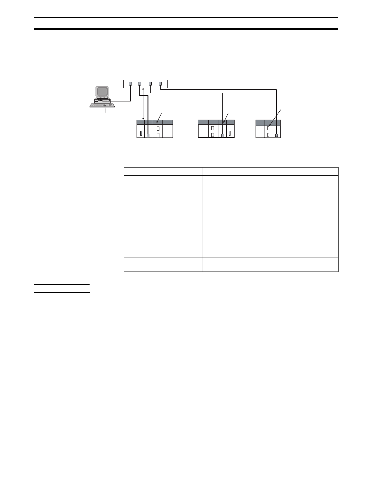
1-1 EtherNet/IP Unit Features
CX-One Support
Software
Ethernet (LAN) port
High-speed, High-capacity
Data Exchange through
Data Links
(3) Switching hub
(2) T wisted-pair cable
(1) Built-in EtherNet/IP port on
100 m
max.
(1) CS1W-EIP21 EtherNet/IP
Unit for CS-series
CS-series
PLC
EtherNet/IP System Configuration Example
(1) CJ1W-EIP21
EtherNet/IP Unit
CJ-series
PLC
CJ2 CPU Unit
(CJ2H-CPU@@-EIP/
CJ2M-CPU3@)
CJ-series
PLC
EtherNet/IP is an industrial multi-vendor network that uses Ether net components. The EtherNet/IP specifications are open standards managed by the
OD VA (Open DeviceNet Vendor Association), just like DeviceNet.
EtherNet/IP is not just a network between controllers; it is also used as a field
network. Since EtherNet/IP uses standard Ethernet technology, various general-purpose Ethernet devices can be used in the network. The EtherNet/IP
Unit and built-in EtherNet/IP port have the following features .
The EtherNet/IP protocol supports implicit communications, which allows
cyclic communications (called tag data links in this manual) with EtherNet/IP
devices. Data can be exchanged at high speed between Controllers and
devices, using high-volume tag sets (up to 640 words for the CJ2M and up to
184,832 words for other CPU Units) between PLCs.
Tag Data Link (Cyclic
Communications) Cycle
Time
Note The communications load to the nodes m ust be within the Units’ allo w ed com-
Communicating with FINS
Messages (FINS/TCP and
FINS/UDP)
Note There are no particular restrictions when sending FINS messages to OMRON
Network Connections with
Controller Link
Tag data links (cyclic communications) can operate at the cyclic period specified for each application, regardless of the number of nodes. Data is
exchanged over the network at the refresh cycle set for each connection, so
the communications refresh cycle will not increase even if the number of
nodes is increased, i.e., the synchronicity of the connection’s data is preserved.
Since the refresh cycle can be set for each connection, each application can
communicate at its ideal refresh cycle. For example, a processes interlocks
can be transferred at high speed while the production commands and the status monitor information are transferred at low speed.
munications bandwidth.
Data can be exchanged with other OMRON FA devices using SEND, RECV,
and CMND instruc tions from the ladder program, because Ether Net/IP supports OMRON’s standard FINS message communications services.
There are two kinds of message services, using UDP/IP and TCP/IP (called
FINS/UDP and FINS/TCP), allowing flexible data exchange for different applications.
Ethernet Units (CS1W-ETN21 or CJ1W-ETN21) in an Ethernet network.
Mutual connections of Controller Link and EtherNet/IP are also supported
(using the FINS communications service). The Controller Link connection
allows a PLC on the Controller Link networ k to be monitored from a PLC on
the EtherNet/IP network. Conversely, data can be exchanged with a PLC on
the EtherNet/IP network from a PLC on the Controller Link network.
2
Page 29

EtherNet/IP Unit Features Section 1-1
FTP Server A built-in FTP server is provided to enable transferring files in the PLC to and
from a host computer. This enables transferring large amounts of data from a
client without any additional ladder programming.
Automatic PLC Clock
Adjustment
Note A separate SNTP server is necessary to automatically adjust the PLC clocks.
Manage the Network with
an SNMP Manager
Note A separate SNMP mana ger is necessary for network managemen t.
Specify Servers with Host
Names
Note (1) A separate DNS server is necessary to use host names with the DNS cli-
Set Classless IP Address
with CIDR
Plentiful Troubleshooting
Functions
The clocks built into PLCs connected to Ethernet can be automatically
adjusted to the time of the clock in the SNTP ser ver. If all of the clocks in the
system are automatically adjusted to the same time , ti me stam ps can be use d
to analyze various production histories.
Internal status information from the EtherNet/IP Unit or built-in EtherNet/IP
port can be passed to network management software that uses an SNMP
manager.
DNS client functionality allows you to use host nam es instead of IP addresses
to specify SNTP ser vers a nd SNMP managers. This is useful, for ex ample,
when server IP addresses change for system revisions because the IP
addresses are automatically found when host names are used.
ent.
(2) The DNS server is specified directly using its IP address.
A subnet mask can be set to use clas sless IP addres ses, allowing more flexibility in address settings.
A variety of functions are provided to quickly identify and handle errors.
• Self-diagnosis at power ON
• PING command to check the connection with another node
• Error Log functions record the time of occurrence and other error details
Note The CIP (Common Industrial Protocol) is a shared industrial protocol for the
OSI application layer. The CIP is used in networks such as EtherNet/IP, ControlNet, and DeviceNet. Data can be routed easily between networks that are
based on the CIP, so a transparent network can be easily configured from the
field device level to the host level.
The CIP has the following advantages.
• Destination nodes are specified by a relative path, without fixed routing
tables.
• The CIP uses the producer/consumer model. Nodes in the network are
arranged on the same level and it is possible to communicate with
required devices whenever it is necessary.
The consumer node will receive data sent from a producer node when the
connection ID in the packet indicates that the node requires the data.
Since the producer can send the same data with the same characteristics
in a multicast (either multicast or unicast can be selected), the time
required for the transfer is fixed and not dependent on the number of consumer nodes.
3
Page 30
Devices Required for Constructing a Network Section 1-2
1-2 Devices Required for Constructing a Network
The basic configuration for an EtherNet/IP System consists of one switching
hub to which nodes are attached in star configuration using twisted-pair ca bl e.
CX-One Support
Software
Ethernet (LAN) port
(3) Switching hub
(2) T wisted-pair cable
(1) Built-in EtherNet/IP port on
100 m
max.
(1) CS1W-EIP21 EtherNet/IP
Unit for CS-series
CS-series
PLC
(1) CJ1W-EIP21
EtherNet/IP Unit
CJ-series
PLC
CJ2 CPU Unit
(CJ2H-CPU@@-EIP/
CJ2M-CPU3@)
CJ-series
PLC
The devices shown in the following table are required to configure a network
with CS1W-EIP21 and CJ1W -EIP21 Ethe rNet/IP Units or the b uilt-in EtherNet/
IP port in CJ2H-CPU@@-EIP/CJ2M-CPU3@ CPU Units.
Network device Contents
(1) CS1W-EIP21 EtherNet/IP
Units for CS-series PLCs,
CJ1W-EIP21 EtherNet/IP
Units for CJ-series PLCs,
or built-in EtherNet/IP port
in CJ2H-CPU@@-EIP/
CJ2M-CPU3@ CPU Units
(2) Twisted-pair cable The twisted-pair cable connects EtherNet/IP Units or
(3) Switching Hub This is a relay device that connects multiple nodes in
These are Communications Units or built-in ports
that connect a CS-series or CJ-series PLC to an EtherNet/IP network.
built-in EtherNet/IP ports to the switching hub, with
an RJ45 Modular Connector at each end.
Use an STP (shielded twisted-pair) cable of category
5, 5c, or higher.
a star-shaped LAN.
Recommended
Switching Hubs
For details on recommended devices for constructing a network, refer to 2-3-1
Recommended Network Devices.
Note If a repeater hub is used for EtherNet/IP tag data links (cyclic communica-
tions), the network’s communications load will increase, data collisions will
occur frequently, and stable communications will be impossible. Always use a
switching hub when using tag data links in the network.
1-3 Support Software Required to Construct a Network
This section describes the Support Software that is required to construct an
EtherNet/IP network. Make the tag data link settings and Unit setup settings
for the EtherNet/IP Unit or built-in EtherNet/IP port . Both of thes e settings are
stored in the EtherNet/IP Unit’s non-volatile memory (See note.). Support
Software is provided for each, as described below.
Note Unlike the Ethernet Units, the EtherNet/IP Unit’s TCP/IP settings are not
stored in the CPU Unit’s CPU Bus Unit System Setup Area. The settings are
stored in the EtherNet/IP Unit itself.
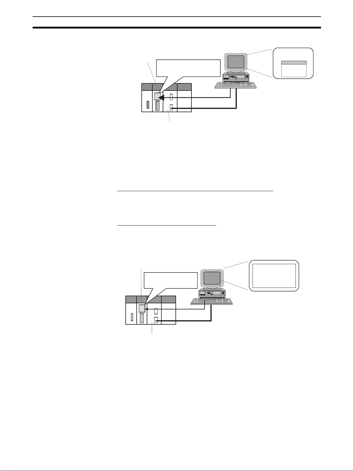
Unit Setup: CXProgrammer
The CX-Programmer is used to set basic parameters, such as the local IP
address of the EtherNet/IP Unit or built-in EtherNet/IP port and the subnet
mask. (The CX-Programmer is included in the CX-One.)
The CX-Programmer can also be used to check if data I/O is being performed
correctly for ta g data links.
4
Page 31
Support Software Required to Construct a Network Section 1-3
Computer
EtherNet/IP Unit
or built-in
EtherNet/IP port
Unit settings
(Built-in non-volatile memory)
CX-Programmer
Edit Parameters
Dialog Box
Tag Data Link Settings:
Network Configurator
CS/CJ-series CPU Unit
Refer to the CX-Programmer Operation Manual (Cat. No. W446) for info rma-
tion on the CX-Programmer.
The Network Configurator is used to set the tag data links for the EtherNet/IP
Unit or built-in EtherNet/IP port. (The Network Configurator is included in CXOne version 3.0 or higher.) The main functions of the Network Configurator
are given below.
1) Setting and Monitoring Tag Data Links (Connections)
The network device configuratio n a nd tag data links (co nne ction s) can be created and edited. After connecting to the netw o rk, the device configuration and
tag data link settings can be uploaded and monitored.
2) Multivendor Device Connections
EDS files can be installed and deleted to enable constructing, setting, and
managing networks that contain EtherNet/IP devices from other companies.
The IP addresses of EtherNet/IP devices can also be changed.
EtherNet/IP Unit
or built-in EtherNet/IP port
Tag Data Link Settings
(Built-in non-volatile memory)
Computer
Network Configurator
Edit Device
Parameters
Dialog Box
Routing Table Settings:
CX-Integrator
Transferred
CS/CJ-series CPU Unit
For details on the Network Configurator, refer to SECTION 6 Tag Data Link
Functions.
Propriety OMRON FINS network system can be constructed from OMRON
Communications Units. When FINS services are used, the CX-Integrator
allows you to set routing tables to define transmission paths. (The CX-Integrator is included in the CX-One.) If FINS services are not used, then routing
tables are not required.
5
Page 32

Communications Services Overview Section 1-4
Personal computer
running Windows
CX-Integrator
Routing table
EtherNet/IP Unit or
built-in EtherNet/IP port
Routing T ab le Area
CS/CJ-series CPU Unit
settings
Refer to the CX-Integrator Operation Manual (Cat. No. W464) for information
on the CX-Integrator.
1-4 Communications Services Overview
The following communications services are supported.
CIP (Common Industrial Protocol) Communications Services
CS1W-EIP21
CJ1W-EIP21
CJ2H-CPU@@-EIP
Total size of all tags ≤
184,832 words
Maximum size of 1 tag ≤ 722
words
(The maximum size is 721
words when the tag set
includes the PLC status.)
Number of registrable tags ≤
256
1) Tag Data Links (Cyclic Communications)
A program is not required to perform cyclic data exchang es with other devices
in the EtherNet/IP network.
Normally, the tag data links in an EtherNet/IP Unit or built-in EtherNet/IP port
are started by grouping the tags created with the Network Configurator into a
tag set, and establishing a connection with the target device using that group
of tags. One connection is used per group (tag set). Up to 32 connections fo r
the CJ2M and up to 256 connections for other CPU Units) can be registered.
The following table gives the tag and tag set specifications.
Tags Tag sets
CJ2M-CPU3@ CS1W-EIP21
CJ1W-EIP21
CJ2H-CPU@@-EIP
Total size of all tags ≤ 640
words
Maximum size of 1 tag ≤ 20
words
(The maximum size is 19
words when the tag set
includes the PLC status.)
Number of registrable tags ≤ 32Number of registrable ta g
Maximum size of 1 tag set ≤
722 words
(The maximum size is 721
words when the tag set
includes the PLC status.)
Number of tags per tag set ≤ 8
(7 tags/tag set when the tag set includes the PLC status)
Note Input and output variables cannot be combined.
sets ≤ 256
CJ2M-CPU3@
Maximum size of 1 tag set ≤
20 words
(The maximum size is 19
words when the tag set
includes the PLC status.)
Number of registrabl e ta g
sets ≤ 32
6
Page 33

Communications Services Overview Section 1-4
Connection information
• Target IP address
• Target tag set
• Originator tag set
• Packet interval (RPI)
Connection
Tag Set (Inputs)
Tag set name: S
P1_IN
PLC Status
Tag a
Tag b
Tag c
Data flow
Tag Set (Outputs)
Tag set name: S
P1_IN
PLC Status
Tag i
Tag ii
:
Tag g
Originator
device
EtherNet/IP
Target
device
Note In this example, a connection is established with the originator’s tag list con-
taining tags a to g (inputs), which are grouped in a tag set called SP1_IN, and
the target’s tag list containing tags i and ii (outpu ts), which are grouped in a
tag set called SP1_OUT.
2) Message Communications (Unconnected Message Service)
User-specified CIP commands can be sent to devices on the EtherNe t/IP net work. CIP commands, such as those for reading and writing data, can be sent
and their responses received by executing the CMND instruction from the CS/
CJ-series CPU Unit’s user program (without using a connection).
EtherNet/IP Unit
CS/CJ-series CPU Unit
CMND
CIP command
Response
Ethernet
(EtherNet/IP)
CIP messages (CIP commands and responses) can also be transferred to
another CIP-based network via the EtherNet/IP Unit or built-in EtherNet/IP
port using the CIP routing function for message commun ications.
In the CS/CJ Series, CIP routing is possible only through two EtherNet/IP
Units or built-in EtherNet/IP port.
7
Page 34

Communications Services Overview Section 1-4
t
EtherNet/IP
FINS
Communications
Service
CS/CJ-series CPU Unit
EtherNet/IP Unit
EtherNet/IP Unit
Ethernet
(EtherNet/IP), etc.
FINS commands can be sent to or received from other PLCs or computers on
the same Ethernet network by executing SEND(090), RECV(098), or
CMND(490) instructions in the ladder diagram program. This enables various
control operations such as the reading and writing of I/O memory between
PLCs, mode changes, an d file memory operations.
Note There are no particular restrictions when sending FINS messages to OMRON
Ethernet Units (CS1W-ETN21 or CJ1W-ETN21) in an Ethernet network.
Ethernet (EtherNet/IP)
UDP or TCP
IP
CS/CJ-series CPU
Unit
FINS IP FINS
UDP or TCP
EtherNet/IP Unit
User program
SEND(090),
RECV(098), or
CMND(490)
instruction
Ethernet Unit
EtherNet/IP Uni
Various control operations (such as the reading and writing of I/O memory
between PLCs, mode changes, and file memor y operations) can be executed
from the host computer by sending the corresponding FINS command with a
UDP/IP or TCP/IP header attached.
For ex ample , it is possib le to co nnect online via Ethernet from FINS comm unications applications such as the CX-Programmer, and to perform remote programming and monitoring. (See note.)
Note Use CX-Programmer v ersion 4. 0 to use TCP/IP. For lo w er v ersio ns of CX-Pro-
grammer, FinsGateway Version 2003 or higher is required to use TCP/IP.
8
Page 35

Communications Services Overview Section 1-4
Ethernet (EtherNet/IP)
UDP or TCP
IP FINS
CS/CJ-series CPU
Unit
EtherNet/IP Unit
The FINS gateway function enables access to PLCs on not only the same
Ethernet network but on various other networks, including SYSMA C LINK and
Controller Link.
9
Page 36

Network Configurator Overview Section 1-5
1-5 Network Configurator Overview
1-5-1 Overview
The Network Configurator Ver. 3.0 or higher is a software package designed
for building, setting, and controlling a multi-vendor EtherNet/IP Networ k using
OMRON's EtherNet/IP. It is included in CX-One version 4.0 or higher. The
Network Configurator provides th e f ollo wing fu nctions for building, setting, and
controlling EtherNet/IP.
Network Control The Network configuration can be created and edited regardless of whether
the Network Configurator is online or offline. The Network configuration can
be read from a file or the network.
Hardware (EDS File)
EDS files used by the Network Configurator can be installed and deleted.
Control
1-5-2 Network Configurator Requirements
Item Specification
Operating environment Refer to the CX-One Setup Manual (W463).
CXONE-AL@@C-V4/CXONE-AL@@D-V4
Network
connection
method
Location on Network A single node address is used (only when directly connected to EtherNet/IP).
Number of Units that can be
connected to Network
Main func-
tions
Supported file formats Configurator network configuration files (*.nvf)
Serial interface CPU Unit’s Peripheral or RS-232C port CPU Unit’s USB or RS-232C port
Ethernet interface EtherNet/IP Unit’s Ethernet port CPU Unit’s Ethernet port
A single Network Configurator per network (More than one Configurator cannot be
used in the same system.)
Network control
functions
Hardware control
functions
• The network configuration can be created and edited regardless of whether the Network Configurator is online or offline.
•The network configuration can be read from a file or the network.
The EDS files used by the Network Configurator can be installed and deleted.
Configuration files (*.ncf) created using the Network Configurator for EtherNet/IP
(version 2) can be imported by selecting External Data - Import from the File
Menu.
CS1/CJ1 CJ2
EtherNet/IP Unit’s Ethernet port
10
Page 37

Network Configurator Overview Section 1-5
1-5-3 Precautions When Using the Network Configurator
Only an OMRON EtherNet/IP Unit can be set as the originator for a connection using the Network Configurator.
• The Network Configurator can be connected to the EtherNet/IP network
through the follo wing ports:
• CS1/CJ1-series CPU Unit’s serial port (peripheral or RS-232C) or
Ethernet port on EtherNet/IP Unit
• CJ2-series CPU Unit’s serial port (USB or RS-232C), Ethernet port on
EtherNet/IP Unit or built-in EtherNet/IP port
• The Network Configurator can be connected directly to the EtherNet/ IP
network from the computer’s Ethernet por t. When connecting directly to
the EtherNet/IP network, an Ethernet port must be set up in the computer
in advance. In this case, the Network Configurator will be connected to
the EtherNet/IP network as a single node. If there isn’t an unused node
address availab le , the Netw ork Configurator can ’t be connected d irectly to
the EtherNet/IP network.
11
Page 38

Network Configurator Overview Section 1-5
12
Page 39

SECTION 2
Unit Specifications
This section provides the specifications of EtherNet/IP Units and introduces recommended network configuration devices.
2-1 EtherNet/IP Unit and Built-in EtherNet/IP Port Specifications . . . . . . . . . . . 14
2-1-1 General Specifications . . . . . . . . . . . . . . . . . . . . . . . . . . . . . . . . . . . 14
2-1-2 Unit Specifications . . . . . . . . . . . . . . . . . . . . . . . . . . . . . . . . . . . . . . 14
2-1-3 Communications Specifications . . . . . . . . . . . . . . . . . . . . . . . . . . . . 17
2-1-4 Dimensions. . . . . . . . . . . . . . . . . . . . . . . . . . . . . . . . . . . . . . . . . . . . 19
2-1-5 Software Configuration. . . . . . . . . . . . . . . . . . . . . . . . . . . . . . . . . . . 20
2-2 Nomenclature and Functions . . . . . . . . . . . . . . . . . . . . . . . . . . . . . . . . . . . . . 21
2-2-1 Nomenclature and Functions . . . . . . . . . . . . . . . . . . . . . . . . . . . . . . 21
2-2-2 Switch Settings . . . . . . . . . . . . . . . . . . . . . . . . . . . . . . . . . . . . . . . . . 26
2-3 Selecting the Network Devices. . . . . . . . . . . . . . . . . . . . . . . . . . . . . . . . . . . . 28
2-3-1 Recommended Network Devices . . . . . . . . . . . . . . . . . . . . . . . . . . . 28
2-3-2 Network Devices Manufactured by OMRON . . . . . . . . . . . . . . . . . 28
2-3-3 Switching Hub Types . . . . . . . . . . . . . . . . . . . . . . . . . . . . . . . . . . . . 28
2-3-4 Switching Hub Functions . . . . . . . . . . . . . . . . . . . . . . . . . . . . . . . . . 29
2-3-5 Precautions When Selecting a Switching Hub . . . . . . . . . . . . . . . . . 29
13
Page 40

EtherNet/IP Unit and Built-in EtherNet/IP Port Specifications Section 2-1
2-1 EtherNet/IP Unit and Built-in EtherNet/IP Port
Specifications
2-1-1 General Specifications
The general specifications conform to those of th e CS-series and CJ-series
PLCs.
2-1-2 Unit Specifications
CS-series EtherNet/IP Units
Item Specifications
Model number CS1W-EIP21
Type 100Base-TX (See note.)
Applicable PLCs CS-series PLCs
Unit classification CS-series CPU Bus Unit
Mounting location CPU Rack or Expansion Rack
Number of Units that can be
mounted
CPU Unit
words used
Non-volatile memory within EtherNet/IP Unit (See note.)
Transfer
specifications
Current consumption (Unit) 410 mA max. at 5 V DC
Weight 171 g max.
Dimensions 35 × 130 × 101 mm (W × H × D)
Other general specifications Other specifications conform to the general specifications of the CS-series
Allocated CIO Area
words (CPU Bus Unit
words)
Allocated DM Area
words (CPU Bus Unit
words)
User-set area Any usable data area words
CPU Bus Unit System
Setup
Media access method CSMA/CD
Modulation method Baseband
Transmission paths Star form
Baud rate 100 Mbit/s (100Base-TX)
Transmission media Shielded twisted-pair (STP) cable
Transmission distance 100 m (distance between hub and node)
Number of cascade
connections
8 max. (including Expansion Racks)
25 words/Unit (one unit number’s words)
These words contain control bits and flags, the target node PLC’s operating and
error information, Unit status, communications status, registered/normal target
node information, and FINS/TCP connection status.
100 words/Unit (one unit number’s words)
These words contain the IP address display/setting area
Target node PLC’s operating and error information, and registered/normal target
node information
Not used.
The following settings are stored in the EtherNet/IP Unit’s non-volatile memory.
Note Unlike the regular Ethernet Units, the CPU Bus Unit Setup Area in the CPU
Unit is not used for these settings.
1. Unit setup (communications settings for the EtherNet/IP Unit, such as the IP address, DNS server settings, host name, baud rate, FINS/UDP settings, and FINS/
TCP settings)
2. Tag data link settings (device parameters)
Categories: 100 Ω at 5, 5e
There is no limitation when a switching hub is used.
14
Note If tag data links are being used, use 100Base-TX. Otherwise, 10Base-T can
be used, but this is not recommended.
Page 41

EtherNet/IP Unit and Built-in EtherNet/IP Port Specifications Section 2-1
CJ-series EtherNet/IP Unit
Item Specifications
Model number CJ1W-EIP21
Type 100Base-TX (See note.)
Applicable PLCs CJ-series PLCs
Unit classification CJ-series CPU Bus Unit
Mounting location CPU Rack or Expansion Rack
Number of Units that can be
mounted
CPU Unit
words used
Non-volatile memory within EtherNet/IP Unit (See note.)
Transfer
specifications
Current consumption (Unit) 410 mA max. at 5 V DC
Weight 94 g max.
Dimensions 31 × 90 × 65 mm (W × H × D)
Other general specifications Other specifications conform to the general specifications of the CJ-series.
Allocated CIO Area
words (CPU Bus
Unit words)
Allocated DM Area
words (CPU Bus
Unit words)
User-set area An y usable data area words
CPU Bus Unit System Setup
Media access
method
Modulation method Baseband
Transmission paths Star form
Baud rate 100 Mbit/s (100Base-TX)
Transmission media Shielded twisted-pair (STP) cable
Transmission distance
Number of cascade
connections
8 max. (including Expansion Racks)
Note Up to seven EtherNet/IP Units can be connected to a CJ2H-CPU@@-EIP CPU
Unit. Up to two EtherNet/IP Units can be connected to a CJ2M CPU Unit.
25 words/Unit (one unit number’s words)
These words contain control bits and flags, the target node PLC’s opera ting and error
information, Unit status, communications status, registered/normal target node information, and FINS/TCP connection status.
100 words/Unit (one unit number’s words)
These words contain the IP address display/setting area.
Target node PLC’s operating and error information, and registered/normal ta rget
node information
Not used.
The following settings are stored in the EtherNet/IP Unit’s non-volatile memory.
Note Unlike the regular Ethernet Units, the CPU Bus Unit Setup Area in the CPU
Unit is not used for these settings.
1. Unit Setup (communications settings for the EtherNet/IP Unit, such as the IP ad-
dress, DNS server settings, host name, baud rate, FINS/UDP settings, and FINS/
TCP settings)
2. Tag data link settings (device parameters)
CSMA/CD
Categories: 100 Ω at 5, 5e
100 m (distance between hub and node)
There is no limitation when a switching hub is used.
Note If tag data links are being used, use 100Base-TX. Otherwise, 10Base-T can
be used, but this is not recommended.
15
Page 42

EtherNet/IP Unit and Built-in EtherNet/IP Port Specifications Section 2-1
CJ2 CPU Built-in EtherNet/IP Port
Item Specifications
Model number CJ2H-CPU@@-EIP CJ2M-CPU3@
Type 100Base-TX (See note.)
Unit classification CJ2 CPU Unit built-in port (CJ2 CPU Bus Unit)
CPU Unit
words used
Non-volatile memory for the CJ2
built-in EtherNet/IP port
Transfer
specifications
Current consumption (Unit) For CJ2 CPU Units, refer to the CJ2 CPU Hardware Operation Manual (W472).
Weight
Dimensions
Other general specifications Other specifications conform to the general specifications of the CJ2 or built-in Ether-
Allocated CIO Area
words (CPU Bus
Unit words)
Allocated DM Area
words (CPU Bus
Unit words)
User-set area An y usable data area words
CPU Bus Unit System Setup
Media access
method
Modulation method Baseband
Transmission paths Star form
Baud rate 100 Mbit/s (100Base-TX)
Transmission media Shielded twisted-pair (STP) cable
Transmission distance
Number of cascade
connections
25 words/Unit (one unit number’s words)
These words contain control bits and flags, the target node PLC’s opera ting and error
information, Unit status, communications status, registered/normal target node information, and FINS/TCP connection status.
100 words/Unit (one unit number’s words)
These words contain the IP address display/setting area.
Target node PLC’s operating and error information, and registered/normal ta rget
node information
Not used.
The following settings are stored in the non-volatile memory for the built-in EtherNet/
IP port.
Note Unlike the regular Ethernet Units, the CPU Bus Unit Setup Area in the CPU
Unit is not used for these settings.
1. Unit Setup (communications settings for the built-i n EtherNet/IP port, such as the
IP address, DNS server settings, host name, baud rate, FINS/UDP settings, and
FINS/TCP settings)
2. Tag data link settings (device parameters)
CSMA/CD
Categories: 100 Ω at 5, 5e
100 m (distance between hub and node)
There is no limitation when a switching hub is used.
Net/IP port CJ2 CPU Unit.
16
Note If tag data links are being used, use 100Base-TX. Otherwise, 10Base-T can
be used, but this is not recommended.
Page 43

EtherNet/IP Unit and Built-in EtherNet/IP Port Specifications Section 2-1
2-1-3 Communications Specifications
Item CS1/CJ1 CJ2H CJ2M
CIP
service
Tag data
links
(Cyclic
communications)
Number of connections 256 32
Packet interval (refresh
cycle)
Allowed communications bandwidth per
Unit
Number of tags that
can be registered
Tag types CIO Area, DM Area, EM Area, Holding Area, Work Area, and network
Number of tags per
connection (= 1 tag
set)
Maximum link data size
per node
Maximum data size per
connection
Number of registrable
tag sets
Maximum size of 1 tag
set
Maximum number of
tags that can be
refreshed per CPU Unit
cycle (See note 3.)
Data that can be
refreshed per CPU Unit
cycle (See note 3.)
Changing tag data link
parameters during
operation
Multicast packet filter
function (See note 6.)
0.5 to 10,000 ms (in 0.5-ms units)
Can be set independently for each connection.
(Data is refreshed over the network at the preset
interval and does not depend on the number of
nodes.)
6000 pps (See note 1.)
Note Including the heartbeat.
256 32
symbols (See note 8.)
8 (7 tags when the tag set contains the PLC status)
184,832 words 640 words
252 words or 722 words (See note 2.)
Note Data synchronicity is maintained within
each connection.
256
(1 connection = 1 tag set)
722 words
(The PLC status uses 1 word when the tag set
contains the PLC status.)
Output/Transmission
(CPU → EtherNet/IP):
19
Input/Reception
(EtherNet/IP → CPU):
20 (See note 4.)
Output/Transmission
(CPU → EtherNet/IP):
7,405 words
Input/Reception
(EtherNet/IP → CPU):
7,405 words
Supported (See note 5.)
Supported
Output/Transmission
(CPU → EtherNet/IP):
256
Input/Reception
(EtherNet/IP → CPU):
256
Output/Transmission
(CPU → EtherNet/IP):
6,432 words
Input/Reception
(EtherNet/IP → CPU):
6,432 words
1 to 10,000 ms (in 0.5ms units)
Can be set independently for each connection.
(Data is refreshed over
the network at the preset interval and does
not depend on the
number of nodes.)
3000 pps (See note 1.)
Note Including the
heartbeat.
20 words
Note Data synchronic-
ity is maintained
within each connection.
32
(1 connection = 1 tag
set)
20 words
(The PLC status uses 1
word when the tag set
contains the PLC status.)
Output/Transmission
(CPU → EtherNet/IP):
32
Input/Reception
(EtherNet/IP → CPU):
32
Output/Transmission
(CPU → EtherNet/IP):
640 words
Input/Reception
(EtherNet/IP → CPU):
640 words
17
Page 44

EtherNet/IP Unit and Built-in EtherNet/IP Port Specifications Section 2-1
Item CS1/CJ1 CJ2H CJ2M
CIP
service
FINS service
(See note 7.)
SNMP Agent SNMPv1, SNMPv2c
EtherNet/IP conformance test Conforms to A5
Ethernet interface 10BASE-T or 100BASE-TX
Explicit
messaging
Class 3 (connected) Number of connections: 128
UCMM (unconnected) Number of clients that can communicate at one
time:
32 max.
Number of servers that can communicate at one
time:
32 max.
CIP routing CS1W-EIP21
CJ1W-EIP21
CJ2H-CPU@@-EIP
CJ2M-CPU3@
FINS/UDP Supported
FINS/TCP 16 connections max.
MIB MIB-II
Auto Negotiation or fixed settings
Number of clients that
can communicate at
one time:
16 max.
Number of servers that
can communicate at
one time:
16 max.
Note (1) In this case, pps means “packets per second” and indicates the number
of packets that can be processed in one second.
(2) To use 505 to 1,444 bytes as the data size, the system must support the
Large Forward Open standard (an optional CIP specification). The SYSMAC CS/CJ-series Units support this standard, but before connecting to
nodes of other companies, confirm that those devices also support it.
(3) If the maximum data size is exceeded, the data refreshing with the CPU
Unit will extend over two or more cycles.
(4) If status layout is selected in the user settings, the maximum number of
tags that can be received is 19 tags.
(5) If parameters are changed in the EtherNet/IP Unit, however, the Ether-
Net/IP Unit will be restarted. When other nodes are communicating with
the affected node, the communications will temporarily time out and automatically recover later.
(6) Because the EtherNet/IP Unit is equipped with an IGMP client (version
2), unnecessary multicast packets can be filtered by using a switching
hub that supports IGMP snooping.
(7) The EtherNet/IP Unit uses the TCP/UDP port numbers shown in the fol-
lowing table.
Service Protocol Port number Remarks
Tag data links UDP 2222 Fixed value
Class 3, UCMM TCP/UDP 44818
DNS UDP 53
FINS/UDP service UDP 9600 Port numbers in the Unit
FINS/TCP service TCP 9600
FTP TCP 20, 21
SNTP UDP 123
SNMP UDP 161
SNMP trap UDP 162
Setup can be changed with
the CX-Programmer.
18
(8) Network symbols can be used only with a CJ2H-CPU6@-EIP or CJ2M-
CPU3@ CPU Unit.
Page 45

EtherNet/IP Unit and Built-in EtherNet/IP Port Specifications Section 2-1
2-1-4 Dimensions
CS1W-EIP21
EIP21
MS
NS
COMM
100M
10M
UNIT
0
NO.
NODE
1
0
130 mm
NO.
IP ADDRESS
192.168.250.1
SUBNET MASK
255.255.255.0
100BASE-TX
×16
10BASE-T
0
1
×16
101 mm35 mm
CJ1W-EIP21
CJ2H-CPU@@-EIP
90 mm
2.7 mm
31 mm
EIP21
5
4
6
3
7
2
8
1
9
0
A
F
B
E
C
D
IP ADDRESS
192.168.250.1
SUBNET MASK
255.255.255.0
100BASE-TX
10BASE-T
65 mm
MS
NS
COMM
100M
10M
5
4
UNIT
6
3
7
2
8
1
9
0
A
F
No.
B
E
C
D
5
4
NODE
6
3
7
2
8
1
9
0
A
F
No.
B
E
C
D
0
1
x16
x16
66.2 mm
90 mm
2.7 mm
79.8 mm
65 mm
74.5 mm
19
Page 46

EtherNet/IP Unit and Built-in EtherNet/IP Port Specifications Section 2-1
CJ2M-CPU3@
2.7 mm
90 mm
2.7 mm
2-1-5 Software Configuration
Memory Card/
EM file memory
FINS Cyclic
62 mm
Interface with CPU Unit
FINS
encapsulization
76.16 mm
75 mm
84.5 mm
FINSFINS
FTP
FINS Service
(FINS/UDP and FINS/TCP)
TCP
Tag data link function Explicit messaging
IP
LAN controller driver
LAN controller
CIP
Encapsulation
UDP
Automatic
clock adjustment
ARP IGMP
ICMP
20
Page 47

Nomenclature and Functions Section 2-2
2-2 Nomenclature and Functions
2-2-1 Nomenclature and Functions
CS1W-EIP21
EIP21
MS
CJ1W-EIP21
NS
COMM
100M
10M
UNIT
NO.
NODE
0
NO.
1
×16
IP ADDRESS
192.168.250.1
SUBNET MASK
255.255.255.0
100BASE-TX
10BASE-T
0
1
0
×16
LED Indicators
Unit number
setting switch
Node address
setting switches
Label showing
IP address
Ethernet
connector
Backplane
Connector
EIP21
5
4
6
3
7
2
8
1
9
0
A
F
B
E
C
D
x16
IP ADDRESS
192.168.250.1
SUBNET MASK
255.255.255.0
100BASE-TX
10BASE-T
MS
NS
COMM
100M
10M
5
UNIT
4
6
3
7
2
8
1
9
0
A
F
No.
B
E
C
D
5
4
NODE
6
3
7
2
8
1
9
0
A
F
No.
B
E
C
D
1
x16
0
LED Indicators
Unit number
setting switch
Node address
setting switches
Label showing
IP address
Ethernet
connector
21
Page 48

Nomenclature and Functions Section 2-2
)
Built-in EtherNet/IP Port in CJ2H-CPU@@-EIP
LED Indicators
Unit number
setting switch
Node address
setting switches
Label showing
IP address
Ethernet
connector
Built-in EtherNet/IP Port in CJ2M-CPU3@
LED Indicators
Unit number
setting switch
Node address
setting switches
Label showing
IP address
Ethernet
connector
Ethernet Address Notation A specific Ethernet address is allocated to all devices connected to the Ether-
net network. The EtherNet/IP Unit’s address is listed in 12-digit hexadecimal
on the right side of the Unit.
CS1W-EIP21
ETHERNET/IP UNIT
Lot No.
OMRON Corporation MADE IN JAPAN
@@@@@@@@@@@@
Ethernet Address
Ethernet address (12 digits
Note (1) The Ethernet Address can also be checked with the CONTROLLER
DAT A READ command. F or details, ref er to Appendix E FINS Commands
Addressed to EtherNet/IP Units or Built-in EtherNet/IP Ports.
(2) An IP address label is included with the EtherNet/IP Unit, so the user can
record the user-set IP address and subnet mask on the label, and affix
the label to the front of the Unit. When this label is affixed to the front of
the Unit, it is easy to confirm the Unit’s IP address and subnet mask.
22
Page 49

Nomenclature and Functions Section 2-2
EIP21
COMM
100M
5
4
3
2
1
0
F
E
C
D
6
B
MS
NS
10M
7
8
9
A
UNIT
No.
Example label
IP ADDRESS
192.168.250.1
SUBNET MASK
255.255.255.0
5
4
5
4
6
3
7
2
8
1
9
0
A
F
B
E
C
D
x16
IP ADDRESS
192.168.250.1
SUBNET MASK
255.255.255.0
100BASE-TX
10BASE-T
Indicators A EtherNet/IP Units or built-in EtherNet/IP port is equipped with the following
indicators that indicate the operating status of the node itself and the overall
network.
CS1W-EIP21
NODE
6
3
7
2
8
1
9
0
A
F
No.
B
E
C
D
x16
0
1
Affix the label on the front of the
EtherNet/IP Unit, between the
node address switches and the
Ethernet connector.
Status Indicators: MS, NS,
COMM, 100M, and 10M
EIP21
MS
NS
COMM
100M
10M
CJ1W-EIP21, CJ2H-CPU@@-EIP, and CJ2M-CPU3@
EIP
21
MS
NS
COMM
100M
10M
The MS (Module Status) indicator indicates the status of the node itself and
the NS (Network Status) indicator indicates the status of the network.
The COMM, 100M, and 10M indicators indicate the status of Ethernet communications.
The MS and NS indicators can be green or red. The COMM, 100M, and 10M
indicators are yellow. These indicators can be lit, flashing, or not lit. The following table shows t he meaning of these indicator conditions.
Refer to SECTION 14 Troubleshooting and Error Processing for details on
using these indicators for troubleshooting.
23
Page 50

Nomenclature and Functions Section 2-2
Indicator Name Color LED status Indicated operating status
MS Module Status Red Lit Fatal error
Flashing Re coverable error
Green Lit Normal
--- Not lit Power supply OFF
NS Network Status Red Lit Fatal error
Flashing Re coverable error
Green Lit Tag data link and message connections established
Flashing Tag data link and message connections not established
--- Not lit Offline or power supply OFF
COMM Communication Yellow Lit Transferring data
Not lit Not transferring data
100M 100 Mbps Yellow Lit 100BASE-TX link established
Not lit 100BASE-TX link not established
10M 10 Mbps Yellow Lit 10BASE-TX link established
Not lit 10BASE-TX link not established
Seven-segment Display When the power is turned ON (or the Unit is restarted), all of the segments will
flash twice, the IP address set in the EtherNet/IP Unit or built-in EtherNet/IP
port will be displayed on the 7-segment display just once, from right to left.
Afterwards, the r ightmost 8 bits of the IP address is displayed in hexadecimal
during normal operation.
Example 1: Displaying IP Address 192.168.250.10
The IP address is displayed in decimal, flowing from right to left.
24
If the Unit is operating normally, the last digit of the
Unit's IP address is displayed in hexadecimal.
Flashing: The tag data link is stopped.
Lit: The tag data link is operating.
Page 51

Nomenclature and Functions Section 2-2
If an error occurs, the error code will be displayed alternately with the rightmost byte of the affected device’s IP address. For details on error codes, refer
to SECTION 14 Troubleshooting and Error Processing.
Displaying Multiple Error Sources
• A d6 error (failed to establish connection) occurred with IP address
192.168.250.8.
• A d6 error (failed to establish connection) occurred with IP address
192.168.250.9.
• A d5 error (verification error, target nonexistent) occurred with IP ad dress
192.168.250.64.
• A C6 error (multiple switches ON) and EA error (EtherNet/IP expansion
setting error) occurred at the local EtherNet/IP Unit or built-in EtherNet/IP
port, IP address 192.168.250.10.
The error code is displayed and then the last digit of the target node's
IP address is displayed in hexadecimal.
Displays errors that occurred
within the Unit.
The last digit of the Unit's IP address
is displayed in hexadecimal.
• There is no particular priority to the order in which the errors are displayed. All of the errors are displayed repeatedly in order.
25
Page 52

Nomenclature and Functions Section 2-2
F
E
D
C
B
A
9
8
7
6
5
4
3
2
1
0
Right and Left Dot LEDs
If an error occurred in two or mor e devices with the same rightmost byte in
their IP addresses, the Right Dot LED will be lit while the devices’ error is
being displayed.
Example: Displaying the Following Errors
• A d6 error (failed to establish connection) occurred with IP address
10.0.1.8.
• A d6 error (failed to establish connection) occurred with IP address
10.0.2.8.
2-2-2 Switch Settings
Unit Number Setting
Switch
Note (1) Use a small screwdriver to make the setting, and be sure not to damage
The Unit Number Setting Switch sets the unit number of the EtherNet /IP Unit
or built-in EtherNet/IP port as a CPU Bus Unit. The unit number determines
which data area words are allocated to the Unit to conta in data such as control bits, flags, stat us information, and connection information.
Note The unit number is factory-set to 0.
The unit number can be set to any number in the setting range (0 to F), as
long as the same number is not set on another CPU Bus Unit in the same
PLC.
Setting method Setting range
One-digit hexadecimal 0 to F
the rotary switch.
(2) Always t urn OFF the PL C’s power supply before setting the unit number.
(3) The unit number is factory-set to 0.
(4) If the same unit number is set on more than one CPU Bus Unit mounted
in a PLC, a unit number duplication error will occur in the PLC and the
EtherNet/IP Unit or built-in EtherNet/IP port will not be able to start oper-
ating.
26
Page 53

Nomenclature and Functions Section 2-2
F
E
D
C
B
A
9
8
7
6
5
4
3
2
1
0
0
F
E
D
C
B
A
9
8
7
6
5
4
3
2
1
Node Address Setting
Switch
Note If the node addres s setting is changed during operation, the MS Indicator will
The Node Address Setting Switch sets the node address of the EtherNet/IP
Unit or built-in EtherNet/IP port.
X161X16
Setting method Setting range
Two-digit hexadecimal 01 to FE
Note The node address is factory-set to 01. With the default settings, the values set
on these switches become the last two digits of the local IP address of the EtherNet/IP Unit or built-in EtherNet/IP port.
Default IP address = 192.168.250.node address
With the factory-default node address setting of 01, the default IP address is
192.168.250.1.
0
The node address can be set to any number in the setting range (01 to FE),
as long as the same address is not set on another node in the network.
flash red.
27
Page 54

Selecting the Network Devices Section 2-3
2-3 Selecting the Network Devices
2-3-1 Recommended Network Devices
The following table shows the devices recommended for use with the EtherNet/IP.
Part Maker Model number Inquires
Switching
Hub
Twisted-pair
cable
Connectors
(Modular
plug)
Boots Tsuko Company MK boot (IV) LB Tsuko Company Japan Headquar-
Cisco Systems, Inc. Consult the manufacturer. Cisco Systems, Inc. Main Corpo-
rate HQ
Contec USA, Inc. Consult the manufacturer. CONTEC USA Inc.
Phoenix Contact Consult the manufacturer. Phoenix Contact USA Customer
Service
100BASE-TX
Fujikura F-LINK-E 0.5mm × 4P Fujikura America, Inc.
EtherNet/IP compliant cable --STP Plug
Panduit Corporation MPS588 Panduit Corporation US Headquar-
ters
ters
Note (1) Always use a switching hub when using tag data links in the network.
(2) If a repeater hub is used for EtherNet/IP tag data links (cyclic communi-
cations), the network’s communications load will increase, data collisions
will occur frequently, and stable communications will be impossible.
2-3-2 Network Devices Manufactured by OMRON
The following networ k devices are manufactured by OMRON for EtherNet/IP
networks.
Name Model Function Number of
Switching Hub W4S1-03B Packet priority control (QoS):
EtherNet/IP control data priority
W4S1-05B 5 None
W4S1-05C 5 Provided.
Failure detection: Broadcast
storm, LSI error detection, 10/
100Base-TX, Auto-Negotiation
2-3-3 Switching Hub Types
Unmanaged Layer 2 (L2)
Switching Hubs
Managed Layer 2 (L2)
Switching Hubs
These switching hubs use the Ethernet MAC address to switch ports. Ordinary switching hubs have this function. Switching hub functions and settings
cannot be changed.
These switching hubs use the Ethe rnet address to switch p orts. Switching hub
functions and settings can be chan ged usin g specia l soft ware tools for switching hubs running on a network node. Analytical data can also be collected.
These switching hubs provide more-advanced functions that unmanaged
layer 2 switching hubs.
Error detection
ports
3None
output
28
Page 55

Selecting the Network Devices Section 2-3
2-3-4 Switching Hub Functions
This section describes the switching hu b functions that are important when
using an EtherNet/IP network. When using an EtherNet/IP Unit, set the following two functions.
• Multicast filtering
• QoS (Quality of Service) for TCP/UDP port numbers (L4)
Multicast Filtering Multicast filtering transfers multicast packets to the specific nodes only. This
function is implemented in the switching hub as IGMP Snooping or GMRP.
“Specific nodes” are nodes equipped with an IGMP client that have made
transfer requests to the switching hub. (OMRON EtherNet/IP Units are
equipped with an IGMP client.)
When the hub does not use multicast filtering, m ulticast packets are sent to all
nodes, just like broadcast packets, which increases the traffic in the network.
Settings must be made in the switching hub to enable this function.
There must be enough multicast filters for the network being used.
QoS (Quality of Service)
Function for TCP/UDP
Port Numbers (L4)
Note If the Network Configurator is used to set the connection type in the connec-
This function controls the priority of packe t transmissions so that packets can
be sent with higher priority to a particular IP address or TCP (UDP) port. The
TCP and UDP protocols are called transport layer protocols, leading to the
name L4 (layer 4) QoS function.
When tag data links and message communicat ions are executed on the same
network, tag data links can be sent at higher priority to prevent problems such
as transmission delays due to message communications traffic and packet
losses due to buffer overflow. Settings must be made in the switching hub to
enable this function and give higher priority to tag data link packets.
Support for the above two functions is as follows for the different types of
switching hubs.
Hub Multicast
filtering
Unmanaged L2 switching hub None None --Managed L2 switching hub Provided. Provided. Both functions must
OMRON W4S1-series Switching
Hubs
None Provided. L4 QoS is set using
L4 QoS Remarks
be set with a special
software tool.
a switch. No software tool is necessary.
tion settings to a multicast connection, multicast packets will be used. If the
connection type is set to a point-to-point connection, m ult icast p ackets will not
be used.
2-3-5 Precautions When Selecting a Switching Hub
The functions supported by the switching hub may affect tag data link transmission delays and the configur ation. In addition , if the s witching hub suppo rts
advanced functions, special settings are required for those functions.
29
Page 56

Selecting the Network Devices Section 2-3
When selecting a switching hub, it is necessary to consider whether the
switching hub will be selected based on the kind and amount of communications that will be performed in the network or the kind of switching hub that y ou
want to use. Refer to the following precautions when selecting a switching
hub.
Refer to 10-2 Adjusting the Communications Load to estimate the communi-
cations load for tag data links.
Selecting the Switching Hub Based on the Types of Network Communications
Executing Tag Data Links
Only
Executing Tag Data Links
and Message
Communications
We recommend using an L2 switching hub without multicast filtering or an L2
switching hub with multicast filtering.
Using an L2 switching hub with multicast filtering prevents increased traffic
due to unnecessary multicast packets, so the tag data links can operate at
higher speed. If either of the following conditions exists, the amount traffic will
be the same for both kinds of L2 switching hubs (with or without multicast filtering).
• The tag data links are set to share the same dat a with all nodes in the ne twork. (The multicast packets are transferred to all nodes in the network,
just like a broadcast.)
• The tag data link settings are all one-to-one (unicast) and multicast packets cannot be used.
If multicast filters are being used, settings must be made in the switching hub.
There must be enough multicast filters for all of the networks being used.
We recommend using an L2 s witchin g hub with m ulticast filtering and L4 QoS .
By setting tag data links for higher-priority transmission, it is possible to pre-
vent problems such as transmission delays due to message communications
traffic and packet losses due to buffer overflow. Settings must be made in the
switching hub to enable this function and give higher priority to tag data link
packets.
Special settings must be made in the switching hub when using the multicast
filtering function and L4 QoS function.
Selecting the Switching Hub Based on the Hub’s Supported Functions
L2 Switching Hub without
Multicast Filtering
L2 Switching Hub with
Multicast Filtering
We recommend this kind of switching hub when only tag data links are executed and any of the following conditions is met.
• The tag data links are set to share the same dat a with all nodes in the ne twork. (The multicast packets are transferred to all nodes in the network,
just like a broadcast.)
• The tag data link settings are all one-to-one (unicast) and multicast packets cannot be used.
• There is little traffic in the tag data links.
No special settings are required for an L2 switching hub without multicast filtering.
We recommend this kind of switching hub when only tag data links are executed and the following condition is met.
• There are many 1:N links (where N represents some number of nodes in
the network) in the tag data link settings, i.e., there are many multicast
packets used, or there is heavy traffic in the tag data links.
Special settings are required for an L2 switching hub with multicast filtering.
There must be enough multicast filters for the network being used.
30
Page 57

Selecting the Network Devices Section 2-3
L3 Switching Hub with
Multicast Filtering and L4
QoS Functions
Note (1) Ask the switching h ub manufacturer for setting procedures f or t he s witch-
We recommend this kind of switching hub when both tag data links and message communications are e xecuted.
By setting tag data links for higher-priority transmission, it is possible to prevent problems such as transmission delays due to message communications
traffic and packet losses due to buffer overflow. Settings must be made in the
switching hub to enable this function and give higher priority to tag data link
packets.
Special settings must be made in the switching hub when using the multicast
filtering function and L4 QoS function. There must be enough multicast filters
for the network being used.
ing hub.
(2) Install the switching hub so that its environmental resistance capabilities
are not exceeded. Ask the s witch ing hub man ufacturer for information on
the environmental resistance of the switch hub.
31
Page 58

Selecting the Network Devices Section 2-3
32
Page 59

SECTION 3
Installation and Initial Setup
This section explains how to install and make the initial settings required for operation of the EtherNet/IP Unit or built-in
EtherNet/IP port.
3-1 Overview of Initial Setup Procedures. . . . . . . . . . . . . . . . . . . . . . . . . . . . . . . 34
3-1-1 Procedures. . . . . . . . . . . . . . . . . . . . . . . . . . . . . . . . . . . . . . . . . . . . . 34
3-2 Switch Settings . . . . . . . . . . . . . . . . . . . . . . . . . . . . . . . . . . . . . . . . . . . . . . . . 36
3-2-1 CS-series EtherNet/IP Units. . . . . . . . . . . . . . . . . . . . . . . . . . . . . . . 36
3-2-2 CJ-series EtherNet/IP Units and CJ2 Built-in EtherNet/IP Port. . . . 37
3-3 Mounting to a PLC . . . . . . . . . . . . . . . . . . . . . . . . . . . . . . . . . . . . . . . . . . . . . 38
3-3-1 Mounting to a CS-series PLC. . . . . . . . . . . . . . . . . . . . . . . . . . . . . . 38
3-3-2 Mounting to a CJ-series PLC . . . . . . . . . . . . . . . . . . . . . . . . . . . . . . 38
3-3-3 Mounting. . . . . . . . . . . . . . . . . . . . . . . . . . . . . . . . . . . . . . . . . . . . . . 39
3-3-4 Handling Precautions . . . . . . . . . . . . . . . . . . . . . . . . . . . . . . . . . . . . 40
3-4 Network Installation . . . . . . . . . . . . . . . . . . . . . . . . . . . . . . . . . . . . . . . . . . . . 41
3-4-1 Basic Installation Precautions. . . . . . . . . . . . . . . . . . . . . . . . . . . . . . 41
3-4-2 Recommended Products . . . . . . . . . . . . . . . . . . . . . . . . . . . . . . . . . . 41
3-4-3 Precautions . . . . . . . . . . . . . . . . . . . . . . . . . . . . . . . . . . . . . . . . . . . . 41
3-4-4 Using Contact Outputs (Common to All Units) . . . . . . . . . . . . . . . . 43
3-5 Connecting to the Network . . . . . . . . . . . . . . . . . . . . . . . . . . . . . . . . . . . . . . . 44
3-5-1 Ethernet Connectors . . . . . . . . . . . . . . . . . . . . . . . . . . . . . . . . . . . . . 44
3-5-2 Connecting the Cable . . . . . . . . . . . . . . . . . . . . . . . . . . . . . . . . . . . . 44
3-6 Creating I/O Tables . . . . . . . . . . . . . . . . . . . . . . . . . . . . . . . . . . . . . . . . . . . . . 46
3-6-1 I/O Table Overview. . . . . . . . . . . . . . . . . . . . . . . . . . . . . . . . . . . . . . 46
3-6-2 Connecting Programming Devices to the PLC. . . . . . . . . . . . . . . . . 46
3-6-3 Procedure for Creating I/O Tables . . . . . . . . . . . . . . . . . . . . . . . . . . 46
3-7 Setting the Local IP Address. . . . . . . . . . . . . . . . . . . . . . . . . . . . . . . . . . . . . . 50
3-8 TCP/IP and Link Settings . . . . . . . . . . . . . . . . . . . . . . . . . . . . . . . . . . . . . . . . 52
3-8-1 Setting Procedure with the CX-Programmer . . . . . . . . . . . . . . . . . . 52
3-8-2 Making TCP/IP Settings with the Network Configurator . . . . . . . . 55
3-9 Tag Data Link Parameters. . . . . . . . . . . . . . . . . . . . . . . . . . . . . . . . . . . . . . . . 57
3-9-1 Network Configurator Setting Procedure. . . . . . . . . . . . . . . . . . . . . 57
3-10 Other Parameters. . . . . . . . . . . . . . . . . . . . . . . . . . . . . . . . . . . . . . . . . . . . . . . 61
3-11 Communications Test . . . . . . . . . . . . . . . . . . . . . . . . . . . . . . . . . . . . . . . . . . . 65
3-11-1 PING Command . . . . . . . . . . . . . . . . . . . . . . . . . . . . . . . . . . . . . . . . 65
3-11-2 EtherNet/IP Unit or Built-in EtherNet/IP Port Operation. . . . . . . . . 65
3-11-3 Host Computer Operation. . . . . . . . . . . . . . . . . . . . . . . . . . . . . . . . . 65
33
Page 60

Overview of Initial Setup Procedures Section 3-1
3-1 Overview of Initial Setup Procedures
3-1-1 Procedures
Initial Settings
1,2,3... 1. Set the unit number and node addres s with the s witches on the front of th e
EtherNet/IP Unit or, for the built-in EtherNet/IP port, on the front of the CPU
Unit.
Refer to 3-2 Switch Settings.
2. Mount the Unit in the CPU Rack.
A maximum of seven EtherNet/IP Units can be connected to a CJ2HCPU@@-EIP CPU Unit (making eight EtherNet/IP ports including the builtin EtherNet/IP port).
A maximum of two EtherNet/IP Units can be connected to a CJ2M-CPU3@
CPU Unit.
Refer to 3-3 Mounting to a PLC.
3. Wire the Ethernet network with twisted-pair cable.
Refer to 3-4 Network Installation and 3-5 Connecting to the Network.
4. Prepare a computer with Support Software installed on it a nd a serial cable
or an Ethernet cable (twisted-pair cable) t o connect to the PLC. These are
required to perform network settings using the Support Software (e.g., Network Configurator, CX-Programmer, and CX-Integrator).
5. Connect the PLC to the computer and create the I/O tables using the CXProgrammer. I/O tables do not need to be created for the built-in EtherNet/
IP port on the CJ2H-CPU@@-EIP or CJ2M-CPU3@.
Refer to 3-6 Creating I/O Tables.
6. Set the IP address of the EtherNet/IP Unit or built-in EtherNet /IP port using
one of the following methods.
a) Using the Unit without setting the IP address:
• The default IP address is 192.168.250.Node_address.
b) Setting a particular IP address:
• If you want to store the setting in the CPU Unit, set it in the EtherNet/
IP Unit’s allocated DM area within the CPU Unit.
• If you want to store t he setting in the Unit, set the IP addr ess in the Edit
Parameters Dialog Box of the I/O Table Dialog Box from the CX-Programmer, and transfer the setting to the Unit.
Refer to 3-7 Setting the Local IP Address and 3-8 TCP/IP and Link
Settings.
7. When necessary, set the follo wing items in the Edit Parameters Dialog Box
and transfer them: TCP/IP, Ethernet, FINS/U DP, FINS/TCP, FTP, Auto Adjust Time, Status Area, SNMP, and SNMP Trap
Refer to 3-10 Other Parameters.
8. When necessary, set the routing tables.
If the FINS communications service is being used and multiple network
Communications Units are mounted in the PLC, set the routing tables from
the CX-Integrator, and transfer the table.
Refer to the CX-Integrator Operation Manual (Cat. No. W464) for the setting procedure.
34
Page 61

Overview of Initial Setup Procedures Section 3-1
9. Test communications.
Send a PING command to the EtherNet/IP Unit or built-in EtherNet/IP port.
Refer to 3-11 Communications Test.
Settings Required for Tag Data Link Service (Cyclic Communications)
1. Using the EtherNet/IP Datalink Tool in the Network Configurator to Set the P arameters
With this method, there is no flexibility in the settings, but you can easily set
the data link parameters using only memory addresses, and the settings will
conform to Controller Link data link parameters. Refer to 3-9 Tag Data Link
Parameters or SECTION 6 Tag Data Link Functions.
2. Using the Tag Data Link Setting Function in the Network Configurator to Set the Parameters
With this method, you can set the con nections that define the tag data links for
each EtherNet/IP node. Tag data links can be set with a high degree of flexibility using both memory addresses and network variables. Refer to SECTION 6
Tag Data Link Functions for information on how to make these settings.
Settings Required for the Message Communications Service
Execute a CMND(490) instruction in the CS/CJ-series CPU Unit’s user
program.
Refer to SECTION 9 Message Communications.
35
Page 62

Switch Settings Section 3-2
0
3-2 Switch Settings
3-2-1 CS-series EtherNet/IP Units
Setting the Unit Number
The unit number is used to identify individual CPU Bus Units when more than
one CPU Bus Unit is mounted to the same PLC. Use a small screwdriver to
make the setting, taking care not to damage the rotary switch. The unit number is factory-set to 0.
Note (1) Turn OFF the power supply before setting the unit number.
Setting the Node Address
UNIT
No.
(2) If the unit number is being set f or the first time or changed, t hen I/O tables
must be created for the PLC.
(3) With CS-series and CJ-series PLCs, words are automatically allocated in
the CIO Area and DM Area accor ding to the unit numbers that are set .
For details, refer to SECTION 4 Memory Allocations.
When there are multiple EtherNet/IP Units or Ethernet Units connected to the
Ethernet network for the FINS communications service, the EtherNet/IP Units
are identified by node addresses. Use the node address switches (NODE
NO.) to set the node address between 01 and FE hexadecimal (1 to 254 decimal). Do not set a number that has already been set for another node on the
same network.
NODE
NO.
1
× 16
Setting range:
0 to F
Setting range:
01 to FE (1 to 254 decimal)
× 16
Relationship to IP
Addresses
36
The left switch sets the sixteens digit (most significant digit) and the right
switch sets the ones digit (least significant digit). The node address is factoryset to 01.
Note Turn OFF the power supply before setting the node address.
When IP addresses are generated automatically (either dynamic or passive),
the rightmost byte of the host ID of the IP address is set to the same value as
the node address. (Refer to Section 5 Determining IP Addresses.) If the same
node address value cannot be used, the IP address table method or the combined method must be used f or address con v ersion. ( F or details , ref er to SEC-
TION 5 Determining IP Addresses.)
If the FINS communications service is not being used on the Ethernet network, then it is all right for the same node address to be set on two or more
EtherNet/IP Units. The setting, ho w ever, must be made wit hin a r ange of 01 t o
FE. If a value outside of this range is set, the MS indicator will light red, the 7segment display will indicate code H4 (node address setting error), and the
EtherNet/IP Unit will stop operating.
Page 63

Switch Settings Section 3-2
3-2-2 CJ-series EtherNet/IP Units and CJ2 Built-in EtherNet/IP Port
Setting the Unit Number
The unit number is used to identify individual CPU Bus Units when more than
one CPU Bus Unit is mounted to the same PLC. Use a small screwdriver to
make the setting, taking care not to damage the rotary switch. The unit number is factory-set to 0.
Note (1) Turn OFF the power supply before setting the unit number.
Setting the Node Address
UNIT
No.
(2) If the unit number is being set f or the first time or changed, t hen I/O tables
must be created for the PLC.
(3) With CS-series and CJ-series PLCs, dedicated areas are automatically
allocated in the CIO Area and DM Area according to t he unit numbers that
are set. For details, refer to SECTION 4 Memory Allocations.
With the FINS communications service, when there are multiple EtherNet/IP
Units connected to the Ethernet network, the EtherNet/IP Units are identified
by node addresses. Use the node address switches to set the node address
between 01 and FE hexadecimal (1 to 254 decimal). Do not set a number that
has already been set for another node on the same network.
NODE
No.
1
× 16
The left switch sets the sixteens digit (most significant digit) and the right
switch sets the ones digit (least significant digit). The node address is factoryset to 01.
× 16
Setting range:
0 to F
0
Setting range:
01 to FE (1 to 254 decimal)
Relationship to IP
Addresses
Note Turn OFF the power supply before setting the node address.
When IP addresses are generated automatically (either dynamic or passive),
the rightmost byte of the host ID of the IP address of the EtherNet/IP Unit or
built-in EtherNet/IP port is set to the same value as the node address. (Refer
to Section 5 Determining IP Addresses.) If the same node address value cannot be used, the IP address table method or the combined method must be
used for address conversion. (For details, refer to SECTION 5 Determining IP
Addresses.)
If the FINS communications service is not being used on the Ethernet network, then it is all right for the same node address to be set on two or more
EtherNet/IP Units or built-in EtherNet/IP por ts. The setting, however, must be
made within a range of 01 to FE. If a value outside of this range is set, the MS
indicator will light red, the 7-segment display will indicate code H4 (node
address setting error), and the EtherNet/IP Unit or built-in EtherNet/IP port will
stop operating.
37
Page 64

Mounting to a PLC Section 3-3
3-3 Mounting to a PLC
3-3-1 Mounting to a CS-series PLC
EtherNet/IP Units can be mounted to any slot in a CS-series CPU Rack or a
CS-series Expansion CPU Rack, but the number of slots to which they can be
mounted depends on the Backplane. Up to four EtherNet/IP Units can be
mounted to a single PLC. If it is mounted in combination with other CPU Bus
Units (e.g., Controller Link Units), the maximum total number of CPU Bus
Units that can be mounted is 8.
Note Tighten PLC Backplane mounting screws to a torque of 0.9 N⋅m, and the
Unit’s screws to a torque of 0.4 N⋅m.
CS1W-BC023/BC033/BC053/BC083/BC103 CPU Backplane
CS-series CPU Rack with
2, 3, 5, 8, or 10 slots
CPU
PS
Can be mounted in any slot.
2, 3, 5, 8, or 10 slots
(Expansion Backplane not possible with 2-slot CPU Backplane.)
CS1W-BI033/BI053/BI083/BI103 CS-series Expansion Backplane
CS-series Expansion Rack with
3, 5, 8, or 10 slots.
PS
Can be mounted in any slot.
Up to eight Units can be mounted
to the slots shown in the diagrams
on the left.
3, 5, 8, or 10 slots
CS1W-BI033/BI053/BI083/BI103 CS-series Expansion Backplane
CS-series Expansion Rack with
3, 5, 8, or 10 slots.
PS
Can be mounted in any slot.
3, 5, 8, or 10 slots
Note The CS1W-EIP21 EtherNet/IP Unit’s maximum current consumption is
410 mA. Be sure that the total current consumption of all the Units connected
to the same CPU Backplane or Expansion Backplane does not exceed the
output capacity of the Power Supply Unit.
3-3-2 Mounting to a CJ-series PLC
EtherNet/IP Units can be mounted in a CJ-series CPU Rack or a CJ-series
Expansion CPU Rack. Connect the EtherNet/IP Unit in any of the positions
shown below using the sliders on the top and bottom of the Unit. Up to seven
EtherNet/IP Units can be mounted for a CJ2H-CPU@@-EIP CPU Unit
(enabling up to eight EtherNet/IP ports if you include the built-in EtherNet/IP
port). Up to two EtherNet/IP Units can be mounted for a CJ2M-CPU3@ CPU
Unit.
If EtherNet/IP Units are mounted in combination with other CPU Bus Units
(e.g., Controller Link Units), the maximum total number of CPU Bus Units that
can be mounted is 16.
CPU: CPU Unit
PS: Power Supply Unit
38
Page 65

Mounting to a PLC Section 3-3
CPU Rack
Expansion Backplane
Expansion Backplane
Expansion Backplane
C
P
P
SIC
U
PSI
I
PSI
I
10 Units max.
10 Units max.
10 Units max.
10 Units max.
End cover
End cover
Up to eight EtherNet/IP
Units can be mounted.
End cover
End cover
3-3-3 Mounting
1,2,3... 1. Hook the claw on the top of the Unit onto the Backplane.
PSI
I
PS: Power Supply Unit
CPU: CPU Unit
IC: I/O Control Unit
II: I/O Interface Unit
Note The CJ1W-EIP21 EtherNet/IP Unit’s maximum current consumption is
410 mA. Be sure that the total current consumption of all the Units connected
to the same CPU Backplane or Expansion Backplane does not exceed the
output capacity of the Power Supply Unit.
Mount the EtherNet/IP Unit to the Back plane using the following procedure.
Claw
Backplane
2. Insert the Unit into Backplane connectors and securely tighten the screw
at the bottom of the Unit. Tighten the screws to a torque of 0.4 N·m.
39
Page 66

Mounting to a PLC Section 3-3
1
0
3. When removing the Unit, first loosen the screw at the bottom of the Unit.
Fixing screws
Note When mounting the Unit, provide the clearance shown below to facilitate easy
mounting or dismounting.
Phillips screwdriver
3-3-4 Handling Precautions
• Always turn OFF the power supply to the PLC before mounting or dismounting a Unit or connecting or disconnecting cables.
• Provide separate conduits or ducts for the I/O lines to prevent noise from
high-tension lines or power lines.
• Leave the label att ached to the Un it when wiring. Removing the label may
result in malfunction if wire clippings or other foreign matter enters the
Unit. Remove the label after the completion of wiring to ensure proper
heat dissipation. Leaving the label attached may result in malfunction.
Duct
20 mm min.
Backplane
20 mm min.
Duct
Remove the label after wiring.
EIP21
MS
NS
COMM
100M
10M
UNIT
NO.
0
NODE
NO.
0
1
16
16
IP ADDRESS
192.168.250.1
SUBNET MASK
255.255.255.0
100BASE-TX
10BASE-T
40
Page 67

Network Installation Section 3-4
3-4 Network Installation
3-4-1 Basic Installation Precautions
• Take the greatest care when installing the Ethernet System, being sure to
follow ISO 8802-3 specifications. You must obtain a copy of these specifications and be sure you understand them before attempting to install an
Ethernet System. Unless you are already experienced in installing communications systems, we strongly recommend that you employ a professional to install your system.
• Do not install Ethernet equipment near sources of noise. If a noisy environment is unavoidable, take adequate measures against noise interference, such as installing network components in grounded metal cases or
using optical cable in the system.
• When installing an EtherNet/IP network that combines an information system with the control system, and the communications load may be heavy
due to tag data links, we recommend configur ing the network so that the
load does not affect communications. For example, install the tag data
links in a segment that is separate from the information network.
Note The maximum current consumption of the CS1W-EIP21 and CJ1W-EIP21
EtherNet/IP Units is 410 mA. Be sure that the tot al current con sumption of all
the Units connected to the same CPU Backplane or Expansion Backplane
does not exceed the output capacity of th e Power Supply Unit.
3-4-2 Recommended Products
The following table shows the devices recommended for use with the EtherNet/IP Unit 2-3 Selecting the Network Devices.
3-4-3 Precautions
Precautions on Laying Twisted-pair Cable
• Noise resistance may be reduced by ground loops, which can occur due
to improper shield connections and grounding. Ground the shield at one
location, as shown in the following diagram.
• Do not connect the shield to the EtherNet/IP Unit’s connector.
• If a cable connects two hubs, connect the shields at only one end.
Hub Hub
Connector Connector Connector
GR GR
STP
(Shield)
Connector Connector
Connect shield.
Do not connect shield.
STP
(Shield)
STP
(Shield)
EIP
Unit
Connector
EIP
Unit
Connector
Power
Supply
Unit
terminal
Power
Supply
Unit
terminal
GR
GR
41
Page 68
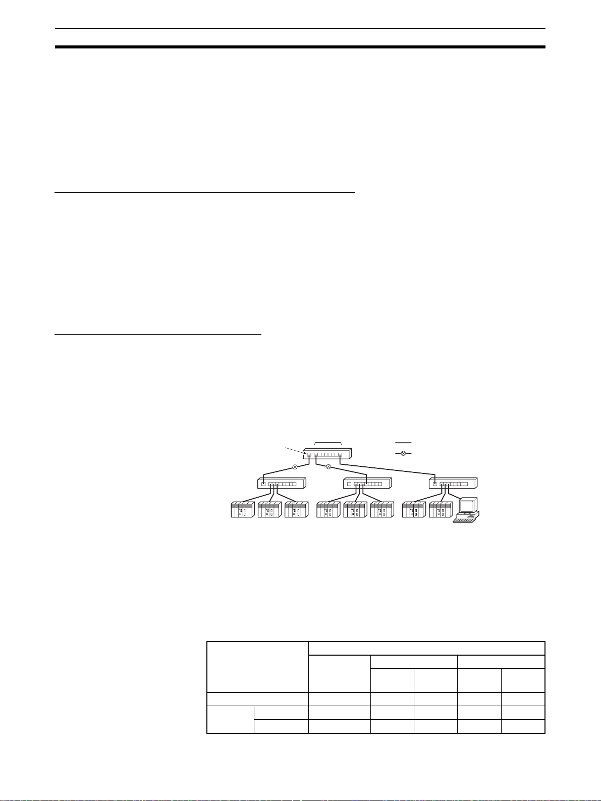
Network Installation Section 3-4
• Press the cable connector in firmly until it locks into place at both the
switching hub and the EtherNet/IP Unit.
• Do not lay the twisted-pair cab le together with high-voltage lines.
• Do not lay the twisted-pair cab le near devices that generate noise.
• Do not lay the twisted-pair cable in locations subject to high temperatures
or high humidity.
• Do not lay the twisted-pair cable in locations subject to excessive dirt and
dust or to oil mist or other contaminants.
Switching Hub Installation Environment Precautions
• Do not ground the switching hub in the same location as a drive-system
component such as an inve rter.
• Always use a dedicated power supply for the switching hub’s power supply. Do not use the same power supply used for other equipment, such as
an I/O power supply, motor power supply, or control power supply.
• Before installation, check the switching hub’s environment-resistance
specifications, and use a switching hub appropriate for the ambient conditions. Contact the switching hub manufacturer for details on switching
hub’s environment-resistance specifications.
Switching Hub Connection Methods
Connect two hubs to each other as follows: Connect an MDI port to an MDI-X
port with a straight cable; connect two MDI ports with a cross cable; and
connect two MDI-X ports with a cross cable.
Note It is very difficult to distinguish cross cables and straight cables by appear-
ance. Incorrect cables will cause communications to fail. We recommend
using cascade connections with straight cables whenever possible.
MDI-X port
(cross)
MDI ports
Switching
Hub
Switching
Hub
Straight cable
Cross cable
Switching
Hub
Switching
Hub
Some switching hubs can automatically distinguish between MDI and MDI-X.
When this kind of switching hub is being used, straight cable can be used
between switching hubs.
Note Adjust the link settings of the EtherNet/IP Unit or built-in EtherNet/IP por t to
match the communications settings of the conne cte d switching hub. If the settings do not match, the link will become unstable and prevent normal communications. The following table shows the allowed settings for each switching
hub communications mode.
Switching hub setting EtherNet/IP Unit setting
Auto-
negotiation
Auto-negotiation Best --- OK --- OK
10 Mbps
(fixed)
Full duplex --- OK --- --- --Half duplex OK --- OK --- ---
10 Mbps (fixed) 100 Mbps (fixed)
Full
duplex
Half
duplex
Full
duplex
Half
duplex
42
Page 69

Network Installation Section 3-4
b
t
g
Switching hub setting EtherNet/IP Unit setting
100 Mbps
(fixed)
Auto-
negotiation
Full duplex --- --- --- Best --Half duplex OK --- --- --- OK
10 Mbps (fixed) 100 Mbps (fixed)
Full
duplex
Half
duplex
Full
duplex
Half
duplex
Note Best = Recommended; OK = Allowed; --- = Not allowed.
3-4-4 Using Contact Outputs (Common to All Units)
When an EtherNet/IP Unit or built- in Ether Net/IP po rt and Contact Output Unit
are mounted in the same Rack or connected to the same PLC, communications errors may occur due to noise generated by the contact outputs. Use
one or more of the following measures when installing Contact Output Units
and EtherNet/IP Units on the same Rack.
Mounting Location
Mount (or connect) any Contact Output Units as far away from the EtherNet/IP
Unit or built-in EtherNet/IP port as possible.
Cable Location
Contact Output Unit
Contact outputs
EtherNet/IP Unit
To switching hu
Separate the transceiver cable or twisted-pair cable connecting the EtherNet/
IP Unit as far from the wiring to the Contact Output Units as possible. The
coaxial cable must also be placed as far away from the Contact Output Units
and their wiring as possible.
Contact outputs
Contact Output Unit
To switchin
EtherNet/IP Uni
hub
43
Page 70
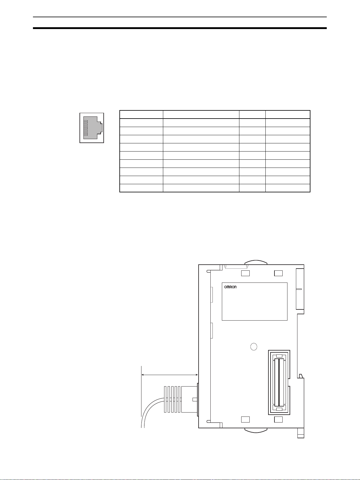
Connecting to the Network Section 3-5
3-5 Connecting to the Network
3-5-1 Ethernet Connectors
The following standards and specifications apply to the connectors for the
Ethernet twisted-pair cable.
• Electrical specifications:Conforming to IEEE802.3 standards.
• Connector structure: RJ45 8-pin Modular Connector
(conforming to ISO 8877)
Connector pin Signal name Abbr. Signal direction
1 Transmission data + TD+ Output
2 Transmission data – TD– Output
3 Reception data + RD+ Input
4 Not used. --- --5 Not used. --- --6 Reception data – RD– Input
7 Not used. --- --8 Not used. --- --Hood Frame ground FG ---
3-5-2 Connecting the Cable
!Caution Turn OFF the PLC’s power supply before connecting or disconnecting twisted-
pair cable.
!Caution Allow enough space for the bending radius of the twisted-pair cable as shown
in below.
35 mm
44
Page 71

Connecting to the Network Section 3-5
1,2,3... 1. Lay the twisted-pair cable.
2. Connect the cable to the switching hub. Be sure to press in the cable until
it locks into place.
3. Connect the twisted-pair cable to the connector on the EtherNet/IP Unit.
Be sure to press the connectors (both the s witching hub side and Ethernet
side) until they lock into place.
Example: CS1W-EIP21
RJ45 Modular Connector
EtherNet/IP Unit
45
Page 72

Creating I/O Tables Section 3-6
3-6 Creating I/O Tables
3-6-1 I/O Table Overview
I/O tables are used to identif y Units mo unted t o the PLC, and to allocate I/O to
them. With CS-series and CJ-series PLCs, whenever there is a change to the
Unit configuration it is necessary to create I/O tables and register the mounted
Units in the CPU Unit.
The I/O tables can be created in the following ways.
• Using the CX-Programmer offline.
• Using the CX-Programmer online to create the I/O table based on the
Units mounted to the PLC.
• Using the Programming Console to create the I/O table based on the
Units mounted to the PLC.
• Using the CPU Unit's automatic I/O allocation at startup. (This method is
available for the CJ Series only.)
3-6-2 Connecting Programming Devices to the PLC
To create the I/O tables, connect a Programming Device (such as a CX-Programmer or Programming Console) to the PLC.
Applicable Programming Devices
The following Programming Devices can be used with CS/CJ-series PLCs.
Programming Console
Model number Key Sheet (required) Recommended cable (required)
C200H-PRO27-E CS1W-KS001-E CS1W-CN224 (cable length: 2.0 m)
CQM1-PRO01-E CS1W-CN114 (cable length: 0.1 m)
Note A Programming Console cannot be used with the CJ2H-CPU@@(-EIP)
and CJ2M-CPU3@ CPU Units. Use the CX-Programmer.
CX-Programmer
For infor mation on how to connect and operate the CX-Programmer, refer to
the CX-Programmer Operation Manual (Cat. No. W446).
Connecting a Programming Console
To connect a Programming Console, attach a CS/CJ-ser ies Key Sheet and
then connect the Console to the CPU Unit’s peripheral port. (It cannot be connected to the RS-232C port.)
3-6-3 Procedure for Creating I/O Tables
Programming Console
This section provides the procedure for creating the I/O tables using a Programming Console. For details on using the Programming Console, refer to
the Programming Console’s operation manual.
CS1W-CN624 (cable length: 6.0 m)
46
Note (1) With the CJ Series, it is necessary to create I/O tab les only when the user
is allocating I/O manually. With the CS Series, it is always necessary to
create I/O tables.
Page 73

Creating I/O Tables Section 3-6
(2) With the CJ2H-CPU@@-EIP and CJ2M-CPU3@ CPU Units, the built-in
EtherNet/IP port is set in the I/O tables by de fault and cannot be change d.
It is not necessary to register it in the I/O tables.
Use the following procedure to create the I/O tables.
Initial screen
CH
SHIFT
*DM
000000 I/O TBL ?
CHG
000000 I/O TBL
WRIT ????
WRITE
Password
000000CPU BU ST?
0:CLR 1:KEEP
000000 I/O TBL
WRIT OK
CX-Programmer (Version 8.0 or Higher)
This section describes how to register an EtherNet/IP Unit or built-in EtherNet/
IP port in the I/O tables using the CX-Programmer (version 8.0 or higher).
Refer to the CX-Programmer Oper ation Man ual ( Cat. No. W446) for details on
the operating procedures.
This section describes how to register the CJ1W-EIP21 in the I/O tables by
creating the I/O tables on a computer with the CX-Programmer. In this
example, the computer is connected to the PLC using a serial cable. The
CJ1W-EIP21 is connected to a CJ1H-CPU67 CPU Unit.
1,2,3... 1. Start the CX-Programmer, and then select PLC
Connection from the menus.
or
(Save or clear the CPU Bus Unit System Setup.)
−
Auto On lin e − Direct
47
Page 74

Creating I/O Tables Section 3-6
2. The Direct Online Dialog Box will be displayed. Select a serial connection,
select the name of the applicable computer serial port, and then press the
Connect Button.
3. If the connection process is successful, the system will be connected online. Here, check the operating mode of the PLC. If the operating mode is
−
not PROGRAM mode, change the mode by selecting PLC
−
Mode
4. Double-click IO Table and Unit Setup Icon in the project workspace in the
CX-Programmer. The PLC IO Table Window will be displayed. Select Op-
tions
Program from the menus.
−
Create from the menus.
Operating
48
Page 75

Creating I/O Tables Section 3-6
5. The EtherNet/IP Unit will be displayed at the position it is mounted in the
PLC.
−
Note If it is not displayed, select Options
menus.
T rans fer f r om PLC from the
Note Creating I/O tables is not r equire d if t he built-in EtherNet/IP port of a CJ2 CPU
Unit is used. It is registered as a bu ilt-in port/Inner Board with a mode l number
of CJ2B-EIP21 for the CJ2H and a model number of CJ2M-EIP21 for the
CJ2M. You cannot delete a built-in port from the I/O tables.
49
Page 76

Setting the Local IP Address Section 3-7
3-7 Setting the Local IP Address
This section describes the 3 ways to set the local I/O address of an EtherNet/
IP Unit or built-in EtherNet/IP port.
Method 1: Using the default IP address:
The default IP address is 192.168.250.Node_address.
(The node address is set with the rotary switche s on the front of
the EtherNet/IP Unit or, for the built-in EtherNet/IP port, on the
front of the CPU Unit.)
→ This method can be used to make a temporary or preliminary
connection to the Ethernet. In this case, leave the TCP/IP Configuration and the allocate d DM area IP address settings at t heir
default values (0.0.0.0).
Method 2: Setting an IP address in the CPU Unit’s allocated DM area:
→ If y ou want to set a particular local IP address and store that set-
ting in the CPU Unit, set it in the EtherNet/IP Unit’s allocated DM
area. The IP address can be set from the CX-Progr ammer , Programming Console, or ladder program.
Method 3: Setting the TCP/IP Configuration from the CX-Pr o grammer:
→ If y ou want to set a particular local IP address and store that set-
ting in the EtherNet/IP Unit, set the IP address from the CX-Programmer.
When FINS communications are being used, it is necessary to show the correspondence between the IP addresses and FINS node addresses. Refer to
SECTION 5 Determining IP Addresses for an explanation of IP addr esses as
well as the correspondence between F INS node addresses a nd IP addresses .
The three setting methods are described in the following paragraphs.
Method 1:
When the EtherNet/IP Unit or built-in EtherNet/IP por t is just mounted in the
PLC and the I/O table is created, the EtherNet/IP Unit or built-in EtherNet/IP
port will operate with its default IP address. This default address is enabled
when the local IP address in the allocated DM area and the TCP/IP Configuration are both set to their defaults (0.0.0.0).
The default IP address is 192.168.250.Node_address, where Node_address
is the node address set with the rotary switches on the front of th e EtherNet/IP
Unit. This address is also used as the FINS node address.
The following table s hows the various settings in the Unit Setup when the IP
address and TCP/IP Configuration are all set to their default values.
IP address 192.168.250.Node_address
Subnet mask 255.255.255.0 (class C mask)
Default gateway None (IP routing disabled)
Preferred DNS server None
Alternate DNS server None
Host name None
Domain name None
Baud rate Auto-detect
Using the Default IP Address (192.168.250.Node_address)
Setting Operating status
50
Page 77

Setting the Local IP Address Section 3-7
Method 2: Setting the Address in the CPU Bus Unit's Allocated DM A rea
With this method, an IP address is not set in the TCP/IP Configuration (left at
its default setting), and an IP address is set in the allocated DM Area words
(the IP Address Display/Setting Area in words m+98 and m+99).
The IP address can be written in the two IP Address Display/Setting Area
words using the CX-Programmer or the Programming Console. To enable the
new IP Address setting, the EtherNet/IP Unit or built-in EtherNet/IP port must
be restarted or the PLC’s power must be turned OFF and then ON again.
Beginning word m = D30000 + (100 x unit number)
1514131211109876543210
m+98 (1) (2) (3) (4)
m+99 (5) (6) (7) (8)
IP Address: (1)(2).(3)(4).(5)(6).(7)(8) (Hex)
The following table shows the various Unit Setup when only the IP Address
Display/Setting Area is set, and the other TCP/IP Configuration settings are
left at their default values.
Setting Operating status
IP address IP address set in words m+98 and m+99 (IP Address Dis-
play/Setting Area) of the DM Area words allocated to the
EtherNet/IP Unit as a CPU Bus Unit
Subnet mask Determined by class of the IP address
Default gateway None (IP routing disabled)
Preferred DNS server None
Alternate DNS server None
Host name None
Domain name None
Baud rate Auto-detect
Method 3: Setting the TCP/IP Configuration from the Network
Configurator
This method can be used to set IP addresses from the CX-Programmer.
For details, refer to 3-8 TCP/IP and Link Settings.
If the IP address is set in the TCP/IP Tab Page, that IP address setting will be
displayed in the IP Address Display/Setting Area (words m+98 and m+99) in
the DM Area words allocated to the Unit/port.
51
Page 78

TCP/IP and Link Settings Section 3-8
3-8 TCP/IP and Link Settings
This section describes the TCP/IP-related settings, such as the local IP
address and subnet mask for th e EtherNet/IP Unit or built-in EtherNet/IP port.
Use the CX-Programmer to make these settings. The settings are stored in
non-volatile memory in the Unit.
Note Unlike the Ethernet Units, the TCP/IP settings of the EtherNet/IP Unit and
built-in EtherNet/IP port are not stored in the CPU Unit’s CPU Bus Unit System Setup Area.
3-8-1 Setting Procedure with the CX-Programmer
1,2,3... 1. When the EtherNet/IP Unit is registered in the I/O tables of the CX-Pro-
grammer, the EtherNet/IP Unit and built-in EtherNet/IP port will be displayed in the I/O tables. Refer to 3-6 Creating I/O Tables for details.
2. Right-click the EtherNet/IP Unit or built-in EtherNet/IP port in the I/O table
and select Edit - Unit Setup from the menus. The Edit P ar ameters Dialog
Box will be displayed.
3. Make the necessary settings on the TCP/IP Tab Page of the Edit Parameters Dialog Box. (The IP address is set here.)
52
Page 79

TCP/IP and Link Settings Section 3-8
4. Place the CX-Programmer online with the PLC and tr ansf er the setting s to
the EtherNet/IP Unit or built-in EtherNet/IP port .
5. After transferring the settings, a message will ask if you w ant to restart the
EtherNet/IP Unit or built-in EtherNet/IP port. The Unit/port must be restarted to enable the settings.
6. Check the 7-segment display for the EtherNet/IP Unit or built-in EtherNet/
IP port.
7. If the 7-segment display is tested again after it goes OFF, and finally
displays the IP address, it indicates that the EtherNet/IP Unit has
recognized the new TCP/IP Configuration settings (the IP address in this
case).
Note (1) The EtherNet/IP Unit or bu ilt-in EtherNet/IP port must restart in order to
enable the parameter settings that are transferred to it. V erify that restarting the Unit/port will not cause any problems in the system before restarting it.
(2) If the target node address (IP address) is not set correctly, invalid device
parameters may be set in the wrong PLC, so check the connected PLC
before downloading parameters.
Settings on the TCP/IP Tab Page
Settings for the following items are provided on the TCP/IP Tab Page of the
Edit Parameters Dialog Box in the CX-Programmer.
• IP address
• Subnet mask
• Default gateway
• Broadcasting
• Preferred DNS server
• Alternate DNS server
• Domain name
• IP router table
53
Page 80

TCP/IP and Link Settings Section 3-8
IP Address
Sets the local IP address of the EtherNet/IP Unit or built-in EtherNet/IP port.
Set the local IP address on the TCP/IP Tab Page when not setting the IP
address in the CPU Unit’s allocated DM Area or using the default IP address
(default IP address = 192.168.250.Node_address).
When the IP address is set on the TCP/IP Tab Page, it will be stored as the IP
address in the DM Area words allocated to the Unit/port as a CPU Bus Unit.
Subnet Mask
For the subnet mask, all bits corresponding to the bits in the IP address used
as the network ID are set to 1, and the bits corresponding to the host number
are set to 0. The EtherNet/IP Unit or built-in EtherNet/IP por t supports CIDR
(Classless Inter-Domain Routing). The subnet mask ca n be set to 192.0. 0.0 to
255.255.255.252. (CIDR is supported by unit version 2.0 or later.)
If no subnet mask is set, or if an illegal value is set, the following v alues will be
used depending on the IP address class.
In normal applications, we recommend setting the subnet mask defined for
the class.
Class Subnet mask
Class A 255.0.0.0
Class B 255.255.0.0
Class C 255.255.255.0
Default Gateway
Broadcasting
With the default setting (0.0.0.0), a subnet mask corresponding to the IP
address class is used.
The following table shows the various parameters in the Unit Setup when only
the IP address and subnet mask are set and other settings are left at their
default values.
Setting Operating status
Default gateway None (IP routing disabled)
Preferred DNS server None
Alternate DNS server None
Host name None
Domain name None
Broadcasting 4.3 BSD specifications
IP router table None
Sets the default gateway’s IP address.
This setting is not required when the default gateway is not being used.
Sets the IP address specification method for broadcasting with FINS/UDP.
• All 1’s (4.3BSD): Broadcasting is performed with the host ID set to all 1’s.
• All 0’s (4.2BSD): Broadcasting is performed with the host ID set to all 0’s.
Normally, use the default setting of all 1’s (4.3BSD).
Preferred DNS Server and Alternate DNS Server
When accessing another node from the EtherNet/IP Unit or built-in EtherNet/
IP port using the host name, the DNS server searches for the other node’s IP
address from the other node’s host name to the DNS server. These settings
register the IP addresses of the preferred and alternate DNS servers that will
perform the search. At this time, th e Ether Net/I P Unit is not equipp ed wit h any
54
Page 81

TCP/IP and Link Settings Section 3-8
functions that require a DNS server, so these settings are not used. (The
functionality required to use a DNS server is not provided on EtherNet/IP
Units with unit version 1.0. The DNS se rver cannot be used with these Units.)
Domain Name
Sets the domain name of the domain to which the EtherNet/IP Unit or built-in
EtherNet/IP port belongs. The EtherNet/IP Unit or built-in EtherNet/IP port
does not use a domain name in actual communications .
IP Router Table
Set the IP router table to route EtherNet/ IP comm unicatio ns for specific nodes
through an IP router other than the default gateway.
Settings on the Ethernet Tab Page
The following settings are provided on the Ethernet Tab Page of the Unit
Setup for the EtherNet/IP Unit or built-in EtherNet/IP port.
• Link settings (baud rate and half/full duplex)
Link Setting
Sets the communications baud rate.
Setting Meaning
Auto (default) The baud rate with the switching hub is detected automat-
10 Mbps, Half Duplex Operates in 10Base-T, half duplex.
10 Mbps, Full Duplex Operates in 10Base-T, full duplex.
100 Mbps, Half Duplex Operates in 100Base-TX, half duplex.
100 Mbps, Full Duplex Operates in 100Base-TX, full duplex.
ically. If possible, the Unit operates in 100Base-T (full
duplex).
Note Adjust the EtherNet/IP Unit’s link settings to match the communications set -
tings of the connected switching hub. If the settings do not match, the link will
become unstable and prevent normal communications. The following table
shows the allowed settings for each switching hub communications mode.
Switching hub setting EtherNet/IP Unit setting
Auto-
negotiation
Auto-negotiation Best --- OK --- OK
10 Mbps
(fixed)
100 Mbps
(fixed)
Full duplex --- OK --- --- --Half duplex OK --- OK --- --Full duplex --- --- --- Best --Half duplex OK --- --- --- OK
10 Mbps (fixed) 100 Mbps (fixed)
Full
duplex
Half
duplex
Note Best = Recommended; OK = Allowed; --- = Not allowed.
3-8-2 Making TCP/IP Settings with the Network Configurator
Use the Network Configurator to change IP address settings for any device
other than a CS/CJ-series EtherNet/IP Unit or built-in por t. You can also use
the Network Configurator to change IP address settings for a CS/CJ-series
EtherNet/IP Unit or built-in port.
1,2,3... 1. Connect the Network Configurator online.
Refer to 6-2-9 Connecting the Network Configurator to the Network fo r
details on connecting the Network Configurator to the EtherNet/IP Unit.
Full
duplex
Half
duplex
55
Page 82

TCP/IP and Link Settings Section 3-8
2. Select Tools - Setup TCP/IP Configuration to display the follo wing Setup
TCP/IP Configuration Dialog Bo x, and set t he TCP/IP Configur ation f or the
target device. In the following example, the settings are all at their default
values.
3. Enter the IP address to set and press the Get fr om the Device Button. The
present setting will be obtained. Change the IP address in the New Con-
figuration Box if required.
4. Press the Set to the Device Button. The IP address will be transferred to
the device. The applicable device is the device specified in the Ta rget I P
Address Box. The de vice must be r eset to enab le the tr ansf erred sett ing. If
the device is not reset when t he new IP address is tr ansferred, clic k the Re-
set the Device Button.
When the EtherNet/IP Unit is reset, the IP address will be displayed once
in flowing text on the 7-segment display on the front of the Unit.
56
Note (1) The transfer function for IP address settings is defined by ODVA specifi-
cations. Target devices that do not support these specifications cannot be
set. When setting the IP address of the target device with the Network
Page 83

Tag Data Link Parameters Section 3-9
Configurator, connect the devices one at a time, and download the TCP/
IP Configuration’s IP address parameters. If TCP/IP parameters are set
for the EtherNet/IP Unit or b uilt-in EtherNet/IP port from the Network Configurator, the EtherNet/IP Unit may automatically be reset and restar ted.
Before setting the TCP/IP parameters, make sure that no system problems will occur when the Unit is restarted. If the Unit does not restart automatically, click the Reset the Device Button.
(2) If the target node address (IP address) is not set correctly, invalid device
parameters may be set in the wrong PLC, so check the connected PLC
before downloading parameters.
TCP/IP Parameters
The following TCP/IP parameters can be set from the Network Configurator.
• IP address
• Subnet mask
• Default gateway
• Preferred DNS server
• Alternate DNS server
• Domain name
• Link parameters (baud rate and full/half duplex)
3-9 Tag Data Link Parameters
Set the following parameters when using tag data links with an EtherNet/IP
Unit or built-in EtherNet/IP port. The parameter settings are saved in flash
memory in the EtherNet/IP Unit or CPU Unit. (Se e note.)
Note The CPU Bus Unit Setup Area is not used for tag data link settings for an
EtherNet/IP Unit or built-in EtherNet/IP por t. This point is different from the
operation of Ethernet Units.
Refer to SECTION 6 Tag Data Link Functions for details.
3-9-1 Network Configurator Setting Procedure
The methods for setting tag data links using the Networ k Configurato r can be
roughly divided into the following two.
1. Using the EtherNet/IP Datalink Tool in the Network Configurator to Set the P arameters
With this method, there is no flexibility in the settings, but you can easily set
the data link parameters using only memory addresses, and the settings will
conform to Controller Link data link parameters.
2. Using the Tag Data Link Setting Function in the Network Configurator to Set the Parameters
With this method, you can set th e connect ions that comprise the tag data links
for each EtherNet/IP node. Tag data links can be set with a high degree of
flexibility using both memory addresses and network variables. Refer to SEC-
TION 6 Tag Data Link Functions for details on how to perform these settings.
This section presents a setting example using the EtherNet/IP Datalink Tool.
Using the EtherNet/IP Datalink T ool
The method that is described here is used to set memory addresses in tables
to specify data links between EtherNet/IP Units or built-in EtherNet/IP por ts
on CS/CJ-series PLCs.
57
Page 84

Tag Data Link Parameters Section 3-9
The following method can be used to easily set the data links shown in the following figure using a wizard in the EtherNet/IP Datalink Tool.
Area 1
Area 2
Node #1: CJ1H-CPU67H
(IP address: 192.168.250.1)
W0
50 words
W50
50 words
W100
50 words
D50
100 words
D150
100 words
D250
100 words
#1
#2
#3
#1
#2
#3
Node #2: CJ1H-CPU67H
(IP address: 192.168.250.2)
EtherNet/IP
W0
#1
#2
#3
D50 D50
#1
#2
#3
Node #3: CJ1H-CPU67H
(IP address: 192.168.250.3)
W0
#1
#2
#3
#1
#2
#3
1,2,3... 1. Start the Network Configurator, select the applicable EtherNet/IP Unit in
the Tree View on the left, and then paste it into the Device Configuration
Pane on the right.
Note If an EtherNet/IP system has already be en installed, you can create a sim ilar
device configuration by connecting to the EtherNet/IP network and selecting
−
Network
Upload from the menus.
Refer to 6-2-9 Connecting the Network Configurator to the Network for infor-
mation on connecting.
58
2. Select Network
−
EtherNet/IP Datalink Tool.
EtherNet/IP Datalink Tool from the menus to start the
Page 85

Tag Data Link Parameters Section 3-9
3. Select Datalink − Wizard from the menus in the Datalink Tool when it has
started.
4. In the Datalink Wizard Dialog Box, enter 50 words starting from memory
address W000 for area 1 and 100 words starting from D00050 for area 2,
and then press the OK Button.
5. The data link settings will be automatically created in the window of the
−
EtherNet/IP Datalink Tool. Select File
saved in the Network Configurator.
Save to end. The settings will be
59
Page 86

Tag Data Link Parameters Section 3-9
6. In the Device Configuration Window of the Network Configurator, a
mark will be added to each EtherNet/IP Unit to show that data links have
been set.
60
7. Connect the Network Configurator to the EtherNet/IP network and select
−
Network
loaded to the EtherNet/IP Units, and the data links will operate.
Download from the menus. The data link settings will be do wn-
Page 87

Other Parameters Section 3-10
3-10 Other Parameters
In addition to the tag data link parameters, the EtherNet/IP Unit and built-in
EtherNet/IP port also have the following communications and operation
parameters.
• FINS/UDP
•FINS/TCP
•FTP
• Auto Adjust Time
• Status Area
•SNMP
•SNMP Trap
These parameters are set as Unit Setup from the CX-Programmer. The
parameter settings are saved in flash memory in the EtherNet/IP Un it or CPU
Unit. (See note.)
Note The CPU Bus Unit Setup Area is not used for tag data link settings for an
EtherNet/IP Unit or built-in EtherNet/IP por t. This point is different from the
operation of Ethernet Units.
Using FINS/UDP
T ab Page in Edit
Parameters Dialog Box
FINS/UDP FINS/UDP Port Specifies the local UDP port number to use in the FINS communi-
Conversion Selects one of the following methods to convert from the FINS
IP Address Table Sets the IP address table that defines the relationship between
Dynamic change the target IP addresses
Setting Function
cations service. The UDP uses the UDP port number to distinguish
the application layer (FINS communications service in this case).
• Default value (9,600)
• User-set value (1 to 65,535)
node address to an IP address (FINS/UDP only).
• Automatic generation (dynamic setting)
• Automatic generation (static setting)
• IP address table
• Combined method
FINS node addresses and IP addresses.
This table is effective only when FINS/UDP is being used and the
IP address conversion method is set to the IP address table.
Selects dynamic change of other FINS/UDP nodes’ IP addresses.
To disable dynamic changes, deselect this option by removing the
check mark.
When necessary, set the routing tables using the CX-Integrator.
61
Page 88

Other Parameters Section 3-10
Using FINS/TCP
T ab Page in Edit
Parameters Dialog Box
FINS/TCP FINS/TCP Port Specifies the local TCP port number to use in the FINS communi-
FINS/TCP Connection
Setup
Protection Setting Select this check box to refuse connection requests from any IP
Setting Function
cations service. The TCP uses the TCP port number to distinguish
the application layer (FINS communications service in this case).
• Default value (9,600)
• User-set value (1 to 65,535)
This is the network API used when TCP is used for the FINS com-
munications service. Up to 16 APIs can be used at a time, and they
are identified by connection numbers 1 to 16.
The EtherNet/IP Unit or built-in EtherNet/IP port can thus simultaneously execute the FINS communications service by TCP with up
to 16 remote nodes.
address not set as the target IP address when the server/client
setting is set to a server and the target IP address is set to any
value other than 0.0.0.0.
This check box can be selected to prevent inappropriate operations on the PLC for FINS commands from specific nodes.
When necessary, set the routing tables using the CX-Integrator.
Using FTP
T ab Page in Edit
Parameters Dialog Box
FTP Not Use FTP or
Use FTP
Login Sets the login name for FTP connections to the EtherNet/IP Unit
Password Sets the password for FTP connections to the EtherNet/IP Unit or
Port No. Sets the FTP port number of the EtherNet/IP Unit or built-in
Setting Function
Specifies whether to use FTP. FTP connections from external
devices will not be possible if Not Use FTP is specified.
or built-in EtherNet/IP port from external devices
built-in EtherNet/IP port from external devices.
EtherNet/IP port.
It is normally not necessary to change this setting.
Two ports are used with the FTP: a control port and a data transfer
port. Only the control port can be set. The data transfer port number will be one larger than the control port number.
62
Page 89

Other Parameters Section 3-10
Using the Automatic Time Adjustment
T ab Page in Edit
Parameters Dialog Box
Auto Adjust Time Not get the time informa-
tion from the SNTP
server or
Get the time information
from the SNTP server
Auto Adjust time Sets the time to access the SNTP server to automatically adjust
Server Specification Type Specifies whether to use an IP address or a domain name (i.e.,
IP Address Sets the IP address of the SNTP server to use for automatic time
Host Name Sets the host name of the SNTP server to use for automatic time
Port No. Sets the port number to use to connect to the SNTP server for
Retry Timer Sets the time to wait before retrying the connection when connect-
Adjust Time Sets the time to offset the clock in the CPU Unit when setting the
Setting Function
Specifies whether to set the clock in the CPU Unit to the time on
the SNTP server.
The time can be set only in CPU Units with an EtherNet/IP Unit or
a built-in EtherNet/IP port.
the CPU Unit clock.
When the specified time arrives, the SNTP server will be accessed
and the clock in the CPU Unit will be set to the time on the SNTP
server.
host name) to specify the SNTP server to use for automatic time
adjustment.
adjustment.
This IP address is valid only when the Server Specification Type is
set to an IP address.
adjustment.
This IP address is valid only when the Server Specification Type is
set to a host name.
automatic time adjustment. It is normally not necessary to change
this setting.
ing to the SNTP server fails.
It is normally not necessary to change this setting.
clock in the CPU Unit to the time obtained from the SNTP server.
To use the time from the SNTP server as is, enter 0 for the Adjust
Time.
Using the Status Area
T ab Page in Edit
Parameters Dialog Box
Status Area Layout Type Specifies whether to use the default setting or a custom setting for
Allocation Area Sets the first word in the status area when the Layout Type is set
Setting Function
the words allocated to the status area.
for a customer setting.
With CS1/CJ1 CPU Units, only an I/O memory address can be set.
With CJ2 or NE1S CPU Units, either an I/O memory address or a
symbol defined in the CPU Unit can be set.
63
Page 90

Other Parameters Section 3-10
Using SNMP
T ab Page in Edit
Parameters Dialog Box
SNMP Not use SNMP service or
Use SNMP service
SNMP Port Sets the port number to use when connecting from an SNMP man-
SNMP Contact Information
SNMP Location Information
Authentication Check 1/2 Specifies the SNMP managers that can access the PLC.
Setting Function
Specifies whether to use the SNMP.
If not using the SNMP service is specified, an SNMP manager will
not be able to connected from an external device.
ager.
It is normally not necessary to change this setting.
Specifies the contact information as text.
This information can be read from the SNMP manager.
Specifies the location information as text.
This information can be read from the SNMP manager.
To restrict access to only specific SNMP managers, specify the
SNMP managers using IP addresses or host names. Community
names can also be specified (e.g., public).
Ether one or two settings can be made.
Using SNMP Trap
T ab Page in Edit
Parameters Dialog Box
SNMP Trap Not use SNMP Trap ser-
vice or
Use SNMP Trap service
SNMP Trap Port Sets the port number to use to connect to the SNMP manager.
Trap 1/2 Sets the SNMP manager destinations for SNMP traps.
Setting Function
Specifies whether to use the SNMP trap.
If not using the SNMP trap service is specified, SNMP traps cannot
be sent to the SNMP manager.
It is normally not necessary to change this setting.
The SNMP managers can be specified using IP addresses or host
names. Community names can also be specified (e.g., public).
Either one or two trap destinations can be set.
64
Page 91
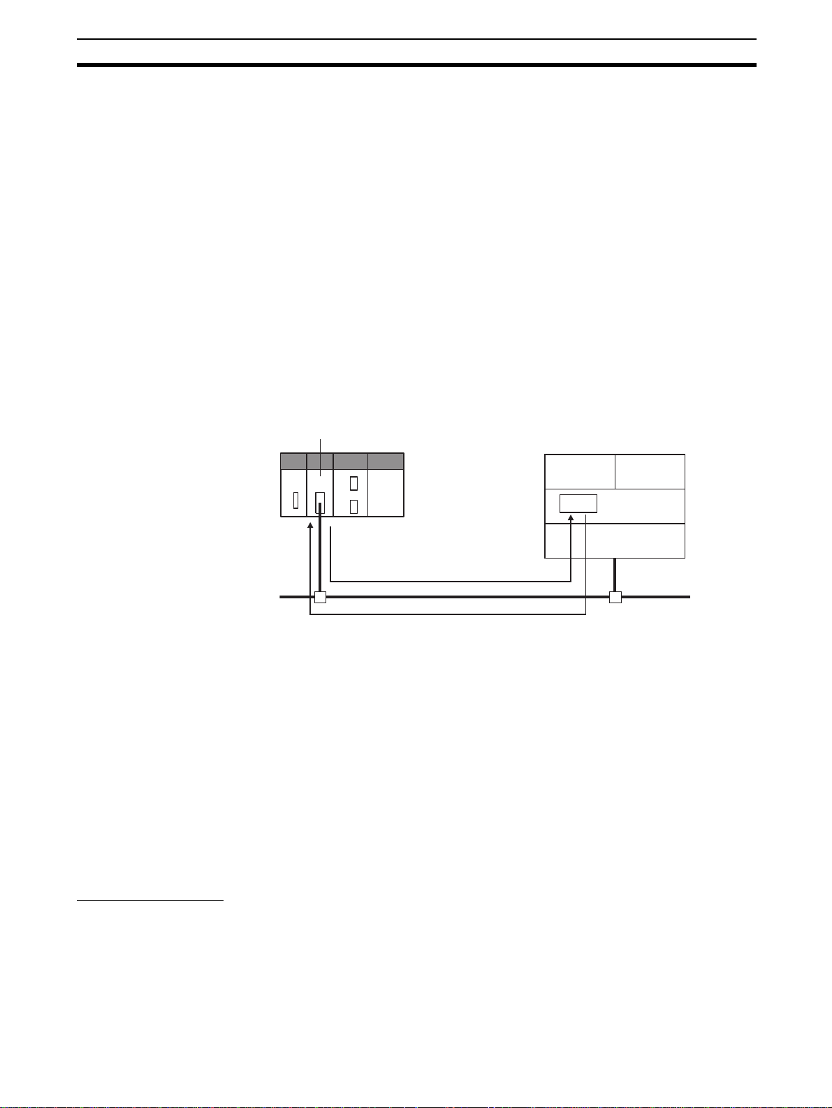
Communications Test Section 3-11
3-11 Communications Test
If the basic settings (in particular the IP address and subnet mask) have been
made correctly for the EtherNet/IP Unit or built-in EtherNet/IP port, then it
should be possible to communicate with nodes on the EtherNet/IP network.
This section describes how to use the PING command to test communications with the EtherNet/IP Unit or built-in EtherNet/IP port.
3-11-1 PING Command
The PING command sends an echo request packet to a remote node and
receives an echo response packet to confirm that the remote node is communicating correctly. The PING command uses the ICMP echo request and
responses. The echo response packet is automatically returned in the ICMP.
The PING command is normally used to check the connections of remote
nodes when configuring a network. The EtherNet/IP Unit or built-in EtherNet/
IP port supports both the ICMP echo request and reply functions.
If the remote node returns a normal response to the PING command, t hen the
nodes are physically connected correctly and Ethernet node settings are correct.
EtherNet/IP Unit
(host computer or EtherNet/IP Unit)
Remote Node
ICMP
Echo request
Echo response
IP
Ethernet
3-11-2 EtherNet/IP Unit or Built-in EtherNet/IP Port Operation
The EtherNet/IP Unit or built-in EtherNet/IP port automatically returns the
echo response packet in response to an echo request packet sent by another
node (host computer, or other EtherNet/IP Unit or built-in EtherNet/IP port).
An echo request packet can be sent to another node by issuing the FINS
command to execute the PING command from the PLC.
3-11-3 Host Computer Operation
The PING command can be executed from the host computer to send an
echo request packet to an EtherNet/IP Unit or built-in EtherNet/IP port . The
following example shows how to use the PING command in the host computer.
UDPTCP
Command Method
Input the following command at the host computer’s prompt ($):
$ ping IP_address(host_name)
The destination is specified by its IP addr ess or host name . If th e host name is
used, the host name must be defined in the /etc/hosts file.
Note The PING command is not supported by some host computers.
65
Page 92

Communications Test Section 3-11
Application Example
In this example, a PING command is sent to the node at IP address
130.25.36.8. The “$” in the example represents the host computer prompt.
Normal Execution
$ ping 130.25.36.8 ← Executes the PING command.
PING 130.25.36.8: 56 data bytes
64 bytes from 130.25.36.8: icmp_seq=0. time=0. ms
64 bytes from 130.25.36.8: icmp_seq=0. time=0. ms
: : : : :
64 bytes from 130.25.36.8: icmp_seq=0. time=0. ms
← Press the Ctrl+C Keys to cancel execution.
---- 130.25.36.8 PING Statistics ---9 packets transmitted, 9 packets received, 0% packets loss
round-trip (ms) min/avg/max = 0/1/16
$
Error Occurred
$ png 130.25.36.8 ← Executes the PING command.
PING 130.25.36.8: 56 data bytes
← Press the Ctrl+C Keys to cancel execution.
---- 130.25.36.8 PING Statistics ---9 packets transmitted, 9 packets received, 0% packets loss
$
Refer to the OS command reference manual for your computer for details on
using the PING command.
66
Page 93

SECTION 4
Memory Allocations
This section describes the words allocated in the CIO Area and the DM Area for EtherNet/IP Units or built-in EtherNet/IP
ports.
4-1 Overview of Memory Allocated to the EtherNet/IP Unit . . . . . . . . . . . . . . . . 68
4-2 CIO Area Allocations . . . . . . . . . . . . . . . . . . . . . . . . . . . . . . . . . . . . . . . . . . . 70
4-2-1 Overview of the Allocated CIO Area Words . . . . . . . . . . . . . . . . . . 70
4-2-2 Details of the Allocated CIO Area Words . . . . . . . . . . . . . . . . . . . . 71
4-3 DM Area Allocations . . . . . . . . . . . . . . . . . . . . . . . . . . . . . . . . . . . . . . . . . . . 83
4-3-1 Overview of the Allocated DM Area Words . . . . . . . . . . . . . . . . . . 83
4-3-2 Details of the Allocated DM Area Words. . . . . . . . . . . . . . . . . . . . . 83
4-4 User Settings Area . . . . . . . . . . . . . . . . . . . . . . . . . . . . . . . . . . . . . . . . . . . . . 85
4-4-1 Overview of the User Settings Area . . . . . . . . . . . . . . . . . . . . . . . . . 85
4-4-2 User Settings Area . . . . . . . . . . . . . . . . . . . . . . . . . . . . . . . . . . . . . . 85
4-5 Auxiliary Area Data . . . . . . . . . . . . . . . . . . . . . . . . . . . . . . . . . . . . . . . . . . . . 88
4-5-1 Read-only Bits/Words. . . . . . . . . . . . . . . . . . . . . . . . . . . . . . . . . . . . 88
4-5-2 Read/Write Bits (User Settings) . . . . . . . . . . . . . . . . . . . . . . . . . . . . 89
67
Page 94

Overview of Memory Allocated to the EtherNet/IP Unit Section 4-1
4-1 Overview of Memory Allocated to the EtherNet/IP Unit
The following CPU Unit words are allocated to the EtherNet/IP Unit or built-in
EtherNet/IP port.
• CPU Unit’s allocated CIO Area words
Contains software switch and status information.
• CPU Unit’s allocated DM Area words
Contains the IP Address Display/Setting Area
• CPU Unit’s user settings area
Contains status information. (This a rea can be used only when the allocated CIO Area words are set to user settings.)
Note The EtherNet/IP Unit or built-in EtherNet/IP p ort has the following
two data areas in its non-volatile memory. (Unlike the Ethernet
Units, settings are not stored in the CPU Unit’ s CPU Bus Unit System Setup Area.)
• Unit Setup: Settings such as the IP address and FINS/UDP settings. The Unit Setup is set from the CX-Programmer.
• Device parameter settings: Settings such as the tag data link setting parameters. The device parameter settings are made from the
Network Configurator.
68
Page 95

Overview of Memory Allocated to the EtherNet/IP Unit Section 4-1
CIO 1500
Unit number 0
Unit number 1
Unit number 15
Set in Network Configurator. →
Unit number 0
CIO 1501
CIO 1524
CIO 1525
CIO 1549
CIO 1875
CIO 1899
D30000
D30098
D30099
D30100
CPU Unit
● Allocated CIO Area words
(Allocated to the Unit as a CPU Bus Unit.)
● User Settings Area
● Allocated DM Area words
(Allocated to the Unit as a CPU Bus Unit.)
Flags and control bits
25 words
Target node PLC's operating
and error information, Unit
status, communications
status, registered/normal
25 words
25 words
64
100
target node, and FINS/TCP
connection status
words
Target node PLC's operating
and error information, and
registered/normal target
node
words
IP Address Display/Setting Area
EtherNet/IP Unit
Local memory
Local memory
Local memory
25 words
64
words
100 words
Unit number 1
Unit number 15
D30199
D31500
D31599
100
words
100
words
Network Configurator
Non-volatile memory in the EtherNet/IP
Unit
Unit settings
Settings such as the IP address of the
EtherNet/IP Unit and FINS/UDP settings.
Refer to 3-8 TCP/IP and Link Settings
and 3-10 Other Parameters for details.
Device parameter settings (tag data link
settings)
Refer to Section 6 Tag Data Links for
details.
69
Page 96

CIO Area Allocations Section 4-2
4-2 CIO Area Allocations
4-2-1 Overview of the Allocated CIO Area Words
The various kinds of data are stored in the allocated CIO Area words, which
are identified by the offset from the beginning word (n) allocated to each Unit.
There are two patterns for the layout of the allocated CIO Area words: the
default settings and user settings. The layout can be selected in the Status
Area settings in the Edit Parameters Dialog Box from the CX-Programmer.
To set a customer areas, select User defined for the Layout Type on the Status Area Tab Page .
The beginning word n is calculated by the following equation:
Beginning word n = CIO 1500 + (25 × unit number)
Default Settings
Offset
Bit
0
1
2
3
4
5
6
7
8
9
10
11
12
13
14
15
16
17
18
19
20
21
22
23
24
n
n+1
n+2
n+3
n+4
n+5
n+6
n+7
n+8
n+9
n+10
n+11
n+12
n+13
n+14
n+15
n+16
n+17
n+18
n+19
n+20
n+21
n+22
n+23
n+24
15 8 7 0
Unit control bits
(Reserved)
Target Node PLC Operating Information
(4 words only)
Target Node PLC Error Information
(4 words only)
Unit status 1
Unit status 2
Communications status 1
Communications status 2
Communications status 3
(Reserved)
Registered Target Node
(4 words only)
Normal Target Node
(4 words only)
FINS/TCP Connection Status
Data direction
CPU Unit → EtherNet/IP Unit
EtherNet/IP Unit → CPU Unit
EtherNet/IP Unit → CPU Unit
EtherNet/IP Unit → CPU Unit
EtherNet/IP Unit → CPU Unit
EtherNet/IP Unit → CPU Unit
EtherNet/IP Unit → CPU Unit
EtherNet/IP Unit → CPU Unit
EtherNet/IP Unit → CPU Unit
EtherNet/IP Unit → CPU Unit
70
Note The reserved words are regularly refreshed with all zeroes.
Page 97

CIO Area Allocations Section 4-2
User Settings
Offset
Bit
0
1
2
3
4
5
6
7
8
9
10
11
12
13
14
15
16
17
18
19
20
21
22
23
24
n
n+1
n+2
n+3
n+4
n+5
n+6
n+7
n+8
n+9
n+10
n+11
n+12
n+13
n+14
n+15
n+16
n+17
n+18
n+19
n+20
n+21
n+22
n+23
n+24
15 8 7 0
Unit control bits
(Reserved)
Unit status 1
Unit status 2
Communications status 1
Communications status 2
Communications status 3
(Reserved)
FINS/TCP Connection Status
Note The reserved words are regularly refreshed with all zeroes.
The functions of the allocated CIO Area words are descr ibed in the following
section.
Data direction
CPU Unit → EtherNet/IP Unit
EtherNet/IP Unit → CPU Unit
EtherNet/IP Unit → CPU Unit
EtherNet/IP Unit → CPU Unit
EtherNet/IP Unit → CPU Unit
EtherNet/IP Unit → CPU Unit
4-2-2 Details of the Allocated CIO Area Words
Unit Control Bits (CPU Unit to EtherNet/IP Unit) (n)
15 14 13 12 11 10 9 8 7 6 5 4 3 2 1 0
n
Bit Switch Status Manipulated
by
0 to 1 (Not used.) --- --- --2 Tag Data Link Start
Bit
ON User The tag data link starts when this bit
OFF Unit Turned OFF by Unit after the tag
Tag Data Link Start Bit
Tag Data Link Stop Bit
Adjust Clock Bit
Unit operation
is switched from OFF to ON.
data link starts operating.
71
Page 98

CIO Area Allocations Section 4-2
Tag Data Link Start Bit
(Bit 2)
Bit Switch Status Manipulated
3 (Not used.) --- --- --4 Tag Data Link Stop
Bit
5 Adjust Clock Bit ON User The clock time is automatically
6 to 15 (Not used.) --- --- ---
ON User The tag data link stops when this bit
OFF Unit Turned OFF by Unit after the tag
OFF Unit Turned OFF by Unit after the clock
by
is switched from OFF to ON.
data link stops operating.
adjusted when this bit is switched
from OFF to ON.
time has been adjusted.
Unit operation
Start the tag data link s by switching this bit from OFF to ON. If the tag data
links are already operating, the signal will be ignored. The tag data link starts
operating automatically after the tag data link parameter settings are downloaded from the Network Co nfigurator, the CPU Unit’s power is turned ON, or
the Unit is restarted.
If the tag data links have been stopped by turning the Tag Data Link Stop Bit
(n bit 04) from OFF to ON, the tag data links can be resta r ted by turning this
Tag Data Link Start Bit (n bit 02) from OFF to ON.
Once the tag data links start, the EtherNet/IP Unit automatically turns OFF the
Tag Data Link Start Bit. Do not force this bit ON or OFF until it is automat ically
turned OFF by the Unit.
Tag Data Link Stop Bit
(Bit 4)
Stop the tag data links by switching this bit from OFF to ON. Once the tag
data links have been stopped, they will remain stopped until the Unit is
restarted or the Tag Data Link Start Bi t is turned ON. (The tag data links will
also start operating automatically when the tag data link parameter sett ings
are downloaded from the Network Configurator.)
If the tag data links are already stopped, the signal will be ignored.
Message communications can be performed while the tag data links are
stopped.
Once the tag data links have stopped, the EtherNet/IP Unit automatically
turns OFF the T ag Data Link Stop Bit. Do not f orce this bit ON or OFF until it is
automatically turned OFF by the Unit.
Adjust Clock Bit (Bit 5) Automatically adjust the time o n the clock by switching this bit from OFF to
ON. The SNTP server used to adjust the time is set in the Unit Setup.
Once the clock time has been adjusted, the EtherNet/IP Unit automatically
turns OFF the Adjust Clock Bit. Do not force this bit ON or OFF until it is automatically turned OFF by the Unit.
Target Node PLC
Operating Information
(EtherNet/IP Unit to
CPU Unit) (n + 2 to n +
5)
These words show the operating status of the target node PLCs that are connected with the EtherNet/IP Unit as the originator. This status information is
enabled when the PLC status is included in the communications data in both
the originator and target node.
These words show the status of nodes 0 to 63 only. If it is necessary to show
the status of nodes higher than node 63, select “user settings” as the layout
pattern. For details, refer to 4-4 User Settings Area.
The flags are valid only when the corresponding Normal Target Node Flag is
ON. If the corresponding Nor mal Target Node Flag is O FF, the Target Node
PLC Operating Flag indicates the previous operating status.
72
Page 99

CIO Area Allocations Section 4-2
15 14 13 12 11 10 9 8 7 6 5 4 3 2 1 0
n+2
15 14 13 12 11 10 9 8 7 6 5 4 3 2 1 0
n+3
31 30 29 28 27 26 25 24 23 22 21 20 19 18 17 16
n+4
47 46 45 44 43 42 41 40 39 38 37 36 35 34 33 32
n+5
63 62 61 60 59 58 57 56 55 54 53 52 51 50 49 48
Target Node PLC
Error Information
(EtherNet/IP Unit to
CPU Unit) (n + 6 to n +
9)
Bit Name Status Manipulated
Unit operation
by
--- Target Node PLC Operating Flags
ON Unit The corresponding PLC
is operating. (The program is being executed.)
OFF Unit The PLC is not operating.
These words show the error status (logical OR of fatal and non-fatal errors) of
the target node PLCs that are connected with the EtherNet /IP Unit as the originator. This status information is enabled when the PLC status is included in
the communications data in both th e originator and target node.
These words show the error status of nodes 0 to 63 only. If it is necessar y to
show the error status of nodes higher than node 63, select “user settings” as
the layout pattern. For details, refer to 4-4 User Settings Area.
The flags are valid only when the corresponding Normal Target Node Flag is
ON. If the corresponding Nor mal Target Node Flag is O FF, the Target Node
PLC Error Flag indicates the previous error status.
15 14 13 12 11 10 9 8 7 6 5 4 3 2 1 0
n+6 15 14 13 12 11 10 9 8 7 6 5 4 3 2 1 0
n+7 31 30 29 28 27 26 25 24 23 22 21 20 19 18 17 16
n+8 47 46 45 44 43 42 41 40 39 38 37 36 35 34 33 32
n+9 63 62 61 60 59 58 57 56 55 54 53 52 51 50 49 48
Bit Name Status Manipulated
by
--- Target Node PLC Error
ON Unit A fatal or non-fatal error
Flags
OFF Unit No error occurred in the
Unit operation
occurred in the corresponding PLC.
PLC.
Unit Status 1
(EtherNet/IP Unit to
CPU Unit) (n + 10)
n+10
15 14 13 12 11 10 9 8 7 6 5 4 3 2 1 0
Unit Error Occurred
Network Error Occurred
Unit Memory Error
Communications Controller Error
IP Address Duplication Error
Link OFF Error
Status Area Layout Setting Error
73
Page 100

CIO Area Allocations Section 4-2
Bit Name Status Manipulated
0 Unit Error Occurred ON Unit Indicates that an error
OFF Unit Indicates that a Unit error
1Network Error
Occurred
2 to 3 (Not used) --- --- --4 Unit Memory Error ON Unit Indicates that an error
5 Communications
Controller Error
6 IP Address Duplica-
tion Error
7 to 8 (Not used) --- --- --9 Link OFF Error ON Unit There was an error estab-
ON Unit One or more network-
OFF Unit Indicates that a network
OFF Unit Indicates that a non-volatile
ON Unit Indicates that an error
OFF Unit Indicates that a communica-
ON Unit An ARP was sent with the
OFF Unit There was no ARP
OFF Unit A link was established nor-
by
Unit operation
occurred that is related to
EtherNet/IP Unit operation.
This flag is turned ON when
any bit in Unit Status 1 is
ON. (Bits 1 to 15 are logically ORed.)
did not occur. This flag is
turned OFF when the error
is cleared.
related errors occurred.
(The bits in Communications Status 1 and 3 are logically ORed.)
error did not occur. This flag
is turned OFF when the
error is cleared.
occurred in accessing the
Unit’s internal non-volatile
memory (device error).
memory error did not occur.
This flag is not cleared e ven
if it occurs one time. (Flag
remains ON.)
occurred in the communications controller.
tions controller error did not
occur. This flag remains ON
until the power supply is
turned OFF and ON again.
specified IP address, indicating that an IP address
duplication was detected.
An address duplication is
detected if there is an ARP
response. This flag remains
ON until the power supply is
turned OFF and ON again.
(The Ethernet interface will
stop.)
response.
lishing a link with the switching hub.
mally with the switching hub.
74
 Loading...