

Omron STC-SBE132POE, STC-SCE132POE, GigE Vision STC-SCS43POE, GigE Vision STC-SBS43POE, GigE Vision STC-SBS163POE Owner's Manual
...
GigE Vision
Aegis Electronic Group, Inc.
For more information please contact Aegis Electronic Group, Inc. *(888)687-6877 *aegis-g2@aegiselect.com *http://www.aegiselect.com
Color / Monochrome CMOS PoE Camera
STC-SBE132POE (1.3M / Monochrome)
STC-SCE132POE (1.3M / Color)
No.14S002-08
Product Specifications and User’s Guide
STC-SBE132POE / STC-SCE132POE
Product Specifications and User’s Guide
1/53

No.14S002-08
Aegis Electronic Group, Inc.
For more information please contact Aegis Electronic Group, Inc. *(888)687-6877 *aegis-g2@aegiselect.com *http://www.aegiselect.com
Table of Contents
1 Product Precautions ............................................................................................ 7
2 Warranty ................................................................................................................ 7
3 Introduction .......................................................................................................... 8
3.1 Features .................................................................................................................................... 8
3.2 Product Number Naming Method ........................................................................................... 8
4 Specifications ....................................................................................................... 9
4.1 Electronic Specifications ......................................................................................................... 9
4.2 Spectral Sensitivity Characteristics ..................................................................................... 10
4.2.1 STC-SCE132POE / STC-SBE132POE ............................................................................................. 10
4.2.2 IF Cut Filter (STC-SCE132POE) ...................................................................................................... 10
4.3 Mechanical Specifications ..................................................................................................... 11
4.4 Environmental Specifications ............................................................................................... 11
5 Connector Specifications .................................................................................. 12
5.1 RJ45 Connector ...................................................................................................................... 12
5.2 Power / IO Control Signal Connector ................................................................................... 13
5.2.1 Equivalent Circuit for the Input Pin of the I/O Connector ............................................................. 15
5.2.2 Typical Input Circuit ........................................................................................................................ 16
5.2.3 Typical Output Circuit ..................................................................................................................... 17
5.2.4 Input and Output Signal Timing (Hardware Trigger) ..................................................................... 18
5.2.5 Input and Output Signal Timing (Software Trigger) ...................................................................... 19
6 Dimensions ......................................................................................................... 20
6.1 STC-SBE132POE .................................................................................................................... 20
6.2 STC-SCE132POE .................................................................................................................... 20
7 Sensor information ............................................................................................ 21
7.1 Pixel Transferring Image ........................................................................................................ 21
STC-SBE132POE / STC-SCE132POE
Product Specifications and User’s Guide
2/53

No.14S002-08
Aegis Electronic Group, Inc.
For more information please contact Aegis Electronic Group, Inc. *(888)687-6877 *aegis-g2@aegiselect.com *http://www.aegiselect.com
8 Camera Operational Modes ............................................................................... 22
8.1 Normal Mode (TriggerMode=Off)........................................................................................... 22
8.2 Edge Preset Trigger Mode (ExposureMode=Timed) ............................................................ 22
8.2.1 Timing .............................................................................................................................................. 22
8.2.2 Exposure Timing with the Positive Polarity Trigger Signal .......................................................... 23
8.2.3 Exposure Timing with the Negative Polarity Trigger signal ......................................................... 23
8.3 CMOS Rest Type ..................................................................................................................... 24
9 Camera Functions .............................................................................................. 25
9.1 ROI (Region of Interest) ......................................................................................................... 25
9.1.1 ROI (1 region) .................................................................................................................................. 25
9.2 Pixel Format ............................................................................................................................ 27
9.3 Binning .................................................................................................................................... 27
9.4 Decimation .............................................................................................................................. 28
9.5 Image Flip................................................................................................................................ 29
9.6 Gain ......................................................................................................................................... 31
9.6.1 Analog gain ..................................................................................................................................... 31
9.6.2 Digital gain ...................................................................................................................................... 31
9.7 Black level ............................................................................................................................... 31
9.8 ALC (Auto Light Control) ....................................................................................................... 32
9.8.1 ALC control method........................................................................................................................ 33
9.8.2 AGC (Auto Gain Contorl) ................................................................................................................ 33
9.8.3 Auto shutter .................................................................................................................................... 34
9.8.4 ALC settings procedure ................................................................................................................. 34
9.9 White balance (Only available for the color cameras) ........................................................ 35
9.9.1 White balance control methods ..................................................................................................... 35
9.9.2 OFF .................................................................................................................................................. 36
9.9.3 Auto white balance ......................................................................................................................... 36
9.9.4 Push to set white balance .............................................................................................................. 36
9.9.5 Preset white balance1 to 3 ............................................................................................................. 37
9.9.6 White balance calculate area setting ............................................................................................. 38
9.10 Gamma correction ............................................................................................................... 39
9.10.1 Gamma table writing.................................................................................................................... 39
9.11 Save and load the camera setting data ............................................................................. 40
STC-SBE132POE / STC-SCE132POE
Product Specifications and User’s Guide
3/53

No.14S002-08
Aegis Electronic Group, Inc.
For more information please contact Aegis Electronic Group, Inc. *(888)687-6877 *aegis-g2@aegiselect.com *http://www.aegiselect.com
9.11.1 Saving the Camera Settings ........................................................................................................ 40
9.11.2 Loading Camera Settings ............................................................................................................ 41
9.11.3 Loading Camera Settings when the Camera Power is on ......................................................... 41
9.11.4 Camera Settings Initialization ..................................................................................................... 41
9.12 Trigger .................................................................................................................................. 42
9.12.1 Trigger Signal Processing Process ............................................................................................ 42
9.13 The camera settings (GenICam parameters) control with SDK ....................................... 43
9.13.1 Integer type parameter control ................................................................................................... 43
9.13.2 Float type parameter control ....................................................................................................... 43
9.13.3 Enumeration type parameter control ......................................................................................... 43
9.13.4 String type paramter control ....................................................................................................... 44
9.13.5 Boolean type parameter control ................................................................................................. 44
9.13.6 Command type paramter control ................................................................................................ 44
9.14 GenICam Command List ..................................................................................................... 45
9.14.1 DeviceControl .............................................................................................................................. 45
9.14.2 ImageFormatControl.................................................................................................................... 45
9.14.3 AcquisitionControl ...................................................................................................................... 46
9.14.4 DigitalIOControl ........................................................................................................................... 46
9.14.5 CounterAndTimerControl ............................................................................................................ 47
9.14.6 EventControl ................................................................................................................................ 47
9.14.7 AnalogControl .............................................................................................................................. 47
9.14.8 TransportLayerControl ................................................................................................................ 48
9.14.9 UserSetControl ............................................................................................................................ 49
9.14.10 IPEngine ....................................................................................................................................... 49
9.14.11 SpecialFeatures ........................................................................................................................... 50
10 Revision History ................................................................................................. 52
STC-SBE132POE / STC-SCE132POE
Product Specifications and User’s Guide
4/53
No.14S002-08
Aegis Electronic Group, Inc.
For more information please contact Aegis Electronic Group, Inc. *(888)687-6877 *aegis-g2@aegiselect.com *http://www.aegiselect.com
Precautions for safe use
Please read carefully this “Precautions for safe use” before use the camera. Then the camera uses correctly with
agreeing with below notes.
In this “Precautions for safe use”, notes divides into “Warning” and “Caution” to use the camera safety and prevent to
harm and damage.
This shows, assumption for possibility of serious accident leading death or
Warning
Caution
About Graphic
symbols
[Environment / condition]
serious injury if ignore this note and camera uses incorrectly.
This shows, assumption for possibility of bear the damage or physical
damage if ignore this note and camera uses incorrectly.
This symbol shows general prohibition.
This symbol shows completion or instruction.
Warning
Do not use flammable or explosiveness
atmospheres.
This will cause of personal injury or fire.
Caution
Use and store under specified environmental
conditions (Vibration, shock, temperature,
humidity) in the specifications for this camera.
This will cause of fire or damage the camera.
[Installation and cable wiring]
Warning
Do not use with out of power voltage range
that is specified in the specifications for this
camera.
This will cause of fire, electrification or
malfunction.
Do not use for “safety for human body” related
usage.
This camera is designed for use “do not harm
human body immediately” if by any chance the
camera has malfunction.
Do not wrong wiring.
This will cause of fire or malfunction.
STC-SBE132POE / STC-SCE132POE
Product Specifications and User’s Guide
5/53
Aegis Electronic Group, Inc.
For more information please contact Aegis Electronic Group, Inc. *(888)687-6877 *aegis-g2@aegiselect.com *http://www.aegiselect.com
Caution
The camera housing is not connecting to 0 V line
of camera inside circuit.
There is a risk of short circuit between camera
inside ciurcuit and frame ground through other
devices.
This will cause of malfunction.
It is necessary to wiring with turn off the camera.
This will cause of electrification or malfunction.
[Usage instruction]
No.14S002-08
It is necessary to wiring and mounting that is
specified in the specifications for this camera.
This will cause of fire or malfunction.
It is necessary to mounting the camera without
stress for the cable.
This will case of electrification or fire.
Warning
Do not touch the terminal and PCB board
While turn on the camera.
This will cause of electrification or accident
caused by malfunction.
Do not use without usage that is specified in
the specifications for this camera.
This will cause of personal injury or malfunction.
Caution
Do not push contamination into opening of
the camera.
This will cause of electrification or malfunction.
[Maintenance]
Caution
Do not disassemble or repair the camera.
This will cause of fire, electrification or
malfunction.
[Disposal]
Do not put combustibles near the camera.
This will cause of fire.
Do not push metals including screw driver into
radiation holes.
This will cause of electrification or malfunction.
Do not block the radiation holes.
This will cause of fire due to increase the
camera inside temperature.
It is turn off the camera when maintaining or
inspecting the camera.
This will cause of electrification.
Caution
It is necessary to dispose as industrial waste.
]
STC-SBE132POE / STC-SCE132POE
Product Specifications and User’s Guide
6/53

Aegis Electronic Group, Inc.
For more information please contact Aegis Electronic Group, Inc. *(888)687-6877 *aegis-g2@aegiselect.com *http://www.aegiselect.com
1 Product Precautions
Do not give shock to the camera.
Do not haul or damage the camera cable.
Do not wrap the camera with any material while using the camera. This will cause the internal camera
temperature to increase.
When the camera moving or using the place that temperature difference is extreme, countermeasure for dew
condensation (heat removal / cold removal) is necessary.
While the camera is not using, keep the lens cap on the camera to prevent dust or contamination from getting
in the sensor or filter and scratching or damaging it.
Do not keep the camera under the following conditions.
・ In wet, moist, high humidity or dusty place
・ Under direct sunlight
・ In extreme high or low temperature place
・ Near an object that releases a strong magnetic or electric filed
・ Place with strong vibrations
Apply the power that satisfies the specified in specifications for the camera.
The defective pixels may appear due to the sensor characteristics.
Use below recommend materials (or equivalent materials) to clean the surface of glass.
・ Air dust: Non Freon air duster (NAKABAYASHI Co., LTD.)
・ Alcohol: Propan-2-ol (SAN’EI KAKO Co., LTD.)
・ Non-woven: nikowipe clean room (NKB)
Use a soft cloth to clean the camera.
No.14S002-08
2 Warranty
■Warranty period
One year after delivery (However, the camera had malfunction with camera uses correctly)
In below case for a fee even within warranty period.
・The malfunction caused by incorrect usage, incorrect modify or repair.
・The malfunction caused by external shock including the camera dropping after delivery the camera.
・The malfunction caused by fire, earthquake, flood disaster, thunderbolt struck, other natural disaster or
wrong voltage.
■Warranty coverage
Exchange or repair the malfunction camera if the malfunction is occurred by our responsibility.
“Warranty” mean is warranty for the delivered camera itself. Please accept the induction damage by the
camera malfunction is not included.
STC-SBE132POE / STC-SCE132POE
Product Specifications and User’s Guide
7/53
Aegis Electronic Group, Inc.
For more information please contact Aegis Electronic Group, Inc. *(888)687-6877 *aegis-g2@aegiselect.com *http://www.aegiselect.com
3 Introduction
This document describes the specification of the following cameras:
STC-SBE132POE / STC-SCE132POE
3.1 Features
Support PoE (Power over Ethernet Support)
Maximum Frame Rate (Full Scanning): 61 fps @ 1.3M 8bits
CMOS (Global Shutter)
Defective Pixel Correction up to 64 points
8bits or 10bits output
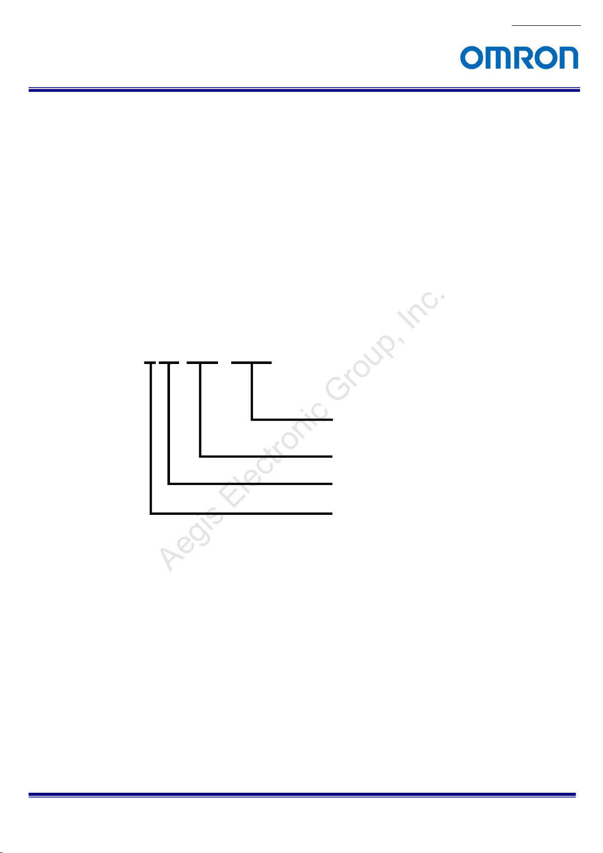
3.2 Product Number Naming Method
No.14S002-08
STC-SxE132POE
POE: PoE (Power over Ethernet GigE)
132: 1.3M, 1/1.8” sensor
Sensor Manufacture
E: e2V
B: Monochrome
C: Color
STC-SBE132POE / STC-SCE132POE
Product Specifications and User’s Guide
8/53
Aegis Electronic Group, Inc.
For more information please contact Aegis Electronic Group, Inc. *(888)687-6877 *aegis-g2@aegiselect.com *http://www.aegiselect.com
4 Specifications
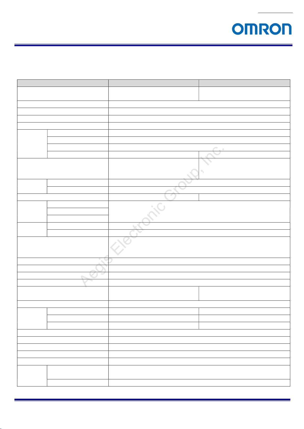
4.1 Electronic Specifications
Model Number STC-SBE132POE STC-SCE132POE
Image Sensor 1/1.8” 1.3M Progressive Monochrome CMOS
(e2V: EV76C560)
Shutter Type Global / Rolling Shutter
Active Picture Elements 1,280 (H) x 1,024 (V)
Cell Size 5.3 (H) x 5.3 (V) µm
Sync Method
Maximum
Frame Rate
(at Full
scanning)
Image Output Format
Noise Level 8bits output Less than 3 digits (Gain 0 dB)
10bits / 10bits Packed output Less than 12 digits (Gain 0 dB)
Minimum Scene Illumination 0.6 Lux at F1.2 (Gain Max) 50 Lux at F1.2 (Gain Max)
Exposure 8bits output
Time 10bits / 10bits Packed output
RGB8 Packed output
Gain Analog
ROI
Multi ROIs N/A
Gamma
Binning
Decimation
Flip Image Horizontal / Vertical / Horizontal and vertical /
Pixel Blemish Correction
Auto Image
Control
Operational Mode
Communication UART communication through Ethernet port
Protocol IEEE802.3 (1000BASE-T)
Communication GigE Vision 1.2, GenICam 1.4
I/O One opt-isolated inputs and two open collector outputs (+3.3V)
Power Input Voltage +10.8 to +26.4 Vdc (IO Connector)
8bits output
10bits output 31 fps
10bits Packed output 42 fps
RGB8 Packed output N/A 21 fps
Mono8 / Mono10 / Mono10Packed
Digital
Horizontal: 32 to 1,280 pixels / Vertical: 32 to 1,024 lines (Default: 1,280 x 1,024)
Adjustable steps for image size: 8 pixels in horizontal direction / 2 lines in vertical direction
Adjustable steps for offset: 8 pixels in horizontal direction / 2 lines in vertical direction
Auto Exposure Support Support
Auto Gain (AGC) Support Support
Auto White Balance N/A Support
Power Consumption 12V: Less than 3.1 W / PoE: Less than 2.8 W
External trigger (Hardware / Software) / Free run
61 fps
10 µseconds to 1,000 seconds (Default: 16,379 µseconds)
0 to 5.38 dB (Default: 0)
0 to 9.51 dB (Default: 0)
Gamma 1.0 or uploadable gamma table
Horizontal: 1/2, Vertical: 1/2 / Off
Horizontal: 1/2, Vertical 1/2 / Horizontal 1/4, Vertical: 1/4 / Off
Off
Up to 64 points (Default: ON)
Edge Preset Trigger / Free run
or Power Over Ethernet (IEEE802.3af compliance)
1/1.8” 1.3M Progressive Color CMOS
(e2V: EV76C560)
Mono8 / Mono10 / Mono10Packed /
BayerRG8 / BayerRG10 /
BayerRG10Packed / RGB8Packed
Horizontal / Off
No.14S002-08
Default: Bold
STC-SBE132POE / STC-SCE132POE
Product Specifications and User’s Guide
9/53
Aegis Electronic Group, Inc.
For more information please contact Aegis Electronic Group, Inc. *(888)687-6877 *aegis-g2@aegiselect.com *http://www.aegiselect.com
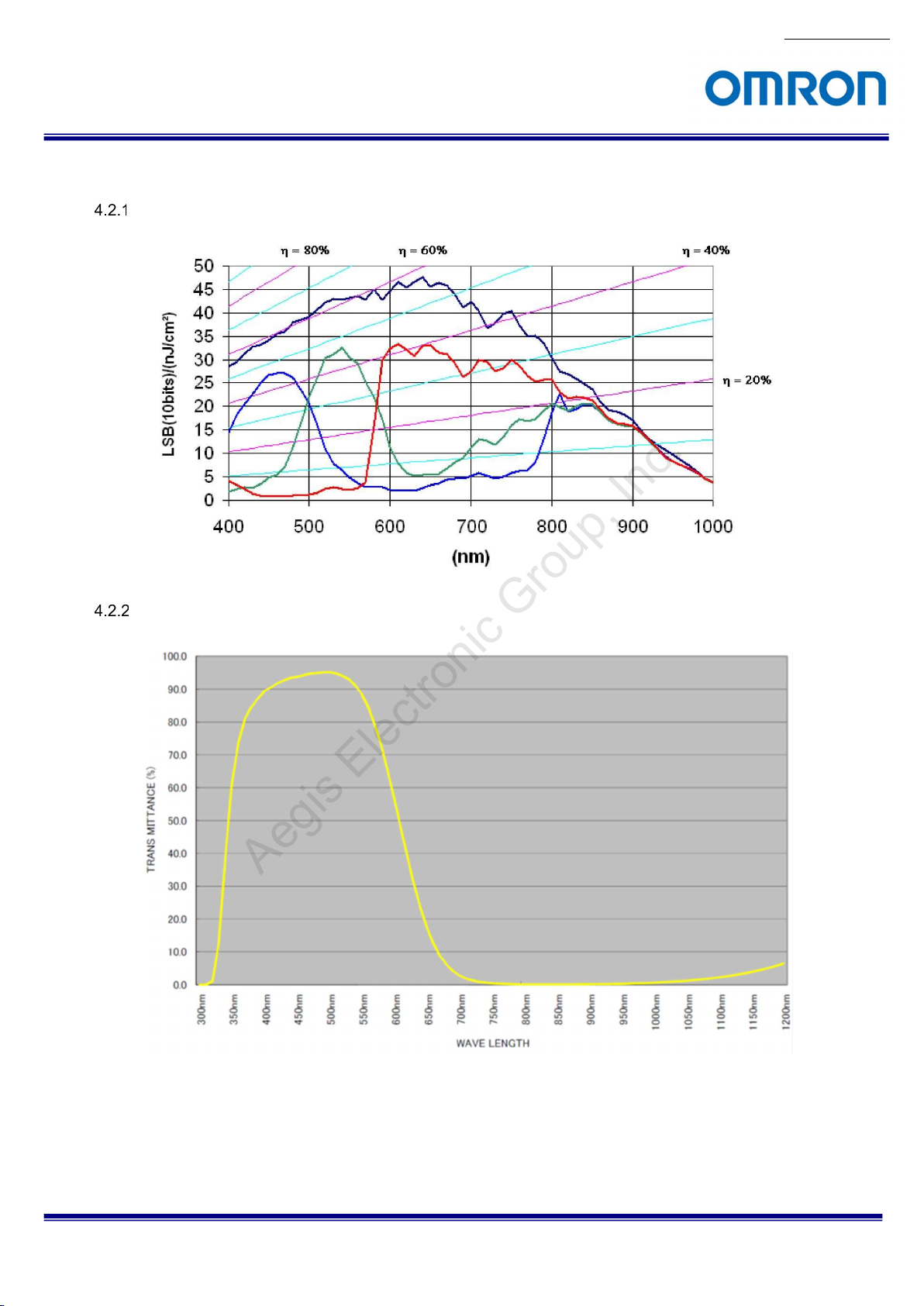
4.2 Spectral Sensitivity Characteristics
STC-SCE132POE / STC-SBE132POE
IF Cut Filter (STC-SCE132POE)
No.14S002-08
STC-SBE132POE / STC-SCE132POE
Product Specifications and User’s Guide
10/53
No.14S002-08
Aegis Electronic Group, Inc.
For more information please contact Aegis Electronic Group, Inc. *(888)687-6877 *aegis-g2@aegiselect.com *http://www.aegiselect.com
4.3 Mechanical Specifications
Model Number STC-SBE132POE STC-SCE132POE
Dimensions 35 (W) x 35 (H) x 53.5 (D) mm (*1) 35 (W) x 35 (H) x 54.3 (D) mm (*1)
Optical Filter No Optical Filter No IR Cut Filter
Optical Center Accuracy Positional accuracy in Horizontal and Vertical directions: +/- 0.3 mm
Rotational accuracy of Horizontal and Vertical: +/- 2.0 deg.
Material Aluminum Alloy
Lens Mount C, mount, CS mount
Connectors RJ45 connector
Power- I/O connector: HR10A-7R-6PB (Hirose) or equivalent
Camera Mount Screws Two 1/4” Tripod screw holes (One on top and bottom plate)
Eight M4 screws holes (Four on top and bottom plate)
Weight Color: Approximately 100 g, Mono: Approximately 98 g
(*1) Excluding connectors
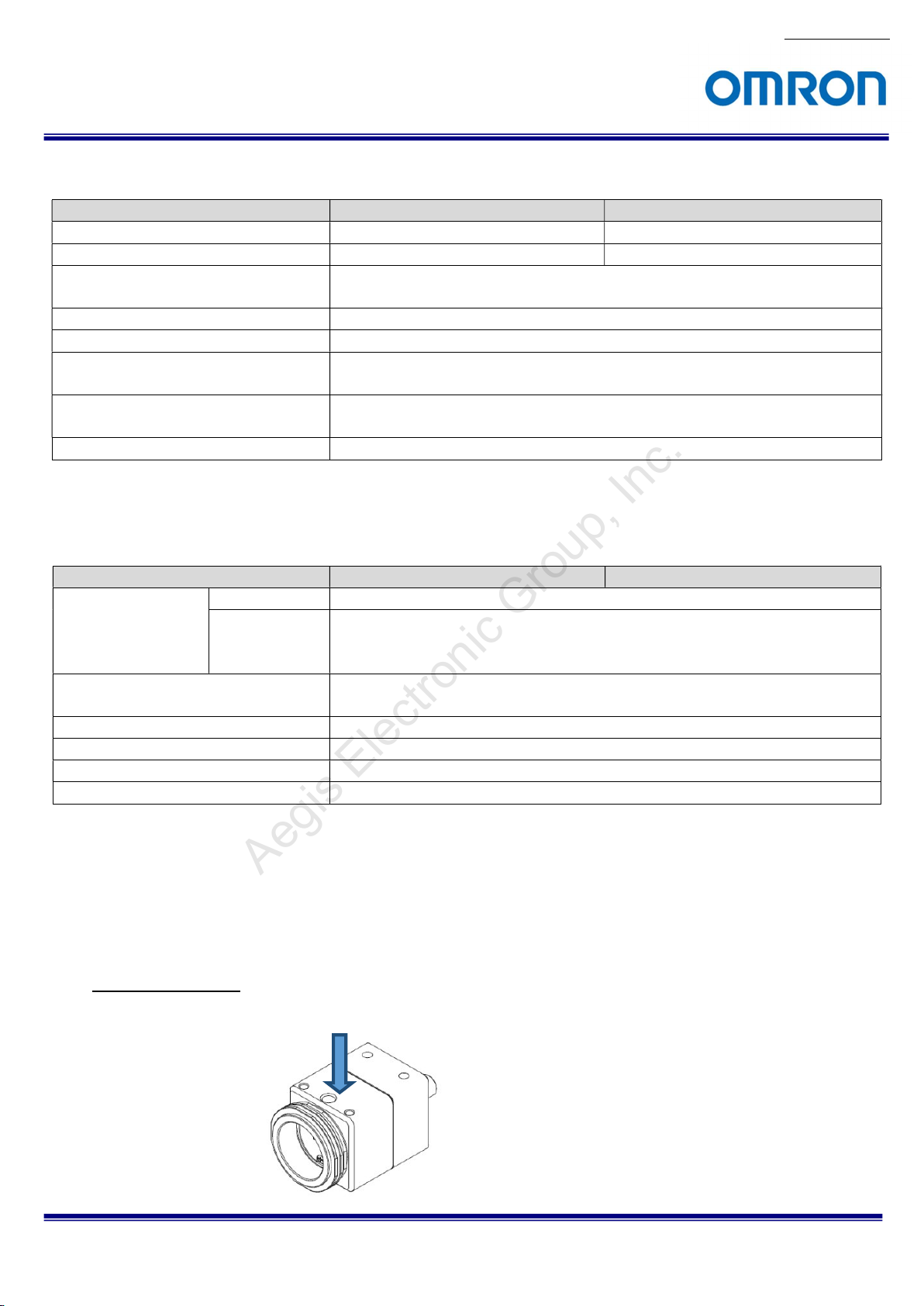
4.4 Environmental Specifications
Model Number STC-SBE132POE STC-SCE132POE
Operational
Temperature / Humidity
Storage Temperature / Humidity Environmental Temperature: -30 to +65 deg. C,
Vibration 20 Hz to 200 Hz to 20 Hz (1.3 Min. / cycle), acceleration 10 G, XYZ 3 directions 30 min. each
Shock Acceleration 38 G, half amplitude 6 mseconds, XYZ 3 directions 3 times each
Standard Compliancy EMS: EN61000-6-2, EMI: EN55011
RoHS RoHS Compliance
Minimum Environmental Temperature -5 deg. C
Maximum (*1) Camera housing temperature (top plate) shall not exceed +62 deg. C
(This corresponds to an environmental temperature of approximately +40 deg. C),
Environmental Humidity: 0 to 85 %RH (No condensation)
Environmental Humidity: 0 to 85 %RH (No condensation)
(*1) When the camera using under the condition that exceeds +40 deg. C environmental temperature, please insure the
camera installs with the appropriate heat dissipation to keep the housing temperature less than +62 deg. C.
If camera has a mounted lens and a tripod with an aluminum plate, this could decrease the camera housing
temperature for heat dissipation.
Taking these steps will maintain the heat rating of the electronic components of the camera.
Upper side of camera
Measuring point
STC-SBE132POE / STC-SCE132POE
Product Specifications and User’s Guide
11/53
Aegis Electronic Group, Inc.
For more information please contact Aegis Electronic Group, Inc. *(888)687-6877 *aegis-g2@aegiselect.com *http://www.aegiselect.com
5 Connector Specifications
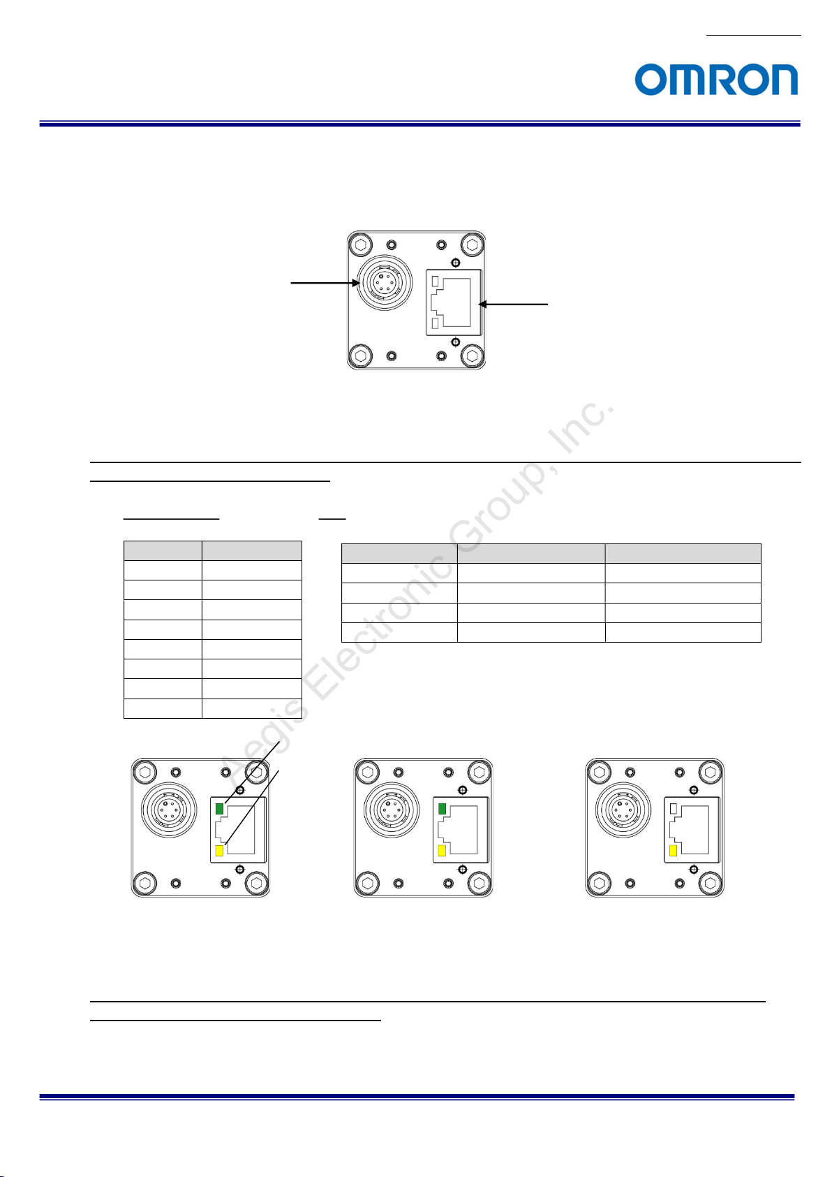
5.1 RJ45 Connector
This product is PoE compliant. Please supply power (+10.8 to +26.4 Vdc) through the power-I/O connector
when using non-PoE-compliant NIC.
Please use a 1GB supported NIC, Network Switcher and LAN cable. Check that the NIC and Network
Switcher being used is “1GB transferring”.
Power-I/O Connector
Pin Assignment LED
Pin No. Signal Name
1 TA+
2 TA3 TB+
4 TC+
5 TC6 TB7 TD+
8 TD-
Camera is powered-on
Green Light ON Yellow Light ON Power ON(1GB NIC)
Green Light OFF Yellow Light OFF Power ON(100MB NIC)
Green Light ON Yellow Light Blinking 1Gb Transferring
Light OFF Yellow Light Blinking 100 Mb Transferring
Green LED
Yellow LED
RJ45 Connector
Green LED Yellow LED Status
Green light: ON
Orange light: Blinking
1 GB Transferring
Green light: OFF
Yellow light: Blinking
100 MB Transferring
No.14S002-08
STC-SBE132POE / STC-SCE132POE
Product Specifications and User’s Guide
12/53

Aegis Electronic Group, Inc.
For more information please contact Aegis Electronic Group, Inc. *(888)687-6877 *aegis-g2@aegiselect.com *http://www.aegiselect.com
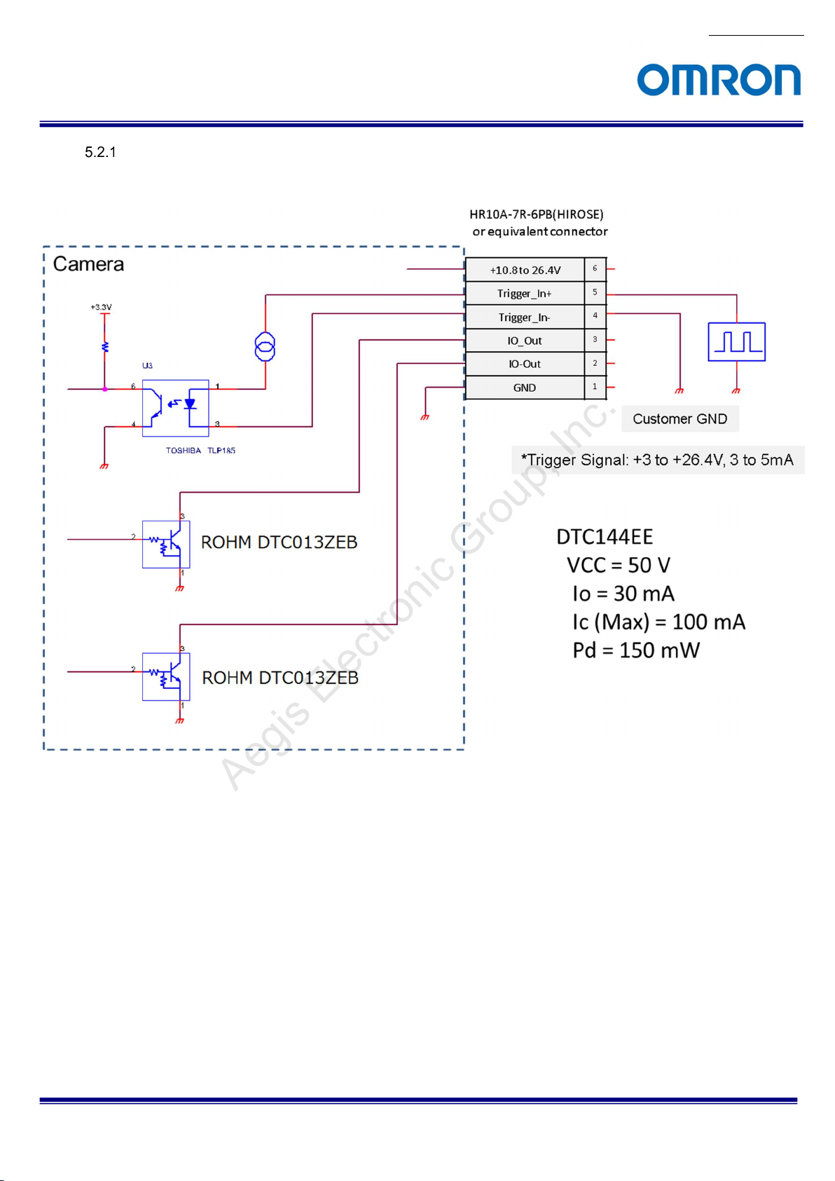
5.2 Power / IO Control Signal Connector
HR10A-7R-6PB (Hirose)r equivalent
This connector is for the power supply (12Vdc) and input /output signals.
Use HR10A-7P-6S (Hirose) or equivalent for the cable side.
Pin assignment
No.14S002-08
Pin No. Signal Name
1 GND IN 0 V
2 I/O-1 OUT +3.3 V Open Collector
3 I/O-2 OUT +3.3 V Open Collector
4
5
6 POWER IN IN +10.8 to +26.4 Vdc
Configuration of I/O-1(Pin No.2) and I/O-2(Pin No.3)
Output pin can be assigned through register setting or GenICam Command.
TRG_In-
(Opt. Isolated -)
TRG_In+
(Opt. Isolated +)
IN /
OUT
IN
IN
I/O-1 (Pin No.2) / I/O-2 (Pin No.3)
1) FrameTriggerWait (initial setting for I/O-1)
2) UserOutput
3) ExposureActive (initial setting for I/O-2)
4) TriggerAuxiliary
5) TriggerInternal
6) SensorReadOut
7) StrobeSignal
Low: Smaller than +1.0 V
High: +3.0 to +26.4 V
* potential difference between TRG_Inand TRG_In+
GenICam command
Voltage
STC-SBE132POE / STC-SCE132POE
Product Specifications and User’s Guide
13/53

Aegis Electronic Group, Inc.
For more information please contact Aegis Electronic Group, Inc. *(888)687-6877 *aegis-g2@aegiselect.com *http://www.aegiselect.com
1) FrameTriggerWait
The user can check the camera condition (camera exposure and image output processing by the
trigger signal with this FrameTriggerWait signal).
This signal is LOW for the period from the trigger input signal to the image output.
2) UserOutput
The status of the UserOutput signal can change with the “UserOutputValue”.
3) ExposureActive
The user can check the exposure time with the ExposureActive signal.
4) TriggerAuxiliary
The TriggerAuxiliary signal is the input trigger signal.
5) TriggerInternal
The TriggerInternal signal is the input trigger signal with the trigger delay time.
6) SensorReadOut
The SensorReadOut signal is the FVAL signal, which is the image output period of the time.
7) StrobeSignal
The StrobeSignal signal is the strobe control signal.
No.14S002-08
STC-SBE132POE / STC-SCE132POE
Product Specifications and User’s Guide
14/53
No.14S002-08
Aegis Electronic Group, Inc.
For more information please contact Aegis Electronic Group, Inc. *(888)687-6877 *aegis-g2@aegiselect.com *http://www.aegiselect.com
Equivalent Circuit for the Input Pin of the I/O Connector
STC-SBE132POE / STC-SCE132POE
Product Specifications and User’s Guide
15/53

Aegis Electronic Group, Inc.
For more information please contact Aegis Electronic Group, Inc. *(888)687-6877 *aegis-g2@aegiselect.com *http://www.aegiselect.com
Typical Input Circuit
STC-SBE132POE / STC-SCE132POE
Product Specifications and User’s Guide
No.14S002-08
16/53
 Loading...