

Omron STC-S133UVC-BLL, STC-S133UVC-ALL, STC-S133UVC-DBLCS, STC-S133UVC-DBLL, STC-S133UVC-ALCS Product Specifications And User's Manual
...Page 1

1.3M USB Camera
STC-S133UVC Color CMOS Cameras
STC-S133UVC-BL (1.3M / No lens mount / IR Cut Filter / Board)
STC-S133UVC-BLL (1.3M / M12 lens mount / IR Cut Filter / Board)
STC-S133UVC-BLCS (1.3M / CS mount / IR Cut Filter / Board)
No.17S021-01
STC-S133UVC-DBL (1.3M / No lens mount / Dual Pass Filter / Board)
STC-S133UVC-DBLL (1.3M / M12 lens mount / Dual Pass Filter / Board)
STC-S133UVC-DBLCS (1.3M / CS mount / Dual Pass Filter / Board)
STC-S133UVC-ALL (1.3M / M12 lens mount / IR Cut Filter / Cased)
STC-S133UVC-ALCS (1.3M / CS mount / IR Cut Filter / Cased)
STC-S133UVC-DALL (1.3M / M12 lens mount / Dual Pass Filter / Cased)
STC-S133UVC-DALCS (1.3M / CS mount / Dual Pass Filter / Cased)
Product Specifications and User’s Guide
STC-S133UVC
Product Specifications and User’s Guide
1/63
Page 2

No.17S021-01
Table of Contents
1 Product Precautions .......................................................................................... 7
2 Warranty ............................................................................................................. 7
3 Introduction ........................................................................................................ 8
3.1 Features .................................................................................................................................... 8
3.2 Product Number Naming Method ........................................................................................... 8
4 Specifications .................................................................................................... 9
4.1 Electronic specifications ......................................................................................................... 9
4.2 Spectral Sensitivity Characteristics ..................................................................................... 11
CMOS Sensor Spectral Sensitivity Characteristics ....................................................................... 11
IR Cut Filter Spectral Sensitivity Characteristics (STC-S133UVC-BL / STC-S133UVC-BLL /
STC-S133UVC-BLCS / STC-S133UVC-ALL / STC-S133UVC-ALCS) .......................................... 12
Dual Pass Filter Spectral Sensitivity Characteristics (STC-S133UVC-DBL /
STC-S133UVC-DBLL / STC-S133UVC-DBLCS / STC-S133UVC-DALL /
STC-S133UVC-DALCS) .................................................................................................................. 12
4.3 Mechanical Specifications ..................................................................................................... 13
STC-S133UVC-BL / STC-S133UVC-DBL ........................................................................................ 13
STC-S133UVC-BLL / STC-S133UVC-DBLL .................................................................................... 13
STC-S133UVC-BLCS / STC-S133UVC-DBLCS ............................................................................... 13
STC-S133UVC-ALL / STC-S133UVC-DALL .................................................................................... 13
STC-S133UVC-ALCS / STC-S133UVC-DALCS ............................................................................... 14
4.4 Environmental Specifications ............................................................................................... 14
4.5 Connector specifications....................................................................................................... 15
STC-S133UVC-BL / STC-S133UVC-BLL / STC-S133UVC-BLCS / STC-S133UVC-DBL /
STC-S133UVC-DBLL / STC-S133UVC-DBLCS .............................................................................. 15
STC-S133UVC-ALL / STC-S133UVC-ALCS / STC-S133UVC-DALL / STC-S133UVC-DALCS ...... 15
4.6 To use the camera .................................................................................................................. 16
Windows system ............................................................................................................................. 16
Linux system ................................................................................................................................... 16
4.7 Other ........................................................................................................................................ 17
5 Dimensions ...................................................................................................... 18
5.1 STC-S133UVC-BL / STC-S133UVC-DBL ............................................................................... 18
STC-S133UVC
Product Specifications and User’s Guide
2/63
Page 3

No.17S021-01
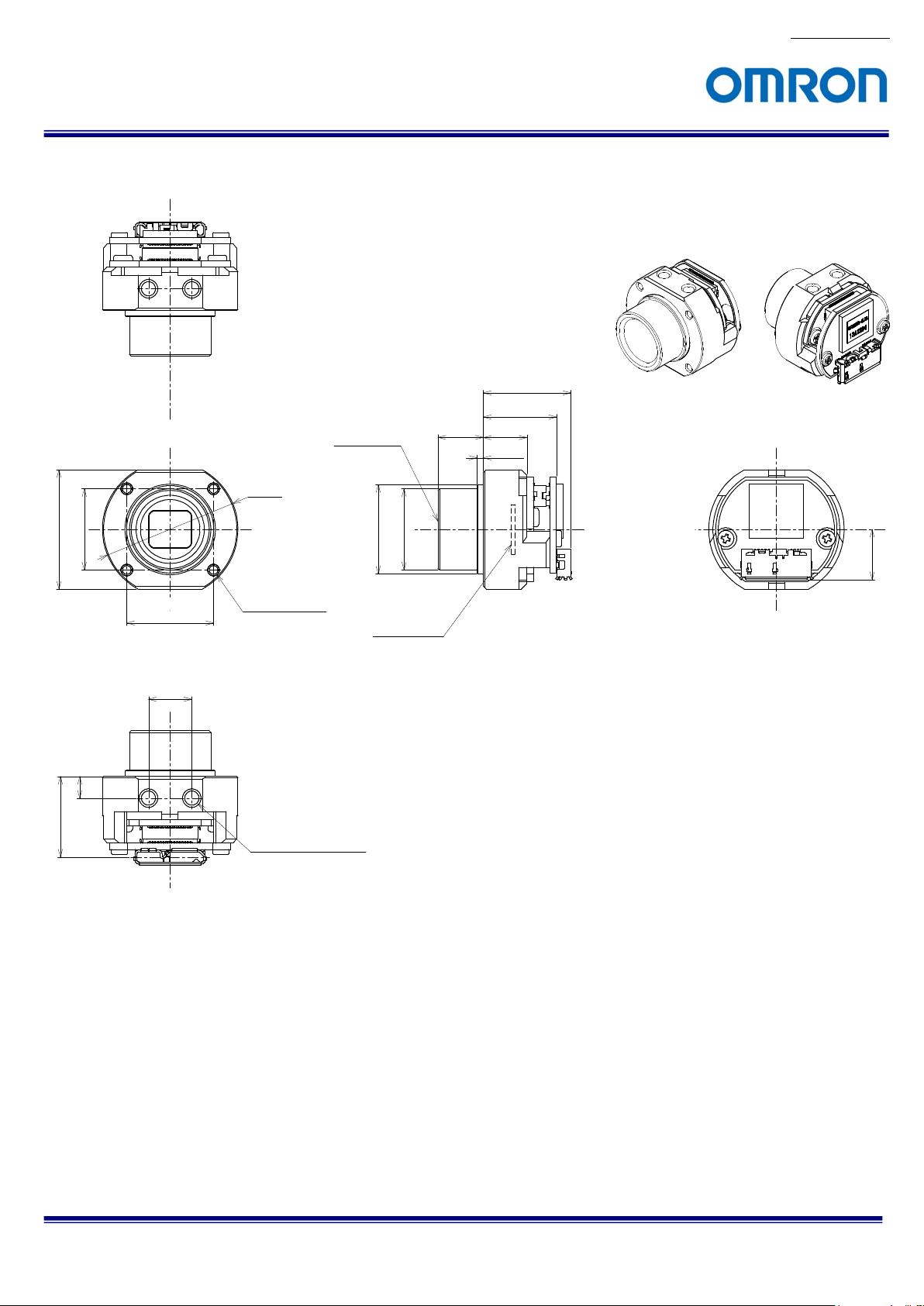
5.2 STC-S133UVC-BLL / STC-S133UVC-DBLL ........................................................................... 19
5.3 STC-S133UVC-BLCS / STC-S133UVC-DBLCS ..................................................................... 20
5.4 STC-S133UVC-ALL / STC-S133UVC-DALL ........................................................................... 21
5.5 STC-S133UVC-ALCS / STC-S133UVC-DALCS ..................................................................... 22
6 Communication control software users guide .............................................. 23
6.1 Requirement software ............................................................................................................ 23
6.2 Connecting configuration ...................................................................................................... 23
6.3 Communication settings........................................................................................................ 23
6.4 Basic operating procedure .................................................................................................... 24
6.5 The descriptions for the buttons .......................................................................................... 25
Read All............................................................................................................................................................................ 25
DSP -> FLASH ................................................................................................................................................................. 25
Reset................................................................................................................................................................................ 25
6.6 The descriptions of the functions ......................................................................................... 26
Menue .............................................................................................................................................................................. 26
Shutter/Gain Tab .............................................................................................................................................................. 27
Lens Tab .......................................................................................................................................................................... 30
OSD Tab .......................................................................................................................................................................... 32
WDR Tab .......................................................................................................................................................................... 34
AE Weight Tab ................................................................................................................................................................. 36
Normal AE Tab ................................................................................................................................................................. 37
Full ME Tab ...................................................................................................................................................................... 38
AE Mask Tab .................................................................................................................................................................... 39
WhiteBalance Tab ............................................................................................................................................................ 40
Gamma Tab ..................................................................................................................................................................... 42
Chroma Tab ..................................................................................................................................................................... 43
Other Tab ......................................................................................................................................................................... 44
Privacy Mask Tab ............................................................................................................................................................. 45
Day&Night Tab ................................................................................................................................................................. 47
Aperture Tab .................................................................................................................................................................... 48
Analog Tab ....................................................................................................................................................................... 48
Blemish Pixel Tab ............................................................................................................................................................ 49
Info. Tab ........................................................................................................................................................................... 49
Field Table........................................................................................................................................................................ 49
One Shot .......................................................................................................................................................................... 50
7 Camera setting by the OSD ............................................................................. 51
STC-S133UVC
Product Specifications and User’s Guide
3/63
Page 4

No.17S021-01
7.1 OSD operation by camera control software ......................................................................... 51
OSD menu ....................................................................................................................................... 52
SETUP MENU .............................................................................................................................................................. 52
SHUTTER/AGC ........................................................................................................................................................... 53
WHITE BAL .................................................................................................................................................................. 54
PICT ADJUST .............................................................................................................................................................. 56
DEFOG......................................................................................................................................................................... 57
WDR/ATR ..................................................................................................................................................................... 58
Day/Night ..................................................................................................................................................................... 59
DNR.............................................................................................................................................................................. 59
PRIVACY ...................................................................................................................................................................... 60
LANGUAGE ................................................................................................................................................................. 61
CAMERA RESET ......................................................................................................................................................... 61
SAVE ALL ..................................................................................................................................................................... 61
8 Revisions History ............................................................................................ 62
STC-S133UVC
Product Specifications and User’s Guide
4/63
Page 5
No.17S021-01
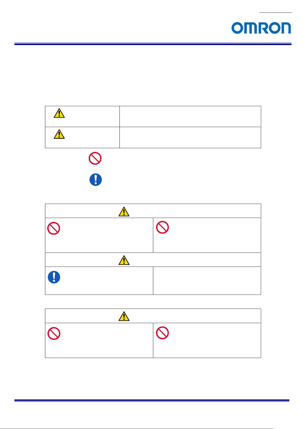
Precautions for safe use
Please read carefully this “Precautions for safe use” before use the camera. Then the camera uses correctly with
agreeing with below notes.
In this “Precautions for safe use”, notes divides into “Warning” and “Caution” to use the camera safety and prevent to
harm and damage.
This shows, assumption for possibility of serious accident leading death or
Warning
Caution
About Graphic
symbols
[Environment / condition]
serious injury if ignore this note and camera uses incorrectly.
This shows, assumption for possibility of bear the damage or physical
damage if ignore this note and camera uses incorrectly.
This symbol shows general prohibition.
This symbol shows completion or instruction.
Warning
Do not use flammable or explosiveness
atmospheres.
This will cause of personal injury or fire.
Caution
Use and store under specified environmental
conditions (Vibration, shock, temperature,
humidity) in the specifications for this camera.
This will cause of fire or damage the camera.
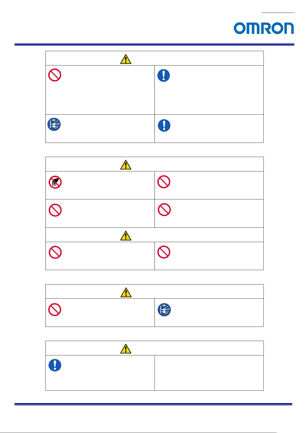
[Installation and cable wiring]
Warning
Do not use with out of power voltage range
that is specified in the specifications for this
camera.
This will cause of fire, electrification or
malfunction.
Do not use for “safety for human body” related
usage.
This camera is designed for use “do not harm
human body immediately” if by any chance the
camera has malfunction.
Do not wrong wiring.
This will cause of fire or malfunction.
STC-S133UVC
5/63
Product Specifications and User’s Guide
Page 6
No.17S021-01
Caution
Do not grounding DC power (+) of all devices
that are connect to the camera.
The camera housing is connecting to 0 V line of
camera inside circuit.
There is a risk of short circuit between camera
inside ciurcuit and frame ground.
This will cause of malfunction.
It is necessary to wiring with turn off the camera.
This will cause of electrification or malfunction.
[Usage instruction]
It is necessary to wiring and mounting that is
specified in the specifications for this camera.
This will cause of fire or malfunction.
It is necessary to mounting the camera without
stress for the cable.
This will case of electrification or fire.
Warning
Do not touch the terminal and PCB board
While turn on the camera.
This will cause of electrification or accident
caused by malfunction.
Do not use without usage that is specified in
the specifications for this camera.
This will cause of personal injury or malfunction.
Caution
Do not push contamination into opening of
the camera.
This will cause of electrification or malfunction.
[Maintenance]
Caution
Do not disassemble or repair the camera.
This will cause of fire, electrification or
malfunction.
[Disposal]
Do not put combustibles near the camera.
This will cause of fire.
Do not push metals including screw driver into
radiation holes.
This will cause of electrification or malfunction.
Do not block the radiation holes.
This will cause of fire due to increase the
camera inside temperature.
It is turn off the camera when maintaining or
inspecting the camera.
This will cause of electrification.
Caution
It is necessary to dispose as industrial waste.
STC-S133UVC
Product Specifications and User’s Guide
6/63
Page 7

1 Product Precautions
Do not give shock to the camera.
Do not haul or damage the camera cable.
Do not wrap the camera with any material while using the camera. This will cause the internal camera
temperature to increase.
When the camera moving or using the place that temperature difference is extreme, countermeasure for
dew condensation (heat removal / cold removal) is necessary.
While the camera is not using, keep the lens cap on the camera to prevent dust or contamination from getting
in the sensor or filter and scratching or damaging it.
Do not keep the camera under the following conditions.
・ In wet, moist, high humidity or dusty place
・ Under direct sunlight
・ In extreme high or low temperature place
・ Near an object that releases a strong magnetic or electric filed
・ Place with strong vibrations
Apply the power that satisfies the specified in specifications for the camera.
The defective pixels may appear due to the sensor characteristics.
Use below recommend materials (or equivalent materials) to clean the surface of glass.
・ Air dust: Non Freon air duster (NAKABAYASHI Co., LTD.)
・ Alcohol: Propan-2-ol (SAN’EI KAKO Co., LTD.)
・ Non-woven: nikowipe clean room (NKB)
Use a soft cloth to clean the camera.
No.17S021-01
2 Warranty
■Warranty period
One year after delivery (However, the camera had malfunction with camera uses correctly)
In below case for a fee even within warranty period.
・The malfunction caused by incorrect usage, incorrect modify or repair.
・The malfunction caused by external shock including the camera dropping after delivery the camera.
・The malfunction caused by fire, earthquake, flood disaster, thunderbolt struck, other natural disaster or
wrong voltage.
■Warranty coverage
Exchange or repair the malfunction camera if the malfunction is occurred by our responsibility.
“Warranty” mean is warranty for the delivered camera itself. Please accept the induction damage by the
camera malfunction is not included.
STC-S133UVC
Product Specifications and User’s Guide
7/63
Page 8
3 Introduction
This document describes the specifications of the following cameras
STC-S133UVC-BL / STC-S133UVC-BLL / STC-S133UVC-BLCS (IR Cut Filter, Board models)
STC-S133UVC-DBL / STC-S133UVC-DBLL / STC-S133UVC-DBLCS (Dual Pass Filter, Board models)
STC-S133UVC-ALL / STC-S133UVC-ALCS (IR Cut Filter, Cased models)
STC-S133UVC-DALL / STC-S133UVC-DALCS (Dual Pass Filter, Cased models)
3.1 Features
・USB3.0 USB Video Class 1.1 compliant
・1/3.2” 1.27M CMOS Sensor (Sony, ISX017)
・Small camera
・Gain, shutter and color adjustment functions
・Flip image function
・Day / Night function
・Lens vignetting and distortion correction
・Shading correction
・Configurable many parameters through the control software
・Wide dynamic range (ATR-EX) and defog function
・Pixel blemish correction
・OSCD (On Screen Character Display) is available for the parameters configuration (OSD)
3.2 Product Number Naming Method
No.17S021-01
STC-S133UVC-xBL
BL: Angle USB, No lens mount, Board
BLL: Angle USB, M12 lens mount, Board
BLCS: Angle USB, CS mount, Board
ALL: Angle USB, M12 lens mount, Cased
ALCS: Angle USB, CS mount, Cased
Optical Filter
None: IR Cut Filter
D: Dual Pass Filter
UVC: USB Video Class
STC-S133UVC
Product Specifications and User’s Guide
8/63
Page 9
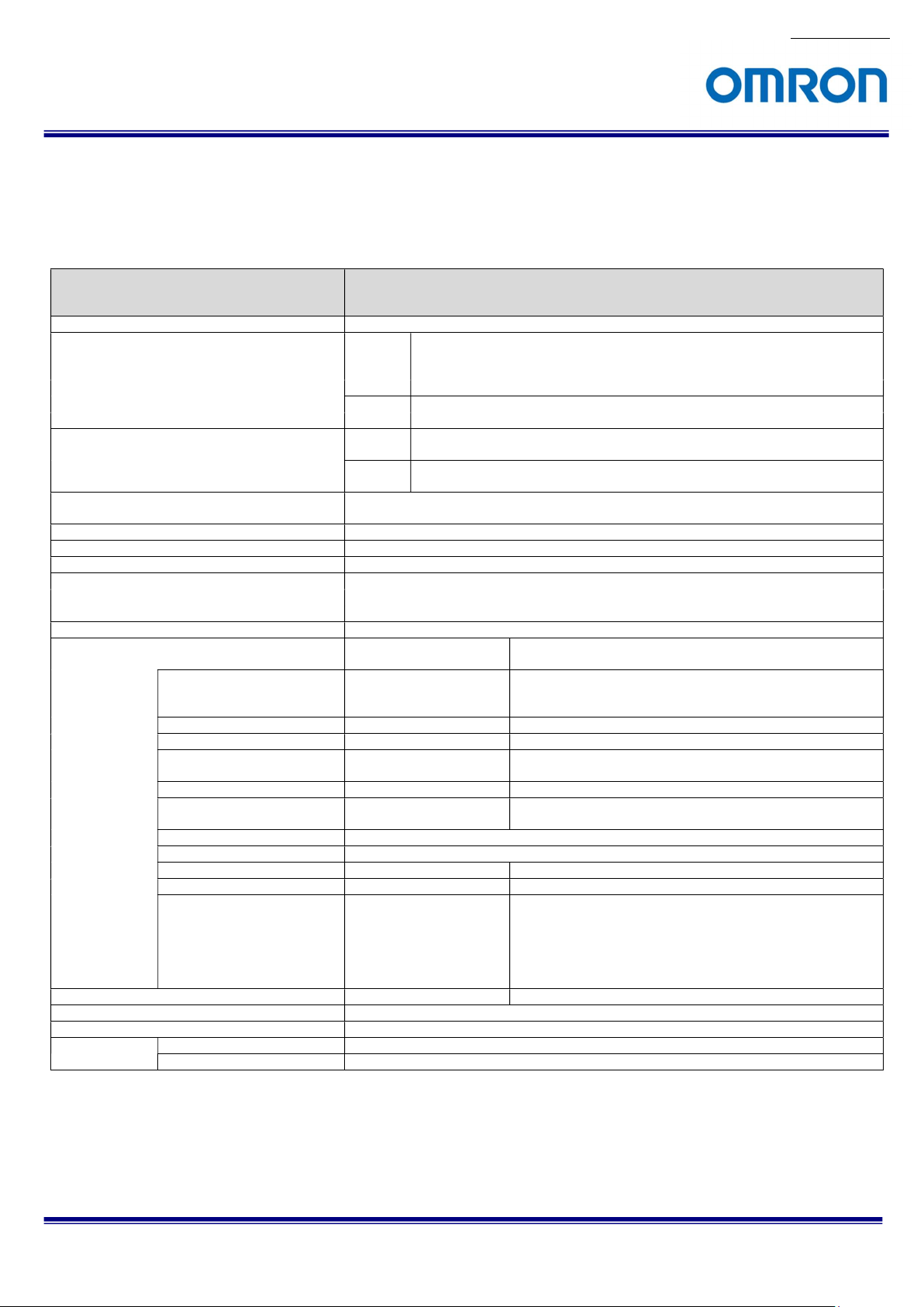
4 Specifications
4.1 Electronic specifications
No.17S021-01
Model Number STC-S133UVC-BL / STC-S133UVC-BLL / STC-S133UVC-BLCS /
STC-S133UVC-ALL / STC-S133UVC-ALCS / STC-S133UVC-DALL / STC-S133UVC-DALCS
Image sensor 1/3.2" 1.27M Progressive CMOS (SONY ISX017)
Video signal format USB3.0
USB2.0 800 (H) x 600 (V) 25 fps, 640 (H) x 480 (V) 30 / 25 fps with image center ROI output
Chip size USB3.0
USB2.0
Cell size
Shutter type Rolling shutter
Sensitivity (*1) 220 Lux
Sync system Internal
Compliant standard USB3.0 / USB2.0
Support OS Windows 7,10 / Linux (Ubuntu, CentOS)
Camera
functions
Electronic shutter 1/60 to 1/10,000 seconds
Gain AGC only AGC / Fixed gain 0 to 40 dB
White balance Auto White Balance only Auto white balance / Manual / Push to set
Image flip Horizontal and vertical flip
Gamma N/A Manual / Straight
Privacy masking N/A 16 frames (Color, size and position are adjustable individually)
Color adjustment Hue and saturation are adjustable
Image adjustment Brightness and contrast are adjustable
Day / Night N/A Support
Lens correction N/A Vignetting, distortion and shading correction
Others Back light compensation /
Communication N/A UART communication by CDC 115,200bps
OSD Available for USB3.0 connection with CDC
Interface USB3.0 micro B type connector
Power Input voltage +5 V USB Bus power
Adjustable functions with
(Auto only for USB2.0)
STC-S133UVC-DBL / STC-S133UVC-DBLL / STC-S133UVC-DBLCS
1,280 (H) x 720 (V) 60 / 50 / 30 / 25 fps, 1,280 (H) x 960 (V) 30 / 25 fps
(Default: 1,280 (H) x 720 (V) 60 fps)
(Default: 800 (H) x 600 (V) 25 fps)
4.48 (H) x 2.52 (V) mm (1,280 (H) x 720 (V)) /
4.48 (H) x 3.36 (V) mm (1,280 (H) x 960 (V))
2.80 (H) x 2.10 (V) mm (800 (H) x 600 (V)) /
2.24 (H) x 1.68 (V) mm (640 (H) x 480 (V))
3.5 (H) x 3.5 (V) µm
USB Video Class (UVC) 1.1
Communication Device Class (CDC)
Adjustable functions with communication
UVC Viewer
1/60 (1/50) to 1/605,000 seconds Auto / Fixed
Auto
Normal / Horizontal flip / Vertical flip / Horizontal and vertical flip
only
Flicker correction
Noise reduction (2D) / Negative/Positive image /
(Default: Off)
Pixel blemish correction / WDR /
Defog / Back light compensation /
Flicker correction /
High brightness correction /
False color correction
Consumption Max: 1.0W, Typical 0.8 W
Default: Bold
STC-S133UVC
9/63
Product Specifications and User’s Guide
Page 10
Precautions
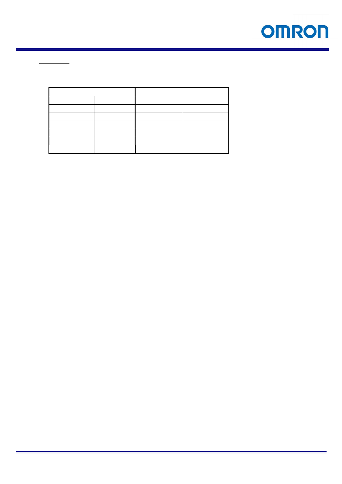
(*1) The sensitivity is measuring the luminance when white level achieved 100 % in below conditions.
Camera Setting Environment
Parameter Setting Parameter Setting
Gain Up 0 dB Light Source Light Box (White)
AGC Off Color temperature 5,100K
White Balance Optimum Lens
Electrical Shutter 1/30 seconds F on Lens F5.6
Black Level Optimum Target Luminance IM-600 (Topcon)
Gamma Factory Setting
No.17S021-01
STC-S133UVC
10/63
Product Specifications and User’s Guide
Page 11
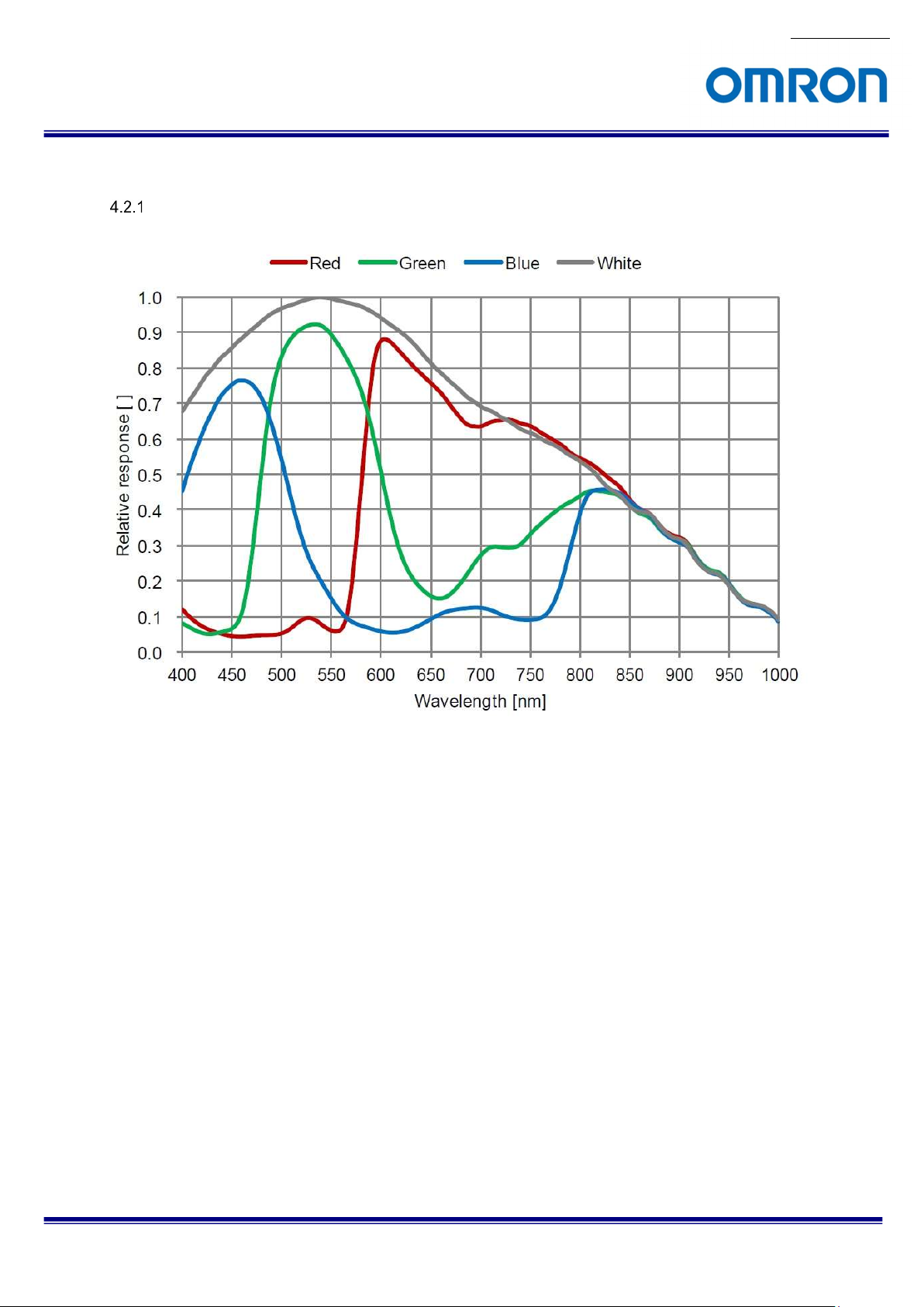
4.2 Spectral Sensitivity Characteristics
CMOS Sensor Spectral Sensitivity Characteristics
No.17S021-01
STC-S133UVC
Product Specifications and User’s Guide
11/63
Page 12
No.17S021-01
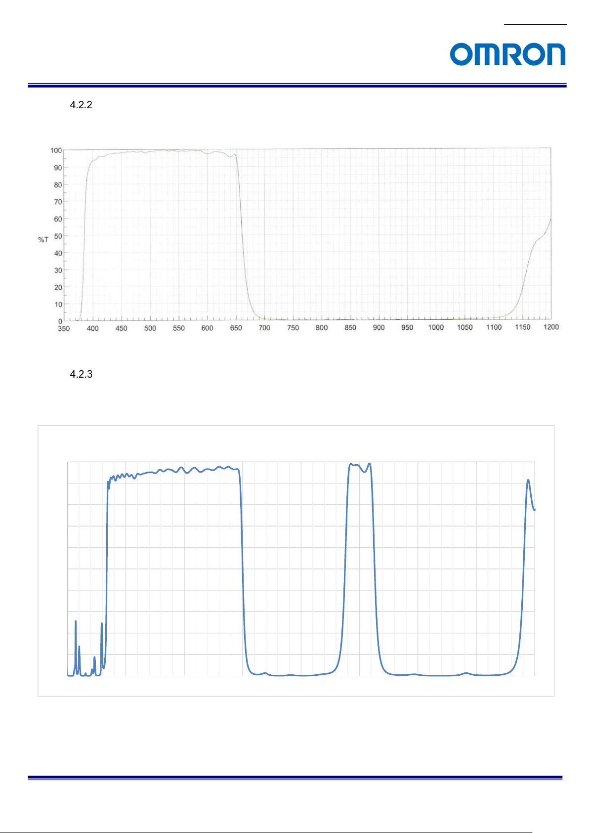
IR Cut Filter Spectral Sensitivity Characteristics
(STC-S133UVC-BL / STC-S133UVC-BLL / STC-S133UVC-BLCS /
STC-S133UVC-ALL / STC-S133UVC-ALCS)
Dual Pass Filter Spectral Sensitivity Characteristics
(STC-S133UVC-DBL / STC-S133UVC-DBLL / STC-S133UVC-DBLCS /
STC-S133UVC-DALL / STC-S133UVC-DALCS)
Transmittance (%)
100
90
80
70
60
50
40
30
20
10
0
350 450 550 650 750 850 950 1050 1150
STC-S133UVC
Product Specifications and User’s Guide
12/63
Page 13
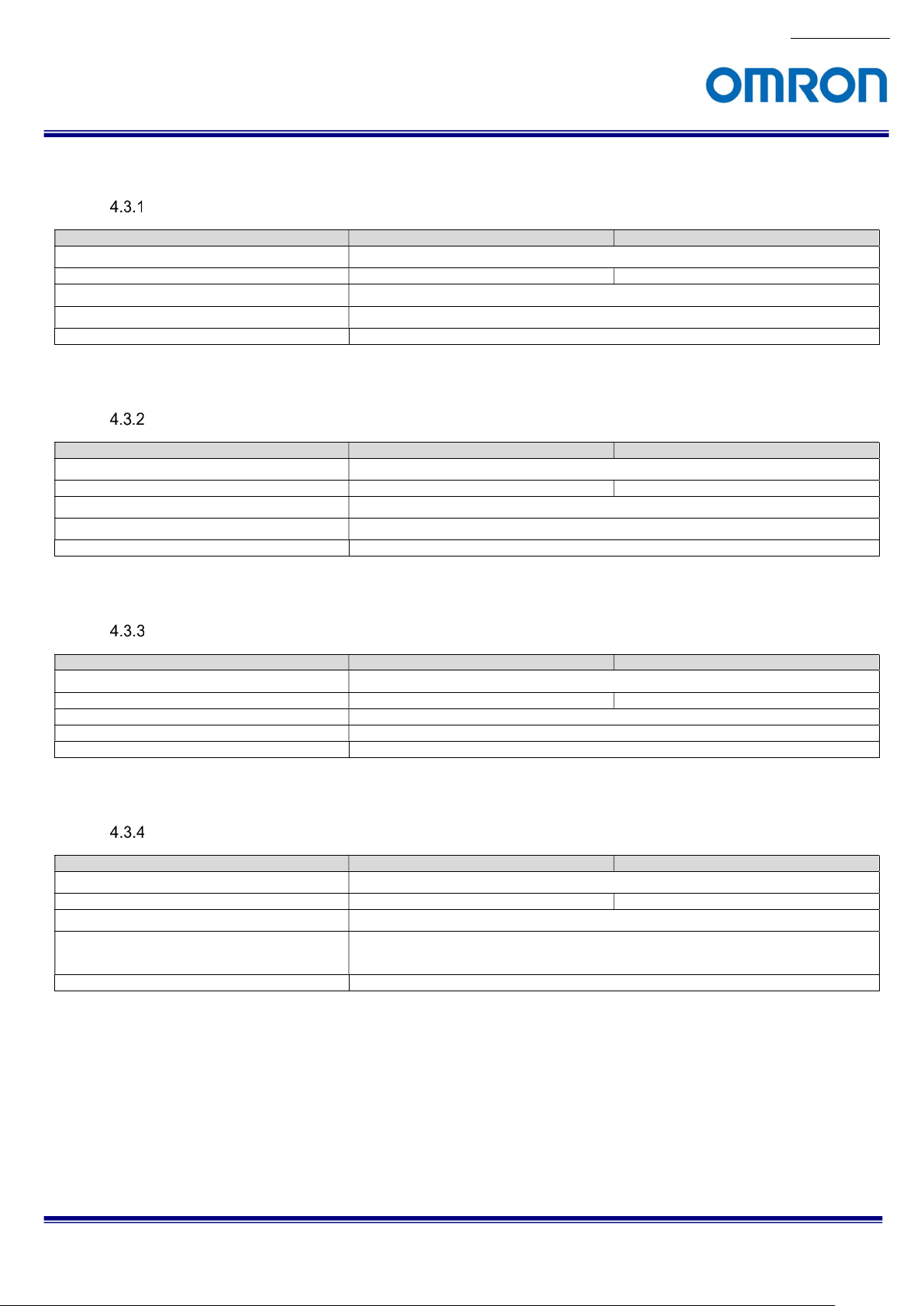
4.3 Mechanical Specifications
STC-S133UVC-BL / STC-S133UVC-DBL
Model Number STC-S133UVC-BL STC-S133UVC-DBL
Dimensions (*1)
Optical Filter IR Cut Filter built in Dual Pass Filter built in
Lens Mount
Camera Mounting
Weight Approximately 8 g
M2 screw holes (Four on front, two on top and bottom plate)
23 (W) x 20 (H) x 15.1 (D) mm
No lens mount
(*1) Excluding projection
STC-S133UVC-BLL / STC-S133UVC-DBLL
Model Number STC-S133UVC-BLL STC-S133UVC-DBLL
Dimensions (*1)
Optical Filter IR Cut Filter built in Dual Pass Filter built in
Lens Mount
Camera Mounting
Weight Approximately 13 g
M2 screw holes (Four on front, two on top and bottom plate)
25 (W) x 22 (H) x 24.5 (D) mm
M12 x P0.5
(*1) Excluding projection
STC-S133UVC-BLCS / STC-S133UVC-DBLCS
No.17S021-01
Model Number STC-S133UVC-BLCS / STC-S133UVC-DBLCS
Dimensions (*1)
Optical Filter IR Cut Filter built in Dual Pass Filter built in
Lens Mount CS mount
Camera Mounting M2 screw holes (Tow on Top and bottom plate)
Weight Approximately 12 g
φ28 x 21.7 (D) mm
(*1) Excluding projection
STC-S133UVC-ALL / STC-S133UVC-DALL
Model Number STC-S133UVC-ALL STC-S133UVC-DALL
Dimensions (*1)
Optical Filter IR Cut Filter built in Dual Pass Filter built in
Lens Mount
Camera Mounting
M2.5 screw holes (Two on Top, bottom and both side plate)
Weight Approximately 23 g
25 (W) x 25 (H) x 18 (D) mm
M12 x P0.5
M2 screw holes (Four on front plate)
(*1) Excluding projection
STC-S133UVC
Product Specifications and User’s Guide
13/63
Page 14
No.17S021-01
STC-S133UVC-ALCS / STC-S133UVC-DALCS
Model Number STC-S133UVC-ALCS / STC-S133UVC-DALCS
Dimensions (*1)
Optical Filter IR Cut Filter built in Dual Pass Filter built in
Lens Mount CS mount
Camera Mounting M2.5 screw holes (Two on Top, bottom and both side plate)
Weight Approximately 24 g
25 (W) x 25 (H) x 25.6 (D) mm
(*1) Excluding projection
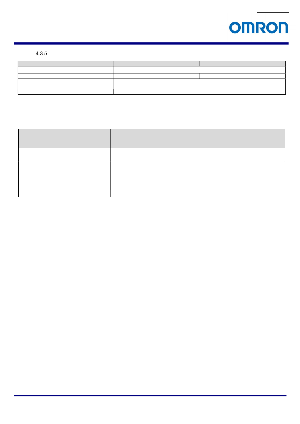
4.4 Environmental Specifications
Model Number
STC-S133UVC-ALL / STC-S133UVC-ALCS / STC-S133UVC-DALL / STC-S133UVC-DALCS
Operational Temperature / Humidity Environmental Temperature: 0 to +55 deg. C,
Storage Temperature / Humidity Environmental Temperature: -25 to +75 deg. C,
Vibration 20 Hz to 200 Hz to 20 Hz (5 min. / cycle), acceleration 10 G, XYZ 3 directions 30 min. each
Shock Acceleration 38 G, half amplitude 6 ms, XYZ 3 directions 3 times each
RoHS RoHS Compliant
STC-S133UVC-BL / STC-S133UVC-BLL / STC-S133UVC-BLCS /
STC-S133UVC-DBL / STC-S133UVC-DBLL / STC-S133UVC-DBLCS /
Environmental Humidity: 0 to 80 %RH (No condensation)
Environmental Humidity: 0 to 80 %RH (No condensation)
STC-S133UVC
14/63
Product Specifications and User’s Guide
Page 15
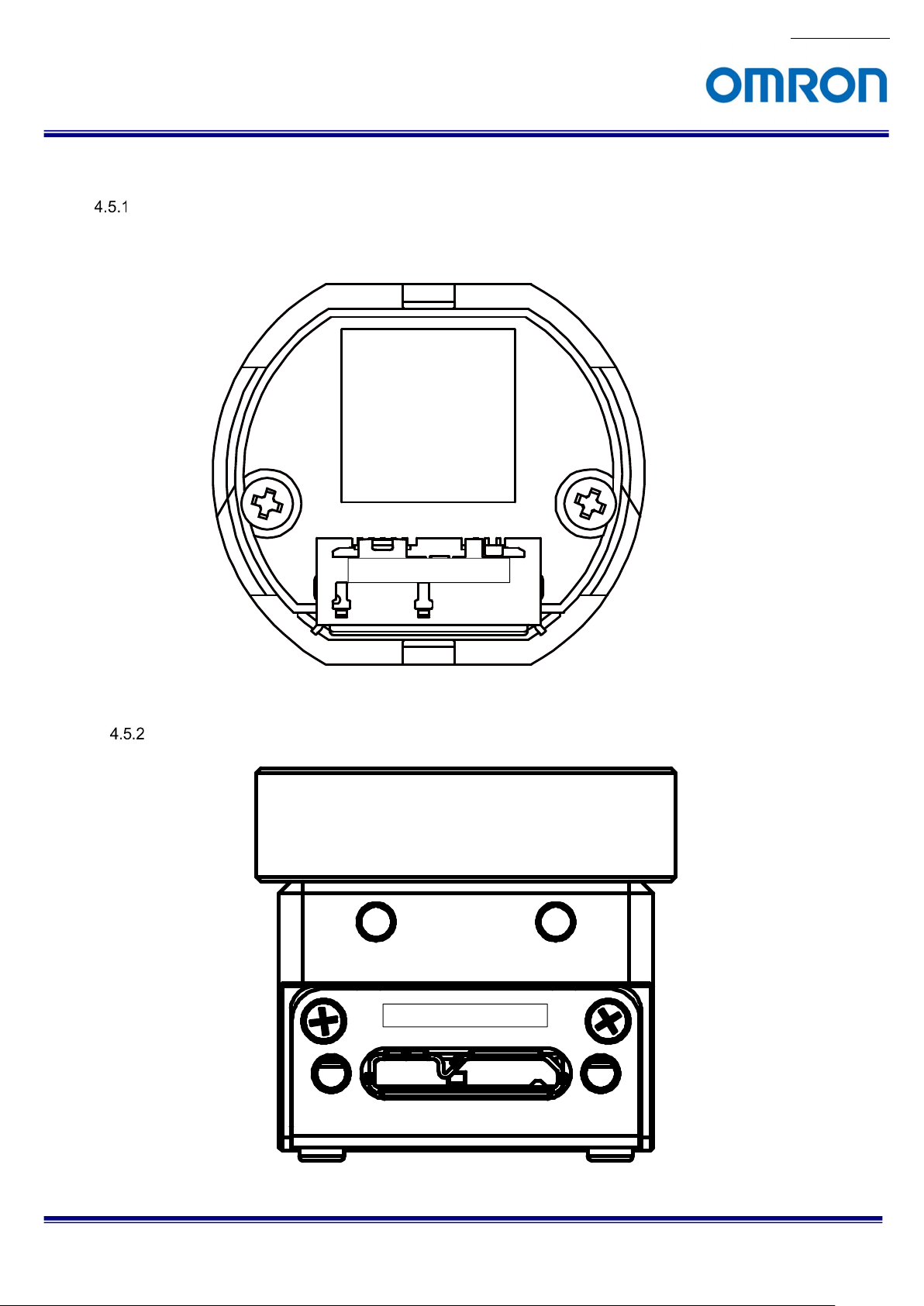
4.5 Connector specifications
STC-S133UVC-BL / STC-S133UVC-BLL / STC-S133UVC-BLCS / STC-S133UVC-DBL /
STC-S133UVC-DBLL / STC-S133UVC-DBLCS
Bottom of camera
STC-S133UVC-ALL / STC-S133UVC-ALCS / STC-S133UVC-DALL / STC-S133UVC-DALCS
No.17S021-01
USB3.0 micro B type
USB3.0 micro B type
STC-S133UVC
Product Specifications and User’s Guide
15/63
Page 16
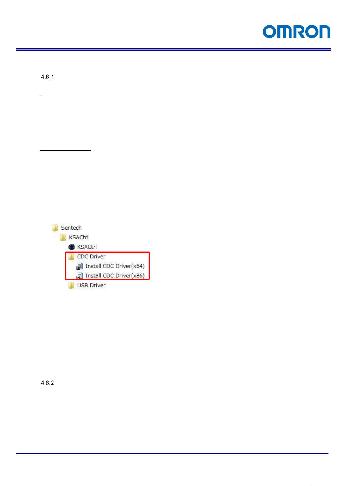
4.6 To use the camera
Windows system
Requirement software
1) Camera control software: KSACtrl (version 2.02 or newer)
2) OSD software: S133Control
(The camera settings are changeable with on screen display)
* UVC camera supported viewer software (UVC Viewer) is required to obtain the image.
Software installation
CDC driver for communicate to the camera, install before camera connects to the PC.
Please follow below procedure.
1) Install KSACtrl.
2) Install CDC driver by selecting “Install CDC driver” under “KSACtrl” under “Sentech” at Program menu.
Please select correct installer from 32bits (x86) or 64bit (x64).
* CDC driver is installing automatically when the camera connecting to the Windows10 PC.
(CDC driver manual install is not necessary)
No.17S021-01
3) The driver is installing automatically when the camera connects to PC after installed CDC driver.
The driver installing may take few minutes.
4) The camera disconnects from PC after installing the driver correctly.
5) The camera connects to PC.
The image can obtain by UVC Viewer and camera settings are changeable from KSACtrl or OSD software
(S133Control)
Linux system
We’ve confirm the image with Cheesa and Guvcview on Ubuntu and CentOS Linux.
The camera settings are changeable from OSD software (S133Ctrol)
STC-S133UVC
Product Specifications and User’s Guide
16/63
Page 17

No.17S021-01
800 (H) x
600 (V) 25
fps, 640 (H) x
480
(V): 30fps / 25
fps
* with the image center ROI output
4.7 Other
When the camera connecting to USB2.0 port, the center ROI image is output and field of view becomes narrow.
When the camera connecting to USB2.0 port, the image stream may stop while camera settings are adjusting.
USB3.0 1,280 (H) x 720 (V): 60 / 50 / 30 / 25 fps, 1,280 (H) x 960 (V): 30 / 25 fps
USB2.0
STC-S133UVC
Product Specifications and User’s Guide
17/63
Page 18
20
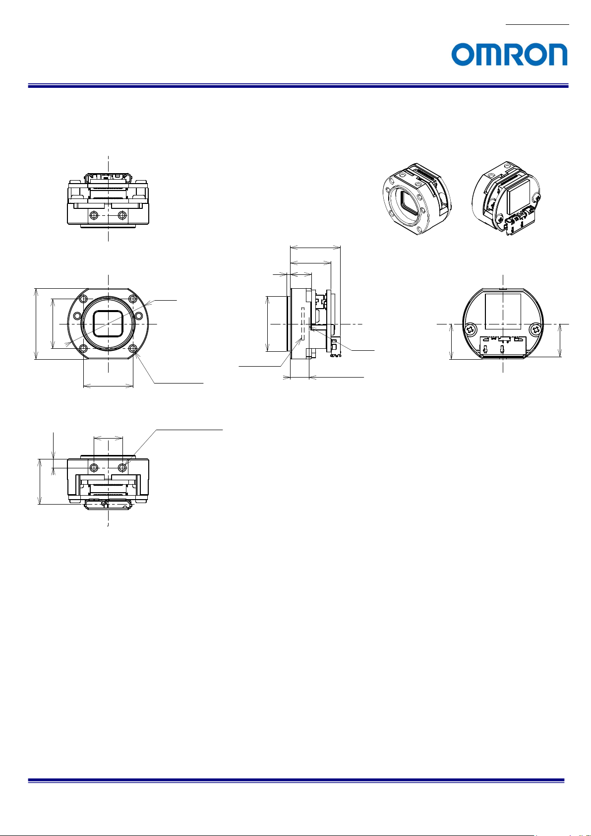
5 Dimensions
5.1 STC-S133UVC-BL / STC-S133UVC-DBL
φ 23
No.17S021-01
(14.1)
11.5
6
1
14
14
8
2.5
(12.85)
4-M2 Depth2.5
4-M2 Depth2.5
(2-M2 on other side)
φ 15.5
Optical Filter
Image
4.87 (in Air)
(10)
9.3
Unit: mm
STC-S133UVC
Product Specifications and User’s Guide
18/63
Page 19
22
5.2 STC-S133UVC-BLL / STC-S133UVC-DBLL
M12 X P0.5
8.4
No.17S021-01
(16.1)
13.5
8
1.2
φ 25
15
16
8
4
(14.85)
4-M2 Depth3.0
4-M3 Depth3.0
(2-M3 on other side)
φ 15
φ 16.5
Optical Filter
9.3
Unit: mm
STC-S133UVC
Product Specifications and User’s Guide
19/63
Page 20

(20.45)
5.3 STC-S133UVC-BLCS / STC-S133UVC-DBLCS
CS mount
No.17S021-01
(21.7)
19.1
13.6
7.6
φ 23
8
10.1
(2.5)
φ 28
Optical Filter
4-M2 Depth2.5
(2-M2 on other side)
20
M2 Screw plate
9.3
Unit: mm
STC-S133UVC
Product Specifications and User’s Guide
20/63
Page 21

(12.85)
5.4 STC-S133UVC-ALL / STC-S133UVC-DALL
25
14
R1.6
M12x0.5
No.17S021-01
18
2.7
10.4
3.2
1.2
25
14
4-M2 Depth3.0
12
2.7
18
φ 15
φ 16.5
2-M2.5 Depth3.0
(Top, bottom and both sides)
2-M2 Depth4.0
7
15.27 (in Air)
Both sides are same
10.8
Image
Optical Filter
Unit: mm
STC-S133UVC
Product Specifications and User’s Guide
21/63
Page 22

20.45
5.5 STC-S133UVC-ALCS / STC-S133UVC-DALCS
25
R1.6
CS Mount
10.3
7.6
No.17S021-01
25.6
18
2.7
25
12
(10.3)
(2.7)
18
φ 28
10.8
Optical Filter
14.6
Both sides are same
2-M2.5 Depth3.0
(Top, bottom and both sides)
2-M2 Depth4.0
Unit: mm
STC-S133UVC
Product Specifications and User’s Guide
22/63
Page 23

6 Communication control software users guide
6.1 Requirement software
1) Control software KSACtrl v2.02 or newer
6.2 Connecting configuration
When KSACtrl (v2.02 or newer) is installing, the installation menu for CDC driver is added to the program menu.
Please install CDC driver before STC-S133UVC camera connects to the PC.
6.3 Communication settings
UART (RS232C compliant), Binary communication
Setting Value
Baud rate 115,200 bps
Data bit 8 bits
Parity None
Stop bit 1 bit
Flow control None
No.17S021-01
STC-S133UVC
Product Specifications and User’s Guide
23/63
Page 24

6.4 Basic operating procedure
The camera communication software (KSACtrl) is usable after install KSACtrl software.
Start KSACtrl software.
No.17S021-01
Select the COM port number to use the camera communication by selecting “Port Setting” under “Comm (C)” in the
menu.
Select “Read All” button to read all of the register information from the camera.
All of the camera settings are configurable through the camera control software.
STC-S133UVC
Product Specifications and User’s Guide
24/63
Page 25

6.5 The descriptions for the buttons
Read All
Read out all camera settings in the camera. Please select this button every time when the camera power is
turning on.
This software stores as the camera default settings in to the Flash memory on the camera when first time select
“Read All” button after run KSACtrl software.
* The camera settings are not reflecting as default data from the second time select “Read all” button.
Note.1: It will take time to read out all camera settings while the image streaming.
It will not take long time when reading out the camera settings without the image stream
Note.2: Please read out all camera settings without the image streaming while the camera connects to USB2.0
port.
It is possible to stop freeze the image streaming if read out all camera settings while the image
streaming.
DSP -> FLASH
Save the camera settings (changed settings) in to the Flash memory on the camera.
All changed camera settings save to the Flash memory at once.
Reset
N/A
No.17S021-01
STC-S133UVC
Product Specifications and User’s Guide
25/63
Page 26

6.6 The descriptions of the functions
Menue
File(F)
Save As[DSP->File]…
Read the camera settings and creates the camera settings file.
Open[File->DSP]…
Load the camera settings from the camera settings file then apply to the camera.
Open[File->Flash]…
Load the camera settings from the camera settings file then apply to the camera and save the camera settings
in to the flash memory.
Comm (C)
Same function as “Read All” and “DSP->Flash” button located in bottom of the software.
Mode (M)
Adjustment
The individual camera settings are adjustable.
One Shot
The camera settings save to the file and load from the camera setting file to the camera.
No.17S021-01
STC-S133UVC
Product Specifications and User’s Guide
26/63
Page 27

Shutter/Gain Tab
Exposure Control Mode (Default: AE)
AE
The brightness level is adjusting with the shutter and gain automatically.
It is necessary to set the shutter and the gain at “Normal AE” Tab.
HOLD
The shutter and gain are holding. When the brightness of the target is changed, the camera does not adjust the brightness.
Scale ME
The brightness level is adjusting by the shutter and gain settings.
User Preset ME
The brightness level is adjusting by the preset shutter and gain.
Full ME
The brightness level is adjusting the manually by the shutter and gain at “Full ME” Tab.
Convergence luminance
Set the convergence luminance for AE. (Default: 12,828)
AE convergence speed setting
Set the AE convergence speed. When set greater value, the AE convergence speed increases. (Default: 216)
Frame count for dead band
Set the number of the frame that uses for the AE control start judgement. (Default: 2)
Dead band / AE tracking AE
Set the AE convergence stop condition.
AE convergence is stopped when AE error is less than this setting and keeps the same condition more than three frames.
(Default: 26)
Dead Band / AE convergence AE
Set the AE convergence start condition.
AE convergence starts when AE error is greater than this setting and keeps the same condition more than the frame counter
of the dead band. (Default: 4)
EV correction
Set the amount of the exposure. (Default: 0)
No.17S021-01
STC-S133UVC
Product Specifications and User’s Guide
27/63
Page 28

No.17S021-01
Minimum / Maximum shutter time, Minimum / Maximum Gain
Set the limit for the shutter and gain.
Shutter Priority time
The AE becomes the shutter prioritized AE when setting other than “0” while AE mode.
It is necessary to select the value that between the minimum and maximum shutter time.
The shutter is fixed as the selected shutter time and the brightness level is adjusting by the gain. (Default: 0)
Gain Priority setting
The AE becomes the gain prioritized AE when setting other than “0” while AE mode.
It is necessary to select the value that between the minimum and maximum gain.
The gain is fixed as the selected gain and the brightness level is adjusting by the shutter time. (Default: 0)
STC-S133UVC
Product Specifications and User’s Guide
28/63
Page 29

No.17S021-01
Flicker-less AE Mode (Default: Auto)
Auto
When the power on the camera with auto flicker-less, the default: condition is “OFF” and the function does not work unless
detecting the flicker.
The shutter time is adjusting continuously when the flicker less function starting. The flicker-less function is Off when the
brightness of image becoming bright from 1/100seconds or 1/120 seconds condition, or the flicker less reset function is
on.
50Hz / 60Hz Forced
This mode forces to 50Hz/60Hz flicker less function even does not detect the flicker.
The outdoor detection and the flicker less reset function do not work with this mode.
50Hz / 60Hz Fixed
This mode forces to 50Hz/60Hz flicker less function.
This flicker less function is of when the outdoor detection and the flicker less reset function are working.
OFF
The flicker-less function does not use.
Set the gain for Scale ME mode. (Default: 7,000)
The four sets of shutter and gain for User Preset ME mode are changeable.
The default setting is table in below:。
Preset No. Preset 0 (Default) Preset 1 Preset 2 Preset 3
Shutter time 16,666 10,000 15,000 16,666
Gain 0 100 150 200
STC-S133UVC
Product Specifications and User’s Guide
29/63
Page 30

No.17S021-01
Lens Tab
The lens compensation settings are selectable in this Tab.
Vignetting and distortion
Select “Enable” or “Disable” for the vignetting compensation and distortion compensation functions.
Please select “Enable” if the vignetting or distortion compensation function uses. (Default: Disable)
Vignetting compensation
Select “Enable” or “Disable” for the vignetting compensation. (Default: Disable)
Distortion compensation
Select “Enable” or “Disable” for the distortion compensation. (Default: Disable)
Vignetting compensation settings
The vignetting that caused by the lens or housing, is compensating function.
H. Optical center / V. Optical center
Set the optical horizontal and vertical center position. (default: Horizontal: 640, Vertical: 480)
Radius
Set the compensation radius from the optical center position. (Default: 640)
Ellipticity
Set the ellipticity ratio. (Default: 32,768)
Vegnetting compensation Off Vegnetting compensation On
STC-S133UVC
Product Specifications and User’s Guide
30/63
Page 31

No.17S021-01
Distortion compensation settings
KNOT K0 (optical center) to KNOT K13 (edge) are the compensation points for the distortion compensation.
When set the greater value, the distortion is reduced. When set the smaller value, the distortion is extended.
There are four types (A, B, C and D) of the compensation points are available.
Distortion compensation OFF Distortion compensation ON
STC-S133UVC
Product Specifications and User’s Guide
31/63
Page 32

No.17S021-01
OSD Tab
OSD settings are selectable in this Tab. OSD is available when the resolution is 1,280 x 720 or 1,280 x 900.
The OSD is usable with “Up”, “Down”, “Left”, “Right” and “Enter” buttons.
Save button
Save the OSD horizontal and vertical start position for the OSD parameter load is valid.
Note. The OSD horizontal and vertical start position cannot save by “DSP->FLASH” button when the OSD parameter load is
valid. It is necessary to use “Save” button to save the OSD horizontal and vertical start position.
OSD horizontal start position, vertical start position
Set the OSD horizontal and vertical start position (display position).
OSD Time out setting
Set the time out setting for the OSD with second unit.
This function is invalid when setting 0.
STC-S133UVC
Product Specifications and User’s Guide
32/63
Page 33

No.17S021-01
Cursor, character and character edge settings
Cursor blend ratio / Character blend ratio
Set the transparent ratio for the cursor and character of the OSD.
Cursor Brightness / Character Brightness
Set the brightness for the cursor and character of the OSD.
Cursor Cb / Cursor Cr / Character Cb / Character Cr
Set the color (Cb and Cr) for cursor and character of the OSD.
Character edge
Set “Enable” or “Disable” for the character humming
The default color for cursor, character and character edge are in below table.
OSD Y Cr Cb Blend Notes (color)
Cursor 4 [h] 8 [h] 8 [h] 3 [h] Gray
Character F [h] 8 [h] 8 [h] 3 [h] White
Character humming 0 [h] 8 [h] 8 [h] 3 [h] Black
STC-S133UVC
Product Specifications and User’s Guide
33/63
Page 34

No.17S021-01
WDR Tab
The image is composed with two or three different shutter time images to compensate the clipped white image and crushed
shadow image.
Wide Dynamic Range (Default: Auto)
Auto: WDR exposure and long exposure switch automatically for the object condition.
WDR fixed when select “Long exposure fixed” while selecting User Preset ME
Long Exposure fixed: Fixed as the long exposure.
WD exposure ratio fix (Default: Off) / Max. WD exposure ratio (Default: 2,048)
Set the exposure ratio for WDR.
ATR-EX function (Default: On) / ATR-EX contrast gain (Default: 128) /
ATR-EX brightness comp (Default: 128)
ART-EX function is improved the visibility based on the brightness information.
Defog
Defog function is improved the visibility with emphasis the contrast and color saturation for the fogged image.
When selecting “Auto” for Defog, the response sensitivity is adjusting with the number of the frame for On and OFF.
STC-S133UVC
Product Specifications and User’s Guide
34/63
Page 35

No.17S021-01
Dark side
Bright side
L-luminance
ON-
OFF
L-lumina
nce OFF-ON OFF
ON
H-luminance
ON-OFF
H-luminance
OFF
-
ON
High Luminance Compensation (HLC)
The high luminance compensation function is improved the visibility for the license plate under the dark condition with the strong
light (like headlights), with suppression and mask process.
H-luminance threshold ON-OFF Set the threshold for high luminance compensation from ON to OFF
H-luminance threshold OFF-ON Set the threshold for high luminance compensation from OFF to ON
L-luminance threshold ON-OFF Set the threshold for low luminance compensation from ON to OFF
L-luminance threshold OFF-ON Set the threshold for low luminance compensation from OFF to ON
High luminance switching time Set the switching time (unit second) for high luminance compensation
Low luminance switching time Set the switching time (unit second) for low luminance compensation
It is necessary to set L-luminance ON-OFF < L-luminance OFF-ON < H-luminance OFF-ON < H-luminance
On-OFF.
STC-S133UVC
Product Specifications and User’s Guide
35/63
Page 36

No.17S021-01
AE Weight Tab
Photometry mode
It is possible to keep the brightness level or the specific image are by adjusting the weight of the histogram for the area or
the brightness. The photometry mode is selectable from “Average”, “Center”, “Spot” and “Histogram”.
The average brightness of the full image uses for the average photometry mode.
The weighted brightness of 63 areas (7x9 areas) uses for the center photometry mode.
The weighted brightness of surround frame of the target frame uses for the spot photometry mode.
STC-S133UVC
Product Specifications and User’s Guide
36/63
Page 37

No.17S021-01
Normal AE Tab
Set the shutter and gain for the normal AE mode.
5 steps control rage for the shutter and gain is selectable for Normal AE.
Please set from 1 (Bright) to 5 (Dark).
Please set with the monotonous inclement.
The default settings for the shutter and gain for 5 steps control are in below table.
Step 1 2 3 4 5
Exposure time 1 1 1 20,000 20,000
Gain 0 0 0 0 241
STC-S133UVC
Product Specifications and User’s Guide
37/63
Page 38

No.17S021-01
Full ME Tab
Set the shutter and gain for the full ME AE mode.
Set the shutter speed and gain for the long exposure, short exposure 1 and short exposure 2.
STC-S133UVC
Product Specifications and User’s Guide
38/63
Page 39

No.17S021-01
AE Mask Tab
Set the mask frame for AE frame detection.
Set mask frame is excluding frame for AE detection.
The mask frame can set up to 16 frames.
In case of the image has vignetting, the optimized brightness of the image can keep it by excluding the vignetting area for AE
detection.
STC-S133UVC
Product Specifications and User’s Guide
39/63
Page 40

No.17S021-01
WhiteBalance Tab
Push lock pin
N/A
White balance mode
ATW mode
The white balance control automatically with the indoor/outdoor judgement and estimate the light source.
ATW mode is less inference for the color saturated target.
All pull in mode
The white balance control automatically without dependence of the indoor/outdoor light source.
The wide rage color pull into the white.
This mode re-adjust the white balance by inference for the color saturated target.
Hold mode
Hold the white balance gain and stop AWB operation.
Saved white balance gain is applied when power on the camera with the hold mode.
MWB mode
The white balance control with the specific color temperature.
User mode
5 sets of the R and B gain are selectable.
OnePush mode
The white balance control automatically by the all pull in then hold the white balance gain and stop the white balance control.
Push Lock button
The white balance control automatically then hold the white balance gain and stop the white balance control.
MWB operation
Set the color temperature for MWB mode.
ATW indoor/outdoor mode
Pull in frame for the indoor and outdoor are selectable.
Pull in the blue sky then suppress red at Outdoor (blue sky) mode.
Other settings
Set the sensitivity for ATW mode and all pull in mode.
STC-S133UVC
Product Specifications and User’s Guide
40/63
Page 41

No.17S021-01
White balance offset
This function is shifting the convergence point by adding the offset. This function is useful when keep the color.
User mode
Five different use modes are available.
The default setting for five user modes are in below table.
User mode0 Fine weather (shade) 5,800 K
User mode1 Fluorescent light 4,100 K
User mode2 Cloudy weather 6,500 K
User mode3 Halogen light 3,200 K
User mode4 Incandescent light 2,900 K
The default R/G and B/G for each user mode are in below table.
設定番号 mode0 mode1 mode2 mode3 mode4
R/G 3,072 3,328 2,878 4,089 4,321
B/G 6,144 4,096 6,657 4,093 3,629
Please follow below procedure to adjust the user mode white balance under the specific light condition
Select all pull in mode with the white target.
Read CONT_R and CONT_B after select “Read” button.
Set value of CONT_R to modex R/G and value of CONT_B to modex B/G. (x 0 to 4 mode number)
STC-S133UVC
Product Specifications and User’s Guide
41/63
Page 42

No.17S021-01
Gamma Tab
Gamma offset
Add the offset for the gamma curve. When set the greater offset, the output for the preset point become smaller.
Gamma through
Set the through or magnification for the input data.
Gamma preset (manual gamma)
27 points adjustment is available for the manual gamma.
Black compensation
This function is improved the image by the adjusting the low brightness level.
STC-S133UVC
Product Specifications and User’s Guide
42/63
Page 43

Chroma Tab
Hue adjustment
Hue is the center adjustment position when set 0[h].
When set 1[h] to 5A[h], the hue changes with the clockwise rotation. When set FF[h] to A6[h], the hue changes with the
counter clockwise rotation. The unit is 1deg. / step.
Saturation adjustment
Saturation is the center adjustment position when set 80[h].
When decreases from 80[h] to 0[h], the image becomes low saturation image. When increases from 80[h] to FF[h], the
image becomes high saturation image.
0[h] x0 saturation, 80[h] x1 saturation, FF[h] x2 saturation
No.17S021-01
STC-S133UVC
Product Specifications and User’s Guide
43/63
Page 44

No.17S021-01
Other Tab
UART
Changed baud rate is enabled when restart the camera after save the baud rate setting to the flash memory on the camera by
selecting “DSP->FLASH” button.
Mirror/Flip
Set the image output with the horizontal flip, vertical flip or horizontal and vertical flip.
Sharpness / Contrast / Brightness / Negative-positive
Adjust each setting for the image.
Pattern Generator
Select the test pattern output.
Noise reduction
Brightness Y-NR
This function keeps the edge component for the middle component of the brightness and the noise reduces at less edge
component.
Pixel correlation Y-NR
Pixel correlation Y-NR uses 9x9 next same color pixel and subtracts the same color pixel between the target pixel and
around pixel.
Check the subtract with the threshold then the subtract is greater than the threshold then apply the average add to reduce
the noise.
Pixel correlation Y-NR function is good function for reduce the noise on the human skin.
Horizontal C-NR
The edge component keeps when the brightness is changed. If the brightness does not change, the noise is strongly
reduce at similarity area.
Vertical 3Line C-NR
The noise reduces by the flatten process for the microscopic chroma change of the vertical direction.
Vertical IIR C-NR
Observes the vertical direction pixels then control the color gap of the vertical direction.
STC-S133UVC
Product Specifications and User’s Guide
44/63
Page 45

No.17S021-01
Privacy Mask Tab
Set the privacy mask setting. Up to 16 frames are available.
Mosaicing horizontal width / vertical width
Set the mosaicing width when the mosicing mask is enabled.
The unit for the horizontal width is an even number of the pixels and the 1 line for the vertical width.
Mask x
Select On/Off for the mask.
Mask x frame width
Set the frame width of the frame for the mask if it is necessary.
When set 0, the frame does not display.
Mask x mosaicing
Select On/Off for the mosicing mask.
Mask x Y / Cb / Cr blend data, Y / Cb / Cr blend rate
Set the brightness and color for the mask.
Examples
Y blend rate Cb/Cr blend rate Y blend data Display color
1.0 3[h] 1.0 3[h] F[h] White
1.0 3[h] 1.0 3[h] 0[h] Black
Mask x H. start position / h. end position / v. start position / v. end position
Set the mask display position.
STC-S133UVC
Product Specifications and User’s Guide
45/63
Page 46

No.17S021-01
Mask * Gate
When set on this, the masking area is excluding from the AE detection.
Note) The smaller mask number has the priority for mask display.
STC-S133UVC
Product Specifications and User’s Guide
46/63
Page 47

No.17S021-01
Day&Night Tab
Set the Day & Night function.
Day&Night
The camera switches automatically based on AE status when set “AUTO”
Manual Mode
Day or Night mode is selectable when selecting “MANUAL” at Day&Night.
Counter unit
Select the unit of the judgement time (frame or second)
Day/Night Threshold dark side / threshold light side
Set the threshold for the auto Day/Night.
It is necessary to set the dark side < light side.
The image hunching may occur when the difference of threshold for dark side and light side is too small.
Day to Night/Night to Day judgement time
Set the judgement time for switching the mode. The unit for the judgement time is set unit at counter unit.
IR optimizer
This function set the optimize exposure for the IR light under the dark condition.
IR photometry mode
This function is enabled when the IR optimize is enabled.
Please check the “AE weight” for the photometry mode operation.
Read
Read camera’s brightness and show on the chart, show the status of Day/Night mode
STC-S133UVC
Product Specifications and User’s Guide
47/63
Page 48

No.17S021-01
Aperture Tab
Set the enhancement settings for the edge of the image.
Set the horizontal, vertical and oblique aperture gain for 1/2fs (high frequency) and 1/4fs (low frequency).
When setting 40[h], enhancement gain is x1.
Analog Tab
N/A
STC-S133UVC
Product Specifications and User’s Guide
48/63
Page 49

No.17S021-01
Blemish Pixel Tab
When selecting “Auto Detect” button, the white pixel compensates automatically.
It is necessary to shade the camera before using this function.
Note If the auto detects fails due to the too bright (not shading the camera), saved compensated values are cleared.
Info. Tab
Flash Memory Data Version, Setting Data Version
Display the flash memory data version on the camera.
Camera type
Display the camera type.
Resolution
Display the current resolution.
Firmware Version
Display the firmware version for camera.
Field Table
Display the list of the settings.
Initial is first time read out data after the control software started.
STC-S133UVC
Product Specifications and User’s Guide
49/63
Page 50

No.17S021-01
One Shot
One shot mode is selectable by “OneShot” under “Mode” in the menu.
Save or load the settings by the function group.
Read DSP
Read DSP data form the camera and make setting file.
Write FALSH
Write selected setting file into camera’s DSP, and load to Flash and verify.
Verify
Verify DSP register value to setting file.
STC-S133UVC
Product Specifications and User’s Guide
50/63
Page 51

No.17S021-01
7 Camera setting by the OSD
This camera can change the camera settings by the On Screen Display with camera control software (S133Control).
7.1 OSD operation by camera control software
A. Please check the 4-6. OSD tab descriptions for details of the operation.
Note.
OSD operation is only available with 1,280 x 720 or 1,280 x 960 resolutions
Other resolutions and when camera connecting to USB2.0 port, OSD operation is not available.
STC-S133UVC
Product Specifications and User’s Guide
51/63
Page 52

No.17S021-01
OSD menu
SETUP MENU
Page 1
SHUTTER/AGC Shutter/ Gain Setting (Default: AUTO)
WHITE BAL White Balance Setting (Default: ATW)
BACKLIGHT Back Light Compensation (Default: OFF)
PICT ADJUST Image Processing Setting
DEFOG Defog Function (Default: OFF)
WDR/ATR WDR/ATR Setting (Default: WDR and ATR ON)
Page 2
DAT/NIGHT Day Night Setting (Default: AUTO fixed)
IR LED No Function
DNR Noise Reduction Setting (Default: ON)
PRIVACY Privacy Mask (Default: OFF)
LANGUAGE OSD Language (Default: ENGLISH)
CAMERA REST Reset Camera settings
STC-S133UVC
Product Specifications and User’s Guide
52/63
Page 53

No.17S021-01
SHUTTER/AGC
1) AUTO SETUP
Setup the AE (Auto Exposure) settings
When selecting “ENTER” after select “AUTO” at “SHUTTER/AGC”, AE settings are selectable.
HIGH LUMINANCE
MODE SHUT Fixed shutter
AE LEVEL Set the target brightness level for AE (Default:56)
LOW LUMINANCE
AGC Select AGC mode (ON/OFF) (Default: ON)
AE LEVEL Set the target brightness level for AE (AGC) (Default: X1.00)
2) MANUAL SETUP
Set up the ME (Manual Exposure) settings
When selecting “ENTER” after select “MANUAL” at “SHUTTER/AGC”, ME settings are selectable.
SHUTTER Select shutter speed (Default: 1/60)
AGC Set the gain (Default: MIN Gain 0)
STC-S133UVC
Product Specifications and User’s Guide
53/63
Page 54

No.17S021-01
WHITE BAL
ATW Auto White balance mode
When selecting “ENTER” after select “AUTO” at “WHITE BAL”, ATW settings are selectable.
SPEED Set pull in speed for ATW (Default: 128)
DELAY CNT Set delay time for ATW (Default: 8)
ATW FRAME Select pull in frame for INDOOR/OUTDOOR
ENVIRONMENT Select pull in frame for ATW (Default: INDOOR)
INDOOR Indoor (Default: X1.00)
OUTDOOR Outdoor (Default: X1.00)
AUTO1/2 Indoor / outdoor switch automatically (1 and 2 are sensitivity different mode)
PUSH All pull in white balance mode
USER1, USER2 User white balance mode
When selecting “ENTER” after select “AUTO” at “WHITE BAL”, ATW settings are selectable.
Sets B and G Gain on user setting
USER1 B-GAIN (Default: 139), R-GAIN (Default: 208)
USER2 B-GAIN (Default: 185), R-GAIN (Default: 202)
Set the B gain and R gain for User White balance.
STC-S133UVC
Product Specifications and User’s Guide
54/63
Page 55

MANUAL Manual White balance mode
When selecting “ENTER” after select “MANUAL” at “WHITE BAL”, the color temperature for the manual
white balance is adjustable.
PUSH LOCK Push to set White Balance
BACK LIGHT
OFF Back light compensation is OFF
BLC Back light compensation is ON
HLC HLC (High Luminance Compensation) is enabled
No.17S021-01
STC-S133UVC
Product Specifications and User’s Guide
55/63
Page 56

PICT ADJUST
When selecting “ENTER” after select “PICT ADJUST”, image processing settings are selectable.
FLIP
OFF Normal image
H-FLIP Horizontal flip image
V-FLIP Vertical flip image
HV-FLIP Horizontal and vertical flip image
BRIGHTNESS Set the brightness of the image (Default: 128)
CONTRAST Set the contrast of the image (Default: 128)
SHARPNESS Set the sharpness of the image (Default: 64)
HUE Set the hue of the image (Default: 90)
COLOR GAIN Set the color saturation of the image (Default: 128)
No.17S021-01
STC-S133UVC
Product Specifications and User’s Guide
56/63
Page 57

DEFOG
Default: OFF
When selecting “ENTER” after select “ON” at “DEFOG”, defog setting is selectable.
LEVEL Set the defog level and sensitivity
LOW Low
MID Middle
HIGH High
No.17S021-01
STC-S133UVC
Product Specifications and User’s Guide
57/63
Page 58

No.17S021-01
WDR/ATR
OFF Set WDR and ATR function OFF
ATR
When selecting “ENTER” after select “ATR” at “WDR/ATR”, ATR settings are selectable.
BRIGHTNESS Set the brightness highlight level
LOW Low
MID Middle(Default:)
HIGH High
CONTRAST Set the contrast highlight level
LOW Low
MID Middle
HIGH High
WDR
When selecting “ENTER” after select “WDR” at “WDR/ATR”, WDR settings are selectable.
BRIGHTNESS Set the brightness compression level
LOW Low
MID Middle
HIGH High
CONTRAST Set the contrast highlight level
LOW Low
MID Middle
HIGH High
STC-S133UVC
Product Specifications and User’s Guide
58/63
Page 59

No.17S021-01
Day/Night
AUTO (Default)
DELAY CNT
Transition time between Day / Night (Default: 5)
DAY->NIGHT
Threshold for switch from Day to Night (Default: 90)
NIGHT->DAY
Threshold for switch from Night to Day (Default: 110)
DNR
Set the noise reduction settings
When selecting “ENTER” after select “ON” at “DNR”, noise reduction settings are selectable.
MODE
OFF Noise reduction is OFF
Y/C Y/C Filter is ON (Default:)
Y Y Filter is ON, C Filter is OFF
C Y Filter is OFF, C Filter is ON
Y LEVEL Set the Y filter level (Default: 4)
C LEVEL Set the C filter level (Default:4)
STC-S133UVC
Product Specifications and User’s Guide
59/63
Page 60

PRIVACY
Set the privacy mask settings
When selecting “ENTER” after select “ON” at “PRIVACY”, privacy mask settings are selectable.
AREA SEL Select the privacy mask frame
TOP, BOTTOM, LEFT, RIGHT Set the privacy mask position (Default: 0)
COLOR Se the color for the privacy mask (Default: 1)
TANSP (0.00 / 050 / 0.75 / 1.00) Set the transparent level for the privacy mask Default: 0.00)
MOSAIC
OFF Mosaic is OFF(Default:)
ON Mosaic is ON
No.17S021-01
STC-S133UVC
Product Specifications and User’s Guide
60/63
Page 61

No.17S021-01
LANGUAGE
Select the language for the OSD menu from English, Douche, French, Russian, Portuguese or Spanish.
CAMERA RESET
Initialize all OSD settings
SAVE ALL
When selecting “SAVE ALL” after select “EXIT”, save all OSD settings to the flash memory on the camera.
It is necessary to enable “OSD parameter Load” function to use saved settings
STC-S133UVC
Product Specifications and User’s Guide
61/63
Page 62

No.17S021-01
8 Revisions History
Rev
00 2018/05/21 New document
01 2018/09/26 Revised
Note Product specifications would be modified without notification.
Date Changes Note
Added cased models
STC-S133UVC
Product Specifications and User’s Guide
62/63
Page 63

No.17S021-01
STC-S133UVC
Product Specifications and User’s Guide
9F, Ebina Prime Tower
9-50, Chuo 2 chome
Ebina-city, Kanagawa
243-0432 Japan
TEL 81-46-236-6660 FAX 81-46-236-6661
URL http://www.sentech.co.jp/
63/63
 Loading...