

Omron STC-MBS52POE, STC-MCS52POE, STC-MCS202POE, STC-MBS202POE Owner's Manual

GigE Vision
Monochrome / Color CMOS PoE Camera
STC-MBS52POE (0.5M / Monochrome)
STC-MCS52POE (0.5M / Color)
No.19S184-01
Product Specifications and User’s Guide
STC-MBS52POE / STC-MCS52POE
Product Specifications and User’s Guide
1/70

No.19S184-01
Table of Contents
1 Product Precautions ............................................................................................ 8
2 Warranty ................................................................................................................ 8
3 Software Licensing .............................................................................................. 9
3.1 LWIP TCP/IP Licensing ............................................................................................................ 9
4 Introduction ........................................................................................................ 10
4.1 Features .................................................................................................................................. 10
4.2 Naming Method ...................................................................................................................... 10
5 Specifications ...................................................................................................... 11
5.1 Electronic Specifications ....................................................................................................... 11
5.2 Spectral Sensitivity Characteristics ..................................................................................... 13
STC-MBS52POE .............................................................................................................................. 13
STC-MCS52POE (without IR Cut Filter) ......................................................................................... 13
IR Cut Filter (STC-MCS52POE) ....................................................................................................... 14
5.3 Mechanical Specifications ..................................................................................................... 14
5.4 Environmental Specifications ............................................................................................... 15
6 Connector Specifications .................................................................................. 16
6.1 RJ45 Connector ...................................................................................................................... 16
6.2 Power and Control Signal Connector ................................................................................... 17
Opto-isolated input ......................................................................................................................... 19
Opto-isolated output ....................................................................................................................... 19
Open Collector GPIO ...................................................................................................................... 20
Input and Output Signal Timing (Hardware Trigger) ..................................................................... 21
Input and Output Signal Timing (Software Trigger) ...................................................................... 22
External Hardware Trigger Input Delay.......................................................................................... 23
6.2.6.1 External Trigger Signal Delay (Positive polarity trigger signal)................................................ 23
6.2.6.2 External Trigger Signal Delay (Negative polarity trigger signal) .............................................. 23
6.2.6.3 Measured External Trigger Signal Delay through Opt-Isolated Port (Line 0) ........................... 24
6.2.6.4 Measured External Trigger Signal Delay through Open Collector GPIO Port (Line 2) ............ 25
STC-MBS52POE / STC-MCS52POE
Product Specifications and User’s Guide
2/70
No.19S184-01
7 Dimensions ......................................................................................................... 26
7.1 STC-MBS52POE ..................................................................................................................... 26
7.2 STC-MCS52POE ..................................................................................................................... 27
8 Sensor Information ............................................................................................ 28
8.1 Pixel Transferring Image ........................................................................................................ 28
9 Camera Operational Modes ............................................................................... 29
9.1 Normal Mode ........................................................................................................................... 29
9.2 Pulse width trigger mode....................................................................................................... 30
Timing .............................................................................................................................................. 30
Exposure Timing with Positive Polarity Trigger Signal ................................................................ 31
Exposure Timing with Negative Polarity Trigger Signal ............................................................... 32
9.3 Edge Preset Trigger Mode ..................................................................................................... 33
Timing .............................................................................................................................................. 33
Exposure Timing with Positive Polarity Trigger Signal ................................................................ 34
Exposure Timing with the Negative Polarity Trigger signal ......................................................... 34
9.4 Edge Preset Trigger Mode (Trigger input while image is out) ............................................ 35
Timing .............................................................................................................................................. 35
10 Camera Functions .............................................................................................. 36
10.1 Save and load the camera settings .................................................................................... 36
Saving Camera Settings .............................................................................................................. 36
Loading Camera Settings ............................................................................................................ 37
Loading Camera Settings when Camera Power is on ............................................................... 37
Camera Settings Initialization ..................................................................................................... 37
10.2 Frame rate ............................................................................................................................ 38
10.3 Gain ...................................................................................................................................... 38
Analog Gain ................................................................................................................................. 38
Digital Gain ................................................................................................................................... 38
10.4 Exposure Time ..................................................................................................................... 39
10.5 Black Level ........................................................................................................................... 39
10.6 ALC (Auto Light Control) .................................................................................................... 40
STC-MBS52POE / STC-MCS52POE
Product Specifications and User’s Guide
3/70

No.19S184-01
ALC control method .................................................................................................................... 41
AGC (Auto Gain Contorl) ............................................................................................................. 42
Auto shutter ................................................................................................................................. 43
ALC settings procedure .............................................................................................................. 43
10.7 White balance (Only available for color camera) .............................................................. 44
White balance control methods .................................................................................................. 44
White balance control method selection .................................................................................... 44
White balance calculate region setting ...................................................................................... 46
10.8 Gamma correction ............................................................................................................... 47
10.9 ROI (Region of Interest) ...................................................................................................... 47
10.10 Pixel Format ...................................................................................................................... 48
10.11 Trigger .................................................................................................................................. 49
Trigger signal processing procedure ......................................................................................... 49
10.12 Image Flip .......................................................................................................................... 50
10.13 LUT Control ....................................................................................................................... 50
10.14 Defective pixel correction ................................................................................................ 51
10.15 Counter And Timer Control ............................................................................................. 52
10.16 Event Control .................................................................................................................... 53
10.17 Chunk Control .................................................................................................................. 54
10.18 Action Control .................................................................................................................. 54
10.19 IEEE1588 ........................................................................................................................... 55
11 GenICam command ............................................................................................ 57
11.1 DeviceControl ...................................................................................................................... 57
11.2 ImageFormatControl ........................................................................................................... 59
11.3 AcquisitionControl .............................................................................................................. 60
11.4 AnalogControl ..................................................................................................................... 61
11.5 LUTControl ........................................................................................................................... 62
11.6 DigitalIOControl ................................................................................................................... 62
11.7 LogicBlockControl .............................................................................................................. 63
STC-MBS52POE / STC-MCS52POE
Product Specifications and User’s Guide
4/70

No.19S184-01
11.8 SoftwareSignalControl ........................................................................................................ 63
11.9 CounterAndTimerControl ................................................................................................... 63
11.10 EventControl ........................................................................................................................ 64
11.11 UserSetControl .................................................................................................................... 64
11.12 ChunkDataControl ............................................................................................................... 65
11.13 ActionControl ...................................................................................................................... 65
11.14 FileAccessControl ............................................................................................................... 66
11.15 TestControl .......................................................................................................................... 66
11.16 TransportLayerControl ....................................................................................................... 67
12 Revision History ................................................................................................. 69
STC-MBS52POE / STC-MCS52POE
Product Specifications and User’s Guide
5/70
No.19S184-01
Precautions for safe use
Please read carefully this “Precautions for safe use” before use the camera. Then the camera uses correctly with
agreeing with below notes.
In this “Precautions for safe use”, notes divides into “Warning” and “Caution” to use the camera safety and prevent to
harm and damage.
This shows, assumption for possibility of serious accident leading death or
Warning
Caution
About Graphic
symbols
[Environment / condition]
serious injury if ignore this note and camera uses incorrectly.
This shows, assumption for possibility of bear the damage or physical
damage if ignore this note and camera uses incorrectly.
This symbol shows general prohibition.
This symbol shows completion or instruction.
Warning
Do not use flammable or explosiveness
atmospheres.
This will cause of personal injury or fire.
Caution
Use and store under specified environmental
conditions (Vibration, shock, temperature,
humidity) in the specifications for this camera.
This will cause of fire or damage the camera.
[Installation and cable wiring]
Warning
Do not use with out of power voltage range
that is specified in the specifications for this
camera.
This will cause of fire, electrification or
malfunction.
Do not use for “safety for human body” related
usage.
This camera is designed for use “do not harm
human body immediately” if by any chance the
camera has malfunction.
Do not wrong wiring.
This will cause of fire or malfunction.
STC-MBS52POE / STC-MCS52POE
Product Specifications and User’s Guide
6/70
Caution
The camera housing and 0 V line of camera
inside circuit are isolated.
There is a risk of short circuit between camera
inside ciurcuit and frame ground through other
devices.
This will cause of malfunction.
It is necessary to wiring with turn off the camera.
This will cause of electrification or malfunction.
[Usage instruction]
No.19S184-01
It is necessary to wiring and mounting that is
specified in the specifications for this camera.
This will cause of fire or malfunction.
It is necessary to mounting the camera without
stress for the cable.
This will case of electrification or fire.
Warning
Do not touch the terminal and PCB board
While turn on the camera.
This will cause of electrification or accident
caused by malfunction.
Do not use without usage that is specified in
the specifications for this camera.
This will cause of personal injury or malfunction.
Do not touch the camera housing while or
afterusing the camera.
There is a risk of get burned.
Caution
Do not push contamination into opening of
the camera.
This will cause of electrification or malfunction.
[Maintenance]
Do not put combustibles near the camera.
This will cause of fire.
Do not push metals including screw driver into
radiation holes.
This will cause of electrification or malfunction.
Do not block the radiation holes.
This will cause of fire due to increase the
camera inside temperature.
Caution
Do not disassemble or repair the camera.
This will cause of fire, electrification or
malfunction.
[Disposal]
It is turn off the camera when maintaining or
inspecting the camera.
This will cause of electrification.
Caution
It is necessary to dispose as industrial waste.
]
STC-MBS52POE / STC-MCS52POE
Product Specifications and User’s Guide
7/70

1 Product Precautions
Do not give shock to the camera.
Do not haul or damage the camera cable.
Do not wrap the camera with any material while using the camera. This will cause the internal camera
temperature to increase.
When the camera moving or using the place that temperature difference is extreme, countermeasure for dew
condensation (heat removal / cold removal) is necessary.
While the camera is not using, keep the lens cap on the camera to prevent dust or contamination from getting
in the sensor or filter and scratching or damaging it.
Do not keep the camera under the following conditions.
・ In wet, moist, high humidity or dusty place
・ Under direct sunlight
・ In extreme high or low temperature place
・ Near an object that releases a strong magnetic or electric filed
・ Place with strong vibrations
Apply the power that satisfies the specified in specifications for the camera.
The defective pixels may appear due to the sensor characteristics.
Use below recommend materials (or equivalent materials) to clean the surface of glass.
・ Air dust: Non Freon air duster (NAKABAYASHI Co., LTD.)
・ Alcohol: Propan-2-ol (SAN’EI KAKO Co., LTD.)
・ Non-woven: nikowipe clean room (NKB)
Use a soft cloth to clean the camera.
No.19S184-01
2 Warranty
■Warranty period
One year after delivery (However, the camera had malfunction with camera uses correctly)
In below case for a fee even within warranty period.
・The malfunction caused by incorrect usage, incorrect modify or repair.
・The malfunction caused by external shock including the camera dropping after delivery the camera.
・The malfunction caused by fire, earthquake, flood disaster, thunderbolt struck, other natural disaster or
wrong voltage.
■Warranty coverage
Exchange or repair the malfunction camera if the malfunction is occurred by our responsibility.
“Warranty” mean is warranty for the delivered camera itself. Please accept the induction damage by the
camera malfunction is not included.
STC-MBS52POE / STC-MCS52POE
Product Specifications and User’s Guide
8/70

3 Software Licensing
3.1 LWIP TCP/IP Licensing
The software in this camera includes LWIP TCP/IP implementation.
The copyright information is
Copyright (c) 2001-2004 Swedish Institute of Computer Science.
All rights reserved.
Redistribution and use in source and binary forms, with or without modification, are permitted provided
that the following conditions are met:
1. Redistributions of source code must retain the above copyright notice, this list of conditions and the
following disclaimer.
No.19S184-01
2. Redistributions in binary form must reproduce the above copyright notice, this list of conditions and the
following disclaimer in the documentation and/or other materials provided with the distribution.
3. The name of the author may not be used to endorse or promote products derived from this software
without specific prior written permission.
THIS SOFTWARE IS PROVIDED BY THE AUTHOR ``AS IS AND ANY EXPRESS OR IMPLIED
WARRANTIES, INCLUDING, BUT NOT LIMITED TO, THE IMPLIED WARRANTIES OF
MERCHANTABILITY AND FITNESS FOR A PARTICULAR PURPOSE ARE DISCLAIMED.
IN NO EVENT SHALL THE AUTHOR BE LIABLE FOR ANY DIRECT, INDIRECT, INCIDENTAL,
SPECIAL, EXEMPLARY, OR CONSEQUENTIAL DAMAGES (INCLUDING, BUT NOT LIMITED TO,
PROCUREMENT OF SUBSTITUTE GOODS OR SERVICES; LOSS OF USE, DATA, OR PROFITS; OR
BUSINESS INTERRUPTION) HOWEVER CAUSED AND ON ANY THEORY OF LIABILITY, WHETHER IN
CONTRACT, STRICT LIABILITY, OR TORT (INCLUDING NEGLIGENCE OR OTHERWISE) ARISING
IN ANY WAY OUT OF THE USE OF THIS SOFTWARE, EVEN IF ADVISED OF THE POSSIBILITY
OF SUCH DAMAGE.
STC-MBS52POE / STC-MCS52POE
Product Specifications and User’s Guide
9/70
4 Introduction
This document describes the specification of the following cameras:
STC-MBS52POE / STC-MCS52POE
4.1 Features
GigE Interface
Support PoE (Power over Ethernet)
Small robust camera housing
Maximum frame rate (Full resolution): 166.5 fps @ 0.5M 8bits
CMOS (Global Shutter)
Up to 2,048 Defective Pixel Correction (Default: ON)
8bits, 10bits, 12bits output
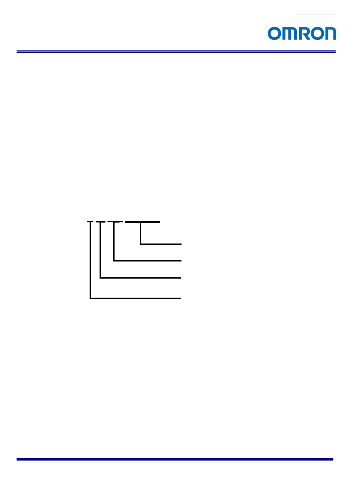
4.2 Naming Method
No.19S184-01
STC-MxS52POE
POE: PoE (Power over Ethernet (Gigabit Ethernet))
52: 1/1.7”, 0.5M Sensor
Sensor Manufacture
S: SONY
B: Monochrome
C: Color
STC-MBS52POE / STC-MCS52POE
Product Specifications and User’s Guide
10/70

No.19S184-01
5 Specifications
5.1 Electronic Specifications
Product STC-MBS52POE STC-MCS52POE
Image Sensor 1/1.7” 0.5M Progressive Monochrome CMOS
(SONY: IMX433)
Shutter Type Global Shutter
Active Picture Elements 816 (H) x 624 (V)
Cell Size 9.0 (H) x 9.0 (V) µm
Scanning Mode
Frame rate (at full scanning)
ADC bit depth 12bits
Image Output Format
Noise
Level
Sensitivity (*1) 460 Lux 900 Lux
Exposure Time
Gain Analog Gain
ROI
Gamma
Binning N/A
Decimation N/A
Image Flip
Defective Pixel Correction
Auto
Image
Control
Operational Mode
Interface PoE: IEEE802.3af CLASS2 (1000BASE-T)
Protocol GigE Vision 2.1 and GenICam SFNC 2.4, IEEE1588 (PTP)
I/O One opto-isolated input, one opto-isolated output and one open collector GPIO (Input or output)
Power Input Voltage (*2) +10.8 to +26.4 Vdc External power (via 6 pin connector) /
8bits output Less than 1.1 digits (Gain 0 dB)
10bits / 10bits Packed output
12bits / 12bits Packed output
Digital Gain
Auto Exposure
Auto Gain
Auto White Balance N/A
Consumption +12 V / +24 V: 4.1 W, PoE: 4.2 W
Mono8 / Mono10 / Mono10Packed /
Adjustable steps for size: 8 pixels in horizontal direction and 16 lines in vertical direction
Adjustable steps for offset: 8 pixels in horizontal direction and 16 lines in vertical direction
8bits: 166.5 fps / 10bits: 108.1 fps / 10bits Packed: 144.1 fps /
12bits: 108.1 fps / 12bits Packed: 144.1 fps / RGB8: 72.0 fps
Maximum frame rate: 1,432.336427 fps @ 16 lines (8bits)
Mono12 / Mono12Packed
1 µseconds to 16.777 seconds (Default: 5,890 µseconds)
Horizontal: 8 to 816 pixels, Vertical: 16 to 624 lines (Default: 816 x 624)
Full scanning (Full resolution) / ROI
Less than 4.4 digits (Gain 0 dB)
Less than 17.6 digits (Gain 0 dB)
0 to 20.8 dB (Default: 0 dB)
x1 to x3 (Default: x1)
Gamma 0.1 to 4.0 (Default: 1.0)
Horizontal / Vertical / Horizontal and Vertical / Off
Up to 2,048 points (Default: On)
Support (Default: OFF)
Support (Default: OFF)
Edge preset trigger / Pulse width trigger / Free run
Power Over Ethernet (IEEE802.3af)
Default: Bold
1/1.7” 0.5M Progressive Color CMOS
(SONY: IMX433)
Mono8 / Mono10 / Mono10Packed /
Mono12 / Mono12Packed /
BayerRG8 / BayerRG10 / BayerRG10Packed /
BayerRG12 / BayerRG12Packed / RGB8
Auto / Manual / Push to Set
STC-MBS52POE / STC-MCS52POE
Product Specifications and User’s Guide
11/70

Precautions
(*1) The sensitivity is measuring the luminance when white level achieved 100 % in below conditions.
Camera Setting Environment
Parameter Setting Parameter Setting
Gain Up 0 dB Light Source Light Box (White)
AGC Off Color temperature 5,100K
White Balance Optimum Lens
Electrical Shutter 1/30 seconds F on Lens F5.6
Black Level Optimum Target Luminance IM-600 (Topcon)
Gamma Factory Setting
(*2) The camera operates with external power when power suppling by external power supply and PoE to camera
at same time.
No.19S184-01
STC-MBS52POE / STC-MCS52POE
Product Specifications and User’s Guide
12/70
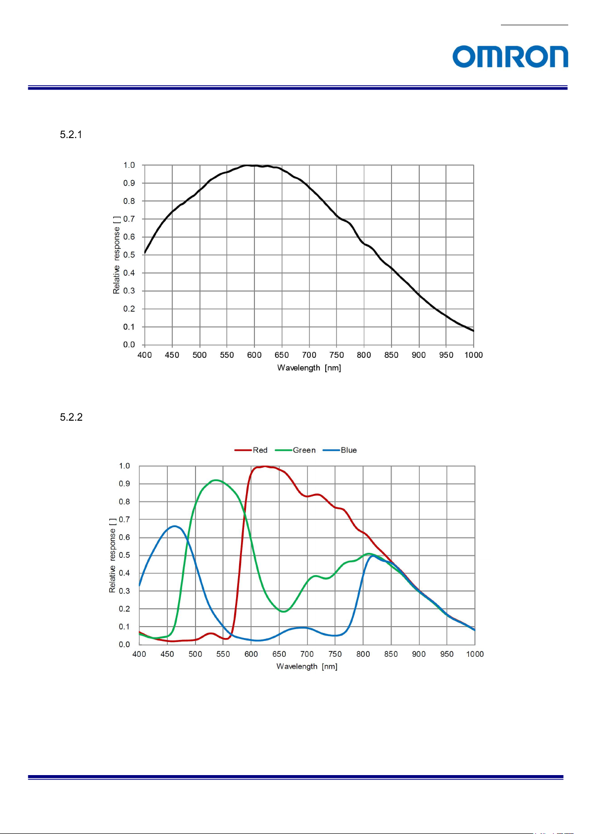
5.2 Spectral Sensitivity Characteristics
STC-MBS52POE
No.19S184-01
STC-MCS52POE (without IR Cut Filter)
STC-MBS52POE / STC-MCS52POE
Product Specifications and User’s Guide
13/70
No.19S184-01
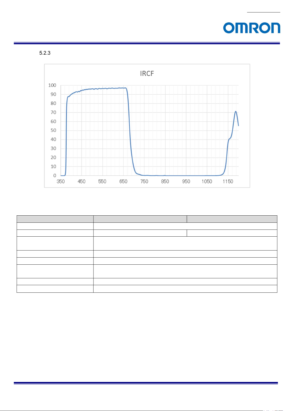
IR Cut Filter (STC-MCS52POE)
5.3 Mechanical Specifications
Model Number STC-MBS52POE STC-MCS52POE
Dimensions
Optical Filter
Optical Center Accuracy
Material
Lens Mount C mount
Interface Connectors
Camera Mounting Six M3 screw holes (Two on top, four on bottom plate)
Weight
No Optical Filter IR Cut Filter
Positional accuracy in Horizontal and Vertical directions: +/- 0.3 mm
Rotational accuracy of Horizontal and Vertical: +/- 1.5 deg.
Power- I/O connector: HR10A-7R-6PB (Hirose) or equivalent
29 (W) x 29 (H) x 53 (D) mm (*1)
Aluminum Alloy (AC)
Ethernet connector: RJ45 connector
Approximately 63 g
(*1) Excluding the connectors
STC-MBS52POE / STC-MCS52POE
Product Specifications and User’s Guide
14/70
No.19S184-01
5.4 Environmental Specifications
Model Number STC-MBS52POE STC-MCS52POE
Operational
Temperature /
Humidity
Storage Temperature / Humidity Environmental Temperature: -20 to +70 deg. C,
Vibration 20 Hz to 200 Hz to 20 Hz (5 min. / cycle), acceleration 10 G, XYZ 3 directions, 30 min. each
Shock Acceleration 38 G, half amplitude 6 ms, XYZ 3 directions, 3 times each
Standard Compliancy EMS: EN61000-6-2, EMI: EN55011
RoHS RoHS Compliance
Minimum Environmental Temperature: 0 deg. C,
Environmental Humidity: 0 to 85 %RH (No condensation)
Maximum Environmental Temperature: +36 deg. C or
Camera housing temperature (top plate) shall not exceed +63 deg. C (*1)
Environmental Humidity: 0 to 85 %RH (No condensation)
Environmental Humidity: 0 to 85 %RH (No condensation)
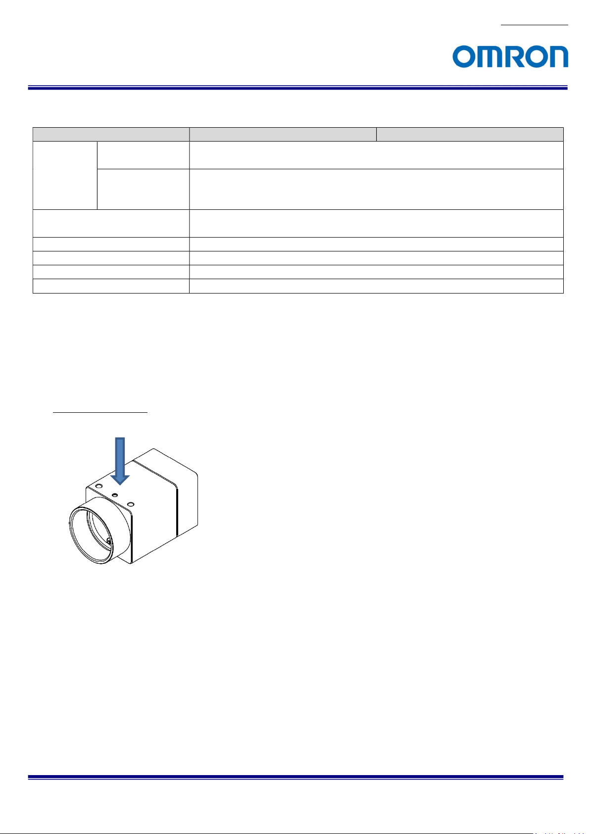
(*1) Please insure the camera is installed with the appropriate heat dissipation. If camera has a mounted lens and a tripod
with an aluminum plate, this could decrease the camera housing temperature for heat dissipation. When the internal
temperature sensor on the camera shows less than 73 deg. C, the camera housing temperature (top plate) will be less than
63 deg. C.
Taking these steps will maintain the heat rating of the electronic components of the camera.
Upper side of camera
Measuring point
STC-MBS52POE / STC-MCS52POE
Product Specifications and User’s Guide
15/70
6 Connector Specifications
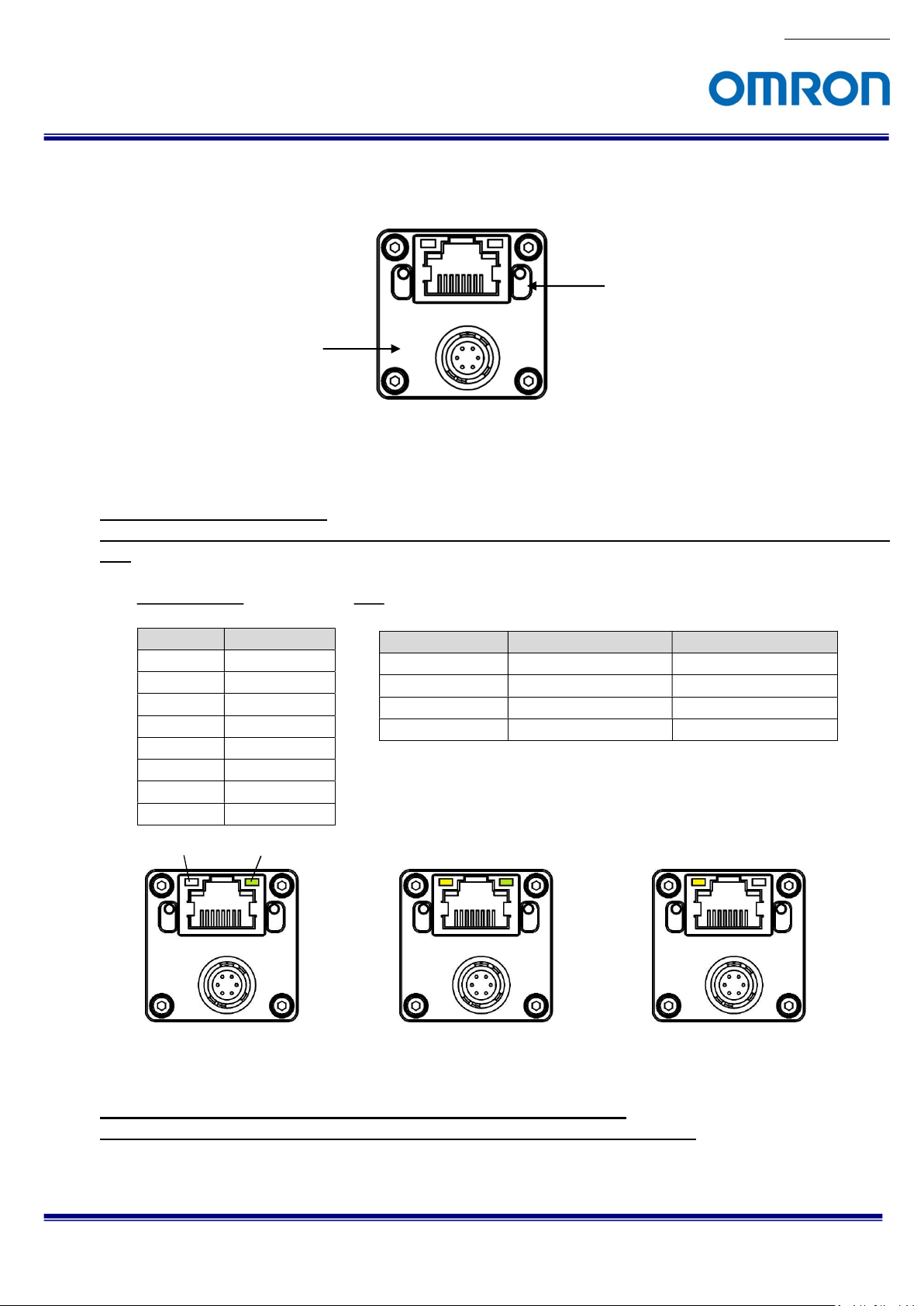
6.1 RJ45 Connector
This product is PoE compliant.
Please supply power (+10.8 to +26.4 Vdc) through the power-I/O connector when using non-PoE-compliant
NIC.
Yellow LED Green LED
Please use a 1GB supported NIC, Network Switcher and Ethernet cable.
Check the setting of NIC and Network Switcher being used is “1GB transferring”.
Power-I/O Connector
Pin Assignment LED
Pin No. Signal Name
1 TA+
2 TA3 TB+
4 TC+
5 TC6 TB7 TD+
8 TD-
Camera is powered-on
No.19S184-01
RJ45 Connector
Green LED Yellow LED Status
Green Light ON Yellow Light OFF Power ON (1GB NIC)
Green Light OFF Yellow Light OFF Power ON (100MB NIC)
Green Light ON Yellow Light Blinking 1 GB Transferring
Green Light OFF Yellow Light Blinking 100 MB Transferring
Green light: ON
Yellow light: Blinking
1 GB Transferring
Green light: OFF
Yellow light: Blinking
100 MB Transferring
STC-MBS52POE / STC-MCS52POE
Product Specifications and User’s Guide
16/70
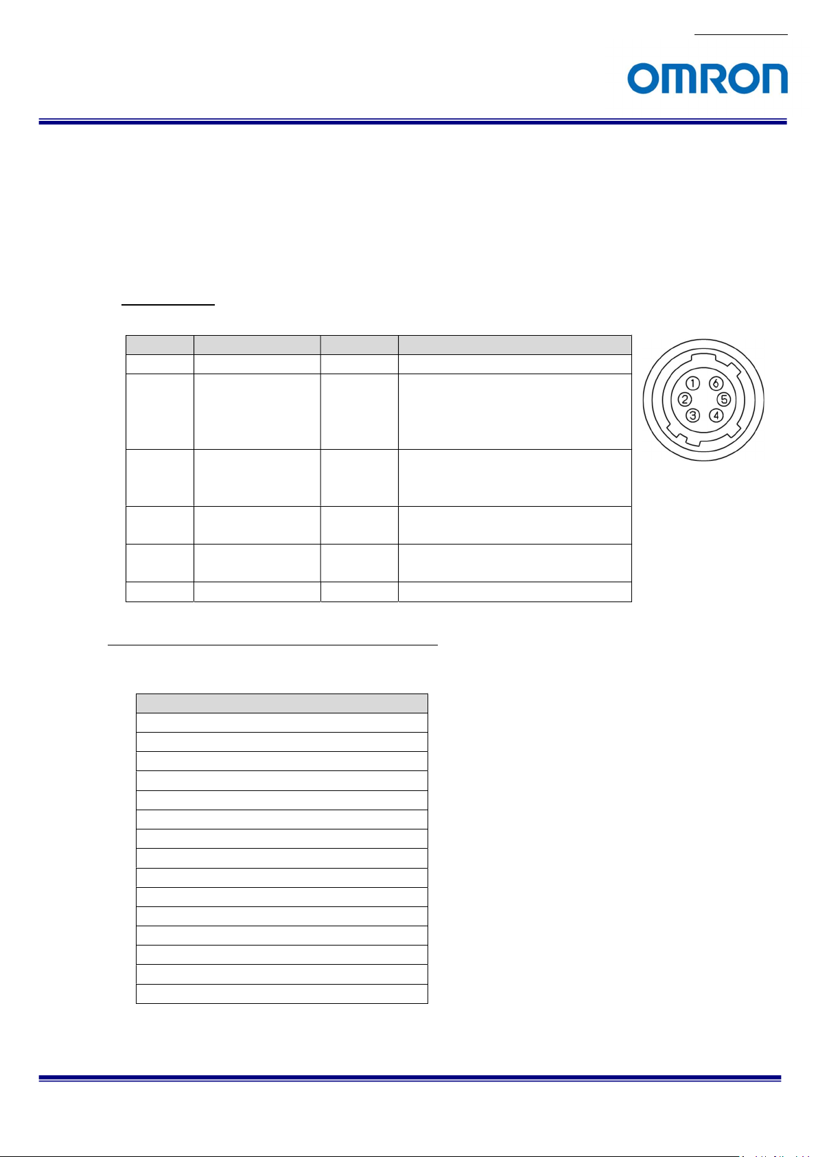
6.2 Power and Control Signal Connector
HR10A-7R-6PB (Hirose) or equivalent
This connector is for the power supply and input / output signals.
The power from this connector is priority power for camera when power supplies through this connector and
PoE at same time.
Please use HR10A-7P-6S (Hirose) or equivalent for cable.
Pin assignment
No.19S184-01
Pin No.
1 POWER IN IN +10.8 to +26.4 Vdc
2 Opto-isolated in
3 Open Collector
Configuration of Line2 (Pin No.3) and Line1 (Pin No.4)
Output signal can be assign by GenICam command.
.
4 Opto-isolated out
5 Opto-isolated
6 GND IN 0 V
1) Frame Trigger Wait (Default for all output)
2) Frame Trigger Internal
3) Exposure Active
4) Acquisition Trigger Wait
5) Acquisition Trigger Internal
6) Sensor Read Out
7) Debounced Line 0
8) Debounced Line 2
9) User Output 1
10) User Output 2
11) Timer 0 Active
12) Software Signal 0
13) Software Signal 1
14) Logic Block 0
15) Pulse Per Second
Signal Name IN / OUT
(Line0)
GPIO
(Line2)
(Line1)
Common
GenICam
Voltage
IN Low: Smaller than +1.0 V
High: +3.0 to +26.4 V
* Potential difference between
TRG_in and Opt. Isolated Common
IN / OUT
OUT Open Collector
IN
+3.0 to +26.4 V / Open Collector
STC-MBS52POE / STC-MCS52POE
Product Specifications and User’s Guide
17/70

1) Frame Trigger Wait
The condition of camera operation with trigger signal can be check.
“LOW” state of signal is out between “start exposing” to “image out”.
2) Frame Trigger Internal
The input trigger signal with the trigger delay (camera internal process delay).
3) Exposure Active
While camera exposing, “HIGH” state of signal is out. The signal state will be “LOW” after finish
exposing.
4) Acquisition Trigger Wait
While image transferring from camera to PC, “Low” state of signal is out. The signal state will be
“High” after finish image transferring.
5) Acquisition Trigger Internal
The image transferring starts signal is out.
6) Sensor Read Out
FVAL (Frame valid, HIGH state) signal is out.
7) Debounced Line0
Debounced Line0 signal is out.
8) Debounced Line2
Debounced Line2 signal is out.
9) User Output 1 (User Output signal through Line 1)
Selected “HIGH” or “LOW” state of signal is out.
10) User Output 2 (User Output signal through Line 2)
Selected “HIGH” or “LOW” state of signal is out.
11) Timer 0 Active
Selected signal at “Timer Counter” is out.
When signal synchronizing with “Exposure Active” signal, signal can use for strobe control.
12) Software Signal 0
Selected signal for “Software Signal 0” at “Software Signal Control” is out.
13) Software Signal 1
Selected signal for “Software Signal 1” at “Software Signal Control” is out.
14) Logic Block 0
“Logic Block 0” signal is out.
15) Pulse Per Second
“Pulse / second” signal (50% Duty, 1 Hz interval) is out.
STC-MBS52POE / STC-MCS52POE
Product Specifications and User’s Guide
No.19S184-01
18/70
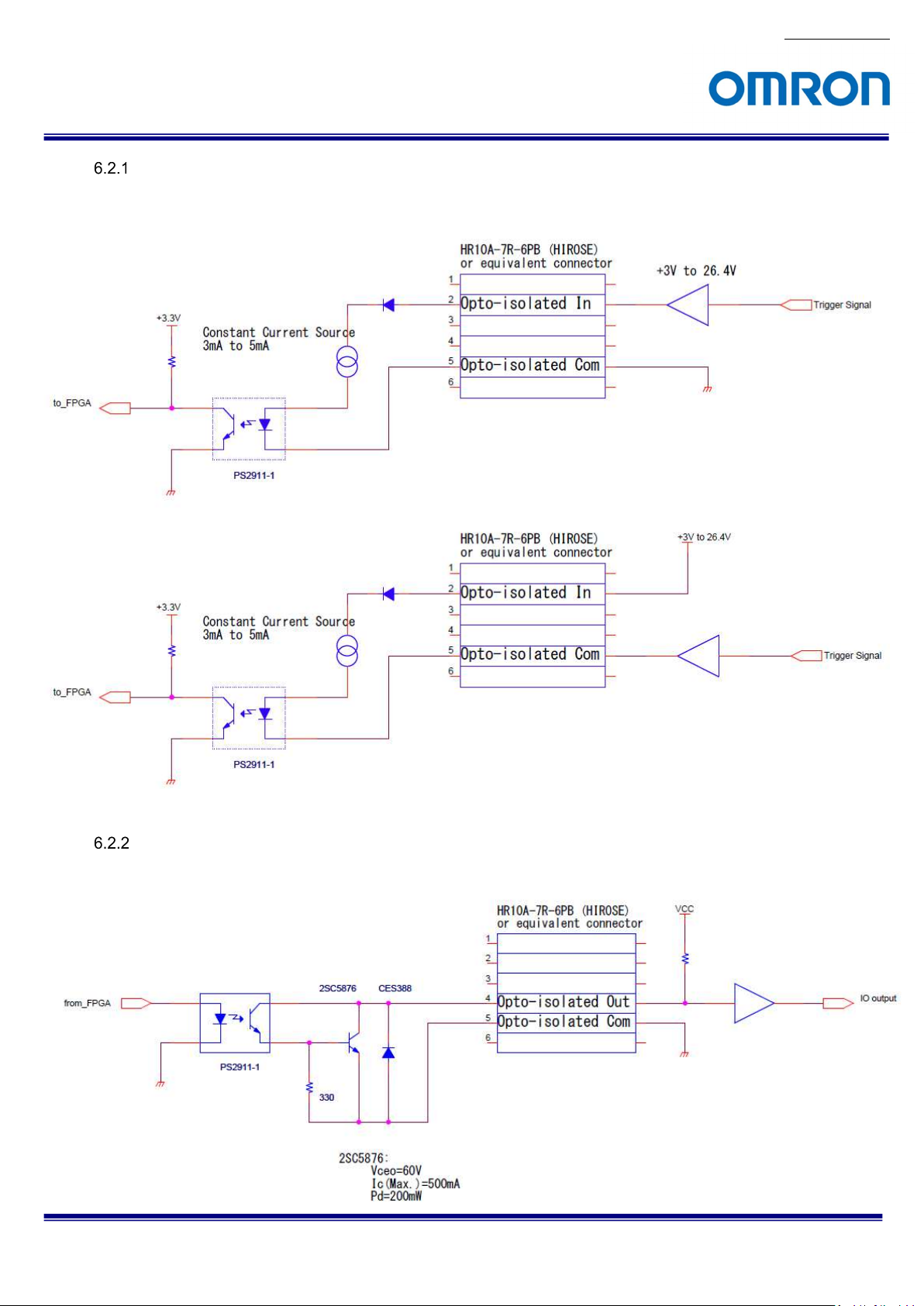
Opto-isolated input
The camera has current limiting circuit on camera. The current limiting resistor does not necessary.
Opto-isolated output
It is necessary to have current limiting resistor at outside of camera, to keep less than 50 mA.
STC-MBS52POE / STC-MCS52POE
Product Specifications and User’s Guide
No.19S184-01
19/70
No.19S184-01
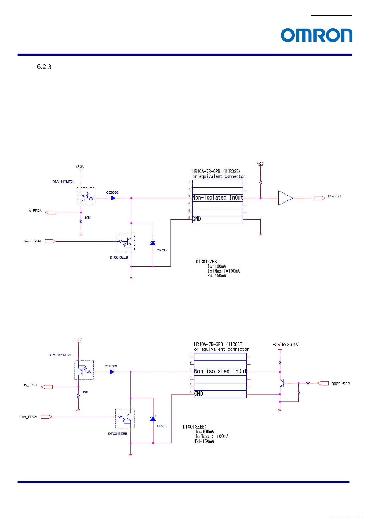
Open Collector GPIO
This GPIO can be used for input or output.
When using as output, it is necessary to have current limiting resistor at outside of camera, to keep current
less than 50 mA.
When using as input, current limiting resistor does not necessary. However, camera does not have current
limiting circuit on camera. The camera inside circuit may get damage if accidentally uses as output without
current limiting resistor. For safety, please add current limiting resistor even use as input.
a) Open Collector GPIO uses as output
b) Open Collector GIPO uses as input
STC-MBS52POE / STC-MCS52POE
Product Specifications and User’s Guide
20/70
No.19S184-01
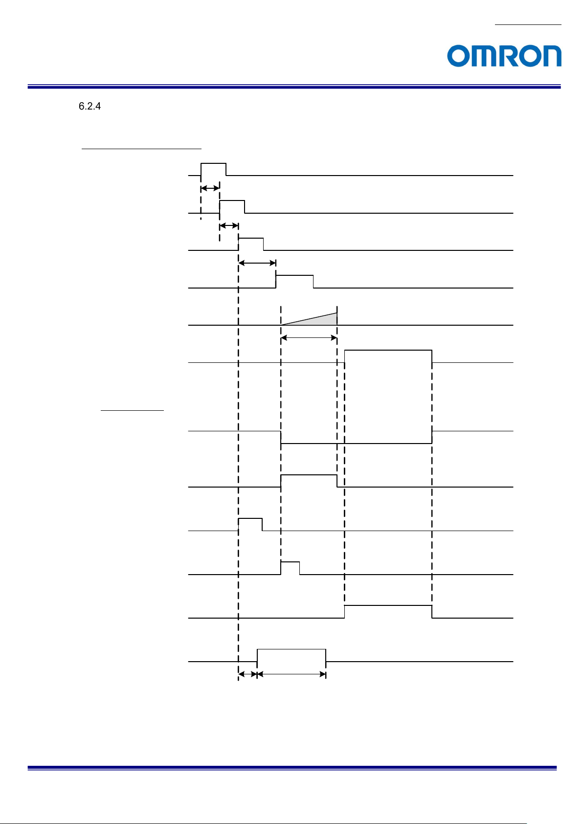
Input and Output Signal Timing (Hardware Trigger)
Case of “External Hardware Trigger”, “Timed Exposure Mode” and “Positive Edge Trigger”
Camera internal processing
External hardware
Trigger signal
Tdelay (*1)
External hardware
Trigger delay
Parameter “LineDebounceTime” on GenICam
Debounce
Parameter “TriggerDelay” on GenICam
Trigger delay
Exposure
Image out
Output signals
FrameTriggerWait
ExposureActive
DebounceLine0, 2
FramTrigg erInternal
Parameter “ExposureTime” on GenICam
SensorReadOut
(*1) Please refers “5.2.6 External Hardware Trigger Input Delay” for more details about “External hardware
STC-MBS52POE / STC-MCS52POE
Product Specifications and User’s Guide
Timer0
Parameter “TimerDelay” on GenICam Parameter “TimerDuration” on GenICam
trigger delay”
21/70
 Loading...