

Page 1
Manual No.
TOEP-C71080601-01-OY
JUNMA SERIES SERVO DRIVE
Model: SJDE-##APA-OY
USER’S MANUAL
Page 2

Copyright © 2006 YASKAWA ELECTRIC CORPORATION
All rights reserved. No part of this publication may be reproduced, stored in a retrieval system, or
transmitted, in any form, or by any means, mechanical, electronic, photocopying, recording, or
otherwise, without the prior written permission of Yaskawa. No patent liability is assumed with
respect to the use of the information contained herein. Moreover, because Yaskawa is constantly
striving to improve its high-quality products, the information contained in this manual is subject to
change without notice. Every precaution has been taken in the preparation of this manual. Nevertheless, Yaskawa assumes no responsibility for errors or omissions. Neither is any liability
assumed for damages resulting from the use of the information contained in this publication.
Page 3
Introduction
This instruction manual describes the JUNMA series AC SERVOPACKs. To properly use the JUNMA
series AC SERVOPACK, read these instructions thoroughly and retain for easy reference for inspections,
maintenance, and so on. Make sure that the end user receives this manual.
Related Manuals
Refer to the following manuals as required.
Manual Name Manual Number
JUNMA series AC SERVOMOTOR INSTRUCTIONS TOEPC23026101
Safety Information
The following conventions are used to indicate precautions in this manual. Failure to heed these precautions can result in serious or possibly even fatal injury or damage to the products or to related equipment
and systems.
WARNING
CAUTION
PROHIBITED
MANDATORY
Indicates precautions that, if not heeded, could possibly result in loss of life or
serious injury.
Indicates precautions that, if not heeded, could result in relatively serious or minor
injury, damage to the product, or faulty operation.
In some situations, the precautions indicated could have serious consequences if
not heeded.
Indicates prohibited actions that must not be performed. For example, this sym-
bol would be used as follows to indicate that fire is prohibited: .
Indicates compulsory actions that must be performed. For example, this symbol
would be used as follows to indicate that grounding is compulsory: .
2
Page 4
Notes for Safe Operation
Read these instructions thoroughly before checking products on delivery, storage and transportation,
installation, wiring, operation and inspection, and disposal of the AC SERVOPACK.
WARNING
• Be sure to correctly connect the SERVOPACK connectors, CNA and CNB.
Incorrect wiring may result in electric shock, injury, or damage to the equipment. For the
wiring method, refer to 3.8 Wiring the Power Supply/Regenerative Unit Connector (CNA)
and 3.9 Wiring the Servomotor Main Circuit Cable Connector (CNB).
• Make sure that the emergency-stop circuit turns OFF the Servo ON signal and the power
supply of the main circuit when the EMG (emergency stop) signal turns ON.
Because of residual voltage, the servomotor rotates for a few seconds after the power
supply has turned OFF. This may result in injury or damage to the equipment. Make sure
that the EMG means the stop of the motor rotation.
• Never touch any rotating motor parts while the motor is running.
Failure to observe this warning may result in injury.
• Before starting operation with a machine connected, make sure that an emergency stop
can be applied at any time. Also, design the circuit's power supply to be automatically cut
off if
/S-ON signal is OFF, and an emergency stop occurs at the same time.
Failure to observe this warning may result in injury.
• Never touch the inside of the SERVOPACKs.
Failure to observe this warning may result in electric shock.
• Do not touch terminals for five minutes after the power is turned OFF.
Residual voltage may cause electric shock.
• Follow the procedures and instructions for trial operation precisely as described in this
manual.
Malfunctions that occur after the servomotor is connected to the equipment not only damage the equipment, but may also cause an accident resulting in death or injury.
• Do not remove the front cover, cables, connectors, or optional items while the power is
ON.
Failure to observe this warning may result in electric shock.
• Installation, wiring, advice on inspection and malfunction must be performed only by
authorized personnel.
Failure to observe this warning may result in fire, electric shock, or injury.
• Do not damage, press, exert excessive force or place heavy objects on the cables or the
cables between other objects where they might be pinched.
Failure to observe this warning may result in electric shock, stopping operation of the
product, or burning.
• Provide an appropriate stopping device on the machine side to ensure safety.
A holding brake for a servomotor with brake is not a stopping device for ensuring safety.
Failure to observe this warning may result in injury.
3
Page 5
WARNING
• Do not come close to the machine immediately after resetting momentary power loss to
avoid an unexpected restart.
Take appropriate measures to ensure safety against an unexpected restart. Failure to
observe this warning may result in injury.
• Do not modify the product.
Failure to observe this warning may result in injury or damage to the product.
• Be sure to correctly ground the SERVOPACK and the servomotor.
• Connect the SERVOPACK’s ground terminal to electrical codes (ground resistance: 100 Ω
or less).
Improper grounding may result in electric shock or fire.
Checking on Delivery
WARNING
• Always use the servomotor and SERVOPACK in one of the specified combinations.
Failure to observe this caution may result in fire or malfunction.
Storage and Transportation
WARNING
• Do not store or install the product in the following places.
Failure to observe this caution may result in damage to the product.
• Locations subject to direct sunlight.
• Locations subject to temperatures outside the range specified in the storage or installation temperature conditions.
• Locations subject to humidity outside the range specified in the storage or installation
humidity conditions.
• Locations subject to condensation as the result of extreme changes in temperature.
• Locations subject to corrosive or flammable gases.
• Locations subject to dust, salts, or iron dust.
• Locations subject to exposure to water, oil, or chemicals.
• Locations subject to shock or vibration.
• Do not hold the product by the cables or motor shaft while transporting it.
Failure to observe this caution may result in injury or malfunction.
• Do not place any load exceeding the limit specified on the packing box.
Failure to observe this caution may result in injury or malfunction.
4
Page 6
Installation
• Make sure to follow the conditions on 2.1 Installation Conditions.
Failure to observe this caution may result in electric shock, fire, or SERVOPACK’s malfunction.
• Do not step on or place a heavy object on the product.
Failure to observe this caution may result in injury.
• Do not cover the inlet or outlet parts and prevent any foreign objects, such as metalic frag-
ment, or combustibles from entering the product.
Failure to observe this caution may cause internal elements to deteriorate resulting in malfunction or fire.
• Be sure to install the product in the correct direction.
Failure to observe this caution may result in malfunction.
• Provide the specified clearances between the SERVOPACK and the control panel or with
other devices.
Failure to observe this caution may result in fire or malfunction.
• SERVOPACK is precision equipment. Do not apply any strong impact.
Failure to observe this caution may result in malfunction.
Wiring
• Do not connect a three-phase power supply to the U, V, or W output terminals.
Failure to observe this caution may result in injury or fire.
• Securely connect the power supply terminals, regenerative unit connection terminal, and
motor main circuit cable terminals.
Failure to observe this caution may result in fire.
• Do not bundle or run power and signal lines together in the same duct. Keep power and
signal lines separated by at least 30 cm (11.81 in).
Failure to observe this caution may result in malfunction.
• Use twisted-pair shielded wires or multi-core twisted pair shielded wires for I/O signal
cable and encoder cable.
The maximum length is 3 m (118.11 in) for reference input lines and is 20 m (787.40 in) for
PG feedback lines.
• Do not touch the power terminals for five minutes after turning the power supply LED
(PWR) are OFF because high voltage may still remain in the SERVOPACK.
Make sure the charge indicator is turned OFF first before starting an inspection.
• Avoid frequently turning power ON and OFF. Do not turn power ON or OFF more than once
per minute.
Since the SERVOPACK has a capacitor in the power supply, a high charging current flows
for 0.2 seconds when power is turned ON. Frequently turning power ON and OFF causes
main power devices such as capacitors and fuses to deteriorate, resulting in unexpected
problems.
WARNING
WARNING
5
Page 7
WARNING
• Observe the following precautions when wiring connector for power supply/regenerative
unit.
• Remove the connector for power supply/regenerative unit from the SERVOPACK prior to
wiring.
• Insert only one wire per terminal on the connector for power supply/regenerative unit.
• Make sure that the core wire is not electrically shorted to adjacent core wires.
• Be sure to wire correctly and securely.
Failure to observe this caution may result in motor overrun, injury, or malfunction.
• Always use the specified power supply voltage of single-phase 200 V to 230 V without
connecting directly to a voltage of 400 V.
The SERVOPACK will be destroyed.
• Take appropriate measures to ensure that the input power supply is supplied within the
specified voltage fluctuation range. Be particularly careful in places where the power supply is unstable.
An incorrect power supply may result in damage to the product.
• Install external breakers or other safety devices against short-circuiting in external wiring.
Failure to observe this caution may result in fire.
• Take appropriate and sufficient countermeasures for each when installing systems in the
following locations.
Failure to observe this caution may result in damage to the product.
• Locations subject to static electricity or other forms of noise.
• Locations subject to strong electromagnetic fields and magnetic fields.
• Locations subject to possible exposure to radioactivity.
• Locations close to power supplies including power supply lines.
• Do not reverse the polarity of the battery when wiring with regenerative unit.
Failure to observe this caution may result in damage to the product.
6
Page 8
Operation
WARNING
• Conduct trial operation on the servomotor alone with the motor shaft disconnected from
machine to avoid any unexpected accidents.
Failure to observe this caution may result in injury.
• Before starting any operation with a machine connected, change the settings of the SERVOPACK’s reference pulse with the PULSE rotary switch to match those of the machine.
Starting operation without matching the proper settings may cause the machine to run out
of control or malfunction.
• When using the servomotor for a vertical axis, install safety devices to prevent workpieces
from falling off because of alarms.
Workpiece’s falling off may result in injury or malfunction.
• Do not touch the SERVOPACK heatsinks, regenerative unit, or servomotor while power is
ON or soon after the power is turned OFF.
Failure to observe this caution may result in burns due to high temperatures.
• When an alarm occurs, remove the cause, turn OFF the power and ON again after confirming safety, and then resume operation.
Failure to observe this caution may result in injury.
• Do not use the holding brake of the servomotor for ordinary braking.
Failure to observe this caution may result in malfunction.
Maintenance and Inspection
WARNING
• Do not open the SERVOPACK case for 5 minutes after the power supply lamp (PWR LED)
goes out. High voltage may remain in the SERVOPACK after the power supply has been
turned OFF.
• After turning OFF the power supply, wait 15 minutes before replacing the cooling fan.
Failure to observe this caution may result in burns because the cooling fan is hot.
• Mount the cooling fan in the correct way explained in 6.3 Replacement of Cooling Fan.
Mounting the cooling fan in the incorrect direction may result in the breakdown of the SERVOPACK.
• Do not attempt to change wiring while the power is ON.
Failure to observe this caution may result in electric shock or injury.
Disposal
WARNING
• When disposing of the products, treat them as general industrial waste.
7
Page 9

General Precautions
Note the following to ensure safe application.
• The drawings presented in this manual are sometimes shown without covers or protective guards.
Always replace the cover or protective guard as specified first, and then operate the products in
accordance with the manual.
• The drawings presented in this manual are typical examples and may not match the product you
received.
• This manual is subject to change due to product improvement, specification modification, and
manual improvement. When this manual is revised, the manual code is updated and the new
manual is published as a next edition.
• If the manual must be ordered due to loss or damage, inform your nearest representative of
OMRON YASKAWA Motion Control B.V. (OYMC) or one of the offices listed on the back of this
manual.
• OYMC will not take responsibility for the results of unauthorized modifications of this product.
OYMC shall not be liable for any damages or troubles resulting from unauthorized modification.
8
Page 10

CONTENTS
Introduction . . . . . . . . . . . . . . . . . . . . . . . . . . . . . . . . . . . . . . . . . . . . . . . . . 2
Related Manuals . . . . . . . . . . . . . . . . . . . . . . . . . . . . . . . . . . . . . . . . . . . . . 2
Safety Information . . . . . . . . . . . . . . . . . . . . . . . . . . . . . . . . . . . . . . . . . . . . 2
Notes for Safe Operation . . . . . . . . . . . . . . . . . . . . . . . . . . . . . . . . . . . . . . 3
1 BEFORE USE . . . . . . . . . . . . . . . . . . . . . . . . . . . . . . . . . . . . . . . . . . . . 11
1.1 Warning Label . . . . . . . . . . . . . . . . . . . . . . . . . . . . . . . . . . . . . . . . . . . . . . . . . . . . . 11
1.2 Checking Products . . . . . . . . . . . . . . . . . . . . . . . . . . . . . . . . . . . . . . . . . . . . . . . . . 11
1.3 Model Designation . . . . . . . . . . . . . . . . . . . . . . . . . . . . . . . . . . . . . . . . . . . . . . . . . . 12
1.4 SERVOPACKs and Applicable Servomotors . . . . . . . . . . . . . . . . . . . . . . . . . . . . . . 12
1.5 Part Names and Functions . . . . . . . . . . . . . . . . . . . . . . . . . . . . . . . . . . . . . . . . . . . 13
Reference Pulse Setting (PULSE) . . . . . . . . . . . . . . . . . . . . . . . . . . . . . . . . . . . . 13
Reference Filter Setting Rotary Switch (FIL) . . . . . . . . . . . . . . . . . . . . . . . . . . . . 14
Reference Display (REF) . . . . . . . . . . . . . . . . . . . . . . . . . . . . . . . . . . . . . . . . . . . 14
Alarm Display (AL1, AL2, and AL3) . . . . . . . . . . . . . . . . . . . . . . . . . . . . . . . . . . . 14
2 INSTALLATION . . . . . . . . . . . . . . . . . . . . . . . . . . . . . . . . . . . . . . . . . . . 15
2.1 Installation Conditions . . . . . . . . . . . . . . . . . . . . . . . . . . . . . . . . . . . . . . . . . . . . . . . 15
2.2 Installation Method . . . . . . . . . . . . . . . . . . . . . . . . . . . . . . . . . . . . . . . . . . . . . . . . . 16
Installation Method and Direction . . . . . . . . . . . . . . . . . . . . . . . . . . . . . . . . . . . . 16
Space between SERVOPACK Units . . . . . . . . . . . . . . . . . . . . . . . . . . . . . . . . . . 16
3 WIRING . . . . . . . . . . . . . . . . . . . . . . . . . . . . . . . . . . . . . . . . . . . . . . . . . 17
3.1 Precautions on Wiring . . . . . . . . . . . . . . . . . . . . . . . . . . . . . . . . . . . . . . . . . . . . . . . 17
Protection for Power Supply Line . . . . . . . . . . . . . . . . . . . . . . . . . . . . . . . . . . . . 17
Caution for Grounding . . . . . . . . . . . . . . . . . . . . . . . . . . . . . . . . . . . . . . . . . . . . . 17
Caution for Cable . . . . . . . . . . . . . . . . . . . . . . . . . . . . . . . . . . . . . . . . . . . . . . . . 17
Other Precautions . . . . . . . . . . . . . . . . . . . . . . . . . . . . . . . . . . . . . . . . . . . . . . . . 18
Power Loss . . . . . . . . . . . . . . . . . . . . . . . . . . . . . . . . . . . . . . . . . . . . . . . . . . . . . 18
Molded-Case Circuit Breaker (MCCB) or Fuse Capacity Relation to Power-Supply
Capacity . . . . . . . . . . . . . . . . . . . . . . . . . . . . . . . . . . . . . . . . . . . . . . . . . . . . . . . 19
Noise Prevention . . . . . . . . . . . . . . . . . . . . . . . . . . . . . . . . . . . . . . . . . . . . . . . . . 20
3.2 System Configuration . . . . . . . . . . . . . . . . . . . . . . . . . . . . . . . . . . . . . . . . . . . . . . . 23
3.3 Standard Connection . . . . . . . . . . . . . . . . . . . . . . . . . . . . . . . . . . . . . . . . . . . . . . . . 24
3.4 Installation and Wiring Conditions on CE Marking . . . . . . . . . . . . . . . . . . . . . . . . . 25
Attaching the Ferrite Core . . . . . . . . . . . . . . . . . . . . . . . . . . . . . . . . . . . . . . . . . . 26
Fixing the Cable . . . . . . . . . . . . . . . . . . . . . . . . . . . . . . . . . . . . . . . . . . . . . . . . . 26
Shield Box . . . . . . . . . . . . . . . . . . . . . . . . . . . . . . . . . . . . . . . . . . . . . . . . . . . . . . 26
3.5 SERVOPACKs and Applicable Peripheral Devices . . . . . . . . . . . . . . . . . . . . . . . . . 27
3.6 Main Circuit Wiring . . . . . . . . . . . . . . . . . . . . . . . . . . . . . . . . . . . . . . . . . . . . . . . . . 27
9
Page 11

3.7 SERVOPACK Main Circuit Wire Size . . . . . . . . . . . . . . . . . . . . . . . . . . . . . . . . . . . . 28
Cable Types . . . . . . . . . . . . . . . . . . . . . . . . . . . . . . . . . . . . . . . . . . . . . . . . . . . . . 28
Wire Size and Allowable Current . . . . . . . . . . . . . . . . . . . . . . . . . . . . . . . . . . . . . 28
Power Supply Input Terminals (L1, L2), Motor Connection Terminals (U, V, W),
and Regenerative Unit Connection Terminals (+, -) 28
Ground Terminal () . . . . . . . . . . . . . . . . . . . . . . . . . . . . . . . . . . . . . . . . . . . . . . . . 28
Encoder signal connector . . . . . . . . . . . . . . . . . . . . . . . . . . . . . . . . . . . . . . . . . . 29
I/O signal connector . . . . . . . . . . . . . . . . . . . . . . . . . . . . . . . . . . . . . . . . . . . . . . 29
3.8 Wiring the Power Supply/Regenerative Unit Connector (CNA) . . . . . . . . . . . . . . . . 30
Wire Size . . . . . . . . . . . . . . . . . . . . . . . . . . . . . . . . . . . . . . . . . . . . . . . . . . . . . . . 30
Connector for Power Supply/Regenerative Unit (CNA) . . . . . . . . . . . . . . . . . . . . 31
3.9 Wiring the Servomotor Main Circuit Cable Connector (CNB) . . . . . . . . . . . . . . . . . 32
Servomotors without Brakes . . . . . . . . . . . . . . . . . . . . . . . . . . . . . . . . . . . . . . . . 32
Servomotors with Brakes . . . . . . . . . . . . . . . . . . . . . . . . . . . . . . . . . . . . . . . . . . 33
3.10 Wiring the Encoder Connector (CN2) . . . . . . . . . . . . . . . . . . . . . . . . . . . . . . . . . . 35
Connection Diagram for Standard Encoder Cable . . . . . . . . . . . . . . . . . . . . . . . 35
3.11 Wiring I/O Connectors . . . . . . . . . . . . . . . . . . . . . . . . . . . . . . . . . . . . . . . . . . . . . . 36
Connection Diagram for Standard I/O Cable
(supplied by Yaskawa Electric Company . . . . . . . . . . . . . . . . . . . . . . . . . . . . . . 36
Connection Diagram and Description for the General-purpose control cables
(R7A-CPZ@@@S) supplied by OMRON Company. . . . . . . . . . . . . . . . . . . . . . . . 37
3.12 Connection Examples of Input Signal . . . . . . . . . . . . . . . . . . . . . . . . . . . . . . . . . . 39
Line Driver Output . . . . . . . . . . . . . . . . . . . . . . . . . . . . . . . . . . . . . . . . . . . . . . . . 39
Open-collector Output . . . . . . . . . . . . . . . . . . . . . . . . . . . . . . . . . . . . . . . . . . . . 39
3.13 Connection Example of Output Signal . . . . . . . . . . . . . . . . . . . . . . . . . . . . . . . . . 40
3.14 EMG Sequence . . . . . . . . . . . . . . . . . . . . . . . . . . . . . . . . . . . . . . . . . . . . . . . . . . . 41
3.15 Explanation of I/O Signals . . . . . . . . . . . . . . . . . . . . . . . . . . . . . . . . . . . . . . . . . . . 42
4 TRIAL OPERATION . . . . . . . . . . . . . . . . . . . . . . . . . . . . . . . . . . . . . . . . . 44
5 TROUBLESHOOTING . . . . . . . . . . . . . . . . . . . . . . . . . . . . . . . . . . . . . . . 46
5.1 Alarm Indicator Lights . . . . . . . . . . . . . . . . . . . . . . . . . . . . . . . . . . . . . . . . . . . . . . . 46
5.2 Troubleshooting for Malfunctions when Alarm Indicators Are Not Lit . . . . . . . . . . . 51
6 INSPECTIONS . . . . . . . . . . . . . . . . . . . . . . . . . . . . . . . . . . . . . . . . . . . . 54
6.1 Regular Inspections . . . . . . . . . . . . . . . . . . . . . . . . . . . . . . . . . . . . . . . . . . . . . . . . . 54
6.2 Part's Life Expectancy . . . . . . . . . . . . . . . . . . . . . . . . . . . . . . . . . . . . . . . . . . . . . . . 54
6.3 Replacement of Cooling Fan . . . . . . . . . . . . . . . . . . . . . . . . . . . . . . . . . . . . . . . . . . 55
7 SPECIFICATIONS . . . . . . . . . . . . . . . . . . . . . . . . . . . . . . . . . . . . . . . . . . 60
7.1 Specifications . . . . . . . . . . . . . . . . . . . . . . . . . . . . . . . . . . . . . . . . . . . . . . . . . . . . . 60
7.2 Overload Protection Characteristics . . . . . . . . . . . . . . . . . . . . . . . . . . . . . . . . . . . . 61
10
Page 12
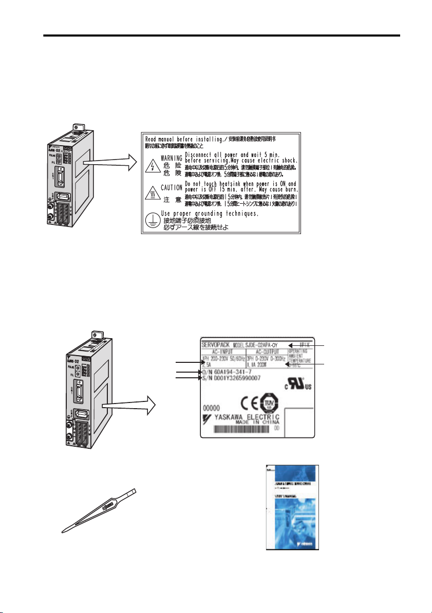
1.1 Warning Label
1 Before Use
1.1 Warning Label
A warning label is located on the side of the SERVOPACK.
SERVOPACK's Warning Label
1.2 Checking Products
Confirm that the following items have been delivered together with the SERVOPACK. Verify that the
ordered product as received by the model number marked on the nameplate on the SERVOPACK.
If you find any irregularities such as incorrect SERVOPACK model, damages, and missing parts or items,
contact your OYMC representative or the dealer from whom you purchased the products.
SJDE
SERVOPACK
OMRON
A
9
8
7
A
9
8
7
D
C
B
6
5
4
D
C
B
6
5
4
APA-OY
R
E
F
0
1
2
3
E
F
0
1
2
3
E
F
Applicable
power supply
Order number
Serial number
Nameplate
SERVOPACK
model
Applicable motor
capacity
One screwdriver for selecting
the pulse and setting the filter
Connector Part Number JZSP-CHG9-1
One copy of this
Instruction Manual
11
Page 13
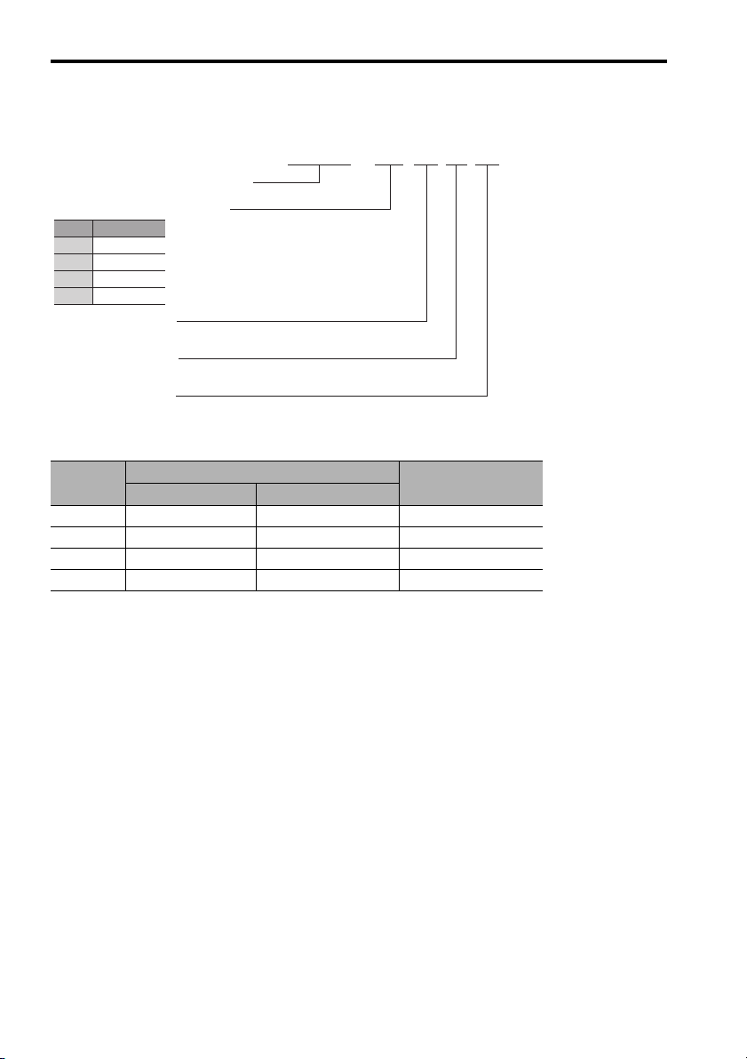
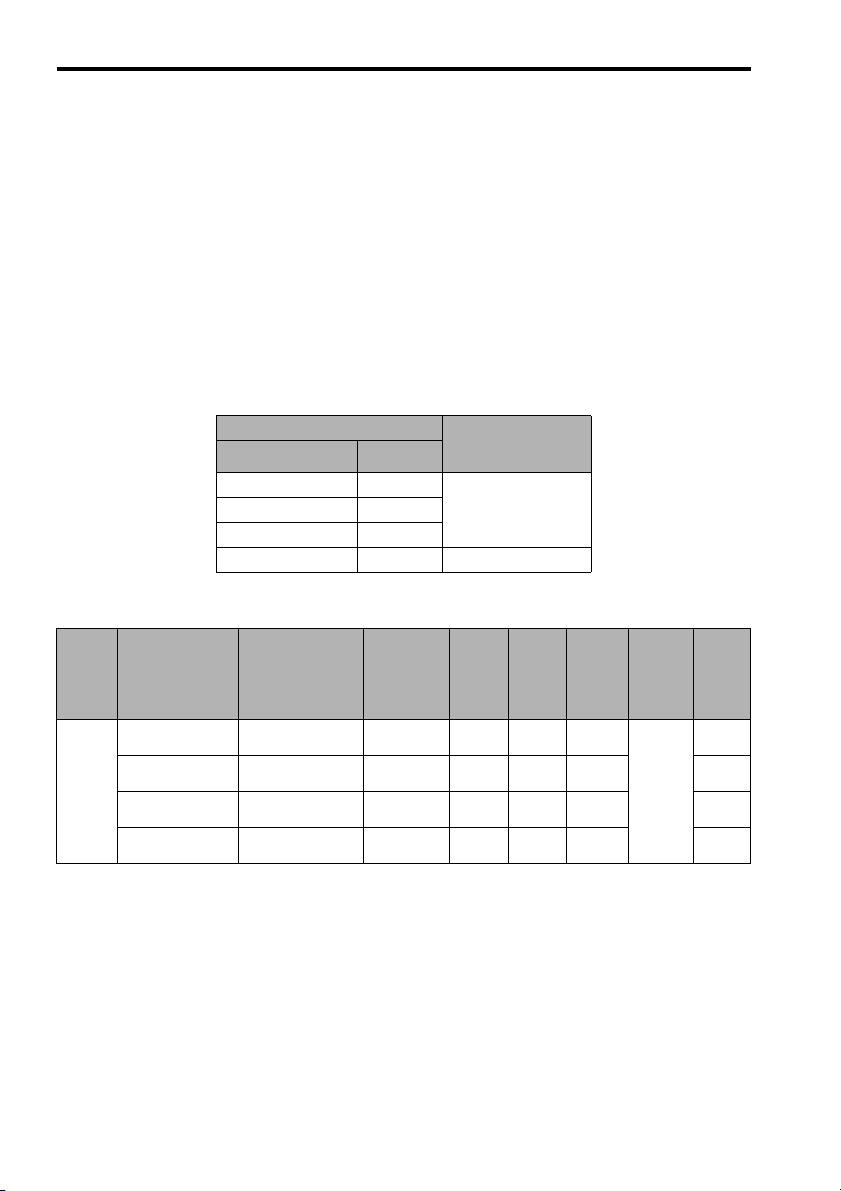
1.3 Model Designation
A
A
A
1.3 Model Designation
SJDE—02 A P A —OY
JUNMA series SERVOPACK SJDE
pplicable servomotor capacity
Code
Output (W)
100
01
200
02
400
04
750
08
Power supply voltage
: 200 VAC
Interface specification
P: Pulse train reference
Design revision order
1.4 SERVOPACKs and Applicable Servomotors
Rated
Output
100W SJME-01AMB41-OY SJME-01AMB4C-OY SJDE-01APA-OY
200W SJME-02AMB41-OY SJME-02AMB4C-OY SJDE-02APA-OY
400W SJME-04AMB41-OY SJME-04AMB4C-OY SJDE-04APA-OY
750W SJME-08AMB41-OY SJME-08AMB4C-OY SJDE-08APA-OY
Without Brakes With Brakes
Servomotor SERVOPACK
12
Page 14
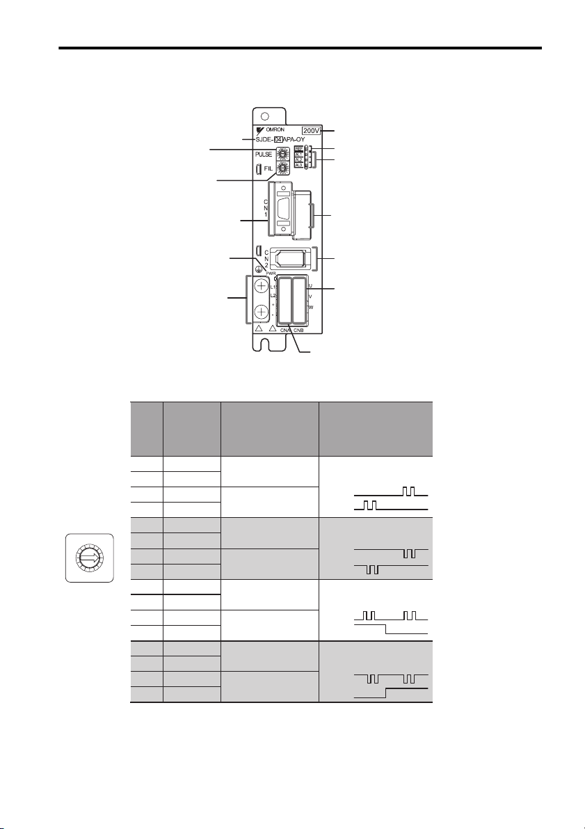
1.5 Part Names and Functions
1.5 Part Names and Functions
Rotary switch for reference
pulse setting (PULSE)
Rotary switch for reference
filter setting (FIL)
I/O signal connector (CN1)
Power supply indicator
(PWR)
Ground terminal
Ty pe
Reference Pulse Setting (PULSE)
Reference
Set
0
1
2
3
4
5
6
7
8
9
A
B
C
D
E
F
Pulse
Resolution
(P/REV)
1000
2500
5000
10000
1000
2500
5000
10000
1000
2500
5000
10000
1000
2500
5000
10000
Value
PULSE
D
C
B
E
A
F
9
0
8
1
7
2
6
3
5
4
Note: 1. Make settings after turning OFF the power.
2. The factory setting is 0.
Reference Pulse
Connection Method
Open collector
or line driver
Line driver
Open collector
or line driver
Line driver
Open collector
or line driver
Line driver
Open collector
or line driver
Line driver
Input voltage
Reference indicator (REF)
Alarm indicators (AL1 to AL3)
This connector is for factory use only.
(Do not use!)
Encoder connector (CN2)
Connector for motor main
circuit cable (CNB)
Connector for power supply /
regenerative unit (CNA)
Reference
Pulse Type
CW + CCW
Positive logic
CW
CCW
CW + CCW
Negative logic
CW
CCW
Mark + pulse sequence,
Positive logic
PULS
SIGN
Mark + pulse sequence,
Negative logic
PULS
SIGN
13
Page 15
1.5 Part Names and Functions
A
A
A
A
A
A
A
A
A
A
A
A
A
A
A
A
A
A
A
A
A
A
A
A
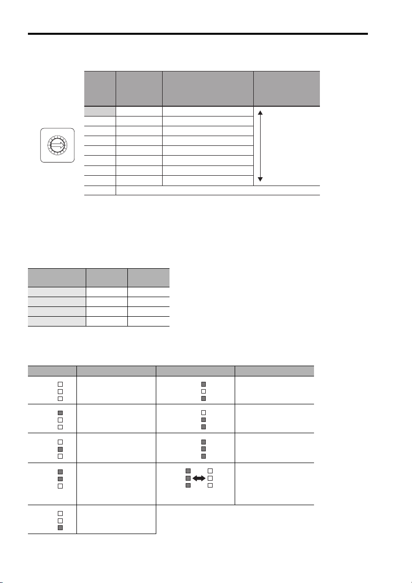
Reference Filter Setting Rotary Switch (FIL)
Acceleration/
Filter
Deceleration
Time for Step
2
Reference
1
0*
1
2
3
4
5
6
7
Do not set 8 through F.
8 to F
45 ms
50 ms
60 ms
65 ms
70 ms
80 ms
85 ms
170 ms
FIL
A
9
8
7
Setting
Value*
D
C
B
E
F
0
1
2
6
3
5
4
* 1. The factory setting is 0. If the machine vibrates, this value must be changed.
* 2. If the machine vibrates when starting or stopping the machine, set a larger value.
* 3. The value depends on conditions such as the level of command acceleration and
deceleration, the machine rigidity and the motor resolution (PULSE switch).
* 4. Select the correct servomotor capacity with these values if using a step reference
that has no acceleration or deceleration time.
Approx. Time between
Completing Reference and
Completing Positioning
*4
(Settling Time)*
100 to 200 ms
110 to 220 ms
130 to 260 ms
150 to 300 ms
170 to 340 ms
200 to 400 ms
250 to 500 ms
500 to 1000 ms
Description
3
Small filter time
constant (short
positioning time)
Large filter time
constant
(little vibration
with a long
positioning time)
Reference Display (REF)
Indicators* Motor
Power
Lit orange. OFF −
Blinks orange. OFF Input
Lit green. ON −
Blinks green. ON Input
* Lit yellow for 1s when the clear signal is input.
Reference
Pulses
Alarm Display (AL1, AL2, and AL3)
Indicators Meaning of Alarm Indicators Meaning of Alarm
L1
L2
L3
L1
L2
L3
L1
L2
L3
L1
L2
L3
L1
L2
L3
Normal Overcurrent
Speed error
Overload System error
Encoder error
L1
L2
L3
L1
L2
L3
L1
L2
L3
AL1
AL2
AL3
Blinks at regular
intervals.
SERVOPACK’s built-in
fan stop
Rotary switch for
reference pulse setting
(PULSE) changed.
Voltage error
14
Page 16
2.1 Installation Conditions
2 Installation
The following shows the installation location and method of the SERVOPACK.
2.1 Installation Conditions
Item Specifications
Operating temperature 0 ° C to +55 °C
Operating humidity 90% RH or less (with no condensation)
Storage temperature -20 ° C to +70 ° C
Storage humidity 90% RH or less (with no condensation)
Installation site Free of corrosive gases
Altitude 1000 m or below
Vibration resistance
Shock resistance
Operating conditions Installation category (overvoltage category): II
Installation in a control
panel
Installation near a
heating unit
Installation
Site
Installation near a
source of vibration
Installation at a site
exposed to corrosive
gas
Free of dust and iron powder
Clean and dry
2
4.9m/s
2
19.6m/s
Pollution degree: 2
Protection class: IP10 (EN50178)
Design the control panel size, unit layout, and cooling method so
the temperature around the SERVOPACK does not exceed 55 ° C.
Minimize the heat radiating from the heating unit as well as any
temperature rise caused by natural convection so the temperature
around the SERVOPACK does not exceed 55 ° C.
Install a vibration isolator beneath the SERVOPACK to avoid subjecting
it to vibration.
Corrosive gas does not have an immediate effect on the SERVOPACK
but will eventually cause the electronic components and contactor-
related devices to malfunction. Take appropriate action to avoid corrosive gas.
15
Page 17
2.2 Installation Method
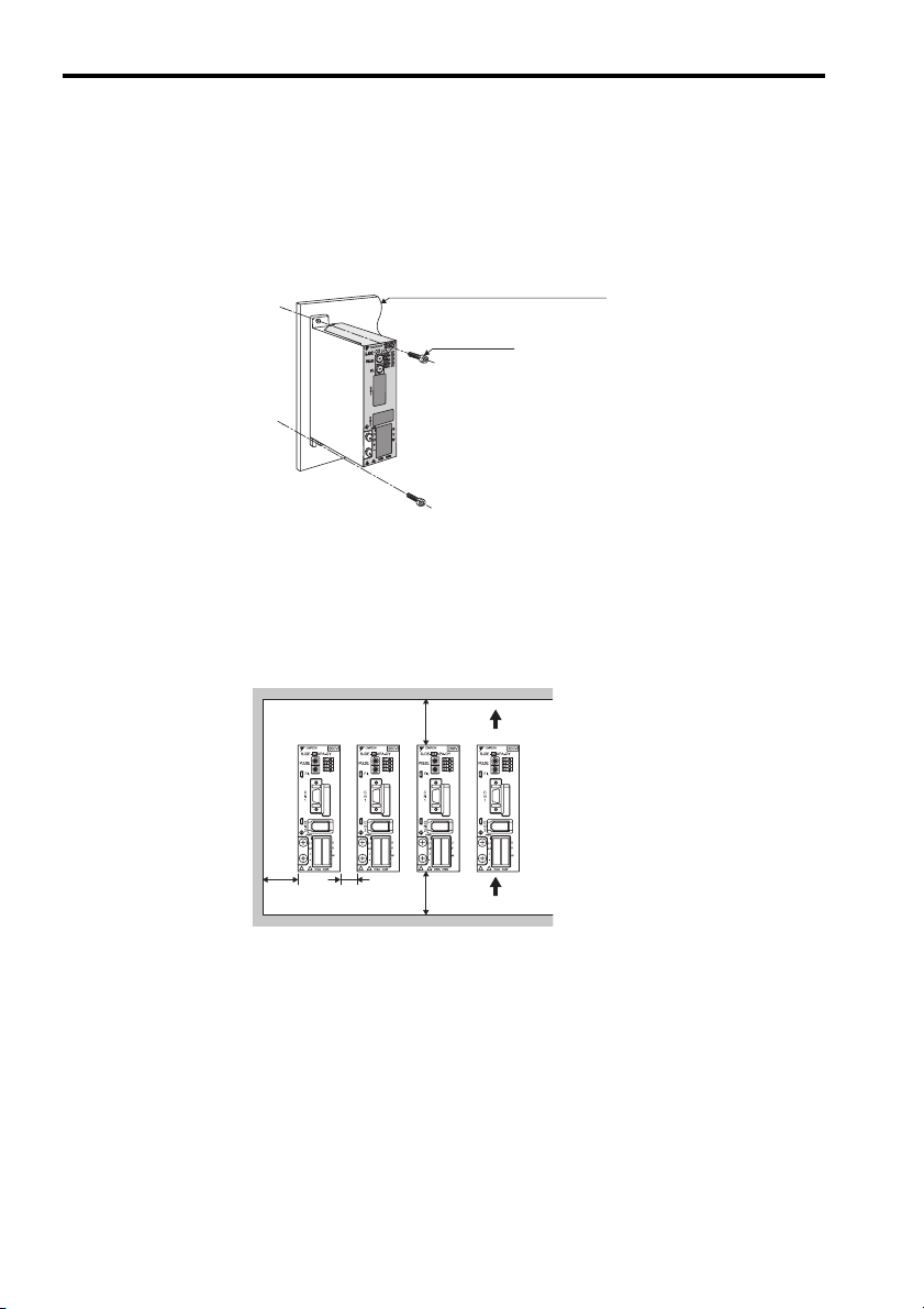
2.2 Installation Method
Installation Method and Direction
• Install the SERVOPACK perpendicular to the wall. The SERVOPACK contains a built-in fan for cooling
and must be mounted in the specified direction.
• Connect the mounting holes securely to the mounting surface with M4 screws (two mounting holes).
SERVOPACK installation plate
M4 screw
Space between SERVOPACK Units
• Be sure to keep a space between adjacent SERVOPACK units if they are mounted inside the control
panel so that the units can be cooled.
• Do not cover the inlet or outlet parts and prevent any foreign objects, such as metalic fragment, or
combustibles from entering the product.
Failure to observe this caution may cause internal elements to deteriorate resulting in malfunction or
fire.
30 mm
min.
10 mm
min.
50 mm
min.
50 mm
min.
16
Air outlet direction
Air inlet direction
Page 18
3.1 Precautions on Wiring
3 Wiring
3.1 Precautions on Wiring
WARNING
• Be sure to correctly ground the SERVOPACK and the servomotor.
• Wiring must be performed by an authorized person qualified in electrical work.
Protection for Power Supply Line
• Use a molded-case circuit breaker and fuse to protect the power supply line from high voltage. The
SJDE SERVOPACK connects directly to a commercial power supply without a transformer, so always
use a circuit breaker and fuse to protect the SERVOPACK from accidental high voltage.
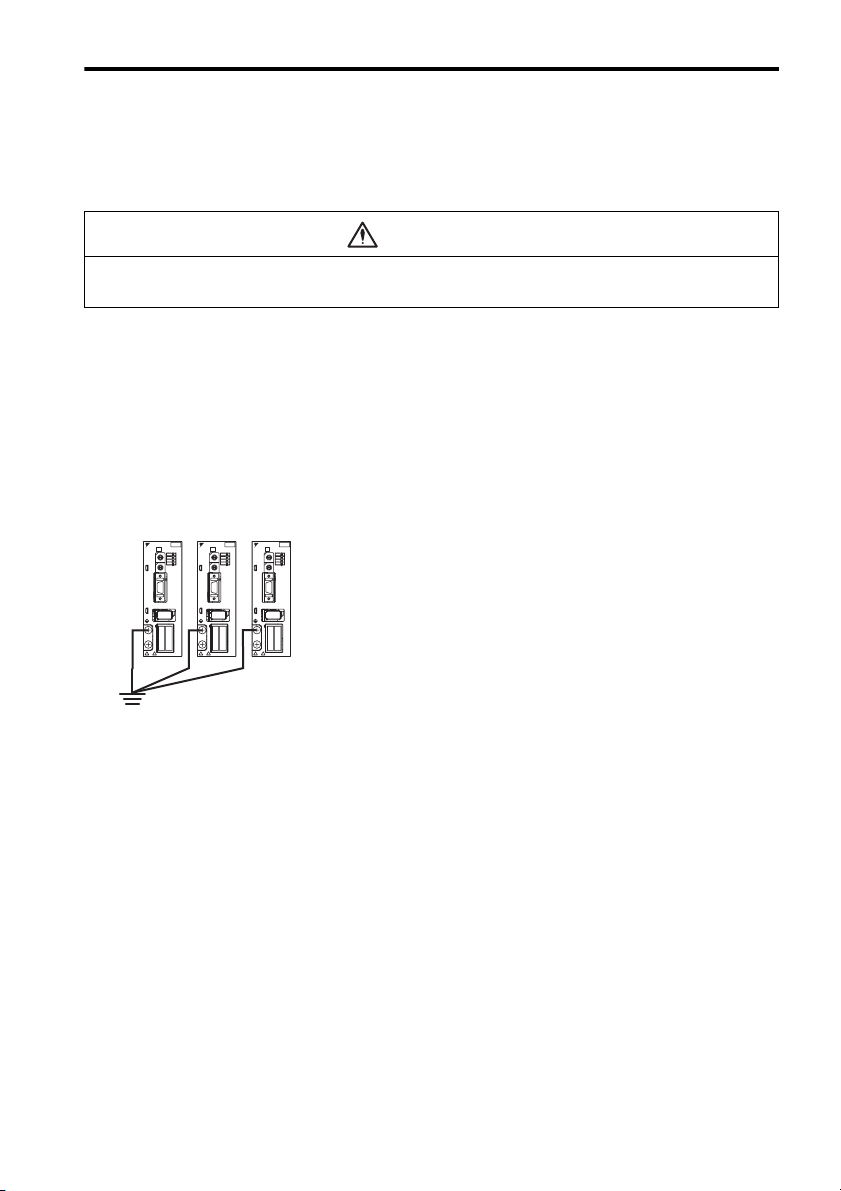
Caution for Grounding
Consider the following conditions when grounding the SERVOPACK.
• For a ground wire, use as thick a cable as possible (2.0 mm2 or thicker).
• A ground resistance of 100 (Ω) or less is recommended.
• Ground to one point only.
OMRON
SJDE- 04 APA-OY
9
PULSE
9
FIL
C
N
1
C
N
2
PWR
L1
L2
+
-
OMRON
OMRON
200V
200V
SJDE- 04 APA-OY
C
C
D
D
B
B
E
E
CTL
A
A
F
F
9
0
0
8
8
1
1
AL1
PULSE
7
7
2
2
6
6
3
3
4
4
5
5
AL2
C
C
AL3
D
D
B
B
E
E
A
A
F
F
9
0
0
8
8
1
1
FIL
7
7
2
2
6
6
3
3
4
4
5
5
C
N
1
C
N
2
PWR
U
L1
V
L2
+
W
-
CNA CNB
CNA CNB
200V
SJDE- 04 APA-OY
C
D
B
E
CTL
CTL
A
F
9
0
8
1
AL1
AL1
PULSE
7
2
6
3
4
5
AL2
AL2
C
AL3
AL3
D
B
E
A
F
9
0
8
1
FIL
7
2
6
3
4
5
C
N
1
C
N
2
PWR
U
U
L1
V
V
L2
+
W
W
-
CNA CNB
Caution for Cable
• For wiring, use the specified cables. Use cables that are as short as possible.
• Do not bend or apply tension to cables. The conductor of a signal cable is very thin (0.08 to
0.12 mm2), so handle the cables carefully.
17
Page 19
3.1 Precautions on Wiring
Other Precautions
• Make sure that the emergency-stop circuit turns OFF the /S-ON signal as well as the power supply of
the main circuit. Refer to 3.14 EMG Sequence.
• An overtravel function is not provided for the SERVOPACK.
For system safety, include a sequence so that the /S-ON signal will turn OFF when the limit switch is
activated.
• If the servomotor is used to drive a vertical axis, install a safety device with an alarm function to prevent the workpiece from falling down. Failure to observe this precaution may result in injury or damage to the equipment from fallen workpieces.
• Install an interlock system in the circuit to avoid any accident when opening or closing the machine’s
protective cover.
• Whether the electricity is served or not to the motor, do not use the motor being rotated from the outside.
• When restarting the power supply soon after turning OFF, alarm may occur to the SERVOPACK. Refer
to the power supply holding time in the following table to restart the power supply correctly.
SERVOPACK Min. Waiting Time
Model Capacity
SJDE-01APA-OY
SJDE-02APA-OY
SJDE-04APA-OY
SJDE-08APA-OY
100W
200W
400W
750W
before Restarting
(s)
20
30
Power Loss
Power Loss with SERVOPACK Rated Output
Main
Circuit
Power
Supply
Single-
phase
200 V
Max. Applicable
Servomotor
Capacity
kW
0.1 SJDE-01APA-OY 0.84 6 0.9 4.2 9 15
0.2 SJDE-02APA-OY 1.1 8 1.8 5.8 17
SERVOPACK
Model No.
Output
Current
(Effective
Value)
A
Main
Circuit
Power
Loss
W
Diode
Power
Loss
W
IPM
Power
Loss
W
Control
Circuit
Power
Loss
W
To ta l
Power
Loss
W
0.4 SJDE-04APA-OY 2.0 16 3.6 11.9 25
0.75 SJDE-08APA-OY 3.7 27 6.4 20.3 36
Note: Valued obtained with the servomotor with the rated output.
18
Page 20

3.1 Precautions on Wiring
Molded-Case Circuit Breaker (MCCB) or Fuse Capacity Relation to Power-Supply Capac-
ity
MCCB or Fuse Capacity Relation to Power-Supply Capacity
Main
Circuit
Power
Supply
Single-
phase
200 V
* 1. Valued obtained with the servomotor with the rated output.
* 2. Fuse manufactured by Littelfuse Inc.
NOTE
SERVOPACK Applicable Ser-
Capac-
ity
kW
0.1 SJDE-01APA-OY SJME-01APA-OY 0.4 4 0KLK 015.T
0.2 SJDE-02APA-OY SJME-02APA-OY 0.75
0.4 SJDE-04APA-OY SJME-04APA-OY 1.2 8
0.75 SJDE-08APA-OY SJME-08APA-OY 2.2 16 0KLK 030.T
Ground Fault
The ground protection circuit is designed for ground fault inside the motor windings while the
motor is running. Therefore, it may not protect the system under the following conditions.
To configure a safer system, install an earth leakage breaker for protection against overloads and
short-circuiting, or install an earth leakage breaker combined with a wiring circuit breaker for
ground protection.
Model No.
• A low-resistance ground fault occurs between the main circuit cable and connector for the
servomotor.
• The power supply is turned ON during a ground fault.
vomotor Model
PowerSupply
Capacity
kVA
MCCB
Current
Capacity
Arms
External Fuse
[Power-Supply
∗1
Model No.
Capacity
∗2
Arms]
[15]
[30]
Inrush
Current
A
30
60
19
Page 21

3.1 Precautions on Wiring
r
Noise Prevention
Example of Wiring for Noise Prevention
SERVOPACK
SJDE
L1
L2
Grounding plate
Groudning: Ground to one point only.
Min. grounding resistance: 100 Ω
CN1
2
*1.
U
V
W
CN2
Min. wire size
: 3.5 mm
Min. wire size
: 3.5 mm
200 VAC
Min. wire size
: 3.5 mm
Noise filter
2LF
2
Casing
*1.
• Operation relay sequence
• User signal generating circuit
P
P
Casing
Casing
Min. wire size: 3.5 mm
1LF
*2.
P
2
AVR
(Grounding)
Casing
*1.
2 mm2 or larger
Min. wire size: 3.5 mm
Casing
* 1. For the wires connected to the casings for installation purposes, use wires with a diameter of 3.5 mm2
or larger. Flat braided copper wires are recommended.
2
2
Servomoto
(FG)
PG
M
* 2. Use twisted pair wires for section P.
Correct Grounding
• Servomotor frame grounding:
Be sure to connect the FG grounding terminal on the frame of the servomotor to the grounding terminal on the SERVOPACK.
• Be sure to ground the grounding terminal of the SERVOPACK.
• If the wires of the servomotor’s main circuit are laid in a metal conduit, ground the conduit and the
grounding box.
One-point grounding must be used.
20
Page 22

Noise Filters
Use noise filters to prevent any noise interference from the power-supply line.
The following table lists the recommended noise filters.
Recommended Noise Filters
PowerSupply
Voltage
SERVOPACK Model Recommended Noise Filters
Model Specifications Manufacturer
3.1 Precautions on Wiring
Single-
phase
200 V
SJDE-01APA to -
04APA-OY
SJDE-08APA-OY
R7A-FIZP105-BE Single-phase 250 VAC, 5A Block
R7A-FIZP109-BE Single-phase 250 VAC, 9A
Transformatoren
Elektronik
GmbH & Co. KG.
21
Page 23

3.1 Precautions on Wiring
Filter dimensions for model R7A-FIZP105-BE
Filter dimensions for model R7A-FIZP109-BE
22
Page 24

3.2 System Configuration
Power supply
Single-phase 200 VAC
L1 L2
Molded-case circuit breaker
To protect the equipment and wiring,
always connect a molded-case circuit
breaker.
Noise filter
Used to eliminate suppress noise
from power lines for CE marking
requirements.
Surge protector
To protect the
system from
lightening surge.
AC reactor
Used for a power
supply harmonic
suppression.
Fuse
To protect the
equipment, always
install fuses.
Magnetic contactor
Used to turn OFF the servo
power supply when using a
regenerative unit or in case
of emergency.
Vari stor
WARNING
Correctly connect the
connectors CNA and
CNB.
Incorrect wiring may
result in electric shock,
injury, or damage to
the equipment.
After wiring, install the
connectors as explained
in 3.8 Wiring the Power
Supply/Regenerative
Unit Connector (CNA)
and 3.9 Wiring the
Servomotor Main Circuit
Cable Connector (CNB).
Used for a
regenerative unit.
Regenerative unit
Used if regenerative
energy is high.
Used for a
servomotor
with a brake.
24-VDC
power
supply
*
Brake relay
Connectors for motor
main circuit cable (CNB
Connectors for power
supply/regenerative unit
(
)
CNA
SJDE
SERVOPACKs
I/O signal cable
Motor main circuit cable
(
for relay)
)
SJME
Servomotors
3.2 System Configuration
CAUTION
Never open the protective cover for
the connector.
Do not use the connector since the
connector is reserved for adjustment
by the manufacturer.
If the connector is used, a
SERVOPACK failure may result.
CJ-series PLC
Encoder cable (for relay
)
To the control
circuits of
magnetic
contactor
* Prepare a 24-VDC power supply for the brake separately from the sequence power supply.
23
Page 25

3.3 Standard Connection
A
3.3 Standard Connection
Power supply
Single-phase 200 V to 230 VAC
50/60Hz
L1
L2
Molded-case circuit breaker
Surge protector
Noise
VR2
24 V power
supply
filter
200 V to
230 VAC
+
24V
SW1
0V
SW2
MC1
Regenerative unit
C1 C2
JUSP-
RG08D
MC1
MC1
Spark
killer
Y4
Y5
AVR1 *
24 V power supply
200 V to
230 VAC
SERVOPACK
Fuse
Fuse
L2
+
−
CNA CNB
1L1
2
3
4
Reactor
+
−
Ry1
+
24V
0V
Shell
Vari stor
U
1
V
2
W
3
Shield
5
6
1
2
V
3
4
Brake
U
Servomotor
W
FG
Note: 1. AVR1:24 VDC power
supply for brake
AVR2: 24 VDC power sup-
SW1: Power OFF switch
SW2: Power ON switch
MC1: Magnetic contactor
Ry1: Brake relay
Controller
2.2kΩ
Flywheel diode
ply for sequence
MC1
Ry1
CN1 CN2
Shield
/CW,/PULS
CCW,SIGN
/CCW,/SIGN
CLR
/CLR
PCO
SG-PCO
+24VIN
/S-ON
ALM
/BK
/COIN
SG-COM
1
2
3
4
8
9
10
11
5
6
12
13
14
7
Shell
75Ω
75Ω
75Ω
75Ω
75Ω
75Ω
3.4kΩ
1
PG5VCW,PULS
2
PG0V
+
A
3
4
A−
+
5
B
6
B−
7
/Z
8
U
9
V
10
W
Shell
Shield
* Prepare a 24-VDC power supply
for the brake separate from the
sequence power supply.
• Parts example
Spark killer Okaya Electric Industries Co., Ltd. CRE-50500
Flywheel diode Toshiba Corporation 1NH42
Brake relay OMRON Corporation MY series
Varistor Nippon Chemi-Con Corporation TNR7V121K
24
1
2
3
4
5
6
7
8
9
10
12
Encoder
Page 26

3.4 Installation and Wiring Conditions on CE Marking
2. The ground protection circuit is designed for ground fault inside the motor windings while the
motor is running. Therefore, it may not protect the system under the following conditions.
• A low-resistance ground fault occurs between the main circuit cable and connector for
the servomotor.
• The power supply is turned ON during a ground fault.
To configure a safer system, install an earth leakage breaker for protection against overloads and
short-circuiting, or install an earth leakage breaker combined with a wiring circuit breaker for
ground protection.
* Prepare a 24 VDC power supply for sequence separately from the 24 VDC power supply for brake.
3.4 Installation and Wiring Conditions on CE Marking
To adapt a combination of a SJME servomotor and a SJDE SERVOPACK to EMC Directives (EN55011,
group 1, class A and EN61000-6-2), the following conditions must be satisfied. After installing the SERVOPACK, do a test run to make sure that the machine operates correctly.
The actual EMC level may differ depending on the actual system's configuration, wiring, and
NOTE
other conditions.
Ground Plate
Brake power
supply
Cable joint
Power Supply
Single-phase
200 VAC
PE
SERVOPACK
Clamp
Surge
protector
Noise
filter
Regenerative
unit
L1, L2
+, −
CN1
U, V, W
CN2
core
Ferrite
core
Ferrite
Host controller
Symbol Cable Name Specifications
I/O Signals cable Shield cable
c
Servomotor Main Circuit cable Shield cable
d
Encoder cable Shield cable
e
AC Line cable Shield cable
f
25
Clamp
core
Ferrite
core
Ferrite
core
Ferrite
Cable joint
Brake
Servo-
motor
Encoder
Page 27

3.4 Installation and Wiring Conditions on CE Marking
Attaching the Ferrite Core
Coil the motor main circuit cable (as a connection) around the ferrite core with two turns, then attach
them by the SERVOPACK. Refer to the diagram in the previous page.
Cable (two turns)
Ferrite core
Note: Recommended Ferrite-core
Model: ESD-SR-25 (Tokin. Corp.)
Fixing the Cable
Fix and ground the cable shield using a piece of conductive metal.
• Example of Cable Clamp
Host
controller
side
Ground plate
Cable
Cable
clamp
Shield (cable sheath stripped)
Fix and ground the cable shield
using a piece of conductive metal.
Remove paint on mounting surface.
Shield Box
A shield box, which is a closed metallic enclosure, should be used for shielding magnetic interference.
The structure of the box should allow the main body, door, and cooling unit to be attached to the ground.
The box opening should be as small as possible.
26
Page 28

3.5 SERVOPACKs and Applicable Peripheral Devices
3.5 SERVOPACKs and Applicable Peripheral Devices
SERVOPACK Power
Ty pe Capa-
SJDE01APA-OY
SJDE02APA-OY
SJDE-
100 W 0.40 4 0KLK
200 W 0.75 X5053
400 W 1.2 8 X5054
city
Supply
Capacity
per
SERVO-
PAC K
kVA
04APA-OY
SJDE08APA-OY
750 W 2.2 16 0KLK
Manufacturer - - Littelfuse
* 1. Nominal value at the rated load. The specified derating is required to select the appropriate molded-
case circuit breaker.
* 2. Cut-off characteristics (25 °C): 200 % two seconds min. and 700 % 0.01 seconds min.
Note: 1. The ground protection circuit is designed for ground fault inside the motor windings while the
motor is running. Therefore, it may not protect the system under the following conditions.
• A low-resistance ground fault occurs between the main circuit cable and connector for the servomotor.
• The power supply is turned ON during a ground fault.
To configure a safer system, install an earth leakage breaker for protection against overloads and
short-circuiting, or install an earth leakage breaker combined with a wiring circuit breaker for
ground protection.
2. It is recommended to use a general-purpose circuit breaker of the rated current 200 mA or more,
or a circuit breaker for inverters (for high-frequency).
Current
Capacity of
Molded-case
Circuit
Breaker
*1 *2
Arms
Current
Capacity
and Model
of Exter-
nal Fuse
015.T
(15 Arms)
030.T
(30 Arms)
Inc.
Inrush
Magnetic
Cur-
Contac-
rent
A0-p
30 HI-11J R7A-
Noise Fil-
*3
tor
FIZP105BE
60 HI-15J R7A-
FIZP109BE
-Yaskawa
Controls
Co., Ltd.
Block
Elec-
tronik
GmbH
ter
Surge
Protector
xCxM-
R
601BQZ4
Okaya
Electric
Industries
Co., Ltd.
AC
Reactor
X5052
X5056
Yas ka wa
Controls
Co., Ltd.
3.6 Main Circuit Wiring
• SJDE SERVOPACKs are suitable where the power supply is less than 5000 Arms (230 V max.).
• SERVOPACKs must be used with UL-listed fuses or circuit breakers, in accordance with the National
Electrical Code (NEC).
• Use 75 ° C heat-resistant copper wires or an equivalent.
27
Page 29

3.7 SERVOPACK Main Circuit Wire Size
3.7 SERVOPACK Main Circuit Wire Size
Cable Types
Symbol Name Allowable Conductor Temperature
PVC
IV
HIV
Normal vinyl cable
600 V vinyl cable
Temperature-resistant vinyl cable
• Wire sizes are selected for three cables per bundle at 40 ° C ambient temperature with the rated current.
• Use cables with a minimum withstand voltage of 600 V for main circuits.
• If cables are bundled in PVC or metal ducts, consider the reduction ratio of the allowable current.
• Use heat-resistant cables under high ambient or panel temperatures where normal vinyl cables will
rapidly deteriorate.
• Do not use cables under continuous regenerative state.
Wire Size and Allowable Current
The following table shows the wire size and allowable current for three cables. Use a cable whose specifications meet or are less than allowable current in the table.
• 600 V Heat-resistant Vinyl Cables (HIV)
AWG
Nominal Cross
Size
Section Diameter
20 0.5 19/0.18 39.5 6.6 5.6 4.5
- 0.75 30/0.18 26.0 8.8 7.0 5.5
18 0.9 37/0.18 24.4 9.0 7.7 6.0
16 1.25 50/0.18 15.6 12.0 11.0 8.5
14 2.0 7/0.6 9.53 23 20 16
Note: The values in the table are only for reference.
mm
2
Configuration
Number of
wires/mm
2
Conductive
Resistance
2
Ω/mm
Allowable Current at Ambient Temperature
30 ° C 40 ° C 50 ° C
−
60 ° C
75 ° C
A
Power Supply Input Terminals (L1, L2), Motor Connection Terminals (U, V, W),
and Regenerative Unit Connection Terminals (+, -)
CapacityWSERVOPACK Type Ter mi n a l S y m b ol
L1, L2 U, V, W +, -
100
200
400
750
Note: Connectors are used for all wiring.
SJDE-01APA-OY
SJDE-02APA-OY
SJDE-04APA-OY
SJDE-08APA-OY
HIV1.25 mm
HIV2.0 mm
2
2
HIV1.25mm
Wiring length:
20 m max.
2
HIV1.25mm
Wiring length:
0.5 m max.
Ground Terminal ( )
Wire Size Ter mi n a l S c r e w S i z e Tightening Torque
HIV 2.0 mm
2
min.
M4 1.2 to 1.4Nxm
28
2
Page 30

3.7 SERVOPACK Main Circuit Wire Size
Encoder signal connector
Item Specifications
Cable Use OYMC specified wires, or shielded twisted-pair wires.
Maximum cable length 20 m
Applicable wires
Finished cable outer
diameter
AWG22 (0.33 mm
Used AWG22 for the encoder power supply and AWG26 for signal lines.
φ9 mm max.
2
) and AWG26 (0.12 mm2)
I/O signal connector
Item Specifications
Cable Use twisted-pair wires or shielded twisted-pair wires.
Maximum cable length 3 m
Applicable wires
Finished cable outer
diameter
AWG24 (0.2 mm
φ8 mm max.
2
), AWG26 (0.12 mm2), AWG28 (0.08 mm2)
29
Page 31

3.8 Wiring the Power Supply/Regenerative Unit Connector (CNA)
G
3.8 Wiring the Power Supply/Regenerative Unit Connector (CNA)
WARNIN
• Observe the following precautions when wiring main circuit connector.
• Remove the connector from the SERVOPACK prior to wiring.
• Insert only one wire per terminal opening on the connector.
• Make sure that the core wire is not electrically shorted to adjacent core wires.
Use the following procedure when connecting the SERVOPACK to the power supply/regenerative unit
connector.
1. Remove the connector from the SERVOPACK.
Make sure to remove the connector from the SERVOPACK when wiring.
2. Strip the outer coating.
Straighten the wire core with your fingers to prevent the wires from unwinding.
9 to 10 mm
3. Open the wire terminal on the power supply connector housing (plug) with the tool (lever for wiring)
using the procedure shown in Fig. A or B.
• Insert the connection hook end of the provided tool into the slot as shown in Fig. A.
Tool must be purchased by the customer.
• Use a standard flat-blade screwdriver (blade width of 2.5 to 3.0 mm (0.09 to 0.12 in)). Put the blade
into the slot, as shown in Fig. B, and press down firmly to open the wire terminal.
Either the procedure shown in Fig. A or B can be used to open the wire insert opening.
fig A fig B
Tool Type: J-FAT-OT
(JST. Mfg Co., Ltd)
4. Insert the wire core into the opening and then close the opening by releasing the tool hook or removing the screwdriver.
Wire Size
Item Wire Size
Conductor
Size
Sheath Dimension
Braided wire
Single wire
AWG14 to AWG22
φ1.6mm to φ0.65mm
φ3.8mm to φ1.7mm
30
Page 32

3.8 Wiring the Power Supply/Regenerative Unit Connector (CNA)
c
5. Connect the connector to the SERVOPACK.
After wiring the connector, reconnect the connector to the SERVOPACK.
Power supply
Single-phase, 200 VAC
L2 L1
Molded-case circuit breaker
Noise filter
Magnetic contactor
AC reactor
CNA connector
Power supply/Regenerative Unit connector
JZSP-CHG9-1
(This connector is supplied with the servopa
Regenerative Unit
+(Y3)
—
Y4
Y5
C1
C2
FuseFuse
1
2
3
4
Note: 1. Pull lightly on the wires to confirm that they are securely connected.
2. Be sure that none of the insulating sheaths of the wires are caught in the springs.
Connector for Power Supply/Regenerative Unit (CNA)
Pin No. Symbol Signal Name
1L1
Power supply input terminals
2L2
3+
4 −
Regenerative unit connection terminals
31
Page 33

3.9 Wiring the Servomotor Main Circuit Cable Connector (CNB)
3.9 Wiring the Servomotor Main Circuit Cable Connector (CNB)
Wire the connector for the servomotor main circuit cable (CNB) in the same way as the connector for the
power supply/regenerative unit (CNA). Refer to the previous section for details and the procedure.
Controller
Separate by 300 mm or more
Power Supply
IMPORTANT
• The distance between the cable for the servomotor’s main circuit and the encoder as
well as the I/O cable is 300 mm or more.
• Do not bundle or run the servomotor main circuit cable in the same duct with other
cables.
• Be sure that the maximum wiring length of the servomotor main circuit cable is 20 m.
Servomotors without Brakes
Connector for servomotor
main circuit cable
04JFAT-SAYGF-N
(JST. Mfg. Co., Ltd)
Connector provided with
Servomotor main circuit cable
Green/Yellow
Motor
Note: Pin numbers are given on the connector as well. Confirm all pin numbers.
Red
White
Blue
Phase U
Phase V
Phase W
FG
Green/Yellow
Servomotor main circuit cable
(for relaying)
CNB connector
32
Page 34

3.9 Wiring the Servomotor Main Circuit Cable Connector (CNB)
Connection Diagram for Standard Servomotor Main Circuit Cable
If a user-prepared servomotor main circuit cable is used, refer to the following connection diagram for
the standard cable (JZSP-CHM000- Cable with Connectors on Both Ends) and wire the servomotor
main circuit cable.
Motor end
L
SERVOPACK end
50mm
Connector (crimp type)
Receptacle: 5557-06R-210
Terminal: 5556T (Chain) or
5556TL (Loose wires)
(Molex)
Servomotor Connector
(Viewed from cable insertion side)
456
123
Pin No.
1
2
3
4
5
6
Connect the FG pin to the grounding terminal of the SERVOPACK.
∗:
Phase U
Phase V
Phase W
FG
—
—
Lead ColorSignal Name
Green/Yellow
Servomotors with Brakes
Connector provided with
Servomotor main circuit cable
Red
White
Blue
Green/Yellow
Black
Black
Phase U
Phase V
Phase W
FG
Break
Break
Red
White
Blue
—
—
M4 crimped terminal
Connector (crimp type)
Receptacle: F32FSS-04V-KY
Rececontact: SF3F-01GF-P2.0 or SF3F-41GF-P2.0
(JST. Mfg. Co., Ltd.)
SERVOPACK Connector
(Viewed from soldered side)
14
1
2
3
4
Shielded cable
Crimped terminal
Connector for servomotor
main circuit cable
04JFAT-SAYGF-N
(JST. Mfg. Co., Ltd)
Phase U
Phase V
Phase W
—
∗
FG
Lead ColorSignal NamePin No.
Red
White
Blue
—
Green/Yellow
CNB connector
Varistor
Motor
Green/Yellow
Black
Black
Servomotor main circuit cable
(for relaying)
Note: 1. Prepare a double-insulated 24-VDC power supply.
2. Connect the varistor in parallel with the 24-V power supply terminal and GND terminal to suppress
the surge voltage resulting from the holding brake turned ON and OFF.
3. Pin numbers are given on the connector as well.
33
24 VDC
DC power
supply
Brake relay
Page 35

3.9 Wiring the Servomotor Main Circuit Cable Connector (CNB)
4. If using the servomotor to drive a vertical axis, provide a circuit to turn the holding brake ON so
that the movable section will not be pulled down by gravity when the power supply of the SERVOPACK is turned OFF.
Connection Diagram for Standard Servomotor Main Circuit Cable
If a user-prepared servomotor main circuit cable is used, refer to the following connection diagram for
the standard cable (JZSP-CHM030- Cable with Connectors on Both Ends) and wire the servomotor
main circuit cable.
Motor end
Connector (crimp type)
Receptacle: 5557-06R-210
Terminal: 5556T (Chain) or
5556TL (Loose wires)
(Molex)
Servomotor Connector
(Viewed from cable insertion side)
456
123
Phase U
Phase V
Phase W
FG
Brake
Brake
Lead ColorSignal Name
Red
White
Blue
Green/Yellow
Black
Black
Pin No.
1
2
3
4
5
6
Connect the FG pin to the grounding terminal of the SERVOPACK.
∗1:
2: No polarity for connection to the brake.
∗
L
M4 crimped terminal
Connector (crimp type)
Receptacle: F32FSS-04V-KY
Rececontact: SF3F-01GF-P2.0 or SF3F-41GF-P2.0
(JST. Mfg. Co., Ltd.)
Shielded cable
SERVOPACK end
50mm
SERVOPACK Connector
(Viewed from soldered side)
14
1
Phase U
2
Phase V
3
Phase W
FG
Brake
Brake
—
4
Crimped terminal
Crimped terminal
Crimped terminal
∗1
∗2
∗2
Lead ColorSignal NamePin No.
Red
White
Blue
—
Green/Yellow
Black
Black
34
Page 36

3.10 Wiring the Encoder Connector (CN2)
3.10 Wiring the Encoder Connector (CN2)
D
C
B
E
A
F
9
0
8
1
7
2
6
3
5
4
D
C
B
E
A
F
9
0
8
1
7
2
6
3
5
4
C
N
1
C
N
2
• Separate the encoder cable at least 300 mm from power lines (i.e., high-voltage lines such as the
NOTE
power supply line and servomotor main circuit cable).
• Do not bundle with or run the encode cable in the same duct as power lines.
• Be sure that the maximum wiring length of the encoder cable is 20 m.
Connection Diagram for Standard Encoder Cable
If a user-prepared encoder cable is used for relaying, refer to the following connection diagram for the
standard cable (JZSP-CHP800- Cable with Connectors on Both Ends) and wire the encoder cable.
SERVOPACK end
Separate by
300 mm or more
Power Supply
Motor end
Crimp type (Gray)
Plug and Cable Cover Set: 54599-1005
Plug Housing: 51209-1001
Crimp Terminals: 59351-8087(Chain) or
59351-8187 (Loose wires)
(Molex)
SERVOPACK Connector
(Viewed from soldered side)
97531
Pin No. Signal Name
PG5V
1
PG0V(GND)
2
Phase A (+)
3
Phase A (-)
4
Phase B (+)
5
Phase B (-)
6
Phase /Z
7
Phase U
8
Phase V
9
Phase W
10
Shell
—
Lead Color
Blue/White
Yellow/White
Orange
Solder type (Black)
Shell Kit: 36310-3200-008
Receptacle: 36210-0100FD (3M)
246810
Red
Black
Blue
Yellow
Purple
Gray
Green
Shield
Shield wire
Note: Pin numbers are given on the connector as well.
Servomotor Connector
(Viewed from cable insertion side)
12 11 10 8 79
654321
1
2
3
4
5
6
7
8
9
10
11
12
35
Receptacle: 5557-12R-210
Terminals: 5556T2 (Chain) or
5556T2L(Loose wires)
(Molex)
Lead ColorPin No. Signal Name
PG5V
PG0V(GND)
Phase A (+)
Phase A (-)
Blue/White
Phase B (+)
Phase B (-)
Yellow/White
Phase /Z
Phase U
Phase V
Phase W
—
Shield
Red
Black
Blue
Yellow
Purple
Gray
Green
Orange
—
Shield
Page 37

3.11 Wiring I/O Connectors
3.11 Wiring I/O Connectors
Controller
Separate by
300 mm or more
Power supply
Note: Do not apply excessive force when connecting or disconnecting the cable or the
connector. Damage to the cable or connectors may cause the product to stop
operating or malfunction.
• Separate the I/O cable at least 300 mm from power lines (i.e., high-voltage lines, such as the
NOTE
Connection Diagram for Standard I/O Cable (supplied by Yaskawa Electric Company
If a user-prepared I/O cable is used for relaying, refer to the following connection diagram for the
standard cable (JZSP-CHI003- Cable with Connector) and wire the encoder cable.
power supply line and servomotor main circuit cable).
• Be sure that the maximum wiring length of the I/O cable is 3 m.
• The longer the I/O cable is, the lower the maximum transmission frequency will be.
Host controller endSERVOPACK end
Plug (14P): 10114-6000EL
Shell Kit: 10314-52A0-008
3M
Pin
I/O Code Signal Name Lead
No.
1 Input CW, PULS Reverse pulse,
SERVOPACK Connector (Plug)
SERVOPACK Connector (Plug)
SERVOPACK Connector (Plug)
SERVOPACK Connector (Plug)
(Viewed from soldered side)
(Viewed from soldered side)
(Viewed from soldered side)
(Viewed from soldered side)
8 9 1011 131412
1
543276
2Input/CW, /PULS Red
3 Input CCW, SIGN Forward pulse,
4 Input /CCW, /SIGN Red
5 Input +24VIN External input power supply White Black
6 Input /S-ON Servo ON Red
7 Output SG-COM Output signal ground Yellow Black
8 Input CLR Position deviation Pulse
9 Input /CLR Pink Black
10 Output PCO Phase-C signal Red
11 Output SG-PCO Phase-C signal ground Orange 2 Black
12 Output ALM Servo alarm Red
13 Output /BK Brake Li ght
14 Output /COIN Positioning completion Red
Shell −− FG −−
Note: Pin numbers are given on the connector as well.
36
(φ5.6)
Reference pulse
Reference sign
clear
Color
Orange 1 Black
Light
gray
gray
Dot Mark
Number Color
Black
Red
Black
Page 38

3.11 Wiring I/O Connectors
Connection Diagram and Description for the General-purpose control cables (R7A-
CPZ@@@S) supplied by OMRON Company.
A General-purpose Control Cable connects to the Servo Driver's Control I/O Connector (CN1). There is
no connector on the controller end. Wire a connector to match the controller if you are connecting to a
Position Control Unit and a compatible cable is not available, or if the drive is connected to a controller
manufactured by another company.
Cable Models
Model Length (L) Outer Diameter of the
R7A-CPZ001S 1 m
R7A-CPZ002S 2m
cable
5,6 mm Approx. 0.1 kg
5,6 mm Approx. 0.2 kg
Weig ht
Connection Configuration and Dimensions
Controller end Servo Driver end
R7D-ZP@
Wiring
No. Wire Color/Mark Color Signal Name
1
2
3
4
5
6
7
8
9
10
11
12
13
14
Connector plug: 10114-3000VE (Sumitomo 3M)
Connector case: 10314-52A0-008 (Sumitomo 3M)
Wires with the same wire color and the same number of marks are twisted pairs
Orange/Red (-) +CW/PULS
Orange/Black (-) -CW/PULS
Gray/Red (-) +CCW/SIGN
Gray/Black (-) -CCW/SIGN
White/Red (-) +24VIN
Yellow/Black (-) RUN
White/Black (-) OGND
Pink/Red (-) +ECRST
Pink/Black (-) -ECRST
Orange/Red (--) Z
Orange/Black (--) ZCOM
Gray/Red (--) /ALM
Gray/Black (--) BKIR
Yellow/Red (-) INP
37
Page 39

3.11 Wiring I/O Connectors
Connector Pin Arrangement
2
4
6
1
3
5
7
9
11
13
8
10
12
14
38
Page 40

3.12 Connection Examples of Input Signal
3.12 Connection Examples of Input Signal
Line Driver Output
Applicable line driver: SN75174 or MC3487 (Manufactured by Texas Instruments or equivalent)
24VDC Power Supply
+24V
Host Controller
0V
Twisted-pair wires∗
∗
+24VIN
/S-ON
PULS
/PULS
SIGN
/SIGN
/CLR
CLR
SERVOPACK
CN1
3.4kΩ
6
5
7mA
75Ω
1
75Ω
2
75Ω
3
75Ω
4
75Ω
8
75Ω
9
Photocoupler
Open-collector Output
Set the current limit resistors R1 through R3 so that the input current (i) will be within the following
range.
Input Current (i) = 7 mA to 15 mA
24VDC Power Supply
+24V
Host Controller
0V
Vcc
R1
Tr1
R2
Tr2
R3
Tr3
+24VIN
/S-ON
∗
i
PULS
/PULS
i
SIGN
/SIGN
i
CLR
/CLR
SERVOPACK
CN1
3.4kΩ
6
5
7mA
75Ω
1
75Ω
2
75Ω
3
75Ω
4
75Ω
8
75Ω
9
Photocoupler
Photocoupler
Examples:
When Vcc is +24V: R1 through R3=2.2 kΩ
When Vcc is +12V: R1 through R3=1 kΩ
When Vcc is +5V: R1 through R3=180 Ω
Note: The following signal logic applies for an
open-collector output.
Tr1 to Tr3 ON Equivalent to high level input.
Equivalent to low level input.Tr1 to Tr3 OFF
Twisted-pair wires∗
39
Page 41

3.13 Connection Example of Output Signal
3.13 Connection Example of Output Signal
Set the load so that the output current (i) will fall within 50 mA or less.
Photocoupler output (Per output signal)
Max. voltage: 30VDC
Max. current: 50m ADC
SERVOPACK
Photocoupler
50mA max.
CN1
10
11
12
14
13
7
PCO
SG-PCO
ALM
/COIN
BK
SG-COM
24VDC Power Supply
+24V 0V
Load
Load
Load
Load
40
Page 42

3.14 EMG Sequence
3.14 EMG Sequence
WARNING
• Make the emergency stop circuit to turn OFF the Servo ON signal as well as the main circuit
power supply when the EMG (emergency stop) signal turns ON.
The residual voltage rotates the servomotor for a few seconds after the power supply has turned
OFF, which may result in injury or damage to the equipment.
IMPORTANT
• Use the power ON/OFF signals or the servo ON/OFF signals only when necessary to
turn the servomotor’s power supply ON or OFF.
Failure to observe this caution may result in unpredictable performance of the servomotor.
Power supply
Single-phase 200VAC to 230VAC
50/60Hz
L2
L1
Noise filter
DC24V
MC1
Power ONPower
OFF
MC1
MC1
Servo ON
EMG
CNA
MC1
SUP
SERVOPACK
1
2
CN1
+24VIN
/S-ON
41
Page 43

3.15 Explanation of I/O Signals
A
3.15 Explanation of I/O Signals
Pulse train references are given to control the position of the servomotor. The following pulse train forms
from the host controller are supported.
• Line driver output
• +24-V open-collector output
• +12-V open-collector output
• +5-V open-collector output
I/O Signal Timing Examples
Servo ON (/S-ON)
Motor ON
Brake (/BK)
Sign + pulse train
Positioning completed (/COIN)
(SIGN)
(PULS)
Clear (CLR)
t3
t1
ON
Motor ON
Brake released
H
H
ON
t1: Approx. 40 ms
ON
t2: Approx. 130 ms
t3 ≥ 40 ms
(Motor with brake: 100 ms)
*
t4
≥ 20 μs
t2
L
t4
3
*
1
*
2
* 1. The interval from when the servo ON signal is turned ON until the reference pulse is input must be at
least 40 ms, or the reference pulse may not be received by the SERVOPACK. If a motor with a brake is
in used, more time will be required to release the brake. Therefore, provide an interval of at least 100
ms.
* 2. The error counter clear signal must be ON for at least 20 μs. If the reference pulse is stopped when the
clear signal is turned ON, the motor will stop at that position.
* 3. The lag time for the brake is 100 ms. Use a relay for brakes with an operating time of 30 ms or less.
Note: 1. The maximum lag time from the time that the error or fault is detected until the time that the alarm
signal is turned ON is 2 ms.
larm detection
ALM
2ms max.
2. If using the phase-C output signal, use an edge when the signal changes from OFF to ON at the
start, so that the wave form will rise after a set time lag.
PCO
42
Page 44

3.15 Explanation of I/O Signals
Reference Pulse Signal Form Electrical Specifications Remarks
Sign + pulse train input
(SIGN + PULS signal)
Maximum reference frequency:
750 kpps (187.5 kpps for an
open-collector output)
CW pulse + CCW pulse
Maximum reference frequency:
750 kpps (187.5 kpps for an
open-collector output)
SIGN
PULS
CCW
CW
t1
T
Forward reference
T
Forward reference
t2 t3
Reverse reference
t1
Reverse reference
t1, t2, t3 >
0.65μs
τ ≥
(
)
×
100 ≤ 50%
τ/T
μs
t1 > 3
τ ≥
0.65μs
(
)
×
100 ≤ 50%
τ/T
3μs
Sign (SIGN):
High = Forward
reference
Low = Reverse
reference
43
Page 45

4 Trial Operation
Use the following procedure to perform trial operation.
Step Details
1. Installation • Install the SERVOPACK and servomotor under the installation conditions.
Do not connect the servomotor shaft to the machine.
2. Wiring and PULSE Settings • Wire the power supply connector, servomotor main circuit cable,
Select the
PULSE setting
with the rotary
switch.
Screwdriver
3. LED Check • Turn ON the power and confirm that the REF indicator is lit orange
Check that the
color of the REF
indicator changes
to orange or green.
4. PULSE Reference Input 1 • Input the reference pulse from the controller, and then check on
Controller
Reference pulse
encoder cable, and the I/O signal cable correctly following the procedures in Section 3.
• If a servomotor with a brake is used, connect all signal cables
including those for the brake power supply and the relay.
• Use the PULSE rotary switch to select the type of controller’s output pulse and set the resolution of the servomotor.
Note: Use the screwdriver to change the set-
ting on the rotary switch. Never use
the screwdriver for any purpose other
than setting the rotary switch.
or green. If the indicator is orange, turn ON the servo ON (S-ON)
input signal and check that the color of the REF indicator changes
from orange to green.
• If the REF indicator is not orange or green, or the indicator of the
AL1, AL2 or AL3 alarm is red, refer to Section 5 Troubleshooting
and clear the alarm.
the number of the pulses and servomotor’s rotational direction.
Make sure the servomotor rotates in the correct direction while the
REF indicator is blinking green.
• If the servomotor does not rotate according to the reference, refer
to Section 5 Troubleshooting and clear the alarm.
5. Servomotor Shaft Coupling • Set the servomotor to servo OFF (servomotor OFF) status to turn
OFF the power. Couple the servomotor shaft to the machine under
the conditions outlined in the servomotor instructions.
44
Page 46

Step Details
6. Protective Functions • Turn ON the power, activate the servo ON (S-ON) input signal, and
check that the color of the REF indicator changes from orange to
green. The machine may momentarily make a sound after the
E
M
E
R
G
EN
C
Y
servo is turned ON. This is due to the setting of the automatic filter
in the servo and is not an error.
• Check that all the protective functions, such as the emergency stop
and holding brake functions are working correctly.
7. PULSE Reference Input 2 • Input the reference pulse from the controller, and then check that
Controller
Reference Pulse
8. Filter Settings • If the machine vibrates or if the positioning completed signal
Select the FIL
setting with the
rotary switch.
the machine is running in the correct direction and at the correct
rate designed by the settings. The machine may momentarily
make a sound after the machine moves. This is due to the setting
of the automatic filter in the servo and is not an error.
(/COIN) repeatedly turns ON and OFF after the servomotor stops,
turn the FIL rotary switch from 0 to 1, and then to 0 again. If the
machine still vibrates, gradually increase the setting on the FIL
rotary switch from 0 to 7 until the optimum setting is reached.
Note: Use the screwdriver to change the set-
ting on the rotary switch. Never use
the screwdriver for any purpose other
than setting the rotary switch.
Screwdriver
45
Page 47

5.1 Alarm Indicator Lights
A
A
A
5 Troubleshooting
If the servomotor does not operate correctly due to setting failures, wiring faults, or other problems, refer
to this section and take corrective actions. Contact your OYMC representative if the problem cannot be
solved by the corrective actions described here.
• When taking a corrective action, turn OFF the power, remove the cause of the alarm, and then tur n
NOTE
5.1 Alarm Indicator Lights
Alarm
Display
L1
L2
L3
ON the power again.
Alarm
Name
Speed
error
Conditions at
Alarm Occur-
Power was
turned ON.
Servo was
turned ON.
Servomotor
operation was
started or was
switched to
high-speed
operation.
rence
Cause Corrective Action
A SERVOPACK fault occurred. Replace the SERVOPACK.
Phases U, V, and W in the servomotor are wired to the wrong
terminals.
The encoder wiring is incorrect.
Malfunction occurred due to
noise interference in the
encoder wiring.
A SERVOPACK fault occurred. Replace the SERVOPACK.
Phases U, V, and W in the servomotor are wired to the wrong
terminals.
The encoder wiring is incorrect.
Malfunction occurred due to
noise interference in the
encoder wiring.
The position pulse reference
input has exceeded 10,000
pulses per revolution.
A SERVOPACK fault occurred. Replace the SERVOPACK.
Correct the servomotor wiring.
Take measures against noise for
the encoder wiring.
Check and correct the servomotor wiring.
Take measures against noise for
the encoder wiring.
Input the correct reference
value.
46
Page 48

5.1 Alarm Indicator Lights
A
A
A
A
A
A
Alarm
Display
L1
L2
L3
L1
L2
L3
Alarm
Name
Overload Power was
Conditions at
Alarm Occur-
rence
turned ON.
Servo was
turned ON.
The servomotor did not
operation for a
reference input
from the controller.
Normal operation.
Servo OFF status.
Cause Corrective Action
A SERVOPACK fault occurred. Replace the SERVOPACK.
Servomotor main circuit cable
wiring is incorrect or a contact in
servomotor wiring is faulty.
Encoder cable wiring is incorrect or a contact in encoder wiring is faulty.
A SERVOPACK fault occurred. Replace the SERVOPACK.
Servomotor main circuit cable
wiring is incorrect or a contact in
servomotor wiring is faulty.
Encoder cable wiring is incorrect or a contact in the cable is
faulty.
The starting torque exceeds the
maximum torque.
A SERVOPACK fault occurred. Replace the SERVOPACK.
The effective torque continued
over the period of the rated
torque, or the starting torque
greatly exceeds the rated
torque.
Drop in power supply voltage. Make sure that the power sup-
The servomotor coil burned out. Measure the coil resistance. If
The servomotor was operated
with the holding brake engaged.
The ambient temperature
around the servomotor
exceeded 55 ° C.
The installation conditions of the
SERVOPACK are not suitable
(the SERVOPACK is influenced
by the mounting direction,
mounting space, or ambient
objects).
A SERVOPACK fault occurred. Replace the SERVOPACK.
The servomotor did not stop
three seconds after the SERVOPACK is set to servo OFF status.
Check and correct the servomotor wiring.
Check and correct the servomotor wiring.
Reconsider and correct the
load, operating conditions, and
servomotor capacity.
Reconsider the load and operation conditions.
Reconsider the servomotor
capacity and use a servomotor
with a larger capacity.
ply voltage is within the permissible range.
the coil burned out, replace the
servomotor.
Measure the voltage of the
brake terminals and release the
brake.
Reconsider the installation conditions so that the ambient temperature will be 55 °C or less.
Reconsider the load conditions.
Check to see if the servomotor
is being rotated by an external
force.
47
Page 49

5.1 Alarm Indicator Lights
A
A
A
A
A
A
Alarm
Display
L1
L2
L3
L1
L2
L3
Alarm
Name
Encoder
error
Vol tage
error
Conditions at
Alarm Occur-
rence
Power was
turned ON or
during servomotor operation.
Power was
turned ON.
Normal operation.
Cause Corrective Action
The encoder wiring and the contact are incorrect.
Noise interference occurred due
to incorrect encoder cable
specifications.
Noise interference occurred
because the wiring distance for
the encoder cable is too long.
The encoder cable is disconnected.
An zero point error occurred. Replace the servomotor.
An encoder fault occurred.
The AC power supply voltage
exceeded the permissible
range.
The power supply was turned
ON again before the power supply to the SERVOPACK was
completely OFF.
A SERVOPACK fault occurred. Replace the SERVOPACK.
The AC power supply voltage
exceeded the permissible
range.
The servomotor speed is high
and load moment of inertia is
excessive.
The regenerative unit is not connected or the selection of the
regenerative unit is wrong.
A SERVOPACK fault occurred. Replace the SERVOPACK.
Correct the encoder wiring.
Use twisted-pair or shielded
twisted-pair cables with a core
of at least 0.12 mm
The wiring distance must be
20 m maximum.
Replace the encoder cable.
Make sure the AC power voltage is within the specified
range.
Wait until the REF indicator is
OFF, and turn ON the power
supply again.
Make sure the AC power voltage is within the specified
range.
Reconsider the load and operation conditions.
Calculate the regenerative
energy and connect a regenerative unit with sufficient processing capacity.
2
.
48
Page 50

5.1 Alarm Indicator Lights
A
A
A
Alarm
Display
L1
L2
L3
Alarm
Name
Overcurrent
Conditions at
Alarm Occur-
rence
Power was
turned ON.
Cause Corrective Action
Phases U, V, and W in the servomotor are wired to the wrong
terminals.
The ground wire is caught on
other terminals.
A short circuit occurred
between ground and U, V, or W
of the servomotor main circuit
cable.
A short circuit occurred
between phase U, V, or W of the
servomotor main circuit cable.
The Regenerative Unit is wired
incorrectly.
A short circuit occurred
between ground and U, V, or W
of the SERVOPACK.
A short circuit occurred
between ground and U, V, or W
of the servomotor.
A short circuit occurred
between phase U, V, or W of the
servomotor.
The load is excessive or beyond
the capacity of regeneration
processing.
The installation conditions of the
SERVOPACK are not suitable
(the SERVOPACK is influenced
by the mounting direction,
mounting space, or ambient
heat).
The servomotor is operating in
excess of the rated output.
The built-in cooling fan of the
SERVOPACK stopped operating.
The SERVOPACK and servomotor capacities do not match
each other.
A SERVOPACK fault occurred. Replace the SERVOPACK.
The servomotor burned out. Check the balance of the resis-
Check and correct the servomotor wiring.
Correct the servomotor circuits
or cable. Replace the servomotor.
Before turning ON the power
supply, make sure that the circuit is correctly grounded without a short circuit.
Check and correct the wiring.
Replace the SERVOPACK.
Replace the servomotor.
Reconsider and correct the load
and operating conditions.
Reconsider the installation conditions so that the ambient temperature will be 55 ° C or less.
Reduce the load.
Replace the cooling fan.
Refer to the catalog and select
the proper combination of SERVOPACK and servomotor
capacities.
tance between servomotor
phases. If there is any unbalance, replace the servomotor.
49
Page 51

5.1 Alarm Indicator Lights
A
A
A
A
A
A
A
A
A
Alarm Display
L1
L2
L3
L1
L2
L3
L1
L2
L3
Flashing at
regular
intervals.
Alarm
Name
SERVOPAC K
built-in
fan
stopped.
System
error
Reference
pulse setting rotary
switch
(PULSE)
changed
Conditions at
Alarm Occur-
rence
Power was
turned ON or
during servomotor operation.
Power was
turned ON.
Power was
turned ON or
during servomotor operation.
Cause Corrective Action
The cooling fan built into the
SERVOPACK stopped.
The air inlet of the cooling
fan is blocked with dirt or
other foreign matter.
A SERVOPACK fault
occurred.
− Turn ON the power again.
Refer to Section 6 and
replace the cooling fan.
Inspect the cooling fan.
Replace the SERVOPACK.
Contact your OYMC repre-
sentative.
(The operation of the servomotor can continue during
display of this alarm.)
50
Page 52

5.2 Troubleshooting for Malfunctions when Alarm Indicators Are Not Lit
5.2 Troubleshooting for Malfunctions when Alarm Indicators Are Not Lit
Troubleshooting for malfunctions that occur with the servomotor even though the alarm indicators do not
light are listed below. Perform the appropriate corrective actions accordingly.
: Take corrective actions for the shaded items only after turning the servo system OFF.
Problem Cause Inspection Items Corrective Action
PWR indicator does not
light when
power is
turned ON.
Servomotor
does not
rotate for reference input
from the controller.
The wiring of the power
cable is incorrect.
The servo ON (/S-ON) input
is OFF.
The reference pulse settings
are incorrect.
The wiring of the servomotor
main circuit cable is incorrect.
The wiring of the encoder
cable is incorrect
The wiring of the I/O signal
(connector CN1) is incorrect.
The power is not turned ON. Check the power supply and
Both CW input and CCW
input are ON simultaneously.
A SERVOPACK fault
occurred.
Check the power supply to
be sure it is within the permissible voltage range.
Check the wiring of the
power supply input.
Check the connection cable
for the regenerative unit is
correctly wired.
Check to see if the REF indicator is lit green.
Check to see if the REF indicator is flashing.
Check the reference pulse
types of the controller and
the SERVOPACK.
Check the wiring. Correct the wiring.
Check the wiring of the reference pulse.
Check the reference pulse
type.
Check the voltage of the reference pulse.
the status of PWR indicator.
Check the voltage between
the power supply terminals.
Check the wiring of the reference pulses.
− Replace the SERVOPACK.
Set the power supply input
within the permissible power
supply voltage range.
Correct the wiring.
−
Turn ON the servo ON signal
or wire the servomotor correctly if the REF indicator is lit
orange.
Wire the servomotor correctly
or set the pulse type of the
SERVOPACK according to
the reference pulse type of
the controller if the REF indicator is not lit.
Set the pulse type of the
SERVOPACK according to
the reference pulse type of
the controller.
Correct the wiring.
Set the pulse type of the
SERVOPACK according to
the reference pulse type of
the controller.
Connect a resistor according
to the voltage.
Tur n ON the power.
Correct the power ON circuit.
Input either the CW pulse signal or CCW pulse signal.
Be sure to turn OFF all
terminals with no input
signals.
51
Page 53
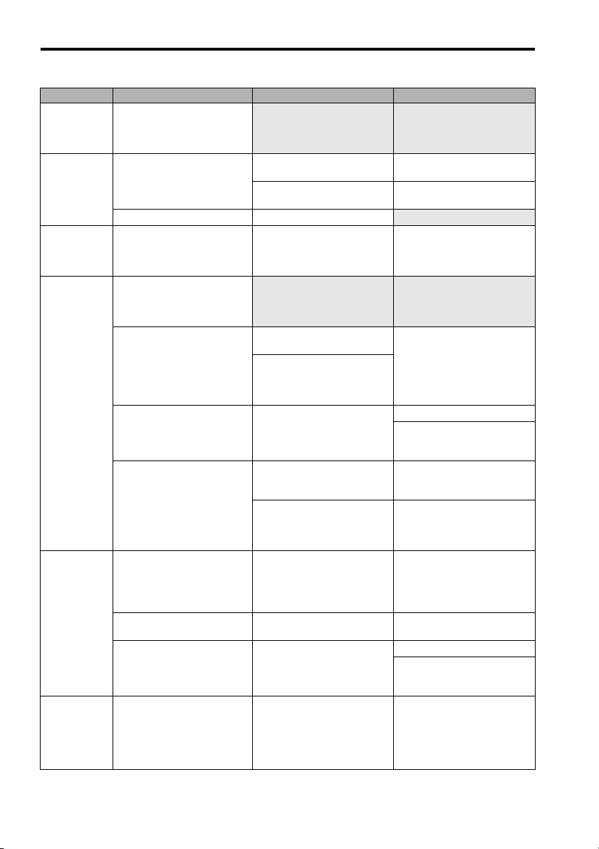
5.2 Troubleshooting for Malfunctions when Alarm Indicators Are Not Lit
Problem Cause Inspection Items Corrective Action
Servomotor
turns for a
moment and
stops.
Servomotor
turns even
without a reference.
Servomotor
turns in the
wrong direction.
Servomotor
operation is
not stable.
Motor overheated
The holding
brake does
not work.
The wiring of the servomotor
main circuit cable and
encoder cable is incorrect.
The reference pulse input is
not correct.
The SERVOPACK is faulty. − Replace the SERVOPACK.
The CW and CCW inputs are
connected backward.
The servomotor main circuit
cable or encoder cable is not
wired correctly.
Misalignment of the coupling
connecting the servomotor
shaft and machine, loose
screws, or load torque
changes resulting form pulley and gear engagement.
The load moment of inertia
exceeds the permissible
value of the SERVOPACK.
The connection of the pulse
signal wires is incorrect.
The ambient temperature
around the servomotor is too
high.
The ventilation is obstructed. Check to see if ventilation is
The servomotor is overloaded.
The holding brake power is
turned ON.
Check the order of phases U,
V, and W in the servomotor
main circuit cable and the
wiring of the encoder cable.
Check the reference pulse
type.
Check the voltage of the reference pulse.
Check the reference pulse
types of the controller and
the SERVOPACK.
Check the wiring of the servomotor main circuit cable
phases U, V, and W and the
encoder cable.
Check the coupling to the
machine system.
Operate the servomotor with
no load (i.e., disconnect the
servomotor from the
machine).
Operate the servomotor with
no load (i.e., disconnect the
servomotor from the
machine).
Check the wiring of the pulse
signal wires of the host controller and SERVOPACK.
Check the reference pulse
types of the controller and
the SERVOPACK.
Be sure that the ambient
temperature around the servomotor is 40 ° C or less.
obstructed.
Operate the servomotor with
no load (i.e., disconnect the
servomotor from the
machine).
Check to see if the holding
brake power is turned ON.
Correct the wiring.
Set the suitable reference
pulse type.
Connect a resistor according
to the voltage.
Connect the CW pulse signal
to the CW input and the CCW
pulse signal to the CCW
input.
Wire the cables correctly.
Review and adjust the
machine.
Reduce the load.
Replace the servomotor and
SERVOPACK with ones with
higher capacities.
Correct the wiring.
Set the pulse type of the
SERVOPACK according to
the reference pulse type of
the controller.
Reconsider the installation
conditions so that the ambient temperature will be 40 °C
or less. Cool down the servomotor with a fan or cooler.
Provide good ventilation.
Reduce the load.
Replace the servomotor and
SERVOPACK with ones with
higher capacities.
Design the circuit so that the
holding brake is turned OFF
when the holding brake
needs to hold the load when
the servomotor comes to a
stop.
52
Page 54

5.2 Troubleshooting for Malfunctions when Alarm Indicators Are Not Lit
Problem Cause Inspection Items Corrective Action
Servomotor
does not stop
operation
smoothly or
at all when
servo is
turned OFF.
Abnormal
noise from
Servomotor
or machine
vibrates.
The servomotor is overloaded.
Check to see if the load is
excessive or the servomotor
speed is too high.
Reconsider the load conditions and replace the SERVOPACK.
A stop circuit fault occurred. − Replace the SERVOPACK.
Mounting not secured. Check to see if there are any
Tighten the mounting screws.
loose mounting screws.
Check to see if the coupling
Align the coupling.
is misaligned.
Check to see if the coupling
Balance the coupling.
is unbalanced.
Defective bearings Check for the noise and
vibration around the bearings.
Vibration source on the
driven machine
Noise interference due to
incorrect input signal cable
specifications.
Noise interference because
the input signal cable is
longer than the applicable
range.
Noise interference because
the encoder cable specifications are incorrect.
Foreign matter, looseness, or
deformation on the machine
movable section.
Be sure that the twisted-pair
or shielded twisted-pair cable
with a core of at least
2
0.08 mm
The wiring distance must be
3 m max.
Check to see if a shielded
twisted-pair cable with a core
of at least 0.12 mm
is used.
2
is being
If there is a fault, contact your
OYMC representative.
(Contact the machine manufacturer.)
Use the specified input signal
cables.
Shorten the wiring distance
for input signal cable to 3 m
or less.
Use a cable that meets the
encoder cable specifications.
used.
Noise interference because
the encoder cable is longer
than the applicable range.
Noise is entering the encoder
cable because the sheath is
damage.
Excessive noise interference
on encoder cable.
FG potential varies due to
the influence of machines
such as a welder at the ser-
Check the length of the
encoder cable.
Check to see if the encoder
cable is damaged.
Check to see if the encoder
cable is bundled with highcurrent lines or near high-current lines.
Check to see if the machine
is correctly grounded properly.
The wiring distance must be
20 m or less.
Modify the encoder cable
layout so the cable is not
subjected to surge.
Install a surge protector on
the encoder cable.
Ground the machine
separately from the PG’s FG.
vomotor.
Excessive vibration and
shock on the encoder.
The filter setting is improper. Check the set value on the
Vibration from the machine
occurred or servomotor
installation is incorrect.
(Mounting surface accuracy,
securing, alignment, etc.)
reference filter (FIL) rotary
switch.
Reduce vibration from the
machine or secure the servomotor.
Increase the set value on the
reference filter (FIL) rotary
switch.
53
Page 55

6.1 Regular Inspections
6 Inspections
6.1 Regular Inspections
For inspection and maintenance of the SERVOPACK, follow the inspection procedures in the following
table at least once every year. Other routine inspections are not required.
Item Frequency Procedure Comments
Exterior At least once a year Check for dust, dirt, and oil on
Loose Screws Check for loose connector
the surfaces.
screws.
6.2 Part's Life Expectancy
The following electric or electrical parts are subject to mechanical wear or deterioration over time.
If an unusual noise or vibration occurs, refer to the life expectancy table and contact your OYMC representative. After examining the part in question, we will determine whether the parts should be replaced
or not. When the part has expired before the expected time, further inspection will be required.
Part Life Expectancy Comments
Cooling Fan 30,000 hours Life depends on operation conditions. Check that there is no
Note: 1. The life expectancy listed in the table is a reference period that may be affected by the environ-
mental and operating conditions.
2. The recommended models of the replacement cooling fans are:
SERVOPACK Model Manufacturer
SJDE-01APA to
04APA-OY
SJDE-08APA-OY JZSP-CHF08-2
unusual noise or vibration.
JZSP-CHF08-1 Sun-Wa Technos Co., Ltd.
http://www.sunwa.co.jp/
Clean with cloth or compressed air.
Tighten any loose screws.
54
Page 56

6.3 Replacement of Cooling Fan
6.3 Replacement of Cooling Fan
WARNING
• Do not open the SERVOPACK case for five minutes after the LED (PWR) is turned OFF.
Residual voltage may cause electric shock.
• Disconnect all power and wait at least 15 minutes before replacing the cooling fan.
Failure to observe this caution may cause burns due to heatsink’s high temperature.
• Be sure that the cooling fan is positioned in the correct direction when it is installed.
Failure to observe this caution may result in the malfunction of the SERVOPACK.
SERVOPACKs of 100 to 400 W
1. Open the case of the SERVOPACK.
Insert the tip of a straight-edge screw-
driver into the three notches on the
SERVOPACK one by one and pry the
case off.
Front of
SERVOPACK
Case
2. Lift up to remove the case.
Case
Cover
55
Page 57
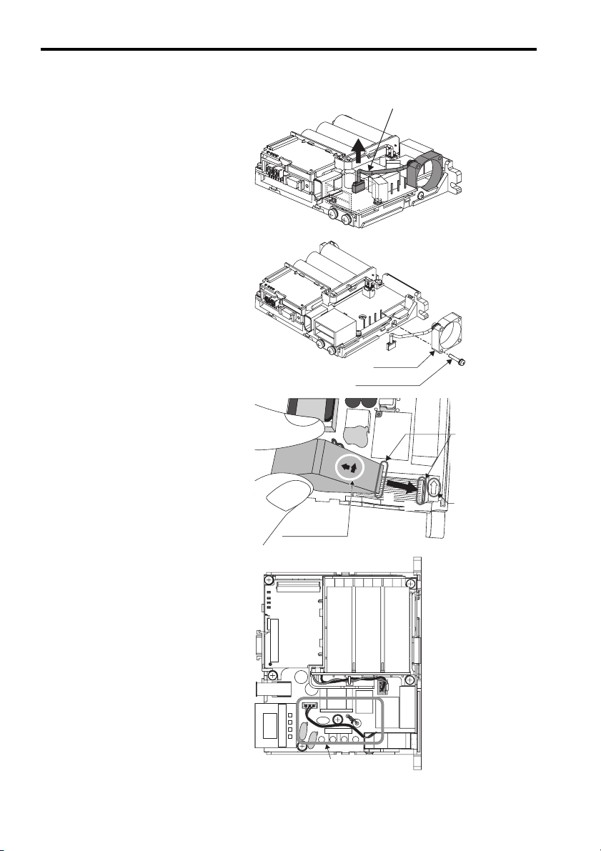
6.3 Replacement of Cooling Fan
3. Disconnect the cable of the cooling fan
from the fan connector on the SERVOPAC K.
4. Unscrew the cooling fan and remove it.
5. Install the new cooling fan.
(Type: JZSP-CHF08-1)
CAUTION: Before installing the new
cooling fan, make sure that
the arrow on the heatsink
and the arrow on the fan
face the same direction as
shown in the diagram.
6. Secure the new cooling fan on the
SERVOPACK with mounting screws.
Pick the cable up, and then pull it out.
Arrows on the
cooling fan side
Cooling fan
Mounting screw
Fit the edge (
of the cooling fan
into the position (
circled here.
Arrow on the
heatsink side
)
)
7. Connect the cooling-fan cable to the
fan connector on the SERVOPACK.
CAUTION: Make sure that the wiring
layout of the cable matches
that shown in the diagram.
8. Reattach the case and cover to the
SERVOPACK in their original positions.
Place the cooling-fan
cable as shown here.
56
Page 58

750 W SERVOPACKs
1. Open the case of the SERVOPACK.
Insert the tip of a straight-edge screw-
driver into the three notches on the
case and the two on the cover on the
SERVOPACK one by one and pry the
case off.
Front of
SERVOPACK
6.3 Replacement of Cooling Fan
Case
2. Pull the case and the cover off of the
SERVOPACK.
3. Disconnect the cable of the cooling fan
from the fan connector on the SERVOPAC K.
Case
Cover
Pick the cable up,
and then pull it out.
57
Page 59

6.3 Replacement of Cooling Fan
4. Remove the two mounting screws of
the cooling fan.
5. Install the new cooling fan.
Thread the cooling-fan cable through
the opening ( ) as shown in the dia-
C
gram A.
CAUTION: Make sure that the arrow on
the heatsink and the arrow
on the fan face the same
direction as shown in the
diagram B.
Cooling fan
Mounting screws
Diagram A
C
6. Secure the fan on the SERVOPACK
with mounting screws.
Diagram B
58
Make sure the direction
of the arrows on the fan
is the same as this diagram.
Page 60

7. Turn the SERVOPACK over, and then
connect the cooling-fan cable to the
fan connector on the SERVOPACK.
CAUTION: Make sure that the wiring
layout of the cable matches
that shown in the diagram.
8. Reattach the case and cover to the
SERVOPACK in their original positions.
6.3 Replacement of Cooling Fan
Place the cooling-fan
cable as shown here.
59
Page 61

7.1 Specifications
7 Specifications
7.1 Specifications
SERVOPACK model SJDE- 01APA-OY 02APA-OY 04APA-OY 08APA-OY
Max. applicable servomotor capacity
[kW]
Continuous output current [Arms] 0.84 1.1 2.0 3.7
Instantaneous max. output current
[Arms]
Input power supply
(for main circuit and control circuit)
Power loss at rated output [W] 14162435
Input control method Capacitor-input type, single-phase full-wave rectification
Output control method PWM control, sine wave power driven system
Feedback Analog output encoder
Allowable load inertia [kgm
Leakage current Power-sup-
I/O Signals
Voltage Single-phase 200 V to 230 VAC, +10 % to -15 %
Frequency 50/60Hz ± 5 %
Capacity at rated output [kVA]
2
]* 0.6× 10
ply frequency
High frequency
Pulse type Select one of the following signals:
Input signal for
reference
Designated pulse
type and pulse
resolution with
PULSE switch.
Clear input signal
Servo ON input signal
Alarm output signal
Brake output signal
Positioning completed output
signal
Origin output signal
Pulse resolution
0.1 0.2 0.4 0.75
2.5 3.3 6.0 11.1
0.40 0.75 1.2 2.2
with resistance to prevent inrush currents.
-4
5 mA or less
2.5 A0-p Motor cable length: 20 m max.
1. CCW + CW
2. Sign + pulse train
3. CCW + CW (logic reversal)
4. Sign + pulse train (logic reversal)
Select one of the following signals:
1. 1000 pulses/rev (Open collector/line driver) 75 kpps max.
2. 2500 pulses/rev (Open collector/line driver) 187.5 kpps max.
3. 5000 pulses/rev (Line driver) 375 kpps max.
4. 10000 pulses/rev (Line driver) 750 kpps max.
Clears the positioning error when turned ON.
Turns the servomotor on or off.
OFF if an alarm occurs.
Note: OFF for 2s when power is turned ON.
External signal to control brakes.
Turn ON to release the brake.
ON if the current position is equal to the reference position ±10
pulses.External signal to control brakes.
ON if the motor is at the origin. (Width: 1/500 rev)
Note: Use the pulse edge that changes the signal
from OFF to ON.
3× 10
-4
5× 10
-4
10× 10
-4
60
Page 62

7.2 Overload Protection Characteristics
SERVOPACK model SJDE- 01APA-OY 02APA-OY 04APA-OY 08APA-OY
Dynamic brake (DB)
Operated at main power OFF, servo alarm, servo OFF.
(OFF after motor stops; ON if the motor power is off.)
Regenerative processing
LED display
Built-in functions
Reference filter
Cooling method
Optional
(If the regenerated energy is too large, install a regenerative unit.)
5 (PWE, REF, AL1, AL2, AL3)
Select one of eight levels with FIL switch.
Forced cooling (built-in fan)
7.2 Overload Protection Characteristics
The SERVOPACK provides a function to protect the servomotor and SERVOPACK from overloads.
• If an overload alarm occurs, remove the cause of the alarm and wait for at least one minute. Turn
NOTE
The overload protection characteristics are shown below.
ON the servomotor again after the servomotor has cooled sufficiently. If the operation of the servomotor is repeated within a short time, the servomotor coil may burn out.
• Use a correct combination of the SERVOPACK and servomotor.
• Overload protection characteristics are the values used when the motor attached to the aluminum
heatsink [250 mm × 250 mm × 6 mm (23.62 in × 23.62 in × 0.24 in)] at the ambient temperature of
40 ° C (104 ° F). Make sure to use the SERVOPACK in the recommended operating conditions.
1000
SJME-01 (100W)
Example: If the Servomotor torque is 300 %,
an overload alarm will occur in
approximately two seconds.
Time (s)
100
10
1
100 150 200 250 300
Motor torque (%)
SJME-02 (200W) to SJME-08(750W)
1000
100
Time (s)
10
1
150 200 250 300
100
Motor torque (%)
Note: The servomotor torque is given as a percentage of the rated torque.
61
Page 63

OMRON EUROPE B.V.
Wegalaan 67-69, NL-2132 JD, Hoofddorp, The Netherlands.
Tel: +31 (0) 23 568 13 00 Fax: +31 (0) 23 568 13 88 www.omron-industrial.com
Austria
Tel: +43 (0) 1 80 19 00
www.omron.at
Belgium
Tel: +32 (0) 2 466 24 80
www.omron.be
Czech Republic
Tel: +420 234 602 602
www.omron.cz
Denmark
Tel: +45 43 44 00 11
www.omron.dk
Finland
Tel: +358 (0) 207 464 200
www.omron.fi
Manufacturer
YASKAWA
In the event that the end user of this product is to be the military and said product is to be employed in any weapons
systems or the manufacture thereof, the export will fall under the relevand regulations as stipulated in the Foreign Exchange
and Foreign Trade Regulations. Therefore, be sure to follow all procedures and submit all relevant documentation according
to any and all rules, regulations and laws may apply.
Specifications are subject to change without notice for ongoing product modifications and improvements.
© 2006 OMRON Yaskawa Motion Control. All rights reserved.
Note: Specifications subject to change without notice.
Manual No. TOEP-C71080601-01-OY
YASKAWA ELECTRIC CORPORATION
France
Tel: +33 (0) 1 56 63 70 00
www.omron.fr
Germany
Tel: +49 (0) 2173 680 00
www.omron.de
Hungary
Tel: +36 (0) 1 399 30 50
www.omron.hu
Italy
Tel: +39 02 32 681
www.omron.it
Middle East & Africa
Tel: +31 (0) 23 568 11 00
www.omron-industrial.com
Netherlands
Tel: +31 (0) 23 568 11 00
www.omron.nl
Norway
Tel: +47 (0) 22 65 75 00
www.omron.no
Poland
Tel: +48 (0) 22 645 78 60
www.omron.com.pl
Portugal
Tel: +351 21 942 94 00
www.omron.pt
Russia
Tel: +7 095 745 26 64
www.omron.ru
Spain
Tel: +34 913 777 900
www.omron.es
Sweden
Tel: +46 (0) 8 632 35 00
www.omron.se
Switzerland
Tel: +41 (0) 41 748 13 13
www.omron.ch
Turkey
Tel: +90 (0) 216 474 00 40 Pbx
www.omron.com.tr
United Kingdom
Tel: +44 (0) 870 752 08 61
www.omron.co.uk
 Loading...