

Page 1
SGLG@, SGLF@, SGLT@
Sigma linear motors
Direct drive linear servo motors for faster
machine cycles
• Direct control of the motors using XtraDrive and
Sigma-II drives
• Improved machine performance
• Easy of operation & high reliability
• Designed for high force density in compact
packages
• Exhibit exceptional force linearity even at near peak
force regions
• Extremely energy efficient, due to its optimized
magnetic circuitry design and high-density windings
• Can reach speeds as high as 5 meters per second.
• Coreless and iron core types available
Ratings
• 230 VAC Single-phase 12.5 to 560 N (1200 N Peak)
• 400 VAC Three-phase 80 to 2250 N (7500 N Peak)
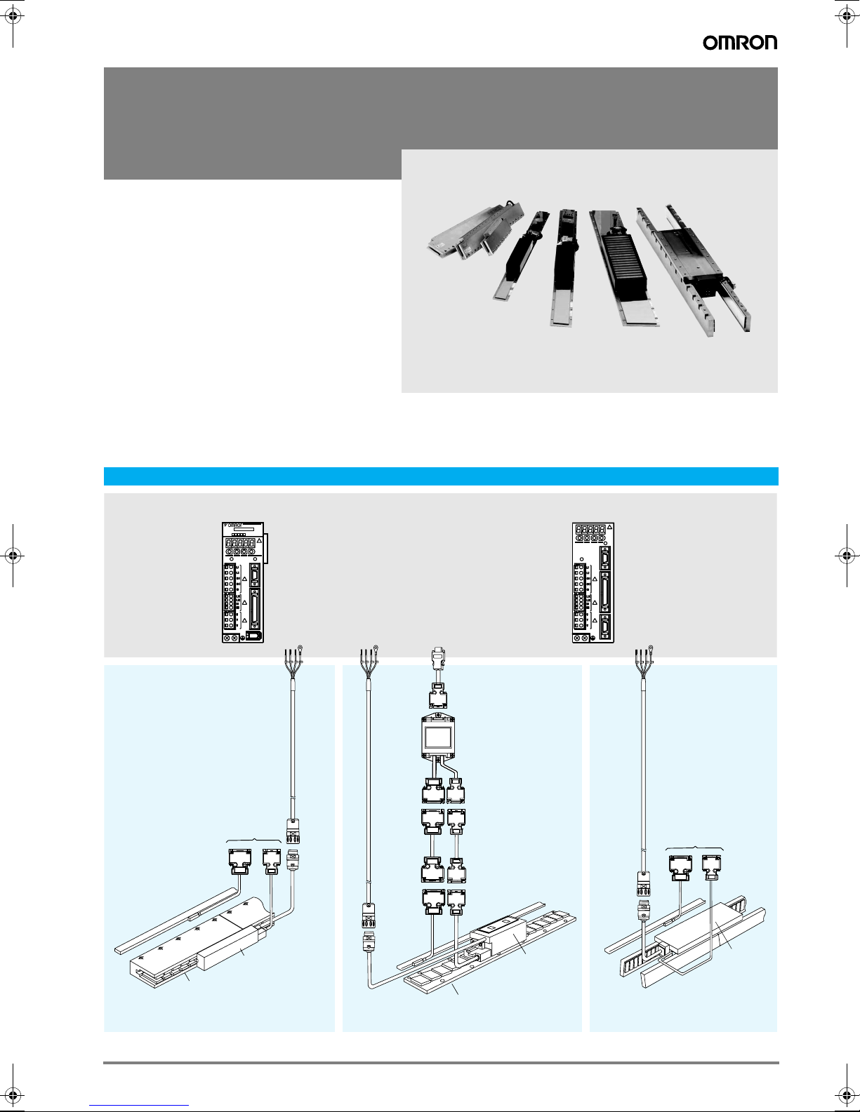
System configuration
(Refer to servo drive chapter)
SGDH-
Ver.
(To serial converter unit)
Linear
scale
Linear scale
CHARGE POWER
CN2
SERVOPACK
200V
Servo Drive with option
boards for
CN3
flexible system
configuration
CN1
Sigma-II
Servo Drive
Hall
sensor
Power
cable
Power
Power
cable
Linear scale
cable
(extension)
Linear
scale
Drive options
Serial
converter
cable
Serial converter
unit
Hall sensor
cable
(extension)
Power
cable
Hall
sensor
POWER
Intelligent
CN3
CHARGE
Servo Drive
CN1
XtraDrive
CN2
Power
cable
Power
(To serial converter unit)
Hall
Linear
scale
sensor
Linear coil
SGLGW
Magnetic way
SGLGM
SGLG_ Linear
Servo Motor
Power
SGLF_ Linear
Servo Motor
Magnetic way
SGLFM
Linear coil
SGLFW
Magnetic way
SGLTM
Linear coil
SGLTW
SGLT_ Linear
Servo Motor
195Sigma linear motors
Page 2
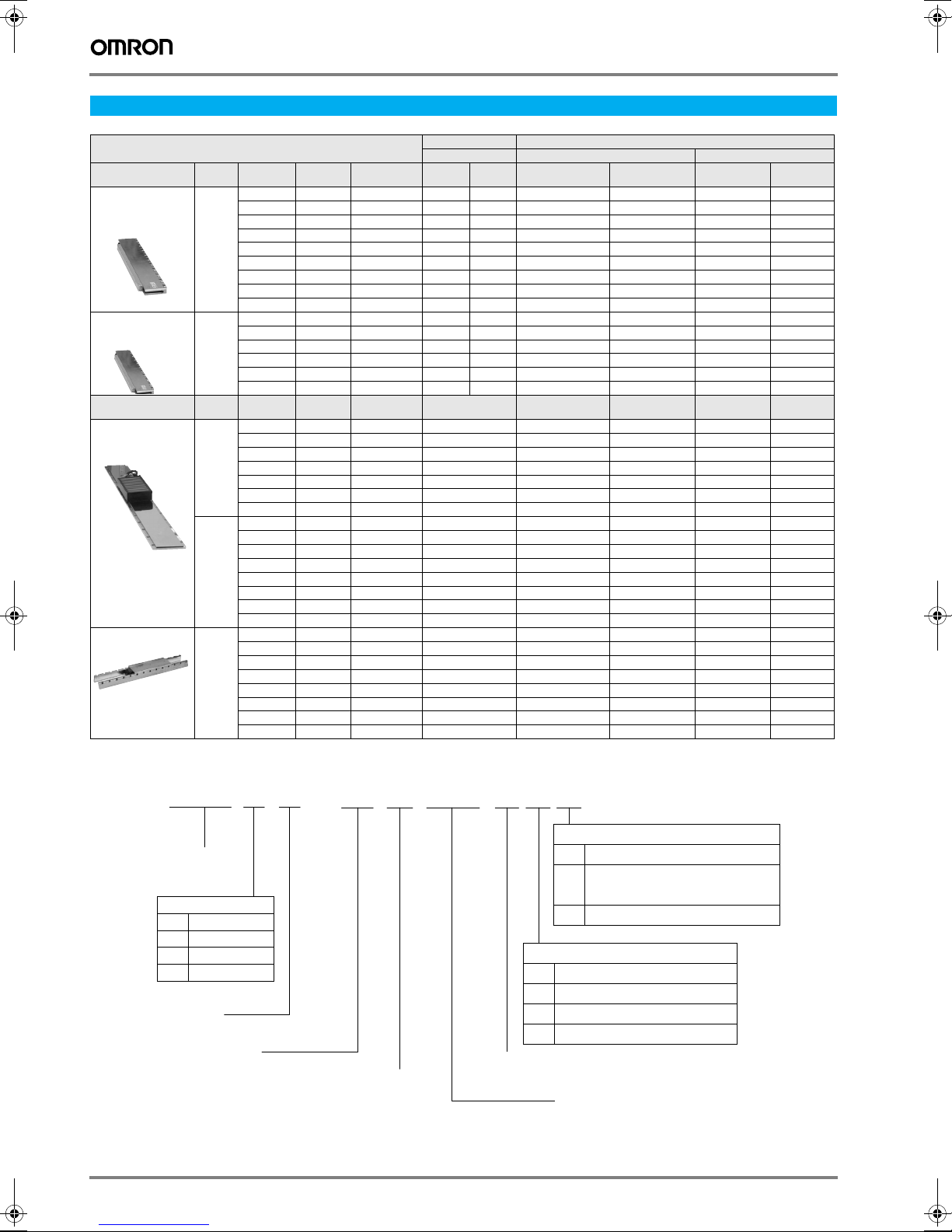
Servo Motor / Servo Drive Combination
Sigma series linear servo motor Serial converter Servo drive
Type Voltage Rated
SGLGW coreless
standard-force
magnetic ways
SGLGW coreless
high-force
magnetic ways
Type Voltage Rated
SGLFW
linear motors
SGLTW
linear motors
230 V 12.5 N 40 N 30A050 [B / C] 158 250 SGDH-A5AE-OY - XD-P5-MN01 -
230 V 57 N 230 N 40A140 [B / C] 059 255 SGDH-02AE-OY - XD-02-MN01 -
230 V 25 N 86 N 20A090A 017 SGDH-02AE-OY - XD-02-MN01
400 V 80 N 220 N 35D120A 211 - SGDH-05DE-OY - XD-05-TN
400 V 300 N 600 N 35D170H 193 - SGDH-10DE-OY - XD-10-TN
25 N 80 N 30A080 [B / C] 156 251 SGDH-01AE-OY - XD-01-MN01 47 N 140 N 40A140 [B / C] 001 252 SGDH-01AE-OY - XD-01-MN01 70 N 220 N 60A140 [B / C] 004 258 SGDH-02AE-OY - XD-02-MN01 93 N 280 N 40A253 [B / C] 002 253 SGDH-02AE-OY - XD-02-MN01 140 N 420 N 40A365 [B / C] 003 254 SGDH-04AE-OY - XD-04-MN01 140 N 440 N 60A253 [B / C] 005 259 SGDH-04AE-OY - XD-04-MN01 210 N 660 N 60A365 [B / C] 006 260 SGDH-08AE-S-OY - XD-08-MN 325 N 1300 N 90A200 [A / C] 101 264 SGDH-15AE-S-OY - XD-15-MN -
114 N 460N 40A253 [B / C] 060 256 SGDH-04AE-OY - XD-04-MN01 171 N 690 N 40A365 [B / C] 061 257 SGDH-08AE-S-OY - XD-08-MN 85 N 360N 60A140 [B / C] 062 261 SGDH-02AE-OY - XD-02-MN01 170 N 720 N 60A253 [B / C] 063 262 SGDH-08AE-S-OY - XD-08-MN 255 N 1080 N 60A365 [B / C] 047 263 SGDH-15AE-S-OY - XD-15-MN -
40 N 125 N 20A120A 018 SGDH-02AE-OY - XD-02-MN01
80 N 220 N 35A120A 019 SGDH-02AE-OY - XD-02-MN01
160 N 440 N 35A230A 020 SGDH-08AE-S-OY - XD-08-MN01
280 N 600 N 50A200B 181 SGDH-08AE-S-OY - XD-08-MN
560 N 1200 N 50A380B 182 SGDH-15AE-S-OY - XD-15-MN
560 N 1200 N 1ZA200B 183 SGDH-15AE-S-OY XD-15-MN
160 N 440 N 35D230A 212 - SGDH-05DE-OY - XD-05-TN
280 N 600 N 50D200B 189 - SGDH-10DE-OY - XD-10-TN
560 N 1200 N 50D380B 190 - SGDH-15DE-OY - XD-15-TN
560 N 1200 N 1ZD200B 191 - SGDH-15DE-OY - XD-15-TN
1120 N 2400 N 1ZD380B 192 - SGDH-30DE-OY - XD-30-TN
1500 N 3600 N 1ED380B 333 - SGDH-20DE-OY - XD-20-TN
2250 N 5400 N 1ED560B 334 - SGDH-30DE-OY - XD-30-TN
600 N 1200 N 35D320H 194 - SGDH-20DE-OY - XD-20-TN
450 N 900 N 50D170H 195 - SGDH-10DE-OY - XD-10-TN
900 N 1800 N 50D320H 196 - SGDH-20DE-OY - XD-20-TN
670 N 2600 N 40D400B 197 - SGDH-30DE-OY - XD-30-TN
1000 N 4000 N 40D600B 198 - SGDH-50DE-OY - XD-50-TN
1300 N 5000 N 80D400B 199 - SGDH-50DE-OY - XD-50-TN
2000 N 7500 N 80D600B 200 - SGDH-75DE-OY - -
Peak force Model code for
force
Peak force Model code 230 V
force
JZDP-@008-[code] Sigma-II series XtraDrive
Rev A, B
code for
Rev C
230 V
(1-phase)
(1-phase)
400 V
(3-phase)
400 V
(3-phase)
230 V
(1-phase)
230 V
(1-phase)
400 V
(3-phase)
400 V
(3-phase)
Motor coil
㧙
WFSGL
Linear Σ series
Linear servo motor
Servo motor model
Code
Specifications
G
Coreless
F-type iron core
F
T-type iron core
T
W : Coil assembly
Magnet height
196 AC servo systems
35 D 120 A P
Code
P
C
H
Design revision order
Voltage
A㧦200 VAC
D㧦400 VAC
A,B,C
D
Cable connector for main circuit cable
Code
MS connector or connector made
−
by Tyco Electronics AMP K.K.
Connector made by Interconnectron
D
With hall sensor (standard)
With hall sensor and forced cooling
Length of coil assembly
Specifications
Options
Specifications
Forced cooling
Page 3
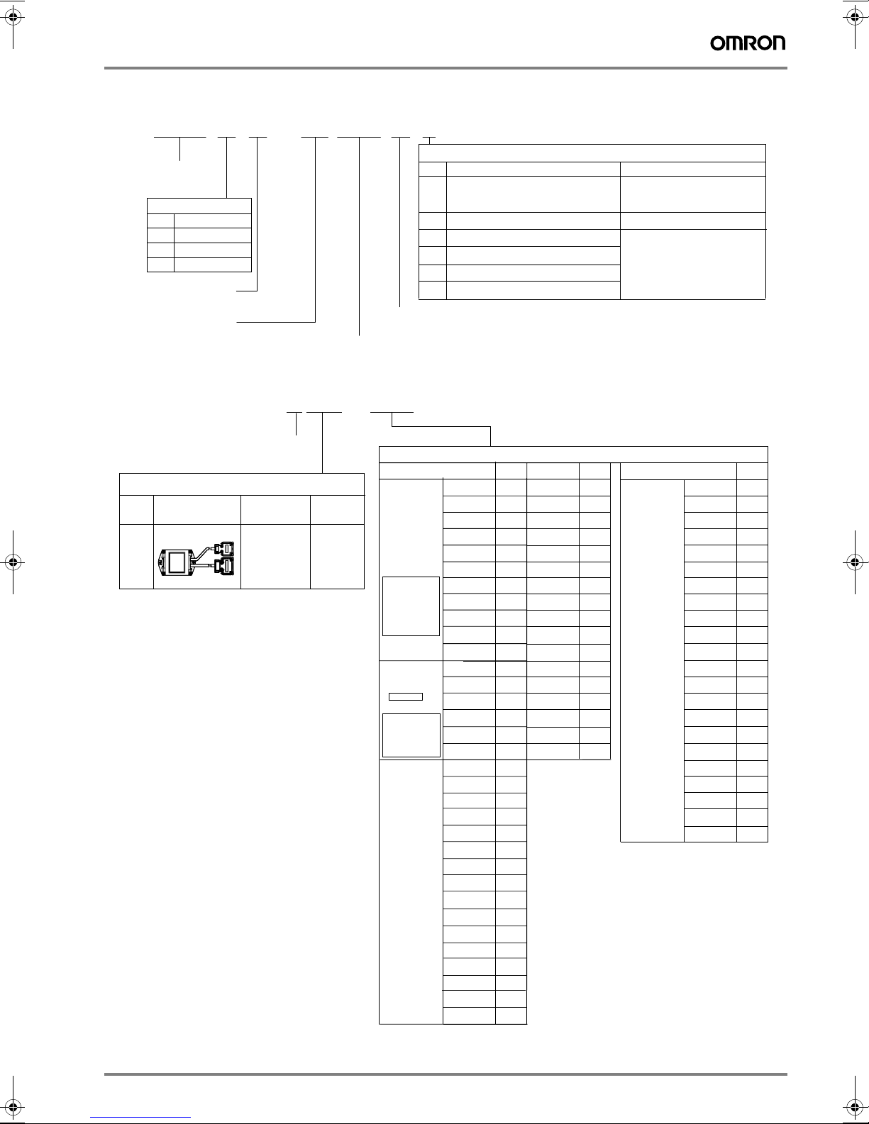
Magnetic way
SGL
FM
35 324 A C
Linear Σ series
Linear servo motor
Model
Code
Specifications
G
Coreless
F
F-type iron core
T
T-type iron core
M : Magnetic way
Magnet width
Length of magnetic way
Serial converter unit
D008JZDP – – 001
Design revision order
A,B,C
Serial converter unit model
Symbol
Note: * When using a linear scale made by Heidenhain an extension
cable is required
Appearance
A008
D008
Applicable
linear scale
Made by
Renishaw
or
(Heidenhain *)
Hall sensor
Yes
Code
C
With magnet cover
-Y
With base and magnet cover For SGLTM type
Mounting type 1
-M
Mounting type 1 & high thrust force
T-
Mounting type 2
T-M
Mounting type 2 & high thrust force
Design revision order
A,B,C
Servo motor model
30A050B
30A080B
40A140B
40A253B
SGLGW-
(coreless)
When a
standardforce
magnetic
way is used.
SGLGW +
SGLGM-
-M
(coreless)
When a
high-force
magnetic
way is used.
SGLFW-
(Iron core,
F-type)
40A365B
60A140B
60A253B
60A365B
90A200A
90A370A
90A535A
40A140B
40A253B
40A365B
60A140B
60A253B
60A365B
20A090A
20A120A
35A120A
35A230A
50A200B
50A380B
1ZA200B
1ZA380B
35D120A
35D230A
50D200B
50D380B
1ZD200B
1ZD380B
1ED380B
1ED560B
Options
Specifications Remarks
For iron-core types
- SGLFM
- SGLTM
For SGLGM type
Applicable linear servo motor
Symbol
158
156
001
002
003
004
005
006
101
102
103
059
060
061
062
063
047
017
018
019
020
181
182
183
184
211
212
189
190
191
192
333
334
Model
30A050C
30A080C
40A140C
40A253C
40A365C
60A140C
60A253C
60A365C
90A200C
90A370C
90A535C
40A140C
40A253C
40A365C
60A140C
60A253C
60A365C
Symbol
250
251
252
253
254
258
259
260
264
265
266
255
256
257
261
262
263
Servo motor model
SGLTW-
(Iron core,
T-type)
20A170A
20A320A
20A460A
35A170A
35A320A
35A460A
35A170H
35A320H
50A170H
50A320H
40A400B
40A600B
80A400B
80A600B
35D170H
35D320H
50D170H
50D320H
40D400B
40D600B
80D400B
80D600B
Symbol
011
012
013
014
015
016
105
106
108
109
185
186
187
188
193
194
195
196
197
198
199
200
Sigma linear motors 197
Page 4
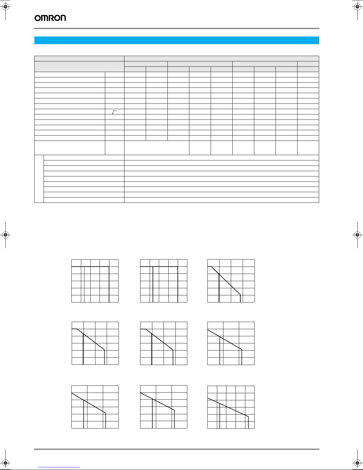
Servo motor specifications
Coreless SGLGW/SGLGM - (with standard-force magnetic ways)
Voltage 230 V
Linear servo motor
model SGLGW-
Rated force
Rated current
Instantaneous peak force
Instantaneous peak current
∗
∗
∗
∗
N 12.5 25 47 93 140 70 140 210 325
Arms 0,51 0,79 0.8 1.6 2.4 1,16 2,2 3,3 4.4
N 40 80 140 280 420 220 440 660 1300
Arms 1.62 2.53 2.4 4.9 7.3 3.5 7.0 10.5 17.6
Coil assembly weight kg 0.14 0.19 0.40 0.66 0.93 0.48 0.82 1.16 2.2
Force constant N / A
rms 26.4 33.9 61.5 61.5 61.5 66.6 66.6 66.6 78
BEMF constant V /(m / s) 8.8 11.3 20.5 20.5 20.5 22.2 22.2 22.2 26.0
Motor constant 3.7 5.6 7.8 11.0 13.5 11.1 15.7 19.2 26.0
Electrical time constant ms 0.2 0.4 0.4 0.4 0.4 0.5 0.5 0.5 1.4
N /
w
Mechanical time constant ms 7.30 4.78 5.59 4.96 4.77 3.41 3.08 2.98 3.18
Thermal resistance (with heat sink) K / W 5,19 3,11 1,67 0,87 0,58 1,56 0,77 0,51 0,39
Thermal resistance (without heat sink) K / W - - 3,02 1,80 1,23 2,59 1,48 1,15 1.09
Magnetic attraction N 000000000
Heat sink size mm 200 x
Time rating Continuous
Insulation class Class B
Ambient temperature 0 to +40 °C
Ambient humidity 20 to 80% (non-condensing)
Insulation resistance 500 VDC, 10 MΩ min.
Excitation Permanent magnet
Dielectric strength 1500 VAC for 1 minute
Basic specifications
Protection methods Self-cooled, air-cooling
Allowable winding temperature 130 °C
30A 40A 60A 90A
050C 080C 140C 253C 365C 140C 253C 365C 200C
300 x
12
300 x
400 x
12
400 x
500 x
12
200 x
300 x
12
300 x
400 x
12
400 x
500 x
12
800 x
900 x
12
Note: 1. The items marked with an * and “force and speed characteristics” are the values at a motor winding temperature of 100 °C during oper-
ation in combination with a servo drive. The others are at 20 °C (68°F).
2. The above specifications show the values under the cooling condition when a heat sink (aluminium board) listed in the following table is
mounted on the coil assembly.
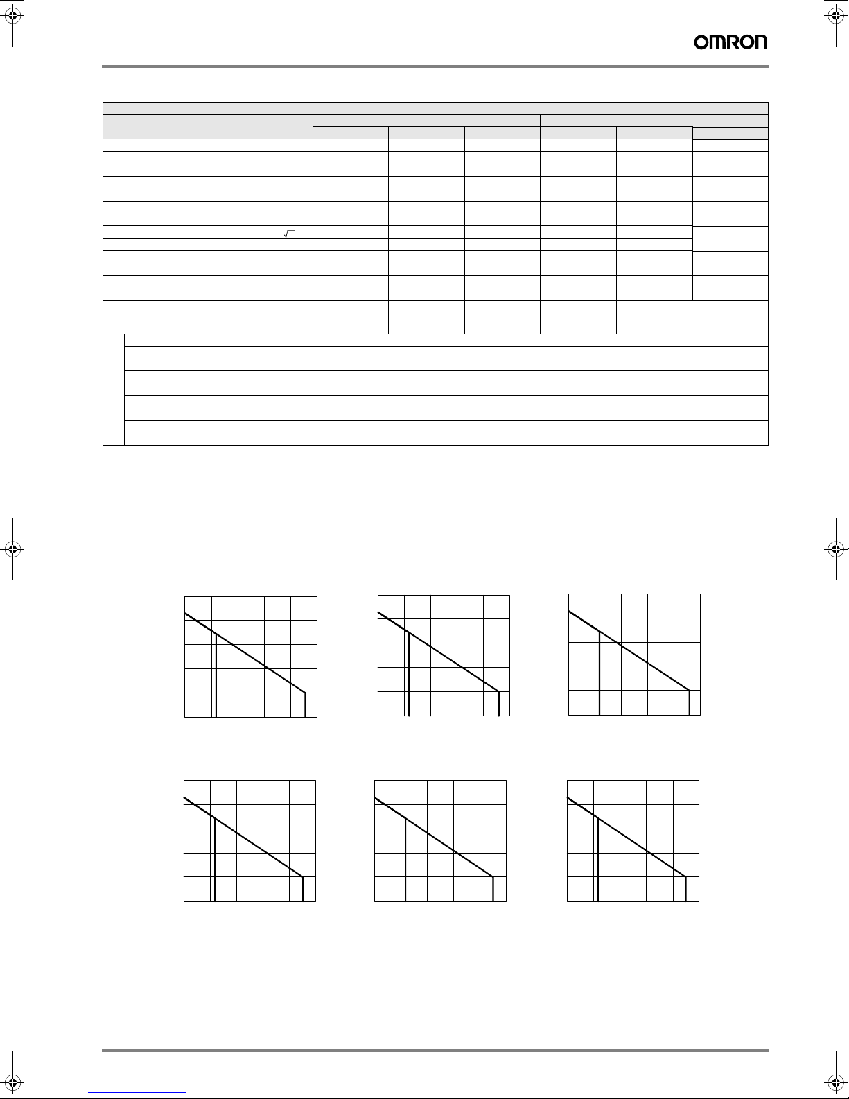
Force-speed characteristics - (with standard-force magnetic ways)
A: Continuous duty zone
B: Intermittent duty zone
SGLGW-30A050C
6.0
5.0
Motor
4.0
speed
3.0
(m/s)
A
2.0
1.0
0
0 10203040
SGLGW-40A253C
6.0
5.0
Motor
4.0
speed
(m/s)
Motor
speed
(m/s)
A
3.0
2.0
1.0
0
0 100 200 300 400
SGLGW-60A253C
6.0
5.0
4.0
A
3.0
2.0
1.0
0
0 200 400 600
Force (N)
Force (N)
Force (N)
SGLGW-30A080C
6.0
5.0
Motor
4.0
speed
3.0
(m/s)
B
50
A
2.0
1.0
0
0 20406080
Force (N)
Motor
speed
(m/s)
B
100
SGLGW-40A365C
6.0
5.0
Motor
4.0
speed
(m/s)
B
Motor
speed
(m/s)
B
A
3.0
2.0
1.0
0
0 150 300 450 600
SGLGW-60A365C
6.0
5.0
4.0
A
3.0
2.0
1.0
0
0 300 600 900
B
Force (N)
B
Force (N)
Motor
speed
(m/s)
Motor
speed
(m/s)
SGLGW-40A140C
6.0
5.0
4.0
A
3.0
2.0
1.0
0
0 50 100 150 200
SGLGW-60A140C
6.0
5.0
4.0
A
3.0
2.0
1.0
0
0 100 200 300
SGLGW-90A200C
6.0
5.0
4.0
A
3.0
2.0
1.0
0
0 300 600 900 1200 1500
B
Force (N)
B
Force (N)
Force (N)
B
198 AC servo systems
Page 5
Coreless SGLGW/SGLGM - (with high-force magnetic ways)
Voltage 230 V
Linear servo motor
model SGLGW-
Rated force
Rated current
Instantaneous peak force
Instantaneous peak current
Coil assembly weight kg 0.40 0.66 0.93 0.48 0.82 1.16
Force constant N / A
BEMF constant V /(m / s) 25.3 25.3 25.3 25.8 25.8 25.8
Motor constant 9.6 13.6 16.7 12.9 18.2 22.3
Electrical time constant ms 0.4 0.4 0.4 0.5 0.5 0.5
Mechanical time constant ms 3.69 3.24 3.12 2.52 2.29 2.21
Thermal resistance (with heat sink) K / W 1.67 0.87 0.58 1.56 0.77 0.51
Thermal resistance (without heat sink) K / W 3.02 1.80 1.23 2.59 1.48 1.15
Magnetic attraction N 0 0 0 0 0 0
Heat sink size mm 200 x
∗
∗
∗
∗
N 57 114 171 85 170 255
Arms 0.81.62.41.22.23.3
N 230 460 690 360 720 1080
Arms 3.2 6.5 9.7 5.0 10.0 14.9
rms 76.0 76.0 76.0 77.4 77.4 77.4
N /
w
Time rating Continuous
Insulation class Class B
Ambient temperature 0 to +40 °C
Ambient humidity 20 to 80% (non-condensing)
Insulation resistance 500 VDC, 10 MΩ min.
Excitation Permanent magnet
Dielectric strength 1500 VAC for 1 minute
Basic specifications
Protection methods Self-cooled, air-cooling
Allowable winding temperature 130 °C
140C 253C 365C 140C 253C 365C
300 x
12
40A 60A
300 x
400 x
12
400 x
500 x
12
200 x
300 x
12
300 x
400 x
400 x
12
500 x
12
Note: 1. The items marked with an * and “force and speed characteristics” are the values at a motor winding temperature of 100 °C during oper-
ation in combination with a servo drive. The others are at 20 °C (68°F).
2. The above specifications show the values under the cooling condition when a heat sink (aluminium board) listed in the following table is
mounted on the coil assembly.
Force-speed characteristics - (with high-force magnetic ways)
A: Continuous duty zone
B: Intermittent duty zone
SGLGW-40A365C
5
4
3
2
A
1
0
0 150 450300 600 750
B
Force (N)
SGLGW-60A365C
5
4
3
2
A
1
0
0 240 720480 960 1200
B
Force (N)
Motor
speed
(m/s)
Motor
speed
(m/s)
SGLGW-40A140C
5
4
3
2
A
1
0
0 50 150100 200 250
B
Force (N)
SGLGW-60A140C
5
4
3
2
A
1
0
0 80 240160 320 400
B
Force (N)
Motor
speed
(m/s)
Motor
speed
(m/s)
SGLGW-40A253C
5
4
3
2
A
1
0
0 100 300200 400 500
B
Force (N)
SGLGW-60A253C
5
4
3
2
A
1
0
0 160 480320 640 800
B
Force (N)
Motor
speed
(m/s)
Motor
speed
(m/s)
Sigma linear motors 199
Page 6
Iron-core SGLFW/SGLFM (200 V)
Voltage 230 V
Linear servo motor
model SGLFW-
Rated force
Rated current
Instantaneous peak force
Instantaneous peak current
∗
∗
∗
∗
N 25 40 80 160 280 560 560
Arms 0.7 0.8 1.4 2.8 5.0 10.0 8.7
N 86 125 220 440 600 1200 1200
Arms 3.0 2.9 4.4 8.8 12.4 25.0 21.6
Coil assembly weight kg 0.7 0.9 1.3 2.3 3.5 6.9 6.4
Force constant N / A
rms 36.0 54.0 62.4 62.4 60.2 60.2 69.0
BEMF constant V /(m / s) 12.0 18.0 20.8 20.8 20.1 20.1 23.0
Motor constant 7.9 9.8 14.4 20.4 34.3 48.5 52.4
Electrical time constant ms 3.2 3.3 3.6 3.6 15.9 15.8 18.3
N /
w
Mechanical time constant ms 11.0 9.3 6.2 5.5 3.0 2.9 2.3
Thermal resistance (with heat sink) K / W 4.35 3.19 1.57 0.96 0.82 0.32 0.6
Thermal resistance (without heat sink) K / W 7.69 5.02 4.10 1.94 1.48 0.74 0.92
Magnetic attraction N 314 462 809 1586 1650 3260 3300
Heat sink size mm 125 x 125 x 13 254 x 254 x 25 400 x 500 x 40 254 x 254 x 25
Time rating Continuous
Insulation class Class B
Ambient temperature 0 to +40 °C
Ambient humidity 20 to 80% (non-condensing)
Insulation resistance 500 VDC, 10 MΩ min.
Excitation Permanent magnet
Dielectric strength 1500 VAC for 1 minute
Basic specifications
Protection methods Self-cooled
Allowable winding temperature 130 °C
20A 35A 50A 1ZA
090A 120A 120A 230A 200B 380B 200B
Note: 1. The items marked with an * and “force and speed characteristics” are the values at a motor winding temperature of 100 °C during oper-
ation in combination with a servo drive. The others are at 20 °C (68°F).
2. The above specifications show the values under the cooling condition when a heat sink (aluminium board) listed in the following table is
mounted on the coil assembly.
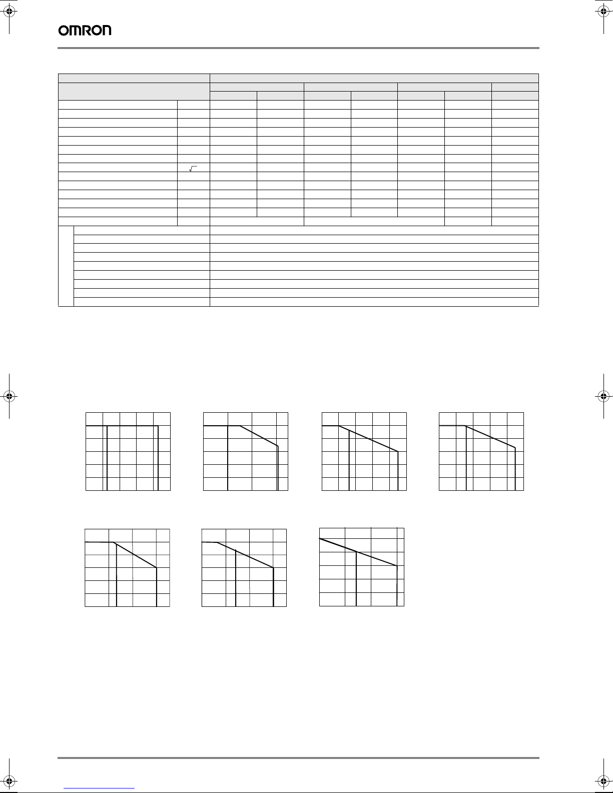
Force-speed characteristics (200 V)
A: Continuous duty zone
B: Intermittent duty zone
SGLFW-20A090A
6
5
Motor
4
speed
3
(m/s)
A B
2
1
0
0 20 40 60 80 100
Force (N)
SGLFW-50A200B
6
5
Motor
4
speed
3
(m/s)
2
1
0
0 400200 600
Force (N)
Motor
speed
(m/s)
Motor
speed
BA
(m/s)
SGLFW-20A120A SGLFW-35A120A SGLFW-35A230A
6
5
4
3
A
2
1
0
0 40 80 120 140
Force (N)
SGLFW-50A380B
6
5
4
3
2
1
0
0 800400 1200
Force (N)
BA
6
5
Motor
4
speed
(m/s)
B
3
A
2
1
0
0 50 100 150 200 250
6
5
4
Motor
speed
3
(m/s)
2
1
0
0 800400 1200
Force (N)
SGLFW-1ZA200B
B
BA
Force (N)
6
5
Motor
4
speed
3
(m/s)
A
2
1
0
0 100 200 300 400 500
B
Force (N)
200 AC servo systems
Page 7
Iron-core SGLFW/SGLFM (400 V)
Voltage 400 V
Linear servo motor
model SGLFW-
Rated force
Rated current
Instantaneous peak force
Instantaneous peak current
∗
∗
∗
∗
N 80 160 280 560 560 1120 1500 2250
Arms 0.7 1.4 2.3 4.5 4.9 9.8 6.4 9.6
N 220 440 600 1200 1200 2400 3600 5400
Arms 2.3 4.6 5.6 11.0 12.3 24.6 18.1 27.2
Coil assembly weight kg 1.3 2.3 3.5 6.9 6.4 11.5 22 33
Force constant N / A
rms 120.2 120.2 134.7 134.7 122.6 122.6 250 250
BEMF constant V /(m / s) 40.1 40.1 44.9 44.9 40.9 40.9 83.2 83.2
Motor constant 13.8 19.5 33.4 47.2 51.0 72.1 95.4 117
Electrical time constant ms 3.5 3.5 15.0 15.0 17.4 17.2 19.7 19.6
N /
w
Mechanical time constant ms 5.5 5.5 3.2 3.2 2.5 2.2 1.8 1.8
Thermal resistance (with heat sink) K / W 1.57 0.96 0.82 0.32 0.6 0.28 0.21 0.13
Thermal resistance (without heat sink) K / W 4.1 1.94 1.48 0.74 0.92 0.55 0.50 0.35
Magnetic attraction N 810 1590 1650 3260 3300 6520 9780 14600
Heat sink size mm 254 x 254 x 25 400 x 500
Time rating Continuous
Insulation class Class B
Ambient temperature 0 to +40 °C
Ambient humidity 20 to 80% (non-condensing)
Insulation resistance 500 VDC, 10 MΩ min.
Excitation Permanent magnet
Dielectric strength 1500 VAC for 1 minute
Basic specifications
Protection methods Self-cooled
Allowable winding temperature 130 °C
35D 50D 1ZD 1ED
120A 230A 200B 380B 200B 380B 380B 560B
x 40
254 x 254
x 25
400 x 500
x 40
609 x 762
x 50
762 x 1270
x 64
Note: 1. The items marked with an * and “force and speed characteristics” are the values at a motor winding temperature of 100 °C during oper-
ation in combination with a servo drive. The others are at 20 °C (68°F).
2. The above specifications show the values under the cooling condition when a heat sink (aluminium board) listed in the following table is
mounted on the coil assembly.
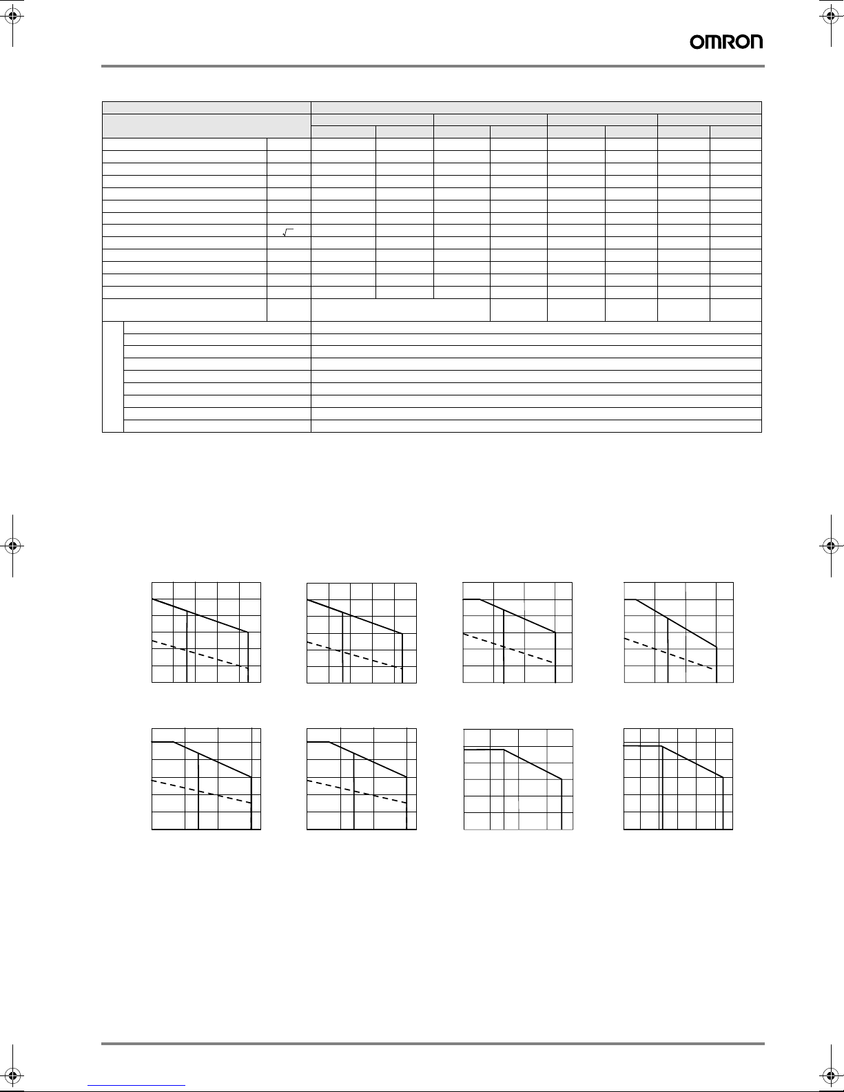
Force-speed characteristics (400 V)
A: Continuous duty zone
B: Intermittent duty zone
SGLFW-35D120A
6
5
Motor
4
speed
3
(m/s)
2
1
0
0 15050 100 200
SGLFW-1ZD200B
6
5
4
Motor
speed
3
(m/s)
2
1
0
0 800400 1200
Force (N)
A
Force (N)
SGLFW-35D230A
6
5
Motor
4
speed
(m/s)
BA
250
B
3
2
1
0
0 100 200 300 400 500
6
5
4
Motor
speed
3
(m/s)
2
1
0
0
Force (N)
SGLFW-1ZD380B
A
Force (N)
BA
B
1600800 2400
Motor
speed
(m/s)
Motor
speed
(m/s)
SGLFW-50D200B
6
5
4
3
A
2
1
0
0 400200 600
3.0
2.5
2.0
1.5
1.0
0.5
0
0
Force (N)
SGLFW-1ED380B
A
1000
2000
Force (N)
Motor
speed
4000
(m/s)
Motor
speed
(m/s)
B
B
3000
SGLFW-50D380B
6
5
4
3
A
2
1
0
0 800400 1200
Force (N)
SGLFW-1ED560B
3.0
2.5
2.0
A
1.5
1.0
0.5
0
0
30002000 5000
Force (N)
B
B
600040001000
Note: The dotted line indicates characteristics when the linear servo motor for 400 VAC is used with an input power supply for 200 VAC. In this
case, the serial converter should be changed. Contact your OMRON Yaskawa representatives.
Sigma linear motors 201
Page 8

Iron-core SGLTW/SGLTM (400 V)
Voltage 400 V
Linear servo motor
model SGLTW-
Rated force
Rated current
Instantaneous peak force
Instantaneous peak current
∗
∗
∗
∗
N 300 600 450 900 670 1000 1300 2000
Arms 3.2 6.5 3.2 6.3 3.7 5.5 7.2 11.1
N 600 1200 900 1800 2600 4000 5000 7500
Arms 7.5 15.1 7.3 14.6 20.7 30.6 37.6 56.4
Coil assembly weight kg 4.7 8.8 6 11 15 23 25 36
Force constant N / A
rms 99.6 99.6 153.3 153.3 196.1 196.1 194.4 194.4
BEMF constant V /(m / s) 33.2 33.2 51.1 51.1 65.4 65.4 64.8 64.8
Motor constant 36.3 51.4 48.9 69.1 59.6 73 85.9 105.2
Electrical time constant ms 14.3 14.3 15.6 15.6 14.4 14.4 15.4 15.4
N /
w
Mechanical time constant ms 3.5 3.5 2.5 2.5 4.2 4.2 3.2 3.2
Thermal resistance (with heat sink) K / W 0.76 0.4 0.61 0.3 0.24 0.2 0.22 0.18
Thermal resistance (without heat sink) K / W 1.26 0.83 0.97 0.8 0.57 0.4 0.47 0.33
Magnetic attraction
Magnetic attraction
∗1
∗2
N 00000000
N 1400 2780 2000 3980 3950 5890 7650 11400
Heat sink size mm 400 x 500 x 40 609 x 762 x 50
Time rating Continuous
Insulation class Class B
Ambient temperature 0 to +40 °C
Ambient humidity 20 to 80% (non-condensing)
Insulation resistance 500 VDC, 10 MW min.
Excitation Permanent magnet
Dielectric strength 1500 VAC for 1 minute
Basic specifications
Protection methods Self-cooled
Allowable winding temperature 130 °C
*1. The unbalanced magnetic gap resulting from the coil assembly installation condition causes a magnetic attraction on the coil assembly.
*2. The value indicates the magnetic attraction generated on one side of the magnetic way.
Note: 1. The items marked with an * and “force and speed characteristics” are the values at a motor winding temperature of 100 °C during oper-
ation in combination with a servo drive. The others are at 20 °C (68 °F).
2. The above specifications show the values under the cooling condition when a heat sink (aluminium board) listed in the following table is
mounted on the coil assembly.
35D 50D 40D 80D
170H 320H 170H 320H 400B 600B 400B 600B
Force-speed characteristics (400 V)
A: Continuous duty zone
B: Intermittent duty zone
SGLTW-35D170H SGLTW-35D320H
5
4
Motor
3
speed
(m/s)
2
1
0
0 400200 600
BA
Force (N)
6
5
Motor
4
speed
(m/s)
3
2
1
0
0 800400 1200
Force (N)
Motor
speed
BA
(m/s)
SGLTW-40D400B SGLTW-40D600B
Motor
speed
(m/s)
4
3
A
2
1
0
0 40002000
Motor
speed
(m/s)
B
4
3
Motor
speed
(m/s)
A
2
1
0
0 20001000 3000
Force (N) Force (N)
B
Note: The dotted line indicates characteristics when the linear servo motor for 400 VAC is used with an input power supply for 200 VAC. In this
case, the serial converter should be changed. Contact your OMRON Yaskawa representatives.
SGLTW-50D170H SGLTW-50D320H
5
4
3
2
1
0
0 600300 900
Force (N) Force (N)
BA
5
4
Motor
3
speed
(m/s)
2
1
0
0 1200600 1800
SGLTW-80D400B SGLTW-80D600B
4
3
A
2
1
0
0 4000 60002000
B
Force (N) Force (N)
Motor
speed
(m/s)
4
3
2
1
0
0 4000 6000 80002000
A
BA
B
202 AC servo systems
Page 9

Dimensions
Coreless SGLG@-30
Coil assembly: SGLGW-30A@@@@@D
Coil assembly model
SGLGW-
30A050D 50 48 30 20 20 0.85 0.14 *The value indicates the weight of coil assembly with a
30A080D 80725030250.95 0.19
Magnetic way: SGLGM-30@@@A
Magnetic way model
SGLGM-
30108A 108 54 2 0.6
30216A 216 162 4 1.1
30432A 432 378 8 2.3
L1 L2 L3 L4 L5 G(Gap) Approx.
2×screw
#4-40 UNC
Cable
UL20276,AWG26
22
12
44
(57)
(1)
G (Gap)
24
Hall sensor
connector specifications
9
5
Pin connector type:
17JE-23090-02 (D8C)
made by DDK Ltd.
The mating connector
Socket connector type:
17JE-13090-02 (D8C)
Stud type:17L-002C or
17L-002C1
L1
mm
G (Gap)
6
1
L2
mm
Name
plate
±50
(φ5.3)
500
(φ5)
AW
ޓغޓغ
N
Ins.
YASKAWA ELECTRIC CORPORATION JAPAN
Pin No.
Name
+5V (Power supply)
1
Phase U
2
Phase V
3
Phase W
4
0V (Power supply)
5
Not used
6
Not used
7
Not used
8
Not used
9
N Approx. weight
ߌ߇ߩᕟࠇࠅ
⏛ᕈࠍㄭߠߌࠆߥ㧍
May cause injury.
ෂ㒾
Keep magnetic materials
away.
9#40+0)
±50
500
Linear servo motor
Connector specifications
1
6
7
5
The coil assembly moves in the direction indicated by the arrow
when current flows in the order of phase U, V, and W.
Cable
UL2517,AWG25
L1
15
L3
L2
2
Extension: SROC06JMSCN169
3
Pin type: 021.423.1020
made by Interconnectron
4
The mating connector
Plug type: SPOC06KFSDN169
Name
Pin No.
Phase U
1
Phase V
2
Phase W
3
Not used
4
5
Not used
FG
6
Not used
7
kg
∗
weight
kg
17
L5
2×2-M4
Mounting screw depth: 5 mm on both sides
3
48.5
Units: mm
Hall sensor output signals
When the coil assembly moves in the
direction indicated by the arrow in the
figure, the relationship between the hall
sensor output signals Su, Sv, Sw and
the inverse power of each motor phase
Vu, Vv, Vw becomes as shown in the
following figure.
Lead color
Red
White
Blue
Green/yellow
Inverse
power
(V)
hall sensor unit.
4×M4 mounting screw,
depth 5
L4
Vu
Su
Vv
Sv
Vw
0 180 360 540
Electrical angle (° )
Sw
Name plate
CORELESS LINEAR SERVO MOTOR
غغغغغ㧙غغغغغغغغ
ޓغޓغ
W
ޓغޓغ
N
㧻㧛㧺غغغغغغ㧙غ
㧿㧛㧺غغغغغغغغغغغغغغغ
YASKAWA ELECTRIC CORPORATION JAPAN
A
غޓغ
Ins.
غ
Warning label
ෂ㒾
WARNING
4.5
36
Sigma linear motors 203
ߌ߇ߩᕟࠇࠅ
⏛ᕈࠍㄭߠߌࠆߥ㧍
May cause injury.
Keep magnetic materials
away.
Pitch 54
N×4.5 holes
8×counter boring 5L
L2
-0.1
L1 (1 unit)
-0.3
(18)
7.6
44
24
Units: mm
Page 10

Coreless SGLG@-40
Coil assembly: SGLGW-40A@@@@@D
Coil assembly model
SGLGW-
40A140D 140 125 90 30 52.5 45 3 4 0.40 *The value indicates the weight
40A253D 252.5 237.5 180 37.5 60 135 5 8 0.66
40A365D 365 350 315 30 52.5 270 8 14 0.93
L1 L2 L3 L4 L5 L6 N1 N2 Approx.
weight
kg
∗
of coil assembly with a hall sensor unit.
2×screw
#4-40 UNC
±50
25.4
6.5
4.8
±50
500
(φ5.3)
7.2
500
(φ
7)
0.5
14
15
1
30
L5
45
17
The coil assembly moves in the direction indicated by the arrow in the order of phase U, V, and W.
16
L4
45
4
78
L6
Mounting holes
N2×M4 tapped, depth 6 mm
L1
L3
Mounting holes on both sides
N1×M4 tapped, depth 6mm
Name plate
W
N
Ins.
㧻㧛㧺غغغغغغ㧙غ
㧿㧛㧺غغغغغغغغغغغغغغغ
YASKAWA ELECTRIC CORPORATION JAPAN
(7.5)
15
63
7
Gap 0.8
Gap 0.8
Hall sensor
connector specifications
9
5
Pin connector type:
17JE-23090-02 (D8C)
made by DDK Ltd.
The mating connector
Socket connector type:
17JE-13090-02 (D8C)
Stud type: 17L-002C or
ޓޓޓޓޓ17L-002C1
Linear servo motor
Pin No.
6
1
+5V (Power supply)
1
2
3
4
0V (Power supply)
5
6
7
8
9
Name
Phase U
Phase V
Phase W
Not used
Not used
Not used
Not used
connector specifications
2
1
Extension: SROC06JMSCN169
3
6
Pin type: 021.423.1020
made by Interconnectron
7
4
The mating connector
5
Plug type: SPOC06KFSDN169
Pin No.
Phase U
1
2
Phase W
3
Not used
4
5
Not used
6
Not used
7
Name
Phase V
FG
Lead color
Red
White
Blue
Green/yellow
Hall sensor output signals
When the coil assembly moves in the direction indicated by the arrow in the figure, the relationship between the hall sensor output signals Su, Sv, Sw and the inverse power of
each motor phase Vu, Vv, Vw becomes as
shown in the figure below.
Vu
Su
Inverse
Vv
power
(V)
Sv
Vw
0 180 360 540
Electrical angle (° )
Units: mm
Sw
Standard-force magnetic way: SGLGM-40@@@C@ High-force magnetic way: SGLGM-40@@@C@-M
Standard-force magnetic way
model SGLGM-
Mounting
type 1
Mounting
type 2
40090C 40090CT 90 45 2 0.8
40225C 40225CT 225 180 5 2.0
40360C 40360CT 360 315 8 3.1
40405C 40405CT 405 360 9 3.5
40450C 40450CT 450 405 10 3.9
L1mmL2 mmN Approx. weight
kg
High-force magnetic way model
Mounting
type 1
SGLGM-
Mounting
type 2
L1
L2 mmN Approx. weight
mm
40090C-M 40090CT-M 90 45 2 1.0
40225C-M 40225CT-M 225 180 5 2.6
40360C-M 40360CT-M 360 315 8 4.1
40405C-M 40405CT-M 405 360 9 4.6
40450C-M 40450CT-M 450 405 10 5.1
kg
-0.1
(1 unit)
L1
-0.3
%14'.'55.+0'#45'481/1614
ߌ߇ߩᕟࠇࠅ
غغغغغ㧙غغغغغغغغ
⏛ᕈࠍㄭߠߌࠆߥ㧍
#
ޓغޓغ غޓغ
9
/C[ECWUGKPLWT[
+PU
ޓغޓغ غ
0
ෂ㒾
-GGROCIPGVKEOCVGTKCNU
㧻㧛㧺غغغغغغ㧙غ
㧿㧛㧺غغغغغغغغغغغغغغغ
CYC[
9#40+0)
;#5-#9#'.'%64+%%14214#6+10,#2#0
Nameplate
Warning label
X
Pitch 45 (1.77)
X
7 (0.28)
22.5
(0.89)
N×φ5.5 (φ0.22) mounting hole (per unit)
22.5
(0.89)
Pitch 45 (1.77)
X
N×M5 mounting screws, depth 13 (0.51) (per unit)
X
Only for SGLGM- ޓCT.)
(
L2
L2
22.5
(0.89)*
22.5
(0.89)*
Note: Mounting dimensions of magnets revision B are equivalent to magnets revision C mounting type 2
204 AC servo systems
7.4
(0.29
12.2
(0.48
62 (2.44)
φ5.5 (φ0.22)
±0.2
φ10 (φ0.39)
±0.01
7.4
±0.2
(0.29
±0.01
)
4-C1
SGLGM40CT-M
31.8
)
(1.25)
0.01)
12.2
(0.48
15.9
(0.63)
5.4
(0.21)
13 (0.51)*
X-X
* Reference length
Units: mm (in)
±0.2
±0.01
62 (2.44)
φ10 (φ0.39)
φ5.5 (φ0.22)
)
SGLGM-
7.4
(0.29
40C-M
31.8
±0.2
±0.01
)
(1.25)
0.01)
4-C1
5.4
(0.21)
X-X
9
±0.2
(0.35
62 (2.44)
φ5.5 (φ0.22)
±0.01
)
7.4
±0.2
(0.29
±0.01
4-C1
φ10 (φ0.39)
* Reference length
Units: mm (in)
SGLGM40CT
25.4
(1.0)
)
13 (0.51)*
5.4
(0.21)
X-X
9
(0.35
(0.50)
±0.2
12.7
±0.01
62 (2.44)
φ10 (φ0.39)
φ5.5 (φ0.22)
-0.1
L1 (1 unit)
ෂ㒾
WARNING
Warning label
ߌ߇ߩᕟࠇࠅ
⏛ᕈࠍㄭߠߌࠆߥ㧍
May cause injury.
Keep magnetic materials
away.
-0.3
L2
L2
22.5
(0.89)*
22.5
(0.89)*
)
Nameplate
CORELESS LINEAR SERVO MOTOR
-
A
W
Ins.
N
O/N -
S/N
YASKAWA ELECTRIC CORPORATION JAPAN
X
Pitch 45
X
7 (0.28)
(1.77)
22.5
(0.89)
N×φ5.5 (φ0.22) mounting holes (per unit)
22.5 (0.89)
Pitch 45 (1.77)
X
N-M5 screws, depth 13 (0.51) (per unit)
X
(Only for SGLGM- ޓCT-M.)
SGLGM-
40C
25.4
±0.2
(1.0)
±0.01
)
4-C1
5.4
(0.21)
X-X
Page 11

Coreless SGLG@-60
㧿㧛㧺غغغغغغغغغغغغغغغ
㧻㧛㧺غغغغغغ㧙غ
N
Ins.
A
W
Coil assembly: SGLGW-60A@@@@@D
2×screw
#4-40 UNC
L5
45
L6
Mounting holes
N2×M4 tapped, depth 6 mm
Name plate
17
25.4
6.5
7.2
4.8
0.5
14
15
1
±50
500
(φ5.3)
(φ7)
98
±50
500
The coil assembly moves in the direction indicated by the arrow in the order of phase U, V, and W.
16
L4
45
4
L1
L3
Mounting holes on both sides
N1×M4 tapped, depth 6mm
15
30
L2
(7.5)
83
7
Gap 0.8
Gap 0.8
Hall sensor
Connector Specifications
9
5
Pin connector type:
17JE-23090-02 (D8C)
made by DDK Ltd.
The mating connector
Socket connector type:
17JE-13090-02 (D8C)
Stud type: 17L-002C or
ޓޓޓޓޓ17L-002C1
Coil assembly model
SGLGW-
6
Pin No.
+5V (Power supply)
1
Phase U
1
2
3
4
5
6
7
8
9
Phase V
Phase W
0V (Power supply)
Not used
Not used
Not used
Not used
L1 L2 L3 L4 L5 L6 N1 N2 Approx.
Name
Linear servo motor
Connector specifications
2
1
Extension: SROC06JMSCN169
3
6
Pin type: 021.423.1020
made by Interconnectron
7
4
5
The mating connector
Plug type: SPOC06KFSDN169
Name
Pin No.
Phase U
1
Phase V
2
Phase W
3
Not used
4
5
Not used
FG
6
Not used
7
Lead Color
Red
White
Blue
Green/yellow
Hall sensor output signals
When the coil assembly moves in the direction indicated by the arrow in the figure, the relationship between the hall sensor output signals Su, Sv, Sw and the inverse power of
each motor phase Vu, Vv, Vw becomes as
shown in the figure below.
Vu
Su
Inverse
Vv
power
(V)
Sv
Vw
0 180 360 540
Electrical angle (° )
weight
60A140D 140 125 90 30 52.5 45 3 4 0.48 *The value indicates the weight of
60A253D 252.5 237.5 180 37.5 60 135 5 8 0.82
60A365D 365 350 315 30 52.5 270 8 14 1.16
Units: mm
Sw
∗
kg
coil assembly with a hall sensor
unit.
Standard-force magnetic way: SGLGM-60@@@C@ High-force magnetic way: SGLGM-60@@@C@-M
Standard-force magnetic way
model SGLGM-
Mounting
type 1
Mounting
type 2
60090C 60090CT 90 45 2 1.1
60225C 60225CT 225 180 5 2.6
60360C 60360CT 360 315 8 4.1
60405C 60405CT 405 360 9 4.6
60450C 60450CT 450 405 10 5.1
-0.1
(1 unit)
L1
-0.3
%14'.'55.+0'#45'481/1614
ߌ߇ߩᕟࠇࠅ
غغغغغ㧙غغغغغغغغ
⏛ᕈࠍㄭߠߌࠆߥ㧍
غޓغ
#
9
ޓغޓغ
May cause injury.
+PU
غ
0
ޓغޓغ
ෂ㒾
Keep magnetic materials
㧻㧛㧺غغغغغغ㧙غ
㧿㧛㧺غغغغغغغغغغغغغغغ
away.
WARNING
;#5-#9#'.'%64+%%14214#6+10,#2#0
Nameplate
Warning label
X
Pitch 45
X
7 (0.28)
(1.77)
22.5
(0.89)
N×φ5.5 (φ0.22) mounting holes (per unit)
22.5 (0.89)
Pitch 45 (1.77)
X
N×M5 mounting screws, depth 13 (0.51) (per unit)
X
(
Only for SGLGM- ޓCT.)
L2
L2
Note: Mounting dimensions of magnets revision B are equivalent to magnets revision C mounting type 2.
22.5
(0.89)*
22.5
(0.89)*
L1
mm
L2 mmN Approx. weight
SGLGM-
60C
7.4
±0.2
25.4
9
±0.2
(1.0)
(0.29
±0.01
)
(0.35
5.4
(0.21)
±0.01
82 (3.23)
φ10 (φ0.39)
φ5.5 (φ0.22)
X-X
4-C1
7.4
±0.2
(0.29
)
kg
SGLGM60CT
25.4
±0.01
)
(1.0)
4-C1
13 (0.51)*
5.4
(0.21)
X-X
* Reference length
Units: mm (in)
9
±0.2
(0.35
±0.01
82 (3.23)
12.7
(0.50)
φ10 (φ0.39)
φ5.5 (φ0.22)
High-force magnetic way model
Mounting
type 1
SGLGM-
60090C-M 60090CT-M 90 45 2 1.3
60225C-M 60225CT-M 225 180 5 3.3
60360C-M 60360CT-M 360 315 8 5.2
60405C-M 60405CT-M 405 360 9 5.9
60450C-M 60450CT-M 450 405 10 6.6
)
Nameplate
Warning label
CORELESS LINEAR SERVO MOTOR
ߌ߇ߩᕟࠇࠅ
-
⏛ᕈࠍㄭߠߌࠆߥ㧍
A
W
May cause injury.
Ins.
N
ෂ㒾
Keep magnetic materials
O/N -
S/N
away.
WARNING
YASKAWA ELECTRIC CORPORATION JAPAN
X
Pitch 45
X
7 (0.28)
(1.77)
22.5
(0.89)
N×φ5.5 (φ0.22) mounting holes (per unit)
22.5 (0.89)
Pitch 45 (1.77)
X
N×M5 mounting screws, depth 13 (0.51) (per unit)
X
(Only for SGLGM- ޓCT-M.)
Mounting
-0.1
L1 (1 unit)
-0.3
L2
L2
type 2
mm
22.5
(0.89)*
22.5
(0.89)*
L1
L2 mmN Approx.
SGLGM-
60C-M
7.4±0.2
31.8
(0.29±0.01)
(1.25)
4-C1
5.4
(0.21)
X-X
12.2±0.2
(0.48±0.01)
82 (3.23)
φ10 (φ0.39)
φ5.5 (φ0.22)
7.4
(0.29±0.01)
weight
SGLGM60CT-M
±0.2
4-C1
13 (0.51)*
* Reference length
Units: mm (in)
31.8
(1.25)
5.4
(0.21)
kg
12.2
±0.2
(0.48±0.01)
82 (3.23)
15.9
(0.63)
φ10 (φ0.39)
φ5.5 (φ0.22)
X-X
Sigma linear motors 205
Page 12

Coreless SGLG@-90
Coil assembly: SGLGW-90A200@@D
Coil assembly model
SGLGW-
90A200D 199 189 130 40 60 95 3 4 2.2 *The value indicates the weight of
L1 L2 L3 L4 L5 L6 N1 N2 Approx.
weight
∗
L6L5
95
N2×M6 mounting screws, depth 9 mm
kg
coil assembly with a hall sensor
unit.
49
Gap1
Gap1
11.8
50.8
Hall sensor
connector specifications
6
9
5
Pin connector type:
17JE-23090-02㧔D8C㧕
made by DDK Ltd.
The mating connector
Socket connector type:
17JE-13090-02㧔D8C㧕
Stud type: 17L-002C or
ޓޓޓޓޓ17L-002C1
2×screws
#4-40 UNC
Cableޓޓޓޓޓޓޓ
UL20276,AWG26
2
26
138
110
1
φ5.3
Pin No.
1
2
3
4
5
6
7
8
9
±50
500
Cable
UL2517,AWG15
Name
㧗5V (Power supply)
Phase U
Phase V
Phase W
0V (Power supply)
Not used
Not used
Not used
Not used
Name plate
±50
500
65
φ10.5
Note: The coil assembly moves in the direction
indicated by the arrow when current
flows in the order of phase U, V, and W.
Linear servo motor
Connector specifications
2
1
Extension: SROC06JMSCN169
3
6
Pin type: 021.423.1020
made by Interconnectron
7
4
5
The mating connector
Plug type: SPOC06KFSDN169
Name
Pin No.
Phase U
1
Phase V
2
Phase W
3
Not used
4
5
Not used
FG
6
Not used
7
Lead color
Red
White
Blue
Green/yellow
L3L4
(See note.)
2×N1-M6 Mounting screws, depth 9 mm
(on both sides)
L1
L2
Hall sensor output signals
When the coil assembly moves in the direction indicated by the arrow in the figure, the relationship between the hall sensor output signals Su, Sv, Sw and the
inverse power of each motor phase Vu,
Vv, Vw becomes as shown in the figure
below.
Vu
Su
Inverse
Vv
power
(V)
Vw
0 180 360 540
Electrical angle㧔° 㧕
32
8
121
Units: mm
Sv
Sw
Magnetic way: SGLGM-90@@@A
Magnetic way model
SGLGM-
90252A 252 189 4 7.3
90504A 504 441 8 14.7
8.5
L1
mm
Name plate
CORELESS LINEAR SERVO MOTOR
ߌ߇ߩᕟࠇࠅ
غغغغغ㧙غغغغغغغغ
⏛ᕈࠍㄭߠߌࠆߥ㧍
A
ޓغޓغ
غޓغ
W
Ins.
May cause injury.
ޓغޓغ
غ
N
ෂ㒾
㧻㧛㧺غغغغغغ㧙غ
Keep magnetic materials
㧿㧛㧺غغغغغغغغغغغغغغغ
away.
WARNING
YASKAWA ELECTRIC CORPORATION JAPAN
X
X
Pitch 63
31.5
N-mounting holes (per unit)
L2
mm
Warning label
L1
N Approx.
weight kg
-0.1
(1 unit)
-0.3
L2
㧔31.5㧕
18.5
110
13.8
95.5
50.8
φ12
φ6.6
6.5
X-X
Units: mm
206 AC servo systems
Page 13

Iron-core SGLF@-20
Coil assembly: SGLFW-20A@@@A@D
Coil assembly model
SGLFW-
20A090A 91 36 72 2 0.7
20A120A 127 72 108 3 0.9
L1 L2 L3 N Approx.
weight kg
㧔44㧕
㧔22㧕㧔22㧕
㧔10.2㧦With magnet cover)
㧔10㧦 Without magnet cover)
Hall sensor
Connector specifications
9
5
Pin connector type:
17JE-23090-02㧔D8C㧕
made by DDK Ltd.
The mating connector
Socket connectoro type:
17JE-13090-02㧔D8C㧕
Stud type: 17L-002C or
ޓޓޓޓޓ17L-002C1
㧔32㧕
2
㧔6㧕
0.5
㧔4.2: With magnet cover)
34
㧔4: Without magnet cover)
㧔Gap 0.8: With magnet cover)
㧔Gap 1: Without magnet cover)
45±
0.1
SGLFW-20A090AD
20
30 36
12.5
Pin No.
6
1
5.5
17.5
22
40
㧔20㧕
12.5
22.5
2×M4 tapped holes, depth 5.5
22.5
Name
+5V (Power supply)
1
Phase U
2
Phase V
3
Phase W
4
0V (Power supply)
5
Not used
6
Not used
7
Not used
8
Not used
9
Magnetic way
2×screws
#4-40 UNC
500
㧔φ4.2㧕
Linear servo motor
Connector specifications
2
1
3
6
7
4
5
Pin No.
1
2
3
4
5
6
7
50 min.
Hall sensor
50
±
50
30 min.
±
㧔φ6.1㧕
500
Nameplate
Note: The coil assembly moves in the direction indicated by the arrow,
when current flows in the order of phase U, V, and W.
SGLFW-20A120AD
20
30
12.5
Extension: SROC06JMSCN169
Pin type: 021.423.1020
made by Interconnectron
The mating connector
Plug type: SPOC06KFSDN169
Name
Lead color
Phase U
Red
Phase V
White
Phase W
Blue
Not used
Not used
Green/yellow
FG
Not used
L1
㧔25㧕
L23030
36
㧔12㧕
㧔7.5㧕
20
AA
㧔10㧕
㧔12.5㧕
See the figures
and
12
36
below.
L3
3×M4 tapped holes, depth 5.5
72
Hall sensor output signals
When the coil assembly moves in the di-
rection indicated by the arrow in the figure, the relationship between the hall sensor output signals Su, Sv, Sw and the
inverse power of each motor phase Vu,
Vv, Vw becomes as shown in the figure
below.
Inverse
power
(V)
7
2.55.5
A㧙A
22.5
Vu
Vv
Vw
0 180 360 540
(See note.)
8
Units: mm
Su
Sv
Sw
Electrical angle㧔° 㧕
Magnetic way: SGLFM-20@@@A@
Magnetic way model
SGLFM-
20324A 324 270 (54 × 5) (331.6) 6 0.9
20540A 540 486 (54 × 9) (547.6) 10 1.4
20756A 756 702 (54 × 13) (763.6) 14 2
10
Note: 1. Multiple SGLFM-20A magnetic ways can be connected. Connect magnetic ways so that the reference marks match one on the
other in the same direction as shown in the figure.
2. The magnetic way may affect pacemakers. Keep a minimum distance of 200 mm from the magnetic way
-0.1
L1
-0.3
Coil assembly
㧔17.5㧕
㧔40㧕
4
6
45±0.1
(22.5)
(34)
㧔Gap1㧕
(Two φ4 marks are engraved.)
Mounting screw
Sigma linear motors 207
L2 (L3) N Approx.
9.9q
㧔4.5㧕
㧔22㧕
44
22
4.5 35
Reference marks
The height of screw head: 4.2 mm max.
30.8
0
-0.2
SNSN
YASKAWA
TYPE:
54
O/N
S/N
MADE IN JAPAN
Name plate
weight kg
㧔L3㧕
L2
L1
-0.1
-0.3
2×N×φ4.8
mounting holes
Reference mark
SNSN
(54)
(30.8)
Units: mm
YASKAWA
YASKAWA
TYPE:
Reference mark
O/N
S/N
MADE
Page 14

Iron-core SGLF@-35
Coil assembly: SGLFW-35@@@@A@D
Coil assembly model
SGLFW-
35120AD 127 72 108 6 1.3
35230AD 235 180 216 12 2.3
L1 L2 L3 N Approx.
weight kg
(10.2: With magnet cover)
(10: Without magnet cover)
Hall sensor
Connector specifications
Pin connector type:
7JE-23090-02 (D8C)
made by DDK Ltd.
The mating connector
Socket connector type:
17JE-13090-02 (D8C)
Stud type: 17L-002C or
ޓޓޓޓޓ17L-002C1
6
9
5
1
(32)
(30)
(60)
(30)
(6)
34
45±
SGLFW-35120AD
18
35
30 36
8.5
12.5
Pin No.
1
2
3
4
5
6
7
8
9
2
5.5
37
(35)
0.5
12.5
(4.2: With magnet cover)
(4: Without magnet cover)
(Gap 0.8: With magnet cover)
(Gap1: Without magnet cover))
0.1
6×M4 tapped holes, depth 5.5
72
Name
+5V (Power supply)
Phase U
Phase V
Phase W
0V (Power supply)
Not used
Not used
Not used
Not used
Magnetic way
25
55
30
2×screws
#4-40 UNC
30
SGLFW-35AAD
Linear servo motor 200 V
Connector specifications
1
2
6
3
7
4
5
Pin No.
1
2
3
4
5
6
7
Hall sensor
50
500±
50
(φ4.2)
500±
(φ6.1)
Name plate
ޓ SGLFW-35230AD
35
12.5
Extension: SROC06JMSCN169
Pin type: 021.423.1020
made by Interconnectron
The mating connector
Plug type: SPOC06KFSDN169
Name
Phase U
Phase V
Phase W
Not used
Not used
FG
Not used
50 min.
30
30
30 min.
12
A㧙A
188.5
30 36
SGLFW-35DAD
Linear servo motor 400 V
Connector specifications
5
4
L1
L2
36
(10.5)
18
(8.5)
See the figures
and below.
L3
8
2.5
The coil assembly moves in the
direction indicated by the arrow
when current flows in the order
of phase U, V, and W.
5.5
12×M4 tapped holes, depth 5.5
180 (36 × 5)
Extension: LRRA06AMRPN182
6
1
Pin type: 021.279.1020
made by Interconnectron
2
The mating connector
Plug type: LPRA06BFRBN170
Name
Pin No.
Phase U
1
Phase V
2
Phase W
4
Not used
5
Not used
6
Ground
AA
25
(7.5)
35
(12.5)
7
30
Units: mm
Hall sensor output signals
When the coil assembly moves in the di-
rection indicated by the arrow in the figure, the relationship between the hall sensor output signals Su, Sv, Sw and the
inverse power of each motor phase Vu,
Vv, Vw becomes as shown in the figure
below.
Vu
Inverse
power
Vv
(V)
Vw
Su
Sv
Sw
0 180 360 540
Electrical angle (° )
Magnetic way: SGLFM-35@@@A@
Coil assembly
㧔34㧕
45±
0.1
-0.1
L1
-0.3
㧔25㧕
60
㧔55㧕
㧔30㧕
㧔Two f4 marks are engraved.)
㧔Gap1㧕
The height of screw head must be 4.2 mm max.
Assembly dimensions
L2 (L3) N Approx.
㧔4.5㧕
51
30 㧔30㧕
4.5
Reference marks
32.2
Magnetic way model
SGLFM-
35324A 324 270 (54 × 5) (334.4) 6 1.2
35540A 540 486 (54 × 9) (550.4) 10 2
35756A 756 702 (54 × 13) (766.4) 14 2.9
6104
Note: 1. Multiple SGLFM-35A magnetic ways can be connected. Connect magnetic ways so that the reference marks match one on the
other in the same direction as shown in the figure.
2. The magnetic way may affect pacemakers. Keep a minimum distance of 200 mm from the magnetic way.
208 AC servo systems
weight kg
9.9˚
㧔L3㧕
2´N-f4.8 mounting holes
SSNSSNNN
O/N
YASKAWA
S/N
TYPE:
0
-0.2
DATE
MADE IN JAPAN
Name plate
54
L2
-0.1
L1
-0.3
Reference mark
㧔54㧕
㧔32.2㧕
Units: mm
YASKAWA
TYPE:
Reference mark
O/N
S/N
MADE
Page 15

Iron-core SGLF@-50
k
Coil assembly: SGLFW-50@@@@B@D
Coil assembly model
SGLFW-
50200BD 215 120 180 6 3.5
50380BD 395 300 360 12 6.9
L1 L2 L3 N Approx.
weight kg
(40)
(37.5)
(75)
(37.5)
(9)
58±
(14.2: With magnet cover)
(14: Without magnet cover)
Hall sensor
Connector specifications
Pin connector type:
7JE-23090-02 (D8C)
made by DDK Ltd.
The mating connector
6
9
5
1
Socket connector type:
17JE-13090-02 (D8C)
Stud type: 17L-002C or
ޓޓޓޓޓ17L-002C1
50 min.
30
3
7
33.7537.75
50.5
(47.5)
14
0.5
(5.2: With magnet cover)
43
(5: Without magnet cover)
0.1
(Gap 0.8: With magnet cover)
(Gap1: Without magnet cover))
SGLFW-50200BD ޓ SGLFW-50380BD
23.5
47.5
12
14
30 60
Pin No.
1
2
3
4
5
6
7
8
9
71.5
2×screws
#4-40 UNC
120
Name
+5V (Power supply)
Phase U
Phase V
Phase W
0V (Power supply)
Not used
Not used
Not used
Not used
Magnetic way
6×M4 tapped holes, depth 7
Hall sensor
50
500±
(φ4.2)
50
500±
(φ7.4)
Name plate
SGLFW-50AAD
Linear servo motor 200 V
Connector Specifications
1
6
7
5
Pin No.
1
2
3
4
5
6
7
2
3
4
Phase W
Not used
Not used
Not used
55
See the figures
25
and below.
23.5
47.5
12
14
50 min.
Extension: SROC06JMSCN169
Pin type: 021.423.1020
made by Interconnectron
The mating connector
Plug type: SPOC06KFSDN169
Name
Phase U
Phase V
FG
30 60
L1
60
L3
SGLFW-50DAD
Linear servo motor 400 V
Connector Specifications
4
L2
(15)
23.5
The coil assembly moves in the
(12)
direction indicated by the arrow
when current flows in the order of phase U, V, and W.
12×M4 tapped holes, depth 7
300 (60 × 5)
Extension: LRRA06AMRPN182
6
5
1
Pin type: 021.279.1020
made by Interconnectron
2
The mating connector
Plug type: LPRA06BFRBN170
Name
Pin No.
Phase U
1
Phase V
2
Phase W
4
Not used
5
Not used
6
Ground
40
(10)
47.5
(14)
10
Units: mm
Hall sensor output signals
When the coil assembly moves in the direction indicated by the arrow in the figure, the relationship between the hall sensor output signals Su, Sv, Sw and the
inverse power of each motor phase Vu,
Vv, Vw becomes as shown in the figure
below.
Vu
Inverse
power
Vv
(V)
Vw
Su
Sv
Sw
0 180 360 540
Electrical angle (° )
Magnetic way: SGLFM-50@@@A@
9
14
L1
㧔Gap1㧕
58±
-0.1
-0.3
Coil assembly
5
㧔43㧕
0.1
㧔33.75㧕
㧔71.5㧕
㧔37.75㧕
㧔Two φ4 marks are engraved.)
The height of screw head must be 5.2 mm max.
Assembly dimensions
Magnetic way model
SGLFM-
50135A 135 67.5 (67.5 × 1) (146.3) 2 1.0
50405A 405 337.5 (67.5 × 5) (416.3) 6 2.8
50675A 675 607.5 (67.5 × 9) (686.3) 10 4.6
50945A 945 877.5 (67.5 × 13) (956.3) 14 6.5
Note: 1. Multiple SGLFM-50A magnetic ways can be connected. Connect magnetic ways so that the reference marks match one on the
other in the same direction as shown in the figure.
2. The magnetic way may affect pacemakers. Keep a minimum distance of 200 mm from the magnetic way
Sigma linear motors 209
L2 (L3) N Approx.
8.6°
㧔5㧕5
㧔37.5㧕
75
65
37.5
Reference marks
39.4
0
-0.2
SSSNSNNN
O/N
YASKAWA
S/N
TYPE:
MADE IN JAPAN
DATE
Name plate
67.5
L2
L1
㧔L3㧕
-0.1
-0.3
weight kg
2×N-φ5.8 mounting holed
Reference mark
㧔67.5㧕
39.4㧕
Units: mm
YASKAWA
TYPE:
Reference mar
Page 16

Iron-core SGLF@-1Z
k
Coil assembly: SGLFW-1Z@@@@B@D
Coil assembly model
SGLFW-
1Z200BD 215 120 180 8 6.4
1ZD380BD 395 300 360 18 11.5
L1 L2 L3 N Approx.
(40)
3
7
Magnetic way
Hall sensor
50 min.
weight kg
5530
L1
60
L2
(15)
40
(10)
57.561.5
98
(95)
(125)
(62.5) (62.5)
(9)
43
r0.1
58
(14.2: With magnet cover)
(14: Without magnet cover)
119
2×screws
#4-40 UNC
14
0.5
(5.2: With magnet cover)
(5: Without magnet cover)
(Gap 0.8: With magnet cover)
(Gap1: Without magnet cover))
(φ4.2)
500
r50
500r50
(φ8.4)
50 min.
25
Name plate
Hall sensor
Connector specifications
6
9
5
1
Pin connector type:
17JE-23090-02 (D8C)
made by DDK Ltd.
The mating connector
Socket connector type:
17JE-13090-02 (D8C)
Stud type: 17L-002C or
ޓޓޓޓޓ17L-002C1
SGLFW-1Zغ200BغD
35.535.5
95
12
14
55
Pin No.
Name
+5V (Power supply)
1
2
Phase U
3
Phase V
4
Phase W
5
0V (Power supply)
6
Not used
7
Not used
8
Not used
9
Not used
9×M5 tapped holes, depth 7
60
120
SGLFW-1ZA200AD
Linear servo motor 200 V
Connector Specifications
1
6
7
5
Pin No.
95
14
2
Extension: SROC06JMSCN169
3
Pin type: 021.423.1020
made by Interconnectron
4
The mating connector
Plug type: SPOC06KFSDN169
Name
Phase U
1
Phase V
2
Phase W
3
Not used
4
5
Not used
FG
6
Not used
7
SGLFW-1ZD380BغD
35.535.5
12
55
Magnetic way: SGLFM-1Z@@@A@
Magnetic way model
SGLFM-
1Z135A 135 67.5 (67.5 × 1) (153.9) 2 1.7
1Z405A 405 337.5 (67.5 × 5) (423.9) 6 5
1Z675A 675 607.5 (67.5 × 9) (693.9) 10 8.3
1Z945A 945 877.5 (67.5 × 13) (963.9) 14 12
L1
-0.3
-0.1
L2 (L3) N Approx.
35.535.5
See the figures
and below.
The coil assembly moves in the
(12)
direction indicated by the arrow
when current flows in the order of phase U, V, and W.
18×M5 tapped holes, depth 7
60
300 (605)
SGLFW-1ZDAD
Linear servo motor 400 V
Connector specifications
Extension: LRRA06AMRPN182
6
5
1
Pin type: 021.279.1020
made by Interconnectron
2
4
The mating connector
Plug type: LPRA06BFRBN170
Name
Pin No.
Phase U
1
Phase V
2
Phase W
4
Not used
5
Not used
6
Ground
weight kg
95
(14)
10L3
Units: mm
Hall sensor output signals
When the coil assembly moves in the di-
rection indicated by the arrow in the figure, the relationship between the hall sensor output signals Su, Sv, Sw and the
inverse power of each motor phase Vu,
Vv, Vw becomes as shown in the figure
below.
Vu
Su
Inverse
power
Vv
(V)
Sv
Vw
Sw
0 180 360 540
Electrical angle (° )
Coil assembly
㧔119㧕
㧔61.5㧕㧔57.5㧕
5
9
14
㧔43㧕
㧔Gap1㧕
±
0.1
58
㧔Tow φ4 marks are engraved.)
1.5
φ11.5
The height of screw head must be 6.7 mm max.
Assembly dimensions
Note: 1. Multiple SGLFM-1ZA magnetic ways can be connected. Connect magnetic ways so that the reference marks match one on the
other in the same direction as shown in the figure.
2. The magnetic way may affect pacemakers. Keep a minimum distance of 200 mm from the magnetic way
210 AC servo systems
㧔62.5㧕62.5
125
1126.5 㧔6.5㧕
Reference marks
O/N
S/N
MADE IN JAPAN
Name plate
㧔L3㧕
2×N-φ7 mounting holes
φ11.5 counter boring, depth 1.5
YASKAWA
㧔67.5㧕
㧔43.2㧕
TYPE:
Reference mar
DATE
L2
-0.1
L1
-0.3
Reference mark
8.6°
S
SSSNNNN
YASKAWA
TYPE:
67.5
0
43.2
-0.2
Units: mm
Page 17

Iron-core SGLF@-1E
YASKAWA
DATE
MADE IN JAPAN
TYPE:
O/N
S/N
MADE IN JAPAN
TYPE:
O/N
S/N
YASK
TYP
E
O/N
S/N
Linear S
ERVO M
OTOR
A
W
V
ins.
m/s
N
YASK
AWA
ELE
CTRI
C
MAD
E IN
JAPA
N
DATE
YASKAWA
DATE
MADE IN JAPAN
TYPE:
O/N
S/N
YASKAWA
DATE
MADE IN JAPAN
TYPE:
O/N
S/N
Coil assembly: SGLFW-1ED@@@B@
Coil assembly model
SGLFW-
1ED380B 395 120 - 12 0.3 22
1ED560B 605 135 135 18 0.5 33
(200)
Nameplate
(14.2)
(100) (100)
*
76±0.1
O/N
S/N
YASKAWA ELECTRIC
MADE IN JAPAN
DATE
L1 L2 L3 N P Approx.
Magnetic way
Cable
UL20276,AWG28
(Ø4.2)
YASKAWA
TYPE:
O/N
S/N
MADE IN JAPAN
DATE
Linear SERVO MOTOR
TYPE
W
A
V
N
ins.
m/s
28
61
Motor terminal
(83)
92
P
(Gap0.8)
Hall sensor terminal
175
2-Screws
#4-40 UNC
weight kg
70
(23)
60 60
YASK
TYPE:
32
O/N
S/N
MADE IN JAPAN
84.2
60 60 60
"N"-M8 tapped holes,depth 16
Tightening torque:3000 N.cm
L1
L2 L3
1ED560 type only
The coil assembly moves in the
direction indicated by the arrow
when current flows in the order of phase U, V, and W.
500±50
Min.80
Hall sensor
Units: mm
Hall sensor
Connector specifications
9
5
Pin connector type:
17JE-23090-02 (D8C)
made by DDK Ltd.
The mating connector
Socket connector type:
17JE-13090-02 (D8C)
Stud type: 17L-002C or
ޓޓޓޓޓ17L-002C1
6
1
Pin No.
1
2
3
4
5
6
7
8
9
Name
+5V (Power supply)
Phase U
Phase V
Phase W
0V (Power supply)
Not used
Not used
Not used
Not used
Linear servo motor
Connector Specifications
Receptacle type: MS3102A-22-22P
made by DDK Ltd.
The mating connector
L-shaped plug type: MS3108E22-22S
Pin No.
A
B
C
D
Name
Phase U
Phase V
Phase W
Ground
Hall sensor output signals
When the coil assembly moves in the direction indicated by the arrow in the figure, the relationship between the hall sensor output signals Su, Sv, Sw and the
inverse power of each motor phase Vu,
Vv, Vw becomes as shown in the figure
below.
Vu
Su
Inverse
power
Vv
(V)
Sv
Vw
0 180 360 540
Sw
Electrical angle (˚ )
Magnetic way: SGLFM-1E135A@
(145.5)
3˚
Coil assembly
(83)(92)
(175)
9
5.2
(61)14.2
(Gap0.8)
76±0.1
Includes magnet cover,
0.2 thick
Mounting holes Ø10
Ø15 Spot facing 3.5 depth
Qty. " 2 x 2 "
3.5
Ø10
Ø15
Max.8.7
Height of screw head
is less than 8.7mm.
Detail drawing of mounting
Note: 1. Multiple SGLFM-1EA magnetic ways can be connected. Connect magnetic ways so that the reference marks match one on the
other in the same direction as shown in the figure.
2. The magnetic way may affect pacemakers. Keep a minimum distance of 200 mm from the magnetic way
200
(10)
(100)
180
100
10
Reference mark
NS NS*N
150
0
43.2
-0.2
135
67.5
-0.1
-0.3
Units: mm
Approx. weight: 2.5 kg
SNSNS
Name plate for magnet track
(67.5)
Serial number label
Sigma linear motors 211
Page 18

Iron-core SGLT@-35
Coil assembly: SGLTW-35D@@@H@D
Coil assembly model
SGLTW-
35D320HD 315 288 (48 × 6) (17) 14 8.8
L1 L2 (L3) N Approx.
weight kg
0.15
±0.1
20
±0.05
901515
80
70
X
66
X
62.5
12
1
Linear SERVO MOTOR
TYPE
O/N
S/N
YASKAWA ELECTRIC MADE IN JAPAN
W
AV
28
DATE
ins.
m/sN
30
30
Name plate
2×screws
#4×40 UNC
㧔19.2: With magnet cover)
㧔19: Without magnet cover)
㧔Gap 0.8: With magnet cover)
㧔Gap 1: Without magnet cover)
Cable
UL20276AWG28
Wiring specification
of hall sensor cable
96
5
Pin connector type:
17JE-23090-02㧔D8C㧕
made by DDK Ltd.
The mating connector
Socket connector type:
17JE-13090-02㧔D8C㧕
Stud type: 17L-002C or
ޓޓޓޓޓ17L-002C1
Pin No.
1
+5VDC
2
1
Phase U
3
Phase V
4
Phase W
5
6
Not used
7
Not used
8
Not used
9
Not used
Magnetic way: SGLTM-35@@@H
Magnetic way model
SGLTM-
35324H 324 270 (54 × 5) 6 4.8
35540H 540 486 (54 × 9) 10 8
35756H 756 702 (54 × 13) 14 11
-0.1
L1
-0.3
±0.1
15
±0.3
90
(preshipment)
∗
91.5±1
∗
123 max. (preshipment)
∗
±0.1
15
R0.5 max.
Mount the magnetic way
so that its corner surfaces
are flush with the inner
step.
L2 N Approx.
P
Y
(0.8)
0.2 Y
0.2 X
C1
C1
±0.3
±0.1
P
X
0.8
4.2
Gap
Includes a 0.2 mm-thick magnet cover.
R1 max.
+0.6
82
0
∗
±0.3
90
Assembly dimensions
60
Name
P
±0.1
120
0V
(70)
55
47
Magnetic way
Hall sensor
500
±50
φ4.2
500
±50
Linear servo motor
Connector specifications
6
5
4
Extension: LRRA06AMRPN182
Pin type:
021.279.1020
made by Interconnectron
The mating connector
Plug type:
LPRA06BFRBN170
weight kg
Coil assembly
(120)
(8)
2×N-M6 tapped holes, depth 8
3
Mount the magnetic way
so that its corner surfaces
are flush with the inner
step.
30 L1
10
48
±0.15
20
±0.15
100
Protective tube
35
43
63 min.
1
2
Note: 1. Two magnetic ways for both ends of coil assembly make one set.
0
-0.2
54
9.9°
34.5
0
33
-0.2
54
∗
107
±0.3
34.5
2.4
∗
2.4
(12)
R6
(30.6)
×
2
9.9°
±0.3
0
-0.2
N×M6 tapped holes, depth 12
L2
The coil assembly moves in the direction
indicated by the arrow when current flows
in the order of phase U, V, and W.
L3
Units: mm
Hall sensor output signals
When the coil assembly moves in the di-
Name
Pin No.
Phase U
1
Phase V
2
Phase W
4
Not used
5
Not used
6
Ground
2. The magnetic way may affect pacemakers. Keep a minimum distance
3. Two magnetic ways in a set can be connected to each other.
4. The dimensions marked with an * are the dimensions between the
5. Use socket headed screws of strength class 10.9 minimum for mag-
Name plate
YASKAWA
TYPE:
N-φ7 mounting holes (See the sectional view for the depth.)
54
rection indicated by the arrow in the figure, the relationship between the hall sensor output signals Su, Sv, Sw and the
inverse power of each motor phase Vu,
Vv, Vw becomes as shown in the figure
below
Vu
Su
Inverse
Vv
power
(V)
Spacers are mounted on magnetic ways for safety during transportation. Do not remove the spacers until the coil assembly is mounted on
a machine.
Sv
Vw
Sw
0 180 360 540
Electrical angle㧔° 㧕
of 200 mm from the magnetic way.
magnetic ways. Be sure to follow exactly the dimensions specified in
the figure above. Mount magnetic ways as shown in Assembly Dimensions. The values with an * are the dimensions at preshipment.
netic way mounting screws. Do not use stainless steel screws.
-0.1
L1
O/N
S/N
MADE IN JAPA N DATE
-0.3
L215
L2
MADE IN JAPAN DATE
S/N
O/N
L239
-0.1
L1
-0.3
(54)
(30.6)
(54)
TYPE:
YASKAWA
Spacer: Do not remove them until the coil
assembly is mounted on the machine.
(4)
(54)
212 AC servo systems
Page 19

Iron-core SGLT@-50
Coil assembly: SGLTW-50D@@@H@D
Coil assembly model
SGLTW-
50D170HD 170 144 (48 × 3) (16) 8 6
50D320HD 315 288 (48 × 6) (17) 14 11
L1 L2 (L3) N Approx.
weight kg
(85)
X
81
62.5
12
Linear SERVO MOTOR
TYPE
1
O/N
S/N
YASKAWA ELECTRIC
W
AV
2830
N
MADE IN JAPAN
DATE
ins.
m/s
(19.1)
(90)
0.2
±0.1
20
±0.05
80
Name plate
(19.1)
2×screws
#4×40 UNC
㧔23.3: With magnet cover)
㧔23.1: Without magnet cover)
㧔Gap 0.8: With magnet cover)
㧔Gap 1: Without magnet cover)
Cable
UL20276,AWG28
Wiring specification
of hall sensor cable
96
5
Pin connector type:
17JE-23090-02㧔D8C㧕
made by DDK Ltd.
The mating connector
Socket connector type:
17JE-13090-02㧔D8C㧕
Stud type: 17L-002C or
ޓޓޓޓޓ17L-002C1
Pin No.
1
1
2
3
4
5
6
7
8
9
Magnetic way: SGLTM-50@@@H
Magnetic way model
SGLTM-
50324H 324 270 (54 × 5) 6 8
50540H 540 486 (54 × 9) 10 13
50756H 756 702 (54 × 13) 14 18
L1
-0.3
-0.1
L2 N Approx.
X
60
+5VDC
Phase U
Phase V
Phase W
Not used
Not used
Not used
Not used
P
Name
0V
Magnetic way
(4.1)
±0.1
120
500
500
30 L1
10
Hall sensor
±50
(φ4.2)
±50
35
43
63 min.
Linear servo motor
Connector specifications
6
5
1
2
4
Extension: LRRA06AMRPN182
Pin type: 021.279.1020
made by Interconnectron
The mating connector
Plug type: LPRA06BFRBN170
weight kg
0
-0.2
42
±0.15
48
20
±0.15
100
Protective tube
54
N×M6 tapped holes, depth 12
L2
The coil assembly moves in the direction
indicated by the arrow when current flows
in the order of phase U, V, and W.
(L3)
Units: mm
Hall sensor output signals
When the coil assembly moves in the direction indicated by the arrow in the figu-
Name
Pin No.
Phase U
1
Phase V
2
Phase W
4
Not used
5
Not used
6
Ground
Note: 1. Two magnetic ways for both ends of coil assembly make one set.
2. The magnetic way may affect pacemakers. Keep a minimum distance
3. Two magnetic ways in a set can be connected to each other.
4. The dimensions marked with an * are the dimensions between the
5. Use socket headed screws of strength class 10.9 minimum for mag-
-0.1
L1
-0.3
L29
re, the relationship between the hall sensor output signals Su, Sv, Sw and the
inverse power of each motor phase Vu,
Vv, Vw becomes as shown in the figure
below
Vu
Su
Inverse
Vv
power
(V)
Spacers are mounted on magnetic ways for safety during transportation. Do not remove the spacers until the coil assembly is mounted on
a machine.
Sv
Vw
Sw
0 180 360 540
Electrical angle㧔° 㧕
of 200 mm from the magnetic way.
magnetic ways. Be sure to follow exactly the dimensions specified in
the figure above. Mount magnetic ways as shown in Assembly Dimensions. The values with an * are the dimensions at preshipment.
netic way mounting screws. Do not use stainless steel screws.
(54)
±0.1
P
19.1
±0.3
90
∗
(preshipment)
91.5±1
∗
131 max. (preshipment)
∗
±0.1
19.1
Mount the magnetic way
so that its corner surfaces
are flush with the inner
step.
(0.8)
0.2
Y
0.2 X
±0.3
±0.1
P
0.8
4.2
Gap
Includes a 0.2 mm-thickness magnet cover.
R0.5 max.
R1 max.
∗
Assembly dimensions
Sigma linear motors 213
(85)
70
Y
C1
C1
X
(120) (4.1)
62
(8)
0
-0.2
27 L2
112
Coil assembly
(27)
54
φ12
×
N-φ7 mounting holes (See the sectional view for the depth.)
2
Name plate
YASKAWA
TYPE:
O/N
S/N
MADE IN JAPAN DATE
MADE IN JAPAN DATE
S/N
O/N
(54)
TYPE:
YASKAWA
Spacer: Do not remove them until the coil
assembly is mounted on the machine.
(4)
42
3
2×N-M6 tapped holes,
+0.6
82
0
±0.3
90
depth 8
Mount the magnetic way
so that its corner surfaces
are flush with the inner
step.
54
0
-0.2
-0.1
L1
-0.3
(54)45 L2
Page 20

Iron-core SGLT@-40
Coil assembly: SGLTW-40D@@@B@
Coil assembly model
SGLTW-
40D400B 395 360 (60 × 6) (15) 14 15
40D600B 585 540 (60 × 9) (25) 20 23
L1 L2 (L3) N Approx.
weight kg
㧔83㧕
㧔19.1㧕
97
㧔111.8㧕
㧔19.1㧕
㧔Gap 1.2: With magnet cover)
㧔Gap 1.4: Without magnet cover)
㧔25.3: With magnet cover)
㧔25.1: Without magnet cover)
Hall sensor
Connector specifications
9
5
Pin connector type:
17JE-23090-02㧔D8C㧕
made by DDK Ltd.
The mating connector
Socket connector type:
17JE-13090-02㧔D8C㧕
Stud type: 17L-002C or
ޓޓޓޓޓ17L-002C1
6
1
78
75
16
Receptacle
Magnetic way
Hall sensor
N×M8 tapped holes, depth 16 mm
63 L1
40 60
L2
㧔L3㧕20
1
30 38
98
150
2×screws
#4-40 UNC
Pin No.
1
2
3
4
5
6
7
8
9
㧔φ4.2㧕
500±
50
Name
㧗5V (Power supply)
Phase U
Phase V
Phase W
0V (Power supply)
Not used
Not used
Not used
Not used
64 min.
Name plate
124
TYPE
O/N
Linear SERVO MOTOR
S/N
W
A
YASKAWA ELECTRIC
N
V
MADE IN JAPAN
ins.
DATE
m/s
Linear servo motor
Connector specifications
Receptacle type: MS3102A-22-22P
made by DDK Ltd.
The mating connector
L-shaped plug type: MS3108E22-22S
The coil assembly moves in the direction indicated by the arrow when
current flows in the order of phase U, V, and W.
Hall sensor output signals
When the coil assembly moves in the di-
Name
Pin No.
A
B
C
D
Phase U
Phase V
Phase W
rection indicated by the arrow in the figure, the relationship between the hall sensor output signals Su, Sv, Sw, and the
inverse power of each motor phase Vu,
Vv, Vw becomes as shown in the figure
below.
Ground
Vu
Inverse
Vv
power
(V)
Vw
0 180 360 540
Su
Sv
Sw
Electrical angle㧔° 㧕
Units: mm
Magnetic way: SGLTM-40@@@A
Magnetic way model
SGLTM-
40405A 405 337.5 (67.5 × 5) 6 9
40675A 675 607.5 (67.5 × 9) 10 15
40945A 945 877.5 (67.5 × 13) 14 21
-0.1
L1
-0.3
19.1
±0.3
1 (preshipment)
∗111.8
±
∗113
∗153 max. (preshipment)
19.1
R0.5 max.
Mount the magnetic way
so that its corner surfaces
are flush with the inner
step.
L2 N Approx.
±0.3
㧔1.4㧕
C1
Gap 1.4
C1
48
25.1
R1 max.
+0.6
100
0
±0.3
∗111.8
Assembly dimensions
㧔83㧕
63
Coil assembly
㧔15㧕
4
Mount the magnetic way
so that its corner surfaces
are flush with the inner
step.
weight kg
131
∗1.4
㧔150㧕
2×N-M8 screws, depth 10
39
15
39
37.5
㧔36.1㧕
5.6q
∗1.4
52.5
㧔7.6㧕
Note: 1. Two magnetic ways for both ends of coil assembly make one set.
0
-0.2
67.5
Spacers are mounted on magnetic ways for safety during transportation. Do not remove the spacers until the coil assembly is mounted on
a machine.
2. The magnetic way may affect pacemakers. Keep a minimum distance
of 200 mm from the magnetic way.
3. Two magnetic ways in a set can be connected to each other.
4. The dimensions marked with an * are the dimensions between the
magnetic ways. Be sure to follow exactly the dimensions specified in
the figure above. Mount magnetic ways as shown in Assembly Dimensions. The values with an * are the dimensions at preshipment.
5. Use socket headed screws of strength class 10.9 minimum for mag-
netic way mounting screws. Do not use stainless steel screws.
-0.1
L1
-0.3
L2
㧔67.5㧕
5.6q
DATE
MADE IN JAPAN
TYPE:
S/N
YASKAWA
O/N
0
-0.2
67.5
±0.3
R7
2×N-φ9 mounting holes (see the sectional view for the depth.)
Name plate
YASKAWA
TYPE:
±0.3
0
-0.2
67.5
L2
Spacer: do not remove them until the coil assembly is mounted on
the machine.
O/N
S/N
MADE IN JAPAN
L2
-0.1
L1
-0.3
㧔36.1㧕
㧔67.5㧕
16
O/N
YASKAWA
S/N
TYPE:
MADE I
㧔67.5㧕
Units: mm
214 AC servo systems
Page 21

Iron-core SGLT@-80
Coil assembly: SGLTW-80D@@@B@
Coil assembly model
SGLTW-
80D400B 395 360 (60 × 6) (15) 14 25
80D600B 585 540 (60 × 9) (25) 20 36
L1 L2 (L3) N Approx.
weight kg
㧔120㧕
115
75
㧔19.1㧕
97
㧔111.8㧕
㧔19.1㧕
㧔Gap 1.2: With magnet cover)
㧔Gap 1.4: Without magnet cover)
㧔25.3: With magnet cover)
㧔25.1: Without magnet cover)
Hall sensor
Connector specifications
Pin connector type:
17JE-23090-02㧔D8C㧕
made by DDK Ltd.
The mating connector
Socket connector type:
17JE-13090-02㧔D8C㧕
Stud type: 17L-002C or
ޓޓޓޓޓ17L-002C1
6
9
5
1
Magnetic way: SGLTM-80@@@A
Magnetic way
model SGLTM-
80405A 405 337.5
80675A 675 607.5
80945A 945 877.5
-0.1
L1
-0.3
(67.5 × 5)
(67.5 × 9)
(67.5 × 13)
∗
153 max. (preshipment)
∗
R0.5 max.
Mount the magnetic way
so that its corner surfaces
are flush with the inner
step.
L2 L3 N1 N2 Approx.
(33.75 × 10)
(33.75 × 18)
(33.75 × 26)
19.1
0.3
±
0.3
±
㧔1.4㧕
1 (preshipment)
111.8
±
Gap 1.4
∗
113
25.1
19.1
R1 max.
+0.6
100
∗
111.8
Assembly dimensions
16
1
2×screws
#4-40 UNC
337.5
607.5
887.5
C1
C1
0
±
0.3
Receptacle
Coil assembly
98
150
30 38
Pin No.
1
2
3
4
5
6
7
8
9
611 14
10 19 24
14 27 34
㧔120㧕
100
85
㧔15㧕
4
Mount the magnetic way
so that its corner surfaces
are flush with the inner
step.
Hall sensor
63
20
64 min.
㧔φ4.2㧕
TYPE
O/N
Linear SERVO MOTOR
S/N
W
A
±50
500
YASKAWA ELECTRIC
DATE
V
MADE IN JAPAN
ins.
m/s
Name plate
Linear servo motor
Connector specifications
Name
㧗5VDC
Phase U
Phase V
Phase W
Not used
Not used
Not used
Not used
Receptacle type: MS3102A-22-22P
made by DDK Ltd.
0V
The mating connector
L-shaped plug type: MS3108E22-22S
weight kg
16.9
-0.2
57
Coil assembly
39.4
-0.2
㧔150㧕
131
∗
1.5±
㧔37.9㧕
2 × N1-M8 screws, depth 10
5.6°
∗
1.5
±
0.3
57
50.6
㧔11.3㧕
N×M8 tapped holes, depth 16
L1
6040
L2
124
The coil assembly moves in the direction indicated by the arrow when
current flows in the order of phase U, V, and W.
Name
Pin No.
Phase U
A
Phase V
B
Phase W
C
Ground
D
Note: 1. Two magnetic ways for both ends of coil assembly make one set.
0
67.5
5.6
°
0
0.3
0
-0.2
33.75
R7
2×N2-φ9 mounting holes (see the sectional view for the depth.)
Name plate
O/N
YASKAWA
S/N
TYPE:
MADE IN JAPAN
67.5
Spacers are mounted on magnetic ways for safety during transportation. Do not remove the spacers until the coil assembly is mounted on
a machine.
2. The magnetic way may affect pacemakers. Keep a minimum distance
of 200 mm from the magnetic way.
3. Two magnetic ways in a set can be connected to each other.
4. The dimensions marked with an * are the dimensions between the
magnetic ways. Be sure to follow exactly the dimensions specified in
the figure above. Mount magnetic ways as shown in assembly dimensions. The values with an * are the dimensions at preshipment.
5. Use socket headed screws of strength class 10.9 minimum for mag-
netic way mounting screws. Do not use stainless steel screws.
-0.1
L1
-0.3
L2
L3
DATE
L2
-0.1
L1
-0.3
Hall sensor output signals
When the coil assembly moves in the direction indicated by the arrow in the figure, the relationship between the hall sensor output signals Su, Sv, Sw and the
inverse power of each motor phase Vu,
Vv,Vw becomes as shown in the figiure
below
Vu
Su
Inverse
Vv
power
(V)
Vw
0 180 360 540
Electrical angle㧔° 㧕
㧔67.5㧕
MADE IN JAPAN
DATE
TYPE:
S/N
YASKAWA
O/N
㧔37.9㧕
㧔67.5㧕
Spacers: do not remove them
until the coil assembly is mounted
8
on the machine
YASKAWA
TYPE:
㧔67.5㧕
Units: mm
㧔L3㧕
Units: mm
Sv
Sw
O/N
S/N
MADE IN JAPAN
Sigma linear motors 215
Page 22

Serial converter unit
JZDP-[A/D]008-@@@
Items Specifications
Electrical
characteristics
Mechanical
characteristics
Environmental
conditions
Power supply voltage +5.0 V ±5%, ripple content 5% max.
Current consumption 120 mA Typ. 350 mA max.
Signal resolution Input 2-phase sine wave: 1/256 pitch
Max. response frequency 250 kHz
Analog input signals (cos, sin, Ref) Differential input amplitude: 0.4 V to 1.2 V input signal level: 1.5 V to 3.5 V
Pole sensor input signal CMOS level
Output signals Position data, hall sensor information, and alarms
Output method Serial data transmission (HDLC (High-level Data Link Control) protocol format with Manchester codes)
Transmission cycle 62.5 µs
Output circuit Balanced transceiver (SN75LBC176 or the equivalent) Internal terminal resistance: 120 Ω
Approx. weight 150 g
Vibration resistance 98 m/s
Shock resistance 980 m/s
2
max. (1 to 2500 Hz) in three directions
2
, (11 ms) two times in three directions
Operating temperature 0 °C to 55 °C (32 to 131 °F)
Storage temperature -20 °C to +80 °C (-4 to +176 °F)
Humidity 20 % to 90 %RH (without condensation)
Hall sensor
signal input connector (CN3)
2×#4-40 UNC tapped holes
SERVOPACK end serial data
output connector (CN1)
CN1
SERVOPACK end
serial data output
5
9
6
1
24.99±0.4
1.5
3
14.35±0.4
4×M5 tapped holes, depth 10
Pin No. Signal
1 +5V
2
S-phase output
Empty
3
4
Empty
0V
5
/S-phase output
6
Empty
7
Empty
8
Empty
9
Shield
Case
2×φ4.2 hole
4×φ4.2 hole
60
10
52±0.3
CN2
Linear scale end
analog signal input
1
8
Name plate
65±0.3
72
82±0.3
90
Pin No. Signal
1 /cos input (V1-)
2
9
15
3
4 +5V
5
6
7
8
9
10
12
13
14
15
300±30
22.5
/sin input (V2-)
Ref input (V0+)
5Vs
Empty
Empty
Empty
cos input (V1+)
sin input (V2+)
/Ref input (V0-)11
0V
0Vs
Empty
Inner shield
ShieldCase
Linear scale end analog
signal input connector (CN2)
Units: mm
CN3
Hall sensor signal input
1
6
9
5
Pin No. Signal
1 +5V
2
U-phase input
3
V-phase input
4
W-phase input
0V
5
6
Empty
Empty
7
Empty
8
Empty
9
Shield
Case
Note: 1. Do not use empty pins.
2. The linear scale (analog 1Vp-p output, D-sub 15-pin, male) by Renishaw Inc. can be directly connected. However, the BID and DIR sig-
nals are not connected.
3. Use the linear scale end connector to change the zero point specifications of the linear scale.
216 AC servo systems
Page 23

Ordering information
(Refer to servo drive chapter)
SGDH-
Ver.
CHARGE POWER
CN2
SERVOPACK
200V
Servo drive with option
boards for
CN3
flexible system
configuration
CN1
Sigma-II
D
Servo Drive
Drive options
POWER
Intelligent
CN3
CHARGE
Servo Drive
CN1
XtraDrive
D
CN2
E
Serial
converter
cable
C
Serial converter
unit
F
Power
cable
G
Linear scale
cable
(extension)
Linear
scale
Power
SGLF_ Linear
Servo Motor
H
Hall sensor
cable
(extension)
Power
cable
Hall
sensor
B
Magnetic way
SGLFM
A
Linear coil
SGLFW
E
Power
cable
Power
B
Magnetic way
SGLTM
(To serial converter unit)
Linear
scale
Linear scale
SGLG_ Linear
Servo Motor
(To serial converter unit)
Linear
scale
Magnetic way
B
SGLGM
Hall
sensor
A
Linear coil
SGLGW
E
Power
cable
Power
Note: The symbols ABC... show the recommended sequence to select the servo motor, cables and serial converter for a linear motor system
Servo motor
SGLGW / SGLGM coreless type (200 V)
With standard-force magnetic ways - 230 VAC single phase
Symbol Specifications Model
ABCD
Rated
force
12.5 N 40 N SGLGW-30A050CPD SGLGM-30108A
25 N 80 N SGLGW-30A080CPD JZDP-D008-251 SGDH-01AE-OY XD-01-MN01
47 N 140 N SGLGW-40A140CPD SGLGM-40090CT
93 N 280 N SGLGW-40A253CPD JZDP-D008-253 SGDH-02AE-OY XD-02-MN01
140 N 420 N SGLGW-40A365CPD JZDP-D008-254 SGDH-04AE-OY XD-04-MN01
70 N 220 N SGLGW-60A140CPD SGLGM-60090CT
140 N 440 N SGLGW-60A253CPD JZDP-D008-259 SGDH-04AE-OY XD-04-MN01
210 N 660 N SGLGW-60A365CPD JZDP-D008-260 SGDH-08AE-S-OY XD-08-MN
325 N 1300 N SGLGW-90A200CPD SGLGM-90252A
Peak
force
A Linear coil BMagnetic way C Serial converter D Servo drive
Sigma-II series XtraDrive
SGLGM-30216A
SGLGM-30432A
SGLGM-40225CT
SGLGM-40360CT
SGLGM-40405CT
SGLGM-40450CT
SGLGM-60225CT
SGLGM-60360CT
SGLGM-60405CT
SGLGM-60450CT
SGLGM-90504A
JZDP-D008-250 SGDH-A5AE-OY XD-P5-MN01
JZDP-D008-252 SGDH-01AE-OY XD-01-MN01
JZDP-D008-258 SGDH-02AE-OY XD-02-MN01
JZDP-D008-264 SGDH-15AE-S-OY XD-15-MN
Hall
sensor
A
Linear coil
SGLTW
SGLT_ Linear
Servo Motor
AC Servo systems
Note: 1. Linear coils with design revision C replace the previous versions A and B. The serial converter required for revision C coil has changed from previous version,
select it according to the table above
2. Magnetic ways with design revision CT and revision B can be combined
Sigma linear motors 217
Page 24

With high-force magnetic ways - 230 VAC single phase
Symbol Specifications Model
ABCD
Rated
force
57 N 230 N SGLGW-40A140CPD SGLGM-40090CT-M
114 N 460N SGLGW-40A253CPD JZDP-D008-256 SGDH-04AE-OY XD-04-MN01
171 N 690 N SGLGW-40A365CPD JZDP-D008-257 SGDH-08AE-S-OY XD-08-MN
85 N 360N SGLGW-60A140CPD SGLGM-60090CT-M
170 N 720 N SGLGW-60A253CPD JZDP-D008-262 SGDH-08AE-S-OY XD-08-MN
255 N 1080 N SGLGW-60A365CPD JZDP-D008-263 SGDH-15AE-S-OY XD-15-MN
Peak
force
A Linear coil BMagnetic way C Serial converter D Servo drive
SGLGM-40225CT-M
SGLGM-40360CT-M
SGLGM-40405CT-M
SGLGM-40450CT-M
SGLGM-60225CT-M
SGLGM-60360CT-M
SGLGM-60405CT-M
SGLGM-60450CT-M
JZDP-D008-255 SGDH-02AE-OY XD-02-MN01
Sigma-II series XtraDrive
JZDP-D008-261 SGDH-02AE-OY XD-02-MN01
Note: 1. Linear coils with design revision C replace the previous versions A and B. The serial converter required for revision C coil has changed from previous version,
select it according to the table above
2. Magnetic ways with design revision CT and revision B can be combined
SGLFW / SGLFM iron-core type
230 VAC single phase
Symbol Specifications Model
ABCD
Note: Serial converters with design revision A (JZDP-A008-xxx) will be replaced by revision D (JZDP-D008-xxx), both models are fully compatible
400 VAC three phase
Symbol Specifications Model
ABCD
Rated
force
25 N 86 N SGLFW-20A090APD SGLFM-20324AC
40 N 125 N SGLFW-20A120APD JZDP-A008-018 SGDH-02AE-OY XD-02-MN01
80 N 220 N SGLFW-35A120APD SGLFM-35324AC
160 N 440 N SGLFW-35A230APD JZDP-A008-020 SGDH-08AE-S-OY XD-08-MN01
280 N 600 N SGLFW-50A200BPD SGLFM-50135AC
560 N 1200 N SGLFW-50A380BPD JZDP-A008-182 SGDH-15AE-S-OY XD-15-MN
560 N 1200 N SGLFW-1ZA200BPD SGLFM-1Z135AC
Rated
force
80 N 220 N SGLFW-35D120APD SGLFM-35324AC
160 N 440 N SGLFW-35D230APD JZDP-A008-212 SGDH-05DE-OY XD-05-TN
280 N 600 N SGLFW-50D200BPD SGLFM-50135AC
560 N 1200 N SGLFW-50D380BPD JZDP-A008-190 SGDH-15DE-OY XD-15-TN
560 N 1200 N SGLFW-1ZD200BPD SGLFM-1Z135AC
1120 N 2400 N SGLFW-1ZD380BPD JZDP-A008-192 SGDH-30DE-OY XD-30-TN
1500 N 3600 N SGLFW-1ED380BP SGLFM-1E135AC JZDP-D008-333 SGDH-20DE-OY XD-20-TN
2250 N 5400 N SGLFW-1ED560BP JZDP-D008-334 SGDH-30DE-OY XD-30-TN
Peak
force
Peak
force
A Linear coil BMagnetic way C Serial converter D Servo drive
Sigma-II series XtraDrive
SGLFM-20540AC
SGLFM-20756AC
SGLFM-35540AC
SGLFM-35756AC
SGLFM-50405AC
SGLFM-50675AC
SGLFM-50945AC
SGLFM-1Z405AC
SGLFM-1Z675AC
SGLFM-1Z945AC
JZDP-A008-017 SGDH-02AE-OY XD-02-MN01
JZDP-A008-019 SGDH-02AE-OY XD-02-MN01
JZDP-A008-181 SGDH-08AE-S-OY XD-08-MN
JZDP-A008-183 SGDH-15AE-S-OY XD-15-MN
A Linear coil B Magnetic way C Serial converter D Servo drive
Sigma-II series XtraDrive
SGLFM-35540AC
SGLFM-35756AC
SGLFM-50405AC
SGLFM-50675AC
SGLFM-50945AC
SGLFM-1Z405AC
SGLFM-1Z675AC
SGLFM-1Z945AC
JZDP-A008-211 SGDH-05DE-OY XD-05-TN
JZDP-A008-189 SGDH-10DE-OY XD-10-TN
JZDP-A008-191 SGDH-15DE-OY XD-15-TN
Note: Serial converters with design revision A (JZDP-A008-xxx) will be replaced by revision D (JZDP-D008-xxx), both models are fully compatible
SGLTW / SGLTM iron-core type
400 VAC three phase
Symbol Specifications Model
ABCD
Rated
force
300 N 600 N SGLTW-35D170HPD SGLTM-35324HC
600 N 1200 N SGLTW-35D320HPD JZDP-D008-194 SGDH-20DE-OY XD-20-TN
450 N 900 N SGLTW-50D170HPD SGLTM-50324HC
900 N 1800 N SGLTW-50D320HPD JZDP-D008-196 SGDH-20DE-OY XD-20-TN
670 N 2600 N SGLTW-40D400BP SGLTM-40405AC
1000 N 4000 N SGLTW-40D600BP JZDP-D008-198 SGDH-50DE-OY XD-50-TN
1300 N 5000 N SGLTW-80D400BP SGLTM-80405AC
2000 N 7500 N SGLTW-80D600BP JZDP-D008-200 SGDH-75DE-OY -
Peak
force
A Linear coil BMagnetic way C Serial converter D Servo drive
218 AC servo systems
SGLTM-35540HC
SGLTM-35756HC
SGLTM-50540HC
SGLTM-50756HC
SGLTM-40675AC
SGLTM-40945AC
SGLTM-80675AC
SGLTM-80945AC
JZDP-D008-193 SGDH-10DE-OY XD-10-TN
Sigma-II series XtraDrive
JZDP-D008-195 SGDH-10DE-OY XD-10-TN
JZDP-D008-197 SGDH-30DE-OY XD-30-TN
JZDP-D008-199 SGDH-50DE-OY XD-50-TN
Page 25

Servo drive
Note: Choosing Sigma-II drive or XtraDrive affects to the serial converter cable needed.
D Refer to Sigma-II servo drive or XtraDrive chapter for detailed drive specifications and selection of drive accessories.
Serial converter cable to servo drive
Symbol Specifications Model Appearance
E
Sigma-II drive to serial converter
cable
XtraDrive drive to serial converter
cable
3 m JZSP-CLP70-03-E
5 m JZSP-CLP70-05-E
10 m JZSP-CLP70-10-E
15 m JZSP-CLP70-15-E
20 m JZSP-CLP70-20-E
3 m XD-CLP70-03-E
5 m XD-CLP70-05-E
10 m XD-CLP70-10-E
15 m XD-CLP70-15-E
20 m XD-CLP70-20-E
Power cables
Symbol Specifications Model Appearance
F
For 200 V servo motors
SGLGW-30A@@@@@D
SGLGW-40A@@@@@D
SGLGW-60A@@@@@D
SGLFW-20A@@@A@D
SGLFW-35A@@@A@D
For 200 V servo motors
SGLGW-90A200@@D
SGLFW-50A@@@B@D
SGLFW-1ZA200B@D
For 400 V servo motors
SGLFW-35D@@@A@D
SGLFW-50D200@D
SGLTW-35D170H@D
SGLTW-50D170H@D
For 400 V servo motors
SGLFW-50D380@D
SGLFW-1ZD@@@B@D
SGLTW-35D320H@D
SGLTW-50D320H@D
For 400 V servo motors
SGLFW-1ED@@@B@
SGLTW-40D@@@B@
SGLTW-80D@@@B@
3 m R88A-CAWA003S-DE
5 m R88A-CAWA005S-DE
10 m R88A-CAWA010S-DE
15 m R88A-CAWA015S-DE
20 m R88A-CAWA020S-DE
3 m R88A-CAWB003S-DE
5 m R88A-CAWB005S-DE
10 m R88A-CAWB010S-DE
15 m R88A-CAWB015S-DE
20 m R88A-CAWB020S-DE
3 m R88A-CAWK003S-DE
5 m R88A-CAWK005S-DE
10 m R88A-CAWK010S-DE
15 m R88A-CAWK015S-DE
20 m R88A-CAWK020S-DE
3 m R88A-CAWL003S-DE
5 m R88A-CAWL005S-DE
10 m R88A-CAWL010S-DE
15 m R88A-CAWL015S-DE
20 m R88A-CAWL020S-DE
3 m R88A-CAWD003S-E
5 m R88A-CAWD005S-E
10 m R88A-CAWD010S-E
15 m R88A-CAWD015S-E
20 m R88A-CAWD020S-E
Sigma linear motors 219
Page 26

Linear scale cable to serial converter
Symbol Specifications Model Appearance
G
Extension cable for Renishaw linear
scale to serial converter.
(Connector DB-15)
(the extension cable is optional)
Extension cable for Heidenhain linear
scale to serial converter
(Connector DB-15)
(when a Heidenhain scale is used the
extension cable is required)
1 m JZSP-CLL00-01-E
3 m JZSP-CLL00-03-E
5 m JZSP-CLL00-05-E
10 m JZSP-CLL00-10-E
15 m JZSP-CLL00-15-E
1 m JZSP-CLL20-01-E
3 m JZSP-CLL20-03-E
5 m JZSP-CLL20-05-E
10 m JZSP-CLL20-10-E
15 m JZSP-CLL20-15-E
Hall sensor cable to serial converter
Symbol Specifications Model Appearance
H
Extension cable for linear scale to
serial converter
(The extension cable is optional)
1 m JZSP-CLL10-01-E
3 m JZSP-CLL10-03-E
5 m JZSP-CLL10-05-E
10 m JZSP-CLL10-10-E
15 m JZSP-CLL10-15-E
Connectors
Specification Model
Hypertac power connector IP67 (for 200 V motor coils SGL@W-@@A@@@@@D) SPOC-06K-FSDN169
Hypertac power connector IP67 (for 400 V motor coils SGL@W-@@D@@@@@D) LPRA-06B-FRBN170
Military power connector IP67 (for motor coils SGLTW-40@/80@ and SGLFW-1ED@) MS3108E22-22S
Dimensioning software
Specifications Model
SigmaSize MOTION TOOLS CD
ALL DIMENSIONS SHOWN ARE IN MILLIMETERS.
To convert millimeters into inches, multiply by 0.03937. To convert grams into ounces, multiply by 0.03527.
Cat. No. I17E-EN-02
In the interest of product improvement, specifications are subject to change without notice.
220 AC servo systems
 Loading...