

Omron NV3W-MR20-V1, NV3W-MR40-V1, NV3W-MG20L-V1, NV3W-MG20-V1, NV3W-MG40-V1 Operation Handbook
...Page 1
Advanced Usage
Advanced Usage
Connecting with
CPIE PLC
Designing Screens
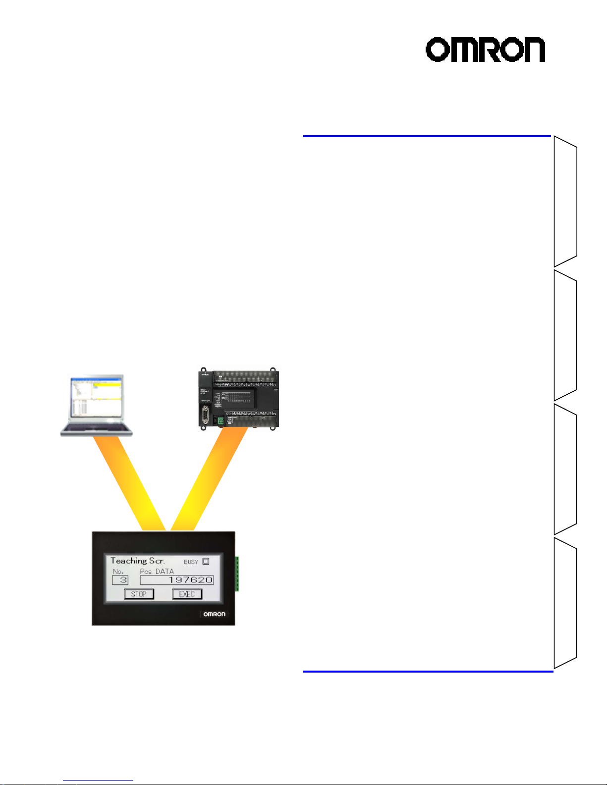
Preparation
NV-series PT
Simple Operation
Handbook
- A case of connection to a CP1E PLC -
Table of Contents
Preparation
Required Devices 2
Wiring and Connection 4
Turning on the Power 6
Displaying the NV System Menu 7
Setting the CPIE Serial Port 8
Designing Screens
Creating New Screen Data 12
Setting the NV Communications 15
Creating Switch Parts 16
Creating Lamp Parts 19
Creating Data Parts 21
Creating Keyboard Screens 23
Creating Character Stings26
Connecting with CP1E PLC
Transferring Screen Data 28
Checking Operation 31
Advanced Usage
Switching Screens from CP1E 32
Changing Backlight Colors
from CP1E 34
Connecting PC and PLC via NV 35
The NV3W-V1 is added.
Page 2
2
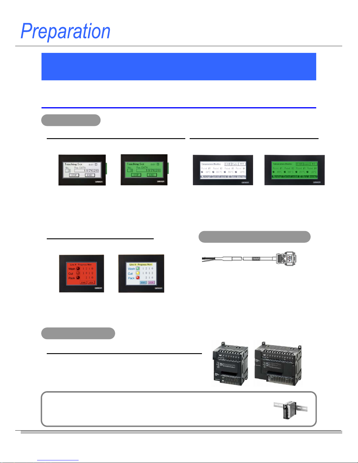
These are the devices required to connect an NV-series PT to a CP1E PLC.
Required Devices
Application Models
CP1E-NxxS1-type (built-in 3 ports), CP1E-NxxS-type (built-in 2 ports)
-RS-232C type (24 VDC) -
NV3Q-MR21 NV3Q-SW21
-RS-422A type (24 VDC) -
NV3Q-MR41 NV3Q-SW41
Power supply for Programmable Terminals
Use a 24-VDC power supply unit for an NV3W-V1 (24-VDC type), NV4W or NV3Q.
A power supply unit is not necessary for an NV3W-V1 RS-232C type (5-VDC type), since the 5-
V power is supplied from the PLC via the cable (XW2Z-200T-4).
PT: NV Series
PLC: CP1E Series
Compact Horizontal Models: NV3W-V1 (3.8 inch)
- RS-232C type (5 VDC) -
NV3W-MR20L-V1 NV3W-MG20L-V1
- RS-232C type (24 VDC) -
NV3W-MR20-V1 NV3W-MG20-V1
- RS-422A type (24 VDC) -
NV3W-MR40-V1 NV3W-MG40-V1
QVGA Models: NV3Q (3.6 inch)
Package PLCs with Exceptional Cost: CP1E
Three color LED backlight
of white, pink and red
NV3W-MRxx(x)-V1
Three color LED backlight
of green, orange and red
NV3W-MGxx(x)-V1
Three color LED backlight
of white, pink and red
NV3Q-MRxx
STN color
(Display colors: 4096 colors)
NV3Q-SWxx
-RS-232C type (5 VDC) -
XW2Z-200T-4 (2 m with 5-V Line)
-RS-232C type (24 VDC) -
XW2Z-200T-3 (2 m without 5-V Line)
XW2Z-500T-3 (5 m without 5-V Line)
-RS-422A type (24 VDC) -
Prepare one by referring to the Manual.
PT-to-PLC Connecting Cable
Compact Horizontal Models: NV4W (4.6 inch)
- RS-232C type (24 VDC) -
NV4W-MR21 NV4W-MG21
- RS-422A type (24 VDC) -
NV4W-MR41 NV4W-MG41
Three color LED backlight
of white, pink and red
NV4W-MRxx
Three color LED backlight
of green, orange and red
NV4W-MGxx
Note: E-type CP1E CPU Units (Basic Models) can not be used with an NV-series
PT, since they do not have a RS-232C port.
< Renewal type >
Page 3
NV-series PT Simple Operation Handbook
Advanced Usage
Advanced Usage
Connecting with
CPIE PLC
Designing Screens
Preparation
3
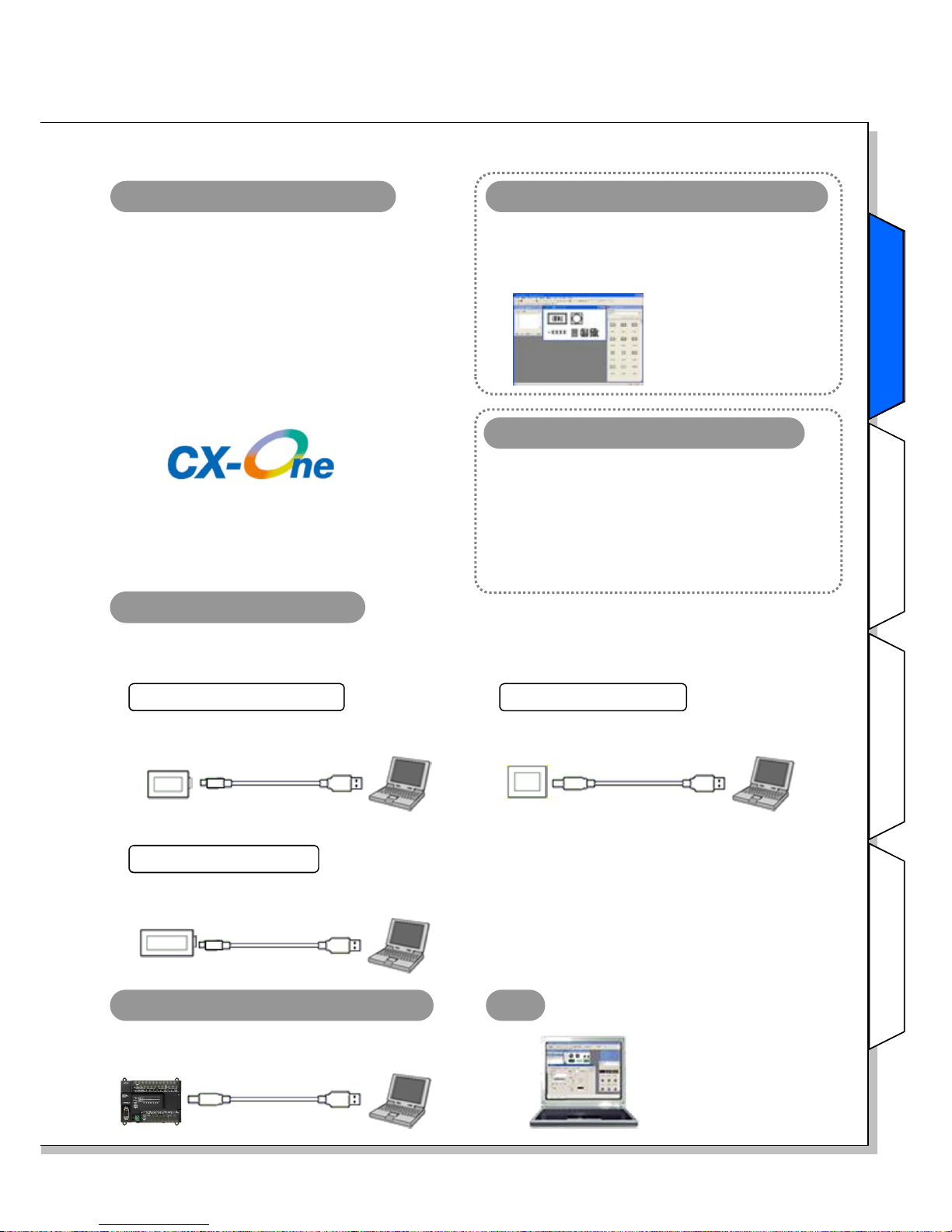
FA Integrated Tool Package
CX-One Ver.4.x (4.03 or higher)
The CX-One is a package that integrates the
Support Software for OMRON PLCs and
components.
CX-One Lite Ver.4.x (4.03 or higher)
The CX-One Lite is a subset of the complete CXOne package that provides only the Support
Software required for micro PLC applications.
Select from two packages: Included in both packages of CX-One Lite Ver.4 and CX-
One Ver.4.
* It cannot be purchased individually.
NV-Designer Ver.1.1 or higher
Screen designing software for NV
Programming software for PLC
Included in a package of CX-One Lite Ver.4.
Micro PLC Edition CX-Programmer Ver.9.
Included in a package of CX-One Ver.4.
CX-Programmer Ver.9
Select from two types of software:
NV-PC connection cable
Use a commercially available USB cable (Mini-B) to connect the NV3W-V1 or NV4W to a PC.
Use a commercially available USB cable (Type B) to connect the NV3Q to a PC.
Preparation
PC
Use a commercially available USB cable.
CP1E PLC-PC connection cable
CP1E
Type B Type A
NV4W
Connecting an NV4W
Mini-B Type A
Use a commercially available USB cable (Mini-B).
* Supporting Windows 7
(32-bit version)!
NV3Q
Connecting an NV3Q
Use a commercially available USB cable (Type B).
Type B Type A
NV3W-V1
Connecting an NV3W-V1
Mini-B Type A
Use a commercially available USB cable (Mini-B).
Note: The NV-Designer
Ver.2.0 or higher is
required to use the
NV3W-V1.
Page 4
4
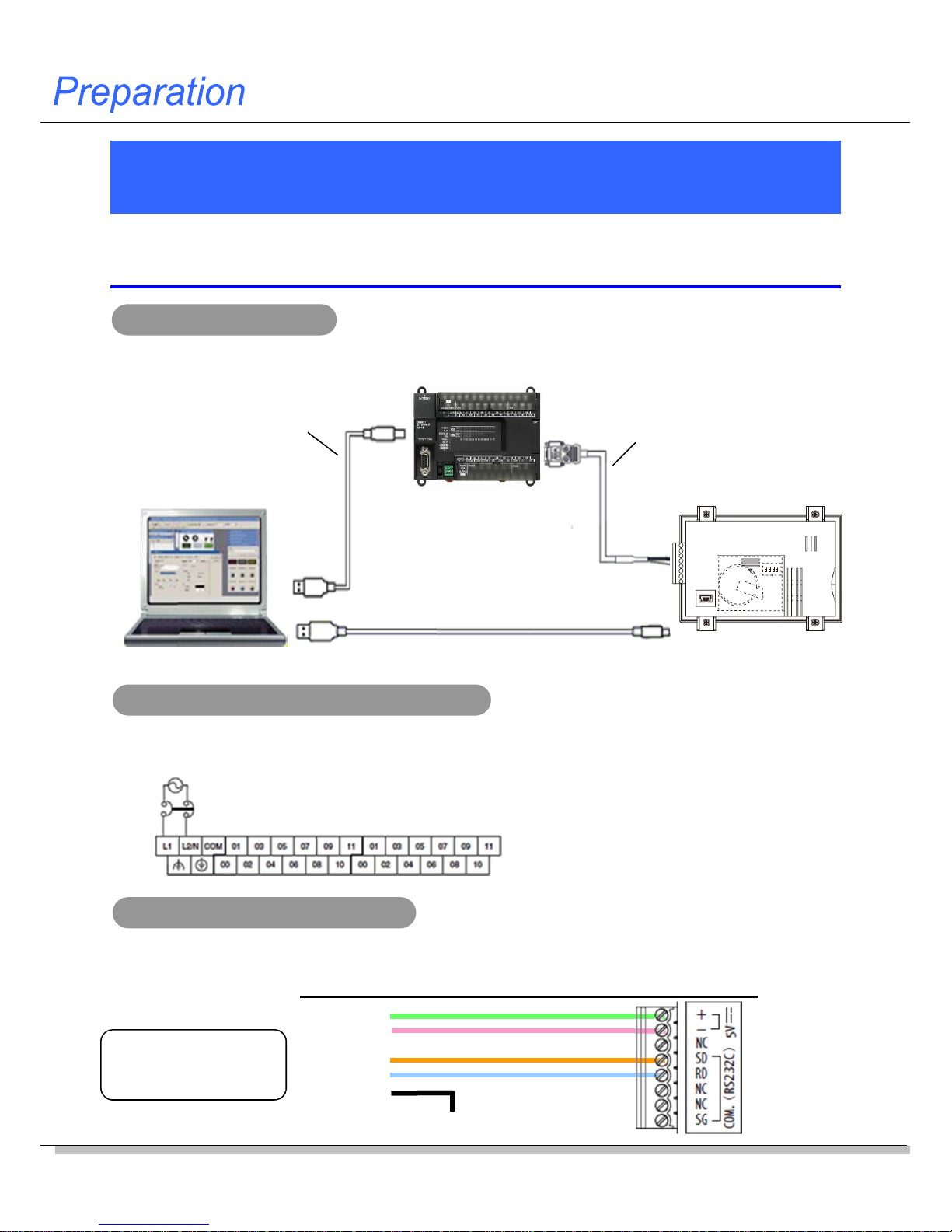
Wiring and Connection
Connect the devices.
* This section explains the procedure to connect an NV3W-V1 (5-VDC type) PT to a CP1E PLC.
Connecting example
Commercially available USB cable
(Type A connector – Type B connector)
XW2Z-200T-4
(2 m with 5-V Line)
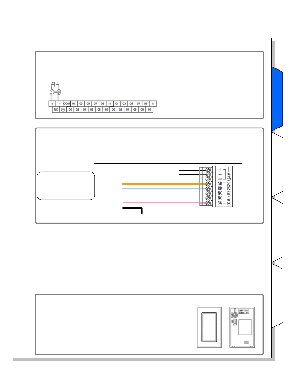
Connecting the NV and CP1E
Connecting an NV3W-V1 (5-VDC type) PT to the USB port on a PC
5 V power (green)
Name (color)
RD (orange)
SD (blue)
SG (pink)
NV3W-V1 (5-VDC)
* The NV3W-V1 (5-VDC type) does not need a pow er supp l y unit. The 5-V power is supplied from the PLC through the XW2Z-200T-4
Special Cable.
NV3W-MR20L-V1
PC
CP1E-N30SDx-x
Wiring for the CP1E AC power supply
Wire for the CP1E AC power supply.
Connect the NV and the CP1E with the XW2Z-200T-4 Special Cable.
FG (black)
Ground to 100 ohm or less
XW2Z-200T-4
Special Cable
(2 m with 5-V Line)
Upper terminal block
100 to 240 VAC, 50/60 Hz
Commercially available USB cable (Mini-B)
Page 5
NV-series PT Simple Operation Handbook
Advanced Usage
Advanced Usage
Connecting with
CPIE PLC
Designing Screens
Preparation
5
The NV3W-V1 and NV4W PTs can be mounted vertically.
Mount the PT with the serial communications/power supply
connector on top.
Using a Vertically Mounted PT (NV3W-V1 and NV4W only)
When the CP1E uses a 24-VDC power supply
Wire the 24-VDC power supply as shown below.
XW2Z-200T-3
(2 m, without 5-V Line)
XW2Z-500T-3
(5 m, without 5-V Line)
When the NV3W-V1 (24-VDC type), the NV4W, or the NV3Q is connected
with a RS-232C cable
Wire the NV and the PLC as follows. The power is supplied from the external supply unit to
the PT.
Name (color)
RD (orange)
SD (blue)
SG (pink)
NV3W-V1 (24-VDC)/NV4W/NV3Q
FG (black)
Ground to 100 ohm or less
24-VDC power supply
Upper terminal block
24-VDC power supply
Preparation
Page 6
6
Turning on the Power
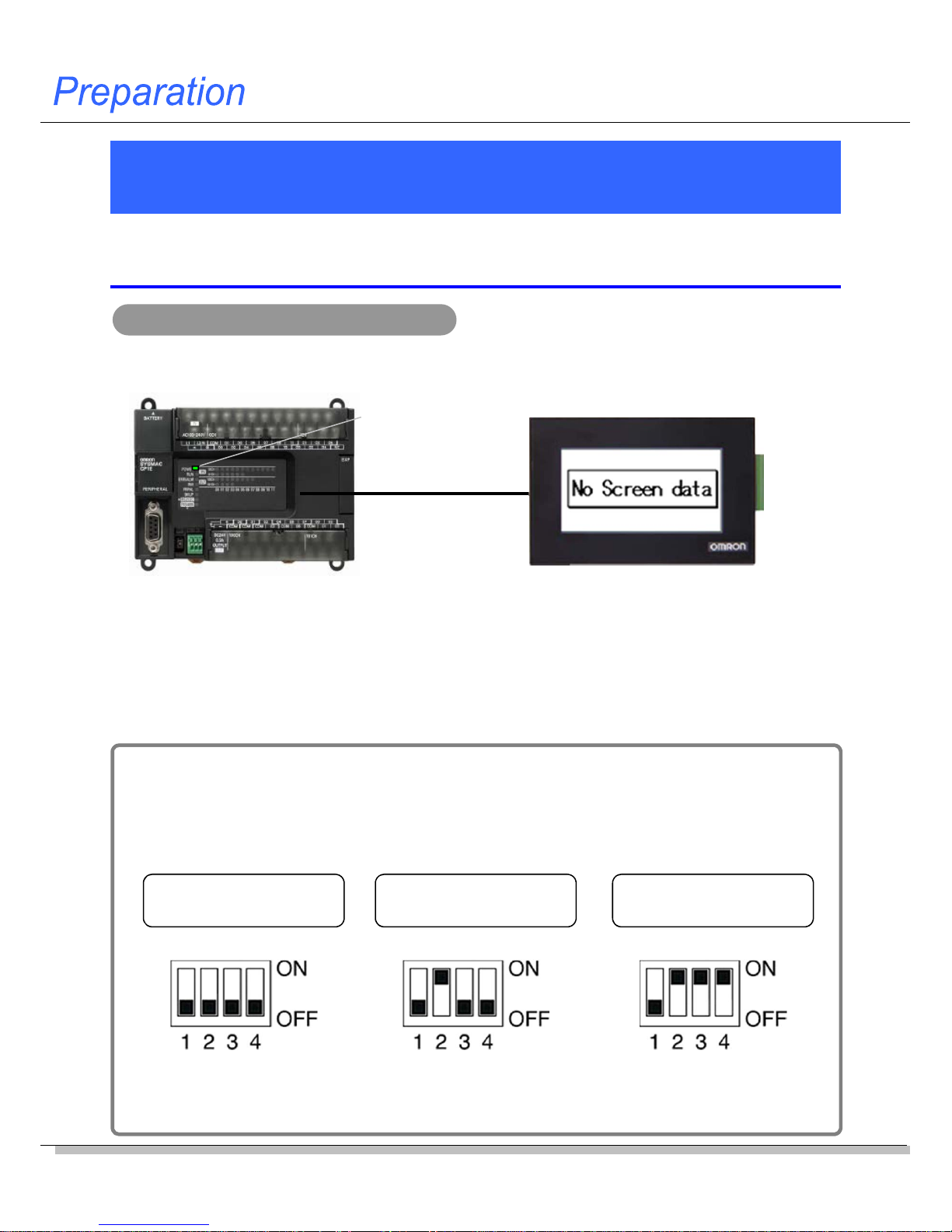
Turn on the power to the CP1E. The power is also supplied to the NV
through the RE-232C serial port on the CP1E.
If you turn ON the power to the NV after you change the DIP switch pins on the NV back face to
any setting other than default setting, the NV starts up in a special operation mode. You can use
the functions to prohibit accessing the System Menu and to clear the F-ROM.
* Do not use the NV in any settings other than shown below.
Normal operation
(default )
Prohibiting moving to
System Menu
F-ROM clear
Note 1: The data saved in the F-ROM includes screen data and NV configuration data.
Note 2: Other than the DIP switch setting, you can clear the F-ROM from the System Menu.
Turning on the power to the CP1E
NV startup mode
Turn on the power to the CP1E. The POWER LED indicator on the front of the CP1E lights in
green. The NV screen shows a message as follows:
Note: The message “No Screen data” is shown when the NV has no screen data.
As the NV contains no data at factory shipping, This message is shown accordingly.
Turn OFF all pins. Turn ON pin 2. Turn ON pins 2, 3, and 4.
POWER
LED
XW2Z-200T-4
Page 7
NV-series PT Simple Operation Handbook
Advanced Usage
Advanced Usage
Connecting with
CPIE PLC
Designing Screens
Preparation
7
Displaying the NV System Menu
The System Menu is the special screen that is used to configure the NV.
Some settings such as touch switch adjustment can only be done on the
System Menu.
Accessing the System Menu
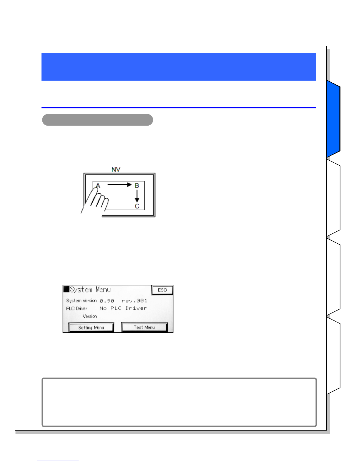
Follow the steps below to access the System Menu.
1. Touch the touch panel on the PT as shown below.
(This is common for the entire NV Series.)
1) Touch the upper left corner (A) for at least 2
seconds.
2) Then immediately touch the upper right
corner (B) and lower right corner (C) in order.
Note: Touch the points A, B, and C, one at a time in order. Do not press these points at the
same time.
2. The startup screen of the System Menu will be displayed.
The startup screen of the System Menu will be
displayed.
The next screen will be displayed if you touch
the Setting Menu or Test Menu Key.
To return to normal operating status, touch the
ESC Key.
Note: The system version is the version of the system ROM in the PT.
The default language for the System Menu is English, if there is no screen data in the PT.
The System Menu depends on the PT model. The default System Menu for the NV3W-V1
is used here.
Changing the System Menu language
The language is switchable between English and Japanese on the NV System Menu.
Select Setting Menu - Language.
Touch A for at least 2 seconds, then press B and C in order.
Preparation
Page 8
8
Setting the CP1E Serial Port
To have the NV and the CP1E communications, the both serial ports must
have the same setting. Use the PLC programming tool CX-Programmer to
set the communications on the CP1E.
Be sure to change the stop bit on the PLC from the default 2 to 1
The stop bit for the NV serial communications is fixed to 1 . Therefore, the stop bit of the
PLC serial port must be changed from the default 2 to 1.
NV-CP1E communications setting example
Both the NV and the CP1E support the high speed communication of 115,200 bps.
Connect them in this baud rate.
Set the RS-232C serial ports on both of the NV and the CP1E as follows:
Mode: Host Link
Baud rate: 115,200 bps
Data length: 7
Stop bit: 1
Parity bit: Even
Communications setting for the RS-232C serial port built in the CP1E
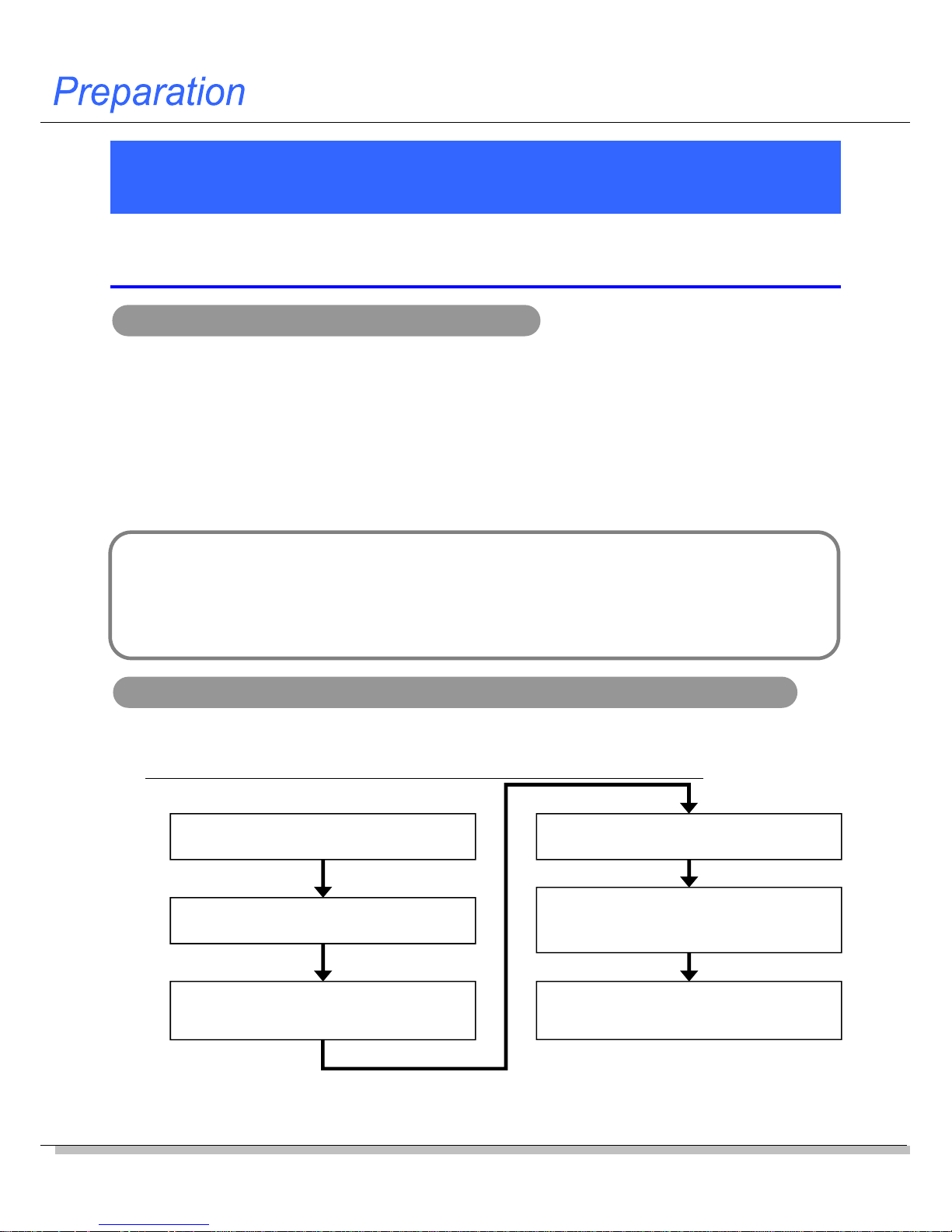
Use the PLC programming tool CX-Programmer. Follow the steps below to set the RS-232C
serial port built in the CP1E.
* After this setting is completed, turn OFF and then ON the power of the CP1E.
Connect the CX-Programmer and the
CP1E online using a USB cable.
Change the CP1E operation mode to
“Program Mode” (Stopped).
Upload the PLC settings (including the
built-in RS-232C serial port setting)
from the CP1E.
Set the built-in RS-232C serial port on
the PLC Settings.
Write the PLC settings (including the
built-in RS-232C serial port setting) into
the CP1E.
Turn OFF and then ON the power of
the CP1E. (The settings are reflected
only after the power is turned ON.)
1
2
3
4
5
6
Note: Communications may be enabled, even when the stop bit on the PLC is 2 while the bit on the NV is 1. However,
be sure to set the both to 1.
Page 9
NV-series PT Simple Operation Handbook
Advanced Usage
Advanced Usage
Connecting with
CPIE PLC
Designing Screens
Preparation
9
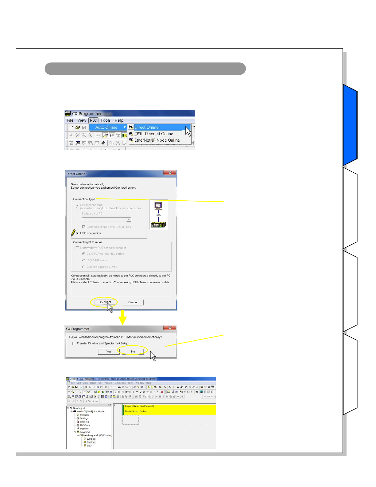
Online connection of the CX-Programmer and CP1E
1. Select Program – OMRON – CX-One – CX-Programmer – CX-Programmer from the
Windows Start Menu to start the CX-Programmer.
2. Select PLC – Auto Online – Direct Online from the menu bar.
3. In the Direct Online Dialog Box, select USB connection for the PC – PLC (CP1E)
connection type. Click the Connect Button.
Connection Type:
Select either
Serial connection or
USB connection.
1) Click the No Button.
* Click the Yes Button to upload
the program to the PC.
4. When the PC is connected with the CP1E, a new project will start.
Preparation
Page 10
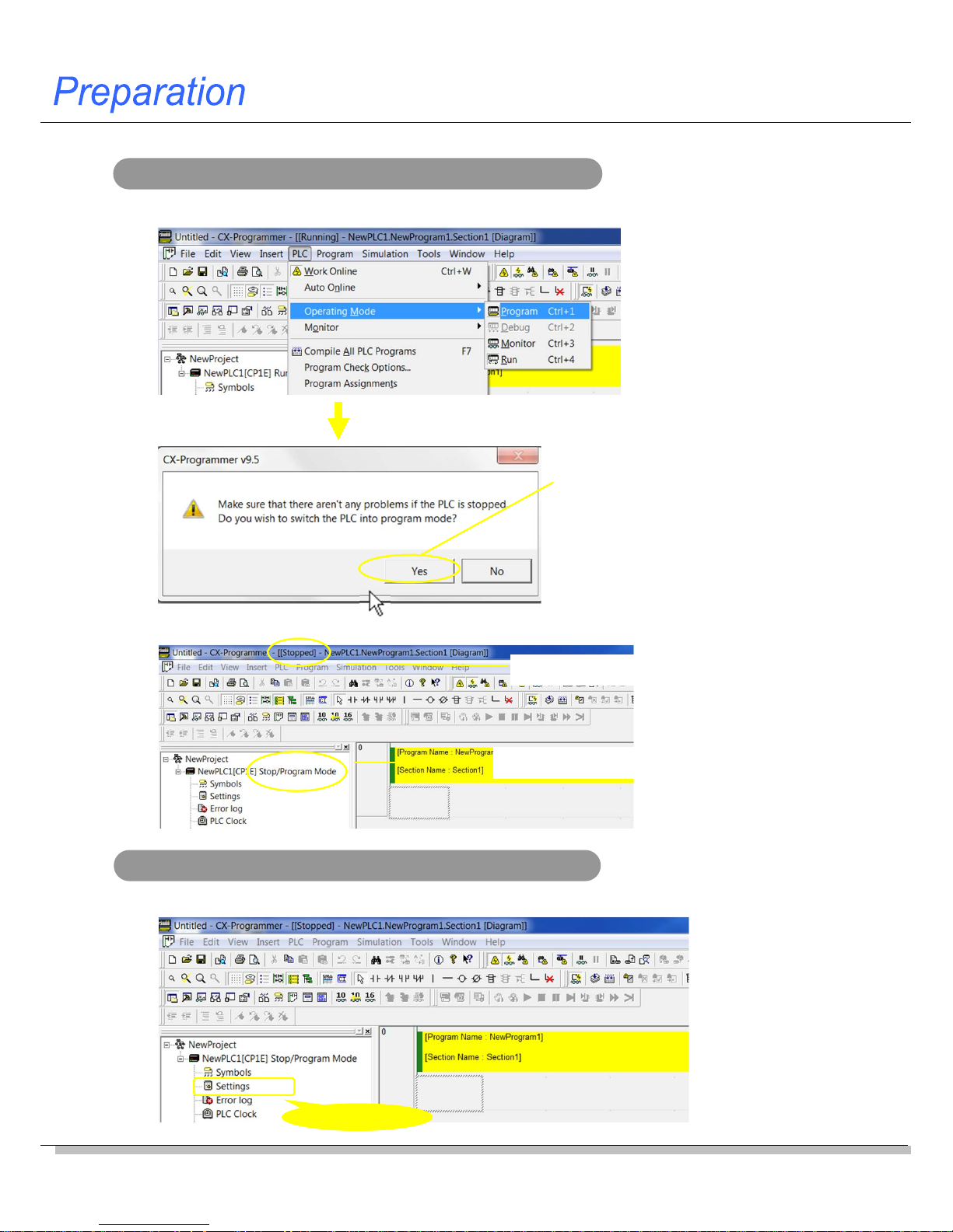
10
Changing the CP1E operation mode into Program
1. Select PLC – Operation Mode – Program from the menu bar.
1) Confirm that stopping the ladder
program do not cause any
problem. Click the Yes Button.
2. The CP1E operation mode changes to the Program Mode.
“Stopped” is displayed.
“Program Mode” is displayed.zzzzz
Transferring, setting and wr iting the PLC settings
1. Double-click Settings in the project tree.
Double-click!!
Page 11
NV-series PT Simple Operation Handbook
Advanced Usage
Advanced Usage
Connecting with
CPIE PLC
Designing Screens
Preparation
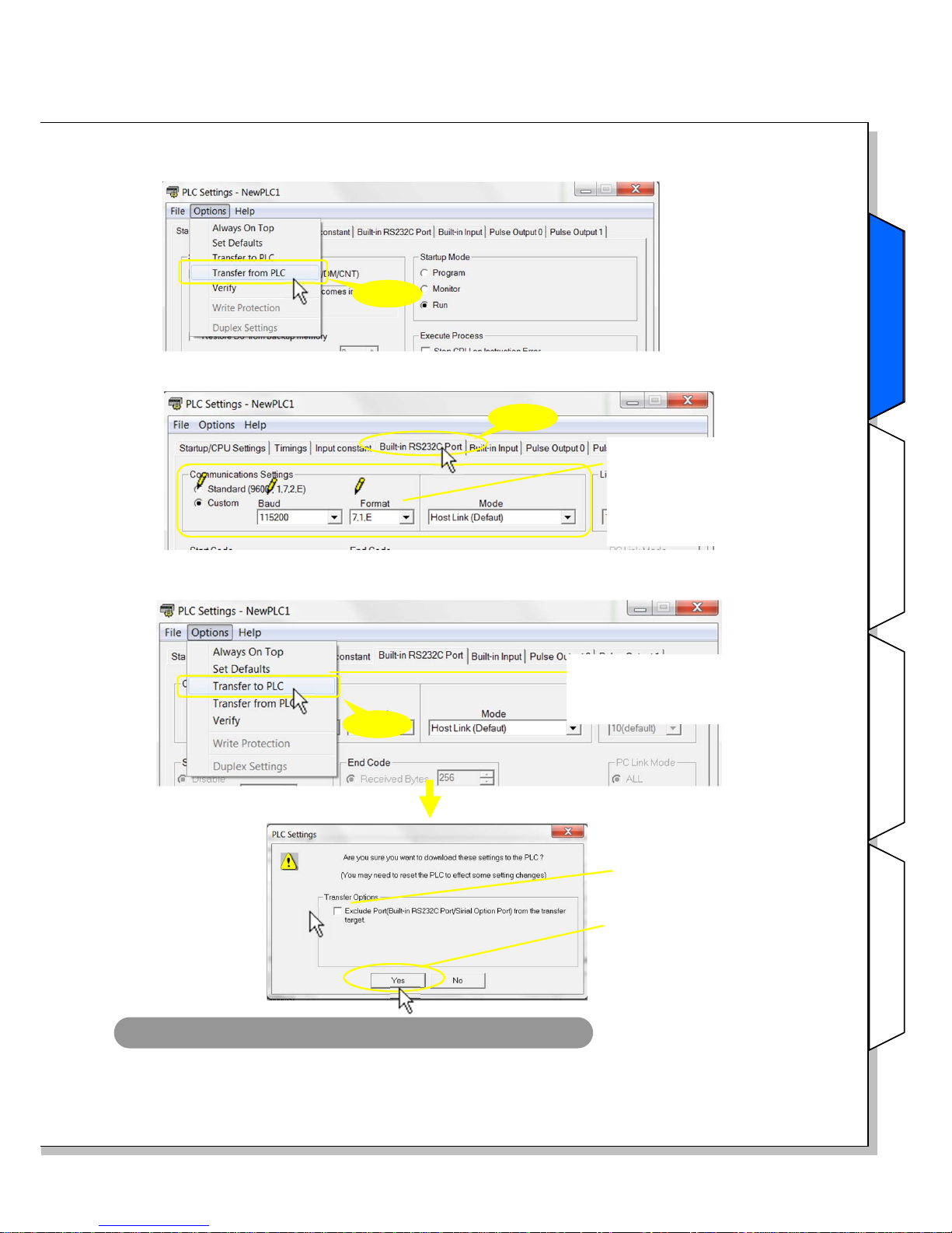
11
4. Select Options – Transfer to PLC from the menu bar.
Click!!
* It is not selectable, when the PLC
operation mode is not in Program
Mode.
1) Do not select.
2) Click the Yes Button.
2. The PLC Settings Dialog Box appears .
Select Options – Transfer from PLC from the menu bar.
* The second value from the
left of Format is the stop bit.
Be sure to set it to “1” when
the PLC is connected to an
NV.
Click!!
Click!!
3. The PLC settings for the CP1E are uploaded to the PC. Make the setting on the Built-in
RS232C Port Tab Page as follows.
Turning OFF and then ON the power of the CP1E
1. Turn OFF and then ON the power of the CP1E. The RS-232C serial port setting becomes
effective when the power is turned ON. This completes the CP1E communications setting.
Preparation
Page 12

12
Creating New Screen Data
The NV communications setting is set by transferring the screen data to the NV.
Create screen data by using the screen designing software NV-Designer.
Starting the NV-Designer and creating a new project
1. Select Program – OMRON – CX-One – NV-Designer - NV-Designer from the
Windows Start Menu,.
3. On the Select Model Dialog Box, select the NV model and the NV type and enter the project
name. Click the Next Button.
NV Model:
Select the PT model.
2. When the NV-Designer is started, the NV-Designer Dialog Box will be displayed.
Select Create New Project. Click the OK Button.
NV Type:
Select one from monochrome,
color and vertical.
File Name:
Enter a project file name. In the
left example, a file “New Project.
nvp” and a folder “New Project”
are created.
Page 13

NV-series PT Simple Operation Handbook
Advanced Usage
Advanced Usage
Connecting with
CPIE PLC
Designing Screens
Preparation
13
4. Select the PLC model to connect. Click the Next Button.
PLC Model:
Select the PLC model to
connect.
5. In the System Memory Area Field, set the Word Area and the Bit Area.
Click the OK Button.
Three consecutive words are allocated for the Word Area to read and write data in word units
such as Screen No., and three consecutive words are allocated for the Bit Area to read and write
data in bit units such as Backlight Light/Blink. In total six words are allocated.
The system memory is used for the PLC to control the basic operations such as switching
screens. The specified words in the PLC memory are allocated for communications, which are
performed constantly.
System memory
Number of w ords allocated for the system memory
System Memory Area:
Specify the areas for controlling
the NV in the PLC internal
memory.
Note: The default word for the Bit
Area is CIO 0. As CIO 0 is
allocated to the CP1E input
word, be sure to change to a
word in the Work Area.
Designing Screens
Note: The words allocated to the system memory can be changed from the menu bar.
Select PT – NV Configuration.
Page 14

14
6. The Main Window of the NV-Designer will be displayed.
Double-click “0” in the Screen Manager. Base screen 0 and the Parts Library will open.
Character strings and parts are positioned on the screen to create a base screen.
Manu bar
Toolbar
Graphic bar
Base Screen Parts LibraryScreen Manager
Base Screen
Parts Library
A parts library contains parts, such as switches, lamps, data displays, and keyboa rds.
Your own parts library can be created by registering customized parts to reuse them.
Screen Manager
Screens can be copied, pasted, cut, and deleted using the Screen Manager. Multiple projects
can be started simultaneously and editing can be performed between the Screen Managers.
Double-click!!
Size-Position
Bar
Note: The Size-Position Bar is a new function added to the NV-Designer Ver.2.0.
Page 15

NV-series PT Simple Operation Handbook
Advanced Usage
Advanced Usage
Connecting with
CPIE PLC
Designing Screens
Preparation
Setting the NV Communications
Set the NV - CP1E communications as the screen data.
Setting the NV communications
1. Select PT – NV Configuration from the menu bar.
Click!!
NV-CP1E communications setting example
The CP1E communications was set as follows. Set the same for the NV communications.
Mode: Host Link
Baud rate: 115,200 bps
Data length: 7
Stop bit: 1
Parity bit: Even
The stop bit for the NV serial communications is fixed to 1.
Therefore, the stop bit of the PLC serial port must be changed from the default 2 to 1.
2. Select the Communication Parameters Tab. Set the communications with the CP1E.
Click the OK Button to close the dialog box. This completes the NV communication setting.
Click!!
Set these items for
communications with the
CP1E.
Designing Screens
15
Page 16

16
Creating Switch Parts
This and the following few pages describe the procedure to create parts on
the screen, and confirming the NV-CP1E operations. Firstly, create a switch
part that turns ON and OFF the specified bit in the PLC.
Example of creating a switch part
CIO 10.00 in the PLC is turned ON when the switch is pressed and turned OFF when it is
released. (Momentary operation)
Normally the OFF label is displayed. While the
switch is pressed, the ON label is displayed.
Creating a switch part
Drag a switch part from the library and drop it at any desired space on the base screen.
Drag and drop!!
When pressed
When released
1) Use the Parts Library
Standard (NV3W-V1).
2) Use the part SW2.
Page 17

NV-series PT Simple Operation Handbook
Advanced Usage
Advanced Usage
Connecting with
CPIE PLC
Designing Screens
Preparation
17
Setting the function for the switch part
Double-click the switch part. Select the Basic Setup Tab. Set the Operation Mode and
ON/OFF Indication Fields.
Operation Mode:
It specifies the operation and the bit
address in the PLC.
ON/OFF Indication:
Select either On to switch the
ON/OFF indication or Off not to switch
it. When you select On, set also the
switch timing.
Creating the switch labels
1. Select the Label tab.
ON/OFF:
Set the label each when the
switch is ON and OFF.
* Click the OFF Button.
Character String:
Enter a character
string to show.
Font:
Set the front type and
the position to show
the character string.
Size:
Set the front size of
the character string.
Color:
Set the character color
and the background
color.
Designing Screens
Page 18

18
2. Click the ON Button. Click the COPY from OFF Button. Then the setting for OFF is copied to
ON. The two have the same setting.
1) ON/OFF:
Click the ON Button.
2) Click the COPY from
OFF Button.
Click!!
3. Change the character color for ON to white.
After setting, click the OK Button to close the setting dialog box. This completes creating a
switch part.
1) Change the
character color
to white.
Confirming the part ON/OFF state by preview
Select the part. Change the status between OFF and ON by the Parts State Button on the
toolbar and check the displays.
Parts State
OFF (Normal) ON (When pressed)
1) Select a part. (You
can select multiple
parts.)
2) Switch the ON/OFF
state by the Parts
State Button.
Page 19

NV-series PT Simple Operation Handbook
Advanced Usage
Advanced Usage
Connecting with
CPIE PLC
Designing Screens
Preparation
19
Creating Lamp Parts
A lamp part changes the display color when the specified bit in the PLC
turns ON and OFF.
Example of creating a lamp part
The lamp changes color depending on the ON/OFF state of CIO 10.00 in the PLC.
The lamp is white when CIO10.00 is OFF. It
turns black when CIO10.00 is turned ON.
Bit OFF
Bit ON
Creating a lamp part
Drag a lamp part from the library and drop it at any desired space on the base screen.
Drag and drop!!
Designing Screens
2) Use the part Lamp0.
1) Use the Parts Library
Standard (NV3W-V1).
Page 20

20
Setting the function for the lamp part
Double-click the lamp part. Select the Basic Setup Tab. Set the ON/OFF Bit Field. Click the OK
Button to close the dialog box. This completes creation of the lamp part.
ON/OFF Bit:
Set the bit address of the PLC.
Page 21

NV-series PT Simple Operation Handbook
Advanced Usage
Advanced Usage
Connecting with
CPIE PLC
Designing Screens
Preparation
21
Creating Data Parts
Create data parts which display the contents of addresses in the PLC on the
PT screen. Data parts can be used for indication only (no entries allowed) or
for changing the values from the keyboard screen as well.
Example of creating a data part
This data part indicates the value of D100 in the PLC in a decimal number.
The keyboard screen appears by touching the part. Enter a value on the keyboard and
change the value for D100.
Creating a data part
Drag a data part from the library and drop it at any desired space on the base screen.
1) Use the Parts Library
Standard (NV3W-V1).
2) Use the part Data.
Drag and drop!!
The screen changes to the
keyboard screen.
Enter a numeric valueTouch the part
Designing Screens
Page 22

22
Setting the function for the data part
Double-click the data part. Select the Basic Setup Tab. Make a necessary setting as shown
below. Note: This example uses the default setting.
Address:
Set the PLC word address.
Data to Display:
Set Number of Digits, Data
Format and Zero Suppression.
Note: Select ASCII for Data Format
when the data is indicated or
entered as a character string.
Setting to enable or disable input and other setting items
Click the Input Tab. Select On. Make the input settings.
Click the OK Button to lose the setting dialog box. This completes the data part setting.
Supported Keyboard:
Specify the keyboard input method.
Keyboard Screen:
Input after switching to the keyboard
screen.
Keyboard Parts:
Input from the keyboard part that is on the
same screen as the data part.
Input:
Select either On to enter values from the
screen or Off not to do it.
Note: When the Off is selected, the part is for
indication only (no entry allowed).
Startup Condition:
Select the value input timing.
Conditions
When the specified bit address satisfies
the conditions, the data part enables
inputs.
Page 23

NV-series PT Simple Operation Handbook
Advanced Usage
Advanced Usage
Connecting with
CPIE PLC
Designing Screens
Preparation
23
Creating Keyboard Screens
Create a keyboard screen to enter values for the data part.
Creating a keyboard screen
1. Select File – Keyboard Screen from the menu bar.
Click!!
2. The Edit Keyboard Screen Dialog Box will be displayed. Click [ ] 0, and then click the Draw
Button to open the keyboard screen No. 0.
Click!!
Example of creating a keyboard screen
On this keyboard screen, you can enter decimal numbers and signs. Also you can
confirm the values entered from the keyboard before they are set.
Designing Screens
Page 24

24
Creating a keyboard part
Drag a keyboard part from the library and drop it at any desired space on the keyboard screen.
1) Use the Parts Library
Standard (NV3W-V1).
3) Use the part DEC
Sign1.
Drag and drop!!
2) Click the Parts Group
Selection Button, and
then select Keyboard.
* Parts are displayed by
type.
Setting the function for the keyboard part
Double-click the keyboard part. Select the Basic Setup Tab. Make a necessary setting as
shown below. Note: This example uses the default setting.
Click the OK Button to close the dialog box.
Image:
The setting can be checked here.
Clicking a key will show the key setting dialog
box. You can change the setting for each key.
Number of Keys:
Set the vertical (column) and
horizontal (row) number of keys.
Click!!
Key Size:
Specify the size (height/width)
of keys.
Change the Keyboard:
Keyboard keys can be
selected among upper case,
lower case, and
alphanumerical + symbols.
When On is selected, specify
the keyboard number between
1 and 8.
Page 25

NV-series PT Simple Operation Handbook
Advanced Usage
Advanced Usage
Connecting with
CPIE PLC
Designing Screens
Preparation
25
Creating a data part
Place a data part to show the value entered from the screen.
Drag a data part from the library and drop it at any desired space on the keyboard screen.
1) Use the Parts Library
Standard (NV3W-V1).
3) Use the part Data.
Drag and drop!!
2) Click the Parts Group
Selection Button, and
then select Data.
Setting the function for the data part
Make a necessary setting as shown below. Note: This example uses the default setting.
Click the OK Button to close the dialog box. This completes creating a keyboard screen.
Data to Display:
Set the number of digits.
Designing Screens
Page 26

26
Creating Character Strings
This section explains the procedures to show texts or character strings on a
screen. It also describes how to change the character attributes such as
font, size and color. This way, the character string will stand out.
Example of creating a character string
In this example, the character string “Value” is outlined.
Creating a character string
1. Click the Character String Button on
the graphic bar
2. Click the position on the base screen where
you want to input a character string.
3. Enter a character string.
4. Click the Character Type Button on the
graphic bar.
5. The Character Attributes Dialog Box will be displayed. Select the Outlined Check Box.
Click the OK Button to close the setting dialog box. This completes creating a character string.
Click!!
Page 27

NV-series PT Simple Operation Handbook
Advanced Usage
Advanced Usage
Connecting with
CPIE PLC
Designing Screens
Preparation
27
To show a picture image such as bitmap on the NV screen
The NV-series PTs can display picture images such as bitmap images.
You can paste images from the Windows clipboard to the NV screens.
1. On the workspace of graphic software such as MS Paint, open an image file to show on
the NV.
2. Select the range of the image to show on the NV and copy it.
3. On the NV-Designer, open the screen to paste the image. Right-click on the screen and
select Paste from the context menu. Alternatively, press Ctrl + V to paste the image.
Right-click!!
1) Select Paste.
Note: Images that are larger than the screen (NV3W-V1: 240 x 96 (W x H), NV4W: 320 x 120 (W
x H), NV3Q: 320 x 240 (W x H) ) cannot be pasted. Scale down the image to any size
smaller than the screen before you paste it.
Designing Screens
Right-click!!
<MS Paint>
1) Select the range.
(Press Ctrl + A to select all)
2) Right-click the image, and
select Copy from the
context menu. Alternatively,
press Ctrl + C to copy the
image to the clipboard.
Page 28

28
Transferring Screen Data
Transfer the created screen data to the NV.
Setting the transfer method
1. Select PT – Transfer – Transfer from the menu bar.
Click!!
2. Select USB in the Communication Method Field. Click the OK Button to close the Transfer
Data Dialog Box.
1) Communication Method:
Select USB.
When using an NV3W
Select RS232C in the Communication Method Field.
Page 29

NV-series PT Simple Operation Handbook
Advanced Usage
Advanced Usage
Connecting with
CPIE PLC
Designing Screens
Preparation
29
Transferring the screen data
1. Set the transfer direction and data to transfer. Then transfer the data to the NV
1) Direction:
Select NV-Designer -> NV.
2) Data to Transfer:
Select the All
Data Check Box.
3) Click the OK Button to
start transferring.
The Transfer Data Dialog
Box closes.
Click!!
Use the shortcut Ctrl + T
Transfer is a frequently used operation. Use the shortcut for your convenience.
Transfer Data After Clear NV Screen:
When this check box is not selected, the NVDesigner will delete the screen data, but any
transferred data will not be deleted from the NV.
This method requires less transfer time.
When the message “Memory is full” is shown on
the screen, select this check box before
transferring the data.
Connecting with
CPIE PLC
2. When the transfer is completed, the screen is shown on the NV.
Page 30

30
“Screen No. Error” is displayed on the screen
The system memory has an area that is used to switch the NV screen from the PLC. If the
same screen No. stored in the area does not exist in the screen data, the error message
“Screen No. Error” is displayed on the screen.
As for the screen data created in this handbook, the area is allocated to D0 in the PLC.
Write “0” for the base screen 0 to D0 in the CX-Programmer.
Write “0” to D0.
Monitoring or changing the PLC parameters from the CX-Programmer
After connecting the NV and CP1E, confirm NV screen operations. This step is explained
in the next few pages. This subsection explains the Watch Window to monitor and
change the contents of PLC addresses from the CX-Programmer.
< Opening the Watch Window >
Select View –Window –Watchfrom the menu bar,
Double-click!!
Enter an address.
Enter a value.
< Monitoring the parameter values >
Double-click on the Watch Window. Enter an address to monitor.
When the PLC is connected online, the present value will be displayed.
< Changing values of addresses >
When the PLC is connected online, double-click on the line of the address in the Watch Window to
change the value.
Enter a hexadecimal value using a prefix of "#". (e.g. #1A)
Enter a decimal value using no prefix or a prefix of "&". (e.g.1234, &1234)
Specify the data type.
* The v alues cannot be changed when the PLC is in Run mode.
Change the PLC mode to Monitor (program is running) or Program (program is not executed) before changing values.
Page 31

NV-series PT Simple Operation Handbook
Advanced Usage
Advanced Usage
Connecting with
CPIE PLC
Designing Screens
Preparation
31
Checking Operation
Check operation of the parts on an actual NV.
Checking operation of the switch and lamp
1. While you press the RUN switch, 2. When you release your finger from
the RUN switch,
the lamp lights.
the lamp goes off.
Checking operation of the data part and keyboard
When you touch the data part, the keyboard screen appears. You can enter a value.
The screen changes to
the keyboard screen.
Enter a numerical value.Touch the part.
If the power supply is interrupted for longer than the I/O memory backup time, values that
the NV writes to the DM Area of the CP1E are not backed up.
The contents in the DM Area data can be backed up to the backup memory by turning ON a
bit in the Auxiliary Area.
When using a CP1E PLC without a battery
Connecting with
CPIE PLC
Page 32

32
Switching Screens from CP1E
Switch the NV screen from the CP1E PLC by using its system memory.
Creating a new screen in an existing project
Add a base screen to an existing project. The screen is used to confirm the screen
switching operation.
1. Start the NV-Designer, and open a project.
Double-click “1” in the Screen Manager. Base screen 1 will open.
Double-click!!
2. Create a character string, and enter “Base scr. 1”. Place it at the center of the screen.
Transfer the screen data to the NV.
Base screen 1
Page 33

NV-series PT Simple Operation Handbook
Advanced Usage
Advanced Usage
Connecting with
CPIE PLC
Designing Screens
Preparation
33
Setting and confirming the system memory
1. Select PT – NV Configuration from the menu bar.
Click!!
2. Click the Basic Setup Tab. In the System Memory Area Field, you can set or confirm the
allocated address.
Word area memory map (First address = N)
N: Screen number from PLC (PLCNV)
N+1: Do not use.
N+2: Current screen number (NVPLC)
Word Area:
- Screen number from PLC
This word contains the number in binary of
the screen specified by the PLC for the NV to
display.
- Current screen number
This word contains the number in binary of
the screen currently displayed by the NV.
Note: Cannot be specified in BCD.
Switching the screen from the CP1E PLC
1. Write “&0” to D0 to
display Screen 0.
2. Write “&1” to D0 to
display Screen 1.
When the screen has
been switched, “&0” is
notified to D2.
When the screen has
been switched, “&1” is
notified to D2.
On the CX-Programmer, overwrite the D0 value to switch the screens.
Advanced Usage
Advanced Usage
Page 34

34
The backlight will light in the color set in the screen properties (PT – Screen Property from
the menu bar).The backlight setting can be confirmed on the title bar of each base screen.
When the Backlight Control Enable Bit is OFF
Changing Backlight Colors from CP1E
Change the backlight color from the CP1E system memory.
* The NV3Q-SWxx (color) can be set backlight ON and OFF only.
Setting and confirming the system memory
The backlight is controlled in the Bit Area of the system memory.
Check the address allocated to the Bit Area in the System Memory Area Field on the Basic
Setup Tab Page of the NV Configuration Dialog Box.
Changing the backlight color from the CP1E
Change the values of W0.10 to W0.13 on the CX-Programmer to change the backlight status.
Set the bits for the backlight color and backlight light/blink, and then turn ON the Backlight
Control Enable Bit. (This is the example of NV3W-MGxxx-V1.)
Bit Area (First address = N)
* Backlight-related info only
N Bit10
N Bit11
N Bit12: Backlight lit (OFF)/flashing (ON)
N Bit13: Backlight Control Enable Bit
(OFF): Disables Bit10-12 settings
(ON): Enables Bit 10-12 settings
Backlight color. See the table below.
State of N Bit10 and Bit11
Bit10=OFF
Bit11=OFF
Bit10=ON
Bit11=OFF
Bit10=OFF
Bit11=ON
Bit10=ON
Bit11=ON
NV3W-MGxx(x)-V1 (Monochrome)
NV4W-MGxx (Monochrome)
Off Green Red Orange
NV3W-MRxx(x)-V1 (Monochrome)
NV4W-MRxx (Monochrome)
Off White Red Pink
NV3Q-MRxx (Monochrome) Off White Red Pink
NV3Q-SWxx (Color) Off On On On
* Backlight color specifications
Green, Light
W0.10: ON
W0.11: OFF
W0.12: OFF
W0.13: ON
Red, Blink
W0.10: OFF
W0.11: ON
W0.12: ON
W0.13: ON
(e.g. : Red, Blink)
Page 35

NV-series PT Simple Operation Handbook
Advanced Usage
Advanced Usage
Connecting with
CPIE PLC
Designing Screens
Preparation
35
Connecting PC and PLC via NV
Connect the PC and the PLC via the NV to transfer the ladder programs from
the PC (CX-Programmer) to the PLC and to monitor the PLC from the PC.
Configuration example
In this configuration, you can transfer the ladder programs and monitor the PLC from the
CX-Programmer through the NV.
PC
NV3W-V1/NV4W/NV3Q
Host Link
SYSMAC - CS / CJ / CP Series
PC connection cable
Setting
1. On the CX-Programmer, open a project of a CS, CJ or CP-series PLC.
Double-click the PLC in the project tree. The Change PLC Dialog Box will appear.
Double-click!!
2. Set Network Type to NV-Thru (USB Port). Click the OK Button.
3. Connect the PLC online.
The CX-Programmer and the NV-Designer use the same USB port. Therefore, only one of them is
online-connected with the NV at a time.
You can also connect the PLC through the NV with the CX-Programmer by selecting Auto Online -
Direct Connection from the PLC menu.
*The NV requires no setting.
Advanced Usage
Advanced Usage
Page 36

2015
0715 (0110)
V411-E1-02
 Loading...