

Omron NS series OPERATION MANUAL

Cat. No. V082-E1-09
NS-Series
Ladder Monitor
Programmable Terminals
OPERATION MANUAL
Ladder Monitor
I/O Comment Extracting Tool


Notice
OMRON products are manufactured for use according to proper procedures by a
qualified operator and only for the purposes described in this manual.
OMRON Product References
All OMRON products are capitalized in this manual. The word "Unit" is also capitalized
when it refers to an OMRON product, regardless of whether or not it appears in the
proper name of the product.
The abbreviation "Ch," which appears in some displays and on some OMRON products,
often means "word" and is abbreviated "Wd" in documentation in this sense.
The abbreviation "PLC" means Programmable Controller.
The abbreviation "host" means a controller, such as an IBM PC/AT or compatible
computer, that controls a PT (Programmable Terminal).
Visual Aids
Notice
The following headings appear in the left column of the manual to help you locate
different types of information.
Note
Reference
1, 2, 3...
CS1G-CPU@@-V1
OMRON, 2004
Indicates information of particular interest for efficient and convenient operation of
the product.
Indicates supplementary information on related topics that may be of interest to
the user.
1. Indicates lists of one sort or another, such as procedures, checklists, etc.
Boxes in model numbers indicate variable characters. For example,
"CS1G-CPU@@-EV1" indicates the following models: CS1G-CPU42-EV1,
CS1G-CPU43-EV1, CS1G-CPU44-EV1, and CS1G-CPU45-EV1.
All rights reserved. No part of this publication may be reproduced, stored in a retrieval system, or transmitted, in any form,
or by any means, mechanical, electronic, photocopying, recording, or otherwise, without the prior written permission of
OMRON.
No patent liability is assumed with respect to the use of the information contained herein. Moreover, because OMRON is
constantly striving to improve its high-quality products, the information contained in this manual is subject to change
without notice. Every precaution has been taken in the preparation of this manual. Nevertheless, OMRON assumes no
responsibility for errors or omissions. Neither is any liability assumed for damages resulting from the use of the
information contained in this publication.
1

Related Manuals
Related Manuals
The following manuals are used for NS-series PTs. (The boxes at the end of the catalog
numbers indicate the revision code.)
NS Series -V1/-V2 Setup Manual..............................................V083-E1-@
This manual describes installation and connection procedures, general
specifications, and other hardware information for NS-V1/V2-series PTs (NS15-V2,
NS12-V1/V2, NS10-V1/V2, NS8-V1/V2, and NS5-V1/V2).
Refer to the NS Series Programming Manual (V073-E1-@) for information on PT
functions and specific operating procedures.
NS Series Setup Manual...........................................................V072-E1-@
Provides information on NS Series PTs prior to V1 (i.e., NS12, NS10, and NS7).
Describes how to connect the PT to the host and peripheral devices, methods to
setup communications and operation, and procedures for maintenance.
Refer to the NS Series Programming Manual (V073-E1-@) for information on PT
functions and specific operating procedures.
NS Series Programming Manual..............................................V073-E1-@
Describes the screen configurations, object functions, and host communications for
the PT.
CX-Designer User’s Manual.....................................................V099-E1-@
The screens displayed on the PT can be created in the CX-Designer and
transferred between the CX-Designer and PT. This manual describes the
installation and features of the CX-Designer. For details on CX-Designer
operations, refer to the CX-Designer’s Online Help.
2

Terminology
Terminology
The following terminology is used in this manual.
PT In this manual, indicates an NS-series Programmable Terminal.
NS Series
PLC Indicates a Programmable Controller in the OMRON SYSMAC CS/CJ Series of
CS/CJ Series Indicates Programmable Controllers in the OMRON SYSMAC CS/CJ Series of
Serial Communications Unit Indicates a Serial Communications Unit for an OMRON CS/CJ-series PLC.
Serial Communications Board Indicates a Serial Communications Board for an OMRON CS/CJ-series PLC.
CPU Unit Indicates a CPU Unit in the OMRON SYSMAC CS/CJ Series of Programmable
CX-Designer
Host Indicates the PLC, IBM PC/AT or compatible computer, or personal computer
Programming Manual
Indicates products in the OMRON NS@@ Series of Programmable Terminals.
Programmable Controllers.
Programmable Controllers: CS1G, CS1H, CS1G-H, CS1H-H, CJ1G, CJ1G-H,
CJ1H-H, CJ1M, CP1H, CP1L, CJ2H.
In this manual, “CJ1H-H” indicates the CJ1H-CPU@@H-R and CJ1H-CPU@@H
CPU Units. “CJ1H-H-R” is used to indicate only the CJ1H-CPU @@H-R CPU Units.
The “CP Series” is used to indicate only the CP1H and CP1L.
Controllers.
Indicates the OMRON CX-Designer (NS-CXDC1-V@).
functioning as the control device and interfaced with the NS-series PT.
Indicates the NS Series Programming Manual (V073-E1-@).
3

Introduction
Introduction
Intended Audiences
•
This manual is intended for the following personnel, who must also have knowledge of
electrical systems (an electrical engineer or the equivalent).
• Personnel in charge of introducing FA systems into production facilities.
• Personnel in charge of designing FA systems.
• Personnel in charge of installing and connecting FA systems.
• Personnel in charge of managing FA systems and facilities.
General Precautions
•
• This manual provides information for connecting and setting up an NS-series PT. Be
sure to read this manual before attempting to use the PT and keep this manual close
at hand for reference during installation and operation.
4

Read and Understand this Manual
Please read and understand this manual before using the product. Please consult your OMRON
representative if you have any questions or comments.
Warranty and Limitations of Liability
WARRANTY
OMRON's exclusive warranty is that the products are free from defects in materials and workmanship for a
period of one year (or other period if specified) from date of sale by OMRON.
OMRON MAKES NO WARRANTY OR REPRESENTATION, EXPRESS OR IMPLIED, REGARDING
NON-INFRINGEMENT, MERCHANTABILITY, OR FITNESS FOR PARTICULAR PURPOSE OF THE
PRODUCTS. ANY BUYER OR USER ACKNOWLEDGES THAT THE BUYER OR USER ALONE HAS
DETERMINED THAT THE PRODUCTS WILL SUITABLY MEET THE REQUIREMENTS OF THEIR
INTENDED USE. OMRON DISCLAIMS ALL OTHER WARRANTIES, EXPRESS OR IMPLIED.
LIMITATIONS OF LIABILITY
OMRON SHALL NOT BE RESPONSIBLE FOR SPECIAL, INDIRECT, OR CONSEQUENTIAL DAMAGES,
LOSS OF PROFITS OR COMMERCIAL LOSS IN ANY WAY CONNECTED WITH THE PRODUCTS,
WHETHER SUCH CLAIM IS BASED ON CONTRACT, WARRANTY, NEGLIGENCE, OR STRICT
LIABILITY.
In no event shall the responsibility of OMRON for any act exceed the individual price of the product on
which liability is asserted.
IN NO EVENT SHALL OMRON BE RESPONSIBLE FOR WARRANTY, REPAIR, OR OTHER CLAIMS
REGARDING THE PRODUCTS UNLESS OMRON'S ANALYSIS CONFIRMS THAT THE PRODUCTS
WERE PROPERLY HANDLED, STORED, INSTALLED, AND MAINTAINED AND NOT SUBJECT TO
CONTAMINATION, ABUSE, MISUSE, OR INAPPROPRIATE MODIFICATION OR REPAIR.
5

Application Considerations
SUITABILITY FOR USE
OMRON shall not be responsible for conformity with any standards, codes, or regulations that apply to the
combination of products in the customer's application or use of the products.
At the customer's request, OMRON will provide applicable third party certification documents identifying
ratings and limitations of use that apply to the products. This information by itself is not sufficient for a
complete determination of the suitability of the products in combination with the end product, machine,
system, or other application or use.
The following are some examples of applications for which particular attention must be given. This is not
intended to be an exhaustive list of all possible uses of the products, nor is it intended to imply that the
uses listed may be suitable for the products:
• Outdoor use, uses involving potential chemical contamination or electrical interference, or conditions or
uses not described in this manual.
• Nuclear energy control systems, combustion systems, railroad systems, aviation systems, medical
equipment, amusement machines, vehicles, safety equipment, and installations subject to separate
industry or government regulations.
• Systems, machines, and equipment that could present a risk to life or property.
Please know and observe all prohibitions of use applicable to the products.
NEVER USE THE PRODUCTS FOR AN APPLICATION INVOLVING SERIOUS RISK TO LIFE OR
PROPERTY WITHOUT ENSURING THAT THE SYSTEM AS A WHOLE HAS BEEN DESIGNED TO
ADDRESS THE RISKS, AND THAT THE OMRON PRODUCTS ARE PROPERLY RATED AND
INSTALLED FOR THE INTENDED USE WITHIN THE OVERALL EQUIPMENT OR SYSTEM.
PROGRAMMABLE PRODUCTS
OMRON shall not be responsible for the user's programming of a programmable product, or any
consequence thereof.
6

Disclaimers
CHANGE IN SPECIFICATIONS
Product specifications and accessories may be changed at any time based on improvements and other
reasons.
It is our practice to change model numbers when published ratings or features are changed, or when
significant construction changes are made. However, some specifications of the products may be changed
without any notice. When in doubt, special model numbers may be assigned to fix or establish key
specifications for your application on your request. Please consult with your OMRON representative at any
time to confirm actual specifications of purchased products.
DIMENSIONS AND WEIGHTS
Dimensions and weights are nominal and are not to be used for manufacturing purposes, even when
tolerances are shown.
PERFORMANCE DATA
Performance data given in this manual is provided as a guide for the user in determining suitability and
does not constitute a warranty. It may represent the result of OMRON's test conditions, and the users must
correlate it to actual application requirements. Actual performance is subject to the OMRON Warranty and
Limitations of Liability.
ERRORS AND OMISSIONS
The information in this manual has been carefully checked and is believed to be accurate; however, no
responsibility is assumed for clerical, typographical, or proofreading errors, or omissions.
7
Safety Precautions
Safety Precautions
Notation Used for Safety Information
The following notation is used in this manual to provide precautions required to ensure
safe usage of the product.
The safety precautions that are provided are extremely important to safety.
Always read and heed the information provided in all safety precautions.
The following notation is used.
Indicates a potentially hazardous situation which, if not avoided, will
! WARNING
! Caution
Symbols
result in minor or moderate injury, or may result in serious injury or
death. Additionally there may be significant property damage.
Indicates a potentially hazardous situation which, if not avoided,
may result in minor or moderate injury, or property damage.
Prohibition
Indicates a general prohibition
Caution
Indicates general cautionary, warning, or danger level information
! WARNING
Always ensure that the personnel in charge confirm that installation,
inspection, and maintenance were properly performed for the PT.
“Personnel in charge” refers to individuals qualified and responsible for
ensuring safety during machine design, installation, operation,
maintenance, and disposal.
Ensure that installation and post-installation checks are performed by
personnel in charge who possess a thorough understanding of the
machinery to be installed.
Do not use the input functions of the PT, such as the function switches or
switches on the touch panel, in applications that involve human life, in
applications that may result in serious injury, or for emergency stop
switches.
Do not attempt to disassemble, repair, or modify the PT. Doing so may
impair the safety functions.
Do not attempt to take the Unit apart and do not touch any internal parts
while the power is being supplied. Doing either of these may result in
electrical shock.
8

Safety Precautions
! Caution
Turn OFF the +5 V power supply before connecting or disconnecting
the RS-232C cable. The +5 V circuit in the RS-232C equipment may be
destroyed by the inrush current from the conversion unit.
9

Precautions for Safe Use
Precautions for Safe Use
• When unpacking the Units, check carefully for any external scratches or other
damage. Also, shake the Units gently and check for any abnormal sound.
• The PT must be installed in a control panel.
• The mounting panel must be between 1.6 and 4.8 mm thick. Tighten the Mounting
Brackets evenly to a torque of between 0.5 and 0.6 N·m to maintain water and dust
resistance. Make sure the panel is not dirty or warped and that it is strong enough to
hold the Units.
• Do not let metal particles enter the Units when preparing the panel.
• Do not connect an AC power supply to the DC power input terminals.
• Use a DC power supply with minimal voltage fluctuation that provides a stable output
even if the power supply input is interrupted for 10 ms. The DC power supply must
also have reinforced or double insulation.
Rated power supply voltage: 24 VDC (Allowable range: 20.4 to 27.6 VDC)
Capacity: NS15: 45 W min.
NS12, NS10, or NS8: 25 W min.
• Do not perform a dielectric voltage test.
• Use a twisted-pair cable with a cross-sectional area of at least 2 mm
power terminals and always use M3.5 crimp terminals. Tighten the terminal screws to
a torque of 0.8 N·m. Make sure the screws are properly tightened.
• Ground the Unit correctly to prevent operational errors caused by noise.
• Do not touch the surface of the circuit board or the components mounted on it you’re
your bare hands. Discharge any static electricity from your body before handling the
board.
• Confirm that the current capacity of the connected device is 250 mA or less before
using the 5-V power supply from pin 6 of the RS-232C connector. The 5-V output from
the PT is 250 mA max. at 5 V ±5%.
• Turn OFF the power supply before connecting or disconnecting cables.
• Always tighten the connector screws after connecting communications cables.
• The maximum tensile load for cables is 30 N. Do not apply loads greater than this.
• Confirm the safety of the system before turning ON or OFF the power supply or before
pressing the reset button.
• The whole system may stop depending on how the power supply is turned ON or OFF.
Turn ON or OFF the power supply according to the specified procedure.
• After changing the settings of the DIP switch, always turn the power supply OFF and
ON or reset the PT.
• Do not perform the following operations while the Memory Card is being accessed:
• Turning OFF the power supply to the PT
• Pressing the PT’s reset switch
• Removing the Memory Card
• Do not remove the Memory Card while power is being supplied to it. Always follow the
specified procedure when removing the Memory Card.
• To ensure system safety, incorporate a program that periodically calls PT operation
bits from the host side to check that the PT is properly operating.
• Start actual system application only after sufficiently checking screen data, macros,
and the operation of the program in the host.
• Do not press a touch switch with a force greater than 30 N.
• Do not operate a touch switch using a screwdriver or other tool.
• Confirm the safety of the system before pressing a touch switch. Do not press touch
2
to connect to the
10

Precautions for Safe Use
switches consecutively without pausing in between. If touch switches are pressed
consecutively at high speed, the PT may not be able to detect the inputs. Confirm that
the PT has detected the input of a touch switch before pressing any other touch
switch.
• Do not accidentally press touch switches when the backlight is not lit or when the
display does not appear. Confirm the safety of the system before pressing touch
switches.
• To ensure safety when using numeral input functions, set the upper and lower limits
for the input value.
• Before initializing screen data, confirm that existing data is backed up at the
CX-Designer.
• When changing the password with the system menu, do not reset or turn OFF the
power supply until writing is finished.
• When using the device monitor or the Ladder Monitor, confirm the safety of the system
before performing the following operations.
• Changing monitor data
• Changing operation modes
• Forced setting or resetting
• Changing present values or set values
If unspecified persons may start the Ladder Monitor, use a password to prevent
incorrect operation. Refer to 3-14 Using a Password for details on the password
function.
• Dispose of any battery that has been dropped on the floor or otherwise subjected to
excessive shock.
• Do not connect an USB connector to any device that is not applicable.
• Before connecting an USB connector to a device, make sure that the device is free of
damage.
• Commercially available USB hubs and the recommended USB hub do not necessarily
have the same general specifications as the PT, and may not function properly if used
in environments subject to static electricity or other forms of noise. When using a USB
hub, take sufficient measures to prevent static electricity and other forms of noise, or
do not install the PT in an environment subject to such noise.
• Do not perform the following operations while downloading or uploading screen data
or system program. Doing so may corrupt the screen data or system program.
• Turning OFF the power supply to the PT
• Pressing the PT’s reset switch
• When mounting the Battery, be sure to use the correct Battery and mount it correctly.
• Do not disassemble or short-circuit the battery.
• Dispose of the Units and batteries according to local ordinances as they apply.
• Never use volatile solvents, such as benzene or thinners, or chemical dusters to clean
the PT.
• The backlight in the NS-series PT contains mercury. Do not dispose of the PT
together with waste to be processed at disposal plants. Dispose of the PT according to
all local laws, regulations, and ordinances.
• The backlight in the PT cannot be replaced by the user. Contact your OMRON
representative for backlight replacement.
• Periodically check the installation conditions in applications where the PT is subject to
contact with oil or water.
11

Precautions for Correct Use
Precautions for Correct Use
• Do not install the Unit in the following places:
• Locations subject to severe changes in temperature.
• Locations subject to direct sunlight
• Locations subject to temperatures or humidity outside the range specified in the
specifications
• Locations subject to condensation as the result of high humidity
• Locations subject to corrosive or flammable gases
• Locations subject to shock or vibration
• Outdoor locations directly subject to wind or rain
• Locations subject to strong ultraviolet light
• Take appropriate and sufficient countermeasures when installing systems in the
following locations:
• Locations subject to static electricity or other forms of noise
• Locations subject to strong electromagnetic fields
• Locations close to power supplies
• Locations subject to possible exposure to radioactivity
12

NS Series Ladder Monitor
OPERATION MANUAL
LADDER MONITOR

Table of Contents
Table of Contents
NS SERIES LADDER MONITOR .............................................................................................................. 13
SECTION 1 INTRODUCTION .................................................................................................................... 17
1-1
OVERVIEW AND FEATURES ......................................................................................................... 18
1-1-1 Overview .......................................................................................................................... 18
1-1-2 Features ........................................................................................................................... 18
1-1-3 Functions Added in Version 2.0....................................................................................... 19
1-1-4 Functions Added in Version 2.7....................................................................................... 19
1-1-5 Functions Added in Version 2.8....................................................................................... 19
1-1-6 Functions Added in Version 2.9....................................................................................... 20
1-1-7 Functions Added in Version 3.0....................................................................................... 20
1-1-8 Functions Added in Version 3.1....................................................................................... 21
1-1-9 Functions Added in Version 3.2....................................................................................... 21
1-2 CHECKING THE PACKAGE ........................................................................................................... 22
1-3 MEMORY CARDS........................................................................................................................ 24
1-4 SPECIFICATIONS ........................................................................................................................ 25
1-5 SYSTEM CONFIGURATION ........................................................................................................... 27
SECTION 2 INSTALLATION ..................................................................................................................... 29
2-1
STARTING THE LADDER MONITOR ............................................................................................... 30
2-2 EXITING LADDER MONITOR ......................................................................................................... 40
SECTION 3 BASIC OPERATION .............................................................................................................. 41
3-1
MAIN SCREEN ............................................................................................................................ 42
3-1-1 Ladder Display Area ........................................................................................................ 42
3-1-2 Multiple I/O Monitor Area ................................................................................................. 45
3-1-3 I/O Comment Display Area and Error Display Area ........................................................ 45
3-1-4 Button Area ...................................................................................................................... 46
3-1-5 Inputting Addresses and Numbers .................................................................................. 47
3-2 QUICK REFERENCE .................................................................................................................... 49
3-3 DISPLAYING THE DESIRED PROGRAM SECTION ............................................................................ 51
3-3-1 Searching for Step Numbers............................................................................................ 52
3-3-2 Searching for Specified Addresses.................................................................................. 52
3-3-3 Searching for Specified Addresses Used for Sequence Output Instructions .................. 53
3-3-4 Searching for Specified Instructions ................................................................................ 54
3-3-5 Searching for the Address at the Cursor Position ........................................................... 55
3-3-6 Searching for Output Instructions from Input Bits............................................................ 56
3-3-7 Searching for Input Bits from Output Instructions............................................................ 57
3-3-8 Returning to Previous Search Positions .......................................................................... 57
3-3-9 Displaying the Previous/Next Program Section ............................................................... 57
3-3-10 Displaying Hidden Program Lines ................................................................................... 57
3-3-11 Jumping from a PT User Screen to Where an Alarm Occurs.......................................... 58
3-3-12 Back Searching................................................................................................................ 61
3-3-13 Search-related Settings ................................................................................................... 62
14

Table of Contents
3-4 DISPLAYING I/O COMMENTS ....................................................................................................... 64
3-4-1 Displaying I/O Comments ................................................................................................ 64
3-4-2 Switching the I/O Comment Display ................................................................................ 65
3-4-3 Displaying the Entire I/O Comment ................................................................................. 65
3-5 MONITORING I/O STATUS ........................................................................................................... 67
3-5-1 Monitoring I/O Status ....................................................................................................... 67
3-5-2 Stopping I/O Status Monitoring........................................................................................ 67
3-5-3 Changing the Present Value Display Format .................................................................. 68
3-6 MULTIPLE I/O MONITORING ........................................................................................................ 69
3-6-1 Specifying the I/O to Monitor ........................................................................................... 69
3-7 CHANGING ADDRESS STATUS/CONTENTS ................................................................................... 71
3-7-1 Force-setting/Resetting or Setting/Resetting Specified Bits............................................ 71
3-7-2 Cancelling Forced Status for All Bits ............................................................................... 72
3-7-3 Changing Present Values of Specified Words................................................................. 74
3-8 CHANGING TIMER/COUNTER SET VALUES
3-9 CHANGING THE PLC OPERATING MODE...................................................................................... 79
3-10 DISPLAYING CURRENT ERRORS IN THE PLC................................................................................ 80
3-10-1 Clearing Current Errors in the PLC.................................................................................. 81
3-11 CAPTURING SCREENS ................................................................................................................ 82
3-12 STARTING THE PROGRAMMING CONSOLE .................................................................................... 84
3-12-1 Ports That Support the Programming Console Function................................................. 84
3-12-2 Starting the Programming Console Function................................................................... 85
3-12-3 Prohibiting Programming Console Startup ...................................................................... 87
3-13 CHANGING THE HOST (PLC) ...................................................................................................... 88
3-14 USING A PASSWORD .................................................................................................................. 89
................................................................................... 76
SECTION 4 TROUBLESHOOTING........................................................................................................... 91
4-1
TROUBLESHOOTING ................................................................................................................... 92
4-1-1 Ladder Monitor Does Not Start ........................................................................................ 92
4-1-2 FINS Command and System File Error Messages ......................................................... 92
4-1-3 Operation, Input, and Other Error Messages .................................................................. 95
4-1-4 Error Message When Using Programming Console Function ........................................ 97
APPENDICES ............................................................................................................................................ 99
A-1
COMPARISON BETWEEN NS-SERIES PTS AND CX-PROGRAMMER .............................................. 100
A-1-1 Ladder Program Display ................................................................................................ 100
A-1-2 Monitoring I/O Status of Ladder Program...................................................................... 101
A-1-3 Search Program Section Function................................................................................. 101
A-1-4 Multiple I/O Monitor........................................................................................................ 102
A-2 STANDARD MODELS
................................................................................................................. 103
15


Section 1
Introduction

1-1 Overview and Features
1-1-1 Overview
1-1 Overview and Features
1-1-1 Overview
The Ladder Monitor (NS-EXT01) is an application that monitors the ladder program in a
SYSMAC CS/CJ-series PLC. The Ladder Monitor enables monitoring the execution
status of the ladder program in a connected PLC from a NS-series PT without using a
Programming Device (e.g., the CX-Programmer or a Programming Console). Just by
switching to the Ladder Monitor from RUN Mode of the PT, the user can monitor the
ladder program and I/O in the PLC without changing the system configuration between
the NS-series PT and the PLC.
Just connect the NS-series PT to a CS/CJ-series PLC with a 1:N NT link, an Ethernet
connector, or a Controller Link connection to a registered host, download the project data
to the PT, place a Memory Card containing the Ladder Monitor program in the PT, and
select Ladder Monitor from the system menu of the PT. The application will start, will
monitor the ladder program and I/O of the PLC, and will display the results on the
NS-series PT screen.
Note: The Ladder Monitor only monitors the ladder program. It does not have functionality to
change or edit the program. (Force-setting/resetting bits, changing present values, and
changing timer/counter set values are enabled for the I/O memory.) In addition, I/O
comments can be displayed but symbol names cannot be displayed. Refer to Appendix A-1
Comparison between NS-series PTs and CX-Programmer (page 100) for the differences
from CX-Programmer.
Note: The following PT functions will stop when the Ladder Monitor is used.
• System memory communications with the host
• Macros
• Data log
• Alarms
• Operation log
1-1-2 Features
1. The user program can be displayed in ladder form on an NS-series PT (up to 17 rows
and 16 columns for the NS12).
2. CS/CJ-series PLCs and NSJ Controllers can be monitored. A CS/CJ-series PLC that
is connected to either serial (RS-232C) port A or B of the PT in 1:N NT Link serial
communications mode or a PLC connected to the Ethernet port or Controller Link
Board of the PT can be monitored.
3. The bit ON/OFF status (i.e., the execution conditions) and present values (words) of
the operands of special instructions can be monitored.
4. The desired program section can be specified using the Search Button.
Searching is possible for step numbers (program addresses), instructions (selected
from a list, including immediate refreshing and differentiation), and instructions with
addresses.
5. Jumping from an input bit (“contact”) to the output instruction with the same address
(i.e., to a sequence output instruction) is possible (JUMP Search). By repeating this,
it is also possible to identify the input bits causing outputs to turn ON and OFF.
6. It is possible to search for input bits that are using the address in an output
instruction.
18

1-1 Overview and Features
1-1-3 Functions Added in Version 2.0
7. In addition to searching for output instructions from input bits and input bits from
output instructions, it is also possible to return to the results of up to 30 previous
searches.
8. With NS-series PT system version 8.0 or higher, the places where an address
specified as an alarm is used can be automatically found by starting the Ladder
Monitor from the Alarm/Event Summary and History on the PT screen.
9. The Multiple I/O Monitor operation can be used to monitor up to 20 (for the NS15)
specified addresses (bits or words).
10. Force-setting/resetting or setting/resetting of a specified bit address can be
performed on the Multiple I/O Monitor Screen.
11. The present value of a specified word address can be changed.
12. Word present values can be displayed and input in hexadecimal, decimal, or signed
decimal.
13. Timer and counter set values can be changed.
14. The operating mode of the PLC (CPU Unit) can be changed.
15. Current errors (non-fatal errors and fatal errors) in the PLC (CPU Unit) can be
displayed. Errors can also be cleared.
16. I/O comments can be read from the PLC. If the I/O comments have been changed,
the change will be automatically detected when the Ladder Monitor is started, and it
can be selected whether the I/O comments are to be read from the PLC.
17. I/O comments can be displayed in three lines or one line, or not displayed at all. A
maximum of five characters can be displayed per line. In addition, comments for
addresses selected on the screen can be displayed at the bottom of the screen (up to
71 characters for the NS15, 43 characters for the NS12, or 23 characters for the
NS10/8).
18. Ladder Monitor screens can be captured and saved on Memory Cards as bit map
files.
1-1-3 Functions Added in Version 2.0
The following functions have been added for Ladder Monitor version 2.
1. Programming Console Function for CS/CJ-series PLCs
The ladder program can be changed, such as changing/adding input bits and
changing set values.
2. Binary TIM/CNT instructions can be monitored on the ladder diagram.
3. Pulse control instructions, interrupt instructions, and table comparison instructions,
which were added for the CJ1M PLCs, can be monitored using ladder diagrams.
4. Duplex error messages can be displayed for CS1D (Duplex System) PLCs.
5. The following function was added in version 2.5:
Operation support for NS-V1 Series PTs.
1-1-4 Functions Added in Version 2.7
The following functions have been added for Ladder Monitor version 2.7.
An Ethernet or Controller Link port can be used to connect to the PLC.
1-1-5 Functions Added in Version 2.8
The following functions have been added for Ladder Monitor version 2.8.
• The Ladder Monitor has been built into the system program for version-2 NS-series
19

1-1 Overview and Features
1-1-6 Functions Added in Version 2.9
PTs and NSJ Controllers with system version 6.6 or higher (except for the NS5-V2
and NSJ5).
• The NS-series PT does not have to be restarted when starting or stopping the
Ladder Monitor (with NS system version 6.6 or higher).
• The Ladder Monitor can be started from user screens (with NS system version 6.6
or higher).
• The Controller Section of an NSJ Controller can be monitored (Controller host).
• Support has been added for the new CS/CJ-series string Instructions and SFC
instructions.
1-1-6 Functions Added in Version 2.9
The following functions have been added for Ladder Monitor version 2.9.
• Scrolling buttons have been added (ScrUp and ScrDown).
• Program section in which two or more wraps occur can now be displayed.
• The following instructions, which were added for the CJ1H-H-R, are now supported:
SINQ, COSQ, TANQ, MOVF, TIMU, TIMUX, TMUH, TMUHX, and FIORF
1-1-7 Functions Added in Version 3.0
The following functions have been added for Ladder Monitor version 3.0.
• With NS system version 8.0 or higher, the places where an address that is specified
as an alarm is used can be automatically found by starting the Ladder Monitor from
the Alarm/Event Summary and History on the PT screen.
• I/O comments can be read from a symbol table stored in the PLC, so I/O comment
files no longer have to be created in advance using the I/O Comment Extracting
Tool.
• I/O comments can be displayed in one or three lines, or not at all.
• Step searches, address searches, and output instruction searches are all supported
to provide for different applications. It is also possible to search for input conditions
that use output communications addresses.
• It is possible to return to a maximum of 30 previously searched program sections.
• The cursor is now displayed in the program section. The communications address
at the cursor position can be searched and the present value can be changed.
• Timer and counter set values can be changed.
• The maximum numbers of rows and columns that can be displayed on a screen
have been increased. Up to 13 rows and 13 columns can be displayed for the
NS10/8, or 17 rows and 16 columns for the NS12, when I/O comments and the
Multiple I/O Monitor are not both displayed.
• The maximum number of communications addresses that can be registered to the
Multiple I/O Monitor has been increased to 16 for the NS12 and 12 for the NS10/8.
• Communications addresses registered to the Multiple I/O Monitor are remembered
even after exiting the Ladder Monitor, so the same communications addresses can
be monitored when the Ladder Monitor is next started.
• The Ladder Monitor is started in I/O Monitoring Mode, and it can be exited while
executing I/O monitoring or multiple I/O monitoring.
• Ladder Monitor screens can be captured and saved to a Memory Card as bit map
files.
20

1-1-8 Functions Added in Version 3.1
• Word present values can be displayed and input in hexadecimal, decimal, or signed
decimal.
• Up to 65,535 global comments and 65,535 local comments can be displayed as I/O
comments.
• A Memory Card removal function has been added.
• The current program name can be displayed.
• Forced status can be checked when starting and stopping the Ladder Monitor.
1-1-8 Functions Added in Version 3.1
The following functions have been added for Ladder Monitor version 3.1.
• Monitoring is now supported for CJ2 CPU Units. (Tag names, however, are not
displayed.)
• EtherNet/IP can be used to connect to a PLC.
• The following new instructions for CJ2 CPU Units are now supported: TRSET,
GRAY_BIN, GRAY_BINL, BIN_GRAY, BIN_GRAYL, MAXD, MAXF, MAXL, MIND,
MINF, MINL, RECV2, SEND2, CMND2, PMCR2, and tracking instructions (RSRCH
and RSORT).
• A password function has been added. A password can be required before the
following operations: Changing present values, changing timer/counter set values,
changing the operating mode, and starting the Programming Console function. The
operation will be disabled if the password is incorrect.
1-1 Overview and Features
1-1-9 Functions Added in Version 3.2
The following functions have been added for Ladder Monitor version 3.2.
• Support was added for the high-speed data exchange instructions for certain
Special I/O Units and CPU Bus Units that were added to unit version 1.1 of the CJ2
CPU Units.
21
1-2 Checking the Package
1-2 Checking the Package
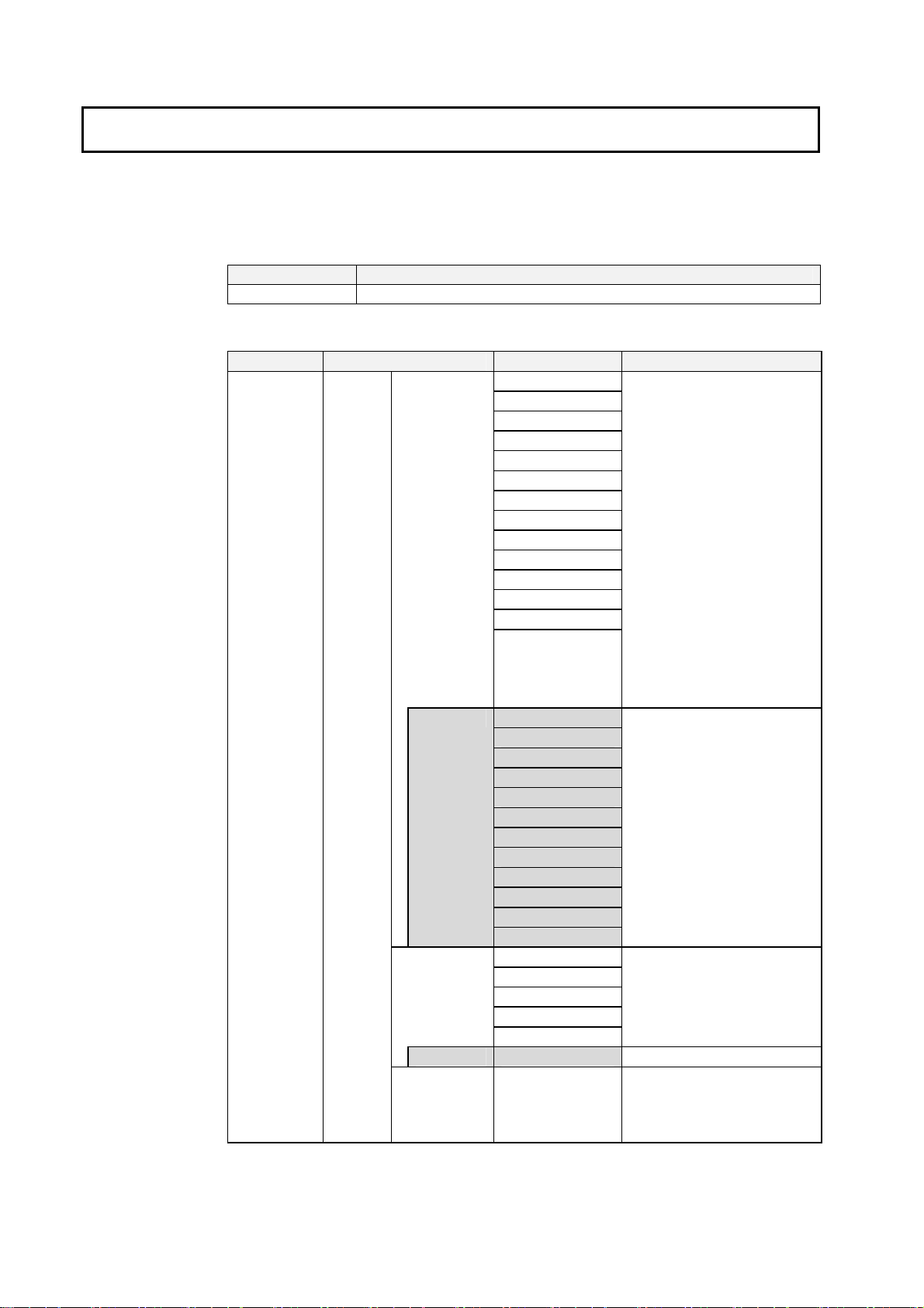
The Ladder Monitor is provided with the CX-Designer CD-ROM in the locations given
below. For version-2 NS-series PTs and NSJ Controllers with system version 6.6 or
higher, the Ladder Monitor is built into the system program for version-2 NS-series PTs
and NSJ Controllers with system version 6.6 or higher (except for the NS5-V2 and NSJ5).
CD-ROM Location on CD-ROM
CX-Designer
• CD-ROM: The following software is provided.
Software Folder name in CD-ROM File name Usage
Ladder
Monitor
Application
\Utility\English\LadderMonitorFunc
\ldrsetup
\ldrmt
\ldrmt_v1
\procon
\procon_v1 Procon
\ldrdata
Plcmon
Winmgr
Spydidmn
Aptextexecldrmt.sh
Aptextchkldrmt.sh
Checklist
Plcmon.ini
ldrmttbl.ini
Fun.bin
Procs
watchtask
dir
attr
grep
Aptvmod
Attr
Checklist
Dir
FONTS
Grep
Plcmon
Procs
Winmgr
Plcmon_E
Plcmon_J
Spydidmn
Procon
Pbtc_4832_0101
Pbts_4832_0101
Plcd_1616_0102
Plcd_1616_0202
This folder is empty
by default.
Copy the files directly to the
Memory Card.
For version-1 and version-2
NS-series PTs and NSJ
Controllers, all the files listed in
this table are required.
For version-2 NS-series PTs
and NSJ Controllers with NS
system version 6.6 or higher,
the Ladder Monitor is built into
the system program (except for
the NS5-V2 and NSJ5) and
thus a Memory Card is not
required.
For pre-version-1 NS-series
PTs, the files in the shaded
folders are not required on the
Memory Card.
Location for I/O comment file
extracted using the I/O
Comment Extracting Tool and
copied to the Memory Card
22

1-2 Checking the Package
Software Folder name in CD-ROM File name Usage
I/O Comment
Extracting
Tool
Operation
Manual
In PDF format
\iocmttool Setup.exe Install the I/O Comment
Extracting Tool on the
computer.
-
Ladder Monitor
I/O Comment
Extracting Tool
Read PDF files using Adobe
Acrobat.
23

1-3 Memory Cards
1-3 Memory Cards
A Memory Card is required to operate the Ladder Monitor. Prepare the Memory Card
before operating the Ladder Monitor.
Recommended Memory Cards
•
Model Capacity Memory type
HMC-EF183 128 MB Flash Memory
HMC-EF283 256 MB Flash Memory
HMC-EF583 512 MB Flash Memory
Note: The above Memory Cards cannot be used for the NS7-SV00/01(B) with lot number 0852 or
earlier.
24
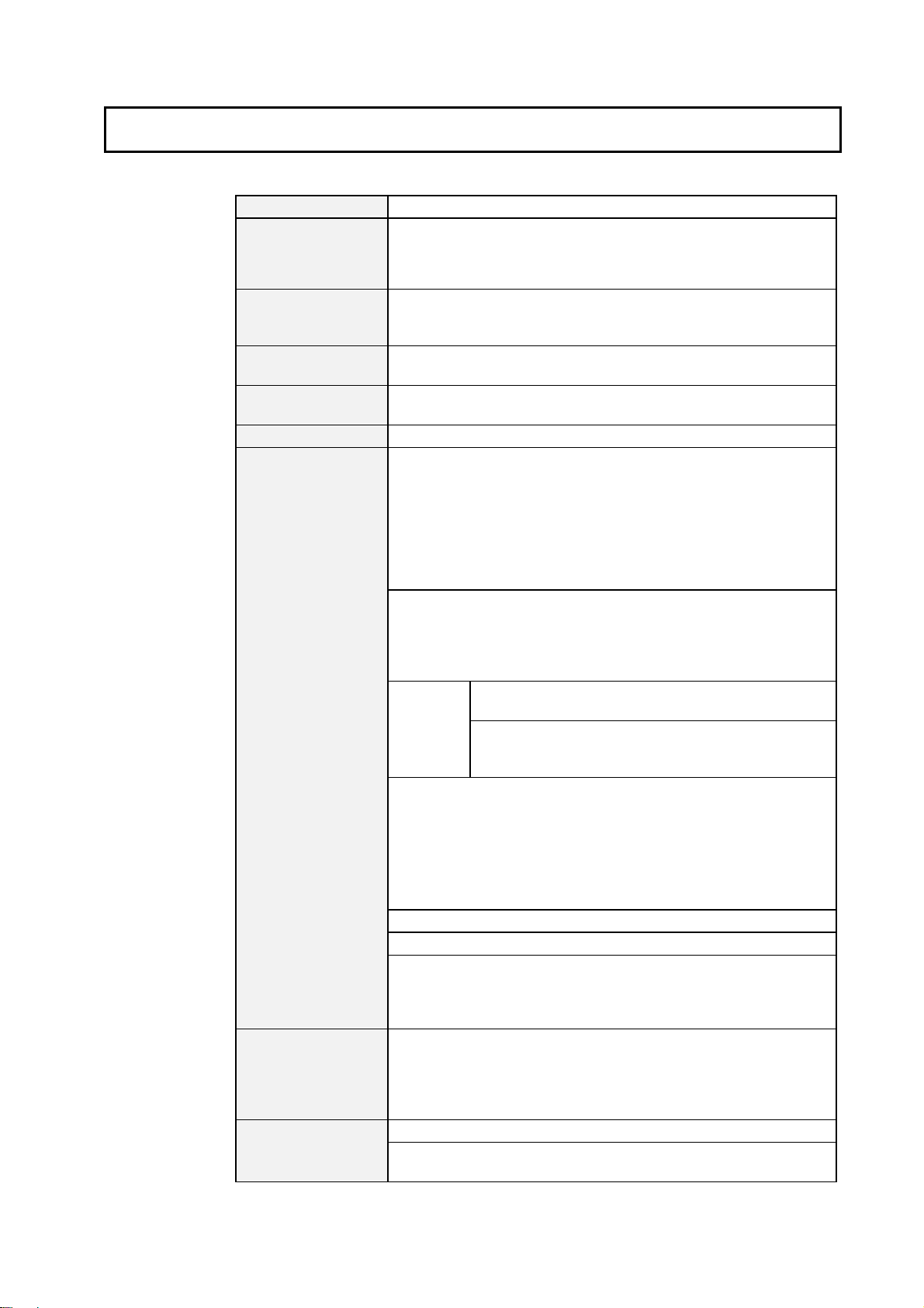
1-4 Specifications
The specifications of the Ladder Monitor are given below.
Applicable PLC (host)
Applicable NS-series
PT ports
Communications
modes between PLC
and PT
Port selection
method
Destination PLC
selection method
Startup method
Displaying ladder
program section
I/O comments
Ladder Monitor
SYSMAC CS/CJ Series, NSJ Series
Serial port A or B (RS-232C ports)
•
Ethernet port (for PTs with an Ethernet port)
•
Controller Link (Using an NS-CLK21 Controller Link Interface Unit)
•
NSJ Controller Section ports
•
Serial port A or B: 1:N NT Link
•
Ethernet port/Controller Link port: Settings to enable
•
communications are made in both the PLC and PT.
Setting screen of the Ladder Monitor (Only ports registered in CX-Designer
can be selected.)
Setting screen of the Ladder Monitor (Only hosts registered in CX-Designer
can be selected.)
From the System Menu of the PT or from user screens
Number of rows
NS15: 22 max.
•
NS12: 17 max.
•
NS10/8: 13 max.
•
The number depends on whether comment displays and Multiple I/O
Monitor are used.
Note: You can scroll one row at time when there are more than the above
number of rows in one program section.
Number of columns
NS15: 21 max.
•
NS12: 16 max.
•
NS10/8: 13 max.
•
Note: Columns cannot be scrolled.
Limitations
per
program
section
I/O comments
In the ladder display area, I/O comments can displayed in one line, three
•
lines, or not at all.
Up to five characters per line can be displayed for an I/O comment for a
•
particular address.
Specified addresses can be displayed in the I/O comment area (up to 71
•
characters for the NS15, 43 characters for the NS12, or 23 characters for
the NS10/8).
Section breaks: Displayed as “- [SECTION].”
Rung comments, comment boxes, and rung annotation are not displayed.
Block program: [BPRG] is displayed. (Mnemonics are not displayed in
block programs.)
Function blocks: -[FB] is displayed. (Function block contents are not
displayed.)
I/O comments can be read from a symbol table in the PLC and displayed.
This I/O comment data is saved in the PT, so it does not need to be read
from the tables the next time.
Note: If the symbol tables cannot be transferred to the PLC, the I/O
Comment Extracting Tool can be used to create an I/O comment file.
Ladder diagram status and word present values can be monitored.
Word present values can be displayed in hexadecimal, decimal, or signed
decimal.
1-4 Specifications
No. of TR bits: 8 max. (A program section using TR8 to TR15
cannot be displayed; a program section error will occur.
No. of lines: 22 max. (A program section with more than 22
lines cannot be displayed and the error message “This
program section cannot be shown” will be displayed.)
25
1-4 Specifications
Searching
Multiple I/O Monitor
Changing present
values and set values
Changing mode
Error display
Programming
Console function
Monitor screen hard
copies
The number of Ladder Monitor rows depends on the number of I/O comment lines
displayed and whether or not Multiple I/O Monitor is used, as shown in the following
tables.
Program addresses (step numbers), addresses, instructions, instructions
and addresses, searching from input bit to output instruction or searching
from sequence output instruction to input bit (JUMP Search)
Searches for specified alarms/events from a PT user screen (Alarm/Event
Summary and History).
Up to 30 search results can be remembered, and previously searched
program sections can be read again.
Number of monitored points:.
NS15: 20 max.
•
NS12: 16 max.
•
NS10/8: 12 max.
•
Changing the present values of words, force-setting/resetting bits, and
setting/resetting bits can be performed for the monitored points.
Specified bits can be set/reset, force-set/reset, or force-cancelled. Present
values of specified words can be changed. Present values can be input in
hexadecimal, decimal, or signed decimal.
Set values can be changed for specified timers and counters.
PLC operating mode can be changed.
PLC errors (non-fatal errors and fatal errors) can be displayed and cleared.
The Programming Console function of CS/CJ-series PLCs can be used on
the Ladder Monitor when the PLC is connected to serial port A or B. This
function is not supported for CJ2 CPU Units.
Monitor screens can be captured and saved to a Memory Card as bmp
files.
Multiple I/O Monitor Not Used
PT model No I/O comments
displayed
NS15
NS12
NS10/8
22 rows, 21 columns 14 rows, 21 columns 8 rows, 21 columns
17 rows, 16 columns 11 rows, 16 columns 6 rows, 16 columns
13 rows, 13 columns 8 rows, 13 columns 5 rows, 13 columns
Multiple I/O Monitor Used
PT model No I/O comments
displayed
NS15
NS12
NS10/8
19 rows, 21 columns 12 rows, 21 columns 7 rows, 21 columns
13 rows, 16 columns 9 rows, 16 columns 5 rows, 16 columns
10 rows, 13 columns 6 rows, 13 columns 4 rows, 13 columns
I/O comments: 1 line I/O comments: 3 lines
I/O comments: 1 line I/O comments: 3 lines
26
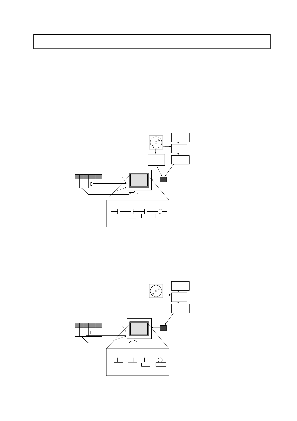
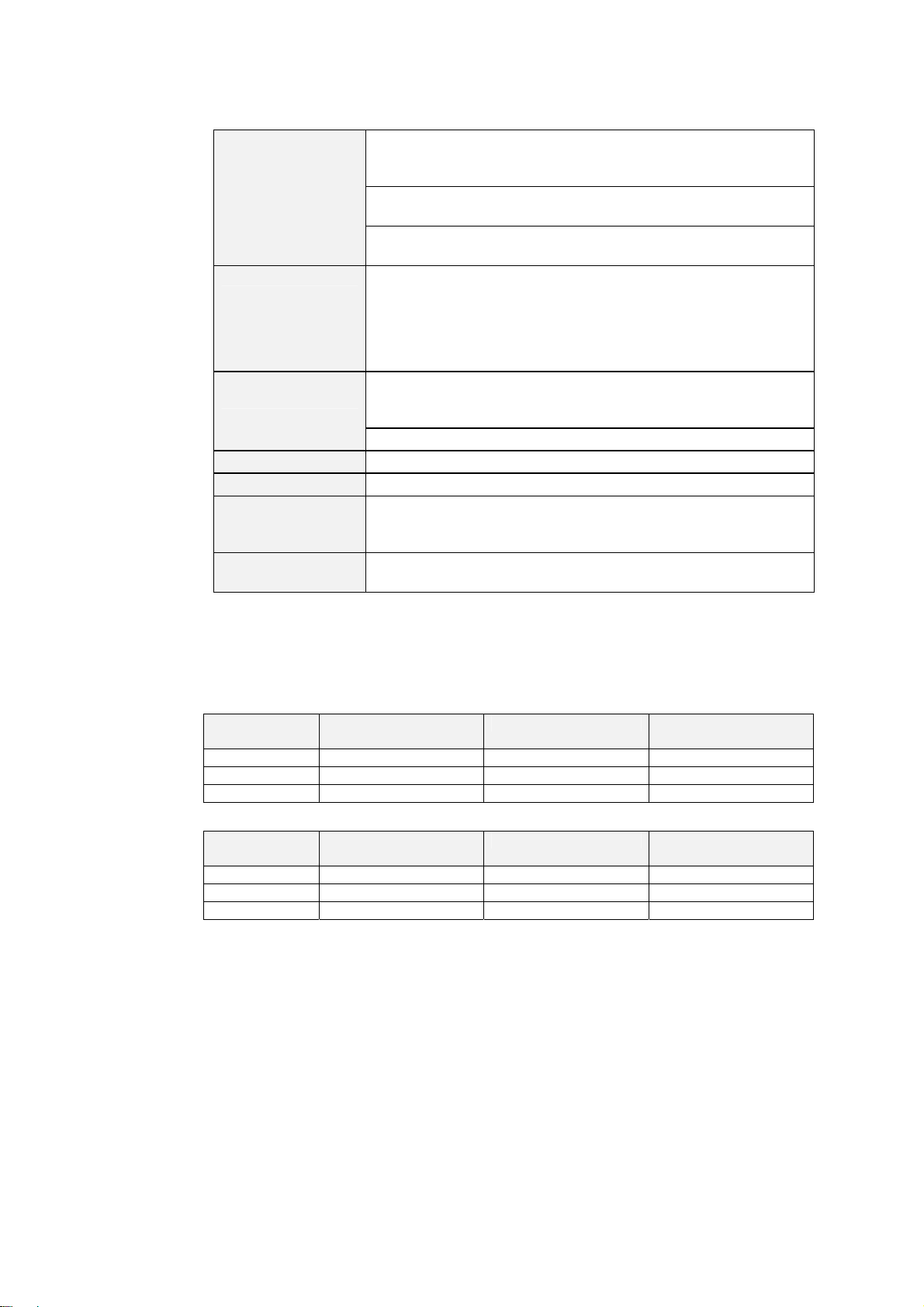
1-5 System Configuration
t
The Ladder Monitor can be started using the Special Screen Tab Page in the PT System
Menu when the system is configured with an NS-series PT connected to the host PLC by
RS-232C, Ethernet, or Controller Link communications. For pre-version-1 and version-1
NS-series PTs, however, a Memory Card containing the Ladder Monitor application must
be mounted at the back of the PT, as shown in the following diagram.
I/O comments can be read from a symbol table in the PLC. There is no need to copy I/O
comment files to a Memory Card when a symbol table is downloaded to a connected
PLC.
Pre-version-1 and Version-1 NS-series PTs
folder.
Controller Link
Interface Unit
CD-ROM
Ladder Monitor
Application
Copy the
ldrdrmt
CS/CJ-series
PLC (host)
Controller Link
1:N NT Link
RS-232C
Ethernet
Ethernet Port
Serial Port A or B
NS-series PT
Ladder Monitor (Started form the System Menu)
Install
Memory Card
Screen capture
data
CX-Programmer
CXT File
I/O Comment
Extracting Tool
I/O Comment File
for Ladder Monitor
Copy the file to the
folder.
ldrdata
1-5 System Configuration
Version-2 NS-series PTs
For version-2 NS-series PTs (except for the NS5-V2) with system version 6.6 or higher,
the Ladder Monitor is built into the system program and thus a Memory Card is not
required except for the following operations:
Creating hard copies of screens (i.e., screen captures).
Displaying I/O comment files that were created using the I/O Comment Extracting Tool.
CS/CJ-series
PLC (host)
Controller Link
1:N NT Link
RS-232C
Ethernet
Ethernet Por
Serial Port A or B
0000.00
0000.01
SW1
Ladder Monitor (Started form the System Menu)
SW2
NS-series PT
Controller Link
Interface Unit
ER 0002.00
ER
CD-ROM
LAMP01
Install
Screen capture
data
CX-Programmer
CXT File
I/O Comment
Extracting Tool
I/O Comment File
for Ladder Monitor
Copy the file to the
ldrdata folder.
Memory Card
0000.00
0000.01
SW1
SW2
ER 0002.00
LAMP01
ER
27

1-5 System Configuration
NSJ Controllers
For NSJ Controllers (except for the NSJ5) with NS system version 6.6 or higher, the
Ladder Monitor is built into the system program and thus a Memory Card is not required
except for the following operations.
Creating hard copies of screens (i.e., screen captures).
Displaying I/O comment files that were created using the I/O Comment Extracting Tool.
CS/CJ-series
PLC (host)
Ethernet Port
Serial Port A or B
1:N NT Link
RS-232C
Ethernet
NSJ-series PT
CD-ROM
Screen capture data
Install
Memory Card
CX-Programmer
CXT File
I/O Comment
Extracting Tool
I/O Comment File
for Ladder Monitor
Copy the file to the
ldrdata folder.
Ladder Monitor (Started form the System Menu.)
0000.00
SW1
0000.01
SW2
ER 0002.00
SW3
LAMP01
Manuals
Name Cat. No.
Programmable Terminal NS Series (-V1/-V2)
Setup Manual/Programming Manual
V083-E1-01
V073-E1-01
SYSMAC One NSJ Series NSJ Controller Operation Manual W452-E1-01
SYSMAC CX-Programmer User Manual Ver. 7.2
CX-Server User Manual
W446
SYSMAC CS/CJ Series Programming Console Operation Manual W341
Caution
Turn OFF the +5 V power supply before connecting or
disconnecting the RS-232C cable.
The +5 V circuit in the RS-232C equipment may be destroyed by
the inrush current from the conversion unit.
Note
After connecting a communications cable, always secure it with the screws.
Otherwise, the cable may disconnect, causing operation to fail.
Note
A Memory Card containing the Ladder Monitor application is required for version-2
NS-series PTs and NSJ Controllers with system version 6.5 or lower.
Note
The entire system may stop depending on how the power is turned ON/OFF. Follow
the correct procedure when turning the power ON/OFF. Otherwise, the system may
operate unpredictably.
28
 Loading...