

Page 1

OPERATION MANUAL
NS-Designer
NS-Series
NS-NSDC1-V6
Cat. No. V074-E1-07
Page 2

Notice:
OMRON products are manufactured for use according to proper procedures by a qualified operator and
only for the purposes described in this manual.
The following conventions are used to indicate and classify precautions in this manual. Always heed the
information provided with them. Failure to heed precautions can result in injury to people or damage to
property.
DANGER Indicates an imminently hazardous situation which, if not avoided, will result in death or
serious injury. Additionally, there may be severe property damage.
WARNING Indicates a potentially hazardous situation which, if not avoided, could result in death or
serious injury. Additionally, there may be severe property damage.
Caution Indicates a potentially hazardous situation which, if not avoided, may result in minor or
moderate injury, or property damage.
OMRON Product References
All OMRON products are capitalized in this manual. The word "Unit" is also capitalized when it refers to
an OMRON product, regardless of whether or not it appears in the proper name of the product.
The abbreviation "Ch," which appears in some displays and on some OMRON products, often means
"word" and is abbreviated "Wd" in documentation in this sense.
Visual Aids
The following headings appear in the left column of the manual to help you locate different types of
information.
1, 2, 3... 1. Indicates lists of one sort or another, such as procedures, checklists, etc.
OMRON, 2002
All rights reserved. No part of this publication may be reproduced, stored in a retrieval system, or transmitted, in any form, or
by any means, mechanical, electronic, photocopying, recording, or otherwise, without the prior written permission of
OMRON.
No patent liability is assumed with respect to the use of the information contained herein. Moreover, because OMRON is
constantly striving to improve its high-quality products, the information contained in this manual is subject to change without
notice. Every precaution has been taken in the preparation of this manual. Nevertheless, OMRON assumes no responsibility
for errors or omissions. Neither is any liability assumed for damages resulting from the use of the information contained in this
publication.
Note Indicates information of particular interest for efficient and convenient operation
of the product.
P-1
Page 3

Preliminary Material Introduction
NS-Designer Operation Manual
Introduction
Thank you for purchasing the NS-Designer.
The NS-Designer is a software package that enables creating and maintaining screen data for
OMRON NS-series Programmable Terminals.
To take full advantage of the NS-series Programmable Terminals, please be sure that you understand
the functions and performance of the NS-Designer before attempting to use it. When using an
NS-series PT, please also refer to the NS Series Setup Manual and the NS Series Programming
Manual.
Intended Audience
This manual is intended for the following personnel, who must also have knowledge of electrical systems (an electrical engineer or the equivalent).
Personnel in charge of introducing FA systems into production facilities. •
•
Personnel in charge of designing FA systems.
•
Personnel in charge of installing and connecting FA systems.
•
Personnel in charge of managing FA systems and facilities.
Precaution
•
The user must operate the product according to the performance specifications described in the operation manuals.
•
Do not use the PT touch switch input functions for applications where danger to human life or serious
property damage is possible, or for emergency switch applications.
•
Before using the product under conditions which are not described in the manual or applying the
product to nuclear control systems, railroad systems, aviation systems, vehicles, combustion systems, medical equipment, amusement machines, safety equipment, and other systems, machines
and equipment that may have a serious influence on lives and property if used improperly, consult
your OMRON representative.
•
Make sure that the ratings and performance characteristics of the product are sufficient for the systems, machines, and equipment, and be sure to provide the systems, machines, and equipment with
double safety mechanisms.
•
This manual provides information for using the NS-Designer. Be sure to read this manual before attempting to use the NS-Designer and keep this manual close at hand for reference during installation
and operation.
P-2
Page 4

Preliminary Material Notation and Terminology
NS-Designer Operation Manual
Notation and Terminology
The following notation and terminology are used in this manual.
Notation
The following notation is used in this manual.
Note
Indicates additional information on operation, descriptions, or settings.
NNoottee
Note
♦
Terminology
PT In this manual, indicates an NS-series Programmable Terminal.
PLC Indicates OMRON Programmable Controllers.
Host Indicates the PLC, FA computer, or personal computer functioning as the control
device and interfaced with the NS-series PT.
P-3
Page 5

Preliminary Material Related Manuals
NS-Designer Operation Manual
Related Manuals
This manual
The following manuals are used for NS-series PTs. (The boxes at the end of the catalog numbers indicate the revision code.)
NS-Designer Operating Procedures:
• NS-Designer Operation Manual.......................................................................V074-E1-@
Describes operating procedures for the NS-Designer, which is used to create the screens displayed on
the PT and transfer them to the PT. It includes screen creation and transfer procedures. Refer to this
manual for information on operating methods and detailed operating procedures.
This manual deals with details of NS-Designer operation. Refer to the following manuals for information
on NS-series PT operation.
Detailed Setting Methods for Functional Objects and Other Objects:
• NS Series Programming Manual......................................................................V073-E1-@
Describes the screen configurations, object functions, and host communications for the PT.
Basic NS-series PT Functions, Operations, and Limitations:
• NS series -V1/-V2 Setup Manual ......................................................................V083-E1-@
Provides information on NS Series -V1 models (i.e., NS12-V1, NS10-V1, NS8-V1, and NS5-V1), and
NS Series -V2 models (i.e., NS5-V2).
Describes how to connect the PT to the host and peripheral devices, methods to setup communications and operation, and procedures for maintenance.
Refer to the NS Series Programming Manual (V073-E1-@) for information on PT functions and specific
operating procedures.
First-time Users of NS-series Programmable Terminals:
• Tutorial (Installed from NS-Designer CD-ROM.)
This tutorial is designed for first-time users of NS-series PTs. It provides examples of operations from
creating a simple screen through starting actual operation. When the NS-Designer is installed, the tutorial is installed on the hard disk as PDF files.
NS-series Macro Function:
• Macro Reference (Installed from NS-Designer CD-ROM.)
The online help for the NS-Designer contains detailed information on the NS-series macro functions.
The Macro Reference contains essentially the same information, and it is installed on the hard disk as
PDF Files when the NS-Designer is installed. Use either the online help or the Macro Reference,
whichever is more convenient.
Confirming PLC Functions and Operation:
• PLC Operation Manuals
Refer to the operation manuals for individual PLC Units (e.g., the CPU Unit, Special I/O Units, CPU
Bus Units, Communications Units, etc) to obtain information on PLC functions and operation.
P-4
Page 6
Read and Understand This Manual
Please read and understand this manual before using the product. Please consult your OMRON representative if you have any questions or comments.
Warranty and Limitations of Liability
WARRANTY
OMRON's exclusive warranty is that the products are free from defects in materials and workmanship for a period
of one year (or other period if specified) from date of sale by OMRON.
OMRON MAKES NO WARRANTY OR REPRESENTATION, EXPRESS OR IMPLIED, REGARDING
NON-INFRINGEMENT, MERCHANTABILITY, OR FITNESS FOR PARTICULAR PURPOSE OF THE
PRODUCTS. ANY BUYER OR USER ACKNOWLEDGES THAT THE BUYER OR USER ALONE HAS
DETERMINED THAT THE PRODUCTS WILL SUITABLY MEET THE REQUIREMENTS OF THEIR INTENDED
USE. OMRON DISCLAIMS ALL OTHER WARRANTIES, EXPRESS OR IMPLIED.
LIMITATIONS OF LIABILITY
OMRON SHALL NOT BE RESPONSIBLE FOR SPECIAL, INDIRECT, OR CONSEQUENTIAL DAMAGES, LOSS
OF PROFITS OR COMMERCIAL LOSS IN ANY WAY CONNECTED WITH THE PRODUCTS, WHETHER SUCH
CLAIM IS BASED ON CONTRACT, WARRANTY, NEGLIGENCE, OR STRICT LIABILITY.
In no event shall the responsibility of OMRON for any act exceed the individual price of the product on which
liability is asserted.
IN NO EVENT SHALL OMRON BE RESPONSIBLE FOR WARRANTY, REPAIR, OR OTHER CLAIMS
REGARDING THE PRODUCTS UNLESS OMRON'S ANALYSIS CONFIRMS THAT THE PRODUCTS WERE
PROPERLY HANDLED, STORED, INSTALLED, AND MAINTAINED AND NOT SUBJECT TO
CONTAMINATION, ABUSE, MISUSE, OR INAPPROPRIATE MODIFICATION OR REPAIR.
P-5
Page 7

Application Considerations
SUITABILITY FOR USE
OMRON shall not be responsible for conformity with any standards, codes, or regulations that apply to the combination of products in the customer's application or use of the products.
At the customer's request, OMRON will provide applicable third party certification documents identifying ratings
and limitations of use that apply to the products. This information by itself is not sufficient for a complete determination of the suitability of the products in combination with the end product, machine, system, or other application or use.
The following are some examples of applications for which particular attention must be given. This is not intended
to be an exhaustive list of all possible uses of the products, nor is it intended to imply that the uses listed may be
suitable for the products:
•
Outdoor use, uses involving potential chemical contamination or electrical interference, or conditions or uses not
described in this manual.
•
Nuclear energy control systems, combustion systems, railroad systems, aviation systems, medical equipment,
amusement machines, vehicles, safety equipment, and installations subject to separate industry or government
regulations.
•
Systems, machines, and equipment that could present a risk to life or property.
Please know and observe all prohibitions of use applicable to the products.
NEVER USE THE PRODUCTS FOR AN APPLICATION INVOLVING SERIOUS RISK TO LIFE OR PROPERTY
WITHOUT ENSURING THAT THE SYSTEM AS A WHOLE HAS BEEN DESIGNED TO ADDRESS THE RISKS,
AND THAT THE OMRON PRODUCTS ARE PROPERLY RATED AND INSTALLED FOR THE INTENDED USE
WITHIN THE OVERALL EQUIPMENT OR SYSTEM.
PROGRAMMABLE PRODUCTS
OMRON shall not be responsible for the user's programming of a programmable product, or any consequence
thereof.
P-6
Page 8
Disclaimers
CHANGE IN SPECIFICATIONS
Product specifications and accessories may be changed at any time based on improvements and other reasons.
It is our practice to change model numbers when published ratings or features are changed, or when significant
construction changes are made. However, some specifications of the products may be changed without any notice. When in doubt, special model numbers may be assigned to fix or establish key specifications for your application on your request. Please consult with your OMRON representative at any time to confirm actual specifications of purchased products.
DIMENSIONS AND WEIGHTS
Dimensions and weights are nominal and are not to be used for manufacturing purposes, even when tolerances
are shown.
PERFORMANCE DATA
Performance data given in this manual is provided as a guide for the user in determining suitability and does not
constitute a warranty. It may represent the result of OMRON's test conditions, and the users must correlate it to
actual application requirements. Actual performance is subject to the OMRON Warranty and Limitations of Liability.
ERRORS AND OMISSIONS
The information in this manual has been carefully checked and is believed to be accurate; however, no responsibility is assumed for clerical, typographical, or proofreading errors, or omissions.
P-7
Page 9

Contents
NS-Designer Operation Manual
Contents
Notice .......................................................................................................................................................... 1
Introduction .......................................................................................................................................................... 2
Notation and Terminology ...................................................................................................................................... 3
Related Manuals ...................................................................................................................................................... 4
Read and Understand This Manual ......................................................................................................................... 5
Application Considerations ..................................................................................................................................... 6
Disclaimers .......................................................................................................................................................... 7
Section 1 Overview
1-1 The NS-Designer........................................................................................................................................ 1-1
1-2 System Requirements .................................................................................................................................1-3
1-2-1 Hardware.......................................................................................................................................... 1-3
1-2-2 Equipment Required to Transfer Screen Data..................................................................................1-3
1-3 Basic Configuration and Functions............................................................................................................1-4
1-3-1 Project Overview..............................................................................................................................1-4
1-3-2 Manipulating Data on the PLC ........................................................................................................1-5
1-3-3 PT Memory ...................................................................................................................................... 1-6
1-3-4 Host Registration and Address......................................................................................................... 1-7
1-3-5 Screen Types and Applications........................................................................................................1-7
1-3-6 Object Types .................................................................................................................................... 1-8
1-3-7 Functions Used to Create Screens.................................................................................................. 1-10
1-3-8 Data Log.........................................................................................................................................1-13
1-3-9 Alarms/Events................................................................................................................................ 1-13
1-3-10 Data Blocks....................................................................................................................................1-14
1-3-11 Video Display ................................................................................................................................1-15
1-3-12 Importing and Exporting CSV Files...............................................................................................1-16
1-3-13 Validating.......................................................................................................................................1-16
1-4 Outline of Operational Flow ....................................................................................................................1-17
1-5 Menu Commands .....................................................................................................................................1-18
1-6 Functions Added in Version 3.0...............................................................................................................1-21
1-7 Functions Added in Version 4.0...............................................................................................................1-22
1-8 Functions Added in Version 5.0...............................................................................................................1-22
1-9 Functions Added in Version 6.0...............................................................................................................1-22
1-10 Functions Added in Version 6.2............................................................................................................... 1-23
Section 2 Setup, Starting, and Exiting
2-1 Before Installing the NS-Designer ............................................................................................................. 2-1
2-2 Installing the NS-Designer.........................................................................................................................2-2
2-2-1 Basic Installation Operations ...........................................................................................................2-2
2-2-2 Installation Procedure ......................................................................................................................2-3
2-2-3 Uninstalling...................................................................................................................................... 2-7
2-2-4 Installing USB Drivers for NS-Series PTs.......................................................................................2-9
2-3 Starting the NS-Designer .........................................................................................................................2-14
2-4 Exiting the NS-Designer ..........................................................................................................................2-15
2-5 User Interface ........................................................................................................................................... 2-16
2-5-1 Basic Screen Functions .................................................................................................................. 2-16
2-5-2 Dialog Box Main Functions...........................................................................................................2-21
i
Page 10

Contents
NS-Designer Operation Manual
Section 3 Manipulating Project Files
3-1 Projects.......................................................................................................................................................3-1
3-2 Creating New Projects................................................................................................................................3-2
3-3 Opening Existing Projects..........................................................................................................................3-3
3-4 Saving Projects ...........................................................................................................................................3-5
3-5 Saving a Project Under a Different Name..................................................................................................3-7
3-6 Opening Recent Projects ............................................................................................................................3-8
3-7 Opening Template Projects ........................................................................................................................ 3-9
3-7-1 Specifying Template Projects (Flowchart Step 1)..........................................................................3-10
3-7-2 Reusing Screens (Flowchart Steps 2 to 4)......................................................................................3-10
3-7-3 Canceling Template Projects..........................................................................................................3-11
3-8 Project Maintenance .................................................................................................................................3-12
3-8-1 Procedures...................................................................................................................................... 3-12
3-9 Project Properties .....................................................................................................................................3-17
3-9-1 Procedure ....................................................................................................................................... 3-17
3-10 Changing the PT Model ...........................................................................................................................3-21
Section 4 Screen Types and Operations
4-1 Basic Operations ........................................................................................................................................4-1
4-1-1 Setting Screen Properties .................................................................................................................4-1
4-1-2 Grid Setting......................................................................................................................................4-4
4-1-3 Switching Items Displayed for Objects............................................................................................4-5
4-1-4 Changing the Display..................................................................................................................... 4-14
4-1-5 Switch Label ..................................................................................................................................4-15
4-1-6 Show Touch Points ........................................................................................................................4-16
4-1-7 Zoom..............................................................................................................................................4-16
4-1-8 Refreshing......................................................................................................................................4-17
4-2 Creating and Saving Screens.................................................................................................................... 4-18
4-2-1 Creating New Screens....................................................................................................................4-18
4-1-2 Screen Maintenance ....................................................................................................................... 4-22
4-1-3 Procedure ....................................................................................................................................... 4-23
4-3 Sheets .....................................................................................................................................................4-24
4-3-1 Creating New Sheets......................................................................................................................4-24
4-3-2 Opening Existing Sheets ................................................................................................................ 4-25
4-3-3 Closing Sheets................................................................................................................................ 4-25
4-3-4 Saving Sheets ................................................................................................................................. 4-26
4-3-5 Applying Sheets ............................................................................................................................. 4-26
4-3-6 Sheet Maintenance ......................................................................................................................... 4-27
4-4 Frames .....................................................................................................................................................4-28
4-4-1 Creating Frame Tab Names ...........................................................................................................4-30
4-4-2 Switching Frame Pages..................................................................................................................4-31
Section 5 Object Operations
5-1 Creating Functional Objects....................................................................................................................... 5-1
5-1-1 Creating One Object at a Time.........................................................................................................5-1
5-1-2 Property Settings..............................................................................................................................5-2
5-1-3 Creating Functional Objects Using Tables.......................................................................................5-3
ii
Page 11

Contents
NS-Designer Operation Manual
5-2 Creating Fixed Objects............................................................................................................................... 5-8
5-2-1 Drawing New Fixed Objects............................................................................................................5-8
5-3 Pop-up Menus ..........................................................................................................................................5-12
5-4 Editing .....................................................................................................................................................5-13
5-4-1 Undo...............................................................................................................................................5-13
5-4-2 Redo ...............................................................................................................................................5-13
5-4-3 Cut..................................................................................................................................................5-14
5-4-4 Copy............................................................................................................................................... 5-15
5-4-5 Paste...............................................................................................................................................5-16
5-4-6 Delete ............................................................................................................................................. 5-17
5-4-7 Find ................................................................................................................................................ 5-17
5-4-8 Replace...........................................................................................................................................5-20
5-4-9 Select All........................................................................................................................................ 5-22
5-4-10 Repeat ............................................................................................................................................5-24
5-5 Layout Functions...................................................................................................................................... 5-25
5-5-1 Changing Size ................................................................................................................................ 5-25
5-5-2 Moving Objects..............................................................................................................................5-25
5-5-3 Aligning and Distributing Objects .................................................................................................5-26
5-5-4 Make Same Size............................................................................................................................. 5-27
5-5-5 Ordering Objects............................................................................................................................5-29
5-5-6 Nudging Objects ............................................................................................................................5-29
5-5-7 Rotating and Flipping Objects .......................................................................................................5-30
5-5-8 Modifying Objects .........................................................................................................................5-31
5-5-9 Grouping and Ungrouping Objects ................................................................................................5-33
5-6 Colors ..................................................................................................................................................... 5-35
5-7 Address Settings....................................................................................................................................... 5-36
5-7-1 Setting Addresses...........................................................................................................................5-37
5-7-2 Registering Hosts ........................................................................................................................... 5-38
5-8 Displaying and Searching Functional Object Lists .................................................................................. 5-42
5-8-1 Redisplaying Lists.......................................................................................................................... 5-45
5-9 Listing Functional Objects Used .............................................................................................................. 5-46
5-9-1 Displaying Lists of Used Functional Objects.................................................................................5-46
5-9-2 Jumping to Screens, Tables, and Frames .......................................................................................5-48
5-10 Batch Settings........................................................................................................................................... 5-49
5-11 Listing Addresses Used ............................................................................................................................ 5-55
5-12 Cross-referencing Addresses.................................................................................................................... 5-59
5-13 Library Registration and Sharing Objects ................................................................................................ 5-63
5-13-1 Registering Library Objects ........................................................................................................... 5-63
5-14 Object Defaults......................................................................................................................................... 5-68
5-14-1 Registering Defaults....................................................................................................................... 5-68
5-14-2 Resetting Defined Defaults ............................................................................................................ 5-68
5-15 Editing Background Bitmaps ...................................................................................................................5-70
5-16 Options.....................................................................................................................................................5-71
5-16-1 Color Dialog...................................................................................................................................5-71
5-16-2 Edit/Disp. ....................................................................................................................................... 5-71
5-16-3 Editor..............................................................................................................................................5-72
5-16-4 Labels............................................................................................................................................. 5-72
iii
Page 12

Contents
NS-Designer Operation Manual
Section 6 Programming Macros
6-1 Registering Macros ....................................................................................................................................6-1
6-1-1 Registering Macros to Projects ........................................................................................................6-2
6-1-2 Registering Macros to Functional Objects.......................................................................................6-5
6-2 List of Error Messages ............................................................................................................................... 6-8
Section 7 System Settings
7-1 Settings....................................................................................................................................................... 7-1
7-1-1 Common Procedure..........................................................................................................................7-1
7-1-2 PT Operations ..................................................................................................................................7-1
7-1-3 Initial................................................................................................................................................7-2
7-1-4 History..............................................................................................................................................7-4
7-1-5 Comm-All ........................................................................................................................................ 7-5
7-1-6 Detailed..........................................................................................................................................7-10
7-1-7 Printer.............................................................................................................................................7-16
7-1-8 Video.............................................................................................................................................. 7-17
Section 8 Testing
8-1 Test Function.............................................................................................................................................. 8-1
8-2 Test Tool ....................................................................................................................................................8-6
8-2-1 Display Formats ............................................................................................................................... 8-6
8-2-2 Setting Values .................................................................................................................................. 8-7
Section 9 Validation
9-1 Validation Settings ..................................................................................................................................... 9-1
9-2 Validation Results ......................................................................................................................................9-2
9-2-1 No Error Detected ............................................................................................................................ 9-2
9-2-2 Error Detected..................................................................................................................................9-2
9-3 List of Validation Items..............................................................................................................................9-4
Section 10 Transferring Data
10-1 Transferring Data to the PT...................................................................................................................... 10-1
10-1-1 Preparations and Procedures before Connecting............................................................................10-2
10-1-2 Communications Settings for NS-Designer ................................................................................. 10-14
10-1-3 Transferring Project Data.............................................................................................................10-20
10-1-4 Transferring Screen Data .............................................................................................................10-23
10-1-5 Transferring the System Program ................................................................................................10-25
10-2 Transferring Data to and from a Memory Card......................................................................................10-29
10-2-1 Preparations for Transferring to a Memory Card in PT ...............................................................10-29
10-2-2 Procedure for Transferring Data to a Memory Card in the PT..................................................... 10-31
10-3 Data Transfer Using SPMA ...................................................................................................................10-33
10-3-1 Overview of SPMA...................................................................................................................... 10-33
10-3-2 SPMA Features ............................................................................................................................ 10-33
10-3-3 System Configuration ..................................................................................................................10-34
10-3-4 Procedural Example .....................................................................................................................10-36
iv
Page 13

Contents
NS-Designer Operation Manual
Section 11 Printing
11-1 Printing Project Information..................................................................................................................... 11-1
11-1-1 Printing Samples ............................................................................................................................11-2
11-2 Printing Page Information ........................................................................................................................11-4
11-2-1 Printing Samples ............................................................................................................................11-6
11-3 Previews...................................................................................................................................................11-8
11-4 Outputting to an RTF File ........................................................................................................................11-9
11-5 Headers and Footers ............................................................................................................................... 11-10
11-6 Margins ..................................................................................................................................................11-12
Section 12 Importing/Exporting CSV Files
12-1 Exporting CSV Files ................................................................................................................................12-1
12-2 Editing CSV Files ....................................................................................................................................12-2
12-3 Importing CSV Files ................................................................................................................................12-3
Section 13 Multi-language Display
13-1 Overview..................................................................................................................................................13-1
13-2 Creating Multi-language Display Screens................................................................................................13-2
13-2-1 Inputting Multi-language Characters in NS-Designer Property Settings .......................................13-2
13-2-2 Displaying Multi-language Characters Using Indirect Object Specification .................................13-9
13-2-3 Creating Multi-language Display Screens Using the CSV Import/Export Function.................... 13-11
Appendices
Appendix 1 Quick Reference ........................................................................................................................... A-1
Appendix 2 Objects........................................................................................................................................ A-12
Appendix 3 Shortcut Keys.............................................................................................................................. A-16
Appendix 4 Version Information.................................................................................................................... A-17
Appendix 5 Resource Report.......................................................................................................................... A-18
Appendix 6 Error Messages ........................................................................................................................... A-19
Appendix 7 Connecting Cable Specifications ................................................................................................A-26
Appendix 8 Details of CLK Status................................................................................................................. A-28
Appendix 9 Converting Data between Different Versions of NS-series Products .........................................A-31
v
Page 14

Section 1 Overview
NS-Designer Operation Manual
Section 1 Overview
This section describes the specifications and functions of the NS-Designer to provide a basic understanding of the
capabilities of the NS-Designer for first-time users.
1-1 The NS-Designer ......................................................................................................................................... 1-1
1-2 System Requirements ..................................................................................................................................1-3
1-3 Basic Configuration and Functions.............................................................................................................. 1-4
1-4 Outline of Operational Flow ...................................................................................................................... 1-17
1-5 Menu Commands....................................................................................................................................... 1-18
1-6 Functions Added in Version 3.0 ................................................................................................................1-21
1-7 Functions Added in Version 4.0 ................................................................................................................1-22
1-8 Functions Added in Version 5.0 ................................................................................................................1-22
1-9 Functions Added in Version 6.0 ................................................................................................................1-22
1-10 Functions Added in Version 6.2 ................................................................................................................1-23
Page 15
Section 1 Overview 1-1 The NS-Designer
NS-Designer Operation Manual
1-1 The NS-Designer
The NS-Designer is an application software package that can be run on Windows 95, 98, NT, Me, 2000,
or XP to create screen data for NS-series Programmable Terminals (referred to as "PTs").
The NS-Designer enables using a graphic Windows interface and Windows operating environment so
that screens can be created simply and easily by practically anyone.
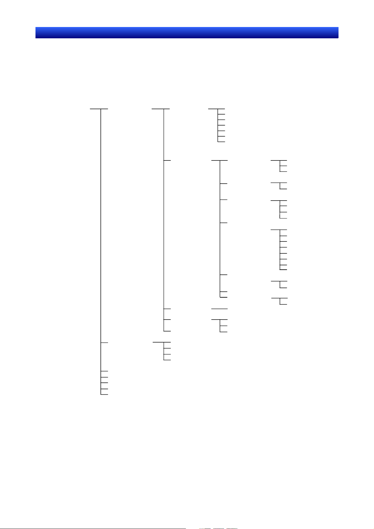
The data created on the NS-Designer consists of the following objects.
Data created on
NS-Designer
(project)
User screens
Sheets
Numeric units and scale settings
Alarm/event settings
Data log settings
Data block settings
Library
Fixed objects
Functional objects
Ta bl e s
Frames
Backgrounds
Fixed objects
Functional objects
Ta bl e s
Frames
Rectangles
Circles/ovals
Lines
Polylines
Polygons
Sectors
Arcs
Buttons
Lamps
Display and input
Display
System clock
Alarms/events
Data block tables
Functional objects
Fixed objects
Functional objects
Ta bl e s
ON/OFF buttons
Word buttons
Command buttons
Bit lamps
Word lamps
Numeral display & input
String display & input
Thumbwheel switches
Temporary input
Text
List selections
Level meters
Bitmaps
Analogue meters
Broken-line graphs
Data log graphs
Video display
Dates
Times
Alarm/event displays
Alarm/event summaries
and histories
1-1
Page 16
Section 1 Overview 1-1 The NS-Designer
i
NS-Designer Operation Manual
User Screen
Fixed graphic
Frame
Functional
object
Functional
object
Sheet
Functional
object
Ta bl e
Overlaid
W
ndows
Sheet objects
Product Components
The following software and data are included with the NS-NSDC1-V@.
NS-Designer Software •
•
Transfer Program
Tool for transferring systems, projects, screens, and settings files.
•
Memory Card Transfer Tool
Tool for exchanging data with the Memory Card mounted to the PT.
•
NT631C Conversion Support Tool
•
CX-Server
•
PT System Program (replacement program)
•
Operation Manuals
The operation manuals include an NS-series Macro Reference, an NS-Series Tutorial Manual, and a
Host Connection Manual.
•
Sample Data
Sample data of the screens created in the NS-series tutorial is included.
•
Switch Box Utility
Tool for helping to debug the operation of PLCs.
•
SAP (Smart Active Parts) Data
Libraries containing setting/monitor screens (e.g., for Position Control Units and Temperature Controllers).
1-2
Page 17

Section 1 Overview 1-2 System Requirements
NS-Designer Operation Manual
1-2 System Requirements
The following are required to use the NS-Designer.
1-2-1 Hardware
Recommended Processor
Intel Celeron 400 MHz or better required.
Computer
IBM PC/AT or compatible capable of running the required OS.
Recommended Memory
64 Mbytes or more required. (Be sure to provide sufficient capacity, observing the recommend values
for the OS.)
Available Disk Space
200 Mbytes or more recommended.
CD-ROM Drive
Required to install the NS-Designer.
Monitor
VGA monitor required for DOS computers. A resolution of 800 x 600 pixels or higher is recommended.
If the display resolution in the Windows screen properties is set to a lower setting, such as 640 x 480
pixels, portions of the NS-Designer windows may not be displayed. If this happens, increase the resolution. If large display fonts are used, not all of the text may fit in dialog boxes, preventing correct display. If this happens, use the small display fonts.
Mouse
A mouse supported by the OS must be used.
Operating System
Any of the following operating systems can be used: Microsoft Windows 95, Microsoft Windows 98,
Microsoft Windows Me, or Microsoft Windows NT (version 4.0, service pack 6a or higher), Microsoft
Windows 2000 (service pack 3 or higher), or Microsoft XP.
Microsoft Windows 3.1 is not supported.
Internet Explorer version 5.5 or higher is required.
1-2-2 Equipment Required to Transfer Screen Data
RS-232C connection cable
Ethernet cable
Memory Cards
Refer to Appendix 7 Connecting Cable Specifications for cable specifications.
1-3
Page 18
Section 1 Overview 1-3 Basic Configuration and Functions
NS-Designer Operation Manual
1-3 Basic Configuration and Functions
1-3-1 Project Overview
A project contains all of the objects and settings required for a group of user screens.
The project name is specified to access data when editing on the NS-Designer or transferring data to
PT.
System setting for
PT operation
Password setting
User screens
Unit and scale
setting
Data log setting
Library objects
Alarm/event
setting
A wide variety of objects can be used as required to create screens.
Some of the objects that can be used are described below.
Fixed Objects
Fixed objects, which do not provide any input functions, can be created on a screen.
Although fixed objects can be set to flicker, they are otherwise displayed on the screen in a constant
state.
Functional Objects
Functional objects can be used to communicate with internal memory in the PT or with a PLC. Functional objects have both graphic and operational properties. The display of functional objects can be
changed according to the status of the PT or PLC, and they can be used to input data through operations from the PT.
Table
A table object provides multiple functional objects in a single table format.
Frame
A frame object enables the creation of areas on a screen so that only part of the screen can be
switched to another page. Frames consist of more than one page, and the displayed contents of the
functional objects configuring each page can be switched based on PT or PLC status. Frames can
contain fixed objects, functional objects, and tables.
Background
A background is a graphic screen that is displayed as the background of other screens.
Bitmap files and JPEG files can be displayed as backgrounds.
Registering Created Objects
Created objects can be registered in a library so that they can be easily reused at many different locations or on different screens.
The following objects can be registered in the library.
Fixed objects, functional objects, tables, and frames
1-4
Page 19
Section 1 Overview 1-3 Basic Configuration and Functions
p
NS-Designer Operation Manual
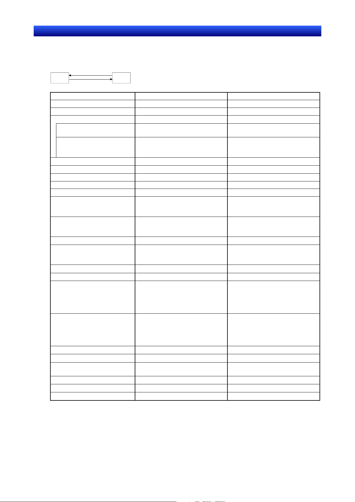
1-3-2 Manipulating Data on the PLC
Data can be input to and output from a PLC using the following objects, enabling values in memory to
be set or the screen data to be updated according to changes in memory.
Input
PT
ON/OFF Button OK OK
Word Button OK OK
Command Button
Switch Screen OK
Key Button OK
Bit Lamp OK
Word Lamp OK
Numeral Display & Input OK OK
String Display & Input OK OK
Thumbwheel Switch OK OK
Text OK
List Selection OK
Level Meter OK
Bitmap OK
Analogue Meter OK
Video Display
Broken-line Graph OK
Data Log Graph OK
Date/Time
Alarm/Event Display OK
Alarm/Event Summary & History
Data Block Table
Frames
Temporary input
Out
ut
Object Input Output
PLC
Indirect Specification of Screens
Indirect Specification of Character
Strings to Send
(Indirect Reference of Display
Strings)
(Address for specifying the File
Lines)
(Indirect Specification of Display
Data)
(Specifying Display Update Bits)
(Specifying Number of Display Re-
freshes)
(Broken-line Monitor Address)
(Monitor Address)
(Log Timing)
(Scale for Time Axis)
(Address for updating Display)
OK
OK
OK
OK
(Writing Screen Page Numbers)
OK
(Writing Selected Line Number)
(Writing Selected Character Strings)
OK
(Writing Alarm Ids)
OK
1-5
Page 20
Section 1 Overview 1-3 Basic Configuration and Functions
NS-Designer Operation Manual
1-3-3 PT Memory
PT memory is made up of internal memory and system memory.
Internal Memory
The internal memory contained in the PT can be read and written by the user. Internal memory can be
allocated as required for settings, such as the communications addresses of functional objects.
The internal memory is divided into two sections.
Memory Contents
$B Bit Memory
Bit memory is used for I/O flags and signal information.
Up to 32 Kbits (32,768 bits) can be used.
$W Word Memory
Word memory is used to store numeral and character string data.
Each word contains 16 bits, but consecutive words can be used as required for
character strings and 32-bit data.
Up to 32 Kwords (32,768 words) can be used.
$HB Holding Bit Memory
Holding bit memory is used for I/O flags and signal information.
Up to 8 Kbits (8,192 bits) of data can be held in this area even if the PT power is
turned OFF.
$HW Holding Word Memory
Holding word memory is used to save numerical values and character-string data.
Each word consists of 16 bits, but consecutive words can be used as required for
character strings with a user-defined length and 32-bit data.
Up to 8 Kwords (8,192 words) of data can be held in this area even if the PT power
is turned OFF.
System Memory
System memory is used to change information between the host and the PT, such as controlling the
PT and notifying the host of PT status.
The system memory is divided into two sections.
Memory Contents
$SB System Bit Memory
The system bit memory contains 52 bits with predefined functions.
$SW System Word Memory
The system word memory contains 38 words with predefined functions.
1-6
Page 21
Section 1 Overview 1-3 Basic Configuration and Functions
NS-Designer Operation Manual
1-3-4 Host Registration and Address
PLC words and bits can be allocated as communications addresses for functional objects and other
objects. To enable this, a name is registered for each PLC. This setting is called the host registration.
Refer to 1-3 Communicating with the Host in the NS series Programming Manual for details on the
host.
Communicates with
address 10000 in host A
Communicates
with address
10000 in host B
Communicates
with address
10000 in host C
HOST A
HOST B
HOST C
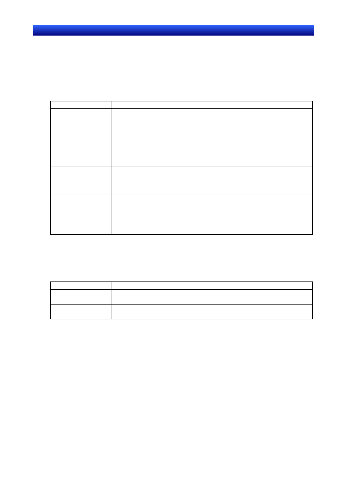
1-3-5 Screen Types and Applications
The following screens can be displayed on the PT: User screens with objects configured as required by
the user, sheets, and system screens with predefined functions.
Screen type Contents
User Screen Used to create normal screens.
Base Screen Basic screens displayed during PT operation.
Pop-up Screen Pop-up screens can be displayed overlapping other screens.
Up to 3 pop-up screens can be displayed at the same time.
Sheet Sheets are screens used when the same images are to be displayed on more than one
screen. They are used together with other screens, such as base screens and pop-up
screens.
Up to 10 sheets can be created in each project.
System Menu The System Menu Screen is predefined and cannot be changed by the user. It is used to
set or confirm various special functions of the PT, such as to initialize data or to access
various histories.
1-7
Page 22

Section 1 Overview 1-3 Basic Configuration and Functions
NS-Designer Operation Manual
1-3-6 Object Types
Some details on the types of object that can be positioned on a screen are described below.
Fixed Objects
The following fixed objects can be used.
Rectangle
Circle/Oval
Straight Line or Arrow
Polyline
Polygon
Sector
Arc
1-8
Page 23
Section 1 Overview 1-3 Basic Configuration and Functions
NS-Designer Operation Manual
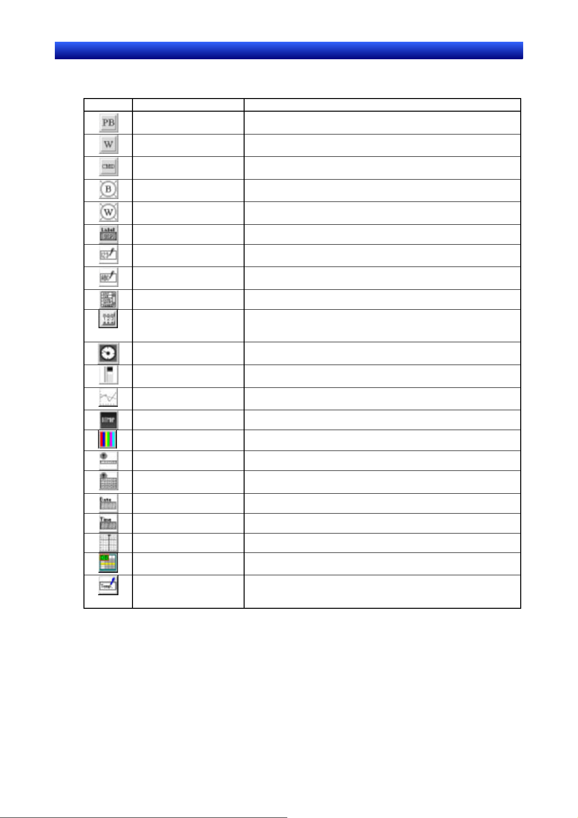
Functional Objects
The following functional objects can be used.
Icon Name Contents
ON/OFF Button Control the ON/OFF status of the specified write address. Any of four
Word Button Set numeric data at the specified address. Values can also be in-
Command Button Perform special processing, such as switching screens, controlling
Bit Lamp Turn ON and OFF according to the ON/OFF status of the specified
Word Lamp Light in 10 steps according to the value in the specified address (0 to
Text Display the registered character string.
Numeral Display & Input Numerically display the word data from the specified address and
String Display & Input Display the character string from the word data from the specified
List Selection Display the registered characters string in a list for selection.
Thumbwheel Switch Numerically display the word data from the specified address and
①
Analogue Meter Display graphs in three colors in circles, semi-circles or quarter cir-
Level Meter Display levels in three colors for the word data at the specified ad-
Broken-line Graph Display a broken-line graph for the word data at the specified ad-
Bitmap Display bitmaps.
Video Display Display images from video cameras and Vision Sensors.
Alarm/Event Display Display alarms or events that have occurred in order of priority.
Alarm/Event Summary
and History
Date Display and set date.
Time Display and set time.
Data Log Graph Display trend graphs for the word data at specified addresses.
Data Block Table Writes to and reads from PLC preset recipe data, such as instruc-
Temporary Input Display numerical values and character strings that have been input
action types can be selected.
creased and decreased.
pop-up screens, controlling video, etc.
address.
9).
input data from a tenkey pad.
address and input data from a keyboard.
increment and decrement the data when increment/decrement buttons are pressed.
cles for the word data at the specified address.
dress.
dress.
Display summaries or histories of alarms or events that have occurred.
tions for manufacturing process.
during creation of a tenkey or keyboard for Numeral Display & Input
and String Display & Input objects using command buttons.
1-9
Page 24
Section 1 Overview 1-3 Basic Configuration and Functions
NS-Designer Operation Manual
1-3-7 Functions Used to Create Screens
The following functions can be conveniently used to make screens more effective.
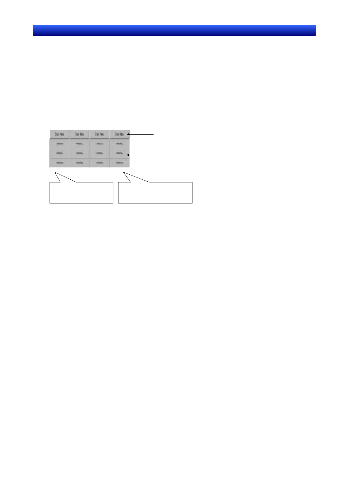
Creating Tables
Functional objects of the same type can be created as a group in a table.
Functional objects can be easily created and organized in a table simply by specifying the type of functional object, the number of rows, and the number of columns. Item names (text) can also be added to
the cells of the table.
The properties of the functional objects can be set as a group, and addresses can be automatically allocated by setting offsets.
Refer to Creating Tables under 5-1 Creating Functional Objects for more information.
Item names are created with Text objects
Functional objects: Numeral Display & Input objects
Number of horizontal items: 4
Number of vertical items: 3
Address, such as $W100,
$W101, $W102, etc., are
allocated.
Common properties for all the
Numeral Display & Input objects
are set at the same time.
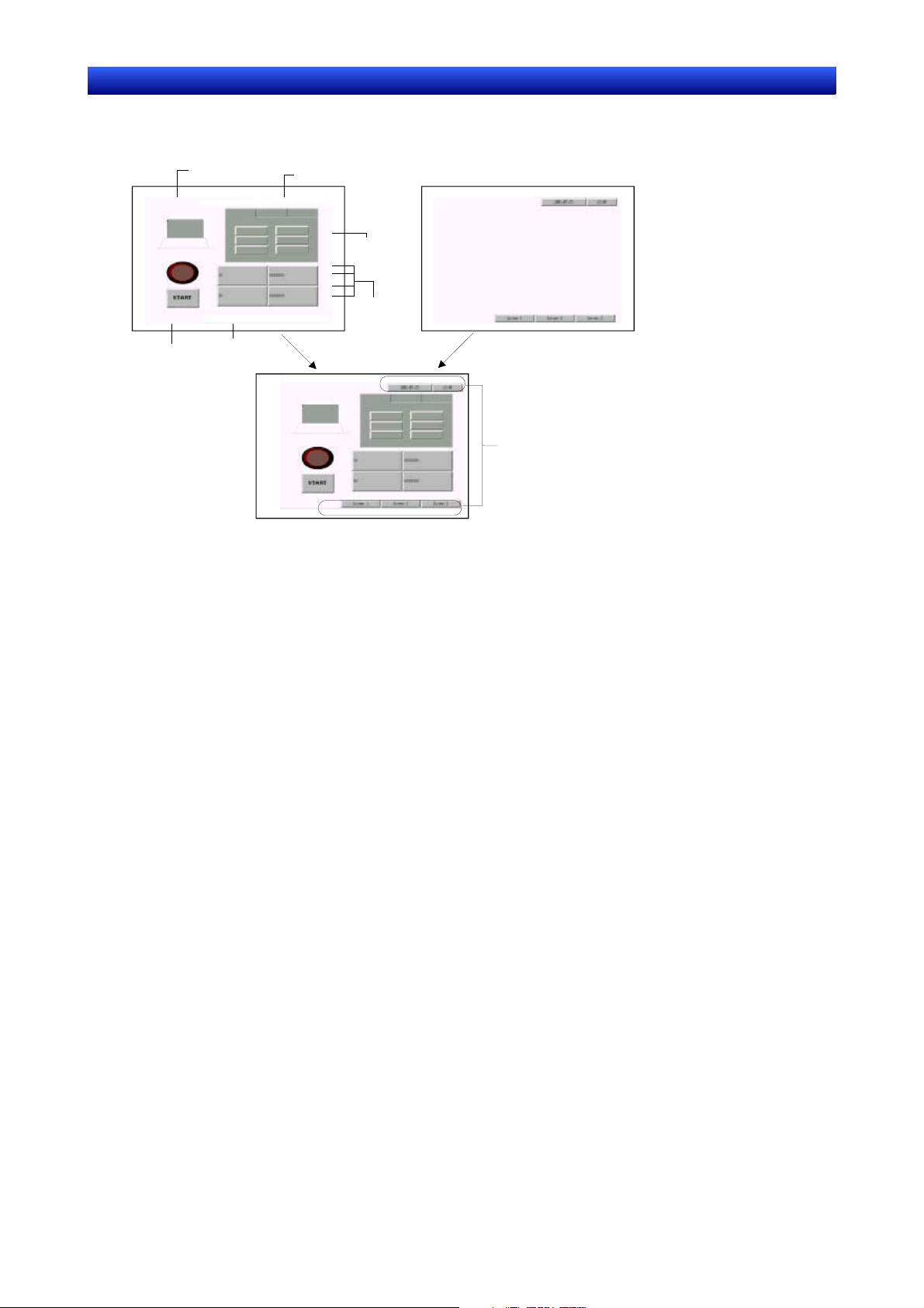
Creating Frames
A frame object enables the creation of areas on a screen so that only part of the screen can be
switched to another page. Frames consist of more than one page, and the displayed contents of the
functional objects configuring each page can be switched using the page switching function of the
frame. A frame can contain up to 256 frame pages, and objects can be pasted as required within each
frame page.
Refer to 4-4 Frames for details.
Groups
More than one functional object or fixed object can be defined as a group.
The group, which contains more than one functional or fixed object, can be rotated, flipped, or sized as
if it were just one object.
Grouped objects can also be created with other functional or fixed objects or placed in other groups.
Refer to Grouping and Ungrouping Objects under 5-5 Layout Functions for more information.
Object Library
An object and all of its property settings can be registered as one object. Created objects registered in
a library can be easily reused at many different locations or on different screens. Refer to 5-13 Library
Registration and Sharing Objects for details.
Smart Active Parts
Setting and monitor screens (such as setting screens for Position Control Units and Temperature Controllers) are pre-installed as standard library objects for the NS-Designer. For details, refer to How to
use Smart Active Parts (PDF) included with the NS-Designer.
1-10
Page 25
Section 1 Overview 1-3 Basic Configuration and Functions
NS-Designer Operation Manual
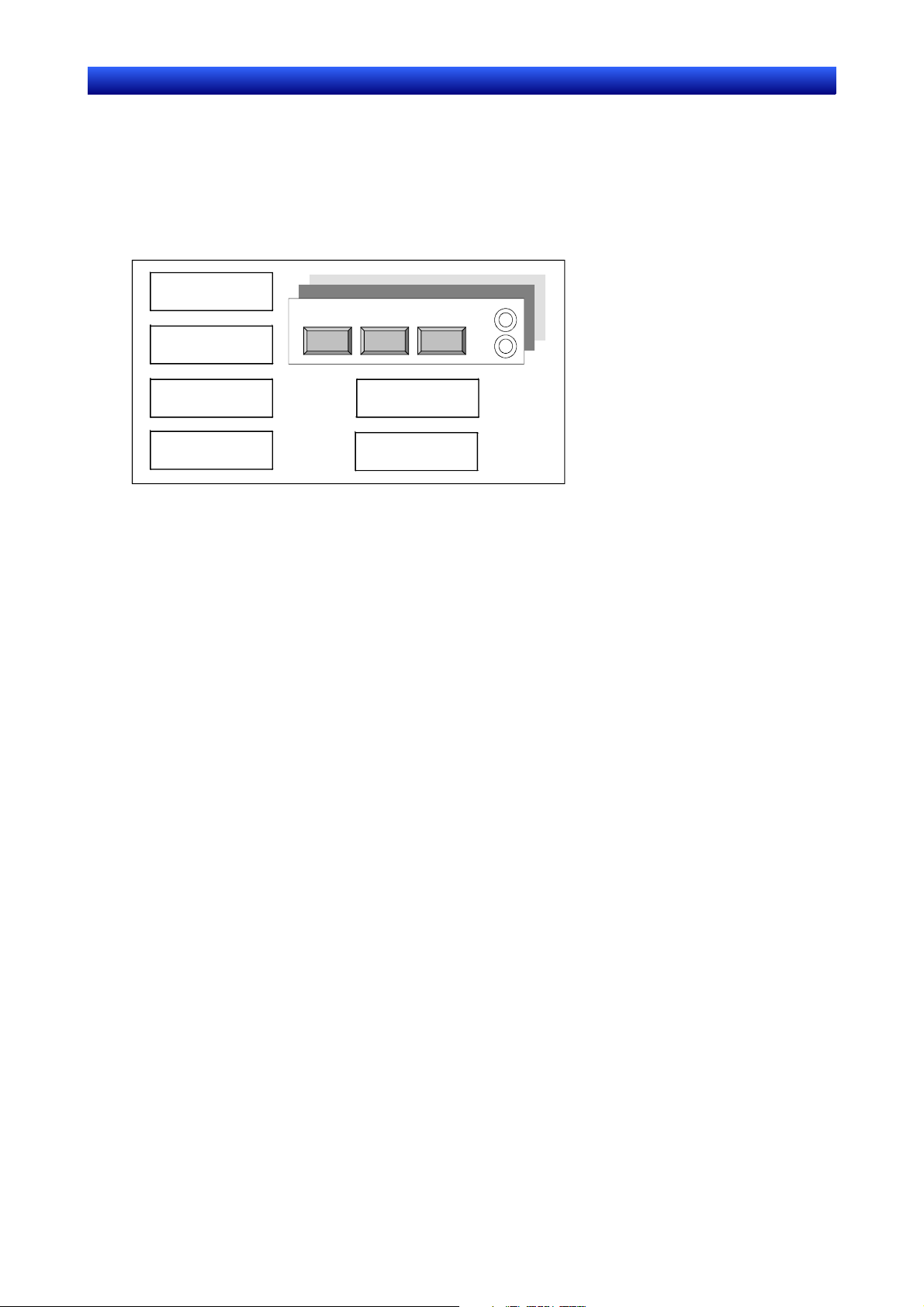
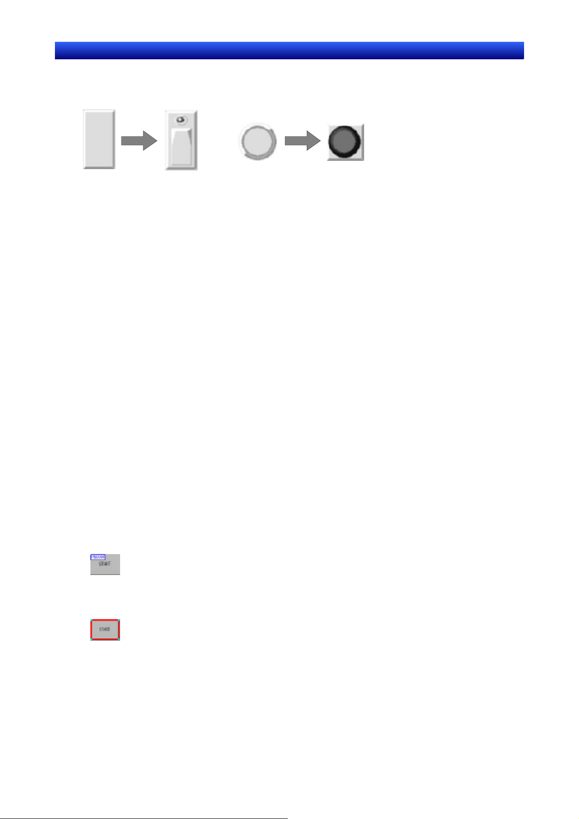
Selecting Fixed Objects for Buttons and Lamps
Specified fixed objects can be displayed for ON/OFF buttons, word buttons, bit lamps, and word lamps
to create more graphic displays.
Object
selected.
Object
selected.
Drawing Fixed Objects
Fixed objects, which do not provide any functions themselves, can be drawn on a screen. The following
fixed objects can be drawn. Rectangles, circles, ovals, straight lines, polylines, polygons, sectors, and
arcs
Creating Backgrounds
General-purpose image data can be used as backgrounds for user screens. The following file types
can be used.
•
Bitmap files (.BMP)
•
JPEG files (.JPG)
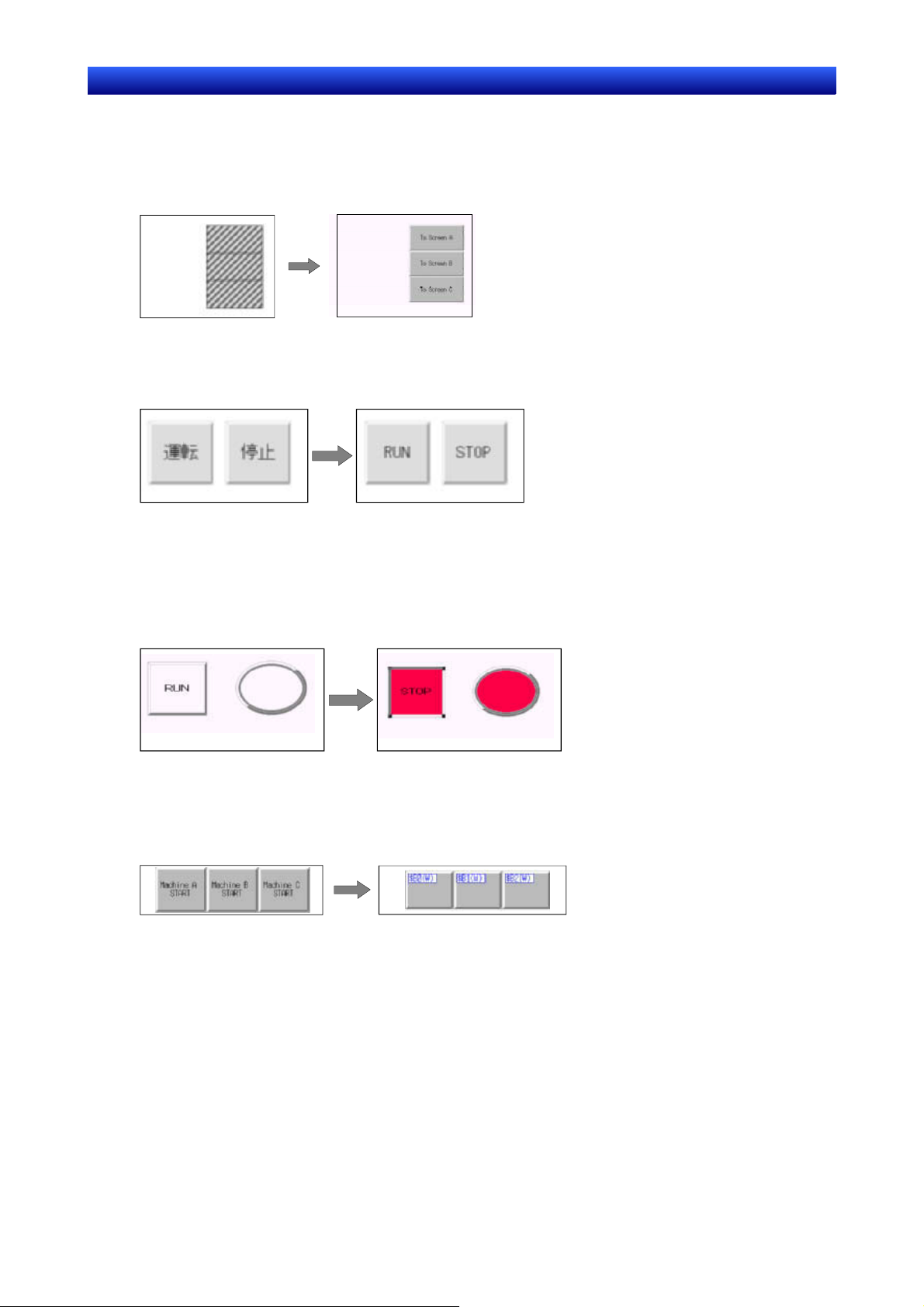
Switching Displays
Displays can be switched to check the operation of screens created offline.
The following switching functions can be used.
Switching Screens
•
Switching Frame Pages
Edited frame pages can be switched forward and backward.
Refer to Switching Frame Pages under 4-4 Frames for details.
•
Switching Screens
Edited screens can be switched forward and backward.
Refer to Switching Screens under 4-1 Basic Operations for details.
•
Zooming
Screens can be zoomed in and out.
Refer to Zoom under 4-1 Basic Operations for details.
Switching Object Displays
•
ID Displays
Object ID numbers can be displayed.
Refer to Switching Items Displayed for Objects under 4-1 Basic Operations for details.
Error Object Displays
•
Objects for which errors were detected in validating are displayed with red borders.
Refer to Show ID under 4-1 Basic Operations for details.
1-11
Page 26
Section 1 Overview 1-3 Basic Configuration and Functions
y
NS-Designer Operation Manual
Displaying Sheet Objects
•
The sheet objects overlapped on base screens can be displayed.
Refer to Show Sheet Object under Switching Items Displayed for Objects under 4-1 Basic Operations
for details.
Sheet Objects Hidden Sheet Objects Displayed
Displaying Switch Labels
•
The specified switch labels can be displayed.
Refer to Switch Label under 4-1 Basic Operations for details.
Simulating ON/OFF Status •
The functional objects can be displayed in their ON status.
Refer to Displaying ON Status under Switching Items Displayed for Objects under 4-1 Basic Opera-
tions for details.
ON Status OFF Status
Displaying Addresses
•
The communications addresses set for each functional object can be displayed. Refer to Show Address under Switching Items Displayed for Objects under 4-1 Basic Operations for details.
Normal Displa
Address Display
1-12
Page 27
Section 1 Overview 1-3 Basic Configuration and Functions
NS-Designer Operation Manual
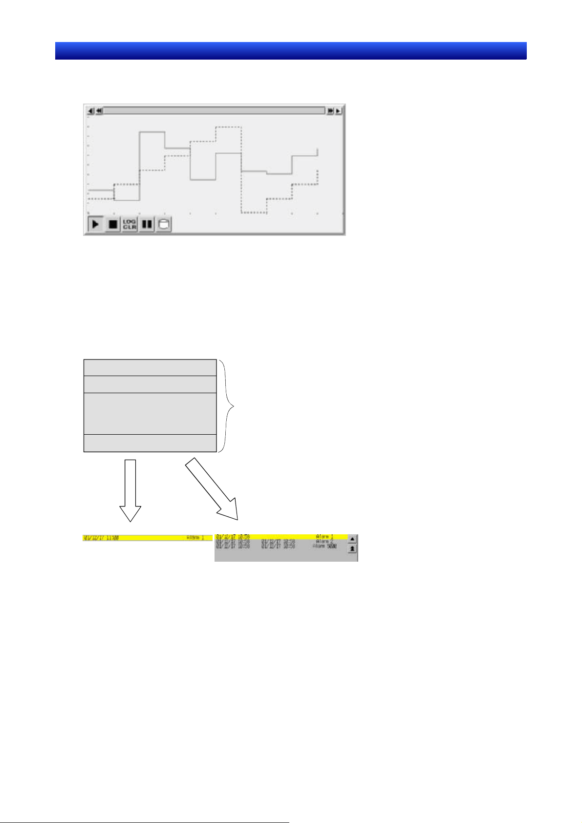
1-3-8 Data Log
The stored data for specified addresses is displayed as a graph.
Up to 100 groups can be registered for each project. Up to 16 addresses can be registered for each
group.
Up to 50 addresses can be registered for constant logging.
1-3-9 Alarms/Events
Addresses can be registered for alarm monitoring to provide notification for alarms from the specified
addresses. Registration can also be used to display events, such as operation startup.
Alarm-related functional objects can be used to display alarms and events that have occurred or to
display alarm/event histories.
Alarm 1
Alarm 2
•
•
•
•
•
Alarm 500
Up to 5,000 alarms can be registered.
Simple Display
List
1-13
Page 28
Section 1 Overview 1-3 Basic Configuration and Functions
NS-Designer Operation Manual
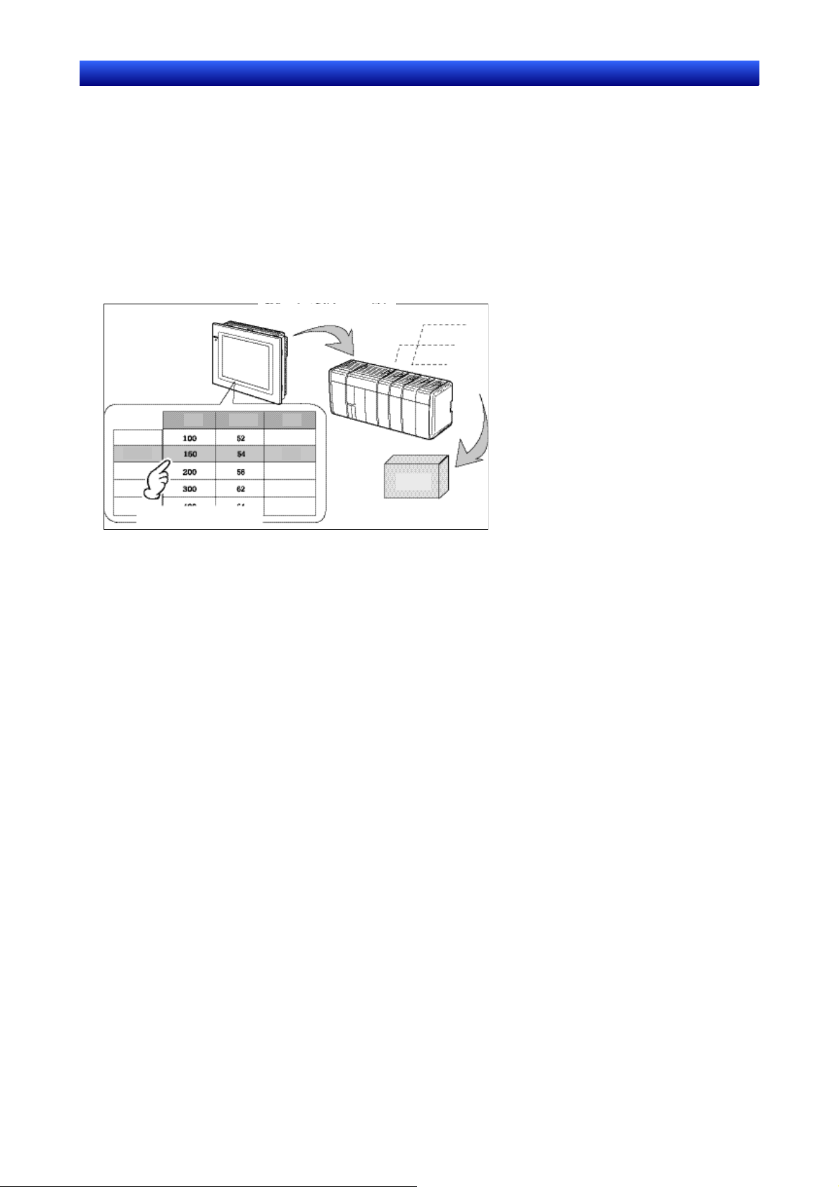
1-3-10 Data Blocks
Data blocks (recipes) enable reading/writing numeric values and character strings from/to memory areas, such as those in a PLC. Data blocks can be used to easily change the arrangement of the system.
Create the data in CSV files and store them in the PT beforehand. The created data can be used to
make changes while operating the PT.
Examples: Setting the width (numeric value), height (numeric values), and color (character string) in
the PLC (Refer to the figure shown below.)
Set width: 150, height: 54, and color: blue for product B.
Just by selecting product B, these three items can be set for the PLC. If product A is selected, a width
of 100, height setting of 52, and a color setting of red will be set for the PLC.
Data block
Product A
B
Product B
Product
Produ
Produ
Width
Conditions for product B are
selected and set in PLC.
Using data block, the user does not need to save the data in the PLC beforehand, so that memory of
the PLC can be saved and ladder program can be reduced. Data blocks also have the following features.
Data in CSV format can be edited and managed on a personal computer. •
•
Data can be edited on the PT.
•
Data can be written to a Memory Card.
•
Data can be read from a Memory Card.
•
Processes values and character strings can be handled.
•
Maximum number of rows: 1,000. Maximum number of columns: 500. Data blocks with both 1,000
rows and 500 columns, however, cannot be set.
Refer to 2-16 Data Blocks - Restrictions for Data Blocks in the Programming Manual for details.
Processing conditions for product B
(150, 54, blue) set in PLC
Height
Color
Red
Blue
Yellow
Red
Blue
To controlled devices
Product
B
1-14
Page 29
Section 1 Overview 1-3 Basic Configuration and Functions
NS-Designer Operation Manual
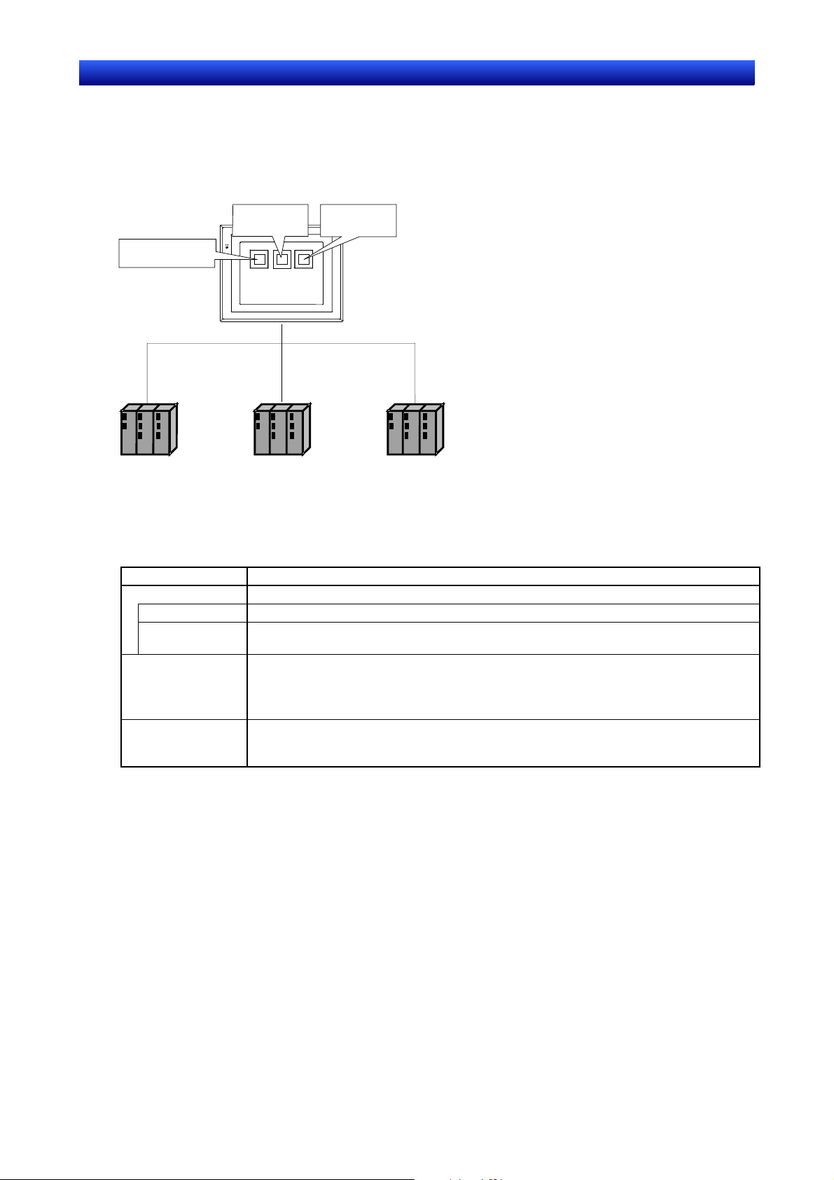
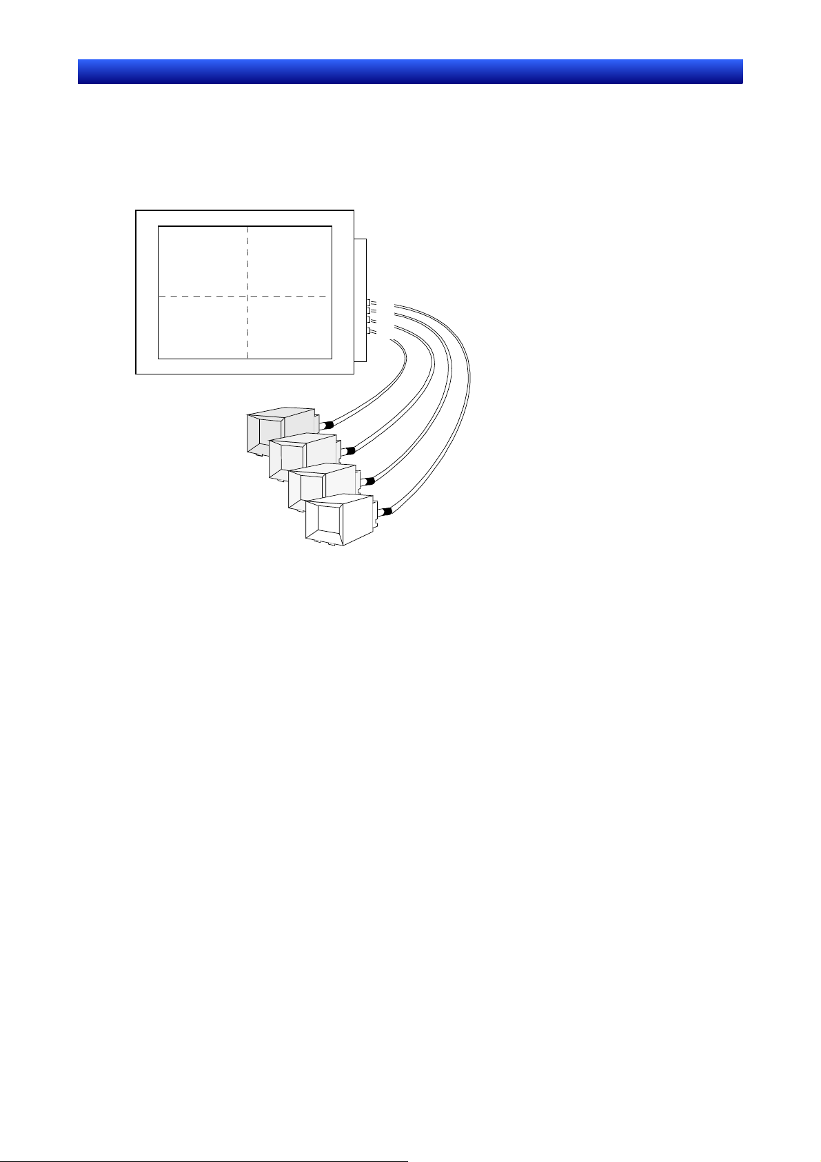
1-3-11 Video Display
Install a Video Input Unit (NS-CA001) on the PT to display the picture output from video devices such
as a video camera or Vision Sensor on the PT. Up to four video devices can be connected to the PT.
There are two input methods: NTSC and PAL.
12
34
1
2
3
4
NTSC/PAL
4 ch
3 ch
2 ch
1 ch
Video camera or
Vision Sensor
1-15
Page 30
Section 1 Overview 1-3 Basic Configuration and Functions
NS-Designer Operation Manual
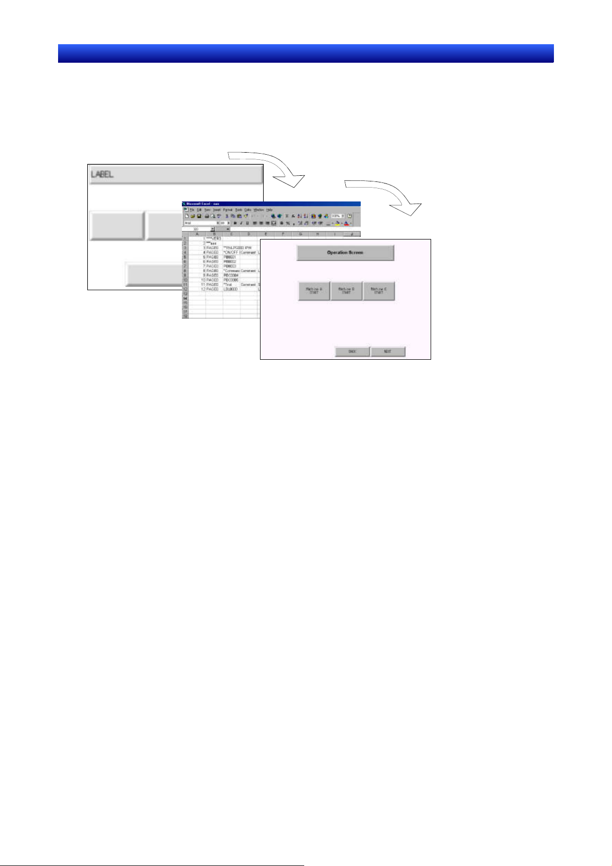
1-3-12 Importing and Exporting CSV Files
The property settings of functional objects can be edited as CSV files.
Export property settings to CSV files, edit them with a standard spreadsheet program or other editing
tool, and then import them back into the NS-Designer to set the properties of functional objects.
Refer to Section 12 Importing/Exporting CSV Files for details.
Editing in spreadsheet software
Importing
1-3-13 Validating
Functional object settings are checked according to validation items to see if any mistakes have been
made.
Any errors that are detected are displayed in a list. The functional or fixed objects where errors exist
can also be displayed.
Refer to Section 9 Validation for details.
1-16
Page 31

Section 1 Overview 1-4 Outline of Operational Flow
NS-Designer Operation Manual
1-4 Outline of Operational Flow
Screen data is created with the NS-Designer as follows:
Start NS-Designer.
Select PT model.
Open screen.
Make system settings.
Set project properties.
Set screen properties.
Register host.
Lay out objects.
Save screen data.
Save project.
Check project by printing data.
Select in dialog box.
A screen is automatically opened
when a new project is created.
Otherwise screens are opened
with
File - Open Screen
Settings - System Setting
Settings - Project Properties
Settings - Screen Properties
Settings - Register Host
File - Save Screen
File - Save Project
File - Print
Check object operation with test tool.
Transfer data to PT.
Tools - Test
File – Transfer Data
NNoottee
Note
♦ Start actual operation only after sufficiently checking the operation of the screen data and host pro-
gramming.
1-17
Page 32

Section 1 Overview 1-5 Menu Commands
NS-Designer Operation Manual
1-5 Menu Commands
The commands that appear on the pull-down menus of the NS-Designer and their functions are described in the following tables.
File Menu
Command Function
New Project Creates a new project.
Open Project Opens an existing project.
Save Project Saves the current project (overwrites the existing file).
Save Project As Saves the current project under a specified name.
Template Specifies a template project.
Project Maintenance Copies, deletes, backs up, and restores projects.
New Screen Creates a new screen under the current project.
Open Screen Opens an existing screen in the current project.
Close Screen Closes the screen currently being edited.
Save Screen Saves the current screen.
Save All Saves (overwrites) all of the data for the current project.
Open Sheet Creates new sheet or edits a sheet.
Apply Sheet Sets a screen with overlapping sheets.
Import CSV File Imports project or screen data saved in CSV format to the current project or
screen.
Export CSV File Exports the current project or screen data to a file in CSV format.
Transfer Data Downloads screen data created on the NS-Designer to the PT or uploads screen
data from the PT to the NS-Designer.
Print
Recent Projects Displays a list of currently edited projects. (Up to four projects are displayed.)
Exit Ends the NS-Designer.
Edit Menu
Command Function
Undo Discards changes and restores the previous status.
Redo
Cut Deletes the selected objects and places them in the internal buffer.
Copy Copies the selected objects and places them in the internal buffer.
Paste Pastes objects that have been cut or copied.
Offset Paste Pastes objects that have been cut or copies with offset addresses.
Delete Deletes the selected objects.
Find Searches for functional objects using addresses or character strings as keywords.
Replace Replaces addresses set for functional objects.
Select All Selects all objects on a screen or all functional or fixed objects of a specific type.
Repeat Copies the specified object the specified number of times horizontally or vertically.
Outputs current project or screen information to a printer or to a file. Select Print
to display a preview.
Restores the changes discarded with Undo.
1-18
Page 33

Section 1 Overview 1-5 Menu Commands
NS-Designer Operation Manual
View Menu
Command Function
Toolbars Displays and hides the toolbars.
(Standard, functional object, fixed object, operation, formatting, color, and address
settings)
Status Bar Displays and hides the status bar.
Switch Label Switches to the specified label display.
Previous Screen Displays the previous screen.
Next Screen Displays the next screen.
Previous Frame Page Displays the previous frame page.
Next Frame Page Displays the next frame page.
Simulate ON/OFF Switches functional objects between ON and OFF status displays.
Show ID Displays and hides ID numbers for objects.
Show Address Displays and hides address displays for functional objects.
Show Error Object Displays and hides error marks for objects.
Show Sheet Object Switches the display of objects registered in sheets.
Show Touch Points Displays the touch points on the PT.
Zoom Zooms the display in and out.
Refresh Redraws the screen.
Functional Objects Menu
Command Function
ON/OFF Button Starts creation of an ON/OFF button.
Word Button Starts creation of a word button.
Command Button Starts creation of a command button.
Bit Lamp Starts creation of a bit lamp.
Word Lamp Starts creation of a word lamp.
Text Starts creation of text.
Numeral Display & Input Starts creation of a number display and input object.
String Display & Input Starts creation of a string display and input object.
List Selection Starts creation of a list selection object.
Thumbwheel Switch Starts creation of a thumbwheel switch.
Analogue Meter Starts creation of an analogue meter.
Level Meter Starts creation of a level meter.
Broken-line Graph Starts creation of a broken-line graph.
Bitmap Starts creation of a bitmap.
Alarm/Event Display Starts creation of an alarm/event display object.
Alarm/Event Summary &
History
Date Starts creation of a data object.
Time Starts creation of a time lamp.
Data Log Graph Starts creation of a data log graph.
Data Block Table Starts creation of a data block table.
Video Display Starts creation of a video display.
Frame Starts creation of a frame region.
Table Starts creation of a table on a table creation screen.
Temporary Input Starts creation of a temporary input.
Starts creation of an alarm/event summary & history.
1-19
Page 34

Section 1 Overview 1-5 Menu Commands
NS-Designer Operation Manual
Fixed Objects Menu
Command Function
Rectangle Starts creation of a rectangle.
Circle/Oval Starts creation of a circle or oval.
Straight line Starts creation of a straight line.
Polyline Starts creation of a continuous straight line.
Polygon Starts creation of a polygon.
Sector Starts creation of a pie-shaped sector.
Arc Starts creation of an arc.
Settings Menu
Command Function
Object Properties Sets the properties of the selected functional object.
Edit Label Enables direct editing of labels on the screen without opening a property dialog
box.
Change Settings at Once Enables editing the basic properties of the selected functional objects in a table.
Functional objects can be added and deleted as well.
Flicker Setting Sets the flicker operation parameters.
Password Setting Sets the password.
Unit/Scale Setting Displays the unit and scale conversions for a numeral display.
Alarm/Event Setting Set the alarm function (addresses, messages, etc.).
Data Log Setting Set the data log function (e.g., data log groups).
Data Block Setting Performs registration and correction of data blocks.
Change Input Order Sets the order for shifting the focus for objects that can be input.
Project Properties Sets the project properties.
Screen Properties Sets the screen properties.
System Setting Sets the PT operating parameters.
Reset Defined Default Resets all of the settings made for an object. (Functional and fixed objects)
Change PT Model Sets the model of the NS-series PT.
Register Host Registers the host.
Layout Menu
Command Function
Align/ Distribution Aligns the position of more than one selected object. (Left, Center in a Column,
Right, Top, Center in a Row, Bottom, Distribute Horizontally, or Distribute Verti-
cally)
Make Same Size Sizes all selected objects horizontally and vertically to the same size as that of the
largest or smallest object.
Order Moves the selected object to the front or back.
Nudge Moves the selected object one bit or one grid unit up, down, right, or left.
Rotate/Flip
Modify Edits the shape of a fixed object. (Edits, adds, or deletes nodes.)
Group Groups objects.
Ungroup Ungroups a group of objects.
Grid Sets the grid.
Rotates or flips an object. (90 Degrees Clockwise, 90 Degrees Counterclockwise,
Flip Vertical, Flip Horizontal, Rotate Right 90 Degrees Around Center of
Screen/Frame, Rotate Left 90 Degrees Around Center of Screen/Frame, Flip
Horizontal Around Center of Screen/Frame, or Flip Vertical Around Center of
Screen/Frame)
1-20
Page 35

Section 1 Overview 1-6 Functions Added in Version 3.0
NS-Designer Operation Manual
Tools Menu
Command Function
Screen Maintenance Changes the titles of, copies, deletes, or replaces screen page numbers for
screens in a project.
Sheet Maintenance Changes the titles of, copies, deletes, or replaces sheet page numbers for sheets
in a project.
Validation Performs an error check on object settings.
Validation Result Displays the results of validation.
Functional Object List Displays a list of functional objects on screen with property settings.
List Up Functional Objects
Used
List Up Addresses Used Displays a list of addresses that are used.
Address Cross Reference Displays a list of functional object IDs when addresses are used.
Edit Background Bitmap Edits the background.
Register Library Registers functional objects in the library and performs maintenance.
Use Library Paste functional objects registered in the library.
Test Performs operating test on the computer without connecting to a PLC.
Resource Report Displays a report on the resources that have been used.
Options Sets optional functions.
Displays the number of times functional objects are used in screens, screen
pages that are not used, and frame pages in a tree format.
Window Menu
Command Function
Cascade Cascades the screen editing windows.
Tile Tiles the screen editing windows.
Arrange Icons Arranges the minimized window icons.
Help Menu
Command Function
Contents Displays the contents for the online help.
Search for Help on Displays a search dialog box for help topics.
How to Use Help Displays information on using Help.
About NT631
Conversion Support Tool
Displays information on the version of NS-Designer.
1-6 Functions Added in Version 3.0
The NS-Designer Version 3.0 is supplemented and enhanced by the following functions.
Supplement/
Enhancement
Screen data transfer
through PLCs
Switch Box Screen Displays I/O status of addresses on the NS Hardware. Addresses and their
Multiple language support Multiple languages (Simplified Chinese, Korean, Traditional Chinese, etc.) can
Video capture using a PLC
trigger
Enhanced parts List Vastly increased library objects for use as buttons and lamps.
Reading CLK status Displays status of CLK Board attached with NS Hardware on the screen.
Macro to set time Automatically sets the time, which as set manually before.
Screen data can be
transferred using Ethernet
directly the first time
Enables transferring screen data to NS Hardware through a PLC and
transferring ladder program to the PLC through the NS Hardware.
comments can be reused from a ladder program using the Switch Box Utility.
be displayed on user screens.
Enables performing video captures using system memory ($SW24) as a trigger.
Screen data can be transferred using Ethernet directly the first time.
1-21
Function
Page 36

Section 1 Overview 1-7 Functions Added in Version 4.0
NS-Designer Operation Manual
1-7 Functions Added in Version 4.0
The NS-Designer Version 4.0 is supplemented and enhanced by the following functions.
Supplement/
Enhancement
Equipped with USB port as
a standard feature.
Display possible in up to
32,000 colors.
Screen data capacity
greatly increased.
High-speed drawing The drawing speed is twice that of existing OMRON products.
Equipped with a USB port as a standard feature enabling display contents to be
printed using USB-compatible general-purpose color printers (e.g., Canon or
Epson printers).
BMP and JPEG images can now be displayed using up to 32,000 colors.
The data capacity has increased from 4 Mbytes to 20Mbytes.
Function
1-8 Functions Added in Version 5.0
The NS-Designer Version 5.0 is supplemented and enhanced by the following functions.
Supplement/
Enhancement
NS5-series models added. Added NS5-SQ0 (B) -V1 with compact 5.7-inch STN color display.
Object forms can be
selected by user.
Windows fonts can be
used in Button and Lamp
objects.
Continuous input can be
received from Bar Code
Reader.
Ver. 1.X projects can be
created and edited.
The forms of ON/OFF Button, Word Button, Bit Lamp, and Word Lamp objects
can now be specified as BMP or JPEG image files.
The labels used in ON/OFF Button, Word Button, Bit Lamp, Word Lamp, and
Command Button objects can now be specified using Windows fonts.
Input order of numeric values and character strings can now be controlled,
allowing continuous input from a bar code reader.
NS-Designer Ver. 5.0 can be used to create and edit projects for NS System Ver.
1.X.
Function
1-9 Functions Added in Version 6.0
The NS-Designer Version 6.0 is supplemented and enhanced by the following functions.
Supplement/
Enhancement
A PT model added. Added NS8-TV1 (B)-V1.
Transfer program functions
added.
Data log function
expanded.
Video captures can be
read from the memory
card.
Appearance of command
buttons can be specified.
Temporary input object
added.
The storage format of
numeric values in system
memory can be selected.
Screen data can be transferred from a personal computer to the PT via modem.
Installing a CLK board in the personal computer enables screen data to be
transferred. CX-Server compatibility has also simplified settings required for data
transfer.
The number of always logging points has been increased from 5,000 to 50,000
points, and logging data can be automatically saved to the memory card. Saved
CSV files can be read and displayed overlapping the log graph with a reference.
Image data saved in the memory card can be specified from a list and displayed.
The list can be called using the command buttons or from the system menu.
The appearance of command buttons can be specified as round buttons. BMP
and JPEG image files can be specified for button appearance. Write confirmation
messages can also be set.
Objects for temporarily displaying input numerical values or character strings are
provided for use when creating tenkeys or keyboards for Numerical Display &
Input and String Display & Input objects using command buttons. Temporary
input objects can also be used to display maximum and minimum values.
The numerical value storage format for system memory can be selected from
BCD and binary.
Function
1-22
Page 37

Section 1 Overview 1-10 Functions Added in Version 6.2
NS-Designer Operation Manual
Supplement/
Enhancement
The data format for
specifying line numbers in
indirectly specified files for
functional objects can be
selected.
The number of alarms has
been increased.
Macros FOR, NEXT,
CONTINUE, and BREAK
have been added.
Label application function
for importing CSV files has
been added.
System memory functions
have been added.
The data format for specifying line numbers in indirectly specified files set using
functional object properties can be selected from BCD and binary.
The maximum number of alarms that can be registered has been increased to
5,000.
Loop processing can be performed using macros. This improves efficiency of
macro creation.
When importing CSV files, the character properties for a specified label name
can be applied to the character properties for another label. This function is
useful when setting multiple labels.
The following flags have been added:
PT battery low flag
PT memory card free space check flag
Memory card power OFF bit
Memory card removing status
Video capture start bit
Video capture executing flag
Video capture results flag
Periodical Data Log Save in process flag
Print screen/video capture switching bit
Function
1-10 Functions Added in Version 6.2
The NS-Designer Version 6.2 is supplemented and enhanced by the following main functions.
Supplement/
Enhancement
PT models added Added NS5-SQ0-V2, NS5-TQ0-V2, and NS5-MQ0-V2.
Project trigger macro
added
Data block control
functions added to
command buttons
Added items to system
memory
Added arrows Arrow heads can be added to the start and/or end of straight lines.
Expanded Alarm/Event
Summary & History
Added program transfer
function
Added installation method NS-Designer can be installed from the CX-One FA Integrated Tool Package.
Added startup method Startup has been enabled by right-clicking the NS-series PT in the CX-Integrator
Setting the macro to execute when the bit or value at a specified address
changes has been enabled.
Data block control functions have been added to command buttons to enable
reading/writing between CSV files and PLC memory, CVS files and PT memory,
and PT memory and PLC memory when a button is pressed or a specified
address turns ON while the command button is displayed.
The following have been added to system memory: data block control complete
flag, internal holding bit/word memory ($HB/$HW) initialization flag, and data
block error number.
The titles of each display item can now be displayed on the top line. Also, alarm
messages that are not completely displayed can be touched to display them in a
message box.
Screen data transfer to the PT from a personal computer has been enabled
using a USB cable.
Network Configuration Window and selecting Start Special Application. If Start
with Settings Inherited is selected, startup through to new project creation will be
automatically executed.
Function
1-23
Page 38

Section 2 Setup, Starting, and Exiting
NS-Designer Operation Manual
Section 2 Setup, Starting, and Exiting
The NS-Designer software must be installed in the computer when using the NS-Designer for the first time.
The NS-Designer is application software designed to be operated on Microsoft Windows 95, 98, NT, Me, 2000, or
XP.
Use the following procedure to install, start, and exit the NS-Designer when Microsoft Windows 95, 98, NT, Me,
2000, or XP is already installed in the computer.
2-1 Before Installing the NS-Designer...............................................................................................................2-1
2-2 Installing the NS-Designer...........................................................................................................................2-2
2-3 Starting the NS-Designer ........................................................................................................................... 2-14
2-4 Exiting the NS-Designer ............................................................................................................................2-15
2-5 User Interface.............................................................................................................................................2-16
Page 39

Section 2 Setup, Starting, and Exiting 2-1 Before Installing the NS-Designer
r
r
NS-Designer Operation Manual
NS-Designer Operation Manual
2-1 Before Installing the NS-Designer
Before installing the NS-Designer, check that the following requirements have been met.
Monito
g
VGA monitor or better.
Resolution of 800 x 600 pixels or higher is
recommended for optimum use of NSDesigner.
System Requirements
CPU Intel Celeron 400 MHz or better •
•
Recommended memory 64 Mbytes or more
•
Hard disk 200 Mbytes or more available disk space
•
Internet Explorer Version 5.5 or higher
Compute
g
IBM PC/AT or compatible with Microsoft Windows 95, 98, NT 4.0 (SP6a
or higher), Me, 2000 (SP3 or higher), or XP installed
CD-ROM Drive
g
Required to install the
NS-Designer.
Mouse
g
A mouse that supports
Microsoft Windows.
2-1
Page 40

Section 2 Setup, Starting, and Exiting 2-2 Installing the NS-Designer
NS-Designer Operation Manual
NS-Designer Operation Manual
2-2 Installing the NS-Designer
Install the NS-Designer in the hard disk.
To install the NS-Designer, execute the installation program provided.
For details on procedures for installing the NS-Designer from CX-One FA Integrated Tool Package, refer to the CX-One Setup Manual provided with CX-One.
Cat. No. Model Manual name Contents
W444
CXONE-AL@@C-E
RReeffeerreennccee
Reference
♦
If the NS-Designer was previously installed from the CX-One and it’s necessary to install it from the
individual NS-Designer CD-ROM, always uninstall the NS-Designer using the following procedure
before installing it from its individual CD-ROM. The NS-Designer will not operate properly if it is
installed without first uninstalling it.
1. Insert the CX-One installation disk 1 into the CD-ROM drive.
2. Select the Modify Option to enable modifying the Support Software that is installed.
3. In the Select Features Dialog Box, clear the selection of only the NS-Designer. Do not change
4. Continue by following the instructions in the dialog boxes to modify the installation and uninstall
5. Once the NS-Designer uninstallation process has been completed, place the individual CD-ROM
Note: If the version of the CX-Server bundled on the individual NS-Designer CD-ROM is lower than
any other selections.
NS-Designer.
disk for the NS-Designer into the CD-ROM drive and install the NS-Designer. (See note.)
the version of the CX-Server bundled with the CX-One, install only the NS-Designer and NOT
the CX-Server. (A message will be displayed if the version is lower.) If a version of CX-Server
that is lower than the version with the CX-One is installed, the CX-One will not operate properly.
CX-One Setup Manual Installation and overview of CX-One FA
Integrated Tool Package.
2-2-1 Basic Installation Operations
The main buttons that are displayed during installation are as follows:
Confirms the settings in the window displayed and moves to the next window.
Cancels the settings in the window displayed and returns to the previous window.
Closes the window currently being displayed. The settings in the window are cancelled.
Installation can be cancelled by pressing this button in the installation window. A confirmation message
will be displayed.
The actual folder configuration is displayed in a tree format, from which the folders where installation
files are to be installed can be selected.
2-2
Page 41

Section 2 Setup, Starting, and Exiting 2-2 Installing the NS-Designer
NS-Designer Operation Manual
NS-Designer Operation Manual
2-2-2 Installation Procedure
1. Start up Windows 95, 98, NT, Me, 2000, or XP.
2. Close all applications before executing installation. Place the NS-Designer CD-ROM in the
CD-ROM drive. The setup program is started automatically. If the setup program does not start
automatically, such as after executing uninstall, locate Setup.exe in the CD-ROM using Windows
Explorer, and then double-click the file to execute the setup program.
RReeffeerreennccee
Reference
♦ If NS-Designer Ver. 2.X, 3.X, 4.X, 5.X, or 6.X is already installed, a dialog box to confirm deletion of
this version will be displayed. Click the OK Button to start deleting this version. To exit the setup
program, click the Cancel Button and then click the Exit Button.
FinsGateway and CX-Server will not be uninstalled by this operation.
3. The NS-Designer Setup Wizard will be displayed.
Install the NS-Designer by following the instructions in the Setup Wizard.
4. During installation, the installation progress is displayed as a percentage.
5. When NS-Designer installation has been completed, a message to confirm installation of Smart
Active Parts will be displayed. Click the Yes Button to start the installation. If Smart Active Parts
installation is not required, click the No Button and proceed to step 10.
Smart Active Parts are libraries containing setting/monitoring screens (e.g., Position Control Unit
setting screens and Temperature Controller monitoring screens).
6. The following dialog box will be displayed. Click the Next Button.
2-3
Page 42

Section 2 Setup, Starting, and Exiting 2-2 Installing the NS-Designer
NS-Designer Operation Manual
NS-Designer Operation Manual
7. The Setup Type Dialog Box will be displayed. Select the setup type and click the Next Button. If
Complete is selected, proceed to step 9.
8. The dialog box for selecting features will be displayed. Select the Smart Active Parts to be installed
and click the Next Button.
9. During installation, the installation progress is displayed as a percentage. When installation has
been completed, the following dialog box will be displayed. Click the Finish Button.
10. A message will be displayed to confirm installation of the CX-Server. Click the Yes Button.
11. The following screen for installing the CX-Server will be displayed.
2-4
Page 43

Section 2 Setup, Starting, and Exiting 2-2 Installing the NS-Designer
NS-Designer Operation Manual
NS-Designer Operation Manual
12. Click the Next Button. The screen for specifying the installation destination will be displayed.
13. Click the Next Button. If the following message is displayed, click the OK Button to continue in-
stallation.
CX-Server installation followed by installation of CX-Server Driver management tools will begin,
and the installation program will automatically copy the CX-Server and CX-Server Driver management tools files to the specified directory.
14. When installation has been completed, the following dialog box will be displayed. Select whether or
not to restart the computer immediately, and click the Finish Button to complete the installation.
Always restart the computer before using NS-Designer.
RReeffeerreennccee
Reference
♦
When installing NS-Designer in Windows NT, 2000, or XP, log onto the computer as the administrator to ensure that system DLL files can be overwritten. If overwriting system DLL files fails,
NS-Designer may not operate properly.
♦
When adding Smart Active Parts after installation of NS-Designer, double-click the CD-ROM directory \SmartActiveParts\Setup.exe from Windows Explorer to execute the setup program. Select all
the Smart Active Parts to be used in the dialog box for selecting components.
♦
Refer to the How to manage after conversion file in the Programs Folder under the Windows Start
Menu for details after NT31C/NT631C Conversion Support Tool conversion.
♦
Internet Explorer Ver 5.5 or higher is required to transfer data.
2-5
Page 44

Section 2 Setup, Starting, and Exiting 2-2 Installing the NS-Designer
NS-Designer Operation Manual
NS-Designer Operation Manual
The folder structure after installation is as follows:
NS-Designer
bldparts
intaparts
BMP files Parts Collection (bitmaps)
Manual Directory containing manuals
Sample Project Data Sample project data for tutorial
Tutorial Tutorial manual
Macro Macro reference
Operation Operation manual
Setup Setup manual
Programming Programming manual
Smart Active Parts How to use Smart Active Parts
Host Connection
RGB_Video (NS-CA002) NS-CA002 RGB/Video Input Unit Manual
PartsLib
Smart Active Parts Smart Active Parts for NS8/NS10/NS12
Smart Active Parts Mini Smart Active Parts for NS5
runparts
System Backup
NS12_V1
V6_2 Ver. 6.2 system program for NS12-V1
NS12
V3_x Ver. 3.x system program for NS12
NS10_V1
V6_2 Ver. 6.2 system program for NS10-V1
NS10
V3_x Ver. 3.x system program for NS10
NS8_V1
V6_2 Ver. 6.2 system program for NS8-V1
NS7
V3_x Ver. 3.x system program for NS7
NS5_V1_V2
V6_2 Ver. 6.2 system program for NS5-V1/V2
RecoverUpdate_6_2 Ver. 6.2 recovery/update program
RecoverUpdate_3_x Ver. 3 recovery/update program
NT631C_Cnv Directory containing NT31C/NT613C Conversion Support Tool
Readme_E.txt Please read. (Contains precautionary information.)
Host Connection Manuals (Temp. Controller and Memory Links/Host Links)
2-6
Page 45

Section 2 Setup, Starting, and Exiting 2-2 Installing the NS-Designer
NS-Designer Operation Manual
NS-Designer Operation Manual
2-2-3 Uninstalling
1. When uninstalling the NS-Designer or CX-Server, click the Windows Start Button and select Set-
tings - Control Panel.
2. Double-click Add/Remove Applications.
2-7
Page 46

Section 2 Setup, Starting, and Exiting 2-2 Installing the NS-Designer
NS-Designer Operation Manual
NS-Designer Operation Manual
3. Select NS-Designer or CX-Server from the displayed list of applications, and click the
Add/Remove Button.
4. When the NS-Designer has finished being uninstalled, a message will be displayed indicating that
the uninstall operation has been completed. Check the message and then click the OK Button.
2-8
Page 47

Section 2 Setup, Starting, and Exiting 2-2 Installing the NS-Designer
NS-Designer Operation Manual
NS-Designer Operation Manual
2-2-4 Installing USB Drivers for NS-Series PTs.
Install the NS-series USB driver in the personal computer. After installation, data can be transferred
between the personal computer and NS-series PT via USB.
RReeffeerreennccee
Reference
♦ With NS-V1 Series models, make sure that the PT has a lot number that supports USB transmis-
sion. The system program version of the NS-series PT must also support USB transmission. For
details, refer to 3-3-2 Connecting via USB in the NS series Setup Manual (Cat. No. V083).
Compatible Personal Computers
Windows 98, Windows Me, Windows 2000, and Windows XP
Operation Procedure
Windows 2000 and Windows XP:
1. Start Windows 2000 or Windows XP.
2. Connect the personal computer to the NS-series PT USB slave connector using the USB cable.
The following Add New Hardware Wizard will be displayed. Click the Next Button.
3. The following dialog box will be displayed. Select Search for the best driver for my device (Rec-
ommended). Click the Next Button.
4. Select Specify a location only and then click the Next Button.
2-9
Page 48

Section 2 Setup, Starting, and Exiting 2-2 Installing the NS-Designer
NS-Designer Operation Manual
NS-Designer Operation Manual
5. Click the Browse Button, and specify the following file.
NS-Designer installation directory
\USBHostDriver\Win2k_XP\Omron_NS.inf
6. Click the OK Button to display the following dialog box. Click the Next Button to start installing the
USB driver.
7. When installation is completed, the following dialog box will be displayed. Click the Finish Button.
2-10
Page 49

Section 2 Setup, Starting, and Exiting 2-2 Installing the NS-Designer
NS-Designer Operation Manual
NS-Designer Operation Manual
Windows 98 and Windows Me:
1. Start Windows 98 or Windows Me.
2. Connect the personal computer to the NS-series PT USB slave connector using the USB cable.
The following Add New Hardware Wizard will be displayed. Click the Next Button.
3. The following dialog box will be displayed. Select Search for the best driver for your device
(Recommended). Click the Next Button.
4. Select Specify a location only and then click the Browse Button and specify the following file.
NS-Designer installation directory
\USBHostDriver\Win98_Me\NS_DEV.inf
5. Click the Next Button.
2-11
Page 50

Section 2 Setup, Starting, and Exiting 2-2 Installing the NS-Designer
NS-Designer Operation Manual
NS-Designer Operation Manual
6. Click the Next Button to start installation.
When installation is completed, the following dialog box will be displayed. Click the Finish Button.
7. The Add New Hardware Wizard will be displayed again. Click the Next Button.
8. The following dialog box will be displayed. Check that Search for the best driver for your device
(Recommended) is selected, and then click the Next Button.
9. Select Specify a location only and then click the Browse Button and specify the following file.
NS-Designer installation directory
\USBHostDriver\Win98_Me\NS_COM.inf
10. Click the Next Button.
2-12
Page 51

Section 2 Setup, Starting, and Exiting 2-2 Installing the NS-Designer
NS-Designer Operation Manual
NS-Designer Operation Manual
11. Click the Next Button to start installation.
When installation is completed, the following dialog box will be displayed. Click the Finish Button.
2-13
Page 52

Section 2 Setup, Starting, and Exiting 2-3 Starting the NS-Designer
NS-Designer Operation Manual
NS-Designer Operation Manual
2-3 Starting the NS-Designer
To start the NS-Designer, click the Windows Start Button, and then select Programs - Omron –
CX-One - NS-Designer - NS-Designer Ver X (The items displayed may vary according to the program
folder specified during installation.), right-click the NS-series PT in the Network Configuration Window
of CX-Integrator, and select Start Special Application - Start Only.
When the NS-Designer startup is completed, the Main Window will be displayed, as follows:
RReeffeerreennccee
Reference
♦ More than one copy of the NS-Designer application can be run at the same time.
♦ To start NS-Designer, log in as the administrator when using a personal computer running Windows
NT, 2000, or XP.
2-14
Page 53

Section 2 Setup, Starting, and Exiting 2-4 Exiting the NS-Designer
NS-Designer Operation Manual
NS-Designer Operation Manual
2-4 Exiting the NS-Designer
Use one of the following operations to exit the NS-Designer.
Select Exit from the File Menu. •
•
Click the Close Button at the top right of the Main Window.
•
Double-click the NS-Designer icon at the top left of the Main Window.
•
Click the NS-Designer icon at the top left of the Main Window and select Close from the Control
Menu Box.
•
Press the Alt + F4 Keys.
If the project data that is open has not been saved, a confirmation message will be displayed.
When the NS-Designer is exited, the system will return to the Windows screen.
2-15
Page 54

Section 2 Setup, Starting, and Exiting 2-5 User Interface
r
NS-Designer Operation Manual
NS-Designer Operation Manual
2-5 User Interface
2-5-1 Basic Screen Functions
The configuration and names and functions of the components in the NS-Designer operation screen
are described here.
Title Bar
The title bar displays the application name, project name, and screen number.
Menu Bar
Separates the functions into related groups.
Each group name is displayed in the menu bar and the functions are displayed in pull-down menus
under each group name.
Toolbars
Title ba
Menu bar
Toolbars
Screen being
created
Status bar
Standard Toolbar
This toolbar displays frequently used functions as icons.
Create
New
Project
Open
Project
Save
Project
Screen
Create
New
Screen
Open
Cut Paste Redo
Save
Screen
Copy Undo
Zoom
About
NS-Designer
2-16
Page 55

Section 2 Setup, Starting, and Exiting 2-5 User Interface
j
r
r
NS-Designer Operation Manual
NS-Designer Operation Manual
Functional Objects Toolbar
Displays screen creation functions for functional objects as icons. Select the icon button of the functional object to be used in creating the screen to start screen creation.
ON/OFF
Button
Bitmap
Word
Button
Command
Button
Alarm/Event
Summary &
History
Alarm/Event
Display
Bit
Lamp
Date
Word
Lamp
Time
Data Log
Graph
Text
Numeral
Display &
Data Block
String Display
& Input
Input
Ta bl e
Video Display
List
Selection
Temporary
Thumbwheel
Switch
Analogue
Meters
Input
Frame
Level
Meter
Broken-line
Ta bl e
Graph
Fixed Objects Toolbar
Displays fixed object drawing functions as icons. Select the icon button for the fixed object to be drawn
and start drawing.
Circle/Oval
Straight
Line
Polyline Sector
Poly gon Arc
Rectangle
Operations Toolbar
Displays frequently used functions from the View and Tools Menus as icons.
Show Erro
Object
Show ID
Simulate
ON/OFF
Show Sheet
Ob
ect
Show Address
Bring to
Front
Send to
Previous
Screen
Next Screen
Back
Previous
Label
Previous
Frame Page
Next
Label
Next Frame
Page
Validation
Result
Find
Functional
Object List
Address Cross
Reference
List Up
Addresses
Used
List Up Functional
Objects Used
Registe
Library
Use
Library
2-17
Page 56

Section 2 Setup, Starting, and Exiting 2-5 User Interface
NS-Designer Operation Manual
NS-Designer Operation Manual
Colors Toolbar
Displays the color settings for functional objects and fixed objects as icons.
Copy/Paste
Color
Color 1
Color 2 Color 3 Color 4
The Copy/Paste Color Button can be used to copy the display color of a functional object or fixed object
and paste it into another functional object or fixed object. Therefore, settings can be pasted in a batch
without having to open a separate properties dialog box for every setting.
1. Select the functional object or fixed object with the color to be copied.
2. Click the Copy/Paste Color Button to copy the color and change the appearance of the cursor to
the following.
3. Click over the functional object or fixed object where the color is to be pasted. The Paste
Color/Frame Setting Dialog Box will be displayed.
To paste colors to multiple functional objects or fixed objects, select the functional objects or fixed
objects that are going to be edited by enclosing them with the cursor.
4. Select the items to be pasted and click the Paste Button.
RReeffeerreennccee
Reference
♦ The names of the items displayed as Color 1, Color 2, Color 3, and Color 4 in the Color Toolbar
vary with the selected functional object and object settings.
Examples: Selecting rectangle, 2-light as the button type for ON/OFF Buttons.
Selecting circle/oval (fixed object).
2-18
Page 57

Section 2 Setup, Starting, and Exiting 2-5 User Interface
r
p
NS-Designer Operation Manual
NS-Designer Operation Manual
Font Properties Toolbar
This toolbar displays the font properties setting functions for text in functional objects as icons.
Align
Copy/Paste
Font
Font
Font Size
Font Colo
Bold
Italic
Left
Center in
a Column
Align
Right
Center
Align
To
in a
Row
Align
Bottom
The Copy/Paste Font Properties Button can be used to copy the text properties set for a functional object and paste them into another functional object. Therefore, settings can be pasted in a batch without
having to open a separate properties dialog box for every setting.
1. Select the functional object with the text properties to be copied.
2. Select the Copy/Paste Font Properties Button to change the appearance of the cursor to the fol-
lowing.
3. Click over the functional object where the text attributes are to be pasted. The Paste Text Attribute
Dialog Box will be displayed.
To paste text attributes to multiple functional objects, select the functional objects that are going to
be edited by enclosing them with the cursor, as shown below.
4. Select the items to be pasted and click the Paste Button.
RReeffeerreennccee
Reference
♦ When raster fonts (font names: fine, standard, and rough) are selected, the bold and italic styles in
the toolbar cannot be used.
Refer to Text Attributes under 2-8 Common Functional Object Functions in the NS Series Pro-
gramming Manual for details.
2-19
Page 58

Section 2 Setup, Starting, and Exiting 2-5 User Interface
s
NS-Designer Operation Manual
NS-Designer Operation Manual
Address Toolbar
Displays the setting functions for the addresses of the functional objects in a toolbar. Select the functional object for which the address is to be set and set the address.
Using this toolbar, address settings can be edited and changed without having to open a properties
dialog box for the settings.
Displays the address type.
When a functional object
has multiple address
settings, select the address
type from the combo box
and then set each address.
Displays the set address.
Clicking this button displays the
Address Setting Dialog Box from
which the address can be set.
Selections for ON/OFF Button
RReeffeerreennccee
Reference
♦ Another method for setting addresses apart from directly inputting from the keyboard, is to input the
address from the Address Settings Dialog Box that is displayed by clicking the Settings Button.
Refer to 5-7 Address Settings for details.
Screen Creation Screens
These screens are used to create the screens displayed on the PT.
Status Bar
The status bar displays an explanation of the function or object where the cursor is positioned or which
is selected.
Displays the
selected NSDesigner system
Displays the PT
model currently
selected
Displays information
on the function of the
toolbar icon or menu
item selected.
Displays the frame
page number
currently selected.
Displays the current
coordinates of the
cursor.
Displays the upper left
coordinates of the object.
Displays the object
name currently
selected.
Displays the
switch label name
currently selected.
Displays the
current zoom
status.
2-20
Page 59

Section 2 Setup, Starting, and Exiting 2-5 User Interface
NS-Designer Operation Manual
NS-Designer Operation Manual
RReeffeerreennccee
Reference
♦ The toolbars and status bar can be set to be shown or hidden.
Toolbar: Select View - Toolbars and then Standard, Functional Object, Fixed Object, Opera-
Status Bar: 1. Select View - Status Bar.
A check symbol before an item indicates that the item is displayed.
♦ The toolbars can be moved to any position on the screen.
tion, Formatting, Color, or Address.
Please the cursor on any part
other than a button, and drag the
toolbars to the desired location.
2-5-2 Dialog Box Main Functions
Dialog boxes are used to set detailed settings for executing PT functions.
Edit Box
Enter the character string. If there is a spin button , click the Up Arrow Button or Down Arrow
Button to increase or decrease numerical values.
Option Buttons
Item names with a circle to their left are optional items.
From the multiple optional items, only one item can be selected. The selected item will be indicated by
a black dot.
2-21
Page 60

Section 2 Setup, Starting, and Exiting 2-5 User Interface
NS-Designer Operation Manual
NS-Designer Operation Manual
Combo Box
A list of multiple optional items will be displayed in a drop-down menu. Select the items to be set from
the list.
List View
Select the item from the list.
Check Boxes
Item names with a square on their left side are the optional items.
Select whether or not to enable the item. The selected items are indicated with a check mark.
2-22
Page 61

Page 62

Section 3 Manipulating Project Files
NS-Designer Operation Manual
Section 3 Manipulating Project Files
This section describes the basic operations for manipulating projects where data created for screens is stored.
3-1 Projects ........................................................................................................................................................3-1
3-2 Creating New Projects .................................................................................................................................3-2
3-3 Opening Existing Projects............................................................................................................................3-3
3-4 Saving Projects ............................................................................................................................................3-5
3-5 Saving a Project Under a Different Name....................................................................................................3-7
3-6 Opening Recent Projects.............................................................................................................................. 3-8
3-7 Opening Template Projects..........................................................................................................................3-9
3-8 Project Maintenance...................................................................................................................................3-12
3-9 Project Properties.......................................................................................................................................3-17
3-10 Changing the PT Model .............................................................................................................................3-21
Page 63

Section 3 Manipulating Project Files 3-1 Projects
NS-Designer Operation Manual
3-1 Projects
The NS-Designer designates and handles PT screen data as one project. A project consists of data
that can be broadly divided into project folders where files such as bitmap files and project files (extension.ipp) are stored.
Screen file
Sheet file
Unit and scale setting file
Write confirmation message file
Alarm/event setting file
Data log setting file
Host setting file
Bitmaps and JPEG files for displaying background and bitmap objects
Data block data files
Communications conditions setting file
Text files for displaying text objects and indirectly specifying
character strings
Text files for list selection object display and storing character
strings
Figure specification graphic data files
Print setting files
Validation result files
Logging files
Internal logging files
Project files
Sample
sample.ipp
pnlpg###.ipw(### = 000-F9F)
pnlpg###.ipw(### = FFF-FF6)
unitcom.txt
message.jpm
pnlalarm.alm
datalog.cfg
datalog.cfg
omron.hst
*.bmp*1, *.jpg*1
*.bmp*1, *.jpg*1
*.csv
1, *.jpg*1 *.bmp*
*.ini*1
*.txt*1
*.lst*1
*.vec
print.cfg*2
errlist.txt*3
*.csv*2
log
*.log*2
Note 1. The user can edit these files with a text editor. The other files are created by NS-Designer and must not
be edited using a text editor or other means.
2. These files are created when printing or executing a test and are not transferred when transferring data
to the PT.
3. These files are created when validating and are not transferred when transferring data to the PT.
When files are saved under the name Sample, a file named Sample.IPP will be created in a folder
called Sample under \Temp\ in the NS-Designer install directory. To open an existing project, select the
file with the IPP extension.
RReeffeerreennccee
Reference
♦ To move or copy the project data to a floppy disk or other storage area, select both the folder and
project file, and execute the operation. The project consists of these two data types and cannot be
opened if only one of them is selected.
3-1
Page 64

Section 3 Manipulating Project Files 3-2 Creating New Projects
NS-Designer Operation Manual
3-2 Creating New Projects
The procedures for operations from creating new projects to opening screens are described here.
1. Select File - New Project or click the New Project Button in the toolbar.
RReeffeerreennccee
Reference
♦ Projects that were created with NS-Designer Ver. 2.0 or later cannot be run on PTs using system
Ver. 1.X. Install NS-Designer Ver. 1.X to create projects. Projects for system Ver. 1.X can be created or edited, however, when using NS-Designer Ver. 5.0 or later.
2. The New Project Dialog Box will be displayed. Select the NS-series PT model and System Version
and click the OK Button.
RReeffeerreennccee
Reference
♦ The project system versions that can be run depend on the system program version installed in the
PT. Refer to Appendix 9 Converting Data between Different Versions of NS-series Products for
details.
♦ The NS-Designer can also be started by right-clicking the NS-series PT in the Network Configura-
tion Window of the CX-Integrator and selecting Start Special Application - Start with Settings Inher-
ited.
3. The New Screen Dialog Box will be displayed. Select New Screen or Reuse Existing Screen and
click the OK Button. Refer to Creating New Screens under 4-2 Creating and Saving Screens for
details.
4. Screen creation starts after new screen is opened.
3-2
Page 65

Section 3 Manipulating Project Files 3-3 Opening Existing Projects
NS-Designer Operation Manual
3-3 Opening Existing Projects
Opening From the File Menu
1. Select File - Open Project or click the Open Project Button in the toolbar.
2. The Select Project Dialog Box will be displayed.
Select the project file (IPP extension) and click the Open Button.
Opening by Double-clicking an IPP File
1. Double-click on an IPP file from Windows Explorer to display the Open Screen Dialog Box.
2. Click the OK Button.
3-3
Page 66

Section 3 Manipulating Project Files 3-3 Opening Existing Projects
NS-Designer Operation Manual
RReeffeerreennccee
Reference
♦
Screen data that was edited or saved with NS-Designer Ver. 2.X can be converted using the
NS-Designer’s Settings Menu. The procedure for converting to NS-Designer Ver. 6.X screen data is
given below.
1. Open the NS-Designer Ver. 2.X data in NS-Designer Ver. 6.X.
2. Select Settings – Conversion – Project – To Ver6.2. This will convert the data to NS-Designer
∗
∗
∗
Ver. 6.2 data.
Converting screen data for the NS7 to NS-Designer Ver. 6 or higher data will convert it as data
for the NS8-TV1@-V1.
Depending on the combination of system program, NS-Designer version, and data version, it
may not be possible to use converted data. Refer to Appendix 9 Converting Data between Dif-
ferent Versions of NS-series Products.
NS-Designer Ver. 5.0 or later can also convert screen data created with NS-Designer Ver. 1.X.
RReeffeerreennccee
Reference
♦
Project data created with NS-Designer from Ver. 1.X to Ver. 5.X can be edited and saved on
NS-Designer Ver. 6.X.
If project data that was edited or saved with NS-Designer Ver. 1.0 is opened with NS-Designer Ver.
6.X, the following data conversion confirmation message, which indicates making a copy of the data
for Ver. 1.1 will be displayed.
If the Yes Button is clicked, the following dialog box will be displayed and the data will be resaved
as Ver. 1.1 data under the specified project name.
If the No Button is clicked, the project will not be read or converted.
3-4
Page 67

Section 3 Manipulating Project Files 3-4 Saving Projects
NS-Designer Operation Manual
3-4 Saving Projects
The methods for saving project files are described here.
1. Select File - Save Project or click the Save Project Button in the toolbar.
New Projects
Newly created projects and screens are temporarily created in a temporary directory until saved.
The temporary directory and temporary files are as follows:
(NS-Designer install directory)\TEMP\untitled.ipp
When a project or screen is saved for the first time, the following dialog box will be displayed and the
project will be saved (copied from the TEMP directory). Specify the folder and file name where the
project will be saved, and click the Save Button.
Always observe the following precautions when specifying the project name.
The project name must be no more than 42 characters including the IPP extension. •
• Select a name using alphanumerics, underscore (_), dollar symbols ($), and periods (.).
If the project name is specified using other characters, symbols, or marks, an error will occur when the
Save Button is clicked.
3-5
Page 68

Section 3 Manipulating Project Files 3-4 Saving Projects
NS-Designer Operation Manual
RReeffeerreennccee
Reference
If a project is changed but has not yet been saved, a dialog box confirming whether or not
♦
to save the changes will be displayed when the project is closed.
♦ When saving new projects, if the specified saving location contains an existing project, the existing
project’s data will be deleted and overwritten with the new project data.
♦
The setting for whether or not the screen is a pop-up screen is saved in the project file (*.IPP).
Therefore, even if the screen properties are set to pop-up screen, the screen will operate as a base
screen when the PT is operating if the project has not been saved.
After changing the setting from base screen to pop-up screen, the relationship between whether the
project or screen is saved and the operations at the PT is as follows:
Save project Save screen Operations at the PT
Yes Yes Operates as a pop-up screen.
Operates as a pop-up screen.
Yes No
No Yes Operates as a base screen.
Yes: Saves; No: Does not save
(The screen size used is that set for the most recently
saved screen.)
3-6
Page 69

Section 3 Manipulating Project Files 3-5 Saving a Project Under a Different Name
NS-Designer Operation Manual
3-5 Saving a Project Under a Different Name
1. Select File - Save Project As.
2. The Save Project As Dialog Box will be displayed.
Specify the directory and file name where the project will be saved, and click the Save Button.
Always observe the following precautions when specifying the project name.
•
The project name must be no more than 42 characters including the IPP extension.
•
Select a name using alphanumerics, underscore (_), dollar symbols ($), and periods (.).
If the project name is specified using other characters, symbols, or marks, an error will occur when
data is transferred to the PT.
RReeffeerreennccee
Reference
♦ When the project name is changed and saved, all the original project data will also be copied to the
new project directory.
♦ When specifying the project name, if the specified save destination has an existing project, the ex-
isting project’s data will be deleted and overwritten with the currently open project data.
3-7
Page 70

Section 3 Manipulating Project Files 3-6 Opening Recent Projects
r
NS-Designer Operation Manual
3-6 Opening Recent Projects
Up to the four most recently used projects can be opened directly from a menu.
1. Select File - Recent Projects.
2. The recently used project names are displayed with the directory path.
Select any project from the list.
The fou
NNoottee
Note
♦ If a project edited or saved with NS-Designer Ver. 1.0 is opened with NS-Designer Ver. 6.2, the
following message, confirming data conversion, will be displayed.
Refer to 3-3 Opening Existing Projects for details.
most recent projects are displayed
beginning with the most recent
3-8
Page 71

Section 3 Manipulating Project Files 3-7 Opening Template Projects
NS-Designer Operation Manual
3-7 Opening Template Projects
By specifying a template project, screens that are saved in specific projects can always be reused
when creating new screens. This is a useful, for example, for reusing screens from a particular project
many times, or for collecting frequently used screens in a specific project and using them as a group
screen format when creating projects. The workflow when specifying a template project is given in the
following flowchart.
1. Specify the template project
2. Create a new screen.
3. Display Select Template
Dialog Box
Reusing screen from
template project
4. (a) Select the screen to be
reused.
Not reusing screen from
template project
4. (b) Use standard screen
creation procedures.
5. Edit and save screen.
3-9
Page 72

Section 3 Manipulating Project Files 3-7 Opening Template Projects
NS-Designer Operation Manual
3-7-1 Specifying Template Projects (Flowchart Step 1)
1. Select File – Select Template Project.
2. The Select Project Dialog Box will be displayed. Select the project to be specified as a template
project and click the Open Button.
RReeffeerreennccee
Reference
♦ When changing template projects, specify the project again by selecting File – Select Template
Project.
3-7-2 Reusing Screens (Flowchart Steps 2 to 4)
1. The Select Template Dialog Box will be displayed each time a new screen is created. (Flowchart
steps 2 and 3)
Select the screen to be reused. (Flowchart step 4 (a))
When not reusing the screen, click the Cancel Button to return to the standard procedure for creating a new screen. (Flowchart step 4 (b))
2. Click the OK Button.
3. The selected screen will be reused as the new screen.
3-10
Page 73

Section 3 Manipulating Project Files 3-7 Opening Template Projects
NS-Designer Operation Manual
3-7-3 Canceling Template Projects
When a template project is cancelled, the Select Template Dialog Box is not displayed for creating a
new screen, and the standard procedure is resumed.
(Procedure follows flowchart steps 2, 4(b), and 5.)
Click the Cancel Template Button in the Select Template Dialog Box.
3-11
Page 74

Section 3 Manipulating Project Files 3-8 Project Maintenance
NS-Designer Operation Manual
3-8 Project Maintenance
Project maintenance includes functions to copy, delete, back up, and restore projects. The following
maintenance functions can be performed.
Item Details
Duplicate Copies the specified project.
Delete Deletes the specified project.
Backup Backs up the specified project (specify floppy disk or folder).
Restore Restores the backed up project data.
3-8-1 Procedures
The operating methods common for each setting item are explained below.
1. Select File – Project Maintenance.
2. A dialog box will be displayed confirming whether to close the screen being edited. Click the Yes
Button.
3. The Project Maintenance Dialog Box will be displayed. Select the desired tab.
4. Make the settings and then click the Execute Button.
3-12
Page 75

Section 3 Manipulating Project Files 3-8 Project Maintenance
NS-Designer Operation Manual
Copy
1. Select the Duplicate Ta b.
2. Set the source project and destination project.
1
2
No. Item Details
1 Source Project Set the source project file name to be copied as a full path name. When the
NS-Designer is used to open the project, the project file will be displayed automatically.
2 Destination
Project
Set the destination project file name to be copied as a full path name.
3. Click the Execute Button to display the Confirmation Dialog Box. Click the Yes Button to copy the
project.
RReeffeerreennccee
Reference
♦ An existing project file can be specified as the project destination, but all the data in the previous
existing project file will be deleted. (The following confirmation dialog box will be displayed.)
If the same project is specified as the source project and destination project, the data will be deleted
before it is copied, so the data will be lost. Do NOT set the same project for the copy source and
destination.
3-13
Page 76

Section 3 Manipulating Project Files 3-8 Project Maintenance
NS-Designer Operation Manual
Delete
1. Select the Delete Ta b.
2. Sets the project to be deleted.
1
No. Item Details
1 Delete Project Set the name of the project file to be deleted as a full path name.
3. Click the Execute Button to display the Confirmation Dialog Box. Click the Yes Button to delete the
project.
RReeffeerreennccee
Reference
♦ Projects being edited cannot be deleted. Close the project first, and then retry the operation.
♦ Projects that have been deleted cannot be restored. Check the project carefully before deleting it.
Backup
1. Select the Backup Tab.
2. Set the project to be backed up.
1
2
No. Item Details
1 Backup
Project
2 Backup To When a floppy disk is selected, the backup file will be saved on the floppy disk. Prepare
Sets the name of the project file to be backed up as a full path name. When the
NS-Designer is used to open the project, the project file is displayed automatically.
the specified number of 1.44-Mbyte floppy disks. When a folder is selected, the backup file
will be saved in the folder. A file is created at the backup destination under the name
[project name].XXX (XXX = 000, 001, …).
3-14
Page 77

Section 3 Manipulating Project Files 3-8 Project Maintenance
NS-Designer Operation Manual
3. Click the Execute Button to display the Confirmation Dialog Box. Click the Yes Button to back up
the project.
4. When the backup destination is the floppy disk, the number of floppy disks required will be displayed. When more than one floppy disk is required, switch the floppy disks according to the
messages displayed.
RReeffeerreennccee
Reference
♦ If the same backup file of the project already exists in the backup destination, the previously existing
backup file will be deleted and a new backup file will be created.
Restore
1. Select the Restore Ta b.
2. Set the project to be restored.
1
2
No. Item Details
1 Restore
Source
2 Restore
Destination
3. Click the Execute Button to display the confirmation dialog box. Click the Yes Button to restore the
project.
4. When floppy disk is set as the restore source, switch the floppy disks according to the messages
displayed.
When floppy disk is selected, the backup file stored in the floppy disk will be restored.
When folder is selected, the backup file stored on the hard disk will be restored.
Sets the name of the project file to be restored as a full path name.
Specify the name of the project file with the same name as that of the backup file. Example: If the backup file is TEST.000, then specify the project name as TEST.IPP (any path
can be specified).
3-15
Page 78

Section 3 Manipulating Project Files 3-8 Project Maintenance
NS-Designer Operation Manual
RReeffeerreennccee
Reference
♦ An existing project file can be specified as the restore destination, but the data in the existing pro-
ject file will be deleted. The alarm/event data, however, will not be deleted. The following confirmation dialog box will be displayed.
♦ An error will occur if no project with the same name as the backup file exists in the restore destina-
tion. If this error occurs, create a project file with the same name as the backup file, and then restore the project.
3-16
Page 79

Section 3 Manipulating Project Files 3-9 Project Properties
NS-Designer Operation Manual
3-9 Project Properties
Properties can be set for projects. The following items can be set.
Item Details
Title Set the project title (up to 64 characters).
Switch Label Set the number of labels (1 to 16) and the label names (up to 15 characters).
Macro Register the macros to be used for the project.
Select Language Select the system language to be used for the PT display.
Pop-up Menu Set pop-up menus using word buttons, command buttons, and String Display & Input.
Macro Option Set whether “\n” that is included in the character string when using message box
macros (MSGBOX) is to be handled as a line-feed code.
Numeral Input Option Set either to display present values or delete the current string and input a new string
in the display column when performing numerical input for Numerical Display & Input
objects.
Input Status Color Set the display color for text and background in the input field when inputting Nu-
merical Display & Input objects, String Display & Input objects, and Temporary Input
objects.
Data Format Set the data format for specifying line numbers in indirectly specified files.
3-9-1 Procedure
The operating methods common for each project property setting item are explained below.
1. Select Settings - Project properties.
2. The Project Properties Dialog Box will be displayed.
3. Make the settings and then click the OK Button.
The settings method for each setting item is explained next.
Title
Select the Title Ta b.
Set a title of up to 64 characters.
Switch Label
1. Select the Switch Label Ta b.
2. Make the switch label settings.
3-17
Page 80

Section 3 Manipulating Project Files 3-9 Project Properties
NS-Designer Operation Manual
1
2
3
4
No. Item Details
1 No. of Labels Set how many labels can be switched (1 to 16).
2 Switch No.
Label Name
3
Initial Label
4
Set the label number to be switched.
Set a label name of up to 15 characters.
Set the label number shown on the screen after the power to the PT is turned ON.
The default setting is 0.
Macro
1. Select the Macro Ta b.
2. Register the macros to be used for the project. Refer to 6-1 Registering Macros for details on how
to set macros.
Select Language
1. Select the Select Language Ta b.
2. Select the system language to be used for the PT display. “System language” is the language used
for PT display characters, such as in system menus, keypads, and dialog boxes.
3-18
Page 81

Section 3 Manipulating Project Files 3-9 Project Properties
NS-Designer Operation Manual
R
eeffeerreennccee
R
R
eference
♦ If the character display format is set to ASCII code for string display and input, restore display, and
data block tables (character string fields), the characters used for PT display are determined by the
following character codes, according to the system language.
If the character strings for label objects are indirectly specified, these characters will also be deter-
mined in the way shown in the table.
System language Character display Example (character code: B5)
Japanese Shift JIS code
English Latin 1 code
µ
Pop-up Menu
1. Click the Pop-up Menu Tab.
2. Make the settings for the pop-up menu used for setting Word Button, Command Button, and String
Display & Input objects.
1
2
3
4
No. Item Details
1 Text Color Set the text color used in the pop-up menu.
2 Background Color Set the background color of the pop-up menu.
3 Font Size Set the font size used in the pop-up menu.
Show Delimiter Select to display lines separating items in the pop-up menu.
4
RReeffeerreennccee
Reference
The settings made on the Pop-up Menu Tab Page are not applied by the Test Tool in the
♦
NS-Designer. To check the results of settings made on the Pop-up Menu Tab Page, transfer the
project to the PT and check operation on the PT.
3-19
Page 82

Section 3 Manipulating Project Files 3-9 Project Properties
NS-Designer Operation Manual
Macro Option
1. Click the Macro Option Tab.
2. Select to display messages over multiple lines by handling the “\n” in the character string as a
line-feed code when using the message box macro (MSGBOX).
Numeral Input
1. Click the Numeral Input Options Tab.
2. Set either to display or delete present values when inputting numerical values in Numerical Display
& Input objects.
Input Status Color
1. Click the Input Status Color Tab.
2. Set the Text and background colors used in the input field when inputting numerical values or
character strings for Numerical Display & Input objects, String Display & Input objects, and Temporary Input objects.
3-20
Page 83

Section 3 Manipulating Project Files 3-10 Changing the PT Model
NS-Designer Operation Manual
Data Format
1. Click the Data Format Tab.
2. Set the data format to BCD or binary for specifying the line numbers in indirectly specified files.
3-10 Changing the PT Model
This function changes the model of the NS-series PT that supports the project.
1. Select Settings – Conversion - Change PT Model.
The PT Model Dialog Box will be displayed.
2. Select the PT model to be changed, and then click the OK Button.
3. A message to confirm the model change will be displayed. Click the Yes Button to change the
model.
3-21
Page 84

Section 3 Manipulating Project Files 3-10 Changing the PT Model
NS-Designer Operation Manual
When the PT model is changed, the screen size will change as follows:
Model before
changing
NS12
NS10
NS8
NS5-SQ/TQ
NS5-MQ
Model after
changing
NS10
NS8
NS5-SQ/TQ
NS5-MQ
NS12
NS8 No conversion.
NS5-SQ/TQ
NS5-MQ
NS12
NS10 No conversion.
NS5-SQ/TQ
NS5-MQ
NS12
NS10
NS8
NS12
NS10
NS8
Converts the basic screen size to 640 × 480 dots.
Pop-up screens that are larger than 640 × 480 dots are converted to 640 ×
480 dots.
Converts the basic screen size to 320 × 240 dots.
Pop-up screens that are larger than 320 × 240 dots are converted to 320 ×
240 dots.
Converts the basic screen size to 800 × 600 dots.
Converts the basic screen size to 320 × 240 dots.
Pop-up screens that are larger than 320 × 240 dots are converted to 320 ×
240 dots.
Converts the basic screen size to 800 × 600 dots.
Converts the basic screen size to 320 × 240 dots.
Pop-up screens that are larger than 320 × 240 dots are converted to 320 ×
240 dots.
Converts the basic screen size to 800 × 600 dots.
Converts the basic screen size to 640 × 480 dots.
Converts the basic screen size to 800 × 600 dots.
Converts the basic screen size to 640 × 480 dots.
Screen size conversion
RReeffeerreennccee
Reference
When the model has been changed from the NS12, NS10, or NS5 to the NS8 (or, conversely, from
♦
the NS8 to the NS12, NS10, or NS5), the size of the intervals in the touch-sensitive mesh are different, so it may not be possible to press some of the functional objects. After conversion, always
check that the functional objects are above the touch-sensitive mesh size by running validation from
the Tools Menu. Refer to Section 9 Validation for details on the validation function.
Although screen data for the NS5-MQ0@-V2 is displayed in monochrome/16 grayscale levels on the
♦
NS-Designer displays and the NS5-MQ0@-V2 screen, the data will be displayed in color if it is
converted to data for a PT model with color displays on the NS-Designer or transferred to a PT with
a color display screen. The color codes that are used when creating the screen data for the
NS5-MQ0@-V2 will be displayed for screen data and the image colors will be used for BMP and
JPEG data.
All screen data created for PTs with color displays will be displayed in monochrome/16 grayscale
♦
levels if the screen data is converted for the NS5-MQ0@-V2 on the NS-Designer or it is transferred
to the NS5-MQ0@-V2.
3-22
Page 85

Page 86

Section 4 Screen Types and Operations
NS-Designer Operation Manual
Section 4 Screen Types and Operations
This section describes the basic operations for the screens that can be displayed on the PT.
4-1 Basic Operations ..........................................................................................................................................4-1
4-2 Creating and Saving Screens......................................................................................................................4-18
4-3 Sheets.........................................................................................................................................................4-24
4-4 Frames........................................................................................................................................................4-28
Page 87

Section 4 Screen Types and Operations 4-1 Basic Operations
NS-Designer Operation Manual
4-1 Basic Operations
The operating methods common to each screen are explained here.
4-1-1 Setting Screen Properties
Set the properties for the screen currently being edited. The following items can be set using this function.
Item Details
Title Set the title of the edited screen (up to 64 characters).
Size/Pop-up Set the types of edit screen (base screen or pop-up screen) and screen size.
Background/Others Set the screen background and data file compression settings.
Macro Register the macros to be set for the screen.
Detail setting Set the macro execution timing for the SAP (Smart Active Parts) library. For details,
refer to How to use Smart Active Parts (PDF) included with the NS-Designer.
Procedure
The operating methods common for each setting item are explained here.
1. Select Settings - Screen Properties.
2. The Screen Properties Dialog Box will be displayed.
3. Make the settings and then click the OK Button.
The settings method for each setting item is explained here.
Screen Title
1. Select the Title Ta b.
2. Set a title of up to 64 characters.
4-1
Page 88

Section 4 Screen Types and Operations 4-1 Basic Operations
NS-Designer Operation Manual
Size/Pop-up
1. Select the Size/Pop-up Ta b.
2. Set the screen size and pop-up screen setting.
1
2
3
4
No. Item Details
1 Screen Size Set the PT screen display size.
The maximum screen size that can be set depends on the PT model selected.
NS12: Up to 796 dots horizontal × 566 dots vertical with title bar.
Up to 796 dots horizontal × 596 dots vertical without title bar.
NS10, NS8: Up to 636 dots horizontal × 446 dots vertical with title bar.
Up to 636 dots horizontal × 476 dots vertical without title bar.
NS5: Up to 316 dots horizontal × 206 dots vertical with title bar.
Up to 316 dots horizontal × 236 dots vertical without title bar.
Use as Default
Screen Size
2 Use as Pop-up
Screen
3 Pop-up Screen
Display Position
4 Pop-up Screen
Setting
Select this item to set the size as the default the next time a new screen is created.
Select this item to use the screen as a pop-up screen when the PT is running.
When not selected, the screen is used as a base screen.
Screen number 0 cannot be set as a pop-up screen.
Settings of other screens can be changed freely.
Set the position where the pop-up screen is displayed while the PT is running.
Select the position from one of the following settings.
Center of Screen, Top Left of Screen, Bottom Left of Screen, Top Right of
Screen, Bottom Right of Screen, or Any Position. When Any Position is selected,
specify the X and Y coordinates for the top left of the pop-up screen.
Set the settings related to the pop-up screen.
Each of the setting items is as follows: Select each item to enable the setting.
Enable input on other screens
Closes when base screen switches
No title bar
RReeffeerreennccee
Reference
♦ If No title bar is selected under Pop-up Screen Setting, the screen’s frame will not be displayed
when the screen is displayed on the PT.
♦ If Any Position is selected under Pop-up Screen Display Position and the values input for the screen
coordinates are out of range, the pop-up screen will be displayed as a full screen.
Title bar and frame displayed
No title bar or frame displayed
4-2
Page 89

Section 4 Screen Types and Operations 4-1 Basic Operations
NS-Designer Operation Manual
Background/Others
1. Select the Background/Others Tab .
2. Set the screen background and data file compression settings.
1
2
3
4
No. Item Details
1 Background Color Select the screen’s background color from 256 options.
Set Color
2 Background File Specify the background file.
3 Compress Screen
4 The order of display
Display all objects
Use as Default
Background Color
Select File Name Select to specify an image file as the screen background. The following files
Select
Edit
Data File
at once.
(Recommended)
Display frames
and fixed objects
first.
Click the Set Color Button to display the Color Setting Dialog Box. Select the
background color from the dialog box.
Select this item to set the background color as the default next time a new
screen is created.
can be specified.
Specify a file name as a character string of up to 12 characters (up to 8 char-
acters for the file name and 3 characters for the extension). The following
characters can be used for file names:
Alphanumerics, underscore (_), dollar sign ($), and period (.)
BMP and JPEG file formats are supported.
Click the Select Button to open the File Dialog Box. Select the file from the
dialog box.
Click the Edit Button to start the image editor and allow the background to be
edited. Specify the image editor to be started up in the Editor Tab Page of the
Options Dialog Box (Tools - Options).
Select this item to save the screen data file in compressed format.
Select this item to display all objects at once after getting information that is
necessary to display the objects.
Select this item to display frames and fixed objects first and then display all of
the other objects after getting the necessary information.
RReeffeerreennccee
Reference
♦ Bitmap files (BMP or JPEG) that conform to Microsoft Windows standards can be set for the background.
♦ Specify which application to start up as the image editor under Tools - Options.
4-3
Page 90

Section 4 Screen Types and Operations 4-1 Basic Operations
NS-Designer Operation Manual
Macro
1. Select the Macro Ta b.
2. Register the macros to be used for the screen. Refer to 6-1 Registering Macros for details on how
to register macros.
4-1-2 Grid Setting
The formation of squares set at equal intervals on the screen is called the grid.
This function sets whether to show or hide the grid and the size of the grid interval.
1. Select Layout - Grid to display the Set Grid Dialog Box.
No. Item Details
1 Display Grid Select this item to display the grid lines. The grid serves as a guide for arranging
the functional objects.
2 Snap to Grid Select this item to enable the grid. Enabling the grid allows functional objects to
be snapped to the grid when moving them.
3 Grid Size Specify the width and height of the grid intervals in dot units.
4 Check when grid is
not clear
Select this item to reverse the color of the grid line. Use this setting if the grid lines
are not clear because they are a similar color to the background.
1
2
3
4
4-4
Page 91

Section 4 Screen Types and Operations 4-1 Basic Operations
NS-Designer Operation Manual
4-1-3 Switching Items Displayed for Objects
The methods for switching the display type on the screen and confirming object settings are described
here.
Simulate ON/OFF
This function can be used to display the form of a functional object on the current screen when the
status of the address is ON. (The default is OFF.)
OFF Status ON Status
Select View - Simulate ON/OFF or click the Simulate ON/OFF Button in the toolbar.
Toolbar
`
RReeffeerreennccee
Reference
♦ The symbol before the Simulate ON/OFF Menu item indicates that simulate ON status is cur-
rently displayed.
♦ To return to simulate OFF status, select View - Simulate ON/OFF or click the Simulate ON/OFF
Button in the toolbar again.
4-5
Page 92

Section 4 Screen Types and Operations 4-1 Basic Operations
NS-Designer Operation Manual
Show ID
This function displays the ID numbers assigned to objects, except those assigned to tables.
ID numbers are assigned to objects automatically in the order that the objects are created.
Show ID
Select View - Show ID or click the Show ID Button in the toolbar.
Toolbar
RReeffeerreennccee
Reference
♦
The
played.
♦ To return to the normal display, select View - Show ID or click the Show ID Button in the toolbar
again.
♦ The ID numbers can be displayed in a small font. The procedure is as follows:
1. Select Tools - Options.
2. Select the Edit/Disp. Tab.
3. Select Use small font for ID display.
♦ When an object is deleted causing a break in the sequence of ID numbers, the missed ID number
will be allocated to the object that is created next.
♦ When a table is created, ID numbers are assigned to the table itself as well as to the functional
objects contained in it. When the ID numbers are displayed, however, the ID numbers of the functional objects in the table will be displayed without showing the table ID number.
symbol before the Show ID Menu item indicates that the ID numbers are currently dis-
4-6
Page 93

Section 4 Screen Types and Operations 4-1 Basic Operations
NS-Designer Operation Manual
Functional Object IDs
A functional object ID consists of the object type and four-digit numerals.
Type Functional object ID
Buttons
Displays &
Inputs
Displays
Data Log Data Log Graph DLOG0000 to DLOG1023
Data Block Data Block Table DTBL0000 to DTBL1023
ON/OFF Buttons PB0000 to PB1023
Word Buttons PBW0000 to PBW1023
Command Buttons PBC0000 to PBC1023
Bit Lamps PL0000 to PL1023 Lamps
Word Lamps PLW0000 to PLW1023
Numeral Displays & Inputs NUM0000 to NUM1023
String Displays & Inputs STR0000 to STR1023
Thumbwheel Switches THW0000 to THW1023
Temporary Inputs TMP0000 to TMP1023
Text LBL0000 to LBL1023
List Selection LST0000 to LST1023
Level Meter LEV0000 to LEV1023
Bitmap BMP0000 to BMP1023
Analogue Meter ANA0000 to ANA1023
Broken-line Graph BLG0000 to BLG1023
Video Display VDO0000 to VDO1023
Alarm Display ALM0000 to ALM1023 Alarm
Alarm/Event Summary History ALS0000 to ALS1023
Date DAT0000 to DAT1023 System Clock
Time TIM0000 to TIM1023
Frame FRM0000 to FRM1023 Others
Table TBL0000 to TBL1023
Fixed Object IDs
Fixed object IDs are displayed as 4-digit numerals.
0000 to 1023
Show Address
This function displays the address set for each functional object.
Normal Display Address Display
Select View - Show Address or click the Show Address Button in the toolbar.
4-7
Page 94

Section 4 Screen Types and Operations 4-1 Basic Operations
NS-Designer Operation Manual
Toolbar
RReeffeerreennccee
Reference
♦ The symbol before the Show Address Menu item indicates that the addresses are currently be-
ing displayed.
♦ To return to the normal display, select View - Show Address or click the Show Address Button in
the toolbar again.
♦ The addresses displayed with this function contain the data set in the General Tab Page of the Ob-
ject Properties Dialog Box for the functional objects.
♦ Addresses are not displayed for data block tables.
4-8
Page 95

Section 4 Screen Types and Operations 4-1 Basic Operations
NS-Designer Operation Manual
The following information is displayed in each functional object when Show Address is selected.
Type Functional object Display information
Button The write address, display address 1, and display address 2 are displayed in
Button
ON/OFF Button
the following format.
$B100(W)
$B101(R1)
$B102(R2)
(W: Write address; R1: Display address 1; R2: Display address 2)
Word Button
The write address is displayed in the following format.
$W100
Command Button The set values are displayed in the following format.
Switch
Screen
• Specified screen
50(P)
$W100(W)
(P: Page number; W: Page write address)
• Indirectly specified screen
$W10(P)
$W100(W)
(P: Indirect reference address; W: Page write address)
• Selection by Pop-up Menu
POPUP
(POPUP is the fixed display.)
Command Button • Forward
Switch
Screen
PAGE+
$W100(W)
(PAGE+ is the fixed display; W: Page write address)
• Backward
PAGE−
$W100(W)
(PAGE− is the fixed display; W: Page write address)
Key Button
KEYBUTTON
Control
Pop-up
Screen
(KEYBUTTON is the fixed display.)
PCTRL
(PCTRL is the fixed display.)
Display
System
Menu
SYSMENU
(SYSMENU is the fixed display.)
4-9
Page 96

Section 4 Screen Types and Operations 4-1 Basic Operations
NS-Designer Operation Manual
Type Functional object Display information
Button
Command Button
Stop
Buzzer
None
Video
Capture
Contrast
Adjustment
Vision
Sensor
Console
Output
Data Block
Control
-FILE--PL
C
Data Block
Control
-FILE-NS,
NS--PLC
BUZZER
(BUZZER is the fixed display.)
NOP
(NOP is the fixed display.)
Capture
(Capture is the fixed display.)
Contrast + 10
(The following function names and set values are displayed.)
- Contrast
- Brightness
- Depth
- Tone
ESC
(The signal name is displayed.)
File -> PLC
(The following control information is displayed.)
- File -> PLC
- PLC -> File
- Record Delete
File -> NS
(The following control information is displayed.)
- File -> NS
- NS -> File
- NS -> PLC
- PLC -> NS
4-10
Page 97

Section 4 Screen Types and Operations 4-1 Basic Operations
NS-Designer Operation Manual
Type Functional object Display information
Command Button Button
Data Block
Control
–Read
Record
Record Label
Label
Lamp
(Record Label is the fixed display)
The address is displayed in the following format. Bit Lamp
$B100
Word Lamp
The address is displayed in the following format.
$W100
Display
& Input
Numeral Display &
Input
The address is displayed in the following format.
$W100
String Display &
Input
The address is displayed in the following format.
$W100
4-11
Page 98

Section 4 Screen Types and Operations 4-1 Basic Operations
NS-Designer Operation Manual
Type Functional object Display information
Display
& Input
Thumbwheel
Switch
Temporary Input
Display
List Selection
The address is displayed in the following format.
$W100
The product name is displayed in the following format.
TEMPORARY
The set value is displayed in the following format.
• Internal Memory ($W)
$W100
• File
LIST.lst
Level Meter
Analogue Meter
The border information is displayed in the following format.
$W120(M)
1000(X)
$W100(0A)
$W101(1A)
0(N)
(M:
Bitmap The file is displayed in the following format.
Monitor address)
(X:
Max. fixed value)
(O:
Border 1-2 fixed value)
(1:
Border 2-3 fixed value)
(N:
Min. fixed value)
(XA:
Max. indirect address)
(0A:
Border 1-2 indirect address)
(1A:
Border 2-3 indirect address)
(NA:
Min. indirect address)
ERR.bmp
4-12
Page 99

Section 4 Screen Types and Operations 4-1 Basic Operations
NS-Designer Operation Manual
Show Error Object
Objects for which errors were detected in validation are displayed with red borders. Refer to Section 9
Validation for details on the validation function.
Example: Validation items
Overlapping of functional objects
Functional objects created inside screen/frame area
Select View - Show Error Object or click the Show Error Object Button in the toolbar.
Toolbar
RReeffeerreennccee
Reference
♦ The symbol before the Show Error Object Menu item indicates that the error objects are cur-
rently displayed.
♦ To return to the normal display, select View - Show Error Object or click the Show Error Object
Button in the toolbar again.
Show Sheet Object
This function is used to display the applicable sheet object.
The sheet object is displayed by default.
Sheet Objects Not Displayed Sheet Objects Displayed
Select View - Show Sheet Object or click the Show Sheet Object Button in the toolbar.
4-13
Page 100

Section 4 Screen Types and Operations 4-1 Basic Operations
NS-Designer Operation Manual
Toolbar
RReeffeerreennccee
Reference
♦ The symbol before the Show Sheet Object Menu item indicates that the sheet objects are cur-
rently displayed.
♦ To hide the sheet object, select View - Show Sheet Object or click the Show Sheet Object Button
in the toolbar again.
♦ Refer to 4-3 Sheets for details on basic sheet operations.
4-1-4 Changing the Display
The methods for changing the display on the screen are explained here.
Displaying Screens
The methods for switching the display of screen windows are as follows:
Cascade (Window - Cascade)
Cascades the open windows on the screen with the active window on top.
Tile (Window - Tile)
Tiles the open windows.
Arrange Icons (Window - Arrange Icons)
Arranges minimized windows.
The minimized windows are arranged from left to right at the bottom of the application window. (This
command cannot be used if there are no minimized windows.)
Previous Screen
Displays the screen of the previous screen page number.
Select View - Previous Screen or click the Previous Screen Button in the toolbar.
Toolbar
Next Screen
Displays the screen of the next screen page number.
Select View - Next Screen or click the Next Screen Button in the toolbar.
Toolbar
4-14
 Loading...