

Omron NS15-TX01S-V2, NS15-TX01B-V2, NS12-TS00-V1, NS12-TS00B-V1, NS12-TS01-V1 PROGRAMMING MANUAL
...
Cat. No. V073-E1-26
NS-Series
NS15-TX01@-V2
NS12-TS00@-V1/-V2, NS12-TS01@-V1/-V2
NS10-TV00@-V1/-V2, NS10-TV01@-V1/-V2
NS8-TV00@-V1/-V2, NS8-TV01@-V1/-V2
NS8-TV10@-V1, NS8-TV11@-V1
NS5-SQ00@-V1/-V2, NS5-SQ01@-V1/-V2
NS5-SQ10@-V2, NS5-SQ11@-V2
NS5-TQ00@-V2, NS5-TQ01@-V2
NS5-TQ10@-V2, NS5-TQ11@-V2
NS5-MQ00@-V2, NS5-MQ01@-V2
NS5-MQ10@-V2, NS5-MQ11@-V2
Programmable Terminals
PROGRAMMING MANUAL

NOTE
All rights reserved. No part of this publication may be reproduced, stored in a retrieval system, or transmitted, in
any form, or by any means, mechanical, electronic, photocopying, recording, or otherwise, without the prior
written permission of OMRON.
No patent liability is assumed with respect to the use of the information contained herein. Moreover, because
OMRON is constantly striving to improve its high-quality products, the information contained in this manual is
subject to change without notice. Every precaution has been taken in the preparation of this manual.
Nevertheless, OMRON assumes no responsibility for errors or omissions. Neither is any liability assumed for
damages resulting from the use of the information contained in this publication.
Trademarks
• Microsoft, and Windows are either registered trademarks or trademarks of Microsoft Corporation in the
United States and other countries.
• ODVA, CIP, CompoNet, DeviceNet, and EtherNet/IP are trademarks ODVA.
Other company names and product names in this document are the trademarks or registered
trademarks if their respective companies.
Copyright
Microsoft product screen shots reprinted with permission from Microsoft Corporation.

Preliminary Material Introduction
NS Series Programming Manual
Introduction
Thank you for purchasing an NS-series Programmable Terminal.
NS-series PTs are designed to transfer data and information in FA production sites.
The CX-Designer is a software package that enables creating and maintaining screen data for
OMRON NS-series Programmable Terminals.
Please be sure that you understand the functions and performance of the PT before attempting to use
it. When using an NS-series PT, please also refer to the NS Series Setup Manual and the CX-Designer
Online Help.
Intended Audience
This manual is intended for the following personnel, who must also have knowledge of electrical
systems (an electrical engineer or the equivalent).
• Personnel in charge of introducing FA systems into production facilities.
• Personnel in charge of designing FA systems.
• Personnel in charge of installing and connecting FA systems.
• Personnel in charge of managing FA systems and facilities.
Precaution
• The user must operate the product according to the performance specifications described in the
operation manuals.
• Do not use the PT touch switch input functions for applications where danger to human life or serious
property damage is possible, or for emergency switch applications.
• Before using the product under conditions which are not described in the manual or applying the
product to nuclear control systems, railroad systems, aviation systems, vehicles, combustion
systems, medical equipment, amusement machines, safety equipment, and other systems, machines
and equipment that may have a serious influence on lives and property if used improperly, consult
your OMRON representative.
• Make sure that the ratings and performance characteristics of the product are sufficient for the
systems, machines, and equipment, and be sure to provide the systems, machines, and equipment
with double safety mechanisms.
• This manual provides information for connecting and setting up an NS-series PT. Be sure to read this
manual before attempting to use the PT and keep this manual close at hand for reference during
installation and operation.
P-1

Preliminary Material Te r ms and Conditions Agreement
NS Series Programming Manual
Terms and Conditions Agreement
WARRANTY
• The warranty period for the Software is one year from the date of purchase, unless otherwise
specifically
• If the User discovers defect of the Software (substantial non-conformity with the manual), and return
it to OMRON within the above warranty period, OMRON will replace the Software without charge by
offering media or download from OMRON’s website. And if the User discovers defect of media which
is attributable to OMRON and return it to OMRON within the above warranty period, OMRON will
replace defective media without charge. If OMRON is unable to replace defective media or correct
the Software, the liability of OMRON and the User’s remedy shall be limited to the refund of the
license fee paid to OMRON for the Software.
LIMITATION OF LIABILITY
• THE ABOVE WARRANTY SHALL CONSTITUTE THE USER’S SOLE AND EXCLUSIVE REMEDIES
AGAINST OMRON AND THERE ARE NO OTHER WARRANTIES, EXPRESSED OR IMPLIED,
INCLUDING BUT NOT LIMITED TO, WARRANTY OF MERCHANTABILITY OR FITNESS FOR
PARTICULAR PURPOSE. IN NO EVENT, OMRON WILL BE LIABLE FOR ANY LOST PROFITS OR
OTHER INDIRECT, INCIDENTAL, SPECIAL OR CONSEQUENTIAL DAMAGES ARISING OUT OF
USE OF THE SOFTWARE.
• OMRON SHALL HAVE NO LIABILITY FOR DEFECT OF THE SOFTWARE BASED ON
MODIFICATION OR ALTERNATION TO THE SOFTWARE BY THE USER OR ANY THIRD PARTY
• OMRON SHALL HAVE NO LIABILITY FOR SOFTWARE DEVELOPED BY THE USER OR ANY
THIRD PARTY BASED ON THE SOFTWARE OR ANY CONSEQUENCE THEREOF.
APPLICABLE CONDITIONS
USER SHALL NOT USE THE SOFTWARE FOR THE PURPOSE THAT IS NOT PROVIDED IN THE
ATTACHED USER MANUAL.
CHANGE IN SPECIFICATION
The software specifications and accessories may be changed at any time based on improvements and
other reasons.
ERRORS AND OMISSIONS
The information in this manual has been carefully checked and is believed to be accurate; however, no
responsibility is assumed for clerical, typographical, or proofreading errors, or omissions.
P-2

Preliminary Material Notation and Terminology
NS Series Programming Manual
Notation and Terminology
The following notation and terminology are used in this programming manual.
Notation
The following notation is used in this manual.
Note
Indicates additional information on operation, descriptions, or settings.
N
o
t
e
N
o
t
e
N
o
t
e
♦
Precautions for Correct Use
Precautions for correct use describe items that are essential for functionality and performance when
using the product, and operating methods for maintaining reliability.
P-3

Preliminary Material Notation and Terminology
/
/
/
NS Series Programming Manual
Terminology
PT In this manual, indicates an NS-series Programmable Terminal.
NS Series
PLC Indicates Programmable Controllers in the OMRON SYSMAC CS
NJ Series
NX Series Indicates Controllers in the OMRON NX Series of Controllers:
CS Series Indicates Programmable Controllers in the OMRON SYSMAC CS Series of
CJ Series Indicates Programmable Controllers in the OMRON SYSMAC CJ Series of
C Series Indicates Programmable Controllers in the OMRON SYSMAC C Series of Pro-
CVM1/CV Series Indicates Programmable Controllers in the OMRON SYSMAC CV/CVM1 Series
Serial Communications Unit Indicates a Serial Communications Unit for an OMRON CS
Serial Communications Board Indicates a Serial Communications Board for an OMRON CS-series or CQM1H
Communications Board Indicates a Communications Board for an OMRON C200HX/HG/HE-E/-ZE PLC.
CPU Unit Indicates a CPU Unit in the OMRON SYSMAC CS
CX-Designer Indicates the OMRON CX-Designer.
Host Indicates the PLC, FA computer, or personal computer functioning as the control
Setup Manual
Indicates products in the OMRON NS@@ Series of Programmable Terminals.
CJ, C, or
CVM1/CV Series of Programmable Controllers.
Indicates a Controller in the OMRON NJ Series of Controllers:
(Only models that can be connected to NS-series PTs are given.): NJ101,
NJ301, NJ501
(Only models that can be connected to NS-series PTs are given.): NX701,
NX102, or NX1P2
Programmable Controllers: CS1G, CS1H, CS1G-H, or CS1H-H
Programmable Controllers: CJ1G, CJ1G-H, CJ1H-H, CJ1M, CP1H, CP1L,
CP1E, CP2E, CJ2H, CJ2M
References to “CJ1H-H” in this manual indicate the CJ1H-CPU@@H-R and
CJ1H-CPU@@H. References to “CJ1H-H-R” indicate the CJ1H-CPU@@H-R.
“CJ2” is used when referring specifically to only the CJ2 CPU Units.
grammable Controllers: C200HS, C200HX/HG/HE-E/-ZE, CQM1, CQM1H,
CPM1A, CPM2A, CPM2C
of Programmable Controllers: CV500, CV1000, CV2000, CVM1
CJ-series PLC.
PLC.
CJ, C, or CVM1/CV Series of
Programmable Controllers.
device and interfaced with the NS-series PT.
Unless otherwise indicated, indicates the NS Series -V1/-V2 Setup Manual
(V083-E1-0@).
P-4

Preliminary Material Related Manuals
NS Series Programming Manual
Related Manuals
This manual
The following manuals are used for NS-series PTs. (The boxes at the end of the catalog numbers
indicate the revision code.)
Confirming Screen Configurations, Object Functions, and Host
Communications
• NS Series Programming Manual.......................................................................V073-E1-@
Setting methods for normal functional objects and fixed objects can be displayed in the CX-Designer
using online help. Use the online help for normal operation.
Use the NS Series Programming Manual for information on the operation of the PT or when setting
methods are not clear or not complete enough when using the CX-Designer.
The NS Series Programming Manual describes mainly the operation of the PT and setting methods for
functional and fixed objects. It does not provide detailed operating procedures for the CX-Designer.
Use the online help provided with the CX-Designer to obtain information on CX-Designer operating
methods.
• NS Series -V1/-V2 Setup Manual.......................................................................V083-E1-@
Provides information on NS Series V1 and V2 PTs (i.e., NS15-V2, NS12-V@, NS10-V@, NS8-V@, and
NS5-V@).
Describes how to connect the PT to the host and peripheral devices, methods to setup
communications and operation, and procedures for maintenance.
Refer to the NS Series Programming Manual (V073-E1-@) for information on PT functions and specific
operating procedures.
Confirming PT Functions, Operations, and Procedures
• NS Series Setup Manual....................................................................................V072-E1-@
Provides information on existing NS Series models (i.e., NS12, NS10, and NS7).
Using the NS-series Macro Function
• Macro Reference
The online help for the CX-Designer contains detailed information on the macro function of the
NS-series macro functions. The Macro Reference contains essentially the same information, and it is
installed on the hard disk as PDF Files when the CX-Designer is installed.
Use either the online help or the Macro Reference, whichever is more convenient.
Confirming PLC Functions and Operation
• PLC Operation Manuals
Refer to the operation manuals for individual PLC Units (e.g., the CPU Unit, Special I/O Units, CPU
Bus Units, Communications Units, etc.) to obtain information on PLC functions and operation.
P-5

Contents
NS Series Programming Manual
Contents
Introduction ......................................................................................................................................................... P-1
Terms and Conditions Agreement ........................................................................................................................ P-2
Notation and Terminology .................................................................................................................................... P-3
Related Manuals ................................................................................................................................................... P-5
Section 1 Overview
1-1 NS-series PT Operation ............................................................................................................................... 1-1
1-1-1 How NS-series PTs Work at FA Production Sites ............................................................................ 1-1
1-1-2 NS-series PT Operation .................................................................................................................... 1-2
1-2 NS-series PT Functions ............................................................................................................................... 1-4
1-2-1 NS-series PT Functions .................................................................................................................... 1-4
1-2-2 Differences between Models ............................................................................................................ 1-7
1-2-3 Main NS-series Functions ................................................................................................................ 1-9
1-2-4 NS-series Displays ......................................................................................................................... 1-11
1-3 Communicating with the Host ................................................................................................................... 1-20
1-3-1 Host Registration and Address ....................................................................................................... 1-20
1-3-2 Ethernet .......................................................................................................................................... 1-20
1-3-3 Controller Link ............................................................................................................................... 1-20
1-3-4 NT Links ........................................................................................................................................ 1-21
1-3-5 Host Link ....................................................................................................................................... 1-22
1-3-6 EtherNet/IP .................................................................................................................................... 1-22
1-3-7 PT Memory .................................................................................................................................... 1-22
1-4 System Configuration ................................................................................................................................ 1-28
1-4-1 Peripheral Devices ......................................................................................................................... 1-28
1-4-2 Connecting to the Host ................................................................................................................... 1-31
1-5 Procedure before Operation ....................................................................................................................... 1-32
Section 2 NS Series Functions
2-1 Project Data ................................................................................................................................................. 2-1
2-1-1 Project Configuration ....................................................................................................................... 2-1
2-1-2 Project Properties ............................................................................................................................. 2-3
2-2 NS Series Screen Types ............................................................................................................................... 2-9
2-2-1 Display Colors ................................................................................................................................. 2-9
2-2-2 Screen Configuration ..................................................................................................................... 2-10
2-2-3 Screen Numbers ............................................................................................................................. 2-11
2-2-4 Screen Types .................................................................................................................................. 2-12
2-2-5 Screen Objects ............................................................................................................................... 2-16
2-3 Internal Memory ........................................................................................................................................ 2-18
2-3-1 Bit Memory ($B) ............................................................................................................................ 2-18
2-3-2 Word Memory ($W) ....................................................................................................................... 2-18
2-3-3 Internal Holding Memory ($HB/$HW) .......................................................................................... 2-18
2-4 System Memory ......................................................................................................................................... 2-19
2-4-1 System Bit Memory ($SB) ............................................................................................................. 2-19
2-4-2 System Word Memory ($SW) ........................................................................................................ 2-35
2-4-3 System Memory Compatibility with the NT Series ....................................................................... 2-42
i

Contents
NS Series Programming Manual
Communications Address Settings ............................................................................................................ 2-48
2-5
2-5-1 Register Host .................................................................................................................................. 2-48
2-5-2 Communications Addresses ........................................................................................................... 2-49
2-5-3 Directly Specifying Addresses ....................................................................................................... 2-50
2-5-4 Tags ................................................................................................................................................ 2-54
2-6 Fixed Objects ............................................................................................................................................. 2-61
2-6-1 Common Fixed Object Settings ..................................................................................................... 2-61
2-7 Registering/Using Library ......................................................................................................................... 2-67
2-8 Common Functional Object Functions ...................................................................................................... 2-68
2-8-1 Table of Functional Object Settings ............................................................................................... 2-68
2-8-2 Address Settings (General Tab and Other Tabs) ............................................................................ 2-69
2-8-3 Unit and Scale (General Tab) ......................................................................................................... 2-72
2-8-4 Numeral Display and Storage Type (General Tab) ......................................................................... 2-74
2-8-5 Date and Time Format (General Tab) ............................................................................................. 2-84
2-8-6 Text Attributes ................................................................................................................................ 2-86
2-8-7 Setting Colors (Color/Shape Tab) .................................................................................................. 2-91
2-8-8 Background .................................................................................................................................... 2-92
2-8-9 Selecting Shape (Color/Shape Tab) ................................................................................................ 2-93
2-8-10 Labels ............................................................................................................................................. 2-95
2-8-11 Scroll Bars ...................................................................................................................................... 2-99
2-8-12 Frames .......................................................................................................................................... 2-100
2-8-13 Flicker (Extension Tab) ................................................................................................................ 2-101
2-8-14 Write Settings (Extension Tab) .................................................................................................... 2-106
2-8-15 Passwords (Extension Tab) .......................................................................................................... 2-110
2-8-16 Control Flags (Extension Tab) ..................................................................................................... 2-117
2-8-17 Macro (Extension Tab) ................................................................................................................. 2-118
2-8-18 Size/Position (Extension Tab) ...................................................................................................... 2-119
2-8-19 Change Input Order ...................................................................................................................... 2-121
2-8-20 String Table .................................................................................................................................. 2-122
2-9 Buttons ..................................................................................................................................................... 2-125
2-9-1 ON/OFF Buttons .......................................................................................................................... 2-125
2-9-2 Word Buttons ............................................................................................................................... 2-133
2-9-3 Command Buttons........................................................................................................................ 2-141
2-10 Lamps ..................................................................................................................................................... 2-159
2-10-1 Bit Lamps ..................................................................................................................................... 2-159
2-10-2 Word Lamps ................................................................................................................................. 2-163
2-11 Multifunction Objects .............................................................................................................................. 2-167
2-11-1 Functions That Can Be Executed Using Multifunction Objects .................................................. 2-169
2-11-2 Execution Conditions for Multifunction Objects ......................................................................... 2-171
2-11-3 Safety Functions ........................................................................................................................... 2-172
2-11-4 Writing and Reading Communications Addresses ....................................................................... 2-174
2-11-5 Canceling Multifunction Object Processing ................................................................................ 2-175
2-11-6 Converting from Other Objects to Multifunction Objects ........................................................... 2-176
2-11-7 Functional Object Property Settings ............................................................................................ 2-177
2-11-8 Detailed Settings for Each Function ............................................................................................ 2-186
ii

Contents
NS Series Programming Manual
Display and Input Objects ....................................................................................................................... 2-247
2-12
2-12-1 Numeral Display and Input .......................................................................................................... 2-247
2-12-2 String Display and Input .............................................................................................................. 2-255
2-12-3 Thumbwheel Switches ................................................................................................................. 2-260
2-12-4 List Selection ............................................................................................................................... 2-265
2-12-5 Temporary Input Objects .............................................................................................................. 2-275
2-13 Display ..................................................................................................................................................... 2-280
2-13-1 Text .............................................................................................................................................. 2-280
2-13-2 Bitmaps ........................................................................................................................................ 2-287
2-13-3 Level Meters ................................................................................................................................ 2-292
2-13-4 Analogue Meter ........................................................................................................................... 2-296
2-13-5 Video Display ............................................................................................................................... 2-301
2-13-6 Consecutive Line Drawings ......................................................................................................... 2-306
2-14 Alarms and Events ................................................................................................................................... 2-308
2-14-1 Outline ......................................................................................................................................... 2-308
2-14-2 Alarm/Event Display Objects ...................................................................................................... 2-319
2-14-3 Alarm/Event Summary and History ............................................................................................. 2-324
2-14-4 Searching for Alarms and Events Using the Ladder Monitor ...................................................... 2-332
2-15 Data Logs ................................................................................................................................................. 2-337
2-15-1 Outline ......................................................................................................................................... 2-337
2-15-2 Data Log Graphs .......................................................................................................................... 2-346
2-15-3 Example Setting Procedure .......................................................................................................... 2-357
2-16 Broken-line Graphs .................................................................................................................................. 2-375
2-17 Data Blocks.............................................................................................................................................. 2-388
2-17-1 What Is a Data Block? ................................................................................................................. 2-388
2-17-2 Data Block Tables ........................................................................................................................ 2-399
2-17-3 Using Data Blocks ....................................................................................................................... 2-410
2-18 System Clock ........................................................................................................................................... 2-416
2-18-1 Date Object .................................................................................................................................. 2-416
2-18-2 Time Objects ................................................................................................................................ 2-419
2-19 Machine Navigator Function ................................................................................................................... 2-422
2-19-1 Machine Navigator ....................................................................................................................... 2-422
2-19-2 Contents Display .......................................................................................................................... 2-431
2-19-3 Usage Examples for Machine Navigator Function ...................................................................... 2-436
2-20 Special Functions ..................................................................................................................................... 2-441
2-20-1 Operation Log Function ............................................................................................................... 2-441
2-20-2 Alarm/Event History Function ..................................................................................................... 2-451
2-20-3 Data Log Function ....................................................................................................................... 2-453
2-20-4 Error Log Function....................................................................................................................... 2-457
2-20-5 Screen Saver Function ................................................................................................................. 2-459
2-20-6 Buzzer Function ........................................................................................................................... 2-461
2-20-7 Clock Function ............................................................................................................................. 2-463
2-20-8 Starting External Applications ..................................................................................................... 2-464
2-20-9 Device Monitor Function ............................................................................................................. 2-465
2-20-10 Video Configuration ..................................................................................................................... 2-490
2-20-11 Programming Console Functions ................................................................................................. 2-493
iii

Contents
NS Series Programming Manual
2-20-12
2-20-13 NJ-series Troubleshooter .............................................................................................................. 2-509
2-21 System Settings and System Menu .......................................................................................................... 2-523
2-22 Transferring Device Data ......................................................................................................................... 2-525
2-22-1 What Is Device Data Transfer? .................................................................................................... 2-525
2-22-2 Device Data Setting Dialog Box .................................................................................................. 2-526
PLC Data Trace ............................................................................................................................ 2-497
Section 3 Using PTs
3-1 Procedure before Operation ......................................................................................................................... 3-1
3-2 Controlling Buzzers, Backlights, and Display ............................................................................................. 3-2
3-2-1 Sounding Buzzers ............................................................................................................................ 3-2
3-2-2 Stopping Buzzers ............................................................................................................................. 3-2
3-2-3 Controlling Backlights ..................................................................................................................... 3-3
3-2-4 Turning OFF Screen Display ........................................................................................................... 3-3
3-2-5 Displaying Cleared Screens ............................................................................................................. 3-3
3-3 Screen Display and Notification .................................................................................................................. 3-5
3-3-1 Switching Screens ............................................................................................................................ 3-5
3-3-2 Finding Current Screen Numbers ..................................................................................................... 3-9
3-4 Changing Numeral and Character String Display ...................................................................................... 3-10
3-4-1 Methods for Changing Numeral and Character String Display ..................................................... 3-10
3-5 Displaying Graphs ..................................................................................................................................... 3-15
3-5-1 Changing Graph Displays .............................................................................................................. 3-15
3-6 Inputting Numeral and Character Strings .................................................................................................. 3-17
3-6-1 Inputting Numerals ........................................................................................................................ 3-17
3-6-2 Inputting Character Strings ............................................................................................................ 3-20
3-7 Using Alarm/Event Summary History Functions ...................................................................................... 3-22
3-8 Using Operation Log Functions ................................................................................................................. 3-26
3-8-1 Settings for Operation Logs ........................................................................................................... 3-27
3-8-2 Checking Operation Logs .............................................................................................................. 3-27
3-9 Displaying and Setting System Clock ....................................................................................................... 3-28
3-9-1 Displaying Date and Time .............................................................................................................. 3-28
3-9-2 Setting Date and Time .................................................................................................................... 3-28
3-10 Prohibiting and Allowing PT Operation .................................................................................................... 3-29
3-10-1 Prohibiting and Allowing System Menu Movement ...................................................................... 3-29
3-10-2 Prohibiting and Allowing Input to All Screen Functional Objects ................................................. 3-29
3-10-3 Prohibiting and Allowing Input for Individual Functional Objects ................................................ 3-30
3-11 Using Memory Cards ................................................................................................................................. 3-31
3-11-1 Transferring Data Using Memory Cards ........................................................................................ 3-31
3-11-2 Saving Alarm/Event Histories to Memory Cards ........................................................................... 3-31
3-11-3 Saving Data Logs to Memory Cards .............................................................................................. 3-31
3-11-4 Saving Operation Logs to Memory Cards ...................................................................................... 3-32
3-11-5 Saving Error Logs to Memory Cards ............................................................................................. 3-32
3-11-6 Saving Data Blocks to Memory Cards ........................................................................................... 3 - 3 2
3-11-7 Saving Captured Images to Memory Cards ................................................................................... 3-32
3-12 Function Key Settings (NS15 Only) .......................................................................................................... 3-33
iv

Contents
NS Series Programming Manual
Section 4 Using Functions
4-1 Application .................................................................................................................................................. 4-1
4-1-1 When Monitoring Bits Turn ON ...................................................................................................... 4-1
4-1-2 Always Reading PLC Word Contents .............................................................................................. 4-6
4-1-3 Changed Bit Status ........................................................................................................................... 4-8
4-1-4 For Numeral/String Input ............................................................................................................... 4-11
4-1-5 For Button Operation By User ....................................................................................................... 4-12
4-1-6 When Screens Are Switched .......................................................................................................... 4-12
Section 5 Troubleshooting and Maintenance
5-1 Errors ......................................................................................................................................................... 5-1
5-2 Error Messages ............................................................................................................................................ 5-6
5-2-1 Troubleshooting Data Transfers from the CX-Designer .................................................................. 5-6
5-2-2 Troubleshooting Errors when Turning ON Power ........................................................................... 5-9
5-2-3 Troubleshooting Errors at Startup .................................................................................................. 5-12
5-2-4 Troubleshooting Errors when Switching Screens .......................................................................... 5-13
5-2-5 Troubleshooting Errors for Functional Objects .............................................................................. 5-15
5-2-6 Troubleshooting Errors during System Menu Operation ............................................................... 5-16
5-2-7 Communications Errors and Countermeasures .............................................................................. 5-18
5-2-8 Troubleshooting Macros ................................................................................................................ 5-28
5-2-9 Troubleshooting Errors with EtherNet/IP Communications .......................................................... 5-30
Appendices
Appendix-1 Specifications .................................................................................................................................. A-1
A-1-1 Display Specifications ..................................................................................................................... A-1
A-1-2 Specifications for Display Elements ............................................................................................... A-5
A-1-3 Special Functions .......................................................................................................................... A-10
Appendix-2 List of Models ............................................................................................................................... A-11
A-2-1 PT Models ..................................................................................................................................... A-11
Appendix-3 PLC Memory Areas ...................................................................................................................... A-13
A-3-1 OMRON C-series PLC Memory Areas (Same for 1:1 and 1:N NT Links) ................................... A-13
A-3-2 OMRON CVM1 and CV-series PLC Memory Areas ................................................................... A-13
A-3-3 OMRON CS-series CS1G, CS1H, CS1G-H, and CS1H-H PLC Memory Areas .......................... A-14
A-3-4 OMRON CJ-series CJ1G, CJ1G/H-H, CJ1M, CJ2H, and CJ2M PLC Memory Areas ................. A-15
A-3-5 List of Areas with Bit Access ........................................................................................................ A-16
Appendix-4 Addresses for Functional Objects ................................................................................................. A-17
A-4-1 Using Direct Addresses ................................................................................................................. A-17
A-4-2 Using Tags ..................................................................................................................................... A-23
Appendix-5 Controller Link Network Status Read List .................................................................................... A-31
Appendix-6 Additional NS Series Functions .................................................................................................... A-34
v

Contents
NS Series Programming Manual
vi

Section 1 Overview
NS Series Programming Manual
Section 1 Overview
This section provides an outline of the NS-series PTs, including their functions, features, connection types, and
communication methods. It gives an understanding of the capabilities of the NS-series PTs.
1-1 NS-series PT Operation ................................................................................................................................ 1-1
1-2 NS-series PT Functions ................................................................................................................................ 1-4
1-3 Communicating with the Host .................................................................................................................... 1-20
1-4 System Configuration ................................................................................................................................. 1-28
1-5 Procedure before Operation ........................................................................................................................ 1-32
Section 1 Overview 1-1 NS-series PT Operation
NS Series Programming Manual
1-1 NS-series PT Operation
The NS-series Programmable Terminals (PTs) are sophisticated operator interfaces that can automatically display information and perform operations as required at FA production sites. This section
describes the role and operations of the NS-series PTs for beginning users.
1-1-1 How NS-series PTs Work at FA Production Sites
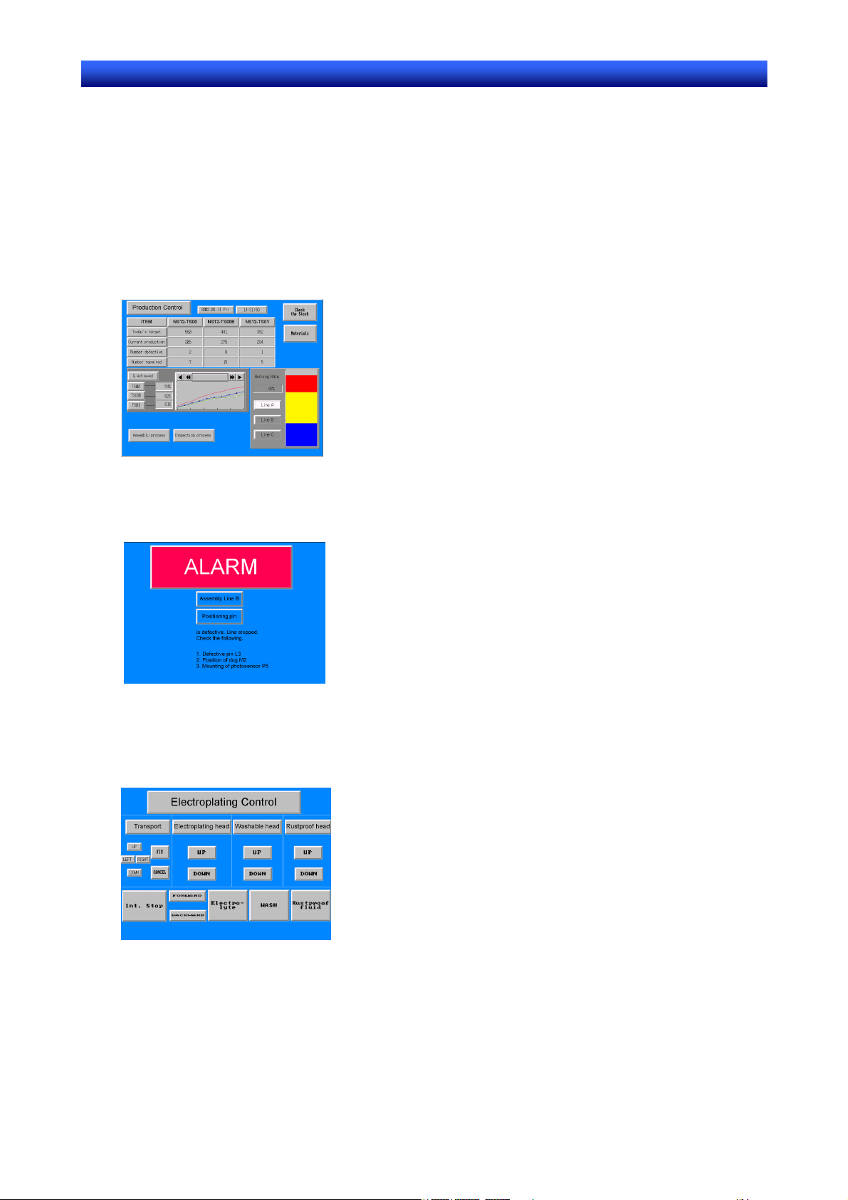
Monitoring Line Operating Status
The system and device operating status can be displayed in real time. Graphs can be used to improve
visual expressions to display data in an easy-to-understand format.
Instructions for FA Staff
PTs can be used to notify operators if there is a system or device error and provides information on
appropriate countermeasures.
Replacing Control Panel Switches
NS-series PTs have a touch panel. Buttons and other functional objects on the displayed screen can be
operated by touch.
1-1
Section 1 Overview 1-1 NS-series PT Operation
NS Series Programming Manual
1-1-2 NS-series PT Operation
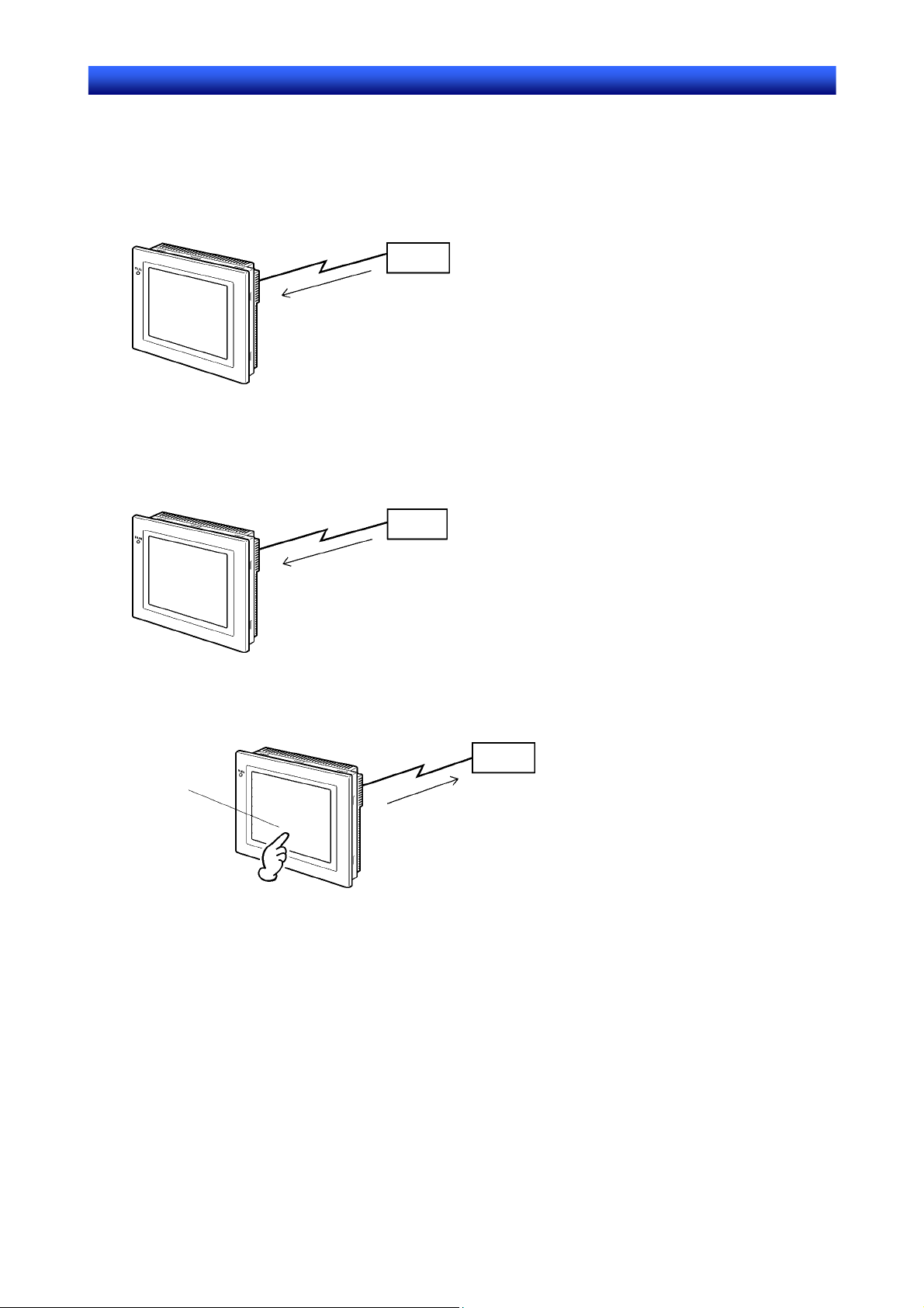
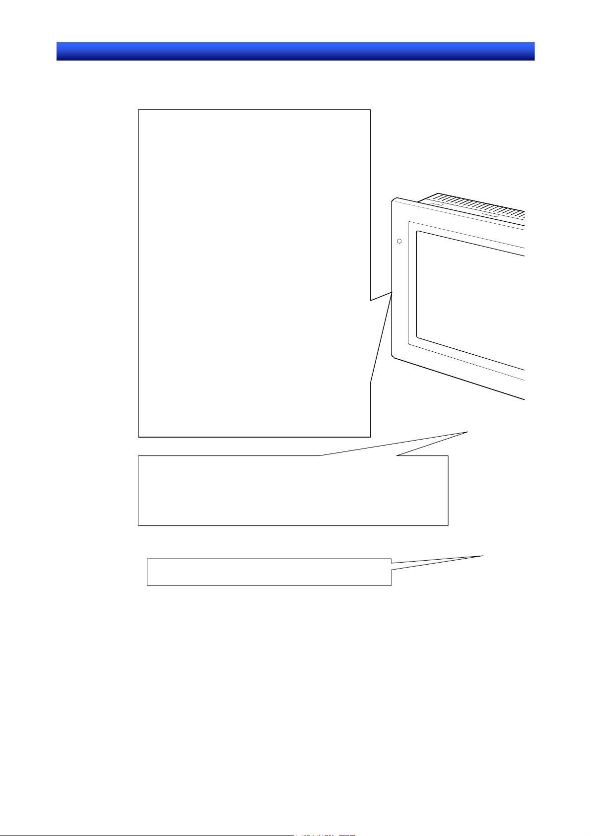
Displaying Screens
The data to be displayed on the screens (screen data) is created using the CX-Designer on a personal
computer and the data is stored in the PT. The required screen can be displayed by a command from the
host or by operating the touch switches.
Host
The required screens can be
displayed by using commands
from the host or touch switch
operations.
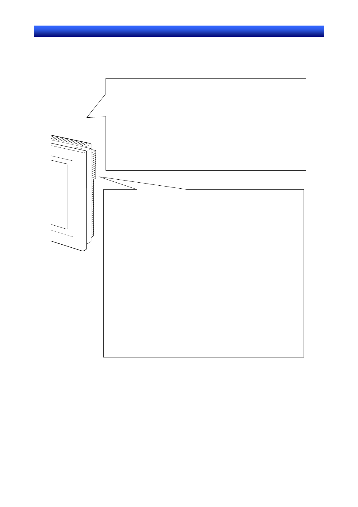
Reading Data from the Host
NS-series PTs connect to the host using NT Links, Ethernet (for NS15-TX01@-V2, NS12-TS01(B)-V1/
-V2, NS10-TV01(B)-V1/-V2, NS8-TV@1(B)-V1/-V2, NS5-SQ@1(B)-V1, NS5-SQ@1(B)-V2,
NS5-TQ@1(B)-V2, or NS5-MQ@1(B)-V2), or Controller Link (when Controller Link Interface Unit is installed) communications to automatically read required data from the host.
Host
NT Links, Ethernet, Controller Link
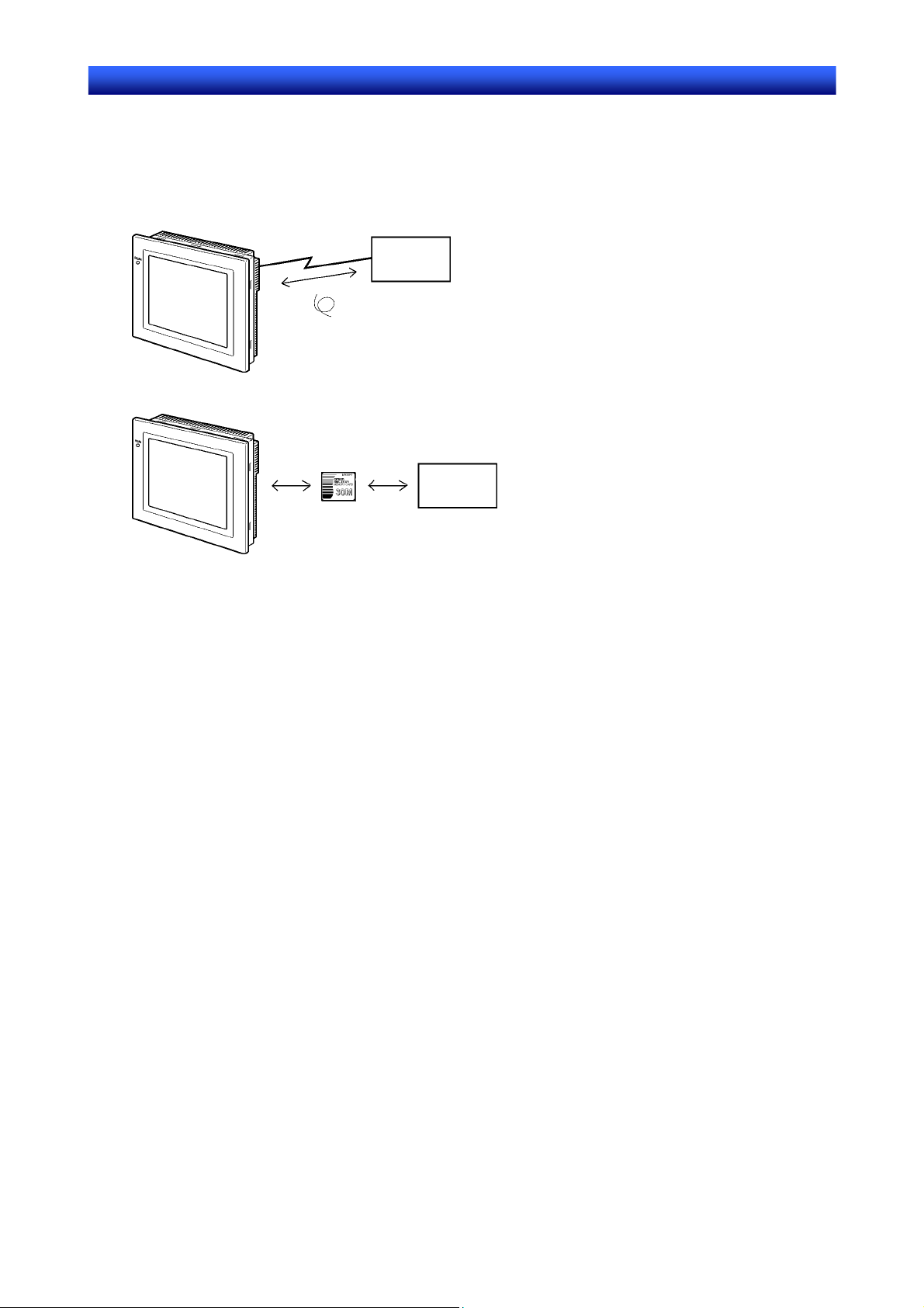
Sending Data to the Host
Data entered on the touch panel, (button ON/OFF status, numerals, and character strings) can be sent
to the host.
Host
Touch panel
ON/OFF information, numeric
data, etc.
1-2
Section 1 Overview 1-1 NS-series PT Operation
NS Series Programming Manual
Screen Data
The screen data displayed on PTs is created using CX-Designer on a personal computer. Screen data is
transferred to the PT by connecting the PT and the personal computer using an RS-232C cable, a USB
cable, or Ethernet (NS15-TX01@-V2, NS12-TS01(B)-V1/-V2, NS10-TV01(B)-V1/-V2,
NS8-TV@1(B)-V1/-V2, NS5-SQ01(B)-V1, NS5-SQ@1(B)-V2, NS5-TQ@1(B)-V2, or S5-MQ@1(B)-V2).
RS-232C, USB,
Ethernet
Screen data
Screen data can also be transferred using Memory Cards.
Create screen data.
Computer
(CX-Designer)
Connect the computer to the PT only when
transferring screen data to or from the CXDesigner.
Memory Card
Computer
(CX-Designer)
1-3

Section 1 Overview 1-2 NS-series PT Functions
NS Series Programming Manual
1-2 NS-series PT Functions
This section describes the features and main functions of the NS-series PTs.
1-2-1 NS-series PT Functions
Slim Body
1. Greater sophistication and reduced body thickness (panel depth 40 mm max.). (See note.)
2. Communications cable connectors housed inside Unit to eliminate protruding connectors.
Note: When mounted to a panel of the recommended thickness (1.6 to 4.8 mm).
Structure Suitable for FA Environments
1. Uses backlight with twice the life of previous OMRON PTs. (Return the PT to your nearest OMRON
service center for replacement (at user expense).
2. IP65F (see note) or NEMA4 equivalent watertight construction.
Note: May not be applicable in environments with long-term exposure to oil.
Two standard-feature Ports for Serial Communications, Ports A and B, Enabling
Connection to Both CX-Designer and the Host
1. Communications with the host via the other port are possible while still connected to CX-Designer.
2. Bar code data can be read from a bar code reader via the other port while communicating with the
host.
Ethernet Interface
Ethernet communications with the host are possible for the NS15-TX01@-V2, NS12-TS01(B)-V1/-V2,
NS10-TV01(B)-V1/-V2, NS8-TV@1(B)-V1/-V2, NS5-SQ01(B)-V1, NS5-SQ@1(B)-V2, NS5-TQ@1(B)-V2,
or NS5-MQ@1(B)-V2.
Ethernet/IP communications with the host are also possible with for the NS15-TX01@-V2,
NS12-TS01(B)-V2, NS10-TV01(B)-V2, NS8-TV01(B)-V2, NS5-SQ11(B)-V2, NS5-TQ11(B)-V2, and
NS5-MQ11(B)-V2.
The CPU Units available with tag message communications through Ethernet/IP and the corresponding
project versions are as follows:
Version 8.0 or higher: CJ2H-CPU@@-EIP, CJ2M-CPU3@
Version 8.5 or higher: NJ501-@@@@
Version 8.6 or higher: NJ101-@@@@, NJ301-@@@@
Version 8.9 or higher: NX701-@@@@
Version 8.93 or higher: NX1P2-@@@@
Version 8.96 or higher: NX102-@@@@
Controller Link Interface Unit
Installing a Controller Link Interface Unit enables using a Controller Link Network to send and receive
large data packets flexibly and easily among OMRON PLCs and IBM PC/AT or compatible computers.
Note: The Controller Link Interface Unit is supported by the NS15, NS12, and NS10 only.
Display Video Images with a Video Input Unit
Installing a Video Input Unit enables displaying images from a video camera or Vision Sensor.
1-4
Section 1 Overview 1-2 NS-series PT Functions
NS Series Programming Manual
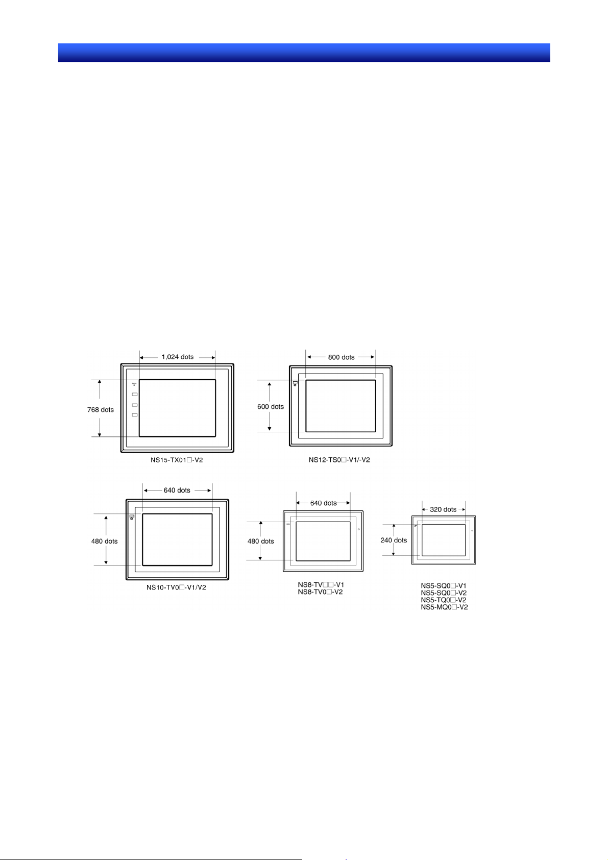
High Resolution and Large Display for a Wider Range of Display Possibilities
Display possibilities have been greatly increased with a larger display and higher resolution.
The NS15-TX01@-V2 uses an 1024-dot horizontal × 768-dot vertical, 256-color, 15.0-inch, bright TFT
LCD.
The NS12-TS0@-V1/-V2 uses an 800-dot horizontal × 600-dot vertical, 256-color, 12.1-inch, bright TFT
LCD.
The NS10-TV0@-V1/-V2 uses a 640-dot horizontal × 480-dot vertical, 256-color, 10.4-inch, bright TFT
LCD.
The NS8-TV@@-V1 uses a 640-dot horizontal × 480-dot vertical, 256-color, 8.0-inch bright TFT LCD.
The NS8-TV0@-V2 uses a 640-dot horizontal × 480-dot vertical, 256-color, 8.4-inch bright TFT LCD.
The NS5-SQ0@-V1/V2 uses a 320-dot horizontal × 240-dot vertical, 256-color, 5.7-inch STN LCD.
The NS5-SQ1@-V2 uses a 320-dot horizontal × 240-dot vertical, 256-color, 5.7-inch bright TFT LCD.
(Lot number 2110 or earlier: STN LCD.)
The NS5-TQ@@-V2 uses a 320-dot horizontal × 240-dot vertical, 256-color, 5.7-inch bright TFT LCD.
The NS5-MQ@@-V2 uses a 320-dot horizontal × 240-dot vertical, 16-grayscale monochrome, 5.7-inch
bright STN LCD.
For BMP or JPEG images, 32,000-color displays (4,096 colors for the NS5-SQ0@, 16 grayscales for the
NS5-MQ) are supported.
NS5-SQ1@-V2
NS5-TQ1@-V2
NS5-MQ1@-V2
More Precise Touch Switches
The NS12-TS0@-V1, NS10-TV0@-V1, NS5-SQ0@-V1, and NS5-SQ/TQ/MQ-V2 touch switches have
16-dot × 16-dot per element resolution and the NS8-TV@@-V1 touch switches have 20-dot × 20-dot per
element resolution.
The NS15-TX01@-V2 uses an analog touch panel.
Fast System Program and Screen Data Replacement Using Memory Cards
1. Screen data can be written on site simply by mounting an HMC-EF*** Memory Card on the PT.
1-5

Section 1 Overview 1-2 NS-series PT Functions
NS Series Programming Manual
2. System programs can also be stored on Memory Cards with NS-series PTs.
3. Operation log data that contains alarm history data, data log data, error log data, functional object
operations, screen display history, and macro execution history can be stored on Memory Cards.
Data is saved in CSV files, which are easy to use on a personal computer.
Screen Data Confirmation Function
Screens can be checked even if CX-Designer is not connected, by using the System Menu on the PT.
Large Increase in Object Capacity
The number of objects that can be registered to screens has been increased dramatically. This allows
screens with better display to be created. Refer to Display Specifications in Appendix 1 Specifications
for details.
Character Display in Windows Fonts
Fonts used in Windows can be used in fixed (text) displays.
Simple Upgrades
The system program can be replaced using a Memory Card.
Conforms to International Standards
The PT conforms to UL standards, CSA standards, and EC Directives.
Multiple Windows
Up to 3 pop-up windows can be displayed at the same time on a normal screen. Commands to switch
screens can also be given from the host.
Strong Processing Functions Using Macros
1. Various instructions are available, including arithmetic operations, bit operations, logic operations,
comparison operations, screen controls (open, close, etc.), and object movement.
2. Processing can be performed independently from the host or data from the host can be further
processed and the results can be displayed on the screen.
3. Host data processing can be transferred to macros to reduce the load on the host.
Multiple Label Registration
1. Up to 16 different languages or labels for production lines can be registered on one screen in the
NS-series PTs.
2. The displayed label can be switched during operation.
More than 1,000 Standard Parts
NS-series PTs provide not only touch switches and lamps, but also complicated parts such as toggle
switches and 7-segment displays. It is easy to create attractive screens simply by pasting on the
CX-Designer.
1-6

Section 1 Overview 1-2 NS-series PT Functions
NS Series Programming Manual
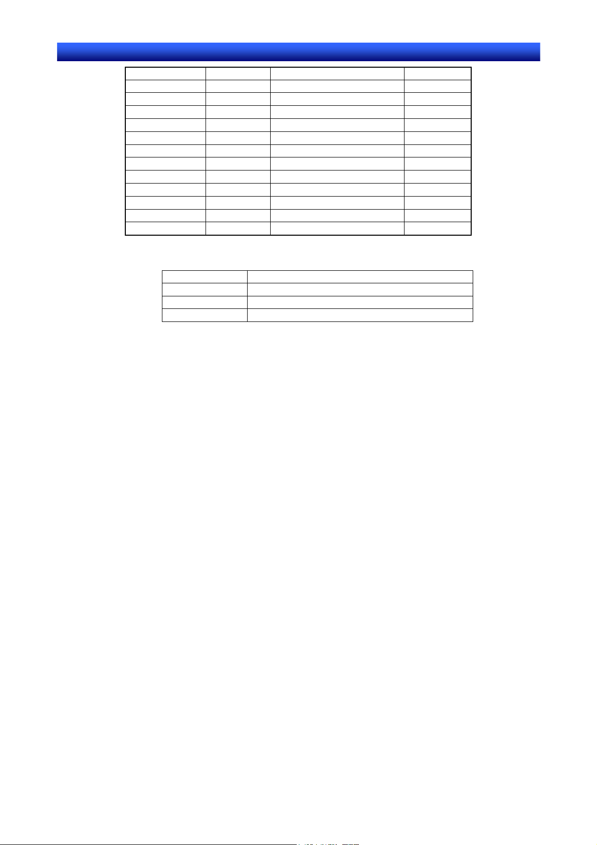
1-2-2 Differences between Models
The NS15, NS12, NS10, NS8, and NS5 have different screen sizes.
Also, some models support only serial communications while others also support communications via
the Ethernet.
Model Color Display panel Ethernet
NS15-TX01S-V2 Silver 15.0-inch bright TFT 10/100Base-T
NS15-TX01B-V2 Black 15.0-inch bright TFT 10/100Base-T
NS12-TS00-V1 Ivory 12.1-inch bright TFT Not available
NS12-TS00B-V1 Black 12.1-inch bright TFT Not available
NS12-TS01-V1 Ivory 12.1-inch bright TFT 10/100Base-T
NS12-TS01B-V1 Black 12.1-inch bright TFT 10/100Base-T
NS10-TV00-V1 Ivory 10.4-inch bright TFT Not available
NS10-TV00B-V1 Black 10.4-inch bright TFT Not available
NS10-TV01-V1 Ivory 10.4-inch bright TFT 10/100Base-T
NS10-TV01B-V1 Black 10.4-inch bright TFT 10/100Base-T
NS8-TV@0-V1
NS8-TV@0B-V1
NS8-TV@1-V1
NS8-TV@1B-V1
NS12-TS00-V2 Ivory 12.1-inch bright TFT Not available
NS12-TS00B-V2 Black 12.1-inch bright TFT Not available
NS12-TS01-V2 Ivory 12.1-inch bright TFT 10/100Base-T
NS12-TS01B-V2 Black 12.1-inch bright TFT 10/100Base-T
NS10-TV00-V2 Ivory 10.4-inch bright TFT Not available
NS10-TV00B-V2 Black 10.4-inch bright TFT Not available
NS10-TV01-V2 Ivory 10.4-inch bright TFT 10/100Base-T
NS10-TV01B-V2 Black 10.4-inch bright TFT 10/100Base-T
NS8-TV00-V2 Ivory 8.4-inch bright TFT Not available
NS8-TV00B-V2 Black 8.4-inch bright TFT Not available
NS8-TV01-V2 Ivory 8.4-inch bright TFT 10/100Base-T
NS8-TV01B-V2 Black 8.4-inch bright TFT 10/100Base-T
NS5-SQ00-V1 Ivory 5.7-inch STN Not available
NS5-SQ00B-V1 Black 5.7-inch STN Not available
NS5-SQ01-V1 Ivory 5.7-inch STN 10/100Base-T
NS5-SQ01B-V1 Black 5.7-inch STN 10/100Base-T
NS5-SQ00-V2 Ivory 5.7-inch STN Not available
NS5-SQ00B-V2 Black 5.7-inch STN Not available
NS5-SQ01-V2 Ivory 5.7-inch STN 10/100Base-T
NS5-SQ01B-V2 Black 5.7-inch STN 10/100Base-T
NS5-SQ10-V2
(See note.)
NS5-SQ10B-V2
(See note.)
NS5-SQ11-V2
(See note.)
NS5-SQ11B-V2
(See note.)
NS5-TQ00-V2 Ivory 5.7-inch bright TFT Not available
NS5-TQ00B-V2 Black 5.7-inch bright TFT Not available
NS5-TQ01-V2 Ivory 5.7-inch bright TFT 10/100Base-T
NS5-TQ01B-V2 Black 5.7-inch bright TFT 10/100Base-T
Ivory 8.0-inch bright TFT Not available
Black 8.0-inch bright TFT Not available
Ivory 8.0-inch bright TFT 10/100Base-T
Black 8.0-inch bright TFT 10/100Base-T
Ivory 5.7-inch TFT Not available
Black 5.7-inch TFT Not available
Ivory 5.7-inch TFT 10/100Base-T
Black 5.7-inch TFT 10/100Base-T
1-7
Section 1 Overview 1-2 NS-series PT Functions
NS Series Programming Manual
Model Color Display panel Ethernet
NS5-TQ10-V2 Ivory 5.7-inch bright TFT Not available
NS5-TQ10B-V2 Black 5.7-inch bright TFT Not available
NS5-TQ11-V2 Ivory 5.7-inch bright TFT 10/100Base-T
NS5-TQ11B-V2 Black 5.7-inch bright TFT 10/100Base-T
NS5-MQ00-V2 Ivory 5.7-inch monochrome STN Not available
NS5-MQ00B-V2 Black 5.7-inch monochrome STN Not available
NS5-MQ01-V2 Ivory 5.7-inch monochrome STN 10/100Base-T
NS5-MQ01B-V2 Black 5.7-inch monochrome STN 10/100Base-T
NS5-MQ10-V2 Ivory 5.7-inch monochrome STN Not available
NS5-MQ10B-V2 Black 5.7-inch monochrome STN Not available
NS5-MQ11-V2 Ivory 5.7-inch monochrome STN 10/100Base-T
NS5-MQ11B-V2 Black 5.7-inch monochrome STN 10/100Base-T
Note: The specifications of NS5-SQ1@-V2 PTs with lot number 2110 (manufactured January 21, 2010)or
earlier are given below.
Item Specification
Display panel Color STN LCD
Display colors 256 colors (4,096 colors for BMP/JPEG images)
View angle Left: 50°, Right: 50°, Top: 45°, Bottom: 50°
1-8
Section 1 Overview 1-2 NS-series PT Functions
NS Series Programming Manual
1-2-3 Main NS-series Functions
The NS-series PTs have the following main functions.
Display Functions
Screen Displays
Large, high - resolution screen with many graphic functions.
1024 x 768 - dot (horizontal x vertical), 256 - color, 15.0-in, bright TFT LCD
NS15-TX01@-V2
800 x 600 - dot (horizontal x vertical), 256 - color, 12.1-in, bright TFT LCD
NS10-TV0@-V1/-V2
640 x 480 - dot (horizontal x vertical), 256 - color, 10.4-in, bright TFT LCD
NS8-TV@@-V1
640 x 480 - dot (horizontal x vertical), 256 - color, 8.0-in, bright TFT LCD
NS8-TV0@-V2
640 x 480 - dot (horizontal x vertical), 256 - color, 8.4-in, bright TFT LCD
NS5-SQ0@-V1/-V2
32 0 x 24 0 - dot (horizontal x vertical), 256 - color, 5.7-in, STN LCD
NS5-SQ1@-V2 (See note.)
320 x 240 - dot (horizontal x vertical), 256 - color, 5.7-in, TFT LCD
NS5-TQ@@-V2
32 0 x 24 0 - dot (horizontal x vertical), 256 - color, 5.7-in, bright TFT LCD
NS5-MQ@@-V2
320 x 240 - dot (horizontal x vertical), 5.7-in, 16-grayscale monochrome
STN LCD
Characters
Display characters at various sizes. Characters can be flashed or
character colors can be changed.
Fixed Objects
Lines, poly lines, rectangles, polygons, circles, oval, arcs, and sectors
can be displayed. Objects can be filled in various colors and flashed.
Internal Memory Data
The contents of registers in internal memory ($B, $W, $HB, $HW, $SB,
and $SW) can be displayed.
Graphs
Bar graphs, analog meters, broken - line graphs, and trend (data
logging) graphs are supported.
Lamps
Lamps controlled by the host can be lit or flashed. Different graphics
can be used for lit and not lit status.
Alarms/Events
Host bit status can be used to automatically display messages and
related information (e.g., time stamps).
Alarms and events can be displayed one line at a time, in lists,
or in histories.
RUN
Note: Lot number 2110 or earlier use an STN LCD.
Communications Functions: Host Communications
Any of five communications methods can be used: 1:1 NT Links, 1:N NT
Links (standard or high speed), Ethernet, Ethernet/IP (Ethernet: NS15-TX01@-V2, NS12-TS01(B)-
V1/-V2, NS10- TV01(B)-V1/-V2, NS8-TV@1(B)-V1/-V2, NS5- SQ01(B)-V1,
NS5-SQ@1(B)-V2, NS5-TQ@1-V2, and NS5-MQ@1-V2), or Controller Link. Host data can be
read and displayed, and data can be input and sent to the host, for buttons, numeral display and
input objects, and character display and input objects.
Output Functions: Buzzer
The buzzer in the PT can be controlled
1-9
Section 1 Overview 1-2 NS-series PT Functions
NS Series Programming Manual
Input Functions
Inputting via Touch Switches
Buttons can be displayed easy input by touching the screen. Input functions include sending data to the host and
switching the display screen.
Pop- up Windows
Windows that overlap the current screen can be opened, closed, and moved. Various objects can be registered
for pop-up windows, and up to three pop- up windows can be displayed at the same time. Accessing the required
windows when needed enables more effective use of screens.
Numeral/Character String Input
Touch switches can be used to input numerals and character strings. The input data can be sent to the host, and
inputs can also be prohibited using controls from the host.
Bar Code Reader Inputs
Data read from bar code readers can be input to character string display and input objects.
Control Flags
Allocating host addresses to control bits enables controlling display of functional objects and enabling or disabling
input functions from the host.
System Functions
System Menu
System setting and maintenance are performed from the system menu displayed on the screen.
Creating Screen Data
The CX-Designer running on a personal computer is used to create screen data and record it in memory built into the
PT. Screen data can also be saved on Memory Cards in the PT.
Screen Saver
A screen saver increases the life of the backlight.
Built-in Clock
The built- in clock enables displaying dates and times.
Device Monitor Function
When connected to a PLC via a 1:1 NT Link, 1:N NT Link, or Ethernet, the PLC’s operating mode can be changed,
words in the PLC can be read or written, error information can be written, etc.
Data Transfers
Screen data and system programs can be transferred by the Transfer Data function on the CX-Designer or by using
Memory Cards. Data can also be transferred to the PT through a PLC and ladder program data, for example, can be
transferred through a PT to a PLC.
Operation Logging and Alarm/Event History
A history can be kept of screen switches, functional object operation, and macro execution. The times and frequency
that specific addresses turn ON can also be kept in a history.
Data Logging for Trend Graphs and Background Execution
The contents of addresses displayed for trend graphs can be logged, even while the graph is not being displayed
(background execution).
Macros
Calculations data can be set as screen data to perform calculations at specific times during PT operation.
Calculations include arithmetic, bit operations, logic operations, and comparisons. Various commands are also
provided, e.g., to move objects or pop-up windows, manipulate character strings, etc.
Starting External Applications
Ladder monitor or other applications can be started from the system menu.
Printing
Screens can be printed out on a printer connected with an USB cable NS15, NS12, NS10, NS8, or NS5-@@1@-V2 only.
Programming Console Function
The PT can perform Programming Console functions by placing a Memory Card containing a program into the PT.
NS Switch Box
The comments of a specified PLC address can be displayed and data at the address can be monitored or changed.
1-10
Section 1 Overview 1-2 NS-series PT Functions
NS Series Programming Manual
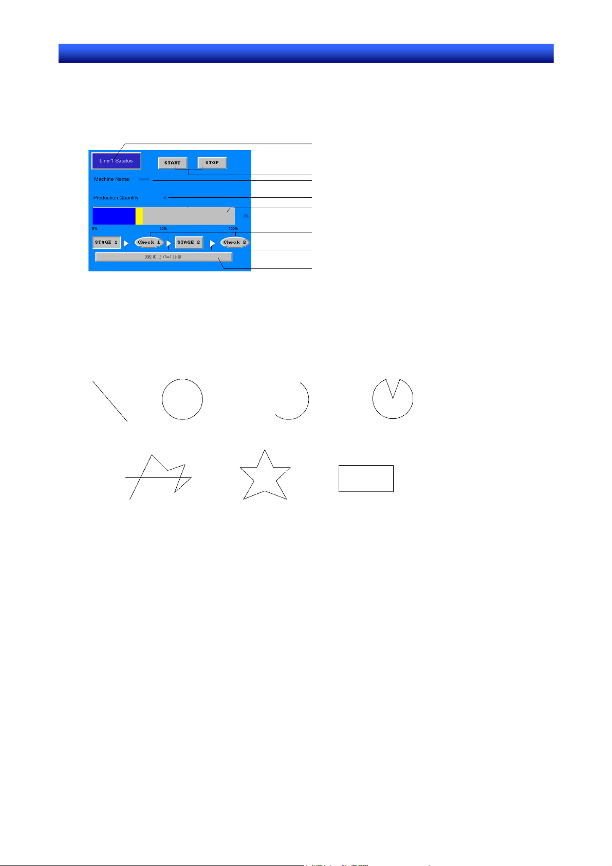
1-2-4 NS-series Displays
A variety of elements can be displayed on one screen, including character strings, numerals, graphs,
lamps, and buttons. The screen data displayed on NS-series PTs is created using CX-Designer.
Fixed Objects
A fixed object is merely graphic data displayed on the screen. Unlike functional objects, fixed objects
cannot exchange data with the host, execute operations, or change display attributes (except for flickering). There are seven types of fixed objects: Lines, circles/ovals, arcs, sectors, polylines, polygons,
and rectangles.
Line
Circle or Oval
Arc Sector
Characters (text)
ON/OFF buttons
Characters (string display and input)
Numerals (numeral display and input)
Graphs (level meter)
Lamps (bit lamps)
Fixed objects
Alarm objects
(Alarm/event display)
P o lyline
Polygon Rectangle
Buttons
Button can be registered to the screens as required. There are three types of buttons: ON/OFF buttons,
word buttons, and command buttons. The following functions can be executed by touching the buttons
on the screen.
• Turn bits ON or OFF (ON/OFF buttons).
• Write numerals to words (word buttons).
• Switch the displayed screen (command buttons).
• Transfer numeral or character string data (command buttons).
• Open, close, or move pop-up screens (command buttons).
• Display the System Menu (command buttons).
• Stop the buzzer (command buttons).
Buttons can be lit depending on the status of the allocated address.
Also, inputs from the host can be controlled (enabled or disabled) by allocating the address of a control
flag.
There are three display shapes for buttons: Rectangle, select shape (ON/OFF buttons and word buttons), and circle (for ON/OFF buttons only). When the select shape option is used, the display shape is
specified for the ON and OFF status of the allocated address.
There are two types of button labels: Fixed string display and ON/OFF switch display (for ON/OFF
buttons only). In addition, the label can be displayed on multiple lines.
1-11
Section 1 Overview 1-2 NS-series PT Functions
NS Series Programming Manual
Lamps
There are two types of functional objects, bit lamps and word lamps, that change the display status
depending on the status of the allocated address.
The color and shape of the lamps can be changed depending on the ON/OFF status of bits for bit lamps
or the contents of words for word lamps.
Allocated address
0, 1, 0, 1……
OFF, ON, OFF, ON……
Color 1, Color 2, Color 3, Color 4……
Allocated address
0, 1, 2, 3, 4, 5……
Bit lamp Word lamp
Fixed character strings can be displayed as lamp labels. In addition, multiple lines can be displayed.
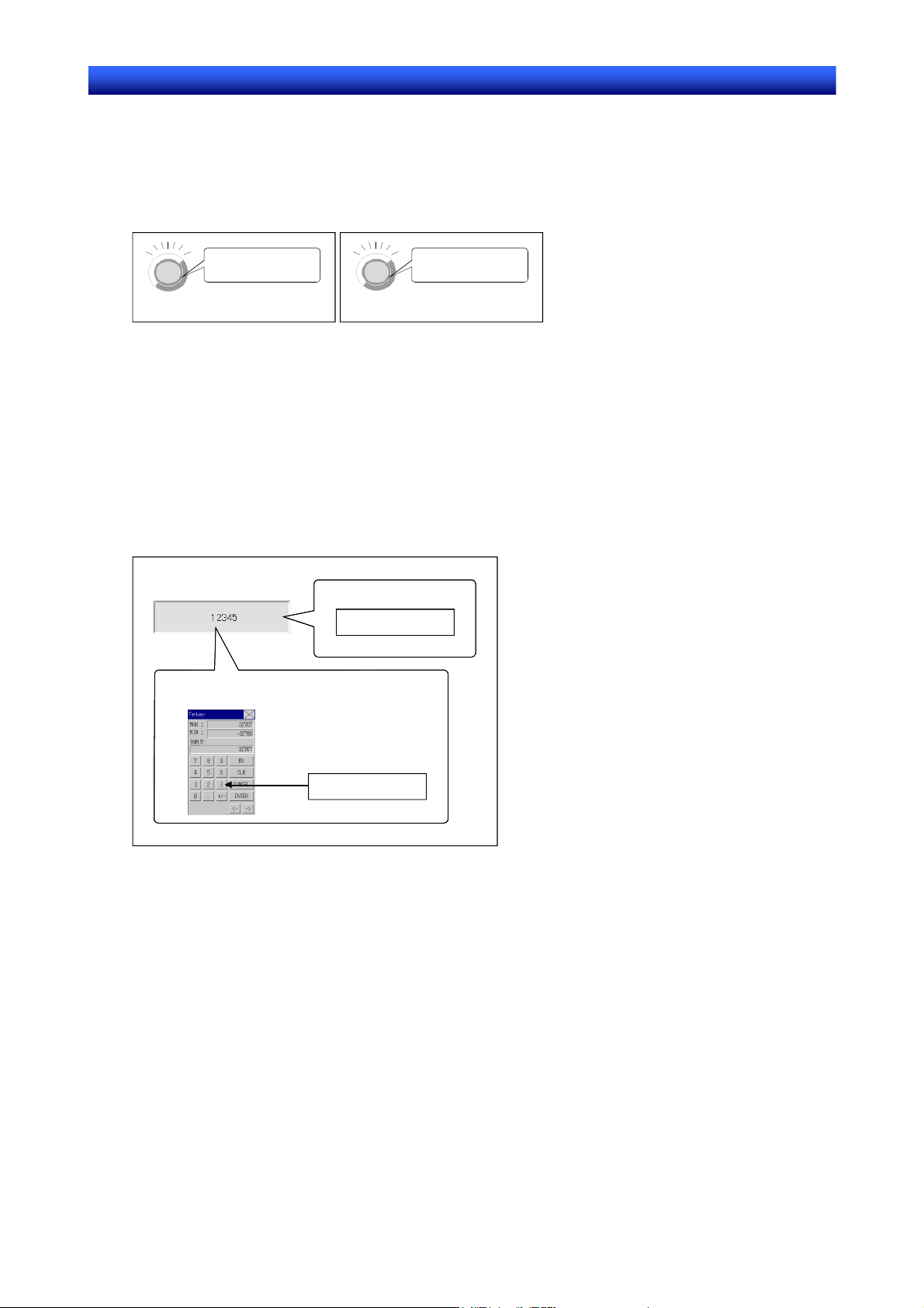
Numeral Display and Input
Numerals stored at the allocated address can be displayed and data can be input to the allocated address. Four different data formats can be displayed as required, including decimal and hexadecimal,
and data can be stored as required in any of eleven data formats, including signed integers and BCD.
Host values can be converted and displayed at a specified scale or displayed with units, such as mm or
g.
Also, inputs from the host can be controlled (enabled or disabled) by assigning the address of a control
flag.
Allocated address
12345
Keypad input
12345
1-12
Section 1 Overview 1-2 NS-series PT Functions
NS Series Programming Manual
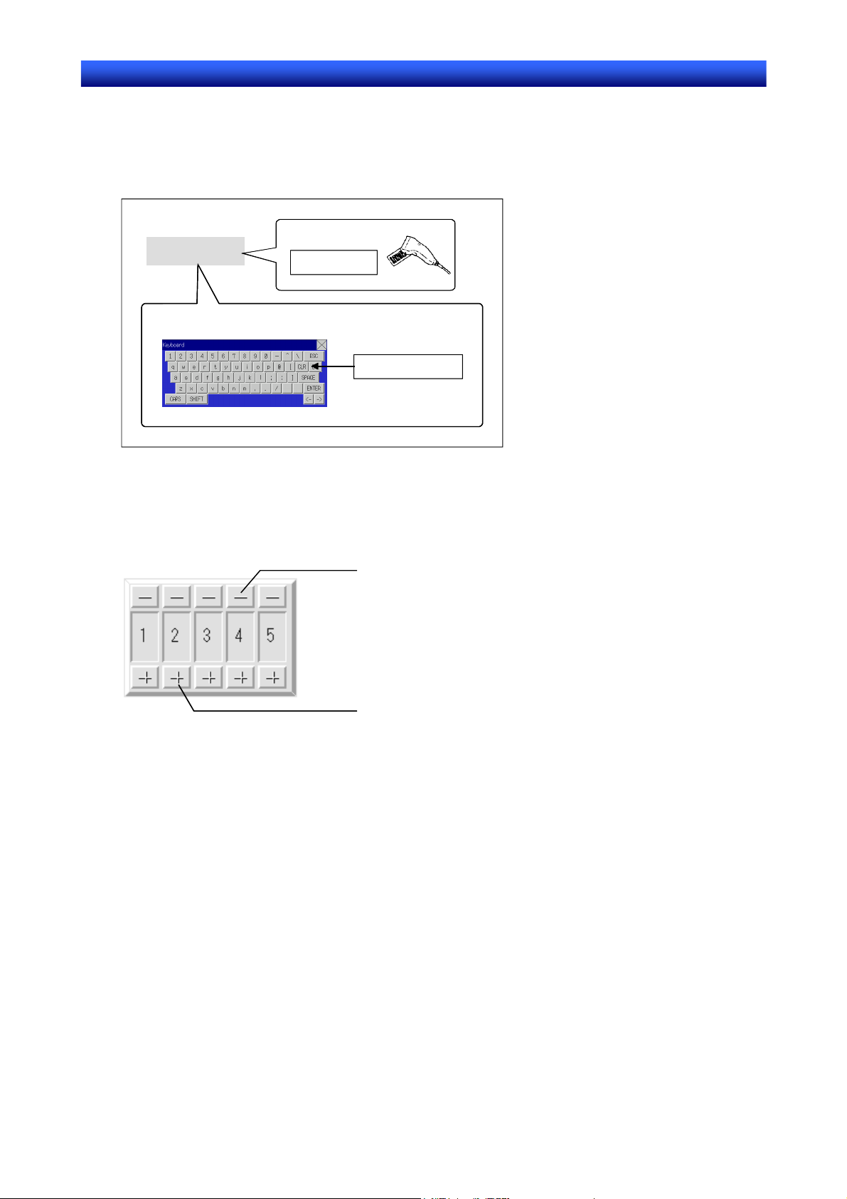
String Display and Input
Character string data stored at allocated addresses can be displayed and can be input to the address.
Bar code data can be read using a bar code reader.
Also, inputs from the host can be controlled (enabled or disabled) by allocating the address of a control
flag.
Barcode input
Character string
Virtual keyboard input
Character string
Character string
Thumbwheel Switches
The numerical contents of the allocated address can be input by incrementing or decrementing the
numeral using the + and – buttons for each digit.
Also, inputs from the host can be controlled (enabled or disabled) by allocating the address of a control
flag.
Decrement
Increment
1-13
Section 1 Overview 1-2 NS-series PT Functions
NS Series Programming Manual
List Selections
Allocated addresses or character string data stored in text files can be displayed in a list and specific
character strings can be specified from the list.
Also, inputs from the host can be controlled (enabled or disabled) by allocating the allocated address of
a control flag.
Item 1
Item 2
Item 3
Item 4
Item 5
Item 6
Item 7
Text files
Item 1
Item 2
Item 3
Item 4
Allocated address
Item 1
Item 2
Item 3
Item 4
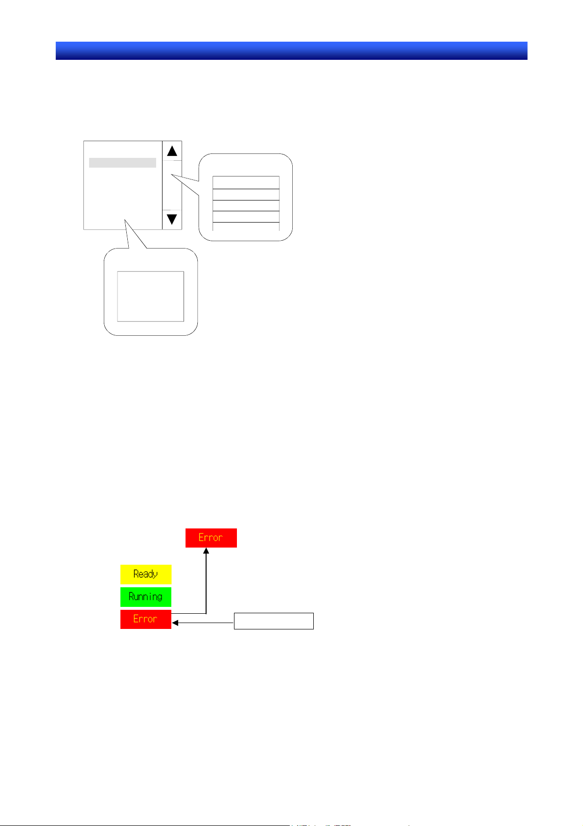
Text
Preset character strings can be displayed.
Display characters can also be changed.
The following three methods are available for changing displayed characters.
• Indirect Specification From a Text File
A list of character strings to be displayed can be stored in a text file and any character string in the text
file can be specified for display.
• Indirect Specification From a Character String Table
Any character string can be specified for display from preset character strings in a character string
table.
• Message Indicator Function
Character strings and background colors to be displayed can be registered for each status number
and any registered status can be specified for display.
Status 1
Status 2
Status 3
Text object
Displays status 3.
Status switching
addresses
HOST1: 00001=2
Specifies status 3.
Bitmaps
Bitmaps are functional objects that display bitmap files or JPEG files. Complex pictures or photographic
images that cannot be drawn can be displayed on the screen. The display can also switch among different images depending on the contents of the specified address.
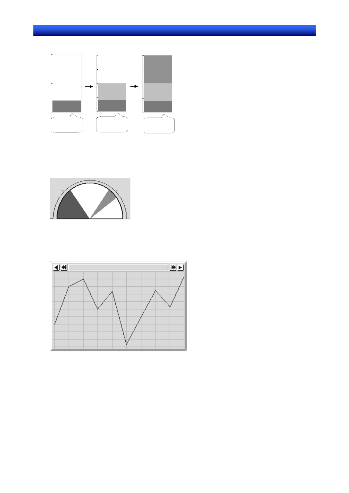
Level Meters
The current value of the allocated address can be displayed by coloring the specified range. The display
1-14
Section 1 Overview 1-2 NS-series PT Functions
NS Series Programming Manual
direction (up, down, left, or right), different color for each specified range, and whether or not scaling will
be used can be set.
100
50
20
0
Allocated address
contains 20.
Allocated address
contains 50.
Allocated address
contains 100.
Analog Meters
An analog meter displays the current value for the allocated address by coloring regions or by means of
a needle. The shape can be selected from a quarter circle, semi-circle, and full circle.
The display direction (up, down, left, or right), incremental direction for the meter (clockwise or anti-clockwise), and whether or not scaling will be used can be set.
Broken-line Graphs
Broken-line graphs display the present values for multiple consecutive allocated addresses on one
graph.
Up to 256 line graphs can be displayed in one broken-line graph display region.
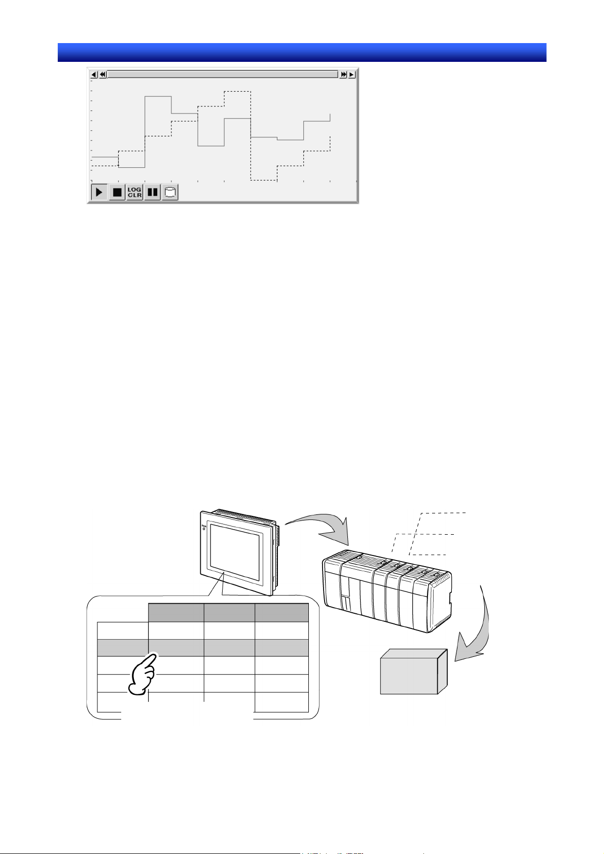
Data Log Graphs
The data log function saves changes over time in the contents of the allocated address. The saved data
can be displayed for each data logging group.
Data can be read (sampled) even if the data log graph is not displayed.
1-15
Section 1 Overview 1-2 NS-series PT Functions
NS Series Programming Manual
Alarms and Events
The alarm/event function reports alarms based on changes in bit status. There are two functional objects: Alarm/event displays and alarm/event summary and history.
Alarm/event display objects display a pre-registered message and the date and time of the alarm or
event when the monitored bit turns ON.
Either one message or multiple messages (using the flowing string function) can be displayed.
The alarm/event summary and history functional object displays a list of messages. The display order
can be switched between displaying in order of occurrence, order of frequency, and by alarm level. Also,
the history and data to be displayed when an alarm is generated can be selected.
System Clock
The system clock displays the current date and time. The date and time can also be changed.
Data Blocks
Data blocks (recipes) enable reading/writing values and character strings from/to memory areas, such
as those in a PLC. Data blocks can be used to easily change the setup of the system. Create the data in
a CSV file and store it in the PT beforehand. This data can be changed while operating the PT.
Example: Setting width (numeric value), height (numeric value), and color (character string) in the PLC.
(Refer to the figure shown below.)
Set width: 150, height: 54, and color: blue for product B. Just select product B to set these three items in
the PLC. If product A is selected a width for 100, a height of 52, and a color of red are set in the PLC.
Data Block
Product A
Product B
Product C
Product D
Product E
Width Height Color
100
150
200
300
Product B selected to set
52 Red
54
56
62
Blue
Yellow
Red
Blue
Product B processing conditions
To machines
Product B
1-16

Section 1 Overview 1-2 NS-series PT Functions
NS Series Programming Manual
Using data blocks, users do not need to save data in the PLC beforehand, so that the memory of the
PLC can be saved and the ladder program can be reduced. Data blocks also have the following features.
• Data in CSV format can be edited and managed on a computer.
• Data can be edited on the PT.
• Data can be written to a Memory Card.
• Data from read from a Memory Card.
• Process values and character strings can be handled.
• Maximum number of rows: 1,000. Maximum number of columns: 500. Data blocks with both 1,000
rows and 500 columns, however, cannot be set.
Video Displays
Installing a Video Input Unit (NS-CA001) on the NS12, NS10, or NS8 enables displaying images output
from video devices, such as video cameras or Vision Sensors, to be displayed on the PT. Up to four
video devices can be connected to the PT. There are two input methods: NTSC and PAL.
Video Input Unit
4ch
3ch
2ch
1ch
Video cameras or
Vision Sensors
With an NS15,* NS12, NS10, or NS8 PT, an NS-CA002 RGB/Video Input Unit can be mounted to display receive an external video or RGB signal for display on the NS-series PT.
*: Video inputs cannot be used with the NS15 PT. Only analog RGB inputs can be used.
Consecutive Line Drawing
Polylines can be drawn by using the contents of communications addresses as coordinates of the vertex
points. These shapes differ from regular polylines because the shapes can be changed actively.
1-17

Section 1 Overview 1-2 NS-series PT Functions
p
g
NS Series Programming Manual
The communications address’ values
s
ecify each vertex’s X and Y coordinates.
Vertex 2 (5,0)
Vertex 1 (0,10)
Value of communications address 1: 0
Value of communications address 2: 10
Value of communications address 3: 5
Value of communications address 4: 0
Value of communications address 5: 20
Value of communications address 6: 10
Vertex 3 (20,10)
Coordinates of vertex 1
Coordinates of vertex 2
Coordinates of vertex 3
Vertices change as the values of the
communications addresses chan
(10,10)
Value of communications address 1: 0
Value of communications address 2: 0
Value of communications address 3: 10
Value of communications address 4: 10
Value of communications address 5: 20
Value of communications address 6: 0
e.
(20,0) (0, 0)
Multifunction Objects
Multifunction Objects are functional objects that can execute multiple functions in order with a one-touch
operation.
The set functions are executed one after the other when the Multifunction Object is pressed or the value
at a specified address changes. Up to 32 functions can be set for each execution condition.
The Multifunction Object function enables operations that were performed using a combination of
macros and multiple functional objects to be performed in one operation.
Executed in one operation.
1. Turns ON $B100.
↓
2. Sets DM100 to 10.
↓
3. Turns ON CIO0.0.
↓
4. Switches to screen 50.
* Safety functions can be set as an execution condition for when the Multifunction Object is pressed,
e.g., Double Press, ON Delay, OFF Delay, and Prohibit Simultaneous Press
Contents Display
Contents Display is a functional object that switches character string and image file display according to
its status. Character string displays and image files are indicated by the term “contents” and settings for
switching display is referred to as the settings for switching contents.
The character string and image combinations and the communications address for switching display for
each status (i.e., each contents number) are made in the settings for switching contents.
Contents display switches the displayed character string/images according to the specified communications address. The contents display can also be switched in connection with any alarms/events that
occur or are cleared.
Example Settings for Switching Contents
No.
0
1
String Image
Close the front
cover.
Replace the battery.
Contents Contents
Manual1.bmp
Manual2.bmp
1-18

Section 1 Overview 1-2 NS-series PT Functions
NS Series Programming Manual
Character
string
Manual1.bmp
Contents switching address value: 0
Displays the character
string and image registered
to contents number 0.
Contents switching address value: 1
Switches to display the
character string and image
registered to contents number
1.
1-19

Section 1 Overview 1-3 Communicating with the Host
NS Series Programming Manual
1-3 Communicating with the Host
1-3-1 Host Registration and Address
With NS-series PTs, data required for display can be accessed and the words and bits where the entered data will be stored can be allocated to any area in the PLC.
The allocated words and bits are read from and written to directly, the display status changed for the
objects on the PT screen, and the PT status controlled or reported.
Communications with multiple PLCs are also possible with NS-series PTs. Host names are registered
for the connected PLCs and any area in the PLC can be accessed by specifying the host name and
address. Connect to the host using one of the following methods.
NS-series PT PLC
DM Area I/O Area
Auxiliary Area
Timers/counters
• 1:1 NT Link
• 1:N NT Links (standard, high speed)
• Ethernet
• Controller Link (When Controller Link Interface Unit is installed.)
• Host Link
• Temperature Controller Connection
• Memory Link
• Connection with PLCs and other devices from other manufacturers.
• EtherNet/IP
Up to 48 registrations are possible for hosts.
Refer to the Host Connection Manual: Temp. Control, MemLink for details on Temperature Controller
connections and Memory Links. Refer to the Host Connection Manual: Multivendor Connection for
details on connecting to another company’s PLC.
1-3-2 Ethernet
Hosts connected on the Ethernet can communicate with devices that support FINS (Factory Interface
Network Service) messages. FINS is a standard OMRON communications service. NS-series PTs can
read and write data, word contents, and bit status from supported PLC Ethernet Units without having to
be concerned about protocols.
The following PLCs can be connected using Ethernet.
CS1G/CS1H-E(V1), CS1G/CS1H-H, CVM1/CV, CJ1G, CJ1G-H/ CJ1H-H, CJ1M, CP1H, CP1L, CP2E,
CJ2H, and CJ2M.
1-3-3 Controller Link
The Controller Link is an FA network that can send and receive large data packets among OMRON
PLCs and IBM PC/AT or compatible computers. The Controller Link supports data links that enable data
sharing and a message service that enables sending and receiving data when required.
The following PLCs can be connected using Controller Link: CS1G/CS1H-E(V1), CS1G/CS1H-H,
CVM1/CV, C200HX/HG/HE(-Z), and CVM1(-V2), CQM1, CJ1G, CJ1G-H/ CJ1H-H, CJ1M, CJ2H, and
CJ2M.
Note: The Controller Link Interface Unit is supported by the NS15, NS12, and NS10 only.
1-20

Section 1 Overview 1-3 Communicating with the Host
NS Series Programming Manual
1-3-4 NT Links
The NT Link protocol was specially designed to enable high-speed communications with OMRON
PLCs.
The following PLCs can be connected using NT Links.
CPM1A, CPM2A, CPM2C, CQM1, CQM1H, C200HS, C200HX/HG/HE-E/-ZE, CS1G/CS1H-E(V1),
CS1G/CS1H-H, CVM1/CV (V1 or later), CJ1G, CJ1G-H/ CJ1H-H, CJ1M, CP1H, CP1L, CP1E, CP2E,
CJ2H, and CJ2M
In addition to the 1:1 NT Links, where one PT serial port is connected to one PLC, NS-series PTs can
also use the 1:N NT Links, where up to eight PTs are connected to one PLC.
The following PLCs can be connected using a 1:N NT Links.
CQM1H, C200HX/HG/HE-E/-ZE, CS1G/CS1H-E(V1), CS1G/CS1H-H, CJ1G, CJ1G-H/ CJ1H-H, CJ1M,
CP1H, CP1L, CP1E, CP2E, CJ2H, and CJ2M.
NS-series PTs also support a high-speed 1:N NT Link that allows faster communications. The following
PLCs can be connected using a high-speed 1:N NT Links.
CS1G/CS1H (V1 or later), CS1G/CS1H-H, CJ1G, CJ1G-H/ CJ1H-H, CJ1M, CP1H, CP1L, CP1E, CP2E,
CJ2H, and CJ2M.
In later sections, the term “NT Link” will be used when describing the NT Link communications method in
general, “1:1 NT Link” will be used when describing the 1:1 NT Link connection method only, and “1:N
NT Link” will be used when describing the 1:N NT Link connection method only. Furthermore, differentiation will be made between standard and high-speed 1:N NT Links when required. If only “1:N NT Link”
is noted, the description will refer to both standard and high-speed 1:N NT Links.
NT Link Features
NT Links have the following features.
1. NT Links facilitate high-speed communications with PLCs. The high-speed 1:N NT Link, which
enables even faster communications, is also supported.
2. Data can be written to PLC memory areas in bit units. This allows other bits in the word to which a
touch switch has been allocated to be used for another applications, such as lamp allocations.
However, data is written in word units only in the DM and EM Areas, so other bits in the word to
which touch switches are allocated cannot be used for other applications in these memory areas.
3. NS-series PTs can be connected without switching PLC operating modes.
4. Up to eight PTs can be connected to one PLC port when 1:N NT Links are used and all ports can be
used simultaneously. Up to eight ports can be used simultaneously for high-speed 1:N NT Links also.
Normal 1:N NT Links and high-speed 1:N NT Links cannot, however, both be used on the same PLC
port.
5. If a Communications Board is mounted in the CPU Unit option slot on a C200HX/HG/HE-E/-ZE PLC,
up to three standard 1:N NT Link systems (up to 24 PTs) can be connected. Only standard 1:N NT
Link connections can be made. Refer to the C200HX/HG/HE Communications Boards Operation
Manual (W304-E1-@) for information on Communications Boards.
6. If a Serial Communications Board is mounted in the CPU Unit Inner Board slot on CQM1H PLCs, up
to two standard 1:N NT Link systems (up to 16 PTs) can be connected. Only standard 1:N NT Link
connections can be made. Refer to CQM1H Serial Communications Board Operation Manual
(W365-E1-@) for information on Serial Communications Boards.
7. If a Serial Communications Board is mounted to the CPU Unit Inner Board slot or a Serial Communications Unit is mounted to the Backplane of a CS1G/H or CS1G/H PLC, multiple standard or
high-speed 1:N NT Link systems can be connected. Refer to CS/CJ Series Serial Communications
Boards and Unit Operation Manual (W336-E1-@) for information on Serial Communications Boards
and Serial Communications Units.
8. If the PLC supports the device monitor function, the PLC operating mode can be switched from the
PT and the present values of words can be displayed or changed.
1-21

Section 1 Overview 1-3 Communicating with the Host
NS Series Programming Manual
1-3-5 Host Link
The Host Link method uses a 1:1 connection between the host and a PT to read and display word and bit
data from the host. Many PLC models can be connected using Host Link.
The following PLCs can be connected to NS-series PTs using Host Link. The PLCs are connected via
their built-in serial port or a Host Link Unit supported by the PLC.
C Series
C200HS, C200HX/HG/HE(-Z), CQM1, CQM1H, CPM2A/CPM2C, CPM1/CPM1A, C500, C1000H, and
C2000H
CV Series
CV500, CV1000, CV2000, and CVM1
CS/CJ Series
CS1G/CS1H, CS1G-H/CS1H-H, CJ1G, CJ1G-H/CJ1H-H, CJ1M, CP1H, CP1L, CJ2H, and CJ2M
Refer to Host Connection Manual: Host Link for details on Host Link communications settings.
1-3-6 EtherNet/IP
EtherNet/IP is an industrial multivendor network protocol that uses Ethernet. The specification is an
open standard managed by the ODVA (Open DeviceNet Vendors Association) as is DeviceNet, and it is
used for a variety of industrial devices. With NS-series PTs, communications can be performed with
CS/CJ-series EtherNet/IP Units and CJ2H-CPU@@-EIP, CJ2M-CPU3@, NJ@01-@@@@,
NX@0@-@@@@, or NX1P2-@@@@ Units with a built-in EtherNet/IP port.
Also, it is possible to perform tag message communications when using a CPU Unit with a built-in
EtherNet/IP port. These CPU Units contain a tag name server, so if tag names and an address table are
stored in advance in the CPU Unit, it is possible to perform access from the NS-series PT using only the
tag names.
1-3-7 PT Memory
PT memory is made up of internal memory and system memory.
Internal Memory
The internal memory in the PT can be read and written by the user. Internal memory can be allocated as
required for settings, such as the addresses for functional objects.
The internal memory is divided into four sections.
Memory Contents
$B Bit Memory
Bit memory is used for I/O flags and signal information.
Up to 32 Kbits (32,768 bits).
$W Word Memory
Word memory is used to store numeral and character string data.
Each word contains 16 bits, but consecutive words can be used as required for
character strings and 32-bit data.
Up to 32 Kwords (32,768 words).
$HB Internal Holding Bit Memory
Internal Holding Bit Memory is used for I/O flags and signal information.
Up to 8 Kbits (8,192 bits) can be used. Values are held even when the power supply to
the PT is turned OFF.
$HW Internal Holding Word Memory
Internal Holding Word Memory is used to store numeral and character string data.
Each word contains 16 bits, and consecutive words can be used as required for
character strings and 32-bit data.
Up to 8 words (8,192 words) can be used. Values are held even when the power
supply to the PT is turned OFF.
1-22

Section 1 Overview 1-3 Communicating with the Host
NS Series Programming Manual
R
e
f
e
r
e
n
c
e
R
e
f
e
R
e
f
e
♦
Internal memory cannot be read and written from the host.
r
e
n
c
e
r
e
n
c
e
System Memory
System memory is used to change information between the host and the PT, such as controlling the PT
and notifying the host of PT status.
The system memory is divided into two sections.
Memory Contents
$SB System Bit Memory
The system bit memory contains 64 bits with predefined functions.
$SW System Word Memory
The functions for each $SB and $SW address are outlined on the following tables.
R
e
f
e
r
e
n
c
e
R
e
f
e
R
e
f
e
♦
System memory can be allocated as host addresses or as internal memory.
Refer to the System Settings and Project Properties in the CX-Designer Online Help for details on
setting methods.
♦
The NS-series PT will automatically update the system memory wherever it is allocated. The update
timing will be different depending on whether $SB or $SW is used directly or whether an address in
the allocated memory is used.
r
e
n
c
e
r
e
n
c
e
$SB
Address Operation Classification
0 Operation Signal (Pulse)
Repeatedly turns ON and OFF during PT operation.
1 Operation Signal (Always ON)
Always ON during operation.
2
3
4 Battery Low NS status notification
5 Numeral and Character Input Detection
6 Backlight Brightness Adjustment (High)
7 Backlight Brightness Adjustment (Middle)
8 Backlight Brightness Adjustment (Low)
9 Backlight Control (Screen Saver Start/Cancel) NS status control
10
11
12 Continuous Buzzer
Screen Switch Strobe ON: Switches screen, OFF: System turns OFF
automatically after screen switched.
System Menu Change Prohibit
(ON: Prohibited, OFF: Enabled)
ON: Inputting, OFF: Not inputting
(Adjusted when ON.)
(Adjusted when ON.)
(Adjusted when ON.)
Backlight Flash Control
ON: Flash, OFF: Lit
Backlight Status
ON: Not lit, OFF: Lit
(ON: Buzzer ON, OFF: Buzzer OFF)
The system word memory contains 41 words with predefined functions.
NS status notification
NS status control
NS status notification
NS status control
NS status control
NS status notification
NS status control
1-23

Section 1 Overview 1-3 Communicating with the Host
NS Series Programming Manual
Address Operation Classification
13
14
15 Notification/Control of Video
16 Port A NT Link Priority Registration (for 1:N)
17 Port B NT Link Priority Registration (for 1:N)
18 Ten Key Pad Display with Temporary Input NS status control
19
20 Contrast Adjustment (+10 levels) (NS5 only)
21 Contrast Adjustment (+1 level) (NS5 only)
22
23
24 Video Capture
25 Start Printing/Capture Screen
26 Stop Printing
27 Test Pattern Printing
28 Printer head-cleaning (Ignored for PictBridge.)
29 Update Printer Status
30 Printer Busy Status/Capture Busy Status NS status notification
31 Notification of Printer Error/Capture Screen Error NS status notification
32
33 Alarm/Event History Save
34 Internal Holding Memory ($HB/$HW) Initialization
35 Data Log Initialization
36 Data Log Save
37
38 Operation Log Save
39
40
41
42
43
44 Reserved (Do not access.)
Short Intermittent Buzzer
(ON: Buzzer ON, OFF: Buzzer OFF)
Long Intermittent Buzzer
(ON: Buzzer ON, OFF: Buzzer OFF)
Input Disable (ON: Disabled, OFF: Enabled)
To clear input disable, touch the screen and enter the password for the
password level set under $SW13 in the dialog box that will be displayed
prompting password input.
Contrast Adjustment (−1 level) (NS5 only)
Contrast Adjustment (−10 levels) (NS5 only)
Alarm/Event History Initialization
(Executed when ON.)
(Executed when ON.)
(Executed when ON.)
(Executed when ON.)
(Executed when ON.)
Operation Log Initialization
(Executed when ON.)
(Executed when ON.)
Functional Object Operation Log Execution
(ON: Execute, OFF: Not execute)
Screen Switch Operation Log Execution
(ON: Execute, OFF: Not execute)
Macro Execution Operation Log Execution
(ON: Execute, OFF: Not execute)
Error Log Initialization
(Executed when ON.)
Error Log Save
(Executed when ON.)
NS status notification
and control
NS status control
NS status control
NS status control
NS status notification
and control
NS status control
NS status notification
and control
NS status notification
and control
NS status notification
and control
NS status notification
and control
NS status control
NS status notification
and control
−
1-24

Section 1 Overview 1-3 Communicating with the Host
NS Series Programming Manual
Address Operation Classification
45
46
47
48 Memory Card Free Space Check Flag NS status notification
49 Stop Memory Card
50 Memory Card Removing Status (Power OFF) NS status notification
51 Periodical Data Log Save in Process Flag NS status notification
52 Data Block Operation Complete Flag NS status notification
53 Prohibit Screen Save Startup (ON: Disabled)
54 Password Level 1 Operable Status NS status notification
55 Password Level 2 Operable Status NS status notification
56 Password Level 3 Operable Status NS status notification
57 Password Level 4 Operable Status NS status notification
58 Password Level 5 Operable Status NS status notification
59 Reserved (Do not access.)
60 Reserved (Do not access.)
61 Reserved (Do not access.)
62 Reserved (Do not access.)
63 Reserved (Do not access.)
Macro Error Dialog Box Display Control
(ON: Without displaying an error dialog box, the relevant macro proc-
essing will be canceled and the previous status returned. Execution of macro processing set elsewhere will be stopped.
OFF: Displays an error dialog box, cancels the relevant macro proc-
essing, and returns the previous status. Execution of macro
processing set elsewhere will be stopped.)
Macro Error Notification
(Turns ON when a macro error is generated. Stays ON when an error is
detected until this bit is turned OFF using a user macro or a functional
object.)
History Processing Error Flag
(Turns ON when an error is generated while a CSV file is being created
or a Video Capture is being performed.)
NS status control
NS status notification
NS status notification
NS status notification
and control
NS status notification
and control
−
−
−
−
−
$SW
Address Operation Classification
0
1
2 Pop-up screen 1 display position (upper left X coordinate)
3 Pop-up screen 1 display position (upper left Y coordinate)
4 Display pop-up screen 2 number
5 Pop-up screen 2 display position (upper left X coordinate)
6 Pop-up screen 2 display position (upper left Y coordinate)
7 Display pop-up screen 3 number
8 Pop-up screen 3 display position (upper left X coordinate)
9 Pop-up screen 3 display position (upper left Y coordinate)
10
11 Destination (0: Printer, 1: Memory Card) NS status control
12 Backlight Brightness Adjustment (1 to 32) (See note.) NS status control
Note: Backlight brightness adjustment is possible only on NS5-SQ1/-TQ1 PTs with lot number 15Z0 or later, NS8 PTs with lot
number 28X1 or later, NS10 PTs with lot number 11Y1 or later, NS12 PTs with lot number 14Z1 or later, and NS15 PTs
with lot number 31114 or later.
Display screen number
(The screen is switched when this number is written)
Display pop-up screen 1 number (If the specified screen is a base
screen, the request is ignored and the page number of the current
pop-up screen is written.) The current pop-up screen is closed for 0.
Display label number
(The label is switched when this number is written.)
NS status notification
and control
1-25

Section 1 Overview 1-3 Communicating with the Host
NS Series Programming Manual
Address Operation Classification
13 Password number for input disable clear NS status control
14 Current time (min, s)
15 Current date and time (day, hour)
16 Current date and time (year, month)
17 Current day (day of the week)
18 No. of generated alarms and events
19 ID number for generated alarms and events
20 ID number for cleared alarms and events
21 Alarm/event ID when alarm/event object macro executed
(Stores the displayed or selected alarm or event ID number when a
macro is executed using an alarm/event object.)
22 Reserved (Do not access.)
23 Macro execution error number
(The error is ignored when the number is 0. The value will be held when
an error is detected until 0 is written using a user macro or functional
object.)
24 Macro error screen number
(FFFFh for project macros.)
25 Macro error object ID number
(FFFFh for project/screen macros.)
26 Error macro execution timing
0: When loading a project
4: Alarm/Event ON
5: Alarm/Event OFF
10: When loading a screen
11: When unloading a screen
20: Touch ON
21: Touch OFF
22: Before inputting numeral and string
23: Before writing numeral and string
25: Before changing numeral and string
26: When selecting a list
30: When pressing alarm/event display area
31: When selecting alarm/event summary and history
27 Offset value for index I0
28 Offset value for index I1
29 Offset value for index I2
30 Offset value for index I3
31 Offset value for index I4
32 Offset value for index I5
33 Offset value for index I6
34 Offset value for index I7
35 Offset value for index I8
36 Offset value for index I9
37 Data log group number
38 Data block error number NS status notification
39 Authentication level
Address Operation Classification
NS status notification
−
NS status notification
NS status control
1-26

Section 1 Overview 1-3 Communicating with the Host
NS Series Programming Manual
Address Operation Classification
40
R
e
f
e
r
e
R
e
f
e
r
e
R
e
f
e
r
e
♦
Refer to 2-4 System Memory for information on the numeral formats written to system memory.
♦
Refer to System Word Memory under 2-4 System Memory for information on the date formats written to
$SW14 to $SW17.
♦
System memory allocations in the PLC area can be allocated the same way as for the NT Series. For
details, refer to 2-4-3 System Memory Compatibility with the NT Series.
Range for Initializing Alarm/Event History Makes the optional settings
for initialization of alarm/event histories using $SB32.
The alarm/event history to be initialized using the value stored at
$SW40 can be specified as follows.
0: All alarm/event history data
1: Confirmed alarm/event history data only
2: Cleared alarm/event history data only
3: Cleared and confirmed alarm/event history data only
4: Resolved alarm/event history data and number of occurrences
n
c
e
n
c
e
n
c
e
NS status control
1-27

Section 1 Overview 1-4 System Configuration
r
NS Series Programming Manual
1-4 System Configuration
This section shows the system configuration used for NS-series PTs. Refer to Appendix 2 List of Models
for details on formats.
1-4-1 Peripheral Devices
The following peripheral devices can be connected to NS-series PTs.
Bar Code Reader
Read bar codes as
text string data.
Memory Card
Save screen data or
the system program or
automatically read data
at startup.
Printer (See note 4.)
Connecting a general-purpose colo
printer to the USB port on an
NS-series PT makes it possible to
print out the current PT display.
RS-232C cable (15 m max.)
RS-422A cable (500 m max.)
RS-232C/422A Adapter
Ethernet cable (See note 1.)
NS-series PT
Host
Twisted-pair cable
Controller Link
Interface Unit
Enables
Controller Link
communications
with a host.
(See note 2.)
RS-232C cable
Ethernet cable
(See note 1.)
USB cable
(See note 5.)
VGA cable (See note 6.)
Monitor (See note 6.)
Video Input Unit
(See note 3.)
NTSC/PAL cable
Personal computer
Computer running Windows
Video camera or
Vision Sensor
CX-Designer
Note 1: Only the following models support Ethernet: NS15-TX01@, NS12-TS01(B), NS10-TV01(B),
NS8-TV@1
Note 2: Only the following models support the Controller Link Interface Unit: NS15-TX01@, NS12-TS0@, and
NS10-TV0@. (The NS5 and NS8 do not support the Controller Link Interface Unit.)
Note 3: Only the following models support the Video Input Unit: NS15-TX01@, NS12-TS0@, NS10-TV0@, and
NS8-TV@@. (The NS5 does not support the NS-CA001 Video Input Unit. The NS15 supports only the
NS-CA002 RGB/Video Input Unit. With the NS15 PT, the NS-CA002 can be used only for analog RGB
input. It cannot be used for video display.)
Note 4: General-purpose color printers cannot be connected directly to NS5-SQ0@(B)-V@, NS5-TQ0@(B)-V@, or
NS5-MQ0@(B)-V@ PT.
Note 5: Refer to the Setup Manual (Cat. No. V083) to connect the PT and computer with a USB cable.
Note 6: A monitor can be connected only to the NS15-TX01@.
(B), NS5-SQ@1(B), NS5-TQ@1(B), and NS5-MQ@1(B)
1-28

Section 1 Overview 1-4 System Configuration
NS Series Programming Manual
PTs (Refer to the appendices in the NS Series Setup Manual.)
Recommended Bar Code Readers (Refer to 3-4 Connecting to Bar Code Readers in the NS Se-
ries Setup Manual.)
OMRON V520-RH21-6/V400-H111/V400-H211 Bar Code Reader
RS-232C/RS-422A Converter (Refer to the appendices in the NS Series Setup Manual.)
OMRON NS-AL002 Converter
Recommended Memory Cards (Refer to 3-6 Using Memory Cards in the NS Series Setup Manual.)
Model Memory capacity Memory type
HMC-EF183 128-MB Flash memory
HMC-EF283 256-MB Flash memory
HMC-EF583 512-MB Flash memory
CX-Designer (Refer to 3-3 Connecting the CX-Designer in the NS Series Setup Manual.)
OMRON CX-Designer
Video Input Unit (Refer to section 3-7 in the NS Series Setup Manual.)
OMRON NS-CA001
Controller Link Interface Unit (Refer to section 5-2 in the NS Series Setup Manual.)
OMRON NS-CLK21
USB-compatible Printer (Refer to the 3-5 Connecting to Printers in the NS Series Setup Manual.)
1-29

Section 1 Overview 1-4 System Configuration
NS Series Programming Manual
R
e
f
e
r
e
n
c
e
R
e
f
e
R
e
f
e
♦
The following optional products are also available.
Anti-reflection Sheets
NS15-KB004 (Anti-reflection Sheets for NS15)
NS12-KBA04 (Anti-reflection Sheets for NS12/NS10)
NS7-KBA04 (Anti-reflection Sheets for NS8)
NT30-KBA04 (Anti-reflection Sheets for NS5)
Anti-reflection Protective Covers
NS12-KBA05 (Protective Covers for NS12/NS10)
NS7-KBA05 (Protective Covers for NS8)
NT31C-KBA05 (Protective Covers for NS5)
Transparent Protective Covers
NS12-KBA05N (Protective Covers for NS12/NS10)
NT7-KBA05N (Protective Covers for NS8)
NT31C-KBA05N (Protective Covers for NS5)
Chemical-resistive Covers
NT30-KBA01 (Chemical-resistive Covers for NS5)
Replacement Battery
CJ1W-BAT01 (Replacement Battery for NS12/NS10/NS8/NS5)
Attachment (For replacing NT Series with NS Series)
NS12-ATT01 (B) (For replacing NT625C/631/631C Series with NS12/10 Series)
NS12-ATT02 (For replacing NT610C Series with NS12/10 Series)
NS8-ATT01 (For replacing NT620S/620C/600S Series with NS8 Series)
NS8-ATT02 (For replacing NT600M/600G/610G/612G with NS8 Series)
r
e
n
c
e
r
e
n
c
e
1-30

Section 1 Overview 1-4 System Configuration
NS Series Programming Manual
1-4-2 Connecting to the Host
The NS-series PTs provide the following two serial communications ports.
Serial port A:
9-pin D-sub connector
RS-232C host (CX-Designer or bar code reader can be connected. See note.)
Serial port B:
9-pin D-sub connector
RS-232C host (CX-Designer or bar code reader can be connected. See note.)
Note: Only one of these can be connected to each port.
Ethernet communications with the host and CX-Designer are possible for the NS15-TX01@-V2,
NS12-TS01(B)-V1/-V2, NS10-TV01(B)-V1/-V2, NS8-TV@1(B)-V1/-V2, NS5-SQ01(B)-V1,
NS5-SQ@1(B)-V2, NS5-TQ@1(B)-V2, and NS5-MQ@1(B)-V2.
Ethernet interface:
8-pin modular connector
10/100Base-T
With the NS15, NS12, and NS10, a Controller Link Interface Unit (NS-CLK21) can be installed to enable
communications with a Controller Link Network.
Controller Link interface:
Special Connector
Specified shielded twisted-pair cable
1-31

Section 1 Overview 1-5 Procedure before Operation
(
)
NS-S
NS Series Programming Manual
1-5 Procedure before Operation
Perform the following procedure to start the PT.
Host PT CX-Designer
Host settings
1:1 NT Link
1:N NT Link
High-speed 1:N NT Link
Ethernet (Refer to NS-Series
Setup Manual.)
EtherNet/IP (Refer to NS-Series
Setup Manual.)
Controller Link (Refer to NS-Series
Setup Manual.)
Host Link (Refer to Host
Connection Manual: Host Link.)
Temperature Controllers (Refer to
Host Connection Manual: Temp.
Control, MemLink.)
Memory Links (Refer to Host
Connection Manual: Temp.
Control, MemLink.)
For connection with other devices.
(Refer to Host Connection
Manual: Multivendor Connection.)
Programming
PT connections
Panel installation
Refer to NS Series Setup Manual.
Peripheral connections
Power connections
System program installation
See note.
Refer to CX-Designer Online Help
and NS-series Setup Manual.
Installation on the
computer
Screen creation
Refer to CX-Designer Online
Help and Programming
Screen transfer
Refer to NS-series Setup Manual and CX-Designer Online Help.
Manual.
System menu settings
Refer to NS-series Setup Manual.
Host connections
RS-232C (Refer to
Ethernet (Refer to NS-Series Setup Manual.)
EtherNet/IP (Refer to NS-Series Setup Manual.)
Controller Link (Refer to NS-Series Setup Manual.)
Settings/com check
eries Setup Manual.)
Operation
System maintenance
Note: The system program is installed only in special circumstances, such as when the system program is re-
placed or repaired. (The system program is included with the NS-CXDC1-V
@ CX-Designer.)
1-32

Section 1 Overview 1-5 Procedure before Operation
NS Series Programming Manual
Refer to the following device and software manuals.
Device/Software Manual name Manual No.
NS Series Setup Manual (NS7/NS10/NS12)
Macro Reference Manual Included with CX-Designer
NS Series
(-V1/V2)
CX-Designer
NS-series
Ladder Monitor
PLC SYSMAC C200HS Installation Guide W236
Setup Manual
(NS15-V2, NS12-V1/ V2, NS10-V1/V2, NS8-V1/V2, NS5-V1/V2)
Host Connection Manual
CX-Designer User’s Manual V099
CX-Designer Online Help
NS-series Ladder Monitor Operation Manual
SYSMAC C200HS Operation Manual W235
SYSMAC C200HX/HG/HE-E/-ZE Installation Guide W302
SYSMAC C200HX/HG/HE Operation Manual W303
SYSMAC C200HX/HG/HE (-ZE) Operation Manual W322
SYSMAC CQM1 Operation Manual W226
SYSMAC CQM1H Operation Manual W363
SYSMAC CV Series CV500/CV1000/CV2000/CVM1
Operation Manual: Ladder Diagrams
SYSMAC CPM1A Operation Manual W317
SYSMAC CPM2A Operation Manual W352
SYSMAC CPM1/CPM1A/CPM2A/CPM2C/SRM1(-V2)
Programming Manual
SYSMAC CPM2C Operation Manual W356
SYSMAC CP series CP1H/CP1L CPU UNIT Programming Manual
SYSMAC CP series CP1L CPU UNIT Operation Manual W462
SYSMAC CP series CP1H CPU UNIT Operation Manual W450
SYSMAC CS Series Operation Manual W339
SYSMAC CS/CJ Series Serial Communications Boards/Units
Operation Manual
SYSMAC CJ Series Operation Manual W393
SYSMAC CS/CJ Series Programming Manual W394
SYSMAC CS/CJ Series Instruction Reference Manual W340
SYSMAC CS/CJ Series Programming Console Operation Manual
SYSMAC CS/CJ Series Communications Commands
Reference Manual
SYSMAC CJ Series CJ2 CPU Unit Hardware User's Manual
SYSMAC CJ Series CJ2 CPU Unit Software User's Manual
SYSMAC CP Series CP1E CPU Unit Hardware User's Manual
SYSMAC CP Series CP1E CPU Unit Software User's Manual
SYSMAC CP Series CP2E CPU Unit Hardware USER’S MANUAL
SYSMAC CP Series CP2E CPU Unit Software USER’S MANUAL
NJ-series CPU Unit Hardware User’s Manual
NJ/NX-series CPU Unit Software User’s Manual
NJ/NX-series CPU Unit Built-in EtherNet/IP Port User’s Manual
NJ/NX-series Troubleshooting Manual
NX-series CPU Unit Hardware User’s Manual
NX-series NX1P2 CPU Unit Hardware User’s Manual
NX-series NX1P2 CPU Unit Built-in I/O and Option Board Us-
er’s Manual
NX-series NX102 CPU Unit Hardware User’s Manual
V072-E1-@
V083-E1-@
V085-E1-@
Provided with the CX-Designer
V082-E1-@
W202
W353
W451
W336
W341
W342
W472
W473
W479
W480
W613
W614
W500
W501
W506
W503
W535
W578
W579
W593
1-33

Section 1 Overview 1-5 Procedure before Operation
NS Series Programming Manual
Device/Software Manual name Manual No.
Programming
Devices/Software
Ethernet Unit
Support Board
Unit
SYSMAC Support Software Operation Manual: C-series PLCs W248
SYSMAC Support Software Operation Manual: CVM1 PLCs W249
SYSMAC CPT User Manual and Quick Start Guide
CX-Programmer User Manual W437
Sysmac Studio Version 1 Operation Manual W504
SYSMAC CS/CJ Series Ethernet Unit Operation Manual W343
SYSMAC CVM1/CV Series Ethernet System Manual W242
FINS Commands Reference Manual W227
SYSMAC CS and CJ Series Ethernet Units Operation Manual
Construction of Networks
SYSMAC CS and CJ Series Ethernet Units Operation Manual
Construction of Applications
SYSMAC CS/CJ Series EtherNet/IP Units Operation Manual W465 EtherNet/IP Unit
SYSMAC CS/CJ/NE1S Series EtherNet/IP Unit Operation
Manual
Controller Link Support Board Operation Manual W307 Controller Link
Controller Link Support Board for PCI Bus Operation Manual W383
Controller Link Unit Operation Manual W309 Controller Link
Optical Ring Controller Link Units Operation Manual W370
W332
W333
W420
W421
Z909
1-34

Section 1 Overview 1-5 Procedure before Operation
NS Series Programming Manual
1-35

Section 2 NS Series Functions 2-1 Project Data
NS Series Programming Manual
Section 2 NS Series Functions
This section provides a detailed explanation of NS Series functions and CX-Designer setting methods.
2-1 Project Data ................................................................................................................................................. 2-1
2-2 NS Series Screen Types ............................................................................................................................... 2-9
2-3 Internal Memory ........................................................................................................................................ 2-18
2-4 System Memory ......................................................................................................................................... 2-19
2-5 Communications Address Settings ............................................................................................................ 2-48
2-6 Fixed Objects ............................................................................................................................................. 2-61
2-7 Registering/Using Library ......................................................................................................................... 2-67
2-8
Common Functional Object Functions ...................................................................................................... 2-68
2-9 Buttons ..................................................................................................................................................... 2-125
2-10 Lamps ...................................................................................................................................................... 2-159
2-11 Multifunction Objects .............................................................................................................................. 2-167
2-12 Display and Input Objects ....................................................................................................................... 2-247
2-13 Display ..................................................................................................................................................... 2-280
2-14 Alarms and Events ................................................................................................................................... 2-308
2-15 Data Logs................................................................................................................................................. 2-337
2-16 Broken-line Graphs .................................................................................................................................. 2-375
2-17 Data Blocks ............................................................................................................................................. 2-388
2-18 System Clock ........................................................................................................................................... 2-416
2-19 Machine Navigator Function ................................................................................................................... 2-422
2-20 Special Functions ..................................................................................................................................... 2-441
2-21 System Settings and System Menu .......................................................................................................... 2-523
2-22 Transferring Device Data ........................................................................................................................ 2-525

Section 2 NS Series Functions 2-1 Project Data
/
/
NS Series Programming Manual
2-1 Project Data
2-1-1 Project Configuration
Data is created in units called "projects."
This section describes in detail the data that makes up projects.
Project
CX-Designer
Screen
Sheet
PT
Functional objects/
fixed objects
Table
Frame
Background
Text file
Functional objects
fixed objects
Table
Functional objects/
Functional objects/
Table
color
Functional objects/
fixed objects
fixed objects
Functional objects/
fixed objects
fixed objects
Frame
Text file
Functional objects/
fixed objects
Table
Functional objects
fixed objects
2-1

Section 2 NS Series Functions 2-1 Project Data
NS Series Programming Manual
Data Elements
Name Contents
Project All data, such as screen data and settings files, are created in units called projects.
Screen
Sheets
Functional
Objects
Fixed
Objects
Tables
Frames
Backgrounds
Text
Files
Flicker
settings
Password
settings
Data log
settings
Group
specifications
Numeral unit
and scale
settings
Dialog
settings
Alarm and
event
settings
Data Block
setting
Broken-line
graph group
setting
Symbol table
A screen number is allocated to each screen and up to 4,000 screens can be created in each
project.
Sheets are screens that can be displayed in layers on normal screens. Sheets are useful
when the same images are to be displayed on more than one screen. Up to 32 sheets can be
created in each project.
Functional objects include buttons, lamps, numeral display and input objects, and string
display and input objects. Various screens can be created by setting the properties for each
functional object in the dialog boxes. Up to 1,024 functional objects can be used in one
screen. (See note.)
Fixed objects are unlike functional objects in that they do not have monitor or input functions.
Although fixed objects can be set to flicker, they are otherwise displayed in a constant state.
There are seven types of fixed objects: Lines, circles/ovals, arcs, sectors, polylines, polygons,
and rectangles. Up to 2,048 fixed objects can be used in one screen. (See note.)
The table function combines multiple functional objects into a single table format. Up to 256
functional objects can be combined into one table.
A frame object enables creating areas on a screen so that only part of the screen can be
switched to another page. Frames consist of more than one page, and the displayed contents of
the functional objects created on each page can be switched using the page switching function
of the frame. Up to 256 frame pages can be created for each frame. Up to 256 functional objects
can be used on each frame page. Up to 10 frames can be created for each screen.
A background is a graphic screen that is displayed as the background of another screen.
Note: Backgrounds cannot be set for sheets.
Text files are used to browse character stings and screen file names displayed by list selection
objects, text objects, and bitmap objects.
The flicker settings make fixed and functional objects flicker at specified intervals. Ten flicker
types can be registered for each screen. For fixed objects, a selection can be made from three
prepared flicker types.
This function asks for a password to be entered when functional objects are manipulated.
A password of up to 16 characters can be set.
Up to 5 passwords can be set for one project.
Data log settings are used to register changes over time to the contents of an address.
Settings can be made for 100 groups, including the log timing. Up to 16 addresses can be set
for one group.
Up to 50 addresses can be set for constant logging.
This function performs mutually exclusive operations when buttons are pressed. If the same
group number is set to multiple buttons, this function ensures that only one button can be
turned ON. Groups 1 to 16 can be selected for one screen. The group specification function is
used with ON/OFF buttons.
This function facilitates unit name display and scale conversion display for numeral display
objects. Up to 1,000 numeral unit and scale settings can be made for one project.
This function displays a confirmation message when data is written to functional objects. Any
confirmation message can be set. Up to 200 write confirmation messages can be set for one
project.
This function always monitors signals registered as alarms or events and records any value
change (e.g., from OFF to ON.) The registered data can be displayed simply in the alarm and
event objects or can be displayed in a list.
Up to 5,000 alarms and events can be registered for one project.
This function writes and reads preset data to a PLC.
This function registers a communications address to be displayed in the broken-line graph. When a
broken-line graph group has been set, the new graph can be displayed over the existing graph display.
Up to 16 groups can be registered. Up to 256 communications addresses can be set in each group.
This function manages the variables that are registered in a project. Variables can be registered, changed,
and deleted.
2-2

Section 2 NS Series Functions 2-1 Project Data
NS Series Programming Manual
Name Contents
String Table
Setting
Settings for
switching
contents
Operation Log
Setting
Device Data
Transfer
Settings
NJ-series
Troubleshooter
This function manages character strings used in projects.
Character strings registered in the string table can be used by more than one functional object.
Up to 10,000 character strings can be registered for each project.
This function manages character strings and image files (called “contents”) to be displayed.
Registered contents can be displayed using the Contents Display.
Up to 10,000 contents can be registered for each screen.
The operation log records the following operations.
• Operations with functional objects
• Operations that switch screens
• Operations that execute macros
• Operations that turning ON and OFF communications addresses (Used to record the operations of
external devices.)
A message of up to 32 characters can be set for operations with functional objects and communications
addresses. Up to 16 communications addresses can be set for one project.
This function transfers data from transfer sources to transfer destinations when specified conditions are
met.
Monitors error status and other status in the Controller.
Note: With product data versions earlier than 8.1, a total of 1,024 functional objects, graphs, frames, and tables
can be placed on one screen.
N
o
t
e
N
o
t
e
N
o
t
e
♦
A total of up to 1,024 functional objects, frames, and tables can be placed in one screen.
Up to 2,048 graphic displays can be placed in one screen.
2-1-2 Project Properties
Set the properties for the project currently being edited. The following items can be set using this
function.
Settings Contents
Title Sets the project title (up to 64 characters).
Switch label Sets the number of labels (1 to 16) and the label names (up to 15 characters).
Macro Sets the macros to be used for the project.
Language selection Sets the system language to Japanese or English.
Pop-up menu Sets the popup menu used to set Word Button, Command Button, String Display & Input objects.
Macro option Sets “\n” in character strings as the line feed code when the message box macro (MSGBOX) is used.
Input option
Input Status Color
Data format Sets the data format when specifying the line number for indirectly specified files.
Project properties can be changed at any time while screen data is being created.
Procedure
1. Select PT - Project Properties.
2. The Project Properties Dialog Box will be displayed.
3. Make the settings and then click the OK Button.
The setting method for each setting item is explained below.
Sets whether to display the current string in the display fields when entering values in numeral
display and input objects, or whether to clear the current string and enter the new string. Also sets
whether to disable inputting data from barcodes while the input pad is being used.
Sets the text and background colors when inputting numerals or character strings in numeral display
and input objects, string display and input objects, and temporary input objects.
2-3

Section 2 NS Series Functions 2-1 Project Data
NS Series Programming Manual
Title
Select the Title Tab. Set a title up to 64 characters.
Switching Labels
1. Select the Switch label Ta b.
2. Make the switch label settings.
No. Settings Contents
1 Number of labels Set how many labels can be switched (1 to 16).
2 Switch No. Set the label number.
3 Label name Set the name for each label number (up to 15 characters).
4 Initial label Set the label number to show on the screen after power to the PT is turned ON. The default setting is 0.
1
2
3
4
2-4

Section 2 NS Series Functions 2-1 Project Data
NS Series Programming Manual
Macros
1. Select the Macro Ta b.
2. Set the macros to be used for the project. Refer to Section 1 Outline of Macro Function in the
Macro Reference.
1
2
3
No. Settings Contents
1 Project
2 Alarm/Event
3 When changing value
Specify whether to execute the macro when loading a project. Click the
Edit Macro Button to perform programming.
Specify whether to execute the macro when an alarm/event occurs or
when an alarm/event is cancelled. Click the
perform programming.
Specify whether to execute the macro when a specified address (bit) is
turned ON/OFF or when the value in a specified address (word)
changes. For details on setting methods, refer to
Project Properties
in the CX-Designer Online Help.
Edit Macro Button to
System Settings and
2-5

Section 2 NS Series Functions 2-1 Project Data
NS Series Programming Manual
Language Setting
1. Click the Select Language Tab.
2. Select the system language for the PT.
The system language will be displayed on the PT for system menus, keypads, messages, dialog
boxes, etc.
Pop-up Menu Setting
1. Click the Pop-up Menu Tab .
2. Make the settings for the pop-up menu used to set word button, command button, string display,
and string input objects.
2-6

Section 2 NS Series Functions 2-1 Project Data
NS Series Programming Manual
Macro Option
1. Click the Macro Option Tab .
2. Select the option to recognize “\n” in character strings as the line feed code and to display
multiple-line messages when using the message box macro (MSGBOX).
Input Option
1. Click the Input Options Ta b.
2. Set whether to display the present value when entering values in numeral display and input objects,
or whether to clear the present value and enter the new value. Also set whether to enable inputting
data from barcodes while the input pad is being used.
2-7

Section 2 NS Series Functions 2-1 Project Data
NS Series Programming Manual
Input Status Color
1. Click the Input Status Color Tab.
2. Set the text and input status background colors when inputting numerals or character strings in
numeral display and input objects, string display and input objects, and temporary input objects.
Data Format
1. Click the Data Format Tab.
2. Select either BCD or binary as the data format when specifying the line numbers for indirectly
specified files.
2-8

Section 2 NS Series Functions 2-2 NS Series Screen Types
NS Series Programming Manual
2-2 NS Series Screen Types
2-2-1 Display Colors
Up to 256 colors can be used in NS Series displays (16-grayscale monochrome display for the
NS5-MQ). BMP and JPEG images can be displayed with up to 32,000 colors (16 grayscales for the
NS5-MQ).
Select the color to be displayed from the Color setting Dialog Box displayed when creating screens
using CX-Designer.
An alternative indirect method for specifying display colors is to change the display color based on the
contents of a set address.
N
o
t
e
N
o
t
e
N
o
t
e
♦
BMP and JPEG files created with more than 32,000 colors will be reduced to 32,000 colors for
display.
♦
Set a color code of between 0 and FF at the communications address to indirectly specify the
display color. If a value other than 0 to FF is set at the address, the display color will be undefined.
Monochrome Display
The NS5-MQ@@-V2 features 16-grayscale monochrome display. All display colors are converted to 16
grayscale levels. Even BMP, JPEG, and other color image data is internally converted by the NS5-MQ
and displayed in 16 grayscale levels.
N
o
t
e
N
o
t
e
N
o
t
e
♦
Although screen data for the NS5-MQ@@-V2 is displayed in 16 grayscale levels on the
CX-Designer displays and the NS5-MQ
converted to data for a PT model with color displays on the CX-Designer or transferred to a PT with
a color display screen. The color codes that are used when creating the screen data for the
NS5-MQ
JPEG data.
♦
All screen data created for PTs with color displays will be displayed in 16 grayscale levels on the
CX-Designer if the screen data is converted for the NS5-MQ
NS5-MQ
@@-V2 will be displayed for screen data and the image colors will be used for BMP and
@@-V2.
@@-V2 screen, the data will be displayed in color if it is
@@-V2 or it is transferred to the
Through Display
If layers of objects are displayed, the background color for the object on top will normally overwrite the
object underneath and the bottom object will no longer be visible.
Some objects can be set so that the background will not be filled.
If the object is set for no tiling, the background of the object will not have a color and other objects
under the background or the screen background color will show through.
Tiling background No tiling
2-9

Section 2 NS Series Functions 2-2 NS Series Screen Types
NS Series Programming Manual
No Tiling
Labels, numeral display and input objects, string display and input objects, list selection objects,
thumbwheel switches, broken-line graphs, alarm/event displays, alarm/event summary & histories,
dates, times, data log graphs, rectangles, circle/ovals, polygons, and sector can be set for no tiling.
Screen Background Colors
The background color for each screen can be set under Background color in the screen attributes.
The screen attributes are set using CX-Designer as properties for each screen.
Character Colors
The color of the characters themselves can also be set.
The character color is set as one of the properties when setting the labels for each object using
CX-Designer. Character colors can also be specified indirectly.
2-2-2 Screen Configuration
NS15, NS12, NS10, NS8, and NS5 screens have the following configurations:
NS5: 320 dots horizontal and 240 dots vertical
NS10 and NS8: 640 dots horizontal and 480 dots vertical
NS12: 800 dots horizontal and 600 dots vertical
NS15: 1024 dots horizontal and 768 dots vertical
Each point on the screen is specified using X (horizontal) and Y (vertical) coordinates. The origin of the
coordinates (0,0) is the upper left corner.
2-10

Section 2 NS Series Functions 2-2 NS Series Screen Types
NS Series Programming Manual
2-2-3 Screen Numbers
NS-series screens are categorized and controlled using screen numbers.
Screen numbers are used to specify the display screen when the PT is started or when switching the
displayed screen.
Except for the System Menu Screen for which specific functions have been set, up to 4,000 screens
can be set for NS-series PTs. Any number between 0 and 3,999 can be set for these screens.
In addition, up to 32 sheets can be registered for layered display on normal screens. Any number
between 0 and 31 can be set for these sheets.
When PT screens are created using the CX-Designer, the screen number is specified and the objects
to be displayed are registered.
2-11

Section 2 NS Series Functions 2-2 NS Series Screen Types
NS Series Programming Manual
2-2-4 Screen Types
The following two screen types are available.
Screen Contents
User Screens Used to create normal screens.
Sheets
There are also frames that have a switching function that switches the display on specific areas in the
screen.
Name Contents
Frame Objects can be created on each page of the frames in the screen.
R
e
f
e
r
e
n
R
R
♦
e
e
c
f
e
r
e
n
c
f
e
r
e
n
Refer to Creating Screens in the CX-Designer Online Help for details on creating screens.
• Normal screens
(base screens)
• Pop-up screens
Sheets are screens used when the same images are to be displayed on more than one
screen. Used in layers on normal screens.
e
e
c
e
Basic screens displayed during PT operation.
Pop-up screens that can be displayed layered on top of base
screens.
User Screens
• Normal Screens
Normal screens are basic screens displayed during PT operation.
Any functional objects or fixed objects can be created for normal screens.
Up to 4,000 screens can be created for each project and any number between 0 and 3,999 can be
allocated to the screens.
• Pop-up Screens
Only one normal screen at a time can be displayed during PT operation, but pop-up screens can be
layered on top of normal screens. Pop-up screens are created the same way as normal screens. These
pop-up screens can be used to display user keypads or help screens.
Up to three pop-up screens can be opened at a time.
Normal Screen
Pop-up screen
selected
Pop-up Screen
2-12

Section 2 NS Series Functions 2-2 NS Series Screen Types
NS Series Programming Manual
R
e
f
e
r
e
n
c
e
R
e
f
e
R
e
f
e
♦
Pop-up screens are created the same way as normal screens.
After a screen is created, specify under the screen properties whether it will be a normal screen or
pop-up screen. Screen number 0, however, cannot be set as a pop-up screen.
♦
Data Block Tables and Video Displays cannot be created on pop-up screens.
For details, refer to
r
e
n
c
e
r
e
n
c
e
Creating Screens in the CX-Designer Online Help.
Sheets
Sheets are screens that can be displayed in layers on standard screens.
If a functional object, such as screen switching buttons or date display, is used in multiple screens, the
functional object can be registered to a sheet. By then setting which sheet is applicable to which
screen, the functional object can be used on all applicable screens.
Normal Screen
Sheet
Sheet applied
2-13

Section 2 NS Series Functions 2-2 NS Series Screen Types
NS Series Programming Manual
R
e
f
e
r
e
n
c
e
R
e
f
e
R
e
f
e
♦
Up to 32 sheets can be created for each project.
Up to 1,024 functional objects can be created in one sheet, the same as for normal screens.
♦
Up to 10 sheets can be applied over one user screen.
♦
If multiple sheets are applied to a normal screen and if the position of the functional objects for the
normal screen and the sheets overlaps, the standard screen objects will be displayed on top. The
sheet objects will be displayed in order, with the object with the highest screen number on top.
Normal screen Sheet 1 Sheet 7
♦
Video Displays and Data Block Tables cannot be created on sheets.
r
e
n
c
e
r
e
n
c
e
Sheets 1 and 7 applied
From the top, the display will be normal screen, sheet 7,
and then sheet 1.
2-14

Section 2 NS Series Functions 2-2 NS Series Screen Types
NS Series Programming Manual
Frames
A frame object enables creating areas on a screen so that only part of the screen can be switched to
another page. Frames consist of more than one page based on the user settings and the displayed
contents of the functional objects configuring each page can be switched based on PT or PLC status.
Frames can contain fixed objects, functional objects, and tables.
Created frames registered in a library can be easily reused at many different locations or on different
screens.
Frame page 0 Frame page 1 Frame page 2
Sections of the display change.
R
e
f
e
R
e
f
e
R
e
f
e
♦
If frames are switched frequently, the display update may take some time and communications may
be delayed. Care must be taken because this means that sometimes data will not be logged or the
momentary ON/OFF buttons may not operate normally.
♦
Make sure the functional objects in the frame do not protrude from the frame. If the objects do
protrude from the frame when it is created, they will be displayed incorrectly outside the frame.
♦
Up to 10 frames can be created within one screen.
Up to 256 functional objects can be created in one frame page. The total number of functional
objects that can be created in one screen, including the functional objects on each frame page and
the functional objects outside frames, is 1,024.
Total of 1,024 objects overall.
Each frame also counted as 1 object.
♦
Video Displays and Data Block Tables cannot be created in frames.
r
e
n
c
e
r
e
n
c
e
r
e
n
c
e
Fra me
256 objects max.
in one frame
page.
2-15

Section 2 NS Series Functions 2-2 NS Series Screen Types
NS Series Programming Manual
2-2-5 Screen Objects
Functional Objects
The following functional objects can be used.
Icon Name Function
ON/OFF Button
Word Button
Command Button
Bit lamp
Word lamp
Multifunction Object
Text Displays the registered character string.
Numeral Display & Input
String Display & Input
List Selection Displays the registered character strings in a list for selection.
Thumbwheel Switch
Analogue Meter
Level Meter
Broken-line Graph
Bitmap
Video Display
Alarm/Event Display Displays alarms or events that have occurred in order of priority.
Alarm/Event Summary
History
Date Displays and sets a date.
Time Displays and sets a time.
Temporary Input Provides a temporary display of an input value or character string.
Data Log Graph Displays trend graphs for the word data at the specified addresses.
Data Block Table
Consecutive Line
Drawing
Contents display Displays the contents (character strings or image files) according to
Controls the ON/OFF status of the specified write address. The
action type can be selected from momentary, alternate, SET, or
RESET.
Sets numeric data at the specified address. The contents can also be
incremented and decremented.
Performs special processing, such as switching screens, controlling
pop-up screen and Video display, etc.
Turns ON and OFF according to the ON/OFF status of the specified
address.
Lights in 10 steps according to the contents of the specified address
(0 to 9).
Executes multiple functions at the same time when the object is
pressed or the value at a specified address changes.
Numerically displays the word data from the specified address and
input data from a tenkey pad.
Displays the character string from the word data from the specified
address and input data from a keyboard.
Numerically displays the word data from the specified address and
increment and decrement the data when increment/decrement
buttons are pressed.
Displays graphs in three colors in circles, semi-circles, or quarter
circles for the word data at the specified addresses.
Displays levels in three colors for the word data at the specified
address.
Displays broken-line graphs for the word data at the specified
addresses.
Displays screen data. Image data in BMP and JPEG format can be
displayed.
Displays pictures imported from video devices, such as a video
camera or Vision Sensor.
Displays a list of alarms/events and the history.
Writes to and reads from PLC preset recipe data, such as
instructions for manufacturing process.
Displays a polyline shape that can be changed with the contents of
communications addresses.
the contents switching setting.
2-16

Section 2 NS Series Functions 2-2 NS Series Screen Types
NS Series Programming Manual
Tables and Frames
The following frames and tables are available.
Icon Name Contents
Frame Switches the specified rectangle area (frame).
Table Displays functional objects in a table format.
Fixed Objects
The following fixed objects can be used.
Icon Name Contents
Rectangle Displays a rectangle.
Circle/Oval Displays a circle or ellipse.
Line Displays a line or arrow.
Polyline Displays a polyline.
Polygon Displays a polygon.
Sector Displays a sector.
Arc Display an arc.
2-17

Section 2 NS Series Functions 2-3 Internal Memory
NS Series Programming Manual
2-3 Internal Memory
The internal memory in the PT can be read and written by the user. Internal memory can be allocated
as required for settings, such as the communications addresses of functional objects.
The internal memory is divided into bit and word sections.
2-3-1 Bit Memory ($B)
The bit memory in a PT is indicated by $B. Up to 32,768 bits can be used. Addresses from $B0 to
$B32767 can be read and written by the user.
Bit memory is used for signal information that indicate ON/OFF status for functional object addresses
and control flags.
2-3-2 Word Memory ($W)
The word memory in PTs is indicated by $W. Up to 32,768 words can be used. Addresses from $W0 to
$W32767 can be read and written by the user.
Word memory is used to store all numeral and character string data, including data for allocated
addresses for functional objects.
Each word contains 16 bits, but consecutive words can be used as required for character strings and
32-bit data.
N
o
t
e
N
o
t
e
N
o
t
e
♦
Internal memory cannot be read and written directly from the host.
♦
The internal memory size is fixed at 32,768 bits for $B and 32,768 words for $W.
2-3-3 Internal Holding Memory ($HB/$HW)
The memory in PTs that holds values even when the power to the PT is turned OFF is indicated by
$HB and $HW. $HB holds 8,192 bits and $HW holds 8,192 words. Any address from $HB0 to
$HB8191 or $HW0 to $HW8191 can be read and written by the user.
$HB is used for signal information that indicates ON/OFF status for functional object addresses and
control flags. $HW is used to store numeral and character string data, including data for allocated
addresses for functional objects.
Each word in $HW contains 16 bits, but consecutive words can be used as required for character
strings and 32-bit data.
2-18

Section 2 NS Series Functions 2-4 System Memory
NS Series Programming Manual
2-4 System Memory
System memory is used for exchanging information between the host and the PT, such as for
controlling the PT and notifying the host of PT status.
The system memory is divided into bit and word sections.
2-4-1 System Bit Memory ($SB)
System bit memory is used to exchange information between the host and the PT, such as for
controlling the PT and notifying the host of PT status, in bit units.
The system bit memory contains 64 bits with predefined functions.
The system bit memory is listed in the following table.
Address Classification Function
$SB0 Notification RUN Signal (Pulse)
$SB1 Notification RUN Signal (Always ON)
$SB2 Notification Screen Switch Strobe
$SB3 Control Prohibit Shifting to System Menu
$SB4 Notification Battery Low
$SB5 Notification Data Input Detector
$SB6 Control Brightness Adjust, High
$SB7 Control Brightness adjust, middle
$SB8 Control Brightness adjust, low
$SB9 Control Backlight Control (Screen Saver Start/Cancel)
$SB10 Control Control Backlight Flashing
$SB11 Notification Backlight Status
$SB12 Control Continuous Buzzer
$SB13 Control Short Intermittent Buzzer
$SB14 Control Long Intermittent Buzzer
$SB15 Notification/control Notification/control of Video
$SB16 Control Processing Priority Registration for Port A (NT Link 1:N)
$SB17 Control Processing Priority Registration for Port B (NT Link 1:N)
$SB18 Control Display Keypad with Temporary Input
$SB19 Control Prohibit Input
$SB20 Control Contrast Adjustment (+10 levels) (NS5 only)
$SB21 Control Contrast Adjustment (+1 level) (NS5 only)
$SB22 Control
$SB23 Control
$SB24 Notification/control Video Capture
$SB25
$SB26 Control Stop Printing
$SB27 Control Test Pattern Printing
$SB28 Control Printer head-cleaning (Ignored for PictBridge.)
$SB29 Control Update Printer Status
$SB30 Notification Printer Busy Status/Capture Busy Status
$SB31
$SB32 Notification/control Initialize Alarm/Event History
$SB33 Notification/control
$SB34 Notification/control Internal Holding Memory ($HB/$HW) Initialization
$SB35 Notification/control Initialize Data Log
$SB36 Notification/control Save Data Log
$SB37 Notification/control Initialize Operation Log
$SB38 Notification/control Save Operation Log
$SB39 Control Log Functional Object Operation
$SB40 Control Log Switch Screen Operation
$SB41 Control Log Macro Operation
Control
Notification
Contrast Adjustment (−1 level) (NS5 only)
Contrast Adjustment (−10 levels) (NS5 only)
Start Printing/Capture Screen (Not supported by NS5-@Q0@.)
Notification of Print Error/Capture Screen Error
Save Alarm/Event History
2-19

Section 2 NS Series Functions 2-4 System Memory
NS Series Programming Manual
Address Classification Function
$SB42 Notification/control Initialize Error Log
$SB43 Notification/control Save Error Log
$SB44
$SB45 Control Macro error display control
$SB46 Notification Notification of Macro Error
$SB47 Notification Logging Process or Video Capture Error Flag
$SB48 Notification Memory Card Free Space Check Flag
$SB49 Notification/control Stop Memory Card
$SB50 Notification Memory Card Removing Status (Power OFF)
$SB51 Notification Periodical Data Log Save in Process Flag
$SB52 Notification Data Block Operation Complete Flag
$SB53
$SB54
$SB55
$SB56
$SB57
$SB58
$SB59 −
$SB60 −
$SB61 −
$SB62 −
$SB63 −
Note: The notification bits are not write-prohibited. Also, the system will not restore values, except when the
−
Notification/control Prohibit Screen Saver Startup
Notification Password Level 1 Operable Status
Notification Password Level 2 Operable Status
Notification Password Level 3 Operable Status
Notification Password Level 4 Operable Status
Notification Password Level 5 Operable Status
status has changed.
Reserved
Reserved
Reserved
Reserved
Reserved
Reserved
N
o
t
e
N
o
t
e
N
o
t
e
♦
The NS-series PT may operate incorrectly if addresses that are reserved by the system are
accessed. Do not access these addresses.
System memory is allocated to PLC areas as shown below.
Set the allocation addresses for the system memory on the Initial Tab Page of the CX-Designer. Select
PT – System Settings to access the Initial Tab Page.
$SB = m
15
31
47
63
0
Wd m: $SB0 to $SB15
16
Wd m+1: $SB16 to $SB31
32
Wd m+2: $SB32 to $SB47
48
Wd m+3: $SB48 to $SB63
N
o
t
e
N
o
t
e
N
o
t
e
♦
The method for allocating system memory in the PLC areas is the same as for the NT Series. Refer
2-4-3 System Memory Compatibility with the NT Series for details.
to
♦
Set a BOOL variable with 64 elements when allocating a tag.
RUN Signal (Pulse) ($SB0)
$SB0 notifies the host memory and PT memory that the PT is operating (normal operation on normal
screens.) During operation, $SB0 alternates between ON and OFF according to the interval set for
RUN signals (pulses).
2-20

Section 2 NS Series Functions 2-4 System Memory
NS Series Programming Manual
$SB0 will not turn OFF and ON if no communications between $SB0 and the allocated address is set
in the CX-Designer system settings.
Status RUN signal status Operation when status cleared
System Menu
Stops notification. Restarts notification.
(including device monitor)
Transfer Stops notification. Restarts notification.
Error (See note.) Stops notification. Restarts notification.
Start Stops notification. Starts notification.
Screen saver Continues to alternate
Continues to alternate ON/OFF notification.
ON/OFF notification.
Note: An error dialog box (X dialog box) is displayed.
RUN Signal (Always ON) ($SB1)
$SB1 notifies the host memory and PT memory that the PT is operating (normal operation on normal
screens.) During operation, $SB1 turns ON according to the interval set for RUN signals (pulses) in the
$SB and $SW.
$SB1 will not turn ON if no communications between $SB1 and the allocated address is set in the
CX-Designer system settings.
Status RUN signal status Operation when status cleared
System Menu
(including device monitor)
Transfer Stops notification. Restarts notification.
Error (See note.) Stops notification. Restarts notification.
Start Stops notification. Starts notification.
Screen saver Continues to notify ON. Continues to notify ON.
Stops notification. Restarts notification.
Note: An error dialog box (X dialog box) is displayed.
If the status is changed to System Menu, transfer, or another status, the notification will stop but OFF
notification will not be made before the status change.
$SB/$SW
refresh timing
Notification to host
memory/PT memory
ON ON ON ON ON ON
System menu - transfer - error
Normal screen Normal screen
Include programming that regularly accesses the RUN signal and confirms that the
Note
PT is operating normally.
Screen Switch Strobe ($SB2)
$SB2 is for notification of screen switching.
Immediately after the screen is switched, $SB2 is turned ON the next time $SB/$SW is refreshed and
then turned OFF at the following $SB/$SW refresh.
Notification is made when the screen switches to a normal (base) screen.
2-21

Section 2 NS Series Functions 2-4 System Memory
NS Series Programming Manual
Timing Screen switch strobe notification
From base screen to base screen Yes
From non-base screen to base screen (See note.) No
Open, close, move pop-up screen No
Move to System Menu No
Move to transfer No
Startup initial screen display No
Move to screen saver No
Frame switch No
Screen switch failure (switched to non-existent screen) No
Note: Applicable to System Menu, transfer, and screen saver.
$SB2 will not turn OFF if no communications between $SB2 and the allocated address is set in the
CX-Designer system settings.
The screen switch strobe will operate as shown in the following diagram if a screen switch is performed
after another screen switch.
A B
Initial display or start screen
switching
Preparation for new
screen display, including
•
Monitor registration
clear
•
Screen data read
•
Monitor registration
Screen switch strobe
Initial display or end screen switching
$SB/$SW
refresh
Communications
cycle
(One read of all
information)
A B
Communications
cycle
$SB/$SW refresh cycle (n times)
$SB/$SW
refresh
n
A B
Communications
cycle
$SB/$SW refresh cycle (n times)
n
$SB/$SW
refresh
Switching to Another Base Screen during “A”
The PT moves to the next screen switch processing without making screen switch strobe notification
for the first screen.
Switching to Another Base Screen during “B”
The PT moves to the next screen switch processing without turning OFF screen switch strobe
notification for the first screen.
Prohibit Shifting to System Menu ($SB3)
$SB3 prohibits transfer to System Menu. If $SB3 is turned ON, transfer to System Menu is prohibited
by pressing the two points on the screen. Transfer from an error dialog box to the System Menu when
an error is generated is not prohibited.
Battery Low ($SB4)
$SB4 is for notification of a drop in the PT battery voltage. $SB4 turns ON when the voltage drops and
turns OFF when the battery is replaced and the voltage returns to normal.
2-22

Section 2 NS Series Functions 2-4 System Memory
NS Series Programming Manual
Data Input Detector ($SB5)
$SB5 detects numeral and character input. $SB5 turns ON when numeral and character (virtual
keyboard) input dialog boxes are opened and turns OFF when these dialog boxes are closed.
If Input from Pop-up Screen is specified as the input method in the input functional object for numeral
or character string display and input, $SB5 will turn ON when the pop-up screen is opened and will
turn OFF when the focus is moved to another object. If Other Input Method (command button, etc.) is
specified, $SB5 will turn ON when the focus is on the object and will turn OFF when the focus leaves
the object.
Brightness Adjust ($SB6, $SB7, and $SB8)
$SB6 to $SB8 are used to adjust backlight brightness.
$SB6 is used to adjust the backlight brightness to high. The brightness can be adjusted to high by
turning ON $SB6.
$SB7 is used to adjust the backlight brightness to middle. The brightness can be adjusted to middle by
turning ON $SB7.
$SB8 is used to adjust the backlight brightness to low. The brightness can be adjusted to low by
turning ON $SB8.
If the screen saver has started, the screen saver will remain even if $SB6, $SB7, or $SB8 is turned
ON.
You can use $SW12 to adjust the brightness with NS5-SQ1/-TQ1 PTs with lot number 15Z0 or later,
NS8 PTs with lot number 28X1 or later, NS10 PTs with lot number 11Y1 or later, NS12 PTs with lot
number 14Z1 or later, and NS15 PTs with lot number 31114 or later. If $SB6 to $SB8 and $SW12 are
changed at the same time, the backlight brightness will be changed to the setting for which the change
was detected last inside the PT.
N
o
t
e
N
o
t
e
N
o
t
e
♦
If more than one of these bits turns ON at the same time, the priority order of brightness is high,
middle, and then low.
♦
If bits $SB6 to $SB8 are all turned OFF, the background brightness will be high.
♦
If external adjustment of the brightness is specified for the NS15 backlight from the System Menu,
&SB6 to &SB8 cannot be used to adjust the brightness of the backlight. Refer to the NS-series PT
Setup Manual for information on the System Menu settings for the backlight brightness.
Backlight Control (Screen Saver Start/Cancel, $SB9)
When $SB9 turns ON, the backlight will go out 3 seconds later and the screen saver will start. When
$SB9 turns OFF, the screen saver is canceled and the backlight turns ON. Even if the screen saver is
set to OFF on the PT Tab Page of the System Settings, the screen saver will start when this bit turns
ON. The screen saver will also be canceled if the screen is touched while the screen saver is being
displayed. If $SB9 is turned ON while the Control Backlight Flashing bit ($SB10) is ON, the backlight
will flash. $SB9 will turn OFF.
Control Backlight Flashing ($SB10)
$SB10 controls backlight flashing. When $SB10 turns OFF, the backlight is lit and when $SB10 turns
ON, the backlight flashes.
If the screen saver has started, the screen saver will remain and the screen will not flash even if $SB10
is turned ON. If $SB10 is ON when the screen saver is closed, the screen will start flashing after the
screen saver has closed.
If the screen is switched to System Menu while the backlight is flashing (i.e., $SB10 is turned ON), the
flashing will stop. The flashing will start again when the screen is changed back from System Menu.
If an error dialog box is displayed while the backlight is flashing (i.e., $SB10 is turned ON), the flashing
will stop. The flashing will start again when the error dialog box is closed.
2-23

Section 2 NS Series Functions 2-4 System Memory
NS Series Programming Manual
Backlight Status ($SB11)
$SB11 indicates the status of the backlight. $SB11 turns ON while the backlight is not lit.
Buzzers ($SB12, $SB13, and $SB14)
Bits $SB12 to $SB14 are used to sound buzzers. $SB12 starts a continuous buzzer, $SB13 starts a
short intermittent buzzer (0.5 s intervals), and $SB14 starts a long intermittent buzzer (1 s intervals).
When bits $SB12 to $SB14 turn ON, the buzzer sounds while the bit remains ON.
Bits $SB12 to $SB14 all turn OFF if the buzzer is stopped using the command buttons.
The buzzers sound only when the buzzer sound setting in the System Menu is set to ON in the
CX-Designer system settings. (The buzzer will not sound if this setting is set to OFF or ERROR ON.)
NNoottee
♦
If more than one of these bits turns ON, the priority order for the buzzers is continuous, short
intermittent, and then long intermittent.
Notification/Control of Video ($SB15)
$SB15 controls the display of video images. When there is a video display object in the screen after
screen switching, $SB15 will turn ON. When there is no video display object, $SB15 will turn OFF.
When a video display object is positioned in the screen during display and $SB15 is turned OFF with the
video image displaying, the video image will cease being displayed.
If $SB15 is turned ON in this non-display state, the video image will be displayed.
NNoottee
♦
If $SB15 is turned ON or OFF while a message dialog is being displayed, the video image will be
displayed or non-displayed after the dialog is deleted.
Processing Priority Registration ($SB16 and $SB17)
$SB16 and $SB17 are used to register processing priorities for serial ports A and B, respectively.
When multiple PTs are connected using standard or high-speed NT Links (for 1:N), one PT can be
registered for priority processing. The PT with bits $SB16 and $SB17 set to ON will be given priority, with
improved display and touch switch response speed.
This registration will be cleared if $SB16 and $SB17 are turned OFF and the response speed will return
to normal.
NNoottee
♦
If more than one PT is registered for priority processing, the most recently registered PT will be given
priority.
The unit number of the PT with priority registration can be checked by monitoring (reading) the PLC
words. Refer to the manual for the PLC for information on how to monitor words in the PLC.
The contents of the words that reflect the status of standard and high-speed NT Links (for 1:N) are
shown in the following table.
2-24

Section 2 NS Series Functions 2-4 System Memory
NS Series Programming Manual
Word Bit Function
C200HX/HG/HE-E/-ZE
265 (internal RS-232C port)
284 (port A) (See note 1.)
285 (port B) (See note 1.)
CS Series, CP Series, and CJ
Series
AR393 (internal RS-232C port)
AR394 (peripheral port)
CIO 1909 (port 1) (See note 2.)
CIO 1919 (port 2) (See note 2.)
n + 9 (port 1) (See note 3.)
n + 19 (port 2) (See note 3.)
CQM1H
IR 202 (port 1) (See note 2.)
IR 203 (port 2) (See note 2.)
0 Unit 0 Peripheral Port PT Communications Flag, ON when connected
1 Unit 1 Peripheral Port PT Communications Flag, ON when connected
2 Unit 2 Peripheral Port PT Communications Flag, ON when connected
3 Unit 3 Peripheral Port PT Communications Flag, ON when connected
4 Unit 4 Peripheral Port PT Communications Flag, ON when connected
5 Unit 5 Peripheral Port PT Communications Flag, ON when connected
6 Unit 6 Peripheral Port PT Communications Flag, ON when connected
7 Unit 7 Peripheral Port PT Communications Flag, ON when connected
8 Unit 0 Peripheral Port PT Priority Registered Flag, ON when given priority
9 Unit 1 Peripheral Port PT Priority Registered Flag, ON when given priority
10 Unit 2 Peripheral Port PT Priority Registered Flag, ON when given priority
11 Unit 3 Peripheral Port PT Priority Registered Flag, ON when given priority
12 Unit 4 Peripheral Port PT Priority Registered Flag, ON when given priority
13 Unit 5 Peripheral Port PT Priority Registered Flag, ON when given priority
14 Unit 6 Peripheral Port PT Priority Registered Flag, ON when given priority
15 Unit 7 Peripheral Port PT Priority Registered Flag, ON when given priority
Note 1. Port on the Communications Board.
2. Port on the Serial Communications Board.
3. Port on the Serial Communications Board.
n = 1500 + 25 × Serial Communications Unit No. (CIO Area)
Display Keypad with Temporary Input ($SB18)
$SB18 changes the keypad displayed for a Numeral Display & Input or Data Block Table object. The
following keypads will be displayed according to the bit status.
$SB18: ON
Input values are displayed on the
keypad.
$SB18: OFF
2-25

Section 2 NS Series Functions 2-4 System Memory
NS Series Programming Manual
N
o
t
e
N
o
t
e
N
o
t
e
A keypad with temporary input is not displayed on the test screen. The normal keypad is always
♦
displayed.
If display of the unit name is specified for Numeral Display & Input objects, the unit will also be
♦
added to the keypad with a temporary input field.
Input Prohibit ($SB19)
$SB19 prohibits input. Input to base and pop-up screens is prohibited when $SB19 is turned ON.
However, $SB and $SW controls, e.g., screen switching using SW0, are not prohibited. Input using
tenkey pads, error dialog boxes, or other dialog boxes displayed by the system is not prohibited either.
To clear input prohibit, turn OFF $SB19 from the host or enter the password specified using $SW13 in
the password dialog box displayed when the screen is touched. The system automatically turns OFF
$SB19 if a password is used to clear input prohibit.
If $SW13 is not a value between 1 and 5, $SB19 (input prohibit clear) will be turned OFF without
displaying the password dialog box when the screen is touched.
If a password character string has not been set under the password settings for the password number
specified using $SW13, $SB19 will be turned OFF without displaying the password dialog box, i.e.,
input prohibit is cleared when the screen is touched.
R
e
f
e
r
e
n
c
e
R
e
f
e
R
e
f
e
♦
The password character string for each login level is set under either PT - Password on the
CX-Designer or
♦
Use the Touch Switch Lock Control Flag to not display the password input dialog box used to cancel
input prohibition when the screen is touched and keep input prohibited. Refer to
Allowing Input to All Screen Functional Objects for information on the Touch Switch Lock Control Flag.
r
e
n
c
e
r
e
n
c
e
System Menu - Password on the PT.
3-10-2 Prohibiting and
Contrast Adjustment ($SB20, $SB21, $SB22, and $SB23) (For NS5-SQ with Lot Number
2110 or Earlier, or NS5-MQ Only)
$SB20 to $SB23 are used to adjust contrast.
$SB20 increases the contrast by 10.
$SB21 increases the contrast by 1.
$SB22 decreases the contrast by 1.
$SB23 decreases the contrast by 10.
These bits turn OFF automatically once the contrast has been adjusted.
If $SB20 to $SB23 is turned ON while displaying the screen saver, the screen saver will remain.
N
o
t
e
N
o
t
e
N
o
t
e
♦
If more than one of these bits turns ON at the same time, the order of priority is $SB20, $SB21, $SB22,
and then $SB23.
♦
Contrast can be adjusted in 100 gradations.
♦
No processing will be executed for the NS15, NS12, NS10, and NS8 even if these bits are turned ON.
Video Capture ($SB24)
$SB24 captures the image being displayed and saves it as BMP format on a Memory Card. When
$SB24 is turned ON, the captured data will be output to \LOG\CAPTURE under the Memory Card
directory as XXX_VideoXX_XXX.bmp. If an error occurs during the operation, $SB24 will turn OFF and
$SB47 will turn ON.
The following rules will be used for saving captured data.
The screen number, position of the image, and the file number will be automatically added to the file
name when executing the video capture.
2-26

Section 2 NS Series Functions 2-4 System Memory
NS Series Programming Manual
_ VideoLT _ 999. bmp
9999
File Number
The file number will be automatically numbered in order from 001 to 999.
If all numbers are used, the oldest numbered file will be deleted and the newest file will be
saved. (Same procedure as the command button.)
Position of the Image
The position of the image when executing the video capture.
Upper left or none: VideoLT
Bottom left: VideoLB
Upper right: VideoRT
Bottom right: VideoRB
Screen Number
The normal screen number when the video capture was executed will be automatically added
(0000 to 3999).
Start Printing/Capture Screen ($SB25) (Not supported by NS5-@Q0@.)
$SB25 starts printing the screen displayed on the PT, or capturing and saving it as a bitmap file on the
Memory Card. When “1” is stored in $SW11 and $SB25 is turned ON, the currently displayed screen is
captured and a screen_cap_XXX.bmp file is output to the \LOG\CAPTURE folder in the Memory Card
directory. If a value other than “1” is stored in $SW11 and $SB25 is turned ON, the currently displayed
screen is printed. $SB25 will remain ON until turned OFF either from the host or by using a functional
object. Printing or screen capture will not be started again while the screen is being printed or a bitmap
file is being output, even if $SB25 is turned ON again.
screen _ cap _ 999. bmp
File Number
The files will be automatically numbered in order from 001 to 999.
When all numbers have been used or there is insufficient space left on the Memory Card, the
oldest file will be deleted and the new file saved.
Fixed character string “screen_cap”
N
o
t
e
N
o
t
e
N
o
t
e
♦
When a video object is on the screen, the video image can not be printed or saved as a BMP file by
using $SB25.
♦
$SB26 to $SB29 will not function while “1” is stored in $SW11.
Stop Printing ($SB26)
$SB26 stops printing the screen displayed on the PT. If $SB26 is turned ON while $SB30 is ON,
printing is stopped and then $SB30 turns OFF. If printing has already started, it may not be possible to
stop it even if $SB26 is turned ON.
Test Pattern Printing ($SB27)
$SB27 starts printing a printer test pattern. When $SB27 is turned ON, printing the test pattern is
started. $SB27 will remain ON until turned OFF either from the host or using a functional object. The
test printing operation depends on the printer. Refer to the manual for your printer for details. When a
PictBridge-compatible printer is used, a special test pattern will be printed by the PT.
2-27

Section 2 NS Series Functions 2-4 System Memory
NS Series Programming Manual
Printer head-cleaning ($SB28)
$SB28 starts cleaning the printer head. When $SB28 is turned ON, the cleaning of the head is started.
$SB28 will remain ON until turned OFF either from the host or using a functional object. The head
cleaning operation depends on the printer. Refer to the manual for your printer for details. If a
PictBridge-compatible printer is being used, the setting of $SB28 will be ignored.
Update Printer Status ($SB29)
$SB29 controls the Printer Busy Status ($SB30) and the Notification of Printer Error ($SB31). When
$SB29 is turned ON, $SB30 and $SB31 turn ON and OFF. If printer operation has completed normally,
however, $SB31 will not turn ON. If a PictBridge-compatible printer is being used, the printer may not
output a printer error to $SB31. If an error is not output, turn ON Start Printing/Capture Screen
($SB25) or Update Printer Status ($SB29) to output the printer error to $SB31.
Printer Busy Status/Capture Busy Status ($SB30)
$SB30 turns ON when the following operations are being executed: Start Printing, Test Pattern Printing,
Printer head-cleaning, and Capture Screen. $SB30 turns OFF automatically when these operations
have been completed. It also turns OFF if the Stop Printing bit turns ON when printing a screen.
Notification of Printer Error/Capture Screen Error ($SB31)
$SB31 turns ON when any of the following operations end in an error: Start Printing, Capture Screen,
Test Pattern Printing, Printer head-cleaning, or Update Printer Status. It also turns ON if a printer is not
detected when the PT is started or if an error is detected, including USB port errors, printer not
connected errors, broken connection errors, no paper errors, no ink errors, and other hardware printer
errors. $SB31 turns OFF when all errors related to Start Printing, Capture Screen, Test Pattern Printing,
Printer head-cleaning, or Update Printer Status have been eliminated.
2-28

Section 2 NS Series Functions 2-4 System Memory
NS Series Programming Manual
N
o
t
e
N
o
t
e
N
o
t
e
Checking Printer Operating Status
•
$SB30 and $SB31 can be used to check operating status and to check for
errors. Use these bits are shown in the following flowchart.
START
$SB29=ON·OFF
Read Notification
of Printer Error
($SB31).
OFF
Read Printer Busy
Status ($SB30).
OFF
Start the desired process.
$SB25/27/28 = OFF/O N
Read Printer Busy
Status/Capture Busy
Status ($SB30).
OFF
Read Notification of
Printer Error
($SB31).
OFF
END (normal)
ON
Check the printer for
errors.
ON
Wait for $SB30 to turn O FF and
execute the process from
starting the printer.
ON
ON
A printer er ror was de tected.
Initialize Alarm/Event History ($SB32)
$SB32 initializes alarm and event history data. When $SB32 is turned ON, the alarm and event history
information recorded in the PT is initialized. Once the initialization has been completed, the system
automatically turns OFF $SB32. The history data to be initialized can be specified using $SW40.
Save Alarm/Event History ($SB33)
$SB33 saves alarm and event history data. When $SB33 is turned ON, the alarm and event history
data is saved to the Memory Card as a CSV file. Once the data has been saved, the system
automatically turns OFF $SB33.
Alarm data is output to log\Alarm.csv (classified into high, middle, and low level alarms) and event data
is output to \log\Event.csv files on the Memory Card. The file names are fixed, and files previously
output to the Memory Card will be overwritten.
If no alarms have accumulated, alarm data will not be saved. ($SB33 will turn OFF and $SB47 will not
turn ON.)
2-29

Section 2 NS Series Functions 2-4 System Memory
NS Series Programming Manual
If no events have accumulated, event data will not be saved. ($SB33 will turn OFF and $SB47 will not
turn ON.)
If an error occurs during the save operation (e.g., the Memory Card is not in place, there is insufficient
free disk space, or the Memory Card is damaged), $SB33 will turn OFF and $SB47 will turn ON.
No error message will appear on the screen, however, when an error occurs.
If $SB32 and $SB33 turn ON simultaneously, initialization will be executed first. For this reason,
Alarm.CSV and Event.CSV files will not be created.
Internal Holding Memory ($HB/$HW) Initialization ($SB34)
$SB34 initializes the internal holding memories. When $SB34 is turned ON, the internal holding
memories ($HB0 to $HB8191 and $HW0 to $HW8191) are initialized. Once the initialization has been
completed, the system automatically turns OFF $SB34.
Initialize Data Log ($SB35)
$SB35 initializes the data log data. When “0” is stored in $SW37 and $SB35 is turned ON, data log
information for all groups recorded by the PT is initialized. If a group number is stored in $SW37 and
$SB35 is turned ON, the data log information for that group only will be initialized. Once the
initialization has been completed, the system automatically turns OFF $SB35.
Save Data Log ($SB36)
$SB36 saves data log data. When “0” is stored in $SW37 and $SB36 is turned ON, log data for all
groups is saved to the Memory Card as a CSV file. If a group number is stored in $SW37 and $SB36 is
turned ON, the data log information for that group only will be saved as a CSV file. Once the data has
been saved, the system automatically turns OFF $SB36.
When “0” is stored in $SW37 and $SB36 is turned ON, the data is saved to a series of files called
Trend001.CSV to Trend999.CSV in the Memory Card in the directory \log\ trend. If a group number is
stored in $SW37 and $SB36 is turned ON, the data is saved to a series of files called Trd00001.CSV to
Trd99999.CSV. The name of the folder will be the name of the output file. Trd00 to Trd99 can be
changed using the data log settings. Each time data is saved, a new file is automatically created,
incrementing the file numbered each time. Up to 999 files can be saved. Only up to 099 CSV files will
be saved in each folder if the output file names are six characters or longer. When the number of files
exceeds 999, existing files are overwritten in order beginning with Trend001.CSV or Trd##001CSV.
If there is no accumulated data log, the group number and data collection address will be output.
($SB36 will turn OFF and $SB47 will not turn ON.)
If an error occurs during the save operation (e.g., the Memory Card is not in place, there is insufficient
free disk space, or the Memory Card is damaged), $SB36 will turn OFF and $SB47 will turn ON.
No error message will appear on the screen, however, when an error occurs.
If $SB35 and $SB36 turn ON simultaneously, initialization will be executed first. For this reason, no
Trend#.CSV file will be created.
Initialize Operation Log ($SB37)
$SB37 initializes the operation log data. When $SB37 is turned ON, the operation log information
recorded in the PT is initialized. Once the initialization has been completed, the system automatically
turns OFF $SB37.
2-30

Section 2 NS Series Functions 2-4 System Memory
NS Series Programming Manual
Save Operation Log ($SB38)
$SB38 saves operation log data. When $SB38 is turned ON, the operation log data is saved to the
Memory Card as a CSV file. Once the data has been saved, the system automatically turns OFF
$SB38.
The data is output to a file called Operat.csv in the Memory Card \log\ directory.
Operat_yymmdd_hhmmss.CSV
Time file was saved
(hour, minutes, seconds)
Date file was saved
(year, month, day)
Fixed text string
If there is no accumulated data log, only the title line will be output. ($SB33 will turn OFF and $SB47
will not turn ON.)
If an error occurs during the save operation (e.g., the Memory Card is not in place, there is insufficient
free disk space, or the Memory Card is damaged), $SB38 will turn OFF and $SB47 will turn ON.
No error message will appear on the screen, however, when an error occurs.
If $SB37 and $SB38 turn ON simultaneously, initialization will be executed first. For this reason, no
Operat.CSV file will be created.
N
o
t
e
N
o
t
e
N
o
t
e
♦
For project versions earlier than version 8.0, operation log data is output to a file called Operat.CSV
in the Memory Card\log\directory. The file name is always the same, so any previously output data
is overwritten.
Operation Log Control ($SB39, $SB40, and $SB41)
Bits $SB39 to $SB41 control the operation log. $SB39 controls functional object operations and
changes to communications addresses. $SB40 controls screen switching operations, and $SB41
controls macro operations.
When each of the bits $SB39 to $SB41 turn ON, the relevant logging operation starts. The logging
operation is ended when the bits turn OFF.
Screen Switching
$SB40
Screen
switch
Screen
switch
Screen
switch
Logging Logging
Screen
switch
Screen
switch
Screen
switch
Logging
Screen
switch
Any instance of screen switching executed while $SB40 is ON will be logged.
Initialize Error Log ($SB42)
$SB42 initializes the error log data. When $SB42 is turned ON, the error log information recorded in
the PT is initialized. Once the initialization has been completed, the system automatically turns OFF
$SB42.
2-31

Section 2 NS Series Functions 2-4 System Memory
NS Series Programming Manual
Save Error Log ($SB43)
$SB43 saves error log data. When $SB43 is turned ON, the error log data is saved to the Memory
Card as a CSV file. Once the data has been saved, the system automatically turns OFF $SB43.
The data is output to a file called MacroErr.csv in the Memory Card \log\ directory. The file names are
fixed and files previously output to the Memory Card will be overwritten.
If there is no accumulated data log, only the title line will be output. ($SB43 will turn OFF and $SB47
will not turn ON.)
If an error occurs during the save operation (e.g., the Memory Card is not in place, there is insufficient
free disk space, or the Memory Card is damaged), $SB43 will turn OFF and $SB47 will turn ON.
No error message will appear on the screen, however, when an error occurs.
If $SB42 and $SB43 turn ON simultaneously, initialization will be executed first. For this reason, no
MacroErr.CSV file will be created.
R
e
f
e
r
e
n
c
e
R
e
f
e
R
e
f
e
♦
Log data can be output in multibyte code or Unicode. This enables outputting data displayed in
other languages as log data. For details on using other languages, refer to
Multi-language Display
r
e
n
c
e
r
e
n
c
e
Reference –
in the CX-Designer Online Help.
Macro Error Dialog Control ($SB45)
$SB45 changes the processing for macro errors. If $SB45 turns ON, no error dialog box is displayed
when a macro error occurs but the execution of macro processing is stopped. If $SB45 is turned OFF,
an error dialog box will be displayed and macro execution will be stopped.
N
o
t
e
N
o
t
e
N
o
t
e
♦
When a macro error occurs, processing of the macro where the error occurred will be interrupted
regardless of whether or not $SB45 is ON or OFF, but other macro processing will continue.
Notification Macro Error ($SB46)
$SB46 turns ON when a macro execution error occurs.
$SB46 will remain ON until turned OFF from the host, using a functional object, or other method.
If a macro error occurs when values are being changed, the macro error notification is executed after
the Macro Error Dialog Box is closed by pressing the OK Button. Macro error notification will be
executed immediately after any other macro error occurs.
Logging Process Error Flag ($SB47)
$SB47 turns ON if an error occurs during alarm, data log, operation history, error log processing, or
video capture.
$SB47 will remain ON until turned OFF from the host, using a functional object, or other method.
Memory Free Space Check ($SB48)
$SB48 turns ON when the free space on the Memory Card mounted to the PT drops below a specified
size when saving data to the Memory Card.
The amount of free space that will trigger the warning is set using Free Space under CX-Designer
System Setting – Initial. The default is 1,024 Kbytes.
Stop Memory Card ($SB49)
$SB49 is turned ON to remove the Memory Card. When $SB49 is turned ON, the Memory Card power
2-32

Section 2 NS Series Functions 2-4 System Memory
NS Series Programming Manual
supply turns OFF and the Memory Card can be removed from the PT. $SB49 automatically turns OFF
after the Memory Card has been removed.
Memory Card Removing Status (Power OFF) ($SB50)
$SB50 notifies the result of executing $SB49. When $SB49 is turned ON and the Memory Card can be
removed, $SB50 turns ON. After the Memory Card has been removed and $SB49 automatically turns
OFF, and $SB50 also automatically turns OFF.
This bit indicates the power supply status of the Memory Card. If $SB50 is OFF, it indicates that the
power is ON.
Periodical Data Log Save in Process Flag ($SB51)
$SB51 turns ON when the data log is being periodically saved. When saving is completed, the system
automatically turns $SB51 OFF.
Data Block Operation Complete Flag ($SB52)
$SB52 turns ON when command button data block control has been completed. $SB52 will remain ON
until it is turned OFF from the host, using a functional object, or other method.
Prohibit Screen Saver Startup ($SB53)
Bit $SB53 stops the screen saver from starting. When $SB53 is ON, the screen saver will not start.
When $SB53 is OFF, the screen saver will be started/canceled normally by the Screen Saver
Start/Cancel Bit ($SB9) as specified with the Screen Saver settings on the System Settings Window’s
PT Tab Page.
The following table shows the operation of the NS-series PT when the status of $SB9 or $SB53
changes.
Status of $SB9 Status of $SB53 Operation
OFF OFF → ON Screen display continues. (The screen saver will not start.)
OFF ON → OFF The screen saver starts after the Screen Saver Startup Time specified in the
ON OFF → ON The screen saver is canceled.
ON ON → OFF The screen saver starts after 3 s.
OFF → ON OFF The screen saver starts after 3 s.
ON → OFF OFF The screen saver is canceled.
OFF → ON ON Screen display continues. (The screen saver will not start.)
ON → OFF ON Screen display continues. (The screen saver will not start.)
System Settings Window.
Password Level Operable Status ($SB54 to $SB58)
If passwords are being used with the password level function, flags $SB54 to $SB58 indicate the
range of functional objects that can be manipulated in the window.
Example: Authenticating level 3
$SB54 ON
$SB55 ON
$SB56 ON
$SB57 OFF
$SB58 OFF
If the functional object’s Display setting in the Control Flag Tab is set for Indirect Address and Display
When Address ON and the status flag is indirectly specified, the status flag can be used to display only
the functional objects that are operable in that current password level.
Operations are allowed on functional objects set to levels 1 to 3.
Operations are not allowed on functional objects set to level 4 or 5.
2-33

Section 2 NS Series Functions 2-4 System Memory
NS Series Programming Manual
$SB54 is turned ON when level 1 or higher authentication is completed. $SB54 is turned OFF when
authentication is cancelled.
$SB55 is turned ON when level 2 or higher authentication is completed. $SB55 remains OFF during
level 1 and is turned OFF when authentication is cancelled.
$SB56 is turned ON when level 3 or higher authentication is completed. $SB56 remains OFF during
level 2 or lower and is turned OFF when authentication is cancelled.
$SB57 is turned ON when level 4 or higher authentication is completed. $SB57 remains OFF during
level 3 or lower and is turned OFF when authentication is cancelled.
$SB58 is turned ON when level 5 or higher authentication is completed. $SB58 remains OFF during
level 4 or lower and is turned OFF when authentication is cancelled.
R
e
f
e
r
e
n
c
e
R
e
f
e
R
e
f
e
♦
The status flags will not operate if the Function mode is set to enable a password without
r
e
n
c
e
r
e
n
c
e
levels in the Password Setting Dialog Box. Refer to 2-8-15 Passwords (Extension Tab) for
details on password settings.
System bit memory ($SB) can be allocated to the following areas on the host PLC.
Allocation
Symbol Area Name
None I/O area (IR) { { { {
H HR Area { − { {
A AR Area { × { −
L LR Area { −
T
TU
C
CU
W Work Area − − { {
TK Task Flags − − × ×
D DM Area { { { {
E
E0_
Timer present
values
Timer Completion
Flags
Counter present
values
Counter Completion
Flags
EM Area
(Current bank)
EM Area
Bank 0
C-series
PLCs
× × × −
− − × −
× × × −
− − × −
{
(See note 2.)
− − { {
CVM1/CV-series
PLCs
{ { −
CS/CJ-series
PLCs
{
(See note 1.) { (See note 1.)
NJ-series
Controllers
E18_
Note 1. LR 00000 to LR 00199 are converted to and used as I/O area words CIO 01000 to CIO 01199.
2. C200HX/HG/HE-E/-ZE PLCs are the only C-series PLCs that support the EM Area (EM). All bits in the
EM Area
Bank 18
AR Area for CVM1/CV-series PLCs are allocated for system functions and cannot be used for any other
application.
− − { {
2-34

Section 2 NS Series Functions 2-4 System Memory
NS Series Programming Manual
The ranges for each area vary with the PLC model. Refer to Appendix 3 PLC Memory Areas. Refer to
System Settings and Project Properties in the CX-Designer Online Help for details on allocation
methods.
Set a BOOL variable with 64 elements when allocating a tag.
2-4-2 System Word Memory ($SW)
System word memory ($SW) is used to exchange information between the host and the PT in word
units, such as for controlling the PT and notifying the host of PT status.
The system word memory contains 41 items with predefined functions.
The system word memory is listed in the following table.
Address Classification Function
$SW0 Notification/control Current screen number
$SW1 Notification/control Current pop-up screen 1 number
$SW2 Notification/control Position of pop-up screen 1 (X coordinate)
$SW3 Notification/control Position of pop-up screen 1 (Y coordinate)
$SW4 Notification/control Current pop-up screen 2 number
$SW5 Notification/control Position of pop-up screen 2 (X coordinate)
$SW6 Notification/control Position of pop-up screen 2 (Y coordinate)
$SW7 Notification/control Current pop-up screen 3 number
$SW8 Notification/control Position of pop-up screen 3 (X coordinate)
$SW9 Notification/control Position of pop-up screen 3 (Y coordinate)
$SW10 Notification/control Current label number
$SW11 Control Destination (0: Printer, 1: Memory Card)
$SW12 Control Backlight Brightness Adjustment (1 to 32) (See note 2.)
$SW13 Control Password number for canceling input prohibition
$SW14 Notification Current time (min, s)
$SW15 Notification Current date and time (day, hour)
$SW16 Notification Current date (year, month)
$SW17 Notification Current day (day of the week)
$SW18 Notification No. of alarm/event occurred
$SW19 Notification Occurred alarm/event ID
$SW20 Notification Cancelled alarm/event ID
$SW21 Notification Alarm/event ID of alarm/event object macro
$SW22
$SW23 Notification Macro error number
$SW24 Notification Screen No. Having Macro Error
$SW25 Notification Object ID Having Macro Error
$SW26 Notification Macro Timing Having Error
$SW27 Control Offset value for index I0
$SW28 Control Offset value for index I1
$SW29 Control Offset value for index I2
$SW30 Control Offset value for index I3
$SW31 Control Offset value for index I4
$SW32 Control Offset value for index I5
$SW33 Control Offset value for index I6
$SW34 Control Offset value for index I7
$SW35 Control Offset value for index I8
$SW36 Control Offset value for index I9
$SW37 Control Data log group number
$SW38 Notification Data block error number
$SW39 Notification Authentication Level
−
Reserved
2-35

Section 2 NS Series Functions 2-4 System Memory
NS Series Programming Manual
Address Classification Function
$SW40 Control Range for initializing alarm/event history
Note 1: The notification words are not write-prohibited. In addition, the system will not restore values, except
when the status has changed.
Note 2: This is supported only for NS5-SQ1/-TQ1 PTs with lot number 15Z0 or later, NS8 PTs with lot number
28X1 or later, NS10 PTs with lot number 11Y1 or later, and NS12 PTs with lot number 14Z1 or later,
NS15 PTs with lot number 31114 or later.
Words in the PLC are allocated to system word memory ($SW). Set the allocation addresses for the
system memory on the Initial Tab Page. You can select the data type to store in memory to BCD or
binary for each group by pressing the System Memory List Button on the Initial Tab Page.
$SW = n
•
•
•
•
N
o
t
e
N
o
t
e
N
o
t
e
♦
System memory allocations in the PLC areas can be allocated the same way as for the NT Series.
For details, refer to
♦
Set an array variable with 41 elements when allocating a tag. The data type must be UINT, INT,
UINT_BCD, CHANNEL, or WORD.
Wd n+1: $SW1
Wd n+40: $SW40
2-4-3 System Memory Compatibility with the NT Series.
Current Screen Number ($SW0)
$SW0 stores the screen number for the current screen. (Stored in BCD or binary.)
If a screen number is written to $SW0, the display will switch to that screen.
The display will not switch to that screen, however, if that screen does not exist or if it is a pop-up
screen. In such cases, no error message will be displayed but the system will change the screen
number stored in $SW0 back to the original screen number. ($SB2 screen switch strobe will not be
notified.)
If screens are switched frequently, the display update may take some time and communications may
be delayed.
If no initial display screen exists, screen 0 will be initially set to $SW0.
If screens are switched while displaying the screen saver, the screen saver will be canceled.
Current Pop-up Screen 1 Number ($SW1)
$SW1 stores the screen number for the current pop-up screen 1. (Stored in BCD or binary.)
The value “0” will be stored in $SW1 if no pop-up screen is open.
If a screen number is written to $SW1, that pop-up screen will be displayed.
The display will not switch to that screen, however, if that screen does not exist or if it is a base screen.
In such cases, no error message will be displayed but the system will change the screen number
stored in $SW1 back to the original screen number.
If pop-up screens are opened and closed frequently, the display update may take some time and
communications may be delayed.
The pop-up screen will close if 0 is written to $SW1. Also, 0 will be set to the pop-up screen display
position ($SW2 and $SW3).
If a pop-up screen is opened, closed, or switched while displaying the screen saver, the screen saver
will be canceled.
2-36

Section 2 NS Series Functions 2-4 System Memory
NS Series Programming Manual
Position of Pop-up Screen 1 ($SW2 and $SW3)
$SW2 and $SW3 store the display position for pop-up screen 1. (Stored in BCD or binary.)
The upper left X coordinate for pop-up screen 1 is stored in $SW2 and the upper left Y coordinate is
stored in $SW3.
If the display position is written directly to $SW2 and $SW3, the pop-up screen will move to the
specified position.
The display size is limited so that the pop-up screen does not protrude outside the screen display
range. The display position will be such that the whole pop-up screen is displayed.
If pop-up screens are moved while the screen saver is displayed, the screen saver will be canceled.
The display position when pop-up screen 1 is opened cannot be specified using $SW2 and $SW3.
Current Pop-up Screen 2 Number ($SW4)
$SW4 stores the screen number for the current pop-up screen 2. (Stored in BCD or binary.)
The value “0” will be stored in $SW4 if no pop-up screen is open.
If a screen number is written to $SW4, that pop-up screen will be displayed.
The display will not switch to that screen, however, if that screen does not exist or if it is a base screen.
In such cases, no error message will be displayed but the system will change the screen number
stored in $SW4 back to the original screen number.
If pop-up screens are opened and closed frequently, the display update may take some time and
communications may be delayed.
The pop-up screen will close if 0 is written to $SW4. Also, 0 will be set for the pop-up screen display
position ($SW5 and $SW6).
If a pop-up screen is opened, closed, or switched while the screen saver is displayed, the screen saver
will be canceled.
Position of Pop-up Screen 2 ($SW5 and $SW6)
$SW5 and $SW6 store the display position for pop-up screen 2. (Stored in BCD or binary.)
The upper left X coordinate for pop-up screen 2 is stored in $SW5 and the upper left Y coordinate is
stored in $SW6.
If the display position is written directly to $SW5 and $SW6, the pop-up screen will move to the
specified position.
The display size is limited so that the pop-up screen does not protrude outside the screen display
range. The display position will be such that the whole pop-up screen is displayed.
If a pop-up screen is opened, closed, or switched while the screen saver is displayed, the screen saver
will be canceled.
The display position when pop-up screen 2 is opened cannot be specified using $SW5 and $SW6.
Current Pop-up Screen 3 Number ($SW7)
$SW7 stores the screen number for the current pop-up screen 3. (Stored in BCD or binary.)
The value “0” will be stored in $SW7 if no pop-up screen is open.
If a screen number is written to $SW7, that pop-up screen will be displayed.
The display will not switch to that screen, however, if that screen does not exist or if it is a base screen.
In such cases, no error message will be displayed but the system will change the screen number
stored in $SW7 back to the original screen number.
If pop-up screens are opened and closed frequently, the display update may take some time and
communications may be delayed.
The pop-up screen will close if 0 is written to $SW7. Also, 0 will be set to the pop-up screen display
position ($SW8 and $SW9).
2-37

Section 2 NS Series Functions 2-4 System Memory
NS Series Programming Manual
If a pop-up screen is opened, closed, or switched while the screen saver is displayed, the screen saver
will be canceled.
Position of Pop-up Screen 3 ($SW8 and $SW9)
$SW8 and $SW9 store the display position for pop-up screen 3. (Stored in BCD or binary.)
The upper left X coordinate for pop-up screen 3 is stored in $SW8 and the upper left Y coordinate is
stored in $SW9.
If the display position is written directly to $SW8 and $SW9, the pop-up screen will move to the
specified position.
The display size is limited so that the pop-up screen does not protrude outside the screen display
range. The display position will be such that the whole pop-up screen is displayed.
If a pop-up screen is opened, closed, or switched while the screen saver is displayed, the screen saver
will be canceled.
The display position when pop-up screen 3 is opened cannot be specified using $SW8 and $SW9.
Current Label Number ($SW10)
$SW10 stores the current label number. (Stored in BCD, between 0 and 15, or in binary, between 0
and F.)
If a label number is written to $SW10, the display will switch to that label.
No error message will be displayed if a label number that does not exist has been specified but the
system will store the original label number in $SW10.
Destination (0: Printer, 1: Memory Card) ($SW11)
$SW11 is used to specify whether to print the screen or save the screen capture data to the Memory
Card. Store “0” in $SW11 and turn ON $SB25 to execute printing. Store “1” in $SW11 and turn ON
$SB25 to execute screen capture.
Backlight Brightness Adjustment ($SW12) (This is supported only for NS5-SQ1/-TQ1
PTs with lot number 15Z0 or later, NS8 PTs with lot number 28X1 or later, NS10 PTs
with lot number 11Y1 or later, NS12 PTs with lot number 14Z1 or later, and NS15 PTs
with lot number 31114 or later.)
$SW12 is used to adjust the brightness of the backlight. Store 1 to 32. Store 32 in $SW12 for the
brightest backlight. Store 1 in $SW12 for the darkest backlight. If $SB6 to $SB8 and $SW12 are
changed at the same time, the backlight brightness will be changed to the setting for which the change
was detected last inside the PT.
Password Number for Canceling Input Prohibition ($SW13)
$SW13 is used to specify the password number for clearing input prohibit when $SB19 is ON. (Stored
in BCD or binary.) The password dialog box will be displayed if the screen is touched when $SB19 is
ON. However, the value stored in $SB13 immediately after touching the screen will be used for the
password.
Touch the screen when input is prohibited by $SB19 to display a password dialog box. The value stored
in $SW13 immediately after the screen has been touched will be used as the password number.
Current Date and Time ($SW14, $SW15, $SW16, and $SW17)
Words $SW14 to $SW17 store the current date and time in BCD or binary.
The storage formats are shown below.
$SW14 stores the minutes and seconds.
Bit 15 8 7 0
BCD: min (00 to 59) s (00 to 59)
Binary: min (00 to 3B) s (00 to 3B)
2-38

Section 2 NS Series Functions 2-4 System Memory
NS Series Programming Manual
$SW15 stores the date and hour.
Bit 15 8 7 0
BCD: date (01 to 31) hour (00 to 23)
Binary: date (01 to 1F) hour (00 to 17)
$SW16 stores the year (last two digits) and month.
Bit 15 8 7 0
BCD: year (00 to 99) month (01 to 12)
Binary: year (00 to 63) month (01 to 0C)
$SW17 stores the day of the week.
Bit 15 8 7 0
BCD/binary: (00 fixed) day of week (00 to 06)
Sun: 00; Mon: 01: Tue: 02; Wed: 03; Thur: 04; Fri: 05; Sat: 06
No. of Alarm/Event Occurred ($SW18)
$SW18 stores the number of generated alarms and events. (Stored in BCD or binary.)
The total number of alarms and events is stored.
Alarm/Event ID Storage ($SW19, $SW20, and $SW21)
The last generated alarm or event ID number is written to $SW19. (Stored in BCD or binary.)
The last cleared alarm or event ID number is written to $SW20. (Stored in BCD or binary.)
The alarm or event ID displayed on the relevant alarm/event display object is written to $SW21 when
the Pressing a Display Area macro is executed. Alternatively, the alarm/event ID number selected
when the Selecting an Alarm/Event macro is executed for the alarm/event summary/history object is
written to $SW21. (Stored in BCD or binary.) If the macro is executed when nothing is displayed on the
alarm/event display object or alarm/event summary & history object, then nothing will be written to
$SW21.
Macro Error Number ($SW23)
The macro execution error number is stored in $SW23. There are no errors if 0 is stored in $SW23.
The error number is held until 0 is written to $SW23 from the host, using a functional object, or other
method. (Stored in BCD or binary.)
N
o
t
e
N
o
t
e
N
o
t
e
♦
The following values are set to $SW23, depending on the macro error.
1: Program error 2: 0 allocation error
3: BCD error 4: Argument value error
♦
The last generated macro execution error number is stored in $SW23 if macros are executed
alternatively as follows: no error, error, no error, etc.
Screen No. Having Macro Error ($SW24)
The screen number where the macro error occurred is stored in $SW24. FFFFh is stored for project
macros. (Stored in BCD or binary.)
Object ID Having Macro Error ($SW25)
The ID number of the functional object where the macro error occurred is stored in $SW25. FFFFh is
stored for project/screen macros. (Stored in BCD or binary.)
2-39

Section 2 NS Series Functions 2-4 System Memory
NS Series Programming Manual
Macro Timing Having Error ($SW26)
The macro execution timing when the macro error occurred is stored in $SW26. (Stored in BCD or
binary.)
0 (0): When loading a project
4 (4): Alarm/Event ON
5 (5): Alarm/Event OFF
16 (10): When loading a screen
17(11): When unloading a screen
32 (20): Touch ON
33 (21): Touch OFF
34 (22): Before Inputting Numeral and String
35 (23): Before Writing Numeral and String
37 (25): When Changing Numeral or String
38 (26): When selecting a list
48 (30): When pressing a Display Area
49 (31): When selecting an Alarm/Event
Note: The values inside parentheses ( ) are binary.
Index ($SW27 to $SW36)
$SW27 to $SW36 store index numbers. Each of the index numbers correspond to I0 to I9 set using
address input. (Stored in BCD or binary.)
If an illegal value is set in BCD as the index number (e.g., AAAAh) when stored in BCD, the index will
operate as index 0. (Values between –999 and 9999 (BCD) or between –32768 and 32767 (binary) can
be specified as index values.)
Data Log Group Number ($SW37)
$SW37 stores a data log group number (Stored in BCD or binary.). When $SB35 (Initialize Data Log)
or $SB36 (Save Data Log) is turned ON, the data log for the group number stored in $SW37 is either
initialized or saved.
When the data logs for all groups are initialized or saved, “0” is stored in $SW37.
Data Block Error Number ($SW38)
The numbers of any errors that occur during command button – data block control execution are stored
in $SW38 (in BCD or binary).
0 (0): Normal end
10 (A): The specified group number does not exist, i.e., the specified number is not between 1 and
100 or the specified number between 1 and 100 has not been registered.
11 (B): The specified record number does not exist, i.e., the specified number is not between 0 and
999 (exceeds the maximum number of records per group) or data has not been registered for
the specified number between 0 and 999.
12 (C): An attempt was made to insert data into a file for which the set number of records for that
group have already been registered.
13 (D): The file does not exist in the specified location or it cannot be opened.
14 (E): A CSV file cannot be created to save the data.
15 (F): A write error (e.g., insufficient space) occurred when writing the CSV file.
16 (10): A communications error occurs when writing or reading the communications address.
17 (11): The sum of the specified beginning address in PT memory and the record size exceeds
$W32767.
18 (12): Memory cannot be acquired for reading or writing.
2-40

Section 2 NS Series Functions 2-4 System Memory
NS Series Programming Manual
Note: The values inside parentheses ( ) are binary.
Authentication Level ($SW39)
If passwords are being used with the password level function, the current authentication level is
contained in $SW39. When the authentication is cleared, $SW39 will contain 0. Use this word to
display the authentication level or check the authentication level from the host.
R
e
f
e
r
e
n
c
e
R
e
f
e
R
e
f
e
♦
The password setting will not operate if the Function mode is set to enable passwords
without levels in the Password Setting Window. Refer to 2-8-15 Passwords (Expansion
Tab) for details on setting passwords.
r
e
n
c
e
r
e
n
c
e
Range for Initializing Alarm/Event History ($SW40)
The option settings for initialization of alarm/event histories are made using $SB32.
The alarm/event history to be initialized using the value contained in $SW40 can be specified as
shown in the following table.
$SW40
value
0 All alarm/event history data
1 Cleared and confirmed alarm/event history data only
2 Cleared alarm/event history data only
3 Confirmed alarm/event history data only
4
Alarm/event history data is checked using the alarm/event summary/history object. Set the alarm
history as the display data for the alarm/Event Summary/History object.
If $SW40 contains a value other than 0 to 4, $SB32 will not initialize when turned ON.
Resolved alarm/event history data and number of
occurrences
Alarm/event history data initialized Remarks
Initializes all alarms/events,
including current and
unconfirmed alarms/events.
Initializes alarms/events
including current alarms/events.
Initializes alarms/events
including unconfirmed
alarms/events.
Initializes alarms/events
including unconfirmed
alarms/events.
The current number of
alarm/event occurrences will be
set to 1.
N
o
t
e
N
o
t
e
N
o
t
e
♦
All values stored in system word memory can be selected from either BCD or binary. Select BCD
or binary data storage for each group by pressing the System Memory List Button under
Settings - System Setting – Initial.
♦
BCD values starting with Fh will be handled as negative values. (The value range for system
word memory is –999 to 9999.)
♦
All addresses not specified above are reserved for system use. Do not access reserved
addresses.
2-41

Section 2 NS Series Functions 2-4 System Memory
NS Series Programming Manual
System word memory can be allocated to the following areas in the host PLC.
Allocation
Symbol Area Name
None I/O area (IR) { { { {
H HR Area × { {
A AR Area { × {
L LR Area {
T
TU
C
CU
W Work Area { {
TK Task Flags × ×
D DM Area { { { {
E
E0_
E18_
Note 1. LR 00000 to LR 00199 are converted to and used as I/O area words CIO 01000 to CIO 01199.
2. C200HX/HG/HE-E/-ZE PLCs are the only C-series PLCs that support the EM Area (EM).
Timer present
values
Timer Completion
Flags
Counter present
values
Counter Completion
Flags
EM Area
(Current bank)
EM Area
Bank 0
EM Area
Bank 18
C-series PLCs
× × ×
× × ×
{
(See note2.)
{ {
{ {
CVM1/CV-series
PLCs
{
{ {
CS/CJ-series
PLCs
(See note 1.)
×
×
NJ-series
Controllers
{
(See note 1.)
All bits in the CVM1/CV-series Auxiliary Area are allocated for system functions and cannot be used for
any other application.
Set an array variable with 41 elements when allocating a tag. The data type must be UINT, INT,
UINT_BCD, CHANNEL, or WORD.
The ranges for each area vary with the PLC model. Refer to Appendix 3 PLC Memory Areas.
Refer to System Settings and Project Properties in the CX-Designer Online Help for details on
allocation methods.
2-4-3 System Memory Compatibility with the NT Series
The method for allocating system memory in the PLC areas can be changed to the same method as
for the NT30/620 and NT31/631 Series.
System memory in the NS Series can be allocated in the PLC areas as a PT status control area, PT
status notification area, and Window control area, the same as the NT Series system memory.
This makes it easy to use PLC ladder programs as is when converting from the NT Series to the NS
Series.
2-42

Section 2 NS Series Functions 2-4 System Memory
NS Series Programming Manual
N
o
t
e
N
o
t
e
N
o
t
e
♦
PLC area operations for functions that are unique to the NT Series will not operate in
the NS Series.
♦
System memory that contains functions unique to the NS Series cannot be allocated
to the PLC areas. Set $SB and $SW directly, e.g., by using a functional object or
other object, when using system memory for these unique functions.
♦
This function will not work when connected to a PLC that is not manufactured by
OMRON.
♦
Only numerical values in BCD format can be stored in the PLC areas if compatibility
with the NT Series is enabled.
♦
Compatibility with NT-series PTs will be lost if tags are set as allocation addresses.
NT30/620 Series
The PT status control area allocations are listed in the following table.
Word Function Corresponding system memory
n Screen number (control only)
(See note.)
n+1 Not used
n+2 Not used
n+3 PT control bits See the following table.
n+4 Not used
Note: Only numeric values in BCD format can be stored.
PT Status Control Bits
Bit Function Corresponding system memory
15 Not used
14 Not used
13 Continuous Buzzer (See note 2.) $SB12 (Continuous Buzzer)
12 Short Intermittent (See note 2.) $SB13 (Short Intermittent)
11 Initialize Alarm History (See note 2.) $SB32 (Initialize alarm/event history)
10 Not used
9 Long Intermittent (See note 2.) $SB14 (Long Intermittent)
8
7 Print Screen (See note 2.)
6 Not used
5 Not used
4 Not used
3 Not used
2 Not used
1 Not used
0 Not used
Note 1: The operation for Backlight Mode is different if NT compatibility is not used.
Backlight Mode (ON: Lit, OFF: Flashing)
(See note 1.)
(The options if NT compatibility is not used are as follows: ON: Flashing, OFF: Lit.)
2: Notification will not be provided in the allocated PLC address even if the corresponding $SB is directly
manipulated. The value at the PLC address is always written to $SB.
$SW0 (currently displayed screen
number)
−
−
−
−
−
−
$SB10 (Backlight Flash Control)
$SB25 (Start Printing/Capture
Screen)
−
−
−
−
−
−
−
2-43

Section 2 NS Series Functions 2-4 System Memory
NS Series Programming Manual
The PT status notification area allocations are listed in the following table.
Word Function Corresponding system memory
m
m+1
m+2 PT Status Notification Bits See the following table.
Note 1: Only numeric values in BCD format can be stored.
2: “0” is always written to the allocated address.
Screen Number (notification
only) (See note 1.)
Not used (always 0)
(See note 2.)
$SW0 (currently displayed screen number)
−
PT Status Notification Bit
Bit Function Corresponding system memory
15 PT Operation Status $SB1 (RUN Signal (always ON))
14 Not used
13 Battery $SB4 (Battery voltage low notification)
12 Screen Switch Strobe $SB2 (Screen Switch Strobe)
11 Not used
10 Not used
9 Not used
8 Not used
7 Printer Busy Status
6 Not used
5 Not used
4 Not used
3 Not used
2 Not used
1 Not used
0 Not used
The window control area allocations are shown in the following table.
NS Series pop-up screens do not distinguish between global windows and local windows like the NT
Series. The screens are differentiated as pop-up screen 1 (k to k+2), pop-up screen 2 (k+3 to k+5), and
pop-up screen 3 (k+6 to k+8).
Word Function Corresponding system memory
k
k +1
k +2
k +3
k +4
k +5
k +6
k +7
k +8
Global Window Screen No.
(See note.)
Global Window X Coordinate
(See note.)
Global Window Y Coordinate
(See note.)
Local Window 1 Screen No.
(See note.)
Local Window 1 X Coordinate
(See note.)
Local Window 1 Y Coordinate
(See note.)
Local Window 2 Screen No.
(See note.)
Local Window 2 X Coordinate
(See note.)
Local Window 2 Y Coordinate
(See note.)
−
−
−
−
−
$SB30 (Printer Busy Status/Capture Busy
Status)
−
−
−
−
−
−
−
$SW1 (Current Pop-up Screen 1 Number)
$SW2 (Position of Pop-up Screen 1
(X Coordinate))
$SW3 (Position of Pop-up Screen 1
(Y Coordinate))
$SW4 (Current Pop-up Screen 2 Number)
$SW5 (Position of Pop-up Screen 2
(X Coordinate))
$SW6 (Position of Pop-up Screen 2
(Y Coordinate))
$SW7 (Current Pop-up Screen 3 Number)
$SW8 (Position of Pop-up Screen 3 (X
Coordinate))
$SW9 (Position of Pop-up Screen 3 (Y
Coordinate))
2-44

Section 2 NS Series Functions 2-4 System Memory
NS Series Programming Manual
Note: Only numeric values in BCD format can be stored.
NT31/631 Series
The PT status control area allocations are shown in the following table.
Word Function Corresponding system memory
n
n+1 Not used
n+2 Not used
n+3 PT control bit See the following table.
n+4 Not used
Note: Only numeric values in BCD format can be stored.
PT Status Control Bit
Bit Function Corresponding system memory
15 Not used
14 Not used
13 Continuous Buzzer (See note 2.) $SB12 (Continuous Buzzer)
12 Short Intermittent (See note 2.) $SB13 (Short Intermittent)
11 Not used
10 Not used
9 Long Intermittent (See note 2.) $SB14 (Long Intermittent)
8
7 Print Screen (See note 2.) $SB25 (Start Printing/Capture Screen)
6 Not used
5 Not used
4 Not used
3 Not used
2 Not used
1 Initialize Alarm History (See note 2.) $SB32 (Initialize alarm/event history)
0 Not used
Note 1: The operation for Backlight Mode is different if NT compatibility is not used. (The options if NT
2: Notification will not be provided in the allocated PLC address even if the corresponding $SB is directly
The PT status notification allocations are shown in the following table.
Word Function Corresponding system memory
m Not used (always 0)
m+1 PT Status Notification Bit See the following table.
PT Status Notification Bit
Bit Function Corresponding system memory
15 PT Operation Status $SB1 (RUN Signal (always ON))
14 Not used
13 Battery $SB4 (Battery voltage low notification)
12 Screen Switch Strobe $SB2 (Screen Switch Strobe)
11 Not used
10 Not used
9 Not used
Screen Number (control and
notification) (See note.)
Backlight Mode (ON: Lit, OFF:
Flashing) (See note 1.)
compatibility is not used are as follows: ON: Flashing, OFF: Lit.)
manipulated. The value at the PLC address is always written to $SB.
$SW0 (currently displayed screen
number)
−
−
−
−
−
−
−
$SB10 (Backlight Flash Control)
−
−
−
−
−
−
−
−
−
−
−
2-45

Section 2 NS Series Functions 2-4 System Memory
NS Series Programming Manual
8 Not used
7 Printer Busy Status
6 Not used
5 Not used
4 Not used
3 Not used
2 Not used
1 Not used
0 Not used
−
$SB30 (Printer Busy Status/Capture Busy
Status)
−
−
−
−
−
−
−
The window control area allocations are shown in the following table.
NS Series pop-up screens do not distinguish between global windows and local windows like the NT
Series. The pop-up screens are handled as pop-up screen 1 (k to k+2), pop-up screen 2 (k+3 to k+5),
and pop-up screen 3 (k+6 to k+8), based on the order they are opened.
Word Function Corresponding system memory
k
k +1
k +2
k +3
k +4
k +5
k +6
k +7
k +8
Note: Only numeric values in BCD format can be stored.
Global Window Screen No.
(See note.)
Global Window X Coordinate
(See note.)
Global Window Y Coordinate
(See note.)
Local Window 1 Screen No.
(See note.)
Local Window 1 X Coordinate
(See note.)
Local Window 1 Y Coordinate
(See note.)
Local Window 2 Screen No.
(See note.)
Local Window 2 X Coordinate
(See note.)
Local Window 2 Y Coordinate
(See note.)
$SW1 (Current Pop-up Screen 1 Number)
$SW2 (Position of Pop-up Screen 1
(X Coordinate))
$SW3 (Position of Pop-up Screen 1
(Y Coordinate))
$SW4 (Current Pop-up Screen 2 Number)
$SW5 (Position of Pop-up Screen 2
(X Coordinate))
$SW6 (Position of Pop-up Screen 2
(Y Coordinate))
$SW7 (Current Pop-up Screen 3 Number)
$SW8 (Position of Pop-up Screen 3
(X Coordinate))
$SW9 (Position of Pop-up Screen 3
(Y Coordinate))
Setting Method
1. Select PT – System Setting.
2. The System Settings Dialog Box will be displayed. Select the Initial Tab Page.
3. Select the Allow system memory compatibility with NT checkbox and select the corresponding NT
Series.
4. Make the PLC address allocations for the PT Status Control, PT Status Notification, and Window
Control Areas.
2-46

Section 2 NS Series Functions 2-4 System Memory
NS Series Programming Manual
4. Set PLC address to allocate.
3. Select this option and select the
series.
N
o
t
e
N
o
t
e
N
o
t
e
♦
Internal memory addresses cannot be allocated for PT Status Control, PT Status Notification,
and Window Control Areas.
♦
Leave the input field blank if not allocating addresses for the Window Control Area.
2-47

Section 2 NS Series Functions 2-5 Communications Address Settings
NS Series Programming Manual
2-5 Communications Address Settings
NS-series PTs have improved network functions and can communicate with multiple hosts. Host
names are registered for the connected hosts and any area in the host can be accessed by specifying
the host name and area.
With NS-series PTs, data required for display can be accessed and the words and bits that store the
entered data can be allocated from any area in the PLC.
The allocated words and bits are read from and written to directly, the display status changed for the
objects on the PT screen, and the PT status controlled or reported.
Refer to System Settings and Project Properties and Creating Functional Objects in the CX-Designer
Online Help for details on registering hosts and setting addresses.
Refer to the Host Connection Manual: Temp. Control, MemLink for details on connecting Temperature
Controllers. Refer to the Host Connection Manual: Multivendor Connection for details on connecting to
another company’s PLC.
2-5-1 Register Host
Procedure
1. Select PT – Comm. Setting.
2. The Comm. Setting Dialog Box will be displayed.
3. Select the connection method being used for the host connection (Serial Port A, Serial Port B,
Ethernet, or Controller Link) and click the Add Host Button.
4. The host will be added. Make the host settings.
The host settings depend on the connection method. For details, refer to System Setting and Project
Properties in the online help of the CX-Designer.
N
o
t
e
N
o
t
e
N
o
t
e
♦
When the NSH Series is set as the PT model, do not set a host connection other than serial port A.
♦
If “/” characters are used in the host names of a project created in CX-Designer, the “/” characters
will be converted to “_” characters when the project is opened in CX-Designer.
♦
To delete a registered host, select the host in the Comm. Setting Dialog Box, and then click the
Delete Host Button.
♦
To connect to the host using EtherNet/IP, select Ethernet in the Comm. Setting Dialog Box.
1
2
3
4
5
6
2-48

Section 2 NS Series Functions 2-5 Communications Address Settings
NS Series Programming Manual
2-5-2 Communications Addresses
Memory in the host is accessed from an NS-series PT by using addresses called communications
addresses. There are two types of communications addresses.
• Direct addresses
• Tags
A direct address specifies a specific element in host memory by using an area name and numeric
address. A tag specifies a network variable set in the PLC. The correspondence of hosts that are
available with the tag and corresponding system versions is as follows:
Version 8.0 or higher: CJ2H-CPU@@-EIP, CJ2M-CPU3@
Version 8.5 or higher: NJ501-@@@@
Version 8.6 or higher: NJ101-@@@@, NJ301-@@@@
Version 8.9 or higher: NX701-@@@@
Version 8.93 or higher: NX1P2-@@@@
Version 8.96 or higher: NX102-@@@@
Data Types
The CX-Designer has the ability to associate names and comments with communications addresses. In
addition, the physical type of data stored at the communications address can be specified.
The following 24 types of data can be used with an NS-series PT.
Data type Description
BOOL Bit
CHANNEL Word
USINT Address of 1-byte unsigned binary value
SINT Address of 1-byte signed binary value
UINT Address of 1-word unsigned binary value
INT Address of 1-word signed binary value
UINT_BCD Address of 1-word unsigned BCD value
UDINT First address of 2-word unsigned binary value
DINT First address of 2-word signed binary value
UDINT_BCD First address of 2-word unsigned BCD value
ULINT First address of 4-word unsigned binary value
LINT First address of 4-word signed binary value
ULINT_BCD First address of 4-word unsigned BCD value
REAL First address of 2-word floating-point value
LREAL First address of 4-word floating-point value
BYTE Address of 8-bit character string
WORD Address of 16-bit character string
DWORD First address of 32-bit character string
LWORD First address of 64-bit character string
STRING Literal character string of 1 to 255 characters
(1 to 1,986 characters for an NJ/NX-series Controller)
TIME Time
DATE Date
TIME_OF_DAY Date and Time
DATE_AND_TIME Date and Time
N
o
t
e
N
o
t
e
N
o
t
e
♦
STRING communications addresses cannot be created with the CX-Designer. To use STRING
communications addresses, copy STRING symbols in the symbol table of the CX-Programmer or
STRING variables in the variable table of the Sysmac Studio and paste them into the symbol table of
the CX-Designer.
2-49

Section 2 NS Series Functions 2-5 Communications Address Settings
NS Series Programming Manual
♦
For communications addresses, all direct address data that is not set to BOOL will be treated by the
NS-series PT as CHANNEL data. The data type settings for actual addresses other than BOOL and
CHANNEL are provided for compatibility with the symbol tables of the CX-Programmer and the
variable tables of the Sysmac Studio.
♦
The data types for internal memory are BOOL ($B/$HB/$SB) and CHANNEL ($W/$HW/$SW).
♦
If tags are used, the data type must be set to a size that is appropriate for the functional component
(bit, 1 word, 2 words, or 4 words). For details, refer to
Appendix A-4-2 Using Tags.
♦
STRING tags can store character data of1 byte times the number of characters set for the tag. For
example, up to ten characters can be stored if the number if characters of a STRING tag is set to ten
and all characters are single-byte and stored in multibyte code. Up to five characters can be stored if
all characters are double-byte and stored in multibyte code. If the characters are store in Unicode
(UTF-16), up to five characters can be stored. If STRING tags are used, set the number of
characters and character code so that the storable character string data size is not exceeded. For
UFT-8 Unicode, you can store up to 10 single-byte characters and between 3 and 5 multibyte
characters (depending on the characters).
♦
Only BOOL and CHANNEL can be set for the data type if the project version is lower than version
8.0.
♦
The following data types can be used only when the host is an NJ/NX-series Controller.
BYTE, SINT, USINT, TIME, DATE, TIME_OF_DAY, DATE_AND_TIME
2-8-4 Numeral Display and Storage Type and
Array Variables (Tags Only)
One-dimensional array variables can be created with the CX-Programmer. An array specification is
used when multiple variables are used with the same data attribute to manage these variables as a
group. Multi-dimensional array variables to three dimensions can be created on the Sysmac Studio.
N
o
t
e
N
o
t
e
N
o
t
e
♦
All data types except STRING and NUMBER can be set with the CX-Programmer. (The NUMBER
data type is not supported by NS-series PTs.)
♦
With the Sysmac Studio, array variables can be specified for any data type except for STRING.
Data Structures (Tags Only)
Structures can be created with the CX-Programmer or Sysmac Studio. In the CX-Designer, a structure
will be separated into its members, and each will be treated as one variable. Arrays in data structures
will be separated into individual elements and each will be treated as a separate variable. Members
and elements can be created as individual variables in the CX-Designer.
2-5-3 Directly Specifying Addresses
Address Settings
Addresses are specified using the following formats.
Bit Access
• Internal Addresses: [Memory area name][bit number]
Example: $B1, $SB20
• Specifying Host Addresses:
[Host name]:[area name][5-digit word number].[2-digit bit address]
Example: HOST1:00001.11
2-50
 Loading...