

Omron NS12-TS01*-V2, NS12-TS00*-V1, NS12-TV00*-V1, NS12-TV00*-V2, NS12-TV01*-V1 Operation Manual
...Page 1

Programmable Terminals
Cat. No. V098-E1-04
OPERATION MANUAL
Page 2

1
Introduction
This manual describes the configuration and settings required for communicating with the
host devices used by NS-series Programmable Terminals for Host Link communications.
First familiarize yourself with the contents of the manuals related to NS-series
Programmable Terminals (the NS-series Setup Manual, NS-series Programming Manual, and
the CX-Designer online help), and then use this manual for Host Link communications.
Page 3

2
1-1 Overview
This section provides an overview of connecting an NS-V1/V2 PT to an OMRON
Programmable Controller that supports Host Link communications.
The NS-V1/V2 PT is connected 1:1 to the CPU Unit or a Host Link Unit of an OMRON PLC.
Host Link communications are used to read and display or write the words and settings in the
host PLC.
NS-V1/V2 PT serial ports A and B can both be connected to a host by means of the Host Link
protocol.
Reference
When an NS-V1/V2 PT and a PLC are connected by
Host Link, it is not possible to change to RUN Mode.
If the PLC is set for RUN Mode, it is automatically
switched to Monitor Mode. For example, if a
compatible Programming Console is connected to
the PLC and the PLC operating mode is switched to
RUN mode, the password display for the Monitor
Mode will be displayed at the Programming Console.
Page 4

3
1-2 Connection Configuration
This section describes the system configuration required for connecting to the host by Host
Link communications.
1-2-1 NS-V1/V2 Configuration Required for Connection
NS-V1/V2 Models
One of the following NS-V1/V2 PTs is required to connect with the host by Host Link
communications.
Model
NS12-TS0@(B)-V1/-V2
NS10-TV0@ (B)-V1/-V2
NS8-TV0@ (B)-V1/-V2
NS8-TV1@ (B)-V1
NS5-SQ@@ (B)-V1/-V2
NS5-TQ@@ (B)-V2
NS5-MQ@@ (B)-V2
Reference
NS-series PTs without the -V1 or -V2 suffix do not
support Host Link communications. One of the above
NS-V1/V2 models must be used.
NS-V1/V2 System Program
To connect to the host by means of Host Link communications, system program version 6 or
later must be installed in the NS-V1/V2 PT.
System program
Ver. 6 or later
Page 5
4
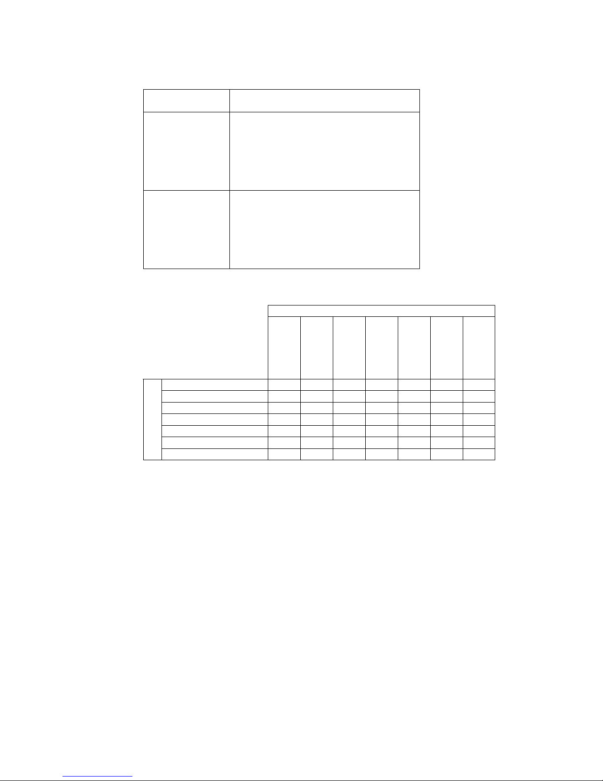
Communications Ports
Communications
port
Applicable communications method
Serial port A Host Link
1:1 NT link
1:N NT link
Memory link
(Bar-code reader input)
(Temperature controller connection)
(CX-Designer connection)
Serial port B Host Link
1:1 NT link
1:N NT link
Memory link
(Bar-code reader input)
(Temperature controller connection)
(CX-Designer connection)
The following table shows the communications methods that can be used in combination
when serial ports A and B are used at the same time.
Serial port B
Host Link
1:1 NT Link
1:N NT Link
Memory link
Bar-code
reader
Temperature
controller
CX-Designer
connection
Host Link YES YES YES YES YES YES YES
1:1 NT link YES YES YES YES YES YES YES
1:N NT Link YES YES YES YES YES YES YES
Memory link YES YES YES No YES YES YES
Bar-code reader YES YES YES YES No YES YES
Temperature controller YES YES YES YES YES YES YES
Serial port A
CX-Designer connection YES YES YES YES YES YES No
Page 6

5
Communications Setup
The following table shows the communications settings required at the NS-V1/V2 PT and the
host to connect to the host by means of Host Link communications.
Setup
location
Settings (See note 2.)
NS-V1/V2 PT Baud rate: 9,600 or 19,200 bps (See note 1.)
Host Start bits: 1 bit
Data: 7 bits
Stop bits: 2 bits
Parity: Even
Host Link unit number: 0
Baud rate: 9,600 or 19,200 bps (See note 1.)
Note 1: The baud rate settings must be the same for both the NS-V1/V2 PT and the host.
2: Use the 1:N protocol setting.
1-2-2 Applicable PLCs
The OMRON PLCs listed below can be connected as hosts using Host Link communications.
The connection can be made either directly to the built-in serial port on the CPU Unit or to a
Host Link Unit mounted to the PLC.
C Series
C200HS, C200HX/HG/HE(-Z), CQM1, CQM1H, CPM2A/CPM2C, CPM1/CPM1A, C500,
C1000H, C2000H
CV Series
CV500, CV1000, CV2000, CVM1
CS/CJ Series
CS1G/CS1H, CS1G-H/CS1H-H, CJ1G, CJ1G-H/CJ1H-H, CJ1M, CP1H/CP1L, CJ2H
Page 7

6
1-3 Connecting to the Host
The types of host that can be connected to a PT by using the serial ports on the NS-series PT
and connecting to an RS-232C port at the host are described here.
1-3-1 Connecting to an RS-232C Port at the Host
Compatible Host Units
Some models and series of OMRON PLCs have the host link function built in.
In the CS-series or CQM1H PLCs, the host link method can be used by installing a Serial
Communications Board. In addition, some C200HX/HG/HE(-Z)E have an integral CPU Unit
that can be connected in the host link method by installing a Communications Board.
Check the model and series of the PLC, the type of installed Serial Communications Board or
Serial Communications Unit before making a connection.
The PLC Units/Boards that can be connected to an NS-series PT through a Host Link
connection using RS-232C ports on both the PLC Unit/Board and PT are listed in the
following table.
PLC Series CPU Units with Built-in Host Link
Function
CPU Units Connectable with Host
Link Units or Expansion
Communications Board
Host Link Unit/
Communications
Board
CS1G-CPU42/43/44/45-EV1
CS1H-CPU63/64/65/66/67-EV1
CS1G-CPU42/43/44/45-EV1
CS1H-CPU63/64/65/66/67-EV1
CS Series
CS1G-CPU42H/43H/44H/45H
CS1H-CPU63H/64H/65H/66H/67H
CS1G-CPU42H/43H/44H/45H
CS1H-CPU63H/64H/65H/66H/67H
CS1W-SCU21-V1
CS1W-SCB21-V1
CS1W-SCB41-V1
CJ1G-CPU44/CPU45 CJ1G-CPU44/CPU45
CJ1G-CPU42H/43H/44H/45H
CJ1H-CPU65H/66H/67H
CJ1H-CPU65H/66H/67H-R
CJ2H-CPU64/65/66/67/68-EIP
CJ1G-CPU42H/43H/44H/45H
CJ1H-CPU65H/66H/67H
CJ1H-CPU65H/66H/67H-R
CJ2H-CPU64/65/66/67/68-EIP
CJ1M-CPU11/12/13/21/22/23 CJ1M-CPU11/12/13/21/22/23
CJ1W-SCU21/41-V1
CP1H-XA40DR-A/XA40DT-D/XA40D
T1-D/X40DR-A/X40DT-D/X40DT1-D/
Y20DT-D
CJ Series
CP1L-L14DR-A/L14DR-D/L14DT-D/L
14DT1-D/L20DR-A/L20DR-D/L20DTD/L20DT1-D/M30DR-A/M30DR-D/M3
0DT-D/M30DT1-D/M40DR-A/M40DRD/M40DT-D/M40DT1-D
CP1W-CIF01
C1000H-CPU01-EV1
C2000H-CPU01-EV1
C120-LK201-EV1
C200HS-CPU01/03/21/23/31/33-E
C200HE-CPU11/32/42-E
C200HE-CPU11/32/42-ZE
C200HG-CPU33/43/53/63-E
C200HG-CPU33/43/53/63-ZE
C200HX-CPU34/44/54/64-E
C200HX-CPU34/44/54/64/65/85-ZE
C200H-LK201-EV1
C200HS-CPU21/22/31/33-E
C200HE-CPU42-E
C200HE-CPU42-ZE
C200HE-CPU32/42-E
C200HE-CPU32/42-ZE
C200HG-CPU43/63-E
C200HG-CPU43/63-ZE
C200HG-CPU33/43/53/63-E
C200HG-CPU33/43/53/63-ZE
C Series
C200HX-CPU44/64-E
C200HX-CPU44/64/65/85-ZE
C200HX-CPU34/44/54/64-E
C200HX-CPU34/44/54/64/65/85-ZE
C200HW-COM02/04/
05/06-EV1
Page 8
7
PLC Series CPU Units with Built-in Host Link
Function
CPU Units Connectable with Host
Link Units or Expansion
Communications Board
Host Link Unit/
Communications
Board
C1000H-CPU01-EV1
C2000H-CPU01-EV1
C500-LK201-EV1
C1000H-CPU01-EV1
C1000HF-CPUA1-EV1
C2000H-CPU01-EV1
C500-LK203
CPM1-10/20/30CDR-@+CPM1-CIF01
CPM1A-10/20/30/40CD@-@+CPM1CIF01
CPM2A-30/40/60CD@@-@+CPM1CIF01 (Peripheral port connection)
CPM2C-10/20@@@@@@-@
(See note 1.)
CQM1-CPU21-E
CQM1-CPU41/42/43/44-EV1
C Series
CQM1H-CPU11/21/51/61 (See note 2.) CQM1H-CPU51/61 CQM1H-SCB41
CV500-CPU01-EV1 CV500-CPU01-EV1 CV500-LK201
CV1000-CPU01-EV1 CV1000-CPU01-EV1
CV Series
(See note 3.)
CV2000-CPU01-EV1 CV2000-CPU01-EV1
CVM1 Series
(See note 3.)
CVM1-CPU01-EV2
CVM1-CPU11-EV2
CVM1-CPU21-EV2
CVM1-CPU01-EV2
CVM1-CPU11-EV2
CVM1-CPU21-EV2
CV500-LK201
CompoBus/S
master control
unit
SRM1-C02-V2
Note 1: Use a CPM2C-CN111 or CS1W-CN114/118 Connecting Cable, CPM1-CIF01
RS-232C Adapter, or CPM1-CIF11 RS-422A Adapter to connect.
2: The CQM1H-CPU11 does not have a built-in RS-232C port, so connect to the
peripheral port to the PT with a CS1W-CN118 Connecting Cable.
3: CPU Units of CVM1/CV-series PLCs without the suffix –EV@ cannot be connected.
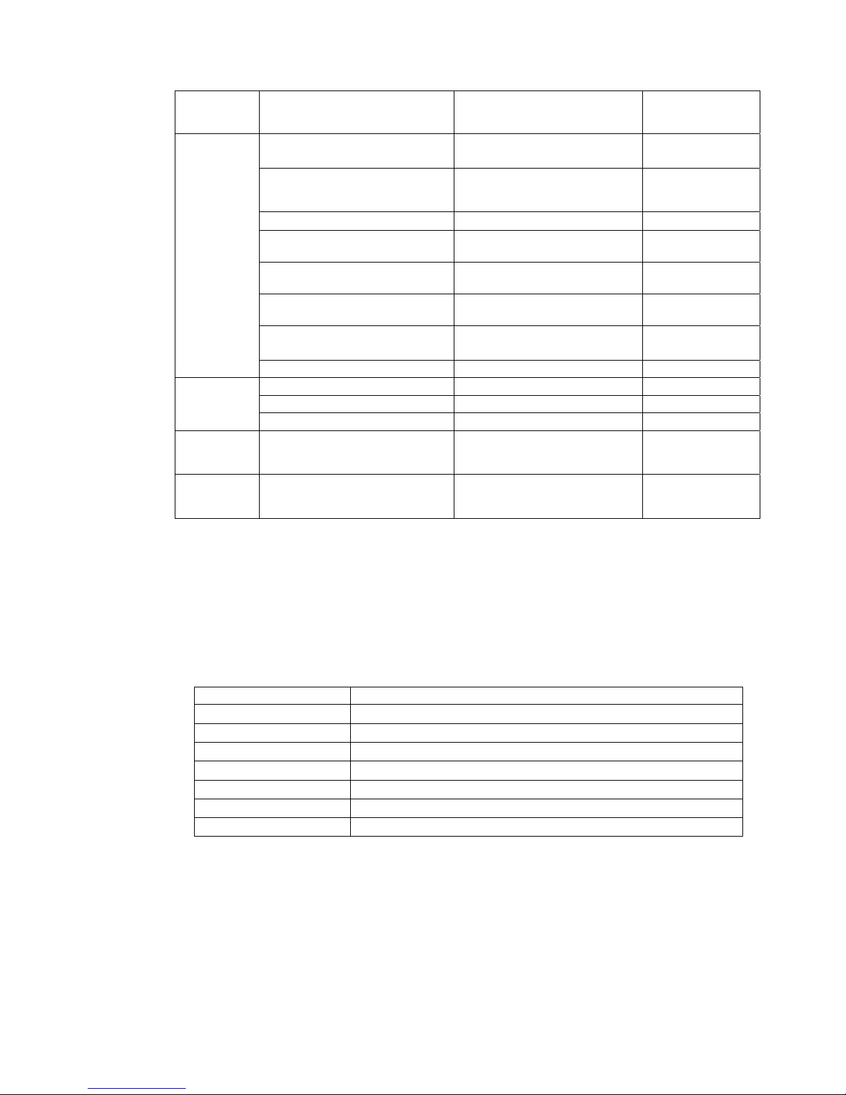
Settings at the Host
When using the host link method, the settings shown below must be made at the host
(depending on the unit, some of these settings may not be necessary, or settings not shown
here may be necessary).
Item Switch Setting
I/O port RS-232C
Communications speed Set the same baud rate as set at the NS-series PT (See note 1.)
Transfer code ASCII, 7 data bits, 2 stop bits
Parity Even
1-to-1/1-to-N 1-to-N (See note 2.)
Command level Level 1, 2, 3
Unit # 00
Note 1: Set the Host Link communications speed (baud rate) to 9600 bps or 19200 bps with
the Communications Setting menu item in the CX-Designer and the System Menu
for the NS-series PT. For details, refer to 1-4 Settings for Host Link.
2: The 1-to-N setting enables using a BCC (Block Check Character). It is not actually
possible to connect more than one NS-series PT in a single Host Link.
The setting methods for each type of unit are described in the following.
Page 9
8
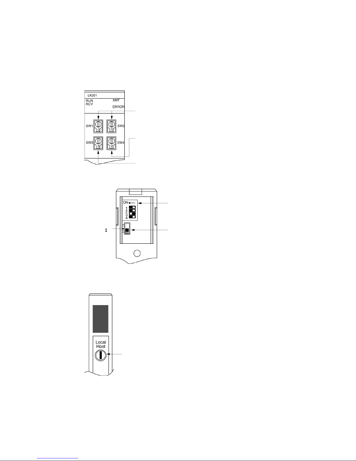
Connecting to a C-series Host Link Unit
C200H/C200HS/C200HE(-Z)E/C200HG(-Z)E/C200HX(-Z)E Rack-mounted type: C200H-LK201-V1
Setting the Front Switches
Set each switch with a flat blade screwdriver so that the values or symbols in the setting value
window agree with the following.
• Unit # (SW1, SW2)
Set these switches to 0.
• Command level, parity, and transfer code (SW4)
Set this switch to 2.
• Communications speed (SW3)
Set this switch to 5 to select 9600 bps.
Set this switch to 6 to select 19200 bps.
Setting the Rear Switches
• 1-to-1/1-to-N selection (DIP switch)
Set #3 to ON.
• CTS selection (selector switch)
Set this always to 0 V (ON).
CTS selector switch
External
0 V (ON)
C1000H/C2000H Rack-mounted type: C500-LK201-EV1
Setting the Front Switches
• Mode control (key switch)
Set this to host link.
Page 10
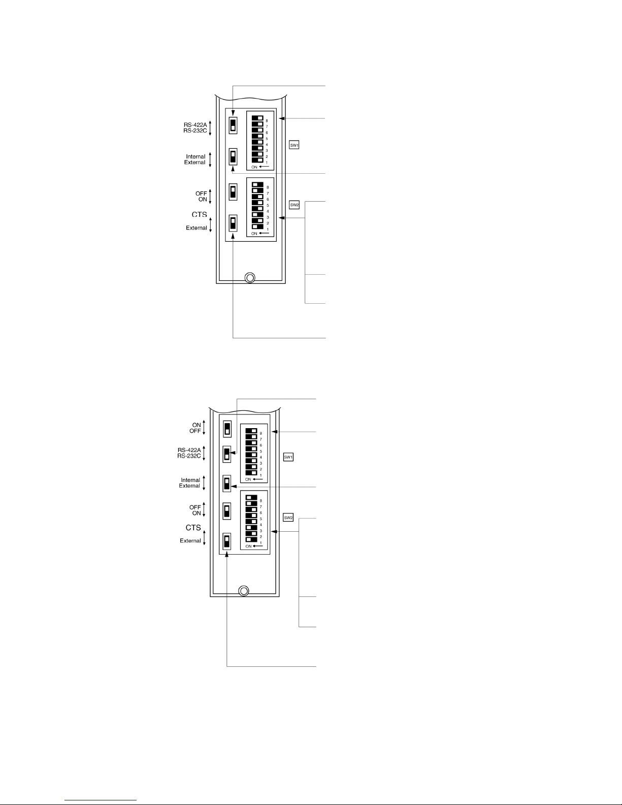
9
Setting the Rear Switches
• I/O port selection (selector switch)
Set this to RS-232C.
• Unit # (DIP SW1)
Set SW1-1 to SW1-5 to OFF (0).
• Synchronization (selector switch)
Set this to Internal.
• Communications speed
(DIP SW2-1 to SW2-4)
Set these switches to 0010 to select
19,200 bps.
Set these switches to 1010 to select
9,600 bps.
(0: OFF 1: ON)
• 1-to-1/1-to-N selection (DIP SW2-6)
Set SW2-6 to OFF (0) (1-to-N).
• Command level (DIP SW2-7, SW2-8)
Set these switches to ON (1).
(
Levels 1, 2, and 3 are enabled.
)
• CTS selection (selector switch)
Set this always to 0 V (ON).
I/O port
S
y
nchronization
Terminato
r
0 V
C1000H(F)/C2000H Rack-mounted type: C500-LK203
Setting the Rear Switches
• I/O port selection (selector switch)
Set this to RS-232C.
• Unit #, parity, and transfer code
(DIP SW1-1 to SW1-7)
Set SW1-1 to SW1-7 to OFF (0).
• Synchronization (selector switch)
Set this to Internal.
• Communications speed
(DIP SW2-1 to SW2-4)
Set these switches to 0010 to select
19,200 bps.
Set these switches to 1010 to select
9,600 bps.
(0: OFF 1: ON)
• 1-to-1/1-to-N selection (DIP SW2-6)
Set SW2-6 to OFF (0) (1-to-N).
• Command level (DIP SW2-7, SW2-8)
Set these switches to ON (1).
(
Levels 1, 2, and 3 are enabled.
)
• CTS selection (selector switch)
Set this always to 0 V (ON).
I/O port
S
y
nchronization
Terminato
r
5V suppl
y
0
V
Page 11
10
C200H/C1000H/C2000H CPU Unit-mounted Type: C120-LK201-EV
Setting the Rear Switches
• Unit #, parity, and transfer code
(DIP SW1-1 to SW1-5)
Set SW1-1 to SW1-5 to OFF (0).
* Parity is fixed at Even Parity. Transfer cod e
is fixed at ASCII 7 data bits and 2 stop bits.
• Communications speed (DIP SW2-1 to SW2-4)
Set these switch es to 0010 t o select 19200 bps.
Set these switches to 1010 to select 9600 bps.
(
0: OFF 1: ON
)
• 1-to-1/1-to- N selection (DIP SW2-6)
Set SW2-6 to OFF (0) (1-to-N).
• Command level (DIP SW2-7, SW2-8)
Set these switches to ON (1).
(Levels 1, 2, and 3 are enabled.)
• CTS selection (DIP SW3-1 and SW3-2)
Set SW3-1 to ON (1), and SW3-2 to OFF (0).
(Set this always to 0V.)
• Synchronizatio n (DIP SW3-3 to SW3-6)
Set SW3-3 and SW3-5 to ON (1), and
SW3-4 and SW3-6 to OFF (0) . (Set these t o Internal.)
Connecting to a CVM1/CV Series Host Link Unit
CVM1/CV-series Rack-mounted type: CV500-LK201
A CVM1/CV series host link unit (CV500-LK201) has two connectors (communications ports 1
and 2). Either of these ports can be used for connection to an NS-series PT by the RS-232C
method. However, since the connectors at these ports are of different types,
a cable that matches the connector must be prepared.
• Communications port 1
Communications port 1 is a 25-pin connector for RS-232C use only.
• Communications port 2
Communications port 2 is a 9-pin connector which allows selection of the RS-232C or
RS-422A method. When this port is used with the RS-232C method, the I/O port selector
switch on the front of the unit must be set to RS-232C (the upper position).
CPU Bus Unit Settings
When connecting to a CVM1/CV series host link unit, set the following communications
conditions for the CPU Bus Unit settings.
Item Setting at Host
Communications speed Set the same baud rate as set at the NS-series PT (See note 1.)
Transfer code ASCII, 7 data bits, 2 stop bits
Parity Even
1-to-1, 1-to-N 1-to-N (See note 2.)
Command level Level 1, 2, 3
Note 1: Set the Host Link communications speed (baud rate) to 9600 bps or 19200 bps with
the Communications Setting menu item in the CX-Designer and the System Menu
for the NS-series PT. For details, refer to 1-4 Settings for Host Link.
2: The 1-to-N setting enables using a BCC (Block Check Character). It is not actually
possible to connect more than one NS-series PT in a single Host Link.
Page 12
11
Set the CPU Bus Unit settings directly from a Programming Device (e.g. CX-Programmer).
For details on the CPU Bus Unit settings, refer to the SYSMAC CVM1/CV-series Host Link
Unit Operation Manual (W205-E1-@).
Setting The Front Switches
•
Unit # (SW3, SW4)
When using communication port 2, set these
switches to 0.
•
I/O port selection (selector switch)
Set this to RS-232C.
•
CTS selection (DIP SW2 and SW3)
Set SW2 or SW3 to ON. (Set this always to 0V.)
To use communication port 1, set SW2. To use
communication port 2, set SW3.
•
Communication condition setting (DIP SW1)
Set this switch to OFF.
Communication is executed in accordance with the
CPU bus unit system settings made at the PLC. The
initial values for the system settings are as follows.
- Communications speed: 9600 bps
- Parity: Even
- Xon/Xoff control: Not executed
- Communication method: Full duplex
- Stop bits: 2 stop bits
- Data length: 7 bits
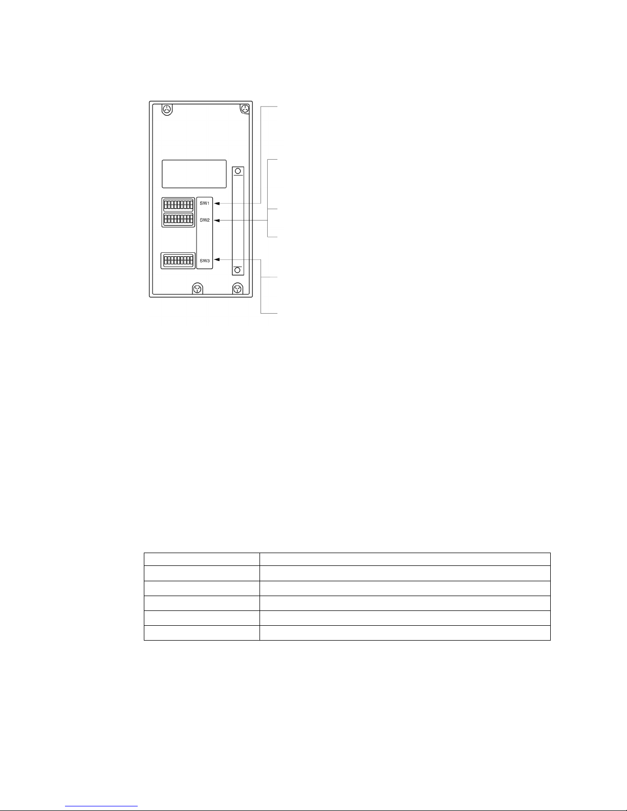
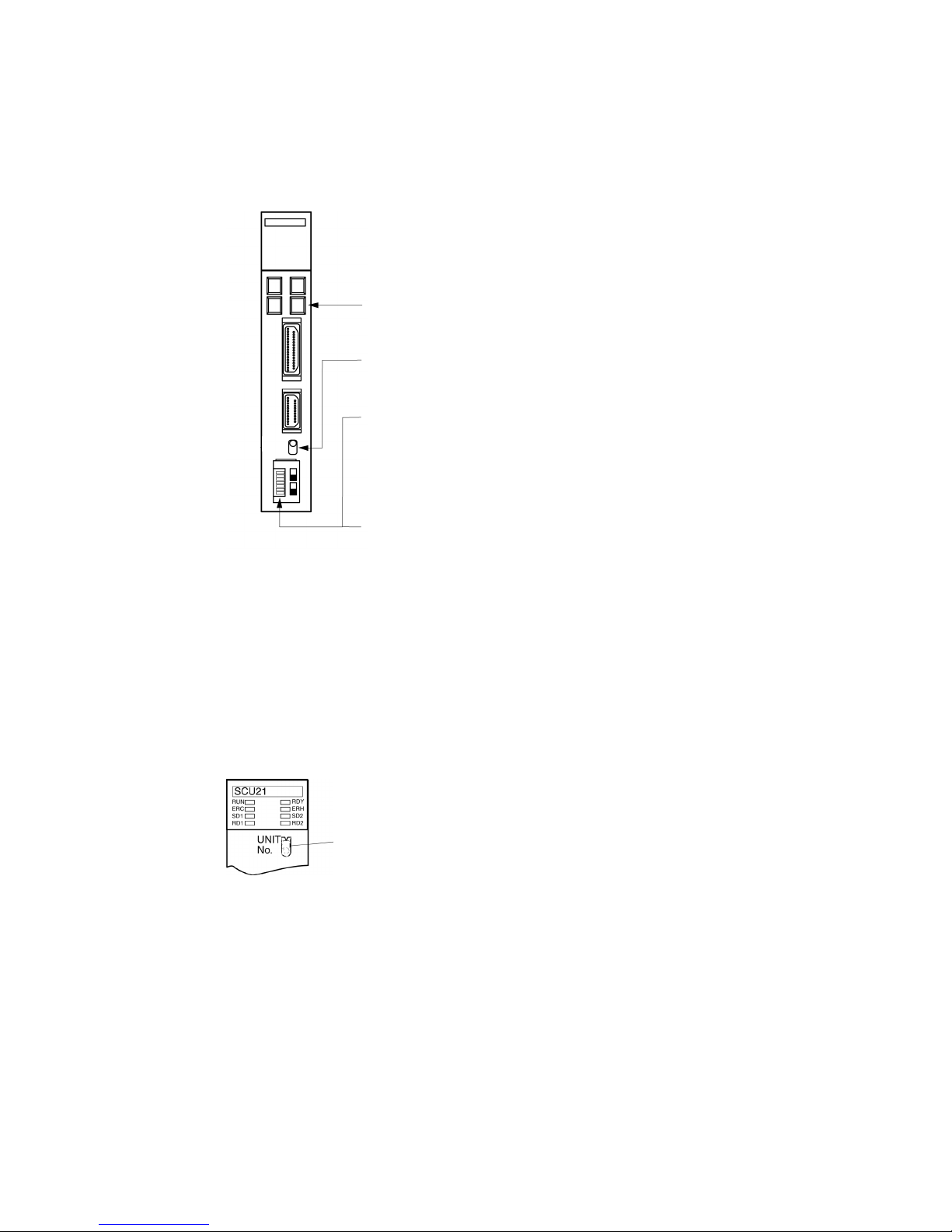
Connecting to a CS-series Serial Communications Unit
CS-series Rack-mounted type: CS1W-SCU21(-V1)
Setting the Front Switches
Set the unit number of the Serial Communications Unit by using the rotary switch located on
the front panel. Set each switch with a flat blade screwdriver so that the values or symbols in
the setting value window agree with the following.
Set the unit number to 0 through F so that it will
not overlap with the numbers used in other
units.
Allocation DM Area Settings in CPU Unit
Settings are written from the Programming Device (a Programming Console or
CX-Programmer) directly into the allocation DM area (system setting area) of the CPU Unit.
After the settings are written, they become effective by turning the power ON, restarting the
unit, restarting the communications port, or execution of the STUP command.
In the following, the words allocated in the DM area and the settings are shown.
Page 13

12
m = DM 30000 + 100
× unit number (word address)
Allocation DM area word
Port 1 Port 2
Writing
Value
Settings
m m+10 8000 Host link mode, 2 stop bits, even parity, data length
7 bits
0000 Communications speed 9600 bps. m+1 m+11
0007 Communications speed 19200 bps.
m+2 m+12 0000 Transmit delay time 0 ms.
m+3 m+13 0000 No CTS control Unit No.0 for host link
Connecting to a CJ-series Serial Communications Unit
CJ-series Rack-mounted Type: CJ1W-SCU21/41-V1
Setting the Front Switches
Set the unit number for the Serial Communications Unit using the rotary switch on the front of
the Unit. Follow the procedure below use a flat-head screwdriver (
−) to set the number and
sign in the setting display window.
Port 2 on the CJ1W-SCU41-V1 is an RS-232C port.
• Unit Number Setting
Set a number from 0 to
F that does not overlap
another unit.
• Port 1
RS-232C
• Port 2
RS-232C
CJ1W-SCU21-V1
• Unit Number Setting
Set a number from 0 to
F that does not overlap
another unit.
• Port 2
RS-232C
CJ1W-SCU41-V1
Setting CPU Unit Allocation DM Area Words
Settings can be directly written to the Allocation DM Area (System Setup Area) by using a
Programming Device, such as a Programming Console or the CX-Programmer. After the
settings are written, the settings will become valid by performing any of the following: turning
on the power supply again, restarting the Unit, restarting the communications port, or
executing a STUP instruction.
Page 14

13
The following table shows words allocated in the DM Area and setting details.
m = D30000 + 100
× unit number (word address)
Allocation DM area word
Port 1 Port 2
Writing Value Setting details
m m+10 8000 Host link mode, 2 stop bits, even parity,
7-bit data length
0000 Baud rate: 9,600 bps m+1 m+11
0007 Baud rate: 19,200 bps
m+2 m+12 0000 Transmission delay time: 0 ms
m+3 m+13 0000 No CTS control, Unit number 0 for host
link
Connecting to a CPU Unit
CV-series and CVM1/CV-series (-EV@) CPU Units
CV500-CPU01-EV1/CV1000-CPU01-EV1/CV2000-CPU01-EV1
CVM1-CPU01-EV2/CVM1-CPU11-EV2/CVM1-CPU21-EV2
PLC Setup
When connecting to a CVM1/CV series CPU Unit, set the following communications conditions for
the PLC Setup.
Item Setting at Host
Communications speed Set the same baud rate as set at the NS-series PT (See note.)
Stop bit 2 stop bits
Parity Even
Data length ASCII 7 bits
Unit # 00
Note: Set the Host Link communications speed (baud rate) to 9600 bps or 19200 bps with
the Communications Setting menu item in the CX-Designer and the System Menu for
the NS-series PT. For details, refer to 1-4 Settings for Host Link.
Either set PLC Setup directly from a Programming Device (e.g. CX-Programmer), or transmit
the PLC Setup made at a Programming Device to the CPU UNIT.
For details on the PLC Setup, refer to the SYSMAC CVM1/CV500/1000/2000 Operation
Manual: Ladder Diagrams (W202-E1-@).
Page 15

14
Setting the Front Switches
• I/O port selection (selector switch)
Set this to RS-232C.
I/O port selector switch
• System setting (DIP SW4)
To effect the existing DIP switch
settings, set SW4 to ON.
To effect the existing PC Setup, set
SW4 to OFF.
Note
For CPUs manufactured before or
during June 1995 (lot No. @@65), the
existing DIP switch settings differ from
the existing PC Setup as follows.
- DIP switch settings:
2,400 bps, 1 stop bit, even parity, 7
bit data length
- PC Setup:
9,600 bps, 2 stop bits, even parity, 7
bit data length
For CPUs manufactured from July 1995
onward (lot No. @@75), the stipulated
values in the DIP switch settings also
are 9,600 bps and 2 stop bits.
C-series C200HS, C200HX/HG/HE(-Z)E, CPM1, CPM2A, CPM2C, CQM1, CQM1H CPU Units, SRM1
The connection method depends upon the model of PLC being used, as shown in the following
table.
PLC model Connection method
C200HS, CQM1 Connect to the CPU Unit’s built-in RS-232C port.
C200HX/HG/HE(-Z)E
• Connect to the CPU Unit’s built-in RS-232C port.
• Connect to one of the RS-232C ports (port A or port B) on a Serial
Communications Board.
CQM1H
• Connect to the CPU Unit’s built-in RS-232C port.
• Connect to the peripheral port through a CS1W-CN118
Connecting Cable.
• Connect to the RS-232C port (port 1) on a Serial Communications
Board.
CPM1 Connect to the peripheral port through a CPM1-CIF01
RS-232C Adapter.
CPM2A, SRM1
• Connect to the CPU Unit’s built-in RS-232C port.
• Connect to the peripheral port through a CPM1-CIF01 RS-232C
Adapter.
CPM2C Connect to the CPU Unit’s RS-232C port or the peripheral port
through a Connecting Cable (CPM2C-CN111, CS1W-CN118,
or CS1W-CN114).
(The CPM2C-CN111 splits the Unit’s communications port into
an RS-232C port and a peripheral port. A CPM1-CIF01
RS-232C Adapter is also required to connect to this peripheral
port.)
PLC Setup Area Settings
When connecting to a C200HS, C200HX/HG/HE(-Z)E, CPM1, CPM2A, CPM2C, CQM1, or
CQM1H CPU Unit, or SRM1, set the following communications conditions for the PLC Setup
area.
Item Setting at Host
Communications mode Host link mode
Communications speed Set the same baud rate as set at the NS-series PT (See note.)
Stop bit 2 stop bits
Page 16

15
Item Setting at Host
Parity Even
Data length ASCII 7 bits
Unit # 00
Note: Set the Host Link communications speed (baud rate) to 9600 bps or 19200 bps with
the Communications Setting menu item in the CX-Designer and the System Menu for
the NS-series PT. For details, refer to 1-4 Settings for Host Link.
Set the PLC Setup area settings directly from a Programming Device (e.g. CX-Programmer).
For details on operations relating to the PLC Setup area, refer to the manual for the PLC
which is used.
The PLC Setup area word numbers and settings to be made depending on the unit and port
to which the connection is made are shown below.
CPM2A, CPM2C, CQM1H, or SRM1: Peripheral port connection
Word Writing Value Settings
DM6650 0001 Host link mode, no CTS control, communications conditions
set by the contents of DM
0303 Data length 7 bits, 2 stop bits, even parity, communications
speed: 9600 bps
DM6651
0304 Data length 7 bits, 2 stop bits, even parity, communications
speed: 19200 bps
DM6653 0000 Unit # 00
C200HS, C200HX/HG/HE(-Z)E, CPM2A, CPM2C, CQM1, CQM1H (other than the CPU11),
or SRM1: Built-in RS-232C port connection
Word Writing Value Settings
DM6645 0001 Host link mode, no CTS control, communications conditions
set by the contents of DM
0303 Data length 7 bits, 2 stop bits, even parity, communications
speed: 9600 bps
DM6646
0304 Data length 7 bits, 2 stop bits, even parity, communications
speed: 19200 bps
DM6648 0000 Unit # 00
C200HX/HG/HE(-Z)E: Serial Communications Board port A, CQM1H: Serial Communications
Board port 1
Word Writing Value Settings
DM6555 0001 Host link mode, no CTS control, communications conditions
set by the contents of DM area
0303 Data length 7 bits, 2 stop bits, even parity, communications
speed: 9600 bps
DM6556
0304 Data length 7 bits, 2 stop bits, even parity, communications
speed: 19200 bps
DM6558 0000 Unit # 00
Page 17

16
C200HX/HG/HE(-Z)E: Board Port B Connection
Word Writing Value Settings
DM6550 0001 Host link mode, no CTS control, communications conditions
set by the contents of DM
0303 Data length 7 bits, 2 stop bits, even parity, communications
speed: 9600 bps
DM6551
0304 Data length 7 bits, 2 stop bits, even parity, communications
speed: 19200 bps
DM6553 0000 Unit # 00
CPM1 Connection
Word Writing Value Settings
DM6650 0001 Host link mode, communications conditions set by the
contents of DM area
0303 Data length 7 bits, 2 stop bits, even parity, communications
speed: 9600 bps
DM6651
0304 Data length 7 bits, 2 stop bits, even parity, communications
speed: 19200 bps
DM6653 0000 Unit # 00
Connecting to a CPM2C
The CPM2C PLCs do not have the same kind of port connectors found on CS-series PLCs.
The CPM2C’s communications port handles both RS-232C and peripheral port connections
which are divided internally. Therefore, when using the CPM2C, it is necessary to select
RS-232C or peripheral port connections, according to the kind of cable and port (on the
cable) used, as shown in the following table. Refer to the CPM2C Operation Manual for more
details.
Port connecting to PT PLC Setup
RS-232C port (D-Sub 9-pin) of CPM2C-CN111 Built-in RS-232C port settings
Peripheral port of CPM2C-CN111 Peripheral port settings
RS-232C port (D-Sub 9-pin) of CS1W-CN118 Built-in RS-232C port settings
Peripheral port of CS1W-CN114 Peripheral port settings
Peripheral port
RS-232C port
(D-Sub 9-pin, female)
RS-232C port
(D-Sub 9-pin, female)
Peripheral port
Setting the DIP Switches of a C200HX/HG/HE(-Z)E, CQM1 or CQM1H
When using a C200HX/HG/HE(-Z)E, CQM1, or CQM1H the DIP switches on the front panel
must be set as shown below in order to make the settings in the PLC Setup area (data
memory) effective.
Page 18

17
RS-232C port communication condition setting
Set DIP SW5 to OFF to make the settings made in
PC Setup effective.
When using the CQM1H’s built-in peripheral port, turn ON SW7.
Setting the Switches of a CPM2A
When using a CPM2A, the switches on the front panel must be set as shown below in order to
make the PLC Setup settings effective.
Set the Communications
switch to OFF (down
position).
Setting the Switches of a CPM2C
When using a CPM2C, the switches on the front panel must be set as shown below in order to
make the PLC Setup settings effective.
The settings for SW1 and SW2 depend upon the usage of the peripheral
port and RS-232C port.
• Connecting PT to peripheral port
• Connecting PT to built-in RS-232C port
(A device that requires non-standard communications settings is
connected to the peripheral port.)
• Connecting PT to built-in RS-232C port
(A Programming Console is connected to the peripheral port.)
Setting the Switches on a RS-232C Adapter
When using a CPM1-CIF01 RS-232C Adapter, set the mode switch as shown in the following
diagram.
Set the mode setting switch to HOST (upper position).
Page 19

18
CS-series CPU Unit type: CS1G/H-CPU-EV1, CS1G/H-H
Connect to the built-in RS-232C port of the CPU Unit, or the RS-232C port of the
Communications Board. Note that the connection to a peripheral port must be made via an
RS-232C adapter (CS1W-CN118) specially designed for connecting to a peripheral port.
PLC Setup
When connecting to a CS-series CPU Unit, set the following communications conditions for
the PLC Setup area. Since the settings shown below are the PLC default settings for the CPU
Unit, no change to the PLC Setup is necessary as long as the communications speed is
maintained at 9600 bps.
Item Setting at Host
Communications speed Set the same baud rate as set at the NS-series PT (See note.)
Stop bits 2 stop bits
Parity Even
Data length ASCII 7 bits
Unit No. for the host link 00
Note: Set the Host Link communications speed (baud rate) to 9600 bps or 19200 bps with
the Communications Setting menu item in the CX-Designer and the System Menu for
the NS-series PT. For details, refer to 1-4 Settings for Host Link.
When the communications speed is set to 19200 bps., the PLC Setup of the CPU Unit
need to be changed.
Either set the PLC Setup directly from a Programming Device (Programming Console), or
transmit the PLC Setup made at a Programming Device (CX-Programmer) to the CPU Unit.
For details on PLC Setup, refer to the SYSMAC CS series Operation Manual (W339-E1-@).
When using the built-in RS-232C port of CS1G/H
Word # Writing Value Settings
160 8000 Host link mode, data length 7 bits, 2 stop bits, even parity
0000 Communications speed: 9600 bps. 161
0007 Communications speed: 19200 bps.
166 0000 Unit #00
When using the peripheral port of CS1G/H
Word # Writing Value Settings
144 8000 Host link mode, data length 7 bits, 2 stop bits, even parity
0000 Communications speed: 9600 bps. 145
0007 Communications speed: 19200 bps.
150 0000 Unit #00
Setting the Front Switches
Set the CPU Unit DIP switches to 4 or 5 in accordance with the port the NS-Series PT is
connected to.
Page 20

19
DIP switches (inside the battery storage)
• Set SW4 to ON (establishing communication in
accordance with PC Setup) when connecting the NSseries PT to a peripheral port.
• Set SW5 to OFF (establishing communication in
accordance with PC Setup) when connecting the NSseries PT to an RS-232C port.
Peripheral port
This is used mainly for
connection to the
Programming Device.
(This also supports the
RS-232C unit connection.)
RS-232 port
This is used mainly for
connection to the RS-232C
unit.
(This also supports the
CX-Programmer.)
Connecting to CS1 Series Serial Communications Board
Serial Communications Board equipped with an RS-232C port for CS-series CPU Units:
CS1W-SCB41/21-V1
Allocation DM Area Settings in CPU Unit
Settings are written from the Programming Device (a Programming Console or
CX-Programmer) directly into the allocation DM area (system setting area) of the CPU Unit.
After the settings are written, they become effective by turning the power ON, restarting the
unit, restarting the communications port, or execution of the STUP command.
In the following, the words allocated in the DM area and the settings are shown.
Allocation DM area word
Port 1 Port 2
Writing Value Settings
D32000 D32010 8000 Host link mode, 2 stop bits, even parity,
data length 7 bits
0000 Communications speed 9600 bps. D32001 D32011
0007 Communications speed 19200 bps.
D32002 D32012 0000 Transmit delay time 0 ms.
D32003 D32013 0000 No CTS control, Unit No. 0 for host link
1-3-2 Connecting to an RS-422A/485 Port at the Host
Compatible Host Units
Some models and series of OMRON PLCs have the RS-422A type host link function built in.
With the CS-series and CQM1H, the host link method can be used by installing a serial
Communications Board. In addition, some C200HX/HG/HE(-Z)E devices have an integral
CPU Unit that can be connected in the host link method by installing a Communications
Board.
With the CPM2A and CPM2C, an RS-422A type of 1:1 NT Link can be created through a
CPM1-CIF11 RS-422A Adapter.
Page 21

20
Check the model and series of the PLC and the type of the installed Board or Unit before
making a connection.
The PLC Units that provide an RS-422A Host Link interface and that can be connected to an
NS-series PT port to which an RS-232C/RS422A Link Adaptor (NS-AL002) is connected are
listed in the following table.
PLC
Series
CPU Units with Built-in Host Link
Function
CPU Units Connectable with
Host Link Units or Expansion
Communications Board
Host Link Unit/
Communications Board
CS1G-CPU42/43/44/45-EV1
CS1H-CPU63/64/65/66/67-EV1
CS
Series
CS1G-CPU42H/43H/44H/45H
CS1H-CPU63H/64H/65H/66H/
67H
CS1W-SCB41-V1
CJ1G-CPU44/CPU45
CJ1G-CPU42H/43H/44H/45H
CJ1H-CPU65H/66H/67H
CJ1H-CPU65H/66H/67H-R
CJ2H-CPU64/65/66/67/68-EIP
CJ1M-CPU11/12/13/21/22/23
CJ1W-SCU41-V1
CP1H-XA40DR-A/XA40DT-D/XA
40DT1-D/X40DR-A/X40DT-D/X4
0DT1-D/Y20DT-D
CJ
Series
CP1L-L14DR-A/L14DR-D/L14DT-
D/L14DT1-D/L20DR-A/L20DR-D/
L20DT-D/L20DT1-D/M30DR-A/M
30DR-D/M30DT-D/M30DT1-D/M
40DR-A/M40DR-D/M40DT-D/M4
0DT1-D
CP1W-CIF11
C1000H-CPU01-EV1
C2000H-CPU01-EV1
C120-LK202-EV1
C200HS-CPU01/03/21/23/31/33-E
C200HE-CPU11/32/42-E
C200HE-CPU11/32/42-ZE
C200HG-CPU33/43/53/63-E
C200HG-CPU33/43/53/63-ZE
C200HX-CPU34/44/54/64-E
C200HXCPU34/44/54/64/65/85-ZE
C200H-LK202-EV1
C200HE-CPU32/42-E
C200HE-CPU32/42-ZE
C200HG-CPU33/43/53/63-E
C200HG-CPU33/43/53/63-ZE
C200HX-CPU34/44/54/64-E
C200HXCPU34/44/54/64/65/85-ZE
C200HW-COM03/06-EV1
C1000H-CPU01-EV1
C2000H-CPU01-EV1
C500-LK201-EV1
C1000H-CPU01-EV1
C1000HF-CPUA1-EV1
C2000H-CPU01-EV1
C500-LK203
CPM1-10/20CDR-@+CPM1-CIF11
C
Series
CPM1A-10/20/30/40CD@-@+CPM1-CIF11
Page 22

21
PLC
Series
CPU Units with Built-in Host Link
Function
CPU Units Connectable with
Host Link Units or Expansion
Communications Board
Host Link Unit/
Communications Board
CPM2A-30/40/60CD@@-@+CPM1-CIF11
(Peripheral port connection)
CPM2C-10/20@@@@@@-@ (See note 1.)
C
Series
CQM1H-CPU51/61 CQM1H-SCB41
CV500-CPU01-EV1 CV500-CPU01-EV1
CV1000-CPU01-EV1 CV1000-CPU01-EV1
CV
Series
(See
note
2.)
CV2000-CPU01-EV1 CV2000-CPU01-EV1
CV500-LK201
CVM1
Series
(See
note
2.)
CVM1-CPU01-EV2
CVM1-CPU11-EV2
CVM1-CPU21-EV2
CVM1-CPU01-EV2
CVM1-CPU11-EV2
CVM1-CPU21-EV2
CV500-LK201
SRM1 SRM1-C02-V2+CPM1-CIF11
Note 1: Use a CPM2C-CN111 or CS1W-CN114/118 Connecting Cable, CPM1-CIF01
RS-232C Adapter, or CPM1-CIF11 RS-422A Adapter to connect.
2: CPU Units of CVM1/CV-series PLCs without the suffix -EV@ cannot be connected.
The RS-485 interface (2-wire method) provided by NS-series PTs is for connecting to an
OMRON Temperature Controller. Do not connect it to an NS-series PT or PLCs using RS-485.
Settings at the Host
When using the RS-422A type host link method, the settings shown below must be made at
the host (depending on the unit, some of these settings may not be necessary, or settings not
shown here may be necessary).
Item Setting at Host
I/O port RS-422A
Communications speed Set the same baud rate as set at the NS-series PT (See note 1.)
Transfer code ASCII, 7 data bits, 2 stop bits
Parity Even
1-to-1/1-to-N 1-to-N (See note 2.)
Command level Level 1, 2, 3
Unit # 00
Note 1: Set the Host Link communications speed (baud rate) to 9600 bps or 19200 bps with
the Communications Setting menu item in the CX-Designer and the System Menu
for the NS-series PT. For details, refer to 1-4 Settings for Host Link.
2: The 1-to-N setting enables using a BCC (Block Check Character). It is not actually
possible to connect more than one NS-series PT in a single Host Link.
The setting methods for each type of unit are described in the following.
Page 23

22
Connecting to a C Series Host Link Unit
C200H/C200HS/C200HE(-Z)E/C200HG(-Z)E/C200HX(-Z)E Rack-mounted Type: C200H-LK202-V1
Setting the Front Switches
Set each switch with a flat blade screwdriver so that the values or symbols in the setting value
window agree with the following:
• Unit # (SW1, SW2)
Set these switches to 0.
• Command level, parity, and transfer code (SW4)
Set this switch to 2.
• Communications speed (SW3)
Set this switch to 5 to select 9600 bps.
Set this switch to 6 to select 19200 bps.
Setting the Rear Switches
• Terminator setting (selector switch)
Set this switch to ON.
• 1-to-1/1-to-N protocol selection (selector switch)
Set this switch to 1-to-N (OFF).
Terminator
Page 24

23
C1000H/C2000H Rack-mounted Type: C500-LK201-EV1
Setting the Front Switches
• Mode selector (key switch)
Set this to Host link.
Setting the Rear Switches
• I/O port selection (selector switch)
Set this to RS-422A.
• Unit # (DIP SW1)
Set SW1-1 to SW1-5 to OFF (0).
• Synchronization (selector switch)
Set this to Internal.
• Communications speed
(DIP SW2-1 to SW2-4)
Set these switches to 0010 to select
19200 bps.
Set these switches to 1010 to select
9600 bps.
(0: OFF 1: ON)
• 1-to-1/1-to-N selection (DIP SW2-6)
Set SW2-6 to OFF (0) (1-to-N).
• Command level (DIP SW2-7, SW2-8)
Set these switches to ON (1).
(Levels 1, 2, and 3 are enabled.)
• CTS selection (selector switch)
Set this always to 0 V (ON).
• Terminator setting (selector switch)
Set this switch to ON.
I/O port
Synchronization
Terminator
0 V
Page 25

24
C1000H(F)/C2000H Rack-mounted Type: C500-LK203
Setting the Rear Switches
• I/O port selection (selector switch)
Set this to RS-422A.
• Unit #, parity, and transfer code
(DIP SW1-1 to SW1-7)
Set SW1-1 to SW1-7 to OFF (0).
• Synchronization (selector switch)
Set this to Internal.
• Communications speed
(DIP SW2-1 to SW2-4)
Set these switches to 0010 to select
19,200 bps.
Set these switches to 1010 to select
9,600 bps.
(0: OFF 1: ON)
• 1-to-1/1-to-N selection (DIP SW2-6)
Set SW2-6 to OFF (0) (1-to-N).
• Command level (DIP SW2-7, SW2-8)
Set these switches to ON (1).
(Levels 1, 2, and 3 are enabled.)
• CTS selection (selector switch)
Set this always to 0 V (ON).
• Terminator setting (selector switch)
Set this switch to ON.
I/O port
Synchronization
Terminator
5V supply
0
V
C200H/C1000H/C2000H CPU-mounted Type: C120-LK202-EV1
Setting the Rear Switches
• Unit #, parity, and transfer code
(DIP SW1-1 to SW1-5)
Set SW1-1 to SW1-5 to OFF (0).
* Parity is fixed at Even Parity. Transfer code
is fixed at ASCII 7 data bits and 2 stop bits.
• Communications speed (DIP SW2-1 to SW2-4)
Set these switches to 0010 to select 19200 bps.
Set these switches to 1010 to select 9600 bps.
(0: OFF 1: ON)
• 1-to-1/1-to-N selection (DIP SW2-6)
Set SW2-6 to OFF (0) (1-to-N).
• Command level (DIP SW2-7, SW2-8)
Set these switches to ON (1).
(Levels 1, 2, and 3 are enabled.)
• Terminator setting (DIP SW3-1 to SW3-6)
Set SW3-1, SW3-3, and SW3-5 to ON (1).
Set SW3-2, SW3-4, and SW3-6 to OFF (0).
(Set terminator ON.)
Page 26

25
Connecting to a CVM1/CV Series Host Link Unit
CVM1/CV series Rack-mounted Type: CV500-LK201
A CVM1/CV series host link unit (CV500-LK201) has two connectors (communications ports 1
and 2). To use the RS-422A type host link method, set communications port 2 to RS-422A.
Communications port 2 is a 9-pin connector which allows selection of the RS-232C or
RS-422A method. When this port is used with the RS-422A method, the I/O port selector
switch on the front of the unit must be set to RS-422A (the lower position).
CPU Bus Unit Settings
When connecting to a CVM1/CV series host link unit, set the following communications
conditions for the CPU Bus Unit settings.
Item Setting at Host
Communications speed Set the same baud rate as set at the NS-series PT (See note 1.)
Transfer code ASCII, 7 data bits, 2 stop bits
Parity Even
1-to-1/1-to-N 1-to-N (See note 2.)
Command level Level 1, 2, 3
Note 1: Set the Host Link communications speed (baud rate) to 9600 bps or 19200 bps with
the Communications Setting menu item in the CX-Designer and the System Menu
for the NS-series PT. For details, refer to 1-4 Settings for Host Link.
2: The 1-to-N setting enables using a BCC (Block Check Character). It is not actually
possible to connect more than one NS-series PT in a single Host Link.
Set the CPU Bus Unit settings directly from a Programming Device (e.g., CX-Programmer).
For details on the CPU Bus Unit settings, refer to the SYSMAC CVM1/CV-series Host Link
Unit Operation Manual (W205-E1-@).
Page 27

26
Setting the Front Switches
• Unit # (SW3, SW4)
Set these switches to 0.
• I/O port selection (selector switch)
Set this to RS-422A.
• Communication condition setting (DIP SW1)
Set this switch to OFF.
Communication is executed in accordance
with the CPU bus unit system settings made
at the PLC. The initial values for the system
settings are as follows.
- Communications speed: 9,600 bps
- Parity: Even
- Xon/Xoff control: Not executed
- Communication method: Full duplex
- Stop bits: 2 stop bits
- Data length: 7 bits
• Terminator setting (selector switch)
Set this to ON.
Communications port 1
(RS-232C)
Communications port 2
(RS-232C/RS-422A)
I/O port selector switch
Connecting to a CPU Unit
CVM1/CV-series (-EV@) CPU Units
• CV500-CPU01-EV1/CV1000-CPU01-EV1/CV2000-CPU01-EV1
• CVM1-CPU01-EV2/CVM1-CPU11-EV2/CVM1-CPU21-EV2
PLC Setup
When connecting to a CVM1/CV-series CPU Unit, set the following communications
conditions for the PLC Setup.
Item Setting at Host
Communications speed Set the same baud rate as set at the NS-series PT (See note.)
Stop bit 2 stop bits
Parity Even
Data length ASCII 7 bits
Unit # 00
Note: Set the Host Link communications speed (baud rate) to 9600 bps or 19200 bps with
the Communications Setting menu item in the CX-Designer and the System Menu for
the NS-series PT. For details, refer to 1-4 Settings for Host Link.
Either set the PLC Setup directly from a Programming Device (e.g. CX-Programmer), or
transmit the PLC Setup made at a Programming Device to the CPU Unit.
For details on the PLC Setup, refer to the SYSMAC CVM1/CV500/CV1000/ CV2000
Operation Manual: Ladder Diagrams (W202-E1-@).
Page 28

27
Setting the Front Switches
• I/O port selection (selector switch)
Set this to RS-422A.
• Communication type setting (DIP SW3)
Set SW3 to OFF.
(for host link communication)
• Host link default value settings
(DIP SW4)
To effect the existing DIP switch settings,
set SW4 to ON.
To effect the values set in the PC Setup,
set SW4 to OFF.
Note
For CPUs manufactured before or
during June 1995 (lot No. @@65), the
existing DIP switch settings differ from
the PC Setup default values as follows.
- Existing DIP switch settings:
2,400 bps, 1 stop bit, even parity, 7 bit
data length
- PC Setup default values:
9,600 bps, 2 stop bits, even parity, 7
bit data length
For CPUs manufactured from July 1995
onward (lot No. @@75), the stipulated
values in the DIP switch settings also
are 9600 bps and 2 stop bits.
• Terminator setting (DIP SW6)
Set this switch to ON.
(Set terminator ON.)
I/O port selector switch
C-series C200HX/HG/HE(-Z)E, CPM1, CPM2A, CPM2C, CQM1H, CPU Unit
or SRM1
The connection method depends upon the model of PLC being used, as shown in the
following table.
PLC model Connection method
C200HX/HG/HE(-Z)E
• Connect to the RS-422A port (port A) on a Communications Board.
CQM1H
• Connect to the RS-422A port (port 2) on a Serial Communications
Board.
CPM1
• Connect to the peripheral port through a CPM1-CIF11 RS-422A
Adapter.
CPM2A, SRM1
• Connect to the peripheral port through a CPM1-CIF11 RS-422A
Adapter.
CPM2C
• Connect to the peripheral port (on a CPM2C-CN111 or
CS1W-CN114 Connecting Cable) through a CPM1-CIF11 RS-422A
Adapter.
(The CPM2C-CN111 splits the Unit’s communications port into a
RS-232C port and a peripheral port.)
Reference
• There are no Communications Boards for the
C200HX/HG/HE(-Z)E in which port B is the RS-422A port.
• There are no Serial Communications Boards for the
CQM1H in which port 1 is the RS-422A port.
Page 29

28
PLC Setup Area Settings
When connecting to a C200HX/HG/HE(-Z)E or CPM1, CPM2A, CPM2C, CQM1H CPU Units
or SRM1, set the following communications conditions for the PLC Setup area.
Item Setting at Host
I/O port RS-422A
Communications mode Host link mode
Communications speed Set the same baud rate as set at the NS-series PT (See note.)
Stop bit 2 stop bits
Parity Even
Data length ASCII 7 bits
Unit # 00
Note: Set the Host Link communications speed (baud rate) to 9600 bps or 19200 bps with
the Communications Setting menu item in the CX-Designer and the System Menu for
the NS-series PT. For details, refer to 1-4 Settings for Host Link.
Set the PLC Setup area settings directly from a Programming Device (e.g. CX-Programmer).
For details on operations relating to the PLC Setup area, refer to the manual for the PLC
which is used.
The PLC Setup area word numbers and settings to be made depending on the unit to which
the connection is made are shown below.
When using port A of the Communications Board of C200HX/HG/HE(-Z)E
Word # Writing Value Settings
DM6555 0001 Host link mode, no CTS control, communications
conditions set by the contents of DM area
0303 Data length 7 bits, 2 stop bits, even parity,
communications speed: 9600 bps
DM6556
0304 Data length 7 bits, 2 stop bits, even parity,
communications speed: 19200 bps
DM6558 0000 Unit # 00
When using a CPM1, CPM2A, CPM2C, SRM1
Word # Writing Value Settings
DM6650 0001 Host link mode, no CTS control, communications
conditions set by the contents of DM area
0303 Data length 7 bits, 2 stop bits, even parity,
communications speed: 9600 bps
DM6651
0304 Data length 7 bits, 2 stop bits, even parity,
communications speed: 19200 bps
DM6653 0000 Unit # 00
Page 30

29
When using a CQM1H
Word # Writing Value Settings
DM6550 0001 Host link mode, no CTS control, communications
conditions set by the contents of DM area
0303 Data length 7 bits, 2 stop bits, even parity,
communications speed: 9600 bps
DM6551
0304 Data length 7 bits, 2 stop bits, even parity,
communications speed: 19200 bps
DM6553 0000 Unit # 00
Connecting to a CPM2C
The CPM2C PLCs do not have the same kind of port connectors found on CS-series PLCs.
The CPM2C’s communications port handles both RS-232C and peripheral port connections
which are divided internally. Therefore, when using the CPM2C, it is necessary to select
RS-232C or peripheral port connections, according to the kind of cable and port (on the
cable) used, as shown in the following table. Refer to the CPM2C Operation Manual for more
details.
Peripheral port
RS-232C port
(
D-Sub 9-pin, female
)
Peripheral port
Setting Switches on a C200HX/HG/HE(-Z)E Communications Board
Set the switches on a C200HX/HG/HE(-Z)E Communications Board as follows.
Switch 1: Set to 4 (4-wire type, for RS-422A)
Switch 2: Set to ON for terminator ON (termination resistance applied)
Setting Switches on a CQM1H Serial Communications Board
Set the switches on a CQM1H Serial Communications Board as follows.
2-wire/4-wire selection (WIRE): Set to 4 (4-wire type, for RS-422A)
Terminator (TERM): Set to ON for termination ON (termination resistance applied).
Serial Communications Board
(
Inner Board slot 1
)
Terminator Switch (TERM)
Set to ON
(rig
ht side).
2-wire/4-wire Selection Switch
(WIRE)
Set to 4 (right side).
Page 31

30
Setting the Switches on an RS-422A Adapter
Set the terminator selector switch
to ON
(upp
er position).
Connecting to a CS-series Serial Communications Board
Serial Communications Board with an RS-422A/485 port equipped for CS-series
CPU Unit Type: CS1W-SCB41(-V1) (The port 2 is an RS-422A/485 port.)
Allocation DM Area Settings in CPU Unit
Settings are written from the Programming Device (a Programming Console or
CX-Programmer) directly into the allocation DM area (system setting area) of the CPU Unit.
After the settings are written, they become effective by turning the power ON, restarting the
unit, restarting the communications port, or executing the STUP command.
In the following, the words allocated in the DM area and the settings are shown.
Allocation DM area word
Port 2
Writing Value Settings
D32010 8000 Host link mode, 2 stop bits, data length 7 bits,
even parity,
0000 Communications speed 9600 bps. D32011
0007 Communications speed 19200 bps.
D32012 0000 Transmit delay time 0 ms.
D32013 0000 No CTS control, Unit No. 0 for host link
Page 32

31
Connecting to a CJ-series Serial Communications Unit
CJ-series Rack-mounted Serial Communications Unit: CJ1W-SCU41-V1
(Port 1 is an RS-422A/ 485 port.)
Setting the Front-panel Switches
Set the unit number for the Serial Communications Unit using the rotary switch on the front
panel of the Unit. Use a flat-head screwdriver to set the unit number in the setting display
window.
Set the terminator switch to ON (right side).
Set the 2-wire/4-wire selection switch to 4 (right side).
• Terminator Switch (TERM)
Set to ON (right side).
• Unit Number Setting
Set a number between 0 and F. Do not
set a number used by another Unit.
• 2-wire/4-wire Selecti on Switch
(WIRE)
Set to 4 (right side).
• Port 1
RS-422A/485
Setting Parameters Allocated in the DM Area in the CPU Unit
Settings can be directly written to the words allocated to the Serial Communications Unit in
the DM Area (System Setup Area) by using a Programming Device, such as a Programming
Console or the CX-Programmer. Any changes to the settings can be enabled by cycling the
power supply, restarting the Unit, restarting the communications port, or executing a STUP
instruction.
The following table lists the words allocated in the DM Area and setting details.
M = D30000 + 100
× unit number (word address)
Allocation DM Area word
Port 1 Port 2
Write value Setting details
m M+10 8000
Host Link mode, 2 stop bits, even parity,
7-bit data
0000 Baud rate: 9,600 bps M+1 M+11
0007 Baud rate: 19,200 bps
M+2 M+12 0000 Transmission delay time: 0 s
M+3 M+13 0000 No CTS control, unit number 0 for Host
Link
Page 33

32
1-4 Settings for Host Link
This section describes the procedure for making the NS-V1 PT settings for connecting to the
host by means of Host Link communications.
Use either serial port A or B. The flow of operations for connecting to the host is as follows:
(1) Design the screen data.
(2) Transfer the screen data.
(3) Set the communications method for serial port A or B
(4) Connect to the host.
1-4-1 Designing the Screen Data
Use the CX-Designer to create the screen data. First, select Communication Setting from
the PT Menu to display the Communication Setting Dialog Box.
Select Serial Port A or Serial Port B. Then set the serial port to PLC and the protocol to Host
Link.
1-4-2 Transferring Screen Data
Use the transfer program to transfer the screen data to the NS-V1/V2 PT.
For details on transferring screen data, refer to Transferring Data to the PT in the
CX-Designer online help.
1-4-3 Setting the Communications Method for Serial Port A or B
This procedure is not required if the method has already been set in 1-4-1 Designing the
Screen Data above. At the NS-V1/V2 PT, set Host Link as the communications method for the
serial port that is to be used to connect to the host by means of Host Link communications.
Also set the baud rate to same value as the host.
These settings are made from the NS-V1/V2 PT’s System Menu.
Page 34

33
(1) Press the Comm. Tab in the System Menu to display the Communications Setup Screen.
(For the NS5 PT, press the Comm. Button in the System Menu to display the screen, and
then press the
← and → Screen Switching Buttons to display the screen for page (2/3).
(2) Press the drop-down menu button and set Host Link as the communications method for
serial port A or B.
(3) Press the Detail Button to display the Host Link settings, and select Comm. Speed.
(4) Press the Write Button and press the Yes Button on the following dialog boxes to restart
the NS-V1/V2.
NS12/NS10/NS8-V1/V2 PT
(The screen is somewhat different for the NS12.)
NS5
Page 35

34
1-4-4 Connecting to the Host
Connect in the same way as for a 1:1 NT Link, and use the same cables that are used for a
1:1 NT Link connection.
If cables must be prepared, refer to the relevant manuals for the PLC or Host Link Unit, and to
the NS Series Setup Manual (Cat. No. V083).
Page 36

35
1-5 PLC Areas That Can Be Used for Communications
OMRON C-series PLCs
PLC model
Common I/O Area
(CIO)
Holding Relay
(HR)
Auxiliary Relay
(AR)
Link Relay (LR)
Timer/Counter
Area (TIM/CNT)
Data Memory
Area (DM)
EM Area (Current
bank) (EM)
C200HS -
C200HE/HG/HX(-Z)
00000
to
00511
00000
to
00099
00000
to
00027
00000
to
00063
00000
to
00511
00000
to
06655
07000
to
09999
00000
to
06143
C500 00000
to
00063
00000
to
00031
- 00000
to
00031
00000
to
00127
00000
to
00511
-
C1000H 00000
to
04095
-
C2000H
CQM1
00000
to
06655
-
CQM1H
00000
to
00255
00000
to
00099
00000
to
00027
00000
to
00063
00000
to
00511
00000
to
06655
00000
to
06143
CPM1/CPM1A 00000
to
00019
00200
to
00255
00000
to
00015
00000
to
00127
00000
to
01023
06144
to
06655
-
Ladder type PLCs
CPM2A/CPM2C 00000
to
00049
00200
to
00255
00000
to
00019
00000
to
00023
00000
to
00015
00000
to
00255
00000
to
02047
06144
to
06655
-
Page 37

36
CVM1/CV-series PLCs
PLC model
Common I/O Area (CIO)
Holding Relay (HR)
(See note 1.)
Auxiliary Relay (AR)
Link Relay (LR)
Timer/Counter Area
(TIM/CNT)
Data Memory Area
(DM)
EM Area (Current bank)
(EM) (See note 2.)
CV500
CVM1-CPU01-V@
00000
to
02555
- 00000
to
00511
- 00000
to
00511
00000
to
08191
-
CVM1-CPU11-V@
00000
to
02555
- 00000
to
00511
- 00000
to
01023
00000
to
09999
-
CV1000
CV2000
CVM1-CPU11-V@
CVM1-CPU21-V@
00000
to
02555
- 00000
to
00511
- 00000
to
01023
00000
to
09999
-
Note 1: The HR Area is included in the CIO Area. To use the HR Area, specify the CIO Area.
2: Do not use this area for creating screens. It cannot be used with Host Link
communications.
OMRON CS/CJ-series PLCs
PLC model
Common I/O
Area (CIO)
Holding Relay
(HR)
Auxiliary Relay
(AR)
Link Relay (LR)
Timer/Counter
Area (TIM/CNT)
Data Memory
Area (DM)
EM Area (Current
bank)
(
See note 1.
)
00000
to
06143
00000
to
00511
00000
to
00959
- 00000
to
02047
00000
to
09999
00000
to
09999
Work Area (WR)
(See note 2.)
CS1G/H(-H)
CJ1G/H(-H)
CJ1M
CP1L
CP1H
CJ2H
-
Note 1: The EM Area cannot be specified for the CJ1M.
2: Do not use this area for creating screens. It cannot be used with Host Link
communications.
Page 38

37
1-6 Restrictions
Applicable Project Versions
When connecting to the host by means of Host Link communications, use version 6.0 or later
for creating the screen data (project) to be transferred to the NS-V1/V2 PT.
To use a project of version 5.x or earlier, first use CX-Designer to convert the project to
version 6.0 or later before transferring it to the NS-V1/V2 PT.
Applicable Serial Ports
Either NS-V1/V2 serial port A or B can be used to connect to the host by means of Host Link
communications.
Applicable NS Models
Only NS-series PT models with a -V1/V2 suffix can be used to connect to the host by means
of Host Link communications. NS-series PT models without the -V1/V2 suffix cannot be
connected.
Page 39

38
Revision History
The following table outlines the changes made to the manual during each revision. Page
numbers refer to the previous version.
Revision Code
V098-E1-04
Cat. No.
Revision code Date Revised content
01 July 2004 Original production
02 July 2006 Revisions made for the release of the CX-Designer.
03 July 2007 Pages 6 and 20: CJ-series CPU Unit model numbers
added.
04 June 2008 Cover: Added models to list of NS-series PT.
Page 3: Added 3 models to end of model table in
section 1-2-1.
Page 5: Added CJ2H to list of CS/CJ-series PLCs.
Pages 6 and 19: Added models to CJ-series PLCs in
table.
Page 26: Added CJ2H to PLC models listed in table.
 Loading...