

Page 1

Cat. No. Z906-E1-07
DeviceNet Safety
NE1A Series:
NE1A-SCPU01(-V1)(-EIP)/
-SCPU02(-EIP)
Safety Network Controller
OPER ATION M ANUAL
Page 2

Page 3

Page 4

Page 5

NE1A Series Safety Network Controller:
NE1A-SCPU01(-V1)(-EIP)/-SCPU02(-EIP)
Operation Manual
Revised July 2009
Page 6

iv
Page 7

Notice:
OMRON products are manufactured for use according to proper procedures by a qualified operator
and only for the purposes described in this manual.
The following conventions are used to indicate and classify precautions in this manual. Always heed
the information provided with them. Failure to heed precautions can
result in injury to people or damage to property.
!WARNING Indicates a potentially hazardous situation which, if not avoided, will result in minor or
moderate injury, or may result in serious injury or death. Additionally, there may be significant property damage.
Indicates general prohibitions for which there is no specific symbol.
Indicates general mandatory actions for which there is no specific symbol.
OMRON Product References
All OMRON products are capitalized in this manual. The word “Unit” is also capitalized when it refers to
an OMRON product, regardless of whether or not it appears in the proper name of the product.
The abbreviation “PLC” means Programmable Controller. “PC” is used, however, in some Programming Device displays to mean Programmable Controller.
Visual Aids
The following headings appear in the left column of the manual to help you locate different types of
information.
IMPORTANT Indicates important information on what to do or not to do to prevent failure to
operation, malfunction, or undesirable effects on product performance.
Note Indicates information of particular interest for efficient and convenient opera-
tion of the product.
1,2,3... 1. Indicates lists of one sort or another, such as procedures, checklists, etc.
v
Page 8

Trademarks and Copyrights
r
f
CIP, EtherNet/IP, DeviceNet, and DeviceNet Safety are registered trademarks of the Open DeviceNet
Vendors Association.
Other product names and company names in this manual are trademarks or registered trademarks of
their respective companies.
OMRON, 2005
All rights reserved. No part of this publication may be reproduced, stored in a retrieval system, or transmitted, in any form, o
by any means, mechanical, electronic, photocopying, recording, or otherwise, without the prior written permission o
OMRON.
No patent liability is assumed with respect to the use of the information contained herein. Moreover, because OMRON is constantly striving to improve its high-quality products, the information contained in this manual is subject to change without
notice. Every precaution has been taken in the preparation of this manual. Nevertheless, OMRON assumes no responsibility
for errors or omissions. Neither is any liability assumed for damages resulting from the use of the information contained in
this publication.
vi
Page 9

TABLE OF CONTENTS
PRECAUTIONS . . . . . . . . . . . . . . . . . . . . . . . . . . . . . . . . . . . xvii
1 Intended Audience. . . . . . . . . . . . . . . . . . . . . . . . . . . . . . . . . . . . . . . . . . . . . . . . . . . . . . . . . xviii
2 General Precautions . . . . . . . . . . . . . . . . . . . . . . . . . . . . . . . . . . . . . . . . . . . . . . . . . . . . . . . . xviii
3 Safety Precautions . . . . . . . . . . . . . . . . . . . . . . . . . . . . . . . . . . . . . . . . . . . . . . . . . . . . . . . . . xx
4 Precautions for Safe Use . . . . . . . . . . . . . . . . . . . . . . . . . . . . . . . . . . . . . . . . . . . . . . . . . . . .xxi
5 Additional Precautions According to UL 1604 . . . . . . . . . . . . . . . . . . . . . . . . . . . . . . . . . . . xxii
6 Regulations and Standards. . . . . . . . . . . . . . . . . . . . . . . . . . . . . . . . . . . . . . . . . . . . . . . . . . . xxiii
7 Unit Versions of NE1A-series Controllers . . . . . . . . . . . . . . . . . . . . . . . . . . . . . . . . . . . . . . xxiii
SECTION 1
Overview of the NE1A-series Safety Network Controllers. 1
1-1 About NE1A-series Safety Network Controllers . . . . . . . . . . . . . . . . . . . . . . . . . . . . . . . . . 2
1-2 System Configuration . . . . . . . . . . . . . . . . . . . . . . . . . . . . . . . . . . . . . . . . . . . . . . . . . . . . . . 7
1-3 System Setup Procedure . . . . . . . . . . . . . . . . . . . . . . . . . . . . . . . . . . . . . . . . . . . . . . . . . . . .17
SECTION 2
Specifications and Nomenclature . . . . . . . . . . . . . . . . . . . . . 19
2-1 Nomenclature and Functions . . . . . . . . . . . . . . . . . . . . . . . . . . . . . . . . . . . . . . . . . . . . . . . . . 20
2-2 Specifications. . . . . . . . . . . . . . . . . . . . . . . . . . . . . . . . . . . . . . . . . . . . . . . . . . . . . . . . . . . . . 34
SECTION 3
Installation and Wiring . . . . . . . . . . . . . . . . . . . . . . . . . . . . . 37
3-1 Installation . . . . . . . . . . . . . . . . . . . . . . . . . . . . . . . . . . . . . . . . . . . . . . . . . . . . . . . . . . . . . . . 38
3-2 Wiring . . . . . . . . . . . . . . . . . . . . . . . . . . . . . . . . . . . . . . . . . . . . . . . . . . . . . . . . . . . . . . . . . . 47
SECTION 4
DeviceNet Communications Functions . . . . . . . . . . . . . . . . . 63
4-1 Initial Setting . . . . . . . . . . . . . . . . . . . . . . . . . . . . . . . . . . . . . . . . . . . . . . . . . . . . . . . . . . . . . 64
4-2 Network Status Indication . . . . . . . . . . . . . . . . . . . . . . . . . . . . . . . . . . . . . . . . . . . . . . . . . . .67
4-3 Remote I/O Allocations . . . . . . . . . . . . . . . . . . . . . . . . . . . . . . . . . . . . . . . . . . . . . . . . . . . . . 68
4-4 Safety Master Function . . . . . . . . . . . . . . . . . . . . . . . . . . . . . . . . . . . . . . . . . . . . . . . . . . . . . 82
4-5 Safety Slave Function . . . . . . . . . . . . . . . . . . . . . . . . . . . . . . . . . . . . . . . . . . . . . . . . . . . . . . 88
4-6 Standard Slave Function . . . . . . . . . . . . . . . . . . . . . . . . . . . . . . . . . . . . . . . . . . . . . . . . . . . . 92
SECTION 5
EtherNet/IP Communications . . . . . . . . . . . . . . . . . . . . . . . . 97
5-1 Connecting to Ethernet . . . . . . . . . . . . . . . . . . . . . . . . . . . . . . . . . . . . . . . . . . . . . . . . . . . . . 98
5-2 Standard Target Function. . . . . . . . . . . . . . . . . . . . . . . . . . . . . . . . . . . . . . . . . . . . . . . . . . . . 102
vii
Page 10

TABLE OF CONTENTS
SECTION 6
Explicit Message Communications . . . . . . . . . . . . . . . . . . . . 107
6-1 Receiving Explicit Messages. . . . . . . . . . . . . . . . . . . . . . . . . . . . . . . . . . . . . . . . . . . . . . . . . 108
6-2 Sending Explicit Messages . . . . . . . . . . . . . . . . . . . . . . . . . . . . . . . . . . . . . . . . . . . . . . . . . .112
SECTION 7
I/O Control . . . . . . . . . . . . . . . . . . . . . . . . . . . . . . . . . . . . . . . 115
7-1 Common Functions . . . . . . . . . . . . . . . . . . . . . . . . . . . . . . . . . . . . . . . . . . . . . . . . . . . . . . . . 116
7-2 Safety Inputs . . . . . . . . . . . . . . . . . . . . . . . . . . . . . . . . . . . . . . . . . . . . . . . . . . . . . . . . . . . . . 123
7-3 Test Outputs . . . . . . . . . . . . . . . . . . . . . . . . . . . . . . . . . . . . . . . . . . . . . . . . . . . . . . . . . . . . . . 128
7-4 Safety Outputs . . . . . . . . . . . . . . . . . . . . . . . . . . . . . . . . . . . . . . . . . . . . . . . . . . . . . . . . . . . . 129
SECTION 8
Programming . . . . . . . . . . . . . . . . . . . . . . . . . . . . . . . . . . . . . 133
8-1 Outline of Programming . . . . . . . . . . . . . . . . . . . . . . . . . . . . . . . . . . . . . . . . . . . . . . . . . . . .134
8-2 Function Block Overview . . . . . . . . . . . . . . . . . . . . . . . . . . . . . . . . . . . . . . . . . . . . . . . . . . .137
8-3 Function Block Editing . . . . . . . . . . . . . . . . . . . . . . . . . . . . . . . . . . . . . . . . . . . . . . . . . . . . . 138
8-4 Command Reference: Logic Functions . . . . . . . . . . . . . . . . . . . . . . . . . . . . . . . . . . . . . . . . . 143
8-5 Command Reference: Function Blocks. . . . . . . . . . . . . . . . . . . . . . . . . . . . . . . . . . . . . . . . . 154
SECTION 9
Other Functions . . . . . . . . . . . . . . . . . . . . . . . . . . . . . . . . . . . 203
9-1 Configuration Lock . . . . . . . . . . . . . . . . . . . . . . . . . . . . . . . . . . . . . . . . . . . . . . . . . . . . . . . . 204
9-2 Reset . . . . . . . . . . . . . . . . . . . . . . . . . . . . . . . . . . . . . . . . . . . . . . . . . . . . . . . . . . . . . . . . . . . 205
9-3 Access Control with Password . . . . . . . . . . . . . . . . . . . . . . . . . . . . . . . . . . . . . . . . . . . . . . . 207
SECTION 10
Operating Modes and Power Supply Interruptions . . . . . . 209
10-1 NE1A-series Controller Operating Modes . . . . . . . . . . . . . . . . . . . . . . . . . . . . . . . . . . . . . . 210
10-2 Behavior for Power Supply Interruptions . . . . . . . . . . . . . . . . . . . . . . . . . . . . . . . . . . . . . . . 215
SECTION 11
Remote I/O Communications Performance and
Local I/O Response Time . . . . . . . . . . . . . . . . . . . . . . . . . . . . 217
11-1 Outline . . . . . . . . . . . . . . . . . . . . . . . . . . . . . . . . . . . . . . . . . . . . . . . . . . . . . . . . . . . . . . . . . . 218
11-2 Operational Flow and Cycle Time. . . . . . . . . . . . . . . . . . . . . . . . . . . . . . . . . . . . . . . . . . . . . 219
11-3 Startup Time . . . . . . . . . . . . . . . . . . . . . . . . . . . . . . . . . . . . . . . . . . . . . . . . . . . . . . . . . . . . . 220
11-4 I/O Refresh Cycle Time and Network Reaction Time. . . . . . . . . . . . . . . . . . . . . . . . . . . . . . 222
11-5 Reaction Time . . . . . . . . . . . . . . . . . . . . . . . . . . . . . . . . . . . . . . . . . . . . . . . . . . . . . . . . . . . . 225
viii
Page 11

TABLE OF CONTENTS
SECTION 12
Troubleshooting . . . . . . . . . . . . . . . . . . . . . . . . . . . . . . . . . . . 231
12-1 Error Categories. . . . . . . . . . . . . . . . . . . . . . . . . . . . . . . . . . . . . . . . . . . . . . . . . . . . . . . . . . . 232
12-2 Confirmation of Error State . . . . . . . . . . . . . . . . . . . . . . . . . . . . . . . . . . . . . . . . . . . . . . . . . . 233
12-3 Indicator/Display Status and Corrective Actions for Errors . . . . . . . . . . . . . . . . . . . . . . . . . 234
12-4 Error History . . . . . . . . . . . . . . . . . . . . . . . . . . . . . . . . . . . . . . . . . . . . . . . . . . . . . . . . . . . . . 241
12-5 Errors When Downloading . . . . . . . . . . . . . . . . . . . . . . . . . . . . . . . . . . . . . . . . . . . . . . . . . . 248
12-6 Errors When Resetting. . . . . . . . . . . . . . . . . . . . . . . . . . . . . . . . . . . . . . . . . . . . . . . . . . . . . . 251
12-7 Errors When Changing Modes . . . . . . . . . . . . . . . . . . . . . . . . . . . . . . . . . . . . . . . . . . . . . . . 252
12-8 Connection Status Tables. . . . . . . . . . . . . . . . . . . . . . . . . . . . . . . . . . . . . . . . . . . . . . . . . . . . 253
SECTION 13
Maintenance and Inspection . . . . . . . . . . . . . . . . . . . . . . . . . 259
13-1 Inspection. . . . . . . . . . . . . . . . . . . . . . . . . . . . . . . . . . . . . . . . . . . . . . . . . . . . . . . . . . . . . . . . 260
13-2 NE1A-series Controller Replacement . . . . . . . . . . . . . . . . . . . . . . . . . . . . . . . . . . . . . . . . . . 261
Appendix . . . . . . . . . . . . . . . . . . . . . . . . . . . . . . . . . . . . . . . . . 263
Glossary . . . . . . . . . . . . . . . . . . . . . . . . . . . . . . . . . . . . . . . . . . 289
Index. . . . . . . . . . . . . . . . . . . . . . . . . . . . . . . . . . . . . . . . . . . . . 293
Revision History . . . . . . . . . . . . . . . . . . . . . . . . . . . . . . . . . . . 297
ix
Page 12

x
Page 13

About this Manual:
This manual describes the installation and operation of the NE1A-series Safety Network Controllers.
Please read this manual carefully and be sure you understand the information provided before
attempting to install or operate the NE1A-series Controller. Be sure to read the precautions provided in
the following section.
Definition of NE1A-series Controllers
In this manual, “NE1A-series Controllers” refers to the following Controllers
CPU Units without EtherNet/IP
NE1A-SCPU01(-V1)
NE1A-SCPU02
CPU Units with EtherNet/IP
NE1A-SCPU01-EIP
NE1A-SCPU02-EIP
Related Manuals
The following manuals provide information on the DeviceNet and DeviceNet Safety.
DeviceNet Safety NE1A Series Safety Network Controller Operation Manual (this manual) (Z906)
This manual describes the specifications, functions, and usage of the NE1A-SCPU01 and NE1ASCPU02.
DeviceNet Safety System Configuration Manual (Z905-E1-07 or higher)
This manual explains how to configure the DeviceNet Safety system using the Network Configurator.
DeviceNet Safety Safety I/O Terminal Operation Manual (Z904)
This manual describes the DST1-series Slave models, specifications, functions, and application methods in detail.
EtherNet/IP-DeviceNet Router Operation Manual (Z912)
This manual describes the specifications, functions, and application methods of the EtherNet/IPDeviceNet Router in detail.
DeviceNet Operation Manual (W267)
This manual describes the construction and connection of a DeviceNet network. It provides detailed
information on the installation and specifications of cables, connectors, and other peripheral equipment used in the network, and on the supply of communications power. Obtain this manual and gain a
firm understanding of its contents before using a DeviceNet system.
!WARNING Failure to read and understand the information provided in this manual may result in per-
sonal injury or death, damage to the product, or product failure. Please read each section
in its entirety and be sure you understand the information provided in the section and
related sections before attempting any of the procedures or operations given.
xi
Page 14

xii
Page 15

Read and Understand this Manual
Please read and understand this manual before using the product. Please consult your OMRON
representative if you have any questions or comments.
Warranty and Limitations of Liability
WARRANTY
OMRON's exclusive warranty is that the products are free from defects in materials and workmanship for a
period of one year (or other period if specified) from date of sale by OMRON.
OMRON MAKES NO WARRANTY OR REPRESENTATION, EXPRESS OR IMPLIED, REGARDING NONINFRINGEMENT, MERCHANTABILITY, OR FITNESS FOR PARTICULAR PURPOSE OF THE
PRODUCTS. ANY BUYER OR USER ACKNOWLEDGES THAT THE BUYER OR USER ALONE HAS
DETERMINED THAT THE PRODUCTS WILL SUITABLY MEET THE REQUIREMENTS OF THEIR
INTENDED USE. OMRON DISCLAIMS ALL OTHER WARRANTIES, EXPRESS OR IMPLIED.
LIMITATIONS OF LIABILITY
OMRON SHALL NOT BE RESPONSIBLE FOR SPECIAL, INDIRECT, OR CONSEQUENTIAL DAMAGES,
LOSS OF PROFITS OR COMMERCIAL LOSS IN ANY WAY CONNECTED WITH THE PRODUCTS,
WHETHER SUCH CLAIM IS BASED ON CONTRACT, WARRANTY, NEGLIGENCE, OR STRICT
LIABILITY.
In no event shall the responsibility of OMRON for any act exceed the individual price of the product on which
liability is asserted.
IN NO EVENT SHALL OMRON BE RESPONSIBLE FOR WARRANTY, REPAIR, OR OTHER CLAIMS
REGARDING THE PRODUCTS UNLESS OMRON'S ANALYSIS CONFIRMS THAT THE PRODUCTS
WERE PROPERLY HANDLED, STORED, INSTALLED, AND MAINTAINED AND NOT SUBJECT TO
CONTAMINATION, ABUSE, MISUSE, OR INAPPROPRIATE MODIFICATION OR REPAIR.
xiii
Page 16

Application Considerations
SUITABILITY FOR USE
OMRON shall not be responsible for conformity with any standards, codes, or regulations that apply to the
combination of products in the customer's application or use of the products.
At the customer's request, OMRON will provide applicable third party certification documents identifying
ratings and limitations of use that apply to the products. This information by itself is not sufficient for a
complete determination of the suitability of the products in combination with the end product, machine,
system, or other application or use.
The following are some examples of applications for which particular attention must be given. This is not
intended to be an exhaustive list of all possible uses of the products, nor is it intended to imply that the uses
listed may be suitable for the products:
• Outdoor use, uses involving potential chemical contamination or electrical interference, or conditions or
uses not described in this manual.
• Nuclear energy control systems, combustion systems, railroad systems, aviation systems, medical
equipment, amusement machines, vehicles, safety equipment, and installations subject to separate
industry or government regulations.
• Systems, machines, and equipment that could present a risk to life or property.
Please know and observe all prohibitions of use applicable to the products.
NEVER USE THE PRODUCTS FOR AN APPLICATION INVOLVING SERIOUS RISK TO LIFE OR
PROPERTY WITHOUT ENSURING THAT THE SYSTEM AS A WHOLE HAS BEEN DESIGNED TO
ADDRESS THE RISKS, AND THAT THE OMRON PRODUCTS ARE PROPERLY RATED AND INSTALLED
FOR THE INTENDED USE WITHIN THE OVERALL EQUIPMENT OR SYSTEM.
PROGRAMMABLE PRODUCTS
OMRON shall not be responsible for the user's programming of a programmable product, or any
consequence thereof.
xiv
Page 17

Disclaimers
CHANGE IN SPECIFICATIONS
Product specifications and accessories may be changed at any time based on improvements and other
reasons.
It is our practice to change model numbers when published ratings or features are changed, or when
significant construction changes are made. However, some specifications of the products may be changed
without any notice. When in doubt, special model numbers may be assigned to fix or establish key
specifications for your application on your request. Please consult with your OMRON representative at any
time to confirm actual specifications of purchased products.
DIMENSIONS AND WEIGHTS
Dimensions and weights are nominal and are not to be used for manufacturing purposes, even when
tolerances are shown.
PERFORMANCE DATA
Performance data given in this manual is provided as a guide for the user in determining suitability and does
not constitute a warranty. It may represent the result of OMRON's test conditions, and the users must
correlate it to actual application requirements. Actual performance is subject to the OMRON Warranty and
Limitations of Liability.
ERRORS AND OMISSIONS
The information in this manual has been carefully checked and is believed to be accurate; however, no
responsibility is assumed for clerical, typographical, or proofreading errors, or omissions.
xv
Page 18

xvi
Page 19

PRECAUTIONS
1 Intended Audience . . . . . . . . . . . . . . . . . . . . . . . . . . . . . . . . . . . . . . . . . . . . . xviii
2 General Precautions . . . . . . . . . . . . . . . . . . . . . . . . . . . . . . . . . . . . . . . . . . . . xviii
3 Safety Precautions. . . . . . . . . . . . . . . . . . . . . . . . . . . . . . . . . . . . . . . . . . . . . . xx
4 Precautions for Safe Use . . . . . . . . . . . . . . . . . . . . . . . . . . . . . . . . . . . . . . . . . xxi
5 Additional Precautions According to UL 1604. . . . . . . . . . . . . . . . . . . . . . . . xxii
6 Regulations and Standards . . . . . . . . . . . . . . . . . . . . . . . . . . . . . . . . . . . . . . . xxiii
7 Unit Versions of NE1A-series Controllers . . . . . . . . . . . . . . . . . . . . . . . . . . . xxiii
xvii
Page 20

Intended Audience 1
1 Intended Audience
This manual is intended for the following personnel, who must have knowledge of electrical systems (an electrical engineer or the equivalent).
• Personnel in charge of introducing FA and safety systems into production
facilities
• Personnel in charge of designing FA and safety systems
• Personnel in charge of managing FA facilities
• Personnel who have the qualifications, authority, and obligation to provide
safety during each of the following product phases: mechanical design,
installation, operation, maintenance, and disposal
2 General Precautions
The user must operate the product according to the performance specifications described in the operation manuals.
Before using the product under conditions which are not described in the
manual or applying the product to nuclear control systems, railroad systems,
aviation systems, vehicles, combustion systems, medical equipment, amusement machines, safety equipment, and other systems, machines, and equipment that may have a serious influence on lives and property if used
improperly, consult your OMRON representative.
Make sure that the ratings and performance characteristics of the product are
sufficient for the systems, machines, and equipment, and be sure to provide
the systems, machines, and equipment with double safety mechanisms.
This manual provides information for programming and operating the Unit. Be
sure to read this manual before attempting to use the Unit and keep this manual close at hand for reference during operation.
!WARNING It is extremely important that a PLC and all PLC Units be used for the speci-
fied purpose and under the specified conditions, especially in applications that
can directly or indirectly affect human life. You must consult with your OMRON
representative before applying a PLC System to the above-mentioned applications
!WARNING This is the Operation Manual for the NE1A-series Safety Network Controllers.
Heed the following items during system construction to ensure that safetyrelated components are configured in a manner that allows the system functions to sufficiently operate.
• Risk Assessment
The proper use of the safety device described in this Operation Manual as
it relates to installation conditions and mechanical performance and functions is a prerequisite for its use. When selecting or using this safety device, risk assessment must be conducted with the aim of identifying
potential danger factors in equipment or facilities in which the safety device
is to be applied, during the development stage of the equipment or facilities. Suitable safety devices must be selected under the guidance of a sufficient risk assessment system. An insufficient risk assessment system
may lead to the selection of unsuitable safety devices.
• Typical related international standards: ISO 14121, Safety of Machinery -- Principles of Risk Assessment
xviii
Page 21

General Precautions 2
• Safety Measures
When using this safety device to build systems containing safety-related
components for equipment or facilities, the system must be designed with
the full understanding of and conformance to international standards, such
as those listed below, and/or standards in related industries.
• Typical related international standards: ISO/DIS 12100, Safety of Machinery -- Basic Concepts and General Principles for Design IEC
61508, Safety Standard for Safety Instrumented Systems (Functional
Safety of Electrical/Electronic/Programmable Electronic Safety-related
Systems)
• Role of Safety Device
This safety device is provided with safety functions and mechanisms as
stipulated in relevant standards, but suitable designs must be used to allow
these functions and mechanisms to operate properly inside system constructions containing safety-related components. Build systems that enable these functions and mechanisms to perform properly, based on a full
understanding of their operation.
• Typical related international standards: ISO 14119, Safety of Machinery -- Interlocking Devices Associated with Guards -- Principles of Design and Selection
• Installation of Safety Device
The construction and installation of systems with safety-related components for equipment or facilities must be performed by technicians who
have received suitable training.
• Typical related international standards: ISO/DIS 12100, Safety of Machinery -- Basic Concepts and General Principles for Design IEC
61508, Safety Standard for Safety Instrumented Systems (Functional
Safety of Electrical/Electronic/Programmable Electronic Safety-related
Systems)
• Complying with Laws and Regulations
This safety device conforms to the relevant regulations and standards, but
make sure that it is used in compliance with local regulations and standards for the equipment or facilities in which it is applied.
• Typical related international standards: IEC 60204, Safety of Machinery -- Electrical Equipment of Machines
• Observing Precautions for Use
When putting the selected safety device to actual use, heed the specifications and precautions in this Operation Manual and those in the Instruction
Manual that comes with the product. Using the product in a manner that
deviates from these specifications and precautions will lead to unexpected
failures in equipment or devices, and to damages that result from such failures, due to insufficient operating functions in safety-related components.
• Moving or Transferring Devices or Equipment
When moving or transferring devices or equipment, be sure to include this
Operation Manual to ensure that the person to whom the device or equipment is being moved or transferred will be able to operate it properly.
• Typical related international standards: ISO/DIS 12100 ISO, Safety of
Machinery -- Basic Concepts and General Principles for Design IEC
61508, Safety Standard for Safety Instrumented Systems (Functional
Safety of Electrical/ Electronic/ Programmable Electronic Safety-related Systems)
xix
Page 22
Safety Precautions 3
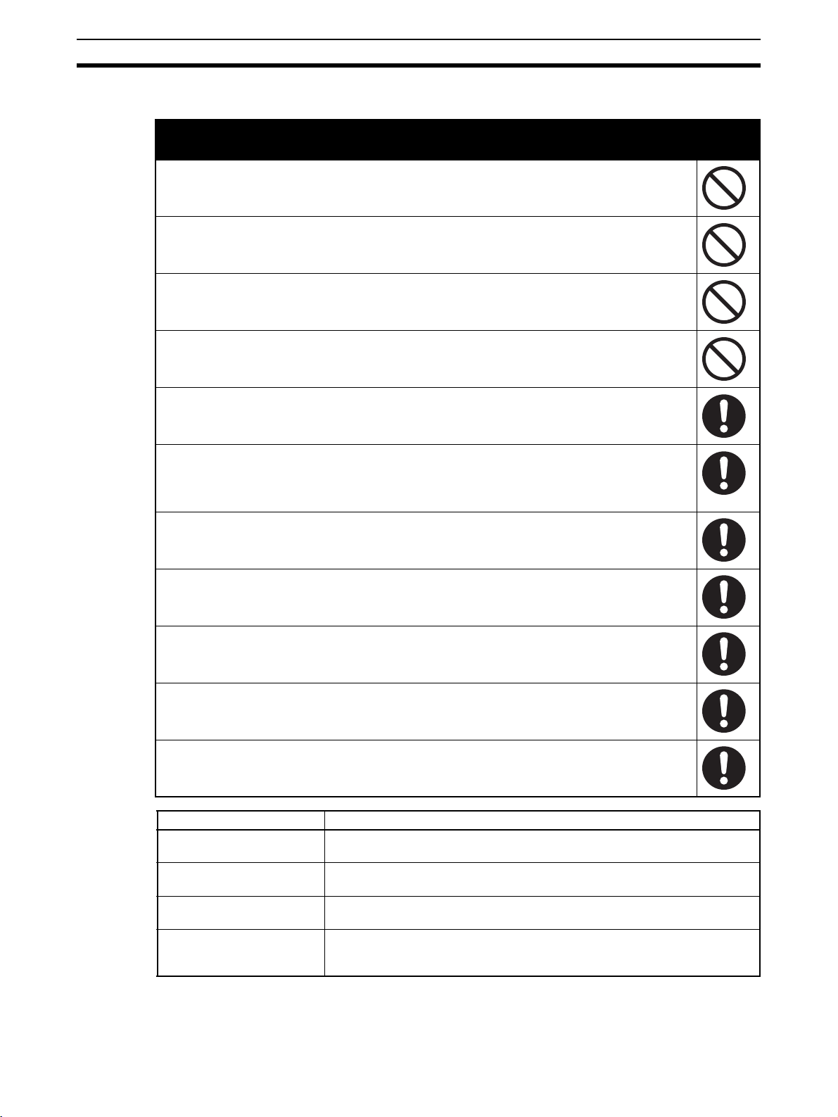
3 Safety Precautions
!WARNING
Serious injury may possibly occur due to loss of required safety functions. Do
not use the NE1A-series Controller's test outputs as safety outputs.
Serious injury may possibly occur due to loss of required safety functions. Do
not use DeviceNet standard I/O data, EtherNet/IP standard I/O data or explicit
message data as safety data.
Serious injury may possibly occur due to loss of required safety functions. Do
not use indicators or 7-segment display on the NE1A-series Controller for safety
operations.
Serious injury may possibly occur due to breakdown of safety outputs or test
outputs. Do not connect loads beyond the rated value to the safety outputs and
test outputs.
Serious injury may possibly occur due to loss of required safety functions. Wire
the NE1A-series Controller properly so that the 24-VDC line does NOT touch the
outputs accidentally or unintentionally.
Serious injury may possibly occur due to loss of required safety functions.
Ground the 0-V line of the power supply for external output devices so that the
devices do NOT turn ON when the safety output line or the test output line is
grounded.
Serious injury may possibly occur due to loss of required safety functions.
Clear previous configuration data before connecting the devices to the network.
Serious injury may possibly occur due to loss of required safety functions. Set
suitable node addresses and a suitable baud rate before connecting the devices
to the network.
Serious injury may possibly occur due to loss of required safety functions. Perform user testing and confirm that all of the device configuration data and operation is correct before starting system operation.
Serious injury may possibly occur due to loss of required safety functions.
When replacing a device, configure the replacement device suitably and confirm
that it operate correctly.
Serious injury may possibly occur due to loss of required safety functions. Use
appropriate components or devices according to the requirements given in the
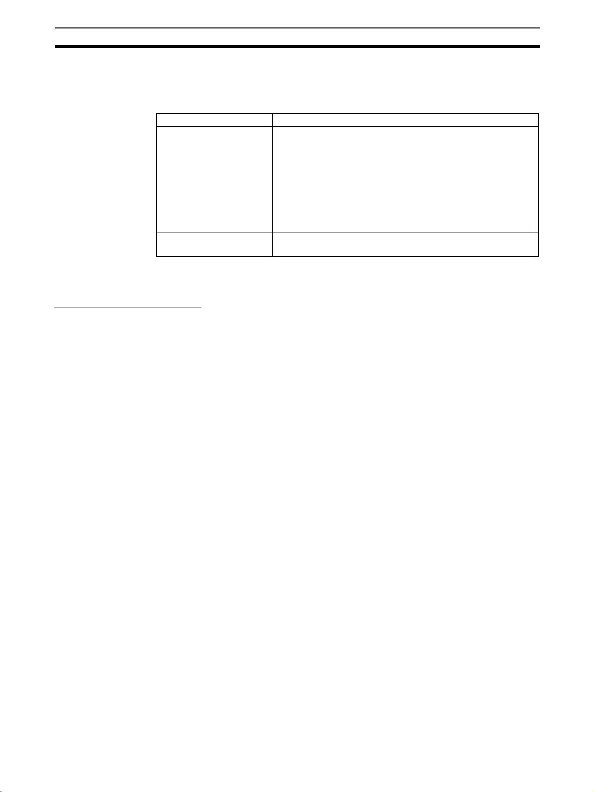
following table.
Control device Requirements
Emergency stop switch Use approved devices with a direct opening mechanism compliant with IEC/
EN 60947-5-1.
Door interlocking switch or
limit switch
Safety sensor Use approved devices compliant with the relevant product standards, regula-
Relay with forcibly guided
contacts
Use approved devices with a direct opening mechanism compliant with IEC/
EN 60947-5-1 and capable of switching micro-loads of 4 mA at 24 VDC.
tions, and rules in the country where they are used.
Use approved devices with forcibly guided contacts compliant with EN
50205. For feedback signals, use devices with contacts capable of switching
micro-loads of 4 mA at 24 VDC.
xx
Page 23

Precautions for Safe Use 4
Control device Requirements
Contactor Use contactors with a forcibly guided mechanism and monitor the auxiliary
Other devices Evaluate whether devices used are appropriate to satisfy the requirements of
NC contact to detect contactor failures. For feedback signals, use devices
with contacts capable of switching micro-loads of 4 mA at 24 VDC.
the safety category level.
4 Precautions for Safe Use
■ Handling with Care
Do not drop the NE1A-series Controller or subject it to excessive vibration or
mechanical shock. The NE1A-series Controller may be damaged and may not
function properly.
■ Installation and Storage Environment
Do not use or store the NE1A-series Controller in any of the following locations:
• Locations subject to direct sunlight
• Locations subject to temperatures or humidity outside the range specified
in the specifications
• Locations subject to condensation as the result of severe changes in temperature
• Locations subject to corrosive or flammable gases
• Locations subject to dust (especially iron dust) or salts
• Locations subject to water, oil, or chemicals
• Locations subject to shock or vibration
Take appropriate and sufficient measures when installing systems in the following locations. Inappropriate and insufficient measures may result in malfunction.
• Locations subject to static electricity or other forms of noise
• Locations subject to strong electromagnetic fields
• Locations subject to possible exposure to radioactivity
• Locations close to power supplies
■ Installation and Mounting
• Use the NE1A-series Controller within an enclosure with IP54 protection
or higher according to IEC/EN 60529.
• Use DIN rail (TH35-7.5/TH35-15 according to IEC 60715) to install the
NE1A-series Controller into the control panel. Mount the NE1A-series
Controller to the DIN rail using PFP-M End Plates (not included with the
NE1A-series Controller) to prevent it falling off the DIN rail because of
vibration.
• Space must be provided around the NE1A-series Controller, at least 5
mm from its side and at least 50 mm from its top and bottom surfaces, for
ventilation and wiring.
■ Installation and Wiring
• Use the following to wire external I/O devices to the NE1A-series Controller.
Solid wire
Stranded (flexi-
ble) wire
0.2 to 2.5 mm
0.34 to 1.5 mm
2
(AWG 24 to AWG 12)
2
(AWG 22 to AWG 16)
xxi
Page 24

Additional Precautions According to UL 1604 5
• Disconnect the NE1A-series Controller from the power supply before
starting wiring. Devices connected to the NE1A-series Controller may
operate unexpectedly.
• Properly apply the specified voltage to the NE1A-series Controller inputs.
Applying an inappropriate DC voltage or any AC voltage will cause the
NE1A-series Controller to fail.
• Be sure to separate the communications cables and I/O cables from near
high-voltage/high-current lines.
• Be cautious not to get your fingers caught when attaching connectors to
the plugs on the NE1A-series Controller.
• Tighten the DeviceNet connector screws correctly (0.25 to 0.3 N·m).
• Incorrect wiring may lead to loss of safety functions. Wire conductors correctly and verify the operation of the NE1A-series Controller before using
the system in which the NE1A-series Controller is incorporated.
• After wiring is completed, be sure to remove label for wire clipping prevention on the NE1A-series Controller to enable heat to escape or proper
cooling.
■ Power Supply Selection
Use a DC power supply satisfying the following requirements.
• The secondary circuits of the DC power supply must be isolated from the
primary circuit by double insulation or reinforced insulation.
• The DC power supply must satisfy the requirements for class 2 circuits or
limited voltage/current circuits given in UL 508.
• The output hold time must be 20 ms or longer.
■ Periodic Inspections and Maintenance
• Disconnect the NE1A-series Controller from the power supply before
replacing the Controller. Devices connected to the NE1A-series Controller
may operate unexpectedly.
• Do not disassemble, repair, or modify the NE1A-series Controller. Doing
so may lead to loss of safety functions.
■ Disposal
• Be cautions not to injure yourself when dismantling the NE1A-series Controller.
5 Additional Precautions According to UL 1604
The NE1A-series Controller is suitable for use in Class I, Div. 2, Group A, B,
C, D or Non-Hazardous Location Only.
WARNING - Explosion Hazard - Substitution of Components May Impair Suitability For Class I, Div. 2.
WARNING - Explosion Hazard - Do Not Disconnect Equipment Unless Power
Has Been Switched OFF or the Area Is Known To Be Non-Hazardous.
WARNING - Explosion Hazard - Do Not Disconnect USB Connector Unless
Power Has Been Switched OFF or the Area Is Known To Be Non-Hazardous.
xxii
Page 25
Regulations and Standards 6
6 Regulations and Standards
The following certifications have been obtained for the NE1A-SCPU01, NE1ASCPU01-V1, NE1A-SCPU02, NE1A-SCPU01-EIP, and NE1A-SCPU02-EIP.
Certifying organization Standards
TÜV Rheinland IEC 61508 part 1-7/12.98-05.00,
UL UL 1998, UL 508, UL 1604, NFPA 79, IEC 61508,
EN ISO 13849-1:2006
EN 954-1:1996 (ISO 13849-1:1999)
EN ISO 13849-2:2003,
IEC 61131-2:2007,
EN 60204-1:2006,
EN 61000-6-2:2005, EN 61000-6-4:2007,
EN ISO 13850: 2006 (EN 418:1992)
NFPA 79-2007,
ANSI RIA 15.06-1999, ANSI B11.19-2003
CSA 22.2 No. 142, CSA 22.2 No. 213
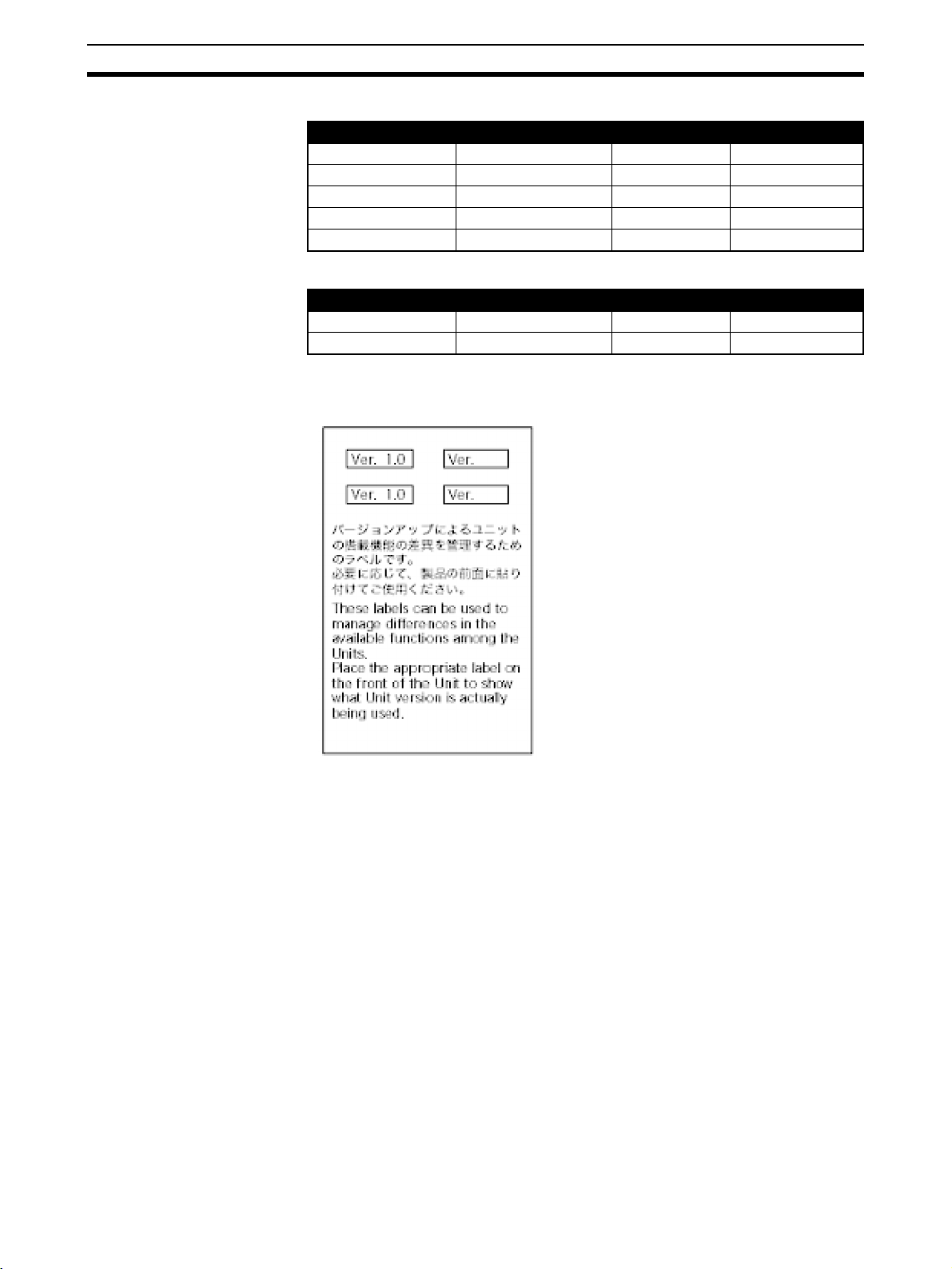
7 Unit Versions of NE1A-series Controllers
Checking the Unit Version
A “unit version” has been introduced to manage NE1A-series Safety Network
Controllers according to differences in functionality accompanying Unit
upgrades even though the model numbers are the same. The unit version can
be checked on the product itself or using the Network Configurator.
Note The Network Configurator maintains a revision number to manage device
functions for DeviceNet and EtherNet/IP. Refer to Checking the Unit Version
with the Network Configurator on page xxiv for the relationship between
NE1A-series Controller unit versions and the revisions.
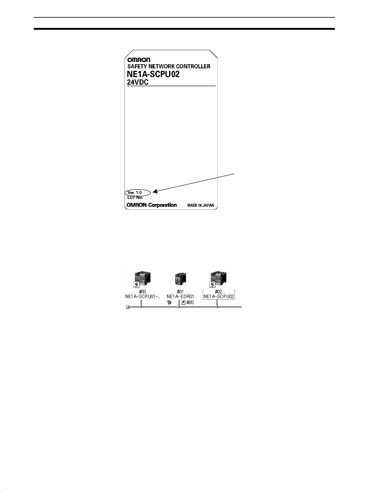
Checking the Unit Version on the Product Nameplate
The unit version (Ver. @.@) is listed near the lot number on the nameplate of
the products for which unit versions are being managed, as shown below.
• Unit versions for the NE1A-SCPU01 and NE1A-SCPU02 start at unit version 1.0.
• Controllers that do not have a unit version listed on the label are called
Pre-Ver. 1.0 Controllers.
• Unit versions for the NE1A-SCPU01-EIP and NE1A-SCPU02-EIP start at
unit version 1.0.
xxiii
Page 26
Unit Versions of NE1A-series Controllers 7
Product Nameplate
The unit version is listed here.
(Example: Ver. 1.0)
Checking the Unit Version with the Network Configurator
The following procedure can be used to check the unit version from the Network Configurator.
1,2,3... 1. Select Network - Upload to upload the configuration information. The de-
vice icons will be displayed, as shown in the following diagram.
2. Right-click on a device icon to display the popup menu shown below and
select Property from the menu.
xxiv
Page 27
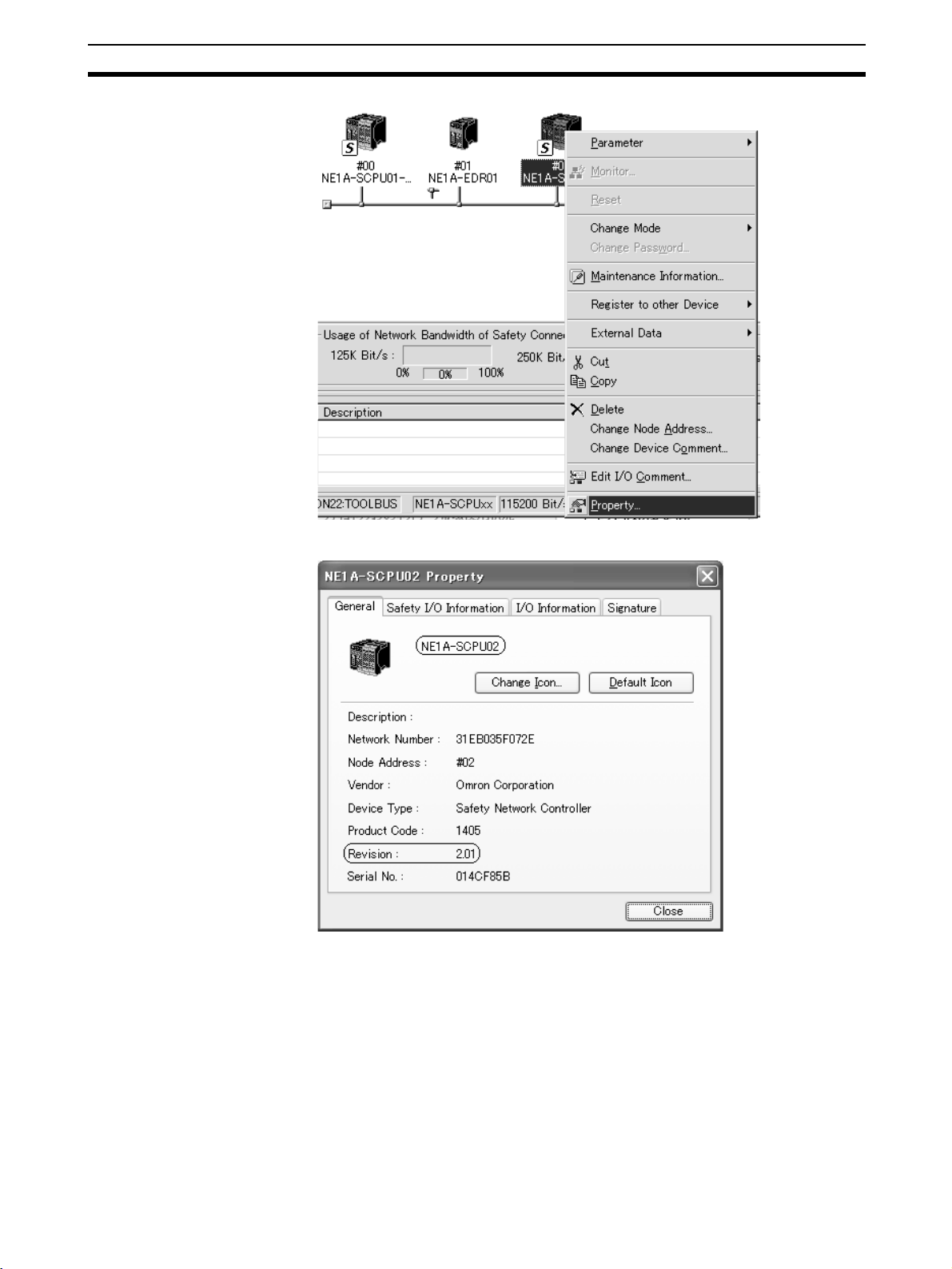
Unit Versions of NE1A-series Controllers 7
The following Property Dialog Box will be displayed.
The device name and revision are given in the Property Dialog Box. The
NE1A-series Controllers supported by Network Configurator version 2.2@ are
listed in the following table.
xxv
Page 28
Unit Versions of NE1A-series Controllers 7
■ CPU Units without EtherNet/IP
Model Device name Revision Unit version
NE1A-SCPU01 NE1A-SCPU01 1.01 Pre-Ver. 1.0
NE1A-SCPU01-V1 NE1A-SCPU01-V1 1.01 1.0
NE1A-SCPU01-V1 NE1A-SCPU01-V1 2.01 2.0
NE1A-SCPU02 NE1A-SCPU02 1.01 1.0
NE1A-SCPU02 NE1A-SCPU02 2.01 2.0
■ CPU Units with EtherNet/IP
Model Device name Revision Unit version
NE1A-SCPU01-EIP NE1A-SCPU01-EIP 1.01 1.0
NE1A-SCPU02-EIP NE1A-SCPU02-EIP 1.01 1.0
Checking the Unit Version with the Unit Version Label
The following unit version labels are provided with the Controller.
xxvi
These labels can be attached to the front of the Controllers to differentiate
between Controller with different unit versions from the front of the Controller.
Page 29

Unit Versions of NE1A-series Controllers 7
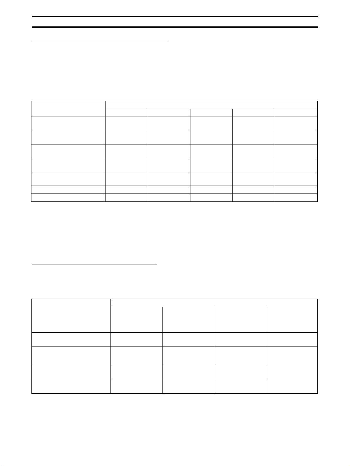
Function Support by Unit Version
Model NE1A-
Unit version
Function
Logic operations
Maximum program size
(total number of function blocks)
Added function blocks
• RS Flip-flop
• Multi Connector
•Muting
• Enable Switch
• Pulse Generator
• Counter
• Comparator
Selection of the rising edge of the reset
condition for the Reset and Restart Function Blocks
Use local I/O status in user programming --- Supported Supported Supported Supported
Use the Unit's general status in user pro-
gramming
Waiting for safety I/O communications to
start before starting program execution
I/O control functions
Contact Operation Counter --- Supported Supported Supported Supported
Total ON Time Monitor --- Supported Supported Supported Supported
DeviceNet communications functions
Number of safety I/O connections at the
Safety Master
Selection of operation of safety I/O com-
munications after a communications error
Add local output status to send data dur-
ing Slave operation.
Add local input monitoring to send data
during Slave operation.
Communications with devices on other
networks (off-link connections)
Functions supporting system startup and error recovery
Saving non-fatal error history in non-vola-
tile memory
Added function block errors to error his-
tory.
EtherNet/IP communications
I/O communications --- --- --- Supported Supported
Message communications --- --- --- Supported Supported
Routing between DeviceNet and EtherNet/IP
I/O routing --- --- --- Supported Supported
Message routing --- --- --- Supported Supported
SCPU01
Pre-Ver. 1.0 Ver. 1.0 or 2.0 Ver. 1.0 or 2.0 Ver. 1.0 Ver. 1.0
128 254 254 254 254
--- Supported Supported Supported Supported
--- Supported Supported Supported Supported
--- Supported Supported Supported Supported
--- Supported
16 32 32 32 32
--- Supported Supported Supported Supported
--- Supported Supported Supported Supported
--- Supported Supported Supported Supported
--- Supported
--- Supported Supported Supported Supported
--- Supported Supported Supported Supported
NE1A-
SCPU01-V1
(Unit version
2.0 only)
(Unit version
2.0 only)
NE1A-
SCPU02
Supported
(Unit version
2.0 only)
Supported
(Unit version
2.0 only)
NE1A-
SCPU01-EIP
Supported Supported
Supported Supported
NE1A-
SCPU02-EIP
Note In this manual, any functionality that is supported by unit version 1.0 or later or
unit version 2.0 or later is also supported by CPU Units with EtherNet/IP.
xxvii
Page 30
Unit Versions of NE1A-series Controllers 7
Unit Versions and Programming Devices
Network Configurator version 2.0@ or higher must be used when using a
NE1A-SCPU01-V1 or NE1A-SCPU02 Safety Logic Controller with unit version 2.0.
Network Configurator version 2.2@ or higher must be used when using a CPU
Unit that supports EtherNet/IP.
The following table shows the relationship between unit versions and Network
Configurator versions.
Model number Network Configurator
Ver. 1.3@ Ver. 1. 5@ Ver. 1. 6@ Ver. 2 .0@/2.1@ Ver. 2.2@
NE1A-SCPU01
Pre-Ver. 1.0
NE1A-SCPU01-V1 with unit
version 1.0
NE1A-SCPU02 with unit version 1.0
NE1A-SCPU01-V1 with unit
version 2.0
NE1A-SCPU02 with unit version 2.0
NE1A-SCPU01-EIP Cannot be used. Cannot be used. Cannot be used. Cannot be used. Can be used.
NE1A-SCPU02-EIP Cannot be used. Cannot be used. Cannot be used. Cannot be used. Can be used.
Can be used. Can be used. Can be used. Can be used. Can be used.
Cannot be used. Cannot be used. Can be used. Can be used. Can be used.
Cannot be used. Cannot be used. Can be used. Can be used. Can be used.
Cannot be used. Cannot be used. Can be used.
(See note 1.)
Cannot be used. Cannot be used. Can be used.
(See note 1.)
Can be used. Can be used.
Can be used. Can be used.
Note (1) Can be used as a Controller with unit version 1.0.
(2) Network Configurator version 1.5@ or lower can be upgraded to version
1.6@ free of charge.
(3) When using Network Configurator version 1.6@, there are no operational
differences in the NE1A-SCPU01-V1 and NE1A-SCPU02 Safety Logic
Controllers that derive from the unit version.
Unit Versions and Configuration Data
The following table shows the relationship between unit versions of NE1Aseries Controllers in Network configuration files created with Network Configurator version 2.2@ and the unit version of NE1A-series Controllers to which
configuration files are downloaded.
Unit versions of NE1A-series
CPU Unit in Network
configuration files created
with Network Configurator
version 2.2@
Pre-Ver. 1.0 CPU Unit Downloading is pos-
CPU Unit with unit version 1.0
that does not support EtherNet/IP
CPU Unit with unit version 2.0 Not possible. Not possible. Downloading is pos-
CPU Unit with unit version 1.0
that supports EtherNet/IP
Pre-Ver. 1.0 CPU
sible.
Not possible. Downloading is pos-
Not possible. Not possible. Not possible. Downloading is pos-
NE1A-series CPU Unit to which configuration file is downloaded
Unit
CPU Unit with unit
version 1.0 that
does not support
EtherNet/IP
Not possible.
(See note 1.)
sible.
CPU Unit with unit
version 2.0
Not possible.
(See note 1.)
Downloading is possible. (See note 2.)
sible.
CPU Unit with unit
version 1.0 that
supports EtherNet/
IP
Not possible.
(See note 1.)
Not possible.
(See note 1.)
Not possible.
(See note 1.)
sible.
xxviii
Note (1) Downloading is possible if the device type is changed using the function
provided in Network Configurator version 2.2@. For details, refer to
NE1A-series Controller Upgrade Procedure on page xxix.
(2) Only functions CPU Units with unit version 1.0 can be used.
Page 31

Unit Versions of NE1A-series Controllers 7
IMPORTANT The Configuration data created with unit version 1.0 can be downloaded to a
NE1A-series Controller with unit version 2.0. The data will be subsequently
treated as unit version 2.0 data if it is uploaded.
NE1A-series Controller Upgrade Procedure
Functions are added and functionality is expanded in various ways for the
NE1A-series Controllers. The device type in an existing network configuration
file can be changed to a higher version so that the new functionality can be
used.
The following table shows the NE1A-series Control device types in network
configuration files and the device types that they can be upgraded to.
Device type before
change
NE1A-SCPU01
Pre-Ver. 1.0
NE1A-SCPU01-V1
Unit Ver. 1.0
NE1A-SCPU02
Unit Ver. 1.0
NE1A-SCPU01-V1
Unit Ver. 2.0
NE1A-SCPU02
Unit Ver. 2.0
NE1A-SCPU01-EIP
Unit Ver. 1.0
NE1A-SCPU02-EIP
Unit Ver. 1.0
Device type after change
NE1A-SCPU01-V1 NE1A-SCPU02 NE1A-
SCPU01-EIP
Un it Ve r. 1.0 Un it Ve r. 2.0 Unit Ver. 1.0 Un it Ver. 2.0 Un it Ve r. 1.0 Un it Ve r. 1. 0
OK OK OK OK OK OK
--- OKOKOKOKOK
Not possible Not possible --- OK Not possible OK
Not possible --- Not possible OK OK OK
Not possible Not possible Not possible --- Not possible OK
Not possible Not possible Not possible Not possible --- OK
Not possible Not possible Not possible Not possible Not possible ---
NE1A-
SCPU02-EIP
1. Reading Configuration Data
Use the following procedure to read the configuration data with the Network
Configurator.
• Read the saved configuration data.
• Use network uploading to read configuration data from devices on the
network.
The following screen will be displayed when reading has been completed.
2. Converting Configuration Data
In the data read with the Network Configurator, right-click the NE1A-SCPU01
that is to be changed to the NE1A-SCPU01-V1 or NE1A-SCPU02 and select
Change Device Type from the pop-up menu.
xxix
Page 32

Unit Versions of NE1A-series Controllers 7
Next, select the new device in the New Device and press the OK Button.
After a moment, the model number will change and the configuration data for
the new device will be completed.
3. Expansion Configuration
When the data configuration is converted, all expanded functionality will be
set to the default values. Set the configuration for all expanded functionality to
be used.
xxx
IMPORTANT (1) When changing the device type using Network Configurator version 1.61,
open the Edit Device Parameters Dialog Box of the Controller, select a
connection on the Safety Connection Tab Page, and click the Update But-
ton.
Page 33

Unit Versions of NE1A-series Controllers 7
(2) When changing the device type using Network Configurator version 2.@
or higher, the connection information will be updated automatically.
xxxi
Page 34

Page 35

SECTION 1
Overview of the NE1A-series Safety Network Controllers
1-1 About NE1A-series Safety Network Controllers . . . . . . . . . . . . . . . . . . . . . . 2
1-1-1 Introduction to the NE1A-series Safety Network Controllers . . . . . 2
1-1-2 Features of the NE1A-series Controllers . . . . . . . . . . . . . . . . . . . . . 3
1-1-3 Functional Overview. . . . . . . . . . . . . . . . . . . . . . . . . . . . . . . . . . . . . 4
1-1-4 Functions Improved in the Unit Version 2.0 Upgrade . . . . . . . . . . . 6
1-1-5 Functions Added for Controllers that Support EtherNet/IP . . . . . . . 6
1-1-6 Comparison of the I/O Capacity of the NE1A-SCPU01(-V1)(-EIP) and
NE1A-SCPU02(-EIP). . . . . . . . . . . . . . . . . . . . . . . . . . . . . . . . . . . . 6
1-2 System Configuration . . . . . . . . . . . . . . . . . . . . . . . . . . . . . . . . . . . . . . . . . . . 7
1-2-1 DeviceNet Safety System Overview. . . . . . . . . . . . . . . . . . . . . . . . . 7
1-2-2 Example System Configurations . . . . . . . . . . . . . . . . . . . . . . . . . . . 8
1-3 System Setup Procedure . . . . . . . . . . . . . . . . . . . . . . . . . . . . . . . . . . . . . . . . . 17
1
Page 36

About NE1A-series Safety Network Controllers Section 1-1
1-1 About NE1A-series Safety Network Controllers
1-1-1 Introduction to the NE1A-series Safety Network Controllers
The NE1A-series Safety Network Controllers provide various functions, such
as safety logic operations, safety I/O control, and a DeviceNet Safety protocol.
The NE1A-series Controller allows the user to construct a safety control/network system that meets the requirements for Safety Integrity Level (SIL) 3
according to IEC 61508 (Functional Safety of Electrical/Electronic/ Programmable Electronic Safety-related Systems) and the requirements for Safety
Category 4 according to EN 954-1.
In the example system shown below, the safety control system implemented
with an NE1A-series Controller and the monitoring system implemented with
a Standard PLC are realized on the same network.
• As a Safety Logic Controller, the NE1A-series Controller executes safety
logic operations and controls local I/O.
• As a DeviceNet Safety Master, the NE1A-series Controller controls the
remote I/O of DeviceNet Safety Slaves.
• As a DeviceNet Standard Slave, the NE1A-series Controller communicates with the DeviceNet Standard Master.
Safety Logic Operations and
Safety I/O Control
Standard PLC
Standard Master
Non-safety-related Control
(Standard Control)
Standard Slave
Network Configurator
NE1A
Safety Master
Standard Slave
DST1 series
Safety Slave
Safety related Control
The PLC system monitors the
NE1A (i.e., the safety control
system) using DeviceNet I/O
communications and explicit
messages.
The DeviceNet Safety
System controls remote I/O.
2
Page 37

About NE1A-series Safety Network Controllers Section 1-1
1-1-2 Features of the NE1A-series Controllers
Safety Logic Operations
In addition to basic logic functions, such as AND and OR, function blocks such
as Emergency Stop or Safety Gate Monitoring that enable various safety
applications are supported.
Local Safety I/O
• In the NE1A-SCPU01(-V1)(-EIP), a total of 24 local safety I/O points are
supported: 16 inputs and 8 outputs.
• In the NE1A-SCPU02(-EIP), a total of 48 local safety I/O points are supported: 40 inputs and 8 outputs.
• Faults in external wiring can be detected.
• Dual Channel Mode can be set for pairs of related local input terminals.
When Dual Channel Mode is set, an NE1A-series Controller can evaluate
the input data patterns and the time discrepancy between input signals.
• Dual Channel Mode can be set for pairs of related local output terminals.
When Dual Channel Mode is set, an NE1A-series Controller can evaluate
the output data patterns.
DeviceNet Safety Communications
• As a Safety Master, Pre-Ver. 1.0 Controllers can perform safety I/O communications with up to 16 connections using up to 16 bytes per connection.
• As a Safety Master, an NE1A-series Controller with unit version 1.0 or
later (including Controllers that support EtherNet/IP) can perform safety
I/O communications with up to 32 connections using up to 16 bytes per
connection.
• As a Safety Slave, the NE1A-series Controllers can perform safety I/O
communications with a maximum of four connections using up to 16 bytes
per connection.
DeviceNet Standard Communications
As a Standard Slave, the NE1A-series Controllers can perform standard I/O
communications with one Standard Master for up to two connections using up
to 16 bytes per connection.
EtherNet/IP Standard Communications (Only Controllers that Support EtherNet/IP)
As an EtherNet/IP target, an NE1A-series Controller can perform standard I/O
communications with up to two connections with a single EtherNet/IP originator, using up to 128 bytes for input and 16 bytes for output per connection.
DeviceNet Communications Disable (Standalone) Setting
An NE1A-series Controller can be used as a Standalone Controller by disabling its DeviceNet communications.
Configuration with a Graphical Tool
• A graphical tool is provided for both network configuration and user programming. It enables easy configuration and programming.
• A Logic Editor can be activated from the Network Configurator.
• Configuration data can be downloaded and uploaded, and devices can be
monitored online via DeviceNet, USB, EtherNet/IP, or the peripheral interface of an OMRON PLC.
3
Page 38

About NE1A-series Safety Network Controllers Section 1-1
System Startup and Error Recovery Support
• The error information can be checked by using the Network Configurator
or the indicators on the front of the NE1A-series Controller.
• The NE1A-series Controller’s internal status information can be monitored from a Standard PLC by allocating the information in the Standard
Master. In the same way, monitoring with a Safety PLC is possible by allocating information in the Safety Master.
• An NE1A-series Controller's internal status information can be allocated
in an EtherNet/IP originator and monitored by a Standard PLC. (Possible
only for Controllers that support EtherNet/IP.)
Access Control with a Password
• The NE1A-series Controller’s configuration data is protected by a password set in the Controller.
• The Network Configurator controls access to each project file with a password.
1-1-3 Functional Overview
Function Overview Details
Logic Operations
Logic operations Basic logic operations, such as AND and OR, and function blocks,
Safety I/O
I/O comments The user can store any name for each I/O terminal using a maximum
I/O power monitoring The NE1A-series Controllers can detect whether I/O power is
Safety inputs The NE1A-SCPU01(-V1)(-EIP) supports a 16 safety inputs.
Input circuit diagnosis Test pulses are used to check the NE1A-series Controller’s internal
Input ON/OFF delays Input time constants between 0 and 126 ms in multiples of the
Dual Channel Mode Time discrepancies in changes in data or input signals between two
Test pulse outputs The NE1A-SCPU01(-V1)(-EIP) supports four independent test out-
Current monitoring for
muting lamp (T3, T7 terminal only)
Overcurrent detection/protection
such as Emergency Stop (ESTOP) and Safety Gate Monitoring
(SGATE), are supported.
In the Pre-Ver. 1.0 Controllers, up to 128 logic functions and function
blocks can be used in programming.
In the Controllers with unit version 1.0 or later (including Controllers
that support EtherNet/IP), up to 254 logic functions and function
blocks can be used in programming.
of 32 characters (ASCII).
supplied within the normal voltage range.
The NE1A-SCPU02(-EIP) supports a 40 safety inputs.
circuits, external devices, and external wiring.
Controller’s cycle time can be set for Controller’s inputs.
Setting input ON/OFF delays helps reduce influence from chattering
or external noise.
paired local inputs can be evaluated.
puts.
The NE1A-SCPU02(-EIP) supports eight independent test outputs.
These are normally used in combination with safety inputs.
They can also be set for use as signal output terminals.
The NE1A-SCPU01(-V1)(-EIP) can detect a disconnection at the T3
terminal.
The NE1A-SCPU02(-EIP) can detect disconnections at the T3 and
T7 terminals.
An output is blocked when an overcurrent is detected to protect the
circuit.
SECTION 8
7-1-1
7-1-2
7-2
7-3
4
Page 39

About NE1A-series Safety Network Controllers Section 1-1
Function Overview Details
Safety outputs The NE1A-SCPU01(-V1)(-EIP) and NE1A-SCPU02(-EIP) both sup-
Output circuit diagnosis Test pulses are used to check the NE1A-series Controller’s internal
Overcurrent detection/protection
Dual Channel Mode Both of two paired outputs can be set into a safety state when an
DeviceNet Communications
Safety Master A master-slave relationship is established for each connection on the
Safety Slave An NE1A-series Controller can also operate as a DeviceNet Safety
Safety I/O communications
operating mode for communications errors
Standard Slave An NE1A-series Controller can also operate as a Standard Slave,
Explicit messages Explicit messages can be used to read an NE1A-series Controller’s
Automatic baud rate detection
DeviceNet Communications Disable (Standalone)
DeviceNet communications
disable (Standalone) setting
System Startup/Error Recovery Functions
Error history Errors detected by the NE1A-series Controller are recorded along
Online monitoring The NE1A-series Controller’s internal status information and I/O data
Other Functions
Configuration lock The configuration data stored in the NE1A-series Controller can be
Reset The NE1A-series Controller can be reset from the Network Configu-
Password A password can be set to prevent unintended or unauthorized
port eight safety outputs.
circuits, external devices, and external wiring.
To protect the circuit, the output is cut off when an overcurrent is
detected.
error occurs in either of the two paired local outputs without depending on the user program.
DeviceNet Safety Network separate from the Master-Slave communications on the DeviceNet Standard Network. This enables the
NE1A-series Controller to be the safety master to control the connections.
Slave, and the Controller’s internal status information as well as a
specified area of I/O can be allocated in the Safety Master.
The operating mode to use for safety I/O communications when a
communications error occurs can be selected.
• Automatic recovery (previous function).
• Stop only the connection where the error occurred.
• Stop all connections.
and the Controller’s internal status information as well as a specified
area of I/O can be allocated in the Standard Master.
status information. In addition, explicit messages set from the
Network Configurator can be sent from the user program.
The NE1A-series Controller’s baud rate can be set automatically to
match the baud rate of the network master.
An NE1A-series Controller can be used as a Standalone Controller
by disabling the Controller’s DeviceNet communications.
with the Controller’s total operating time at the point that the error
was detected.
can be monitored online from the Network Configurator.
locked to protect the data after it has been downloaded and verified.
rator.
access to the NE1A-series Controller.
7-4
4-4
4-5
4-4
4-6
SECTION 6
4-1-1
4-1-2
12-4
System Configuration Manual,
Section 7
9-1
9-2
9-3
5
Page 40

About NE1A-series Safety Network Controllers Section 1-1
1-1-4 Functions Improved in the Unit Version 2.0 Upgrade
The following table outlines the changes made in the unit version 2.0 upgrade.
Function Summary Reference
Logic operations
Program execution delay This function enables waiting for safety I/O communications to start
before executing the program. Even if this function is used, however, program execution may start before safety I/O communications and logic
errors may occur for function blocks under some circumstances. This
function can be enable to prevent certain logic errors.
10-1-6
1-1-5 Functions Added for Controllers that Support EtherNet/IP
For Controllers that support EtherNet/IP, the following functions have been
added to those of the NE1A-SCPU01(-V1) and NE1A-SCPU02.
Function Overview Details
EtherNet/IP Communications (Tag Data Link) Functions
I/O communications The Controller can perform I/O communications as an EtherNet/IP target.
Not only specified I/O areas but NE1A-series Controller internal status
information and DeviceNet Safety I/O connection information can be allocated in the originator.
Explicit message communications
Routing between DeviceNet and EtherNet/IP
I/O routing DeviceNet Safety I/O connection information can be routed to an Ether-
Message routing Explicit message can be routed between DeviceNet and EtherNet/IP. SECTION 5
NE1A-series Controller status information can be read by services using
explicit message communications.
Net/IP I/O connection.
SECTION 5
SECTION 6
SECTION 5
1-1-6 Comparison of the I/O Capacity of the NE1A-SCPU01(-V1)(-EIP)
and NE1A-SCPU02(-EIP)
Item NE1A-SCPU(-V1)(-EIP) NE1A-SCPU02(-V1)(-EIP) Details
Number of I/O points
Safety inputs 16 40 2-1
Test outputs 4 8 2-1
Safety outputs 8 8 2-1
6
Page 41

System Configuration Section 1-2
1-2 System Configuration
1-2-1 DeviceNet Safety System Overview
DeviceNet is an open-field, multi-vendor, multi-bit network, which combines
the controls in the machine and line control levels with information. The
DeviceNet Safety network adds safety functions to the conventional
DeviceNet standard communications protocol. The DeviceNet Safety concept
has been approved by a third-party organization (TÜV Rhineland).
Just as with DeviceNet, DeviceNet Safety-compliant devices from third-party
vendors can be connected to a DeviceNet Safety network. Also, DeviceNetcompliant devices and DeviceNet Safety-compliant devices can be combined
and connected on the same network.
By combining DeviceNet Safety-compliant products, a user can construct a
safety control/network system that meets the requirements for Safety Integrity
Level (SIL) 3 according to IEC 61508 (Functional Safety of Electrical/Electronic/Programmable Electronic Safety-related Systems) and the requirements for Safety Category 4 according to EN 954-1.
Safety Control as a Safety Network
Controller
Safety I/O Communications
-
Safety Network Controller
-
Safety Master
-
Standard Slave
Safety
communications
Safety Terminal
-
Safety Slave
-
Standard Slave
Network Configurator
Safety
configuration
Safety Network Controller
-
Safety Slave
-
Standard Slave
Standard
configuration
Standard
communications
Standard Control and Monitoring as
a Standard PLC
Standard I/O communications
Explicit message communications
-
Standard PLC/Standard Master
Standard Slave
7
Page 42

System Configuration Section 1-2
)
1-2-2 Example System Configurations
The following examples illustrate safety control systems using NE1A-series
Controllers.
• Safety Control System with an NE1A-series Safety Master
• System Combining an NE1A-series Safety Control System and a Standard PLC Monitoring Control System
• System Combining a Distributed Safety Control System with Multiple
NE1A-series Controllers and a Centralized Monitoring System Using
Standard PLCs
• Standalone NE1A-series Controller System
• Connection with a Network Configurator
Safety Control System with an NE1A-series Safety Master
This system uses the NE1A-series Controller as a Safety Master and establishes a Safety Remote I/O System with Safety Slaves.
The Pre-Ver. 1.0 Controllers can perform safety I/O communications as a
Safety Master for a maximum of 16 connections (16 Slaves) with up to 16
bytes per connection.
Controllers with unit version 1.0 or later (including Controllers that support
EtherNet/IP) can perform safety I/O communications as a Safety Master for a
maximum of 32 connections (32 Slaves) with up to 16 bytes per connection.
The NE1A-series Controllers support two protocols, single cast and multicast
(broadcast), for safety I/O connections.
NE1A
Safety Master
DST1 Safety Slave
Safety connections (logic communications paths)
Either single-cast or multicast
16 connections maximum
32 connections maximum (unit version 1.0 or later
Safety Slave by other
manufacturer
Safety Slave by other
manufacturer
8
Page 43
System Configuration Section 1-2
System Combining a Safety Control System and a PLC Monitoring Control System
This system uses the NE1A-series Controller as a Safety Master and establishes a Safety Remote I/O System with Safety Slaves.
The NE1A-series Controller is used as a Standard Slave and standard I/O
communications are performed with the Standard Master. The NE1A-series
Controller simultaneously functions as the Safety Master and a Standard
Slave.
As a Standard Slave, the NE1A-series Controller enables standard I/O communications for a maximum of two connections with up to 16 bytes per connection. Four protocols (i.e., Poll, Bitstrobe, COS and Cyclic) are supported
for I/O connections. The NE1A-series Controller cannot operate as a Standard Master.
The Safety Control System can be monitored using a Standard PLC by allocating the NE1A-series Controller’s status information (general status, local
I/O error status, or other information) or logic operation results in the Standard
PLC for standard I/O communications.
A Safety System and a Monitoring System can be combined and established
on the same network by using standard devices and safety devices.
Safety Control SystemMonitoring System
Safety Slaves by other manufacturers
Standard PLC
Standard Master
Standard I/O communications
and explicit messages
NE1A
Safety Master
Standard Slave
Safety I/O communications
DST1 Safety Slave
IMPORTANT The data attributes handled by standard I/O communications and explicit
message communications are non-safety data. The necessary measures for
safety data are not taken for this data during data generation. Therefore, do
not use this data to configure the Safety Control System.
A maximum total of 64 standard nodes and safety nodes can be connected on
the same DeviceNet network.
9
Page 44

System Configuration Section 1-2
System Combining a Distributed Safety Control System with Multiple NE1A-series
Controllers and a Centralized Monitoring System
This system uses each NE1A-series Controller as a Safety Master and establishes a Safety Remote I/O System with Safety Slaves.
Each NE1A-series Controller also simultaneously functions as a Standard
Slave and standard I/O communications are performed with the Standard
Master.
The Safety Control System can be monitored using a Standard PLC by allocating the NE1A-series Controller’s status information (general status, local
I/O error status, or other information) or logic operation results in the Standard
PLC.
In the DeviceNet Safety System, multiple Safety Masters can be connected
on the same network. Therefore, the distributed safety control blocks can be
monitored centrally on the same network.
Monitoring System
Standard PLC
Standard Master
Standard I/O
communications or
explicit messages
NE1A #1
Safety Master
Standard Slave
NE1A #2
Safety Master
Standard Slave
DST1 Safety Slave
Safety Control System A
Safety I/O communications
Safety Slaves by other manufacturers
Safety I/O communications
10
Safety Control System B
DST1 Safety Slave
Safety Slaves by other manufacturers
Page 45

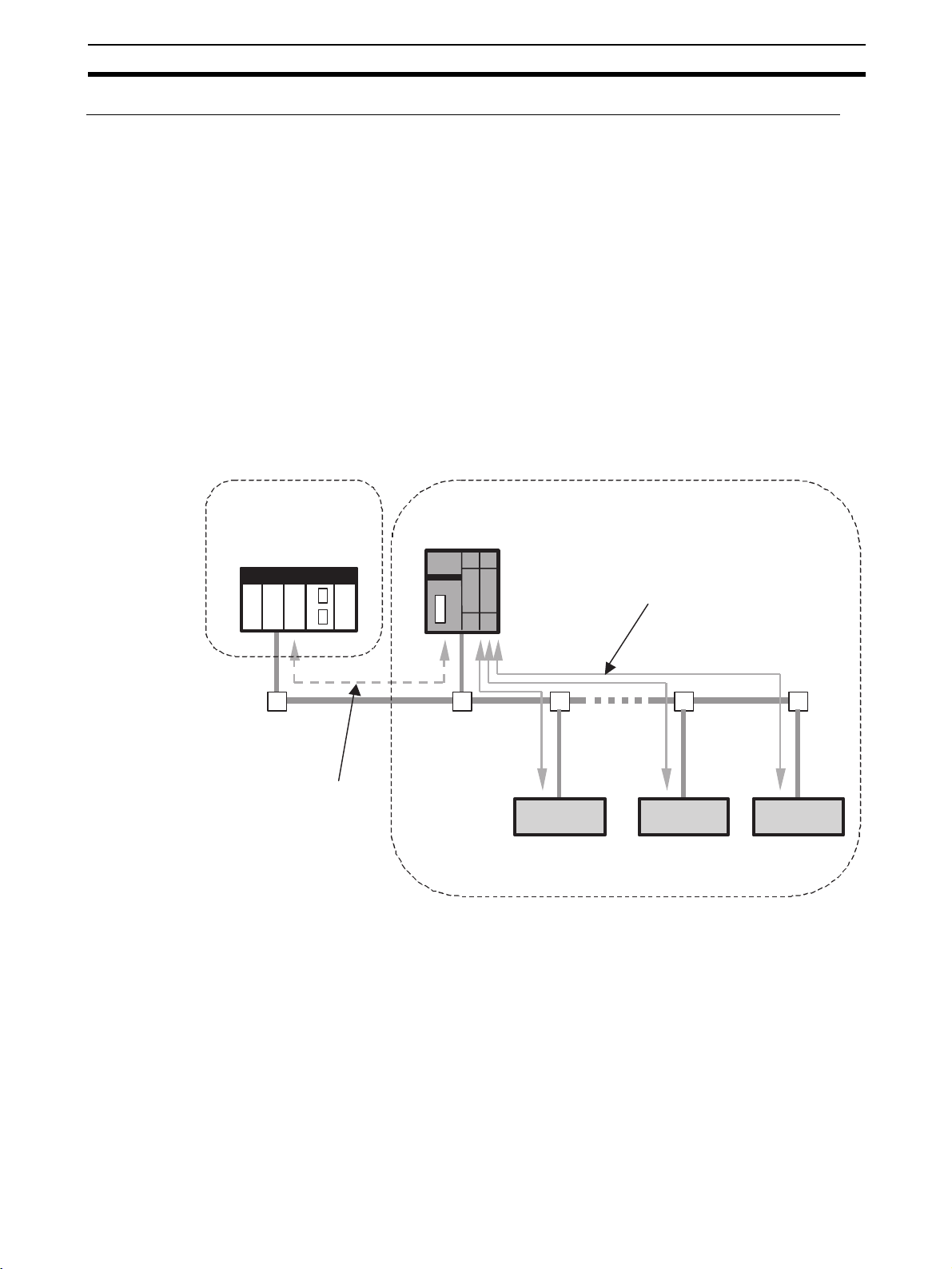
System Configuration Section 1-2
Also, safety I/O communications between NE1A-series Controllers can be
performed as illustrated in the following diagram. In the diagram, NE1A #2 is
set as the slave of NE1A #1 safety connections to perform safety I/O communications.
The NE1A-series Controller functions as a Safety Master, Safety Slave, and
Standard Slave simultaneously. As a Safety Slave, the NE1A-series Controller
enables safety I/O communications for a maximum of four connections with up
to 16 bytes per connection.
Monitoring System
Standard PLC
Standard Master
NE1A #1
Safety Master
Standard Slave
NE1A #2
Safety Master
Safety Slave
Standard Slave
NE1A #1 functions as the Safety Master
for NE1A #2.
DST1 Safety Slave
Safety Control System A
Safety Slaves by other manufacturers
Safety I/O communications
Safety Control System B
DST1 Safety Slave
NE1A #2 functions as a Safety Slave
under NE1A #1.
Safety Slaves by other manufacturers
IMPORTANT The data attributes handled by DeviceNet standard I/O communications and
explicit message communications are non-safety data. The necessary measures for safety data are not taken for this data during data generation. Therefore, do not use this data to configure the Safety Control System.
11
Page 46

System Configuration Section 1-2
y
Monitoring DeviceNet or DeviceNet Safety Systems via Ethernet from Controller Made
by Other Manufacturers
If the networks are constructed using an NE1A-EDR01 EtherNet/IPDeviceNet Router, devices on DeviceNet or DeviceNet Safety network can be
accessed from general-purpose controllers (e.g., PLCs or computers) in an
Ethernet network using the UDP service. This enables monitoring a
DeviceNet or DeviceNet Safety control system via Ethernet from a machine
controller or monitor computer that does not support a DeviceNet interface.
This can be used to easily add a DeviceNet Safety control system to an existing system.
Safety controls can be monitored by accessing
devices on the DeviceNet Safety network using the
UDP service from a general-purpose controller on
the Ethernet network (e.g., a PLC or computer).
PLC (OMRON or other maker)
OR
Computer
ED Router
(NE1A-EDR01)
Ethernet
Command via UDP
DeviceNet Safety
Socket service (UDP)
Command via UDP
DeviceNet Safety
DST1-series Slaves
NE1A Safety Network Controller
DeviceNet Safety
DeviceNet Safety
DST1-series Slaves
Note Refer to the EtherNet/IP-DeviceNet Router Operation Manual (Cat. No. Z912)
for details on the NE1A-EDR01 EtherNet/IP-DeviceNet Router.
Monitoring a DeviceNet Safety (or DeviceNet) System from a PLC or Controller on an
EtherNet/IP Network
As shown in the following diagram, a DeviceNet Safety (or DeviceNet) system
can be monitored using EtherNet/IP Standard Target I/O from a PLC or Controller on an EtherNet/IP network via an NE1A-series Controller that supports
EtherNet/IP.
Devices on a DeviceNet Safety network can be
accessed from a general-purpose Controller (such as a
PLC or personal computer) on Ethernet, and safety
control can be monitored.
OMRON PLC or PLC from another maker
or
Personal computer
12
Ethernet
NE1A-series Controller
(supporting EtherNet/IP)
DeviceNet Safety
DST1-series
DeviceNet Safety Slaves
NE1A-series Controller
(supporting EtherNet/IP)
DeviceNet Safety
DST1-series
DeviceNet Safet
Slaves
Page 47

System Configuration Section 1-2
NE1A-series Controller DeviceNet Communications Disable (Standalone) Setting
When only a few I/O points are required for safety control, the NE1A-series
Controller's DeviceNet communications can be disabled so that it can be used
as a Standalone Controller.
Use the Network Configurator to disable the DeviceNet communications
(standalone).
Emergency stop
buttons
Network Configurator
USB communications
Door switches
NE1A
(Standalone)
Contactors
Two-hand switches
IMPORTANT Use a USB port connection to disable the DeviceNet communications (stan-
dalone). With Controllers that support EtherNet/IP, either the USB port or EtherNet/IP can be used. DeviceNet communications are stopped after
DeviceNet communications are disabled (standalone), so the setting cannot
be made from the DeviceNet port.
13
Page 48

System Configuration Section 1-2
Connection with Network Configurator
The NE1A-series Controller is set and programmed using a Network Configurator. The Network Configurator also enables uploading configuration data,
online monitoring of program execution status, error history checks, etc.
The Network Configurator can be used in the following ways:
• Direct connection to DeviceNet
• USB connection to the NE1A-series Controller
• Serial connection to an OMRON PLC
• Connection from Ethernet using an EtherNet/IP-DeviceNet Router
• Direct connection to EtherNet/IP (for Controllers that support EtherNet/IP)
Direct Connection to DeviceNet
A DeviceNet Board/Card enables the Network Configurator to connect directly
to the network. Remote configuration and monitoring are supported for standard nodes and safety nodes on the network. When connected directly to
DeviceNet, the Network Configurator forms one node on the network.
Network Configurator
NE1A
Standard PLC
Standard Master
PCI Board
PCMCIA Card
Downloading/uploading configuration
data and monitoring are supported from
the Network Configurator for devices on
the network via DeviceNet.
Explicit message communications
Safety Slave
Standard Slave
14
Page 49

System Configuration Section 1-2
y
USB Connection to an NE1A-series Controller
The Network Configurator can be used by connecting to the USB port on the
NE1A-series Controller. Remote configuration and monitoring are supported
for not only the Controller connected to the USB port but also for other
devices on the network. For a USB connection, the Network Configurator
does not use a node address on the network.
Network Configurator
NE1A
Standard PLC
Standard Master
USB communications
Serial Connection to an OMRON PLC
The Network Configurator can be used by connecting to a serial port on an
OMRON PLC. Remote configuration and monitoring are supported for standard nodes and safety nodes on the network. For a PLC connection, the Network Configurator does not use a node address on the network.
NE1A
Explicit message communications
Explicit message communications
Safety Slave
Standard PLC
Standard Master
Standard Slave
Serial communications
(Host Link or Peripheral
bus (toolbus))
Network Configurator
Safet
Slave Standard Slave
Note Check the following when downloading from a Standard Master to the NE1A.
• The timeout monitor time for the Standard Master must be at least
15 seconds.
• Remote I/O communications from the Standard Master to the NE1A must
be stopped (disconnected).
15
Page 50

System Configuration Section 1-2
r
y
Connecting via an EtherNet/IP-DeviceNet Router
If the networks are built using an NE1A-EDR0 EtherNet/IP-DeviceNet Router,
a Network Configurator connected at any point can be used to access the
NE1A Safety Network Controllers through the EtherNet/IP-DeviceNet Router.
The Network Configurator can be at any of the following locations.
• Connected via to a USB port on a Safety Network Controller on a different
DeviceNet Safety network (See note 1.)
• Connected to an EtherNet/IP network
• Connected to a different DeviceNet Safety network
NE1A Safety Network Controllers can be accessed through the
EtherNet/IP-DeviceNet Router from a Network Configurator at
any of the following locations.
1) Connected via to a USB port on a Safety Network Controller
on a different DeviceNet Safety network
2) Connected to an EtherNet/IP network
3) Connected to a different DeviceNet Safety network
Ethernet (EtherNet/IP)
2) Network Configurator
ED Router
(NE1A-EDR01)
USB
DeviceNet Safety
1) Network Configurator
DeviceNet Safety
DST1-series Slaves
NE1A Safety
Network Controller
DeviceNet Safety
Note (1) The NE1A-SCPU01-V1 with unit version 2.0 or later (including Control-
lers that support EtherNet/IP) or NE1A-SCPU02 with unit version 2.0 or
later (including Controllers that support EtherNet/IP) is required. NE1A
Safety Network Controllers cannot be accessed through a EtherNet/IPDeviceNet Router from a Network Configurator connected to the USB
port on the NE1A-SCPU01-V1 with unit version 1.0, or the NE1ASCPU02 with unit version 1.0 or earlier.
(2) Refer to the EtherNet/IP-DeviceNet Router Operation Manual (Cat. No.
Z912) for details on the NE1A-EDR01 EtherNet/IP-DeviceNet Router.
Direct Connection to EtherNet/IP (for Controllers that Support EtherNet/IP)
Remote configuration and monitoring are enabled for standard and safety
devices on both EtherNet/IP and DeviceNet networks.
Remote configuration and monitoring are enabled for standard
and safety devices on both EtherNet/IP and DeviceNet
networks, using the Network Configurator.
DeviceNet Safety
DST1-series Slaves
3) Network Configurato
16
Network Configurator
NE1A-series Controller
(supporting EtherNet/IP)
DeviceNet
EtherNet/IP
NE1A-series Controller
(supporting EtherNet/IP)
DeviceNet Safety
DST1-series
DeviceNet Safet
Slaves
Page 51

System Setup Procedure Section 1-3
1-3 System Setup Procedure
The general working phases until the Safety System is operational are shown
below.
1. System Design
3. Installation and Wiring
2. Programming
4. Configuration
5. User Testing
6. System Operation
The NE1A-series Controller information required in each phase is described
in the following sections.
Working phase Required information Details
System design • System overview and example configurations
• Specifications and functions
• Performance
Programming • Programming guidelines
• Function block specifications
Installation and wiring • Node address and baud rate settings
• Installation location
• Device connections
• Power supply wiring
• Connection with I/O devices
• Wiring for DeviceNet
• EtherNet/IP wiring
Configuration • Configuration method Section 9
User test • Error classification and error history Section 12
System operation • Maintenance and inspection Section 13
Section 1
Section 2, Section 4 to 10
Section 11
Section 8
Section 4-1
Section 3
Refer to the following manuals for information on DeviceNet and EtherNet/IP
installation, DeviceNet Safety System construction, Network Configurator
operation, Programming Device operation, and other devices used in the
safety system.
Item Manual name Cat. No.
Installation of DeviceNet DeviceNet User’s Manual W379
Installation of EtherNet/IP NE1A-series DeviceNet Safety Network Control-
ler Operation Manual
Z906-E1-07
or higher
17
Page 52

System Setup Procedure Section 1-3
Item Manual name Cat. No.
Construction of a DeviceNet
Safety System
Network Configurator Operation (WS02-CFSC1-E)
Programming Device Operation
Installation of Safety I/O Terminals
DeviceNet Safety System Configuration Manual Z905
DeviceNet Safety I/O Terminal Operation Manual
Z904
18
Page 53

Specifications and Nomenclature
2-1 Nomenclature and Functions . . . . . . . . . . . . . . . . . . . . . . . . . . . . . . . . . . . . . 20
2-1-1 Nomenclature . . . . . . . . . . . . . . . . . . . . . . . . . . . . . . . . . . . . . . . . . . 20
2-1-2 Indicator/Display Areas . . . . . . . . . . . . . . . . . . . . . . . . . . . . . . . . . . 24
2-1-3 Switch Settings . . . . . . . . . . . . . . . . . . . . . . . . . . . . . . . . . . . . . . . . . 28
2-1-4 DeviceNet Communications Connector . . . . . . . . . . . . . . . . . . . . . . 29
2-1-5 USB Communications Connector. . . . . . . . . . . . . . . . . . . . . . . . . . . 29
2-1-7 Input/Output Terminals and Internal Connections . . . . . . . . . . . . . . 30
2-2 Specifications . . . . . . . . . . . . . . . . . . . . . . . . . . . . . . . . . . . . . . . . . . . . . . . . . 34
2-2-1 General Specifications . . . . . . . . . . . . . . . . . . . . . . . . . . . . . . . . . . . 34
2-2-2 DeviceNet Communications Specifications . . . . . . . . . . . . . . . . . . . 35
2-2-3 EtherNet/IP Communications Specifications
(Controllers That Support EtherNet/IP) . . . . . . . . . . . . . . . . . . . . . . 35
2-2-4 I/O Specifications . . . . . . . . . . . . . . . . . . . . . . . . . . . . . . . . . . . . . . . 36
SECTION 2
19
Page 54

Nomenclature and Functions Section 2-1
p
2-1 Nomenclature and Functions
This section describes the part names and functions of the NE1A-series Controllers.
2-1-1 Nomenclature
NE1A-SCPU01 (-V1)
Node address switches:
Sets the DeviceNet node address
Indicator/display area
as a 2-digit decimal number.
Terminal area
USB port
(B connector)
Baud rate switch:
Sets the DeviceNet baud rate.
DeviceNet communications connector:
Connects to the network communications cable.
The power for communications is also supplied from this connector.
The XW4G-05C1-H1-D Connector is
rovided for node connections.
Indicator area
Terminal area
20
Page 55

Nomenclature and Functions Section 2-1
a
NE1A-SCPU02
Node address switches:
USB port
(B connector)
Indicator/display area
Sets the DeviceNet node address
as a 2-digit decimal number.
Terminal area
Indicator are
Baud rate switch:
Sets the DeviceNet baud rate.
DeviceNet communications connector:
Connects to the network communications cable.
The power for communications is also supplied from this connector.
The XW4G-05C1-H1-D Connector is provided for node connections.
Terminal area
21
Page 56

Nomenclature and Functions Section 2-1
NE1A-SCPU01-EIP
Indicator areas
IP address
display switch
EtherNet/IP
communications
connector
DeviceNet communications connector
Connects to the network communications cable.
The communications power supply is also supplied from this connector.
The XW4G-05C1-H1-D Connector is provided for node connections.
USB port
B connector
Node address switches
Set the DeviceNet node address
as a 2-digit decimal number.
Baud rate switch
Sets the DeviceNet baud rate.
Terminal area
Indicator area
Terminal area
22
Page 57

Nomenclature and Functions Section 2-1
NE1A-SCPU02-EIP
IP address
display switch
EtherNet/IP
communications
connector
Indicator areas
USB port
B connector
Node address switches
Set the DeviceNet node address
as a 2-digit decimal number.
Baud rate switch
Sets the DeviceNet baud rate.
Terminal area
Indicator area
Terminal area
DeviceNet communications connector
Connects to the network communications cable.
The communications power supply is also supplied from this connector.
The XW4G-05C1-H1-D Connector is provided for node connections.
23
Page 58

Nomenclature and Functions Section 2-1
2-1-2 Indicator/Display Areas
Status Indicators
The following LED indicators show the status of the NE1A-series Controller,
network, and I/O circuits.
• MS (module status)
• NS/NS D (DeviceNet network status)
• LOCK (configuration lock status)
• COMM/COMM U (USB communications status)
• IN 0 to 15 (local input status, NE1A-SCPU01(-V1))
• IN 0 to 39 (local input status, NE1A-SCPU02)
• OUT 0 to 7 (local output status)
• NS E (EtherNet/IP network status)
• COMM E (Ethernet communications status)
• 100M (100Base-TX link status)
• 10M (10Base-T link status)
Indicator name Color Status Meaning
MS Green Operation status
Idle status
Red Critical error status
Abort status
Green/red Waiting for TUNID setting during self-diagnosis or waiting for
- Power is not supplied.
NS
(NS D for Controllers that
support EtherNet/IP)
LOCK Yellow Lock has been completed with a valid configuration.
COMM
(COMM U for Controllers
that support EtherNet/IP)
(USB)
IN 0, 1, 2, …15
OUT 0, 1, 2, …7
(NE1A-SCPU01(-V1)(-EIP))
IN 0, 1, 2 …39
OUT 0, 1, 2 …7
(NE1A-SCPU02(-EIP))
Green Online connection has been established.
Red Unable to communicate.
Green/red Waiting for TUNID setting.
- Not online or DeviceNet communications disabled (Standalone
Yellow Data transmission/reception in progress.
Yellow I/O signal is ON.
Red Error detected in I/O circuits.
- I/O signal is OFF.
configuration.
Online connection has not been established.
I/O communications error
Mode).
Lock has not been completed with a valid configuration.
No valid configuration data
No data transmission/reception in progress.
Discrepancy error has occurred in an input set for Dual Channel Mode.
Dual channel violation has occurred in an output set for Dual
Channel Mode.
Error detected in the other I/O circuit set for Dual Channel
Mode (no error in this I/O circuit).
24
Page 59

Nomenclature and Functions Section 2-1
Indicator name Color Status Meaning
NS E Green Online connection has been established.
Online connection has not been established.
Red Fatal communications error
Non-fatal communications error
- Not online.
COMM E Green Data transmission/reception in progress.
No data transmission/reception in progress.
100M Red Ethernet has established a 100Base-TX link.
Ethernet has not established a 100Base-TX link.
10M Red Ethernet has established a 10Base-T link.
Ethernet has not established a 10Base-T link.
: ON : Flashing : OFF
25
Page 60

Nomenclature and Functions Section 2-1
Seven-segment Display
The 7-segment display indicates the NE1A-series Controller’s node address
during normal conditions, and the error code and the node address of the
error during error conditions. Also, “nd” is displayed during normal conditions
if DeviceNet communications are disabled (i.e., Standalone Mode).
For Controllers that support EtherNet/IP, the error code “n4” is displayed if an
error occurs in EtherNet/IP. In addition, the EtherNet/IP IP address can be displayed by pressing the IP address display switch.
Status Display
Normal conditions with
DeviceNet enabled
Normal conditions with
DeviceNet disabled
Error conditions Critical error Indefinite
Operating mode: RUN mode
Safety I/O communications: Operating or not set.
Operating mode: RUN mode
Safety I/O communications: Not operating
Operating mode: Self-testing, configuring, or idle Flashing
Operating mode: RUN mode “nd” Lit
Operating mode: Self-testing, configuring, or idle Flashing
Abort Only error code Lit
Nonfatal error Alternates between displaying the error
Shows the NE1Aseries Controller’s
node address
(00 to 63).
Only error code Lit
code and the node address where the
error occurred.
Lit
Flashing
• IP Address Display Example: When the IP Address is 192.200.200.2
The IP address is displayed from right to left after the display type.
• Display Type: EtherNet/IP IP Address
• Display Type: EtherNet/IP IP Address when BOOTP is Set
300 ms 300 ms 300 ms 300 ms 50 ms 50 ms 50 ms 50 ms
OFF OFF OFF
OFF
26
500 ms
OFF
Page 61

Nomenclature and Functions Section 2-1
!WARNING
Serious injury may possibly occur due to loss of required safety functions.
Do not use the NE1A-series Controller's indicators for safety operations.
Note The errors are indicated by the combination of the MS indicator, NS indicator,
and the 7-segment display. For further details on specific meanings, refer to
SECTION 12 Troubleshooting.
27
Page 62

Nomenclature and Functions Section 2-1
2-1-3 Switch Settings
Node Address Switches
Set the DeviceNet node address using the rotary switches on the front of the
NE1A-series Controller.
Method Two-digit decimal
number
Range 0 to 63
Note The node address is set to 63 at the factory.
Any node address in the setting range can be used as long as the same
address is not used by another node. If a value between 64 and 99 is set on
the rotary switches, the node address can be set using a software setting on
the Network Configurator.
IMPORTANT
• Turn OFF power to the NE1A-series Controller before setting the rotary
switches.
• Do not change the rotary switches while the power is ON. The Controller
will detect this as a change in the configuration and will switch to ABORT
State.
• A node address duplication error will occur if the same address is set for
more than one node. Communications will not start if this error occurs.
Baud Rate Switch
Note
• Use a small flat-blade screwdriver to set the rotary switches, being careful
not to scratch them.
• Refer to 4-1 Initial Setting for software setting procedures.
The DeviceNet baud rate is set using the DIP switch on the front of the NE1Aseries Controller. The baud rate settings are shown in the following table:
Pin Baud rate
1 2 3 4
OFFOFFOFFOFF125 kbit/s
ON OFF OFF OFF 250 kbit/s
OFFON OFFOFF500 kbit/s
ON ON OFF OFF Software setting
ON or
OFF
ON or
OFF
ON or
OFF
ON or
OFF
ON OFF
ON or
OFF
ON Automatic baud rate
detection
Note The baud rate is set to 125 kbit/s at the factory.
Note Refer to 4-1 Initial Setting for software setting procedures.
28
Page 63

Nomenclature and Functions Section 2-1
IP Address Display Switch (Only Controllers that Support EtherNet/IP)
Press the IP address display switch for 1 second or longer to display at the 7segment display the EtherNet/IP IP address that is set.
For details, refer to the information on the 7-segment display in 2-1-2 Indica-
tor/Display Areas.
IP ADR
2-1-4 DeviceNet Communications Connector
Stickers are placed on the communication connectors based on the color of
each communications wire. By matching the communications wire colors with
the unit sticker colors, you can check to see if wires are in the correct locations. The colors of the wires are as follows:
Color Description
Red V+
White Signal (CAN H)
-(SHIELD)
Blue Signal (CAN L)
Black V−
Refer to the DeviceNet User’s Manual (W379) for details on communications
specifications and wiring.
IMPORTANT Turn OFF the power supply to the NE1A-series Controller and all nodes on
the network before starting any wiring operations.
2-1-5 USB Communications Connector
Connect the USB communications connector with a computer when a Network Configurator is to be used. The NE1A-series Controllers support the
USB version 1.1 standard. Use a commercially available USB-A to USB-B
Male/Male cable for the connection.
2-1-6 Ethernet Connector
The Ethernet connector is used to connect Ethernet twisted-pair cable.
• Electrical characteristics: Conforms to IEEE 802.3 specifications.
• Connector structure: RJ45 8-pin modular connector (Conforms to ISO
8877.)
29
Page 64

Nomenclature and Functions Section 2-1
2-1-7 Input/Output Terminals and Internal Connections
NE1A-SCPU01(-V1)
converter
isolated
DC-DC
24 VDC
SHIELD
physical layer
DeviceNet
Safety input and test
output circuits
24 VDC
Internal circuits
DC-DC converter
not isolated
Safety output circuits
24 VDC
USB
Terminal name Description
V0 Power supply terminal for internal circuits
The two V0 terminals are connected internally.
G0 Power supply terminal for internal circuits
The two G0 terminals are connected internally.
V1 Power supply terminal for external input devices and test outputs
G1 Power supply terminal for external input devices and test outputs
V2 Power supply terminal for external output devices
G2 Power supply terminal for external output devices
IN0 to IN15 Safety input terminals
T0 to T3 Test output terminals used to connect with safety inputs IN0 to IN15. Each
test output terminal outputs a different test pulse pattern. Terminal T3 also
supports a current monitoring function for the output signal, for example, for a
muting lamp.
OUT0 to OUT7 Safety output terminals
30
Page 65

Nomenclature and Functions Section 2-1
NE1A-SCPU02
converter
isolated
DC-DC
24 VDC
SHIELD
physical layer
not isolated
DeviceNet
DC-DC converter
Safety input and test
24 VDC
output circuits
Internal circuits
Safety output circuits
24 VDC
Terminal name Description
V0 Power supply terminal for internal circuits
The two V0 terminals are connected internally.
G0 Power supply terminal for internal circuits
The two G0 terminals are connected internally.
V1 Power supply terminal for external input devices and test outputs
G Power supply terminal for external input devices and test outputs
V2 Power supply terminal for external output devices
G Power supply terminal for external output devices
IN0 to IN39 Safety input terminals
T0 to T3 Test output terminals used to connect with safety inputs IN0 to IN19. Each test out-
put terminal outputs a different test pulse pattern. Terminal T3 also supports a cur-
rent monitoring function for the output signal, for example, for a muting lamp.
T4 to T7 Test output terminals used to connect with safety inputs IN20 to IN39. Each test
output terminal outputs a different test pulse pattern. Terminal T7 also supports a
current monitoring function for the output signal, for example, for a muting lamp.
OUT0 to OUT7 Safety output terminals
31
Page 66

Nomenclature and Functions Section 2-1
NE1A-SCPU01-EIP
RJ45
V+
CAN H
SHIELD
CAN L
V−
physical layer
Ethernet
FG
physical layer
DeviceNet
Internal circuits
isolated
output circuits
converter
DC-DC
Safety input and test
IN0
V0
G0
24 VDC
V1
G1
T0
T3
24 VDC
converter not
isolated
DC-DC
Safety output circuits
D+
D−
USB
IN15
V2
G2
24 VDC
L
OUT0
L
OUT7
Terminal name Description
V0 Power supply terminal for internal circuits
The two V0 terminals are connected internally.
G0 Power supply terminal for internal circuits
The two G0 terminals are connected internally.
V1 Power supply terminal for external input devices and test outputs
G1 Power supply terminal for external input devices and test outputs
V2 Power supply terminal for external output devices
G2 Power supply terminal for external output devices
IN0 to IN15 Safety input terminals
T0 to T3 Test output terminals used to connect with safety inputs IN0 to IN15. Each test out-
put terminal outputs a different test pulse pattern. Terminal T3 also supports a cur-
rent monitoring function for the output signal, for example, for a muting lamp.
OUT0 to OUT7 Safety input terminals
32
Page 67

Nomenclature and Functions Section 2-1
NE1A-SCPU02-EIP
RJ45
V+
CAN H
SHIELD
CAN L
V−
physical layer
Ethernet
FG
physical layer
DeviceNet
Internal circuits
isolated
output circuits
converter
DC-DC
Safety input and test
G0
IN0
V0
24 VDC
V1
G
T0
T3
24 VDC
converter not
isolated
DC-DC
Safety output circuits
D+
D−
USB
IN39
V2
G
24 VDC
L
OUT0
L
OUT7
Terminal name Description
V0 Power supply terminal for internal circuits
The two V0 terminals are connected internally.
G0 Power supply terminal for internal circuits
The two G0 terminals are connected internally.
V1 Power supply terminal for external input devices and test outputs
G Power supply terminal for external input devices and test outputs
V2 Power supply terminal for external output devices
G Power supply terminal for external output devices
IN0 to IN39 Safety input terminals
T0 to T3 Test output terminals used to connect with safety inputs IN0 to IN19. Each test out-
put terminal outputs a different test pulse pattern. Terminal T3 also supports a cur-
rent monitoring function for the output signal, for example, for a muting lamp.
T4 to T7 Test output terminals used to connect with safety inputs IN20 to IN39. Each test
output terminal outputs a different test pulse pattern. Terminal T7 also supports a
current monitoring function for the output signal, for example, for a muting lamp.
OUT0 to OUT7 Safety input terminals
33
Page 68

Specifications Section 2-2
2-2 Specifications
This section provides the NE1A-series Controller’s specifications.
2-2-1 General Specifications
NE1A-SCPU01(-V1)(-EIP)
Item Specifications
DeviceNet supply voltage 11 to 25 VDC (Supplied from communications connector.)
Device supply voltage V0 (See note.) 20.4 to 26.4 VDC (24 VDC, −15% to 10%)
I/O supply voltages V1 and V2
(See note.)
Current con-
sumption
Overvoltage category II (according to IEC 61131-2: 4.4.2)
EMC Compliant with IEC 61131-2.
Vibration resistance
Shock resistance
Mounting DIN Track (TH35-7.5/TH35-15 according to IEC 60715)
Operating temperature −10 to 55°C
Humidity 10% to 95% (with no condensation)
Storage temperature −40 to 70°C
Degree of protection IP20
Serial interface USB Ver. 1.1
Weight 460 g max. (NE1A-SCPU01-EIP: 570 g max.)
DeviceNet 15 mA at 24 VDC
Internal logic circuits 230 mA at 24 VDC (NE1A-SCPU01-EIP: 280 mA)
20.4 to 26.4 VDC (24 VDC, −15% to 10%)
2
0.35 mm at 10 to 57 Hz, 50 m/s
2
150 m/s
for 11 ms
at 57 to 150 Hz
NE1A-SCPU02(-EIP)
DeviceNet supply voltage 11 to 25 VDC (Supplied from communications connector.)
Device supply voltage V0 (See note.) 20.4 to 26.4 VDC (24 VDC,−15% to 10%)
I/O supply voltages V1 and V2
(See note.)
Current con-
sumption
Overvoltage category II (according to IEC 61131-2: 4.4.2)
EMC Compliant with IEC 61131-2.
Vibration resistance
Shock resistance
Mounting DIN Track (TH35-7.5/TH35-15 according to IEC 60715)
Operating temperature −10 to 55°C
Humidity 10% to 95% (with no condensation)
Storage temperature −40 to 70°C
Degree of protection IP20
Serial interface USB Ver. 1.1
Weight 690 g max. (NE1A-SCPU02-EIP: 800 g max.)
Note V0 to G0: For internal logic circuits, V1 to G1: For external input devices and
test outputs, V2 to G2: For external output devices.
Item Specifications
20.4 to 26.4 VDC (24 VDC, −15% to 10%)
DeviceNet 15 mA at 24 VDC
Internal logic circuits 280 mA at 24 VDC (NE1A-SCPU02-EIP: 330 mA)
2
0.35 mm at 10 to 57 Hz, 50 m/s
2
150 m/s
for 11 ms
at 57 to 150 Hz
34
Note V0 to G0: For internal logic circuits, V1 to G: For external input devices and
test outputs, V2 to G: For external output devices.
G or V1 and G of V2 are connected internally.
Page 69

Specifications Section 2-2
2-2-2 DeviceNet Communications Specifications
Item Specifications
Communications
protocol
Connection method The multidrop and T-branch connections can be combined (for main line and branch lines).
Baud rate 500 kbits/s, 250 kbits/s, 125 kbits/s
Communications
medium
Communications
distance
Communications power
supply
Connected nodes 63 nodes max.
Safety I/O
communications
(Pre-Ver. 1.0 Controllers)
Safety I/O
communications
(Controllers with unit version 1.0 or later)
(including Controllers
that support EtherNet/
IP)
Standard I/O
communications
Message communications
Conforms to DeviceNet.
Special cable with 5 lines (2 communications lines, 2 power lines, 1 shield line)
Baud rate Maximum network length Branch length Total length
500 kbits/s 100 m max. (100 m max.) 6 m max. 39 m max.
250 kbits/s 250 m max. (100 m max.) 6 m max. 78 m max.
125 kbits/s 500 m max. (100 m max.) 6 m max. 156 m max.
The numbers in parentheses are the lengths when Thin Cable is used.
11 to 25 VDC
Safety Master Function:
• Maximum number of connections: 16
• Maximum data size: 16 bytes input or 16 bytes output (per connector)
• Connection type: Single-Cast, Multi-Cast
Safety Slave Function:
• Maximum number of connections: 4
• Maximum data size: 16 bytes input or 16 bytes output (per connector)
• Connection type: Single-Cast, Multi-Cast
Safety Master Function:
• Maximum number of connections: 32
• Maximum data size: 16 bytes input or 16 bytes output (per connector)
• Connection type: Single-Cast, Multi-Cast
Safety Slave Function:
• Maximum number of connections: 4
• Maximum data size: 16 bytes input or 16 bytes output (per connector)
• Connection type: Single-Cast, Multi-Cast
Standard Slave Function
• Maximum number of connections: 2
• Maximum data size: 16 bytes input and/or 16 bytes output (per connector)
• Connection type: Poll, Bit-strobe, COS, Cyclic
Maximum message length: 552 bytes
2-2-3 EtherNet/IP Communications Specifications (Controllers That
Support EtherNet/IP)
Item Specifications
Media access method CSMA/CD
Modulation method Baseband
Transmission path type Star topology
Baud rate 10Base-T: 10 Mbits/s
100Base-TX: 100 Mbits/s
Transmission medium Twisted-pair cable (shielded: STP): Category 5, 5e
Transmission distance 100 m (distance between hub and nodes)
Number of cascade connections There is no limit when a switching hub is used.
35
Page 70

Specifications Section 2-2
Item Specifications
Number of CIP connections 2 (Class 1 connection)
Allowable Unit communications
bandwidth
Explicit message communications Maximum message length for class 3 connection: 502 bytes
Maximum data size: 128 input bytes or 16 output bytes per connection
Connection type: Point-to-point or multicast
3,000 pps (See note.)
Maximum message length for UCMM connection: 502 bytes
Number of connections: 4 total for Class 3 and UCMM
Note “pps” means “packets per second.” It indicates the number of send or receive
packets that can be processed per second.
2-2-4 I/O Specifications
Safety Inputs
Item Specifications
Input type Current sinking (PNP)
ON voltage 11 VDC min. between each input terminal and G
OFF voltage 5 VDC max. between each input terminal and G
OFF current 1 mA max.
Input current 4.5 mA
Safety Outputs
Test Outputs
Item Specifications
Output type Current sourcing (PNP)
Rated output current 0.5 A per output
Residual voltage 1.2 V max. between each output terminal and V2
Leakage current 0.1 mA max.
IMPORTANT If a safety output is set as a safety pulse output, an OFF pulse signal (pulse
width: 580 µs) will be output to diagnose the output circuit when the safety
output turns ON. Check the input response time of the control device connected to the NE1A-series Controller to be sure that this output pulse will not
cause malfunctions.
Item Specifications
Output type Current sourcing (PNP)
Rated output current 0.7 A max. per output (See notes 1 and 2.)
Residual voltage 1.2 V max. between each output terminal and V1
Leakage current 0.1 mA max.
Note (1) Total simultaneous current: 1.4 A max.
(T0 to T3: NE1A-SPCPU01(-V1)(-EIP), T0 to T7: NE1A-SCPU02)(-EIP)
(2) Connectable external indicator (T3: NE1A-SCPU01(-V1)(-EIP), T3 and
T7: NE1A-SCPU02)(-EIP): 24 VDC, 15 to 400 mA
36
Page 71

Installation and Wiring
3-1 Installation. . . . . . . . . . . . . . . . . . . . . . . . . . . . . . . . . . . . . . . . . . . . . . . . . . . . 38
3-1-1 Requirements for Installation and Wiring . . . . . . . . . . . . . . . . . . . . 38
3-1-2 Mounting to the Control Panel . . . . . . . . . . . . . . . . . . . . . . . . . . . . . 39
3-1-3 Dimensions and Weight . . . . . . . . . . . . . . . . . . . . . . . . . . . . . . . . . . 43
3-2 Wiring . . . . . . . . . . . . . . . . . . . . . . . . . . . . . . . . . . . . . . . . . . . . . . . . . . . . . . . 47
3-2-1 General Instructions on Wiring. . . . . . . . . . . . . . . . . . . . . . . . . . . . . 47
3-2-2 Wiring the Power Supply and I/O Lines. . . . . . . . . . . . . . . . . . . . . . 48
3-2-3 Wiring I/O Devices. . . . . . . . . . . . . . . . . . . . . . . . . . . . . . . . . . . . . . 50
3-2-4 DeviceNet Wiring. . . . . . . . . . . . . . . . . . . . . . . . . . . . . . . . . . . . . . . 57
3-2-5 Wiring the USB Connector. . . . . . . . . . . . . . . . . . . . . . . . . . . . . . . . 57
3-2-6 Ethernet (EtherNet/IP) Network Installation . . . . . . . . . . . . . . . . . . 58
SECTION 3
37
Page 72

Installation Section 3-1
3-1 Installation
3-1-1 Requirements for Installation and Wiring
Consider the following for installation and wiring to improve the reliability of
the NE1A-series Safety Network Controller System and to fully exploit the
system’s capabilities.
Installation and Storage Environment
Do not use or store the NE1A-series Controller in any of the following locations.
• Locations subject to direct sunlight
• Locations subject to temperatures or humidity outside the ranges specified in the specifications
• Locations subject to condensation as the result of severe changes in temperature
• Locations subject to corrosive or flammable gases
• Locations subject to dust (especially iron dust) or salts
• Locations subject to water, oil, or chemicals
• Locations subject to shock or vibration
Take appropriate and sufficient measures when installing systems in the following locations. Inappropriate and insufficient measures may result in malfunction.
• Locations subject to static electricity or other forms of noise
• Locations subject to strong electromagnetic fields
• Locations subject to possible exposure to radioactivity
• Locations close to power supplies
38
Page 73

Installation Section 3-1
k
3-1-2 Mounting to the Control Panel
• Use the NE1A-series Controller in an enclosure with IP54 protection or
higher according to IEC/EN 60529.
• Use DIN Track (TH35-7.5/TH35-15 according to IEC 60715) to mount the
NE1A-series Controller in the control panel. Mount the Controller to the
DIN Track using PFP-M End Plates (not included with the NE1A-series
Controller) to prevent it from falling off the DIN Track because of vibration.
• Provide sufficient space around the NE1A-series Controller, at least 5 mm
at the sides and at least 50 mm at the top and bottom, for ventilation and
wiring.
Wiring duct
50 mm min.
5 mm min.
5 mm min.
35-mm DIN Trac
End Plate
Model: PFP-M
50 mm min.
Wiring duct
Note The NE1A-series Controller can be mounted only to DIN Track. Do not screw
the Controller to the control panel.
39
Page 74

Installation Section 3-1
Mounting
To ensure proper ventilation, mount the NE1A-series Controller as shown in
the following diagram.
Top
p
Bottom
Do not mount the NE1A-series Controller as in the following diagrams.
Top
Bottom
Top
Top
Bottom
Top
40
Bottom
Bottom
Page 75

Installation Section 3-1
■ DIN Track Mounting Bracket Position for the NE1A-SCPU01(-V1)
DIN Track Mounting Bracket
■ DIN Track Mounting Bracket Position for the NE1A-SCPU02
DIN Track Mounting Brackets
41
Page 76

Installation Section 3-1
■ DIN Track Mounting Bracket Position for the NE1A-SCPU01-EIP
DIN Track Mounting Bracket
■ DIN Track Mounting Bracket Position for the NE1A-SCPU02-EIP
42
DIN Track Mounting Brackets
Page 77
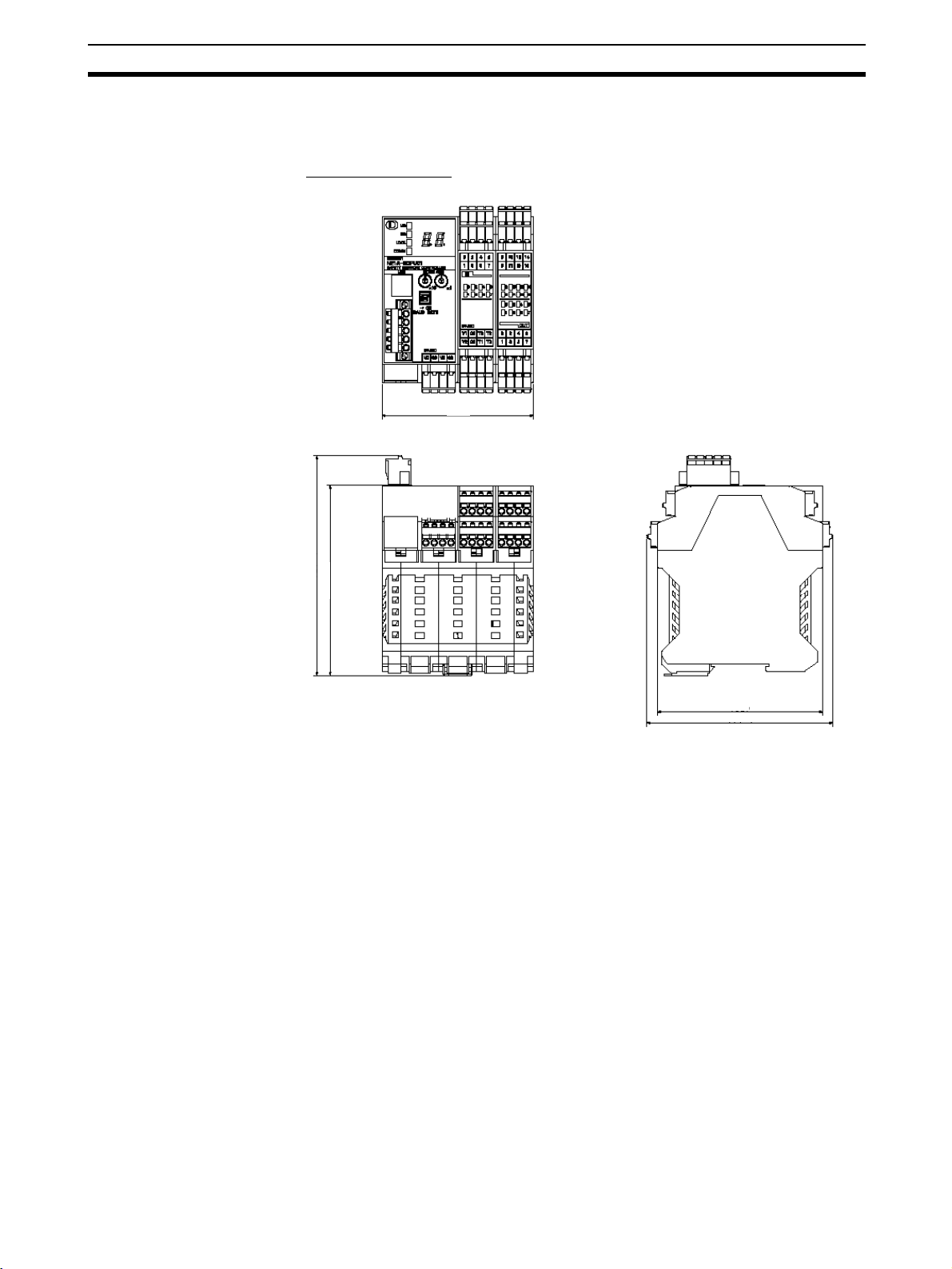
Installation Section 3-1
3-1-3 Dimensions and Weight
Dimensions
■ NE1A-SCPU01(-V1)
99.4
131.4
(114.1)
(99)
111.1
43
Page 78

Installation Section 3-1
■ NE1A-SCPU02
135.6
131.4
(114.1)
(99)
111.1
44
Page 79

Installation Section 3-1
■ NE1A-SCPU01-EIP
113
131.4
(113.6)
(114.4)
(99)
111.1
45
Page 80

Installation Section 3-1
■ NE1A-SCPU02-EIP
158.2
Weight
131.4
(114.4)
(113.6)
(99)
111.1
Model Weight
NE1A-SCPU01(-V1) 460 g max.
NE1A-SCPU02 690 g max.
NE1A-SCPU01-EIP 570 g max.
NE1A-SCPU02-EIP 800 g max.
46
Page 81

Wiring Section 3-2
3-2 Wiring
3-2-1 General Instructions on Wiring
Precaution:
• To prevent wire clippings from getting into the NE1A-series Controller, do
not remove the label on the Controller before wiring has been completed.
• After wiring has been completed, be sure to remove the label from the
Controller to enable heat dissipation for proper cooling.
Label prevents wire
clippings from entering.
• Disconnect the NE1A-series Controller from the power supply before
starting any wiring operations. Devices connected to the Controller may
operate unexpectedly if wiring is performed with the power supply connected.
• Be careful not to get your fingers caught when attaching connectors to the
plugs on the NE1A-series Controller.
!WARNING
Serious injury may possibly occur due to loss of required safety functions. Wire the conductors correctly and verify the operation of the NE1A-series Controller before using the
Controller system in actual operation.
47
Page 82

Wiring Section 3-2
3-2-2 Wiring the Power Supply and I/O Lines
Wire Sizes
Use the following wires to connect external I/O devices to the NE1A-series
Controller.
Solid wire
Stranded (flexible) wire
Recommended Materials and Tools
■ Insulated Pin Terminals
Use a pin terminal with an insulated cover compliant with the DIN 46228-4
standard. Pin terminals similar in appearance but not compliant with the standard may not match the terminal block on the NE1A-series Controller. (The
wiring dimensions are rough standards. Confirm the dimensions beforehand.)
Use wires of the same diameter if two-wire pin terminals are used.
Note • When wiring with pin terminals, be sure to insert pin terminals all the way
• When using two-wire pin terminals, use wires of the same diameter.
• When using two-wire pin terminals, insert the pin terminal so that metal
0.2 to 2.5 mm
0.34 to 1.5 mm
into the terminal block.
portion of the pin terminal is inserted straight into the terminal block, i.e.,
so that the long sides of the insulating cover are vertical.
2
(AWG 24 to AWG 12)
2
(AWG 22 to AWG 16)
48
Page 83
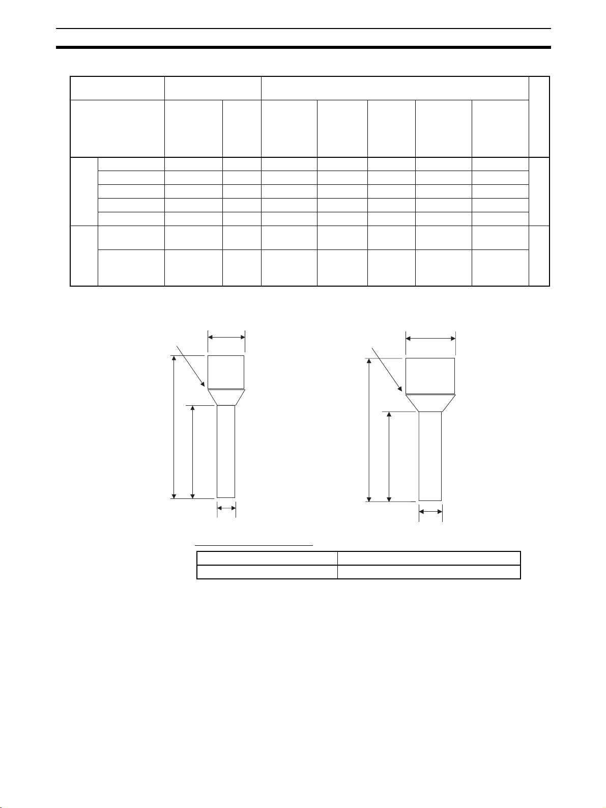
Wiring Section 3-2
Reference Specifications (Product Specifications for Phoenix Contact)
Model of pin
terminal
AI 0,34-8TQ 0.34 22 10 12.5 8 0.8 2.0 *1
AI 0,5-10WH 0.5 20 10 16 10 1.1 2.5
AI 0,75-10GY 0.75 18 10 16 10 1.3 2.8
AI 1-10RD 1.0 18 10 16 10 1.5 3.0
terminals
One-wire pin
AI 1,5-10BK 1.5 16 10 18 10 1.8 3.4
AI-TWIN 2 x
0,75-10GY
AI-TWIN 2 x 1-
10RD
terminals
Two-wire pin
Wire dimensions Pin terminal specifications
Cross-
sectional
area of
conductor
2
(mm
)
AWG Stripped
length of
insulation
(mm)
Overall
length L1
(mm)
Length of
metal
part L2
(mm)
Inner
diameter of
conductor
D1 (mm)
Inner
diameter of
insulative
cover D2
(mm)
2 x 0.75 − 10 17 10 1.8 2.8/5.0 *2
2 x 1 − 10 17 10 2.05 3.4/5.4
*1: One-wire Pin Terminal *2: Two-wire Pin Terminal
Insulated cover
Dia. D2
Insulation
Cover
Dia. D2
Dimensions
Power Supply Selection
L1
L2
Dia. D1
L1
L2
Dia. D1
■ Terminal Crimping Tool
Manufacturer Model
Phoenix Contact CRIMPFOX UD6 or CRIMPFOX ZA3
Use a DC power supply satisfying the following requirements.
• The secondary circuits of the DC power supply must be isolated from the
primary circuit by double insulation or reinforced insulation.
• The DC power supply must satisfy the requirements for class 2 circuits or
limited voltage/current circuits defined in UL 508.
• The output hold time must be 20 ms or longer.
49
Page 84

Wiring Section 3-2
3-2-3 Wiring I/O Devices
Wiring Input Devices
Refer to the following information for input device selection and wiring.
■ Devices with Mechanical Contact Outputs
Examples: Emergency stop buttons and safety limit switches
These devices use both a safety input terminal and test output terminal. A
safety input terminal inputs the test output signal (pulse output) of the NE1Aseries Controller via a contact output device.
V1
4.5 mA typical
Tx
NE1A-series
Controller
INx
Minimum applicable load:
4 mA, 24 VAC
24 VDC
G1
■ Devices with PNP Semiconductor Outputs (Current Sourcing)
Example: Light curtains
A PNP semiconductor output signal from this type of device is input to the
NE1A-series Controller’s safety input terminal.
4.5 mA typical
V1
24 VDC
OSSDx
GND
Tx
NE1A-series
Controller
INx
24 VDC
G1
!WARNING
Serious injury may possibly occur due to loss of required safety functions. Use appropriate components or devices according to the requirements given in the following table.
50
Page 85

Wiring Section 3-2
Controlling devices Requirements
Emergency stop switch Use approved devices with a direct opening mechanism compliant with IEC/
Door interlocking switch or
limit switch
Safety sensor Use approved devices compliant with the relevant product standards, regula-
Relay with forcibly guided contacts Use approved devices with forcibly guided contacts compliant with EN 50205.
Contactor Use contactors with a forcibly guided mechanism and monitor the auxiliary NC
Other devices Evaluate whether devices used are appropriate to satisfy the requirements of
IMPORTANT
EN 60947-5-1.
Use approved devices with a direct opening mechanism compliant with IEC/
EN 60947-5-1 and capable of switching micro-loads of 4 mA at 24 VDC.
tions, and rules in the country where they are used.
For feedback, use devices with contacts capable of switching
micro-loads of 4 mA at 24 VDC.
contact to detect contactor failures.
For feedback, use devices with contacts capable of switching micro-loads of
4 mA at 24 VDC.
the safety category level.
• Properly apply the specified voltage to the NE1A-series Controller’s
inputs. Applying an inappropriate DC voltage or any AC voltage may
cause reduced safety functions, damage to the NE1A-series Controller, or
a fire.
• Be sure to separate I/O cables from high-voltage/current lines.
• Use a total I/O communications cable length of 30 m or less.
• Do not apply the power supply to the test output terminals. Doing so may
result in product damage or burning.
Wiring Output Devices
Refer to the following diagram for selection and wiring of output devices.
NE1A-series
Controller
V2
OUTx
G2
L
0.5 A max.
24 VDC
51
Page 86

Wiring Section 3-2
!WARNING
Serious injury may possibly occur due to breakdown of outputs. Do not connect loads
beyond the rated value to the safety outputs and the test outputs.
Serious injury may possibly occur due to loss of required safety functions. Wire the
NE1A-series Controller properly so that 24-VDC lines do NOT touch the safety outputs
and the test outputs accidentally or unintentionally.
Serious injury may possibly occur due to loss of required safety functions. Ground the 0V line of the power supply for external output devices so that the devices do NOT turn
ON when the safety output line or the test output line is grounded.
Serious injury may possibly occur due to loss of required safety functions. Use appropriate components or devices according to the requirements given in the following table.
Controlling Devices Requirements
Contactor Use contactors with a forcibly guided mechanism and monitor the auxiliary NC
contact to detect contactor failures.
For feedback, use devices with contacts capable of switching micro-loads of
4 mA at 24 VDC.
Other devices Evaluate whether devices used are appropriate to satisfy the requirements of
safety category level.
IMPORTANT
• Be sure to separate I/O cables from high-voltage/current lines.
• Use I/O cables of 30 m or less.
• Do not apply the power supply to the test output terminals. Doing so may
result in product damage or burning.
52
Page 87

Wiring Section 3-2
Examples of I/O Device Connections
Example of Connecting an Emergency Stop Button
S1
11 21
I0
I1
I4
I2
I3
I6
I5
I7
I8
I9
I10
I11
I12
I13
I14
KM1-NC
I15
KM2-NC
S2
12 22
V1
V2
E2
E1
G1 T0
G2
T1
T2
T3
O0
O1
E1 and E2: 24-VDC power supplies
S1: Emergency stop switch
O2 O4 O6
O3 O5
O7
KM1KM2
KM1
KM2
M
S2 Reset switch
KM1 and KM2: Contactors
M: Motor
Note Connect a 24-VDC power supply to terminals V0 and G0 (power supply termi-
nals for internal circuits).
Note This example shows an NE1A-SCPU01(-V1)(-EIP) Controller’s terminal lay-
out.
Example of Connecting Limit Switches (for a Safety Gate)
Open
S1
I0
I1
I4
I2
I3
I6
I5
I7
S2
T1
T2
T3
V1
V2 G2
G1 T0
E2
E1
E1 and E2: 24-VDC power supplies
S1: Safety limit switch
S2: Limit Switch (NO Contact)
KM1 and KM2: Contactors
M: Motor
Note Connect a 24-VDC power supply to terminals V0 and G0 (power supply termi-
nals for internal circuits).
I10
I9I8I11
O0
O2 O4 O6
O1
O3 O5
I12
I13
I14
I15
O7
KM1-NC
KM2-NC
KM1
KM2
KM1KM2
M
53
Page 88

Wiring Section 3-2
Note This example shows an NE1A-SCPU01(-V1)(-EIP) Controller’s terminal lay-
out.
Example of Connecting Two-hand Switches
S11
S12
I0
I1
G1 T0
V1
V2 G2
E2
E1
I4
I2
I3
T1
I6
I5
I7
T2
T3
E1 and E2: 24-VDC power supplies
S11 and S12: Two-hand switches
KM1 and KM2: Contactors
M: Motor
I8
I10
I9
I11
O0
O2 O4 O6
O1
O3 O5
I12
I13
I14
I15
O7
KM1-NC
KM2-NC
KM1
KM2
KM1KM2
M
Note Connect a 24-VDC power supply to terminals V0 and G0 (power supply termi-
nals for internal circuits).
Note This example shows an NE1A-SCPU01(-V1)(-EIP) Controller’s terminal lay-
out.
54
Page 89

Wiring Section 3-2
Example of Connecting a Light Curtain
Receiver - OSSD1 (Green)
I6
I4
Receiver - OSSD2 (White)
I2
I0
I3
I1
I5
I7
I8
I9
I10 I12
I11
I13
I14
I15
KM1- NC
KM2- NC
KM1
Emitter: +24 V (Brown)
Receiver: +24 V (Brown)
Emitter: 0 V (Blue), shield
Receiver: 0 V (Blue), shield
S1
Note Connect a 24-VDC power supply to terminals V0 and G0 (power supply termi-
V1
G1 T0
G2
V2
E2
E1
S2
Rest input (Yellow)
Red: Open
Interlock (White)
Test input (Green)
T1
T2
T3
O0
O1
Light Curtain: OMRON F3SN-A
Emitter
nals for the internal circuits).
O2
O3
RS-485 (Gray)
RS-485 (Pink)
O6
O4
O5
KM2
Receiver
O7
KM1
External relay monitor (Red)
Auxiliary output (Yellow)
KM2
E1 and E2: 24 VDC power supplies
S1: External test switch
S2: Lockout reset switch
KM1 and KM2: Contactors
M: Motor
M
Note This example shows an NE1A-SCPU01(-V1)(-EIP) Controller’s terminal lay-
out.
55
Page 90

Wiring Section 3-2
Example of Connecting a User Mode Switch
S1
I0 I2 I4 I6
I1 I3 I5 I7
V1 G1 T0 T2
V2 G2 T1 T3
I8 I10 I12 I14
I9 I11 I13 I15
O0 O2 O4 O6
O1 O3 O5 O7
E1 and E2: 24 VDC power supplies
E2
E1
S1: User mode switch
Note Connect a 24-VDC power supply to terminals V0 and G0 (power supply termi-
nals for internal circuits).
56
Note This example shows an NE1A-SCPU01(-V1)(-EIP) Controller’s terminal lay-
out.
Page 91

Wiring Section 3-2
3-2-4 DeviceNet Wiring
Wire the DeviceNet communications cable as shown in the following diagram.
Stickers are placed on the communication connectors based on the color of
each communications wire. By matching the communications wire colors with
the connector sticker colors, you can check to see if wires are in the correct
locations. The colors of the wires are as follows:
Color Description
Red V+
White Signal (CAN H)
-Drain
Blue Signal (CAN L)
Black V−
IMPORTANT
Note Refer to the DeviceNet Operation Manual (W267) for further information on
• Turn OFF the power supply to the NE1A-series Controller, to all nodes on
the network, and to communications lines before starting any wiring operations.
• Tighten the DeviceNet connector to the appropriate torque (0.25 to
0.3 N·m).
• Separate the DeviceNet communications cables from high-voltage/current
lines.
wiring.
3-2-5 Wiring the USB Connector
A computer is connected to use the Network Configurator.
Use a commercially available USB-A to USB-B Male/Male cable to make the
connection.
IMPORTANT Use a USB cable of 3 meters max.
57
Page 92

Wiring Section 3-2
3-2-6 Ethernet (EtherNet/IP) Network Installation
Basic Installation
Precautions
Recommended
Network Devices
Part Maker Model number Inquires
Switching Hub OMRON W4S1-03B
Cisco Systems, Inc. Consult the manufacturer. Cisco Systems, Inc. Main Corporate HQ
Contec USA, Inc. Consult the manufacturer. CONTEC USA Inc.
Phoenix Contact Consult the manufacturer. Phoenix Contact USA Customer Service
Twisted-pair
cable
Connectors
(Modular plug)
Boots Tsuko Company MK boot (IV) LV Tsuko Company Japan Headquarters
100BASE-TX
Fujikura F-LINK-E 0.5mm × 4P Fujikura America, Inc.
EtherNet/IP compliant cable --STP Plug
Panduit Corporation MPS588 Panduit Corporation US Headquarters
• Take the greatest care when installing the Ethernet System, being sure to
follow ISO 8802-3 specifications. You must obtain a copy of these specifications and be sure you understand them before attempting to install an
Ethernet System.
• Unless you are already experienced in installing communications systems, we strongly recommend that you employ a professional to install
your system.
• Do not install Ethernet equipment near sources of noise. If a noisy environment is unavoidable, take adequate measures against noise interference, such as installing network components in grounded metal cases or
using optical cable in the system.
The following table shows the devices recommended for use with the NE1Aseries Controller.
OMRON Corporation
W4S1-05B
W4S1-05C
Precautions
Precautions on Laying
Twisted-pair Cable
Note • Ask the switching hub manufacturer for setting procedures for the switch-
ing hub.
• Install the switching hub so that its environmental resistance capabilities
are not exceeded.
Ask the switching hub manufacturer for information on the environmental
resistance of the switch hub.
• Noise resistance may be reduced by ground loops, which can occur due
to improper shield connections and grounding. Ground the shield at one
location, as shown in the following diagram.
• Do not connect a shield at the NE1A-series Controller connector.
• If a cable connects two hubs, connect the shields at only one end.
58
Page 93

Wiring Section 3-2
Hub Hub
Connector Connector Connector Connector Connector
GR GR
STP
(Shield)
Connect shield.
Do not connect shield.
STP
(Shield)
STP
(Shield)
ED Router
Connector
ED Router
Connector
FG
terminal
FG
terminal
• Press the cable connector in firmly until it locks into place at both the
switching hub and the NE1A-series Controller.
• Do not lay the twisted-pair cable together with high-voltage lines.
• Do not lay the twisted-pair cable near devices that generate noise.
• Do not lay the twisted-pair cable in locations subject to high temperatures
or high humidity.
• Do not lay the twisted-pair cable in locations subject to excessive dirt and
dust or to oil mist or other contaminants.
Switching Hub Installation
Environment Precautions
Switching Hub
Connection Methods
• Do not ground the switching hub in the same location as a drive-system
component such as an inverter.
• Always use a dedicated power supply for the switching hub’s power supply. Do not use the same power supply used for other equipment, such as
an I/O power supply, motor power supply, or control power supply.
• Before installation, check the switching hub’s environment-resistance
specifications, and use a switching hub appropriate for the ambient conditions. Contact the switching hub manufacturer for details on switching
hub’s environment-resistance specifications.
• Connect two hubs to each other as follows: Connect an MDI port to an
MDI-X port with a straight cable; connect two MDI ports with a cross
cable; and connect two MDI-X ports with a cross cable.
Note It is very difficult to distinguish cross cables and straight cables by
appearance. Incorrect cables will cause communications to fail. We
recommend using cascade connections with straight cables whenever possible.
MDI-X port
(cross)
MDI ports
Switching
Hub
Switching
Hub
Switching
Hub
: Straight cable
: Cross cable
Switching
Hub
• Some switching hubs can automatically distinguish between MDI and
MDI-X. When this kind of switching hub is being used, straight cable can
be used between switching hubs.
59
Page 94

Wiring Section 3-2
Note NE1A-series Controller link settings must match the communications mode
settings of connected switching hubs. If they do not match, links will be unstable and normal communications will not be possible. For EtherNet/IP I/O communications (tag data link communications) with an EtherNet/IP standard
originator, it is recommended that auto-negotiation or 100M full-duplex communications be set for the Controller and the switching hubs.
NE1A-series
Controller
Switching
hub
Auto-negotiation Recommended Not connectible Connectible Not connectible Connectible
10 Mbps Full Not connectible Connectible Not connectible Not connectible Not connectible
Half Connectible Not connectible Connectible Not connectible Not connectible
100 Mbps Full Not connectible Not connectible Not connectible Recommended Not connectible
Half Connectible Not connectible Not connectible Not connectible Connectible
Auto-
negotiation
10 Mbps 100 Mbps
Full Half Full Half
Ethernet Connectors The following standards and specifications apply to the connectors for the
Ethernet twisted-pair cable.
• Electrical specifications: Conforming to IEEE802.3 standards.
• Connector structure: RJ45 8-pin Modular Connector
(conforming to ISO 8877)
Connector pin Signal name Abbr. Signal direction
1 Transmission data + TD+ Output
2 Transmission data – TD– Output
3 Reception data + RD+ Input
4 Not used. --- --5 Not used. --- --6 Reception data – RD– Input
7 Not used. --- --8 Not used. --- --Hood Frame ground FG ---
Note The NE1A-series Controller Ethernet ports support the auto-MDI/MDI-X func-
Connecting the Cable
!Caution Turn OFF the power to the NE1A-series Controller before connecting or dis-
!Caution Allow enough space for the bending radius of the twisted-pair cable as shown
60
tionality, so either a straight or cross cable can be used.
connecting twisted-pair cable.
in below.
Page 95

Wiring Section 3-2
NE1A
35 mm
1,2,3... 1. Lay the twisted-pair cable.
2. Connect the cable to the switching hub. Be sure to press in the cable until
it locks into place. This procedure should only be performed by qualified
personnel.
3. Connect the twisted-pair cable to the connector on the NE1A-series Controller.
Be sure to press the connectors (both the switching hub side and Ethernet
side) until they lock into place.
61
Page 96

Page 97

DeviceNet Communications Functions
4-1 Initial Setting. . . . . . . . . . . . . . . . . . . . . . . . . . . . . . . . . . . . . . . . . . . . . . . . . . 64
4-1-1 Hardware Setup . . . . . . . . . . . . . . . . . . . . . . . . . . . . . . . . . . . . . . . . 64
4-1-2 Software Settings . . . . . . . . . . . . . . . . . . . . . . . . . . . . . . . . . . . . . . . 66
4-2 Network Status Indication. . . . . . . . . . . . . . . . . . . . . . . . . . . . . . . . . . . . . . . . 67
4-3 Remote I/O Allocations . . . . . . . . . . . . . . . . . . . . . . . . . . . . . . . . . . . . . . . . . 68
4-3-1 Remote I/O Area Allocation Overview . . . . . . . . . . . . . . . . . . . . . . 68
4-3-2 Remote I/O Area Attributes . . . . . . . . . . . . . . . . . . . . . . . . . . . . . . . 69
4-3-3 Remote I/O Area Data Configuration. . . . . . . . . . . . . . . . . . . . . . . . 70
4-4 Safety Master Function . . . . . . . . . . . . . . . . . . . . . . . . . . . . . . . . . . . . . . . . . . 82
4-4-1 Safety I/O Communications as Safety Master . . . . . . . . . . . . . . . . . 82
4-4-2 Safety I/O Connection Settings . . . . . . . . . . . . . . . . . . . . . . . . . . . . 83
4-4-3 Stopping/Resetting Communications after
an Error . . . . . . . . . . . . . . . . . . . . . . . . . . . 85
4-5 Safety Slave Function . . . . . . . . . . . . . . . . . . . . . . . . . . . . . . . . . . . . . . . . . . . 88
4-5-1 Safety I/O Communications as Safety Slave . . . . . . . . . . . . . . . . . . 88
4-5-2 Creating I/O Data (Safety Slave I/O) to Use as Safety Slave . . . . . . 89
4-6 Standard Slave Function . . . . . . . . . . . . . . . . . . . . . . . . . . . . . . . . . . . . . . . . . 92
4-6-1 Standard I/O Communications as Standard Slave . . . . . . . . . . . . . . 92
4-6-2 Creating I/O Data (Slave I/O) to Use as Standard Slave . . . . . . . . . 92
Unit Ver. 1.0 or Later
SECTION 4
63
Page 98

Initial Setting Section 4-1
4-1 Initial Setting
4-1-1 Hardware Setup
Node Address Setting
Set the DeviceNet node address using the rotary switches on the front of the
NE1A-series Controller.
Software Setting
Method Two-digit decimal
number
Range 0 to 63
Note The node address is set to 63 at the factory.
Any node address in the setting range can be used as long as the same
address is not used by another node. If a value between 64 and 99 is set on
the rotary switches, the node address can be set using a software setting on
the Network Configurator.
Use the following procedure to set the node address using the Network Configurator.
1. Turn OFF the power and then set the rotary switches to a number between
64 and 99 (software setting).
2. Turn ON the power. The NE1A-series Controller will operate using the previous node address (factory set to 63).
3. Reset to the default settings using the Network Configurator’s RESET
command.
The configuration information held in the device will be initialized.
4. Set the node address from the Network Configurator.
From here on, the NE1A-series Controller will operate with the node address
set in the software setting.
64
IMPORTANT
• Turn OFF power to the NE1A-series Controller before setting the node
addresses.
• Do not change the rotary switches while the power is ON. The NE1Aseries Controller will detect this as a change in the configuration and will
switch to Abort State.
• A node address duplication error will occur if the same address is set for
more than one node. Communications will not start if this error occurs.
Note Use a small flat-blade screwdriver to set the rotary switches, being careful not
to scratch them.
Page 99

Initial Setting Section 4-1
Baud Rate Setting
The DeviceNet baud rate is set using the DIP switch on the front of the NE1Aseries Controller. The baud rates settings are shown in the following table:
Pin Baud rate
1 2 3 4
OFF OFF OFF OFF 125 kbit/s
ON OFF OFF OFF 250 kbit/s
OFF ON OFF OFF 500 kbit/s
ON ON OFF OFF Software setting
ON or
OFF
ON or
OFF
Note The baud rate is set to 125 kbit/s at the factory.
Software Setting
The Network Configurator can be used to set the baud rate. The procedure is
as follows:
1. Turn OFF the power and change the DIP switch to the “software setting.”
2. Turn ON the power. When power is turned ON, the NE1A-series Controller
will operate at the previous baud rate (default setting: 125 kbit/s).
3. Reset to the default settings using the Network Configurator’s RESET
command.
The configuration information held in the device will be initialized.
4. Set the baud rate from the Network Configurator.
5. Reset the NE1A-series Controller by cycling the power or using the NE1Aseries Controller RESET command from the Network Configurator. The
NE1A-series Controller will then operate with the baud rate set from the
Network Configurator, i.e., the software setting.
ON or
OFF
ON or
OFF
ON OFF
ON or
OFF
ON Automatic baud rate
detection
Automatic Baud Rate Detection
IMPORTANT
The NE1A-series Controller’s baud rate can be set automatically to match the
baud rate of the master on the network. The baud rate must be set in at least
one Safety Master or Standard Master on the network. After turning ON the
power, the baud rate is set when establishing communications, and the baud
rate setting is stored until the next time power is turned ON.
• Turn OFF power to the NE1A-series Controller before setting the DIP
switch.
• Do not change the DIP switch setting while the power supply is ON. The
NE1A-series Controller will detect this as a change in the configuration
and will switch to ABORT State.
• The baud rate must be the same for all nodes (masters and slaves) on the
network.
65
Page 100

Initial Setting Section 4-1
4-1-2 Software Settings
Disabling DeviceNet Communications (Standalone)
When DeviceNet Communications are disabled, the NE1A-series Controller
stops all DeviceNet communications and operates as a Standalone Controller. The default is to have DeviceNet communications enabled (normal mode).
Make the setting from the Network Configurator. After the setting has been
made, a reset command will be sent from the Network Configurator to the
NE1A-series Controller to enable the setting.
Setting Description
Enabled (Normal Mode) DeviceNet communications enabled.
Disabled (Standalone Mode) DeviceNet communications disabled. The SNC will
operate as a Standalone Controller. “nd” will be displayed on
the 7-segment display.
IMPORTANT
• When DeviceNet communications are disabled, connect the NE1A-series
Controller to the Network Configurator via a USB connection or via EtherNet/IP (for Controllers that support EtherNet/IP).
• When DeviceNet communications are disabled, operation using the Network Configurator can be performed via a USB connection or via EtherNet/IP (for Controllers that support EtherNet/IP).
66
 Loading...