

Page 1

Cat. No. Z912-E1-01
NE1A Series
NE1A-EDR01
EtherNet/IP-DeviceNet Router
OPERATION MANUAL
Page 2

NE1A Series EtherNet/IP-DeviceNet Router: NE1A-EDR01
Operation Manual
Produced July 2007
Page 3

iv
Page 4

Notice:
OMRON products are manufactured for use according to proper procedures by a qualified operator
and only for the purposes described in this manual.
The following conventions are used to indicate and classify precautions in this manual. Always heed
the information provided with them. Failure to heed precautions can
result in injury to people or damage to property.
!WARNING Indicates a potentially hazardous situation which, if not avoided, will result in minor or
moderate injury, or may result in serious injury or death. Additionally, there may be significant property damage.
!Caution Indicates a potentially hazardous situation which, if not avoided, may result in minor or
moderate injury, or property damage.
Indicates general prohibitions for which there is no specific symbol.
Indicates general mandatory actions for which there is no specific symbol.
OMRON Product References
All OMRON products are capitalized in this manual. The word “Unit” is also capitalized when it refers to
an OMRON product, regardless of whether or not it appears in the proper name of the product.
The abbreviation “PLC” means Programmable Controller. “PC” is used, however, in some Programming Device displays to mean Programmable Controller.
Visual Aids
The following headings appear in the left column of the manual to help you locate different types of
information.
IMPORTANT Indicates important information on what to do or not to do to prevent failure to
operation, malfunction, or undesirable effects on product performance.
Note Indicates information of particular interest for efficient and convenient opera-
tion of the product.
1,2,3... 1. Indicates lists of one sort or another, such as procedures, checklists, etc.
v
Page 5

Trademarks and Copyrights
r
f
CIP, EtherNet/IP, DeviceNet, and DeviceNet Safety are registered trademarks of the Open DeviceNet
Vendors Association.
Windows is a registered trademark of Microsoft Corporation.
Other product names and company names in this manual are trademarks or registered trademarks of
their respective companies.
OMRON, 2007
All rights reserved. No part of this publication may be reproduced, stored in a retrieval system, or transmitted, in any form, o
by any means, mechanical, electronic, photocopying, recording, or otherwise, without the prior written permission o
OMRON.
No patent liability is assumed with respect to the use of the information contained herein. Moreover, because OMRON is constantly striving to improve its high-quality products, the information contained in this manual is subject to change without
notice. Every precaution has been taken in the preparation of this manual. Nevertheless, OMRON assumes no responsibility
for errors or omissions. Neither is any liability assumed for damages resulting from the use of the information contained in
this publication.
vi
Page 6

TABLE OF CONTENTS
PRECAUTIONS . . . . . . . . . . . . . . . . . . . . . . . . . . . . . . . . . . . xv
1 Intended Audience. . . . . . . . . . . . . . . . . . . . . . . . . . . . . . . . . . . . . . . . . . . . . . . . . . . . . . . . . xvi
2 General Precautions. . . . . . . . . . . . . . . . . . . . . . . . . . . . . . . . . . . . . . . . . . . . . . . . . . . . . . . . xvi
3 Precautions for Safe Use . . . . . . . . . . . . . . . . . . . . . . . . . . . . . . . . . . . . . . . . . . . . . . . . . . . . xvi
4 Regulations and Standards. . . . . . . . . . . . . . . . . . . . . . . . . . . . . . . . . . . . . . . . . . . . . . . . . . . xviii
SECTION 1
Overview . . . . . . . . . . . . . . . . . . . . . . . . . . . . . . . . . . . . . . . . . 1
1-1 EtherNet/IP-DeviceNet Router . . . . . . . . . . . . . . . . . . . . . . . . . . . . . . . . . . . . . . . . . . . . . . . 2
1-2 Nomenclature. . . . . . . . . . . . . . . . . . . . . . . . . . . . . . . . . . . . . . . . . . . . . . . . . . . . . . . . . . . . . 4
SECTION 2
Installation and Network Connections . . . . . . . . . . . . . . . . . 5
2-1 Installation . . . . . . . . . . . . . . . . . . . . . . . . . . . . . . . . . . . . . . . . . . . . . . . . . . . . . . . . . . . . . . . 6
2-2 Wiring . . . . . . . . . . . . . . . . . . . . . . . . . . . . . . . . . . . . . . . . . . . . . . . . . . . . . . . . . . . . . . . . . . 9
2-3 Connecting to DeviceNet. . . . . . . . . . . . . . . . . . . . . . . . . . . . . . . . . . . . . . . . . . . . . . . . . . . .16
2-4 Connecting to Ethernet (EtherNet/IP) . . . . . . . . . . . . . . . . . . . . . . . . . . . . . . . . . . . . . . . . . . 18
2-5 ED Router Settings . . . . . . . . . . . . . . . . . . . . . . . . . . . . . . . . . . . . . . . . . . . . . . . . . . . . . . . . 23
SECTION 3
Status Indicators and Troubleshooting. . . . . . . . . . . . . . . . . 25
3-1 Status Indicators. . . . . . . . . . . . . . . . . . . . . . . . . . . . . . . . . . . . . . . . . . . . . . . . . . . . . . . . . . . 26
3-2 Troubleshooting. . . . . . . . . . . . . . . . . . . . . . . . . . . . . . . . . . . . . . . . . . . . . . . . . . . . . . . . . . . 29
3-3 Error History . . . . . . . . . . . . . . . . . . . . . . . . . . . . . . . . . . . . . . . . . . . . . . . . . . . . . . . . . . . . . 32
SECTION 4
Accessing Devices by UDP . . . . . . . . . . . . . . . . . . . . . . . . . . . 37
4-1 Overview . . . . . . . . . . . . . . . . . . . . . . . . . . . . . . . . . . . . . . . . . . . . . . . . . . . . . . . . . . . . . . . . 38
4-2 Formats . . . . . . . . . . . . . . . . . . . . . . . . . . . . . . . . . . . . . . . . . . . . . . . . . . . . . . . . . . . . . . . . . 39
4-3 Operating Examples. . . . . . . . . . . . . . . . . . . . . . . . . . . . . . . . . . . . . . . . . . . . . . . . . . . . . . . . 41
4-4 Mitsubishi Ethernet Interface Module Settings . . . . . . . . . . . . . . . . . . . . . . . . . . . . . . . . . . . 43
4-5 Sample Ladder Programs. . . . . . . . . . . . . . . . . . . . . . . . . . . . . . . . . . . . . . . . . . . . . . . . . . . .45
4-6 NE1A Series Monitoring. . . . . . . . . . . . . . . . . . . . . . . . . . . . . . . . . . . . . . . . . . . . . . . . . . . .59
4-7 DST1 Series Monitoring . . . . . . . . . . . . . . . . . . . . . . . . . . . . . . . . . . . . . . . . . . . . . . . . . . . .66
Appendices
A Specifications and Dimensions . . . . . . . . . . . . . . . . . . . . . . . . . . . . . . . . . . . . . . . . . . . . . . . 81
B Settings from the Network Configurator . . . . . . . . . . . . . . . . . . . . . . . . . . . . . . . . . . . . . . . 83
Glossary . . . . . . . . . . . . . . . . . . . . . . . . . . . . . . . . . . . . . . . . . . 85
Revision History . . . . . . . . . . . . . . . . . . . . . . . . . . . . . . . . . . . 89
vii
Page 7

TABLE OF CONTENTS
viii
Page 8

About this Manual:
This manual describes the installation and operation of the NE1A-EDR01 EtherNet/IP-DeviceNet
Router. The NE1A-EDR01 EtherNet/IP-DeviceNet Router was developed using OMRON‘s advanced
control technology and vast know-how. It functions to route FA data between EtherNet/IP and
DeviceNet networks.
Please read this manual carefully and be sure you understand the information provided before
attempting to install or operate the NE1A-EDR01 EtherNet/IP-DeviceNet Router. The following manuals are also related to the NE1A-EDR01 EtherNet/IP-DeviceNet Router or NE1A-series Safety Network Controllers. Refer to these manuals as required during installation and operation.
EtherNet/IP-DeviceNet Router Operation Manual (this manual) (Z912)
This manual describes the specifications, functions, and application methods of the EtherNet/IPDeviceNet Router in detail.
DeviceNet Safety System Configuration Manual (Z905)
This manual explains how to configure the DeviceNet Safety system using the Network Configurator.
DeviceNet Safety NE1A Series Safety Network Controller Operation Manual (Z906)
This manual describes the specifications, functions, and usage of the NE1A-SCPU01 and NE1ASCPU02.
DeviceNet Safety Safety I/O Terminal Operation Manual (Z904)
This manual describes the DST1-series Slave models, specifications, functions, and application methods in detail.
DeviceNet Operation Manual (W267)
This manual describes the construction and connection of a DeviceNet network. It provides detailed
information on the installation and specifications of cables, connectors, and other peripheral equipment used in the network, and on the supply of communications power. Obtain this manual and gain a
firm understanding of its contents before using a DeviceNet system.
ix
Page 9

x
Page 10

Read and Understand this Manual
Please read and understand this manual before using the product. Please consult your OMRON
representative if you have any questions or comments.
Warranty and Limitations of Liability
WARRANTY
OMRON's exclusive warranty is that the products are free from defects in materials and workmanship for a
period of one year (or other period if specified) from date of sale by OMRON.
OMRON MAKES NO WARRANTY OR REPRESENTATION, EXPRESS OR IMPLIED, REGARDING NONINFRINGEMENT, MERCHANTABILITY, OR FITNESS FOR PARTICULAR PURPOSE OF THE
PRODUCTS. ANY BUYER OR USER ACKNOWLEDGES THAT THE BUYER OR USER ALONE HAS
DETERMINED THAT THE PRODUCTS WILL SUITABLY MEET THE REQUIREMENTS OF THEIR
INTENDED USE. OMRON DISCLAIMS ALL OTHER WARRANTIES, EXPRESS OR IMPLIED.
LIMITATIONS OF LIABILITY
OMRON SHALL NOT BE RESPONSIBLE FOR SPECIAL, INDIRECT, OR CONSEQUENTIAL DAMAGES,
LOSS OF PROFITS OR COMMERCIAL LOSS IN ANY WAY CONNECTED WITH THE PRODUCTS,
WHETHER SUCH CLAIM IS BASED ON CONTRACT, WARRANTY, NEGLIGENCE, OR STRICT
LIABILITY.
In no event shall the responsibility of OMRON for any act exceed the individual price of the product on which
liability is asserted.
IN NO EVENT SHALL OMRON BE RESPONSIBLE FOR WARRANTY, REPAIR, OR OTHER CLAIMS
REGARDING THE PRODUCTS UNLESS OMRON'S ANALYSIS CONFIRMS THAT THE PRODUCTS
WERE PROPERLY HANDLED, STORED, INSTALLED, AND MAINTAINED AND NOT SUBJECT TO
CONTAMINATION, ABUSE, MISUSE, OR INAPPROPRIATE MODIFICATION OR REPAIR.
xi
Page 11

Application Considerations
SUITABILITY FOR USE
OMRON shall not be responsible for conformity with any standards, codes, or regulations that apply to the
combination of products in the customer's application or use of the products.
At the customer's request, OMRON will provide applicable third party certification documents identifying
ratings and limitations of use that apply to the products. This information by itself is not sufficient for a
complete determination of the suitability of the products in combination with the end product, machine,
system, or other application or use.
The following are some examples of applications for which particular attention must be given. This is not
intended to be an exhaustive list of all possible uses of the products, nor is it intended to imply that the uses
listed may be suitable for the products:
• Outdoor use, uses involving potential chemical contamination or electrical interference, or conditions or
uses not described in this manual.
• Nuclear energy control systems, combustion systems, railroad systems, aviation systems, medical
equipment, amusement machines, vehicles, safety equipment, and installations subject to separate
industry or government regulations.
• Systems, machines, and equipment that could present a risk to life or property.
Please know and observe all prohibitions of use applicable to the products.
NEVER USE THE PRODUCTS FOR AN APPLICATION INVOLVING SERIOUS RISK TO LIFE OR
PROPERTY WITHOUT ENSURING THAT THE SYSTEM AS A WHOLE HAS BEEN DESIGNED TO
ADDRESS THE RISKS, AND THAT THE OMRON PRODUCTS ARE PROPERLY RATED AND INSTALLED
FOR THE INTENDED USE WITHIN THE OVERALL EQUIPMENT OR SYSTEM.
PROGRAMMABLE PRODUCTS
OMRON shall not be responsible for the user's programming of a programmable product, or any
consequence thereof.
xii
Page 12

Disclaimers
CHANGE IN SPECIFICATIONS
Product specifications and accessories may be changed at any time based on improvements and other
reasons.
It is our practice to change model numbers when published ratings or features are changed, or when
significant construction changes are made. However, some specifications of the products may be changed
without any notice. When in doubt, special model numbers may be assigned to fix or establish key
specifications for your application on your request. Please consult with your OMRON representative at any
time to confirm actual specifications of purchased products.
DIMENSIONS AND WEIGHTS
Dimensions and weights are nominal and are not to be used for manufacturing purposes, even when
tolerances are shown.
PERFORMANCE DATA
Performance data given in this manual is provided as a guide for the user in determining suitability and does
not constitute a warranty. It may represent the result of OMRON's test conditions, and the users must
correlate it to actual application requirements. Actual performance is subject to the OMRON Warranty and
Limitations of Liability.
ERRORS AND OMISSIONS
The information in this manual has been carefully checked and is believed to be accurate; however, no
responsibility is assumed for clerical, typographical, or proofreading errors, or omissions.
xiii
Page 13

xiv
Page 14

PRECAUTIONS
1 Intended Audience . . . . . . . . . . . . . . . . . . . . . . . . . . . . . . . . . . . . . . . . . . . . . xvi
2 General Precautions . . . . . . . . . . . . . . . . . . . . . . . . . . . . . . . . . . . . . . . . . . . . xvi
3 Precautions for Safe Use. . . . . . . . . . . . . . . . . . . . . . . . . . . . . . . . . . . . . . . . . xvi
4 Regulations and Standards . . . . . . . . . . . . . . . . . . . . . . . . . . . . . . . . . . . . . . . xviii
xv
Page 15

Intended Audience 1
1 Intended Audience
This manual is intended for the following personnel, who must have knowledge of electrical systems (an electrical engineer or the equivalent).
• Personnel in charge of introducing FA and safety systems into production
facilities
• Personnel in charge of designing FA and safety systems
• Personnel in charge of managing FA facilities
• Personnel who have the qualifications, authority, and obligation to provide
safety during each of the following product phases: mechanical design,
installation, operation, maintenance, and disposal
2 General Precautions
The user must operate the product according to the performance specifications described in the operation manuals.
Before using the product under conditions which are not described in the
manual or applying the product to nuclear control systems, railroad systems,
aviation systems, vehicles, combustion systems, medical equipment, amusement machines, safety equipment, and other systems, machines, and equipment that may have a serious influence on lives and property if used
improperly, consult your OMRON representative.
Make sure that the ratings and performance characteristics of the product are
sufficient for the systems, machines, and equipment, and be sure to provide
the systems, machines, and equipment with double safety mechanisms.
This manual provides information for programming and operating the Unit. Be
sure to read this manual before attempting to use the Unit and keep this manual close at hand for reference during operation.
!WARNING It is extremely important that a PLC and all PLC Units be used for the speci-
fied purpose and under the specified conditions, especially in applications that
can directly or indirectly affect human life. You must consult with your OMRON
representative before applying a PLC System to the above-mentioned applications
3 Precautions for Safe Use
■ Handling with Care
Do not drop the EtherNet/IP-DeviceNet Router or subject it to excessive vibration or mechanical shock. The EtherNet/IP-DeviceNet Router may be damaged and may not function properly.
■ Installation and Storage Environment
Do not use or store the EtherNet/IP-DeviceNet Router in any of the following
locations:
• Locations subject to direct sunlight
• Locations subject to temperatures or humidity outside the range specified
in the specifications
• Locations subject to condensation as the result of severe changes in temperature
• Locations subject to corrosive or flammable gases
• Locations subject to dust (especially iron dust) or salts
xvi
Page 16

Precautions for Safe Use 3
• Locations subject to water, oil, or chemicals
• Locations subject to shock or vibration
Take appropriate and sufficient measures when installing systems in the following locations. Inappropriate and insufficient measures may result in malfunction.
• Locations subject to static electricity or other forms of noise
• Locations subject to strong electromagnetic fields
• Locations subject to possible exposure to radioactivity
• Locations close to power supplies
■ Installation and Mounting
• Use the EtherNet/IP-DeviceNet Router within an enclosure with IP54 protection or higher according to IEC/EN 60529.
• Use DIN rail (TH35-7.5/TH35-15 according to IEC 60715) to install the
EtherNet/IP-DeviceNet Router into the control panel. Mount the EtherNet/
IP-DeviceNet Router to the DIN rail using PFP-M End Plates (not included
with the EtherNet/IP-DeviceNet Router) to prevent it falling off the DIN rail
because of vibration.
• Space must be provided around the EtherNet/IP-DeviceNet Router, at
least 5 mm from its side and at least 50 mm from its top and bottom surfaces, for ventilation and wiring.
■ Installation and Wiring
• Use the following to wire external I/O devices to the EtherNet/IPDeviceNet Router.
Solid wire
Stranded (flexible) wire
0.2 to 2.5 mm
0.34 to 1.5 mm2 (AWG 22 to AWG 16)
Stranded wires should be prepared by attaching insulated bar
terminals (DIN 46228-4 standard compatible) to the ends before
connecting them.
2
(AWG 24 to AWG 12)
• Disconnect the EtherNet/IP-DeviceNet Router from the power supply
before starting wiring.
• Properly apply the specified voltage to the EtherNet/IP-DeviceNet Router
inputs. Applying an inappropriate DC voltage or any AC voltage may interfere with functionality, may reduce safety, or may cause the EtherNet/IPDeviceNet Router to be damaged or burnt.
• Be sure to separate the communications cables and I/O cables from near
high-voltage/high-current lines.
• Be cautious not to get your fingers caught when attaching connectors to
the plugs on the EtherNet/IP-DeviceNet Router.
• Tighten the DeviceNet connector screws correctly (0.25 to 0.3 N·m).
• Incorrect wiring may lead to loss of safety functions. Wire conductors correctly and verify the operation of the EtherNet/IP-DeviceNet Router before
using the system in which the EtherNet/IP-DeviceNet Router is incorporated.
• After wiring is completed, be sure to remove label for wire clipping prevention on the EtherNet/IP-DeviceNet Router to enable heat to escape or
proper cooling.
■ Power Supply Selection
Use a DC power supply satisfying the following requirements.
xvii
Page 17

Regulations and Standards 4
• The secondary circuits of the DC power supply must be isolated from the
primary circuit by double insulation or reinforced insulation.
• The DC power supply must satisfy the requirements for class 2 circuits or
limited voltage/current circuits given in UL 508.
• The output hold time must be 20 ms or longer.
■ Periodic Inspections and Maintenance
• Disconnect the EtherNet/IP-DeviceNet Router from the power supply
before replacing the EtherNet/IP-DeviceNet Router. Devices connected to
the EtherNet/IP-DeviceNet Router may operate unexpectedly.
• Do not disassemble, repair, or modify the EtherNet/IP-DeviceNet Router.
Doing so may lead to loss of safety functions.
■ Disposal
• Be cautions not to injure yourself when dismantling the EtherNet/IPDeviceNet Router.
4 Regulations and Standards
The EtherNet/IP-DeviceNet Router has been certified as follows:
Certifying organization Standards
UL UL508, UL1604,
CSA22.2 No142, CSA22.2 No213
xviii
Page 18

This section introduced the EtherNet/IP-DeviceNet Router and it’s functionality.
1-1 EtherNet/IP-DeviceNet Router . . . . . . . . . . . . . . . . . . . . . . . . . . . . . . . . . . . . 2
1-1-1 Accessing All Devices on a Network from a Network Configurator 2
1-1-2 Monitoring DeviceNet or DeviceNet Safety Systems via Ethernet
from Controllers Made by Other Manufacturers . . . . . . . . . . . . . . . 3
1-2 Nomenclature . . . . . . . . . . . . . . . . . . . . . . . . . . . . . . . . . . . . . . . . . . . . . . . . . 4
SECTION 1
Overview
1
Page 19
EtherNet/IP-DeviceNet Router Section 1-1
r
1-1 EtherNet/IP-DeviceNet Router
The NE1A-EDR01 EtherNet/IP-DeviceNet Router is an FA router with one
Ethernet port and one DeviceNet port, and is used for routing messages
between Ethernet and DeviceNet Networks. In this manual the NE1A-EDR01
EtherNet/IP-DeviceNet Router is called the “ED Router.”
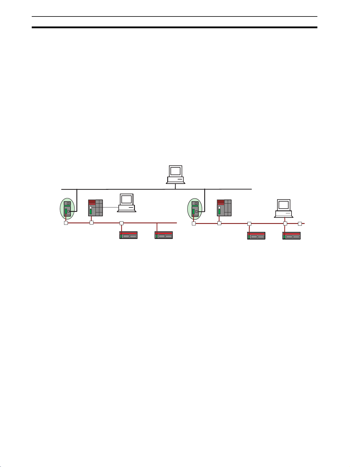
1-1-1 Accessing All Devices on a Network from a Network Configurator
Using an ED Router makes it possible to set devices, such as NE1A-series
Controllers and DST1-series Slaves, from a Network Configurator running on
a PC connected to an Ethernet or EtherNet/IP Network.
In addition, when multiple DeviceNet or DeviceNet Safety Networks are configured for an Ethernet or EtherNet/IP connection using an ED Router, it is
possible to set devices such as NE1A-series Controllers and DST1-series
Slaves connected to another DeviceNet or DeviceNet Safety network from a
Network Configurator running on a PC connected to a DeviceNet or NE1Aseries USB port.
Network
Configurator
Ethernet (EtherNet/IP)
ED Router
(NE1A-EDR01)
Network
USB
DeviceNet Safety
Configurator
DeviceNet Safety
DST1-series Slaves
NE1A Safety Network
Controller
DeviceNet Safety
DeviceNet Safety
DST1-series Slaves
Network
Configurato
Note (1) To access other networks, use the NE1A-SCPU01-V1 (unit version 2.0 or
later) or the NE1A-SCPU02 (unit version 2.0 or later) to connect the Network Configurator.
(2) To access other networks, use Network Configurator version 2.0@ or
higher.
2
Page 20
EtherNet/IP-DeviceNet Router Section 1-1
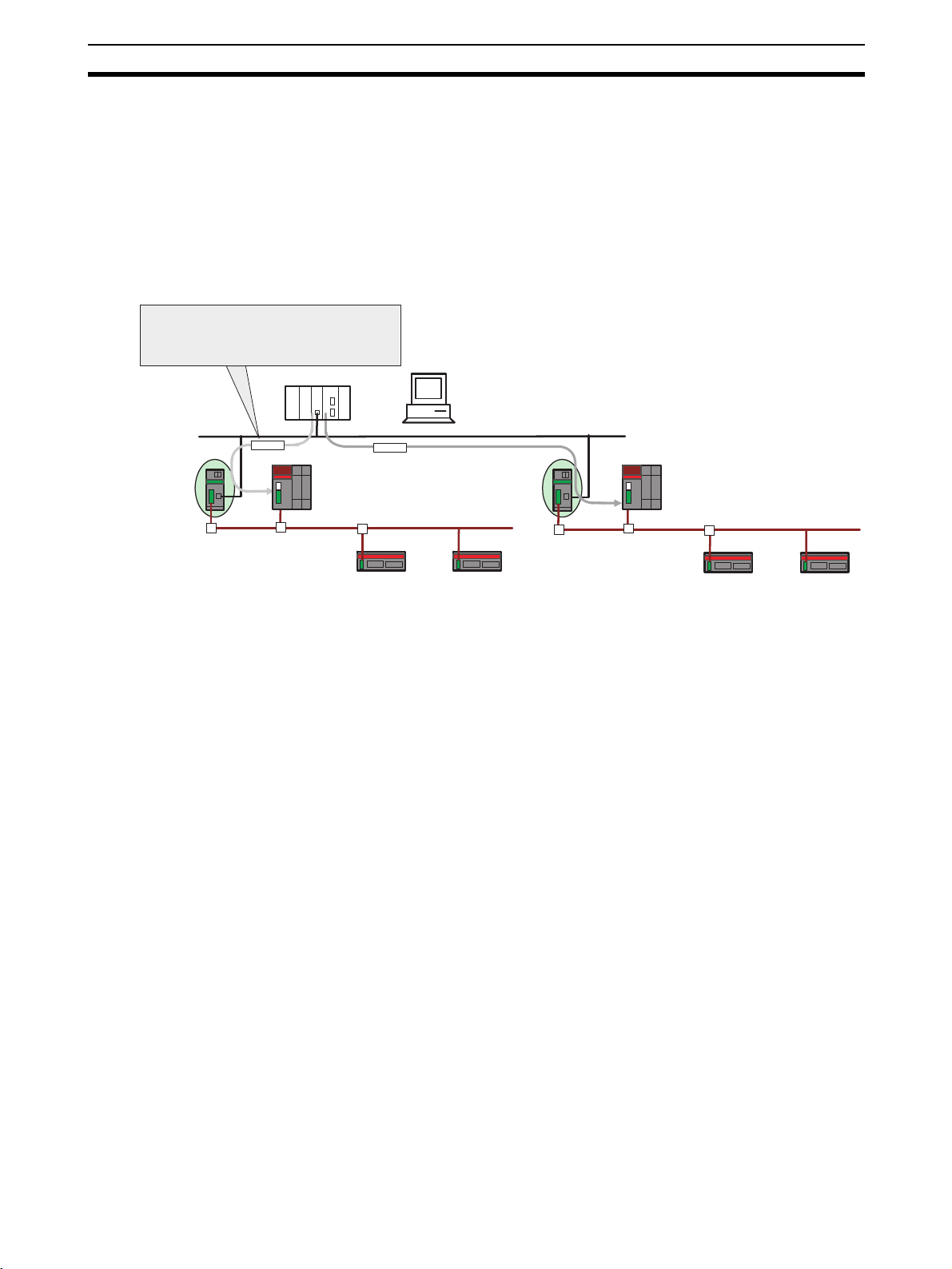
1-1-2 Monitoring DeviceNet or DeviceNet Safety Systems via Ethernet
from Controllers Made by Other Manufacturers
Devices on a DeviceNet or DeviceNet Safety network can be accessed from
general-purpose controllers (e.g., PLCs or computers) in an Ethernet network
using the UDP service.
This enables monitoring a DeviceNet or DeviceNet Safety control system via
Ethernet from a machine controller or monitor computer that does not support
a DeviceNet interface. This can be used to easily add a DeviceNet Safety control system to an existing system.
Safety controls can be monitored by accessing
devices on the DeviceNet Safety network using the
UDP service from a general-purpose controller on
the Ethernet network (e.g., a PLC or computer).
PLC (OMRON or other maker)
OR
Computer
ED Router
(NE1A-EDR01)
Command via UDP
Ethernet
Command via UDP
DeviceNet Safety
Socket service (UDP)
DeviceNet Safety
DST1-series Slaves
NE1A Safety Network Controller
DeviceNet Safety
DeviceNet Safety
DST1-series Slaves
3
Page 21
Nomenclature Section 1-2
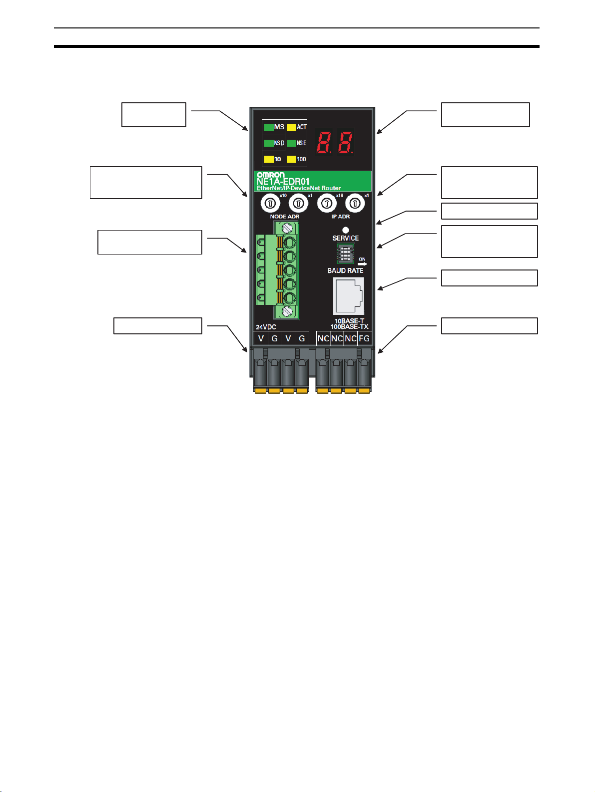
1-2 Nomenclature
The following illustration shows the part names of the ED Router.
Status indicators
DeviceNet node
address switches
DeviceNet
communications connector
Power supply connector
7-segment display
EtherNet/IP
IP address switches
Service switch
DeviceNet communications
baud rate switch
Ethernet connector
Ground connector
4
Page 22

Installation and Network Connections
This section describes how to install and connect the networks.
2-1 Installation. . . . . . . . . . . . . . . . . . . . . . . . . . . . . . . . . . . . . . . . . . . . . . . . . . . . 6
2-1-1 Requirements for Installation and Wiring . . . . . . . . . . . . . . . . . . . . 6
2-1-2 Mounting to the Control Panel . . . . . . . . . . . . . . . . . . . . . . . . . . . . . 6
2-1-3 ED Router Dimensions and Weight . . . . . . . . . . . . . . . . . . . . . . . . . 8
2-2 Wiring . . . . . . . . . . . . . . . . . . . . . . . . . . . . . . . . . . . . . . . . . . . . . . . . . . . . . . . 9
2-2-1 General Instructions on Wiring. . . . . . . . . . . . . . . . . . . . . . . . . . . . . 9
2-2-2 Wiring the Power Supply . . . . . . . . . . . . . . . . . . . . . . . . . . . . . . . . . 9
2-2-3 DeviceNet Wiring . . . . . . . . . . . . . . . . . . . . . . . . . . . . . . . . . . . . . . . 11
2-2-4 Ethernet (EtherNet/IP) Network Installation . . . . . . . . . . . . . . . . . . 12
2-3 Connecting to DeviceNet . . . . . . . . . . . . . . . . . . . . . . . . . . . . . . . . . . . . . . . . 16
2-3-1 Setting the DeviceNet Node Address . . . . . . . . . . . . . . . . . . . . . . . . 16
2-3-2 Setting the DeviceNet Baud Rate . . . . . . . . . . . . . . . . . . . . . . . . . . . 16
2-3-3 DeviceNet Node Address and Baud Rate Software Settings . . . . . . 17
2-4 Connecting to Ethernet (EtherNet/IP). . . . . . . . . . . . . . . . . . . . . . . . . . . . . . . 18
2-4-1 Setting the IP Address . . . . . . . . . . . . . . . . . . . . . . . . . . . . . . . . . . . 18
2-4-2 TCP/IP Configuration. . . . . . . . . . . . . . . . . . . . . . . . . . . . . . . . . . . . 19
2-5 ED Router Settings . . . . . . . . . . . . . . . . . . . . . . . . . . . . . . . . . . . . . . . . . . . . . 23
2-5-1 Setting the UDP Port Address and the Address Displayed at the ED
Router . . . . . . . . . . . . . . . . . . . . . . . . . . . . . . . . . . . . . . . . . . . . . . . . 23
SECTION 2
5
Page 23

Installation Section 2-1
2-1 Installation
2-1-1 Requirements for Installation and Wiring
Take the following into account during installation to improve the reliability of
the system and to fully utilize the system's capabilities.
Installation and
Storage Environment
Do not use or store the ED Router in the following locations.
• Locations subject to direct sunlight
• Locations subject to temperatures or humidity outside the ranges specified in the specifications
• Locations subject to condensation as the result of severe changes in temperature
• Locations subject to corrosive or flammable gases
• Locations subject to dust (especially iron dust) or salts
• Locations subject to water, oil, or chemicals
• Locations subject to shock or vibration
Take appropriate and sufficient measures when installing systems in the following locations. Inappropriate and insufficient measures may result in malfunction.
• Locations subject to static electricity or other forms of noise
• Locations subject to strong electromagnetic fields
• Locations subject to possible exposure to radioactivity
• Locations close to power supplies
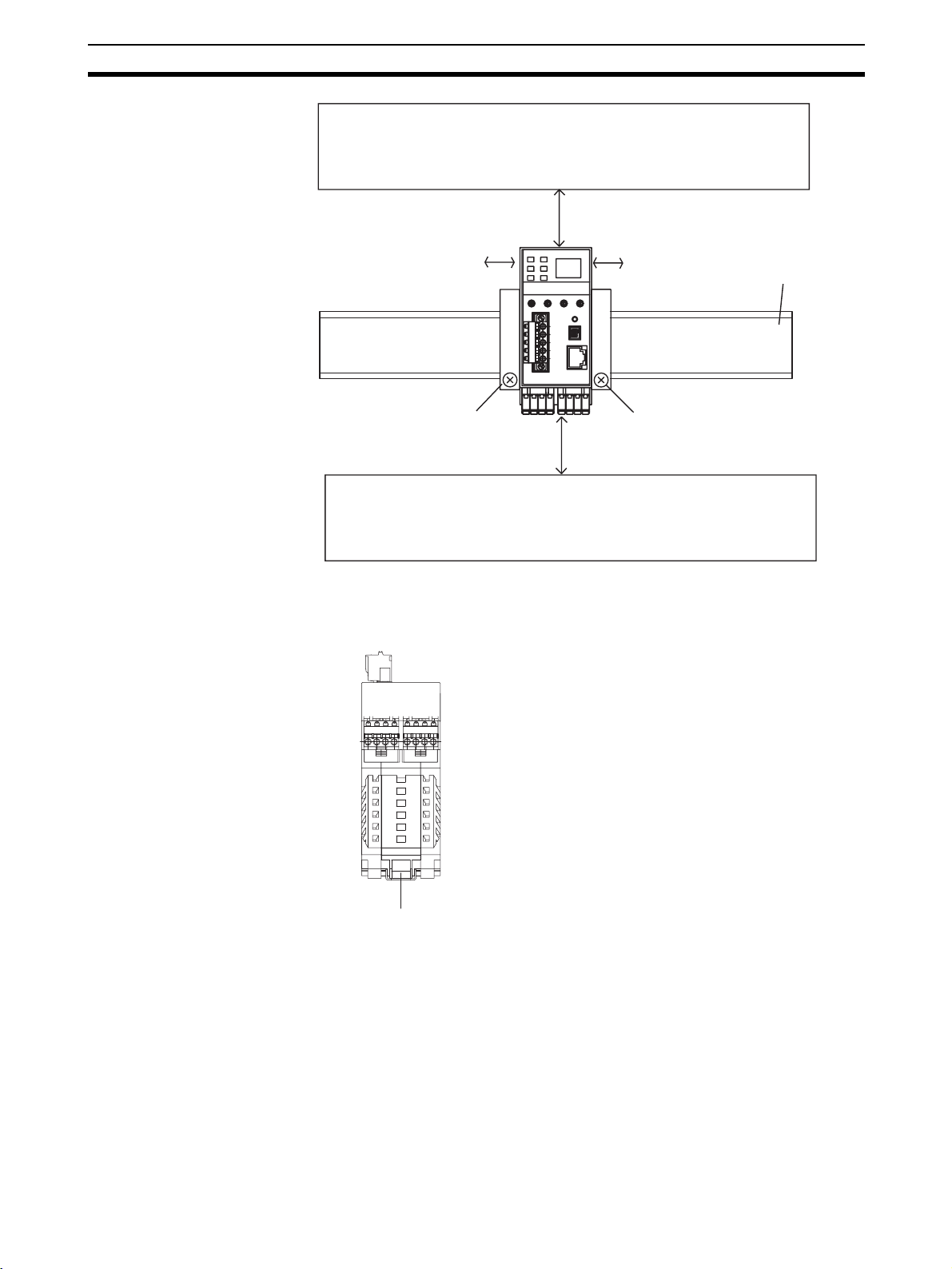
2-1-2 Mounting to the Control Panel
• Use the ED Router in an enclosure with IP54 degree of protection or
higher according to IEC/EN 60529.
• Use DIN Track (TH35-7.5/TH35-15 according to IEC 60715) to mount the
ED Router in the control panel. Mount the Router to the DIN Track using
PFP-M End Plates (not included with the ED Router) to prevent it from
falling off the DIN Track because of vibration.
• Provide sufficient space around the ED Router for ventilation and wiring,
at least 5 mm at the sides and at least 50 mm at the top and bottom.
• The ED Router can be mounted in any direction.
6
Page 24
Installation Section 2-1
k
s
Wiring duct
50 mm max.
Note The ED Router can be mounted only to a DIN Track. Do not screw the Router
DIN Track Mounting
Bracket Positions for the
ED Router
5 mm max. 5 mm max.
End Plate Model: PFP-M End Plate Model: PFP-M
50 mm max.
Wiring duct
to the control panel.
35-mm DIN Trac
DIN Track Mounting Bracket
7
Page 25
Installation Section 2-1
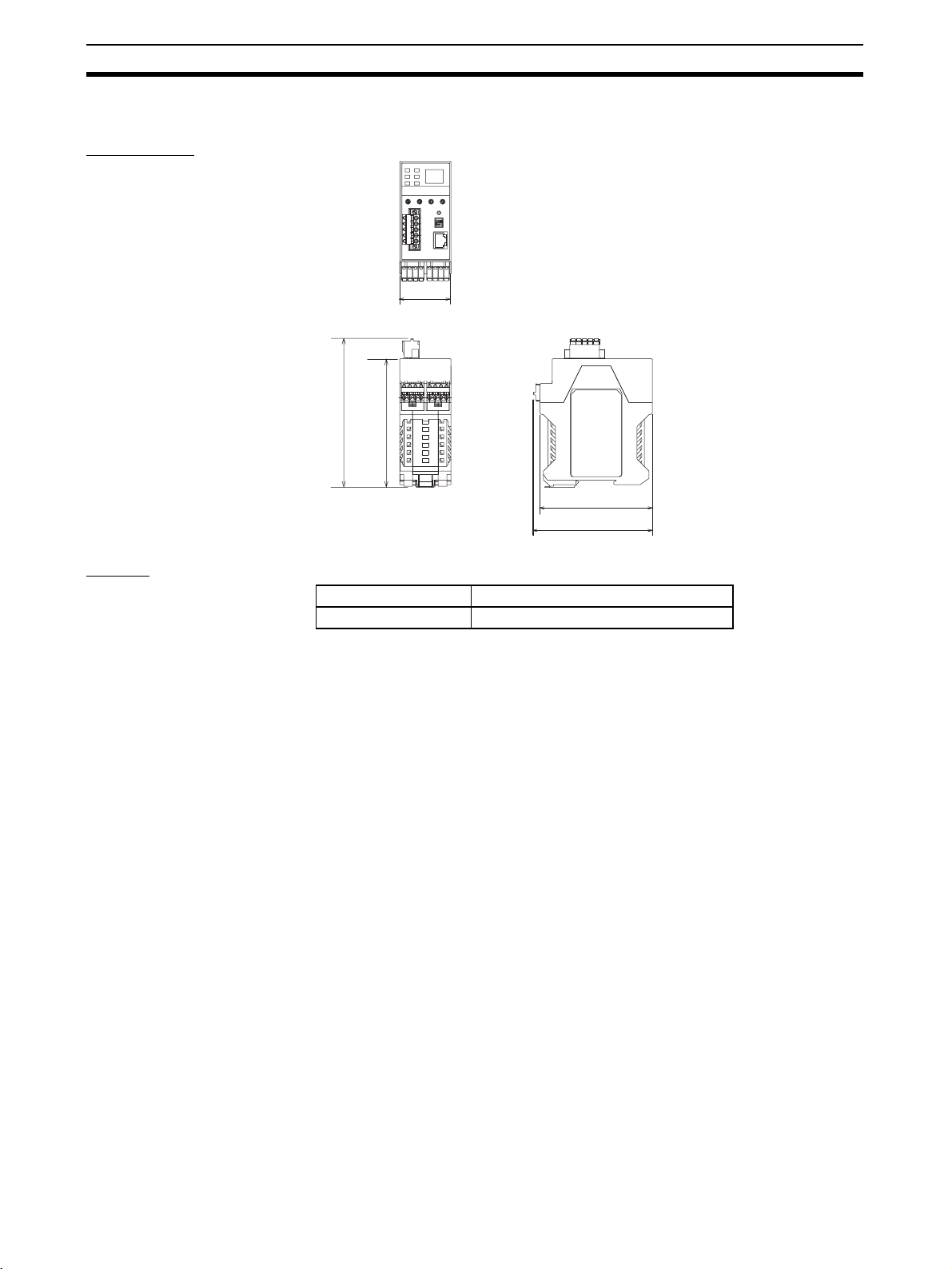
2-1-3 ED Router Dimensions and Weight
Dimensions
45.2
131.4
114.1
101.1
105.1
(Unit: mm)
Weight
Model Weight
NE1A-EDR01 220 g max.
8
Page 26

Wiring Section 2-2
2-2 Wiring
2-2-1 General Instructions on Wiring
Precaution:
• To prevent wire clippings from getting into the ED Router, do not remove
the label on the ED Router before wiring has been completed.
• After wiring has been completed, be sure to remove the label from the
Controller to enable heat dissipation for proper cooling.
• Disconnect the ED Router from the power supply before starting any wiring operations. Devices connected to the ED Router may operate unexpectedly if wiring is performed with the power supply connected.
• Be careful not to get your fingers caught when attaching connectors.
• Faulty wiring can result in a loss of safety functions. Be sure to perform
the wiring correctly, and check it before operation.
2-2-2 Wiring the Power Supply
Wire Sizes Use the following wires.
Solid wire
Stranded (flexible) wire
0.2 to 2.5 mm
0.34 to 1.5 mm
Stranded wires should be prepared by attaching ferrules with plastic
insulation collars (DIN 46228-4 standard compatible) before connecting them.
2
(AWG 24 to AWG 12)
2
(AWG 22 to AWG 16)
Recommended
Materials and Tools
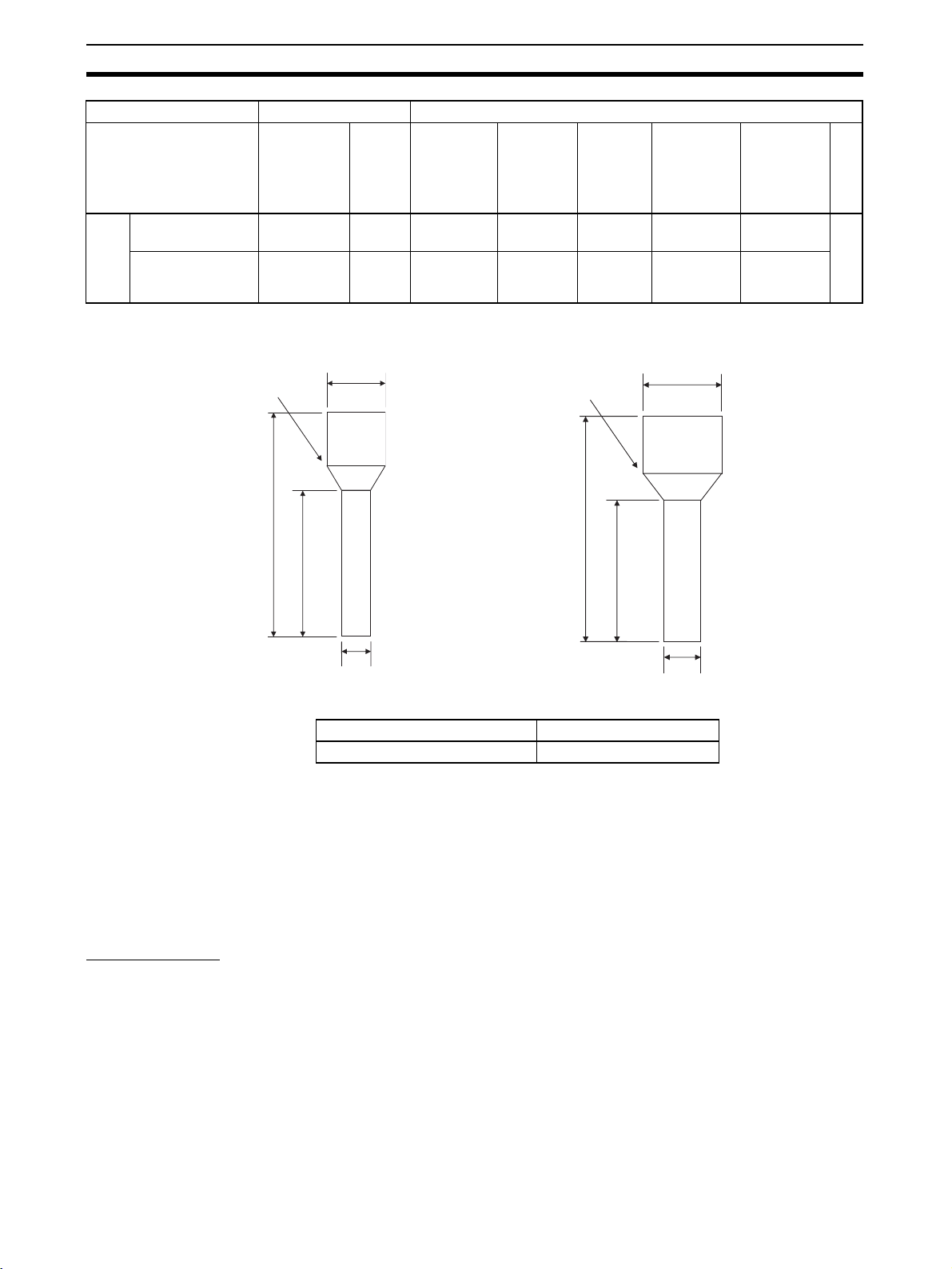
Insulated Pin Terminals Use a pin terminal with an insulated cover compliant with the DIN 46228-4
standard. Pin terminals similar in appearance but not compliant with the standard may not match the terminal block on the ED Router Controller. (The wiring dimensions are rough standards. Confirm the dimensions beforehand.)
Use wires of the same diameter if two-wire pin terminals are used.
Note (1) When wiring with pin terminals, be sure to insert pin terminals all the way
into the terminal block.
(2) When using two-wire pin terminals, use wires of the same diameter.
(3) When using two-wire pin terminals, insert the pin terminal so that metal
portion of the pin terminal is inserted straight into the terminal block, i.e.,
so that the long sides of the insulating cover are vertical.
Reference Specifications (Product Specifications for Phoenix Contact)
Model of pin terminal Wire dimensions Pin terminal specifications
Cross-
sectional
area of
conductor
2
(mm
AI 0,34-8TQ 0.34 22 10 12.5 8 0.8 2.0 *1
AI 0,5-10WH 0.5 20 10 16 10 1.1 2.5
AI 0,75-10GY 0.75 18 10 16 10 1.3 2.8
AI 1-10RD 1.0 18 10 16 10 1.5 3.0
terminals
One-wire pin
AI 1,5-10BK 1.5 16 10 18 10 1.8 3.4
AWG Stripped
)
length of
insulation
(mm)
Overall
length L1
(mm)
Length of
metal
part L2
(mm)
Inner
diameter of
conductor
D1 (mm)
Inner
diameter of
insulative
cover D2
(mm)
Dimensions
9
Page 27
Wiring Section 2-2
Model of pin terminal Wire dimensions Pin terminal specifications
AI-TWIN 2 x 0,7510GY
AI-TWIN 2 x 110RD
terminals
Two-wire pin
Cross-
sectional
area of
conductor
2
(mm
2 x 0.75 − 10 17 10 1.8 2.8/5.0 *2
2 x 1 − 10 17 10 2.05 3.4/5.4
*1: One-wire Pin Terminal *2: Two-wire Pin Terminal
Insulative cover
AWG Stripped
)
Dia. D2
length of
insulation
(mm)
Overall
length L1
(mm)
Insulative cover
Length of
metal
part L2
(mm)
Inner
diameter of
conductor
D1 (mm)
Dia. D2
Inner
diameter of
insulative
cover D2
(mm)
Dimensions
L1
L2
Dia. D1
L1
L2
Dia. D1
Terminal Crimping Tool
Manufacturer Model
Phoenix Contact CRIMPFOX UD6
Power Supply Selection
Use a DC power supply satisfying the following requirements.
• The secondary circuits of the DC power supply must be isolated from the
primary circuit by double insulation or reinforced insulation.
• The DC power supply must satisfy the requirements for class 2 circuits or
limited voltage/current circuits defined in UL 508.
• The output hold time must be 20 ms or longer.
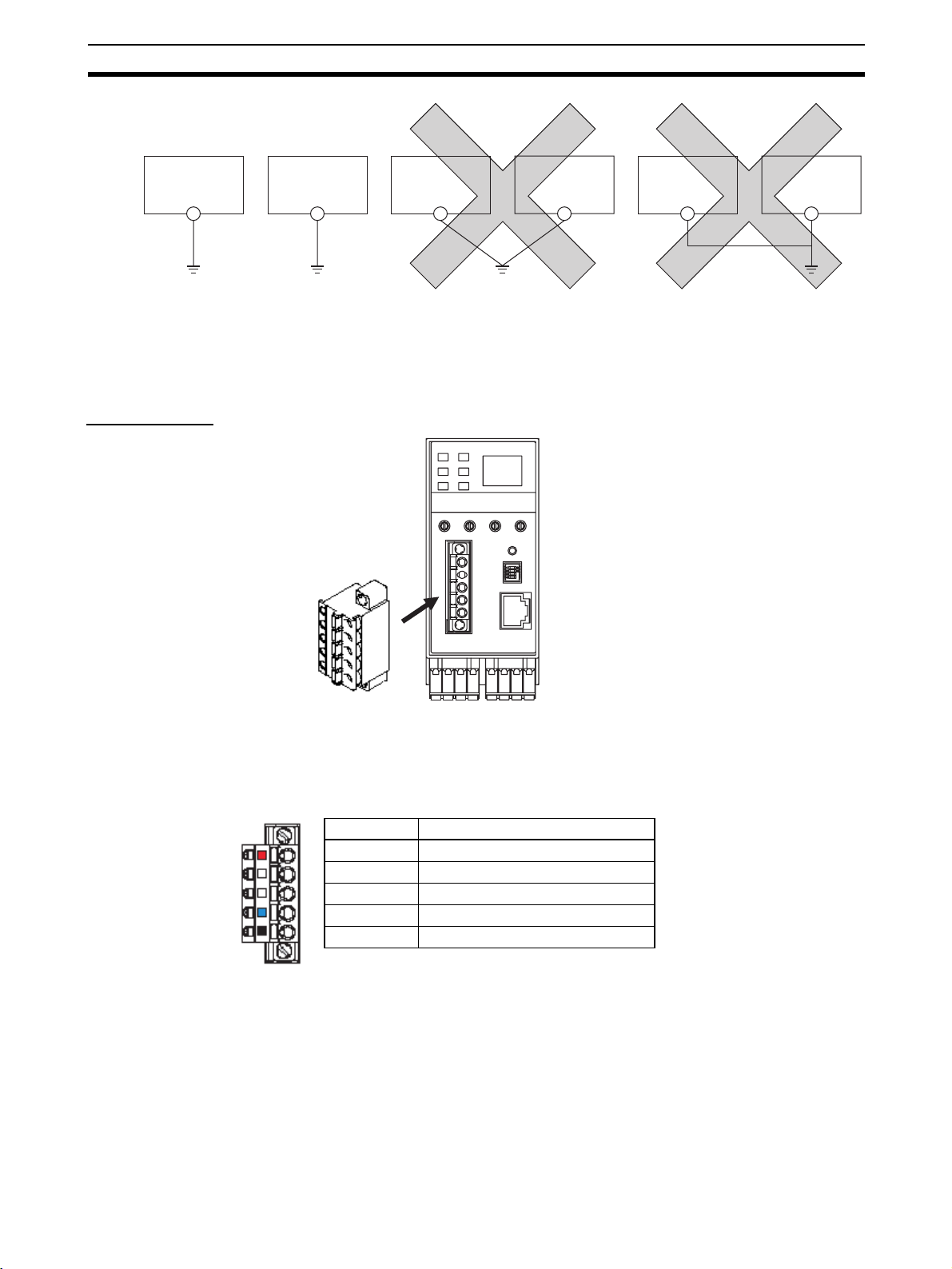
Ground Wiring The ED Router has a functional ground terminal. To prevent electric shock or
malfunctioning due to excessive noise, use an independent ground wire
(2 mm min.) with a maximum ground resistance of 100
ground wire should be no more than 20 m. To avoid grounding problems, do
not share the ground wiring with other devices or connect it to the building
structure. To further reduce noise, connect a noise filter.
Ω. The length of the
10
Page 28
Wiring Section 2-2
ED Router
Ground with max.
resistance of
100-Ω
Independent ground: Correct
Other devices
ED Router
Other devices
Shared ground: Incorrect
ED Router
Other devices
Note Ground correctly to avoid malfunctioning due to noise.
2-2-3 DeviceNet Wiring
Wiring Cables Wire the DeviceNet communications cable as shown in the following diagram.
IMPORTANT
Stickers are placed on the communication connectors based on the color of
each communications wire. By matching the communications wire colors with
the connector sticker colors, you can check to see if wires are in the correct
locations. The colors of the wires are as follows:
Color Description
Red V+
White Signal (CAN H)
-Drain
Blue Signal (CAN L)
Black V−
• Turn OFF the power supply to the NE1A-series Controller, to all nodes on
the network, and to communications lines before starting any wiring operations.
• Tighten the DeviceNet connector to the appropriate torque (0.25 to
0.3 N·m).
• Separate the DeviceNet communications cables from high-voltage/current
lines.
11
Page 29

Wiring Section 2-2
Note Refer to the DeviceNet Operation Manual (W267) for further information on
wiring.
2-2-4 Ethernet (EtherNet/IP) Network Installation
Basic Installation
Precautions
Recommended
Network Devices
Part Maker Model number Inquires
Switching Hub Cisco Systems, Inc. Consult the manufacturer. Cisco Systems, Inc. Main Corporate HQ
Contec USA, Inc. Consult the manufacturer. CONTEC USA Inc.
Phoenix Contact Consult the manufacturer. Phoenix Contact USA Customer Service
Tw is t e d- p ai r
cable
Connectors
(Modular plug)
Boots Tsuko Company MK boot (IV) LV Tsuko Company Japan Headquarters
100BASE-TX
Fujikura F-LINK-E 0.5mm × 4P Fujikura America, Inc.
EtherNet/IP compliant cable ---
STP Plug
Panduit Corporation MPS588 Panduit Corporation US Headquarters
• Take the greatest care when installing the Ethernet System, being sure to
follow ISO 8802-3 specifications. You must obtain a copy of these specifications and be sure you understand them before attempting to install an
Ethernet System.
• Unless you are already experienced in installing communications systems, we strongly recommend that you employ a professional to install
your system.
• Do not install Ethernet equipment near sources of noise. If a noisy environment is unavoidable, take adequate measures against noise interference, such as installing network components in grounded metal cases or
using optical cable in the system.
The following table shows the devices recommended for use with the ED
Router.
Precautions
Precautions on Laying
Twisted-pair Cable
Note • Ask the switching hub manufacturer for setting procedures for the switch-
ing hub.
• Install the switching hub so that its environmental resistance capabilities
are not exceeded.
Ask the switching hub manufacturer for information on the environmental
resistance of the switch hub.
• Noise resistance may be reduced by ground loops, which can occur due
to improper shield connections and grounding. Ground the shield at one
location, as shown in the following diagram.
• Do not connect the shield to the ED Router connector.
• If a cable connects two hubs, connect the shields at only one end.
12
Page 30

Wiring Section 2-2
Hub Hub
Connector Connector Connector Connector Connector
GR GR
STP
(Shield)
Connect shield.
Do not connect shield.
STP
(Shield)
STP
(Shield)
ED Router
Connector
ED Router
Connector
FG
terminal
FG
terminal
• Press the cable connector in firmly until it locks into place at both the
switching hub and the ED Router.
• Do not lay the twisted-pair cable together with high-voltage lines.
• Do not lay the twisted-pair cable near devices that generate noise.
• Do not lay the twisted-pair cable in locations subject to high temperatures
or high humidity.
• Do not lay the twisted-pair cable in locations subject to excessive dirt and
dust or to oil mist or other contaminants.
Switching Hub Installation
Environment Precautions
Switching Hub
Connection Methods
• Do not ground the switching hub in the same location as a drive-system
component such as an inverter.
• Always use a dedicated power supply for the switching hub’s power supply. Do not use the same power supply used for other equipment, such as
an I/O power supply, motor power supply, or control power supply.
• Before installation, check the switching hub’s environment-resistance
specifications, and use a switching hub appropriate for the ambient conditions. Contact the switching hub manufacturer for details on switching
hub’s environment-resistance specifications.
• Connect two hubs to each other as follows: Connect an MDI port to an
MDI-X port with a straight cable; connect two MDI ports with a cross
cable; and connect two MDI-X ports with a cross cable.
Note It is very difficult to distinguish cross cables and straight cables by
appearance. Incorrect cables will cause communications to fail. We
recommend using cascade connections with straight cables whenever possible.
MDI-X port
(cross)
MDI ports
Switching
Hub
Switching
Hub
Switching
Hub
: Straight cable
: Cross cable
Switching
Hub
• Some switching hubs can automatically distinguish between MDI and
MDI-X. When this kind of switching hub is being used, straight cable can
be used between switching hubs.
13
Page 31

Wiring Section 2-2
Note Adjust the ED Router link settings to match the communications settings of
the connected switching hub. If the settings do not match, the link will become
unstable and prevent normal communications. The following table shows the
allowed settings for each switching hub communications mode.
ED Router
Switching hub setting
Auto-negotiation Best --- OK --- OK
10 Mbps
(fixed)
100 Mbps
(fixed)
Full duplex --- OK --- --- ---
Half duplex OK --- OK --- ---
Full duplex --- --- --- Best ---
Half duplex OK --- --- --- OK
Auto-
negotiation
10 Mbps (fixed) 100 Mbps (fixed)
Full
duplex
Half
duplex
Full
duplex
Half
duplex
Best = Recommended; OK = Allowed; --- = Not allowed.
Ethernet Connectors The following standards and specifications apply to the connectors for the
Ethernet twisted-pair cable.
• Electrical specifications: Conforming to IEEE802.3 standards.
• Connector structure: RJ45 8-pin Modular Connector
(conforming to ISO 8877)
Connector pin Signal name Abbr. Signal direction
1 Transmission data + TD+ Output
2 Transmission data – TD– Output
3 Reception data + RD+ Input
4 Not used. --- ---
5 Not used. --- ---
6 Reception data – RD– Input
7 Not used. --- ---
8 Not used. --- ---
Hood Frame ground FG ---
Note The ED Router Ethernet port has auto MDI/MDI-X functionality, so either a
Connecting the Cable
!Caution Turn OFF the ED Router power supply before connecting or disconnecting
!Caution Allow enough space for the bending radius of the twisted-pair cable as shown
straight or cross cable can be used.
twisted-pair cable.
in below.
14
Page 32

Wiring Section 2-2
ED Router
35 mm
1,2,3... 1. Lay the twisted-pair cable.
2. Connect the cable to the switching hub. Be sure to press in the cable until
it locks into place. This procedure should only be performed by qualified
personnel.
3. Connect the twisted-pair cable to the connector on the ED Router.
Be sure to press the connectors (both the switching hub side and Ethernet
side) until they lock into place.
15
Page 33

Connecting to DeviceNet Section 2-3
2-3 Connecting to DeviceNet
2-3-1 Setting the DeviceNet Node Address
Set the DeviceNet node address using the rotary switches (NODE ADR) on
the front of the ED Router.
Method Two-digit decimal number
Range 0 to 63
Note The node address is set to 63 at the factory.
Any node address in the setting range can be used as long as the same
address is not used by another node. If a value between 64 and 99 is set on
the rotary switches, the node address can be set using a software setting on
the Network Configurator.
IMPORTANT
• Turn OFF the power to the ED Router before setting the rotary switches.
• Do not change the rotary switches while the power is ON.
• A node address duplication error will occur if the same address is set for
more than one node. Communications will not start if this error occurs.
Note • Use a small flat-blade screwdriver to set the rotary switches, being careful
not to scratch them.
• Refer to 2-3-3 DeviceNet Node Address and Baud Rate Software Settings
for software setting procedures.
2-3-2 Setting the DeviceNet Baud Rate
The DeviceNet baud rate is set using the DIP switch on the front of the ED
Router. The baud rate settings are shown in the following table:
1 2 3 4
OFF OFF OFF OFF
ON OFF OFF OFF 250 kbit/s
OFF ON OFF OFF 500 kbit/s
ON ON OFF OFF Software setting
ON or
OFF
ON or
OFF
Note The baud rate is set to 125 kbit/s at the factory.
Note Refer to 2-3-3 DeviceNet Node Address and Baud Rate Software Settings for
software setting procedures.
ON or
OFF
ON or
OFF
Pin Baud rate
125 kbit/s
ON OFF
ON or
OFF
ON Automatic baud rate
detection
16
Page 34

Connecting to DeviceNet Section 2-3
2-3-3 DeviceNet Node Address and Baud Rate Software Settings
Use the following procedure to set the ED Router DeviceNet node address
and baud rate from the Network Configurator.
1,2,3... 1. Select Programs - OMRON Network Configurator for DeviceNet Safety
- Network Configurator from the Start Menu. The Network Configurator
will be started.
2. Connect the Network Configurator online. (First set the interface with Op-
tion - Select Interface, and then select Network - Connect.)
3. Select DeviceNet in the Network Configuration Window. (For example,
click the DeviceNet_1 Ta b. )
4. Select Tool - Node Address/Baud Rate Setting.
The following dialog box will be displayed.
5. Specify the present node address of the target ED Router in the Ta r ge t
Node Address Field.
6. To change the node address, specify a new node address in the New Node
Address Field and click the Change Button.
The node address of the ED Router will be changed.
7. To change the baud rate, select the rate in the New Baud Rate Field and
click the Change Button.
The baud rate of the ED Router will be changed.
17
Page 35

Connecting to Ethernet (EtherNet/IP) Section 2-4
2-4 Connecting to Ethernet (EtherNet/IP)
2-4-1 Setting the IP Address
This section describes methods for setting the IP address for the ED Router.
Method 1: The default IP address is 192.168.250.IP_address_switch_set
value.
The IP address is set with the rotary switches on the front of the
ED Router (IP ADR).
→ This method can be used to make a temporary or preliminary
connection to the Ethernet.
In this case, leave the TCP/IP Configuration setting at its
default value.
Method 2: Setting the TCP/IP Configuration from the Network Configura-
tor:
→ To set a particular local IP address, use the Network Configu-
rator.
The methods for setting the ED Router IP address are described below.
Method 1: Using the Default IP Address (192.168.250.IP_address_switch_set value)
The default IP address for the ED Router is
192.168.250.IP_address_switch_set value. The IP address switch is used to
set the IP address host ID.
IP address = 192.168.250.
The host IC can be changed with the IP address switch. If 00 or FF is set, 01
will be used as the host ID.
The TCP/IP settings will be in the following default settings.
Setting Operating status
IP address 192.168.250.IP_address_switch_set value
Subnet mask 255.255.255.0 (class C mask)
Default gateway None (IP routing disabled)
Preferred DNS server None
Alternate DNS server None
Host name None
Domain name None
Baud rate Auto-detect
IP_address_switch_set value
Method 2: Setting the TCP/IP Configuration from the Network Configurator
With this method, set the TCP/IP configuration, including the IP address, from
the Network Configurator.
18
Page 36

Connecting to Ethernet (EtherNet/IP) Section 2-4
2-4-2 TCP/IP Configuration
This section describes the TCP/IP-related settings, such as the ED Router
local IP address and subnet mask. Use the Network Configurator to make
these settings. The settings are stored in the ED Router non-volatile memory.
Note (1) With the default settings, the IP address will be 192.168.250.1 if 00 or FF
is set.
(2) If the IP address switch is set to a value other than 00 or FF, the switch
setting will be used for the rightmost bit of the IP address. To use the value set from the Network Configurator, set the IP address switch to 00 or
FF.
(3) To use the BOOTP server, set the IP address switch to 00 or FF.
Making TCP/IP
Settings with the
Network Configurator
1,2,3... 1. Select Programs - OMRON Network Configurator for DeviceNet Safety
- Network Configurator from the Start Menu. The Network Configurator
will be started.
2. Connect the Network Configurator online. (First set the interface with Op-
tion - Select Interface, and then select Network - Connect.)
3. Select EtherNet/IP in the Network Configuration Window. (For example,
click the EtherNet/IP Tab. )
4. Select Tools - Setup TCP/IP Configuration. The Setup TCP/IP Configuration Dialog Box will be displayed.
The settings are all at their default values.
19
Page 37

Connecting to Ethernet (EtherNet/IP) Section 2-4
5. For the Target IP Address, specify the present IP address of the ED Router
for which the IP address is to be set.
6. To change the IP address, select Use the following IP address and then set
the new IP address.
20
7. Click the Set to the Device Button.
The ED Router will restart automatically.
8. Check the 7-segment display on the ED Router.
If the 7-segment display is tested again after it goes OFF, and finally displays the DeviceNet node address, it indicates that the ED Router has recognized the new TCP/IP Configuration settings.
Note (1) The ED Router will restart automatically when the TCP/IP Configuration's
IP address parameters are downloaded to the ED Router from the Network Configurator. The ED Router must restart to enable the parameter
settings. Download the TCP/IP Configuration's IP address parameters
only after verifying that restarting the Unit will not cause any problems in
the system.
(2) The IP address can be checked on the 7-segment display by pressing the
ED Router service switch for 1 s or longer and then releasing it.
(3) With an ED Router parameter setting, the value normally displayed on the
7-segment display can be changed to the rightmost byte of the IP address.
Page 38

Connecting to Ethernet (EtherNet/IP) Section 2-4
TCP/IP Setting Details The ED Router TCP/IP Configuration settings include the following settings.
• IP address
• Subnet mask
• Default gateway
• Preferred DNS server
• Alternate DNS server
• Domain name
• Link setting
IP Address Sets the ED Router local IP address.
Set the local IP address in this TCP/IP Configuration when not using the
default IP address (default IP address =
192.168.250.IP_address_switch_set_value).
Subnet Mask For the subnet mask, all bits corresponding to the bits in the IP address used
as either the net number or the subnet number are set to 1, and the bits corresponding to the host number are set to 0.
If no subnet mask is set, or if an illegal value is set, the following values will be
used depending on the IP address class.
Class Subnet mask
Class A 255.0.0.0
Class B 255.255.0.0
Class C 255.255.255.0
With the default setting (0.0.0.0), a subnet mask corresponding to the IP
address class is used.
Default Gateway Sets the default gateway’s IP address.
This setting is not required when the default gateway is not being used.
Preferred DNS Server
and Alternate DNS
Server
When accessing another node from the ED Router using the host name, the
DNS server searches for the other node's IP address from the other node's
host name to the DNS server. These settings register the IP addresses of the
preferred and alternate DNS servers that will perform the search. At this time,
the NEIA Series and the ED Router are not equipped with any functions that
require a DNS server, so these settings are not used. Even if the settings are
made, however, they will not cause faulty operation.
Domain Name Sets the domain name of the domain to which the ED Router belongs.
The ED Router does not use a domain name in actual communications.
Link Setting Sets the communications baud rate.
Setting Meaning
Auto (default) The baud rate with the switching hub is detected automati-
10 Mbps, Half Duplex Operates in 10BASE-T, half duplex.
10 Mbps, Full Duplex Operates in 10BASE-T, full duplex.
100 Mbps, Half Duplex Operates in 100BASE-TX, half duplex.
100 Mbps, Full Duplex Operates in 100BASE-TX, full duplex.
cally. If possible, the Unit operates in 100BASE-T (full
duplex).
21
Page 39

Connecting to Ethernet (EtherNet/IP) Section 2-4
Note Adjust the ED Router link settings to match the communications settings of
the connected switching hub. If the settings do not match, the link will become
unstable and prevent normal communications. The following table shows the
allowed settings for each switching hub communications mode.
ED Router
Switching hub setting
Auto-negotiation OK --- OK --- OK
10 Mbps
(fixed)
100 Mbps
(fixed)
Full duplex --- OK --- --- ---
Half duplex OK --- OK --- ---
Full duplex --- --- --- OK ---
Half duplex OK --- --- --- OK
Auto-
negotiation
10 Mbps (fixed) 100 Mbps (fixed)
Full
duplex
Half
duplex
Full
duplex
duplex
OK = Allowed; --- = Not allowed.
Half
22
Page 40

ED Router Settings Section 2-5
2-5 ED Router Settings
2-5-1 Setting the UDP Port Address and the Address Displayed at the
ED Router
Use the Network Configurator to set the address displayed on the ED Router
7-segment display and to set the UDP port address.
■ Setting the Address Displayed at the ED Router
Select either the EtherNet/IP IP address or the DeviceNet node address as
the address to be displayed on the ED Router 7-segment display when the
status is normal.
■ Setting the UDP Port Address
Select a number from 1,024 to 65,535 for the UDP port to be used for device
access by UDP.
1,2,3... 1. Select Programs - OMRON Network Configurator for DeviceNet Safety
- Network Configurator from the Start Menu. The Network Configurator
will be started.
2. Connect the Network Configurator online. (First set the interface with Op-
tion - Select Interface, and then select Network - Connect.)
3. In the Network Configuration Window, double-click the ED Router that is to
be set. The following dialog box will be displayed.
4. Set the address to be displayed at the ED Router, or set the UDP port address.
• To set the address to be displayed at the ED Router, click 0001 Display
Mode and select Low byte of Ethernet IP address (EtherNet/IP IP address) or DeviceNet MAC ID (DeviceNet node address).
• To set the UDP port address, click 0002 UDP Port No. and input a
number from 1,024 to 65,535.
5. After making the setting, click the OK Button.
6. In the Network Configuration Window, select the ED Router. Right-click
and select Parameter - Download. After the parameters have been downloaded, the ED Router will be automatically reset and it will then operate
using the new parameters.
23
Page 41

ED Router Settings Section 2-5
24
Page 42

SECTION 3
Status Indicators and Troubleshooting
This section describes how to interpret the status indicators and how to troubleshoot problems that may occur with the ED
Router.
3-1 Status Indicators . . . . . . . . . . . . . . . . . . . . . . . . . . . . . . . . . . . . . . . . . . . . . . . 26
3-1-1 Overview. . . . . . . . . . . . . . . . . . . . . . . . . . . . . . . . . . . . . . . . . . . . . . 26
3-1-2 Seven-segment Display. . . . . . . . . . . . . . . . . . . . . . . . . . . . . . . . . . . 27
3-2 Troubleshooting . . . . . . . . . . . . . . . . . . . . . . . . . . . . . . . . . . . . . . . . . . . . . . . 29
3-2-1 ED Router Errors and Error Processing . . . . . . . . . . . . . . . . . . . . . . 29
3-3 Error History . . . . . . . . . . . . . . . . . . . . . . . . . . . . . . . . . . . . . . . . . . . . . . . . . . 32
3-3-1 Error History Table . . . . . . . . . . . . . . . . . . . . . . . . . . . . . . . . . . . . . . 32
3-3-2 Error History Code List . . . . . . . . . . . . . . . . . . . . . . . . . . . . . . . . . . 34
25
Page 43

Status Indicators Section 3-1
3-1 Status Indicators
This section describes the ED Router status indicators (LEDs).
3-1-1 Overview
ED Router and network status are displayed on the following status indicators.
• MS (Module Status): Displays the status of the ED Router.
• NS E (Network Status, EtherNet/IP): Displays the status of the EtherNet/
IP network.
• NS D (Network Status, DeviceNet): Displays the status of the DeviceNet
network.
• 10: Lit when Ethernet is connected by 10Base-T.
• 100: Lit when Ethernet is connected by 100Base-T.
• ACT: Lit when Ethernet communications are detected.
The following table describes the MS, NS E, and NS D indicators in detail.
Indicator name Color Status Meaning
MS
(module status)
NS E, NS D
(Network Status)
Green Operation status
Red Fatal error (Critical fault)
An ED Router failure has occurred, and recovery is not possible. ED Router
operation stops and the NS E and NS D indicators turn OFF.
• ED Router failure.
Fatal error (Abort)
One of the following recoverable errors has occurred. Message communica-
tions routing is enabled.
• Switch changed during operation (failure, unintended operation, etc.)
• Setting error due to power interruption while making settings
- Power is not being supplied.
Green While online, at least one CIP connection is established.
While online, not even one CIP connection is established.
Red Communications are not possible.A non-recoverable communications error
was detected in the network.
• DeviceNet bus OFF error
• DeviceNet node address duplication error
• EtherNet/IP IP address duplication error
A recoverable communications error was detected in the network.
• DeviceNet network power supply error
• DeviceNet communications timeout error
• BOOTP server connection error
• DeviceNet node address switch setting changed after startup.
• EtherNet/IP IP address switch setting changed after startup.
• DeviceNet node baud rate switch setting changed after startup.
- Not connected online.
26
: ON : Flashing : OFF
Page 44

Status Indicators Section 3-1
3-1-2 Seven-segment Display
This section describes the meanings of the 7-segment display.
Normal Status When no error has occurred and communications are enabled, the ED Router
DeviceNet node address is displayed as the initial status on the 7-segment
display.
• Display Example: When the Node Address Is 01
The rightmost byte of the EtherNet/IP IP address can be displayed by a setting from the Network Configurator.
Error Status When an error occurs, the error code is displayed following Er. If multiple
errors occur, the error codes are displayed in order.
• Display Example: When the Error Codes Are d6 and E0
1000 ms Not lit
100 ms.
(Error) (Error)
1000 ms
for
(Error code) (Error code)
Not lit
for
100 ms.
1000 ms
Not lit
for
100 ms.
Not lit
for
300 ms.
Displaying the EtherNet/IP IP Address and the DeviceNet Node Address
The EtherNet/IP IP address and the DeviceNet node address can be displayed on the 7-segment display by pressing the service switch for 1 s or
longer before releasing it.
• Display Example: EtherNet/IP IP Address
• Display Example: EtherNet/IP IP Address when BOOTP Is Set
• Display Example: DeviceNet Node Address
27
Page 45

Status Indicators Section 3-1
• Display Example: When IP Address is 192.200.200.2
The IP address moves across the display from right to left.
300 ms 300 ms 300 ms 300 ms Not lit
for
50 ms.
Not lit
for
50 ms.
Not lit
for
50 ms.
Not lit
for
500 ms.
Not lit
for
50 ms.
Note Errors are indicated by combining the MS indicator, NS indicator, and the 7-
segment display. For further details on specific meanings, refer to 3-2 Trouble-
shooting.
28
Page 46

Troubleshooting Section 3-2
3-2 Troubleshooting
3-2-1 ED Router Errors and Error Processing
Indicators/Display Error Cause ED Router
MS NS D NS E 7-seg-
Hardware-related Errors
Lit red Not lit Not lit Not lit
Flashing
red
Flashing
red
Communications-related Error
--- --- --- --- Illegal mes-
Ethernet Communications-related Errors
--- --- --- E1 Link OFF
--- --- Not lit E3 Server con-
--- --- Lit red F0 IP address
--- --- E9 Memory
--- Not lit F4 Ethernet
ment
or H3
System error ED Router fail-
ure
access error
communications controller error
sage discarded.
error
nection error
duplication
error
An error
occurred in
involatile memory in the Unit.
An Ethernet
communications
controller error
occurred.
The message
was discarded
due to illegal
packet communications.
No link was
detected
between switching hubs.
An error
occurred
between the ED
Router and the
BOOTP server.
• There is no
response from
the BOOTP
server.
• The IP address
received from
the BOOTP
server is illegal.
The ED Router
IP address is the
same as the IP
address set for
another device.
Operation stops. None
Operation stops. 0602
Ethernet communications stop.
Operation stops. 0118 Check the system communi-
Operation continues after error
recovery.
Ethernet communications stop until
a legal IP address
can be received.
Ethernet communications stop.
operation
Error
code
(hex)
or
0601
020F
03D3 Check the Ethernet cable,
03C4 Check the BOOTP server.
0211 Check the IP address set-
Countermeasures
Replace the ED Router if the
problem recurs after restarting.
cations status.
hub, etc.
tings and the network connections.
29
Page 47

Troubleshooting Section 3-2
Indicators/Display Error Cause ED Router
MS NS D NS E 7-seg-
DeviceNet Communications-related Errors
--- Lit red --- F0 Node
--- Lit red --- F1 Bus OFF
--- Not lit --- E0 DeviceNet
--- Flash-
Settings-related Error
Flashing
red
Flashing
red
Flashing
red
Flashing
red
ing
red
--- --- F2 Ethernet
Flashing
red
--- Flash-
Flashing
red
--- E2 DeviceNet
--- C8 DeviceNet
ing
red
--- C8 Baud rate
ment
address
duplication
error
error
network
power supply error
communications timeout
error
basic setting
error
node
address setting changed
during operation
C8 IP address
setting
changed during operation
setting
changed during operation
The ED Router
DeviceNet node
address is the
same as the
node address
set for another
device.
A DeviceNet bus
OFF error was
detected.
The DeviceNet
network power
supply is OFF.
Data could not
be sent in
DeviceNet for
1 s or longer.
An error
occurred in the
data set for the
TCP/IP Configuration.
The node
address switch
setting was
changed during
operation.
The IP address
switch setting
was changed
during operation.
The baud rate
switch setting
was changed
during operation.
DeviceNet operation stops.
DeviceNet communications stop.
DeviceNet communications stop
until the network
power supply is
restored.
DeviceNet communications stop
until normal communications are
restored.
Operation continues, using the
default values for
the TCP/IP Configuration.
Operation continues, using the
value from before
the change.
Operation continues, using the
value from before
the change.
Operation continues, using the
value from before
the change.
operation
Error
code
(hex)
0211 Check the node addresses
0340 Check the DeviceNet net-
0341 Check the DeviceNet net-
0342 Check the following items:
03D0 Check the Ethernet settings.
0214 Check the node address
0214 Check the IP address switch
0214 Check the baud rate switch
Countermeasures
and the network connections
for all devices on the
DeviceNet network.
work for short-circuiting and
check the baud rate.
work power supply and the
communications cable connections.
• Is the baud rate the same
for each node?
• Are the cable lengths (main
and branch lines) correct?
• Are any cables disconnected or loose?
• Is terminating resistance
connected at both ends of
the main line?
switch setting. If the error
persists after the correct setting has been made, replace
the ED Router.
setting. If the error persists
after the correct setting has
been made, replace the ED
Router.
setting. If the error persists
after the correct setting has
been made, replace the ED
Router.
30
Page 48

Troubleshooting Section 3-2
Indicators/Display Error Cause ED Router
MS NS D NS E 7-seg-
Flashing
red
Flashing
red
--- Flashing
red
--- --- E8 Device
ment
F3 Invalid IP
address setting
parameter
error
The IP address
is set to be
received from
the BOOTP
server, but the IP
address switch
is set for a value
other than 00 or
FF.
An error
occurred in the
parameters
downloaded
from the Network Configurator.
Operation continues, using the
value set by the IP
address switch.
Operation continues, using the
default setting.
operation
Error
code
(hex)
0214 Check the IP address switch
021A Make the settings again from
Countermeasures
setting and the configuration, and make the settings
again.
the Network Configurator. If
the error persists after the
correct settings have been
made, replace the ED
Router.
31
Page 49

Error History Section 3-3
3-3 Error History
The error history records errors that the ED Router detects, along with the
total operating time of the ED Router. The results recorded in the error history
can then be read or cleared from the Network Configurator.
Depending on the contents of the error history, some parts are cleared and
some are not cleared when the CPU Unit power is turned OFF or reset.
3-3-1 Error History Table
Error History Table When an error is detected in the ED Router, the error is recorded in the error
history table in the RAM of the ED Router. The error history contains one
record per error and can hold up to 64 records. If the error history table
already contains 64 records, the oldest record is deleted and the new error
data is stored.
The following information is stored in the error history table:
• Time that error occurred (total ED Router operating time)
• Error information
• Detailed information
Error History Saving
Area
Reading and Clearing
the Error History
Table
Note The total operating time of the ED Router is recorded as the accumulated time
The description of an error is recorded in the error history in the RAM of the
ED Router, and if the error is critical, it is also saved in the nonvolatile memory. The error history recorded in nonvolatile memory is retained even when
the power supply of the ED Router is not supplied or restarted. The error history in the nonvolatile memory is copied to the RAM at the start of the ED
Router power cycle.
The error history in RAM is read when reading the error history from the Network Configurator. When clearing the error history, however, the error history
in both the RAM and nonvolatile memory are cleared.
The error history can be displayed in realtime using the Error History Display
function of the Network Configurator. (Select the device, and then select
Device - Monitor.) The error history data can also be saved on the computer.
in 6-minute increments while the power supply for the internal circuit is ON.
32
Page 50

Error History Section 3-3
When the error history is read using the Network Configurator, the time at
which the error occurred (the ED Router total operating time), error information, detailed error information, and the contents of the error are displayed as
shown in the following illustration.
33
Page 51

Error History Section 3-3
3-3-2 Error History Code List
Error
code
(hex)
0118 Illegal message discarded FF hex FF hex Not stored
020F Ethernet communications controller
error
0211 Ethernet IP address duplication error Port No.
0211 DeviceNet node address duplication
error
0214 DeviceNet node address setting
changed during operation
0214 IP address setting changed during
operation
0214 Baud rate setting changed during
operation
0214 Invalid IP address setting FF hex FF hex Stored
021A Device parameter error 00 hex OE hex: Unit name Stored
0340 Bus OFF error 00 hex 00 hex Not stored
0341 DeviceNet network power supply
error
0342 DeviceNet communications timeout
error
03C4 Server connection error 04 hex: BOOTP 01 hex: Specified host does not
03D0 Ethernet basic setting error 01 hex: Ethernet setting
03D3 Link OFF error 00 hex 00 hex Not stored
Error Detailed information Non-
1st byte 2nd byte
00 hex 01 hex Stored
(Ethernet: 02 hex)
Port No.
(DeviceNet: 03 hex)
Port No.
(DeviceNet: 03 hex)
Port No.
(Ethernet: 03 hex)
00 hex Value (hex) detected as changed Stored
00 hex 00 hex Not stored
00 hex 00 hex Not stored
error
02 hex: TCP/IP basic set-
ting error
Rightmost 8 bits of IP address
(hex)
Node address (hex) Stored
Node address (hex) detected as
changed
Rightmost 8 bits of IP address
(hex) detected as changed
exist.
02 hex: No such service at speci-
fied host.
03 hex: Timeout
06 hex: Host name resolution
error
07 hex: Transmission error
08 hex: Reception error
09 hex: Other error
0A hex: Obtaining IP address
error
01 hex: CRC error
11 hex: Invalid IP address
12 hex: Invalid subnet mask
13 hex: Invalid default gateway
address
14 hex: Invalid primary name
server
15 hex: Invalid secondary name
server
16 hex: Invalid domain name
17 hex: Invalid host name
volatile
memory
Stored
Stored
Stored
Not stored
Stored
34
Page 52

Error History Section 3-3
Error
code
(hex)
0601 System error Undetermined Undetermined Stored
0602 Memory access error 01 hex: Read error
Error Detailed information Non-
1st byte 2nd byte
06 hex: Error history
02 hex: Write error
07: Protocol data
09 hex: Identity data
0E hex: Unit name
0F hex: Ethernet basic setting
11 hex: Node address
volatile
memory
Stored
(See note.)
Note If an error occurs in the error log area (non-volatile memory), the
record will not be stored in non-volatile memory.
35
Page 53

Error History Section 3-3
36
Page 54

Accessing Devices by UDP
This section describes how to access network devices using UPD.
4-1 Overview. . . . . . . . . . . . . . . . . . . . . . . . . . . . . . . . . . . . . . . . . . . . . . . . . . . . . 38
4-1-1 Accessing Devices by UDP/IP . . . . . . . . . . . . . . . . . . . . . . . . . . . . . 38
4-2 Formats . . . . . . . . . . . . . . . . . . . . . . . . . . . . . . . . . . . . . . . . . . . . . . . . . . . . . . 39
4-2-1 Command Format. . . . . . . . . . . . . . . . . . . . . . . . . . . . . . . . . . . . . . . 39
4-2-2 Response Format . . . . . . . . . . . . . . . . . . . . . . . . . . . . . . . . . . . . . . . 40
4-3 Operating Examples . . . . . . . . . . . . . . . . . . . . . . . . . . . . . . . . . . . . . . . . . . . . 41
4-3-1 Overview. . . . . . . . . . . . . . . . . . . . . . . . . . . . . . . . . . . . . . . . . . . . . . 41
4-3-2 Settings . . . . . . . . . . . . . . . . . . . . . . . . . . . . . . . . . . . . . . . . . . . . . . . 41
4-4 Mitsubishi Ethernet Interface Module Settings. . . . . . . . . . . . . . . . . . . . . . . . 43
4-4-1 PC Parameters. . . . . . . . . . . . . . . . . . . . . . . . . . . . . . . . . . . . . . . . . . 43
4-4-2 Network Parameters . . . . . . . . . . . . . . . . . . . . . . . . . . . . . . . . . . . . . 43
4-5 Sample Ladder Programs . . . . . . . . . . . . . . . . . . . . . . . . . . . . . . . . . . . . . . . . 45
4-5-1 System Configuration for Sample Ladder Programs . . . . . . . . . . . . 45
4-5-2 PC Parameters. . . . . . . . . . . . . . . . . . . . . . . . . . . . . . . . . . . . . . . . . . 46
4-5-3 Sample Ladder Program Processing Flow . . . . . . . . . . . . . . . . . . . . 47
4-5-4 Sample Ladder Programs . . . . . . . . . . . . . . . . . . . . . . . . . . . . . . . . . 49
4-6 NE1A Series Monitoring . . . . . . . . . . . . . . . . . . . . . . . . . . . . . . . . . . . . . . . . 59
4-6-1 Monitoring the NE1A-SCPU01-V1 . . . . . . . . . . . . . . . . . . . . . . . . . 59
4-6-2 Monitoring the NE1A-SCPU02 . . . . . . . . . . . . . . . . . . . . . . . . . . . . 62
4-7 DST1 Series Monitoring . . . . . . . . . . . . . . . . . . . . . . . . . . . . . . . . . . . . . . . . . 66
4-7-1 Monitoring the DST1-ID12SL-1 . . . . . . . . . . . . . . . . . . . . . . . . . . . 66
4-7-2 Monitoring the DST1-MD16SL-1 . . . . . . . . . . . . . . . . . . . . . . . . . . 69
4-7-3 Monitoring the DST1-MRD08SL-1 . . . . . . . . . . . . . . . . . . . . . . . . . 73
4-7-4 Monitoring the DST1-XD0808SL-1. . . . . . . . . . . . . . . . . . . . . . . . . 76
SECTION 4
37
Page 55

Overview Section 4-1
4-1 Overview
4-1-1 Accessing Devices by UDP/IP
Devices on a DeviceNet or DeviceNet Safety network can be accessed from
general-purpose controllers (e.g., PLCs or computers) in an Ethernet network
using UDP/IP frame message communications via an ED Router.
This enables monitoring a DeviceNet or DeviceNet Safety control system via
Ethernet from a machine controller or monitor computer that does not support
a DeviceNet interface. This can be used to easily add a DeviceNet Safety control system to an existing system.
Safety controls can be monitored by accessing
devices on the DeviceNet Safety network using the
UDP service from a general-purpose controller on
the Ethernet network (e.g., a PLC or computer).
PLC (OMRON or other maker)
OR
Computer
ED Router
(NE1A-EDR01)
Command via UDP
Ethernet
Command via UDP
DeviceNet Safety
DeviceNet Safety
DST1-series Slaves
Socket service (UDP)
NE1A Safety Network Controller
DeviceNet Safety
DeviceNet Safety
DST1-series Slaves
38
Page 56

Formats Section 4-2
4-2 Formats
4-2-1 Command Format
This section describes the format for UDP/IP messages (i.e., commands) sent
from a device on an Ethernet network. The LSB is placed in the rightmost
address for each parameter.
When this command is sent from a device on the Ethernet network to the ED
Router, an Explicit Message is sent to the destination node on the DeviceNet
network.
+0 Message sequence number 2 bytes
+2 Timeout monitor time 2 bytes
+4 Data size 2 bytes
+5 Destination node address 1 byte
+6 Service code 1 byte
+8 Class ID 2 bytes
+10 Instance ID 2 bytes
+12 Data 552 bytes max.
Parameter Description
Message sequence number Set a number to classify multiple transmission frames.
The value is freely assigned by the message transmission source, and the same value is stored in the
response.
Setting range: 0 to 65,535
Timeout monitor time Set the timeout monitor time, in units of 10 ms, for mon-
itoring at the ED Router. Setting 0 will set the default
time of 10 ms. At the message transmission source,
timeout monitoring is required for a longer time than the
value set here.
Setting range: 0 to 65,535
Data size Sets the data size, in bytes, from the destination node
address onwards.
Setting range: 1 to 511
Destination node address Sets the destination node address on the DeviceNet
Service code Sets the service code for the destination object. The
Class ID Sets the class ID for the destination object. The class
network.
Setting range: 0 to 63
service code set here is sent to the destination node as
is.
ID set here is sent to the destination node as is.
39
Page 57

Formats Section 4-2
Parameter Description
Instance ID Sets the instance ID for the destination object. The
Data Sets the data. The contents of the data vary depending
instance ID set here is sent to the destination node as
is.
on the service code.
4-2-2 Response Format
When a response is returned from the destination device on the DeviceNet
network, the ED Router sends the response (a UDP/IP message) to the transmission source on the Ethernet network.
The following tables show the response format.
+0 Message sequence number 2 bytes
+2 Data size 2 bytes
+4 Destination node address 1 byte
+5 Service code 1 byte
+6 Data 552 bytes max.
Parameter Description
Message sequence number The sequence number set when the command was
sent is returned.
Data size The data size from the destination node address
Destination node address The destination node address (transmission source
Service code The service code for the destination object set when the
Data The response data is stored here. If there is an error
onwards is stored here, in bytes.
address) on the DeviceNet network is stored here.
command is sent is stored here. If the response is normal, the leftmost bit of the requested service code turns
ON.
If it is an error response, 94 hex is returned.
response, the following data is returned.
• General Error Code (1 byte)
• Additional Error Code (1 byte)
40
Page 58

Operating Examples Section 4-3
Ethernet
DeviceNet Safety
4-3 Operating Examples
4-3-1 Overview
This section describes how to access a device on a DeviceNet or DeviceNet
Safety network from a general-purpose controller (e.g., a PLC or computer)
on an Ethernet network using UDP/IP frame message communications via an
ED Router.
In this example, a Mitsubishi CPU Module and a Mitsubishi Ethernet Interface
Module on an Ethernet network monitor an NE1A-series or DST1-series
device using UDP/IP message communications via an NE1A-EDR01 ED
Router.
Mitsubishi products
Power
Supply
Module
CPU
Module
Ethernet
Module
IP address: 192.168.250.18
Ethernet
ED Router
IP address: 192.168.250.17
MAC ID: 17
DeviceNet Safety
NE1A Series
• NE1A-SCPU01-V1
• NE1A-SCPU02
DST1 Series
• DST1-ID12SL-1
• DST1-MD16SL-1
• DST1-MRD08SL-1
IP address: 192.168.250.17
MAC ID: 1
Note The following Mitsubishi products are used in this example.
Module/Software Model/Version
Power Supply Module Q61P
CPU Module Q02CPU
Ethernet Interface Module QJ71E71-100
Ladder Creation Software GX Developer
Note For details on settings and programming, refer to 4-4 Mitsubishi Ethernet
4-3-2 Settings
Mitsubishi Ethernet
Interface Module Settings
Interface Module Settings and 4-5 Sample Ladder Programs. For advanced
monitor settings, refer to 4-6 NE1A Series Monitoring 4-7 DST1 Series Moni-
toring.
In this example, the following settings are made.
PC Parameter Settings (Refer to 4-4-1 PC Parameters.)
• I/O allocation settings
• Program settings
41
Page 59

Operating Examples Section 4-3
Network Parameter Settings (Refer to 4-4-2 Network Parameters.)
• Ethernet operation settings
• Initial settings
• Open settings
Creating Ladder Programs
(Refer to 4-5 Sample
Ladder Programs.)
Note For advanced monitor settings, refer to 4-6 NE1A Series Monitoring and 4-7
DST1 Series Monitoring.
42
Page 60

Mitsubishi Ethernet Interface Module Settings Section 4-4
4-4 Mitsubishi Ethernet Interface Module Settings
This section describes how to make the settings for the Mitsubishi QJ71E71100 Ethernet Interface Module.
Note Refer to the following manuals for more details on subjects such as proce-
dures for making settings.
• QSCPU User’s Manual (Function Explanation, Program Fundamentals)
• Q Corresponding Ether Interface Module User’s Manual (Basic)
4-4-1 PC Parameters
I/O Allocations Set the type of Module mounted on the Base Unit, the I/O signal range, etc.
Make the following I/O allocation settings.
Item Contents Setting
Type Set the type of Module that is mounted. Intelli
Model name Set the model name of the Module that is
mounted.
Points Set the number of points for each slot. 32 (32 points)
Start XY Set the starting I/O number for each slot. 0000
QJ71E71-100
Program Set the program file name and the execution type (execution condition). The
program can be written to the CPU Module according to these settings.
In this example, the settings are made as shown in the following table.
Item Contents Setting
Program name Set the name of the program. MAIN
Execute type Execution type (execution condition) Scan
4-4-2 Network Parameters
Make the settings for using the Ethernet Module as a network module. Select
MELSECNET/Ethernet in the Network Parameters Window, and then make
the settings as shown in the following table.
Item Contents Setting
Network type Select the mounted Module. Ethernet
Starting I/O No. Set the starting address for the Module. 0000
Network No. Set the network number for the Module. 1
Group No. Set the group number for the Module. 1
Station No. Select the station number for the Module. 1
Mode Select the operating mode for the Module. Online
EtherNet Operations Make the common Module settings for using the Ethernet Module.
The settings for Ethernet operations are shown in the following table.
Item Contents Setting
Communication data
code setting
Initial Timing Make the OPEN setting. Do not wait for
IP
address
setting
Input format Select the input format for the IP address. Decimal
IP address Set the local IP address. 192.168.250.18
Select the communications data code. Binary code com-
munication
OPEN
43
Page 61

Mitsubishi Ethernet Interface Module Settings Section 4-4
Item Contents Setting
Send frame setting Select the frame format for transmission. Ethernet (V2.0)
TCP Existence Confirmation setting
Select the method for existence confirmation for TCP protocol communications.
Use the KeepAlive
Initial Setting Set the TCP/IP communications timer value for using the Ethernet Module,
and make the DNS server settings for using the e-mail function.
Make the initial setting as shown in the following table.
Item Contents Setting
Response monitoring
timer
Set the response wait time. 100
Opening Settings For communicating with a remote device, make the settings related to connec-
tion open processing and buffer memory applications for fixed buffer communications.
The open settings are as shown in the following table.
Item Contents Setting
Protocol (See note.) Set the communications method (proto-
Fixed buffer (See
note.)
Fixed buffer communication (See note.)
Pairing open (See
note.)
Existence confirmation
Local station Port No. Set the location station port number. 0401 hex
Destination IP
address
Dest. Port No. Set the port number for the remote device. FA00 hex
col).
Select the application for using the fixed
buffer.
Select whether the protocol is to be
enabled when using fixed buffer communication.
Select whether pairing open is to be
enabled.
Select whether existence of the object is
to be confirmed.
Set the IP address for the remote device. 192.168.250.17
UDP/IP
This setting is
made automatically when pairing open is set to
pairs.
No procedure
Pairs
Confirm
(NE1A-EDR01)
(64,000 decimal)
44
Note For this item, be sure to make the same setting as shown in the Set-
ting column.
Page 62

Sample Ladder Programs Section 4-5
Ethernet
DeviceNet Safety
4-5 Sample Ladder Programs
4-5-1 System Configuration for Sample Ladder Programs
In this example, a Mitsubishi CPU Module and a Mitsubishi Ethernet Interface
Module on an Ethernet network monitor the safety input terminals of an
NE1A-SCPU01-V1 or DST1-ID12SL-1 using UDP/IP message communications via an NE1A-EDR01 ED Router.
Mitsubishi products
Power
Supply
Module
CPU
Module
Ethernet
Module
IP address: 192.168.250.18
Ethernet
ED Router
IP address: 192.168.250.17
MAC ID: 17
DeviceNet Safety
• NE1A-SCPU01-V1
or DST1-ID12SL-1
IP address: 192.168.250.17
MAC ID: 1
Note The following Mitsubishi products are used in this example.
Module/Software Model/Version
Power Supply Module Q61P
CPU Module Q02CPU
Ethernet Module QJ71E71-100
Ladder Creation Software GX Developer
45
Page 63

Sample Ladder Programs Section 4-5
4-5-2 PC Parameters
The following table shows the locations in CPU Module memory of the data
used in the sample ladder programs.
Address Contents Remarks
:
D100 OPEN instruction execution type
D101 OPEN instruction completion sta-
tus
:
D200 System area
D201 CLOSE instruction completion sta-
tus
:
D300 Send data length (bytes) Area used for BUFSEND instructions
D301 Send data
D302 Send data
::
D500 Receive data length (bytes) Area used for BUFRCV instructions
D501 Receive data
D502 Receive data
::
:
D3000 System area
D3001 BUFSEND instruction completion
:
D5000 System area
D5001 BUFRCV instruction completion
:
status
status
46
Address Numbers:
• D: Data register
• D0 to D11135 can be used.
• Each memory unit is 2 bytes.
Page 64

Sample Ladder Programs Section 4-5
4-5-3 Sample Ladder Program Processing Flow
The following flowchart shows the flow of processes in the sample ladder programs.
Initial processing
Connection open processing
Connection open
successful?
Monitor message creation
BUFSND instruction execution
Message
communication
successful?
# Executed automatically.
Abnormal completion signal
M101 turns ON and the error code
is stored in the completion
status area (D101).
Abnormal completion signal
M301 turns ON and the error
code is stored in the completion
status area (D3001).
Request message
communications
processing
Connection
open
processing
Status
monitor
processing
BUFRCV instruction execution
Message
reception
successful?
Connection close processing
Connection close
successful?
END
Response
message transmission
processing
Abnormal completion signal
M501 turns ON and the error
code is stored in the completion
status area (D5001).
Connection
close
processing
Abnormal completion signal
M201 turns ON and the error
code is stored in the completion
status area (D2001).
47
Page 65

Sample Ladder Programs Section 4-5
Note (1) The BUFSND instruction is a special instruction for Ethernet Modules,
used to send data to remote devices using fixed buffer communications.
(2) The BUFRCV instruction is a special instruction for Ethernet Modules,
used for reading data received from remote devices using fixed buffer
communications.
48
Page 66

Sample Ladder Programs Section 4-5
4-5-4 Sample Ladder Programs
This section provides sample ladder programs, in order, for the processes
indicated in the flowchart.
Connection Open
Processing
SM402
ON for
1 scan
after
RUN
SM402
ON for
1 scan
after
RUN
M1000
Open
instruction
1PLS
X19
Initial
normal
completion
signal
M0 M20
Connection
1 open
completion
signal
Connection
1 open
request
signal
ZP. OPEN "U0"
U0\
G20480
MOV
Open
completion
signal
U0\
G20480
MOV
Open
completion
signal
M0 D100
MOV
K1
D100
Execution
type
PLS
K4M0
Connection
1 open
completion
signal
K4M20
Connection
1 open
request
signal
N1000
Open
instruction
1PLS
Execution
type
N100
OPEN
instruction
completion
device
M100
OPEN
instruction
completion
device
M101
OPEN
instruction
abnormal
completion
device
M101
OPEN
instruction
abnormal
completion
device
SET
SET
N150
OPEN
instruction
normal
completion
N151
OPEN
instruction
abnormal
completion
49
Page 67

Sample Ladder Programs Section 4-5
Status Monitor
Processing
Example: Monitoring
NE1A-SCPU01-V1 Safety
Input Terminals
This section provides, in order, the sample programs for acquiring NE1ASCPU01-V1 and DST1-ID12SL-1 safety input monitor data.
The settings for acquiring the safety input monitor data are shown here.
■ Request Message Contents
Item Setting
Target Node 01 hex
Service Code 4B hex
Class ID 306 hex
Instance ID 01 hex
Request data
(Attribute ID)
00000002 hex
■ Fixed Buffer Data Arrangement (Memory Maps)
The settings are shown here for communications (no protocol) using fixed
buffers, with Fixed Buffer No. 2 used for request messages and Fixed Buffer
No. 1 used for response messages.
Fixed Buffer No. 2: BUFSND Instruction Area
Address 15 8 7 0 Remarks
D300 00 hex 10 hex Send data length
D301 00 hex FF hex Send data (message sequence number)
D302 00 hex 00 hex Send data (timeout monitor time)
D303 00 hex 0A hex Send data (data size)
D304 4B hex 01 hex Send data (node address, service code)
D305 03 hex 06 hex Send data (class ID)
D306 00 hex 01 hex Send data (instance ID)
D307 00 hex 00 hex Send data (request data (offset address))
D308 00 hex 02 hex Send data (request data (data size))
Fixed Buffer No. 1: BUFRCV Instruction Area
Address 15 8 7 0 Remarks
D500 00 hex 08 hex Receive data length
D301 00 hex FF hex Receive data (message sequence num-
ber)
D302 00 hex 04 hex Receive data (data size)
D303 CB hex 01 hex Receive data (node address, service
D304 ** ** Receive data (data)
code)
50
Page 68

Sample Ladder Programs Section 4-5
■ Request Message Transmission Processing
M150
OPEN
instruction
normal
completion
N3000
SEND
instruction
1PLS
X19
Initial
normal
completion
signal
X19
Connection 1
open
completion
signal
MOV
MOV
MOV
MOV
N3000
PLS
SEND
instruction
1PLS
H10 D300
H0FF
H0 D302
H0A D303
Data length
setting
(number of
words)
D301
Message
Sequential
ID
Timer
Value
Data Size
MOV
MOV
MOV
MOV
MOV
H4B01 D304
H306 D305
H1 D306
H0 D307
H2 D308
Destination
MACID
and
service
code
Class ID
Instance ID
Attribute
ID
Attribute
ID
D300
D3000ZP.BUFSND "U0" K2
Data length
setting
(number of
words)
M300
BUSEND
instruction
completion
device
51
Page 69

Sample Ladder Programs Section 4-5
M300
BUFSND
instruction
completion
device
M301
BUFSND
instruction
abnormal
device
SET
M600
BUFSND
instruction
normal
completion
M301
BUFSND
instruction
abnormal
device
SET
M601
BUFSND
instruction
abnormal
completion
52
Page 70

Sample Ladder Programs Section 4-5
■ Response Message Reception Processing
SM400
Always
ON
M600
BUFSND
instruction
normal
completion
X19
Initial
normal
completion
signal
M0
Connection
1 open
completion
signal
M40
Fixed
buffer 1
reception
status
signal
M500
Receive
instruction
completion
device
MOV
MOV
MOV
U0\
G20480
Open
completion
signal
U0\
G20480
Open
completion
signal
U0\
G20485
Fixed buffer
reception
status
signal
PLS
K4M0
Connection
1 open
completion
signal
K4M20
Connection
1 open
request
signal
K4M40
Fixed buffer
1 reception
status
signal
M7000
Receive
instruction
1PLS
M7000
Receive
instruction
1PLS
M500
Receive
instruction
completion
device
M501
Receive
instruction
abnormal
completion
device
M501
Receive
instruction
abnormal
completion
device
SET
SET
M500
Receive
instruction
completion
device
M700
BUFRCV
instruction
normal
completion
M701
BUFRCV
instruction
abnormal
completion
D500D5000ZP.BUFRCV "U0" K1
53
Page 71

Sample Ladder Programs Section 4-5
Example: Monitoring
DST1-ID12SL-1 Safety
Input Terminals
The settings are shown here for acquiring safety input monitor data.
■ Request Message Contents
Item Setting
Destination node address 01 hex
Service code 0E hex
Class ID 04 hex
Instance ID 310 hex
Send data (attribute ID) 03 hex
■ Fixed Buffer Data Arrangement (Memory Maps)
The settings are shown here for communications (no protocol) using fixed
buffers, with Fixed Buffer No. 2 used for request messages and Fixed Buffer
No. 1 used for response messages.
Fixed Buffer No. 2: BUFSND Instruction Area
Address 15 8 7 0 Remarks
D300 00 hex 0D hex Send data length
D301 00 hex FF hex Send data (message sequence number)
D302 00 hex 00 hex Send data (timeout monitor time)
D303 00 hex 07 hex Send data (data size)
D304 0E hex 01 hex Send data (node address, service code)
D305 00 hex 04 hex Send data (class ID)
D306 03 hex 10 hex Send data (instance ID)
D307 00 hex 03 hex Send data (request data (attribute ID))
Fixed Buffer No. 1: BUFRCV Instruction Area
Address 15 8 7 0 Remarks
D500 00 hex 08 hex Receive data length
D301 00 hex FF hex Receive data (message sequence num-
ber)
D302 00 hex 04 hex Receive data (data size)
D303 CB hex 01 hex Receive data (node address, service
D304 ** ** Receive data (data)
code)
54
Page 72

Sample Ladder Programs Section 4-5
■ Request Message Transmission Processing
M150
OPEN
instruction
normal
completion
X19
Initial
normal
completion
signal
M0
Connection
1 open
completion
signal
PLS
M3000
Send
instruction
1PLS
M3000
Send
instruction
1PLS
MOV
MOV
MOV
MOV
MOV
H0D D300
H0FF D301
H0
H7 D303
H0E01 D304
Data length
(number of
words)
Message
Sequential
ID
D302
Timer
Value
Data Size
Destination
MACID and
service
code
MOV
MOV
MOV
D3000ZP.BUFSND "U0" K2
H4 305
H310 D306
H3 D307
D300
Data length
(number of
words)
Class ID
Instance
ID
Attribute
ID
M300
BUFSND
instruction
completion
device
55
Page 73

Sample Ladder Programs Section 4-5
M300
BUFSND
instruction
completion
device
M301
BUFSND
instruction
abnormal
completion
device
SET
M600
BUFSND
instruction
normal
completion
M301
BUFSND
instruction
abnormal
completion
device
SET
M601
BUFSND
instruction
abnormal
completion
56
Page 74

Sample Ladder Programs Section 4-5
■ Response Message Reception Processing
SM400
Always
ON
M600
BUFSND
instruction
normal
signal
M7000
Receive
instruction
1PLS
X19
Initial
normal
completion
signal
M0
Connection
1 open
completion
signal
M40
Fixed
buffer
reception
1 status
signal
M500
Receive
instruction
completion
device
U0\
G20480
MOV
Open
completion
signal
U0\
G20480
MOV
Open
completion
signal
U0\
G20485
MOV
Fixed buffer
reception
status
signal
D5000 D500ZP.BUFRCV "U0" K1
PLS
K4M0
Connection
1 open
completion
signal
K4M20
Connection
1 open
request
signal
K4M40
Fixed buffer
reception 1
status
signal
M7000
Receive
instruction
1PLS
M500
Receive
instruction
completion
device
M500
Receive
instruction
completion
device
M501
Receive
instruction
abnormal
completion
device
M501
Receive
instruction
abnormal
completion
device
SET
SET
M700
BUFRCV
instruction
normal
completion
M701
BUFRCV
instruction
abnormal
completion
57
Page 75

Sample Ladder Programs Section 4-5
Connection Close
Processing
M0
Connection
1 open
completion
signal
M160
Connection
1 close
timing
M700
BUFRCV
instruction
normal
completion
M2000
CLOSE
instruction
1PLS
M161
Connection
1 close
from
remote
device
M150
OPEN
instruction
normal
completion
M0
Connection
1 open
completion
signal
M210
CLOSE
instruction
being
executed
M160
PLS
Connection
1 close
timing
M161
PLS
Connection
1 close
from
remote
device
M2000
PLS
CLOSE
instruction
1PLS
SET
M200
CLOSE
instruction
completion
device
M210
CLOSE
instruction
being
executed
D200ZP.CLOSE "U0" K1
M200
CLOSE
instruction
completion
device
M201
CLOSE
instruction
abnormal
completion
device
M201
CLOSE
instruction
abnormal
completion
device
SET
SET
RST
M202
CLOSE
instruction
normal
completion
M203
CLOSE
instruction
abnormal
completion
M210
CLOSE
instruction
being
executed
END
58
Page 76

NE1A Series Monitoring Section 4-6
4-6 NE1A Series Monitoring
NE1A-SCPU01-V1 or NE1A-SCPU02 data can be monitored by changing to
the values shown below the communications messages (service code, class
ID, instance ID, and request data (attribute ID)) indicated in 4-5 Sample Lad-
der Programs.
4-6-1 Monitoring the NE1A-SCPU01-V1
Service code Class ID Instance ID Request data (attribute ID)
Safety input terminal monitor
Safety input monitor 4B hex 306 hex 01 hex 00000002 hex (See note 4.)
Safety input status 4B hex 306 hex 0B hex 00000002 hex (See note 5.)
Safety input error cause (See note 1.) 0E hex 3D hex 01 to 10 hex 6E hex
Safety output terminal monitor
Safety output monitor 4B hex 306 hex 02 hex 00000001 hex (See note 6.)
Safety output status 4B hex 306 hex 0C hex 00000004 hex (See note 7.)
Safety output error cause (See note 2.) 0E hex 3B hex 01 to 08 hex 6E hex
Overall status monitor
Overall status (See note 3.) 0E hex 39 hex 01 hex 6E hex
Note (1) Safety Input Error Cause
When an error is indicated for the safety input status, the cause of the error can be acquired by reading this information.
Specify the terminal number for which the error cause is to be acquired,
plus 1, for the specified instance ID specified. For example, to acquire the
error cause for terminal No. 0, specify 01 hex for the instance ID.
Read Data Format (Read Size: 1 Byte)
+0 Error cause
Error cause
Value Meaning
0 No error
1 Illegal configuration
2 Test signal error
3 Internal circuit error
4 Discrepancy error
5 Error at dual channel partner
(2) Safety Output Error Cause
When an error is indicated for the safety output status, the cause of the
error can be acquired by reading this information.
Specify the terminal number for which the error cause is to be acquired,
plus 1, for the instance ID specified at that time. For example, to acquire
the error cause for terminal No. 0, specify 01 hex for the instance ID.
Read Data Format (Read Size: 1 Byte)
+0 Error cause
Error Cause
Value Meaning
0 No error
1 Illegal configuration
2 Overcurrent detected
3 Short-circuit detected
59
Page 77

NE1A Series Monitoring Section 4-6
Value Meaning
4 Output ON error
5 Error at dual channel partner
6 Internal bit circuit error
7 Bit error
8 Illegal data between dual channel outputs
9 Short-circuit detected between wires
(3) Overall Status
Read Data Format (Read Size: 1 Byte)
+0 Status
Status
Bit Meaning
0 Input Power Supply Voltage Status Flag
OFF: Always ON, ON: Voltage error or power supply OFF
1 Output Power Supply Voltage Status Flag
OFF: Always ON, ON: Voltage error or power supply OFF
2 Standard I/O Communications Error Flag
OFF: No error, ON: Error
3 Standard I/O Communications Status Flag
OFF: I/O communications stopped or error, ON: I/O communications
being executed
4 Safety I/O Communications Error Flag
OFF: No error, ON: Error
5 Safety I/O Communications Status Flag
OFF: I/O communications stopped or error, ON: I/O communications
being executed
6 Operation Mode Flag
OFF: Other than RUN, ON: RUN
7 NE1A-series Status Flag
OFF: Error, ON: Normal
60
(4) Safety Input Monitor
Two bytes of data are read. For details on the data format that is read, refer to Safety Input Terminal Monitor Format below.
(5) Safety Input Status
Two bytes of data are read. For details on the data format that is read, refer to Safety Input Terminal Monitor Format below.
(6) Safety Output Monitor
One byte of data is read. For details on the data format that is read, refer
to Safety Output Terminal Monitor Format below.
(7) Safety Output Status
Four bytes of data are read. For details on the data format that is read,
refer to Safety Output Terminal Monitor Format below.
Page 78

NE1A Series Monitoring Section 4-6
Safety Input Terminal
Monitor Format
Safety Input Monitor
Offset
(bytes)
+0 Safety input
+1 Safety input
Bit 7 Bit 6 Bit 5 Bit 4 Bit 3 Bit 2 Bit 1 Bit 0
terminal No.
7 monitor
terminal No.
15 monitor
Safety Input Status
Offset
(bytes)
+0 Safety input
+1 Safety input
Bit 7 Bit 6 Bit 5 Bit 4 Bit 3 Bit 2 Bit 1 Bit 0
terminal No.
7 status
terminal No.
15 status
Safety Output
Terminal Monitor
Format
Safety input
termin al No.
6 monitor
Safety input
termin al No.
14 monitor
Monitor value: 1: ON, 0: OFF
Safety input
terminal No.
6 status
Safety input
terminal No.
14 status
Status value: 1: Normal, 0: Error
Safety input
terminal No.
5 monitor
Safety input
terminal No.
13 monitor
Safety input
terminal No.
5 status
Safety input
terminal No.
13 status
Safety input
terminal No.
4 monitor
Safety input
terminal No.
12 monitor
Safety input
terminal No.
4 status
Safety input
terminal No.
12 status
Safety input
terminal No.
3 monitor
Safety input
terminal No.
11 monitor
Safety input
terminal No.
3 status
Safety input
terminal No.
11 status
Safety input
terminal No.
2 monitor
Safety input
terminal No.
10 monitor
Safety input
terminal No.
2 status
Safety input
terminal No.
10 status
Safety input
terminal No.
1 monitor
Safety input
terminal No.
9 monitor
Safety input
terminal No.
1 status
Safety input
terminal No.
9 status
Safety input
termin al No.
0 monitor
Safety input
termin al No.
8 monitor
Safety input
terminal No.
0 status
Safety input
terminal No.
8 status
Safety Output Monitor
Offset
(bytes)
+0 Safety out-
Bit 7 Bit 6 Bit 5 Bit 4 Bit 3 Bit 2 Bit 1 Bit 0
put terminal No. 7
monitor
Safety output terminal No. 6
monitor
Safety output terminal No. 5
monitor
Safety output terminal No. 4
monitor
Safety output terminal No. 3
monitor
Monitor value: 1: ON, 0: OFF
Safety Output Status
Offset
(bytes)
+0 Reserved Safety out-
+1 Reserved Safety out-
+2 Reserved Muting lamp
+3 Reserved
Bit 7 Bit 6 Bit 5 Bit 4 Bit 3 Bit 2 Bit 1 Bit 0
put terminal
No. 3 status
put terminal
No. 3 status
status No. 3
Status value: 1: Normal, 0: Error
Safety output terminal No. 2
monitor
Safety output terminal
No. 2 status
Safety output terminal
No. 2 status
Reserved
Safety output terminal No. 1
monitor
Safety output terminal
No. 1 status
Safety output terminal
No. 1 status
Safety output terminal No. 0
monitor
Safety output terminal
No. 0 status
Safety output terminal
No. 0 status
61
Page 79

NE1A Series Monitoring Section 4-6
4-6-2 Monitoring the NE1A-SCPU02
Service code Class ID Instance ID Request data
(attribute ID)
Safety input terminal monitor
Safety input monitor 4B hex 306 hex 01 hex 00000005 hex (See note 4.)
Safety input status 4B hex 306 hex 0B hex 00000006 hex (See note 5.)
Safety input error cause (See note 1.) 0E hex 3D hex 01 to 28 hex 6E hex
Safety output terminal monitor
Safety output monitor 4B hex 306 hex 02 hex 00000001 hex (See note 6.)
Safety output status 4B hex 306 hex 0C hex 00000004 hex (See note 7.)
Safety output error cause (See note 2.) 0E hex 3B hex 01 to 08 hex 6E hex
Overall status monitor
Overall status (See note 3.) 0E hex 39 hex 01 hex 6E hex
Note (1) Safety Input Error Cause
When an error is indicated for the safety input status, the cause of the error can be acquired by reading this information.
Specify the terminal number for which the error cause is to be acquired,
plus 1, for the specified instance ID specified. For example, to acquire the
error cause for terminal No. 0, specify 01 hex for the instance ID.
Read Data Format (Read Size: 1 Byte)
+0 Error cause
Error Cause
Value Meaning
0 No error
1 Illegal configuration
2 Test signal error
3 Internal circuit error
4 Discrepancy error
5 Error at dual channel partner
(2) Safety Output Error Cause
When an error is indicated for the safety output status, the cause of the
error can be acquired by reading this information.
Specify the terminal number for which the error cause is to be acquired,
plus 1, for the instance ID specified at that time. For example, to acquire
the error cause for terminal No. 0, specify 01 hex for the instance ID.
Read Data Format (Read Size: 1 Byte)
+0 Error cause
Error Cause
Value Meaning
0 No error
1 Illegal configuration
2 Overcurrent detected
3 Short-circuit detected
4 Output ON error
5 Error at dual channel partner
6 Internal bit circuit error
7 Bit error
8 Illegal data between dual channel outputs
9 Short-circuit detected between wires
62
Page 80

NE1A Series Monitoring Section 4-6
(3) Overall Status
Read Data Format (Read Size: 1 Byte)
+0 Status
Status
Bit Meaning
0 Input Power Supply Voltage Status Flag
OFF: Always ON, ON: Voltage error or power supply OFF
1 Output Power Supply Voltage Status Flag
OFF: Always ON, ON: Voltage error or power supply OFF
2 Standard I/O Communications Error Flag
OFF: No error, ON: Error
3 Standard I/O Communications Status Flag
OFF: I/O communications stopped or error, ON: I/O communications
being executed
4 Safety I/O Communications Error Flag
OFF: No error, ON: Error
5 Safety I/O Communications Status Flag
OFF: I/O communications stopped or error, ON: I/O communications
being executed
6 Operation Mode Flag
OFF: Other than RUN, ON: RUN
7 NE1A-series Status Flag
OFF: Error, ON: Normal
Safety Input Terminal
Monitor Format
Safety Input Monitor
Offset
(bytes)
+0 Safety input
+1 Safety input
+2 Safety input
Bit 7 Bit 6 Bit 5 Bit 4 Bit 3 Bit 2 Bit 1 Bit 0
terminal No.
7 monitor
terminal No.
15 monitor
terminal No.
23 monitor
Safety input
terminal No.
6 monitor
Safety input
terminal No.
14 monitor
Safety input
terminal No.
22 monitor
(4) Safety Input Monitor
Five bytes of data are read. For details on the data format that is read,
refer to Safety Input Terminal Monitor Format below.
(5) Safety Input Status
Six bytes of data are read. For details on the data format that is read, refer
to Safety Input Terminal Monitor Format below.
(6) Safety Output Monitor
One byte of data is read. For details on the data format that is read, refer
to Safety Output Terminal Monitor Format below.
(7) Safety Output Status
Four bytes of data are read. For details on the data format that is read,
refer to Safety Output Terminal Monitor Format below.
Safety input
terminal No.
5 monitor
Safety input
terminal No.
13 monitor
Safety input
terminal No.
21 monitor
Safety input
terminal No.
4 monitor
Safety input
terminal No.
12 monitor
Safety input
terminal No.
20 monitor
Safety input
termin al No.
3 monitor
Safety input
termin al No.
11 monitor
Safety input
termin al No.
19 monitor
Safety input
termin al No.
2 monitor
Safety input
termin al No.
10 monitor
Safety input
termin al No.
18 monitor
Safety input
termin al No.
1 monitor
Safety input
termin al No.
9 monitor
Safety input
termin al No.
17 monitor
Safety input
termin al No.
0 monitor
Safety input
termin al No.
8 monitor
Safety input
termin al No.
16 monitor
63
Page 81

NE1A Series Monitoring Section 4-6
Offset
(bytes)
+3 Safety input
+4 Safety input
Bit 7 Bit 6 Bit 5 Bit 4 Bit 3 Bit 2 Bit 1 Bit 0
terminal No.
31 monitor
terminal No.
39 monitor
Safety input
terminal No.
30 monitor
Safety input
terminal No.
38 monitor
Safety input
terminal No.
29 monitor
Safety input
terminal No.
37 monitor
Safety input
terminal No.
28 monitor
Safety input
terminal No.
36 monitor
Safety input
termin al No.
27 monitor
Safety input
termin al No.
35 monitor
Monitor value: 1: ON, 0: OFF
Safety Input Status
Offset
(bytes)
+0 Safety input
+1 Safety input
+2 Reserved Safety input
+3 Safety input
+4 Safety input
+5 Reserved Safety input
Bit 7 Bit 6 Bit 5 Bit 4 Bit 3 Bit 2 Bit 1 Bit 0
termin al No.
7 status
termin al No.
15 status
termin al No.
27 status
termin al No.
35 status
Safety input
terminal No.
6 status
Safety input
terminal No.
14 status
Safety input
terminal No.
26 status
Safety input
terminal No.
34 status
Safety input
terminal No.
5 status
Safety input
terminal No.
13 status
Safety input
terminal No.
25 status
Safety input
terminal No.
33 status
Safety input
terminal No.
4 status
Safety input
terminal No.
12 status
Safety input
terminal No.
24 status
Safety input
terminal No.
32 status
Safety input
terminal No.
3 status
Safety input
terminal No.
11 status
terminal No.
19 status
Safety input
terminal No.
23 status
Safety input
terminal No.
31 status
terminal No.
39 status
Safety input
termin al No.
26 monitor
Safety input
termin al No.
34 monitor
Safety input
terminal No.
2 status
Safety input
terminal No.
10 status
Safety input
terminal No.
18 status
Safety input
terminal No.
22 status
Safety input
terminal No.
30 status
Safety input
terminal No.
38 status
Safety input
termin al No.
25 monitor
Safety input
termin al No.
33 monitor
Safety input
terminal No.
1 status
Safety input
terminal No.
9 status
Safety input
terminal No.
17 status
Safety input
terminal No.
21 status
Safety input
terminal No.
29 status
Safety input
terminal No.
37 status
Safety input
termin al No.
24 monitor
Safety input
termin al No.
32 monitor
Safety input
terminal No.
0 status
Safety input
terminal No.
8 status
Safety input
terminal No.
16 status
Safety input
terminal No.
20 status
Safety input
terminal No.
28 status
Safety input
terminal No.
36 status
Safety Output
Terminal Monitor
Format
Safety Output Monitor
Offset
(bytes)
+0 Safety out-
Safety Output Status
Offset
(bytes)
+0 Safety out-
+1 Test output
Bit 7 Bit 6 Bit 5 Bit 4 Bit 3 Bit 2 Bit 1 Bit 0
put terminal No. 7
monitor
Bit 7 Bit 6 Bit 5 Bit 4 Bit 3 Bit 2 Bit 1 Bit 0
put terminal No. 7
status
terminal No.
7 status
Status value: 1: Normal, 0: Error
Safety output terminal No. 6
monitor
Monitor value: 1: ON, 0: OFF
Safety output terminal No. 6
status
Test output
terminal No.
6 status
Safety output terminal No. 5
monitor
Safety output terminal No. 5
status
Test output
terminal No.
5 status
Safety output terminal No. 4
monitor
Safety output terminal No. 4
status
Test output
terminal No.
4 status
Safety output terminal No. 3
monitor
Safety output terminal No. 3
status
Test output
termin al No.
3 status
Safety output terminal No. 2
monitor
Safety output terminal No. 2
status
Test output
termin al No.
2 status
Safety output terminal No. 1
monitor
Safety output terminal No. 1
status
Test output
terminal
No. 1 status
Safety output terminal No. 0
monitor
Safety output terminal No. 0
status
Test output
terminal
No. 0 status
64
Page 82

NE1A Series Monitoring Section 4-6
Offset
(bytes)
+2 Muting
+3 Reserved
Bit 7 Bit 6 Bit 5 Bit 4 Bit 3 Bit 2 Bit 1 Bit 0
lamp status
No. 7
Reserved Muting
lamp status
No. 3
Status value: 1: Normal, 0: Error
Reserved
65
Page 83

DST1 Series Monitoring Section 4-7
4-7 DST1 Series Monitoring
DST1-ID12SL-1, DST1-MD16SL-1, DST1-MRD08SL-1, or DST1-XD0808SL1 data can be monitored by changing to the values shown below the communications messages (service code, class ID, instance ID, and request data
(attribute ID)) indicated in 4-5 Sample Ladder Programs.
4-7-1 Monitoring the DST1-ID12SL-1
Safety input monitor
Safety input status
Overall status (See note 1.)
Safety input error cause
(See note 2.)
Note (1) Overall Status
Service code Class ID Instance ID Request data
Input value/
status
Error cause 0E hex 3D hex 01 to 0C hex 6E hex
0E hex 04 hex Refer to the table in
note 3.
(attribute ID)
03 hex
Read Data Format (Read Size: 1 Byte)
+0 Status
Status
Bit Meaning
0 Input Power Supply Voltage Monitor Flag
OFF: I/O power supply ON, ON: I/O power supply OFF
1 Output Power Supply Voltage Monitor Flag
OFF: I/O power supply ON, ON: I/O power supply OFF
2 Network Power Supply Voltage Monitor Error Flag
OFF: Normal (higher than monitor set value), ON: Error (equal to or
higher than monitor
3 Module Maintenance Flag
OFF: Within range (lower than monitor set value), ON: Out of range
(equal to or lower than monitor set value)
4 Reserved
66
5 I/O Error Flag
OFF: Normal (all I/O points normal), ON: Error (one or more I/O points
abnormal)
6 Operation Time Monitor Error Flag
OFF: Within range (all I/O sets lower than monitor set value), ON: Out
of range (one or more I/O sets equal to or greater than monitor set
value)
7 Connected Device Maintenance Flag
OFF: Within range (all I/O points lower than monitor set value), ON:
Out of range (one or more I/O points equal to or greater than monitor
set value)
(2) Safety Input Error Cause
When an error is indicated for the safety input status, the cause of the error can be acquired by reading this information.
Specify the terminal number for which the error cause is to be acquired,
plus 1, for the instance ID specified at that time. For example, to acquire
the error cause for terminal No. 0, specify 01 hex for the instance ID.
Page 84

DST1 Series Monitoring Section 4-7
Read Data Format (Read Size: 1 Byte)
+0 Error cause
Error Cause
Value Meaning
0 No error
1 Illegal configuration
2 Test signal error
3 Internal circuit error
4 Discrepancy error
5 Error at dual channel partner
(3) Instance ID
Status held in the DST1-ID12SL-1 can be monitored by reading the instance IDs shown in the following table.
Instance
ID (hex)
20C ●
224 ●●
22C ●●
300 ●
310 ●● ●
311 ●● ●
312 ●● ●●
340 ●●
Safety
input
Safety
input
batch
status
Safety
input
status
Safety
output
batch
status
Safety
output
status
Muting
lamp
status
Safety
output
monitor
Tes t
output
status
Overall
status
Data (status) indicated by a black dot (●) can be read.
I/O Assembly Data
Format
Instance ID: 20C
Offset
(bytes)
+0 Safety input
+1 Reserved Safety input
Bit 7 Bit 6 Bit 5 Bit 4 Bit 3 Bit 2 Bit 1 Bit 0
terminal No.
7 monitor
Safety input
terminal No.
6 monitor
Safety input
terminal No.
5 monitor
Safety input
terminal No.
4 monitor
Safety input
termin al No.
3 monitor
termin al No.
11 monitor
Safety input
termin al No.
2 monitor
Safety input
termin al No.
10 monitor
Safety input
termin al No.
1 monitor
Safety input
termin al No.
9 monitor
Safety input
terminal No.
0 monitor
Safety input
terminal No.
8 monitor
Instance ID: 224
Offset
(bytes)
+0 Safety input
+1 Safety input
Bit 7 Bit 6 Bit 5 Bit 4 Bit 3 Bit 2 Bit 1 Bit 0
terminal No.
7 monitor
terminal No.
7 status
Monitor value: 1: ON, 0: OFF
Safety input
terminal No.
6 monitor
Safety input
terminal No.
6 status
Monitor value: 1: ON, 0: OFF Status value: 1: Normal, 0: Error
Safety input
terminal No.
5 monitor
Safety input
terminal No.
5 status
Safety input
terminal No.
4 monitor
Safety input
terminal No.
4 status
Safety input
termin al No.
3 monitor
Safety input
termin al No.
3 status
Safety input
termin al No.
2 monitor
Safety input
termin al No.
2 status
Safety input
termin al No.
1 monitor
Safety input
termin al No.
1 status
Safety input
terminal No.
0 monitor
Safety input
terminal No.
0 status
67
Page 85

DST1 Series Monitoring Section 4-7
Instance ID: 22C
Offset
(bytes)
+0 Safety input
+1 Safety input
+2 Safety input
Instance ID: 300
Offset
(bytes)
+0 Overall status
Instance ID: 310
Offset
(bytes)
+0 Safety input
+1 Muting
Bit 7 Bit 6 Bit 5 Bit 4 Bit 3 Bit 2 Bit 1 Bit 0
terminal No.
7 monitor
terminal No.
3 status
terminal No.
11 status
Safety input
terminal No.
6 monitor
Safety input
terminal No.
2 status
Safety input
terminal No.
10 status
Safety input
terminal No.
5 monitor
Safety input
terminal No.
1 status
Safety input
terminal No.
9 status
Safety input
terminal No.
4 monitor
Safety input
terminal No.
0 status
Safety input
terminal No.
8 status
Safety input
termin al No.
3 monitor
Safety input
termin al No.
11 monitor
Safety input
termin al No.
7 status
Safety input
termin al No.
2 monitor
Safety input
termin al No.
10 monitor
Safety input
termin al No.
6 status
Safety input
termin al No.
1 monitor
Safety input
termin al No.
9 monitor
Safety input
termin al No.
5 status
Monitor value: 1: ON, 0: OFF Status value: 1: Normal, 0: Error
Bit 7 Bit 6 Bit 5 Bit 4 Bit 3 Bit 2 Bit 1 Bit 0
For details on overall status, refer to 4-7-1 Monitoring the DST1-ID12SL-1.
Bit 7 Bit 6 Bit 5 Bit 4 Bit 3 Bit 2 Bit 1 Bit 0
terminal No.
7 monitor
lamp status
Safety input
terminal No.
6 monitor
Safety input
batch status
Safety input
terminal No.
5 monitor
Reserved Safety input
Safety input
terminal No.
4 monitor
Safety input
termin al No.
3 monitor
termin al No.
11 monitor
Safety input
termin al No.
2 monitor
Safety input
termin al No.
10 monitor
Safety input
termin al No.
1 monitor
Safety input
termin al No.
9 monitor
Safety input
terminal No.
0 monitor
Safety input
terminal No.
8 monitor
Safety input
terminal No.
4 status
Safety input
terminal No.
0 monitor
Safety input
terminal No.
8 monitor
Instance ID: 311
Offset
(bytes)
+0 Safety input
+1 Safety input
+2 Safety input
+3 Muting
Bit 7 Bit 6 Bit 5 Bit 4 Bit 3 Bit 2 Bit 1 Bit 0
terminal No.
7 monitor
terminal No.
3 status
terminal No.
11 status
lamp status
Instance ID: 312
Offset
(bytes)
+0 Safety input
+1 Safety input
Bit 7 Bit 6 Bit 5 Bit 4 Bit 3 Bit 2 Bit 1 Bit 0
terminal No.
7 monitor
terminal No.
3 status
Monitor value: 1: ON, 0: OFF Status value: 1: Normal, 0: Error
Safety input
terminal No.
6 monitor
Safety input
terminal No.
2 status
Safety input
terminal No.
10 status
Reserved
Monitor value: 1: ON, 0: OFF Status value: 1: Normal, 0: Error
Safety input
terminal No.
6 monitor
Safety input
terminal No.
2 status
Safety input
terminal No.
5 monitor
Safety input
terminal No.
1 status
Safety input
terminal No.
9 status
Safety input
terminal No.
5 monitor
Safety input
terminal No.
1 status
Safety input
terminal No.
4 monitor
Safety input
terminal No.
0 status
Safety input
terminal No.
8 status
Safety input
terminal No.
4 monitor
Safety input
terminal No.
0 status
Safety input
termin al No.
3 monitor
Safety input
termin al No.
11 monitor
Safety input
termin al No.
7 status
Safety input
termin al No.
3 monitor
Safety input
termin al No.
11 monitor
Safety input
termin al No.
2 monitor
Safety input
termin al No.
10 monitor
Safety input
termin al No.
6 status
Safety input
termin al No.
2 monitor
Safety input
termin al No.
10 monitor
Safety input
termin al No.
1 monitor
Safety input
termin al No.
9 monitor
Safety input
termin al No.
5 status
Safety input
termin al No.
1 monitor
Safety input
termin al No.
9 monitor
Safety input
terminal No.
0 monitor
Safety input
terminal No.
8 monitor
Safety input
terminal No.
4 status
Safety input
terminal No.
0 monitor
Safety input
terminal No.
8 monitor
68
Page 86

DST1 Series Monitoring Section 4-7
Offset
(bytes)
+2 Safety input
+3 Muting
Bit 7 Bit 6 Bit 5 Bit 4 Bit 3 Bit 2 Bit 1 Bit 0
terminal No.
11 status
lamp status
Safety input
terminal No.
10 status
Reserved Test output
Safety input
terminal No.
9 status
Safety input
terminal No.
8 status
Safety input
termin al No.
7 status
termin al No.
3 status
Monitor value: 1: ON, 0: OFF Status value: 1: Normal, 0: Error
Instance ID: 340
Offset
(bytes)
+0 Overall status
+1 Reserved Test output
Bit 7 Bit 6 Bit 5 Bit 4 Bit 3 Bit 2 Bit 1 Bit 0
termin al No.
3 status
For details on overall status, refer to 4-7-1 Monitoring the DST1-ID12SL-1.
Status value: 1: Normal, 0: Error
4-7-2 Monitoring the DST1-MD16SL-1
Service code Class ID Instance ID Request data
Safety input monitor
Safety input status
Safety output monitor
Safety output status
Overall status (See note 1.)
Safety input error cause
(See note 2.)
Safety output error cause
(See note 3.)
Input value/
status
Error cause 0E hex 3D hex 01 to 08 hex 6E hex
Error cause 0E hex 3B hex 01 to 08 hex 6E hex
0E hex 04 hex Refer to the table in
note 4.
Safety input
termin al No.
6 status
Test output
termin al No.
2 status
Test output
termin al No.
2 status
Safety input
termin al No.
5 status
Test output
termin al No.
1 status
Test output
terminal
No. 1 status
(attribute ID)
03 hex
Safety input
terminal No.
4 status
Test output
terminal No.
0 status
Test output
terminal
No. 0 status
Note (1) Overall Status
Read Data Format (Read Size: 1 Byte)
+0 Status
Status
Bit Meaning
0 Input Power Supply Voltage Monitor Flag
OFF: I/O power supply ON, ON: I/O power supply OFF
1 Output Power Supply Voltage Monitor Flag
OFF: I/O power supply ON, ON: I/O power supply OFF
2 Network Power Supply Voltage Monitor Error Flag
OFF: Normal (higher than monitor set value), ON: Error (not higher
than monitor set value)
3 Module Maintenance Flag
OFF: Within range (lower than monitor set value), ON: Out of range
(not lower than monitor set value)
4 Reserved
5 I/O Error Flag
OFF: Normal (all I/O points normal), ON: Error (one or more I/O points
abnormal)
69
Page 87

DST1 Series Monitoring Section 4-7
Bit Meaning
6 Operation Time Monitor Error Flag
OFF: Within range (all I/O sets lower than monitor set value), ON: Out
of range (one or more I/O sets equal to or greater than monitor set
value)
7 Connected Device Maintenance Flag
OFF: Within range (all I/O points lower than monitor set value), ON:
Out of range (one or more I/O points equal to or greater than monitor
set value)
(2) Safety Input Error Cause
When an error is indicated for the safety input status, the cause of the error can be acquired by reading this information.
Specify the terminal number for which the error cause is to be acquired,
plus 1, for the instance ID specified at that time. For example, to acquire
the error cause for terminal No. 0, specify 01 hex for the instance ID.
Read Data Format (Read Size: 1 Byte)
+0 Error cause
Error cause
Value Meaning
0 No error
1 Illegal configuration
2 Test signal error
3 Internal circuit error
4 Discrepancy error
5 Error at dual channel partner
(3) Safety Output Error Cause
When an error is indicated for the safety output status, the cause of the
error can be acquired by reading this information.
Specify the terminal number for which the error cause is to be acquired,
plus 1, for the instance ID specified at that time. For example, to acquire
the error cause for terminal No. 0, specify 01 hex for the instance ID.
Read Data Format (Read Size: 1 Byte)
+0 Error cause
Error cause
Value Meaning
0 No error
1 Illegal configuration
2 Overcurrent detected
3 Short-circuit detected
4 Output ON error
5 Error at dual channel partner
6 Internal bit circuit error
7 Bit error
8 Illegal data between dual channel outputs
9 Short-circuit detected
70
Page 88

DST1 Series Monitoring Section 4-7
(4) Instance ID
Status held in the DST1-MD16SL-1 can be monitored by reading the instance IDs shown in the following table.
Instance
ID (hex)
204 ●
300 ●
320 ●● ● ●
321 ●●●●
322 ●●●●●
323 ● ● ●●●●
341 ●●
Safety
input
Safety
input
batch
status
Safety
input
status
Safety
output
batch
status
Safety
output
status
Muting
lamp
status
Safety
output
monitor
Tes t
output
status
Data (status) indicated by a black dot (●) can be read.
I/O Assembly Data
Format
Instance ID: 204
Offset
(bytes)
+0 Safety input
Bit 7 Bit 6 Bit 5 Bit 4 Bit 3 Bit 2 Bit 1 Bit 0
terminal No.
7 monitor
Safety input
terminal No.
6 monitor
Safety input
terminal No.
5 monitor
Safety input
terminal No.
4 monitor
Safety input
termin al No.
3 monitor
Safety input
termin al No.
2 monitor
Safety input
termin al No.
1 monitor
Monitor value: 1: ON, 0: OFF
Overall
status
Safety input
terminal No.
0 monitor
Instance ID: 300
Offset
(bytes)
+0 General status
Bit 7 Bit 6 Bit 5 Bit 4 Bit 3 Bit 2 Bit 1 Bit 0
Instance ID: 320
Offset
(bytes)
+0 Safety input
+1 Muting
Bit 7 Bit 6 Bit 5 Bit 4 Bit 3 Bit 2 Bit 1 Bit 0
terminal No.
7 monitor
lamp status
Instance ID: 321
Offset
(bytes)
+0 Safety input
+1 Safety input
Bit 7 Bit 6 Bit 5 Bit 4 Bit 3 Bit 2 Bit 1 Bit 0
terminal No.
7 monitor
terminal No.
7 status
For details on overall status, refer to 4-7-2 Monitoring the DST1-MD16SL-1.
Safety input
terminal No.
6 monitor
Safety input
batch status
Monitor value: 1: ON, 0: OFF Status value: 1: Normal, 0: Error
Safety input
terminal No.
6 monitor
Safety input
terminal No.
6 status
Safety input
terminal No.
5 monitor
Safety output batch
status
Safety input
terminal No.
5 monitor
Safety input
terminal No.
5 status
Safety input
terminal No.
4 monitor
Reserved
Safety input
terminal No.
4 monitor
Safety input
terminal No.
4 status
Safety input
termin al No.
3 monitor
Safety input
termin al No.
3 monitor
Safety input
termin al No.
3 status
Safety input
termin al No.
2 monitor
Safety input
termin al No.
2 monitor
Safety input
termin al No.
2 status
Safety input
termin al No.
1 monitor
Safety input
termin al No.
1 monitor
Safety input
termin al No.
1 status
Safety input
terminal No.
0 monitor
Safety input
terminal No.
0 monitor
Safety input
terminal No.
0 status
71
Page 89

DST1 Series Monitoring Section 4-7
Offset
(bytes)
+2 Safety out-
+3 Muting
Bit 7 Bit 6 Bit 5 Bit 4 Bit 3 Bit 2 Bit 1 Bit 0
put terminal No. 7
status
lamp status
Instance ID: 322
Offset
(bytes)
+0 Safety input
+1 Safety input
+2 Safety out-
+3 Safety out-
+4 Muting
Bit 7 Bit 6 Bit 5 Bit 4 Bit 3 Bit 2 Bit 1 Bit 0
terminal No.
7 monitor
terminal No.
7 status
put terminal No. 7
status
put terminal No. 7
monitor
lamp status
Safety output terminal No. 6
status
Reserved
Monitor value: 1: ON, 0: OFF Status value: 1: Normal, 0: Error
Safety input
terminal No.
6 monitor
Safety input
terminal No.
6 status
Safety output terminal No. 6
status
Safety output terminal No. 6
monitor
Reserved
Safety output terminal No. 5
status
Safety input
terminal No.
5 monitor
Safety input
terminal No.
5 status
Safety output terminal No. 5
status
Safety output terminal No. 5
monitor
Safety output terminal No. 4
status
Safety input
terminal No.
4 monitor
Safety input
terminal No.
4 status
Safety output terminal No. 4
status
Safety output terminal No. 4
monitor
Safety output terminal No. 3
status
Safety input
termin al No.
3 monitor
Safety input
termin al No.
3 status
Safety output terminal No. 3
status
Safety output terminal No. 3
monitor
Safety output terminal No. 2
status
Safety input
termin al No.
2 monitor
Safety input
termin al No.
2 status
Safety output terminal No. 2
status
Safety output terminal No. 2
monitor
Safety output terminal No. 1
status
Safety input
termin al No.
1 monitor
Safety input
termin al No.
1 status
Safety output terminal No. 1
status
Safety output terminal No. 1
monitor
Safety output terminal No. 0
status
Safety input
terminal No.
0 monitor
Safety input
terminal No.
0 status
Safety output terminal No. 0
status
Safety output terminal No. 0
monitor
Instance ID: 323
Offset
(bytes)
+0 Safety input
+1 Safety input
+2 Safety out-
+3 Safety out-
+4 Muting
Bit 7 Bit 6 Bit 5 Bit 4 Bit 3 Bit 2 Bit 1 Bit 0
terminal No.
7 monitor
terminal No.
7 status
put terminal No. 7
status
put terminal No. 7
monitor
lamp status
Monitor value: 1: ON, 0: OFF Status value: 1: Normal, 0: Error
Safety input
terminal No.
6 monitor
Safety input
terminal No.
6 status
Safety output terminal No. 6
status
Safety output terminal No. 6
monitor
Reserved Test output
Safety input
terminal No.
5 monitor
Safety input
terminal No.
5 status
Safety output terminal No. 5
status
Safety output terminal No. 5
monitor
Safety input
terminal No.
4 monitor
Safety input
terminal No.
4 status
Safety output terminal No. 4
status
Safety output terminal No. 4
monitor
Safety input
termin al No.
3 monitor
Safety input
termin al No.
3 status
Safety output terminal No. 3
status
Safety output terminal No. 3
monitor
termin al No.
3 status
Monitor value: 1: ON, 0: OFF Status value: 1: Normal, 0: Error
Safety input
termin al No.
2 monitor
Safety input
termin al No.
2 status
Safety output terminal No. 2
status
Safety output terminal No. 2
monitor
Test output
termin al No.
2 status
Safety input
termin al No.
1 monitor
Safety input
termin al No.
1 status
Safety output terminal No. 1
status
Safety output terminal No. 1
monitor
Test output
termin al No.
1 status
Safety input
terminal No.
0 monitor
Safety input
terminal No.
0 status
Safety output terminal No. 0
status
Safety output terminal No. 0
monitor
Test output
terminal No.
0 status
72
Page 90

DST1 Series Monitoring Section 4-7
Instance ID: 341
Offset
(bytes)
+0 Safety out-
+1 Reserved Test output
Bit 7 Bit 6 Bit 5 Bit 4 Bit 3 Bit 2 Bit 1 Bit 0
put terminal No. 7
monitor
Safety output terminal No. 6
monitor
Safety output terminal No. 5
monitor
Safety output terminal No. 4
monitor
Safety output terminal No. 3
monitor
termin al No.
3 status
Safety output terminal No. 2
monitor
Test output
termin al No.
2 status
Safety output terminal No. 1
monitor
Test output
termin al No.
1 status
Safety output terminal No. 0
monitor
Test output
terminal No.
0 status
Monitor value: 1: ON, 0: OFF Status value: 1: Normal, 0: Error
4-7-3 Monitoring the DST1-MRD08SL-1
Service code Class ID Instance ID Request data
(attribute ID)
Safety input monitor
Safety input status
Safety output monitor
Safety output status
Overall status (See note 1.)
Safety input error cause
(See note 2.)
Safety output error cause
(See note 3.)
Input value/
status
Error cause 0E hex 3D hex 01 to 04 hex 6E hex
Error cause 0E hex 04 hex 01 to 04 hex 6E hex
0E hex 04 hex Refer to the table in
note 4.
03 hex
Note (1) Overall Status
Read Data Format (Read Size: 1 Byte)
+0 Status
Status
Bit Meaning
0 Input Power Supply Voltage Monitor Flag
OFF: I/O power supply ON, ON: I/O power supply OFF
1 Output Power Supply Voltage Monitor Flag
OFF: I/O power supply ON, ON: I/O power supply OFF
2 Network Power Supply Voltage Monitor Error Flag
OFF: Normal (higher than monitor set value), ON: Error (not higher
than monitor set value)
3 Module Maintenance Flag
OFF: Within range (lower than monitor set value), ON: Out of range
(not lower than monitor set value)
4 Reserved
5 I/O Error Flag
OFF: Normal (all I/O points normal), ON: Error (one or more I/O points
abnormal)
6 Operation Time Monitor Error Flag
OFF: Within range (all I/O sets lower than monitor set value), ON: Out
of range (one or more I/O sets equal to or greater than monitor set
value)
7 Connected Device Maintenance Flag
OFF: Within range (all I/O points lower than monitor set value), ON:
Out of range (one or more I/O points equal to or greater than monitor
set value)
73
Page 91

DST1 Series Monitoring Section 4-7
(2) Safety Input Error Cause
When an error is indicated for the safety input status, the cause of the error can be acquired by reading this information.
Specify the terminal number for which the error cause is to be acquired,
plus 1, for the instance ID specified at that time. For example, to acquire
the error cause for terminal No. 0, specify 01 hex for the instance ID.
Read Data Format (Read Size: 1 Byte)
+0 Error cause
Error cause
Value Meaning
0 No error
1 Illegal configuration
2 Test signal error
3 Internal circuit error
4 Discrepancy error
5 Error at dual channel partner
(3) Safety Output Error Cause
When an error is indicated for the safety output status, the cause of the
error can be acquired by reading this information.
Specify the terminal number for which the error cause is to be acquired,
plus 1, for the instance ID specified at that time. For example, to acquire
the error cause for terminal No. 0, specify 01 hex for the instance ID.
Read Data Format (Read Size: 1 Byte)
+0 Error cause
Error Cause
Bit Meaning
0 No error
1 Illegal configuration
2 Overcurrent detected
3 Short-circuit detected
4 Output ON error
5 Error at dual channel partner
6 Internal bit circuit error
7 Bit error
8 Illegal data between dual channel outputs
9 Short-circuit detected
(4) Instance ID
Status held in the DST1-MRD08SL-1 can be monitored by reading the instance IDs shown in the following table.
Instance
ID (hex)
203 ●
300 ●
330 ●● ● ●
331 ●●●●
332 ●●●●●
333 ● ● ●●●●
342 ●●●
Safety
input
Safety
input
batch
status
Safety
input
status
Safety
output
batch
status
Safety
output
status
Muting
lamp
status
Safety
output
monitor
Tes t
output
status
Overall
status
74
Page 92

DST1 Series Monitoring Section 4-7
Data (status) indicated by a black dot (●) can be read.
I/O Assembly Data
Format
Status ID: 203
Offset
(bytes)
+0 Reserved Safety input
Instance ID: 300
Offset
(bytes)
+0 Overall status
Instance ID: 330
Offset
(bytes)
+0 Muting
Bit 7 Bit 6 Bit 5 Bit 4 Bit 3 Bit 2 Bit 1 Bit 0
termin al No.
3 monitor
Safety input
termin al No.
2 monitor
Safety input
termin al No.
1 monitor
Monitor value: 1: ON, 0: OFF
Bit 7 Bit 6 Bit 5 Bit 4 Bit 3 Bit 2 Bit 1 Bit 0
For details on overall status, refer to 4-7-3 Monitoring the DST1-MRD08SL-1.
Bit 7 Bit 6 Bit 5 Bit 4 Bit 3 Bit 2 Bit 1 Bit 0
lamp status
Safety input
batch status
Safety output batch
status
Reserved Safety input
termin al No.
3 monitor
Safety input
termin al No.
2 monitor
Safety input
termin al No.
1 monitor
Safety input
terminal No.
0 monitor
Safety input
terminal No.
0 monitor
Instance ID: 331
Offset
(bytes)
+0 Safety input
+1 Muting
Bit 7 Bit 6 Bit 5 Bit 4 Bit 3 Bit 2 Bit 1 Bit 0
terminal No.
3 status
lamp status
Instance ID: 332
Offset
(bytes)
+0 Safety input
+1 Safety out-
+2 Muting
Bit 7 Bit 6 Bit 5 Bit 4 Bit 3 Bit 2 Bit 1 Bit 0
terminal No.
3 status
put terminal No. 3
monitor
lamp status
Monitor value: 1: ON, 0: OFF Status value: 1: Normal, 0: Error
Safety input
terminal No.
2 status
Reserved Safety input
Safety input
terminal No.
1 status
Safety input
terminal No.
0 status
Safety input
termin al No.
3 monitor
termin al No.
3 status
Monitor value: 1: ON, 0: OFF Status value: 1: Normal, 0: Error
Safety input
terminal No.
2 status
Safety output terminal No. 2
monitor
Reserved
Safety input
terminal No.
1 status
Safety output terminal No. 1
monitor
Safety input
terminal No.
0 status
Safety output terminal No. 0
monitor
Safety input
termin al No.
3 monitor
Safety output terminal No. 3
status
Safety input
termin al No.
2 monitor
Safety input
termin al No.
2 status
Safety input
termin al No.
2 monitor
Safety output terminal No. 2
status
Safety input
termin al No.
1 monitor
Safety input
termin al No.
1 status
Safety input
termin al No.
1 monitor
Safety output terminal No. 1
status
Safety input
terminal No.
0 monitor
Safety input
terminal No.
0 status
Safety input
terminal No.
0 monitor
Safety output terminal No. 0
status
Monitor value: 1: ON, 0: OFF Status value: 1: Normal, 0: Error
75
Page 93

DST1 Series Monitoring Section 4-7
Instance ID: 333
Offset
(bytes)
+0 Safety input
+1 Safety out-
+2 Muting
Instance ID: 342
Offset
(bytes)
+0 Test output
Bit 7 Bit 6 Bit 5 Bit 4 Bit 3 Bit 2 Bit 1 Bit 0
terminal No.
3 status
put terminal No. 3
monitor
lamp status
Safety input
terminal No.
2 status
Safety output terminal No. 2
monitor
Reserved Test output
Safety input
terminal No.
1 status
Safety output terminal No. 1
monitor
Safety input
terminal No.
0 status
Safety output terminal No. 0
monitor
Safety input
termin al No.
3 monitor
Safety output terminal No. 3
status
termin al No.
3 status
Safety input
termin al No.
2 monitor
Safety output terminal No. 2
status
Test output
termin al No.
2 status
Safety input
termin al No.
1 monitor
Safety output terminal No. 1
status
Test output
termin al No.
1 status
Monitor value: 1: ON, 0: OFF Status value: 1: Normal, 0: Error
Bit 7 Bit 6 Bit 5 Bit 4 Bit 3 Bit 2 Bit 1 Bit 0
terminal No.
3 status
Test output
terminal No.
2 status
Test output
terminal No.
1 status
Test output
terminal No.
0 status
Safety output terminal No. 3
monitor
Safety output terminal No. 2
monitor
Safety output terminal No. 1
monitor
Safety input
terminal No.
0 monitor
Safety output terminal No. 0
status
Test output
terminal No.
0 status
Safety output terminal No. 0
monitor
Monitor value: 1: ON, 0: OFF Status value: 1: Normal, 0: Error
4-7-4 Monitoring the DST1-XD0808SL-1
Service code Class ID Instance ID Request data
Safety input monitor
Safety input status
Safety output monitor
Safety output status
Overall status (See note 1.)
Safety input error cause
(See note 2.)
Safety output error cause
(See note 3.)
Input value/
status
Error cause 0E hex 3D hex 01 to 08 hex 6E hex
Error cause 0E hex 3B hex 01 to 08 hex 6E hex
0E hex 04 hex Refer to the table in
Note (1) Overall Status
Read Data Format (Read Size: 1 Byte)
+0 Status
Status
Bit Meaning
0 Input Power Supply Voltage Monitor Flag
0: I/O power supply ON, ON: I/O power supply OFF
1 Output Power Supply Voltage Monitor Flag
OFF: I/O power supply ON, ON: I/O power supply OFF
2 Network Power Supply Voltage Monitor Error Flag
0: Normal (higher than monitor set value), ON: Error (not higher than
monitor set value)
3 Module Maintenance Flag
OFF: Within range (lower than monitor set value), ON: Out of range
(not lower than monitor set value)
4 Operation Mode Flag
OFF: Other than RUN, ON: RUN
(attribute ID)
03 hex
note 4.
76
Page 94

DST1 Series Monitoring Section 4-7
Bit Meaning
5 I/O Error Flag
OFF: Normal (all I/O points normal), ON: Error (one or more I/O points
abnormal)
6 Error Flag
OFF: Error, ON: Normal
7 Connected Device Maintenance Flag
OFF: Within range (all I/O points lower than monitor set value), ON:
Out of range (one or more I/O points equal to or greater than monitor
set value)
(2) Safety Input Error Cause
When an error is indicated for the safety input status, the cause of the error can be acquired by reading this information.
Specify the terminal number for which the error cause is to be acquired,
plus 1, for the instance ID specified at that time. For example, to acquire
the error cause for terminal No. 0, specify 01 hex for the instance ID.
Read Data Format (Read Size: 1 Byte)
+0 Error cause
Error cause
Value Meaning
0 No error
1 Illegal configuration
2 Test signal error
3 Internal circuit error
4 Discrepancy error
5 Error at dual channel partner
(3) Safety Output Error Cause
When an error is indicated for the safety output status, the cause of the
error can be acquired by reading this information.
Specify the terminal number for which the error cause is to be acquired,
plus 1, for the instance ID specified at that time. For example, to acquire
the error cause for terminal No. 0, specify 01 hex for the instance ID.
Read Data Format (Read Size: 1 Byte)
+0 Error cause
Error cause
Bit Meaning
0 No error
1 Illegal configuration
2 Overcurrent detected
3 Short-circuit detected
4 Output ON error
5 Error at dual channel partner
6 Internal bit circuit error
7 Bit error
8 Illegal data between dual channel outputs
9 Short-circuit detected between wires
10 EDM error
77
Page 95

DST1 Series Monitoring Section 4-7
(4) Instance ID
Status held in the DST1-XD0808SL-1 can be monitored by reading the
instance IDs shown in the following table.
Instance
ID (hex)
204 ●
3A0 ●●●
3A1 ●●●●●●●●●
Safety
input
Safety
input
batch
status
Safety
input
status
Safety
output
batch
status
Safety
output
status
Muting
lamp
status
Safety
output
monitor
Tes t
output
status
Overall
status
Data (status) indicated by a black dot (●) can be read.
I/O Assembly Data
Format
Instance ID: 204
Offset
(bytes)
+0 Safety input
Instance ID: 3A0
Offset
(bytes)
+0 Safety input
+1 Reserved Reset
Bit 7 Bit 6 Bit 5 Bit 4 Bit 3 Bit 2 Bit 1 Bit 0
terminal No.
7 monitor
Safety input
terminal No.
6 monitor
Safety input
terminal No.
5 monitor
Safety input
terminal No.
4 monitor
Safety input
termin al No.
3 monitor
Safety input
termin al No.
2 monitor
Safety input
termin al No.
1 monitor
Monitor value: 1: ON, 0: OFF
Bit 7 Bit 6 Bit 5 Bit 4 Bit 3 Bit 2 Bit 1 Bit 0
terminal No.
7 monitor
Safety input
terminal No.
6 monitor
request signal
Safety input
terminal No.
5 monitor
Safety input
operation
result No. 5
Safety input
terminal No.
4 monitor
Safety input
operation
result No. 4
(4/5)
Safety input
termin al No.
3 monitor
Safety input
operation
result No. 3
Safety input
termin al No.
2 monitor
Safety input
operation
result No. 2
(2/3)
Safety input
termin al No.
1 monitor
Safety input
operation
result No. 1
Safety input
terminal No.
0 monitor
Safety input
terminal No.
0 monitor
Safety input
operation
result No. 0
(0/1)
Instance ID: 3A1
Offset
(bytes)
+0 Safety input
+1 Safety input
+2 Safety out-
+3 Safety out-
+4 Muting
Bit 7 Bit 6 Bit 5 Bit 4 Bit 3 Bit 2 Bit 1 Bit 0
terminal No.
7 monitor
terminal No.
7 status
put terminal No. 7
status
put terminal No. 7
monitor
lamp status
78
Monitor value: 1: ON, 0: OFF Operation result: 1: ON, 0: OFF
Safety input
terminal No.
6 monitor
Safety input
terminal No.
6 status
Safety output terminal No. 6
status
Safety output terminal No. 6
monitor
Reserved Test output
Safety input
terminal No.
5 monitor
Safety input
terminal No.
5 status
Safety output terminal No. 5
status
Safety output terminal No. 5
monitor
Safety input
terminal No.
4 monitor
Safety input
terminal No.
4 status
Safety output terminal No. 4
status
Safety output terminal No. 4
monitor
Safety input
termin al No.
3 monitor
Safety input
termin al No.
3 status
Safety output terminal No. 3
status
Safety output terminal No. 3
monitor
termin al No.
3 status
Safety input
termin al No.
2 monitor
Safety input
termin al No.
2 status
Safety output terminal No. 2
status
Safety output terminal No.
2monitor
Test output
termin al No.
2 status
Safety input
termin al No.
1 monitor
Safety input
termin al No.
1 status
Safety output terminal No. 1
status
Safety output terminal No. 1
monitor
Test output
termin al No.
1 status
Safety input
terminal No.
0 monitor
Safety input
terminal No.
0 status
Safety output terminal No. 0
status
Safety output terminal No. 0
monitor
Test output
terminal No.
0 status
Page 96

DST1 Series Monitoring Section 4-7
Offset
(bytes)
+5 Reserved Reset
+6 Overall status
Bit 7 Bit 6 Bit 5 Bit 4 Bit 3 Bit 2 Bit 1 Bit 0
request signal
Safety input
operation
result No. 5
Safety input
operation
result No. 4
(4/5)
Safety input
operation
result No. 3
Safety input
operation
result No. 2
(2/3)
Safety input
operation
result No. 1
Safety input
operation
result No. 0
(0/1)
Monitor value: 1: ON, 0: OFF Status value: 1: Normal, 0: Error
Operation result: 1: ON, 0: OFF
For details on overall status, refer to 4-7-4 Monitoring the DST1-XD0808SL-1.
79
Page 97

DST1 Series Monitoring Section 4-7
80
Page 98

Appendix A
Specifications and Dimensions
General Specifications
Item Specifications
DeviceNet supply voltage 11 to 25 VDC (Supplied from communications connector.)
Device supply voltage 20.4 to 26.4 VDC (24 VDC, −15% to 10%)
Current
consumption
Overvoltage category II
EMC Compliant with IEC 61131-2.
Vibration resistance 0.35 mm at 10 to 57 Hz, 50 m/s
Shock resistance 150 m/s
Mounting DIN Track (TH35-7.5/TH35-15 according to IEC 60715)
Operating temperature −10 to 55°C
Humidity 10% to 95% (with no condensation)
Storage temperature −40 to 70°C
Degree of protection IP20
Weight 220 g max.
DeviceNet 15 mA at 24 VDC
Internal logic circuits 230 mA at 24 VDC
2
for 11 ms
2
at 57 to 150 Hz
DeviceNet Communications Specifications
Item Specifications
Communications protocol Conforms to DeviceNet and DeviceNet Safety.
Topology Combination of multi-drop and T-branch connections (for trunk or branch lines)
Baud rate 125 kbps, 250 kbps, or 500 kbps
Communications media Special 5-wire cable (2 signal lines, 2 power lines, 1 shield line)
Communications distances Baud rate Network length Branch line length Total branch line length
500 kbps 100 m max. (100 m max.) 6 m max. 39 m max.
250 kbps 250 m max. (100 m max.) 6 m max. 78 m max.
125 kbps 500 m max. (100 m max.) 6 m max. 156 m max.
Values in parentheses are the lengths when using Thin Cables.
Communications power supply 11 to 25 VDC
Maximum number of nodes 63 nodes
Explicit message communications Maximum message length: 511 bytes
EtherNet/IP Communications Specifications
Item Specifications
Media access method CSMA/CD
Modulation method Baseband
Transmission path Star type
Baud rate 10 Mbit/s (10Base-T)
100 Mbit/s (100Base-TX)
Transmission media Shielded twisted-pair cable (STP), categories 5, 5e
Transmission distance 100 m (distance between hub and nodes)
Number of cascade connections No limit when a switching hub is used.
81
Page 99

Specifications and Dimensions Appendix A
Item Specifications
Number of CIP connections 128
Allowable Module communications bandwidth
Explicit message communications Class 3 connection: Maximum message length of 502 bytes
6,000 pps (See note.)
UCMM connection: Maximum message length of 502 bytes
Note In this case, pps means “packets per second” and indicates the number of packets that can be pro-
cessed in one second.
CIP Routing Specifications
Item Specifications
Port ID EtherNet/IP: 2 (fixed)
DeviceNet: 3 (fixed)
Number of routing connections 16
Dimensions
131.4
114.1
45.2
101.1
105.1
(Unit: mm)
82
Page 100

Appendix B
g
r
Settings from the Network Configurator
The following parameters can be set from the Network Configurator.
Note Network Configurator version 2.0 or higher is required to set the ED Router parameters.
EtherNet/IP or DeviceNet
Network Configurator
version 2.0 or hi
Classification Setting Description Initial value Reference
ED Router
device settings
DeviceNet settings
Ethernet
(EtherNet/IP)
settings
her
Displayed address Select whether the EtherNet/IP IP address
or the DeviceNet node address is to be displayed at the ED Router 7-segment display
under normal conditions.
UDP port number Set a number from 1,024 to 65,535 as the
Baud rate for software
settings
Node address for software settings
IP address setting
method
DNS usage Select to either use or not use DNS. Do not use DNS
IP address Specify the IP address for when use the
Network mask 255.255.255.0
Default gateway None (0.0.0.0)
Primary DNS server Specify the DNS server for when use DNS
Secondary DNS server None (0.0.0.0)
Domain name None (0000 hex)
LINK settings Select Auto, 10-Mbit/s half duplex, 10-Mbit/s
UDP port number to be used for device
access by UDP.
Select 125 Kbit/s, 250 Kbit/s, or 500 Kbit/s. 125 Kbit/s 2-3 Connect-
Set an address from 0 to 63. 63 (decimal)
Select either ìacquire from BOOTP or use
the next IP addressî as the IP address setting method.
next IP addressî is selected as the IP
address setting method.
is selected.
full duplex, 100-Mbit/s half duplex, or 100Mbit/s full duplex as the Ethernet (EtherNet/
IP) baud rate.
ED Route
DeviceNet node
address
64,000
Use the next IP
address
192.168.250.1
None (0.0.0.0)
A maximum of 48
ASCII characters
can be set.
Auto
2-5 ED Router
Settings
ing to
DeviceNet.
2-4 Connecting to Ethernet
(EtherNet/IP)
83
 Loading...