

Page 1

Cat. No. Z916-E1-01
DeviceNet Safety
NE0A Series
Safety Network Controller
OPERATION MANUAL
Page 2

DeviceNet Safety
NE0A Series
Safety Network Controller
Operation Manual
Produced March 2008
Page 3

iv
Page 4
Notice:
OMRON products are manufactured for use according to proper procedures by a qualified operator
and only for the purposes described in this manual.
The following conventions are used to indicate and classify precautions in this manual. Always heed
the information provided with them. Failure to heed precautions can
result in injury to people or damage to property.
!WARNING Indicates a potentially hazardous situation which, if not avoided, will result in minor or
moderate injury, or may result in serious injury or death. Additionally, there may be significant property damage.
Indicates general prohibitions for which there is no specific symbol.
Indicates general mandatory actions for which there is no specific symbol.
OMRON Product References
All OMRON products are capitalized in this manual. The word “Unit” is also capitalized when it refers to
an OMRON product, regardless of whether or not it appears in the proper name of the product.
The abbreviation “PLC” means Programmable Controller. “PC” is used, however, in some Programming Device displays to mean Programmable Controller.
Visual Aids
The following headings appear in the left column of the manual to help you locate different types of
information.
IMPORTANT Indicates important information on what to do or not to do to prevent failure to
operation, malfunction, or undesirable effects on product performance.
Note Indicates information of particular interest for efficient and convenient opera-
tion of the product.
1,2,3... 1. Indicates lists of one sort or another, such as procedures, checklists, etc.
v
Page 5

Trademarks and Copyrights
r
f
DeviceNet and DeviceNet Safety are registered trademarks of the Open DeviceNet Vendors Association.
Other product names and company names in this manual are trademarks or registered trademarks of
their respective companies.
OMRON, 2008
All rights reserved. No part of this publication may be reproduced, stored in a retrieval system, or transmitted, in any form, o
by any means, mechanical, electronic, photocopying, recording, or otherwise, without the prior written permission o
OMRON.
No patent liability is assumed with respect to the use of the information contained herein. Moreover, because OMRON is constantly striving to improve its high-quality products, the information contained in this manual is subject to change without
notice. Every precaution has been taken in the preparation of this manual. Nevertheless, OMRON assumes no responsibility
for errors or omissions. Neither is any liability assumed for damages resulting from the use of the information contained in
this publication.
vi
Page 6

TABLE OF CONTENTS
PRECAUTIONS . . . . . . . . . . . . . . . . . . . . . . . . . . . . . . . . . . . xvii
1 Intended Audience. . . . . . . . . . . . . . . . . . . . . . . . . . . . . . . . . . . . . . . . . . . . . . . . . . . . . . . . . xviii
2 General Precautions. . . . . . . . . . . . . . . . . . . . . . . . . . . . . . . . . . . . . . . . . . . . . . . . . . . . . . . . xviii
3 Safety Precautions . . . . . . . . . . . . . . . . . . . . . . . . . . . . . . . . . . . . . . . . . . . . . . . . . . . . . . . . . xx
4 Precautions for Safe Use . . . . . . . . . . . . . . . . . . . . . . . . . . . . . . . . . . . . . . . . . . . . . . . . . . . . xxi
5 Additional Precautions According to UL 1604 . . . . . . . . . . . . . . . . . . . . . . . . . . . . . . . . . . . xxiii
6 Regulations and Standards. . . . . . . . . . . . . . . . . . . . . . . . . . . . . . . . . . . . . . . . . . . . . . . . . . . xxiii
7 Unit Versions of NE0A-series Controllers . . . . . . . . . . . . . . . . . . . . . . . . . . . . . . . . . . . . . . xxiv
SECTION 1
Overview of the NE0A-series Safety Network Controllers . 1
1-1 About NE0A-series Safety Network Controllers . . . . . . . . . . . . . . . . . . . . . . . . . . . . . . . . . 2
1-2 System Configuration . . . . . . . . . . . . . . . . . . . . . . . . . . . . . . . . . . . . . . . . . . . . . . . . . . . . . . 5
SECTION 2
Nomenclature and Specifications . . . . . . . . . . . . . . . . . . . . . 9
2-1 Nomenclature. . . . . . . . . . . . . . . . . . . . . . . . . . . . . . . . . . . . . . . . . . . . . . . . . . . . . . . . . . . . . 10
2-2 Specifications. . . . . . . . . . . . . . . . . . . . . . . . . . . . . . . . . . . . . . . . . . . . . . . . . . . . . . . . . . . . . 17
2-3 Local Safety I/O Functions . . . . . . . . . . . . . . . . . . . . . . . . . . . . . . . . . . . . . . . . . . . . . . . . . .23
SECTION 3
Response Performance . . . . . . . . . . . . . . . . . . . . . . . . . . . . . . 33
3-1 Start Time . . . . . . . . . . . . . . . . . . . . . . . . . . . . . . . . . . . . . . . . . . . . . . . . . . . . . . . . . . . . . . . 34
3-2 Reaction Time . . . . . . . . . . . . . . . . . . . . . . . . . . . . . . . . . . . . . . . . . . . . . . . . . . . . . . . . . . . . 36
SECTION 4
General Procedure . . . . . . . . . . . . . . . . . . . . . . . . . . . . . . . . . 37
4-1 Overview of Procedure . . . . . . . . . . . . . . . . . . . . . . . . . . . . . . . . . . . . . . . . . . . . . . . . . . . . . 38
SECTION 5
Installation and Wiring . . . . . . . . . . . . . . . . . . . . . . . . . . . . . 39
5-1 Installation . . . . . . . . . . . . . . . . . . . . . . . . . . . . . . . . . . . . . . . . . . . . . . . . . . . . . . . . . . . . . . . 40
5-2 Wiring . . . . . . . . . . . . . . . . . . . . . . . . . . . . . . . . . . . . . . . . . . . . . . . . . . . . . . . . . . . . . . . . . . 43
SECTION 6
Creating Configurations. . . . . . . . . . . . . . . . . . . . . . . . . . . . . 47
6-1 Overview . . . . . . . . . . . . . . . . . . . . . . . . . . . . . . . . . . . . . . . . . . . . . . . . . . . . . . . . . . . . . . . . 48
6-2 Creating a Virtual Network . . . . . . . . . . . . . . . . . . . . . . . . . . . . . . . . . . . . . . . . . . . . . . . . . .49
6-3 Configuring NE0A-series Controllers. . . . . . . . . . . . . . . . . . . . . . . . . . . . . . . . . . . . . . . . . . 53
6-4 Descriptions of Logic Commands . . . . . . . . . . . . . . . . . . . . . . . . . . . . . . . . . . . . . . . . . . . . . 66
6-5 Remote I/O Allocations . . . . . . . . . . . . . . . . . . . . . . . . . . . . . . . . . . . . . . . . . . . . . . . . . . . . . 83
6-6 Saving Project Files . . . . . . . . . . . . . . . . . . . . . . . . . . . . . . . . . . . . . . . . . . . . . . . . . . . . . . . . 90
vii
Page 7

TABLE OF CONTENTS
SECTION 7
Connecting Online and Downloading . . . . . . . . . . . . . . . . . . 91
7-1 Overview . . . . . . . . . . . . . . . . . . . . . . . . . . . . . . . . . . . . . . . . . . . . . . . . . . . . . . . . . . . . . . . . 92
7-2 Connecting Online . . . . . . . . . . . . . . . . . . . . . . . . . . . . . . . . . . . . . . . . . . . . . . . . . . . . . . . . . 93
7-3 Downloading to Devices . . . . . . . . . . . . . . . . . . . . . . . . . . . . . . . . . . . . . . . . . . . . . . . . . . . .96
7-4 Verifying the Configuration. . . . . . . . . . . . . . . . . . . . . . . . . . . . . . . . . . . . . . . . . . . . . . . . . .97
7-5 Uploading from Devices . . . . . . . . . . . . . . . . . . . . . . . . . . . . . . . . . . . . . . . . . . . . . . . . . . . .98
7-6 Reset . . . . . . . . . . . . . . . . . . . . . . . . . . . . . . . . . . . . . . . . . . . . . . . . . . . . . . . . . . . . . . . . . . . 99
7-7 Access Control with Password . . . . . . . . . . . . . . . . . . . . . . . . . . . . . . . . . . . . . . . . . . . . . . . 100
SECTION 8
Operation and Operating Modes. . . . . . . . . . . . . . . . . . . . . . 101
8-1 NE0A-series Controller Operating Modes . . . . . . . . . . . . . . . . . . . . . . . . . . . . . . . . . . . . . . 102
8-2 Changing the Operating Mode. . . . . . . . . . . . . . . . . . . . . . . . . . . . . . . . . . . . . . . . . . . . . . . . 104
8-3 Configuration Lock and Automatic Operation . . . . . . . . . . . . . . . . . . . . . . . . . . . . . . . . . . . 105
8-4 Changing the Configuration . . . . . . . . . . . . . . . . . . . . . . . . . . . . . . . . . . . . . . . . . . . . . . . . . 107
8-5 Behavior for Power Supply Interruptions . . . . . . . . . . . . . . . . . . . . . . . . . . . . . . . . . . . . . . . 108
SECTION 9
Monitoring . . . . . . . . . . . . . . . . . . . . . . . . . . . . . . . . . . . . . . . . 109
9-1 Monitoring Devices . . . . . . . . . . . . . . . . . . . . . . . . . . . . . . . . . . . . . . . . . . . . . . . . . . . . . . . . 110
9-2 Monitoring Safety Logic . . . . . . . . . . . . . . . . . . . . . . . . . . . . . . . . . . . . . . . . . . . . . . . . . . . . 114
9-3 Force-setting and Force-resetting Outputs. . . . . . . . . . . . . . . . . . . . . . . . . . . . . . . . . . . . . . . 115
9-4 Maintenance Mode . . . . . . . . . . . . . . . . . . . . . . . . . . . . . . . . . . . . . . . . . . . . . . . . . . . . . . . . 118
SECTION 10
Safety Distributed Control Systems . . . . . . . . . . . . . . . . . . . 125
10-1 Overview . . . . . . . . . . . . . . . . . . . . . . . . . . . . . . . . . . . . . . . . . . . . . . . . . . . . . . . . . . . . . . . . 126
10-2 Determining the System Configuration and Defining the System Parameters . . . . . . . . . . . 127
10-3 Starting an NE0A-series Controller . . . . . . . . . . . . . . . . . . . . . . . . . . . . . . . . . . . . . . . . . . . 130
10-4 Building the System. . . . . . . . . . . . . . . . . . . . . . . . . . . . . . . . . . . . . . . . . . . . . . . . . . . . . . . . 131
SECTION 11
Maintenance and Inspection . . . . . . . . . . . . . . . . . . . . . . . . . 133
11-1 Inspection. . . . . . . . . . . . . . . . . . . . . . . . . . . . . . . . . . . . . . . . . . . . . . . . . . . . . . . . . . . . . . . . 134
11-2 NE0A-series Controller Replacement . . . . . . . . . . . . . . . . . . . . . . . . . . . . . . . . . . . . . . . . . . 135
viii
Page 8

TABLE OF CONTENTS
SECTION 12
Troubleshooting . . . . . . . . . . . . . . . . . . . . . . . . . . . . . . . . . . . 137
12-1 Indicators and Error Processing. . . . . . . . . . . . . . . . . . . . . . . . . . . . . . . . . . . . . . . . . . . . . . .138
12-2 Troubleshooting with Error History . . . . . . . . . . . . . . . . . . . . . . . . . . . . . . . . . . . . . . . . . . . 140
12-3 Troubleshooting by Monitoring Parameters . . . . . . . . . . . . . . . . . . . . . . . . . . . . . . . . . . . . . 143
12-4 Online Operation Errors with USB Connection . . . . . . . . . . . . . . . . . . . . . . . . . . . . . . . . . . 146
12-5 Errors When Downloading . . . . . . . . . . . . . . . . . . . . . . . . . . . . . . . . . . . . . . . . . . . . . . . . . . 147
12-6 Errors When Resetting. . . . . . . . . . . . . . . . . . . . . . . . . . . . . . . . . . . . . . . . . . . . . . . . . . . . . . 149
12-7 Errors When Changing Modes . . . . . . . . . . . . . . . . . . . . . . . . . . . . . . . . . . . . . . . . . . . . . . . 150
Appendices
A Application Templates . . . . . . . . . . . . . . . . . . . . . . . . . . . . . . . . . . . . . . . . . . . . . . . . . . . . .151
B DeviceNet Explicit Messages . . . . . . . . . . . . . . . . . . . . . . . . . . . . . . . . . . . . . . . . . . . . . . . . 167
C Installing the NE0A USB Port Driver . . . . . . . . . . . . . . . . . . . . . . . . . . . . . . . . . . . . . . . . . 175
D Using the Password Recovery Tool . . . . . . . . . . . . . . . . . . . . . . . . . . . . . . . . . . . . . . . . . . . 179
E Calculated Values of PFD and PFH . . . . . . . . . . . . . . . . . . . . . . . . . . . . . . . . . . . . . . . . . . . 183
Glossary . . . . . . . . . . . . . . . . . . . . . . . . . . . . . . . . . . . . . . . . . . 185
Index. . . . . . . . . . . . . . . . . . . . . . . . . . . . . . . . . . . . . . . . . . . . . 189
Revision History . . . . . . . . . . . . . . . . . . . . . . . . . . . . . . . . . . . 193
ix
Page 9

x
Page 10

About this Manual:
This manual describes the installation and operation of the NE0A-series Safety Network Controller.
Please read this manual carefully and be sure you understand the information provided before
attempting to install or operate an NE0A-series Controller. Be sure to read the precautions provided in
the following section.
The following manuals provide information on the DeviceNet and DeviceNet Safety.
DeviceNet Safety NE0A Series Safety Network Controller Operation Manual (this manual) (Z916)
This manual describes the specifications, functions, and usage of the NE0A-series Safety Network
Controllers.
DeviceNet Safety System Configuration Manual (Z905)
This manual explains how to configure the DeviceNet Safety system using the Network Configurator.
DeviceNet Safety NE1A Series Safety Network Controller Operation Manual (Z906)
This manual describes the specifications, functions, and usage of the NE1A-series Safety Network
Controllers.
DeviceNet Safety DST1 Series Safety I/O Terminal Operation Manual (Z904)
This manual describes the DST1-series Slave models, specifications, functions, and application methods in detail.
DeviceNet Operation Manual (W267)
This manual describes the construction and connection of a DeviceNet network. It provides detailed
information on the installation and specifications of cables, connectors, and other peripheral equipment used in the network, and on the supply of communications power. Obtain this manual and gain a
firm understanding of its contents before using a DeviceNet system.
!WARNING Failure to read and understand the information provided in this manual may result in per-
sonal injury or death, damage to the product, or product failure. Please read each section
in its entirety and be sure you understand the information provided in the section and
related sections before attempting any of the procedures or operations given.
xi
Page 11

xii
Page 12

Read and Understand this Manual
Please read and understand this manual before using the product. Please consult your OMRON
representative if you have any questions or comments.
Warranty and Limitations of Liability
WARRANTY
OMRON's exclusive warranty is that the products are free from defects in materials and workmanship for a
period of one year (or other period if specified) from date of sale by OMRON.
OMRON MAKES NO WARRANTY OR REPRESENTATION, EXPRESS OR IMPLIED, REGARDING NONINFRINGEMENT, MERCHANTABILITY, OR FITNESS FOR PARTICULAR PURPOSE OF THE
PRODUCTS. ANY BUYER OR USER ACKNOWLEDGES THAT THE BUYER OR USER ALONE HAS
DETERMINED THAT THE PRODUCTS WILL SUITABLY MEET THE REQUIREMENTS OF THEIR
INTENDED USE. OMRON DISCLAIMS ALL OTHER WARRANTIES, EXPRESS OR IMPLIED.
LIMITATIONS OF LIABILITY
OMRON SHALL NOT BE RESPONSIBLE FOR SPECIAL, INDIRECT, OR CONSEQUENTIAL DAMAGES,
LOSS OF PROFITS OR COMMERCIAL LOSS IN ANY WAY CONNECTED WITH THE PRODUCTS,
WHETHER SUCH CLAIM IS BASED ON CONTRACT, WARRANTY, NEGLIGENCE, OR STRICT
LIABILITY.
In no event shall the responsibility of OMRON for any act exceed the individual price of the product on which
liability is asserted.
IN NO EVENT SHALL OMRON BE RESPONSIBLE FOR WARRANTY, REPAIR, OR OTHER CLAIMS
REGARDING THE PRODUCTS UNLESS OMRON'S ANALYSIS CONFIRMS THAT THE PRODUCTS
WERE PROPERLY HANDLED, STORED, INSTALLED, AND MAINTAINED AND NOT SUBJECT TO
CONTAMINATION, ABUSE, MISUSE, OR INAPPROPRIATE MODIFICATION OR REPAIR.
xiii
Page 13

Application Considerations
SUITABILITY FOR USE
OMRON shall not be responsible for conformity with any standards, codes, or regulations that apply to the
combination of products in the customer's application or use of the products.
At the customer's request, OMRON will provide applicable third party certification documents identifying
ratings and limitations of use that apply to the products. This information by itself is not sufficient for a
complete determination of the suitability of the products in combination with the end product, machine,
system, or other application or use.
The following are some examples of applications for which particular attention must be given. This is not
intended to be an exhaustive list of all possible uses of the products, nor is it intended to imply that the uses
listed may be suitable for the products:
• Outdoor use, uses involving potential chemical contamination or electrical interference, or conditions or
uses not described in this manual.
• Nuclear energy control systems, combustion systems, railroad systems, aviation systems, medical
equipment, amusement machines, vehicles, safety equipment, and installations subject to separate
industry or government regulations.
• Systems, machines, and equipment that could present a risk to life or property.
Please know and observe all prohibitions of use applicable to the products.
NEVER USE THE PRODUCTS FOR AN APPLICATION INVOLVING SERIOUS RISK TO LIFE OR
PROPERTY WITHOUT ENSURING THAT THE SYSTEM AS A WHOLE HAS BEEN DESIGNED TO
ADDRESS THE RISKS, AND THAT THE OMRON PRODUCTS ARE PROPERLY RATED AND INSTALLED
FOR THE INTENDED USE WITHIN THE OVERALL EQUIPMENT OR SYSTEM.
PROGRAMMABLE PRODUCTS
OMRON shall not be responsible for the user's programming of a programmable product, or any
consequence thereof.
xiv
Page 14

Disclaimers
CHANGE IN SPECIFICATIONS
Product specifications and accessories may be changed at any time based on improvements and other
reasons.
It is our practice to change model numbers when published ratings or features are changed, or when
significant construction changes are made. However, some specifications of the products may be changed
without any notice. When in doubt, special model numbers may be assigned to fix or establish key
specifications for your application on your request. Please consult with your OMRON representative at any
time to confirm actual specifications of purchased products.
DIMENSIONS AND WEIGHTS
Dimensions and weights are nominal and are not to be used for manufacturing purposes, even when
tolerances are shown.
PERFORMANCE DATA
Performance data given in this manual is provided as a guide for the user in determining suitability and does
not constitute a warranty. It may represent the result of OMRON's test conditions, and the users must
correlate it to actual application requirements. Actual performance is subject to the OMRON Warranty and
Limitations of Liability.
ERRORS AND OMISSIONS
The information in this manual has been carefully checked and is believed to be accurate; however, no
responsibility is assumed for clerical, typographical, or proofreading errors, or omissions.
xv
Page 15

xvi
Page 16

PRECAUTIONS
1 Intended Audience . . . . . . . . . . . . . . . . . . . . . . . . . . . . . . . . . . . . . . . . . . . . . xviii
2 General Precautions . . . . . . . . . . . . . . . . . . . . . . . . . . . . . . . . . . . . . . . . . . . . xviii
3 Safety Precautions. . . . . . . . . . . . . . . . . . . . . . . . . . . . . . . . . . . . . . . . . . . . . . xx
4 Precautions for Safe Use. . . . . . . . . . . . . . . . . . . . . . . . . . . . . . . . . . . . . . . . . xxi
5 Additional Precautions According to UL 1604. . . . . . . . . . . . . . . . . . . . . . . . xxiii
6 Regulations and Standards . . . . . . . . . . . . . . . . . . . . . . . . . . . . . . . . . . . . . . . xxiii
7 Unit Versions of NE0A-series Controllers . . . . . . . . . . . . . . . . . . . . . . . . . . . xxiv
xvii
Page 17

Intended Audience 1
1 Intended Audience
This manual is intended for the following personnel, who must have knowledge of electrical systems (an electrical engineer or the equivalent).
• Personnel in charge of introducing FA and safety systems into production
facilities
• Personnel in charge of designing FA and safety systems
• Personnel in charge of managing FA facilities
• Personnel who have the qualifications, authority, and obligation to provide
safety during each of the following product phases: mechanical design,
installation, operation, maintenance, and disposal
2 General Precautions
The user must operate the product according to the performance specifications described in the operation manuals.
Before using the product under conditions which are not described in the
manual or applying the product to nuclear control systems, railroad systems,
aviation systems, vehicles, combustion systems, medical equipment, amusement machines, safety equipment, and other systems, machines, and equipment that may have a serious influence on lives and property if used
improperly, consult your OMRON representative.
Make sure that the ratings and performance characteristics of the product are
sufficient for the systems, machines, and equipment, and be sure to provide
the systems, machines, and equipment with double safety mechanisms.
This manual provides information for programming and operating the Unit. Be
sure to read this manual before attempting to use the Unit and keep this manual close at hand for reference during operation.
!WARNING It is extremely important that a PLC and all PLC Units be used for the speci-
fied purpose and under the specified conditions, especially in applications that
can directly or indirectly affect human life. You must consult with your OMRON
representative before applying a PLC System to the above-mentioned applications
!WARNING This is the Operation Manual for the NE0A-series Safety Network Controllers.
Heed the following items during system construction to ensure that safetyrelated components are configured in a manner that allows the system functions to sufficiently operate.
• Risk Assessment
The proper use of the safety device described in this Operation Manual as
it relates to installation conditions and mechanical performance and functions is a prerequisite for its use. When selecting or using this safety device, risk assessment must be conducted with the aim of identifying
potential danger factors in equipment or facilities in which the safety device
is to be applied, during the development stage of the equipment or facilities. Suitable safety devices must be selected under the guidance of a sufficient risk assessment system. An insufficient risk assessment system
may lead to the selection of unsuitable safety devices.
• Typical related international standards: ISO 14121, Safety of Machinery -- Principles of Risk Assessment
xviii
Page 18

General Precautions 2
• Safety Measures
When using this safety device to build systems containing safety-related
components for equipment or facilities, the system must be designed with
the full understanding of and conformance to international standards, such
as those listed below, and/or standards in related industries.
• Typical related international standards: ISO/DIS 12100, Safety of Machinery -- Basic Concepts and General Principles for Design IEC
61508, Safety Standard for Safety Instrumented Systems (Functional
Safety of Electrical/Electronic/Programmable Electronic Safety-related
Systems)
• Role of Safety Device
This safety device is provided with safety functions and mechanisms as
stipulated in relevant standards, but suitable designs must be used to allow
these functions and mechanisms to operate properly inside system constructions containing safety-related components. Build systems that enable these functions and mechanisms to perform properly, based on a full
understanding of their operation.
• Typical related international standards: ISO 14119, Safety of Machinery -- Interlocking Devices Associated with Guards -- Principles of Design and Selection
• Installation of Safety Device
The construction and installation of systems with safety-related components for equipment or facilities must be performed by technicians who
have received suitable training.
• Typical related international standards: ISO/DIS 12100, Safety of Machinery -- Basic Concepts and General Principles for Design IEC
61508, Safety Standard for Safety Instrumented Systems (Functional
Safety of Electrical/Electronic/Programmable Electronic Safety-related
Systems)
• Complying with Laws and Regulations
This safety device conforms to the relevant regulations and standards, but
make sure that it is used in compliance with local regulations and standards for the equipment or facilities in which it is applied.
• Typical related international standards: IEC 60204, Safety of Machinery -- Electrical Equipment of Machines
• Observing Precautions for Use
When putting the selected safety device to actual use, heed the specifications and precautions in this Operation Manual and those in the Instruction
Manual that comes with the product. Using the product in a manner that
deviates from these specifications and precautions will lead to unexpected
failures in equipment or devices, and to damages that result from such failures, due to insufficient operating functions in safety-related components.
• Moving or Transferring Devices or Equipment
When moving or transferring devices or equipment, be sure to include this
Operation Manual to ensure that the person to whom the device or equipment is being moved or transferred will be able to operate it properly.
• Typical related international standards: ISO/DIS 12100 ISO, Safety of
Machinery -- Basic Concepts and General Principles for Design IEC
61508, Safety Standard for Safety Instrumented Systems (Functional
Safety of Electrical/ Electronic/ Programmable Electronic Safety-related Systems)
xix
Page 19
Safety Precautions 3
3 Safety Precautions
!WARNING
Serious injury may possibly occur due to loss of required safety functions. Do
not use the NE0A-series Controller's test outputs as safety outputs.
Serious injury may possibly occur due to loss of required safety functions. Do
not use DeviceNet standard I/O data or explicit message data as safety data.
Serious injury may possibly occur due to loss of required safety functions. Do
not use indicators or 7-segment display on the NE0A-series Controller for safety
operations.
Serious injury may possibly occur due to breakdown of safety outputs or test
outputs. Do not connect loads beyond the rated value to the safety outputs and
test outputs.
Serious injury may possibly occur due to loss of required safety functions. Wire
the NE0A-series Controller properly so that the 24-VDC line does NOT touch the
outputs accidentally or unintentionally.
Serious injury may possibly occur due to loss of required safety functions.
Ground the 0-V line of the power supply for external output devices so that the
devices do NOT turn ON when the safety output line or the test output line is
grounded.
Serious injury may possibly occur due to loss of required safety functions.
Clear previous configuration data before connecting the devices to the network.
Serious injury may possibly occur due to loss of required safety functions. Set
suitable node addresses and a suitable baud rate before connecting the devices
to the network.
Serious injury may possibly occur due to loss of required safety functions. Perform user testing and confirm that all of the device configuration data and operation is correct before starting system operation.
Serious injury may possibly occur due to loss of required safety functions.
When replacing a device, configure the replacement device suitably and confirm
that it operate correctly.
Outputs may operation, possibly causing serious injury. Take sufficient safety
measures before force-setting or force-resetting any bits in memory.
Serious injury may possibly occur due to loss of required safety functions. Use
appropriate components or devices according to the requirements given in the
following table.
Control device Requirements
Emergency stop switch Use approved devices with a direct opening mechanism compliant with IEC/
Door interlocking switch or
limit switch
Safety sensor Use approved devices compliant with the relevant product standards, regula-
Relay with forcibly guided
contacts
EN 60947-5-1.
Use approved devices with a direct opening mechanism compliant with IEC/
EN 60947-5-1 and capable of switching micro-loads of 4 mA at 24 VDC.
tions, and rules in the country where they are used.
Use approved devices with forcibly guided contacts compliant with EN
50205. For feedback signals, use devices with contacts capable of switching
micro-loads of 4 mA at 24 VDC.
xx
Page 20

Precautions for Safe Use 4
Control device Requirements
Contactor Use contactors with a forcibly guided mechanism and monitor the auxiliary
Other devices Evaluate whether devices used are appropriate to satisfy the requirements of
NC contact to detect contactor failures. For feedback signals, use devices
with contacts capable of switching micro-loads of 4 mA at 24 VDC.
the safety category level.
4 Precautions for Safe Use
■ Handling with Care
Do not drop the NE0A-series Controller or subject it to excessive vibration or
mechanical shock. The NE0A-series Controller may be damaged and may not
function properly.
■ Installation and Storage Environment
Do not use or store the NE0A-series Controller in any of the following locations:
• Locations subject to direct sunlight
• Locations subject to temperatures or humidity outside the range specified
in the specifications
• Locations subject to condensation as the result of severe changes in temperature
• Locations subject to corrosive or flammable gases
• Locations subject to dust (especially iron dust) or salts
• Locations subject to water, oil, or chemicals
• Locations subject to shock or vibration
Take appropriate and sufficient measures when installing systems in the following locations. Inappropriate and insufficient measures may result in malfunction.
• Locations subject to static electricity or other forms of noise
• Locations subject to strong electromagnetic fields
• Locations subject to possible exposure to radioactivity
• Locations close to power supplies
The NE0A-series Controller is a class A product designed for industrial environments. Use in residential area may cause radio interference, in which case
the user may be required to take adequate measures to reduce interference.
■ Installation and Mounting
• Use the NE0A-series Controller within an enclosure with IP54 protection
or higher according to IEC/EN 60529.
• Use DIN Track (TH35-7.5 according to IEC 60715) to install the NE0Aseries Controller into the control panel. Mount the NE0A-series Controller
to the DIN Track using PFP-M End Plates (not included with the NE0Aseries Controller) to prevent it falling off the DIN Track because of vibration.
• Space must be provided around the NE0A-series Controller, at least 5
mm from its side and at least 50 mm from its top and bottom surfaces, for
ventilation and wiring.
xxi
Page 21

Precautions for Safe Use 4
■ Installation and Wiring
• Use the following to wire external I/O devices to the NE0A-series Controller.
Solid wire
Stranded (flexi-
ble) wire
0.2 to 2.5 mm
0.34 to 1.5 mm
Stranded wires should be prepared by attaching insulated bar
terminals (DIN 46228-4 standard compatible) to the ends before
connecting them.
• Disconnect the NE0A-series Controller from the power supply before
starting wiring. Devices connected to the NE0A-series Controller may
operate unexpectedly.
• Properly apply the specified voltage to the NE0A-series Controller inputs.
Applying an inappropriate DC voltage or any AC voltage will cause the
NE0A-series Controller to fail.
• Be sure to separate the communications cables and I/O cables from near
high-voltage/high-current lines.
• Be cautious not to get your fingers caught when attaching connectors to
the plugs on the NE0A-series Controller.
• Tighten the DeviceNet connector screws correctly (0.25 to 0.3 N·m).
• Incorrect wiring may lead to loss of safety functions. Wire conductors correctly and verify the operation of the NE0A-series Controller before using
the system in which the NE0A-series Controller is incorporated.
• After wiring is completed, be sure to remove label for wire clipping prevention on the NE0A-series Controller to enable heat to escape or proper
cooling.
• When grounding the internal circuit power supply, always ground the 0-V
side.
• Use separate power supplies for the internal circuit power supply and the
I/O power supply.
• Do not connect the internal circuit power supply to a relay or other control
component.
• Do not use a cable that is longer than 3 m for the internal circuit power
supply.
2
(AWG 24 to AWG 12)
2
(AWG 22 to AWG 16)
xxii
■ Power Supply Selection
Use a DC power supply satisfying the following requirements.
• The secondary circuits of the DC power supply must be isolated from the
primary circuit by double insulation or reinforced insulation.
• The DC power supply must satisfy the requirements for class 2 circuits or
limited voltage/current circuits given in UL 508.
• The output hold time must be 20 ms or longer.
■ Periodic Inspections and Maintenance
• Disconnect the NE0A-series Controller from the power supply before
replacing the Controller. Devices connected to the NE0A-series Controller
may operate unexpectedly.
• Do not disassemble, repair, or modify the NE0A-series Controller. Doing
so may lead to loss of safety functions.
■ Disposal
• Be cautions not to injure yourself when dismantling the NE0A-series Controller.
Page 22
Additional Precautions According to UL 1604 5
5 Additional Precautions According to UL 1604
The NE0A-series Controller is suitable for use in Class I, Div. 2, Group A, B,
C, D or Non-Hazardous Location Only.
WARNING - Explosion Hazard - Substitution of Components May Impair Suitability For Class I, Div. 2.
WARNING - Explosion Hazard - Do Not Disconnect Equipment Unless Power
Has Been Switched OFF or the Area Is Known To Be Non-Hazardous.
WARNING - Explosion Hazard - Do Not Disconnect USB Connector Unless
Power Has Been Switched OFF or the Area Is Known To Be Non-Hazardous.
6 Regulations and Standards
The NE0A-SCPU01 has been certified as follows:
Certifying organization Standards
TÜV Rheinland IEC 61508 part1-7/12.98-5.00,
EN 954-1:1996, ISO 13849-1:1999,
EN ISO 13849-2:2003,
IEC 61131-2:2007,
EN 60204-1:2006,
EN 61000-6-2:2005,
EN 61000-6-4:2007,
EN ISO 13850:2006,
NFPA 79-2007,
ANSI RIA15.06-1999, ANSI B11.19-2003
UL (See note.) UL 1998, UL 508, UL 1604, NFPA79, IEC 61508, CSA 22.2
No142, CSA 22.2 No213
xxiii
Page 23
Unit Versions of NE0A-series Controllers 7
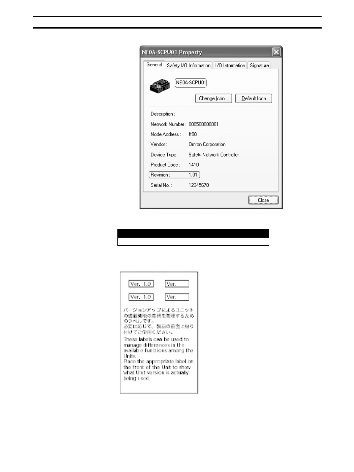
7 Unit Versions of NE0A-series Controllers
Checking the Unit Version
A “unit version” has been introduced to manage NE0A-series Safety Network
Controllers according to differences in functionality accompanying Unit
upgrades even though the model numbers are the same. The unit version can
be checked on the product itself or using the Network Configurator.
Note The Network Configurator maintains a revision number to manage device
functions for DeviceNet and EtherNet/IP. Refer to Checking the Unit Version
with the Network Configurator on page xxiv for the relationship between
NE0A-series Controller unit versions and the revisions.
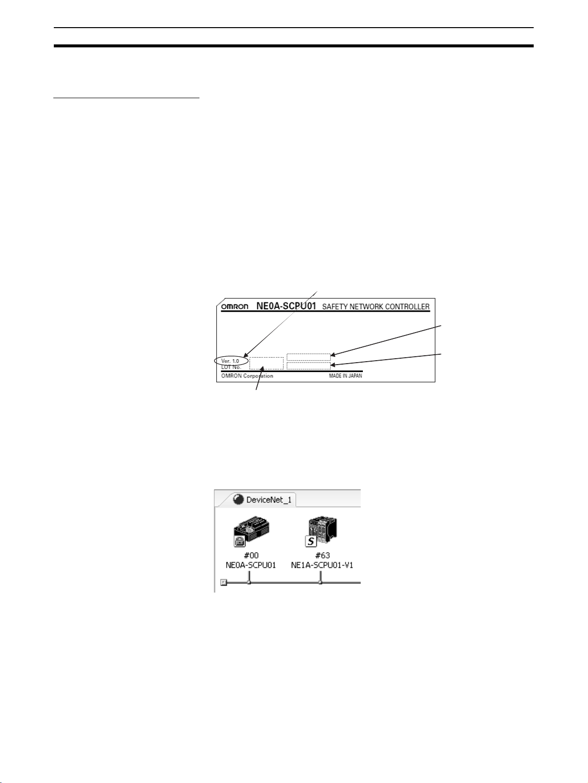
Checking the Unit Version on the Product Nameplate
The unit version (Ver. @.@) is listed near the lot number on the nameplate of
the products for which unit versions are being managed, as shown below.
• Unit versions for the NE0A-SCPU01 start at unit version 1.0.
The unit version is listed here.
Product Nameplate
(Example: Ver. 1.0)
Lot number
Checking the Unit Version with the Network Configurator
The following procedure can be used to check the unit version from the Network Configurator.
1,2,3... 1. Select Network - Upload to upload the configuration information. The de-
vice icons will be displayed, as shown in the following diagram.
2. Right-click on a device icon to display the popup menu shown below and
select Property from the menu.
Serial number
in hexadecimal
Serial number
in decimal
xxiv
Page 24
Unit Versions of NE0A-series Controllers 7
The following Property Dialog Box will be displayed.
The device name and revision are given in the Property Dialog Box. The
NE0A-series Controllers are listed in the following table.
Model Revision Unit version
NE0A-SCPU01 1.01 1.0
Checking the Unit Version with the Unit Version Label
The following unit version labels are provided with the Controller.
These labels can be attached to the front of the Controllers to differentiate
between Controller with different unit versions from the front of the Controller.
xxv
Page 25

Unit Versions of NE0A-series Controllers 7
xxvi
Page 26

SECTION 1
Overview of the NE0A-series Safety Network Controllers
This section provides an overview of the NE0A-series Safety Network Controllers and the type of system configuration in
which they are used.
1-1 About NE0A-series Safety Network Controllers . . . . . . . . . . . . . . . . . . . . . . 2
1-1-1 Introduction to the NE0A-series Safety Network Controllers . . . . . 2
1-1-2 Features of the NE0A-series Controllers . . . . . . . . . . . . . . . . . . . . . 3
1-1-3 Models . . . . . . . . . . . . . . . . . . . . . . . . . . . . . . . . . . . . . . . . . . . . . . . 4
1-2 System Configuration . . . . . . . . . . . . . . . . . . . . . . . . . . . . . . . . . . . . . . . . . . . 5
1-2-1 DeviceNet Safety System Overview. . . . . . . . . . . . . . . . . . . . . . . . . 5
1-2-2 System Configuration Examples . . . . . . . . . . . . . . . . . . . . . . . . . . . 5
1-2-3 Connecting to a Network Configurator . . . . . . . . . . . . . . . . . . . . . . 8
1
Page 27
About NE0A-series Safety Network Controllers Section 1-1
1-1 About NE0A-series Safety Network Controllers
1-1-1 Introduction to the NE0A-series Safety Network Controllers
NE0A-series Safety Network Controllers are programmable safety logic controllers. They are designed for small-scale safety control and provide functions
such as safety logic operations, safety local I/O control functions, and
DeviceNet Safety Slave communications.
An NE0A-series Controller allows the user to construct safety control circuits
that meet the requirements for Safety Integrity Level 3 (SIL 3) according to
IEC 61508 (Functional Safety of Electrical/Electronic/Programmable Electronic Safety-related Systems) and the requirements for Safety Category 4 of
EN 954-1.
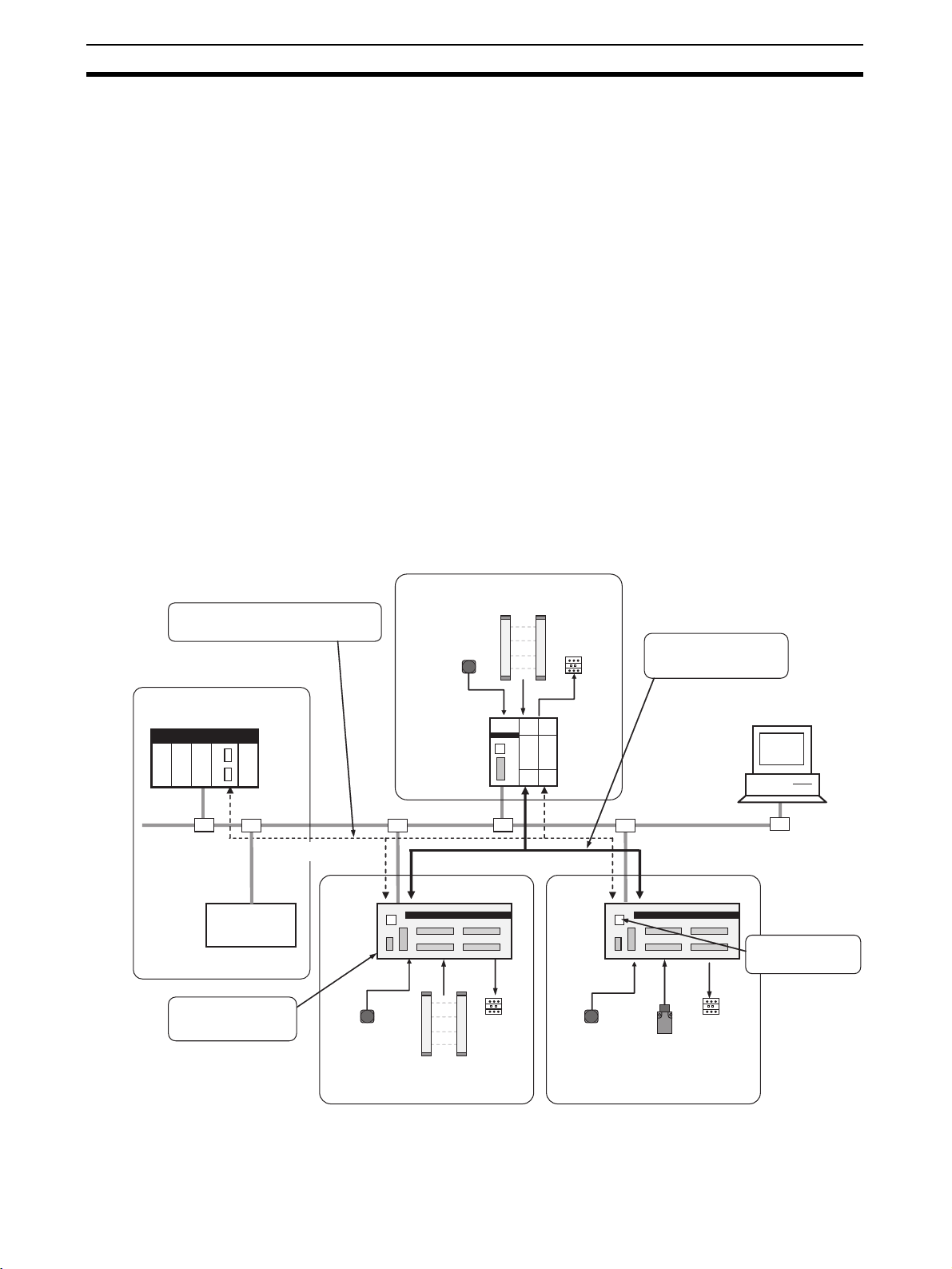
As shown in the following example system configuration, a safety distributed
control system can be constructed with an NE0A-series Controller for each
safety control block. With this system, the following operations are enabled.
• As Safety Logic Controllers, the NE0A-series Controllers execute safety
logic operations and directly control local safety outputs.
• As DeviceNet Safety Slaves, the NE0A-series Controllers perform safety
I/O communications with the NE1A-series DeviceNet Safety Master.
• As a DeviceNet Standard Slave, the NE0A-series Controller communicates with the DeviceNet Standard Master.
Main Safety Control Block
Monitoring safety controls using standard
I/O communications and explicit
message communications
Non-safety Controls (Standard Controls)
Standard PLC
Standard Master
Local safety output
controls using logic
operations
Standard Slave
Standard
communications
NE0A
Emergency
stop switch
Emergency
stop switch
Safety Master
Safety communications
Safety Slave
Safety light curtain
Safety light curtain
Contactor
Contactor
NE0A
Emergency
stop switch
Used in common for
interlock signals, based on
safety I/O communications
Network
Configurator
DeviceNet
Safety Slave
Safety
door switch
Contactor
USB connection for
Network Configurator
Safety Control Sub-block 1
Safety Control Sub-block 2
2
Page 28

About NE0A-series Safety Network Controllers Section 1-1
1-1-2 Features of the NE0A-series Controllers
Constructing Safety Distributed Control Systems for Facilities
Distributing Safety
Control with DeviceNet
Safety
Shorter Safety Response Times
USB Communications
Force-set/reset
Safety control blocks, such as for individual pieces of equipment, can be connected with less wiring by using DeviceNet cables. Using DeviceNet Safety
communications enables transferring interlock signals and other safety data
between blocks, and achieves centralized monitoring with DeviceNet standard
communications.
Safety response times can be shortened because local safety outputs can be
directly controlled without using the Safety Master.
The Network Configurator can be directly connected using USB cable.
Remote I/O signals from a Safety Master can be force-set or force-reset without the Safety Master present, enabling debugging NE0A-series Controllers
individually.
Application Templates
Reducing Design Work with Certified Safety Circuits
Using the preinstalled application templates greatly reduces work for constructing circuits that comply with safety standards.
Safety Logic Operations
Constructing Safety Circuits with Software
Safety circuits can be programmed with a wizard to handle various applications, such as emergency stops, door switches with lock functions, and teaching modes. The safety circuits that are created can be easily debugged by
using a graphical software tool.
Local Safety I/O
Labor-saving Cage Clamp
Termina l Block
Wide Range of I/O Wiring
Error Detection Functions
Safety Inputs • Contact output devices, such as emergency stop switches and semi-con-
• I/O cables can be wired without having to tighten screws.
• The terminal block is removable.
• The terminal block is structured to prevent incorrect insertion.
• For safety inputs, external wiring errors, such as faulty connected devices,
wiring mistakes, disconnected wires, short-circuiting, and ground faults,
can be detected.
• Using safety outputs in combination with the safety logic EDM function
enables detecting errors such as contact weld faults in output devices
such as safety relays and contactors.
• Detected errors are shown using the I/O indicators on the front of the
NE0A-series Controller, making it easy to identify their location. In addition, the cause of an error can be identified using the Network Configurator.
ductor output devices such as light curtains, can be connected.
• ON and OFF input delays can be set.
• In compliance with Category 4, two related inputs can be set as dual
channels.
3
Page 29

About NE0A-series Safety Network Controllers Section 1-1
Safety Outputs • ON and OFF output delays can be set.
• In compliance with Category 4, two related outputs can be set as dual
channels.
DeviceNet Safety and DeviceNet Standard Communications
Simple Settings Only the node address needs to be set using a rotary switch. The baud rate is
recognized automatically, so it does not need to be set.
DeviceNet Safety
Communications
DeviceNet Standard
Communications
• A maximum of two connections for safety I/O communications can be set
for Safety I/O Slaves.
• Safety I/O communications can be used to exchange safety interlock signals such as emergency stop signals with the NE1A-series Safety Master.
• A maximum of two connections for standard I/O communications can be
set for Standard Slaves.
• Standard I/O communications and explicit message communications can
be used to monitor NE0A-series Controller status and error information
from a standard PLC, enabling errors that occur at the Controller to be
immediately identified by standard controls at the PLC.
Access Control with Passwords
Configuration Lock The configuration downloaded to the NE0A-series Controller can be locked. A
password is required to clear the lock, so unauthorized changes can be prevented.
Restrictions on User
Operations
A password must be entered to perform operations such as changing the
operating mode, downloading data, or force-setting/resetting bits, thus preventing unintentional access to the NE0A-series Controllers.
Maintenance Functions
Monitoring I/O Power
Supply Voltage
The local I/O power supply is monitored, and an error occurs if the voltage is
incorrect.
Monitoring Unit Power-ON
Time
Monitoring the Number of
Bit Operations
Monitoring Total ON Time The total time that each input or output bit is ON can be calculated (unit: s)
The total time that power is ON for the internal circuit can be calculated and
saved in the NE0A-series Controller.
The number of times each input or output bit turns ON can be counted and
saved in the NE0A-series Controller.
and saved in the NE0A-series Controller.
1-1-3 Models
The following table lists the model number of the NE0A-series Controller and
the numbers of I/O points.
Model Number of I/O points
Safety inputs Test outputs Safety outputs
NE0A-SCPU01 12 (See note.) 2 6 (semiconductors)
Note IN10 and IN11 are for the reset switch or EDM feedback connection only.
4
Page 30
System Configuration Section 1-2
1-2 System Configuration
1-2-1 DeviceNet Safety System Overview
DeviceNet is an open-field, multi-vendor, multi-bit network, which combines
the controls in the machine and line control levels with information. The
DeviceNet Safety network adds safety functions to the conventional
DeviceNet standard communications protocol. The DeviceNet Safety concept
has been approved by a third-party organization (TÜV Rhineland).
Just as with DeviceNet, DeviceNet Safety-compliant devices from third-party
vendors can be connected to a DeviceNet Safety network. Also, DeviceNetcompliant devices and DeviceNet Safety-compliant devices can be combined
and connected on the same network.
By combining DeviceNet Safety-compliant products, a user can construct a
safety control/network system that meets the requirements for Safety Integrity
Level (SIL) 3 according to IEC 61508 (Functional Safety of Electrical/Electronic/Programmable Electronic Safety-related Systems) and the requirements for Safety Category 4 according to EN 954-1.
Safety Control as a Safety Network
Controller
Safety I/O Communications
-
NE1A-series Safety Network
Controller
-
Safety Master
-
Standard Slave
Safety
communications
Safety Terminal
-
Safety Slave
-
Standard Slave
Network Configurator
Safety
configuration
Standard Control and Monitoring as
a Standard PLC
Standard I/O communications
Explicit message communications
-
Standard PLC/Standard Master
Standard
configuration
Standard
communications
NE0A-series Safety Network
Controller
-
Safety Slave
-
Standard Slave
Standard Slave
1-2-2 System Configuration Examples
The following examples illustrate safety control systems using NE0A-series
Controllers.
• DeviceNet Safety System
• DeviceNet System
• Stand-alone System
5
Page 31

System Configuration Section 1-2
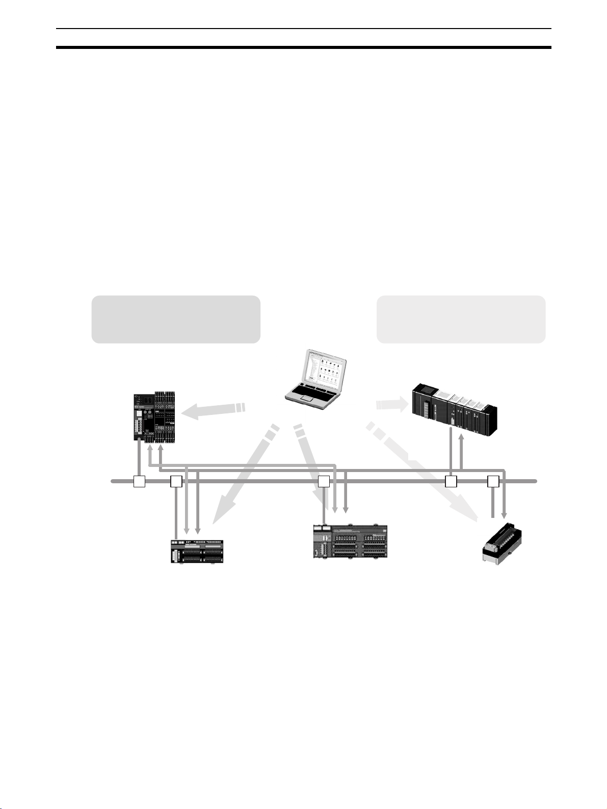
Safety Distributed Control System with DeviceNet Safety
In this example, a safety distributed control system is constructed using a
Safety Master and NE0A-series Controllers. In this system, the Safety Master
controls the entire system while the NE0A-series Safety Slaves control safety
for sub-blocks. The Safety Master executes safety I/O communications with
with NE0A-series Safety Slaves. This enables exchanging safety data, such
as interlock signals, between the NE0A-series Controllers and the Safety
Master.
In addition, using standard I/O communications to assign NE0A-series Controller status information (Unit general status and local I/O errors) and logic
operation results to a standard PLC enables central monitoring of the safety
control system by the standard PLC.
Safety I/O communications
Main Safety Control Block
Safety Master
DST1 Safety Slaves
NE0A
Standard PLC
Standard Master
Monitoring System
Safety Slave
Safety Control Sub-block 1
Standard I/O communications
and explicit messages
NE0A
Safety Slave
Safety Control Sub-block 2
NE0A
Safety Slave
Safety Control Sub-block 3
Note • The NE0A-series Controller uses two Safety Master connection
resources (IN and OUT). For example, up to 16 NE0A-series Controllers
can communicate with one NE1A-SCPU01-V1 Controller, which supports
a total of 32 connections.
• A maximum total of 64 standard nodes and safety nodes can be connected on the same network.
IMPORTANT The data attributes handled by standard I/O communications and explicit
message communications are non-safety data. The necessary measures for
safety data are not taken for this data during data generation. Therefore, do
not use this data to configure the Safety Control System.
Centralized
Monitoring System
with DeviceNet
6
If safety control blocks requiring a small number of I/O points must be distributed, a safety control system can be constructed using only NE0A-series
Controllers without a Safety Master. In this case, the NE0A-series Controllers
operate only as DeviceNet Standard Slaves, and do not handle safety I/O
communications.
Page 32

System Configuration Section 1-2
When small-scale safety control blocks are distributed, monitoring with less
wiring is enabled from a centralized monitoring system through the DeviceNet
network. Error locations and probably causes of errors can be easily identified
by using standard I/O communications and explicit messages to assign
NE0A-series Controller status information and logic operation results to the
standard PLC.
Centralized Monitoring System
Standard PLC
Standard Master
Standard I/O communications
or explicit message
communications
Emergency
stop switch
Emergency
stop switch
Contactors
Light
curtain
NE0A NE0A NE0A
-
Standard Slave
Safety Control Block A
-
Standard Slave
Safety Control Block B
Safety Control Block C
-
Standard Slave
Door
switches
Contactors
IMPORTANT The data attributes handled by standard I/O communications and explicit
message communications are non-safety data. The necessary measures for
safety data are not taken for this data during data generation. Therefore, do
not use this data to configure the Safety Control System.
7
Page 33

System Configuration Section 1-2
Standalone System
If there are only a few I/O points, the NE0A-series Controller can be used as
Standalone Controller.
The Controller’s DeviceNet communications can be disabled through settings
made from the Network Configurator to enable the NE0A-series Controller to
operate as Standalone Controller.
Light curtain
Emergency stop
button
USB communications
Network Configurator
Door switches
NE0A
(Standalone)
Contactors
IMPORTANT Use a USB port connection to set Standalone Mode. DeviceNet communica-
tions are stopped when Standalone Mode is set, and so setting is not possible
from the DeviceNet port.
1-2-3 Connecting to a Network Configurator
Note For details on connecting to a Network Configurator, refer to 7-2 Online Con-
nection in this manual or to the DeviceNet Safety System Configuration Manual (Cat. No. Z905).
8
Page 34

SECTION 2
Nomenclature and Specifications
This section provides the component names and specifications of the NE0A-series Safety Network Controllers. It also
describes the local safety I/O functions that are available.
2-1 Nomenclature . . . . . . . . . . . . . . . . . . . . . . . . . . . . . . . . . . . . . . . . . . . . . . . . . 10
2-1-1 Nomenclature . . . . . . . . . . . . . . . . . . . . . . . . . . . . . . . . . . . . . . . . . . 10
2-1-2 Indicator Area . . . . . . . . . . . . . . . . . . . . . . . . . . . . . . . . . . . . . . . . . . 11
2-1-3 Switch Settings . . . . . . . . . . . . . . . . . . . . . . . . . . . . . . . . . . . . . . . . . 13
2-1-4 DeviceNet Communications Connector . . . . . . . . . . . . . . . . . . . . . . 13
2-1-5 USB Communications Connector. . . . . . . . . . . . . . . . . . . . . . . . . . . 14
2-1-6 Input/Output Terminals and Internal Connections . . . . . . . . . . . . . . 15
2-1-7 Dimensions and Weight . . . . . . . . . . . . . . . . . . . . . . . . . . . . . . . . . . 16
2-2 Specifications . . . . . . . . . . . . . . . . . . . . . . . . . . . . . . . . . . . . . . . . . . . . . . . . . 17
2-2-1 General Specifications . . . . . . . . . . . . . . . . . . . . . . . . . . . . . . . . . . . 17
2-2-2 DeviceNet Communications Specifications . . . . . . . . . . . . . . . . . . . 18
2-2-3 I/O Specifications . . . . . . . . . . . . . . . . . . . . . . . . . . . . . . . . . . . . . . . 19
2-2-4 Wiring I/O Devices . . . . . . . . . . . . . . . . . . . . . . . . . . . . . . . . . . . . . . 20
2-3 Local Safety I/O Functions . . . . . . . . . . . . . . . . . . . . . . . . . . . . . . . . . . . . . . . 23
2-3-1 Local I/O Comments. . . . . . . . . . . . . . . . . . . . . . . . . . . . . . . . . . . . . 23
2-3-2 I/O Power Monitor . . . . . . . . . . . . . . . . . . . . . . . . . . . . . . . . . . . . . . 23
2-3-3 Local Safety Inputs. . . . . . . . . . . . . . . . . . . . . . . . . . . . . . . . . . . . . . 23
2-3-4 Local Safety Output Functions . . . . . . . . . . . . . . . . . . . . . . . . . . . . . 29
9
Page 35

Nomenclature Section 2-1
2-1 Nomenclature
This section describes the part names and functions of the NE0A-series Controllers.
2-1-1 Nomenclature
NE0A-SCPU01
USB port
(B connector)
24-VDC internal
circuit power supply
terminals
Node address switches:
Sets the DeviceNet node address
as a 2-digit decimal number.
Operating status indicators
I/O status indicators
DeviceNet communications connector:
Connects to the network communications cable.
I/O terminal blocks
10
Page 36

Nomenclature Section 2-1
2-1-2 Indicator Area
Operating Status Indicators
Indicator name Color Status Meaning
MS (Module Status) Green RUN Mode
MS
MS
Red Critical fault (fatal error) (See note.)
Green/red Initialization or waiting for configuration
--- Internal circuit power supply not being supplied.
NS (Network Status) Green Online with I/O or explicit message connection established.
MS
MS
MS
MS
NS
NS
IDLE Mode
Abort status (minor error, such as incorrect switch setting or
Force Mode timeout)
Online with I/O or explicit message online connection not
established.
Red Unable to communicate. (Bus Off error or duplicated node
NS
addresses detected.)
NS
I/O communications error
--- • Internal circuit power supply not being supplied. (MS indicator
NS
also not be lit.)
• Communications power supply not being supplied.
• Offline.
• Stand-alone operation (DeviceNet communications disabled).
FORCE (Force-set/
reset Status)
Yellow Force-setting/resetting enabled. (Force Mode) (Force-setting/
resetting is being used.)
--- Force-setting/resetting disabled. (Force-setting/resetting is not
being used.)
LOCK (Configuration
Yellow Configuration is valid and locked.
Lock)
Configuration is valid and not locked.
COMM
(USB)
No valid configuration.
Yellow Data communications in progress.
Data communications not in progress.
: ON, : Flashing, : OFF
Note A system error has been caused by a malfunction or incorrectly wired safety
output terminals.
11
Page 37

Nomenclature Section 2-1
I/O Status Indicators
Indicator name Color Status Meaning
IN PWR
(Input Power)
Green Input power supply normal.
Input power supply not being supplied.
OUT PWR
(Output Power)
IN 0 to n
(See note.)
(IN Status)
OUT 0 to n
(See note.)
(OUT Status)
Green Output power supply normal.
Output power supply not being supplied.
Yellow Input signal ON.
Red • Error detected in input circuits.
• Discrepancy (input data mismatch) in Dual Channel Mode
settings.
Error detected in other input in Dual Channel Mode (with no
error for this input).
- • Input signal OFF.
• Initialization in progress.
• Waiting for configuration.
• Fatal error
Yellow Output signal ON.
Red • Error detected in output circuits.
• Dual channel violation (output data mismatch) in Dual Chan-
nel Mode.
• EDM error occurred (when EDM (weld check) is enabled).
Error detected in other output in Dual Channel Mode (with no
error for this output).
- • Input signal OFF.
• Initialization in progress.
• Waiting for configuration.
• Fatal error
: ON, : Flashing, : OFF
Note “n” indicates the terminal number.
!WARNING
Serious injury may possibly occur due to loss of required safety functions.
Do not use the NE0A-series Controller's indicators for safety operations.
Note The errors are indicated by indicator combinations. For the meanings of spe-
cific indications, refer to SECTION 12 Troubleshooting.
12
Page 38

Nomenclature Section 2-1
2-1-3 Switch Settings
Node Address Switches
Set the DeviceNet node address using the rotary switches on the front of the
NE0A-series Controller.
Method Two-digit decimal number
Range 0 to 63 (default: 63)
IMPORTANT
• Turn OFF the communications power supply before setting the node
address.
• Do not change the rotary switches while the power is ON. The Controller
will detect this as a change in the configuration and will switch to ABORT
State.
• Use a small, flat-blade screw driver to set the node address. Be careful
not to damage the switches.
2-1-4 DeviceNet Communications Connector
Labels are placed on the DeviceNet communication connectors for the colors
of the communications wires. By matching the communications wire colors
with the label colors, you can check to see if wires are in the correct locations.
The colors of the wires are as follows:
V+
CAN H
Shield
CAN L
V−
For details on communications specifications, wiring, and communications
power supply methods, refer to the DeviceNet Operation Manual (Cat. No.
W267).
IMPORTANT
• When connecting the communications connector to the NE0A-series
Controller, tighten the connector screws to a torque of 0.25 to 0.3 N·m.
• Turn OFF the power supply to the NE0A-series Controller, communications power supply, and all nodes on the network before starting any wiring operations.
• Keep the communications cables separate from high-voltage cables and
power lines.
Color Description
Red Power supply cable
positive (V+)
White Communications data
high signal (CAN H)
-Shield
Blue Communications data
low signal (CAN L)
Black Power supply cable
negative (V−)
13
Page 39

Nomenclature Section 2-1
2-1-5 USB Communications Connector
A personal computer must be connected to the NE0A-series Controller to use
the Network Configurator. Use a commercially available USB cable for the
connection. The connector on the cable to the NE0A-series Controller is a Btype male USB connector.
IMPORTANT The USB cable must be no longer than 3 m.
14
Page 40

Nomenclature Section 2-1
2-1-6 Input/Output Terminals and Internal Connections
NE0A-SCPU01
V0
24 VDC
G0
DC-DC converter
not isolated
V+
CAN H
Shield
CAN L
V−
D+
D−
DeviceNet
physical layer
DC-DC converter
not isolated
USB
Internal circuits
Safety input and test
output circuits
Safety output circuits
V1
G1
T0
T1
IN0
IN8
T0
T1
IN9
IN10
IN11
V2
G2
OUT0
OUT5
24 VDC
24 VDC
L
L
Terminal No. Terminal name Description
--- V0
Power supply terminals for internal circuits (24 VDC)
--- G0
1 V1 Power supply terminals for external input devices and test outputs (24 VDC)
11 G1
24 V2 Power supply terminals for external output devices (24 VDC)
34 G2
2-10 IN0 to IN8 Safety input terminals IN10 and IN11 are used for a reset switch or for con21-23 IN9 to IN11
12-20
T0 to T1 Test output terminals connected to safety inputs IN0 to IN11. T0 and T1 out-
31-33
necting EDM feedback.
put different test pulse patterns. The T0 terminals are internally connected
and the T1 terminals are internally connected.
25-30 OUT0 to OUT5 Safety output terminals
35-40 G2 Common terminals
Terminals 34 to 40 are internally connected.
15
Page 41

Nomenclature Section 2-1
2-1-7 Dimensions and Weight
Dimensions
NE0A-SCPU01
80 mm
(90 mm)
Weight
71.4 mm
NE0A-SCPU01 440 g max.
Model Weight
190 mm
16
Page 42

Specifications Section 2-2
2-2 Specifications
2-2-1 General Specifications
NE0A-SCPU01
Item Specifications
DeviceNet supply voltage 11 to 25 VDC
(Supplied from communications connector.)
Device supply voltage V0 (See note.) 20.4 to 26.4 VDC (24 VDC, −15% to 10%)
I/O supply voltages V1 and V2
(See note.)
Current con-
sumption
Overvoltage category II
EMC Conforms to IEC 61131-2.
Vibration resistance
Shock resistance
Mounting DIN Track (TH35-7.5/TH35-15 according to IEC 60715)
Operating temperature −10 to 55°C
Humidity 10% to 95% (with no condensation)
Storage temperature −40 to 70°C
Degree of protection IP20
Serial interface USB Ver. 1.1
Weight 440 g max.
DeviceNet 15 mA at 24 VDC
Internal logic circuits 110 mA at 24 VDC
20.4 to 26.4 VDC (24 VDC, −15% to 10%)
2
0.35 mm at 10 to 57 Hz, 50 m/s
2
150 m/s
for 11 ms
at 57 to 150 Hz
Note V0 to G0: For internal logic circuits, V1 to G1: For external input devices and
test outputs, V2 to G2: For external output devices.
17
Page 43

Specifications Section 2-2
2-2-2 DeviceNet Communications Specifications
Item Specifications
Communications
protocol
Connection method The multidrop and T-branch connections can be combined (for main line and branch lines).
Baud rate 500 kbits/s, 250 kbits/s, 125 kbits/s
Communications
medium
Communications
distance
Communications power
supply
Connected nodes 63 nodes max.
Safety I/O
communications
Standard I/O
communications
Message communications
Conforms to DeviceNet.
Special cable with 5 lines (2 communications lines, 2 power lines, 1 shield line)
Baud rate Maximum network length Branch length Total length
500 kbits/s 100 m max. (100 m max.) 6 m max. 39 m max.
250 kbits/s 250 m max. (100 m max.) 6 m max. 78 m max.
125 kbits/s 500 m max. (100 m max.) 6 m max. 156 m max.
The numbers in parentheses are the lengths when Thin Cable is used.
11 to 25 VDC
Safety Slave Function:
• 2 (one each for IN and OUT)
With multi-cast inputs, however, communications is possible for a maximum of 15 Safety
Masters.
• Connection type: Single-Cast, Multi-Cast
Standard Slave Function
• Maximum number of connections: 2
• Connection type: Poll, Bit-strobe, COS, Cyclic
Maximum message length: 502 bytes
18
Page 44

Specifications Section 2-2
2-2-3 I/O Specifications
Safety Inputs
Item Specifications
Input type Current sinking (PNP)
ON voltage 11 VDC min. between each input terminal and G1
OFF voltage 5 VDC max. between each input terminal and G1
OFF current 1 mA max.
Input current 4.5 mA
Test Outputs
Item Specifications
Output type Current sourcing (PNP)
Rated output current 60 mA max.
Residual voltage 1.2 V max. between each output terminal and V1
Leakage current 0.1 mA max.
IMPORTANT Test outputs can be used only for outputs with test pulses. They are con-
nected to safety inputs through contact output devices.
Safety Outputs
Item Specifications
Output type Current sourcing (PNP)
Rated output current 0.5 A per output
Residual voltage 1.2 V max. between each output terminal and V2
Leakage current 0.1 mA max.
IMPORTANT If the channel mode of a safety output terminal is set as Safety Pulse Test, an
OFF pulse signal (pulse width: 580 µs) will be output to diagnose the output
circuit when the safety output turns ON. Check the input response time of the
output device to be sure that this OFF pulse will not cause malfunctions.
Refer to 2-3 Local Safety I/O Functions for information on the channel mode.
Approx. 378 ms
ON
OFF
Approx. 580 µs
19
Page 45

Specifications Section 2-2
2-2-4 Wiring I/O Devices
Wiring Input Devices
Refer to the following information for input device selection and wiring.
■ Devices with Mechanical Contact Outputs
Examples: Emergency stop buttons and safety limit switches
These devices use both a safety input terminal and test output terminal. A
safety input terminal inputs the test output signal (pulse output) of the NE0Aseries Controller via a contact output device.
4.5 mA typical
V1
Tx
NE0A-series
Controller
INx
Minimum applicable load:
4 mA, 24 VAC
24 VDC
G1
■ Devices with PNP Semiconductor Outputs (Current Sourcing)
Example: Light curtains
A PNP semiconductor output signal from this type of device is input to the
NE0A-series Controller’s safety input terminal.
4.5 mA typical
V1
24 VDC
OSSDx
GND
Tx
INx
24 VDC
G1
NE0A-series
Controller
!WARNING
Serious injury may possibly occur due to loss of required safety functions. Use appropriate components or devices according to the requirements given in the following table.
20
Page 46

Specifications Section 2-2
Controlling devices Requirements
Emergency stop switch Use approved devices with a direct opening mechanism compliant with IEC/
Door interlocking switch or
limit switch
Safety sensor Use approved devices compliant with the relevant product standards, regula-
Relay with forcibly guided contacts Use approved devices with forcibly guided contacts compliant with EN 50205.
Contactor Use contactors with a forcibly guided mechanism and monitor the auxiliary NC
Other devices Evaluate whether devices used are appropriate to satisfy the requirements of
IMPORTANT
EN 60947-5-1.
Use approved devices with a direct opening mechanism compliant with IEC/
EN 60947-5-1 and capable of switching micro-loads of 4 mA at 24 VDC.
tions, and rules in the country where they are used.
For feedback, use devices with contacts capable of switching
micro-loads of 4 mA at 24 VDC.
contact to detect contactor failures.
For feedback, use devices with contacts capable of switching micro-loads of
4 mA at 24 VDC.
the safety category level.
• Properly apply the specified voltage to the NE0A-series Controller’s
inputs. Applying an inappropriate DC voltage or any AC voltage may
cause reduced safety functions, damage to the NE0A-series Controller, or
a fire.
• Be sure to separate I/O cables from high-voltage/current lines.
• Use I/O cables of 30 m or less.
• Do not apply the power supply to the test output terminals. Doing so may
result in product damage or burning.
Wiring Output Devices
Refer to the following diagram for selection and wiring of output devices.
0.5 A max.
V2
24 VDC
NE0A-series
OUTx
Controller
L
G2
21
Page 47

Specifications Section 2-2
!WARNING
Serious injury may possibly occur due to breakdown of outputs. Do not connect loads
beyond the rated value to the safety outputs and the test outputs.
Serious injury may possibly occur due to loss of required safety functions. Wire the
NE0A-series Controller properly so that 24-VDC lines do NOT touch the safety outputs
and the test outputs accidentally or unintentionally.
Serious injury may possibly occur due to loss of required safety functions. Ground the 0V line of the power supply for external output devices so that the devices do NOT turn
ON when the safety output line or the test output line is grounded.
Serious injury may possibly occur due to loss of required safety functions. Use appropriate components or devices according to the requirements given in the following table.
Controlling Devices Requirements
Contactor Use contactors with a forcibly guided mechanism and monitor the auxiliary NC
contact to detect contactor failures.
For feedback, use devices with contacts capable of switching micro-loads of
4 mA at 24 VDC.
Other devices Evaluate whether devices used are appropriate to satisfy the requirements of
safety category level.
IMPORTANT
• Be sure to separate I/O cables from high-voltage/current lines.
• Use output cables of 30 m or less (the output cable length).
• Do not apply the power supply to the test output terminals. Doing so may
result in product damage or burning.
In addition, if an attempt is made to start the Unit while power is being
applied to the output terminals, a fatal error will occur, the MS indicator
will light red, and the Unit will not start normally.
22
Page 48

Local Safety I/O Functions Section 2-3
2-3 Local Safety I/O Functions
2-3-1 Local I/O Comments
An optional name of up to 32 characters can be registered in the NE0A-series
Controller for each I/O terminal, using the Network Configurator. I/O comments are registered in the safety logic settings of the NE0A-series Controller
and in the NE1A-series Logic Editor as I/O tag names, enabling easy conceptualization of what is actually being controlled and simplifying programming.
Note For details on making settings using the Network Configurator, refer to 6-3-3
Setting Local I/O Terminals (Safety Wizard).
2-3-2 I/O Power Monitor
The I/O power supply input can be monitored to confirm if it is normal. If an
I/O terminal on the NE0A-series Controller is set to any setting other than Not
Used and the normal power supply voltage is not input, an error will be
detected and can be confirmed using the following:
• The IN PWR and OUT PWR indicators on the front of the Unit will turn
OFF.
• The error will be registered in the error history and can be monitored
using the Network Configurator.
• The error will be shown in the Unit general status and can be monitored
using an NE1A-series Standard PLC.
Note (1) For details on the indicators, refer to 2-1-2 Indicator Area.
(2) For details on the error history, refer to SECTION 12 Troubleshooting.
(3) For details on Unit general status, refer to 6-5 Remote I/O Allocations.
2-3-3 Local Safety Inputs
Overview
Connecting to Contact
Output Safety Devices
A test pulse signal for the NE0A-series Controller is input by connecting to a
contact output device. Input signal line errors, such as the following, can be
detected by inputting the test pulse signal.
T0 T1
11 21
12 22
IN1IN0
The following can be detected by using the
test pulse signal.
• Contact with the power supply line (positive side)
• Ground faults
• Short-circuits between input signal lines
Connecting
Semiconductor Output
Safety Devices
The output from a 24-VDC semiconductor, such as the OSSD output from a
Light Curtain, is input. Errors in the OSSD output signal line (i.e., the NE0Aseries Controller’s input signal line) is detected at the external connection
device.
23
Page 49

Local Safety I/O Functions Section 2-3
Light
Curtain
OSSD1
Sourcing
OSSD2
Sourcing output (PNP)
output
(PNP)
IN1IN0
Input Channel Mode
Set the input channel mode for the safety inputs according to the type of the
external device to be connected.
Channel mode Symbol Description
Not Used --- Specifies to not use an external input device.
Test pulse from test
out
[P] Specifies connecting a safety device with a con-
tact output in combination with a test output.
Used as safety input [s] Specifies connecting a safety device with a semi-
conductor output, such as a light curtain.
Used as standard
input
[ST] Specifies connecting a standard device (i.e., non-
safety device).
Note These symbols are used for notation in the displays for confirming I/O settings
in the Safety Wizard.
Test Pulses
Detecting Input Signal Line Errors with Test Pulses (Input Circuit Diagnosis)
A test pulse is output from the test output terminal to diagnose the internal circuit when the external input contact turns ON. Using this function, short-circuits between input signal lines and the power supply (positive side), and
short-circuits between input signal lines can be detected.
24
24 V
V
G
T0
IN0
T1
IN1
24 V
0 V
External contact
Short-circuit between input
signal line and power supply
(positive side)
External contact
Short-circuit between input signal lines
Page 50

Local Safety I/O Functions Section 2-3
If an error is detected, safety input data and individual safety input status will
turn OFF.
* Normal
24 V
T0
0 V
Remote
I/O data
* Error
Remote
I/O data
External device
IN0
Safety input 0
Status of
safety
input 0
T0
External device
IN0
Safety input 0
Status of
safety
input 0
ON
OFF
ON
OFF
ON
OFF
ON
OFF
24 V
0 V
ON
OFF
ON
OFF
ON
OFF
ON
OFF
Error
Test Source When the input channel mode is set to Test pulse from test out, select the test
output to use for the test source. Specify different test outputs if it is necessary
to detect short-circuits between input wiring.
If detecting short-circuits
between input wiring is required.
If detecting short-circuits
between input wiring is not required.
25
Page 51

Local Safety I/O Functions Section 2-3
y
y
Note (1) For the NE0A-SCPU01, you can select T0 or T1 as the test source.
(2) Change the test source by using the settings in the Safety Wizard, as de-
scribed below.
1,2,3... 1. Click the Advanced Edit Button in the Edit Input Bits Window or the Edit
Output Bits Window.
2. Open the safety input settings for the safety input, and change the test
source.
Input Delays
ON delays and OFF delays can be set for the safety inputs of the NE0A-series
Controller between 0 and 994 ms (in increments of 7 ms). The effect of chattering from external devices can be reduced by increasing these values.
Limit switch or
other input
I/O tag
T ON delay
IMPORTANT Add both the input ON delay and input OFF delay to the I/O response perfor-
mance. For further details, refer to 3-2 Reaction Time.
Single Channel and Dual Channel Modes
The NE0A-series Controller can use safety inputs with a single channel mode
or dual channel mode. For dual channel mode, you can further select equivalent logic or complementary logic.
T OFF dela
26
Single Channel
Dual Channel
Equivalent
Dual Channel
Complementar
Page 52

Local Safety I/O Functions Section 2-3
The following actions can be performed if Dual Channel Mode is set:
• Evaluating the data of two inputs and inputting the results to safety logic
operations.
• Evaluating the discrepancy time between the data of two inputs.
Channel mode Symbol Description
Single Channel --- Used as an independent safety input.
Dual Channel Equiv-
alent
Dual Channel Com-
plementary
Note These symbols are used for notation in the display for confirming I/O settings
in the Safety Wizard.
Dual Channel Evaluation The data input to the safety input terminals is checked for logic discrepancies
using dual channels when dual channel mode is set.
Channel mode Input signals of
SIngle Channel 0 --- 0 --- Inactive (OFF)
Dual Channel
Equivalent
Dual Channel
Complementary
[e] Used as a Dual Channel Equivalent Input with the
[c] Used as a Dual Channel Complementary Input
safety input
terminals
IN (n) IN (n+1) IN (n) IN (n+1)
1 --- 1 --- Active (ON)
0000Inactive (OFF)
0100Discrepant
1000Discrepant
1111Active (ON)
0001Discrepant
0101Inactive (OFF)
1010Active (ON)
1101Discrepant
paired safety input.
with the paired safety input.
Value after
evaluation
Meaning of status
n = Even number
Discrepancy Time Evaluation (Monitoring Logic Discrepancies between Two Inputs)
For two inputs set in Dual Channel Mode, the time is monitored from a change
in the value of one input to a change in the value of the other input (called the
discrepancy time). When the value of the other input does not change within
the set discrepancy time, it is treated as an error. The discrepancy time can
be set in increments of 10 ms between 0 (disabled) and 65,530 ms. In the
Safety Wizard, it is set to 500 ms. The discrepancy time cannot be set in Single Channel Mode.
27
Page 53

Local Safety I/O Functions Section 2-3
Operation for Dual Channel Equivalent Inputs: Normal Operation
IN0 terminal
IN1 terminal
Discrepancy time
I/O tag IN0
I/O tag IN1
Normal
IN0, IN1
status
Discrepancy time
Operation for Dual Channel Equivalent Inputs: Discrepancy Error
IN0
IN1
Discrepancy time
IN0
IN1
Discrepancy time
Error Handling
Behavior at Error
Detection in Single
Channel Mode
I/O tag IN0
I/O tag IN1
IN0, IN1
status
Normal
Error
I/O tag IN0
I/O tag IN1
IN0, IN1
status
Normal
Error
The following operations are performed if an error is detected during self-diagnosis.
• Input evaluation results corresponding to safety inputs for which errors
have been detected are made inactive.
• The indicator of the safety input with the error lights red.
• The error appears in the error history.
• The NE0A-series Controller continues to operate.
28
Page 54

Local Safety I/O Functions Section 2-3
Behavior at Error
Detection in Dual Channel
Mode
Error Latch Time Setting
The following operations are performed if an error is detected during self-diagnosis.
• Input evaluation results corresponding to safety input pairs for which
errors have been detected are made inactive.
• The indicators of both the safety input terminals with the error light red.
• The error appears in the error history.
• The NE0A-series Controller continues to operate.
The following operations are performed if an error is detected in one of the
two inputs.
• Input evaluation results corresponding to safety input pairs for which
errors have been detected are made inactive.
• The indicator of the safety input with the error lights red, and the indicator
of the other input flashes red
• The error appears in the error history.
• The NE0A-series Controller continues to operate.
The time to latch the error state when an error occurs in a safety input or test
output can be set. The error state will continue until the error latch time
passes even if the cause of the error is momentarily removed. When monitoring errors from a monitoring system, take the monitoring interval into account
when setting the error latch time. The error latch time can be set in increments
of 10 ms between 0 and 65,530 ms. The default is 1,000 ms.
Resetting Errors
All the following conditions must be met to reset errors that occur in the safety
inputs.
• The cause of the error is removed.
• The latch error time has elapsed.
• An inactive signal is input (e.g., pressing the emergency stop button or
opening a door).
2-3-4 Local Safety Output Functions
Overview
The safety outputs of the NE0A-series Controller can be flexibly set to handle
various applications by selecting the setup and wiring to match the type of
external device to be connected and the safety level to be achieved.
The safety outputs of the NE0A-series Controller can detect output signal line
errors, such as the following.
• Contact with the power supply line (positive side, only when the output is
OFF)
• Ground faults
If the test pulse is enabled, the following errors can be detected.
• Contact with the power supply line (positive side, when the output is ON
or OFF)
• Ground faults
• Short-circuits between output lines
29
Page 55

Local Safety I/O Functions Section 2-3
Output Channel Mode
Set the output channel mode for the safety outputs according to the external
device that is connected.
Channel mode Symbol Description
Not Used --- An output device is not connected.
Safety [s] A test pulse is not output when the output is ON. Con-
tact with the power supply line (positive side) when the
output is OFF and ground faults will not be detected.
Safety Pulse
Te st
[P] A test pulse is output when the output is ON. Contact
with the power supply line (positive side) with output ON
or OFF, ground faults, and short-circuits between output
signals can be detected.
Note These symbols are used for notation in the displays for confirming
I/O settings in the Safety Wizard.
IMPORTANT If the channel mode is set to the Safety Pulse Test Mode, an OFF pulse signal
(pulse width: 580 ms) will be output to diagnose the output circuit when the
safety output turns ON. Check the input response time of the control device
connected to the NE0A-series Controller to be sure that this OFF pulse will
not cause malfunctions.
Single Channel and Dual Channel
The safety outputs of the NE0A-series Controller can be used in Single Channel or Dual Channel Mode. (Only equivalent logic can be used in Dual Channel mode.)
The following operations are performed when Dual Channel Mode is set.
• An error occurs if the two outputs from the safety logic operation are not
equivalent.
• If an error is detected in at least one of the two output terminals, the two
outputs for the external device are both turned OFF.
Channel Mode Description
Single Channel Used as an independent safety input terminal.
Dual Channel Used as Dual Channel output with a paired safety input. The
output can turn ON if the paired safety input is normal.
Note There is no discrepancy time setting for safety outputs.
Dual Channel Evaluation The data input to the safety input terminals is checked for logic discrepancies
when Dual Channel Mode is set.
Channel mode Values after logic
operation
OUT (n) OUT
(n+1)
Single Channel 0 --- 0 --- Inactive (load OFF)
1 --- 1 --- Active
Dual Channel 0 0 0 (OFF) 0 (OFF) Inactive (load OFF)
0 1 0 (OFF) 0 (OFF) Output data error (load
1 0 0 (OFF) 0 (OFF) Output data error (load
1 1 1 (ON) 1 (ON) Active
Output signals
from safety
output terminals
OUT (n) OUT
(n+1)
Meaning of status
OFF)
OFF)
n = Even number
30
Page 56

Local Safety I/O Functions Section 2-3
Error Handling
Behavior at Error
Detection in Single
Channel Mode
Behavior at Error
Detection in Dual Channel
Mode
The following operations are performed if an error is detected during self-diagnosis.
• The safety inputs for which errors have been detected are made inactive
regardless of the results of the safety logic operations.
• The indicator of the safety input with the error lights red.
The error appears in the error history.
•
• The NE0A-series Controller continues to operate.
The following operations are performed if an error is detected in one of the
two inputs.
• Outputs to external devices are immediately made inactive regardless of
the results of the safety logic operations.
• The indicator of the safety input with the error lights red, and the indicator
of the other input flashes red.
•
The error appears in the error history.
• The NE0A-series Controller continues to operate.
The following operations are performed
minals are not equivalent
• Outputs to external devices are made inactive regardless of the results of
the safety logic operations
• The indicators of both the safety input terminals with the error light red.
•
The error appears in the error history
• The NE0A-series Controller continues to operate
.
if the two outputs from the output ter-
Error Time Latch Setting Error latching is provided, just as with safety input circuits. The error latch time
can be set in increments of 10 ms between 0 and 65,530 ms. The default is
1,000 ms.
Resetting Errors All the following conditions must be met to reset errors that occur in the safety
input terminals.
The cause of the error must be removed.
•
• The latch error time must have elapsed.
• The output signal to the output terminal must be inactive after safety logic
operations for the corresponding safety output terminal.
31
Page 57

Local Safety I/O Functions Section 2-3
32
Page 58

SECTION 3
Response Performance
This section provides information require to access the response performance of the NE0A-series Safety Network
Controllers.
3-1 Start Time . . . . . . . . . . . . . . . . . . . . . . . . . . . . . . . . . . . . . . . . . . . . . . . . . . . . 34
3-2 Reaction Time . . . . . . . . . . . . . . . . . . . . . . . . . . . . . . . . . . . . . . . . . . . . . . . . . 36
3-2-1 Reaction Time Concepts. . . . . . . . . . . . . . . . . . . . . . . . . . . . . . . . . . 36
3-2-2 Local Input and Local Output Reaction Times. . . . . . . . . . . . . . . . . 36
3-2-3 Input Reaction Time . . . . . . . . . . . . . . . . . . . . . . . . . . . . . . . . . . . . . 36
3-2-4 Output Reaction Time. . . . . . . . . . . . . . . . . . . . . . . . . . . . . . . . . . . . 36
33
Page 59

Start Time Section 3-1
t
3-1 Start Time
Operation Flow The following flowchart shows the operation cycle of the NE0A-series Control-
ler.
Power ON
Initialization
System processing
I/O refresh
Cycle time
(cannot be changed)
DeviceNet/USB
communications processing
User application processing
(logic operations)
Initialization Time The NE0A-series Controller performs initialization when the power supply is
turned ON. During initialization, the NE0A-series Controller performs hardware self-diagnosis. The initialization takes up to 5 s to be completed from the
time that the power is turned ON.
DeviceNet Network
Online Connection
Time
Once the NE0A-series Controller has completed initialization, it will connect to
the DeviceNet network after the following operations have been executed:
• Automatic baud rate detection
• Node address duplication check
When the online connection has been established, the NS indicator will light
or flash green.
The time required to connect to the network depends on the system configuration.
The NE0A-series Controller matches the baud rate to the network baud rate,
so it cannot detect the baud rate and connect to the network if there are no
frames being sent over the network. The time required for the NE0A-series
Controller to connect to the network will therefore depend on the system configuration, as shown in the following examples, so calculate the time according
to the system being used.
Example 1: Communications Frames Continuously Being Sent Over the Network
Power ON
NE0A
Initialization
5 s max.
Communications frames
Baud rate detected
1 s max.
Node address
duplication
check
2 s max.
Connection to DeviceNe
34
Page 60

Start Time Section 3-1
Example 2: Starting Simultaneously with the NE1A-SCPU01-V1 (Fixed Baud Rate)
Power ON
NE0A
NE1A-
SCPU01-V1
Ve2.0
Initialization
5 s max.
Initialization
14 s max.
Baud rate detected
Node address
duplication
check
2 s max.
Node address
duplication
check
2 s max.
Communications frames
Connection to DeviceNet
Connection to DeviceNet
Time Until Start of NE0A-series Controller Operation (RUN Mode)
When the NE0A-series is set for automatic operation (i.e., Automatic Execution Mode), operation (RUN) will start within 5 s after the power is turned ON.
To confirm from an NE1A-series Controller or standard PLC whether NE0Aseries Controller operation has started normally, monitor the RUN Status Flag
and the Normal Status Flag in the General Status, in the Remote Input Byte
Area, or by using an additional output.
Note (1) For details on General Status and the Remote Input Byte Area, refer to 6-
5 Remote I/O Allocations.
(2) For details on additional outputs, refer to 6-4-6 Safety Output Evaluation.
35
Page 61

Reaction Time Section 3-2
3-2 Reaction Time
3-2-1 Reaction Time Concepts
The reaction time is the time required to stop machine operation in a worstcase scenario considering the occurrence of faults and failures in the safety
chain.
The reaction time is used to calculate the safety distance.
3-2-2 Local Input and Local Output Reaction Times
NE0A-series Controller local input, logic operation, and local output reaction
times can be determined as given below.
Safety Sensor/
Switch
Sensor/Switch
reaction time
Local input or output reaction time = 20 ms + Input ON/OFF delay time + Output ON/OFF delay time
3-2-3 Input Reaction Time
The input reaction time is the time from when an input terminal signal is
changed until the signal is sent to the network. The input reaction time is
determined as given below.
Safety Sensor/
Switch
Sensor/Switch
reaction time
Input reaction time = 25 ms + Input ON/OFF delay time
3-2-4 Output Reaction Time
The output reaction time is the time from when a network signal is received
until the output terminal is changed.
NE0A-series
Controller
Local input or
output
reaction time
NE0A-series
Controller
Input
reaction time
Actuator
Actuator
reaction time
Network
reaction time
Safety Master
Remote input
or local output
reaction time
Actuator
Actuator
reaction time
36
Safety Sensor/
Switch
Sensor/Switch
reaction time
Safety Master
Local input or
output
reaction time
Network
reaction time
NE0A-series
Controller
Output
reaction time
Actuator
Actuator
reaction time
Output reaction time = 10 ms + Output ON/OFF delay time
Note For details on overall system reaction times, refer to the DeviceNet Safety
System Configuration Manual (Cat. No. Z905).
Page 62

SECTION 4
General Procedure
This section describes the overall procedure required to use an NE0A-series Safety Network Controller.
4-1 Overview of Procedure . . . . . . . . . . . . . . . . . . . . . . . . . . . . . . . . . . . . . . . . . . 38
37
Page 63

Overview of Procedure Section 4-1
4-1 Overview of Procedure
The following diagram shows the general procedure for using NE0A-series
Controllers. For details on the network configuration and connection types,
refer to the DeviceNet Operation Manual (Cat. No. W267).
Determine system configuration.
Using DeviceNet Communications
Standalone Operation
5-1 Installation
5-2 Wiring
2-1 Nomenclature
Mount to control panel.
Wire inputs and outputs.
Set node address switch and connect
DeviceNet communications connector.
Create the configuration.
(1) Create virtual network.
• Create virtual network.
• Set network address.
• Wire devices, change node addresses, and change names.
(2) Create NE0A configuration.
• Select configuration plate.
• Set local I/O terminals. (Safety I/O Wizard)
• Set remote I/O data. (Not required for stand-alone operation.)
• Set safety logic. (Safety Logic Wizard)
(3) Allocate remote I/O. (Not required for stand-alone operation.)
• Allocate I/O for Safety Master.
Using Network
Configurator
• Allocate I/O for Standard Master.
• Connect Network Configurator online.
• Download the configuration.
Mount to control panel.
Wire inputs and outputs.
SECTION 6 Creating Configurations
5-1 Installation
5-2 Wiring
Operation and Debugging
Set configuration. (Lock configuration.)
Operate system.
8-2 Changing the Operating Mode
SECTION 9 Monitoring
8-3 Configuration Lock and Automatic Operation
38
Page 64

Installation and Wiring
This section describes how to install and wire an NE0A-series Safety Network Controller.
5-1 Installation. . . . . . . . . . . . . . . . . . . . . . . . . . . . . . . . . . . . . . . . . . . . . . . . . . . . 40
5-1-1 Requirements for Installation and Wiring . . . . . . . . . . . . . . . . . . . . 40
5-1-2 Mounting to the Control Panel . . . . . . . . . . . . . . . . . . . . . . . . . . . . . 41
5-2 Wiring . . . . . . . . . . . . . . . . . . . . . . . . . . . . . . . . . . . . . . . . . . . . . . . . . . . . . . . 43
5-2-1 General Instructions on Wiring. . . . . . . . . . . . . . . . . . . . . . . . . . . . . 43
5-2-2 Wiring the Power Supply and I/O Lines. . . . . . . . . . . . . . . . . . . . . . 44
SECTION 5
39
Page 65

Installation Section 5-1
5-1 Installation
5-1-1 Requirements for Installation and Wiring
Consider the following for installation and wiring to improve the reliability of
the NE0A-series Safety Network Controller System and to fully exploit the
system’s capabilities.
Installation and Storage Environment
Do not use or store the NE0A-series Controller in any of the following locations.
• Locations subject to direct sunlight
• Locations subject to temperatures or humidity outside the ranges specified in the specifications
• Locations subject to condensation as the result of severe changes in temperature
• Locations subject to corrosive or flammable gases
• Locations subject to dust (especially iron dust) or salts
• Locations subject to water, oil, or chemicals
• Locations subject to shock or vibration
Take appropriate and sufficient measures when installing systems in the following locations. Inappropriate and insufficient measures may result in malfunction.
• Locations subject to static electricity or other forms of noise
• Locations subject to strong electromagnetic fields
• Locations subject to possible exposure to radioactivity
• Locations close to power supplies
40
Page 66

Installation Section 5-1
k
5-1-2 Mounting to the Control Panel
• Use the NE0A-series Controller in an enclosure with IP54 protection or
higher according to IEC/EN 60529.
• Use DIN Track (TH35-7.5/TH35-15 according to IEC 60715) to mount the
NE0A-series Controller in the control panel. Mount the Controller to the
DIN Track using PFP-M End Plates (not included with the NE0A-series
Controller) to prevent it from falling off the DIN Track because of vibration.
• Provide sufficient space around the NE0A-series Controller, at least 5 mm
at the sides and at least 50 mm at the top and bottom, for ventilation and
wiring.
Wiring duct
50 mm min.
5 mm min.
5 mm min.
35-mm DIN Trac
End Plate
Model: PFP-M
50 mm min.
Wiring duct
Note The NE0A-series Controller can be mounted only to DIN Track. Do not screw
the Controller to the control panel.
41
Page 67

Installation Section 5-1
p
B
o
p
Mounting
To ensure proper ventilation, mount the NE0A-series Controller as shown in
the following diagram.
Top
Bottom
Do not mount the NE0A-series Controller as in the following diagrams.
Top
Bottom
Top
Bottom
Top
ottom
Bottom
Note Refer to 2-1-7 Dimensions and Weight for dimensions and weights.
42
Page 68

Wiring Section 5-2
5-2 Wiring
5-2-1 General Instructions on Wiring
Precaution:
• Use separate power supplies for the internal circuit power supply and the
I/O power supply.
• Do not connect the internal circuit power supply to a relay or other control
component.
• Do not use a cable that is longer than 3 m for the internal circuit power
supply.
• To prevent wire clippings from getting into the NE0A-series Controller, do
not remove the label on the Controller before wiring has been completed.
• After wiring has been completed, be sure to remove the label from the
Controller to enable heat dissipation for proper cooling.
Label prevents wire
clippings from entering.
• Disconnect the NE0A-series Controller from the power supply before
starting any wiring operations. Devices connected to the Controller may
operate unexpectedly if wiring is performed with the power supply connected.
• Be careful not to get your fingers caught when attaching connectors to the
plugs on the NE0A-series Controller.
• Do not apply power to the output terminals. Doing so will cause damage
to or burning of the product. In addition, if an attempt is made to start the
Unit while power is being applied to the output terminals, a fatal error will
occur, the MS indicator will light red, and the Unit will not start correctly.
Note • For details on setting the node address switch and wiring the DeviceNet
communications connector and USB cable, refer to 2-1 Nomenclature.
• For details on I/O wiring, refer to Appendix A Application Templates.
43
Page 69

Wiring Section 5-2
5-2-2 Wiring the Power Supply and I/O Lines
Wire Sizes
Use the following wires to connect external I/O devices to the NE0A-series
Controller.
Solid wire
Stranded (flexible) wire
Recommended Materials and Tools
Insulated Pin Terminals
Use a pin terminal with an insulated cover compliant with the DIN 46228-4
standard. Pin terminals similar in appearance but not compliant with the standard may not match the terminal block on the NE0A-series Controller. (The
wiring dimensions are rough standards. Confirm the dimensions beforehand.)
Use wires of the same diameter if two-wire pin terminals are used.
0.2 to 2.5 mm
0.34 to 1.5 mm
Stranded wires should be prepared by attaching ferrules with plastic
insulation collars (DIN 46228-4 standard compatible) before connecting them.
2
(AWG 24 to AWG 12)
2
(AWG 22 to AWG 16)
Note
• When wiring with pin terminals, be sure to insert pin terminals all the way
into the terminal block.
• When using two-wire pin terminals, use wires of the same diameter.
• When using two-wire pin terminals, insert the pin terminal so that metal
portion of the pin terminal is inserted straight into the terminal block, i.e.,
so that the long sides of the insulating cover are vertical.
44
Page 70

Wiring Section 5-2
Reference Specifications (Product Specifications for Phoenix Contact)
Model of pin
terminal
AI 0,34-8TQ 0.34 22 10 12.5 8 0.8 2.0 *1
AI 0,5-10WH 0.5 20 10 16 10 1.1 2.5
AI 0,75-10GY 0.75 18 10 16 10 1.3 2.8
AI 1-10RD 1.0 18 10 16 10 1.5 3.0
terminals
One-wire pin
AI 1,5-10BK 1.5 16 10 18 10 1.8 3.4
AI-TWIN 2 x
0,75-10GY
AI-TWIN 2 x 1-
10RD
terminals
Two-wire pin
Wire dimensions Pin terminal specifications
Cross-
sectional
area of
conductor
2
(mm
AWG Stripped
)
length of
insulation
(mm)
Overall
length L1
(mm)
Length of
metal
part L2
(mm)
Inner
diameter of
conductor
D1 (mm)
Inner
diameter of
insulative
cover D2
(mm)
2 x 0.75 − 10 17 10 1.8 2.8/5.0 *2
2 x 1 − 10 17 10 2.05 3.4/5.4
*1: One-wire Pin Terminal *2: Two-wire Pin Terminal
Insulating cover
Dia. D2
Insulating Cover
Dia. D2
Dimensions
Terminal Crimping Tool
Power Supply Selection
L1
L2
Dia. D1
L1
L2
Dia. D1
Manufacturer Model
Phoenix Contact CRIMPFOX UD6 or
CRIMPFOX ZA3
Use a DC power supply satisfying the following requirements.
• The secondary circuits of the DC power supply must be isolated from the
primary circuit by double insulation or reinforced insulation.
• The DC power supply must satisfy the requirements for class 2 circuits or
limited voltage/current circuits defined in UL 508.
• The output hold time must be 20 ms or longer.
45
Page 71

Wiring Section 5-2
46
Page 72

Creating Configurations
This section describes how to configure an NE0A-series Safety Network Controller.
6-1 Overview . . . . . . . . . . . . . . . . . . . . . . . . . . . . . . . . . . . . . . . . . . . . . . . . . . . . . 48
6-2 Creating a Virtual Network. . . . . . . . . . . . . . . . . . . . . . . . . . . . . . . . . . . . . . . 49
6-2-1 Starting the Network Configurator . . . . . . . . . . . . . . . . . . . . . . . . . . 49
6-2-2 Creating a Virtual Network. . . . . . . . . . . . . . . . . . . . . . . . . . . . . . . . 49
6-3 Configuring NE0A-series Controllers. . . . . . . . . . . . . . . . . . . . . . . . . . . . . . . 53
6-3-1 Starting the Safety Wizard . . . . . . . . . . . . . . . . . . . . . . . . . . . . . . . . 53
6-3-2 Application Templates . . . . . . . . . . . . . . . . . . . . . . . . . . . . . . . . . . . 54
6-3-3 Setting Local I/O Terminals (Safety Wizard) . . . . . . . . . . . . . . . . . . 58
6-3-4 Setting Networks . . . . . . . . . . . . . . . . . . . . . . . . . . . . . . . . . . . . . . . 59
6-3-5 Overview of Safety Logic Settings (Safety Logic Wizard) . . . . . . . 61
6-3-6 Checking the Settings . . . . . . . . . . . . . . . . . . . . . . . . . . . . . . . . . . . . 65
6-4 Descriptions of Logic Commands. . . . . . . . . . . . . . . . . . . . . . . . . . . . . . . . . . 66
6-4-1 Safety Input Evaluation . . . . . . . . . . . . . . . . . . . . . . . . . . . . . . . . . . 66
6-4-2 Input Condition Operations . . . . . . . . . . . . . . . . . . . . . . . . . . . . . . . 70
6-4-3 Reset Operation . . . . . . . . . . . . . . . . . . . . . . . . . . . . . . . . . . . . . . . . 73
6-4-4 Output Condition Operation . . . . . . . . . . . . . . . . . . . . . . . . . . . . . . . 76
6-4-5 Welding Check (EDM: External Device Monitoring) Operation. . . 79
6-4-6 Safety Output Evaluation . . . . . . . . . . . . . . . . . . . . . . . . . . . . . . . . . 81
6-5 Remote I/O Allocations . . . . . . . . . . . . . . . . . . . . . . . . . . . . . . . . . . . . . . . . . 83
6-5-1 Overview. . . . . . . . . . . . . . . . . . . . . . . . . . . . . . . . . . . . . . . . . . . . . . 83
6-5-2 Types of Data . . . . . . . . . . . . . . . . . . . . . . . . . . . . . . . . . . . . . . . . . . 83
6-5-3 Supported I/O Data (I/O Assembly Data) . . . . . . . . . . . . . . . . . . . . 85
6-5-4 Allocations to a Safety Master . . . . . . . . . . . . . . . . . . . . . . . . . . . . . 87
6-5-5 Allocations to a Standard Master . . . . . . . . . . . . . . . . . . . . . . . . . . . 88
6-6 Saving Project Files. . . . . . . . . . . . . . . . . . . . . . . . . . . . . . . . . . . . . . . . . . . . . 90
6-6-1 Saving Project Files . . . . . . . . . . . . . . . . . . . . . . . . . . . . . . . . . . . . . 90
6-6-2 Reading Project Files . . . . . . . . . . . . . . . . . . . . . . . . . . . . . . . . . . . . 90
6-6-3 Protecting Project Files with Passwords. . . . . . . . . . . . . . . . . . . . . . 90
SECTION 6
47
Page 73

Overview Section 6-1
6-1 Overview
Network Configurator version 2.1 is used to create NE0A-series Controller
configurations.
Network Configurator Window
Hardware List
A list of devices that can be added to
the network is displayed here.
Message Report Window
Error information from operations such
as downloading is displayed here.
Device Edit Window
This is the window for configuring individual devices.
The setting method depends on the device.
Network Configuration Window
This is the virtual network configuration. Devices
to be configured are dragged and dropped from
the hardware list.
Basic Flow Use the following basic flow in the Network Configurator to create configura-
tions and download them to the devices.
1,2,3... 1. Create a virtual network using the Network Configurator running on a per-
sonal computer.
2. Add to the virtual network the same devices as in the actual network.
3. Configure each device.
4. Download the configurations to the actual network.
Virtual network
Actual network
Download
48
Page 74

Creating a Virtual Network Section 6-2
6-2 Creating a Virtual Network
This section describes how to start the Network Configurator and create a virtual network.
1,2,3... 1. Create a virtual network
2. Set a network number.
3. Allocate devices to the virtual network.
4. Change the node addresses of the devices.
5. Change the comments for the devices.
6-2-1 Starting the Network Configurator
Select Programs - OMRON Network Configurator for DeviceNet Safety Network Configurator from the Start Menu.
6-2-2 Creating a Virtual Network
What Is a Virtual
Network?
Creating a Virtual
Network
Setting the Network
Numbers
The Network Configurator is used to create a network on the personal computer that is identical to the actual network. The network on the computer is
called a virtual network.
Create a virtual network using the DeviceNet_1 Network Tree, which appears
when the Network Configurator is started. A new DeviceNet_1 Network Tree
can be created by selecting File - New - DeviceNet from the Menu Bar.
Select
File - New DeviceNet.
Create virtual
network here.
Hardware List
First, set the network numbers.
DeviceNet_1
What Is a Network
Number?
Multiple networks can be constructed in a DeviceNet Safety System, and
each of the networks is given a unique network number. The network number
is combined with the node address to give each device a unique identification
number.
■ TUNID (Target Unique Node Identifier)
The value that combines the network number with the node address is called
the TUNID and is used to uniquely identify each device. When the Configurator performs actions such as downloading the configuration, it checks whether
the TUNIDs match to prevent access to different devices.
49
Page 75

Creating a Virtual Network Section 6-2
q
EtherNet_1
Setting the Network
Number Automatically or
Manually
Automatic setting
(default)
#00
#01
Network number: 1
DeviceNet_1
#02 #03
DeviceNet_2
#01
Network number: 2
#00
#02 #03
The Network Configurator sets the network number automatically, so it is normally not necessary to change this setting. Using the manual setting is recommended, however, if virtual networks will be created on different computers.
Right-click
Manual setting
IMPORTANT Set a unique network number for each network. If connections are made to
Acquiring Network
Numbers
50
The Network Configurator automatically
generates a number based on the date and time.
Set a uni
ue value for each network.
more than one network with the same network number, the system may operate unpredictably.
The network number can be acquired from the actual network in the following
two ways:
✓
Acquire the network number along with the overall network configuration by uploading the network.
✓
Acquire only the network number by clicking the Get from the actual
network Button on the Network Property Dialog Box.
Page 76

Creating a Virtual Network Section 6-2
Resetting the Network
Number
Placing Devices in a
Virtual Network
Note • Press the Delete Key to delete a device from the virtual network.
To change a network number that has been downloaded to a device, the
device must be reset to its defaults. Refer to 7-6 Reset for information on
resetting.
Next, select the required devices from the hardware list, beginning with the
NE0A-series Controller, and drag and drop them into the virtual network. The
NE0A-series Controller is included in the Device Type - Safety Network
Controller group.
Hardware List
Drag & drop
• Devices can be moved to different positions on the virtual network. To
move a device, right-click
drop it in the new position.
on the device to select it, and then drag and
Changing the Node
Address of a Device
Right-click
Drag & drop
Next, change the node addresses of the devices on the virtual network so that
they match the node address switch settings for the actual devices.
Right-click
Match the node addresses.
Note The node addresses will affect memory allocations of the I/O Memory Area for
the OMRON CS/CJ-series DeviceNet Master Unit if fixed allocations are used
51
Page 77

Creating a Virtual Network Section 6-2
for the NE0A-series Controllers. For details, refer to 6-5-5 Allocations to a
Standard Master.
Changing Device
Comments
Optional comments, such as device names or control panel names, can be
set for devices on a virtual network by right-clicking and selecting Change
Device Comment from the pop-up menu.
Right-click
52
Page 78

Configuring NE0A-series Controllers Section 6-3
6-3 Configuring NE0A-series Controllers
This section describes how to use the NE0A-series Setting Wizard to create
the configuration for an NE0A-series Controller. Use the following basic procedure:
1,2,3... 1. Start the NE0A Setting Wizard called the Safety Wizard.
2. Set the application template.
3. Set the logical I/O terminals using the Safety Wizard.
• Set the logical input terminals.
• Set the logical output terminals.
• Check the local I/O settings.
4. Make the network settings.
• Enable or disable (standalone) DeviceNet communications.
• Set the remote I/O data.
• Set the default connection path.
5. Make the safety logic settings.
6. Check the settings.
6-3-1 Starting the Safety Wizard
To start the Safety Wizard, double-click the NE0A-series Controller that is to
be configured. The configuration for the NE0A-series Controller is created
using windows displayed by the Safety Wizard. Make the settings in the order
they are displayed by the Wizard.
Settings can be made while
checking the present phase.
Set the DeviceNet communications
and remote I/O data.
Click the button to jump to any
setting phase.
Click to set the function
block parameters.
Click to set function block
parameters.
Click to select the function
block.
Click to cancel the NE0A-series Controller
configuration. The settings up to that point will not
be saved.
To save the settings, go to the Confirm
Configuration phase and click the Finish Button.
Click to return to previous
setting phase.
Click to move to next setting phase.
53
Page 79

Configuring NE0A-series Controllers Section 6-3
6-3-2 Application Templates
First, select whether an application template is to be used or whether to start
creating the configuration from the default settings. Application templates can
be used to more efficiently create the configuration for the NE0A-series Controller.
Start Safety Wizard.
YES NO
What Is an Application Template?
An application template is NE0A-series Controller the configuration created in
advance. In addition to the pre-installed templates, user-created the configuration can be saved as templates.
Pre-installed and
safety certified
Template used.
Application template
used unchanged.
Configuration finished.
Application templates
Pre-installed
sample programs
Application
template set.
Configuration
partially changed.
Template DTemplate CTemplate BTemplate A
Registered user-
created templates
Not used.
Configuration
completely created.
Any name can be set.
Safety program
standardization
Save time in
safety
certification.
Reference for creating
configurations
IMPORTANT Even when using a safety-certified application template, confirm that the
safety functions are working correctly in the environment where they are to be
used before beginning system operation.
When Not Using Application Templates
Select the option to not use an application template, and click the Next Button. Then set the local I/O terminals and the safety logic in the window that is
displayed.
54
Improved configuration
reusability
Page 80

Configuring NE0A-series Controllers Section 6-3
When Using Application Templates
1,2,3... 1. Select the application template that is to be used.
Select the template.
The selected I/O devices are displayed.
An overview of the template is
displayed.
Click to display template details, such
as wiring examples and timing charts
as a PDF file.
2. Confirm the configuration for the application and make any changes as required.
Confirm configuration
contents.
I/O comments or
configuration can be
changed as required.
3. Confirm the configuration.
Confirm the configuration.
Set
55
Page 81

Configuring NE0A-series Controllers Section 6-3
Saving Application Templates
A user-created configuration can be saved as an application template. Once
the configuration has been saved as a template, it can be selected as an
application template.
1,2,3... 1. In the Wizard's Confirm Configuration Window, click Save as template
Button.
2. Select whether to update an existing template or to save a new template.
3-1) When saving a new template, input the template name, password, device
information, and a description of the template. Protecting the template
with a password prevents unintentional changes.
Input template name.
Input password.
Input connected I/O
Input description of
3-2) When updating an existing template, select the template to be
overwritten.
The password must match the password
protecting the template.
Exporting Application Templates
Application templates that have been created and saved can be exported to
other computers.
device.
template.
Select the template to be updated
from the existing templates.
Use 6 to 16 characters.
56
1,2,3... 1. Click the Template Management Button in the first Select Template Win-
dow in the Wizard.
2. Select the User Tab in the Template Management Window. The pre-installed application templates are saved on the System Tab Page and can-
not be exported.
Page 82

Configuring NE0A-series Controllers Section 6-3
3. Select the application template to export and then click the Export Button.
The template will be saved in the specified location, and the exporting will
be completed. Two files will be saved: an xxx.ini file (where xxx stands for
the user-set name) and a xxx.wzd file. Use these two files as a set.
Importing Application Templates
Application templates that were exported from another computer can be
imported.
1,2,3... 1. Click the Template Management Button in the first Template Setting Win-
dow in the Wizard.
2. Click the User Tab in the Template Management Window, and then click
the Import Button.
xxx.ini
xxx.wzd
xxx.ini
xxx.wzd
Note Importing is possible only if xxx.ini and xxx.wrd are in the same folder. Also,
the file name (without the file name extension) for both files must be the same.
57
Page 83

Configuring NE0A-series Controllers Section 6-3
6-3-3 Setting Local I/O Terminals (Safety Wizard)
Local I/O terminal settings are made by selecting the I/O devices to be connected.
Setting Outputs Outputs are set by selecting the devices to be connected to the output termi-
nals. Also select feedback terminals if safety relay and connector welding
checks (EDM) are to be performed.
Select device to be connected to safety output terminal.
Edit I/O comments for terminals
set for connected devices. I/O
comments can be used by the
Safety Logic Wizard and the
NE1A-series Controller Logic
Editor.
To perform a safety relay welding check, select the
terminal number of the feedback input. It is recommended
that the selection be made starting from the leftmost bit.
Setting Inputs Inputs are set by selecting the devices to be connected to the input terminals.
Select the devices to be connected to
the safety input bits.
Set the comments just as for
the output bits
Note The leftmost two bits (bit 10: IN10, bit 11: IN11) can be selected only for reset
switches or welding checks.
Set to connect the reset switch.
Welding check feedback input selected
when setting output bits.
58
Page 84

Configuring NE0A-series Controllers Section 6-3
Checking I/O Terminal Setting Results
Check the terminal settings that have been made so far.
Discrepancy Time
Automatically set. When wiring, connect the safety
input terminals to the test outputs shown here.
Note (1) For details on local I/O terminal setting parameters, such as [e] Equiv and
[c] Comp, refer to 2-3 Local Safety I/O Functions.
(2) You can change the test source by clicking the Advanced Edit Button in
the Edit Input Bits Window or Edit Output Bits Window.
(3) Make the settings for discrepancy time and delay time in the Logic Func-
tions WIndow. Refer to 6-4-1 Safety Input Evaluation for details.
6-3-4 Setting Networks
Next, set the network functions. Set the following items in the Edit Logic Window by clicking the Network Configuration Button.
1,2,3... 1. Enable or disable DeviceNet communications.
2. Set the remote I/O data.
3. Set the default connection path for standard I/O communications.
Enable or disable DeviceNet communications.
Set the remote I/O comment.
Set the remote input data (i.e.,
the data to send to the Safety
Master and Standard Master).
Set the default connection path
for standard I/O communications.
59
Page 85

Configuring NE0A-series Controllers Section 6-3
Enabling or Disabling DeviceNet Communications
Set whether DeviceNet communications are to be enabled or disabled. Disable DeviceNet communications when using the Standalone Mode.
IMPORTANT When DeviceNet communications are disabled (Standalone Mode), download
the configuration directly to the NE0A-series Controller USB port.
Setting Remote I/O Data
What Is Remote I/O Data? Remote I/O data is the general name for data exchanged via DeviceNet com-
munications between NE0A-series Controllers and the NE1A-series Safety
Master or Standard Master. The term is used to indicate either safety I/O communications data or standard I/O communications data.
Remote IN
Safety Master
NE0A-series Controller
Standard Master
Setting Remote I/O
Comments
Safety I/O
communications
Remote OUT
Standard I/O
communications
Optional comments (names) can be set for remote I/O data sent and received
by the NE0A-series Controllers. These comments can be used in the safety
logic settings of the NE0A-series Controller and the NE1A-series Logic Editor.
Set the remote I/O comment by clicking the Edit in Comment Button or Edit
Out Comment Button in the Network Configuration Window.
■ NE0A-series Logic Wizard
60
Remote I/O comments that
have been set can be used in
the NE0A-series Logic Wizard.
■ NE1A-series Logic Editor
Page 86

Configuring NE0A-series Controllers Section 6-3
r
Setting Remote Input Data Set the data to be sent from the NE0A-series Controller to the Safety Master
or Standard Master. NE0A-series internal status and safety logic operation
results can be set. The result of safety logic operations set here is displayed
with a mark in the Edit Logic Window.
Displayed with a mark.
Note For details on remote I/O data and the data that can be set, refer to 6-5
Remote I/O Allocations.
Setting the Default Connection Path for Standard I/O Assembly Data
The default connection path must be changed when communicating with a
Standard Master that cannot change I/O assembly data. This kind of Standard
Master can perform standard I/O communications with a Standard Slave
using the default I/O assembly data only. Therefore, the default standard I/O
assembly data must be changed.
CS/CJ-series DeviceNet
Unit
The I/O assembly data can be changed for a CS/CJ-series DeviceNet Unit, so
there is no need to change this setting. Even if this function is used to change
the data, the CS/CJ-series DeviceNet Unit settings will be given priority.
Using a Standard Master That Cannot Change Default Standard I/O Assembly Data
Select the I/O assembly data to be allocated in the Standard Master.
IMPORTANT Either safety I/O communications or standard I/O communications, but not
both, can be used for remote output data for the NE0A-series Controller.
While safety I/O communications are being used with an NE1A-series Safety
Master, standard I/O communications cannot be used with the Standard Master. Route the communications through the Safety Master.
DeviceNet Safety System DeviceNet System
Safety Master
NE1A
Output Assembly Output Assembly
Standard Master
NE0A
Note “Null” means that I/O assembly data is not used, i.e., that the data size is 0
bytes. The output connection size for a Bit-Strobe connection is always 0
bytes.
Standard Maste
NE0A
6-3-5 Overview of Safety Logic Settings (Safety Logic Wizard)
Finally, set the safety logic. Safety logic control can be easily performed by
setting a combination of I/O data from local I/O terminals and remote I/O data
from a Standard Master or Safety Master with the logic operations supported
by the NE0A-series Controller.
61
Page 87

Configuring NE0A-series Controllers Section 6-3
In addition, the safety status can be monitored from standard controls by
using the safety output terminals as additional outputs and outputting data
such as error information.
NE0A-series Controller Logic Operations
As shown in the following figure, when RUN mode is entered, local safety
inputs are processed in order from safety input evaluations to input condition
operation to reset operation, and the result is reflected in the jump address.
Local safety outputs are processed in order from jump address value to output
condition operation to welding checks (EDM operation) to safety output evaluation, and the operation result is reflected.
Data received from Safety
Master or Standard Master
Safety Input Logic
Parameter Setting
Operations
Operation for Safety
Output Logic Parameter
Settings
• Safety Input Evaluation (“Input” in the Above Figure)
Input circuit diagnosis, dual channel (discrepancy time) evaluation, and in-
put ON/OFF delays are performed. External wiring errors can be detected.
• Input Condition Operation
An OR or AND is taken of the safety input evaluation results.
• Reset Operation
Reset operation can be performed for the input condition operation results.
This function is used to prevent safety outputs from being automatically
turned ON when an emergency stop is cleared (OFF to ON).
• Output Condition Operation
An AND is taken of the safety input logic results. This function is used to
construct safety circuits (safety controls) to turn safety outputs ON and
OFF when multiple safety input devices are combined.
• Welding Check (EDM: External Device Monitoring) Operation
EDM operation can be performed for output condition operation results.
This function is used to detect contact weld faults and external wiring er-
rors in safety output devices such as safety relays and contactors.
• Safety Output Evaluation (“Output: in the Above Figure)
Output ON/OFF delays, dual channel evaluation, and output circuit diagno-
sis are performed on EDM operation results. This function can be used to
detect external wiring errors.
62
Page 88

Configuring NE0A-series Controllers Section 6-3
y
NE0A-series
Controller Additional
Outputs
Safety output terminals can be set as additional outputs for the NE0A-series
Controller. Error information can be output, along with same and inverse values for other local I/O terminals can be output. These outputs are used for
monitor applications and lock clear signal outputs for safety door switches with
lock mechanisms.
Note For details on additional outputs, refer to 6-4-6 Safety Output Evaluation.
Safety Logic Setting Example
The following example shows how to set the safety logic. In this example, the
application shown in the following diagram is set. The emergency stop switch
and interlock signal are manually reset, and the safety door switch is automatically reset.
NE1A-series Safety Master
Safety I/O communications
Emergency
stop switch
Interlock signal
Safety door
switch
DeviceNet
NE0A-series Safety Slave
Safety rela
1,2,3... 1. Set the local I/O terminals and remote I/O data.
First set the local I/O terminals and remote I/O data using the procedures
shown in 6-3-3 Setting Local I/O Terminals (Safety Wizard) and 6-3-4 Set-
ting Networks.
Local I/O Terminal Settings
Remote I/O Terminal Settings
These settings are used only for remote outputs.
63
Page 89

Configuring NE0A-series Controllers Section 6-3
2. Set the input logic and the output logic.
Input Logic
Set the safety input logic. In this example, the safety input device is not disabled, so there is no need to set the input condition.
The next example shows an application in which an emergency stop switch
is manually reset and a safety door switch is automatically reset.
Output Logic
Set the safety output logic. In this example, the output is turned OFF by
pressing an emergency stop switch or by opening a safety door. An interlock signal is also received from the Safety Master to turn OFF the output.
In other words, an AND operation will be used between the emergency
stop switch, safety door switch, and remote I/O interlock signal.
Icons will be displayed for the
devices selected in the local I/O
settings.
The welding check feedback input is
automatically set for the terminal set
in the local I/O settings.
Set the AND condition
to control the output.
Set the emergency stop switch to
manual reset. The reset switch is
connected to IN10, so select "IN10
Low-High-Low."
The safety door switch is
auto reset, so this setting is
not required.
Select the remote output data.
I/O comments for input logic operation
results can be edited. The default is for
the same comment as for the local input.
This is the jump address. It is the
input for the output condition
operation.
64
Page 90

Configuring NE0A-series Controllers Section 6-3
IMPORTANT
• The default status for the reset condition is for an auto reset. The setting
must be changed to use a manual reset.
• The default status for the output conditions is for an AND operation for all
conditions. Change the setting according to the application.
Note For details on individual blocks, refer to 6-4 Descriptions of Logic Commands.
6-3-6 Checking the Settings
Check the settings for the NE0A-series Controller that have been made so far,
and then click the Finish Button.
The settings for communications and
remote I/O data for the system
configuration is displayed first.
Local I/O settings are displayed. Then
the logic settings are displayed.
65
Page 91

Descriptions of Logic Commands Section 6-4
t
t
6-4 Descriptions of Logic Commands
This section describes the individual blocks for NE0A-series safety settings.
6-4-1 Safety Input Evaluation
From here on the safety logic setting blocks will be
described individually. This description is of the safety
input evaluation.
The safety input evaluation logic performs input device
and input circuit diagnosis (using test pulses to diagnose
internal circuits and external devices and wiring), dual
channel (discrepancy time) evaluation, and input ON/
OFF delays. External wiring errors can be detected.
Note • For details on input device and input circuit diagnosis, input ON/OFF
delays, and dual channel evaluation, refer to 2-3 Local Safety I/O Func-
tions.
• The leftmost two local input terminals are used only for reset switches and
welding check (EDM) feedback signal inputs.
Diagrams and Functions
The local I/O terminal settings made with the Safety Wizard are saved in the
safety input evaluation blocks. Icons for the input devices selected by the local
I/O terminal settings will be displayed. The operations performed here depend
on the input devices.
Emergency Stop Pushbuttons, Door Switches, Limit Switches, and Light Curtains (Dual Channel
Inputs)
Safety Input
Terminals
Safety Input
Terminals
Safety Input
Evaluation
Result
Safety Input
Evaluation
Result
Safety Input
Terminals
Safety Input
Terminals
Safety Input
Evaluation
Result
Safety Input
Evaluation
Result
Dual channel evaluation is executed for the results of input device and input
circuit diagnosis and input ON/OFF delays performed for the local input terminal values. The result is output to the next input condition operation.
Emergency Stop Switches, Door Switches, Limit Switches, and Light Curtains (Single Channel Inputs)
Safety Input
Terminal
Safety Input
Evaluation Resul
Note The diagram omits the
other devices.
The result of input device diagnosis, input circuit diagnosis, and input ON/OFF
delays performed for the local input terminal value is output to the next input
condition operation.
Enable Switches
Safety Input
Terminals
Safety Input
Evaluation Resul
66
Page 92

Descriptions of Logic Commands Section 6-4
t
Dual channel evaluation and enable switch monitoring are executed for the
result of input device and input circuit diagnosis and input ON/OFF delays
performed for the local input terminal values, and the result is output to the
next input condition operation.
• Enable Switch Monitoring
Even if ON is correctly input to the safety input terminal when the mode
changes from IDLE to RUN, the safety input evaluation result will not turn
ON. The safety input evaluation result will turn ON only after the pulse
input changes from OFF to ON.
Note At the Safety Wizard, release and grip inputs for 4-contact enable switches
operate as other input devices (single channel).
User Mode Switches
Reset Switches and
Welding Check (EDM)
Feedback Inputs
Safety Input
Terminals
Safety Input
Evaluation Results
4 inputs max.
User mode switch monitoring is executed for the result of input device and
input circuit diagnosis and input ON/OFF delays performed for the local input
terminal values, and the result is output to the next input condition operation.
• User Mode Switch Monitoring
The mode switch that can be connected to this User Mode Switch function block must be a 1-of-N type switch (i.e., one of N settings is ON). The
function block supports mode switches for a maximum of four modes.
This function block detects the next error in addition to errors detected by
input device and input circuit diagnosis and dual channel evaluation.
Error Safety input evaluation result
Two or more inputs ON for 2 s or longer OFF
All inputs OFF for 2 s or longer OFF
Safety Input
Terminal
Safety Input
Evaluation Resul
The result of input device and input circuit diagnosis and input ON/OFF delays
performed for the local input terminal value is output to the next input condition operation.
Other Input Devices (Dual
Channel, Single Channel)
Safety Input
Terminals
Safety Input
Terminal
Safety Input
Evaluation Result
Safety Input
Evaluation Result
The operation is the same as for the Emergency Stop Switch function block.
Parameters That Can Be Set
Input ON/OFF Delay Time An input terminal ON delay (Off On Delay) or OFF delay (On Off Delay) can
be set by clicking this function block.
Name Setting range
Off On Delay 0 to 994 ms (unit: 7 ms)
On Off Delay 0 to 994 ms (unit: 7 ms)
67
Page 93

Descriptions of Logic Commands Section 6-4
Discrepancy Time (Dual
Channel Evaluation)
Error Processing and
Resets
The discrepancy time is the allowable time discrepancy between dual input
values. When dual input terminals are set, the time can be set by clicking this
function block.
Name Setting range
Discrepancy time 0 to 65,530 ms (unit: 10 ms)
Discrepancy errors are not detected if the time is set to 0.
Error Operation when an error occurs Error reset
External wiring
error
Two-input logic
discrepancy
(discrepancy
error)
Error in other
channel of dual
channels
User mode
switch error
Internal circuit
error
Safety input
evaluation
result
OFF Lit red 0 (Error) Eliminate the
OFF Lit red 0 (Error)
OFF Flashing red 0 (Error) Eliminate the
OFF Lit red 0 (Error)
OFF Lit red 0 (Error) Replace the
Safety input
terminal I/O
indicator
Safety input
status
error and then
turn the safety
input terminal
from OFF to
ON.
error so that
only one input
is ON and all
other points are
OFF.
Unit.
Note These error will not be detected if the power supply for the inputs is not
applied correctly.
Timing Charts
Emergency Stop Switches, Door Switches, Limit Switches, Light Curtains, and Other Input Devices
(Dual Channel Inputs)
Equivalent Logic
Safety Input Terminal 0 (NC)
Safety Input Terminal 1 (NC)
Safety Input Operation Result
IDLE to RUN
Discrepancy time
Complementary Logic
Safety Input Terminal 0 (NC)
Safety Input Terminal 1 (NO)
Safety Input Operation Result
IDLE to RUN
Discrepancy time
Error occurs
Error occurs
68
Page 94

Descriptions of Logic Commands Section 6-4
Emergency Stop Switches, Door Switches, Limit Switches, Light Curtains, Other Input Devices (Single
Channel Inputs), Reset Switches, and Welding Check (EDM) Feedback Inputs
Safety Input Terminal 0 (NC)
Safety Input Operation Result
IDLE to RUN
Enable Switch (Two-contact Input Setting)
Safety Input Terminal 0 (NC)
Safety Input Terminal 1 (NC)
Safety Input Operation Result
IDLE to RUN
User Mode Switch (Two-setting Input Setting)
Safety Input Terminal 0 (NO)
Safety Input Terminal 1 (NO)
Safety Input Operation Result 0
Safety Input Operation Result 1
IDLE to RUN
2 s
Discrepancy time
2 s
Error occurs
Error occurs
Error occurs
2 s
69
Page 95

Descriptions of Logic Commands Section 6-4
6-4-2 Input Condition Operations
OR and AND operations can be used for safety input
evaluation results.
Diagrams and Functions
The input condition operation is selected from the following options.
Data used for input condition signals is selected from the local input terminals
or remote I/O. Multiple input condition signals can be specified.
Routing (No Input
Conditions)
Safety Input
Evaluation Result
The safety input evaluation result is output unchanged to the next reset operation.
OR Operation
Setting Parameter
Safety Input
Evaluation Result
The safety input evaluation result is output to the specified input condition signal, and the result of the OR operation is output to the next reset operation.
Input Condition
Operation Result
Input Condition
Operation Result
AND/OR Operation
AND Operation
OR/AND Operation
Setting Parameter
Safety Input
Evaluation Result
Input Condition
Operation Result
First, an AND is taken of the input condition signals specified for the AND
operation. An OR operation is then taken of the result of the AND operation,
and the input condition signal and safety input evaluation result specified for
the OR operation. The result is output to the next reset operation.
Setting Parameter
Safety Input
Evaluation Result
Input Condition
Operation Result
An AND is taken of the safety input evaluation result and the specified input
condition signal, and the result is output to the next reset operation.
Setting Parameter
Safety Input
Evaluation Result
Input Condition
Operation Result
First, an OR is taken of the input condition signals specified for the OR operation. An AND operation is then taken of the result of the OR operation, and the
input condition signal and safety input evaluation result specified for the AND
operation. The result is output to the next reset operation.
70
Page 96

Descriptions of Logic Commands Section 6-4
Parameters That Can Be Set
Data That Can Be Set for Input Condition Signals
Name Option Setting range
Input condition signal
Remote output Remote output data with I/O comments set, as
described in 6-3-4 Setting Networks.
Local input Safety input terminals. Leftmost two terminals can-
not be selected.
Note The leftmost two local input terminals are used exclusively for reset switches
and welding check (EDM) feedback signal inputs and cannot be selected.
Truth Tables
OR Operation Input conditions IN0/1: [Remote Out0] OR [IN2/3] OR [IN4/5] OR [IN0/1]
Safety input
evaluation
result [IN0/1]
00000
01xx1
0x1x1
0xx11
1xxx1
Remote Out0 [IN2/3] [IN4/5] Input
0: OFF, 1: ON, x: Either ON or OFF
AND/OR Operation Input conditions IN2/3: ([Remote Out1] AND [IN4/5]) OR [IN2/3]
Safety input
evaluation result
[IN2/3]
0000
0100
0010
Remote Out1 [IN4/5] Input condition
operation result
condition
operation
result
71
Page 97

Descriptions of Logic Commands Section 6-4
Safety input
evaluation result
[IN2/3]
0111
1xx1
Remote Out1 [IN4/5] Input condition
operation result
0: OFF, 1: ON, x: Either ON or OFF
AND Operation Input conditions IN0/1: [Remote Out0] AND [IN2/3] AND [IN4/5] AND [IN0/1]
Safety input
evaluation
result [IN0/1]
0xxx0
10xx0
1x0x0
1xx00
11111
Remote OUT0 [IN2/3] [IN4/5] Input
condition
operation
result
0: OFF, 1: ON, x: Either ON or OFF
OR/AND Operation Input conditions IN2/3: ([IN0/1] OR [IN4/5]) AND [Remote Out0] AND [Remote
Out1] AND [IN2/3]
Safety input
evaluation
result [IN2/3]
0 xxxx0
1 0xxx0
1 x0xx0
1 xx000
1 11101
1 11011
1 11111
Remote
OUT0
Remote
OUT1
[IN0/1] [IN4/5] Input
condition
operation
result
72
0: OFF, 1: ON, x: Either ON or OFF
Page 98

Descriptions of Logic Commands Section 6-4
6-4-3 Reset Operation
Reset operations can be performed for input condition
operation results.
Diagrams and Functions
Reset operation is selected from the following options.
Data used for bypass signals is selected from the local input terminals or
remote I/O.
Auto Reset
Manual Reset L-H-L
Input Condition
Operation Result
Safety Input
Logic Result
ON is automatically output as the safety input logic result when the input condition operation result turns ON.
(Setting Parameter)
Reset signal
Input Condition
Operation Result
Safety Input
Logic Result
ON is output as the safety input logic result if the reset signal is correctly input
when the input condition operation result is ON. Using a manual reset can
prevent the equipment from automatically restarting when the NE0A-series
Controller power is turned ON, or when the operating mode is changed (from
IDLE to RUN), or when a signal from a safety input device changes from OFF
to ON.
■ Low-High-Low
Safety input logic operation result ON conditions:
• Input condition operation result is ON.
• In addition, the reset signal goes Low-High-Low.
■ Rising Edge
Safety input logic result ON conditions:
• Input condition operation result is ON.
• In addition, the reset signal goes from Low to High.
IMPORTANT
• The result of the safety input logic operation will turn ON when an auto
reset is specified if the power supply of the NE0A-series Controller is
started, the operating mode is changed from IDLE to RUN, or the signal
from the safety input device goes from OFF to ON.
• If the rising edge is set, noise or other momentary pulse signals will trigger a reset, and the result of the safety input logic operations will turn ON.
Therefore, setting Low-High-Low is recommended.
73
Page 99

Descriptions of Logic Commands Section 6-4
Precautions in Using Reset Signals
■ Low-High-Low
The following Low-High-Low reset signal is required.
350 ms min.
■ Rising Edge
The following rising edge reset signal is required.
Parameters That Can Be Set
Data That Can Be Set for Reset Signals
Name Options Setting range
Reset signal
Remote output Remote output data with I/O comments set, as
described in 6-3-4 Setting Networks.
Local input Safety input terminals. All terminals can be selected.
Data That Can Be Set for
Reset Conditions
Reset Required
Indication
• Low-High-Low
• Rising Edge
Select the
reset signal.
Select the
reset condition.
The reset required indication can be monitored as an additional output or
remote I/O data. The reset required indication becomes a 1-Hz pulsing output
if the following conditions are satisfied for all devices:
The input condition operation result is ON for all reset operations for which the
safety input logic operation result is OFF.
74
Page 100

Descriptions of Logic Commands Section 6-4
Input Condition
Operation Result 0
Input Condition
Operation Result 1
Safety Input
Logic Result 0
Safety Input
Logic Result 1
Reset 0
Reset 1
Reset Required
Indication
Timing Charts
Manual Reset Low-High-Low
Manual Reset Rising Edge
Input Condition
Operation Result
350 ms 350 ms
Reset Signal
Safety input
Logic Result
Input Condition
Operation Result
Reset Signal
Safety input
Logic Result
75
 Loading...