

Page 1
Cat. No. W334-E1-04
SYSMAC
C200HW-NC113/NC213/NC413
Position Control Units
Page 2
C200HW-NC113/NC213/NC413
Position Control Units
Operation Manual
Revised July 2003
Page 3

iv
Page 4

Notice:
OMRON products are manufactured for use according to proper procedures by a qualified operator
and only for the purposes described in this manual.
The following conventions are used to indicate and classify precautions in this manual. Always heed
the information provided with them. Failure to heed precautions can result in injury to people or damage to property.
DANGER Indicates an imminently hazardous situation which, if not avoided, will result in death or
!
serious injury.
WARNING Indicates a potentially hazardous situation which, if not avoided, could result in death or
!
serious injury.
Caution Indicates a potentially hazardous situation which, if not avoided, may result in minor or
!
moderate injury, or property damage.
OMRON Product References
All OMRON products are capitalized in this manual. The word “Unit” is also capitalized when it refers
to an OMRON product, regardless of whether or not it appears in the proper name of the product.
The abbreviation “Ch,” which appears in some displays and on some OMRON products, often means
“word” and is abbreviated “Wd” in documentation in this sense.
The abbreviation “PC” means Programmable Controller and is not used as an abbreviation for anything else.
Visual Aids
The following headings appear in the left column of the manual to help you locate different types of
information.
OMRON, 1997
All rights reserved. No part of this publication may be reproduced, stored in a retrieval system, or transmitted, in any
form, or by any means, mechanical, electronic, photocopying, recording, or otherwise, without the prior written permission of OMRON.
No patent liability is assumed with respect to the use of the information contained herein. Moreover, because OMRON is
constantly striving to improve its high-quality products, the information contained in this manual is subject to change
without notice. Every precaution has been taken in the preparation of this manual. Nevertheless, OMRON assumes no
responsibility for errors or omissions. Neither is any liability assumed for damages resulting from the use of the information contained in this publication.
Note Indicates information of particular interest for efficient and convenient operation
of the product.
1, 2, 3... 1. Indicates lists of one sort or another, such as procedures, checklists, etc.
v
Page 5

vi
Page 6

TABLE OF CONTENTS
PRECAUTIONS xiii. . . . . . . . . . . . . . . . . . . . . . . . . . . . . . . . .
1 Intended Audience xiv. . . . . . . . . . . . . . . . . . . . . . . . . . . . . . . . . . . . . . . . . . . . . . . . . . . . . . . . . . .
2 General Precautions xiv. . . . . . . . . . . . . . . . . . . . . . . . . . . . . . . . . . . . . . . . . . . . . . . . . . . . . . . . . .
3 Safety Precautions xiv. . . . . . . . . . . . . . . . . . . . . . . . . . . . . . . . . . . . . . . . . . . . . . . . . . . . . . . . . . .
4 Operating Environment Precautions xv. . . . . . . . . . . . . . . . . . . . . . . . . . . . . . . . . . . . . . . . . . . . .
5 Application Precautions xv. . . . . . . . . . . . . . . . . . . . . . . . . . . . . . . . . . . . . . . . . . . . . . . . . . . . . .
SECTION 1
Introduction 1. . . . . . . . . . . . . . . . . . . . . . . . . . . . . . . . . . . .
1-1 Features 2. . . . . . . . . . . . . . . . . . . . . . . . . . . . . . . . . . . . . . . . . . . . . . . . . . . . . . . . . . . . . . .
1-2 System Configuration 4. . . . . . . . . . . . . . . . . . . . . . . . . . . . . . . . . . . . . . . . . . . . . . . . . . . . .
1-3 Basic Operations 7. . . . . . . . . . . . . . . . . . . . . . . . . . . . . . . . . . . . . . . . . . . . . . . . . . . . . . . .
1-4 Control System Principles 11. . . . . . . . . . . . . . . . . . . . . . . . . . . . . . . . . . . . . . . . . . . . . . . . .
1-5 Exchanging Data 13. . . . . . . . . . . . . . . . . . . . . . . . . . . . . . . . . . . . . . . . . . . . . . . . . . . . . . . .
1-6 Before Operation 15. . . . . . . . . . . . . . . . . . . . . . . . . . . . . . . . . . . . . . . . . . . . . . . . . . . . . . . .
SECTION 2
Specifications and Wiring 17. . . . . . . . . . . . . . . . . . . . . . . . .
2-1 Specifications 18. . . . . . . . . . . . . . . . . . . . . . . . . . . . . . . . . . . . . . . . . . . . . . . . . . . . . . . . . . .
2-2 Components 21. . . . . . . . . . . . . . . . . . . . . . . . . . . . . . . . . . . . . . . . . . . . . . . . . . . . . . . . . . . .
2-3 External I/O Circuitry 24. . . . . . . . . . . . . . . . . . . . . . . . . . . . . . . . . . . . . . . . . . . . . . . . . . . .
2-4 Connecting External I/O 30. . . . . . . . . . . . . . . . . . . . . . . . . . . . . . . . . . . . . . . . . . . . . . . . . .
2-5 Connections in Each Operating Mode 37. . . . . . . . . . . . . . . . . . . . . . . . . . . . . . . . . . . . . . . .
2-6 Connection of Unused Axes 45. . . . . . . . . . . . . . . . . . . . . . . . . . . . . . . . . . . . . . . . . . . . . . . .
2-7 Servo Relay Unit 45. . . . . . . . . . . . . . . . . . . . . . . . . . . . . . . . . . . . . . . . . . . . . . . . . . . . . . . .
SECTION 3
Getting Started 47. . . . . . . . . . . . . . . . . . . . . . . . . . . . . . . . . .
3-1 Basic Operations 48. . . . . . . . . . . . . . . . . . . . . . . . . . . . . . . . . . . . . . . . . . . . . . . . . . . . . . . .
3-2 System Configuration and Wiring 49. . . . . . . . . . . . . . . . . . . . . . . . . . . . . . . . . . . . . . . . . . .
3-3 Setting Data and Starting 51. . . . . . . . . . . . . . . . . . . . . . . . . . . . . . . . . . . . . . . . . . . . . . . . . .
SECTION 4
Data Areas 53. . . . . . . . . . . . . . . . . . . . . . . . . . . . . . . . . . . . .
4-1 Overall Structure 54. . . . . . . . . . . . . . . . . . . . . . . . . . . . . . . . . . . . . . . . . . . . . . . . . . . . . . . .
4-2 Common Parameters 74. . . . . . . . . . . . . . . . . . . . . . . . . . . . . . . . . . . . . . . . . . . . . . . . . . . . .
4-3 Axis Parameters 76. . . . . . . . . . . . . . . . . . . . . . . . . . . . . . . . . . . . . . . . . . . . . . . . . . . . . . . . .
4-4 Operating Memory Area 83. . . . . . . . . . . . . . . . . . . . . . . . . . . . . . . . . . . . . . . . . . . . . . . . . .
4-5 Operating Data Area 89. . . . . . . . . . . . . . . . . . . . . . . . . . . . . . . . . . . . . . . . . . . . . . . . . . . . .
4-6 Positioning Sequence Details 89. . . . . . . . . . . . . . . . . . . . . . . . . . . . . . . . . . . . . . . . . . . . . . .
4-7 Setting Data With the SYSMAC-NCT Support Tool 93. . . . . . . . . . . . . . . . . . . . . . . . . . . .
4-8 Setting Data for Unused Axes 93. . . . . . . . . . . . . . . . . . . . . . . . . . . . . . . . . . . . . . . . . . . . . .
SECTION 5
Transferring and Saving Data 95. . . . . . . . . . . . . . . . . . . . .
5-1 Transferring and Saving Data 96. . . . . . . . . . . . . . . . . . . . . . . . . . . . . . . . . . . . . . . . . . . . . .
5-2 Writing Data with the WRITE DATA Bit 99. . . . . . . . . . . . . . . . . . . . . . . . . . . . . . . . . . . . .
5-3 Reading Data with the READ DATA Bit 103. . . . . . . . . . . . . . . . . . . . . . . . . . . . . . . . . . . . . .
5-4 Writing Data with IOWR 107. . . . . . . . . . . . . . . . . . . . . . . . . . . . . . . . . . . . . . . . . . . . . . . . . .
5-5 Reading Data with IORD 110. . . . . . . . . . . . . . . . . . . . . . . . . . . . . . . . . . . . . . . . . . . . . . . . . .
5-6 Creating and Transferring Data with the Support Tool 113. . . . . . . . . . . . . . . . . . . . . . . . . . .
5-7 Saving Data 114. . . . . . . . . . . . . . . . . . . . . . . . . . . . . . . . . . . . . . . . . . . . . . . . . . . . . . . . . . . .
vii
Page 7

TABLE OF CONTENTS
SECTION 6
Defining the Origin 117. . . . . . . . . . . . . . . . . . . . . . . . . . . . . .
6-1 Setting the Data for an Origin Search 118. . . . . . . . . . . . . . . . . . . . . . . . . . . . . . . . . . . . . . . .
6-2 Executing Origin Search 119. . . . . . . . . . . . . . . . . . . . . . . . . . . . . . . . . . . . . . . . . . . . . . . . . .
6-3 Origin Search Timing Charts 130. . . . . . . . . . . . . . . . . . . . . . . . . . . . . . . . . . . . . . . . . . . . . . .
6-4 Origin Return 134. . . . . . . . . . . . . . . . . . . . . . . . . . . . . . . . . . . . . . . . . . . . . . . . . . . . . . . . . . .
SECTION 7
Direct Operation 137. . . . . . . . . . . . . . . . . . . . . . . . . . . . . . . .
7-1 Outline 138. . . . . . . . . . . . . . . . . . . . . . . . . . . . . . . . . . . . . . . . . . . . . . . . . . . . . . . . . . . . . . . .
7-2 Setting Data for Use With Direct Operation 140. . . . . . . . . . . . . . . . . . . . . . . . . . . . . . . . . . .
7-3 Operations With Direct Operation 141. . . . . . . . . . . . . . . . . . . . . . . . . . . . . . . . . . . . . . . . . . .
7-4 Procedures for Setting Data for Direct Operation 143. . . . . . . . . . . . . . . . . . . . . . . . . . . . . . .
7-5 Direct Operation Timing Charts 144. . . . . . . . . . . . . . . . . . . . . . . . . . . . . . . . . . . . . . . . . . . .
7-6 Sample Program 146. . . . . . . . . . . . . . . . . . . . . . . . . . . . . . . . . . . . . . . . . . . . . . . . . . . . . . . . .
SECTION 8
Memory Operation 149. . . . . . . . . . . . . . . . . . . . . . . . . . . . . .
8-1 Outline 150. . . . . . . . . . . . . . . . . . . . . . . . . . . . . . . . . . . . . . . . . . . . . . . . . . . . . . . . . . . . . . . .
8-2 Setting Data for Use in Memory Operation 154. . . . . . . . . . . . . . . . . . . . . . . . . . . . . . . . . . . .
8-3 Operations With Memory Operation 155. . . . . . . . . . . . . . . . . . . . . . . . . . . . . . . . . . . . . . . . .
8-4 Procedures for Setting Data for Memory Operation 162. . . . . . . . . . . . . . . . . . . . . . . . . . . . .
8-5 Timing Chart for Memory Operation 162. . . . . . . . . . . . . . . . . . . . . . . . . . . . . . . . . . . . . . . . .
8-6 Sample Program 165. . . . . . . . . . . . . . . . . . . . . . . . . . . . . . . . . . . . . . . . . . . . . . . . . . . . . . . . .
SECTION 9
Other Operations 169. . . . . . . . . . . . . . . . . . . . . . . . . . . . . . . .
9-1 Jogging 170. . . . . . . . . . . . . . . . . . . . . . . . . . . . . . . . . . . . . . . . . . . . . . . . . . . . . . . . . . . . . . . .
9-2 Teaching 171. . . . . . . . . . . . . . . . . . . . . . . . . . . . . . . . . . . . . . . . . . . . . . . . . . . . . . . . . . . . . . .
9-3 Interrupt Feeding 173. . . . . . . . . . . . . . . . . . . . . . . . . . . . . . . . . . . . . . . . . . . . . . . . . . . . . . . .
9-4 Forced Interrupt 175. . . . . . . . . . . . . . . . . . . . . . . . . . . . . . . . . . . . . . . . . . . . . . . . . . . . . . . . .
9-5 Deceleration Stop 177. . . . . . . . . . . . . . . . . . . . . . . . . . . . . . . . . . . . . . . . . . . . . . . . . . . . . . . .
9-6 Changing the Present Position 180. . . . . . . . . . . . . . . . . . . . . . . . . . . . . . . . . . . . . . . . . . . . . .
9-7 Override 181. . . . . . . . . . . . . . . . . . . . . . . . . . . . . . . . . . . . . . . . . . . . . . . . . . . . . . . . . . . . . . .
9-8 Releasing Pulse Output Prohibition 182. . . . . . . . . . . . . . . . . . . . . . . . . . . . . . . . . . . . . . . . . .
9-9 Error Counter Reset Output and Origin Adjustment Command Output 184. . . . . . . . . . . . . .
9-10 Backlash Compensation 187. . . . . . . . . . . . . . . . . . . . . . . . . . . . . . . . . . . . . . . . . . . . . . . . . . .
SECTION 10
Program Examples 189. . . . . . . . . . . . . . . . . . . . . . . . . . . . . .
10-1 Operating Procedures for Program Examples 190. . . . . . . . . . . . . . . . . . . . . . . . . . . . . . . . . .
10-2 Memory Operation 192. . . . . . . . . . . . . . . . . . . . . . . . . . . . . . . . . . . . . . . . . . . . . . . . . . . . . . .
10-3 Direct Operation 206. . . . . . . . . . . . . . . . . . . . . . . . . . . . . . . . . . . . . . . . . . . . . . . . . . . . . . . . .
10-4 Linear Interpolation 211. . . . . . . . . . . . . . . . . . . . . . . . . . . . . . . . . . . . . . . . . . . . . . . . . . . . . .
10-5 Origin Search 216. . . . . . . . . . . . . . . . . . . . . . . . . . . . . . . . . . . . . . . . . . . . . . . . . . . . . . . . . . .
10-6 Override 218. . . . . . . . . . . . . . . . . . . . . . . . . . . . . . . . . . . . . . . . . . . . . . . . . . . . . . . . . . . . . . .
10-7 Transferring and Saving Data 221. . . . . . . . . . . . . . . . . . . . . . . . . . . . . . . . . . . . . . . . . . . . . .
SECTION 11
Troubleshooting 227. . . . . . . . . . . . . . . . . . . . . . . . . . . . . . . . .
11-1 Introduction 228. . . . . . . . . . . . . . . . . . . . . . . . . . . . . . . . . . . . . . . . . . . . . . . . . . . . . . . . . . . .
11-2 LED Error Indicators 230. . . . . . . . . . . . . . . . . . . . . . . . . . . . . . . . . . . . . . . . . . . . . . . . . . . . .
11-3 Reading Error Codes 231. . . . . . . . . . . . . . . . . . . . . . . . . . . . . . . . . . . . . . . . . . . . . . . . . . . . .
11-4 Error Code Lists 232. . . . . . . . . . . . . . . . . . . . . . . . . . . . . . . . . . . . . . . . . . . . . . . . . . . . . . . . .
11-5 CPU Error Indicators 243. . . . . . . . . . . . . . . . . . . . . . . . . . . . . . . . . . . . . . . . . . . . . . . . . . . . .
viii
Page 8

TABLE OF CONTENTS
Appendices
A Data Calculation Standards 245. . . . . . . . . . . . . . . . . . . . . . . . . . . . . . . . . . . . . . . . . . . . . . . . . . .
B Estimating Times and Pulses for Acceleration/Deceleration 251. . . . . . . . . . . . . . . . . . . . . . . . .
C Error Code List 253. . . . . . . . . . . . . . . . . . . . . . . . . . . . . . . . . . . . . . . . . . . . . . . . . . . . . . . . . . . .
D Effect of Cable Length on Pulse Output 257. . . . . . . . . . . . . . . . . . . . . . . . . . . . . . . . . . . . . . . . .
E Parameter Coding Sheets 259. . . . . . . . . . . . . . . . . . . . . . . . . . . . . . . . . . . . . . . . . . . . . . . . . . . . .
F Using with CS1-series PCs 263. . . . . . . . . . . . . . . . . . . . . . . . . . . . . . . . . . . . . . . . . . . . . . . . . . .
Index 271. . . . . . . . . . . . . . . . . . . . . . . . . . . . . . . . . . . . . . . . . .
Revision History 277. . . . . . . . . . . . . . . . . . . . . . . . . . . . . . . . .
ix
Page 9

About this Manual:
This manual describes the operation of the C200HW-NC113/NC213/NC413 Position Control Units and
includes the sections described below.
Please read this manual carefully and be sure you understand the information provided before attempting
to install and operate the C200HW-NC113/NC213/NC413 Position Control Units.
Section 1 introduces the features of the Position Control Unit and explains the system configuration in
which it is used.
Section 2 provides the Position Control Unit’s specifications and explains the wiring.
Section 3 explains how to use the RELATIVE MOVEMENT command employing the direct operation
method, and provides examples of how to use a stepping motor.
Section 4 provides information on the data areas used by the Position Control Unit.
Section 5 explains how to transfer and save parameters and data.
Section 6 explains the origin search and origin return operations.
Section 7 provides an outline of direct operation, details about data areas and how to set data, and sam-
ple programs.
Section 8 provides an outline of memory operation, details about data areas and how to set data, and
sample programs.
Section 9 describes the following operations: jogging, teaching, interrupt feeding, forced interrupt, deceleration stop, changing the present position, override, releasing pulse output prohibition, deviation counter
reset output/origin-adjustment command output, and backlash compensation.
Section 10 provides examples of programs for using the Position Control Unit.
Section 11 describes how to diagnose and correct errors that can occur during operation.
The Appendices provide data calculation standards, information on estimating times and pulses for
acceleration/deceleration, error code list, information on the effect of cable length on pulse output, and
parameter coding sheets.
!
WARNING Failure to read and understand the information provided in this manual may result in
personal injury or death, damage to the product, or product failure. Please read each
section in its entirety and be sure you understand the information provided in the section
and related sections before attempting any of the procedures or operations given.
xi
Page 10

PRECAUTIONS
This section provides general precautions for using the Programmable Controller (PC), Position Control Unit (PCU), and
related devices.
The information contained in this section is important for the safe and reliable application of the Programmable Controller and the Position Control Unit. You must read this section and understand the information contained before
attempting to set up or operate a PC system.
1 Intended Audience xiv. . . . . . . . . . . . . . . . . . . . . . . . . . . . . . . . . . . . . . . . . . . . . . . . . . . . . . . . . . . .
2 General Precautions xiv. . . . . . . . . . . . . . . . . . . . . . . . . . . . . . . . . . . . . . . . . . . . . . . . . . . . . . . . . . .
3 Safety Precautions xiv. . . . . . . . . . . . . . . . . . . . . . . . . . . . . . . . . . . . . . . . . . . . . . . . . . . . . . . . . . . .
4 Operating Environment Precautions xv. . . . . . . . . . . . . . . . . . . . . . . . . . . . . . . . . . . . . . . . . . . . . .
5 Application Precautions xv. . . . . . . . . . . . . . . . . . . . . . . . . . . . . . . . . . . . . . . . . . . . . . . . . . . . . . . .
xiii
Page 11

1 Intended Audience
This manual is intended for the following personnel, who must also have knowledge of electrical systems (an electrical engineer or the equivalent).
• Personnel in charge of installing FA systems.
• Personnel in charge of designing FA systems.
• Personnel in charge of managing FA systems and facilities.
2 General Precautions
The user must operate the product according to the performance specifications
described in the operation manuals.
Before using the product under conditions which are not described in the manual
or applying the product to nuclear control systems, railroad systems, aviation
systems, vehicles, combustion systems, medical equipment, amusement
machines, safety equipment, and other systems, machines, and equipment that
may have a serious influence on lives and property if used improperly, consult
your OMRON representative.
Make sure that the ratings and performance characteristics of the product are
sufficient for the systems, machines, and equipment, and be sure to provide the
systems, machines, and equipment with double safety mechanisms.
This manual provides information for programming and operating Position Control Unit. Be sure to read this manual before attempting to use the PCU and keep
this manual close at hand for reference during operation.
3Safety Precautions
3 Safety Precautions
WARNING Never attempt to disassemble any Units while power is being supplied. Doing so
!
may result in serious electrical shock or electrocution.
WARNING Never touch any of the terminals while power is being supplied. Doing so may
!
result in serious electrical shock or electrocution.
WARNING Provide safety measures in external circuits (i.e., not in the Programmable
!
Controller), including the following items, to ensure safety in the system if an
abnormality occurs due to malfunction of the PC or another external factor
affecting the PC operation. Not doing so may result in serious accidents.
• Emergency stop circuits, interlock circuits, limit circuits, and similar safety
measures must be provided in external control circuits.
• The PC will turn OFF all outputs when its self-diagnosis function detects any
error or when a severe failure alarm (FALS) instruction is executed. As a countermeasure for such errors, external safety measures must be provided to
ensure safety in the system.
• The PC outputs may remain ON or OFF due to deposits on or burning of the
output relays, or destruction of the output transistors. As a countermeasure for
such problems, external safety measures must be provided to ensure safety in
the system.
• When the 24-V DC output (service power supply to the PC) is overloaded or
short-circuited, the voltage may drop and result in the outputs being turned
OFF. As a countermeasure for such problems, external safety measures must
be provided to ensure safety in the system.
xiv
Caution Tighten the screws on the terminal block on the AC Power Supply Unit to the
!
torque specified in the C200H, C200HS, or C200HX/HG/HE-(Z)E installation
guide. Loose screws may result in short-circuits, malfunction, or burning.
Page 12

Caution Confirm safety at the destination node before transferring a program to another
!
node or editing the I/O area. Doing either of these without confirming safety may
result in injury.
4 Operating Environment Precautions
Do not operate the control system in the following places.
• Locations subject to direct sunlight.
• Locations subject to temperatures or humidity outside the range specified in
the specifications.
• Locations subject to condensation as the result of severe changes in tempera-
ture.
• Locations subject to corrosive or flammable gases.
• Locations subject to dust (especially iron dust) or salts.
• Locations subject to shock or vibration.
• Locations subject to exposure to water, oil, or chemicals.
• Take appropriate and sufficient countermeasures when installing systems in
the following locations.
• Locations subject to static electricity or other forms of noise.
• Locations subject to strong electric fields or magnetic fields.
• Locations subject to possible exposure to radioactivity.
• Locations close to power supplies.
5Application Precautions
5 Application Precautions
Observe the following precautions when using the Position Control Unit (PCU)
and Programmable Controller (PC).
WARNING Failure to abide by the following precautions could lead to serious or possibly
!
fatal injury. Always heed these precautions.
• Always ground the system to 100 Ω or less when installing the system to pro-
tect against electrical shock.
• Always turn off the power supply to the PC before attempting any of the follow-
ing:
• Mounting or dismounting the Power Supply Unit, I/O Units, CPU Unit,
other Units, or Memory Casettes.
• Assembling the devices.
• Setting DIP switches or rotary switches.
• Wiring or connecting cables.
• Connecting or disconnecting the connectors.
Caution Failure to abide by the following precautions could lead to faulty operation of the
!
PC or the system or could damage the PC or PC Units. Always heed these precautions.
• Fail-safe measures must be taken by the customer to ensure safety in the
event of incorrect, missing, or abnormal signals caused by broken signal lines,
momentary power interruptions, or other causes.
• Interlock circuits, limit circuits, and similar safety measures must be provided
by the customer as external circuits.
• Install external breakers and take other safety measures against short-circuit-
ing in external wiring.
xv
Page 13

• Tighten the PC mounting screws, terminal block screws, and cable screws to
the torque specified in this manuals.
• Always use the power supply voltage specified in this manual.
• Take appropriate measures to ensure that the specified power with the rated
voltage and frequency is supplied. Be particularly careful in places where the
power supply is unstable.
• Use crimp terminals for wiring. Do not connect bare stranded wires directly to
terminals.
• Leave the dustproof labels affixed to the top of the Unit when wiring. After wir-
ing, remove the labels for proper heat radiation.
• Do not apply voltages to the Input Units in excess of the rated input voltage.
• Do not apply voltages or connect loads to the Output Units in excess of the
maximum switching capacity.
• Check the user program for proper execution before actually running it in the
Unit.
• Be sure that the terminal blocks, memory units, extension cables, and other
items with locking devices are properly locked.
• Double-check all the wiring before turning on the power supply.
• Disconnect the functional ground terminal when performing withstand voltage
tests.
• Confirm that no adverse effect will occur in the system before performing the
following operations:
• Changing the operating mode of the PC.
• Force-setting/resetting the relay contacts.
• Changing the present values or set values.
• Changing positioning data or parameters.
• Resume operation only after transferring to the new CPU Unit the contents of
the DM and HR Areas required for operation.
• Do not attempt to disassemble, repair, or modify any Units.
• Do not pull on or bend the cables beyond their natural limit. Doing so may break
the cables.
• Do not place heavy objects on top of the cables. Doing so may break the
cables.
• Resume operation only after saving in the Position Control Unit the parameters
and position data required for resuming operation.
• Be sure that the set parameters and data operate properly.
• Be sure to check the pin numbers before wiring the connectors.
5Application Precautions
xvi
Page 14

SECTION 1
Introduction
This section introduces the features of the Position Control Unit and explains the system configuration in which it is used.
1-1 Features 2. . . . . . . . . . . . . . . . . . . . . . . . . . . . . . . . . . . . . . . . . . . . . . . . . . . . . . . . . . . . . . . .
1-2 System Configuration 4. . . . . . . . . . . . . . . . . . . . . . . . . . . . . . . . . . . . . . . . . . . . . . . . . . . . . .
1-3 Basic Operations 7. . . . . . . . . . . . . . . . . . . . . . . . . . . . . . . . . . . . . . . . . . . . . . . . . . . . . . . . .
1-3-1 Position Control 7. . . . . . . . . . . . . . . . . . . . . . . . . . . . . . . . . . . . . . . . . . . . . . . . . . .
1-3-2 Speed Control 8. . . . . . . . . . . . . . . . . . . . . . . . . . . . . . . . . . . . . . . . . . . . . . . . . . . .
1-3-3 Other Operations 8. . . . . . . . . . . . . . . . . . . . . . . . . . . . . . . . . . . . . . . . . . . . . . . . . .
1-4 Control System Principles 11. . . . . . . . . . . . . . . . . . . . . . . . . . . . . . . . . . . . . . . . . . . . . . . . . .
1-4-1 Data Flow 11. . . . . . . . . . . . . . . . . . . . . . . . . . . . . . . . . . . . . . . . . . . . . . . . . . . . . . . .
1-4-2 Control System Principles 12. . . . . . . . . . . . . . . . . . . . . . . . . . . . . . . . . . . . . . . . . . .
1-4-3 Basic Positioning System Design 12. . . . . . . . . . . . . . . . . . . . . . . . . . . . . . . . . . . . .
1-5 Exchanging Data 13. . . . . . . . . . . . . . . . . . . . . . . . . . . . . . . . . . . . . . . . . . . . . . . . . . . . . . . . .
1-5-1 Explanation 14. . . . . . . . . . . . . . . . . . . . . . . . . . . . . . . . . . . . . . . . . . . . . . . . . . . . . .
1-6 Before Operation 15. . . . . . . . . . . . . . . . . . . . . . . . . . . . . . . . . . . . . . . . . . . . . . . . . . . . . . . . .
1
Page 15
1-1 Features
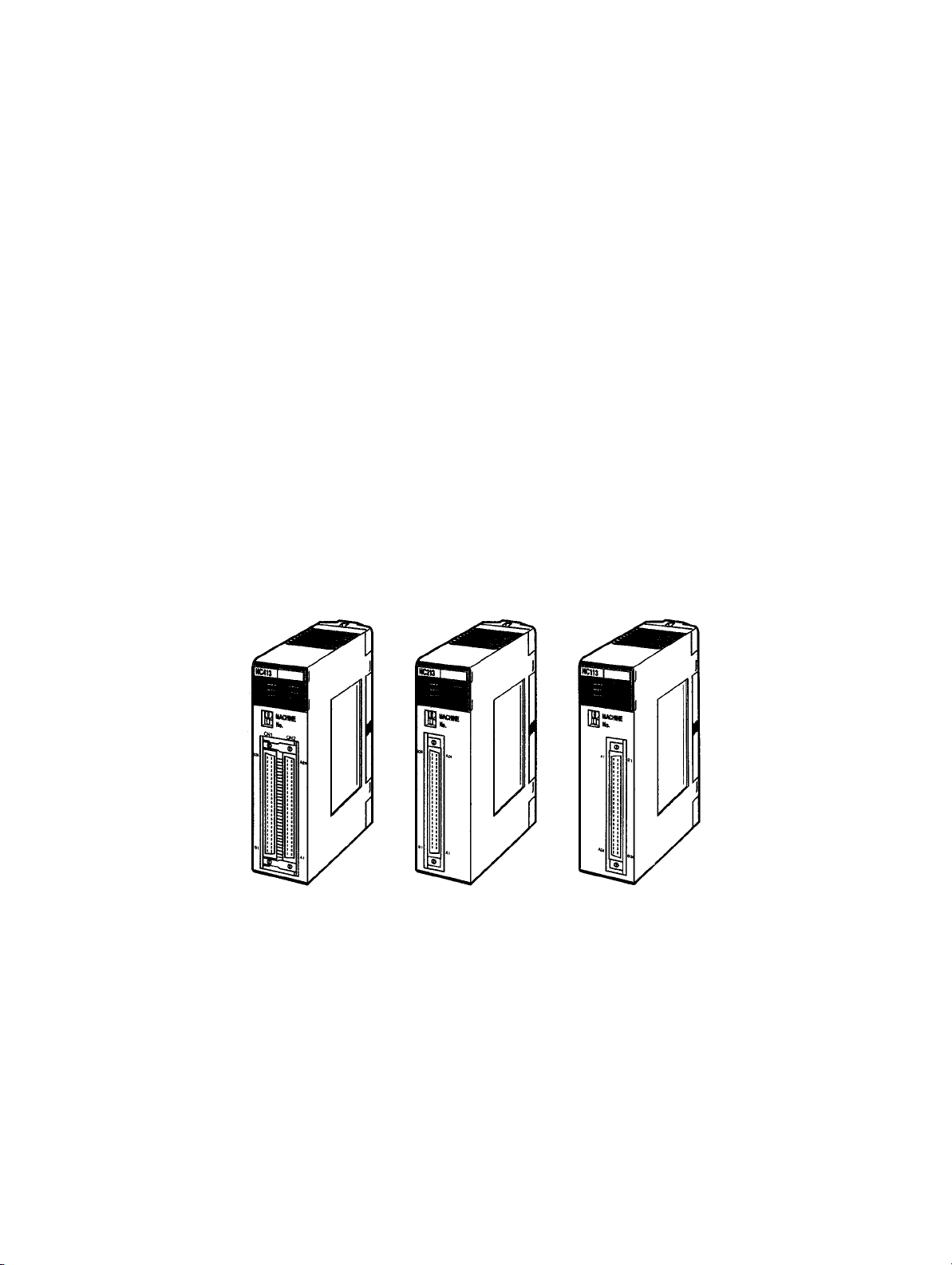
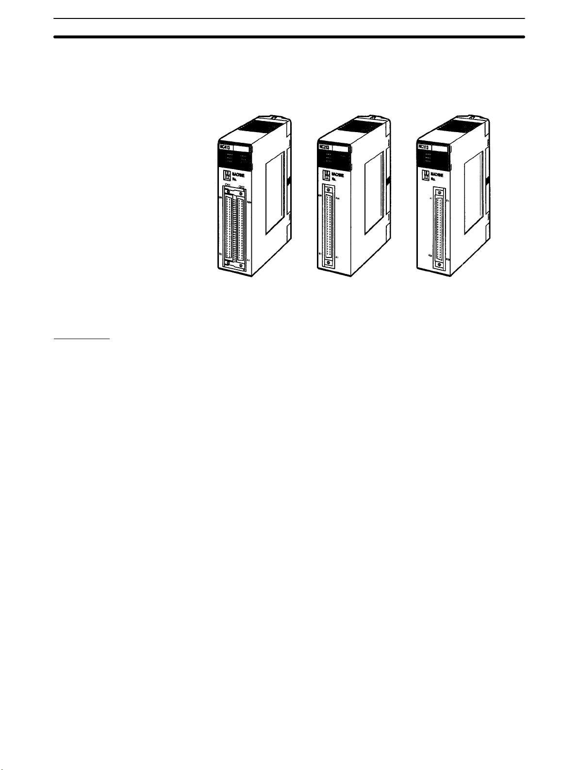
Position Control Unit
1-1SectionFeatures
C200HW-NC413
(4-axis control)
These Position Control Units are C200HX/HG/HE-series and C200H/HS-series
Special I/O Units. The Units receive instructions from the Programmable Controller’s IR area and output pulse trains to various motor drivers for positioning.
C200HW-NC213
(2-axis control)
C200HW-NC113
(1-axis control)
Functions
Motor Driver Selectable
by Axis Unit
Number of Control Axes
and Control Capacity
Memory Operation and
Direct Operation
Interrupt Feeding
High-speed Response
Compact Size
The operating mode can be set by axis unit, so it is possible to select the motor
driver by axis unit. The Position Control Unit outputs pulse trains, so it can easily
be connected to the following motor drivers.
• Stepping motor driver
• Servomotor drivers with pulse input.
The Position Control Unit is available with one, two, or four control axes. With the
two-axis model, the two axes can either be used together for linear interpolation
or they can be operated independently. With the four-axis model, up to four axes
can be used together for linear interpolation or the axes can all be operated independently.
There are two different control methods. The first is memory operation, in which
the data required for positioning is transferred to the Position Control Unit and
then specified for position control, and the second is direct operation, in which
the target position and target speed are set each time from the Programmable
Controller.
When an interrupt is input during pulse output, positioning is continued for only
the specified number of pulses and then stopped.
The Position Control Unit responds to instructions from the Programmable Controller within 10 ms. (This applies to the C200HW-NC113.)
The single-axis, two-axis, and four-axis models are all one size, so space efficiency can be maximized by using multi-axis control with the two-axis and fouraxis models.
Special Support Tool
(SYSMAC-NCT)
2
A special support tool, SYSMAC-NCT, that runs on Windows 95 can be used
with C200HX/HG/HE-series Programmable Controllers. The SYSMAC-NCT
Support Tool can be used for writing data created or edited at a personal computer to the PCU, for reading data from the PCU, and for saving or printing out
data. It also enables the monitoring of status such as I/O and positioning
sequence numbers during execution. For details on operating this Support Tool,
refer to the SYSMAC-NCT Support Tool Operation Manual.
Page 16

1-1SectionFeatures
The SYSMAC-NCT Support Tool can only be used to access PCUs mounted on
a CPU Rack or an Expansion I/O Rack. It cannot access PCUs mounted on
Slave Racks. The SYSMAC-NCT Support Tool cannot be used with
C200H/C200HS CPU Units.
Data Capacity and
Backup
High-speed Data Transfer
The amounts of data that can be set for memory operation are shown in the following table:
Type of data Number of data items per axis
Positioning sequences, speeds, positions 100
Acceleration times, deceleration times 9
Dwell times 19
Zones 3
These data items are transferred to the PCU for use. Once they have been transferred to the PCU they can be saved to the PCU’s flash memory, so there is no
need for battery maintenance.
Note There is a limit to the service life of the flash memory. A total of up to 100,000 data
saving operations can be performed.
With C200HX/HG/HE-series Programmable Controllers, not only can data be
transferred by means of data transfer bits and SYSMAC-NCT Support Tool, but
high-speed data transfers can also be performed by means of the Intelligent I/O
Write (IOWR) and Intelligent I/O Read (IORD) instructions.
3
Page 17
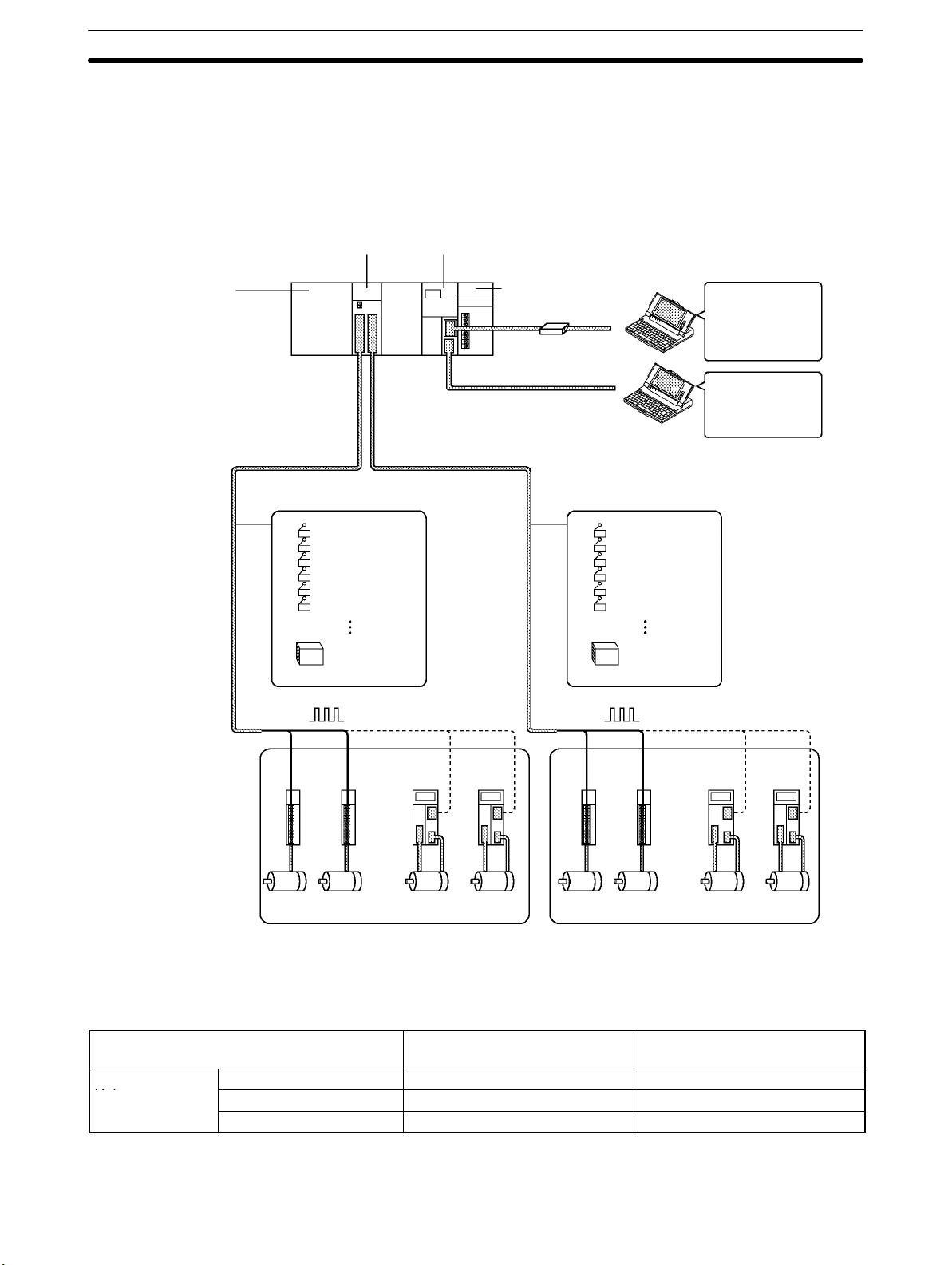
1-2 System Configuration
The Position Control Unit receives control signals (CW limit, CCW limit, origin,
origin proximity, emergency stop, and external interrupt input signals) from
devices and a control panel, and outputs pulse trains to stepping motor drivers
and servomotor drivers.
C200HW-NC413 System Configuration Example
C200HW-NC413
Position Control Unit
C200HX/HG/HE
CPU Unit
1-2SectionSystem Configuration
C200HW-BCjj
Backplane
External input signals
CCW limit
CW limit
Origin
Origin Proximity
Emergency stop
External interrupt
Pulse
output
24-VDC power
supply for I/F
Power Supply Unit
Tool Bus
Host Link
External input signals
Pulse
output
CCW limit
CW limit
Origin
Origin Proximity
Emergency stop
External interrupt
24-VDC power
supply for I/F
SYSMAC Support
Software:
Ladder program
creation and transfer,
monitoring, file
management, etc.
SYSMAC-NCT:
Data creation and
monitoring, PCU
monitoring, file
management, etc.
Number of Usable Units
Item C200H, C200HS, C200HE,
Number of usable
Units
C200HW-NC113 10 max. 16 max.
C200HW-NC213 10 max. 16 max.
C200HW-NC413 5 max. 8 max.
Stepping
Motor
Drivers
Servomotor
Drivers
Or
ServomotorsStepping Motors
Stepping
Motor
Drivers
Or
Stepping Motors
Servomotor
Drivers
Servomotors
The Position Control Unit belongs to the SYSMAC C200H, C200HS, and
C200HX/HG/HE Special I/O Unit group. The numbers of Special I/O Units
(including PC Link Units) that can be mounted to a single CPU Unit are shown in
the following table.
C200HX/HG-CPU5j/6j-(Z)E
C200HX/HG-CPU3j/4j-(Z)E
• For details on the particular Units that belong to each of the Special I/O Unit
groups, refer to the appropriate Programmable Controller operation manual.
4
Page 18
1-2SectionSystem Configuration
• There are restrictions on the maximum current provided to each Rack and the
the current consumption for each Unit. For details, refer to the appropriate Programmable Controller operation manual.
• There are restrictions on the use of Remote I/O Slave Racks. These restric-
tions are explained in Restrictions on Using Remote I/O Slave Racks below.
Restrictions on Using
Remote I/O Slave Racks
As shown in the following table, the number of Special I/O Units that can be used
on a single Remote I/O Slave Rack is determined by the the particular Special
I/O Unit group (A, B, C, or D).
Group A Group B Group C Group D
Units in
group
Number of
Units that
can be used
High-speed Counter
Units
Position Control Unit
(NC111/112)
(NC113/213)
ASCII Units
Analog I/O Units
ID Sensor Units
Fuzzy Logic Units
4 Units 8 Units 6 Units 2 Units
High-density I/O Units
Temperature Control
Heat/Cool Temperature
PID Control Units
Cam Positioner Unit
• If Special I/O Units from different groups are to be mixed, then use a combina-
tion that satisfies the following two formulas:
3A + B + 2C + 6D x 12
A + B + C + D x 8
• There are restrictions on the number of Units that can be used with particular
CPU Units. For details, refer to Number of Usable Units described previously.
System Configuration Considerations
• The I/O bits allocated to a particular Special I/O Unit are determined by the unit
number that is set by the switch on the front panel of the Unit, and not by the slot
in which the Unit is mounted.
• With the C200H, do not mount a Position Control Unit in the two slots adjacent
to the CPU Unit. If it is mounted in those slots, it will not be possible to mount
tools such as the Programming Console.
• Special I/O Units cannot be used with C200H Remote I/O Slave Racks that are
connected to Remote I/O Master Racks for other SYSMAC Programmable
Controller models (such as C120, C500, C1000H, and C2000H).
Units
Control Units
Temperature Sensor Units
Voice Unit
Position Control Units
(NC211)
(NC413)
Mounting the Unit
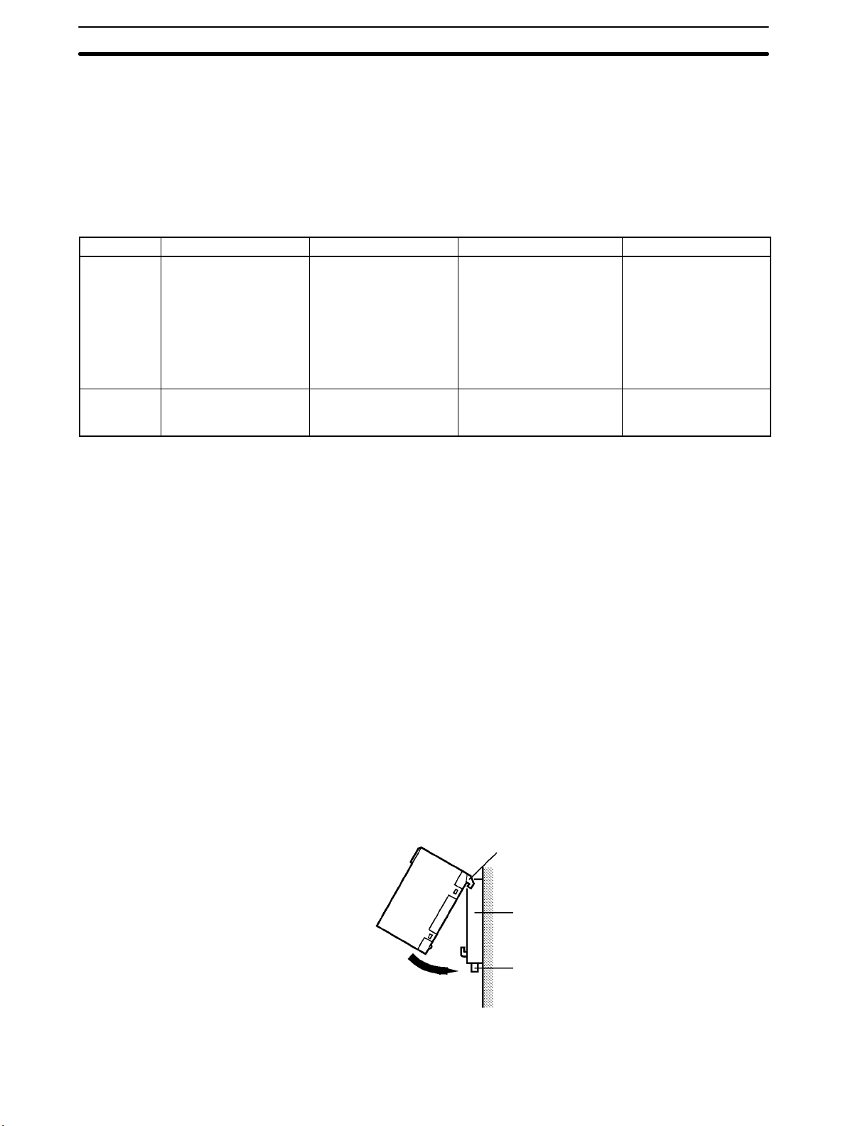
Follow the procedure outlined below to mount the Position Control Unit to the
Backplane.
1, 2, 3... 1. Insert the hook on the upper rear of the Unit into the slot in the Backplane.
Hook
Backplane
Lock lever
2. Carefully insert the Unit into the connector on the Backplane.
5
Page 19
1-2SectionSystem Configuration
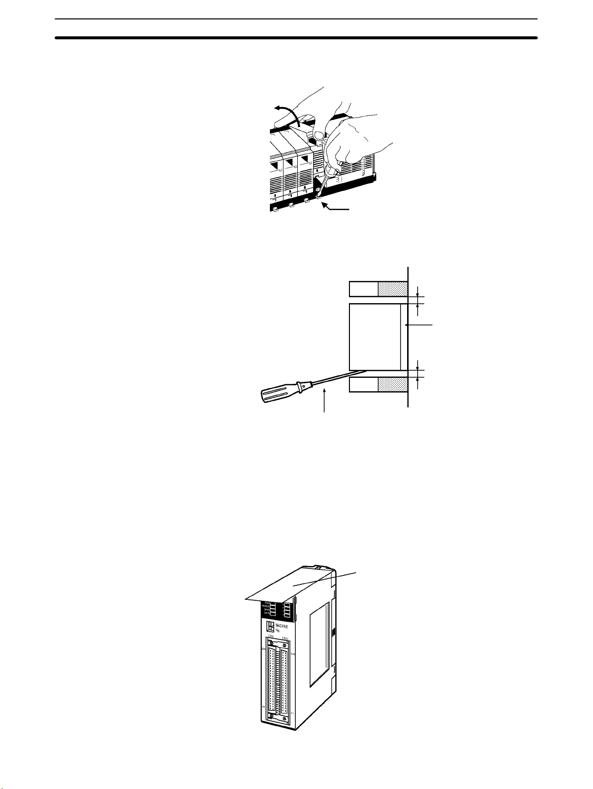
3. To remove the Unit. use an implement such as a screwdriver to press down
on the lock lever and then carefully lift the Unit out.
Lock lever
Note When installing Units on a Rack, leave adequate space for mounting and remov-
ing the Units as shown in the following diagram.
20 mm min.
Precautions When Handling the Unit
• Before installing or disconnecting the Unit or connecting cable, be sure to first
turn off both the Programmable Controller and the power supply.
• To minimize any influence from noise, place I/O wiring, high-voltage lines, and
power lines in separate ducts.
• Wire clippings tend to get scattered around during wiring, so leave the label in
place on top of the Unit to prevent any clippings from getting inside the Unit.
Once the wiring has been completed, be sure to remove the label to provide
ventilation.
Backplane
20 mm min.
Flathead screwdriver
Remove the label after
completing the wiring.
6
Page 20
1-3 Basic Operations
The C200HW-NC113 (one axis), C200HW-NC213 (two axes), and C200HWNC413 (four axes) Position Control Units are designed for use with C200HX/
HG/HE-series and C200H/C200HS-series systems.
1-3-1 Position Control
Positioning can be executed with either an absolute value (i.e., to an absolute
position from the origin) or with an incremental value (i.e., to a relative position
from the present position).
There are two methods for positioning: memory operation and direct operation.
Interrupt feeding, in which operation proceeds for the specified amount after an
interrupt input, is also possible.
1-3SectionBasic Operations
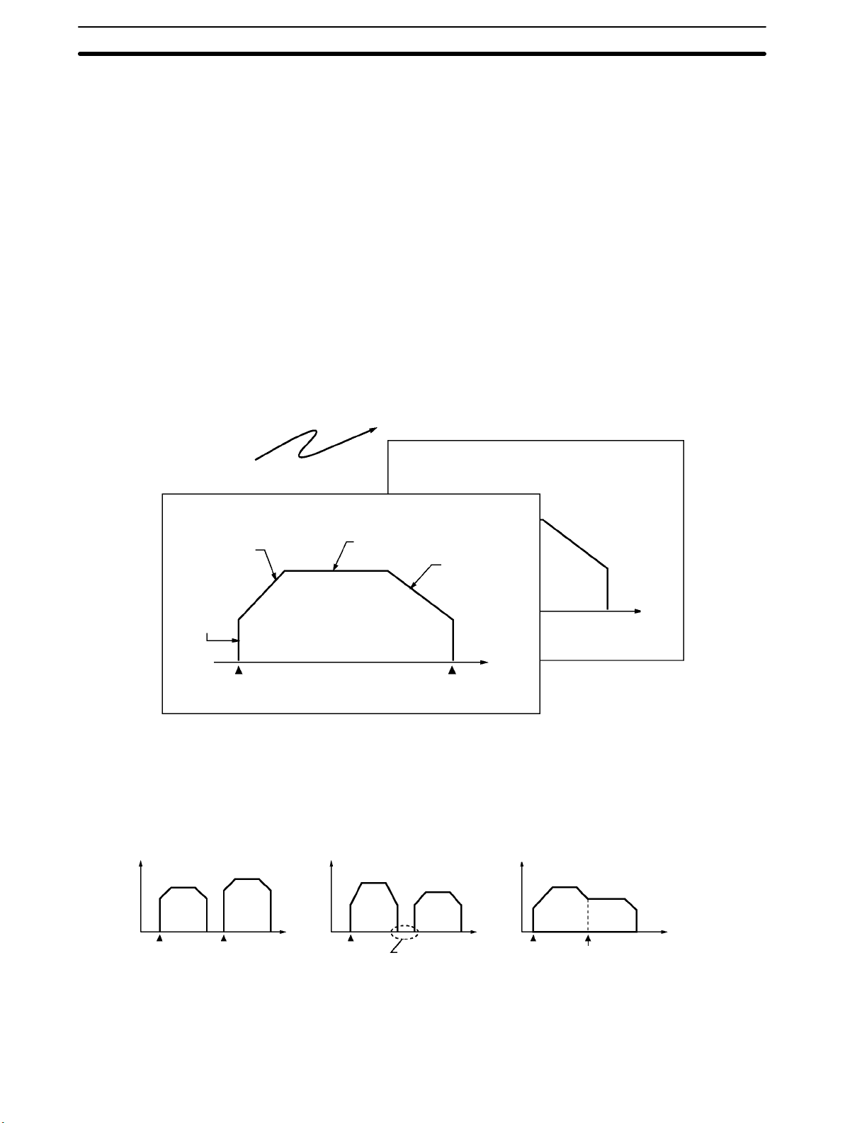
Memory Operation
Positioning sequence #0
Acceleration time number
Initial speed
number
With memory operation, positioning sequences (i.e., individual positioning
operations, which include data such as positions and speeds) are transferred to
the Position Control Unit in advance, and then positioning is executed from the
Programmable Controller by specifying those positioning sequences by number.
Executed in order
Start Target position
Positioning sequence #99
Target speed number
Deceleration time
number
Position
Position
Terminating Positioning Automatic Positioning Continuous Positioning
Pulse output Pulse output Pulse output
#0 #1
Start Start
Direct Operation
Depending on the completion code that is set, positioning sequences can be
executed using terminating positioning, automatic positioning, or continuous
positioning. In the following illustrations, “#0” and “#1” indicate positioning
sequence numbers.
#0
Time
Start
#1
Time
Pauses for length of
dwell time that is set.
#0
Start Does not stop.
#1
Time
With direct operation, positions and speeds are set in allocated areas in the Programmable Controller’s DM and EM areas, and positioning is executed using
that data.
7
Page 21
1-3SectionBasic Operations
Interrupt Feeding
1-3-2 Speed Control
When an interrupt input signal is received, positioning is continued for the specified amount of pulses and then stopped.
Interrupt input signal
Speed
Specified amount
of pulses
Time
When a start is executed once, pulses are continuously output at a constant rate.
The pattern depends on the completion code that is set for “memory operation”
positioning sequences. To stop the sequence, use the STOP command.
Speed
STOP
1-3-3 Other Operations
Origin Search
Jogging
Teaching
The origin search operation finds the origin for the designated axis.
The jogging operation moves a specified axis at a designated speed and then
stops it.
The teaching operation takes the present position for the specified positioning
sequence.
Time
Start
Present position
Origin
Specified positioning sequence number
8
Page 22
1-3SectionBasic Operations
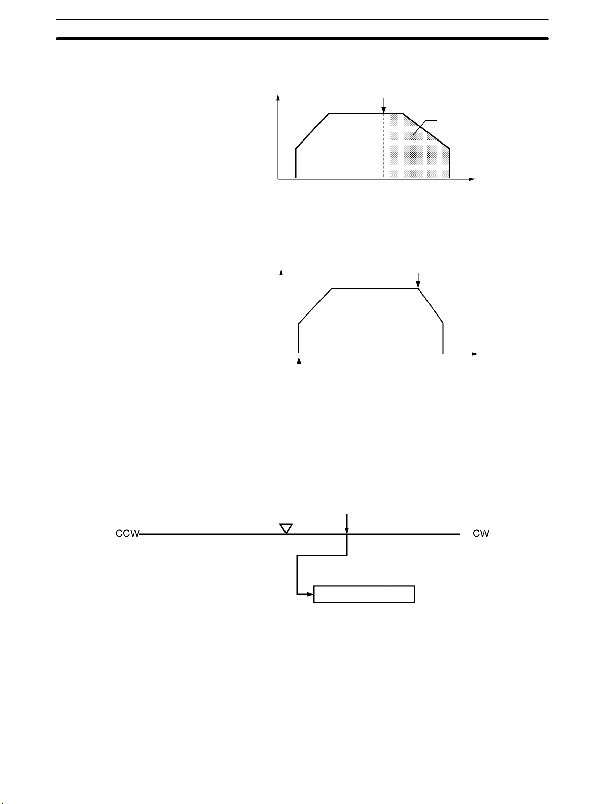
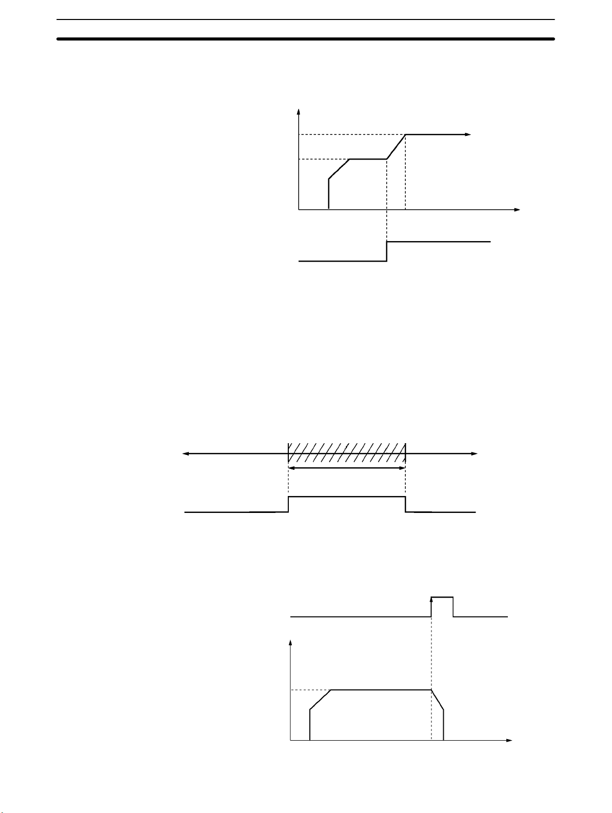
Override
Changing the Present
Position
Backlash Compensation
When the override is enabled during positioning, the target speed is changed to
the override speed.
Speed
A x 1.5
Override enable
A
1
0
Override setting: 150%
Time
The PRESENT POSITION CHANGE command changes the present position to
a specified position.
This operation compensates for the amount of mechanical play, or “looseness,”
present in gears.
Zones
Zone Flag
Deceleration Stop
A zone is a range of positions which can be defined so that flags are turned ON
whenever the present position is within the range.
CCW CW
Zone setting
ON
OFF
The STOP command decelerates positioning to a stop.
STOP
Speed
1
0
Time
9
Page 23

1-3SectionBasic Operations
The C200HW-NC113/NC213/NC413 Position Control Unit’s operations are as
follows:
PCU operations Position control Memory
operation
Direct operation
Interrupt feeding
Speed control
Other operations Origin search
Independent
Automatic
Continuous
Jogging
Teaching
Override
Present position
change
Backlash
compensation
Zone setting
Deceleration stop
10
Page 24
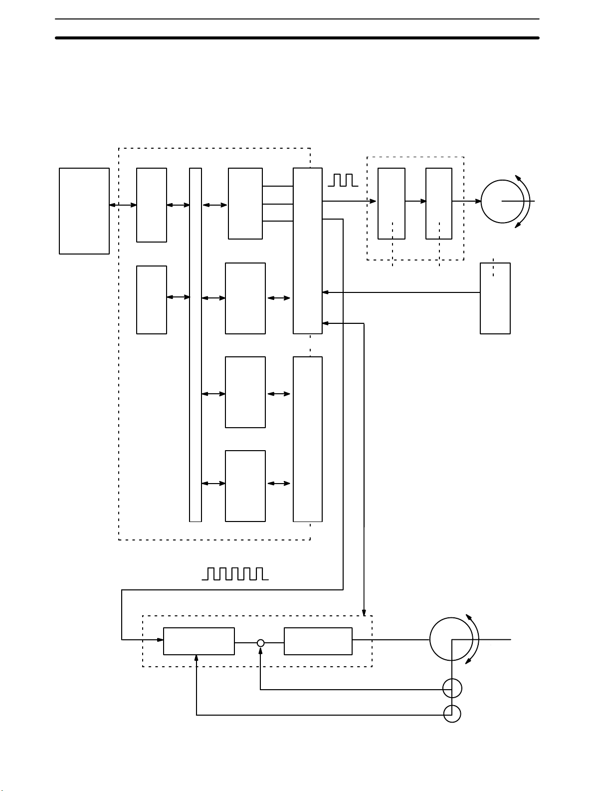
1-4 Control System Principles
1-4-1 Data Flow
C200HW-NC113/NC213/NC413 Position Control Unit
Pulse train
1-4SectionControl System Principles
Stepping motor driver
Stepping motor
SYSMAC
C200HX/HG
/HE
C200HS/Hseries PC
PC
BUS
MPU
I/F
Memory
Pulse
generator
I/O
interface
Pulse
generator
I/O connector
Magnetizing distribution circuit
External
input
Power
amplifier
I/O
interface
I/O connector
Note For the NC113, the circuitry is for just one axis.
Pulse train
Servomotor driver
Error counter Power amplifier
Servomotor
(Positioning output)
Tachogenerator
Rotary encoder
11
Page 25
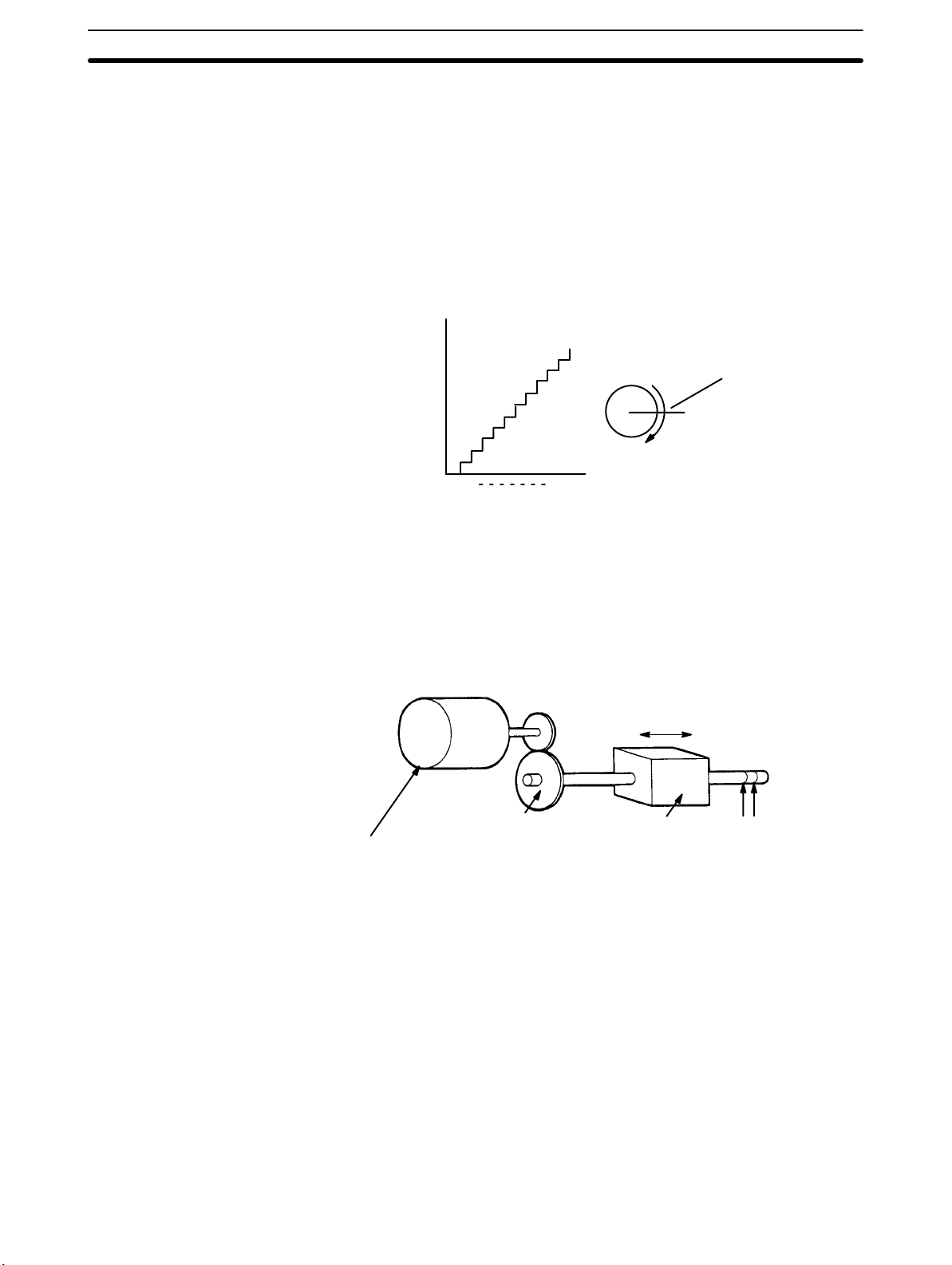
1-4-2 Control System Principles
1-4SectionControl System Principles
Open-Loop System
In an open-loop system, positioning is controlled according to the number of
input pulses that the motor receives, and no position feedback is provided. The
C200HW-NC113/NC213/NC413 PCUs all employ pulse-output-type open-loop
systems, and the most commonly used motor for this type of control system is a
stepping motor. The angle of rotation of a stepping motor can be controlled
through the number of pulse signals supplied to the motor driver. The number of
rotations of the stepping motor is proportional to the number of pulses supplied
by the PCU, and the rotational speed of the stepping motor is proportional to the
frequency of the pulse train.
Angle of
rotation
1 2 n
Positioning pulses
1-4-3 Basic Positioning System Design
The following diagram and parameters illustrate a simplified positioning system.
M : Reduction ratio
P : Feed screw pitch (mm/revolution)
V : Feed velocity of object being positioned (mm/s)
: Stepping angle per pulse (degree/pulse)
θ
s
Angle of rotation
Positioning output
N
Stepping motor
Reduction gear
M
Object being
positioned
V
Feed screw pitch
P
The positioning accuracy in mm/pulse is computed as follows:
Positioning accuracy = P/(pulses per revolution x M)
= P/((360/ θ
= (P x θ
) x M))
s
)/(360 x M)
s
The required pulse frequency from the PCU (pulses/second) is computed as follows:
Pulse frequency = V/Positioning accuracy
= (360 x M x V)/(P x θ
)
s
And the required number of pulses to feed an object by a distance L in mm is
computed as follows:
Number of pulses = L/Positioning accuracy
= (360 x M x L)/(P x θ
)
s
12
Page 26
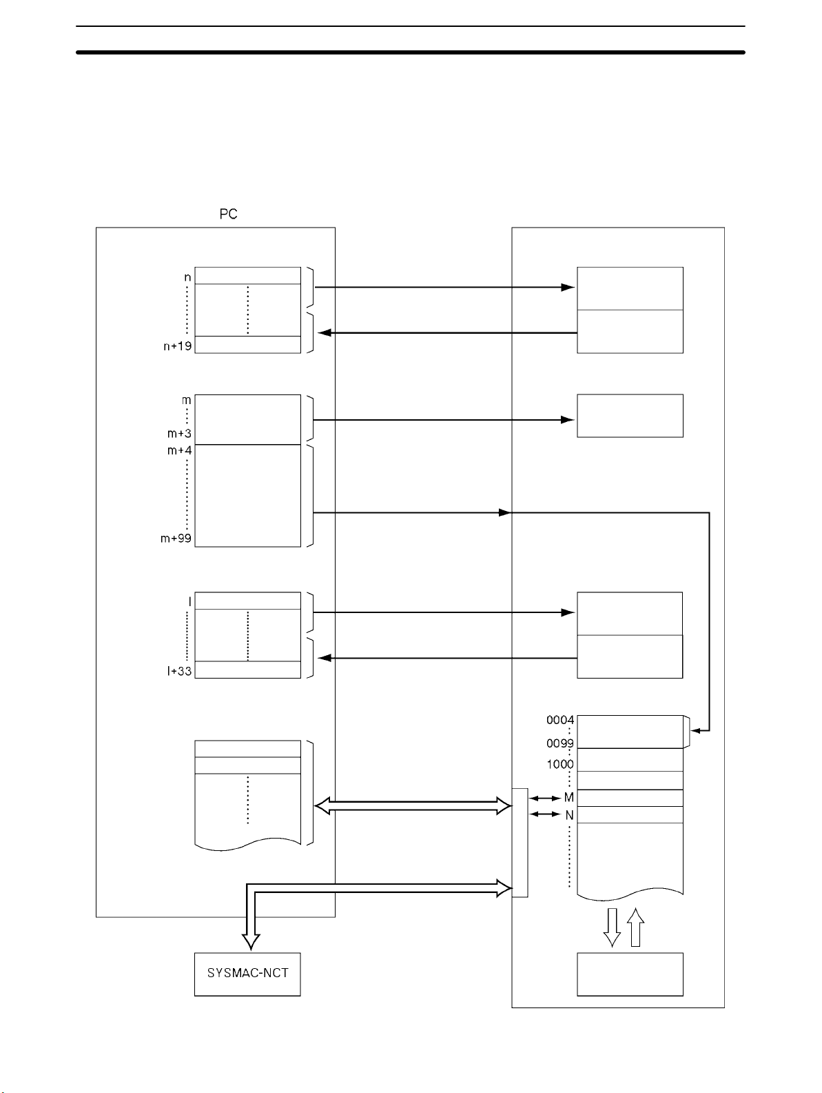
1-5 Exchanging Data
The Position Control Unit exchanges data with the Programmable Controller as
shown in the following diagram. This explanation is provided using the
C200HW-NC413 as an example. The size of the allocated areas differs with the
NC113 and NC213. For details regarding the data areas for the various PCUs,
refer to Section 4 Data Areas.
Operating Memory Area
IR area
Parameter area
I/O refresh
(Operation commands, data
transfer commands, etc.)
I/O refresh (PCU status)
1-5SectionExchanging Data
PCU
Command
interpretation
Status
DM area
DM or EM area
DM or EM area
Common
parameters
Axis parameters
Operating Data Area
Data transfer area
Address M data
Address N data
At power-up or restart
(Common parameters)
At power-up or restart
(Axis parameters)
I/O refresh
(Data transfer and operation
command information)
I/O refresh (PCU status)
When data transfer
commands are executed.
When IOWR or IORD is
executed.
Address
Common
parameters
Data transfer and
operation command
information
Status
Internal memory
Axis parameters
(Data for positioning)
When data is transferred
Saving
data
Power-up
or restart
Flash memory
13
Page 27

1-5-1 Explanation
1-5SectionExchanging Data
Note The axis parameter data stored in addresses 0004 to 0099 can be transferred
from words (m+4) through (m+99) of the DM area, and data can also be transferred for the data transfer area at the Programmable Controller. Moreover, data
can be saved to the flash memory.
The explanations provided here use the C200HW-NC413 PCU as an example.
With the NC213 and NC113, the sizes of the various areas differ depending on
the number of axes. For details, refer to Section 4 Data Areas.
Operating Memory Area
(IR Area)
Parameter Area
(DM Area)
Operating Data Area
The PCU occupies 20 words of the Special I/O area within the Programmable
Controller’s IR area. Of these, eight words are used during I/O refreshing for outputting information related to instructions for operations such as transferring
data from the Programmable Controller to the PCU. The remaining 12 words are
used for inputting the PCU’s status during I/O refreshing.
The PCU occupies 100 words of the Special I/O Unit data area within the Programmable Controller’s DM area. When the PCU is powered up or restarted,
common parameters and axis parameters related to control are transferred to
the PCU. The axis parameters are stored in the PCU’s internal RAM by address.
It is also possible, when the PCU is powered up or restarted, to use axis parameters previously stored in the PCU’s internal flash memory, without having them
transferred from the Programmable Controller. The selection as to which of
these two methods to use is made by a common parameter setting. For details,
refer to 4-2 Common Parameter Area.
Note The common parameter area settings are required when the PCU is used. If
these settings are not made, a common parameter error (error codes 0010 to
0013) will be generated.
Depending on a common parameters setting, 34 words are reserved in the Programmable Controller’s data areas. Of these, 26 words are used during I/O
refreshing for outputting information related to data transfers from the Programmable Controller to the PCU, and information used for operations. The remaining eight words are used for inputting the PCU’s status during I/O refreshing.
Data Transfer Area
Internal Memory and
Flash Memory
14
When data is transferred according to the data transfer information set in the
operating data area, only the portion of data transferred is used. When the data
transfer instructions, Intelligent I/O Write (IOWR) and Intelligent I/O Read
(IORD), are executed, the positioning data is transferred to the PCU.
Data in internal memory can be saved to flash memory by executing a data save
instruction from the Programmable Controller. The saved data is automatically
written to the internal memory when the PCU is powered up or restarted. However, whether axis parameters are read from the parameter area (DM) or from
flash memory is determined by a common parameters setting.
Page 28
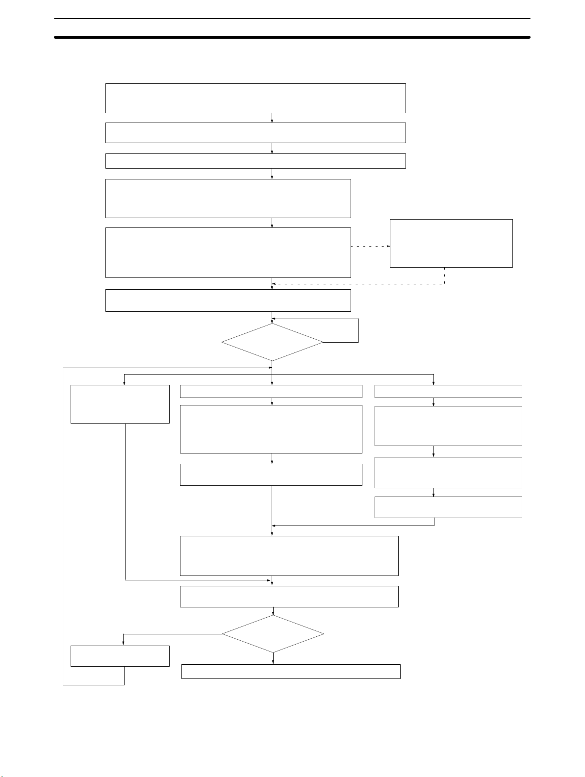
1-6 Before Operation
Wiring external inputs. (Refer to Section 2 Specifications and Wiring.)
Wire the origin input signal, origin proximity input signal, CW and CCW limit input
signals, emergency stop input signal, and interrupt input signal.
Wiring the motor and motor driver.
Wire the motor and motor driver as described in the installation manual.
Wiring the motor driver and PCU. (Refer to Section 2 Specifications and Wiring.)
Setting common parameters. (Refer to 4-2 Common Parameter
Area.) (See note 1.)
Set the operating data area, the mounting position, and the
parameters.
Setting axis parameters. (Refer to 4-3 Axis Parameter Area.) (See
note 2.)
Set the data required for PCU control, the I/O settings, the operation mode, the origin search method, the origin search speed, the
acceleration/deceleration curve, the CW and CCW limit signals, etc.
Re-powering or restarting the PCU. (See note 5.)
The common and axis parameter settings will go into effect.
1-6SectionBefore Operation
Saving axis parameters.
(Refer to 5-7 Saving Data.)
If setting axis parameters by
means of a data transfer, save
the settings to flash memory.
Interrupt feeding and
other operations.
(Refer to Section 9
Other Operations.)
Busy Flag
(See note 6.)
OFF
(When using direct operation.)
Setting the operating data area.
(Refer to 4-1 Overall Structure, 4-5 Operating
Data Area)
Set the positions, speeds, and acceleration/deceleration times
Creating the ladder program.
(Refer to Section 7 Direct Operation.)
Origin search. (Refer to Section 6 Defining the Origin.)
(See note 4.)
Executing direct operation, memory operation (Refer to
Section 7 Direct Operation, Section 8 Memory Operation.)
Trial operation, debugging. (Refer to Section 11 Trouble-
shooting.) (See note 5.)
ON
(When using memory operation.)
Transferring data. (Refer to Section 5
Transferring and Saving Data.)
Transfer to the PCU the data to be
used for memory operation.
Saving the data (Refer to 5-1 Transfer-
ring and Saving Data, 5-7 Saving
Data.) (See note 3.)
Creating the ladder program.
(Refer to Section 8 Memory Operation.)
Correcting the data and
the ladder program.
NG
Operation. (Refer to Section 11 Troubleshooting.)
Trial operation
(See note 5.)
OK
Note 1. These settings are required when first using the PCU, or when changing the
operating data area, the mounting position, or the parameter settings.
15
Page 29

1-6SectionBefore Operation
2. The user can select whether to use the axis parameters set in Data Memory
or the axis parameters saved at the PCU.
3. All saved data is automatically read to the PCU’s internal memory when the
PCU is powered up. If the common parameters are set so that data saved at
the PCU is used, then the axis parameters will be automatically read at power-up.
4. For operations that cannot be performed when the origin is not established,
it will be necessary to first execute an origin search or a present position
change to establish the origin.
5. For the operational flow when an error or alarm is generated, refer to Section
11 Troubleshooting.
6. When powering up or restarting the PCU, wait for the X-axis Busy Flag to
turn OFF before executing any commands.
16
Page 30

Specifications and Wiring
This section provides the Position Control Unit’s specifications and explains the wiring.
2-1 Specifications 18. . . . . . . . . . . . . . . . . . . . . . . . . . . . . . . . . . . . . . . . . . . . . . . . . . . . . . . . . . . .
2-1-1 General Specifications 18. . . . . . . . . . . . . . . . . . . . . . . . . . . . . . . . . . . . . . . . . . . . . .
2-1-2 Operations and Performance Specifications 18. . . . . . . . . . . . . . . . . . . . . . . . . . . . .
2-1-3 I/O Electrical Specifications 19. . . . . . . . . . . . . . . . . . . . . . . . . . . . . . . . . . . . . . . . .
2-1-4 Dimensions (Unit: mm) 20. . . . . . . . . . . . . . . . . . . . . . . . . . . . . . . . . . . . . . . . . . . . .
2-2 Components 21. . . . . . . . . . . . . . . . . . . . . . . . . . . . . . . . . . . . . . . . . . . . . . . . . . . . . . . . . . . . .
2-3 External I/O Circuitry 24. . . . . . . . . . . . . . . . . . . . . . . . . . . . . . . . . . . . . . . . . . . . . . . . . . . . .
2-3-1 Connector Pin Arrangement 24. . . . . . . . . . . . . . . . . . . . . . . . . . . . . . . . . . . . . . . . .
2-3-2 External I/O Connector Arrangement 25. . . . . . . . . . . . . . . . . . . . . . . . . . . . . . . . . .
2-3-3 I/O Circuitry 27. . . . . . . . . . . . . . . . . . . . . . . . . . . . . . . . . . . . . . . . . . . . . . . . . . . . . .
2-4 Connecting External I/O 30. . . . . . . . . . . . . . . . . . . . . . . . . . . . . . . . . . . . . . . . . . . . . . . . . . .
2-4-1 Output Connection Examples 30. . . . . . . . . . . . . . . . . . . . . . . . . . . . . . . . . . . . . . . .
2-4-2 Input Connection Examples 33. . . . . . . . . . . . . . . . . . . . . . . . . . . . . . . . . . . . . . . . . .
2-4-3 Connecting Origin and Positioning Completed Input Signals 35. . . . . . . . . . . . . . . .
2-4-4 Wiring Precautions 36. . . . . . . . . . . . . . . . . . . . . . . . . . . . . . . . . . . . . . . . . . . . . . . . .
2-5 Connections in Each Operating Mode 37. . . . . . . . . . . . . . . . . . . . . . . . . . . . . . . . . . . . . . . . .
2-6 Connection of Unused Axes 45. . . . . . . . . . . . . . . . . . . . . . . . . . . . . . . . . . . . . . . . . . . . . . . . .
2-6-1 C200HW-NC213 – X Axis Only 45. . . . . . . . . . . . . . . . . . . . . . . . . . . . . . . . . . . . . .
2-7 Servo Relay Unit 45. . . . . . . . . . . . . . . . . . . . . . . . . . . . . . . . . . . . . . . . . . . . . . . . . . . . . . . . .
SECTION 2
17
Page 31

2-1 Specifications
q
p
2-1-1 General Specifications
The general specifications conform to the specifications for the SYSMAC
C200H, C200HS, and C200HX/HG/HE.
2-1-2 Operations and Performance Specifications
2-1SectionSpecifications
Item
C200HW-NC113 C200HW-NC213 C200HW-NC413
Applicable PC models C200HX/HG/HE-series and C200HS/H-series
I/O requirements
Controlled driver Pulse-train input-type servomotor driver or stepping motor driver
Control
Control unit Pulse
Positioning operations Two types: memory operation and direct operation
Positions
Speeds
Acceleration and
deceleration times
Functions and
settings
Words 5 words 10 words 20 words
Slots 1 slot
Control system Open-loop control by pulse train output
Number of control
axes
Independent 1 axis 2 independent axes 4 independent axes
Linear interpolation None 2 axes max. 4 axes max.
Speed control 1 axis 2 independent axes 4 independent axes
Interrupt feeding 1 axis 2 independent axes 4 independent axes
Range –9,999,999 to 9,999,999 pulses
Data items 100/axis
Range 1 pps to 500 Kpps
Data items 100/axis
Range 0 to 250 s, until maximum speed is reached.
Data items 9/axis for acceleration and deceleration each
Origin search Origin proximity input signal: selectable (absent, N.O. or N.C. contact).
Jogging Jogging can be executed at a specified speed.
Dwell times 19/axis can be set from 0 to 9.99 s (unit: 0.01 s).
Acceleration/
deceleration curves
Zones Zone Flag turns ON when present position is within a specified zone.
Software limit Can be set within a range of –9,999,999 to 9,999,999 pulses.
Backlash
compensation
Teaching With a command from the PC, the present position can be taken as the
Deceleration stop The STOP command causes positioning to decelerate to a stop
Emergency stop Pulse outputs are stopped by an external emergency stop command.
1 axis 2 axes 4 axes
Origin input signal: selectable (N.O. or N.C. contact)
Origin compensation: –9,999,999 to 9,999,999 pulses
Origin search speed: High-speed or proximity-speed can be set.
Origin search method: May be set to stop upon origin input signal after
proximity input signal has turned ON, to stop upon origin input signal
after proximity input signal has turned OFF, to stop upon origin input
signal without using proximity input signal, or to stop upon origin input
signal after limit input signal has turned OFF.
N.O. = Normally open
N.C. = Normally closed
Trapezoidal or S-curve (Can be set separately for each axis.)
Three zones can be set for each axis.
0 to 9,999 pulses. Compensation speed can also be set.
position data.
according to the specified deceleration time.
Model
18
Page 32

Item ModelItem
se gs
s ope co ec o
spec ca o s
0sa
sede
s g a co espo d g o
0sa
C200HW-NC413C200HW-NC213C200HW-NC113
Functions and
settings
External I/O
Pulse output distribution period 4 ms
Response time Refer to Appendix A Data Calculation Standards.
Self-diagnostic function Flash memory check, memory loss check, I/O bus check
Error detection function Overtravel, CPU error, software limit over, emergency stop
Internal current consumption (provided from
Backplane)
Dimensions (one size) 130 (H) x 34.5 (W) x 100.5 (D)
Weight (excluding connectors) 250 g max. 300 g max. 350 g max.
Present position
change
Override When the override enabling command is executed during positioning,
Data saving 1) Saving to flash memory. (Can be written 100,000 times.)
Inputs Prepare the following inputs for each axis:
Outputs Prepare the following outputs for each axis:
The PRESENT POSITION CHANGE command can be used to change
the present position to a specified value.
the target speed is changed by applying the override coefficient.
Possible to set to a value from 1 to 999% (by an increment of 1%)
2) Reading to PC area by data reading instruction.
3) Reading by SYSMAC-NCT Support Tool and saving to personal
computer hard disk or floppy disk.
CW and CCW limit input signals, origin proximity input signal, origin
input signal, emergency stop input signal, positioning completed signal,
interrupt input signal
Pulse outputs (open collector outputs)
CW/CCW pulses, pulse outputs and direction outputs can be switched.
Either error counter reset or origin-adjustment command outputs can
be selected depending on the mode.
5 VDC at 300 mA
max.
5 VDC at 300 mA
max.
5 VDC at 500 mA
max.
2-1SectionSpecifications
2-1-3 I/O Electrical Specifications
Input Specifications
Voltage 24 VDC ±10%
Current 4.3 mA (at 24 V) typ.
ON voltage 17.4 VDC min.
OFF voltage 5.0 VDC max.
ON response time 1 ms max. (0.1 ms max.: Interrupt input)
OFF response time 1 ms max.
Origin-signal Input
Specifications
Item Connection
External signal
is open-collector
signal
External signal
is line-driver
signal
Item Specification
Specification Response
Terminal
X/Z Axis A15
A14
Y/U Axis B15
B14
X/Z Axis A16
A14
Y/U Axis B16
B14
Conform to above input
specifications
Signal is a line-driver output
signal corresponding to
Am26LS31
Time
N.O. contact:
0.1 ms max.
N.C. contact:
1 ms max.
N.O. contact:
0.1 ms max.
N.C. contact:
1 ms max.
19
Page 33

2-1SectionSpecifications
Output Specifications
CW/CCW Pulse Output
Specifications
Maximum switching
capacity
Minimum switching
capacity
Leakage current 0.1 mA max.
Residual voltage 0.6 V max.
External power supply 24 VDC ±10% NC413: 90 mA max.
The minimum CW/CCW pulse widths are shown below.
The OFF and ON refer to the output transistor.
Item Specification
30 mA at 4.75 to 26.4 VDC (NPN open collector)
(16 mA: Terminals with 1.6-kΩ limit resistance)
7 mA at 4.75 to 26.4 VDC (NPN open collector)
NC213: 50 mA max.
NC113: 30 mA max.
The output transistor is ON at level “L.”
B
OFF
90%
10%
ON
A
Pulse
frequency
50 Kpps 9.7 µs min. 9.7 µs min. 9.8 µs min. 9.8 µs min. 9.7 µs min. 9.7 µs min. 9.7 µs min. 9.7 µs min.
100 Kpps 4.7 µs min. 4.7 µs min. 4.8 µs min. 4.8 µs min. 4.7 µs min. 4.7 µs min. 4.8 µs min. 4.8 µs min.
200 Kpps 2.3 µs min. 2.3 µs min. 2.3 µs min. 2.3 µs min. 2.2 µs min. 2.2 µs min. 2.3 µs min. 2.3 µs min.
500 Kpps 0.76 µs
7 mA/5 VDC±5% 30 mA/5 VDC±5% 7 mA/24 VDC±10%
A B A B A B A B
0.82 µs
min.
min.
Open or close current / Loaded power-source voltage
(1.6-kΩ resistance)
0.77 µs
min.
0.88 µs
min.
0.74 µs
min.
0.72 µs
min.
16 mA/24 VDC±10%
(1.6-kΩ resistance)
0.76 µs
min.
0.85 µs
min.
Note 1. The load in the above table is the net resistance load, and the connecting
cable impedance with the load is not considered.
2. Due to distortions in pulse waveforms as a result of connecting cable impedance, pulse widths during actual usage may be smaller than those shown in
the above table.
2-1-4 Dimensions (Unit: mm)
Mounted Dimensions
Backplane
Cable
Approx. 230
20
Page 34

2-2 Components
Nomenclature
C200HW-NC413 C200HW-NC213 C200HW-NC113
2-2SectionComponents
LED indicators
Show the PCU’s
operating status.
X/Y axis connector
Connects stepping
motor driver or
servomotor driver.
(2-axis control)
Unit number setting switch
Sets the unit number for the
PCU.
Z/U axis connector
Connects stepping motor
driver or servomotor
driver. (2-axis control)
X, Y axis
connector
X axis
connector
21
Page 35
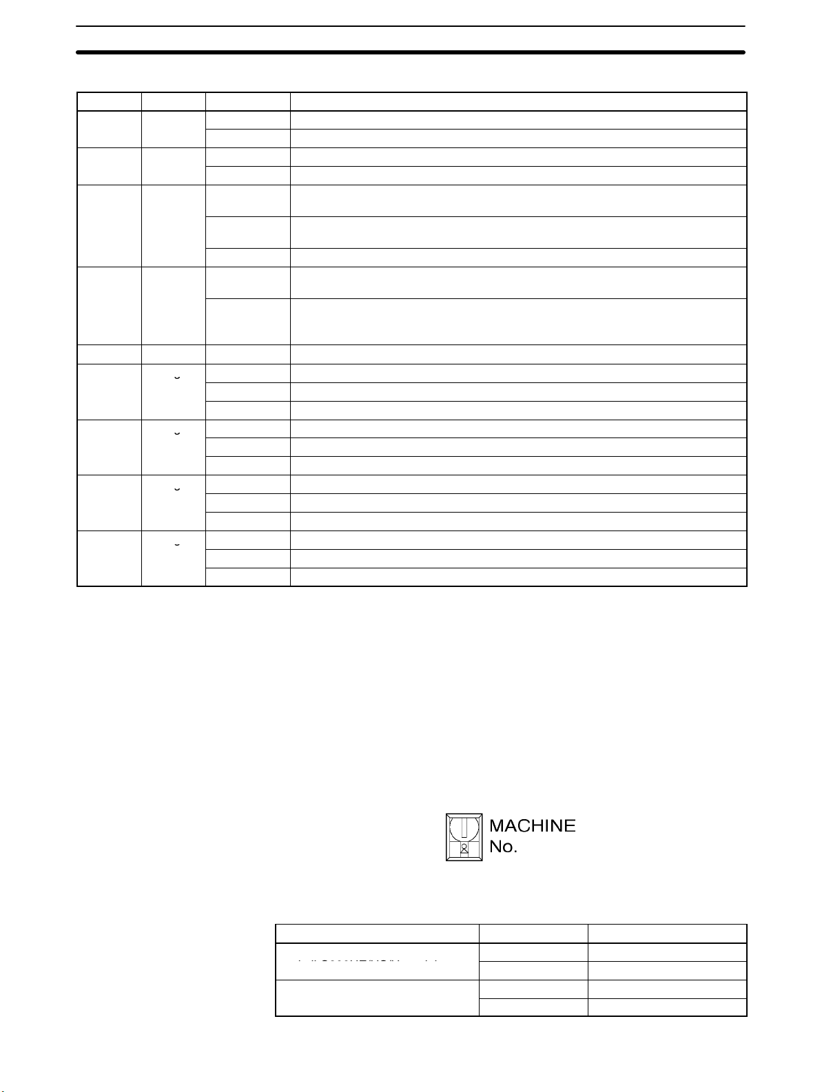
LED Indicators
g
g
g
g
j j
j j
Name Color Status Explanation
RUN Green
ERR Red
SENS Red
DATA Red
DATA Red Not lit None of the above has occurred.
X Orange
Y Orange
Z Orange
U Orange
Lit Lit during normal operation.
Not lit Hardware error, or PC notified of PCU error.
Lit / flashing An error has occurred.
Not lit No error has occurred.
Lit Either a CW/CCW limit signal or an emergency stop input signal is being input. At
this time the LED indicator for the relevant axis (X to U) will flash.
Flashing Either a parameter loss, a data loss, or an operating data area designation error
has occurred.
Not lit None of the above has occurred.
Flashing The check of all data (parameters, positions, etc.) following power up shows that
data is lost or corrupted.
Lit Data is incorrect (e.g., the parameters or positions transferred are out of the
permissible range). At this time the LED indicator for the relevant axis (X to U)
will flash.
Lit Pulses are being output to the X axis (either forward or reverse).
Flashing An error has occurred, such as incorrect cable type for the X axis or faulty data.
Not lit None of the above has occurred.
Lit Pulses are being output to the Y axis (either forward or reverse).
Flashing An error has occurred, such as incorrect cable type for the Y axis or faulty data.
Not lit None of the above has occurred.
Lit Pulses are being output to the Z axis (either forward or reverse).
Flashing An error has occurred, such as incorrect cable type for the Z axis or faulty data.
Not lit None of the above has occurred.
Lit Pulses are being output to the U axis (either forward or reverse).
Flashing An error has occurred, such as incorrect cable type for the U axis or faulty data.
Not lit None of the above has occurred.
2-2SectionComponents
Unit Number Setting
Switch
Note For details regarding errors, refer to Section 11 Troubleshooting.
• For the C200HW-NC213, this applies only to the X axis; for the C200HW-
NC213, it applies only to the X and Y axes.
• When not all of the axes are used for the C200HW-NC213 or C200HW-
NC413, either connect the CW/CCW limit inputs for the unused axes to the
input power supply and turn them ON or set the contact logic to N.O. Connect
the emergency stop to the input common and turn it ON. If it is not connected,
the ERR indicator will light. Operation will be normal, however, for all axes that
are used.
This switch sets the unit number (i.e., the machine number) for the PCU.
The permissible range of unit number settings depends on the type of Programmable Controller and the PCU model, as shown in the following table.
PC type PCU model Setting range
C200HX/HG-CPU3j/4j
and all C200HE/HS/H models
C200HX/HG-CPU5j/6j
NC113/NC213 0 to 9
NC413 0 to 8
NC113/NC213 0 to 9, A to F
NC413 0 to 8, A to E
22
Page 36

Any unit number within the permissible range can be set, as long as it does not
overlap with the unit numbers that are set for any other Special I/O Units
mounted to the same Programmable Controller.
Caution Be sure to turn off the power supply before making the settings.
!
The IR and DM areas are allocated according to the unit numbers that are set.
For details regarding allocated word addresses, refer to the memory area
allocation tables in Section 4 Data Areas.
2-2SectionComponents
23
Page 37

2-3 External I/O Circuitry
2-3-1 Connector Pin Arrangement
X/Y axis X/Y axis X axisZ/U axis
C20HW-NC413 C20HW-NC213 C20HW-NC113
2-3SectionExternal I/O Circuitry
Connector pin arrangement for X and Z axes Connector pin arrangement for Y and U axes
Pin
No.
A1 IN Output power supply, 24 VDC B1 IN Output power supply, 24 VDC
A2 IN Output GND, 24 VDC B2 IN Output GND, 24 VDC
A3 --- Not used B3 --- Not used.
A4 --- Not used B4 --- Not used.
A5 OUT CW pulse output B5 OUT CW pulse output
A6 OUT CW pulse/pulse output with 1.6 kΩ
A7 OUT CCW pulse/direction output B7 OUT CCW pulse/direction output
A8 OUT CCW pulse/direction output with 1.6 kΩ
A9 --- Not used B9 --- Not used.
A10 OUT Error counter reset output Origin-adjustment
A11 OUT Error counter reset output with 1.6 kΩ
A12 IN Positioning completed input signal B12 IN Positioning completed input signal
A13 --- Not used B13 --- Not used.
A14 IN Origin common B14 IN Origin common
A15 IN Origin input signal (24 V) B15 IN Origin input signal (24 V)
A16 IN Origin input signal (5 V) B16 IN Origin input signal (5 V)
A17 --- Not used B17 --- Not used.
A18 --- Not used B18 --- Not used.
A19 IN Interrupt input signal B19 IN Interrupt input signal
A20 IN Emergency stop input signal B20 IN Emergency stop input signal
A21 IN Origin proximity input signal B21 IN Origin proximity input signal
A22 IN CW limit input signal B22 IN CW limit input signal
A23 IN CCW limit input signal B23 IN CCW limit input signal
A24 IN Input common B24 IN Input common
I/O Designation Pin
No.
B6 OUT CW pulse/pulse output with 1.6 kΩ
resistance
B8 OUT CCW pulse/direction output with 1.6 kΩ
resistance
B10 OUT Error counter reset output Origin-adjustment
command output
B11 OUT Error counter reset output with 1.6 kΩ
resistance
Origin-adjustment command output with
1.6KΩ resistance
I/O Designation
resistance
resistance
command output
resistance
Origin-adjustment command output with
1.6KΩ resistance
24
Page 38

Note 1. Use either the 24-V origin input signal or the 5-V origin input signal, but not
both.
2. Use 24 ±10% VDC as the pulse output power supply.
3. The leakage current must be less than 1.0 mA when two-wire-type sensors
are used.
4. Be sure to connect a load to the output terminals. If the load is short-circuited, it will damage the PCU’s internal components.
5. The 24-V output power supply (A1/B1) for all axes and the 24-V output
ground (A2, B2) are connected in the PCU, and are shared by all axes.
6. When installing connectors to the PCU, tighten the connector screws to a
torque of 0.34 N S m.
• The commons for all outputs are connected to the 24-V output ground.
• The commons for all inputs except for the 24-V and 5-V origin input signals and
positioning completed input signals are connected to the input common.
• The positioning completed input signal common is connected to the 24-V out-
put power supply through a diode.
• The origin common is used with either the 24-V or the 5-V origin input signal.
2-3-2 External I/O Connector Arrangement
2-3SectionExternal I/O Circuitry
Wiring Power Lines
Connector Pin Numbers
• The connectors that are included with this Unit are solder-type connectors.
• Use wires with cross-sectional areas of 0.2 mm
2
or less.
• Be careful not to short-circuit neighboring terminals when soldering.
• Cover the soldered part of the wire with insulation tubing.
Insulator
Lead
Connector
Outline of connector
(rear panel)
Pin number marks
(View from soldered side)
25
Page 39

Assembling Connectors Supplied with the Unit
)
M2x8 pan-head screws (two)
Connector
The following connectors (Fujitsu 360 Jack) can be used:
1, 2, 3... 1. FCN-361J048-AU (solder-type)
FCN-360C048-D (connector cover)
2. FCN-363J048 (crimp-type housing)
FCN-363J-AU/S (contact)
FCN-360C048-D (connector cover)
3. FCN-367J048-AU (crimp-type)
2-3SectionExternal I/O Circuitry
M2 nut (four)
M2x6 pan-head screws (two
Cable holder (two)
Case
Screw (two)
Cover Dimensions
Cable holder
26
Page 40
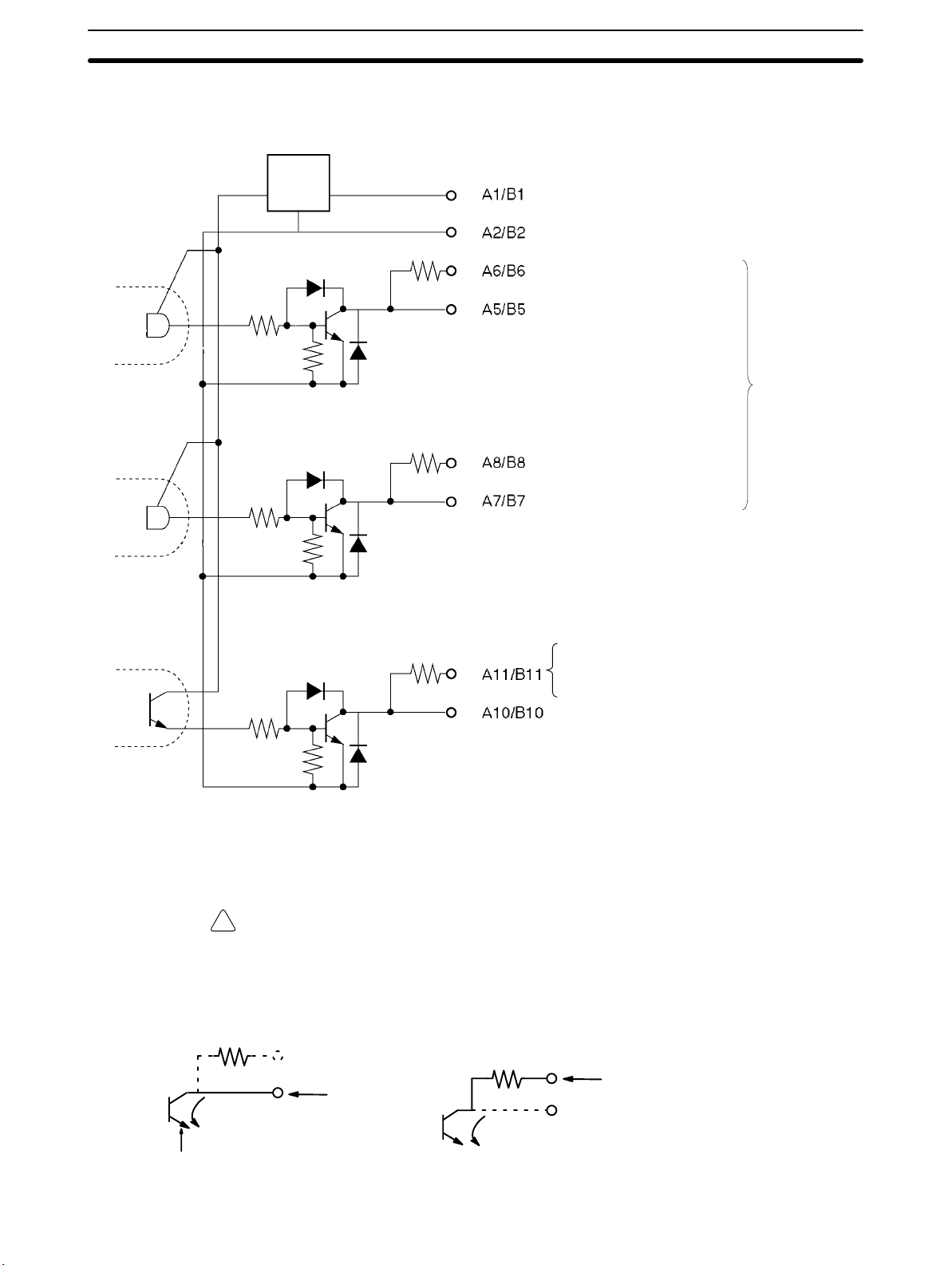
2-3-3 I/O Circuitry
Outputs
Constant
voltage
circuit
2-3SectionExternal I/O Circuitry
Output power supply, 24 VDC
1.6 kΩ (1/2W)
1.6 kΩ (1/2W)
1.6 kΩ (1/2W)
Output GND, 24 VDC
CW pulse/pulse output
(with 1.6 kΩ resistance)
CW pulse output
See
note.
CCW pulse/direction output
(with 1.6 kΩ resistance)
CCW pulse/direction output
Note Output switching depends on the
axis parameter settings. (Refer to
4-3 Axis Parameters Area.)
Error counter reset output (with 1.6 kΩ
resistance)
Origin-adjustment command output (with
1.6 kΩ resistance)
Error counter reset output
Origin-adjustment command output
Output Circuitry
Open collector output
Output transistor
The pulse output and error counter reset circuitry of the Position Control Unit are
provided with two types of terminals: terminals with 1.6 kΩ (1/2 W) limit resistance and terminals with no resistance. Select the terminals in accordance with
the power requirements and the specifications of the motor driver to be used.
Caution Connect a load of 7 to 30 mA (or 7 to 16 mA for terminals with 1.6 kΩ limit resis-
!
tance) to the output section. If a current greater than this is used, it will cause
damage to the PCU’s internal components. Also, be sure to use the CW/CCW
output method when using pulse output terminals with limit resistance.
Open collector output with 1.6 k
Output
7 to 30 mA
7 to 13 mA
Ω series resistance
Output
27
Page 41

(Circuit example)
PCU
2-3SectionExternal I/O Circuitry
Add bypass resistance for loads less than 7 mA.
24 VDC
power
supply
Driver
7 mA
1 mA
Bypass resistance
6 mA
28
Page 42

Inputs
680 Ω
680 Ω 4.7 kΩ (1/2W)
680 Ω 4.7 kΩ (1/2W)
680 Ω 4.7 kΩ (1/2W)
4.7 kΩ (1/2W)
2-3SectionExternal I/O Circuitry
Output power supply, 24 VDC
Positioning completed input signal
Input common
External interrupt input (N.O. contact)
Emergency stop (N.C. contact)
(see note)
Origin proximity input
(N.O./N.C. contact) (see
note)
680 Ω 4.7 kΩ (1/2W)
CW limit input (N.O./N.C.
contact) (see note)
680 Ω
680 Ω
4.7 kΩ (1/2W)
4.7 kΩ (1/2W)
150 Ω
CCW limit input (N.O./N.C.
contact) (see note)
Origin input signal (24 V)
(N.O./N.C. contact) (see note)
Origin input signal
(N.O./N.C. contact) (see
note)
Origin common
Line driver output
Note Either N.C. or N.O. can be set by the axis parameters. (Refer to 4-3 Axis Param-
eters Area.)
Connect a switch with a switching capacity of at least 5 mA to the 24-V origin
input signal terminal.
The origin input signal’s operating modes are used as follows:
Mode 0: Response time: 0.1 ms (N.O. contact setting)
Use a sensor such as a photoelectric switch with no chattering.
Modes 1/2: Response time: 0.1 ms (N.O. contact setting)
Use when connecting the encoder’s Z-phase output (line driver
output).
Caution Use either the 24-VDC origin input signal or the 5-VDC origin input signal, but not
!
both. If both are connected it will damage the internal circuitry.
Do not connect the 5-VDC origin input signal input to any output circuit except
the line driver.
29
Page 43

2-4 Connecting External I/O
This section provides motor driver connection examples. When actually connecting a motor driver, be sure to first check the specifications of the motor driver
to be used.
2-4-1 Output Connection Examples
Pulses are not output when the output transistor in the pulse output section is
OFF. (For direction output, OFF indicates CCW.)
Do not use a 24-VDC power supply for pulse output in common with the power
supply for other I/O.
Output transistor
CW/CCW Pulse Outputs
CW
2-4SectionConnecting External I/O
ON
OFF
During pulse output
CW CCW
CCW
Pulse and Direction Outputs
Pulses
Direction
CW CCW
Output transistor ON
Output transistor OFF
30
Page 44

2-4SectionConnecting External I/O
Outputting CW and CCW
Pulses
Position Control Unit
24-VDC
input
CW pulse
output
CCW pulse
output
1.6 kΩ
1.6 kΩ
In this example, a 5-VDC photocoupler input motor driver is used for outputting
CW and CCW pulses.
24-VDC
power
supply
+–
A1/B1
A6/B6
Approx.
12 mA
A8/B8
Approx.
12 mA
A2/B2
Motor driver (for 5-VDC input)
(For example R=220 Ω)
+
–
+
–
Note In this example, the 1.6 kΩ resistors of the Position Control Unit are used to allow
a 24-VDC power supply to be used with a motor driver rated at 5 VDC.
When wiring your system, carefully note the current required by the motor driver
in order to avoid damaging the input circuitry of the motor driver.
31
Page 45
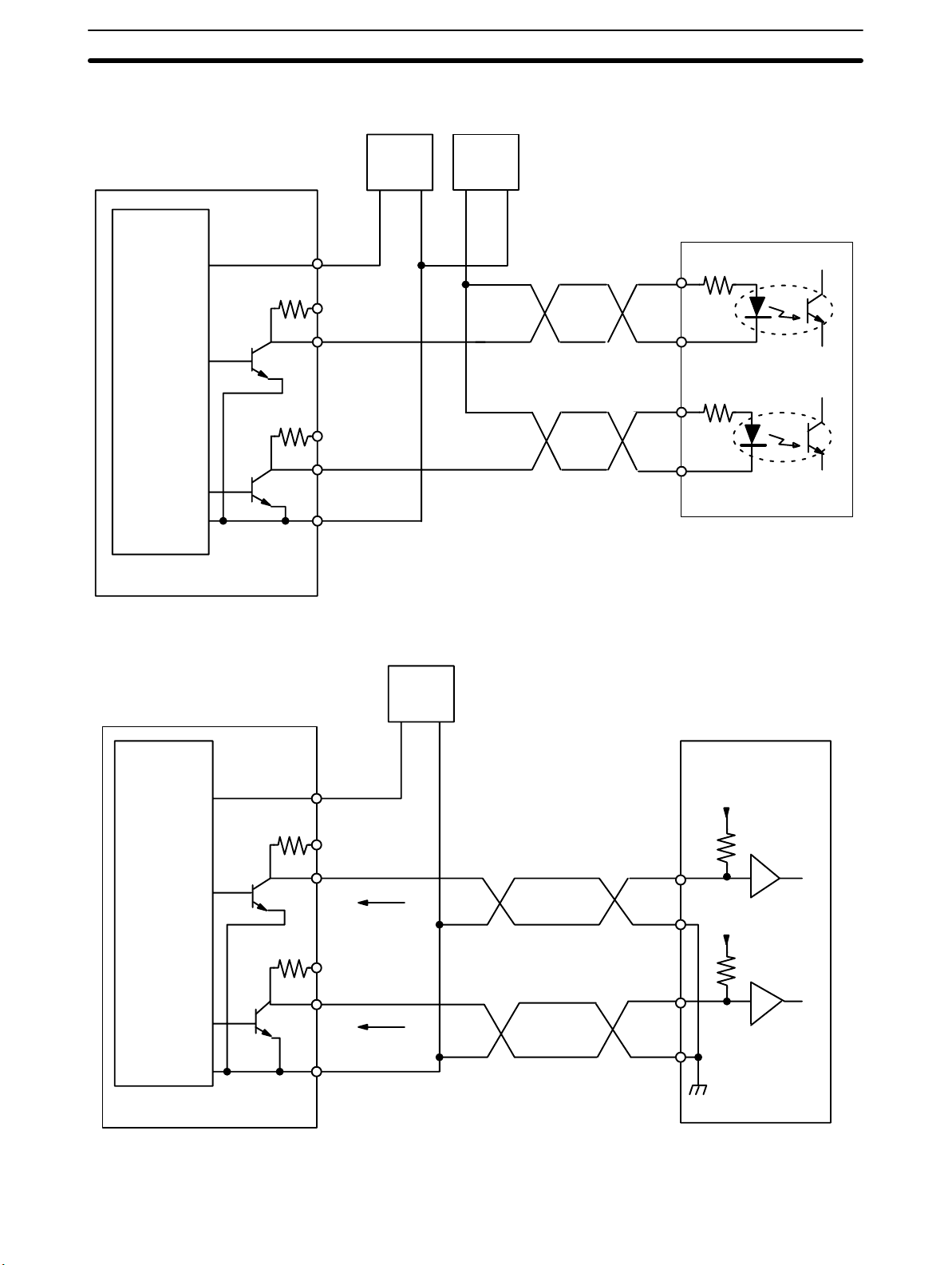
2-4SectionConnecting External I/O
Outputting CW and CCW
Pulses
Position Control Unit
24-VDC
input
CW pulse
output
CCW pulse
output
1.6 kΩ
1.6 kΩ
In this example, a 5-VDC photocoupler input motor driver is used for outputting
CW and CCW pulses.
24-VDC
power
supply
+–
A1/B1
A5/B5
A7/B7
A2/B2
5-VDC
power
supply
+–
Motor driver (for 5-VDC input)
+
–
+
–
Outputting Pulse and
Direction Signals
Position Control Unit
24-VDC
input
Pulse
(CW+CCW)
output
Direction
output
1.6 kΩ
1.6 kΩ
In this example, a 5-VDC input motor is used for outputting pulse and direction
signals.
24-VDC
power
supply
Motor driver (for 5-VDC input)
Direction input
Pulse input
A1/B1
A5/B5
A7/B7
A2/B2
+
7 to 30 mA
7 to 30 mA
–
32
When voltage-level output is used, the level is L for output ON, and H for output
OFF.
Page 46

2-4SectionConnecting External I/O
Error Counter Reset
Output
Position Control Unit
24-VDC
power
supply for
output
Position Control Unit
24-VDC
power
supply for
output
1.6 kΩ
There is approximately 20 ms of output when origin search is completed in
modes 1 or 2.
24-VDC
A1/B1
A10/B10
A2/B2
A1/B1
A10/B10
A2/B2
+
power
supply
–
5-VDC
power
supply
+–
24-VDC
power
supply
+–
+ECRST
–ECRST
+ECRST
–ECRST
OMRON R88D-UP
Servomotor Driver
5
6
OMRON R88D-UP
Servomotor Driver
5
6
2-4-2 Input Connection Examples
Caution If the switching capacity is too low it may cause damage to the switch. Connect a
!
switch with a switching capacity of at least 5 mA for each input.
With N.C. inputs, be sure to connect a power supply for unused terminals and
turn them on.
This section shows examples of connecting interrupt, emergency stop, and CW/
CCW limit input signals.
33
Page 47

The input section has both N.O. and N.C. inputs. Either can be used depending
on the axis parameter settings. For details regarding axis parameters, refer to
4-3 Axis Parameters Area.
External interrupt input signal N.O.
Emergency stop input signal N.C.
Origin proximity input signal N.C. or N.O.
CW limit input signal N.C. or N.O.
CCW limit input signal N.C. or N.O.
C200HW-NC113/213/413 Position Control Unit
2-4SectionConnecting External I/O
Name Connection type
24-VDC
power
supply
External
interrupt
input signal
Emergency
stop input
signal
Origin
proximity
input signal
CW limit
input signal
CCW limit
input signal
680 Ω
680 Ω
680 Ω
680 Ω
680 Ω
4.7 kΩ (1/2W)
Switch (N.O. contact)
4.7 kΩ (1/2W)
Switch (N.C. contact)
4.7 kΩ (1/2W)
Switch
(N.O./N.C. contact)
4.7 kΩ (1/2W)
Switch
(N.O./N.C. contact)
4.7 kΩ (1/2W)
Switch
(N.O./N.C. contact)
34
Page 48

2-4-3 Connecting Origin and Positioning Completed Input Signals
The examples below show input connections when open collector sensor output
and the encoder’s Z-phase line driver output are used.
Origin Input Signal (24 V)
2-4SectionConnecting External I/O
Position Control Unit
150 Ω
4.7 kΩ
680 Ω
A15/B15
A14/B14
Origin Input Signal (5 V) (Line Driver Input)
Position Control Unit
4.7 kΩ
150 Ω
680 Ω
A16/B16
A14/B14
24-VDC power
supply
+ –
Example:
OMRON E2R-A01 Proximity
Sensor (NPN output type)
+v
Signal
Switch
circuitry
0 V
OMRON R88D-UP
Servomotor Driver
24
+z
25
–z
Positioning Completed
Input Signal
Position Control Unit
The positioning completed input signal is also used as an origin search completed signal in modes 2 and 3. Adjust the setting of the servomotor driver so that
this signal always turns off while the servomotor is operating, and on when the
motor is stopped.
An origin search operation cannot be completed unless the positioning completed input signal turns ON after positioning has been completed.
24-VDC
power supply
OMRON R88D-UP
Servomotor Driver
8
INP
10
OGND
680 Ω
4.7 kΩ
(1/2W)
A1/B1
A12/B12
+
–
35
Page 49

2-4-4 Wiring Precautions
Operational errors such as dislocation can occur in most electronic control
devices if they are subjected to electronic noise from nearby power lines or
loads. Recovery from such errors is usually very difficult and time consuming. To
avoid such noise-generated operational errors and improve system reliability,
always observe the following precautions in wiring the system.
Be sure to use the sizes and materials indicated in the specifications when connecting power lines and cables.
Power lines (e.g., AC power supply, motor power line) and control lines (e.g.,
pulse output lines, external I/O signal lines) must be wired separately. Never put
these lines into the same duct or make them into a single bundle.
• Attach a 1-µF multi-layer ceramic capacitor to the pulse output power supply to
improve noise resistance.
• Use shielded cable for control lines.
• Connect the shielded cable to the frame ground at both the Position Control
Unit and the driver.
• Attach a surge absorber to all inductive loads, such as relays, solenoids, and
solenoid valves.
2-4SectionConnecting External I/O
DC relays AC relays
+
DC
–
Solenoids, etc.
Solenoid Surge absorber
Diode for surge
absorption
AC Surge
RYRY
absorber
Note Connect the diode and surge absorber as close as possible to the relay. Use a
diode capable of withstanding a voltage five times higher than the circuit voltage.
36
• Insert a noise filter into the power supply inlet if noise enters the power line
(e.g., when it is connected to the same power supply as an electric welder or an
electric spark machine or when there is any supply generating high frequency
noise).
• Use No. 3 or greater grounding contacts and the thickest possible wire, greater
2
than 1.25 mm
.
• Twisted-pair cable is recommended for power lines.
Page 50

2-5 Connections in Each Operating Mode
This section provides examples of wiring the X and Y axes. If the Y and U axes
are also to be used, check the connector pin numbers in 2-3 External I/O Cir-
cuitry and wire them in the same way.
Note 1. Be sure to connect a power supply for unused N.C. input terminals and turn
them on.
2. Use shielded wire for connecting to stepping motor drivers and servomotor
drivers. Connect the shielded cable to an FG at both the Position Control
Unit and the driver.
Example 1: Mode 0 Connection
This example shows the use of a stepping motor with an external sensor signal
connected to the origin input signal.
2-5SectionConnections in Each Operating Mode
Position Control Unit
CW output
(with 1.6 kΩ
resistance)
CCW output
(with 1.6 kΩ
resistance)
24-V power supply
for output
24-V GND
for output
Origin proximity input signal
Origin Input
signal
Input common
CCW limit
input signal
CW limit input
signal
Emergency
stop input
signal
A6
A8
A1
A2
A21
A15
A14
A24
A23
A22
A20
FG
+
24 VDC
24 VDC
+
Shield
N.O. contact
Signal
24 V/0 V
N.C. contact
Example:
DFU1507 stepping motor driver, made by Oriental Motor Co.
+CW
–CW
+CCW
–CCW
FG
N.C. contact
N.C. contact
PK543-NAC stepping motor
OMRON E2R-A01
Proximity Sensor
(NPN-output model).
37
Page 51
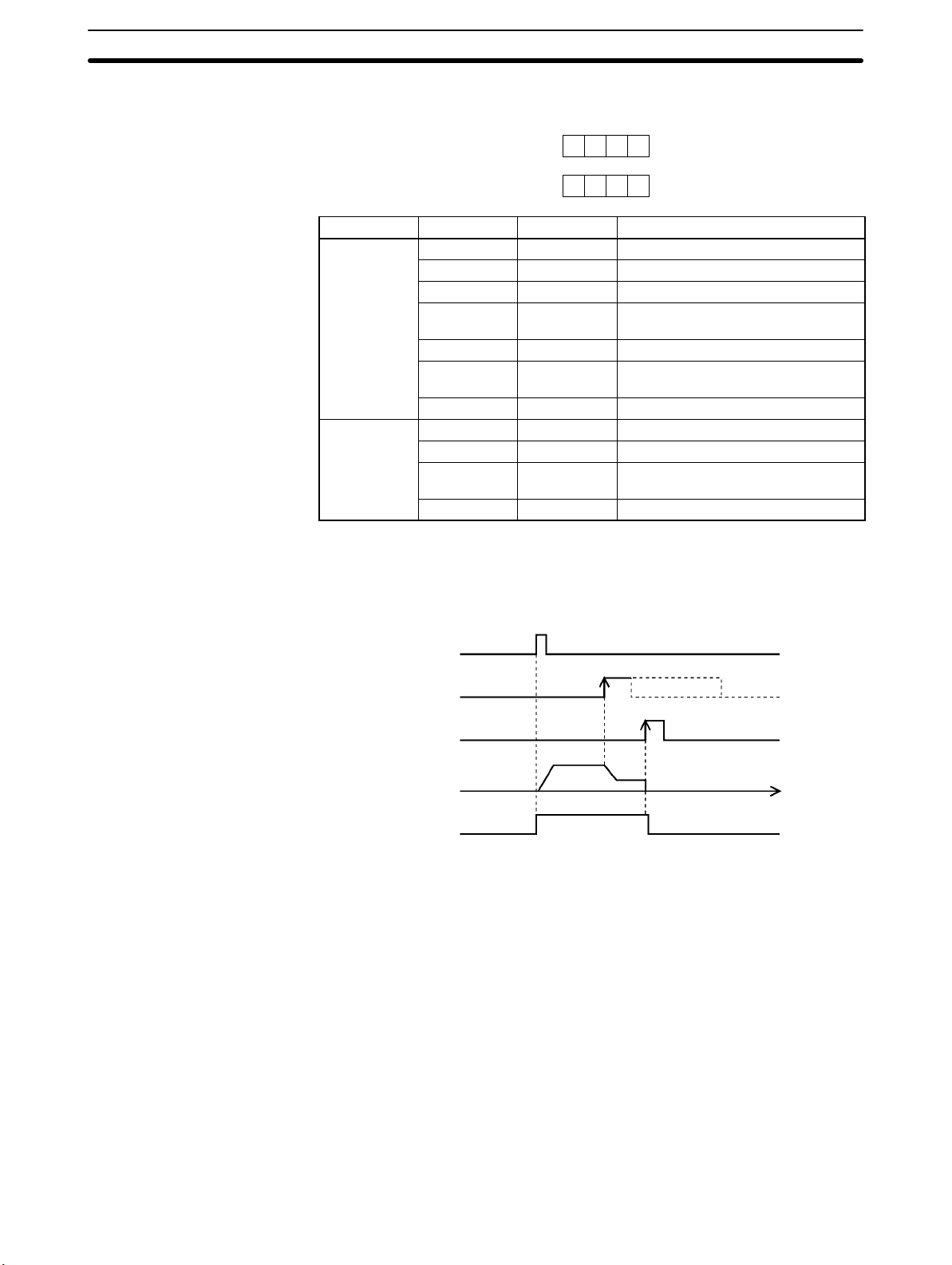
Parameter Setting Example
15 0
0 0 6 0
m+4
0 1 0 0
m+5
Word Bits Setting Contents
m+4
m+5
00 0 CW/CCW output
01 to 03 0 --04 0 Limit input: N.C. contact
05 1 Origin proximity input signal: N.O.
contact
06 1 Origin input signal: N.O. contact
07 0 Pulse output stopped with
emergency stop input signal.
08 to 15 0 --00 to 03 0 Mode 0
04 to 07 0 Reverse mode 1
08 to 11 1 Takes origin input signal after origin
proximity input signal is received.
12 to 15 0 Search direction: CW
2-5SectionConnections in Each Operating Mode
Note “m” is the beginning DM word allocated when the unit number is set.
Origin Search Operation
The origin search operation is completed with the rising edge of the origin input
signal after the rising edge of the origin proximity input signal.
ORIGIN
SEARCH
Origin proximity
input signal
Origin input
signal
Pulse output
Busy Flag
Time
38
Page 52

Example 2: Mode 1 Connection
In this example, a servomotor driver is employed and the Z-phase of the encoder
is connected to the origin line driver input terminal and used as the origin input
signal. An OMRON U-Series Servomotor Driver is used.
2-5SectionConnections in Each Operating Mode
Position Control Unit
CW output
(with 1.6 kΩ
resistance)
CCW output
(with 1.6 kΩ
resistance)
24-V power supply
for output
24-V GND for
output
Error counter reset
output
Origin input
signal
Input common
A6
A8
A1
A2
A11
A16
A14
A24
+
FG
24 VDC
Shield
24 VDC
+
N.C. contact
OMRON R88D-UPjjjj
Servomotor Driver
1
+CW
–CW
2
+CCW
3
–CCW
4
13 +24VIN
14 RUN
+ECRST
5
–ECRST
6
+Z
24
–Z
25
36 FG
R88M-U
Servomotor
Origin proximity
input signal
CCW limit
input signal
CW limit input
signal
Emergency stop
input signal
A21
N.O. contact
A23
N.C. contact
A22
N.C. contact
A20
N.C. contact
39
Page 53

2-5SectionConnections in Each Operating Mode
Parameter Setting Example
This example is explained in terms of the X axis. For more details, refer to 4-3
Axis Parameters Area.
15 0
0 0 E 0
m+4
0 0 0 1
m+5
Word Bits Setting Contents
m+4
m+5
00 0 CW/CCW output
01 to 03 0 --04 0 Limit input: N.C. contact
05 1 Origin proximity: N.O. contact
06 1 Origin input signal: N.O. contact
07 1 Pulse output stopped by emergency
stop input signal; error counter reset
signal output.
08 to 15 0 ---
00 to 03 1 Mode 1
04 to 07 0 Reverse mode 1
08 to 11 0 Takes origin input signal after rising
and falling edge of origin proximity
signal.
12 to 15 0 Motor direction: CW
Note “m” is the beginning DM word allocated when the unit number is set.
Origin Search Operation
The origin search operation stops on the rising edge of the first Z-phase signal
after the origin proximity signal has turned from ON to OFF, and after deceleration has ended.
ORIGIN SEARCH
Origin proximity
signal
Z-phase signal
Pulse output
Error counter
reset output
Approx. 20ms
Busy Flag
Time
40
Page 54

Example 3: Mode 2 Connection
In this example, as in example 2, a servomotor driver is employed and the
Z-phase of the encoder is connected to the origin line driver input terminal and
used as the origin input signal. An OMRON U-Series Servomotor Driver is used.
In contrast to mode 1, the positioning completed signal (INP) of the servomotor
driver serves as both the origin search completed and the positioning completed
signals.
Set the servomotor driver so that the positioning completed signal turns OFF
during motor operation and ON while the motor is stopped.
An origin search operation cannot be completed if the positioning completed
input signal from the servomotor driver is not properly connected or set.
Note If the positioning monitor time is set to 0, the origin search operation will wait until
the positioning completed signal turns ON but other operations, such as jogging
and memory operation, will ignore the positioning completed signal.
2-5SectionConnections in Each Operating Mode
Position Control Unit
CW output
(with 1.6 kΩ
resistance)
CCW output
(with 1.6 kΩ
resistance)
24-V power
supply for
output
24-V GND
for output
Error counter
reset output
Origin input
signal
Positioning
completed
input signal
Input
common
Origin
proximity
input signal
CCW limit
input signal
CW limit
input signal
Emergency
stop input
signal
A6
A8
A1
A2
A11
A16
A14
A12
A24
A21
A23
A22
A20
24
VDC
FG
24 VDC
+
N.O. contact
N.C. contact
N.C. contact
N.C. contact
Shield
N.C. contact
OMRON R88D-UPjjjj
Servomotor Driver
R88M-U
1
2
3
4
13
14
5
6
24
25
8
10
36
+CW
–CW
+CCW
–CCW
+24
VIN
RUN
+ECRST
–ECRST
+Z
–Z
INP
GND
O
FG
Servomotor
41
Page 55
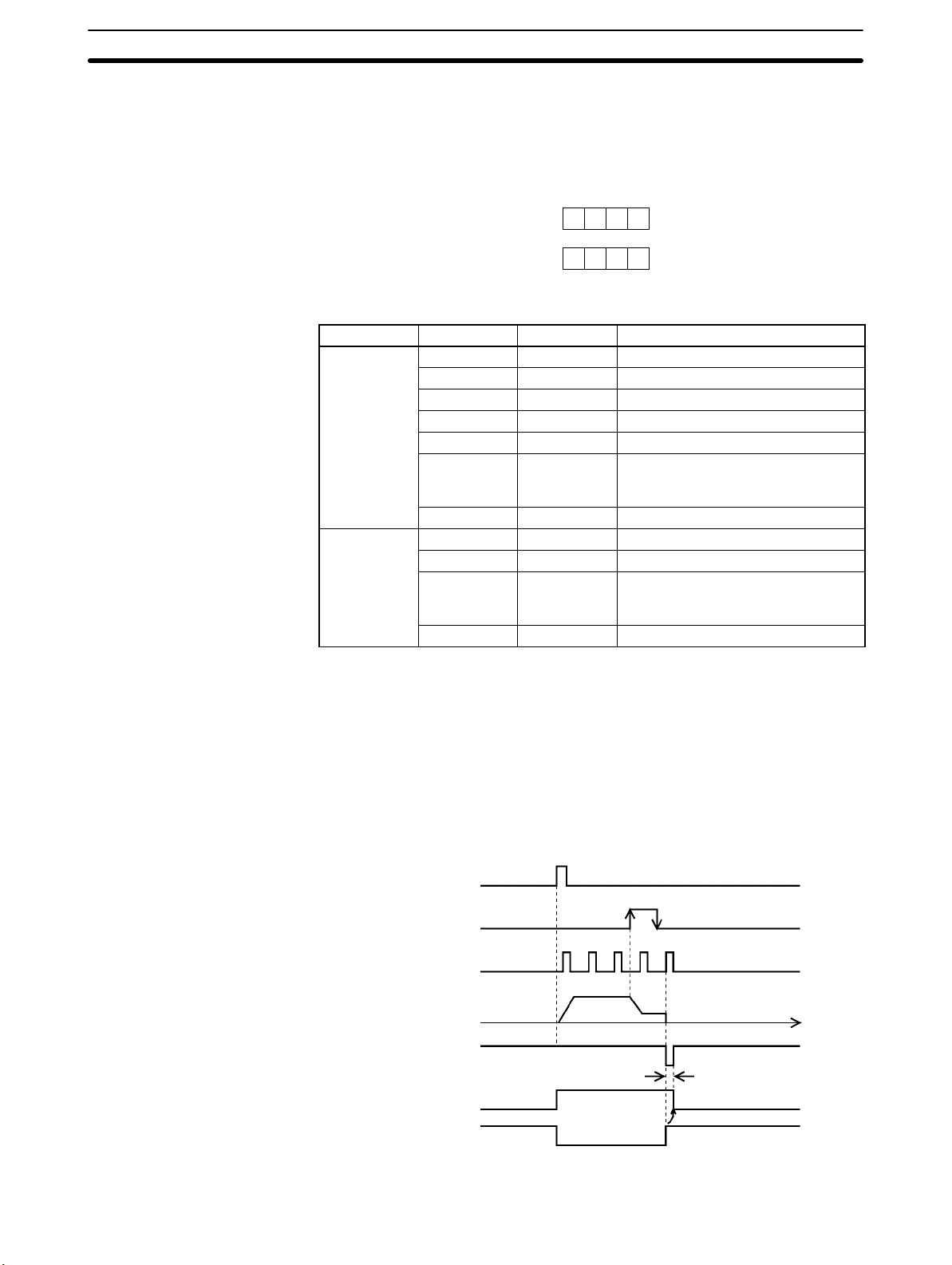
2-5SectionConnections in Each Operating Mode
Parameter Setting Example
This example is explained in terms of the X axis. For more details, refer to 4-3
Axis Parameters Area.
15 0
0 0 E 0
m+4
0 0 0 2
m+5
Word Bits Setting Contents
m+4
m+5
00 0 CW/CCW output
01 to 03 0 --04 0 Limit input: N.C. contact
05 1 Origin proximity: N.O. contact
06 1 Origin input signal: N.O. contact
07 1 Pulse output stopped by emergency
stop input signal; error counter reset
signal output.
08 to 15 0 --00 to 03 2 Mode 2
04 to 07 0 Reverse mode 1
08 to 11 0 Takes origin input signal after rising
and falling edge of origin proximity
input signal.
12 to 15 0 Search direction: CW
Note “m” is the beginning DM word allocated when the unit number is set.
Origin Search Operation
The origin search operation stops on the rising edge of the first Z-phase signal
after the origin proximity signal has turned from ON to OFF, and after deceleration has ended. The Busy Flag turns OFF with the positioning completed signal.
ORIGIN
SEARCH
Origin proximity
signal
Z phase signal
Pulse output
Error counter
reset output
Busy Flag
Positioning completed
input signal
Approx. 20ms
Time
42
Page 56

Example 4: Mode 3 Connection
This is an example using the origin adjustment function of OMRON’s Servomotor Driver. The positioning completed signal (INP) is used as both the origin
search completion and the positioning completed signal.
Be sure to adjust the settings of the servomotor driver so that the positioning
completed signal is OFF when the motor is operating and ON when it is stopped.
Note If the positioning monitor time is set to 0, the origin search operation will wait until
the positioning completed signal turns ON but other operations, such as jogging
and memory operation, will ignore the positioning completed signal.
2-5SectionConnections in Each Operating Mode
Position Control Unit
CW output
(with 1.6 kΩ
resistance)
CCW output
(with 1.6 kΩ
resistance)
24-V power
supply for
output
24-V GND
for output
Origin
adjustment
command
output
Positioning
completed
input signal
Input
common
Origin
proximity
input signal
CCW limit
input signal
A6
A8
A1
A2
A10
A12
A24
A21
A23
24 VDC
FG
+
N.O. contact
N.C. contact
Shield
24 VDC
N.C. contact
N.C. contact
OMRON R88D-UPjjjj
Servomotor Driver
R88M-U
15
34
14
33
19
18
36
13
6
11
28
37
26
+CW
–CW
+CCW
–CCW
+24 VIN
+5 VOUT
+5 VIN
RUN
EM
HRET
INP
24 VG
FG
Servomotor
CW limit
input signal
Emergency
stop input
signal
A22
N.C. contact
A20
N.C. contact
43
Page 57

2-5SectionConnections in Each Operating Mode
Parameter Setting Example
This example is explained in terms of the X axis. For more details, refer to 4-3
Axis Parameters Area.
15 0
0 0 6 0
m+4
0 0 0 3
m+5
Word Bits Setting Contents
m+4
m+5
00 0 CW/CCW output
01 to 03 0 --04 0 Limit input: N.C. contact
05 1 Origin proximity: N.O. contact
06 1 Origin input signal: N.O. contact
07 0 Pulse output stopped by emergency
stop input.
08 to 15 0 --00 to 03 3 Mode 3
04 to 07 0 Reverse mode 1
08 to 11 0 Takes origin input signal after rising
and falling edge of origin proximity
signal.
12 to 15 0 Search direction: CW
Note “m” is the beginning DM word allocated when the unit number is set.
Origin Search Operation
The origin search operation begins after the origin proximity signal has risen and
fallen, and the origin adjustment command is output to the servomotor driver
after deceleration has ended. The positioning completed signal is then input
from the servomotor driver and origin search ends. The driver internally
executes the error counter reset and stops automatically with the first Z-phase
input after it has received the origin adjustment command.
ORIGIN
SEARCH
Origin proximity
signal
Pulse output
Origin adjustment
command output
Positioning completed input signal
Busy Flag
Time
44
Page 58

2-6 Connection of Unused Axes
This section provides a connection example for the C200HW-NC213/NC413 in
applications where not all axes are used.
2-6-1 C200HW-NC213 – X Axis Only
Based on Example 2: Mode 1 Connection on page 39, the following example
shows the external I/O connections for the C200HW-NC213 when only the X
axis (and not the Y axis) is used. In this example, the limit input signals for both
axes are set to N.C. contacts. With the C200HW-NC413, if the Z axis is used and
the U axis is not used, the connection will be the same with X and Y replaced by Z
and U respectively.
Position Control Unit
2-7SectionServo Relay Unit
Input
common
Origin
proximity
input
signal
CCW limit
input signal
CW limit
input signal
Emergency
stop input
signal
X axis (used)
Y axis
(not used; no wiring required)
X axis (used)
Y axis (not used)
X axis (used)
Y axis (not used)
X axis (used)
Y axis (not used)
24 VDC
N.O. contact
N.C. contact
N.C. contact
N.C. contact
When there is an unused axis, connect the emergency stop input signal (N.C.
contact) and the CW/CCW limit input signals (N.C./N.O. switchable) for that axis
so that they are ON. If the parameters are at their default settings, the CW/CCW
limit input signals are N.C. contact inputs and so connect an input power supply
and keep power ON.
If the emergency stop input signal and the CW/CCW limit input signals for an
unused axis are not ON, a sensor input error (error codes 6000, 6100, or 6101)
will be generated for the axis, and the ERR and SENS indicators as well as the
LED indicator for the axis will light or flash. The used axis, however, will continue
to operate normally even if an error is generated for the unused axis.
Note If the CW/CCW limit input signals for the unused axis are set to N.O contacts
using the parameter settings, it is not necessary to wire the CW/CCW limit
inputs. For details, refer to 4-3 Axis Parameters and 4-8 Setting Data for Unused
Axes.
2-7 Servo Relay Unit
• Wiring requirements can be reduced by connecting Servo Drivers and PCUs
via a Servo Relay Unit, which provide a connector and a terminal block in one
Unit.
45
Page 59

Connections Diagram
jjj
jjj
jjj
jjj
jjj
jjj
jjj
jjj
XW2Z-jjjJ-Aj
Connecting Cable
• The connecting cable and the type of Servo Relay Unit required will depend on
the Servo Driver model connected. Refer to the tables under Connection Com-
patibility given below.
Position Control Unit
C200HW-NC113
C200HW-NC213
C200HW-NC413
XW2Z-jjjJ-Bj
Connecting Cable
XW2B-jjJ6-j
Servo Relay Unit
Servo Driver
R88D-UPjjj
R88D-MTjj
R88D-Hjjj
R88D-UTjjj
R88D-UEPjjj
R88D-WTjjjj
R7D-APjjj
2-7SectionServo Relay Unit
Connection Compatibility
PCU Cable connected to
PCU
C200HW-NC113
C200HW-NC213
C200HW-NC413
XW2Z-jjjJ-A6
XW2Z-jjjJ-A8
XW2Z-jjjJ-A7
XW2Z-jjjJ-A9
Servo Relay Unit Cable connected to
Servo Relay Unit
XW2B-20J6-1B
(for C200H-NC112)
XW2B-20J6-1B
XW2B-40J6-2B
(for C200H-NC211)
XW2B-40J6-2B
XW2Z-jjjJ-B1 R88D-UPjjj
XW2Z-jjjJ-B2 R88D-MTjjj
XW2Z-jjjJ-B3 R88D-Hjjj
XW2Z-jjjJ-B4
XW2Z-jjjJ-B5
XW2Z-jjjJ-B1 R88D-UPjjj
XW2Z-jjjJ-B2 R88D-MTjjj
XW2Z-jjjJ-B3 R88D-Hjjj
XW2Z-jjjJ-B4
XW2Z-jjjJ-B5
Servo Driver
R88D-UTjjj
R88D-WTjjjj
R88D-UEPjjj
R7D-APjjj
R88D-UTjjj
R88D-WTjjjj
R88D-UEPjjj
R7D-APjjj
• The cable length for PCU Connecting Cables is indicated in the “jjj”.
050: 0.5 m
100: 1 m
• The cable length for Servo Driver Connecting Cables is indicated in the
“jjj”.
100: 1 m
200: 2 m
• When using the C200HW-NC413, 2 Servo Relay Units and 2 PCU Connecting
Cables are required.
• When using in combination with the C200HW-NC213 (2-axis control), 2 Servo
Driver Connecting Cables are required.
• When using in combination with the C200HW-NC413 (4-axis control), 4 Servo
Driver Connecting Cables are required.
46
Page 60

SECTION 3
Getting Started
This section is directed to first-time users of the Position Control Unit (PCU). It explains how to use the RELATIVE MOVEMENT command employing the direct operation method, and provides examples of how to use a stepping motor. In order to
keep the explanations simple, the minimum system required for operating the motor is used, and operations from the Programming Console are described.
In general, using a PCU requires the creation of ladder programs incorporating various kinds of data, status information,
external input information, and so on, but here the explanations are aimed only at how to operate the motor. For details regarding data configuration and allocation, refer to Section 4 Data Areas.
3-1 Basic Operations 48. . . . . . . . . . . . . . . . . . . . . . . . . . . . . . . . . . . . . . . . . . . . . . . . . . . . . . . . .
3-2 System Configuration and Wiring 49. . . . . . . . . . . . . . . . . . . . . . . . . . . . . . . . . . . . . . . . . . . .
3-3 Setting Data and Starting 51. . . . . . . . . . . . . . . . . . . . . . . . . . . . . . . . . . . . . . . . . . . . . . . . . . .
47
Page 61

3-1 Basic Operations
3-1SectionBasic Operations
Outline
The examples provided in this section show how to operate a stepping motor
using the direct operation method. It is assumed that a C200HX/HG/HE CPU
Unit and a C200HW-NC113 PCU are employed, and the PCU’s factory settings
are used for the parameters.
Pulse output
1,000 pps
Target
position:
5,000 pulses
0.2 ms 0.2 ms
Target speed: 1,000 pps
Time
The stepping motor rotates for approximately five seconds in the clockwise
(CW) direction (i.e., in the direction that increments the present position), and
then stops.
Use the Programming Console for the required settings and the START command. First set the data required for direct operation and then operate the motor
by turning the RELATIVE MOVEMENT command bit from OFF to ON.
The set values for acceleration and deceleration times and the actual acceleration and deceleration times are related to the axis parameters area’s maximum
speed and actual target speed set values. For details, refer to Appendix B Esti-
mating Times and Pulses for Acceleration/Deceleration.
Programming Console
Data settings
RELATIVE
MOVEMENT
command bit ON
PC PCU
RELATIVE
MOVEMENT
command
Pulse output
Stepping motor driver
Stepping motor rotation
The following data must be set for this example.
• Position: 5,000 pulses
• Speed: 1,000 pps
• Acceleration time: 100 ms (factory setting)
• Deceleration time: 100 ms (factory setting)
Set the position and speed in the operating data area which is set by the common parameter area. For the acceleration and deceleration times, use the factory settings saved to the PCU.
For more details regarding the common parameter area and the operating data
area, refer to Section 4 Data Areas.
Operating Procedure
48
Use the following procedure to operate the motor.
1, 2, 3... 1. Mount all of the Units and connect the Programming Console. (Refer to 3-2
System Configuration and Wiring and also refer to the C200HX/HG/HE PCs
Installation Guide.)
Page 62
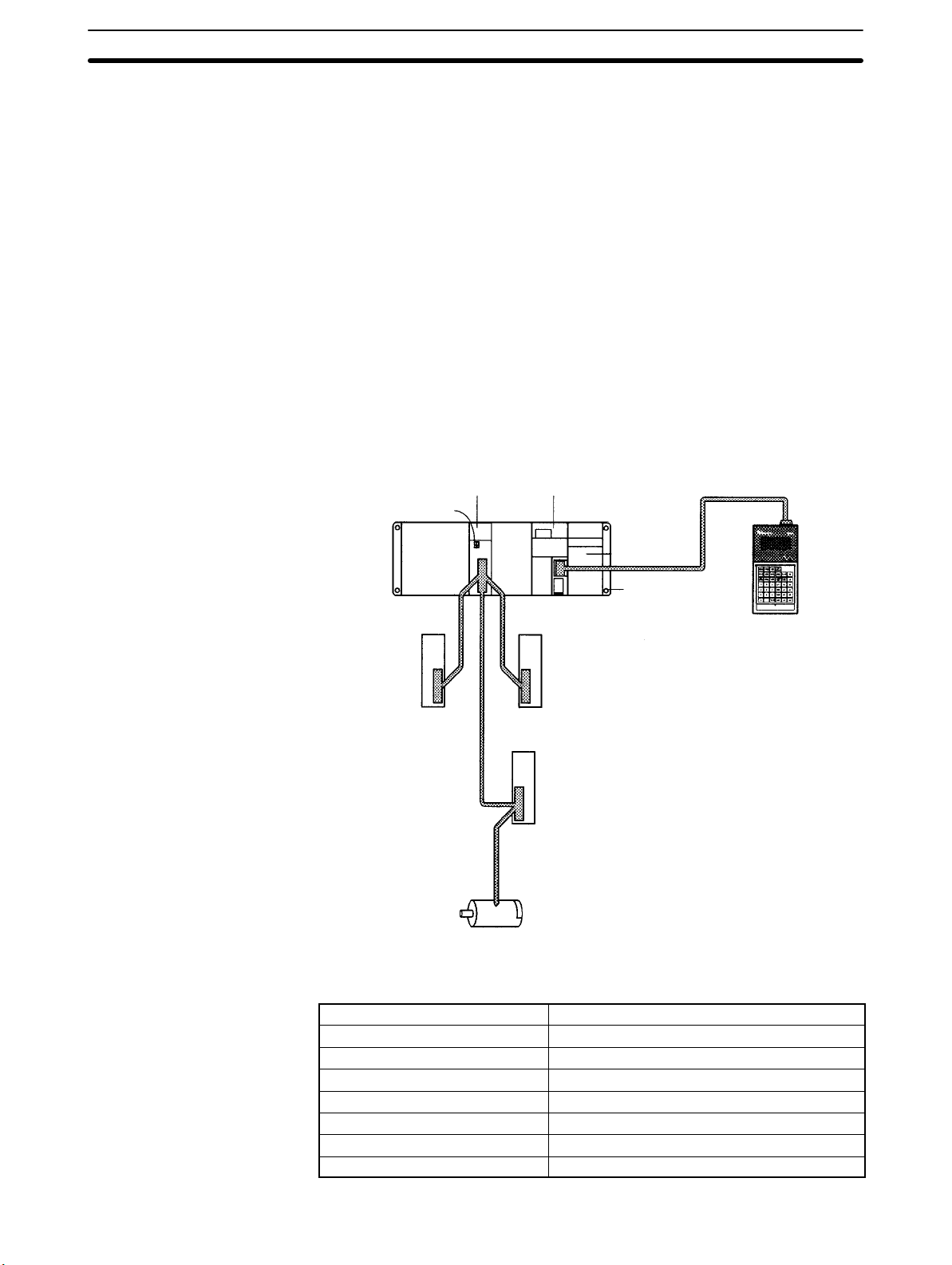
2. Set the unit number for the PCU. (Refer to 3-2 System Configuration and
Wiring.)
3. Wire the PCU’s external inputs and wire the PCU to the stepping motor.
(Refer to 3-2 System Configuration and Wiring.)
4. Turn on the power supply and set the common parameter area. (Refer to 3-3
Setting Data and Starting.)
5. Turn on the power again or restart. (Refer to 3-3 Setting Data and Starting.)
6. Set the position, the speed, the acceleration time number, and the deceleration time number. (Refer to 3-3 Setting Data and Starting.)
7. Start. (Refer to 3-3 Setting Data and Starting.)
3-2 System Configuration and Wiring
3-2SectionSystem Configuration and Wiring
(1) System Configuration
For this operation, use the configuration shown in the following diagram. In this
example only the motor will rotated, without using the mechanical system.
For the purposes of this example, it is assumed that the CPU is mounted to the
CPU Backplane and that the unit number is set to #0.
Position Control Unit CPU Unit
Set to Unit #0.
24-VDC power
supply
Power Supply
Unit
CPU Backplane
24-VDC power
supply
Stepping motor driver
Connecting cable
Programming Console
Stepping motor
The following Units and devices are used in this example.
CPU Unit SYSMAC C200HX/HG/HE
Position Control Unit C200HW-NC113
Power Supply Unit C200HW-PA204
CPU Backplane C200HW-BC101
Programming Console C200H-PRO27-E
Connecting cable C200H-CN222
Stepping motor driver DFU1507 (Oriental Motor Co.)
Stepping motor PK543-NAC (Oriental Motor Co.)
49
Page 63

3-2SectionSystem Configuration and Wiring
(2) Rotary Switch Setting
(3) Wiring
Position Control Unit
CW pulse output
(with 1.6 kΩ
resistance)
Use the rotary switch on the front panel of the PCU to set the unit number (i.e.,
the machine No.).
MACHINE No. 0
For details regarding rotary switch settings, refer to 2-2 Components.
Wire the system as shown in the following diagram. The CW limit input, CCW
limit input, and emergency stop input are factory set as N.C. terminals, so shortcircuit them.
Stepping motor driver
Stepping motor
PK543-NAC
(Oriental Motor Co.)
CCW pulse output
(with 1.6 kΩ
resistance)
24-V
power
supply
for
output
24-V
GND for
output
Input
common
CCW
limit
output
CW limit
output
Emergency
stop
input
signal
DFU1507
(Oriental Motor Co.)
24-VDC power supply
24-VDC power supply
50
For details on connecting the PCU and the stepping motor driver, refer to the
motor driver specifications and also Section 2 Specifications and Wiring.
Page 64

3-3 Setting Data and Starting
3-3SectionSetting Data and Starting
(4) Setting the Common
Parameters
(5) Powering-up Again or
Restarting
(6) Setting the Operating
Data Area
The designation of the operating data area and the mounting position of the PCU
are set in the common parameters. Use the Programming Console to write the
following data to DM 1000 through DM 1002. The common parameters area is
automatically specified when the PCU is set as Unit #0, and this data must be
set.
DM 1000
DM 1001
DM 1002
0 0 0 D
0 5 0 0
0 0 0 0
The Data Memory (DM) area is used as the operating
data area. Set the “D” for the DM area.
Set DM 0500 as the beginning word in the operating
data area.
Set the PCU’s mounting position as the CPU
Backplane or the Expansion I/O Backplane. Use the
parameters saved to the PCU.
After making the settings, either turn on the power again or restart (by turning
AR 0100 from OFF to ON and then back OFF again). This will put the data that
has been set in the common parameters into effect.
For details regarding the common parameters area settings, refer to 4-2 Com-
mon Parameters Area.
By a setting in the common parameter area, the beginning word of the operating
data area has been set as DM 0500. Thus the words for the various data items
are as follows:
• Position: DM 0507 and DM 0506
• Speed: DM 0508
• Acceleration/deceleration times: DM 0510
Setting Position Data (DM 0507: Leftmost; DM 0506: Rightmost)
Use the Programming Console to write the following data.
(7) Starting
DM 0506
DM 0507
5 0 0 0
0 0 0 0
Enter 5000 (pulses) in 4 digits BCD, divided into
leftmost and rightmost.
Setting Speed Data (DM 0508)
Use the Programming Console to write the following data.
DM 0508
1 0 0 0
Enter 1000 (pps) in 4 digits BCD.
Setting Acceleration/Deceleration Times (DM 0510)
Use the Programming Console to write the following data.
DM 0519
0 0 0 0
Set acceleration time #0 and deceleration time #0.
When “0” is set, the acceleration/deceleration times
specified in the parameters saved to the PCU are used.
Not used in this example. Set to “00.”
Acceleration time #0
Deceleration time #0
• For details regarding the operating data area, refer to 4-5 Operating Data
Area.
• In this example, the direct operation method is used. For details regarding
direct operation, refer to Section 7 Direct Operation.
Starting is executed by turning ON the RELATIVE MOVEMENT command bit in
the operating memory area (IR area).
The RELATIVE MOVEMENT command is allocated to bit 10004 in the IR area.
Use the Programming Console to turn this bit from OFF to ON.
51
Page 65

3-3SectionSetting Data and Starting
The operating memory area is the area that is automatically specified when the
PCU’s unit number is set (Unit #0).
04
Wd 100
RELATIVE MOVEMENT
Direct operation is started by the
RELATIVE MOVEMENT command
(i.e., by the turning ON of bit 10004).
• For details regarding the operating memory area, refer to 4-4 Operating
Memory Area.
• In this example, the direct operation method is used. For details regarding
direct operation, refer to Section 7 Direct Operation.
52
Page 66

This section provides information on the data areas used by the Position Control Unit.
4-1 Overall Structure 54. . . . . . . . . . . . . . . . . . . . . . . . . . . . . . . . . . . . . . . . . . . . . . . . . . . . . . . . .
4-1-1 Flash Memory 55. . . . . . . . . . . . . . . . . . . . . . . . . . . . . . . . . . . . . . . . . . . . . . . . . . . .
4-1-2 Waiting for PCU Startup 56. . . . . . . . . . . . . . . . . . . . . . . . . . . . . . . . . . . . . . . . . . . .
4-1-3 Area Allocation 56. . . . . . . . . . . . . . . . . . . . . . . . . . . . . . . . . . . . . . . . . . . . . . . . . . .
4-1-4 Data Areas 58. . . . . . . . . . . . . . . . . . . . . . . . . . . . . . . . . . . . . . . . . . . . . . . . . . . . . . .
4-2 Common Parameters 74. . . . . . . . . . . . . . . . . . . . . . . . . . . . . . . . . . . . . . . . . . . . . . . . . . . . . .
4-3 Axis Parameters 76. . . . . . . . . . . . . . . . . . . . . . . . . . . . . . . . . . . . . . . . . . . . . . . . . . . . . . . . . .
4-3-1 Setting the Axis Parameters 76. . . . . . . . . . . . . . . . . . . . . . . . . . . . . . . . . . . . . . . . . .
4-3-2 Axis Parameters Details 77. . . . . . . . . . . . . . . . . . . . . . . . . . . . . . . . . . . . . . . . . . . . .
4-3-3 Operation Modes 82. . . . . . . . . . . . . . . . . . . . . . . . . . . . . . . . . . . . . . . . . . . . . . . . . .
4-4 Operating Memory Area 83. . . . . . . . . . . . . . . . . . . . . . . . . . . . . . . . . . . . . . . . . . . . . . . . . . .
4-5 Operating Data Area 89. . . . . . . . . . . . . . . . . . . . . . . . . . . . . . . . . . . . . . . . . . . . . . . . . . . . . . .
4-6 Positioning Sequence Details 89. . . . . . . . . . . . . . . . . . . . . . . . . . . . . . . . . . . . . . . . . . . . . . . .
4-7 Setting Data With the SYSMAC-NCT Support Tool 93. . . . . . . . . . . . . . . . . . . . . . . . . . . . .
4-8 Setting Data for Unused Axes 93. . . . . . . . . . . . . . . . . . . . . . . . . . . . . . . . . . . . . . . . . . . . . . .
4-8-1 Settings Required for Unused Axes 93. . . . . . . . . . . . . . . . . . . . . . . . . . . . . . . . . . . .
SECTION 4
Data Areas
53
Page 67

4-1 Overall Structure
The Programmable Controller controls the Position Control Unit (PCU) by
means of the data and memory areas shown below, employing data inputs and
outputs during I/O refreshing and at other times.
For the purposes of this example, the explanation is provided in terms of a
C200HW-NC413 PCU. For details regarding area allocation for NC113 and
NC213 PCUs, refer to 4-1-3 Area Allocation.
IR area
Operating Memory Area
Operating
instructions
Status input
I/O refresh
PCU (NC413)
Instruction
interpretation
Status such as positioning completed,
present position
4-1SectionOverall Structure
Allocated
areas
Setting
areas
DM area
DM or EM
area
Parameter Area
Common
parameters
Axis
parameters
Operating Data Area
Transfer data
and other
operational data
Status input
Data Transfer Area
(See note 2.)
Memory
operation
data
Power up or restart
Power up or restart
(See note 1.)
I/O refresh
Data transfer
instruction execution
IOWR or IORD
execution
Data transfer
instruction execution
0004
0099
1000
1300
1400
1600
1620
1640
1660
4670
Save data
Common
parameters
Interpretation and
execution of set
data
Status such as I/O
signals of each axis,
error codes, etc.
Internal memory
Data areaAddress
Axis parameters
Positioning sequences
Speeds
Positions
Acceleration times
Deceleration times
Dwell times
Zones
Flash
memory
Data for the
X axis
Data for the
Y to U axes
Power up
or restart
54
Note 1. The user can select by means of a common parameters setting whether
data is to be transferred to the PCU for use, or whether the axis parameters
saved at the PCU are to be used. (Refer to 4-2 Common Parameters Area.)
2. The data transfer area is required for transferring data to the PCU (except
when the SYSMAC-NCT Support Tool is used).
Page 68

4-1SectionOverall Structure
The PCU uses the data and memory areas shown in the following table.
Name Contents Reference
Parameter
areas
Operating
memory
area
Operating
data area
Data
transfer
area
m: 1000+100 x Unit No.
n: 100+10 x Unit No. [Unit No.x9]
l: Beginning word address in DM or EM area, specified by the operating
k: Beginning word address in DM or EM area, specified by transfer source
Allocated to the PC’s DM Area when the PCU’s unit
number is set. The parameters for controlling the PCU
are set in the common parameter area, and the
parameters for controlling individual axes are set in the
axis parameters area.
Note The settings in the axis parameters area must be
made when the PCU is used. If these settings are
not made, a common parameters error will be generated (error codes 0010 to 0013) and the PCU will
not operate normally. Be sure to read 4-2 Common
Parameters.
Allocated to the Programmable Controller’s IR Area
when the PCU’s unit number is set. This area is used
for outputting data such as operational commands to
the PCU and for inputting the PCU status.
This area is set by the common parameters area. It is
used for inputting information related to the transfer of
memory operation data, direct operation settings such
as positions and speeds, and status data from the
PCU.
This area is set by the operating data area. When data
is transferred between the Programmable Controller
and the PCU, only that portion of the area employed
for transferring the data is used.
400+10 x (Unit No. – 10) [Unit No.yA(10)]
data area in the common parameter area.
word or transfer destination word in operating data area.
4-2
Common
Parameters
4-3 Axis
Parameters
4-4
Operating
Memory
Area
4-5
Operating
Data Area
---
4-1-1 Flash Memory
Note The data for the number of axes for the particular Position Control Unit being
The contents of the PCU’s internal memory are lost when the power supply is
turned off or when the PCU is restarted. By saving the contents of the internal
memory to the flash memory, parameters and other data can be retained.
• Axis parameters
• Positioning sequences
• Speeds
• Acceleration and deceleration times
• Dwell times
• Zones
used is all saved at once.
For details regarding saving data, refer to 5-7 Saving Data.
Parameters and other data that have been saved to flash memory are read to the
PCU’s internal memory when the PCU is powered up or restarted. If the parameters or other data are corrupted at that time, a parameter destruction error (error
code 0001) or data destruction error (error code 0002) will be generated and the
PCU will be started up using the initial values (i.e., the factory settings) or the
parameters and data that had been saved prior to the last save to flash memory.
If parameters or data are lost, no operation other than data transfer or data
saved can be received. After transferring the data, save the data and turn the
power off and then on again, or restart the PCU.
55
Page 69
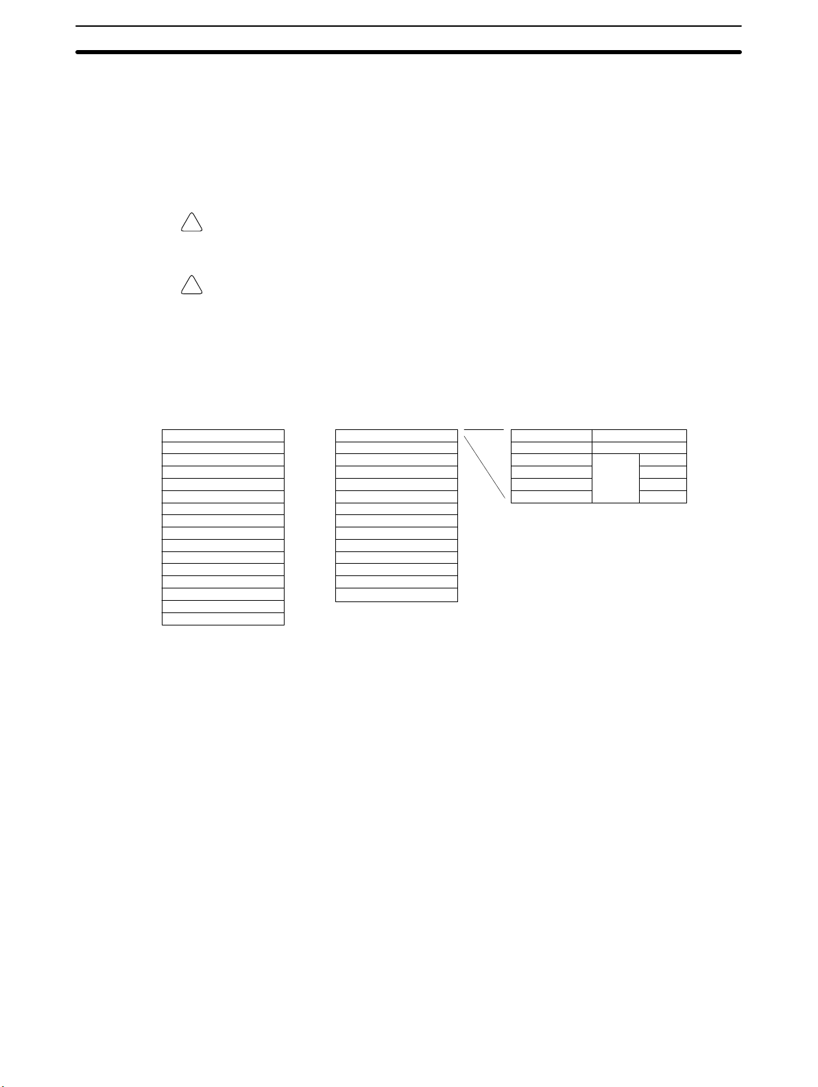
4-1-2 Waiting for PCU Startup
The Position Control Unit performs initial processing when it is powered up or
restarted. During this initial processing, the PCU cannot receive any instructions
or commands from the Programmable Controller and will ignore them. The
PCU’s X-axis Busy Flag remains ON until the initial processing is completed, so
after the PCU has been powered up or restarted, check to make sure that this
Busy Flag has turned OFF before executing a START.
Caution Carefully check to be sure that the parameters and data have been properly set
!
for correct operation.
Caution Before performing any operations that will change the Operating Memory Area,
!
check to be sure that the equipment will operate safely.
4-1-3 Area Allocation
4-1SectionOverall Structure
Parameter Areas
(Data Memory)
C200HW-NC113/NC213 C200HW-NC413
Unit #0
Unit #1
Unit #2
Unit #3
Unit #4
Unit #5
Unit #6
Unit #7
Unit #8
Unit #9
Unit #A
Unit #B
Unit #C
Unit #D
Unit #E
Unit #F
DM 1000 to DM 1099
DM 1100 to DM 1199
DM 1200 to DM 1299
DM 1300 to DM 1399
DM 1400 to DM 1499
DM 1500 to DM 1599
DM 1600 to DM 1699
DM 1700 to DM 1799
DM 1800 to DM 1899
DM 1900 to DM 1999
DM 2000 to DM 2099
DM 2100 to DM 2199
DM 2200 to DM 2299
DM 2300 to DM 2399
DM 2400 to DM 2499
DM 2500 to DM 2599
Each unit number occupies 100 words, allocated from DM 1000 to DM 2599 (or
DM 2499 for NC413 PCUs).
Unit #0
Unit #1
Unit #2
Unit #3
Unit #4
Unit #5
Unit #6
Unit #7
Unit #8
Unit #A
Unit #B
Unit #C
Unit #D
Unit #E
DM 1000 to DM 1099
DM 1100 to DM 1199
DM 1200 to DM 1299
DM 1300 to DM 1399
DM 1400 to DM 1499
DM 1500 to DM 1599
DM 1600 to DM 1699
DM 1700 to DM 1799
DM 1800 to DM 1899
DM 2000 to DM 2099
DM 2100 to DM 2199
DM 2200 to DM 2299
DM 2300 to DM 2399
DM 2400 to DM 2499
Word address Contents
m to m+3
m+4 to m+27
m+28 to m+51
m+52 to m+75
m+76 to m+99
m: 1000+100 x Unit No.
Common parameters
Axis
parameters
For X axis
For Y axis
For Z axis
For U axis
56
Page 70

4-1SectionOverall Structure
p
Operating Memory Area
(IR Area)
C200HW-NC113/NC213 C200HW-NC413
Unit #0
Unit #1
Unit #2
Unit #3
Unit #4
Unit #5
Unit #6
Unit #7
Unit #8
Unit #9
Unit #A
Unit #B
Unit #C
Unit #D
Unit #E
Unit #F
C200HW-NC413
Unit #0
Unit #1
Unit #2
Unit #3
Unit #4
Unit #5
Unit #6
Unit #7
Unit #8
Unit #A
Unit #B
Unit #C
Unit #D
Unit #E
IR 100 to IR 109
IR 110 to IR 119
IR 120 to IR 129
IR 130 to IR 139
IR 140 to IR 149
IR 150 to IR 159
IR 160 to IR 169
IR 170 to IR 179
IR 180 to IR 189
IR 190 to IR 199
IR 400 to IR 409
IR 410 to IR 419
IR 420 to IR 429
IR 430 to IR 439
IR 440 to IR 449
IR 450 to IR 459
IR 100 to IR 119
IR 110 to IR 129
IR 120 to IR 139
IR 130 to IR 149
IR 140 to IR 159
IR 150 to IR 169
IR 160 to IR 179
IR 170 to IR 189
IR 180 to IR 199
IR 400 to IR 419
IR 410 to IR 429
IR 420 to IR 439
IR 430 to IR 449
IR 440 to IR 459
C200HW-NC113/213 PCUs occupy 10 words in the IR Area for Special I/O
Units, and C200HW-NC413 PCUs occupy 20 words in that area.
C200HW-NC213
I/O
Word address Axis
Output
Input
C200HW-NC413
I/O
Output
Input
n to n+1
n+2 to n+4
Word address Axis
n to n+1
n+2 to n+3
n+4 to n+5
n+6 to n+7
n+8 to n+10
n+11 to n+13
n+14 to n+16
n+17 to n+19
X axis
X axis
n: 100+10 x Unit No. (Unit No. x9)
400+10 x (Unit No. - 10) (Unit No. yA(10))
X axis
Y axis
Z axis
U axis
X axis
Y axis
Z axis
U axis
I/O
Output
Input
Word address Axis
n to n+1
n+2 to n+3
n+4 to n+6
n+7 to n+9
X axis
Y axis
X axis
Y axis
Operating Memory Area
Note 1. The C200HW-NC413 occupies the space for two unit numbers, i.e., the unit
number that is set and also the following number. For example, if the unit
number is set to 0, then the area for unit numbers 0 and 1 is allocated.
2. Be sure to set the unit numbers so that they do not overlap with the unit numbers of other Special I/O Units.
3. Since the C200HW-NC413 occupies the space for two unit numbers, it cannot be set for unit numbers 9 or F.
Depending on the model of the Programmable Controller that is used, it may not
be possible to set PCU unit numbers from A to F (E). Please check the operation
manual of the Programmable Controller.
For details regarding operating memory area settings, refer to Parameter Areas
under 4-1-4 Data Areas and 4-2 Common Parameter Area.
Common Parameter Area
15 00
0
3
x10
x102x101x10
0 0 0
x: D (DM area), E (EM area)
0
Beginning word address
I
m
m+1
C200HW-NC113
I/O Word address Axis
Output
Input I+11 to I+12 X axis
I to I+5 Common
I+6 to I+10 X axis
57
Page 71

C200HW-NC213
p
p
p
p
I/O Word address Axis
Output
Input
C200HW-NC413
I/O Word address Axis
Output
Input
4-1SectionOverall Structure
I to I+5 Common
I+6 to I+10 X axis
I+11 to I+15 Y axis
I+16 to I+17 X axis
I+18 to I+19 Y axis
I to I+5 Common
I+6 to I+10 X axis
I+11 to I+15 Y axis
I+16 to I+20 Z axis
I+21 to I+25 U axis
I+26 to I+27 X axis
I+28 to I+29 Y axis
I+30 to I+31 Z axis
I+32 to I+33 U axis
Note “I” represents the beginning word address of the area designated by the com-
mon parameter area.
Example
When the common parameter area settings are made as shown in this example,
the operating data area will be allocated to DM 0100 onwards.
There is no EM area for C200H/HS/HE Programmable Controllers, so in that
case the EM area cannot be designated for the operating data area.
Data Transfer Area
For details regarding data transfer area settings, refer to Operating Data Area
under 4-1-4 Data Areas.
4-1-4 Data Areas
Parameter Area
Common Parameters (Data Memory)
Designation of Operating Data Area
Word m
Common Parameter Area
15 00
0
m
m+1
15 00
0
0 0 D
0
1 0 0
0 0 X
Designate the memory area to which the operating memory is to be set.
X = D (DM area)
E (EM area)
Beginning Word of Operating Data Area
Word m+1
15 00
3
x10
58
x10
2
x10
1
x10
0
Page 72

Designate the beginning word of the operating data area.
Unit Mounting Position and Parameter Designation
Word m+2
4-1SectionOverall Structure
Axis Parameters (Data Memory)
15 00
Mounting position
08 07
Parameter designation
Mounting Position
00: To be mounted on the CPU Rack or Expansion I/O Rack
01: To be mounted to a Remote Slave Rack
Parameter Designation
00: Operate according to the axis parameters saved to the PCU.
01: Operate according to the axis parameters in DM words m+4 to m+99.
Reserved
Word m+3
Set to 0000.
I/O Settings
X axis m+4 (NC113), Y axis m+28 (NC213), Z axis m+52 and U axis m+76
(NC413)
15 00
0000000 000I/O settings
Bit Item Settings
00 Output pulse selection 0: CW/CCW output; 1: Pulse/Direction output
01 to 03 Reserved Set to 0.
04 Limit input signal type 0: N.C input, 1: N.O input
05 Origin proximity input
signal type
06 Origin input signal type 0: N.C input, 1: N.O input
07 Emergency stop input 0: Stop only pulse output
08 Origin undefined
designation
09 to 15 Reserved Set to 0.
08 04
0: N.C input, 1: N.O input
1: Pulse output stop and error counter reset
output (enabled for operation modes 1
and 2)
0: Retain prior status (for emergency stop or
limit inputs)
1: Forcibly change to origin undefined status
59
Page 73

4-1SectionOverall Structure
Operation Mode Selection
X axis m+5 (NC113), Y axis m+29 (NC213), Z axis m+53 and U axis m+77
(NC413)
15 00
Origin search direction Origin detection method Origin search operation Operation mode
12 11 08 07 04 03
Bit Item Settings
00 to 03 Operation mode 0 (Mode 0): Uses stepping motor, and uses
external sensor signal as origin input signal.
1 (Mode 1): Uses servomotor driver, and
uses encoder’s Z-phase signal for origin
input signal. Does not use positioning
completed signal.
2 (Mode 2): Same as Mode 1, but uses
positioning completed signal.
3 (Mode 3): Uses OMRON H-Series or
M-Series Servomotor Driver. Origin search is
completed by Servomotor Driver’s origin
adjustment command. Uses positioning
completed signal.
04 to 07 Origin search operation 0: Reverse mode 1 (reverse at limit input)
Detects origin in designated origin search
direction.
1: Reverse mode 1 (error stop at limit input)
Detects origin in designated origin search
direction.
2: Single-direction mode (No reverse)
08 to 11 Origin detection
method
0: Takes origin input signal after origin
proximity input signal turns ON (↑) and OFF
(↓).
1: Takes origin input signal after origin
proximity input signal turns ON (↑).
2: Takes origin input signal without using
origin proximity input signal.
3: Takes origin input signal after limit input
signal turns ON (↑) and OFF (↓), or OFF (↓),
without using origin proximity input signal.
(Enabled only for single-direction mode.)
12 to 15 Origin search direction 0: CW direction
1: CCW direction
60
Maximum Speed
X axis m+6 (NC113), Y axis m+30 (NC213), Z axis m+54 and U axis m+78
(NC413)
15 00
14 13 12
Factor x10
3
x10
2
x10
1
x10
0
Factor: 00: x1, 01: x10, 10: x100, 11: x1,000 (pps)
Initial Speed
X axis m+7 (NC113), Y axis m+31 (NC213), Z axis m+55 and U axis m+79
(NC413)
15 00
14 13 12
Factor x10
3
x10
2
x10
1
x10
0
Factor: 00: x1, 01: x10, 10: x100, 11: x1,000 (pps)
Page 74

4-1SectionOverall Structure
Origin Search High Speed
X axis m+8 (NC113), Y axis m+32 (NC213), Z axis m+56 and U axis m+80
(NC413)
15 00
14 13 12
Factor x10
3
Factor: 00: x1, 01: x10, 10: x100, 11: x1,000 (pps)
Origin Search Proximity Speed
X axis m+9 (NC113), Y axis m+33 (NC213), Z axis m+57 and U axis m+81
(NC413)
15 00
14 13 12
Factor x10
3
Factor: 00: x1, 01: x10, 10: x100, 11: x1,000 (pps)
Origin Compensation (Rightmost Word)
X axis m+10 (NC113), Y axis m+34 (NC213), Z axis m+58 and U axis m+82
(NC413)
Origin Compensation (Leftmost Word)
X axis m+11 (NC113), Y axis m+35 (NC213), Z axis m+59 and U axis m+83
(NC413)
x10
x10
2
2
x10
x10
1
1
x10
x10
0
0
15 00
Sign x10
Leftmost word 00 15 Rightmost word
6
x10
5
x10
4
x10
3
x10
2
x10
1
x10
0
Sign: 0: Positive (CW), 1: Negative (CCW), Setting Range: –9,999,999 to
+9,999,999 (pulses)
Backlash Compensation
X axis m+12 (NC113), Y axis m+36 (NC213), Z axis m+60 and U axis m+84
(NC413)
15 00
x10
3
x10
2
x10
1
x10
0
Setting Range: 0 to 9,999 (pulses)
Backlash Compensation Speed
X axis m+13 (NC113), Y axis m+37 (NC213), Z axis m+61 and U axis m+85
(NC413)
15 00
14 13 12
Factor x10
3
x10
2
x10
1
x10
0
Factor: 00: x1, 01: x10, 10: x100, 11: x1,000 (pps)
Acceleration/Deceleration Curves
X axis m+14 (NC113), Y axis m+38 (NC213), Z axis m+62 and U axis m+86
(NC413)
15 00
0 0 0 Designation
Designation: 0: Trapezoidal Curve, 1: S Curve
61
Page 75

4-1SectionOverall Structure
Acceleration Time (Rightmost Word)
X axis m+15 (NC113), Y axis m+39 (NC213), Z axis m+63 and U axis m+87
(NC413)
Acceleration Time (Leftmost Word)
X axis m+16 (NC113), Y axis m+40 (NC213), Z axis m+64 and U axis m+88
(NC413)
15 00
0 0 x10
Leftmost word 00 15 Rightmost word
5
x10
4
x10
3
x10
2
x10
1
x10
0
Setting Range: 0 to 250,000 (ms)
Deceleration Time (Rightmost Word)
X axis m+17 (NC113), Y axis m+41 (NC213), Z axis m+65 and U axis m+89
(NC413)
Deceleration Time (Leftmost Word)
X axis m+18 (NC113), Y axis m+42 (NC213), Z axis m+66 and U axis m+90
(NC413)
15 00
0 0 x10
Leftmost word 00 15 Rightmost word
5
x10
4
x10
3
x10
2
x10
1
x10
0
Setting Range: 0 to 250,000 (ms)
Positioning Monitor Time
X axis m+19 (NC113), Y axis m+43 (NC213), Z axis m+67 and U axis m+91
(NC413)
15 00
x10
3
x10
2
x10
1
x10
0
Setting Range: 0 to 9,999 (ms) (Valid when the operation mode is set to 2 or 3.)
CCW Limit (Rightmost Word)
X axis m+20 (NC113), Y axis m+44 (NC213), Z axis m+68 and U axis m+92
(NC413)
CCW Limit (Leftmost Word)
X axis m+21 (NC113), Y axis m+45 (NC213), Z axis m+69 and U axis m+93
(NC413)
CW Limit (Rightmost Word)
X axis m+22 (NC113), Y axis m+46 (NC213), Z axis m+70 and U axis m+94
(NC413)
CW Limit (Leftmost Word)
X axis m+23 (NC113), Y axis m+47 (NC213), Z axis m+71 and U axis m+95
(NC413)
62
CCW Software Limit and CW Software Limit
15 00
Sign x10
Leftmost word 00 15 Rightmost word
6
x10
5
x10
4
x10
3
x10
2
x10
1
x10
0
Sign: 0: Positive (CW), 1: Negative (CCW), Setting Range: –9,999,999 to
+9,999,999 (pulses)
Reserved
X axis m+24 to m+27 (NC113), Y axis m+48 to m+51 (NC213), Z axis m+72 to
m+75 and U axis m+96 to m+99 (NC413)
Set to 0000.
Note I/O settings go into effect with the next powerup or restart after the settings have
been made. Other axis parameters go into effect with the next command when
they are transferred.
Page 76

Operating Memory Area
p
NC213
n+1
n+3
NC113n+1
NC213
n+4
n+7
NC113n+2
I/O Model
Output NC413
NC213nn
NC113 n
NC413
X
axisYaxisZaxisUaxis
n+1
Words
n+2
n+2
n+3
n+4 n+6
n+5 n+7
Bits Operation
Memory
00
operation
01 START (↑)
02 INDEPENDENT START (↑)
Direct
03
operation
04
05 INTERRUPT FEEDING (↑)
06 ORIGIN SEARCH (↑)
07 ORIGIN RETURN (↑)
08 PRESENT POSITION CHANGE (↑)
09 JOG (speed feeding) (1: Operate; 0: Stop)
10 Direction designation (direction for jogging and interrupt
feeding during direct operation) (1: CCW; 0: CW)
11 TEACH (↑)
12 RELEASE PROHIBIT (↑)
13 Error counter reset output and origin adjustment command
output (1: ON; 0: OFF)
14 Override enable (1: Enabled; 0: Disabled)
15 STOP (↑)
00 to07Sequence numbers: 00 to 99 (BCD)
Sequence number enable
1: Enabled
0: Disabled
ABSOLUTE MOVEMENT (↑)
RELATIVE MOVEMENT (↑)
4-1SectionOverall Structure
Input NC413
n+8
n+11
n+14 n+17
08 FORCED INTERRUPT (↑)
09 to11Reserved
12 WRITE DATA (↑) (enabled only for X-axis bit)
13 READ DATA (↑) (enabled only for X-axis bit)
14 SAVE DATA (↑) (enabled only for X-axis bit)
15 Reserved
00 to03Output code: 0 to F (hexadecimal)
04 Waiting for memory operation (1: Waiting; 0: Not waiting)
05 Positioning completed (↑: Completed; ↓: Starting)
06 No Origin Flag (1: No origin; 0: Origin established)
07 Origin Stop Flag (1: Stopped at origin; 0: Anything else)
08 Zone 0 (1: Within zone; 0: Outside zone)
09 Zone 1 (1: Within zone; 0: Outside zone)
10 Zone 2 (1: Within zone; 0: Outside zone)
11 Teaching completed (↑: Completed; ↓: Starting)
12 Error Flag (1: Error; 0: No error)
13 Busy Flag (X-axis bit is also used as Unit initial processing
flag.)
14 Data transferring (enabled only for X-axis bit)
(↑: Transferring or saving; ↓: Completed)
15 Deceleration stop execution (↑: Completed; ↓: Beginning
63
Page 77

I/O OperationBitsWordsModelI/O OperationBits
10
3
10
2
10
1
10
0
Specify the following in four digits BCD when reading data.
Transfer source address (the PCU address)
p
Model
U
axis
n+18
n+19
00 to
15
00 to
15
Present position (rightmost digits)
Present position (leftmost digits)
15
15
x10
Sign
3
x10
x10
2
6
Input NC413
NC213
NC113
X
axis
n+9
n+10
n+5
n+6
n+3
n+4
Y
axis
n+12
n+13
n+8
n+9
Z
axis
n+15
n+16
Sign: 0: Plus (CW); 1: Minus (CCW)
Operating Data Area
Common
I/O Words Bits Name Operation
x10
x10
4-1SectionOverall Structure
x10
x10
00
0
00
4
1
5
Output
I 00 to 15 Number of
I+1 00 to 15 Transfer source
I+2 00 to 15 Transfer
I+3 00 to 15 Number of
I+4 00 to 15 Transfer source
I+5 00 to 15 Transfer
For Individual Axes
I/O Model
axisYaxisZaxisUaxis
Information for Writing Data
transfer words
word
15
3
x
2
x
1
x
00
0
x
Specify the following in four digits BCD when writing data.
•Number of words to be transferred.
destination
address
• Transfer source word (DM or EM word at the PC)
(DM 1000 to DM 1999 cannot be set.)
• Transfer destination address (the PCU address)
Information for Reading Data
transfer words
Specify the following in four digits BCD when reading data.
• Number of words to be transferred.
address
• Transfer source address (the PCU address)
• Transfer destination word (DM or EM word at the PC)
destination word
Words
(DM 1000 to DM 1999 cannot be set.)
Bit Name Operation
X
Output NC413
NC213
NC113
I+6
I+7
I+6
I+7
I+6
I+11
I+12
I+11
I+12
I+16
I+17
I+7
64
I+21
I+22
00 to15Position
designation
(rightmost)
Position
designation
(leftmost)
Set the position in this area when executing
ABSOLUTE MOVEMENT, RELATIVE
MOVEMENT, INTERRUPT FEEDING, or
RESET PRESENT POSITION.
15
3
x10
15
Sign x10
x10
2
6
x10
x10
1
5
x10
x10
00
0
00
4
Sign: 0: Plus; 1: Minus
Range: –9,999,999 to +9,999,999 (pulses)
Page 78

I/O OperationNameBitWordsModelI/O OperationNameBit
NC213
I+10
I+15
NC213
I+16
I+18
NC113
I+11
g
1: ON
Model
U
axis
Output
NC413
NC213
NC113
NC413
NC213
NC113
NC413
NC113
axis
I+8
I+8
I+8
I+9
I+9
I+9
I+10
I+10
X
Y
axis
I+13
Z
axis
I+18 I+23 00 to15Speed
I+13
I+14
I+19 I+24 00 to15Override Specify the override in four digits BCD, from
I+14
I+15
I+20 I+25
designation
00 to07Teaching
address
08 to11Acceleration
time No.
12 to15Deceleration
time No.
4-1SectionOverall Structure
Set the position in this area when executing
ABSOLUTE MOVEMENT, RELATIVE
MOVEMENT, INTERRUPT FEEDING, JOG, or
ORIGIN RETURN.
When the speed in this area is changed during
execution operation, it will be changed to the
following speed.
Feed speed = speed des. x override / 100
(Override value is referenced only when it is
set to Override Enable.)
15
14 13 12
Factor x10
2
3
x10
x10
1
Factor: 00: x1; 01: x 10; 10: x100; 11: x1,000
(Unit: pps)
0001 to 0999 (1% to 999%). This override
value is referenced when the Override Enable
Bit is ON.
Specify the position number for teaching, from
00 to 99 (BCD).
Specify the acceleration time number, from 0 to
9 (BCD) when executing ABSOLUTE
MOVEMENT, RELATIVE MOVEMENT,
INTERRUPT FEEDING, JOG, or ORIGIN
RETURN.
Note: If this is set to “0,” the acceleration time
set in the axis parameters will be used.
Specify the deceleration time number, from 0
to 9 (BCD) when executing ABSOLUTE
MOVEMENT, RELATIVE MOVEMENT,
INTERRUPT FEEDING, JOG, or ORIGIN
RETURN.
Note: If this is set to “0,” the deceleration time
set in the axis parameters will be used.
x10
00
0
Input NC413
I+26
I+28
I+30 I+32
00 to07Sequence
number
08 CW limit
09 CCW limit
10 Origin
proximity
11 Origin input
signal
12 Interrupt
input
13 Emergency
stop
14 Positioning
completed
input
15 Error
counter
reset output
/ Origin
adjustment
command
output
Returns the sequence number during memory
operation in two digits BCD.
Returns the I/O signal status for each axis.
1: ON
0: OFF
65
Page 79

I/O OperationNameBitWordsModelI/O OperationNameBit
Model
U
axis
Input NC413
NC213
NC113
axis
I+27
I+17
I+12
X
Y
axis
I+29
I+19
Z
axis
I+31 I+33 00 to15Error code Returns the error code in four digits BCD. This
Data Transfer Area
Position Control Unit storage locations are indicated by address.
For details regarding data transfer, refer to Section 5 Transferring and Saving
Data. For details regarding positioning sequences, refer to 4-6 Positioning
Sequence Details.
I/O Settings
X axis 0004 (NC113), Y axis 0028 (NC213), Z axis 0052 and U axis 0076
(NC413)
4-1SectionOverall Structure
value is normally 0000 (when there is no error).
15 00
0000000 000I/O settings
Bit Item Settings
00 Output pulse selection 0: CW/CCW output
01 to 03 Reserved Set to 0.
04 Limit input signal type 0: N.C. input 1: N.O. input
05 origin proximity input signal
type
06 Origin input signal type 0: N.C. input; 1: N.O. input
07 Emergency stop input 0: Only stop pulse output.
08 Origin undefined
designation
09 to 15 Reserved Set to 0.
08 04
1: Pulse/Direction output
0: N.C. input; 1: N.O. input
1: Stop pulse output and output the error
counter reset signal (enabled for
operation modes 1 and 2).
0: Retain prior status (for emergency
stop or limit inputs)
1: Forcibly change to origin undefined
status
Default Setting: 0060
66
Page 80

4-1SectionOverall Structure
Operation Mode Selection
X axis 0005 (NC113), Y axis 0029 (NC213), Z axis 0053 and U axis 0077
(NC413)
15 00
Origin search direction Origin detection method Origin search operation Operation mode
12 11 08 07 04 03
Bit Item Settings
00 to 03 Operation mode 0 (Mode 0): Uses stepping motor, and uses
external sensor signal as origin input signal.
1 (Mode 1): Uses servomotor driver, and
uses encoder’s Z-phase signal for origin
input signal. Does not use positioning
completed signal.
2 (Mode 2): Same as Mode 1, but uses
positioning completed signal.
3 (Mode 3): Uses OMRON H-Series or
M-Series Servomotor Driver. Origin search is
completed by Servomotor Driver’s origin
adjustment command. Uses positioning
completed signal.
04 to 07 Origin search operation 0: Reverse mode 1 (reverse at limit input)
Detects origin in designated origin search
direction.
1: Reverse mode 2 (error stop at limit input)
Detects origin in designated origin search
direction.
2: Single-direction mode (No reverse)
08 to 11 Origin detection
method
0: Takes origin input signal after origin
proximity input signal turns ON (↑) and OFF
(↓).
1: Takes origin input signal after origin
proximity input signal turns ON (↑).
2: Takes origin input signal without using
origin proximity input signal.
3: Takes origin input signal after limit input
signal turns ON (↑) and OFF (↓), or OFF (↓),
without using origin proximity input signal.
(enabled only for single-direction mode.)
12 to 15 Origin search direction 0: CW direction
1: CCW direction
Default Setting: 0000
Note Once the I/O settings have been specified, they are enabled by turning on the
power or restarting the Unit. If the settings have been specified by data transfer,
save the data and then turn on the power or restart the Unit.
The other parameters for each axis are enabled at the point of transfer and from
the following command operations.
Maximum Speed
X axis 0006 (NC113), Y axis 0030 (NC213), Z axis 0054 and U axis 0078
(NC413)
15 00
14 13 12
Factor x10
3
x10
2
x10
1
x10
0
Factor: 00: x1, 01: x10, 10: x100, 11: x1,000 (pps)
Default Setting: C500
67
Page 81

4-1SectionOverall Structure
Initial Speed
X axis 0007 (NC113), Y axis 0031 (NC213), Z axis 0055 and U axis 0079
(NC413)
15 00
14 13 12
3
Factor
x10
Factor: 00: x1, 01: x10, 10: x100, 11: x1,000 (pps)
Default Setting: 0000
Origin Search High Speed
X axis 0008 (NC113), Y axis 0032 (NC213), Z axis 0056 and U axis 0080
(NC413)
15 00
14 13 12
3
Factor
x10
Factor: 00: x1, 01: x10, 10: x100, 11: x1,000 (pps)
Default Setting: 8250
Note When setting the origin search high speed or the origin search proximity speed
with the IOWR instruction, be sure to set both of these items together. If only one
of these items is set, an error (error code 8701) will be generated and the setting
will not be made.
x10
x10
2
2
x10
x10
1
1
x10
x10
0
0
Origin Search Proximity Speed
X axis 0009 (NC113), Y axis 0033 (NC213), Z axis 0057 and U axis 0081
(NC413)
15 00
14 13 12
Factor
x10
3
x10
2
x10
1
x10
0
Factor: 00: x1, 01: x10, 10: x100, 11: x1,000 (pps)
Default Setting: 4250
Note When setting the origin search high speed or the origin search proximity speed
with the IOWR instruction, be sure to set both of these items together. If only one
of these items is set, an error (error code 8701) will be generated and the setting
will not be made.
Origin Compensation Value (Rightmost Word)
X axis 0010 (NC113), Y axis 0034 (NC213), Z axis 0058 and U axis 0082
(NC413)
Origin Compensation Value (Leftmost Word)
X axis 0011 (NC113), Y axis 0035 (NC213), Z axis 0059 and U axis 0083
(NC413)
15 00
Sign
Leftmost word 00 15 Rightmost word
x10
6
x10
5
x10
4
x10
3
x10
2
x10
1
x10
0
68
Sign: 0: Positive (CW); 1: Negative (CCW)
Range: –9,999,999 to +9,999,999 (pulses)
Default Setting: 0000, 0000
Backlash Compensation Value
X axis 0012 (NC113), Y axis 0036 (NC213), Z axis 0060 and U axis 0084
(NC413)
15 00
x10
3
x10
2
x10
1
x10
0
Page 82

4-1SectionOverall Structure
Range: 0 to 9,999 (pulses)
Default Setting: 0000
Backlash Compensation Speed
X axis 0013 (NC113), Y axis 0037 (NC213), Z axis 0061 and U axis 0085
(NC413)
15 00
14 13 12
3
Factor
x10
Factor: 00: x1, 01: x10, 10: x100, 11: x1,000 (pps)
Default Setting: 0000
Acceleration/Deceleration Curve
X axis 0014 (NC113), Y axis 0038 (NC213), Z axis 0062 and U axis 0086
(NC413)
15 00
00 0
Designation: 0: Trapezoid; 1: S-curve
Default setting: 0000
Acceleration Time (Rightmost Word)
X axis 0015 (NC113), Y axis 0039 (NC213), Z axis 0063 and U axis 0087
(NC413)
Acceleration Time (Leftmost Word)
X axis 0016 (NC113), Y axis 0040 (NC213), Z axis 0064 and U axis 0088
(NC413)
x10
2
x10
1
0
x10
Designation
15 00
0 0 x10
5
x10
00 15Leftmost word
4
x10
3
Rightmost word
2
x10
x10
1
x10
0
Range: 0 to 250,000 (ms)
Default Setting: 0100, 0000
Deceleration Time (Rightmost Word)
X axis 0017 (NC113), Y axis 0041 (NC213), Z axis 0065 and U axis 0089
(NC413)
Deceleration Time (Leftmost Word)
X axis 0018 (NC113), Y axis 0042 (NC213), Z axis 0066 and U axis 0090
(NC413)
15 00
0 0 x10
Leftmost word Rightmost word
5
x10
00 15
4
x10
3
x10
2
x10
1
x10
0
Range: 0 to 250,000 (ms)
Default Setting: 0100, 0000
Positioning Monitor Time
X axis 0019 (NC113), Y axis 0043 (NC213), Z axis 0067 and U axis 0091
(NC413)
15 00
x10
3
x10
2
x10
1
x10
0
Range: 0 to 9,999 (ms)
Enabled for operation modes 2 and 3.
Default Setting: 9999
69
Page 83

4-1SectionOverall Structure
CCW Limit (Rightmost Word)
X axis 0020 (NC113), Y axis 0044 (NC213), Z axis 0068 and U axis 0092
(NC413)
CCW Limit (Leftmost Word)
X axis 0021 (NC113), Y axis 0045 (NC213), Z axis 0069 and U axis 0093
(NC413)
CW Limit (Rightmost Word)
X axis 0022 (NC113), Y axis 0046 (NC213), Z axis 0070 and U axis 0094
(NC413)
CW Limit (Leftmost Word)
X axis 0023 (NC113), Y axis 0047 (NC213), Z axis 0071 and U axis 0095
(NC413)
CCW software limit, CW software limit
15 00
Sign
Sign: 0: Positive (CW); 1: Negative (CCW)
Range: –9,999,999 to +9,999,999 (pulses)
Default Setting: 1999, 9999; 0999, 9999
Reserved
X axis 0024 to 0027 (NC113), Y axis 0048 to 0051 (NC213), Z axis 0072 to
0075 and U axis 0096 to 0099 (NC413)
Set to 0000.
Default Setting: 0000
Sequence #0
X axis 1000, 1001, 1002 (NC113), Y axis 2000, 2001, 2002 (NC213), Z axis
3000, 3001, 3002 and U axis 4000, 4001, 4002 (NC413)
Example: X axis
Leftmost word Rightmost word
x10
6
x10
5
x10
00 15
4
x10
3
x10
2
x10
1
x10
0
15 00
Axis designation Output code 0 Completion code
1000
Dwell time No. Acceleration time No. Deceleration time No.
1001
Initial speed No. Target speed No.
1002
12 11 08 07 04 03
Axis Designation: Set the bits for active axes to “1.”
Bit 15: U axis; 14: Z axis; 13: Y axis; 12: X axis
Output Code: 0 to F
Completion Code: 0 to 6 (BCD)
Dwell Time No. 00 to 19 (BCD)
Acceleration Time No. 0 to 9 (BCD)
Deceleration Time No. 0 to 9 (BCD)
Initial/Target Speed No.: 0 to 99 (BCD)
Default Setting: 0000, 0000, 0000
Sequence #1
X axis 1003 (NC113), Y axis 2003 (NC213), Z axis 3003 and U axis 4003
(NC413)
The settings are the same as for sequence #0.
Default setting: 0000, 0000, 0000
Note The word addresses continue in order for all four axes from sequence #2
through sequence #97, which are not listed in detail here.
70
Page 84

4-1SectionOverall Structure
Sequence #98
X axis 1294 (NC113), Y axis 2294 (NC213), Z axis 3294 and U axis 4294
(NC413)
Same as for sequence #0.
Default setting: 0000, 0000, 0000
Sequence #99
X axis 1297 (NC113), Y axis 2297 (NC213), Z axis 3297 and U axis 4297
(NC413)
Same as for sequence #0.
Default setting: 0000, 0000, 0000
Note When setting the sequence data using the SYSMAC-NCT Support Tool, more
than one axis designation cannot be made for one sequence data number. If
more than one axis designation is made for one sequence data number, an Axis
Designation Error will occur.
For example, an Axis Designation Error will occur in the following cases;
Axis designation of “XY” for the X-axis sequence data No. 100
Axis designation of “Y” for the Y-axis sequence data No. 100.
Speed #0
X axis 1300 (NC113), Y axis 2300 (NC213), Z axis 3300 and U axis 4300
(NC413)
15 00
14 13 12
Factor x10
3
x10
2
x10
1
x10
0
This data sets speed #0. The permissible setting range is 0 to 1,000,000 (pps) in
the following combination. The two leftmost bits are used for setting the factor.
Factor: 00: x1; 01: x10; 10: x100; 11: x1,000
Speed: 0 to 3,999
Default Setting: 0000
Speed #1
X axis 1301 (NC113), Y axis 2301 (NC213), Z axis 3301 and U axis 4301
(NC413)
The settings are the same as for speed #0.
Default Setting: 0000
Note The word addresses continue in order for all four axes from speed #2 through
speed #97, which are not listed in detail here.
Speed #98
X axis 1398 (NC113), Y axis 2398 (NC213), Z axis 3398 and U axis 4398
(NC413)
The settings are the same as for speed #0.
Default Setting: 0000
Speed #99
X axis 1399 (NC113), Y axis 2399 (NC213), Z axis 3399 and U axis 4399
(NC413)
The settings are the same as for speed #0.
Default Setting: 0000
71
Page 85

4-1SectionOverall Structure
Position #0 (Rightmost Word)
X axis 1400 (NC113), Y axis 2400 (NC213), Z axis 3400 and U axis 4400
(NC413)
Position #0 (Leftmost Word)
X axis 1401 (NC113), Y axis 2401 (NC213), Z axis 3401 and U axis 4401
(NC413)
15 00
Sign x10
Leftmost word 00 15 Rightmost word
6
x10
5
x10
4
x10
3
x10
2
x10
1
x10
0
This sets the data for position #0. The position can be specified as either absolute or incremental, according to the sign setting:
0: Positive (absolute)
1: Negative (absolute)
2: Positive (incremental)
3: Negative (incremental)
Set the position within a range of –9,999,999 to +9,999,999 (pulses).
Default setting: 0000, 0000
Position #1
X axis 1402 (NC113), Y axis 2402 (NC213), Z axis 3402 and U axis 4402
(NC413)
The settings are the same as for position #0.
Default Setting: 0000, 0000
Note The word addresses continue in order for all four axes from position #2 through
position #97, which are not listed in detail here.
Position #98
X axis 1596 (NC113), Y axis 2596 (NC213), Z axis 3596 and U axis 4596
(NC413)
The settings are the same as for position #0.
Default Setting: 0000, 0000
Position #99
X axis 1598 (NC113), Y axis 2598 (NC213), Z axis 3598 and U axis 4598
(NC413)
The settings are the same as for position #0.
Default Setting: 0000, 0000
Reserved
X axis 1600, 1601 (NC113), Y axis 2600, 2601 (NC213), Z axis 3600, 3601 and
U axis 4600, 4601 (NC413)
Set to 0000.
Default Setting: 0000
Acceleration Time #1 (Rightmost Word)
X axis 1602 (NC113), Y axis 2602 (NC213), Z axis 3602 and U axis 4602
(NC413)
Acceleration Time #1 (Leftmost Word)
X axis 1603 (NC113), Y axis 2603 (NC213), Z axis 3603 and U axis 4603
(NC413)
72
15 00
0 0 x10
Leftmost word 00 15 Rightmost word
5
x10
4
x10
3
x10
2
x10
1
x10
0
This sets the data for acceleration time #1.
Default Setting: 0000, 0000
Note The word addresses continue in order for all four axes from Acceleration Time
#2 through Acceleration Time #8 which are not listed in detail here.
Page 86

4-1SectionOverall Structure
Acceleration Time #9
X axis 1618 (NC113), Y axis 2618 (NC213), Z axis 3618 and U axis 4618
(NC413)
The settings are the same as for acceleration time #1.
Default Setting: 0000, 0000
Reserved
X axis 1620, 1621 (NC113), Y axis 2620, 2621 (NC213), Z axis 3620, 3621 and
U axis 4620, 4621 (NC413)
Set to 0000.
Default Setting: 0000
Deceleration Time #1 (Rightmost Word)
X axis 1622 (NC113), Y axis 2622 (NC213), Z axis 3622 and U axis 4622
(NC413)
Deceleration Time #1 (Rightmost Word)
X axis 1623 (NC113), Y axis 2623 (NC213), Z axis 3623 and U axis 4623
(NC413)
15 00
0 0 x10
Leftmost word 00 15 Rightmost word
5
x10
4
x10
3
x10
2
x10
1
x10
0
This sets the data for deceleration time #1.
Default Setting: 0000, 0000
Note The word addresses continue in order for all four axes from Deceleration Time
#2 through Deceleration Time #8 which are not listed in detail here.
Deceleration Time #9
X axis 1638 (NC113), Y axis 2638 (NC213), Z axis 3638 and U axis 4638
(NC413)
The settings are the same as for deceleration time #1.
Default Setting: 0000, 0000
Reserved
X axis 1640 (NC113), Y axis 2640 (NC213), Z axis 3640 and U axis 4640
(NC413)
Set to 0000.
Default Setting: 0000
Dwell Time #1
X axis 1641 (NC113), Y axis 2641 (NC213), Z axis 3641 and U axis 4641
(NC413)
15 00
0 x10
0
x10
–1
x10
–2
This sets the data for dwell time #1.
Setting Range: 0 to 9.99 (seconds, set in units of 0.01 s)
Default Setting: 0000
Note The word addresses continue in order for all four axes from Dwell Time #2
through Dwell Time #18 which are not listed in detail here.
Dwell Time #19
X axis 1659 (NC113), Y axis 2659 (NC213), Z axis 3659 and U axis 4659
(NC413)
The settings are the same as for dwell time #1.
Default Setting: 0000
73
Page 87

4-2SectionCommon Parameters
Zone #0, CCW Side (Rightmost Word)
X axis 1660 (NC113), Y axis 2660 (NC213), Z axis 3660 and U axis 4660
(NC413)
Zone #0, CCW Side (Leftmost Word)
X axis 1661 (NC113), Y axis 2661 (NC213), Z axis 3661 and U axis 4661
(NC413)
Zone #0, CW Side (Rightmost Word)
X axis 1662 (NC113), Y axis 2662 (NC213), Z axis 3662 and U axis 4662
(NC413)
Zone #0, CW Side (Leftmost Word)
X axis 1663 (NC113), Y axis 2663 (NC213), Z axis 3663 and U axis 4663
(NC413)
Designation for both CCW and CW sides
15 00
Sign x10
Leftmost word 00 15 Rightmost word
6
x10
5
x10
4
x10
3
x10
2
x10
1
x10
0
This sets the data for zone #0.
Sign: 0: Positive (CW); 1: Negative (CCW)
Range: -9,999,999 to +9,999,999 (pulses)
Make the settings so that the CCW value is less than the CW value.
Default Setting: 0000, 0000
Zone #1, CCW Side
X axis 1664 (NC113), Y axis 2664 (NC213), Z axis 3664 and U axis 4664
(NC413)
Zone #1, CW Side
X axis 1666 (NC113), Y axis 2666 (NC213), Z axis 3666 and U axis 4666
(NC413)
The settings are the same as for zone #1.
Default Setting: 0000, 0000
Zone #2, CCW Side
X axis 1668 (NC113), Y axis 2668 (NC213), Z axis 3668 and U axis 4668
(NC413)
Zone #2, CW Side
X axis 1670 (NC113), Y axis 2670 (NC213), Z axis 3670 and U axis 4670
(NC413)
The settings are the same as for zone #1.
Default Setting: 0000, 0000
4-2 Common Parameters
The common parameters are allocated to the Programmable Controller’s DM
area. The locations in the DM area are determined when the Position Control
Unit’s unit number is set.
The settings for the common parameters are explained below.
Note 1. The settings for the common parameters must be made when the PCU is
used. If these settings are not made, a common parameters error will be
generated (error codes 0010 to 0013) and the PCU will not operate normally.
2. After the common parameter settings have been made, they will go into
effect the next time the PCU is powered up or restarted.
74
Page 88

4-2SectionCommon Parameters
Designation of Operating
Data Area
Beginning Word of
Operating Data Area
Word: m
15 00
0
0 0 X
This setting specifies whether the operating data area is to be set in the DM area
or the EM area.
X = D (DM area)
E (EM area)
If anything other than the above is set, or if the beginning word designation (in
m+1) is out of the permissible range, an operating data area word error will be
generated. If such an error is generated, the following conditions will result. In
that case, correct the setting and either power up again or restart the PCU.
• The RUN indicator on the PCU’s front panel will light, and the ERR indicator will
flash.
• The X-axis Error Flag will turn ON.
Operations (such as monitoring and data transfers) from the SYSMAC-NCT
Support Tool, however, can be executed as usual.
Word: m+1
15 00
x10
3
x10
2
x10
1
x10
0
PCU Mounting Position
and Parameter
Designation
This setting specifies the beginning word for the operating data area. The words
that can be specified are the read/write-enabled DM and EM (bank 0 only) words
shown in the following table.
PC model Areas that can be set
C200H DM 0000 to DM 0899
C200HS
C200HE(-ZE)
C200HX/HG(-ZE) [For Unit No. 10]
DM 0000 to DM 0999
DM 2000 to DM 5999 (See note.)
DM 0000 to DM 0999
DM 2000 to DM 5999 (See note.)
EM 0000 to EM 6143 (bank 0 only)
[For Unit No. 16]
DM 0000 to DM 0999 (See note.)
DM 2600 to DM 5999
EM 0000 to EM 6143 (bank 0 only)
Note The upper limit varies depending on the memory capacity.
Word: m+2
15 00
Mounting position
08 07
Parameter designation
The “mounting position” setting specifies whether the PCU is mounted to a
Remote I/O Slave or to the CPU Rack or Expansion I/O Rack.
00: PCU mounted to CPU Rack or Expansion I/O Rack
01: PCU mounted to Remote I/O Slave
Note If this setting is “00” but the PCU is actually mounted to a Slave, a Special I/O Unit
error will be generated. If that occurs, correct the setting to “01” and then power
the PCU up again or restart it. Likewise, if the PCU is mounted to the CPU Rack
or an Expansion I/O Rack, be sure to set this “mounting position” setting to “00.”
If it is set to “01” in that case, the responses to instructions from the Programmable Controller will be one or two scans slower than if it is set to “00.”
75
Page 89

4-3SectionAxis Parameters
The “parameter designation” setting specifies whether the axis parameters in
DM m+4 to DM m+99 or the axis parameters saved to the PCU’s flash memory
are to be used for operation.
00: Use parameters saved to PCU’s flash memory.
01: Use parameters in DM m+4 to DM m+99. (In this case, these parame-
ters must be set in advance.)
Reserved
Word: m+3
Set to 0000.
4-3 Axis Parameters
The parameters for the X, Y, Z, and U axes are set in the axis parameters area.
4-3-1 Setting the Axis Parameters
The data required for controlling the Position Control Unit (PCU) is set in the axis
parameters area. This essential data includes the settings for the operation
mode, the maximum speed, the acceleration/deceleration curve, the origin
search speeds, the software limits, and so on.
If the “parameter designation” setting in the common parameter area specifies
that the axis parameters in DM m+4 to DM m+99 are to be used, then those
parameters will be transferred to the PCU. If that parameter designation specifies that the axis parameters saved in the PCU’s flash memory are to be used,
then those are the values that will be used.
When the axis parameters in DM m+4 to DM m+99 are used, they are read to the
PCU and stored in the data area in addresses 0004 to 0099. (Words m+4 to
m+99 in the Programmable Controller’s DM area correspond to addresses 0004
to 9999 in the PCU). When this data is saved, the settings are stored in the
PCU’s flash memory.
76
Page 90

4-3-2 Axis Parameters Details
I/O Settings
X axis m+4 (NC113), Y axis m+28 (NC213), Z axis m+52 and U axis m+76 (NC413)
15 00
0000000 000I/O settings
These settings specify the output pulse selection, the limit input signal contacts,
and so on.
Bits Settings
00 Output pulse selection:
Specifies the pulse method for outputs.
0: CW/CCW output; 1: pulse/direction output
01 to 03 Reserved
04 Limit input signal type:
Specifies the limit input signal contact.
0: N.C. input; 1: N.O. input
05 Origin proximity input signal type:
Specifies the origin proximity input signal contact.
0: N.C. input; 1: N.O. input
06 Origin input signal type:
Specifies the origin input signal contact.
0: N.C. input; 1: N.O. input
07 Emergency stop input:
Specifies the operation for when the emergency stop signal is input.
0: Only stop pulse output.
1: Stop pulse output and output the error counter reset signal
(enabled for operation modes 1 and 2).
08 Origin undefined designation:
This setting specifies whether or not the origin will be undefined when
an emergency stop signal, CWW limit signal, or CW limit signal is
input.
0: Stop pulse output and retain prior status.
1: Stop pulse output and forcibly change to origin undefined status.
09 to 15 Reserved
08 04
4-3SectionAxis Parameters
Operation Mode Selection
X axis m+5 (NC113), Y axis m+29 (NC213), Z axis m+53 and U axis m+77 (NC413)
15 00
Origin search direction Origin detection method Origin search operation Operation mode
12 11 08 07 04 03
The data set in this word specifies the operation mode, the origin detection
method, and so on. (For details regarding the operation mode, refer to 4-3-3
Operation Modes.
77
Page 91

4-3SectionAxis Parameters
Bit 00 to 03: Operation Mode Selection
Set the operation mode according to the motor driver and signal lines that are
used.
Setting Explanation
0 (Mode 0) Uses stepping motor, and uses external sensor signal as origin
1 (Mode 1) Uses servomotor driver, and uses encoder’s Z-phase signal for
2 (Mode 2) Same as Mode 1, but uses servomotor driver’s positioning
3 (Mode 3) Uses OMRON H-Series or M-Series Servomotor Driver. Origin
Default setting: 0000
Bit 04 to 07: Origin Search Operation
This setting specifies the origin search operation.
Setting Explanation
0 Reverse mode 1
1 Reverse mode 2
2 Single-direction mode
input signal. In this mode, the error counter reset output and
origin adjustment command output can be used as
general-purpose outputs.
origin input signal. Does not use positioning completed signal.
completed signal.
search is completed by Servomotor Driver’s origin adjustment
command. Uses positioning completed signal.
Always detects origin in designated origin search direction.
Reverses at limit input.
Always detects origin in designated origin search direction.
Error stop at limit input.
Detects origin while operating in designated origin search
direction. (Does not reverse.) Error stop at limit input for
designated origin search direction.
Bit 08 to 11: Origin Detection Method
This setting specifies the origin detection method.
Setting Explanation
0 Takes origin input signal after origin proximity input signal turns
1 Takes origin input signal after origin proximity input signal turns
2 Takes origin input signal without using origin proximity input
3 Takes origin input signal after limit input signal turns ON (↑) and
ON (↑) and OFF (↓).
ON (↑).
signal.
OFF (↓), or OFF (↓), without using origin proximity input signal.
(Enabled only for single-direction mode.)
Bit 12 to 15: Origin Search Direction
This setting specifies the direction for detecting the origin input signal during an
origin search.
Setting Explanation
0 CW direction
1 CCW direction
Maximum Speed
X axis m+6 (NC113), Y axis m+30 (NC213), Z axis m+54 and U axis m+78 (NC413)
15 00
14 13 12
Factor x10
3
x10
2
x10
1
x10
0
78
This setting specifies the maximum speed that can be output by the PCU. If a
speed designation that exceeds this setting is given during memory operation or
direct operation, the axis will be operated at the maximum speed that is set here.
Page 92

The permissible setting range is 0 to 500,000 in the following combination. The
two leftmost bits are used for setting the factor.
• Factor: 00: x1; 01: x10; 10: x100; 11: x1,000 (pps)
• Speed: 1 to 3,999
(Example: C100) 1,000 x 100 = 100,000 (pps)
Note An error such as a speed data BCD error (error codes 1500 to 1599) will be gen-
erated if the initial speed, origin search high speed, origin search proximity
speed, or backlash compensation speed is set higher than the maximum speed
set here.
Initial Speed
X axis m+7 (NC113), Y axis m+31 (NC213), Z axis m+55 and U axis m+79 (NC413)
15 00
14 13 12
Factor x10
3
x10
2
x10
1
This setting specifies the initial speed.
The permissible setting range is 0 to 500,000 in the following combination. The
two leftmost bits are used for setting the factor.
• Factor: 00: x1, 01: x10, 10: x100, 11: x1,000 (pps)
• Speed: 0 to 3,999
(Example: C100) 1,000 x 100 = 100,000 (pps)
x10
4-3SectionAxis Parameters
0
Origin Search High Speed
X axis m+8 (NC113), Y axis m+32 (NC213), Z axis m+56 and U axis m+80 (NC413)
15 00
14 13 12
Factor
x10
3
x10
2
x10
1
This setting specifies the origin search speed until the origin proximity input signal is received.
The permissible setting range is 1 to 500,000 in the following combination. The
two leftmost bits are used for setting the factor.
• Factor: 00: x1, 01: x10, 10: x100, 11: x1,000 (pps)
• Speed: 1 to 3,999
(Example: C100) 1,000 x 100 = 100,000 (pps)
Origin Search Proximity Speed
X axis m+9 (NC113), Y axis m+33 (NC213), Z axis m+57 and U axis m+81 (NC413)
15 00
14 13 12
Factor
x10
3
x10
2
x10
1
This setting specifies the origin search speed until the origin input signal is
received.
The permissible setting range is 1 to 10,000 in the following combination. The
two leftmost bits are used for setting the factor.
• Factor: 00: x1, 01: x10, 10: x100, 11: x1,000 (pps)
• Speed: 1 to 3,999
(Example: C100) 1,000 x 100 = 100,000 (pps)
Be sure to set the origin search proximity speed so that it is lower than the origin
search high speed. If the origin search proximity speed is set equal to or higher
than the origin search high speed, an origin search speed error (error code
1603) will be generated.
x10
x10
0
0
79
Page 93

Origin Compensation Value (Rightmost Word)
X axis m+10 (NC113), Y axis m+34 (NC213), Z axis m+58 and U axis m+82 (NC413)
Origin Compensation Value (Leftmost Word)
X axis m+11 (NC113), Y axis m+35 (NC213), Z axis m+59 and U axis m+83 (NC413)
15 00
Sign x10
Leftmost word
6
x10
00 15
5
x10
4
x10
3
Rightmost word
x10
This setting specifies the amount of compensation after the origin input signal is
detected by an origin search operation. If the compensation is set to anything
other than 0, the axis will be moved at the origin search proximity speed for the
set amount of compensation after the origin input signal is detected.
• Sign: 0: Positive (CW); 1: Negative (CCW)
• Range: –9,999,999 to 9,999,999 (pulses)
Backlash Compensation
X axis m+12 (NC113), Y axis m+36 (NC213), Z axis m+60 and U axis m+84 (NC413)
15 00
x10
3
x10
2
x10
1
This setting specifies the backlash compensation.
• Range: 0 to 9,999 (pulses)
4-3SectionAxis Parameters
2
x10
1
x10
0
x10
0
Backlash Compensation Speed
X axis m+13 (NC113), Y axis m+37 (NC213), Z axis m+61 and U axis m+85 (NC413)
15 00
14 13 12
Factor x10
3
x10
2
x10
1
This setting specifies the speed for outputting the backlash compensation. If “0”
is set, then the backlash compensation will be output at 500 pps when the initial
speed is less than 500 pps, or at the initial speed when the initial speed is 500
pps or more.
This setting can be used to shorten the positioning time in cases where it has
been lengthened due to a large backlash compensation amount at a low speed.
The permissible setting range is 0 to 500,000 in the following combination. The
two leftmost bits are used for setting the factor.
• Factor: 00: x1, 01: x10, 10: x100, 11: x1,000 (pps)
• Speed: 0 to 3,999
(Example: 0100) 1 x 100 = 100 (pps)
Acceleration/Deceleration Curve
X axis m+14 (NC113), Y axis m+38 (NC213), Z axis m+62 and U axis m+86 (NC413)
15 00
0 0 0 Designation
This setting specifies the curve to be used for acceleration and deceleration.
• Designation: 0: Trapezoidal; 1: S-curve
x10
0
Acceleration Time (Rightmost Word)
X axis m+15 (NC113), Y axis m+39 (NC213), Z axis m+63 and U axis m+87 (NC413)
Acceleration Time (Leftmost Word)
X axis m+16 (NC113), Y axis m+40 (NC213), Z axis m+64 and U axis m+88 (NC413)
15 00
0 0 x10
Leftmost word 00 15 Rightmost word
5
x10
4
x10
3
x10
This setting specifies the time from 0 pps or initial speed until the maximum
speed is reached.
• Range: 0 to 250,000 (ms)
80
2
x10
1
x10
0
Page 94

Deceleration Time (Rightmost Word)
X axis m+17 (NC113), Y axis m+41 (NC213), Z axis m+65 and U axis m+89 (NC413)
Deceleration Time (Leftmost Word)
X axis m+18 (NC113), Y axis m+42 (NC213), Z axis m+66 and U axis m+90 (NC413)
4-3SectionAxis Parameters
15 00
0 0 x10
Leftmost word 00 15 Rightmost word
5
x10
4
x10
3
x10
This setting specifies the time from the maximum speed until 0 pps or initial
speed is reached.
• Range: 0 to 250,000 (ms)
Positioning Monitor Time
X axis m+19 (NC113), Y axis m+43 (NC213), Z axis m+67 and U axis m+91 (NC413)
15 00
x10
3
x10
2
x10
1
After pulse output has been completed, a positioning timer timeout error (error
code 8600) will be generated if the positioning completed signal does not turn
ON within the time set here. (This function is only enabled for operation modes 2
and 3.)
• Range: 0 to 9,999 (ms)
If the positioning monitor time is set to “0,” the positioning completed signal will
be awaited only when an origin search operation is executed. For all other
operations (such as jogging, memory operation, and so on), the positioning
completed signal will be ignored.
2
x10
1
x10
0
x10
0
CCW Limit (Rightmost Word)
X axis m+20 (NC113), Y axis m+44 (NC213), Z axis m+68 and U axis m+92 (NC413)
CCW Limit (Leftmost Word)
X axis m+21 (NC113), Y axis m+45 (NC213), Z axis m+69 and U axis m+93 (NC413)
CW Limit (Rightmost Word)
X axis m+22 (NC113), Y axis m+46 (NC213), Z axis m+70 and U axis m+94 (NC413)
CW Limit (Leftmost Word)
X axis m+23 (NC113), Y axis m+47 (NC213), Z axis m+71 and U axis m+95 (NC413)
15 00
Sign x10
Leftmost word 00 15 Rightmost word
6
x10
5
x10
4
x10
3
x10
These settings specify the CCW and CW software limits.
• Sign: 0: Positive (CW); 1: Negative (CCW)
• Range: –9,999,999 to 9,999,999 (ms)
If the CW software limit is set to less than or equal to the CCW limit, the software
limit will not function. When this setting is made, operation proceeds as follows:
• At the beginning of operation, the present position is always 0.
• During axis operation the present position is always refreshed, and if the upper
or lower limit is reached positioning will be stopped.
Upper Limit: +9,999,999 (pulses)
Lower Limit: –9,999,999 (pulses)
2
x10
1
x10
0
Reserved
X axis m+24, m+27 (NC113), Y axis m+48, m+51 (NC213), Z axis m+72, m+75 and U axis m+96, m+99
(NC413)
Set to 0000.
81
Page 95

4-3-3 Operation Modes
The four operation modes are described below. The following abbreviations are
used in the wiring diagrams:
DCRI: Error counter reset input
DCRO: Error counter reset output
IC: Input common
OACI: Origin adjustment command input
OACO: Origin adjustment command output
OPI: Origin proximity input
OS: Origin input signal
PCSI: Positioning completed signal input
PCSO: Positioning completed signal output
PCU: Position Control Unit
SMD: Stepping motor driver
4-3SectionAxis Parameters
Mode 0
Mode 1
Set mode 0 when using a stepping motor driver. A sensor is connected to the
origin input signal (connector pin numbers A14/A15, B14, B15). The response
time for the origin input signal is 0.1 ms. (N.O. contact setting)
PCU
X axis
IC
OS
OPI
Pulses
SMD
24 VDC
Set mode 1 when using a servomotor driver and connecting a line driver input
and a error counter reset output without using a positioning completed signal.
The response time for the origin line driver input is 0.1 ms. (N.O. contact setting)
PCU
X axis
IC
OPI
OS
Pulses
24 VDC
Servomotor
driver
Z-phase
output
82
DCRO
DCRI
Page 96

4-4SectionOperating Memory Area
Mode 2
Mode 3
Set mode 2 when using a servomotor driver and connecting a line driver input
and a error counter reset output just as in mode 1, but when also using a positioning completed signal.
PCU
X axis
IC
OPI
PCSI
OS
DCRO
Pulses
24 VDC
Servomotor
driver
PCSO
Z-phase
output
DCRI
Set mode 3 when using a servomotor driver and also using the origin adjustment
command.
PCU
X axis
IC
Pulse
24 VDC
Servomotor
driver
Note In the wiring examples for modes 1 to 3, the servomotor driver used is an
OMRON R88D Servomotor Driver. Set the servomotor driver so that the servomotor driver’s positioning completed signal is OFF during motor operation and
ON while the motor is stopped. If this setting is not made, positioning may
become impossible without the positioning completed signal in the operating
memory area turning ON.
4-4 Operating Memory Area
The operating memory area is allocated to the Programmable Controller’s IR
area. The IR area addresses are determined when the Position Control Unit’s
unit number is set.
The operating memory area is divided into outputs and inputs. Commands
related to operations are allocated to the output memory area, and the commands are sent to the Position Control Unit (PCU) when their respective bits are
turned ON, or at the rising edge (↑) when the bits are turned ON.
The PCU’s status and present position are input from the PCU to the input area.
The operating data area exchanges data with the PCU with every I/O refresh, so
operating commands and so on can be executed simply by writing to the Programmable Controller’s IR area.
OPI
PCSI
OACO
PCSO
OACI
Note If the CCW limit setting is equal to or greater than the CW limit setting in the axis
parameters area, and if the software limits are disabled, the present position will
be “0” when memory operation or direct operation is started.
83
Page 97

Operating Memory Area Details
p
n+2
n+2
Words
n+4 n+6
I/O Model
Output NC413
NC213
NC113
X
axisYaxisZaxisUaxis
n
n
n
4-4SectionOperating Memory Area
Bits Name Operation
Mem.
00
operation
01 START At the rising edge (↑) when this bit
02 INDEPENDENT
03 Direct
operation
Sequence
number enable
START
ABSOLUTE
MOVEMENT
This setting specifies the sequence
number for beginning operation
when START or INDEPENDENT
START is executed. When START
or INDEPENDENT START is
executed while this bit is ON,
operation will begin with the
designated sequence in the
Operating Memory Area.
turns ON, START references the
sequence number enable bit and
begins memory operation.
At the rising edge (↑) when this bit
turns ON, INDEPENDENT START
references the sequence number
enable bit and begins memory
operation. The difference between
this command and START is that
the completion code is treated as
“terminating,” except for when it is
set to “bank end.”
At the rising edge (↑) when this bit
turns ON, direct operation is
started with the designated
position treated as an absolute
position.
• If ABSOLUTE MOVEMENT is
used while the origin is not established, a current position unknown
error (error code 5040) will be generated.
• If ABSOLUTE MOVEMENT is
executed again during axis feeding, or if RELATIVE MOVEMENT
is executed, feeding toward the
currently designated position will
stop, and feeding toward the
newly designated position will
begin.
• The position, speed, and accel-
eration/deceleration times are
designated in the operating data
area.
84
Page 98

I/O OperationNameBitsWordsModelI/O OperationNameBits
Model
U
axis
Output NC413
NC213
NC113
axis
n
n
n
X
Y
axis
n+2
n+2
Z
axis
n+4 n+6 04 Direct
operation
RELATIVE
MOVEMENT
4-4SectionOperating Memory Area
At the rising edge (↑) when this bit
turns ON, direct operation is
started with the designated
position treated as a relative
position.
• If RELATIVE MOVEMENT is
executed again during axis feeding, or if ABSOLUTE MOVEMENT
is executed, feeding toward the
currently designated position will
stop, and feeding toward the
newly designated position will
begin.
• The position, speed, and accel-
eration/deceleration times are
designated in the operating data
area.
05 INTERRUPT
FEEDING
06 ORIGIN SEARCH At the rising edge (↑) when this bit
07 ORIGIN RETURN At the rising edge (↑) when this bit
08 PRESENT POSITION
CHANGE
09 JOG (speed feeding) When this bit turns ON, jogging
10 Direction designation This designates the direction for
At the rising edge (↑) when this bit
turns ON, interrupt feeding begins
for direct operation.
• If INTERRUPT FEEDING is used
while the origin is not established,
axis feeding will be executed with
the present position at the beginning of operation taken as “0.”
• When INTERRUPT FEEDING is
input, the present position
becomes the reference and the
axis is moved for the designated
amount.
• The position, speed, and accel-
eration/deceleration times are
designated in the operating data
area.
turns ON, an origin search is
executed. The origin search speed
will depend on the speed setting in
the axis parameters.
turns ON, positioning returns to the
origin. The origin return speed is
set in the operating data area.
At the rising edge (↑) when this bit
turns ON, the present position is
forcibly changed, and then this
position is established as the
origin. The position change is set
in the operating data area.
(speed feeding) is executed. The
jogging speed is set in the
operating data area.
when JOG or INTERRUPT
FEEDING are executed. (OFF:
CW direction; ON: CCW direction)
85
Page 99

I/O OperationNameBitsWordsModelI/O OperationNameBits
Model
U
axis
Output NC413
NC213
NC113
axis
n
n
n
X
Y
axis
n+2
n+2
Z
axis
n+4 n+6
4-4SectionOperating Memory Area
11 TEACH At the rising edge (↑) when this bit
turns ON, the teaching operation is
executed. If TEACH is executed
while the origin is not established,
a current position unknown error
(error code 5040) will be
generated. The teaching position
number is set in the operating data
area.
12 RELEASE PROHIBIT At the rising edge (↑) when this bit
turns ON, the pulse output
prohibition is released. (Refer to
9-8 Releasing Pulse Output
Prohibition.) Pulse output is
prohibited when the following
inputs are received:
• CW or CCW limit input
• Software limit
• Emergency stop input
13 Error counter reset
output, origin adjustment
command output
14 Override enable This bit enables or disables the
15 STOP At the rising edge (↑) when this bit
This can be used as a
general-purpose output in
operation mode 0. (Refer to 9-9
Error Counter Reset Output and
Origin Adjustment Command
Output.
1: Signal ON; 0: Signal OFF
When an origin search is
performed in operation modes 1 to
3, outputs are automatically set as
error counter reset and origin
adjustment command outputs.
Refer to Section 6 Defining the
Origin.
override function.
• When this bit is ON (i.e., when the
override is enabled), the following
value will be used as the speed:
Feed speed = (speed designation)
x override / 100
• When this bit is OFF (i.e., when the
override is disabled), the override
will be treated as 100%.
The override is set in the operating
data area.
turns ON, positioning is
decelerated to a stop. Executing
STOP has the following effects in
memory operation and direct
operation:
• During memory operation, the
Waiting for Memory Operation Bit
turns ON after STOP is executed.
• During direct operation, the Decel-
eration Stop Execution Bit turns
ON after STOP is executed.
86
Page 100

I/O OperationNameBitsWordsModelI/O OperationNameBits
operation for a specified sequence
t
Model
U
axis
Output NC413
NC213
NC113 n+1
NC413
NC213
NC113
Input NC413
NC213
NC113
axis
n+1
n+1
n+1
n+1
n+1
n+8
n+4
n+2
X
Y
axis
n+3
n+3
n+11
n+7
Z
axis
n+5 n+7
n+14 n+17
4-4SectionOperating Memory Area
00
Sequence number This setting specifies, in BCD, the
to
07
08 FORCED INTERRUPT
FORCED INTERRUPT
09
Reserved ---
o
11
12 WRITE DATA At the rising edge (↑) when this bit
13 READ DATA At the rising edge (↑) when this bit
14 SAVE DATA At the rising edge (↑) when this bit
15 Reserved --00
Output code With memory operation, the output
to
03
04 Waiting for memory
operation
first sequence number (00 to 99) to
be executed in memory operation.
At the rising edge (↑) when this bit
turns ON, the memory operation is
forcibly ended and the memory
operation for a specified sequence
number is forcibly executed
instead. (Refer to 9-4 Forced
Interrupt.) This command is only
enabled during memory operation.
turns ON, data is written by means
of a data transfer. The Y, Z, and U
bits are not used. Word n+1, bit 12
is used to write the data for all
axes (i.e., not just the X axis).
turns ON, data is read by means of
a data transfer. The Y, Z, and U
bits are not used. Word n+1, bit 13
is used to read the data for all axes
(i.e., not just the X axis).
turns ON, data is saved to flash
memory. The Y, Z, and U bits are
not used. Word n+1, bit 14 is used
to save the data for all axes (i.e.,
not just the X axis).
code set for a positioning
sequence is output when the
positioning is completed. (“0” at the
beginning of memory operation.)
Turns ON during memory
operation for an independent start
waiting, deceleration stop, or error
stop. It turns OFF for a memory
operation start.
87
 Loading...