

Page 1

Cat. No. V107-E1-04
NB-series
NB3Q-TWB
NB5Q-TWB
NB7W-TWB
NB10W-TW01B
Programmable Terminals
SETUP MANUAL
WWW.NNC.IR
Page 2

OMRON, 2012
All rights reserved. No part of this publication may be reproduced, stored in a retrieval system, or transmitted, in any form, or
by any means, mechanical, electronic, photocopying, recording, or otherwise, without the prior written permission of
OMRON.
No patent liability is assumed with respect to the use of the information contained herein. Moreover, because OMRON is constantly striving to improve its high-quality products, the information contained in this manual is subject to change without
notice. Every precaution has been taken in the preparation of this manual. Nevertheless, OMRON assumes no responsibility
for errors or omissions. Neither is any liability assumed for damages resulting from the use of the information contained in
this publication.
WWW.NNC.IR
Page 3

NB-series
NB3Q-TWB
NB5Q-TWB
NB7W-TWB
NB10W-TW01B
Programmable Terminals
Setup Manual
Revised August 2012
WWW.NNC.IR
Page 4

Introduction
Thank you for purchasing an NB-series Programmable Terminal.
NB-Series Programmable Terminals (PTs) are designed to handle information generated in FA production
sites. Be sure to understand the functions and performances etc thoroughly before using PT correctly.
Intended Audience
This manual is intended for the following personnel, who must also have knowledge of electrical
systems (an electrical engineer or the equivalent).
• Personnel in charge of introducing FA systems into production facilities.
• Personnel in charge of designing FA systems.
• Personnel in charge of installing and connecting FA facilities.
• Personnel in charge of managing FA systems and facilities
General Precautions
• The user must operate the product according to the performance specifications described in the
operation manuals.
• Do not use the PT touch switch input functions for applications where danger to human life or serious
property damage is possible, or for emergency switch applications.
• Before using the product under conditions which are not described in the manual or applying the
product to nuclear control systems, railroad systems, aviation systems, vehicles, combustion
systems, medical equipment, amusement machines, safety equipment, and other systems,
machines and equipment that may have a serious influence on lives and property if used improperly,
consult your OMRON representative.
• Make sure that the ratings and performance characteristics of the product are sufficient for the
systems, machines, and equipment, and be sure to provide the systems, machines, and equipment
with double safety mechanisms.
• This manual provides information for connecting and setting up an NB-Series PT. Be sure to read
this manual before attempting to use the PT and keep this manual close at hand for reference during
installation and operation.
NB-series Programmable Terminals Setup Manual(V107)
1
WWW.NNC.IR
Page 5
NB-series Manuals
NB-series manuals are organized in the sections listed in the following tables. Refer to the appropriate
section in the manuals as required.
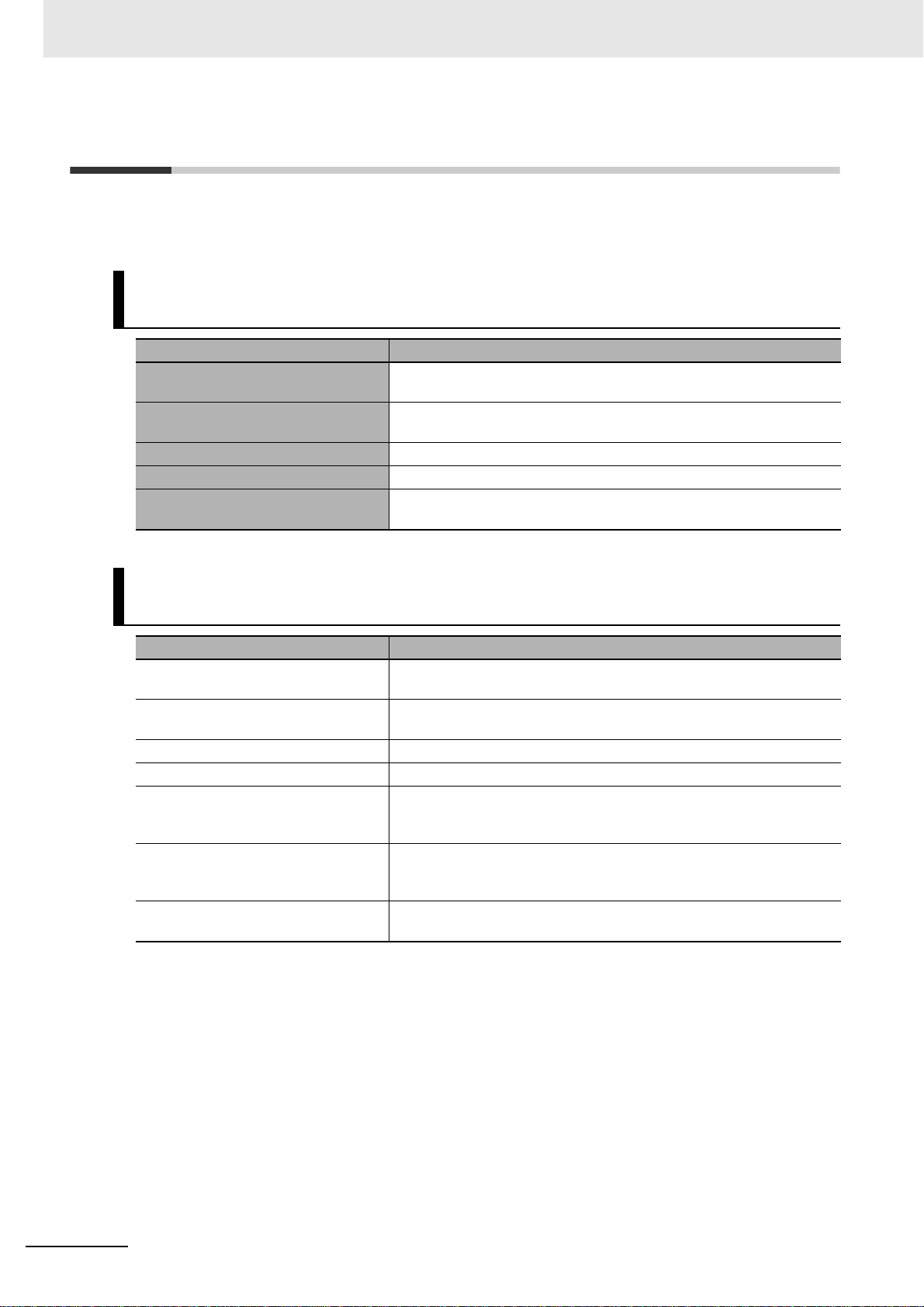
Programmable Terminals Setup Manual (Cat. No. V107)
(This Manual)
Section Contents
Section 1 Part Names and Functions This section describes the names and functions of the various parts of
Section 2 Installing the NB Unit and
Connecting Peripheral Devices
Section 3 System Setting Mode This section describes the System Setting Mode.
Section 4 Calibrate Mode This section describes the Calibrate Mode.
Appendices The appendices provide information on specifications, dimensions,
an NB Unit.
This section describes the methods used to install the NB Unit and
connect peripheral devices.
wirings, and lists of the NB Units, the applicable PLCs and options.
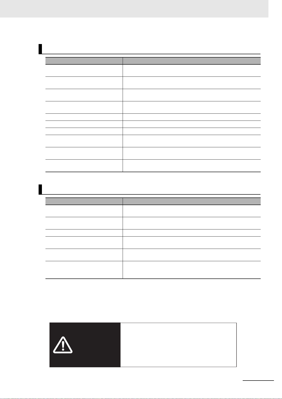
Programmable Terminals NB-Designer Operation Manual
(Cat. No. V106)
Section Contents
Section 1 Introduction This section provides an outline of the NB-series PTs, including their
functions, features, connection types and communication methods.
Section 2 Installation and Startup of
NB-Designer
Section 3 Functions of NB-Designer This section describes the functions of NB-Designer.
Section 4 Functions of NBManager This section describes the functions of NBManager.
Section 5 Maintenance and
Abnormality Handling
Section 6 Descriptions of New
Functions Added into NBTW01B
Appendices The appendices provide lists of the NB Units, the Communication Units,
This section describes how to install and start the NB-Designer.
This section describes the maintenance and check to prevent the
abnormality occurrence and the handling of the abnormalities occurred
in NB Unit.
This section describes the new functions added into NB-TW01B,
the system attributes and the component attributes.
the applicable PLCs, and the list of NB-Designer functions.
2
NB-series Programmable Terminals Setup Manual(V107)
WWW.NNC.IR
Page 6
Programmable Terminals Host Connection Manual (Cat. No. V108)
Section Contents
Section 1 List for All PLCs
Supported by NB series
Section 2 Connecting to SIEMENS
PLCs
Section 3 Connecting to Mitsubishi
PLCs
Section 4 Connecting to Schneider
PLCs
Section 5 Modbus Connection This section describes the connection on Modbus protocol.
Section 6 Connecting to Delta PLCs This section describes the connection to Delta PLCs.
Section 7 Connecting to LG PLCs This section describes the connection to LG PLCs.
Section 8 Connecting to Panasonic
PLCs
Section 9 Connecting to AllenBradley (Rockwell) PLC
Section 10 Connecting to PLC of GE
Fanuc Automation Inc.
This section lists all PLCs supported by NB Units.
This section describes the connection to SIEMENS PLCs.
This section describes the connection to Mitsubishi PLCs.
This section describes the connection to Schneider PLCs.
This section describes the connection to Panasonic PLCs.
This section describes the connection to Allen-Bradley PLC.
This section describes the connection to PLC of GE Fanuc Automation
Inc.
Programmable Terminals Startup Guide Manual (Cat. No. V109)
Section Contents
Section 1 NB Overview This section provide specifications of the NB Unit, describes its names
and functions of the various parts.
Section 2 System Design This section describes the manual structure, takes NB7W as an
example to introduce the operation procedures of the NB system.
Section 3 Installation and Wiring This section describes how to install and wire the NB Unit.
Section 4 Screen Creation This section describes how to create a demonstration project through
NB-Designer.
Section 5 Run This section describes how to start running at the Host side and
prepare to send screen data to NB7W.
Section 6 Maintenance and
Troubleshooting
This section describes the maintenance and inspection methods for
preventing errors occurring, and troubleshooting measures when errors
occur.
WARNING
NB-series Programmable Terminals Setup Manual(V107)
Failure to read and understand the information
provided in this manual may result in personal injury
or death, damage to the product, or product failure.
Please read each section in its entirety and be sure
you understand the information provided in the
section and related sections before attempting any
of the procedures or operations given.
3
WWW.NNC.IR
Page 7
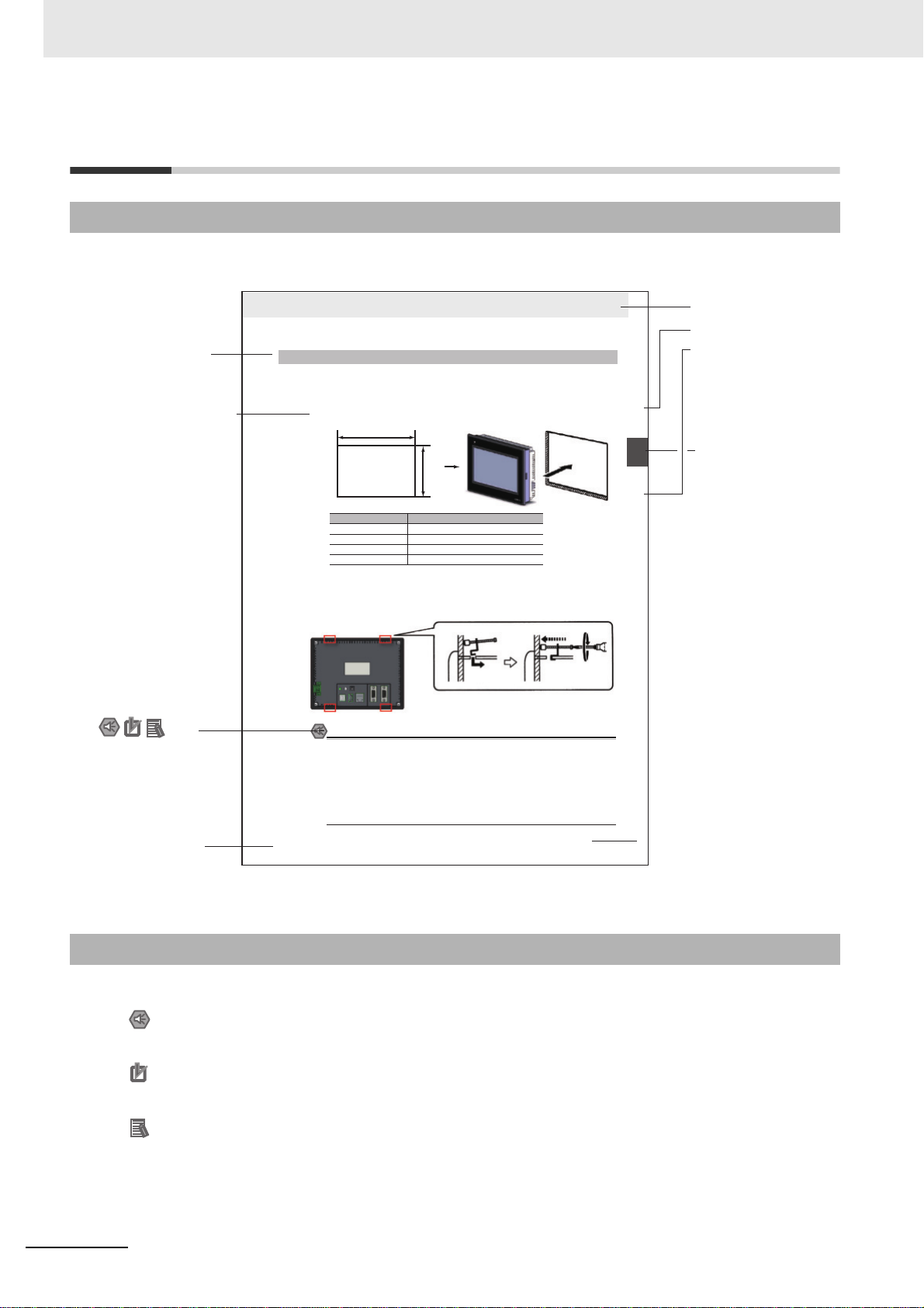
Manual Structure
Page Structure and Icons
The following page structure and icons are used in this manual.
Level 3 heading
Step in a procedure
Indicates a step in a
procedure.
Special Information
(See below.)
Icons are used to indicate
precautions and
additional information.
2 Installing the NB Unit and Connecting Peripheral Devices
2-1-2 Installation onto the Operation Panel
Install the NB Unit by embedding it into the operation panel.
Use the metal kit and tool (a crosshead screwdriver) supplied with the Unit for installation.
Proceed the installation following the procedures below.
1
Panel cutout with dimensions is shown below. Fit the NB Unit into the panel from the front side.
Width
Opening dimensions
Models Opening Dimension (W H mm)
NB3Q-TW00B/TW01B 119.0(+0.5/-0) 93.0(+0.5/-0)
NB5Q-TW00B/TW01B 172.4(+0.5/-0) 131.0(+0.5/-0)
NB7W-TW00B/TW01B 191.0(+0.5/-0) 137.0(+0.5/-0)
NB10W-TW01B 258.0(+0.5/-0) 200.0(+0.5/-0)
2
As follows, insert panel fixators at the locations indicated by red box around the back of the NB Unit.
Insert the hooks of positioners into the square holes on the Unit to hold the fixators properly, and
tighten the screws firmly with the screwdriver.
NB5Q/NB7W-TWB
Precautions for Safe Use
• When operating on the operation panel, make sure to keep metal particles from entering the
Unit.
The mounting panel must be between 1.6 and 4.8 mm thick. The NB Unit must be installed
in a control panel.
For the sake of waterproof and dustproof, all the fixators must be evenly tightened to a
torque of 0.5~0.6 Nm. If the tightening torque exceeds the specified value, or the tightening
is not even, deformation of the front panel may occur.
Make sure that the operation panel is clean, unbent, and strong enough for the installation
process.
Height
2-1 Installing the NB Unit
2
2-1-2 Installation onto the Operation Panel
Level 1 heading
Level 2 heading
Level 3 heading
Gives the current
headings.
Page tab
Gives the number
of the section.
Manual name
This illustration is provided only as a sample and may not literally appear in this manual.
Special Information
Special information in this manual is classified as follows:
Precautions for Safe Use
Precautions on what to do and what not to do to ensure using the product safely.
Precautions for Correct Use
Precautions on what to do and what not to do to ensure proper operation and performance.
Additional Information
Additional information to increase understanding or make operation easier.
4
NB-series Programmable Terminals Setup Manual(V107)
WWW.NNC.IR
2-3
NB-series Programmable Terminals Setup Manual(V107)
Page 8

Terminology
The following terminology is used in this manual.
Ter ms Descriptions
NB Unit Indicates the main Unit of the products in the OMRON NB Series of Programmable
NB Series Indicates products in the OMRON NB Series of Programmable Terminal.
PLC Indicates a Programmable Controller.
CP Series Indicates the following products in the OMRON CP Series of Programmable Controllers:
CS/CJ Series Indicates the following products in the OMRON CS/CJ Series of Programmable
C Series Indicates the following products in the OMRON C Series of Programmable Controllers:
Serial Communication
Unit
Serial Communication
Board
Communication Board Indicates a Communication Board for an OMRON C200HX/HG/HE(-Z) PLC.
CPU Unit Indicates a CPU Unit in the OMRON CP, CS/CJ or SYSMAC C Series of Programmable
NB-Designer Indicates the OMRON NB-Designer.
Host Indicates the PLC and other units functioning as the control devices for NB-Series
PT Indicates an OMRON Programmable Terminal.
HMI Indicates an OMRON Programmable Terminal.
Te r mi n a l .
In this manual, unless otherwise specified, NB Series is taken as the subject
concerned.
CP1H, CP1L, CP1E
Controllers: CS1G, CS1H, CS1G-H, CS1H-H, CJ1G, CJ1M, CJ2M, CJ2H
C200HX(-Z), C200HG(-Z), C200HE(-Z), CQM1, CQM1H, CPM1A, CPM2A, CPM2C
Indicates a Serial Communication Unit for an OMRON SYSMAC CS/CJ-Series PLC.
Indicates a Serial Communication Board for an OMRON SYSMAC CS/CJ-Series PLC.
Controllers.
Units.
NB-series Programmable Terminals Setup Manual(V107)
5
WWW.NNC.IR
Page 9

6
NB-series Programmable Terminals Setup Manual(V107)
WWW.NNC.IR
Page 10

CONTENTS
Introduction............................................................................................................... 1
NB-series Manuals.................................................................................................... 2
Manual Structure ...................................................................................................... 4
Terminology .............................................................................................................. 5
Safety Precautions ................................................................................................. 12
Precautions for Safe Use ....................................................................................... 14
Precautions for Correct Use .................................................................................. 16
Conformance to EC Directives .............................................................................. 17
Related Manuals ..................................................................................................... 18
Sec. 1 Part Names and Functions.................................................... 1-1
1-1 Part Names............................................................................................................................... 1-2
1-2 Part Specifications .................................................................................................................. 1-6
Sec. 2 Installing the NB Unit and Connecting Peripheral Devices2-1
2-1 Installing the NB Unit .............................................................................................................. 2-2
2-1-1 Installation environment.............................................................................................................. 2-2
2-1-2 Installation onto the Operation Panel.......................................................................................... 2-3
2-1-3 Connecting the Power Supply..................................................................................................... 2-5
2-1-4 Grounding Wiring........................................................................................................................ 2-6
2-2 Start of NB Series .................................................................................................................... 2-7
2-3 Connecting of NB-series with PC .......................................................................................... 2-8
2-3-1 Connecting by RS-232C............................................................................................................. 2-8
2-3-2 Connecting by USB .................................................................................................................... 2-9
2-3-3 Connecting by Ethernet ............................................................................................................ 2-10
2-4 Serial Communication Connection...................................................................................... 2-11
2-4-1 Host Link Connection Method................................................................................................... 2-11
2-4-2 Connecting more than one PLC ...............................................................................................2-12
2-4-3 Settings for each Unit ............................................................................................................... 2-13
2-5 FINS/UDP Communication Connection............................................................................... 2-26
2-5-1 Connecting to Host Via Ethernet .............................................................................................. 2-26
2-5-2 Parameter Settings for FINS/UDP at NB Side .......................................................................... 2-29
2-5-3 Host Types and Settings of Ethernet Unit................................................................................. 2-31
2-5-4 Host Types and Settings of Ethernet/IP Unit ............................................................................ 2-38
2-5-5 Parameter Settings for FINS/UDP at Host Side........................................................................ 2-42
Sec. 3 System Setting Mode............................................................. 3-1
3-1 Display Method of System Setting Mode .............................................................................. 3-2
3-2 Functions of System Setting Mode........................................................................................ 3-3
NB-series Programmable Terminals Setup Manual(V107)
WWW.NNC.IR
7
Page 11

Sec. 4 Calibrate Mode ....................................................................... 4-1
4-1 Display Method of Calibrate Mode......................................................................................... 4-2
4-2 Functions of Calibrate Mode ..................................................................................................4-2
4-3 On-line Touch-control Calibration Function.......................................................................... 4-2
Sec. A Appendices.............................................................................A-1
A-1 Specifications .........................................................................................................................A-2
A-1-1 General Specifications ................................................................................................................A-2
A-1-2 Performance Specifications.........................................................................................................A-2
A-1-3 Communication Specifications....................................................................................................A-4
A-2 External Dimensions ...............................................................................................................A-5
A-3 RS-422A/485 Connections ......................................................................................................A-7
A-3-1 Grounding and Shielding of the Cables ......................................................................................A-7
A-4 Fabrication of the Connection Cable.....................................................................................A-9
A-4-1 Cable Processing........................................................................................................................A-9
A-4-2 Soldering...................................................................................................................................A-10
A-4-3 Shield Assembly........................................................................................................................A-10
A-4-4 Method for Fabricating the Cable for Connection to OMRON PLC...........................................A-11
A-4-5 Method for fabricating the cable for connection to PC ..............................................................A-13
A-5 List of Models ........................................................................................................................A-14
A-6 List of Options .......................................................................................................................A-19
Revision History........................................................................................................ 1
8
WWW.NNC.IR
NB-series Programmable Terminals Setup Manual(V107)
Page 12

Read and Understand this Manual
Please read and understand this manual before using the product. Please consult your OMRON representative
if you have any questions or comments.
Warranty and Limitations of Liability
WARRANTY
OMRON’s exclusive warranty is that the products are free from defects in materials and workmanship for a
period of one year (or other period if specified) from date of sale by OMRON.
OMRON MAKES NO WARRANTY OR REPRESENTATION, EXPRESS OR IMPLIED, REGARDING NONINFRINGEMENT, MERCHANTABILITY, OR FITNESS FOR PARTICULAR PURPOSE OF THE
PRODUCTS. ANY BUYER OR USER ACKNOWLEDGES THAT THE BUYER OR USER ALONE HAS
DETERMINED THAT THE PRODUCTS WILL SUITABLY MEET THE REQUIREMENTS OF THEIR
INTENDED USE. OMRON DISCLAIMS ALL OTHER WARRANTIES, EXPRESS OR IMPLIED.
LIMITATIONS OF LIABILITY
OMRON SHALL NOT BE RESPONSIBLE FOR SPECIAL, INDIRECT, OR CONSEQUENTIAL DAMAGES,
LOSS OF PROFITS OR COMMERCIAL LOSS IN ANY WAY CONNECTED WITH THE PRODUCTS,
WHETHER SUCH CLAIM IS BASED ON CONTRACT, WARRANTY, NEGLIGENCE, OR STRICT
LIABILITY.
In no event shall the responsibility of OMRON for any act exceed the individual price of the product on which
liability is asserted.
IN NO EVENT SHALL OMRON BE RESPONSIBLE FOR WARRANTY, REPAIR, OR OTHER CLAIMS
REGARDING THE PRODUCTS UNLESS OMRON’S ANALYSIS CONFIRMS THAT THE PRODUCTS
WERE PROPERLY HANDLED, STORED, INSTALLED, AND MAINTAINED AND NOT SUBJECT TO
CONTAMINATION, ABUSE, MISUSE, OR INAPPROPRIATE MODIFICATION OR REPAIR.
NB-series Programmable Terminals Setup Manual(V107)
9
WWW.NNC.IR
Page 13

Application Considerations
SUITABILITY FOR USE
OMRON shall not be responsible for conformity with any standards, codes, or regulations that apply to the
combination of products in the customer’s application or use of the products.
At the customer’s request, OMRON will provide applicable third party certification documents identifying
ratings and limitations of use that apply to the products. This information by itself is not sufficient for a
complete determination of the suitability of the products in combination with the end product, machine,
system, or other application or use.
The following are some examples of applications for which particular attention must be given. This is not
intended to be an exhaustive list of all possible uses of the products, nor is it intended to imply that the uses
listed may be suitable for the products:
• Outdoor use, uses involving potential chemical contamination or electrical interference, or conditions or
uses not described in this manual.
• Nuclear energy control systems, combustion systems, railroad systems, aviation systems, medical
equipment, amusement machines, vehicles, safety equipment, and installations subject to separate
industry or government regulations.
• Systems, machines, and equipment that could present a risk to life or property.
Please know and observe all prohibitions of use applicable to the products.
NEVER USE THE PRODUCTS FOR AN APPLICATION INVOLVING SERIOUS RISK TO LIFE OR
PROPERTY WITHOUT ENSURING THAT THE SYSTEM AS A WHOLE HAS BEEN DESIGNED TO
ADDRESS THE RISKS, AND THAT THE OMRON PRODUCTS ARE PROPERLY RATED AND INSTALLED
FOR THE INTENDED USE WITHIN THE OVERALL EQUIPMENT OR SYSTEM.
PROGRAMMABLE PRODUCTS
OMRON shall not be responsible for the user’s programming of a programmable product, or any
consequence thereof.
10
NB-series Programmable Terminals Setup Manual(V107)
WWW.NNC.IR
Page 14

Disclaimers
CHANGE IN SPECIFICATIONS
Product specifications and accessories may be changed at any time based on improvements and other
reasons.
It is our practice to change model numbers when published ratings or features are changed, or when
significant construction changes are made. However, some specifications of the products may be changed
without any notice. When in doubt, special model numbers may be assigned to fix or establish key
specifications for your application on your request. Please consult with your OMRON representative at any
time to confirm actual specifications of purchased products.
DIMENSIONS AND WEIGHTS
Dimensions and weights are nominal and are not to be used for manufacturing purposes, even when
tolerances are shown.
PERFORMANCE DATA
Performance data given in this manual is provided as a guide for the user in determining suitability and does
not constitute a warranty. It may represent the result of OMRON’s test conditions, and the users must
correlate it to actual application requirements. Actual performance is subject to the OMRON Warranty and
Limitations of Liability.
ERRORS AND OMISSIONS
The information in this manual has been carefully checked and is believed to be accurate; however, no
responsibility is assumed for clerical, typographical, or proofreading errors, or omissions.
NB-series Programmable Terminals Setup Manual(V107)
11
WWW.NNC.IR
Page 15
Safety Precautions
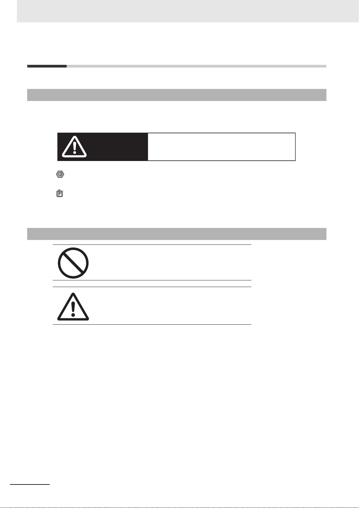
Notation Used for Safety Information
The following notation is used in this manual to provide precautions required to ensure safe usage of
the product. The safety precautions that are provided are extremely important to safety. Always read
and heed the information provided in all safety precautions.
Indicates an imminently hazardous situation which,
WARNING
Precautions for Safe Use
Indicates precautions on what to do and what not to do to ensure using the product safely.
if not avoided, will result in death or serious injury.
Additionally, there may be severe property damage.
Note Indicates suggestive information and precautions on operation of the product.
Symbols
Precautions for Correct Use
Indicates precautions on what to do and what not to do to ensure proper operation
and performance.
• Prohibition
Indicates a general prohibition.
• Caution
Indicates general cautionary, warning, or danger level
information.
12
NB-series Programmable Terminals Setup Manual(V107)
WWW.NNC.IR
Page 16
WARNING
Do not attempt to take the product apart and do not touch the product inside while the
power is being supplied. Otherwise it may result in electric shock.
Always ensure that the personnel in charge confirm that installation, inspection, and
maintenance were properly performed for the NB Unit.
“Personnel in charge” refers to individuals qualified and responsible for ensuring
safety during machine design, installation, operation, maintenance, and disposal.
Ensure that installation and post-installation checks are performed by personnel in
charge who possess a thorough understanding of the machinery to be installed.
Do not use the input functions of the touch switch, etc. of the NB Unit, in applications
that involve human life, in applications that may result in serious injury, or for
emergency stop switches.
Do not attempt to disassemble, repair, or modify the NB Unit. Otherwise it may impair
the safety functions.
Never press more than two points on the touch panel of the NB Unit at a time.
Otherwise, it may activate a switch somewhere between the two points.
NB-series Programmable Terminals Setup Manual(V107)
13
WWW.NNC.IR
Page 17

Precautions for Safe Use
• When unpacking the NB Units and the peripheral devices, check carefully for any external scratches
or other damages. Also, shake the Units gently and check for any abnormal sound.
• The NB Unit must be installed in a control panel.
• The mounting panel must be between 1.6 and 4.8 mm thick. Tighten the Mounting Brackets evenly to
a torque of between 0.5 and 0.6 N
exceeds the specified value, or the tightening is not even, deformation of the front panel may occur.
What is more, make sure the panel is not dirty or warped and that it is strong enough to hold the
Units.
• Do not let metal particles enter the Units when preparing the panel.
• Do not connect an AC power supply to the DC power terminals.
• Use a DC power with a slight voltage fluctuation and that will provide a stable output even if the input
is momentarily interrupted for 10 ms.
Rated Power Supply Voltage: DC 24 V (Allowable range DC 20.4 ~ 27.6 V)
• Do not perform a dielectric voltage test.
• Making the connection by using terminal screws crimping on a twisted-pair cable with a crimping
range of 12~26 AWG, and only 6.5 mm of insulation peel of the cable needs to be peeled off. Tighten
the terminal screws at a torque of between 0.3 and 0.5 N
tightened.
• To prevent malfunctions caused by noise, ground the Unit correctly.
• Do not touch the packaging part of the circuit board with your bare hands. Discharge any static
electricity from your body before handling the board.
• When using the No. 6 pin of the serial communication port COM1 connector for a voltage of DC+5V,
make sure the supply equipment’s current capacity is below 250mA before using it. The DC+5V
voltage output of the NB unit is +5V±5%, and the maximum current is 250mA. (The serial
communication port COM1 of NB3Q-TW00B and NB3Q-TW01B is unable to output the current.)
• Turn OFF the power supply before connecting or disconnecting cables.
• Always keep the connector screws firmly tightened after the communication cable is connected.
• The maximum tensile load for cables is 30 N. Do not apply loads greater than this.
• Confirm the safety of the system before turning ON or OFF the power supply, or pressing the reset
button.
• The whole system may stop depending on how the power supply is turned ON or OFF. Turn ON/OFF
the power supply according to the specified procedure.
• Reset by pressing the reset button, or restart the power supply, once the DIP switch settings are
changed.
• To ensure the system’s safety, make sure to incorporate a program that can confirm the normal
functionality of the NB Unit before running the system.
• Start actual system application only after sufficiently checking screen data, macros and the operation
of the program at the host side.
• Do not press the touch panel with a force greater than 30 N.
• Do not use hard or pointed objects to operate or scrub the screen, otherwise, the surface of the
screen may be damaged.
• Confirm the safety of the system before pressing the touch panel.
• Signals from the touch switches may not be input if the touch switches are pressed consecutively at
high speed. Confirm each input before proceeding to the next one.
• Do not accidentally press the touch panel when the backlight is not lit or when the display does not
appear. Make sure of the safety of the system before pressing the touch panel.
• To use numeric input functions safely, always make maximum and minimum limit settings.
• Before initializing screen data, confirm that existing data is backed up at the NB-Designer.
m to maintain water and dust resistance. If the tightening torque
m. Make sure the screws are properly
14
NB-series Programmable Terminals Setup Manual(V107)
WWW.NNC.IR
Page 18

• When changing the password with the screen, do not reset or turn OFF the power supply until writing
is finished. Failure to save the password may cause the screen to fail to function.
• When using an equipment monitor, confirm the safety of the system before carrying out the following
operations:
• Changing monitor data.
• Changing operation mode.
• Forced setup/reset.
• Changing the current value or the set value.
• Do not connect a USB connector to any device that is not applicable.
• When connecting the equipment with the USB HOST connector, make sure the supply equipment’s
current capacity is below 150mA before using it. The DC+5V voltage output of the NB Unit is
+5V±5%, and the maximum current is 150mA.
• Before connecting a USB connector to a device, make sure that the device is free of damage.
• Commercially available and the recommended USB HUBs are different from the general
specifications of the NB Unit. The unit may not function well in an environment subject to noise, static
electricity. Therefore, when using a USB HUB, employ sufficient noise and static electricity insulation
measures, or install it at a site free of noise or static electricity.
• While uploading or downloading screen data or system programs, do not perform the following
operations that may corrupt the screen data or the system program:
• Turning OFF the power supply of the NB Unit.
• Pressing the PT’s reset switch.
• Dispose of the Units and batteries according to local ordinances as they apply.
• When exporting products with lithium primary batteries containing perchlorate at 6ppb or above to or
delivering them through California, USA, the following precautionary measures have to be publicized.
Perchlorate material - applicable through special processing. Refer to
http://www.dtsc.ca.gov/hazardouswaste/perchlorate.
NB-Series products contain lithium primary batteries. When exporting products containing this kind of
batteries to or delivering them through California, USA, label all the product packages as well as the
appropriate delivery packages.
•
Do not use benzene, paint thinner, or other volatile solvents, and do not use chemically treated cloths.
• Do not dispose the Units together with general waste at waste yards. When disposing them, follow
the related local ordinances or rules.
• Customers may not replace the backlight lamp inside the NB Unit. Please contact OMRON’s
customer service center.
• Deterioration over time can cause the touch points to move. Calibrate the touch panel periodically.
• Water and oil resistance will be lost if the front sheet is torn or is peeling off. Do not use the Unit, if the
front sheet is torn or is peeling off.
• The rubber packing will deteriorate, shrink, or harden depending on the operating environment.
Inspect and replace the rubber packing periodically.
• The communication cables of the COM1 and COM2 connectors are not interchangeable. Confirm the
pins of the ports before carrying out communications. (NB3Q-TW00B and NB3Q-TW01B only have
COM1.)
• Periodically check the installation conditions in applications where the PT is subject to contact with oil
or water.
• Do not perform the following operations during the communication of the USB memory:
• Turning off the power supply of the NB Unit.
• Pressing the Reset button on the NB Unit.
• Removing the USB memory.
• Do not use the USB memory in the environment subject to strong vibration.
NB-series Programmable Terminals Setup Manual(V107)
15
WWW.NNC.IR
Page 19

Precautions for Correct Use
• Do not install the unit in any of the following locations:
Locations subject to severe changes in temperature
Locations subject to temperatures or humidity outside the range specified in the specifications
Locations subject to condensation as the result of high humidity
Locations subject to corrosive or flammable gases
Locations subject to strong shock or vibration
Locations outdoors subject to direct wind and rain
Locations subject to strong ultraviolet light
Locations subject to dust
Locations subject to direct sunlight
Locations subject to splashing oil or chemicals
• Take appropriate and sufficient countermeasures when installing systems in the following locations:
Locations subject to static electricity or other forms of noise
Locations subject to strong electric field or magnetic field
Locations close to power supply lines
Locations subject to possible exposure to radioactivity
• Precautions for software:
The update, restoration, uninstall and reinstallation of software in running status is prohibited in order
to guarantee the correct use of the product.
16
NB-series Programmable Terminals Setup Manual(V107)
WWW.NNC.IR
Page 20

Conformance to EC Directives
NB-Series Programmable Terminals are EMC compliant.
Concepts
OMRON products are electronic devices that are incorporated in machines and manufacturing
installations. OMRON PTs conform to the related EMC Directives (see note) so that the devices and
machines into which they are built can more easily conform to EMC Directives. The actual products
have been through inspections and are completely in accordance with EMC directives. However, when
they are built into customers’ systems, whether the systems also comply with these Directives is up to
the customers for further inspection.
EMC-related performance of OMRON PTs will vary depending on the configuration, wiring, and other
conditions of the OMRON equipment or control panel. The customer must, therefore, perform final
checks to confirm that the overall machine or device conforms to EMC standards.
Note The applicable EMC (Electromagnetic Compatibility) standards are as follows:
EMS (Electromagnetic sensitivity): EN61131-2: 2007
EMI (Electromagnetic Interference): EN61131-2: 2007
Conformance to EC Directives
NB-Series Programmable Terminals are EC compliant. Heed the following precautions in order to
ensure that the customer’s overall machine and device conform to EC Directives.
1
The PT must be installed in a control panel.
2
You must use reinforced insulation or double insulation for the DC power supply and the DC
power supply must have minimal voltage fluctuations and provide a stable output even if the
power supply input is interrupted for 10 ms.
3
The PTs conform to the standard EN 61131-2, but radiated emission characteristics (10m
regulations) may vary depending on the configuration of the control panel used, other devices
connected to the control panel, wiring, and other conditions. You must therefore confirm that the
overall machine or equipment complies with EC Directives.
4
This is a Class A product (Product for industry purpose). It may cause radio interference in
residential areas, in which case the user may be required to take adequate measures to reduce
interference.
NB-series Programmable Terminals Setup Manual(V107)
17
WWW.NNC.IR
Page 21

Related Manuals
The related manuals are as follows:
Devices and Software Manual Name Manual No.
NB series NB Series NB-Designer Operation Manual V106
NB Series Setup Manual (This manual) V107
NB Series Host Connection Manual V108
NB Series Startup Guide V109
PLC SYSMAC CP Series CP1L CPU Unit Operation Manual W462
SYSMAC CP Series CP1H/L CPU Unit Programming Manual W451
SYSMAC CP Series CP1H CPU Unit Operation Manual W450
SYSMAC CP Series CP1E CPU Unit Hardware USER’S
Manual
SYSMAC CP Series CP1E CPU Unit Software USER’S
Manual
SYSMAC C200HX/HG/HE(-E/-ZE) Installation Guide W302
SYSMAC C200HX/HG/HE Operation Manual W303
SYSMAC C200HX/HG/HE(-ZE) Operation Manual W322
SYSMAC CPM1A Operation Manual W317
SYSMAC CPM2A Operation Manual W352
SYSMAC CPM1/CPM1A/CPM2A/CPM2C/SRM1(-V2)
Programming Manual
SYSMAC CPM2C Operation Manual W356
SYSMAC CS1 Series CS1G/H Operation Manual W339
SYSMAC CS/CJ Series Serial Communications Boards and
Serial Communications Units Operation Manual
SYSMAC CJ Series CJ1G/H(-H) CJ1M CJ1G Operation
Manual
SYSMAC CS/CJ Series Programming Manual W394
SYSMAC CS/CJ Series INSTRUCTIONS Reference Manual W340
SYSMAC CS/CJ Series Programming Consoles Operation
Manual
SYSMAC CS/CJ Series Communications Commands
Reference Manual
SYSMAC CJ Series CJ2 CPU Unit Hardware USER’S Manual W472
SYSMAC CJ Series CJ2 CPU Unit Software USER’S Manual W473
SYSMAC CS/CJ Series CS1W/CJ1W-ETN21 (100Base-TX)
Ethernet Units Operation Manual Construction of Networks
SYSMAC CS/CJ Series CS1W/CJ1W-ETN21 (100Base-TX)
Ethernet Units Operation Manual Construction of Applications
SYSMAC CS/CJ Series CS1W/CJ1W-EIP21 (100Base-TX)
EtherNet/IP Units Operation Manual
SYSMAC CP Series CP1L-EL/EM CPU Unit Operation Manual
External Tool
CX-Programmer Ver.9.
Operation Manual
W479
W480
W353
W336
W393
W341
W342
W420
W421
W465
W516
W446
18
NB-series Programmable Terminals Setup Manual(V107)
WWW.NNC.IR
Page 22

\
Part Names and Functions
This section describes the names and functions of the various parts of an NB Unit.
1-1 Part Names . . . . . . . . . . . . . . . . . . . . . . . . . . . . . . . . . . . . . . . . . . . . . . . . . . . 1-2
1-2 Part Specifications . . . . . . . . . . . . . . . . . . . . . . . . . . . . . . . . . . . . . . . . . . . . . 1-6
1
NB-series Programmable Terminals Setup Manual(V107)
1-1
WWW.NNC.IR
Page 23
1 Part Names and Functions
y
1-1 Part Names
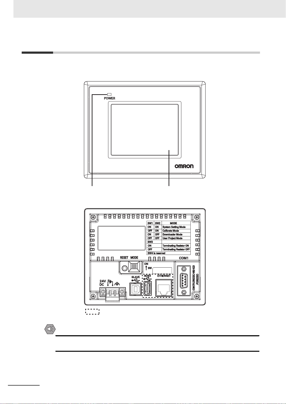
NB3Q-TW00B/NB3Q-TW01B model
Front view
Back view
Power Indicator Displa
: NB-TW01B only
1-2
Precautions for Safe Use
Confirm the safety of the system before turning ON or OFF the power supply, or pressing the
reset button.
NB-series Programmable Terminals Setup Manual(V107)
WWW.NNC.IR
Page 24
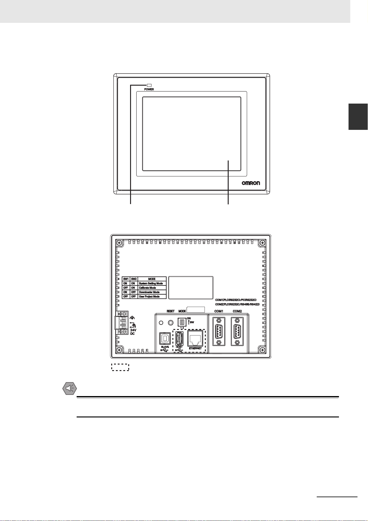
NB5Q-TW00B/NB5Q-TW01B model
Front view
1 Part Names and Functions
1-1 Part Names
1
Back view
Power Indicator
: NB-TW01B only
Display
Precautions for Safe Use
Confirm the safety of the system before turning ON or OFF the power supply, or pressing the
reset button.
NB-series Programmable Terminals Setup Manual(V107)
1-3
WWW.NNC.IR
Page 25

1 Part Names and Functions
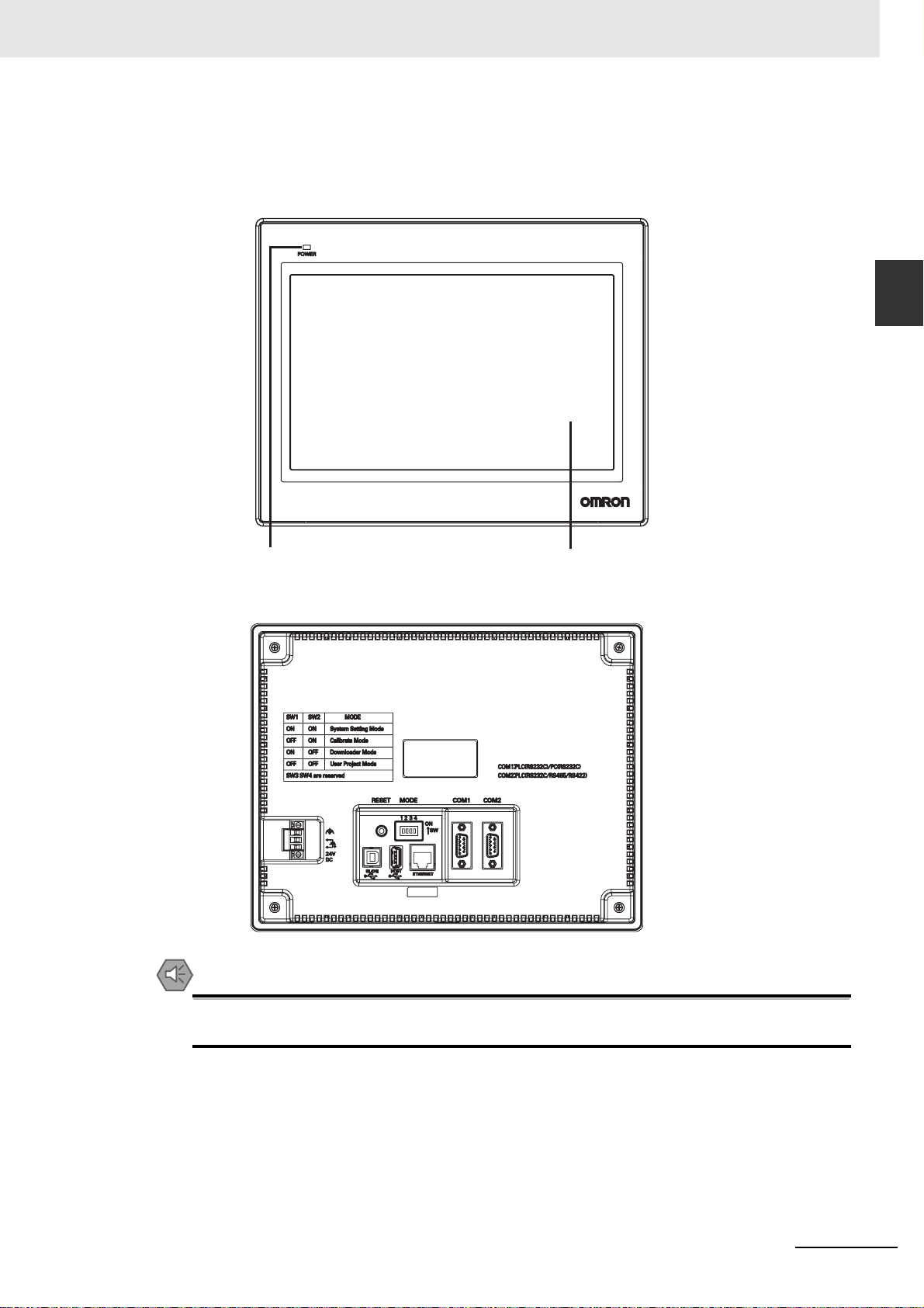
NB7W-TW00B/NB7W-TW01B model
Front view
Power Indicator
Back view
Precautions for Safe Use
Display
: NB-TW01B only
1-4
Confirm the safety of the system before turning ON or OFF the power supply, or pressing the
reset button.
NB-series Programmable Terminals Setup Manual(V107)
WWW.NNC.IR
Page 26
NB10W-TW01B model
Front view
1 Part Names and Functions
1-1 Part Names
1
Power Indicator
Back view
Precautions for Safe Use
Confirm the safety of the system before turning ON or OFF the power supply, or pressing the
reset button.
Display
NB-series Programmable Terminals Setup Manual(V107)
1-5
WWW.NNC.IR
Page 27
1 Part Names and Functions
1-2 Part Specifications
Touch Panel
Input operation can be carried out by means of the touch panel. By pressing the touch panel, the
screens can be switched, and the contact information can be transmitted to the host.
WARNING
Do not use the input functions of the touch switch, etc. of the NB Unit, in applications
that involve human life, in applications that may result in serious injury, or for
emergency stop switches.
Never press more than two points on the touch panel of the NB Unit at a time.
Otherwise, it may activate a switch somewhere between the two points.
Precautions for Safe Use
• Do not press a touch switch with a force greater than 30N.
• Do not accidentally press the touch panel when the backlight is not lit or when the display does
not appear. Make sure of the safety of the system before pressing the touch panel.
• Confirm the safety of the system before pressing the touch panel.
• Do not use hard or pointed objects to operate or scrub the screen, or the surface of the screen
may be damaged.
• Signals from the touch switches may not be input if the switches are pressed consecutively at
high speed. Confirm each input before proceeding to the next one.
• Deterioration over time can cause the touch points to move. Calibrate the touch panel
periodically.
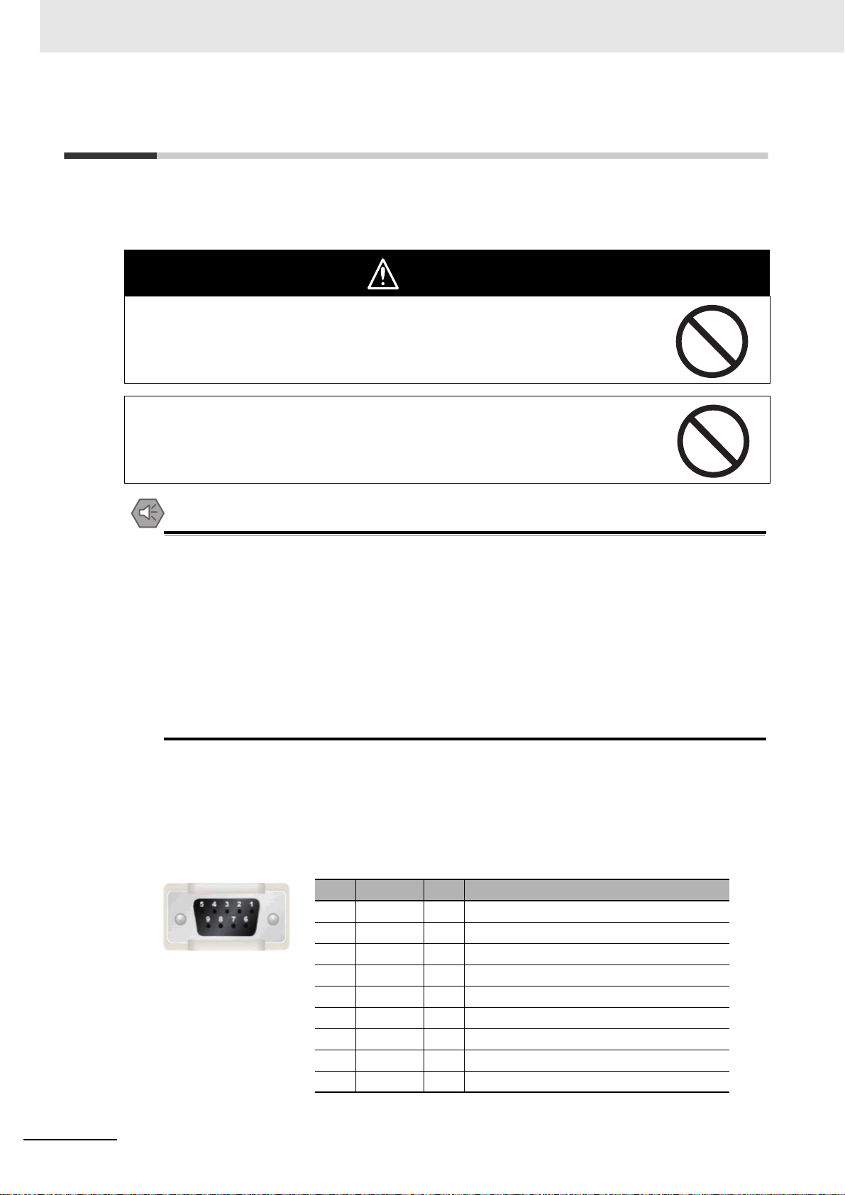
Serial Port COM1
• NB5Q/NB7W/NB10W-TWB
Serial port COM1 is a 9-pin D-type socket port. This port supports RS-232C communication
function, making it connectable to a controller which features RS-232C function, and it can also be
used for downloading programs or debugging for the product.
The pins are defined as follows:
Pins Signals I/O Functions
1NC - 2 SD O Sending data
3 RD I Receiving data
4 RS(RTS) O Request to send*
5 CS(CTS) I Clear to send*
6 DC+5V - DC+5V output (Max. current: 250mA)
7NC - 8NC - 9 SG - Signal ground
1-6
* Pins 4 and 5 are not used, thus not compliant with RS or CS functions.
NB-series Programmable Terminals Setup Manual(V107)
WWW.NNC.IR
Page 28

1 Part Names and Functions
Precautions for Safe Use
When using the No. 6 pin of the serial communications port COM1 connector for a voltage of
DC+5V, make sure the supply equipment’s current capacity is below 250 mA before using it. The
DC+5V voltage output of the NB Unit is +5V±5%, and the maximum current is 250 mA.
• NB3Q-TWB
1-2 Part Specifications
NB3Q-TWB has only 1 serial port COM1, and this port supports communication based on
RS-232C, RS-422 and RS-485, of which only 1 connection mode can be applied at one time. By
means of the RS-232C mode (PIN 2~5), it can be connected to a controller based on RS-232C,
and can also be used for downloading programs, as well as debugging for the product (connected
to a PC). While with the RS-422 or the RS-485 mode (PIN 1, PIN 6~8), only a PLC can be
connected.
The pins are defined as follows:
Pins Signals I/O
1 SDB+ I/O - - Sending data(+)
2SD O
3RD I
4 RS(RTS) O
5 CS(CTS) I Clear to send* - 6 RDB+ I/O - RS485B
7 SDA- I/O - - Sending data(-)
8 RDA- I/O - RS485A
9 SG - Signal ground
RS-232C RS-485 RS-422A
PLC Sending data
PLC Receiving data
Request to send*
Functions
--
--
--
Send/Receive
data(+)
Send/Receive
data(-)
Receiving
data(+)
Receiving
data(-)
1
* Pins 4 and 5 are not used, thus not compliant with RS or CS functions.
Serial Port COM2
• NB5Q/NB7W/NB10W-TWB
Serial port COM2 is a 9-pin D-type socket port. This port supports RS-232C/RS-485/RS-422A
communication function.
The pins are defined as follows:
Pins Signals I/O
1 SDB+ I/O - - Sending data(+)
2 SD O Sending data - 3 RD I Receiving data - 4 Terminal R1 - - Terminal resistor 1
5 Terminal R2 - - Terminal resistor 2
6 RDB+ I/O - Send/Receive
7 SDA- I/O - - Sending data(-)
8 RDA- I/O - Send/Receive
9 SG - Signal ground
RS-232C RS-485 RS-422A
Functions
data(+)
data(-)
Receiving
data(+)
Receiving
data(-)
NB-series Programmable Terminals Setup Manual(V107)
1-7
WWW.NNC.IR
Page 29
1 Part Names and Functions
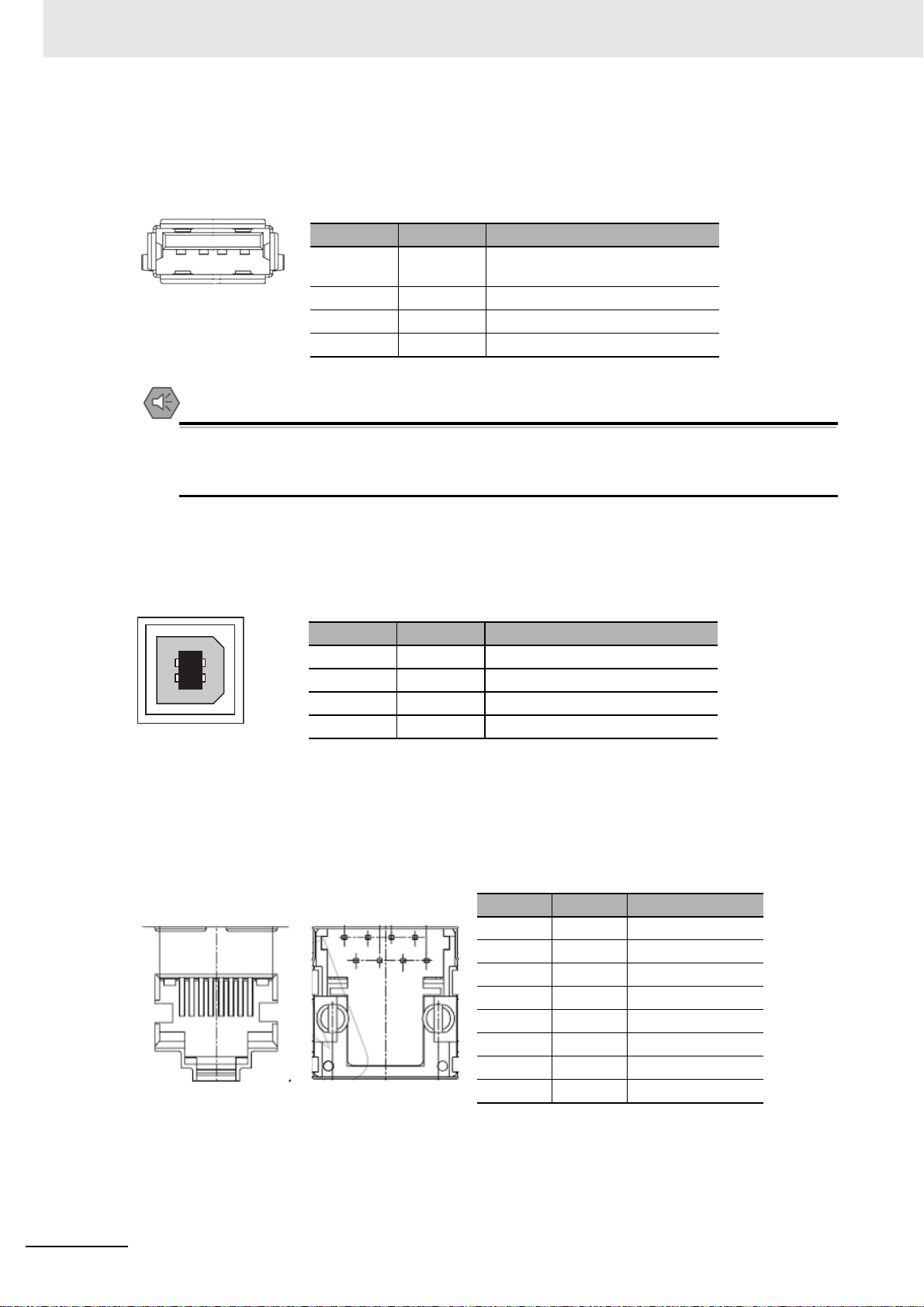
USB HOST
NB-TW01B is equipped with USB HOST port, which is USB A-type port. Through this port, USB
memory can be connected to perform uploading, downloading, project operation and storage of related
data. And its pins are defined as follows:
1 2 3 4
Precautions for Safe Use
When connecting the equipment with the USB HOST connector, make sure the supply
equipment’s current capacity is below 150mA before using it. The DC+5V voltage output of the
NB Unit is +5V±5%, and the maximum current is 150mA.
Pins Signals Functions
1 Vbus USB +5V power supply output
(Max. current: 150mA)
2 D- Data 3 D+ Data +
4 GND USB power supply ground
USB SLAVE
USB SLAVE port is USB B-type port, which can connect the USB port on PC side to perform the
uploading, downloading and debugging of the programs for the product. And its pins are defined as
follows:
Pins Signals Functions
3
41
2
1 Vbus USB +5V power supply output
2 D- Data 3 D+ Data +
4 GND USB power supply ground
Ethernet Interface
NB-TW01B is equipped with Ethernet Interface, which is adaptive RJ-45 type interface with the
transmission rate of 10M/100M. It can be connected with PC to perform the uploading and downloading
of the programs and the system refreshing, and can also be used to realize the communication with the
controller supporting the Ethernet communication. And its pins are defined as follows:
TOP Bottom
8
1
8
1
Pins Signals Functions
1 TD+ Sending data +
2 TD- Sending data 3 RD+ Receiving data +
4---Not used
5---Not used
6 RD- Receiving data 7---Not used
8---Not used
1-8
NB-series Programmable Terminals Setup Manual(V107)
WWW.NNC.IR
Page 30
1 Part Names and Functions
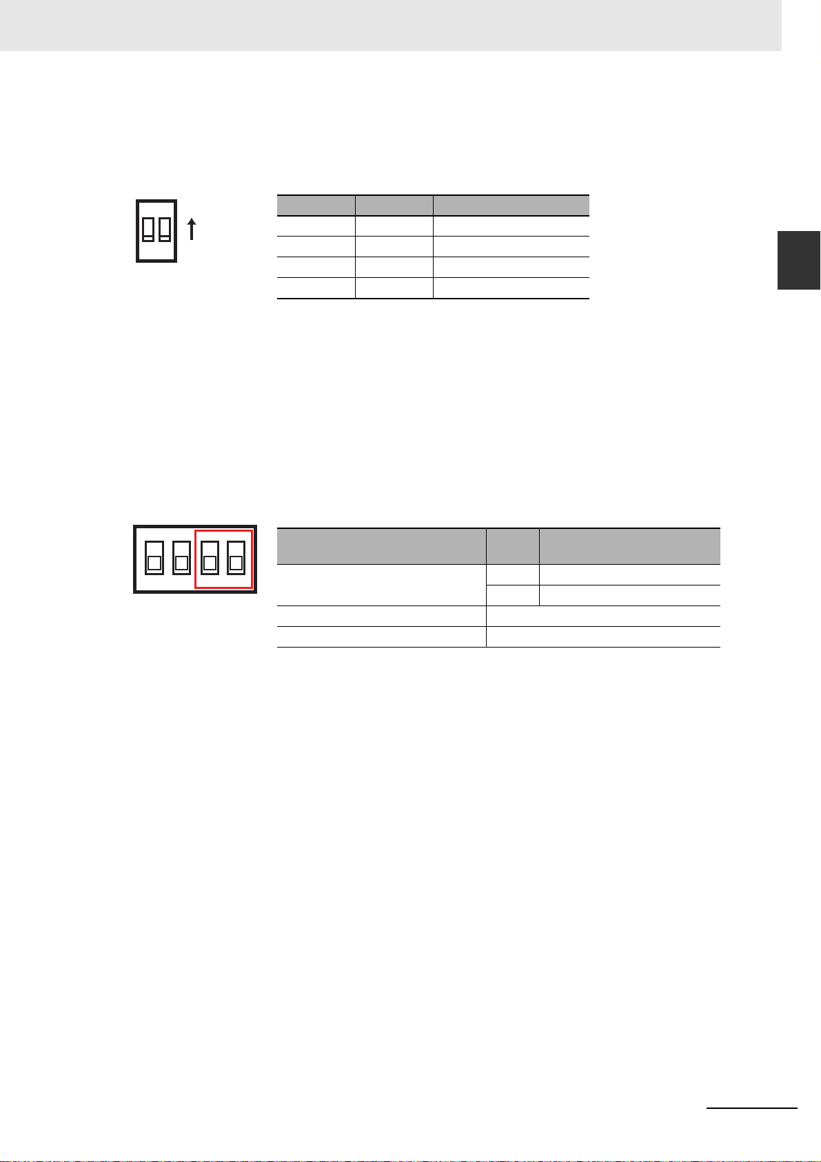
DIP Switch
NB5Q/NB7W only has 2 switches SW1 and SW2, while for the NB3Q and NB10W, there are totally 4
DIP switches, and for all models, SW1 and SW2 feature the same functions. The settings and
corresponding operating modes are as follows:
1-2 Part Specifications
ON
12
ON
SW1 SW2 Operating modes
ON ON System Setting Mode
OFF ON Calibrate Mode
ON OFF Downloader Mode
OFF OFF User Project Mode
• System Setting Mode: The PT will be launched into a built-in system setup screen, and is subject to
the user for brightness, system time and buzzer settings.
• Calibrate Mode: When the user touches the panel, a symbol “+” will pop up on the screen, with which
the touch control precision level can be calibrated.
• Downloader Mode: This is used for basic operations such as updating the firmware, downloading and
uploading the user’s engineering documents, etc. and this mode is not intended for general users.
• User Project Mode: This is the User Project Mode of NB-Series PTs. The PT will display the startup
screen of the project already downloaded.
As mentioned above, the settings and corresponding operating modes of the switches SW1 and SW2
of NB3Q and NB10W are the same as those of NB5Q/NB7W (see the table above), and the functions of
SW3 and SW4 of NB3Q and NB10W are stated as below:
ON
(corresponding model(s))
1
2
3
4
SW3 (NB3Q)
SW3 (NB10W) Reserved
SW4 (NB3Q/NB10W) Reserved
Switch No.
Status Descriptions of Function
ON Terminal resistance ON
OFF Terminal resistance OFF
1
Reset Switch
When pressing the reset switch located on the back side of the PT, the system will be rebooted.
NB-series Programmable Terminals Setup Manual(V107)
1-9
WWW.NNC.IR
Page 31

1 Part Names and Functions
1-10
NB-series Programmable Terminals Setup Manual(V107)
WWW.NNC.IR
Page 32

Ü
Installing the NB Unit and Connecting Peripheral Devices
This section describes the methods used to install the NB Unit and connect peripheral
devices.
2-1 Installing the NB Unit . . . . . . . . . . . . . . . . . . . . . . . . . . . . . . . . . . . . . . . . . . . 2-2
2-1-1 Installation environment . . . . . . . . . . . . . . . . . . . . . . . . . . . . . . . . . . . . . . . . . . 2-2
2-1-2 Installation onto the Operation Panel . . . . . . . . . . . . . . . . . . . . . . . . . . . . . . . . 2-3
2-1-3 Connecting the Power Supply . . . . . . . . . . . . . . . . . . . . . . . . . . . . . . . . . . . . . 2-5
2-1-4 Grounding Wiring . . . . . . . . . . . . . . . . . . . . . . . . . . . . . . . . . . . . . . . . . . . . . . . 2-6
2-2 Start of NB Series . . . . . . . . . . . . . . . . . . . . . . . . . . . . . . . . . . . . . . . . . . . . . 2-7
2-3 Connecting of NB-series with PC . . . . . . . . . . . . . . . . . . . . . . . . . . . . . . . . . 2-8
2-3-1 Connecting by RS-232C . . . . . . . . . . . . . . . . . . . . . . . . . . . . . . . . . . . . . . . . . 2-8
2-3-2 Connecting by USB . . . . . . . . . . . . . . . . . . . . . . . . . . . . . . . . . . . . . . . . . . . . . 2-9
2-3-3 Connecting by Ethernet . . . . . . . . . . . . . . . . . . . . . . . . . . . . . . . . . . . . . . . . . 2-10
2-4 Serial Communication Connection . . . . . . . . . . . . . . . . . . . . . . . . . . . . . . 2-11
2-4-1 Host Link Connection Method . . . . . . . . . . . . . . . . . . . . . . . . . . . . . . . . . . . . 2-11
2-4-2 Connecting more than one PLC . . . . . . . . . . . . . . . . . . . . . . . . . . . . . . . . . . 2-12
2-4-3 Settings for each Unit . . . . . . . . . . . . . . . . . . . . . . . . . . . . . . . . . . . . . . . . . . 2-13
2-5 FINS/UDP Communication Connection . . . . . . . . . . . . . . . . . . . . . . . . . . . 2-26
2-5-1 Connecting to Host Via Ethernet . . . . . . . . . . . . . . . . . . . . . . . . . . . . . . . . . . 2-26
2-5-2 Parameter Settings for FINS/UDP at NB Side . . . . . . . . . . . . . . . . . . . . . . . . 2-29
2-5-3 Host Types and Settings of Ethernet Unit . . . . . . . . . . . . . . . . . . . . . . . . . . . 2-31
2-5-4 Host Types and Settings of Ethernet/IP Unit . . . . . . . . . . . . . . . . . . . . . . . . . 2-38
2-5-5 Parameter Settings for FINS/UDP at Host Side . . . . . . . . . . . . . . . . . . . . . . . 2-42
2
NB-series Programmable Terminals Setup Manual(V107)
2-1
WWW.NNC.IR
Page 33

2 Installing the NB Unit and Connecting Peripheral Devices
2-1 Installing the NB Unit
This section describes the methods used to mount the NB Unit onto an operation panel and connect
the power supply.
2-1-1 Installation environment
When mounting the NB Unit onto the operation panel, pay attention to the following precautions.
WARNING
Always ensure that the personnel in charge confirm that installation, inspection, and
maintenance were properly performed for the NB Unit.
“Personnel in charge” refers to individuals qualified and responsible for ensuring
safety during machine design, installation, operation, maintenance, and disposal.
Ensure that installation and post-installation checks are performed by personnel in
charge who possess a thorough understanding of the machinery to be installed.
Precautions for Correct UsePrecautions for Correct Use
• Do not install the product in any of the following locations:
Locations subject to rapid changes in temperature
Locations subject to temperatures or humidity outside the range specified in the
specifications
Locations subject to condensation as the result of high humidity
Locations subject to corrosive or flammable gases
Locations subject to strong shock or vibration
Locations outdoors subject to direct wind and rain
Locations subject to strong ultraviolet light
Locations subject to dust
Locations subject to direct sunlight
Locations subject to splashing oil or chemicals
• Take appropriate and sufficient countermeasures when the product is used in the following
locations:
Locations subject to static electricity or other forms of noise
Locations subject to strong electric field or magnetic field
Locations close to power supply lines
Locations subject to possible exposure to radioactivity
2-2
Precautions for Safe Use
When unpacking the NB Units and the peripheral devices, check carefully for any external
scratches or other damage. Also, shake the Units gently and check for any abnormal sound.
NB-series Programmable Terminals Setup Manual(V107)
WWW.NNC.IR
Page 34

2 Installing the NB Unit and Connecting Peripheral Devices
2-1-2 Installation onto the Operation Panel
Install the NB Unit by embedding it into the operation panel.
Use the panel mounting brackets and Phillips screwdriver for installation.
Proceed the installation following the procedures below.
1
Panel cutout with dimensions is shown below. Fit the NB Unit into the panel from the front side.
Width
2-1 Installing the NB Unit
2
Opening dimensions
Models Opening Dimension (W¯H mm)
NB3Q-TW00B/TW01B 119.0(+0.5/-0)¯93.0(+0.5/-0)
NB5Q-TW00B/TW01B 172.4(+0.5/-0)¯131.0(+0.5/-0)
NB7W-TW00B/TW01B 191.0(+0.5/-0)¯137.0(+0.5/-0)
NB10W-TW01B 258.0(+0.5/-0)¯200.0(+0.5/-0)
2
As follows, insert the panel mounting brackets at the locations indicated by red box around the
back of the NB Unit. Insert the hooks of positioners into the square holes on the Unit to hold the
fixators properly, and tighten the screws firmly with the screwdriver.
NB5Q/NB7W-TWB
Height
2-1-2 Installation onto the Operation Panel
NB-series Programmable Terminals Setup Manual(V107)
2-3
WWW.NNC.IR
Page 35

2 Installing the NB Unit and Connecting Peripheral Devices
y
y
The insert positions on the body of NB3Q-TWB/NB10W-TW01B (same
fixing method as above)
NB3Q -TWB
NB10W -TWB
Precautions for Safe Use
• Do not let metal particles enter the Units when preparing the panel.
• The mounting panel must be between 1.6 and 4.8 mm thick. Tighten the Mounting Brackets
evenly to a torque of between 0.5 and 0.6 N·m to maintain water and dust resistance. If the
tightening torque exceeds the specified value, or the tightening is not even, deformation of
the front panel may occur. What is more, make sure the panel is not dirty or warped and that
it is strong enough to hold the Units.
Display Mode of NB Series touch panel
NB Series touch panel has 2 display modes: horizontal and vertical.
The display mode can be selected when dragging a HMI from the Graph element window into the
Construct Window.
2-4
Menu Task Bar
Horizontal displa
WWW.NNC.IR
Menu Task Bar
Vertical displa
NB-series Programmable Terminals Setup Manual(V107)
Page 36

2 Installing the NB Unit and Connecting Peripheral Devices
2-1-3 Connecting the Power Supply
Precautions for Safe Use
• Do not connect an AC power supply to the DC power terminals.
• Use a DC power with a slight voltage fluctuation and that will provide a stable output even if
the input is momentarily interrupted for 10 ms.
Rated Power Supply Voltage: DC 24 V (Allowable range DC 20.4 ~ 27.6 V)
Power Supply
The connectable power supply specifications are as follows: figure out a suitable power supply
specification so as to satisfy the requirement for power supply capacity.
Models Rated Voltage Allowable Voltage Range Power
NB3Q-TW00B DC24V DC20.4V to 27.6V 5W
NB3Q-TW01B 9W
NB5Q-TW00B 6W
NB5Q-TW01B 10W
NB7W-TW00B 7W
NB7W-TW01B 11W
NB10W-TW01B 14W
2-1 Installing the NB Unit
2
2-1-3 Connecting the Power Supply
NB5Q/NB7W/NB10W-TWB
The reverse side of NB
0V
24V
NB3Q -TWB
The reverse side of NB
0V
24V
MCCB
DC24V
MCCB
DC24V
Precautions for Safe Use
• Making the connection by using terminal screws crimping on a twisted-pair cable with a
crimping range of 12~26 AWG, and only 6.5 mm of insulation peel of the cable needs to be
peeled off. Tighten the terminal screws at a torque of between 0.3 and 0.5 N·m. Make sure
the screws are properly tightened.
NB-series Programmable Terminals Setup Manual(V107)
2-5
WWW.NNC.IR
Page 37

2 Installing the NB Unit and Connecting Peripheral Devices
2-1-4 Grounding Wiring
The NB Unit has a functional grounding terminal ( ).
Arrange the wiring according to the following conditions.
1
When a potential difference occurs between the NB Unit and the host, arrange the grounding as
illustrated. If the distance is too long to realize a single-point grounding, do not ground the
of the NB Unit.
2
When the NB Unit, and noise source equipment such as motors and inverters, etc. are installed
on the same panel, do not ground the of the NB Unit.
NB Unit Host
Single-point
grounding
Precautions for Safe Use
To prevent malfunctions caused by noise, ground the Unit correctly.
2-6
NB-series Programmable Terminals Setup Manual(V107)
WWW.NNC.IR
Page 38

2 Installing the NB Unit and Connecting Peripheral Devices
2-2 Start of NB Series
Confirm the hardware are all correctly connected, turn on the power supply, and start the NB-Series.
This part describes the operations of the NB Series when it starts.
When starting the NB Unit for the first time
(1) Confirm that the DIP switches SW1 and SW2 on the back side are both ON.
(2) Turn on the power supply of the NB Unit, and with the POWER LED on the front side
turning green, the NB Unit starts, entering into the System Setting Mode.
(3) Through the System Setup screen, the system time, starting window No., screen saving
time, buzzer and the screen brightness can be set. When the setup is finished, turn OFF
the power supply, turn OFF both of the DIP switches, SW1 and SW2, and then switch on
the power supply again.
When starting the NB Unit after downloading the screen data to it.
2-2 Start of NB Series
2
2-1-4 Grounding Wiring
(1) Confirm that the DIP switches SW1 and SW2 on the back side are both OFF.
(2) Turn on the power supply of the NB Unit, and with the POWER LED on the front side
turning green, the NB Unit starts.
(3) The starting screen of the screen data downloaded to the NB Unit will be shown.
Entering into Calibrate Mode
(1) Confirm that the DIP switches SW1 and SW2 on the back side are respectively OFF and
ON.
(2) Turn on the power supply of the NB Unit, and with the POWER LED on the front side
turning green, the NB Unit starts.
(3) When the user touches the panel, a symbol “+” will pop up on the screen, with which the
touch control precision level can be calibrated.
Precautions for Safe Use
Confirm the safety of the system before turning ON or OFF the power supply, or pressing the
reset button.
NB-series Programmable Terminals Setup Manual(V107)
2-7
WWW.NNC.IR
Page 39

2 Installing the NB Unit and Connecting Peripheral Devices
2-3 Connecting of NB-series with PC
In order to transmit the screen data established by the NB-Designer to the NB Unit, the NB Unit needs
to be connected to a PC with a RS-232C, USB or Ethernet cable.
2-3-1 Connecting by RS-232C
Take NB5Q/NB7W-TW01B as example:
Connect the RS-232C cable at the PC side to the serial port COM1 of the NB Unit.
Communication conditions
Select the downloader mode through the tool menu of the NB-Designer. For details, refer to 3-15
Download in the NB-Designer Operation Manual.
Communication cable
Users can make connection cables by themselves. For details, refer to A-4 Fabrication of the
Connection Cable in the NB Series Setup Manual.
2-8
NB-series Programmable Terminals Setup Manual(V107)
WWW.NNC.IR
Page 40

2 Installing the NB Unit and Connecting Peripheral Devices
2-3-2 Connecting by USB
Use the USB transmission cable to connect the USB A-type port on PC side with the USB SLAVE Btype port on NB Unit. As to the USB connection, there are some preparations and restrictions that need
to be done or heeded. Refer to the following content to ensure a correct connection.
Take NB5Q/NB7W-TW01B as example:
Connect the USB port at the PC side and the USB slave connector of the NB Unit.
2-3 Connecting of NB-series with PC
2
2-3-2 Connecting by USB
USB driver for the NB-Designer
A USB driver needs to be installed in the PC for the purpose of transmitting screen data through USB.
The USB driver should be installed at the first time when connecting the NB Unit to a PC.
Please refer to 2-4 Installation of USB-Driver for NB in the NB-Designer Operation Manual for details on
the USB driver.
Precautions for Safe Use
• Commercially available and the recommended USB HUBs are different from the general
specifications of the NB Unit. The Unit may not function well in an environment subject to
noise, static electricity. Therefore, when using a USB HUB, employ sufficient noise and
static electricity insulation measures, or install it at a site free of noise or static electricity.
• Do not connect a USB connector to any device that is not applicable.
• Before connecting a USB connector to a device, make sure that the device is free of
damage.
NB-series Programmable Terminals Setup Manual(V107)
2-9
WWW.NNC.IR
Page 41

2 Installing the NB Unit and Connecting Peripheral Devices
2-3-3 Connecting by Ethernet
HMI with model number of NB-TW01B (other than NB-TW00B) can perform the uploading &
downloading of data (such as user project and recipe etc.) and the refreshing of HMI firmware through
connecting the Ethernet cable with RJ45 connectors on both ends and the network interface on PC
side.
Ethernet Cable
Communication conditions
Select the corresponding download method by clicking the Download Way option in Tools menu of the
NB-Designer. For details, refer to 3-15 Download in the NB-Designer Operation Manual.
2-10
NB-series Programmable Terminals Setup Manual(V107)
WWW.NNC.IR
Page 42

2 Installing the NB Unit and Connecting Peripheral Devices
2-4 Serial Communication Connection
2-4-1 Host Link Connection Method
Host Link is a connection method in which one PLC is connected to one NB Unit. There are 2 kinds of
connection methods: RS-232C and RS-422A.
The RS-232C connection method using serial ports COM1/COM2
2-4 Serial Communication Connection
This is the simplest and most feasible method.
NB Unit
RS-232C cable
(maximum length: 15m)
The following cables are recommended.
XW2Z-200T (Cable length: 2m) by OMRON
XW2Z-500T (Cable length: 5m) by OMRON
Host
The RS-422A connection method using the serial port COM2
With this method, the communication distance can be extended to a maximum of 500m.
NB Unit
RS-422A cable
(maximum length: 500m)
2
2-4-1 Host Link Connection Method
Host
The following cables are recommended.
NB-RSEXT-2M (Cable length: 2m) by OMRON
Note please adopt 4-wire RS-422A connection, and Host Link does not support 2-wire RS-485 connection.
Connectable Units at the host side
When using OMRON PLCs, the Units with built-in Host Link function vary depending on models and
series. There is also the CPU Unit connected in a Host Link method through adding the serial
communication board or communication board.
When connecting, confirm the connected PLC’s series, model and the models of the installed circuit
board/Unit.
As to the Units at the host side which can be connected to NB series Unit by RS-232C or RS-422A
through a Host Link, refer to A-5 List of Models in the NB Series Setup Manual.
NB-series Programmable Terminals Setup Manual(V107)
2-11
WWW.NNC.IR
Page 43

2 Installing the NB Unit and Connecting Peripheral Devices
Communication setting
The communication settings need to be set as following values before carrying out communications in
the Use Host link.
Items Settings
Data bit 7bit
Stop bit 2bit
Parity check Even
Communication speed Any value, but the values for the NB Unit and the host must be the same.
Connected Unit No. 00
At the NB Unit side, these settings are made through the PT menu of the NB-Designer. For details, refer
to 3-10-8 COM1/COM2 Setting in the NB-Designer Operation Manual.
For communication settings at the host side, refer to the related PLC manuals as needed.
2-4-2 Connecting more than one PLC
Select the RS-232C method for COM1, and one from RS-232C, RS-422A and RS-485 for COM2
(NB3Q-TWB is not equipped with serial port COM2.).
PT with the model number of NB-TW01B, which supports Ethernet, can connect single PLC or
multiple PLCs simultaneously through the Ethernet (through the router). When connecting with multiple
PLCs, it can connect the Host manufactured by the same manufacture or different manufactures
simultaneously. (Note: At a certain time, only one from RS-232C, RS-422A and RS-485 can be
designated for COM2 to perform communications.)
The example of NB5Q/NB7W/NB10W-TW01B connecting with 3 PLCs simultaneously is as shown
below:
NB Unit
COM1 RS-232C cable
COM2 RS-232C/422A/485 cable
NB Unit 1
NB Unit 2
NB Unit 3
2-12
Ethernet cable
Precautions for Safe Use
• Always keep the connector screws firmly tightened after the communication cable is
connected.
• The maximum tensile load for cables is 30N. Do not apply loads greater than this.
• The communication cables of the COM1 and COM2 connectors are not interchangeable.
Confirm the pins of the ports before carrying out communications.
NB-series Programmable Terminals Setup Manual(V107)
WWW.NNC.IR
Page 44

2 Installing the NB Unit and Connecting Peripheral Devices
2-4-3 Settings for each Unit
When connecting with the serial communication ports, the settings for each Unit are as follows:
When connecting to CP-Series Units
CP1L-L14/L20/M30/M40/M60 models
CP1H-X40/XA40/Y20 models
CP1E-N14/N20 models
CP1E-N30/N40/N60/NA20 models
CP1E-EL20/EM30/EM40 models
2-4 Serial Communication Connection
2
PLC System Settings Area
Write settings directly into the [PLC System Settings Area] with a peripheral tool (CX-Programmer, etc.)
based on the model and port of the host.
Host model and Port No. Channel No. (*1) Write Value Setting
CP1L-M30/M40/M60, serial port 1
CP1H-X40/XA40/Y20, serial port 1
CP1L-EM30/EM40, serial port 1
CP1L-L14/L20, serial port 1
CP1L-M30/M40/M60, serial port 2
CP1H-X40/XA40/Y20, serial port 2
CP1L-EL20, serial port 1
CP1L-EM30/EM40, serial port 2
Host model and Port No. Channel No. Write Value Setting
CP1E-N14/N20, serial port 1
CP1E-N30/N40/N60/NA20,
serial port 1
CP1E-N30/N40/N60/NA20,
serial port 2
144 8000 Use Host Link
145 0000~000A(*2) Communication speed
147 0000~001F Unit number
160 8000 Use Host Link
161 0000~000A(*2) Communication speed
163 0000~001F Unit number
A617.15~12 0 Use Host Link
A617.11~08 0, 3~A(*2) Communication speed
A617.07~00 00 7 data bits, 2 stop bits, Even
A618.15~12 0 Use Host Link
A618.11~08 0, 3~A(*2) Communication speed
A618.07~00 00 7 data bits, 2 stop bits, Even
2-4-3 Settings for each Unit
*1 The channel No. of CP1L/H is PLC Setup area.
*2 The communication speed should be set to the same value as that of the NB Unit.
Settings for the front-side DIP Switches
Set the front-side DIP switches so as to validate the settings for [PLC System Settings Area].
Set the SW4 to OFF when serial port 1 is used, set SW5 to OFF when serial port 2 is used. As the
CP1L-L has only one serial port, it has no DIP switch SW5.
12345 6
ON
1234
CP1L-M
CP1H
NB-series Programmable Terminals Setup Manual(V107)
ON
CP1L-L
2-13
WWW.NNC.IR
Page 45

2 Installing the NB Unit and Connecting Peripheral Devices
When connecting to C-Series CPU Units
C200HX/HG/HE(-Z), CPM1, CPM2, CQM1H type CPU Units
Connection Methods
The connection methods for the CPU Units of different PLC models.
PLC Models RS-232C connection RS-422A connection
C200HX/HG/HE(-Z) • Connect to the RS-232C port built in the
CPU Unit
• Connect to the RS-232C port (Ports A,
B) of the serial communication board
CPM1A • Connect to the peripheral port with a
dedicated RS-232C adaptor
(CPM1-CIF01).
CPM2A • Connect to the RS-232C port built in the
CPU Unit
• Connect to the peripheral port with a
dedicated RS-232C adaptor
(CPM1-CIF01).
CPM2C • Connect to the RS-232C port built in the
CPU Unit or the peripheral port with a
dedicated conversion cable (CPM2CCN111 type, CS1W-CN118 type and
CS1W-CN114 type) (CPM2C-CN111
type is a cable that divides the Unit port
into the RS-232C port built in the CPU
Unit and the peripheral port. When
connecting to the peripheral port, a RS232C adaptor (CPM1-CIF01 type) is
also needed to be connected.)
CQM1H • Connect to the RS-232C port built in the
CPU Unit
• Connect to the peripheral port with a
conversion cable (CS1W-CN118 type)
Connect to the RS-232C port (Port 1) of
the serial communication board
• Connect to the RS-422A port (port A) of
• Connect to the peripheral port with a
• Connect to the peripheral port with a
• Connect to the peripheral port with a
• Connect to the RS-422A port (Port 2) of
the serial communication board
dedicated RS-422A adaptor
(CPM1-CIF11 type).
dedicated RS-422A adaptor
(CPM1-CIF11 type).
dedicated conversion cable (CPM2CCN111 type or CS1W-CN114 type) and
a RS-422A adaptor (CPM1-CIF11 type)
(CPM2C-CN111 type is a cable that
divides the Unit port into the RS-232C
port built in the CPU Unit and the
peripheral port).
the serial communication board
2-14
PLC System Settings Area
Write settings directly into the [PLC System Settings Area] (Data memory) with a peripheral tool (CXProgrammer, etc.) based on the model and port of the host.
For RS-232C
Host Model
The RS-232C port built in
C200HX/HG/HE(-Z),
CPM2A, CPM2C, CQM1H
CPM1A DM6650 0001 Use Host Link
Por t A of
C200HX/HG/HE(-Z) (*1)
Port 1 of CQM1H (*2)
Por t B of
C200HX/HG/HE(-Z) (*1)
Channel
No.
DM6645 0001 Use Host Link
DM6646 03(*3) Communication conditions are standard settings. (*4)
DM6648 0000 Unit No. 00
DM6651 03(*3) Communication conditions are standard settings. (*4)
DM6653 0000 Unit No. 00
DM6555 0001 Use Host Link
DM6556 03(*3) Communication conditions are standard settings. (*4)
DM6558 0000 Unit No. 00
DM6550 0001 Use Host Link
DM6551 03(*3) Communication conditions are standard settings. (*4)
DM6553 0000 Unit No. 00
Write
Val ue
WWW.NNC.IR
Setting
NB-series Programmable Terminals Setup Manual(V107)
Page 46

2 Installing the NB Unit and Connecting Peripheral Devices
*1 The RS-232C port of the Communication Board.
*2 The RS-232C port of the Serial Communication Board.
*3 is the set value of the communication speed. Set the communication speed to the same value as that of
the NB Unit.
*4 Standard settings of the Communication conditions are as follows:
Start bit: 1 bit, Data bit: 7 bit, Stop bit: 2 bit, parity check: even
For RS-422A
Host Model Channel No. Write Value Setting
Port A of
C200HX/HG/HE
(-Z) (*1)
Port 2 of
CQM1H (*2)
*1 The RS-422A port of the Communication Board
*2 The RS-422A port of the Serial Communication Board
*3 is the set value of the communication speed. Set the communication speed to the same value as that of
the NB Unit.
*4 Standard settings of the Communication conditions are as follows:
Start bit: 1 bit, Data bit: 7 bit, Stop bit: 2 bit, parity check: even
For operations on [PLC System Settings Area], refer to the manual of the PLC employed.
DM6555 0001 Use Host Link
DM6556 03(*3) Communication conditions are standard settings. (*4)
DM6558 0000 Unit No. 00
DM6550 0001 Use Host Link
DM6551 03(*3) Communication conditions are standard settings. (*4)
DM6553 0000 Unit No. 00
2-4 Serial Communication Connection
2
2-4-3 Settings for each Unit
Connection methods for CPM2C
CPM2C only has a connector with the same shape of the CS-Series’ peripheral port, but the signal
cables inside are classified as used for the RS-232C port built in the CPU Unit and for the peripheral
port. Therefore, when using CPM2C, differentiate between the settings for the RS-232C port built in the
CPU and for the peripheral port based on the conversion cable and port employed to ensure correct
use. Besides, when using a simple communication device (CPM2C-CIF21 type), connect to the RS232C port. For details, refer to the CPM2C Operation Manual (W356).
Use a self-made connection cable to connect the NB Unit and CPM2C. Connect to CPM2C’s built-in
RS-232C port instead of the peripheral port.
Port connected to the PT PLC System Settings
CS1W-CN118 type port(D-Sub 9-pin) Carry out settings for the built-in RS-232C port
CS1W-CN118 type
RS-232C port
(D-Sub 9-pin socket)
When using a simple communication device (CPM2C-CIF21 type), connect to the RS-232C port
directly.
CPM2C
RS-232C port
NB-series Programmable Terminals Setup Manual(V107)
2-15
WWW.NNC.IR
Page 47

2 Installing the NB Unit and Connecting Peripheral Devices
Settings for the front-side DIP Switches
To activate the settings of [PLC System Settings Area] (Data memory), set as follows according to the
PLC:
• For C200HX/HG/HE (-Z) and RS-232C of CQM1H
For C200HX/HG/HE(-Z)
Communication condition setting for the RS-232C port
Set the DIP switch 5 to OF, and activate the “settings” in
PLC system settings.
For CQM1H
• For CPM2A
Set the communication condition
setting switch to [OFF] (downwards).
2-16
• For CPM2C (Only the RS-232C port can be connected)
Carry out settings according to the using conditions of the peripheral
port and built-in RS-232C port.
• When connecting the PT to the built-in RS-232C port (connect the
device that needs to perform communications other than that within
the standard setting range)
Set SW1 to OFF
Set SW2 to ON
• When connecting the PT to the built-in RS-232C port (connect a
programming console to the peripheral port)
Set SW1 to OFF
Set SW2 to ON
NB-series Programmable Terminals Setup Manual(V107)
WWW.NNC.IR
Page 48

2 Installing the NB Unit and Connecting Peripheral Devices
Setting methods for communication board switches (For RS-422A)
• For C200HX/HG/HE (-Z)
Switch 1: Side (4-wire = RS-422A)
Switch 2: ON side (terminal resistance ON = Terminal resistance activated)
• For CQM1H
2-wire/4-wire switch (WIRE): side (4 wire = RS-422A)
Terminal resistance ON/OFF switch (TERM): ON side (terminal resistance ON = Terminal resistance
activated)
2-4 Serial Communication Connection
Serial Communication Board
(Lining Board Slot 1)
Set the terminal resistance
ON/OFF switch to ON(right side)
2-wire/4-wire Selector Switch
RS-422A: [4](4-wire) (right side)
RS-485: [z](2-wire) (left side)
Settings for the communication adaptor switch
• For RS-232C adaptor (CPM1-CIF01 type)
Set the mode setting switch to [HOST] (Up side).
2
2-4-3 Settings for each Unit
• For RS-422A adaptor (CPM1-CIF11 type)
Set the terminal resistance switch to ON (Up side)
NB-series Programmable Terminals Setup Manual(V107)
2-17
WWW.NNC.IR
Page 49

2 Installing the NB Unit and Connecting Peripheral Devices
When connecting to CS-Series CPU Units
For CS1G/H-CPU (-V1) types and CS1G/H-CPUH types
Connection Methods
Connect to the RS-232C port built in the CPU Unit or the RS-232C port of the communication board.
When connecting to the peripheral port, a connection cable dedicated for the peripheral port is needed
(CS1W-CN118 type).
Only RS-232C can be used for connection.
PLC System Settings Area
When connecting to CS-Series CPU Unit, refer to the following table and set the communication
conditions as follows in [PLC System Settings] based on the communication port in use.
Connection Methods Channel No. Write Value Setting
Use the RS-232C port built
in CS1G/H, CS1G/H-H
Use the peripheral port of
CS1G/H, CS1G/H-H
160 8000 Use Host Link
161 0000~000A(*1) Communication speed
163 0000 Unit No. 00
144 8000 Use Host Link
145 0000~000A(*1) Communication speed
147 0000 Unit No. 00
*1 The communication speed should be set to the same value as that of the NB Unit.
[PLC System Settings] can be directly set with a peripheral tool (programming console), or it can be set
by transmitting the [PLC System Settings] set up by a peripheral tool (CX-Programmer) to the CPU
Unit.
For details about the [PLC System Settings], refer to SYSMAC CS Series Operation Manual (W339).
Settings for the front-side Switches
Set the DIP switches 4 or 5 as follows according to the NB-Series’ port connected.
DIP Switch (in the battery jar)
• When connecting a NB-Series Unit to a peripheral
port, set SW4 to [ON] (communications carried out
according to the PLC system settings).
• When connecting a NB-Series Unit to a RS-232C
Peripheral Port
Mainly used for connecting
peripheral tools, ect.
(also used for connecting
RS-232C devices)
port, set SW5 to [OFF] (communications carried
out according to the PLC system settings).
2-18
RS-232C Port
Mainly used for connecting
RS-232C devices
(also used for connecting
CX-Programmer)
NB-series Programmable Terminals Setup Manual(V107)
WWW.NNC.IR
Page 50

2 Installing the NB Unit and Connecting Peripheral Devices
When connecting to CJ1-Series CPU Units
For CJ1G-CPU type, CJ1G/H-CPUH types and CJ1M-CPU type
Connection Methods
Connect to the RS-232C port built in the CPU Unit or the RS-232C port of the communication board.
When connecting to the peripheral port, a connection cable dedicated for the peripheral port is needed
(CS1W-CN118 type). Only RS-232C can be used for connection.
PLC System Settings Area (for RS-232C)
2-4 Serial Communication Connection
When connecting to the CJ-Series CPU Unit, refer to the following table and set the communication
conditions as follows in [PLC System Settings] based on the communication port in use.
Connection Methods Channel No. Write Value Setting
Use the RS-232C port built in
CJ1G-CPU type,
CJ1G/H-CPUH types,
CJ1M-CPU types
Use the peripheral port of
CJ1G-CPU type,
CJ1G/H-CPUH types,
CJ1M-CPU type
*1 The communication speed should be set to the same value as that of the NB Unit.
160 8000 Use Host Link
161 0000~000A(*1) Communication speed
163 0000 Unit No. 00
144 8000 Use Host Link
145 0000~000A(*1) Communication speed
147 0000 Unit No. 00
[PLC System Settings] can be directly set with a peripheral tool (Programming console), or it can be set
by transmitting the [PLC System Settings] set up by a peripheral tool (CX-Programmer) to the CPU
Unit.
For details about the [PLC System Settings], refer to SYSMAC CJ Series Operation Manual (W393).
Settings for the front-side Switches
Set the DIP switches 4 or 5 as follows according to the NB-Series’ port connected.
2
2-4-3 Settings for each Unit
NB-series Programmable Terminals Setup Manual(V107)
DIP Switch(in the battery jar)
• When connecting a NB-Series Unit to a peripheral port,
set SW4 to [ON] (communications carried out according
to the PLC system settings).
• When connecting a NB-Series Unit to a RS-232C port,
set SW5 to [OFF] (communications carried out according
to the PLC system settings).
Peripheral Port
Used for connecting programming consoles, ect.
RS-232C Port
Used for connecting devices other than programming consoles.
2-19
WWW.NNC.IR
Page 51

2 Installing the NB Unit and Connecting Peripheral Devices
When connecting to CJ2-Series CPU Units
For CJ2M-CPU3 type, CJ2M-CPU1 type and CJ2H-CPU6(-EIP) type
Connection Methods
Connect to the RS-232C port built in the CPU Unit or the RS-232C port of the communication board.
PLC System Settings Area (for RS-232C)
Carry out setting by transmitting the [PLC System Settings] set up by a peripheral tool (CXProgrammer) to the CPU Unit. On the [Serial Port] options page of [PLC System Settings], set the
connection mode to Host Link: 7 Data Bits, 2 Stop Bits, Even. And set the communication speed to the
same as that of the NB Unit.
For details about the [PLC System Settings], refer to SYSMAC CJ2 Series Software User
(W473).
’s Manual
Settings for the front-side Switches
Set the DIP switch 5 of the CPU Unit as follows according to the NB-Series’ port connected.
Turn DIP SW5 OFF for
serial communications.
2-20
NB-series Programmable Terminals Setup Manual(V107)
WWW.NNC.IR
Page 52

2 Installing the NB Unit and Connecting Peripheral Devices
When connecting to Host Link Units of C-Series
Base-mounted type for C200HE(-Z) / C200HG(-Z) / C200HX(-Z) models
C200H-LK201/LK202-V1 model
Settings for the Switches
• For C200H-LK201-V1 (RS-232C)
[Front-side switches]
Each switch is a rotary switch. Use a straight screwdriver set the switches as follows to display the
numbers and symbols shown in the table.
• Set unit number (SW1, SW2)
SW1 and SW2 set to [0]
2-4 Serial Communication Connection
2
2-4-3 Settings for each Unit
[Back-side switches]
• Command level, parity check, transmit code setting (SW4)
SW4 set to [2]
• Communication speed setting (SW3)
4,800Bit/s: Set SW3 to [4]
9,600Bit/s: Set SW3 to [5]
19,200Bit/s: Set SW3 to [6]
• Link Type switch
Set SW3 to [ON] “1 to 1”
• CTS switch setting
Default set to [OV] (ON)
NB-series Programmable Terminals Setup Manual(V107)
2-21
WWW.NNC.IR
Page 53

2 Installing the NB Unit and Connecting Peripheral Devices
• For C200H-LK202-V1(RS-422A)
[Front-side switches]
Each switch is a rotary switch. Use a straight screwdriver set the switches as follows to display the
numbers and symbols shown in the table.
• Unit number settings (SW1, SW2)
Both of SW1 and SW2 are set to [0].
• Settings of insrruction levels, parity check and transmission codes (SW4)
SW4 is set to [2]
• Settings of communication speed (SW3)
4,800Bit/s: SW3 is set to [4]
9,600Bit/s: SW3 is set to [5]
19,200Bit/s: SW3 is set to [6]
[Back-side switches]
• Settings of the terminal resistance (selector switch)
Set it to [ON] upwards.
• Selection of Link Type (DIP switch)
Set it to [1 for 1 (ON)] upwards.
2-22
NB-series Programmable Terminals Setup Manual(V107)
WWW.NNC.IR
Page 54

2 Installing the NB Unit and Connecting Peripheral Devices
When connecting to a CS-Series Serial Communication Board
For CS1W-SCB21 type (Both of port 1 and 2 are RS-232C ports)
For CS1W-SCB41 type (Port 1 is RS-232C port and Port 2 is RS-422A/485 port.)
(Serial Communication Board for CS-Series CPU Units with RS-232C port, RS-422A port.)
Settings for the DM Fixed Allocation Area of the CPU Unit
Write settings directly to the [DM Fixed Allocation Area] of the CPU Unit (System Settings Area) with a
peripheral tool (programming console or CX-Programmer). After finishing the write-in, the settings can
be activated through any of the methods of reconnecting the power supply, restarting the Unit,
reactivating the communication port, executing the STUP instruction.
The followings are the Channel Nos. and settings of the DM Fixed Allocation Area.
It is the same when using RS-232C, RS-422A (port 2 of the CS1W-SCB41 type).
DM Fixed Allocation Area (CH)
Port 1 Port 2
DM32000 DM32010 8000 Use Host Link
DM32001 DM32011 0000~000A (*1) Communication speed
DM32003 DM32013 0000 Unit No. 00
Write Value Setting
2-4 Serial Communication Connection
2
2-4-3 Settings for each Unit
*1 The communication speed should be set to the same value as that of the NB Unit.
Settings for front-side switches (For RS-422A)
Port1 RS-232C
Terminating resistance switch
Set to ON (right position).
Port2
RS-422A/485
Two-wire/four-wire switch
RS-422A: [4] (four-wire)(right position)
RS-485: [2] (two-wire)(left position)
NB-series Programmable Terminals Setup Manual(V107)
2-23
WWW.NNC.IR
Page 55

2 Installing the NB Unit and Connecting Peripheral Devices
When connecting to a CS-Series Serial Communication Unit
For CS1W-SCU21 type (Both of port 1 and 2 are RS-232C ports)
For CS1W-SCU31 type (Both of port 1 and 2 are RS-422A/485 ports) (Unit version1.3)
Settings for the DM Fixed Allocation Area of the CPU Unit
Write settings directly to the [DM Fixed Allocation Area] of the CPU Unit (System Settings Area) with a
peripheral tool (programming console or CX-Programmer). After finishing the write-in, the settings can
be activated through any of the methods of reconnecting the power supply, restarting the Unit,
reactivating the communication port, executing the STUP instruction.
The followings are the Channel Nos. and settings of the DM Fixed Allocation Area.
m = DM30000 + 100 × Unit No. (CH)
DM Fixed Allocation Area (CH)
Port 1 Port 2
m m+10 8000 Use Host Link
m+1 m+11 0000~000A (*1) Communication speed
m+3 m+13 0000 Unit No. 00
Write Value Setting
*1 The communication speed should be set to the same value as that of the NB Unit.
Settings for the front-side Switches (Take CS1W-SCU21 as an example)
Set the Unit No. of the serial communication Unit by the rotary switch on the front side of the Unit. Use
a straight screwdriver set the switches as follows to display the numbers and symbols shown in the
table.
• Unit number settings
Set it to [0] ~ [F] in order to avoid duplicating other Units.
2-24
NB-series Programmable Terminals Setup Manual(V107)
WWW.NNC.IR
Page 56

2 Installing the NB Unit and Connecting Peripheral Devices
When connecting to a CJ1-Series Serial Communication Unit
For CJ1W-SCU21 type (Both of port 1 and 2 are RS-232C ports)
For CJ1W-SCU31 type (Both of port 1 and 2 are RS-422A/485 ports) (Unit version1.3)
For CJ1W-SCU41 type (Port 1 is RS-422A/485 port and Port 2 is RS-232C port.)
Settings for the DM Fixed Allocation Area of the CPU Unit
Write settings directly to the [DM Fixed Allocation Area] of the CPU Unit (System Settings Area) with a
peripheral tool (programming console or CX-Programmer). After finishing the write-in, the settings can
be activated through any of the methods of reconnecting the power supply, restarting the Unit,
reactivating the communication port, executing the STUP instruction.
The followings are the Channel Nos. and settings of the DM Fixed Allocation Area.
It is the same when using RS-232C, RS-422A.
m = DM30000 + 100 × Unit No. (CH)
DM Fixed Allocation Area (CH)
Port 1 Port 2
m m+10 8000 Use Host Link
m+1 m+11 0000~000A (*1) Communication speed
m+3 m+13 0000 Unit No. 00
Write Value Setting
2-4 Serial Communication Connection
2
2-4-3 Settings for each Unit
*1 The communication speed should be set to the same value as that of the NB Unit.
Settings for the front-side Switches (Take CJ1W-SCU41 as an example)
CJ1W-SCU41
Display indicators
Terminating resistance switch (TERM)
Unit number setting switch
Set a value between 0 and F that is not the same as
these used by other Units in the system.
Two-wire/four-wire switch (WIRE)
RS-422A: [4](four-wire)(right position)
RS-485: [2](two-wire)(left position)
Port 1
RS-422A/485
Port 2
RS-232C
NB-series Programmable Terminals Setup Manual(V107)
2-25
WWW.NNC.IR
Page 57

2 Installing the NB Unit and Connecting Peripheral Devices
2-5 FINS/UDP Communication Connection
This section describes how to connect the PT with the Host through the FINS/UDP protocol.
Note OMRON Ethernet UDP communication protocol, both CJ/CS Series and CP Series, are FINS/UDP protocol.
The difference between these two protocols is only in the address range of the channel.
2-5-1 Connecting to Host Via Ethernet
To connect to the network using Ethernet, the network number, node number, and IP address must be
set. Use the NB-Designer to set the settings. (The default IP address of HMI Unit is 192.168.250.1.)
Connecting PT Directly to the Host
Connect the NB to the host using twisted-pair cable.
NB Host
Twisted-pair cable
10Base-T/100Base-T
Connecting PT to Host with a Hub
Multiple NBs and hosts can be connected using twisted-pair cable and a hub.
Hub
Twisted-pair cable
10Base-T/100Base-T
NB 1 NB2 Host 1
Host 2
The Ethernet FINS communication for NB series products is only limited the
local network, but the Ethernet communication cross the network segment is
allowable with the prerequisite of using the router. That’s to say, the
supported FINS network is only limited to the local network, but the various
devices in the network can be cross the network segment. Please take the
following architecture as reference.
NB1 NBx-2 PLC1 PLCy-2
2-26
Hub Router
NBxNBx-1
PLCy-1
WWW.NNC.IR
Twisted-pair cable
10Base-T/100Base-T
PLCy
NB-series Programmable Terminals Setup Manual(V107)
Page 58

2 Installing the NB Unit and Connecting Peripheral Devices
X represents the amount of NB series products, and y represents the amount of PLC. The
relationship between x and y must meet the following conditions:
• x ≥ 1
• y ≥ 1
• x + y ≤ 33
In this system architecture, the system has only one network number. And the unique ID, i.e. Node
ID, is assigned to both NB and PLC in the system.
When the actual amount of configured devices (NB series products + PLC) is greater than 33, the
customer can create a new NB-Designer project to handle this problem.
2-5 FINS/UDP Communication Connection
Recommended Network Configuration Devices
The following products are recommended for configuring the network when an Ethernet Unit is used.
Part Maker Model number Specifications Inquires
Hub 100BASE-TX
OMRON W4S1-03B 10/100 Mbit/s 3-port hub
OMRON W4S1-05B(C) 10/100 Mbit/s 5-port hub
Phoenix
Contact
10BASE-T
AlliedTelesis MR820TLX 9-port hub with 10Base-
Twisted-pair cable 100BASE-TX
Fujikura F-LINK-E0.5mm x 4PSTP (shielded twisted-
Fujikura CTP-LAN50.5mm
10BASE-T
Fujikura F-LINK-E0.5mm x 4PSTP (shielded twisted-
Fujikura CTP-LAN50.5mm
Connectors(Modul
ar plug)
STP Plug
Panduit Corp MPS588 --UTP Plug
Panduit Corp MP588-C ---
SWITCH5TX 10/100 Mbit/s 5-port hub
5backbone port
pair) cable: Category 5, 5e
Note: Impedance is limited
to 100.
UTP (unshielded twisted-
x 4P
x 4P
pair) cable: Category 5, 5e
pair) cable: Category 3, 4,
5, 5e
Note: Impedance is limited
to 100.
UTP (unshielded twistedpair) cable: Category 3, 4,
5, 5e
Allied Telesis(0120)
86-0442(in Japan
only)
---
2
2-5-1 Connecting to Host Via Ethernet
NB-series Programmable Terminals Setup Manual(V107)
2-27
WWW.NNC.IR
Page 59

2 Installing the NB Unit and Connecting Peripheral Devices
Precautions on Laying Twisted-pair Cable
Basic Precautions
• Press the cable connector in firmly until it locks into place at both the hub and the PLC.
• After laying the twisted-pair cable, check the connection with a 10Base-T cable tester.
Environment Precautions
• The UTP cable is not shielded, and the hub is designed for use in OA environments. In
environments subject to noise, construct a system with shielded twisted-pair (STP) cable and
hubs suitable for an FA environment.
• Do not lay the twisted-pair cable together with high-voltage lines.
• Do not lay the twisted-pair cable near devices that generate noise.
• Do not lay the twisted-pair cable in locations subject to high temperature or high humidity.
• Do not lay the twisted-pair cable in locations subject to excessive dirt and dust or to oil mist or
other contaminants.
Hub Installation Environment Precautions
• Do not install the hub near devices that generate noise.
• Do not install the hub in locations subject to high temperature or high humidity.
• Do not install the hub in locations subject to excessive dirt and dust or to oil mist or other
contaminants.
Connecting the Cable
Note 1 Turn OFF the PLC’s power supply before connection or disconnecting twisted-pair cable.
2 Allow enough space for the bending radius of the twisted-pair cable.
1
Lay the twisted-pair cable.
2
Connect the cable to the hub. Be sure to press in the cable until it locks into place.
Request cable installation from a qualified professional.
3
Connect the cable to the connector on the PLC. Be sure to press in the cable until it locks into
place.
2-28
NB-series Programmable Terminals Setup Manual(V107)
WWW.NNC.IR
Page 60

2 Installing the NB Unit and Connecting Peripheral Devices
2-5-2 Parameter Settings for FINS/UDP at NB Side
After placing the desired HMI and PLC into the Construct Window, select [Network Device Setting] in
the [Option] menu, and then click the “Add” button after the “Network Device Setting” dialog box pops
up.
After selecting the Device Type and the related FINS/UDP protocol, you can make settings of IP
Address, Node ID and Network No. and etc. for the HMI.
2-5 FINS/UDP Communication Connection
2
2-5-2 Parameter Settings for FINS/UDP at NB Side
Note When there is CP1E PLC in the FINS/UDP network architecture, the Network No. should be 0. Otherwise,
the communications through the FINS/UDP protocol between the NB and CP1E in this architecture will be
impossible.
The settings of IP Address, Node ID and related communication parameters for PLC can be made.
Note The settings of communication parameters should be the same as that of the actual PLC.
NB-series Programmable Terminals Setup Manual(V107)
2-29
WWW.NNC.IR
Page 61

2 Installing the NB Unit and Connecting Peripheral Devices
Take the communication between single HMI and the PLC of Omron CJ2M-CPU33 (hereinafter
abbreviated as “PLC0”) as example:
Configure the devices and set the communication parameters in the Construct Window, then click [Add]
in [HMI Attribute] - [HMI] - [Network Device Setting] to set parameters for HMI network-interface
communication.
HMI settings (sample)
Device Type Device No. IP Address Por t Number
HMI HMI0 192.168.250.1 9600 Omron CJ Series
PLC PLC0 192.168.250.2 9600 Omron CJ Series
Communication
Protocol
Fins UDP
Fins UDP (Slave)
Mater/Slave
M(Master) 1
S(Slave) 2
Please note that the IP address set here should be same as the actual IP address of PLC during the
configuration. The result is shown as below:
Station No. /
Node
Number
2-30
NB-series Programmable Terminals Setup Manual(V107)
WWW.NNC.IR
Page 62

2 Installing the NB Unit and Connecting Peripheral Devices
2-5-3 Host Types and Settings of Ethernet Unit
Units that are used for Ethernet communications vary according to the type and series of OMRON
PLC used.
When connecting an Ethernet Unit, check the series and type of the PLC that it will be connected to
and the model of the Unit that is mounted to the PLC.
NB-series PTs and the following Controllers can be connected with Ethernet units.
Series name Using the built-in board Using an Ethernet Unit Ethernet Unit
CS Series — CS1G/H-CPU(-V1) CS1W-ETN21
CS1G/H-CPUH
CS1D-CPUH CS1W-ETN21
CJ Series
CP1H Series — CP1H-Y CJ1W-ETN21
CP1L Series — CP1L-L14/20 CP1W-CIF41
CP1E Series — CP1E-N30 CP1W-CIF41
—
CJ1M-CPU-ETN — —
— CJ2H-CPU(-EIP) CJ1W-ETN21
CP1L-EL20 — —
CP1L-EM30/40
CJ1G/H-CPUH CJ1W-ETN21
CJ1M-CPU(-ETN)
CJ2M-CPU
CP1H-XA
CP1H-X
CP1L-M30/40/60
CP1E-N40
CP1E-N60
CP1E-NA20
2-5 FINS/UDP Communication Connection
2
2-5-3 Host Types and Settings of Ethernet Unit
CP1W-CIF41
For details on the hosts that can be connected to NB-series PTs via the Ethernet, refer to A-5 List of
Models.
Host Settings
The types of hosts that can be connected to NB-series PTs with the Ethernet and the host settings
are as follows. The following settings must be set at the host.
Item Host Settings
Number of nodes 33 (See note 1)
Network number 0 to 127 (See note 2)
UDP port number 1024 to 65535, default is 9600.
IP address 0.0.0.0 to 255.255.255.255
Subnet mask 0.0.0.0 to 255.255.255.255
Default gateway 0.0.0.0 to 255.255.255.255
Node number 0 to 254 (See note 3)
Note 1 The max total number of registered nodes by NB-Designer in the network is 33, at least 1 NB-series PT
and 1 host included.
2 If there is CP1E PLC in the actual network architecture, the Network No. must be set to 0.
3 The Node ID of 0 is equivalent to that of 1 (default).
NB-series Programmable Terminals Setup Manual(V107)
2-31
WWW.NNC.IR
Page 63

2 Installing the NB Unit and Connecting Peripheral Devices
For the limitations to the Host parameters’ setting, refer to 2-5-5 Parameter Settings for FINS/UDP at
Host Side.
IP Address Configuration
The IP address is comprised of 32 bits of binary data, consisting of the net ID and host ID. The net
ID is the address that identifies the network, and the host ID is the ID that identifies the host (node).
The IP address is divided into class A, B, and C. Select the address system from among the classes
according to the network configuration.
0 bits
0 bits
0 bits
Class A
Class B
Class C
31
Net ID (7 bits) Host ID (24 bits)
0
31
0 1
31
0 1 1
23
Net ID (21 bits)
15
Host ID (16 bits)Net ID (14 bits)
7
Host ID (8 bits)
The number of networks and hosts that can be identified depends on the class used.
Class Network scope Number of hosts
Class A Small
Class B Medium
Class C Large
224 - 2 max. (16,777,214 max.)
216 - 2 max. (65,534 max.)
28 - 2 max. (254 max.)
The IP address is a 32-bit value divided into four 8-bit fields. Each octet is expressed as a decimal
and is separated by a period.
Example: 10000010 00111010 00010001 00100000 →130.58.17.32
Additional Information
• Set the same net ID for all nodes in the same network.
• The net ID of the IP address is the value that identifies the Ethernet network (IP network
segment). The net ID is not the same as the network address used for FINS
communications.
• The IP network segment is the logical network unit that is configured by the nodes that have
the same net ID.
IP Address Allocation
The IP addresses are allocated so that they are unique for each node in the network (or between
two or more networks). If two or more nodes are allocated the same IP address, the remote nodes
with the same IP address will also malfunction.
IP (Internet Protocol) is a communications protocol that conforms to international standards.
Therefore, to connect to the Internet, always obtain IP addresses that have been allocated by a
public organization (i.e., the NIC in the country of use, such as the JPNIC in Japan). Using IP
addresses that are not recognized by the NIC (JPNIC) to connect to the Internet could have
unforeseen social consequences, such as causing the networks of another organizations to
malfunction unexpectedly.
2-32
NB-series Programmable Terminals Setup Manual(V107)
WWW.NNC.IR
Page 64

2 Installing the NB Unit and Connecting Peripheral Devices
Local IP Address
The local IP address indicates the IP address of the Ethernet Unit that is used to set the settings.
The following IP address settings are not possible.
Net ID with all bits set to 0 or 1.
Host ID with all bits set to 0 or 1.
Subnet ID with all bits set to 1.
IP addresses that begin with 127 (7F Hex) (e.g., 127.35.21.16).
Subnet Mask
2-5 FINS/UDP Communication Connection
When more than one node is connected to the network, network operation and management can be
difficult. Therefore, for convenience, configure the system by dividing a single network into multiple
sub-networks. The system operates internally as multiple networks, but externally appears as a
single network.
To operate a system in this way, divide the host ID field of the IP address into a subnet ID field and a
host ID field.
The subnet ID field is identified by the information in the subnet mask. The subnet mask is a bit
mask in which the net ID and subnet ID fields are 1 and the host ID field is 0.
Example: 11111111 11111111 11111111 00000000 → FFFFFF00
The subnet mask must have a value that is common to all nodes on the same sub-network.
Setting the subnet mask is not required if sub-networks are not used. The system recognizes subnet
masks without a subnet ID field (i.e., subnet masks with net ID and host ID fields only).
The methods for setting each Unit are described next.
CS-series PLCs
Note 1 Always turn OFF the power to the PLC before setting the rotary switches.
2 Create I/O tables for the CPU Unit when setting the unit number for the first time or changing settings.
CS-series Ethernet Units:
2
2-5-3 Host Types and Settings of Ethernet Unit
CS1W-ETN21
Setting the Front Panel Switches
Setting Unit Numbers
Always set the unit numbers so that the unit numbers of other CPU Bus Units mounted to the CPU
Unit are all unique.
Use a small screwdriver to set the rotary switches, being careful not to damage them.
The factory setting is 0.
UNIT
NO.
NB-series Programmable Terminals Setup Manual(V107)
Setting range
0 to F
2-33
WWW.NNC.IR
Page 65

2 Installing the NB Unit and Connecting Peripheral Devices
Setting Node Numbers
NODE
NO.
1
×16
Set the upper digit using the left rotary switch and the lower digit using the right rotary switch.
The factory setting is 01. The Node ID of the dip switch here must be consistent with that of PLC in
the “Network Device Setting” dialog box for the actual project created in the NB-Designer.
×16
Setting range
01 to FE (1 to 254 decimal)
0
Setting the Rear Panel Switches
Setting Local IP Addresses
Set the local IP address for the Ethernet Unit using the eight hexadecimal rotary switches (local IP
address setting switches), expressing each 4-bit value as a single hexadecimal digit. Set the IP
address as a hexadecimal using the eight switches combining SW1 and SW2, SW3 and SW4, SW5
and SW6, and SW7 and SW8, as shown in the following diagram.
SW1
SW2
SW3
SW8
SW7
SW6
Setting range for each switch
0 to F
SW4
SW5
SW No.
Local IP address
Example: Setting 130.58.17.32 (Decimal)
This address will be 82.3A.11.20 in hexadecimal, so the switch would be set as shown in the
following table.
Switch Setting
Local IP address in hexadecimal 82 3A 11 20
Local IP address in decimal 130 58 17 32
Additional Information
• When converting the data by “automatic generation” method (default method), please set
the node numbers to be consistent with the values of local IP address setting switches SW7
and SW8, and set ID thresholds for other Hosts to 0. If the Host ID value corresponding to
the IP address is not consistent with the node number, the ERC indicator will flash.
• Please use the CX-Programmer to set the subnet mask for the CPU Bus Unit Setup Area.
1
2 3 4 5 6 7 8
...
SW1 SW2 SW3 SW4 SW5 SW6 SW7 SW8
8 2 3 A 1 1 2 0
2-34
NB-series Programmable Terminals Setup Manual(V107)
WWW.NNC.IR
Page 66

2 Installing the NB Unit and Connecting Peripheral Devices
Ethernet Connectors
CS1W-ETN21
This is the connector used to connect the twisted-pair cable to the Ethernet.
• Electrical characteristics: Conforms to IEEE802.3 standards.
• Connector structure: RJ45 8-pin modular connector (conforms to ISO8877).
2-5 FINS/UDP Communication Connection
1
8
Connector Pin Signal name Abbreviation Signal direction
1 Send data + TD+ Output
2 Send data - TD- Output
3 Receive data + RD+ Input
4 Not used. - 5 Not used. - 6 Receive data - RD- Input
7 Not used. - 8 Not used. - -
CJ-series PLCs
Note 1 Always turn OFF the power to the PLC before setting the rotary switches.
2 Create I/O tables for the CPU Unit when setting the unit number for the first time or changing settings.
CJ-series Ethernet Units:
CJ1W-ETN21
Setting the Front Panel Switches
Setting Unit Numbers
2
2-5-3 Host Types and Settings of Ethernet Unit
Always set the unit numbers so that the unit numbers of other CPU Bus Units mounted to the same
CPU Unit are all unique.
Use a small screwdriver to set the rotary switches, being careful not to damage them.
The factory setting is 0.
UNIT
No.
Setting range
0 to F
NB-series Programmable Terminals Setup Manual(V107)
2-35
WWW.NNC.IR
Page 67

2 Installing the NB Unit and Connecting Peripheral Devices
Setting Node Numbers
Set the node numbers as hexadecimal values with the node number setting switch. Always set the
node numbers so that other Ethernet Units connected to the same Ethernet network all have unique
addresses. As long as the addresses are unique, they can be set between 01 and FE (1 to 254
decimal).
NODE
No.
1
×16
0
×16
Set the upper digit using the top rotary switch and the lower digit using the bottom rotary switch.
The factory setting is 01.
Setting range
01 to FE (1 to 254 decimal)
Setting Local IP Addresses
For CJ-series Ethernet Units, set the local IP address from the CX-Programmer or other Support
Software for the CPU Unit. Refer to the SYSMAC CS/CJ Series Ethernet Unit Operation Manual
(Cat. No. W343) for details on setting methods.
Ethernet Connectors
CS1W-ETN21
This is the connector used to connect the twisted-pair cable to the Ethernet.
• Electrical Characteristics: Conforms to IEEE802.3 standards.
• Connector Layout: RJ45 8-pin modular connector (conforms to ISO8877).
Additional Information
• CX-Programmer version 8.1 or higher is required when CP1W-CIF41 is used.
CP-series PLCs
CP-series Ethernet Option Board
CP1W-CIF41
Setting Node Numbers
Set the node number to a unique value. Do not set it to the same value as any other Ethernet node
on the same Ethernet network. Refer to the following manuals for the setting procedures.
CP1H: SYSMAC CP Series CP1H CPU Unit Operation Manual (Cat. No. W450)
CP1L: SYSMAC CP Series CP1L CPU Unit Operation Manual (Cat. No. W462)
CP1E: SYSMAC CP Series CP1E CPU Unit Software User’s Manual (Cat. No. W480)
2-36
NB-series Programmable Terminals Setup Manual(V107)
WWW.NNC.IR
Page 68

2 Installing the NB Unit and Connecting Peripheral Devices
Setting Local IP Addresses
Use a Web browser to set the local IP address of the CP-series Ethernet Option Board.
Refer to the following manuals for the setting procedures.
CP1H: SYSMAC CP Series CP1H CPU Unit Operation Manual (Cat. No. W450)
CP1L: SYSMAC CP Series CP1L CPU Unit Operation Manual (Cat. No. W462)
CP1E: SYSMAC CP Series CP1E CPU Unit Software User’s Manual (Cat. No. W480)
Ethernet Connector
CP1W-CIF41
2-5 FINS/UDP Communication Connection
This is the connector used to connect the twisted-pair cable to the Ethernet.
• Electrical Characteristics: Conform to the IEEE 802.3 standard.
• Connector Layout: RJ45 8-pin modular connector (conforms to ISO8877.)
CP1L-EL/EM
Setting Node Numbers
Set the node number to a unique value from the CX-Programmer or other Support Software. Do not
set it to the same value as any other Ethernet node on the same Ethernet network. Refer to the
following manuals for the setting procedures.
CP1L-EL/EM: SYSMAC CP Series CP1L-EL/EM CPU Unit Operation Manual (Cat. No. W516)
Setting Local IP Addresses
Set the local IP address from the CX-Programmer or other Support Software for the CP1L-EL/EM
series CPU Unit.
Refer to the following manuals for the setting procedures.
CP1L-EL/EM: SYSMAC CP Series CP1L-EL/EM CPU Unit Operation Manual (Cat. No. W516)
Ethernet Connector
2
2-5-3 Host Types and Settings of Ethernet Unit
CP1L-ETN21
This is the connector used to connect the twisted-pair cable to the Ethernet.
• Electrical Characteristics: Conform to the IEEE 802.3 standard.
• Connector Layout: RJ45 8-pin modular connector (conforms to ISO8877.)
NB-series Programmable Terminals Setup Manual(V107)
2-37
WWW.NNC.IR
Page 69

2 Installing the NB Unit and Connecting Peripheral Devices
2-5-4 Host Types and Settings of Ethernet/IP Unit
NB-series PTs can communicate with CS/CJ-series Ethernet/IP Units and CJ2H-CPU-EIP, CJ2MCPU3.
Units that are used for Ethernet/IP communications vary according to the type and series of OMRON
PLC used.
When connecting an Ethernet/IP Unit, check the series and type of the PLC that it will be connected to
and the model of the Unit that is mounted to the PLC.
NB-series PTs and the following Controllers can be connected with Ethernet/IP units.
Series name Using the built-in board Using an Ethernet Unit Ethernet Unit
CS Series — CS1G/H-CPU(-V1)
CS1G/H-CPUH
CS1D-CPUH
CJ Series — CJ1G/H-CPUH
CJ1M-CPU(-ETN)
CJ2H-CPU-EIP — —
CJ2M-CPU3 ——
— CJ2H-CPU(-EIP)
CJ2M-CPU
CP Series — CP1H CJ1W-EIP21
CS1W-EIP21
CJ1W-EIP21
CJ1W-EIP21
Note Ethernet/IP Unit: Unit version 2.1 or later, the CJ2H-CPU-EIP and CJ2M-CPU3 CPU Units have a
built-in Ethernet connector.
For details on the hosts that can be connected to NB-series PTs via the Ethernet/IP, refer to A-5 List of
Models.
Refer to the following manual for host parameter settings:
SYSMAC CS/CJ-series Ethernet/IP Units Operation Manual (Cat. No. W465),
SYSMAC CJ-series CJ2 CPU Units Operation Manual (Cat. No. W472).
For the limitations to the Host parameters’ setting, refer to 2-5-5 Parameter Settings for FINS/UDP at
Host Side.
Connecting to a CJ-series CPU Unit
Note 1 Always turn OFF the power to the PLC before setting the rotary switches.
2 Create I/O tables for the CPU Unit when setting the unit number for the first time or changing settings.
CJ-series CPU Unit (Built-in EtherNet/IP Port):
CJ2H-CPU-EIP
CJ2M-CPU3
Setting Local IP Addresses
2-38
Set the local IP address with the CX-Programmer or other Support Software.
Refer to the SYSMAC CS/CJ Series Ethernet/IP Units Operation Manual (Cat. No. W465) for details
on setting methods.
NB-series Programmable Terminals Setup Manual(V107)
WWW.NNC.IR
Page 70

2 Installing the NB Unit and Connecting Peripheral Devices
Setting the Front Panel Switches
Setting the Unit Numbers
Set a unique unit number for the CJ2 CPU Unit built-in Ethernet/IP port. The same unit number
cannot be used by any other CPU Bus Unit connected to the CJ2 CPU Unit.
Use a small screwdriver to make the setting, and be sure not to damage the rotary switch. The unit
number is factory-set to 0.
2-5 FINS/UDP Communication Connection
UNIT
No.
Setting range
0 to F
Setting Node Numbers
Set a FINS address for the built-in Ethernet/IP port. With the FINS communications service, multiple
Ethernet/IP Units (including the CJ2 Unit built-in Ethernet/IP port) connected by Ethernet are
identified by their node addresses. Using the node address switches, set a unique node address in
hexadecimal. The same node address cannot be used by any other Ethernet/IP Unit or Ethernet
Unit connected on the same Ethernet network.
As long as it does not duplicate any other address, the node address can be set from 01 to FE (1 to
254 in decimal).
1
×16
Note The node address is factory-set to 01. With the default setting, the values set on these switches become the
last two digits of the built-in Ethernet/IP port’s IP address.
The default IP address is 192.168.250.node_address. With the factory-set node address of 01, the
default IP address is 192.168.250.1.
The Node ID of the dip switch here must be consistent with that of PLC in the “Network Device
Setting” dialog box for the actual project created in the NB-Designer.
NODE
No.
×16
Setting range
01 to FE hex (1 to 254 decimal)
0
2
2-5-4 Host Types and Settings of Ethernet/IP Unit
Ethernet Connectors
This is the connector used to connect the twisted-pair cable to the Ethernet.
• Electrical Characteristics: Conforms to IEEE802.3 standards.
• Connector Layout: RJ45 8-pin modular connector (conforms to ISO 8877).
1
8
NB-series Programmable Terminals Setup Manual(V107)
Connector Pin Signal name Abbreviation Signal direction
1 Send data TD+ Output
2 Send data - TD- Output
3 Receive data + RD+ Input
4 Not used. - 5 Not used. - 6 Receive data - RD- Input
7 Not used. - 8 Not used. - -
2-39
WWW.NNC.IR
Page 71

2 Installing the NB Unit and Connecting Peripheral Devices
Connecting to a CS-series Ethernet/IP Unit
Note 1 Always turn OFF the power to the PLC before setting the rotary switches.
2 Create I/O tables for the CPU Unit when setting the unit number for the first time or changing settings.
CS-series EtherNet/IP Unit:
CS1W-EIP21
Setting the Front Panel Switches
Setting Unit Numbers
Always set the unit numbers so that the unit numbers of other CPU Bus Units mounted to the same
CPU Unit are all unique.
Use a small screwdriver to set the rotary switches, being careful not to damage them.
The factory setting is 0.
UNIT
NO.
Setting range
0 to F
Setting Node Numbers
Use the node address switches to set the node address to a unique hexadecimal value. Do not set it
to the same value as any other Ethernet/IP Unit or built-in port on the same Ethernet/IP network. As
long as it does not duplicate the address of any other Ethernet/IP Unit or built-in port, the node
address can be set from 01 to FE hex (1 to 254 decimal).
NODE
NO.
1
×16
Set the upper digit using the left rotary switch and the lower digit using the right rotary switch.
The factory setting is 01. The Node ID of the dip switch here must be consistent with that of PLC in
the “Network Device Setting” dialog box for the actual project created in the NB-Designer.
×16
Setting range
01 to FE (1 to 254 decimal)
0
Setting Local IP Addresses
Set the local IP address with the CX-Programmer or other Support Software.
For the setting procedure, refer to the SYSMAC CS/CJ-series Ethernet/IP Units Operation Manual
(Cat. No. W465).
2-40
Ethernet Connectors
This is the connector used to connect the twisted-pair cable to the Ethernet.
• Electrical Characteristics: Conforms to IEEE802.3 standards.
• Connector Layout: RJ45 8-pin modular connector (conforms to ISO 8877).
NB-series Programmable Terminals Setup Manual(V107)
WWW.NNC.IR
Page 72

2 Installing the NB Unit and Connecting Peripheral Devices
Connecting to a CJ-series Ethernet/IP Unit
Note 1 Always turn OFF the power to the PLC before setting the rotary switches.
2 Create I/O tables for the CPU Unit when setting the unit number for the first time or changing settings.
CJ-series EtherNet/IP Unit:
CJ1W-EIP21
Setting the Front Panel Switches
Setting Unit Numbers
2-5 FINS/UDP Communication Connection
Always set the unit numbers so that the unit numbers of other CPU Bus Units mounted to the same
CPU Unit are all unique.
Use a small screwdriver to set the rotary switches, being careful not to damage them.
The factory setting is 0.
UNIT
No.
Setting range
0 to F
Setting Node Numbers
Use the node address switches to set the node address to a unique hexadecimal value. Do not set it
to the same value as any other Ethernet/IP Unit or built-in port on the same Ethernet/IP network. As
long as it does not duplicate the address of any other Ethernet/IP Unit or built-in port, the node
address can be set from 01 to FE hex (1 to 254 decimal).
NODE
1
×16
Set the upper digit using the left rotary switch and the lower digit using the right rotary switch.
The factory setting is 01. The Node ID of the dip switch here must be consistent with that of PLC in
the “Network Device Setting” dialog box for the actual project created in the NB-Designer.
No.
×16
Setting range
01 to FE (1 to 254 decimal)
0
2
2-5-4 Host Types and Settings of Ethernet/IP Unit
Setting Local IP Addresses
Set the local IP address with the CX-Programmer or other computer support software. Refer to the
Ethernet/IP Unit Operation Manual (Cat. No. W465) for details on setting methods.
Ethernet Connectors
This is the connector used to connect the twisted-pair cable to the Ethernet.
• Electrical Characteristics: Conforms to IEEE802.3 standards.
• Connector Layout: RJ45 8-pin modular connector (conforms to ISO8877).
NB-series Programmable Terminals Setup Manual(V107)
2-41
WWW.NNC.IR
Page 73

2 Installing the NB Unit and Connecting Peripheral Devices
2-5-5 Parameter Settings for FINS/UDP at Host Side
Because the port number of NB is dynamic, the user doesn’t need to set it during the communications
through the FINS/UDP protocol. But user needs to set the UDP parameters at the Host side of OMRON
PLC in the CX-Programmer referring to the following limitations.
Take the settings of CJ1W-ETN21 as example:
The limitations are as follows:
1. Do not check the “Auto (Static)” option in the [Conversion] check box.
2. Do not check the “Destination IP is Not changed dyn:” in the [FINS/UDP Option] check box.
3. Only the “Destination IP is changed dynamic:” can be checked in the [FINS/UDP Option] check box
after either of “Auto (dynamic)”, “Combined” and “IP address table” is checked in the [Conversion]
check box. When insert the IP address into the [IP Address Table] after the “IP address table” or
“Combined” is checked, do not make the Node ID of NB into it. *1
*1 If the Node ID of NB is placed into the [IP Address Table], the system will require the NB to use the
same port with the PLC, and “PLC response error” information will appear on NB.
The prompts for possible errors occurred to NB when FINS/UDP protocol is adopted are described as
follows:
“PLC Response Error”: Response to the abnormal information caused by the Read/Write command to
PLC.
“PLC No Response: xx-xx-x”: No response is made by PLC and xx-xx-x represents HMI No.-Node ID
of PLC-Port Number.
2-42
NB-series Programmable Terminals Setup Manual(V107)
WWW.NNC.IR
Page 74

System Setting Mode
This section describes the System Setting Mode
3-1 Display Method of System Setting Mode . . . . . . . . . . . . . . . . . . . . . . . . . . . 3-2
3-2 Functions of System Setting Mode . . . . . . . . . . . . . . . . . . . . . . . . . . . . . . . 3-3
3
NB-series Programmable Terminals Setup Manual(V107)
3-1
WWW.NNC.IR
Page 75

3 System Setting Mode
3-1
Display Method of System Setting Mode
Enter the System Setting Mode following the procedures below.
(1) Set both the DIP switches SW1 and SW2 on the back side to ON.
(2) Press the Reset switch, restart the NB Unit, and then it enters into the System Setting
Mode.
3-2
NB-series Programmable Terminals Setup Manual(V107)
WWW.NNC.IR
Page 76

3 System Setting Mode
3-2 Functions of System Setting Mode
The following items can be set in System Setting Mode:
(1) Time calibration: check whether the year, month, day, hour, minute and second are the
current time values, and if not, rectify them manually.
(2) IP Address (Only supported by NB-TW01B): Sets the IP address for HMI.
Port (Only supported by NB-TW01B): Sets the port number.
Subnet Mask (Only supported by NB-TW01B): Sets the subnet mask.
Gateway (Only supported by NB-TW01B): Sets the gateway.
(3) Startup Window No.: the window displayed after launching the NB Unit. The default is
window 0.
(4) Backlight Saver Time: time to activate the screen saver, and the Unit is minute. The default
is 10 minutes. The screen saver is not brought into effect when the set value is 0.
(5) Mute Enabled/Disabled: ON/OFF of the buzzer.
(6) Brightness Up/Down: with this, brightness of the screen can be adjusted, bringing the
screen to its best visual effect.
(7) Export/Import (Only supported by NB-TW01B):
3-2 Functions of System Setting Mode
3
USBHMI: Uploads the user project file (.pkg) required by the HMI operation to the USB
memory. And the upload password is required during the export. If the upload password is
not set, it needs to use the default password of 888888.
USBHMI: Downloads the user project file (.pkg) in USB memory to HMI.
RCPHMI: Uploads the recipe data file (.rcp) in HMI to the USB memory.
RCPHMI: Downloads the recipe data file (.rcp) in USB memory to HMI.
The System Setting Mode screen of the NB7W-TW01B is as follows:
NB-series Programmable Terminals Setup Manual(V107)
3-3
WWW.NNC.IR
Page 77

3 System Setting Mode
The System Setting Mode screen of the NB7W-TW00B is as follows:
If you want to change the month, click where the month is (eg. 09), and a digit input keyboard will pop
up. Input the month value, and click the Enter button to confirm the change.
3-4
NB-series Programmable Terminals Setup Manual(V107)
WWW.NNC.IR
Page 78

Calibrate Mode
This section describes the Calibrate Mode.
4-1 Display Method of Calibrate Mode . . . . . . . . . . . . . . . . . . . . . . . . . . . . . . . . 4-2
4-2 Functions of Calibrate Mode . . . . . . . . . . . . . . . . . . . . . . . . . . . . . . . . . . . . . 4-2
4-3 On-line Touch-control Calibration Function . . . . . . . . . . . . . . . . . . . . . . . . 4-2
4
NB-series Programmable Terminals Setup Manual(V107)
4-1
WWW.NNC.IR
Page 79

4 Calibrate Mode
4-1 Display Method of Calibrate Mode
There are 2 methods for entering into Calibrate Mode.
(1) Set the DIP switches SW1 and SW2 on the back side respectively to OFF and ON.
Press the Reset switch, restart the NB Unit, and then it enters into the Calibrate Mode.
(2) Place a “Function Key” component in the window, and set its function to “Touch Calibration”.
Click this icon to start Calibrate Mode.
4-2 Functions of Calibrate Mode
Procedures to carry out Calibrate Mode:
Track and touch the “+” displayed on the screen and you will hear a “click”. Carry on with this, until the
“+” disappear followed by a “TP Adjust Success!” turning up on the screen. Set both of the DIP switches
SW1 and SW2 to OFF, press the Reset switch again.
4-3 On-line Touch-control Calibration
Function
Besides using the DIP switches, Touch-control Calibration can also be achieved with a function key
while the software is running, thus sparing the time of equipment adjustment and the trouble of opening
the control panel. For details, refer to 3-7-2 Function Key in the NB-Designer Operation Manual.
4-2
NB-series Programmable Terminals Setup Manual(V107)
WWW.NNC.IR
Page 80

Appendices
A-1 Specifications . . . . . . . . . . . . . . . . . . . . . . . . . . . . . . . . . . . . . . . . . . . . . . . . . A-2
A-1-1 General Specifications . . . . . . . . . . . . . . . . . . . . . . . . . . . . . . . . . . . . . . . . . . . A-2
A-1-2 Performance Specifications . . . . . . . . . . . . . . . . . . . . . . . . . . . . . . . . . . . . . . . A-2
A-1-3 Communication Specifications . . . . . . . . . . . . . . . . . . . . . . . . . . . . . . . . . . . . . A-4
A-2 External Dimensions . . . . . . . . . . . . . . . . . . . . . . . . . . . . . . . . . . . . . . . . . . . A-5
A-3 RS-422A/485 Connections . . . . . . . . . . . . . . . . . . . . . . . . . . . . . . . . . . . . . . . A-7
A-3-1 Grounding and Shielding of the Cables . . . . . . . . . . . . . . . . . . . . . . . . . . . . . . A-7
pp
A-4 Fabrication of the Connection Cable . . . . . . . . . . . . . . . . . . . . . . . . . . . . . . A-9
A-4-1 Cable Processing . . . . . . . . . . . . . . . . . . . . . . . . . . . . . . . . . . . . . . . . . . . . . . . A-9
A-4-2 Soldering . . . . . . . . . . . . . . . . . . . . . . . . . . . . . . . . . . . . . . . . . . . . . . . . . . . . A-10
A-4-3 Shield Assembly . . . . . . . . . . . . . . . . . . . . . . . . . . . . . . . . . . . . . . . . . . . . . . A-10
A-4-4 Method for Fabricating the Cable for Connection to OMRON PLC . . . . . . . . A-11
A-4-5 Method for fabricating the cable for connection to PC . . . . . . . . . . . . . . . . . . A-13
A-5 List of Models . . . . . . . . . . . . . . . . . . . . . . . . . . . . . . . . . . . . . . . . . . . . . . . . A-14
A-6 List of Options . . . . . . . . . . . . . . . . . . . . . . . . . . . . . . . . . . . . . . . . . . . . . . . A-19
App
NB-series Programmable Terminals Setup Manual(V107)
A-1
WWW.NNC.IR
Page 81

Appendices
A-1 Specifications
A-1-1 General Specifications
Items Specifications
Model
Rated power supply voltage DC24V±15%(DC20.4~27.6V)
Power consumption 5W 9W 6W 10W 7W 11W 14W
Ambient operating
temperature
Ambient storage temperature
Ambient operating humidity 10%~90% RH (without condensation)
Ambient storage humidity 10%~90% RH (without condensation)
Operating environment No corrosive gases
Noise Immunity Compliant with IEC61000-4-4, 2KV (Power cable)
Vibration resistance
(During operation)
Shock resistance
(During operation)
Dimensions W×H×D(mm) 129.8×103.8×52.8 184.0×142.0×46.0 202.0×148.0×46.0
Panel opening dimension
W×H(mm)
Panel thickness range 1.6~4.8 mm
Weight 310g 315g 620g 625g 710g 715g 1545g
Degree of protection Front operation part: IP65
Battery life 5 years (at 25 °C)
Applicable standards EC Directives, KC, cULus508
0°C~50°C
-20°C~60°C
10 to 57Hz with a 0.075mm amplitude, 57 to 150Hz 9.8m/s
for 30 min each in X, Y and Z directions
147m/s
119.0×93.0 172.4×131.0 191.0×137.0
(Dust proof and drip proof only from the front of the panel)
NB3Q NB5Q NB7W NB10W
TW00B TW01B TW00B TW01B TW00B TW01B TW01B
2
for 3 times each in X, Y and Z directions, with each time lasting for 11 ms
2
268.8×210.8×54.0
258.0×200.0
A-1-2 Performance Specifications
Display specifications
A-2
Items
Display
panel
Backlight Life 50,000 hours (Typ) of operating time at the normal temperature (25 °C) with
Front-side LED ON: power connected
Display device 3.5"TFT LCD 5.6"TFT LCD 7"TFT LCD
Resolution 320×240 320×234 800×480
Display color 65536 colors
Valid display area
W×H(mm)
NB3Q NB5Q NB7W NB10W
TW00B TW01B TW00B TW01B TW00B TW01B TW01B
71×53 113×85 154×85
40% brightness
OFF: power disconnected
WWW.NNC.IR
Specifications
10.1"TFT LCD
800×480
221×133
NB-series Programmable Terminals Setup Manual(V107)
Page 82

Operation part specifications
Items
Touch panel Type: resistance type
NB3Q NB5Q NB7W NB10W
TW00B TW01B TW00B TW01B TW00B TW01B TW01B
Operation force: 0.5~0.8 N
Press endurance: min. 1,000,000 times (at 25 °C)
External I/F specifications
Specifications
Items
USB Slave 1 port (for screen data transmission with a PC)
Equivalent of USB 2.0 Full speed
USB Host -
NB3Q NB5Q NB7W NB10W
TW00B TW01B TW00B TW01B TW00B TW01B TW01B
1 port
Equivalent
of USB 2.0
Full speed
-
Specifications
1 port
Equivalent
of USB 2.0
Full speed
-
Appendices
1 port
Equivalent
of USB 2.0
Full speed
1 port
Equivalent
of USB 2.0
Full speed
Programmer (a software for making screen data, and "" mark means
support.)
Items Specifications
NB3Q NB5Q NB7W NB10W
Name/Version
NB-Designer version 1.0X
NB-Designer version 1.1X
NB-Designer version 1.2X
TW00B TW01B TW00B TW01B TW00B TW01B TW01B
-- - --
---
A-1 Specifications
App
A-1-2 Performance Specifications
NB-series Programmable Terminals Setup Manual(V107)
A-3
WWW.NNC.IR
Page 83

Appendices
A-1-3 Communication Specifications
Host Link communication specifications
Items
TW00B TW01B TW00B TW01B TW00B TW01B TW01B
COM1 Compliant with EIA RS-
232C/422A/485
D-sub, 9-pin connector
socket
At one point, only one from
RS-232C, RS-422A and RS485 can be designated to
perform communications
Communication cable
length: Max.15m (RS-232C)
Max. 500m (RS-422A/485)
COM2 - Compliant with EIA RS-232C/422A/485
NB3Q NB5Q NB7W NB10W
Compliant with EIA RS-232C
D-sub, 9-pin connector socket
Pin 6 DC +5V output (Max. current: 250mA)
Communication cable length: Max.15m
D-sub, 9-pin connector socket
At one point, only one from RS-232C, RS-422A and RS-485 can be
designated to perform communications
Communication cable length: Max.15m (RS-232C)
Specifications
Max. 500m (RS-422A/485)
Ethernet communication specifications
Note The HMI of the NB-TW01B has the Ethernet connection function.
Items Specifications
Conformance standards Conforms to IEEE 802.3 / Ethernet (10/100Base-T)
Transmission medium 2 pair Cat 3 UTP 22 to 26AWG, Cat 5, Cat 5e, Cat 6
Transmission distance 100 m (node-to-hub and hub-to-hub)
Connector 8-pin modular connector
A-4
NB-series Programmable Terminals Setup Manual(V107)
WWW.NNC.IR
Page 84
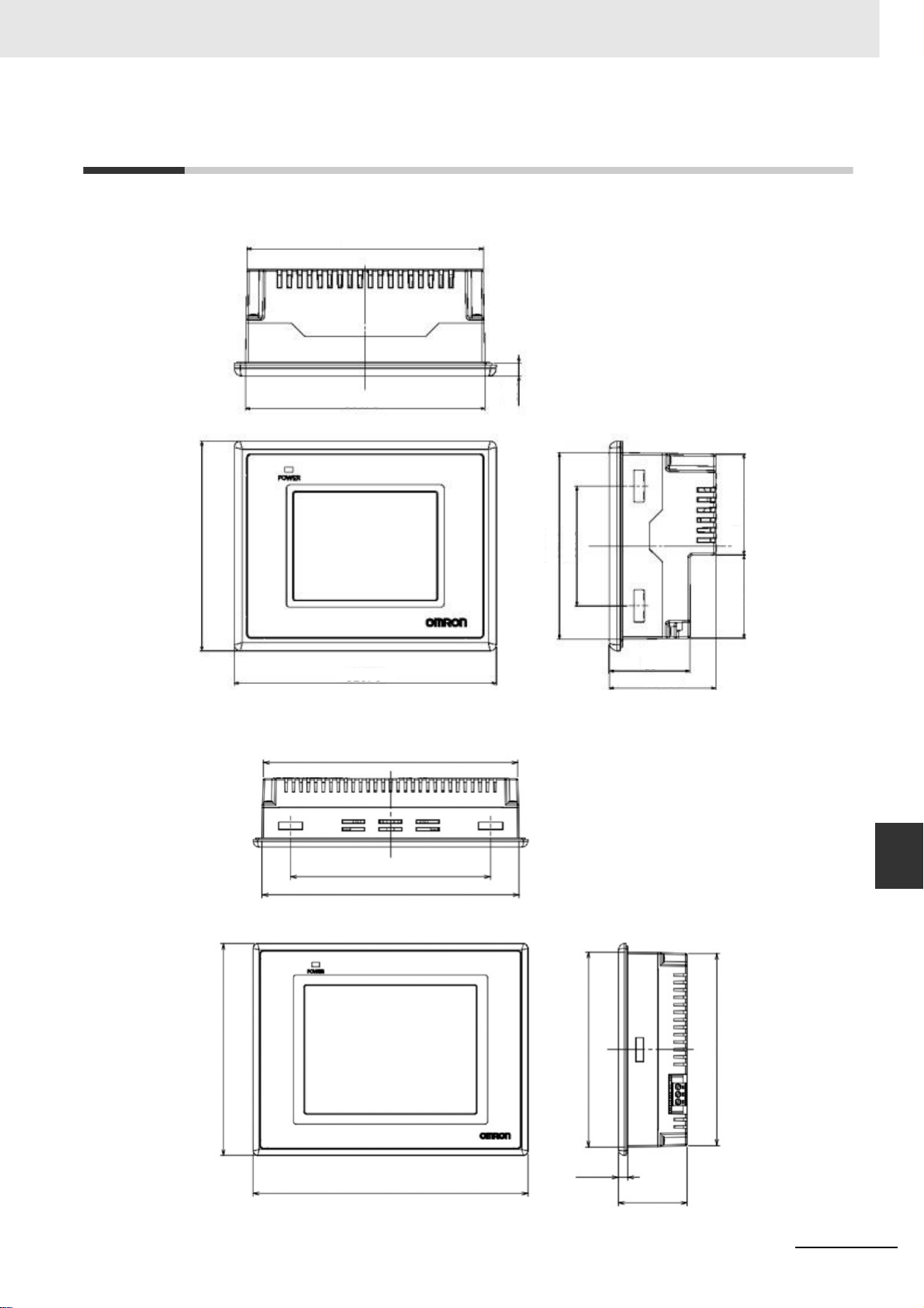
A-2 External Dimensions
NB3Q-TW00B/NB3Q-TW01B model
116.9
Appendices
118.5
103.8
129.8
NB5Q-TW00B/NB5Q-TW01B model
170.4
6.5
92.5
59.4
40
49.9
41.2
A-2 External Dimensions
52.8
App
134
172.2
142
184
NB-series Programmable Terminals Setup Manual(V107)
WWW.NNC.IR
130.8
6.2
A-1-3 Communication Specifications
129
46
A-5
Page 85

Appendices
NB7W-TW00B/NB7W-TW01B model
189
144
190.8
148
NB10W-TW01B model
254.7
200
257.1
202
136.8
6.2
135
46
A-6
210.8
268.8
WWW.NNC.IR
116
199.1
6.2
54
NB-series Programmable Terminals Setup Manual(V107)
196.7
Page 86
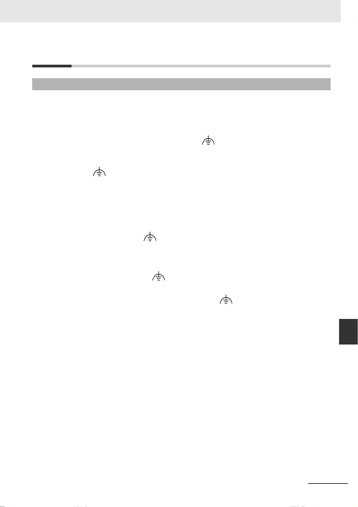
A-3 RS-422A/485 Connections
A-3-1 Grounding and Shielding of the Cables
When performing communications using RS-422A/485, carry out the connections, shielding and
grounding as follows:
Grounding wiring
The NB Unit has a functional grounding terminal (FG: ).
(1) Generally, make the grounding according to Fig. (a).
• Connect the grounding terminals (GR) of the devices and the functional grounding terminal
( ), at only one point make a D-type grounding (Max. grounding resistance 100Ω).
• Short-circuit the LG terminal and GR terminal of the PLC.
2
• Use a cable with a minimum of 2 mm
• For details about the connection methods, refer to the related communication Unit
manuals.
(2) As shown in Fig. (b), when the NB Unit, and noise source equipments such as motors and
inverters, etc. are installed on the same panel, do not ground the NB Unit’s functional
for the grounding cable.
Appendices
grounding terminal ( ).
Shielding of RS-422A/485 Cables
Be sure to shield the RS-422A/485 cables. Connect the grounding terminals (GR) of the devices and
the functional grounding terminals ( ), at only one point make a D-type grounding (Max. grounding
resistance 100Ω), carry out a single-end shielding according to Fig. (a).
If grounding is not done to the functional grounding terminal ( ) of the NB Unit, shield both ends as
shown in Fig. (b).
Note In order to avoid malfunctions caused by interferences, shield the cables properly.
A-3 RS-422A/485 Connections
App
A-3-1 Grounding and Shielding of the Cables
NB-series Programmable Terminals Setup Manual(V107)
A-7
WWW.NNC.IR
Page 87

Appendices
Figure(b)Figure(a)
CPU Rack
CPU Unit or
Communication Unit
RS-422A/485
Signal line
Power
supply
Unit
LG
GR
FG
FG
CPU Rack
CPU Unit or
Communication Unit
PT
RS-422A/485
Signal line
PT
Power
supply
Unit
LG
GR
PT
FG
PT
FG
FG
PT
PT
FG
A-8
NB-series Programmable Terminals Setup Manual(V107)
WWW.NNC.IR
Page 88

Appendices
A-4 Fabrication of the Connection Cable
Fabricate the connection cable following the procedures below.
A-4-1 Cable Processing
1
Cut the cable to the required length.
2
Use a tool like a razor, etc. to cut off the ethylene peel of the cable. Be care not to damage the
shielding layer (for grouping purpose)
3
Use a pair of scissors to snip off the shielding layer.
4
Bring out the core of each wire using a wire stripper.
5
Fold back the shielding layer.
6
Wrap the folded part of the shielding layer with aluminum foil tape.
40 (RS-232C)
25 (RS-422A/RS485)
10
5
A-4 Fabrication of the Connection Cable
App
A-4-1 Cable Processing
(Unit mm)
NB-series Programmable Terminals Setup Manual(V107)
Aluminum foil tape
A-9
WWW.NNC.IR
Page 89

Appendices
A-4-2 Soldering
1
Sheathe each wire with a heat shrinkable tube.
2
Place some standby soldering tin on each wire and each pin of the connector.
3
Solder each wire and each pin of the connector.
1mm
Soldering
iron
Heat-shrinkable tube
Inside diameter:1.5
Length=10
4
Pull the heat shrinkable tubes back to the soldering parts, heat them with a heat shrinking gun
to make them shrink.
A-4-3 Shield Assembly
Assemble the connector shield as shown below.
Heat-shrinkable tube
A-10
The end connected
to the connector
Aluminum
Foil Tape
WWW.NNC.IR
The end not connected
to the connector
NB-series Programmable Terminals Setup Manual(V107)
Page 90

Appendices
.
A-4-4 Method for Fabricating the Cable for Connection to OMRON PLC
When fabricating the cable for connecting the NB Unit and OMRON PLC, refer to the following
methods:
COM1
The cable for connecting the NB3Q Unit serial port COM1 to OMRON PLC
(RS-232C)
COM1 (female)
at the NB Unit side
1
5
6
9
NB Unit side
Signal Name Pin No.
FG
SDB+ 1
SD(TXD)
RD(RXD)
RS(RTS)
CS(CTS)
RDB+
SDA-
RDA-
SG
Connector
Shield
2
3
4
5
6
7
8
9
Shielded Cable
OMRON PLC side
Pin No.
Signal Name
1
2
3
4
5
6
7
8
9
FG
SD
RD
RS
CS
5V
NC
NC
SG
The cable for connecting the NB3Q Unit serial port COM1 to OMRON PLC
(RS-422A)
RS232 port at the
OMRON PLC side
(female)
1
5
6
9
A-4 Fabrication of the Connection Cable
COM1 (female)
at the NB Unit side
1
5
6
9
NB Unit side
Signal Name Pin No.
SDB+
SD(TXD)
RD(RXD)
RS(RTS)
CS(CTS)
RDB+
SDARDA-
SG
FG
Connector
Shield
1
2
3
4
5
6
7
8
9
Shielded Cable
OMRON PLC side
Pin No.
Signal Name
1RDA2
3
4
5
RDB+
SDA-
SDB+
FG
Note If the RS-485 connection is adopted, all needed to do is to connect the No.6 and No.8 pins and the shielded
cable to the corresponding pins on the PLC side.
The cable for connecting the NB5Q/NB7W/NB10W Unit serial port COM1 to
OMRON PLC (RS-232C)
COM1 (female)
at the NB Unit side
1
5
6
9
NB Unit side
Signal Name Pin No.
FG
NC 1
SD
RD
RS(RTS)
CS(CTS)
DC+5V
NC
NC
SG
Connector
Shield
2
3
4
5
6
7
8
9
Shielded Cable
OMRON PLC side
Pin No.
Signal Name
1
2
3
4
5
6
7
8
9
FG
SD
RD
RS
CS
5V
DR
ER
SG
RS232 port at the
OMRON PLC side
(female)
1
5
6
9
App
A-4-4 Method for Fabricating the Cable for
Connection to OMRON PLC
NB-series Programmable Terminals Setup Manual(V107)
A-11
WWW.NNC.IR
Page 91

Appendices
COM2
The cable for connecting the NB5Q/NB7W/NB10W Unit serial port COM2 to
OMRON PLC (RS-232C)
COM2 (female)
at the NB Unit side
1
5
6
9
NB Unit side
Signal Name Pin No.
FG
SDB+ 1
SD(TXD)
RD(RXD)
Terminal 1
Terminal 2
RDB+
SDARDA-
SG
Connector
Shield
2
3
4
5
6
7
8
9
Shielded Cable
OMRON PLC side
Pin No.
Signal Name
1
2
3
4
5
6
7
8
9
FG
SD
RD
RS
CS
5V
DR
ER
SG
RS232 port at the
OMRON PLC side
(female)
1
5
6
9
The cable for connecting the NB5Q/NB7W/NB10W Unit serial port COM2 to
OMRON PLC (RS-422A)
COM2 (female)
at the NB Unit side
1
5
6
9
NB Unit side
Signal Name Pin No.
SDB+
SD(TXD)
RD(RXD)
Terminal 1
Terminal 2
RDB+
SDARDA-
SG
FG
1
2
3
4
5
6
7
8
9
Connector
Shield
Shielded Cable
OMRON PLC side
Pin No.
Signal Name
1RDA2
3
4
5
RDB+
SDA-
SDB+
FG
Note If the RS-485 connection is adopted, all needed to do is to connect the No.6 and No.8 pins and the shielded
cable to the corresponding pins on the PLC side.
A-12
NB-series Programmable Terminals Setup Manual(V107)
WWW.NNC.IR
Page 92

A-4-5 Method for fabricating the cable for connection to PC
When fabricating the cable for connecting with NB-Designer, refer to the following methods:
Depending on the type of the RS-232C connector compatible with PCs according to DOS/V, deploy the
wiring as shown below:
25-pin Connector
Appendices
COM1 (female)
at the NB Unit side
1
5
NB Unit side
Signal Name Signal Name
6
9
FG
NC
SD
RD
RS (RTS)
CS (CTS)
DC+5V
NC
NC
SG
9-pin Connector
COM1 (female)
at the NB Unit side
1
5
NB Unit side
Signal Name Signal Name
6
9
FG
NC
SD
RD
RS (RTS)
CS (CTS)
DC+5V
NC
NC
SG
DB25 Serial Port at the PC side
Pin No. Pin No.
Connector
Shield
1
2
3
4
5
6
7
8
9
Pin No. Pin No.
Connector
Shield
1
2
3
4
5
6
7
8
9
Shielded Cable
Connector
Shield
DB9 Serial Port at the PC side
Shielded Cable
Connector
Shield
20
22
RS232 DB25 (male)
at the PC side
FG
1
2
3
4
5
6
7
8
1
2
3
4
5
6
7
8
9
FG
SD
RD
RS
CS
DR
SG
CD
ER
RI
FG
CD
RD
SD
ER
SG
DR
RS
CS
RI
13
25
14
1
RS232 DB9 (male)
at the PC side
5
1
A-4 Fabrication of the Connection Cable
9
App
A-4-5 Method for fabricating the cable for
6
connection to PC
Note As to the 2 connection methods introduced above, the No.2, 3 and 9 pins of COM1 on the NB3Q unit side
have the same definitions as those described in the above diagram, and the method for connection to a PC
is also the same as above.
NB-series Programmable Terminals Setup Manual(V107)
A-13
WWW.NNC.IR
Page 93

Appendices
A-5 List of Models
NB Unit
Models Resolution Size Communication
NB3Q-TW00B QVGA 320✕ 240 3.5 inches COM1 Slave
NB3Q-TW01B QVGA 320✕ 240 3.5 inches COM1, Ethernet Host, Slave
NB5Q-TW00B QVGA 320✕ 234 5.6 inches COM1, COM2 Slave
NB5Q-TW01B QVGA 320✕ 234 5.6 inches COM1, COM2, Ethernet Host, Slave
NB7W-TW00B WVGA 800✕ 480 7 inches COM1, COM2 Slave
NB7W-TW01B WVGA 800✕ 480 7 inches COM1, COM2, Ethernet Host, Slave
NB10W-TW01B WVGA 800✕ 480 10.1 inches COM1, COM2, Ethernet Host, Slave
Serial Communication Unit
USB
(Equivalent of USB 2.0
Full Speed)
Models Specifications Applicable PLCs
CS1W-SCU21 • RS-232C (2 ports) CS series CS1G/H, CS1G/H-H
CS1W-SCU31 • RS-422A/485 (2 ports) CS series CS1G/H, CS1G/H-H
CJ1W-SCU21 • RS-232C (2 ports) CJ1 series CJ1G/H-H, CJ1M
CJ1W-SCU31 • RS-422A (2 ports) CJ1 series CJ1G/H-H, CJ1M
CJ1W-SCU41 • RS-232C (1 port)
• RS-422A (1 port)
CJ1 series CJ1G/H-H, CJ1M
Ethernet Communication Unit
Models Specifications Applicable PLCs
CS1W-ETN21 • 100Base-TX, 10Base-T CS series CS1G/H, CS1G/H-H
CS1W-EIP21 • 100Base-TX, 10Base-T CS series CS1G/H, CS1G/H-H
CJ1W-ETN21 • 100Base-TX, 10Base-T CJ1 series CJ1G/H-H, CJ1M
CJ1W-EIP21 • 100Base-TX, 10Base-T CJ1 series CJ1G/H-H, CJ1M
CJ1W-CIF41 • 100Base-TX, 10Base-T CP1H, CP1L, CP1E
A-14
NB-series Programmable Terminals Setup Manual(V107)
WWW.NNC.IR
Page 94

Appendices
PLC Series Connectable to NB Series through Host Link
PLC Series Specifications
CP Series Connecting through the RS-232C optional communication board
(CP1W-CIF01) with a RS-232C cable
C200HE/HG/HX Series With a connector for RS-232C connection (switch/9-pin type)
CQM1H Series With a connector for RS-232C connection (9-pin type)
CPM1A Series Connecting through the RS-232C adaptor (CP1W-CIF01) with a RS-232C
cable
CPM2A Series With a connector for RS-232C connection (9-pin type)
CPM2C Series Connect to the branched RS-232C connector through a conversion cable
(CPM2C-CN111 type)
CS Series With a connector for RS-232C connection (9-pin type)
CJ1/CJ2 Series With a connector for RS-232C connection (9-pin type)
PLC Series connectable to NB Series through the Ethernet Unit
PLC Series Specifications
CP Series Connecting through the Ethernet optional communication board CJ1W-CIF41
CS Series Connecting through the Ethernet Unit CS1W-ETN21 or CS1W-EIP21
CJ1 Series Connecting through the Ethernet Unit CJ1W-ETN21 or CJ1W-EIP21
CJ2 Series Connecting through the Ethernet Unit CJ1W-ETN21 or CJ1W-EIP21
A-5 List of Models
App
A-4-5 Method for fabricating the cable for
connection to PC
NB-series Programmable Terminals Setup Manual(V107)
A-15
WWW.NNC.IR
Page 95

Appendices
Units at the host side which can be connected using the serial port of the NB
Unit in the RS-232C mode through Host Link
PLC
Series
CP Series CP1L-L14/L20/M30/M40/M60 CP1W-CIF01
C Series C200HE-CPU11/32/42
CS Series CS1G-CPU42/43/44/45(-V1)
CJ1
Series
CJ2
Series
CPU Unit with built-in Host
Link function
CP1E-N14/N20
CP1E-N30/N40/N60/NA20 CP1E-N30/N40/N60/NA20 CP1W-CIF01
C200HE-CPU42
C200HE-CPU42-Z
C200HG-CPU43/63
C200HG-CPU43/63-Z
C200HX-CPU44/64
C200HX-CPU44/64/65/85-Z
CPM1-10/20CDR-
+CPM1-CIF01
CPM1A-10/20/30/40CD-
+CPM1-CIF01
CPM2A-30/40/60CD-
+CPM1-CIF01
(When a peripheral port is
connected)
CPM2C-10/20-
(*1)
CQM1H-CPU11/21/51/61 (*2) CQM1H-CPU51/61 CQM1H-SCB41
CS1H-CPU63/64/65/66/67(-V1)
CS1G-CPU42H/43H/44H/45H
CS1HCPU63H/64H/65H/66H/67H
CJ1G-CPU44/CPU45 CJ1G-CPU44/CPU45 CJ1W-SCU21/41/-V1
CJ1G-CPU42H/43H/44H/45H
CJ1H-CPU65H/66H/67H
CJ1M-CPU11/12/13/21/22/23 CJ1M-CPU11/12/13/21/22/23 CJ1W-SCU21/41/-V1
CJ2M-CPU31/32/33/34/35 CP1W-CIF01
CJ2M-CPU11/12/13/14/15
CJ2H-CPU64/65/66/67/68(-EIP)
CPU Unit that can be connected
through adding Host Link
Units/communication boards
CP1H-X40/XA40/Y20 CP1W-CIF01
CP1L-EL20/EM30/EM40 CP1W-CIF01
C200HE-CPU11/32/42-Z
C200HG-CPU33/43/53/63
C200HG-CPU33/43/53/63-Z
C200HX-CPU34/44/54/64
C200HX-CPU34/44/54/64/65/85-Z
C200HE-CPU32/42
C200HE-CPU32/42-Z
C200HG-CPU33/43/53/63
C200HG-CPU33/43/53/63-Z
C200HX-CPU34/44/54/64
C200HX-CPU34/44/54/64/65/85-Z
CS1G-CPU42/43/44/45(-V1)
CS1H-CPU63/64/65/66/67(-V1)
CS1G-CPU42H/43H/44H/45H
CS1H-CPU63H/64H/65H/66H/67H
CJ1G-CPU42H/43H/44H/45H
CJ1H-CPU65H/66H/67H
Options required for
connection
C200H-LK201-V1
C200HWCOM02/04/05/06-V1
C200HWCOM02/04/05/06-V1
C200HWCOM02/04/05/06-V1
CS1W-SCU21(-V1)
CS1W-SCB21/41(-V1)
CS1W-SCU21(-V1)
CS1W-SCB21/41(-V1)
CJ1W-SCU21/41/-V1
A-16
*1: Connect using conversion cables (CPM2C-CN111 type or CS1W-CN114/118 type), the RS-232C adaptor
(CPM1-CIF01 type) or the RS-422A adaptor (CPM1-CIF11 type).
*2: The CQM1H-CPU11 model does not have the RS-232C port built in the CPU, therefore it requires a peripheral
port to be connected to a PT through a conversion cable (CS1W-CN118 type).
NB-series Programmable Terminals Setup Manual(V107)
WWW.NNC.IR
Page 96

Appendices
Units at the host side which can be connected using the serial port of the NB
Unit in the RS-422A mode through Host Link
PLC Series
CP Series CP1L-L14/L20/M30/M40/M60 CP1L-L14/L20/M30/M40/M60 CP1W-CIF11/CIF12
C Series C200HE-CPU11/32/42
CS Series CS1G-CPU42/43/44/45(-V1)
CJ1 Series CJ1G-CPU44/45 CJ1W-SCU31/41-V1
CJ2 Series CJ2M-CPU31/32/33/34/35 CP1W-CIF11/CIF12
CPU Unit with built-in Host
Link function
CP1H-X40/XA40/Y20 CP1H-X40/XA40/Y20 CP1W-CIF11/CIF12
CP1E-N30/N40/N60/NA20 CP1E-N30/N40/N60/NA20 CP1W-CIF11/CIF12
CPM1-10/20CDR-
+CPM1-CIF11
CPM1A-10/20/30/40CD-
+CPM1-CIF11
CPM2A-30/40/60CD-
+CPM1-CIF11
(When a peripheral port is connected)
CPM2C-10/20-
(*1)
CJ2M-CPU11/12/13/14/15
CJ2H-CPU64/65/66/67/68
(-EIP)
CPU Unit that can be connected
through adding Host Link
Units/communication boards
CP1L-EL20/EM30/EM40 CP1W-CIF11/CIF12
C200HE-CPU11/32/42-Z
C200HG-CPU33/43/53/63
C200HG-CPU33/43/53/63-Z
C200HX-CPU34/44/54/64
C200HX-CPU34/44/54/64/65/85-Z
C200HE-CPU32/42
C200HE-CPU32/42-Z
C200HG-CPU33/43/53/63
C200HG-CPU33/43/53/63-Z
C200HX-CPU34/44/54/64
C200HX-CPU34/44/54/64/65/85-Z
CQM1H-CPU51/61 CQM1H-SCB41
CS1H-CPU63/64/65/66/67(-V1)
CS1G-CPU42H/43H/44H/45H
CS1H-CPU63H/64H/65H/66H/67H
CJ1G-CPU42H/43H/44H/45H
CJ1H-CPU65H/66H/67H
CJ1M-CPU11/12/13/21/22/23 CJ1W-SCU31/41-V1
Options required for
connection
C200H-LK202-V1
C200HW-COM03/06-V1
C200HW-COM03/06-V1
C200HW-COM03/06-V1
CS1W-SCB41(-V1)
CS1W-SCU31(-V1)
CS1W-SCB41(-V1)
CS1W-SCU31(-V1)
CJ1W-SCU31/41-V1
connection to PC
A-5 List of Models
App
A-4-5 Method for fabricating the cable for
*1: Connect using conversion cables (CPM2C-CN111 type or CS1W-CN114/118 type), the RS-232C adaptor
(CPM1-CIF01 type) or the RS-422A adaptor (CPM1-CIF11 type).
NB-series Programmable Terminals Setup Manual(V107)
A-17
WWW.NNC.IR
Page 97

Appendices
Units at the host side which can be connected using the Ethernet port of the
NB Unit
PLC Series
CP Series CP1L-L14/L20/M30/M40/M60 CP1W-CIF41
CS Series CS1G-CPU42/43/44/45(-V1)
CJ1 Series CJ1G-CPU42H/43H/44H/45H
CJ2 Series CJ2M-CPU31/32/33/34/35
CPU Unit with built-in Ethernet
communication function
CP1L-EL20/EM30/EM40
CJ2H-CPU64/65/66/67/68(-EIP)
CPU Unit that can be connected through
adding Ethernet Communication
Unit/optional communication board
CP1H-X40/XA40/Y20 CP1W-CIF41
CP1E-N30/N40/N60/NA20 CP1W-CIF41
CS1H-CPU63/64/65/66/67(-V1)
CS1G-CPU42H/43H/44H/45H
CS1H-CPU63H/64H/65H/66H/67H
CS1H-CPU63/64/65/66/67(-V1) CS1W-ETN21
CS1H-CPU63H/64H/65H/66H/67H CS1W-ETN21
CJ1H-CPU65H/CPU66H
CJ1M-CPU11/12/13/21/22/23 CJ1W-ETN21
CJ1H-CPU65H-R/66H-R/67H-R
CJ1H-CPU65H/CPU66H
CJ2M-CPU11/12/13/14/15 CJ1W-ETN21
Options
required for
connection
CS1W-ETN21
CS1W-EIP21
CS1W-ETN21
CS1W-EIP21
CS1W-EIP21
CS1W-EIP21
CJ1W-ETN21
CJ1W-EIP21
CJ1W-EIP21
CJ1W-ETN21
CJ1W-EIP21
CJ1W-EIP21
Software related to the NB Unit
Name Version Release Time Descriptions Remarks
NB-Designer V1.0X February 2012 HMI with model number
of NB5Q-TW00B and
NB7W-TW00B supported
V1.1X June 2012 HMI with model number
of NB5Q-TW01B and
NB7W-TW01B added
V1.2X August 2012 HMI with model number
of NB3Q-TW00B/TW01B
and NB10W-TW01B
added
OS: Windows XP (SP1 or higher)
Windows Vista/Windows 7 (32/64-bit)
The NB-Designer incorporates a
transmission program and a standard
system program specified for the NBSeries Units. For download the
application programs, please access
your local Omron website, If local site
cannot be found, please access Omron
IA global site “http://www.ia.omron.com/ ”
at first and select the area where you
are.
Related connecting objects
Cable with connectors (NB Unit ↔ PLC)
Models Cable Length Object Unit Communications methods Specifications
XW2Z-200T 2m Units with 9-pin
XW2Z-500T 5m
NB-RSEXT-2M 2m RS-422/485
connectors by
OMRON
Communication
Units by PLC
manufacturers
Host Link
(RS-232C)
Host Link
(RS-422/485)
9-pin ↔9-pin
9-pin ↔5-wire
A-18
NB-series Programmable Terminals Setup Manual(V107)
WWW.NNC.IR
Page 98

A-6 List of Options
Anti-reflection Film
It adheres to the display preventing reflection and also dirt from sticking to the display. It is colorless
and transparent, with 1 set containing 5 pieces.
NB Unit Models Models Specifications
NB3Q-TWB NB3Q-KBA04 5 pieces
NB5Q-TWB NB5Q-KBA04
NB7W-TWB NB7W-KBA04
NB10W-TW01B NB10W-KBA04
Installation fittings
Models Descriptions
NB5Q-ATT01 When HMI users switch from the NT31/C or NQ5 Series to HMI of NB5Q
Series, due to the difference of the unit size, installation fittings can be
utilized to guarantee the process quick and smooth.
NB10W-ATT01 When HMI users switch from the NB10W-TW00B-Z Series to HMI of
NB10W-TW01B Series, due to the difference of the unit size, installation
fittings can be utilized to guarantee the process quick and smooth.
Appendices
A-6 List of Options
App
A-4-5 Method for fabricating the cable for
connection to PC
NB-series Programmable Terminals Setup Manual(V107)
A-19
WWW.NNC.IR
Page 99

Appendices
RS-422A/RS-485 Communication Cable
NB-RSEXT-2M Only applies to the COM2 port of the NB series product, when
Models Descriptions
performing communications using RS-422A/RS485, can be equipped
with this communication cable.
Signal
SDB+
SD
RD
RS
CS
RDB+
SDARDA-
SG
FG
NB Model
NB5Q /NB7W/
NB10W-TWB
Terminal R1
Terminal R2
NB
Serial Port
D-Sub
9Pin
(Female)
signal wire
shield wire
Pin NO.
1
2
3
4
5
6
7
8
9
Shell
NB3Q-TWB
Conform to UL2464, AWG28
Instruction: When users need to carry out long-distance signal
transmission, can connect with terminal matching resistance.
How to use:
When using NB5Q/NB7W/NB10W-TWB Unit, open RS-422A/
RS-485 communication cable RS232C Connector, use short wire to
connect PIN4 and PIN5, pay attention to wiring, do not short-circuit
with other pins except PIN4 and PIN5, when connection finished
please assembled well RS232C Connector.
When using NB3Q-TW
B Unit, turn the DIP switch SW3 of the unit
to ON.
By default, RS-422A/RS-485 communication cable do not connect
terminal resistance.
Signal
SDB+
SD
RD
RDB+
SDARDA-
SG
FG
Red
White
Blue
Brown
Black
USB Memory
It can be connected to the USB HOST port on the back of PT to perform the uploading,
downloading, project operation and storage of related data.
Recommended Purchasing Model Descriptions
FZ-MEM2G USB disk with 2GB capacity manufactured by OMRON
FZ-MEM8G USB disk with 8GB capacity manufactured by OMRON
A-20
NB-series Programmable Terminals Setup Manual(V107)
WWW.NNC.IR
Page 100

Revision History
A manual revision code appears as a suffix to the Catalog number on the front cover of the manual.
Revision code Date Revised content
01 October 2011 Original production
02 February 2012 • Adding optional RS-422A / RS485 communication cable
03 April 2012 Adding descriptions and new functions of NB5Q/NB7W-
04 August 2012 Adding descriptions and new functions of NB3Q-
Cat. No. V107-E1-
Revision code
in Appendix-6.
• Correcting the descriptions of the battery.
TW01B model.
TW00B/TW01B and NB10W-TW01B models.
NB-series Programmable Terminals Setup Manual(V107)
Revision-1
WWW.NNC.IR
 Loading...