

Page 1

At the end of this document you will find links to products related to this catalog. You can go directly to our shop by
clicking HERE. HERE
Page 2

ZX-T Series
Cat. No. V109-E2-04
Programmable Terminals
STARTUP GUIDE MANUAL
Cat. No. V109-E2-04 Programmable Terminals NB-series STARTUP GUIDE MANUAL
NB-series
NB3Q-TW_B
NB5Q-TW_B
NB7W-TW_B
NB10W-TW01B
Page 3

OMRON, 2012
All rights reserved. No part of this publication may be reproduced, stored in a retrieval system, or transmitted, in any form, or
by any means, mechanical, electronic, photocopying, recording, or otherwise, without the prior written permission of
OMRON.
No patent liability is assumed with respect to the use of the information contained herein. Moreover, because OMRON is constantly striving to improve its high-quality products, the information contained in this manual is subject to change without
notice. Every precaution has been taken in the preparation of this manual. Nevertheless, OMRON assumes no responsibility
for errors or omissions. Neither is any liability assumed for damages resulting from the use of the information contained in
this publication.
Page 4

NB-series
NB3Q-TWB
NB5Q-TWB
NB7W-TWB
NB10W-TW01B
Programmable Terminals
Startup Guide Manual
Revised August 2012
Page 5

Page 6

1
NB-series Programmable Terminals Startup Guide Manual(V109)
Introduction
Thank you for purchasing an NB-series Programmable Terminal.
NB-Series Programmable Terminals (PTs) are designed to handle information generated in FA production
sites. Be sure to understand the functions and performances etc thoroughly before using PT correctly.
This manual is intended for the following personnel, who must also have knowledge of electrical
systems (an electrical engineer or the equivalent).
• Personnel in charge of introducing FA systems into production facilities.
• Personnel in charge of designing FA systems.
• Personnel in charge of installing and connecting FA facilities.
• Personnel in charge of managing FA systems and facilities
• The user must operate the product according to the performance specifications described in the
operation manuals.
• Do not use the PT touch switch input functions for applications where danger to human life or serious
property damage is possible, or for emergency switch applications.
• Before using the product under conditions which are not described in the manual or applying the
product to nuclear control systems, railroad systems, aviation systems, vehicles, combustion
systems, medical equipment, amusement machines, safety equipment, and other systems,
machines and equipment that may have a serious influence on lives and property if used improperly,
consult your OMRON representative.
• Make sure that the ratings and performance characteristics of the product are sufficient for the
systems, machines, and equipment, and be sure to provide the systems, machines, and equipment
with double safety mechanisms.
• This manual provides information for connecting and setting up an NB-Series PT. Be sure to read
this manual before attempting to use the PT and keep this manual close at hand for reference during
installation and operation.
Intended Audience
General Precautions
Page 7
2
NB-series Programmable Terminals Startup Guide Manual(V109)
NB-series Manuals
NB-series manuals are organized in the sections listed in the following tables. Refer to the appropriate
section in the manuals as required.
Programmable Terminals Startup Guide Manual (Cat. No. V109)
(This manual)
Section Contents
Section 1 NB Overview This section provide specifications of the NB Unit, describes its names
and functions of the various parts.
Section 2 System Design This section describes the manual structure, takes NB7W as an
example to introduce the operation procedures of the NB system.
Section 3 Installation and Wiring This section describes how to install and wire the NB Unit.
Section 4 Screen Creation This section describes how to create a demonstration project through
NB-Designer.
Section 5 Run This section describes how to start running at the Host side and
prepare to send screen data to NB7W.
Section 6 Maintenance and
Troubleshooting
This section describes the maintenance and inspection methods for
preventing errors occurring, and troubleshooting measures when errors
occur.
Programmable Terminals NB-Designer Operation Manual
(Cat. No. V106)
Section Contents
Section 1 Introduction This section provides an outline of the NB-series PTs, including their
functions, features, connection types and communication methods.
Section 2 Installation and Startup of
NB-Designer
This section describes how to install and start the NB-Designer.
Section 3 Functions of NB-Designer This section describes the functions of NB-Designer.
Section 4 Functions of NBManager This section describes the functions of NBManager.
Section 5 Maintenance and
Abnormality Handling
This section describes the maintenance and check to prevent the
abnormality occurrence and the handling of the abnormalities occurred
in NB Unit.
Section 6 Descriptions of New
Functions Added into NBTW01B
This section describes the new functions added into NB-TW01B,
the system attributes and the component attributes.
Appendices The appendices provide lists of the NB Units, the Communication Units,
the applicable PLCs, and the list of NB-Designer functions.
Page 8
3
NB-series Programmable Terminals Startup Guide Manual(V109)
Programmable Terminals Setup Manual (Cat. No. V107)
Section Contents
Section 1 Part Names and Functions This section describes the names and functions of the various parts of
an NB Unit.
Section 2 Installing the NB Unit and
Connecting Peripheral Devices
This section describes the methods used to install the NB Unit and
connect peripheral devices.
Section 3 System Setting Mode This section describes the System Setting Mode.
Section 4 Calibrate Mode This section describes the Calibrate Mode.
Appendices The appendices provide information on specifications, dimensions,
wirings, and lists of the NB Units, the applicable PLCs and options.
Programmable Terminals Host Connection Manual (Cat. No. V108)
Section Contents
Section 1 List for All PLCs
Supported by NB series
This section lists all PLCs supported by NB Units.
Section 2 Connecting to SIEMENS
PLCs
This section describes the connection to SIEMENS PLCs.
Section 3 Connecting to Mitsubishi
PLCs
This section describes the connection to Mitsubishi PLCs.
Section 4 Connecting to Schneider
PLCs
This section describes the connection to Schneider PLCs.
Section 5 Modbus Connection This section describes the connection on Modbus protocol.
Section 6 Connecting to Delta PLCs This section describes the connection to Delta PLCs.
Section 7 Connecting to LG PLCs This section describes the connection to LG PLCs.
Section 8 Connecting to Panasonic
PLCs
This section describes the connection to Panasonic PLCs.
Section 9 Connecting to AllenBradley (Rockwell) PLC
This section describes the connection to Allen-Bradley PLC.
Section 10 Connecting to PLC of GE
Fanuc Automation Inc.
This section describes the connection to PLC of GE Fanuc Automation
Inc.
WARNING
Failure to read and understand the information
provided in this manual may result in personal injury
or death, damage to the product, or product failure.
Please read each section in its entirety and be sure
you understand the information provided in the
section and related sections before attempting any
of the procedures or operations given.
Page 9
4
NB-series Programmable Terminals Startup Guide Manual(V109)
Manual Structure
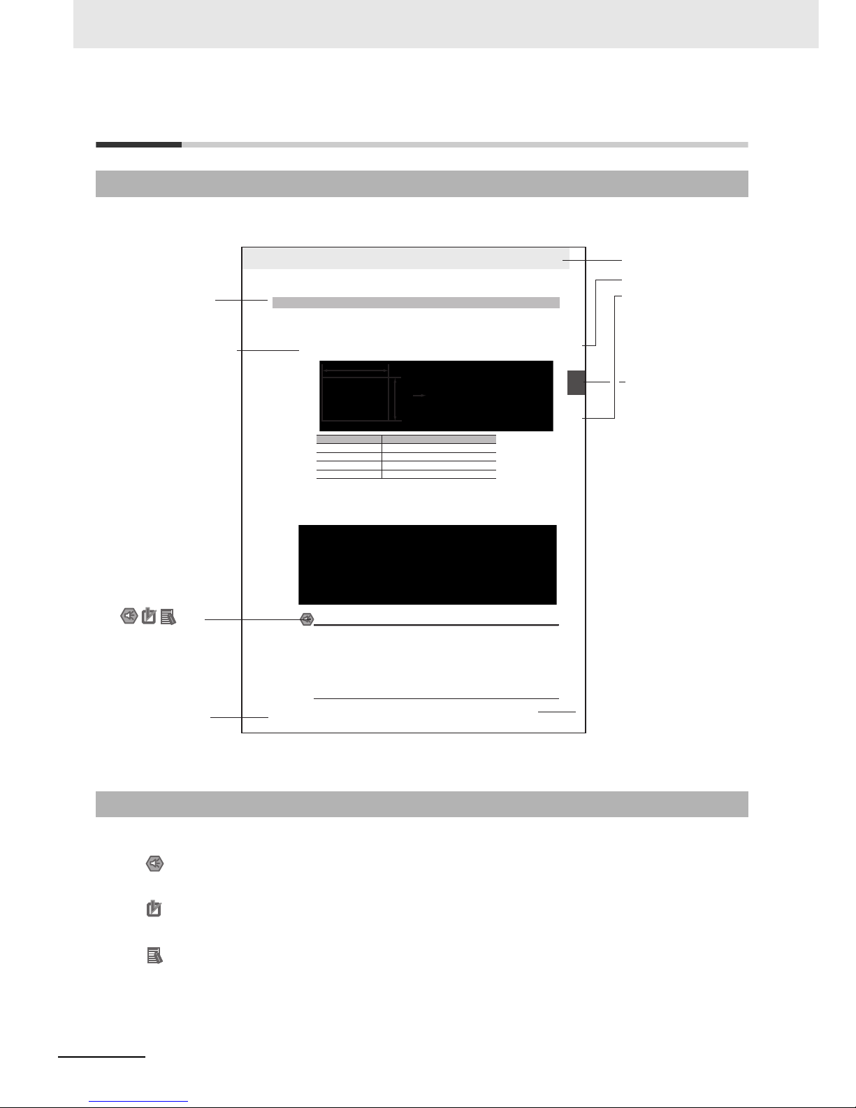
The following page structure and icons are used in this manual.
Special information in this manual is classified as follows:
Page Structure and Icons
Special Information
2-3
2 Installing the NB Unit and Connecting Peripheral Devices
NB-series Programmable Terminals Setup Manual(V107)
2-1 Installing the NB Unit
2
2-1-2 Installation onto the Operation Panel
Install the NB Unit by embedding it into the operation panel.
Use the metal kit and tool (a crosshead screwdriver) supplied with the Unit for installation.
Proceed the installation following the procedures below.
1
Panel cutout with dimensions is shown below. Fit the NB Unit into the panel from the front side.
2
As follows, insert panel fixators at the locations indicated by red box around the back of the NB Unit.
Insert the hooks of positioners into the square holes on the Unit to hold the fixators properly, and
tighten the screws firmly with the screwdriver.
NB5Q/NB7W-TWB
Precautions for Safe Use
• When operating on the operation panel, make sure to keep metal particles from entering the
Unit.
The mounting panel must be between 1.6 and 4.8 mm thick. The NB Unit must be installed
in a control panel.
For the sake of waterproof and dustproof, all the fixators must be evenly tightened to a
torque of 0.5~0.6 Nm. If the tightening torque exceeds the specified value, or the tightening
is not even, deformation of the front panel may occur.
Make sure that the operation panel is clean, unbent, and strong enough for the installation
process.
2-1-2 Installation onto the Operation Panel
Models Opening Dimension (W H mm)
NB3Q-TW00B/TW01B 119.0(+0.5/-0) 93.0(+0.5/-0)
NB5Q-TW00B/TW01B 172.4(+0.5/-0) 131.0(+0.5/-0)
NB7W-TW00B/TW01B 191.0(+0.5/-0) 137.0(+0.5/-0)
NB10W-TW01B 258.0(+0.5/-0) 200.0(+0.5/-0)
Opening dimensions
Width
Height
Level 1 heading
Level 2 heading
Level 3 heading
Step in a procedure
Manual name
Special Information
(See below.)
Level 3 heading
Page tab
Gives the current
headings.
Indicates a step in a
procedure.
Gives the number
of the section.
This illustration is provided only as a sample and may not literally appear in this manual.
Icons are used to indicate
precautions and
additional information.
Precautions for Safe Use
Precautions on what to do and what not to do to ensure using the product safely.
Precautions for Correct Use
Precautions on what to do and what not to do to ensure proper operation and performance.
Additional Information
Additional information to increase understanding or make operation easier.
Page 10

5
NB-series Programmable Terminals Startup Guide Manual(V109)
Terminology
The following terminology is used in this manual.
Ter ms Descriptions
NB Unit Indicates the main Unit of the products in the OMRON NB Series of Programmable
Te r mi n a l .
NB Series Indicates products in the OMRON NB Series of Programmable Terminal.
In this manual, unless otherwise specified, NB Series is taken as the subject
concerned.
PLC Indicates a Programmable Controller.
CP Series Indicates the following products in the OMRON CP Series of Programmable Controllers:
CP1H, CP1L, CP1E
CS/CJ Series Indicates the following products in the OMRON CS/CJ Series of Programmable
Controllers: CS1G, CS1H, CS1G-H, CS1H-H, CJ1G, CJ1M, CJ2M, CJ2H
C Series Indicates the following products in the OMRON C Series of Programmable Controllers:
C200HX(-Z), C200HG(-Z), C200HE(-Z), CQM1, CQM1H, CPM1A, CPM2A, CPM2C
Serial Communication
Unit
Indicates a Serial Communication Unit for an OMRON SYSMAC CS/CJ-Series PLC.
Serial Communication
Board
Indicates a Serial Communication Board for an OMRON SYSMAC CS/CJ-Series PLC.
Communication Board Indicates a Communication Board for an OMRON C200HX/HG/HE(-Z) PLC.
CPU Unit Indicates a CPU Unit in the OMRON CP, CS/CJ or SYSMAC C Series of Programmable
Controllers.
NB-Designer Indicates the OMRON NB-Designer.
Host Indicates the PLC and other units functioning as the control devices for NB-Series
Units.
PT Indicates an OMRON Programmable Terminal.
HMI Indicates an OMRON Programmable Terminal.
Page 11

6
NB-series Programmable Terminals Startup Guide Manual(V109)
Page 12

7
NB-series Programmable Terminals Startup Guide Manual(V109)
CONTENTS
Introduction............................................................................................................... 1
NB-series Manuals.................................................................................................... 2
Manual Structure ...................................................................................................... 4
Terminology .............................................................................................................. 5
Safety Precautions ................................................................................................. 12
Precautions for Safe Use ....................................................................................... 14
Precautions for Correct Use .................................................................................. 16
Conformance to EC Directives .............................................................................. 17
Related Manuals ..................................................................................................... 18
Sec. 1 NB Overview........................................................................... 1-1
1-1 Models of NB Series................................................................................................................ 1-2
1-2 Part Names and Functions .....................................................................................................1-3
Sec. 2 System Design ....................................................................... 2-1
2-1 About this Manual ................................................................................................................... 2-2
2-2 Demonstration System ........................................................................................................... 2-3
Sec. 3 Installation and Wiring .......................................................... 3-1
3-1 Installation................................................................................................................................ 3-2
3-2 Equipment Wiring.................................................................................................................... 3-5
Sec. 4 Screen Creation ..................................................................... 4-1
4-1 Starting NB-Designer .............................................................................................................. 4-2
4-2 Main Window of NB-Designer................................................................................................. 4-3
4-3 Creating Project....................................................................................................................... 4-5
4-4 Screen Creation ..................................................................................................................... 4-13
4-5 HMI Attribute .......................................................................................................................... 4-27
4-6 Save and Load Project .......................................................................................................... 4-28
Page 13

8
NB-series Programmable Terminals Startup Guide Manual(V109)
Sec. 5 Run .......................................................................................... 5-1
5-1 Preparations............................................................................................................................. 5-2
5-2 Run NB7W ................................................................................................................................5-5
Sec. 6 Maintenance and Troubleshooting....................................... 6-1
6-1 Maintenance ............................................................................................................................. 6-2
6-2 Checking and Cleaning ........................................................................................................... 6-3
6-3 Troubleshooting....................................................................................................................... 6-5
6-4 Unit Replacement Precautions ............................................................................................. 6-34
Revision History........................................................................................................ 1
Page 14

9
NB-series Programmable Terminals Startup Guide Manual(V109)
Read and Understand this Manual
Please read and understand this manual before using the product. Please consult your OMRON representative
if you have any questions or comments.
Warranty and Limitations of Liability
WARRANTY
OMRON’s exclusive warranty is that the products are free from defects in materials and workmanship for a
period of one year (or other period if specified) from date of sale by OMRON.
OMRON MAKES NO WARRANTY OR REPRESENTATION, EXPRESS OR IMPLIED, REGARDING NONINFRINGEMENT, MERCHANTABILITY, OR FITNESS FOR PARTICULAR PURPOSE OF THE
PRODUCTS. ANY BUYER OR USER ACKNOWLEDGES THAT THE BUYER OR USER ALONE HAS
DETERMINED THAT THE PRODUCTS WILL SUITABLY MEET THE REQUIREMENTS OF THEIR
INTENDED USE. OMRON DISCLAIMS ALL OTHER WARRANTIES, EXPRESS OR IMPLIED.
LIMITATIONS OF LIABILITY
OMRON SHALL NOT BE RESPONSIBLE FOR SPECIAL, INDIRECT, OR CONSEQUENTIAL DAMAGES,
LOSS OF PROFITS OR COMMERCIAL LOSS IN ANY WAY CONNECTED WITH THE PRODUCTS,
WHETHER SUCH CLAIM IS BASED ON CONTRACT, WARRANTY, NEGLIGENCE, OR STRICT
LIABILITY.
In no event shall the responsibility of OMRON for any act exceed the individual price of the product on which
liability is asserted.
IN NO EVENT SHALL OMRON BE RESPONSIBLE FOR WARRANTY, REPAIR, OR OTHER CLAIMS
REGARDING THE PRODUCTS UNLESS OMRON’S ANALYSIS CONFIRMS THAT THE PRODUCTS
WERE PROPERLY HANDLED, STORED, INSTALLED, AND MAINTAINED AND NOT SUBJECT TO
CONTAMINATION, ABUSE, MISUSE, OR INAPPROPRIATE MODIFICATION OR REPAIR.
Page 15
10
NB-series Programmable Terminals Startup Guide Manual(V109)
Application Considerations
SUITABILITY FOR USE
OMRON shall not be responsible for conformity with any standards, codes, or regulations that apply to the
combination of products in the customer’s application or use of the products.
At the customer’s request, OMRON will provide applicable third party certification documents identifying
ratings and limitations of use that apply to the products. This information by itself is not sufficient for a
complete determination of the suitability of the products in combination with the end product, machine,
system, or other application or use.
The following are some examples of applications for which particular attention must be given. This is not
intended to be an exhaustive list of all possible uses of the products, nor is it intended to imply that the uses
listed may be suitable for the products:
• Outdoor use, uses involving potential chemical contamination or electrical interference, or conditions or
uses not described in this manual.
• Nuclear energy control systems, combustion systems, railroad systems, aviation systems, medical
equipment, amusement machines, vehicles, safety equipment, and installations subject to separate
industry or government regulations.
• Systems, machines, and equipment that could present a risk to life or property.
Please know and observe all prohibitions of use applicable to the products.
NEVER USE THE PRODUCTS FOR AN APPLICATION INVOLVING SERIOUS RISK TO LIFE OR
PROPERTY WITHOUT ENSURING THAT THE SYSTEM AS A WHOLE HAS BEEN DESIGNED TO
ADDRESS THE RISKS, AND THAT THE OMRON PRODUCTS ARE PROPERLY RATED AND INSTALLED
FOR THE INTENDED USE WITHIN THE OVERALL EQUIPMENT OR SYSTEM.
PROGRAMMABLE PRODUCTS
OMRON shall not be responsible for the user’s programming of a programmable product, or any
consequence thereof.
Page 16
11
NB-series Programmable Terminals Startup Guide Manual(V109)
Disclaimers
CHANGE IN SPECIFICATIONS
Product specifications and accessories may be changed at any time based on improvements and other
reasons.
It is our practice to change model numbers when published ratings or features are changed, or when
significant construction changes are made. However, some specifications of the products may be changed
without any notice. When in doubt, special model numbers may be assigned to fix or establish key
specifications for your application on your request. Please consult with your OMRON representative at any
time to confirm actual specifications of purchased products.
DIMENSIONS AND WEIGHTS
Dimensions and weights are nominal and are not to be used for manufacturing purposes, even when
tolerances are shown.
PERFORMANCE DATA
Performance data given in this manual is provided as a guide for the user in determining suitability and does
not constitute a warranty. It may represent the result of OMRON’s test conditions, and the users must
correlate it to actual application requirements. Actual performance is subject to the OMRON Warranty and
Limitations of Liability.
ERRORS AND OMISSIONS
The information in this manual has been carefully checked and is believed to be accurate; however, no
responsibility is assumed for clerical, typographical, or proofreading errors, or omissions.
Page 17
12
NB-series Programmable Terminals Startup Guide Manual(V109)
Safety Precautions
The following notation is used in this manual to provide precautions required to ensure safe usage of
the product. The safety precautions that are provided are extremely important to safety. Always read
and heed the information provided in all safety precautions.
Notation Used for Safety Information
Symbols
• Prohibition
Indicates a general prohibition.
• Caution
Indicates general cautionary, warning, or danger level
information.
WARNING
Indicates an imminently hazardous situation which,
if not avoided, will result in death or serious injury.
Additionally, there may be severe property damage.
Precautions for Safe Use
Indicates precautions on what to do and what not to do to ensure using the product safely.
Precautions for Correct Use
Indicates precautions on what to do and what not to do to ensure proper operation
and performance.
Note Indicates suggestive information and precautions on operation of the product.
Page 18
13
NB-series Programmable Terminals Startup Guide Manual(V109)
Do not attempt to take the product apart and do not touch the product inside while the
power is being supplied. Otherwise it may result in electric shock.
Always ensure that the personnel in charge confirm that installation, inspection, and
maintenance were properly performed for the NB Unit.
“Personnel in charge” refers to individuals qualified and responsible for ensuring
safety during machine design, installation, operation, maintenance, and disposal.
Ensure that installation and post-installation checks are performed by personnel in
charge who possess a thorough understanding of the machinery to be installed.
Do not use the input functions of the touch switch, etc. of the NB Unit, in applications
that involve human life, in applications that may result in serious injury, or for
emergency stop switches.
Do not attempt to disassemble, repair, or modify the NB Unit. Otherwise it may impair
the safety functions.
Never press more than two points on the touch panel of the NB Unit at a time.
Otherwise, it may activate a switch somewhere between the two points.
WARNING
Page 19

14
NB-series Programmable Terminals Startup Guide Manual(V109)
Precautions for Safe Use
• When unpacking the NB Units and the peripheral devices, check carefully for any external scratches
or other damages. Also, shake the Units gently and check for any abnormal sound.
• The NB Unit must be installed in a control panel.
• The mounting panel must be between 1.6 and 4.8 mm thick. Tighten the Mounting Brackets evenly to
a torque of between 0.5 and 0.6 N
xm to maintain water and dust resistance. If the tightening torque
exceeds the specified value, or the tightening is not even, deformation of the front panel may occur.
What is more, make sure the panel is not dirty or warped and that it is strong enough to hold the
Units.
• Do not let metal particles enter the Units when preparing the panel.
• Do not connect an AC power supply to the DC power terminals.
• Use a DC power with a slight voltage fluctuation and that will provide a stable output even if the input
is momentarily interrupted for 10 ms.
Rated Power Supply Voltage: DC 24 V (Allowable range DC 20.4 ~ 27.6 V)
• Do not perform a dielectric voltage test.
• Making the connection by using terminal screws crimping on a twisted-pair cable with a crimping
range of 12~26 AWG, and only 6.5 mm of insulation peel of the cable needs to be peeled off. Tighten
the terminal screws at a torque of between 0.3 and 0.5 N
xm. Make sure the screws are properly
tightened.
• To prevent malfunctions caused by noise, ground the Unit correctly.
• Do not touch the packaging part of the circuit board with your bare hands. Discharge any static
electricity from your body before handling the board.
• When using the No. 6 pin of the serial communication port COM1 connector for a voltage of DC+5V,
make sure the supply equipment’s current capacity is below 250mA before using it. The DC+5V
voltage output of the NB unit is +5V±5%, and the maximum current is 250mA. (The serial
communication port COM1 of NB3Q-TW00B and NB3Q-TW01B is unable to output the current.)
• Turn OFF the power supply before connecting or disconnecting cables.
• Always keep the connector screws firmly tightened after the communication cable is connected.
• The maximum tensile load for cables is 30 N. Do not apply loads greater than this.
• Confirm the safety of the system before turning ON or OFF the power supply, or pressing the reset
button.
• The whole system may stop depending on how the power supply is turned ON or OFF. Turn ON/OFF
the power supply according to the specified procedure.
• Reset by pressing the reset button, or restart the power supply, once the DIP switch settings are
changed.
• To ensure the system’s safety, make sure to incorporate a program that can confirm the normal
functionality of the NB Unit before running the system.
• Start actual system application only after sufficiently checking screen data, macros and the operation
of the program at the host side.
• Do not press the touch panel with a force greater than 30 N.
• Do not use hard or pointed objects to operate or scrub the screen, otherwise, the surface of the
screen may be damaged.
• Confirm the safety of the system before pressing the touch panel.
• Signals from the touch switches may not be input if the touch switches are pressed consecutively at
high speed. Confirm each input before proceeding to the next one.
• Do not accidentally press the touch panel when the backlight is not lit or when the display does not
appear. Make sure of the safety of the system before pressing the touch panel.
• To use numeric input functions safely, always make maximum and minimum limit settings.
• Before initializing screen data, confirm that existing data is backed up at the NB-Designer.
Page 20

15
NB-series Programmable Terminals Startup Guide Manual(V109)
• When changing the password with the screen, do not reset or turn OFF the power supply until writing
is finished. Failure to save the password may cause the screen to fail to function.
• When using an equipment monitor, confirm the safety of the system before carrying out the following
operations:
• Changing monitor data.
• Changing operation mode.
• Forced setup/reset.
• Changing the current value or the set value.
• Do not connect a USB connector to any device that is not applicable.
• When connecting the equipment with the USB HOST connector, make sure the supply equipment’s
current capacity is below 150mA before using it. The DC+5V voltage output of the NB Unit is
+5V±5%, and the maximum current is 150mA.
• Before connecting a USB connector to a device, make sure that the device is free of damage.
• Commercially available and the recommended USB HUBs are different from the general
specifications of the NB Unit. The unit may not function well in an environment subject to noise, static
electricity. Therefore, when using a USB HUB, employ sufficient noise and static electricity insulation
measures, or install it at a site free of noise or static electricity.
• While uploading or downloading screen data or system programs, do not perform the following
operations that may corrupt the screen data or the system program:
• Turning OFF the power supply of the NB Unit.
• Pressing the PT’s reset switch.
• Dispose of the Units and batteries according to local ordinances as they apply.
• When exporting products with lithium primary batteries containing perchlorate at 6ppb or above to or
delivering them through California, USA, the following precautionary measures have to be publicized.
Perchlorate material - applicable through special processing. Refer to
http://www.dtsc.ca.gov/hazardouswaste/perchlorate.
NB-Series products contain lithium primary batteries. When exporting products containing this kind of
batteries to or delivering them through California, USA, label all the product packages as well as the
appropriate delivery packages.
•
Do not use benzene, paint thinner, or other volatile solvents, and do not use chemically treated cloths.
• Do not dispose the Units together with general waste at waste yards. When disposing them, follow
the related local ordinances or rules.
• Customers may not replace the backlight lamp inside the NB Unit. Please contact OMRON’s
customer service center.
• Deterioration over time can cause the touch points to move. Calibrate the touch panel periodically.
• Water and oil resistance will be lost if the front sheet is torn or is peeling off. Do not use the Unit, if the
front sheet is torn or is peeling off.
• The rubber packing will deteriorate, shrink, or harden depending on the operating environment.
Inspect and replace the rubber packing periodically.
• The communication cables of the COM1 and COM2 connectors are not interchangeable. Confirm the
pins of the ports before carrying out communications. (NB3Q-TW00B and NB3Q-TW01B only have
COM1.)
• Periodically check the installation conditions in applications where the PT is subject to contact with oil
or water.
• Do not perform the following operations during the communication of the USB memory:
• Turning off the power supply of the NB Unit.
• Pressing the Reset button on the NB Unit.
• Removing the USB memory.
• Do not use the USB memory in the environment subject to strong vibration.
Page 21

16
NB-series Programmable Terminals Startup Guide Manual(V109)
Precautions for Correct Use
• Do not install the unit in any of the following locations:
Locations subject to severe changes in temperature
Locations subject to temperatures or humidity outside the range specified in the specifications
Locations subject to condensation as the result of high humidity
Locations subject to corrosive or flammable gases
Locations subject to strong shock or vibration
Locations outdoors subject to direct wind and rain
Locations subject to strong ultraviolet light
Locations subject to dust
Locations subject to direct sunlight
Locations subject to splashing oil or chemicals
• Take appropriate and sufficient countermeasures when installing systems in the following locations:
Locations subject to static electricity or other forms of noise
Locations subject to strong electric field or magnetic field
Locations close to power supply lines
Locations subject to possible exposure to radioactivity
• Precautions for software:
The update, restoration, uninstall and reinstallation of software in running status is prohibited in order
to guarantee the correct use of the product.
Page 22

17
NB-series Programmable Terminals Startup Guide Manual(V109)
Conformance to EC Directives
NB-Series Programmable Terminals are EMC compliant.
OMRON products are electronic devices that are incorporated in machines and manufacturing
installations. OMRON PTs conform to the related EMC Directives (see note) so that the devices and
machines into which they are built can more easily conform to EMC Directives. The actual products
have been through inspections and are completely in accordance with EMC directives. However, when
they are built into customers’ systems, whether the systems also comply with these Directives is up to
the customers for further inspection.
EMC-related performance of OMRON PTs will vary depending on the configuration, wiring, and other
conditions of the OMRON equipment or control panel. The customer must, therefore, perform final
checks to confirm that the overall machine or device conforms to EMC standards.
Note The applicable EMC (Electromagnetic Compatibility) standards are as follows:
EMS (Electromagnetic sensitivity): EN61131-2: 2007
EMI (Electromagnetic Interference): EN61131-2: 2007
NB-Series Programmable Terminals are EC compliant. Heed the following precautions in order to
ensure that the customer’s overall machine and device conform to EC Directives.
1
The PT must be installed in a control panel.
2
You must use reinforced insulation or double insulation for the DC power supply and the DC
power supply must have minimal voltage fluctuations and provide a stable output even if the
power supply input is interrupted for 10 ms.
3
The PTs conform to the standard EN 61131-2, but radiated emission characteristics (10m
regulations) may vary depending on the configuration of the control panel used, other devices
connected to the control panel, wiring, and other conditions. You must therefore confirm that the
overall machine or equipment complies with EC Directives.
4
This is a Class A product (Product for industry purpose). It may cause radio interference in
residential areas, in which case the user may be required to take adequate measures to reduce
interference.
Concepts
Conformance to EC Directives
Page 23

18
NB-series Programmable Terminals Startup Guide Manual(V109)
Related Manuals
The related manuals are as follows:
Devices and Software Manual Name Manual No.
NB series NB Series NB-Designer Operation Manual V106
NB Series Setup Manual V107
NB Series Host Connection Manual V108
NB Series Startup Guide (This manual) V109
PLC SYSMAC CP Series CP1L CPU Unit Operation Manual W462
SYSMAC CP Series CP1H/L CPU Unit Programming Manual W451
SYSMAC CP Series CP1H CPU Unit Operation Manual W450
SYSMAC CP Series CP1E CPU Unit Hardware USER’S
Manual
W479
SYSMAC CP Series CP1E CPU Unit Software USER’S
Manual
W480
SYSMAC C200HX/HG/HE(-E/-ZE) Installation Guide W302
SYSMAC C200HX/HG/HE Operation Manual W303
SYSMAC C200HX/HG/HE(-ZE) Operation Manual W322
SYSMAC CPM1A Operation Manual W317
SYSMAC CPM2A Operation Manual W352
SYSMAC CPM1/CPM1A/CPM2A/CPM2C/SRM1(-V2)
Programming Manual
W353
SYSMAC CPM2C Operation Manual W356
SYSMAC CS1 Series CS1G/H Operation Manual W339
SYSMAC CS/CJ Series Serial Communications Boards and
Serial Communications Units Operation Manual
W336
SYSMAC CJ Series CJ1G/H(-H) CJ1M CJ1G Operation
Manual
W393
SYSMAC CS/CJ Series Programming Manual W394
SYSMAC CS/CJ Series INSTRUCTIONS Reference Manual W340
SYSMAC CS/CJ Series Programming Consoles Operation
Manual
W341
SYSMAC CS/CJ Series Communications Commands
Reference Manual
W342
SYSMAC CJ Series CJ2 CPU Unit Hardware USER’S Manual W472
SYSMAC CJ Series CJ2 CPU Unit Software USER’S Manual W473
SYSMAC CS/CJ Series CS1W/CJ1W-ETN21 (100Base-TX)
Ethernet Units Operation Manual Construction of Networks
W420
SYSMAC CS/CJ Series CS1W/CJ1W-ETN21 (100Base-TX)
Ethernet Units Operation Manual Construction of Applications
W421
SYSMAC CS/CJ Series CS1W/CJ1W-EIP21 (100Base-TX)
EtherNet/IP Units Operation Manual
W465
SYSMAC CP Series CP1L-EL/EM CPU Unit Operation Manual
W516
External Tool
CX-Programmer Ver.9.
Operation Manual
W446
Page 24

1-1
NB-series Programmable Terminals Startup Guide Manual(V109)
1
\
This section provide specifications of the NB Unit, describes its names and functions of
the various parts.
1-1 Models of NB Series . . . . . . . . . . . . . . . . . . . . . . . . . . . . . . . . . . . . . . . . . . . 1-2
1-2 Part Names and Functions . . . . . . . . . . . . . . . . . . . . . . . . . . . . . . . . . . . . . . 1-3
NB Overview
Page 25
1 NB Overview
1-2
NB-series Programmable Terminals Startup Guide Manual(V109)
1-1 Models of NB Series
There are 7 models of NB series PTs available now: NB3Q-TW00B/TW01B, NB5Q-TW00B/TW01B,
NB7W-TW00B/TW01B and NB10W-TW01B.
With TFT display used, NB series has higher cost performance. The LED backlight used is more
environmentally-friendly, energy-efficient and with longer service life compared to traditional CCFL
backlight. The display device of NB series (PT: Programmable Terminals) can be used for information
display and receive-input operation. It can show operating states of the system and devices in graphic
forms to users.
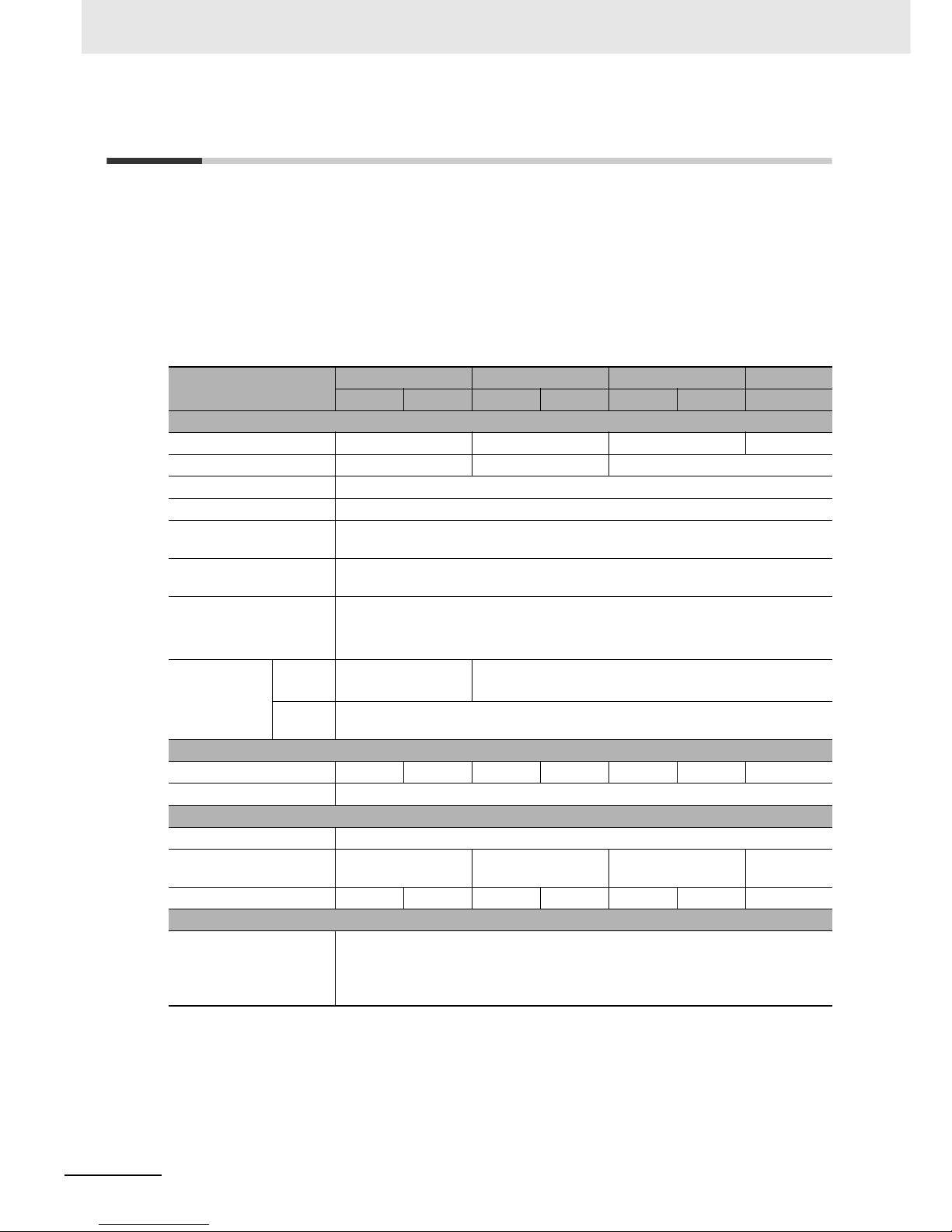
z Major Parameters
Note NB7W is used as the abbreviated name of NB7W-TWB hereinafter.
Models
NB3Q NB5Q NB7W NB10W
TW00B TW01B TW00B TW01B TW00B TW01B TW01B
Performance Specifications
Display Size 3.5”TFT LCD 5.6”TFT LCD 7”TFT LCD 10”TFT LCD
Resolution QVGA 320×240 QVGA 320×234 WVGA 800×480
Display Color 65536 colors
Backlight LED
Memory 128M FLASH + 64M DDR2 RAM
(NB-TW01B supports the USB storage)
Downloading Programs USB / Serial Port / Network Interface
(Only NB-TW01B supports the network interface downloading)
USB Port Equivalent of USB 2.0 Full speed
NB-TW00B: USB Slave ×1
NB-TW01B: USB Slave ×1, USB Host ×1
Communication
Por ts
Serial
Port
COM1: RS-232C/
422A/485
COM1: RS-232C
COM2: RS-232C/422A/485
Network
Interface
Only supported by the HMI of NB-TW01B
Electrical Specifications
Rated Power 5W 9W 6W 10W 7W 11W 14W
Rated Voltage DC24V
Structural Specifications
Case Color Black
Dimensions
W×H×D(mm)
129.8×103.8×52.8 184.0×142.0×46.0 202.0×148.0×46.0 268.8×210.8
×54.0
Weight 310g 315g 620g 625g 710g 715g 1545g
Software Tools
Version No. NB-Designer Ver1.2X
For download the application programs, please access your local Omron website. If
local site cannot be found, please access Omron IA global site
“http://www.ia.omron.com/” at first and select the area where you are.
Page 26
1-3
1 NB Overview
NB-series Programmable Terminals Startup Guide Manual(V109)
1-2 Part Names and Functions
1
1-2 Part Names and Functions
This section describes the names and functions of each part of the NB Unit.
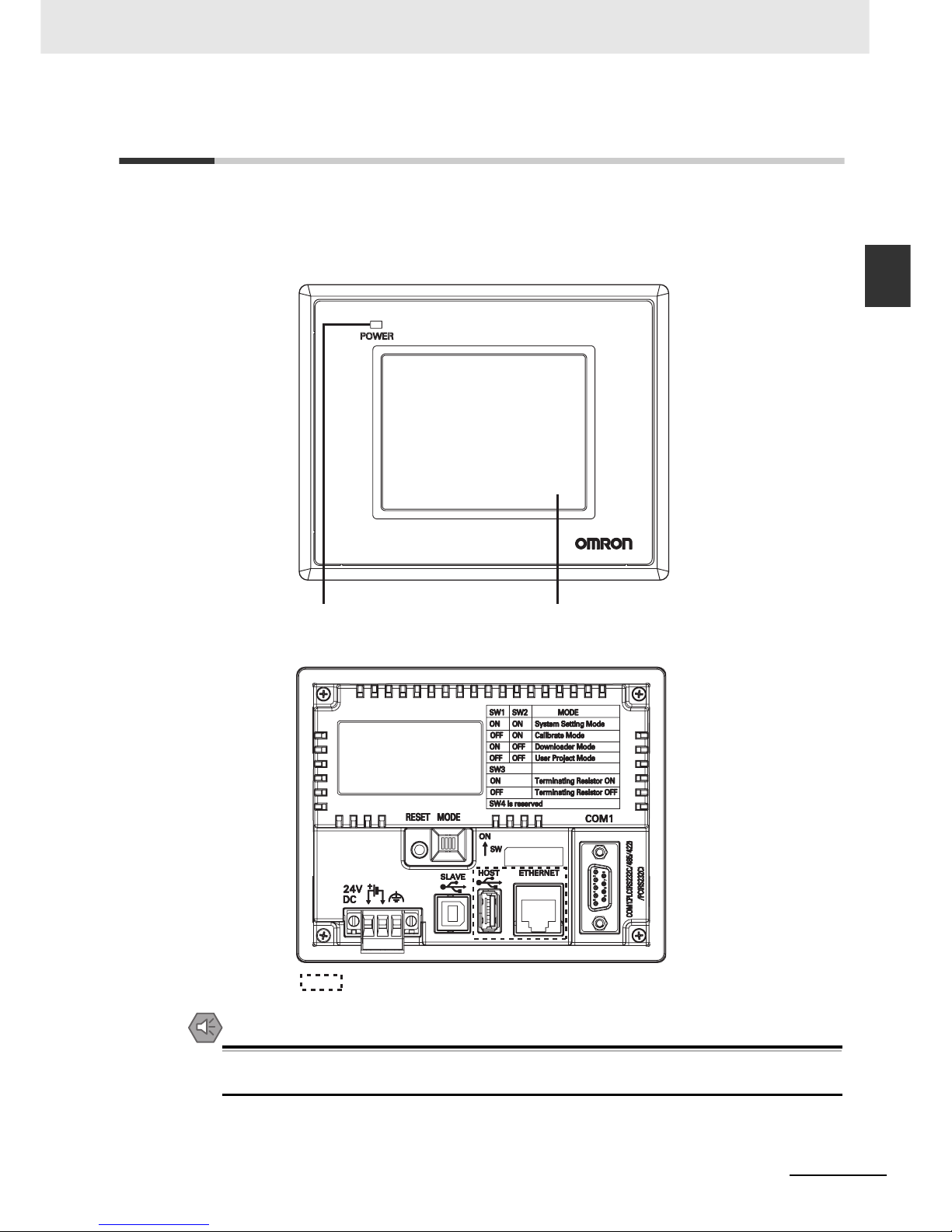
z NB3Q-TW00B/NB3Q-TW01B model
Front view
Back view
Precautions for Safe Use
Confirm the safety of the system before turning ON or OFF the power supply, or pressing the
reset button.
Power Indicator Displa
y
: NB-TW01B only
Page 27
1 NB Overview
1-4
NB-series Programmable Terminals Startup Guide Manual(V109)
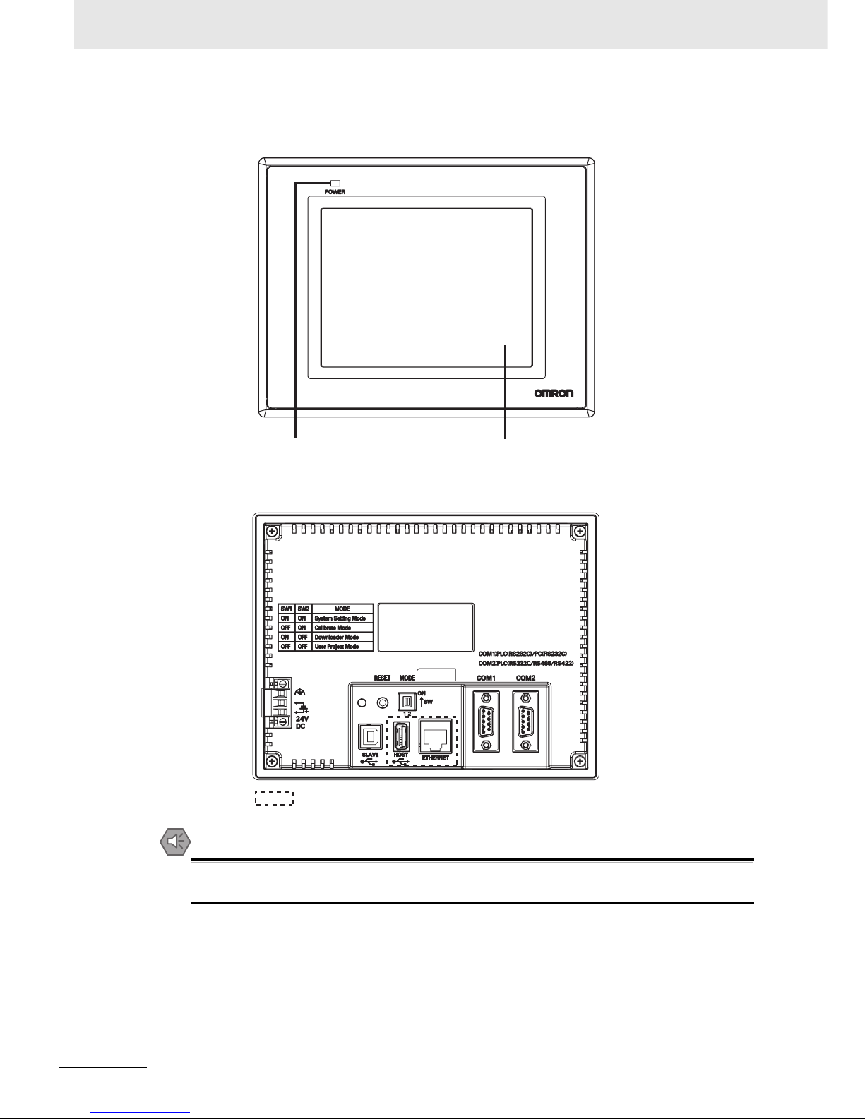
z NB5Q-TW00B/NB5Q-TW01B model
Front view
Back view
Precautions for Safe Use
Confirm the safety of the system before turning ON or OFF the power supply, or pressing the
reset button.
Power Indicator
Display
: NB-TW01B only
Page 28
1-5
1 NB Overview
NB-series Programmable Terminals Startup Guide Manual(V109)
1-2 Part Names and Functions
1
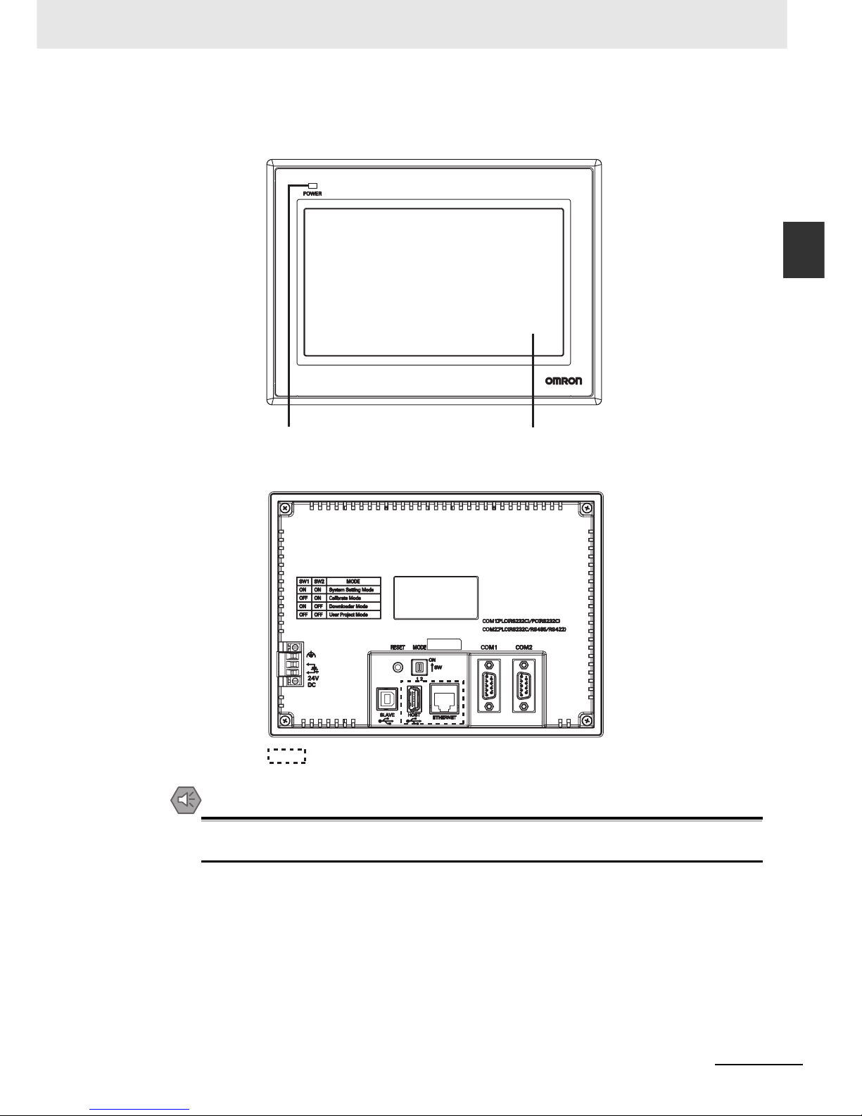
z NB7W-TW00B/NB7W-TW01B model
Front view
Back view
Precautions for Safe Use
Confirm the safety of the system before turning ON or OFF the power supply, or pressing the
reset button.
Power Indicator
Display
: NB-TW01B only
Page 29
1 NB Overview
1-6
NB-series Programmable Terminals Startup Guide Manual(V109)
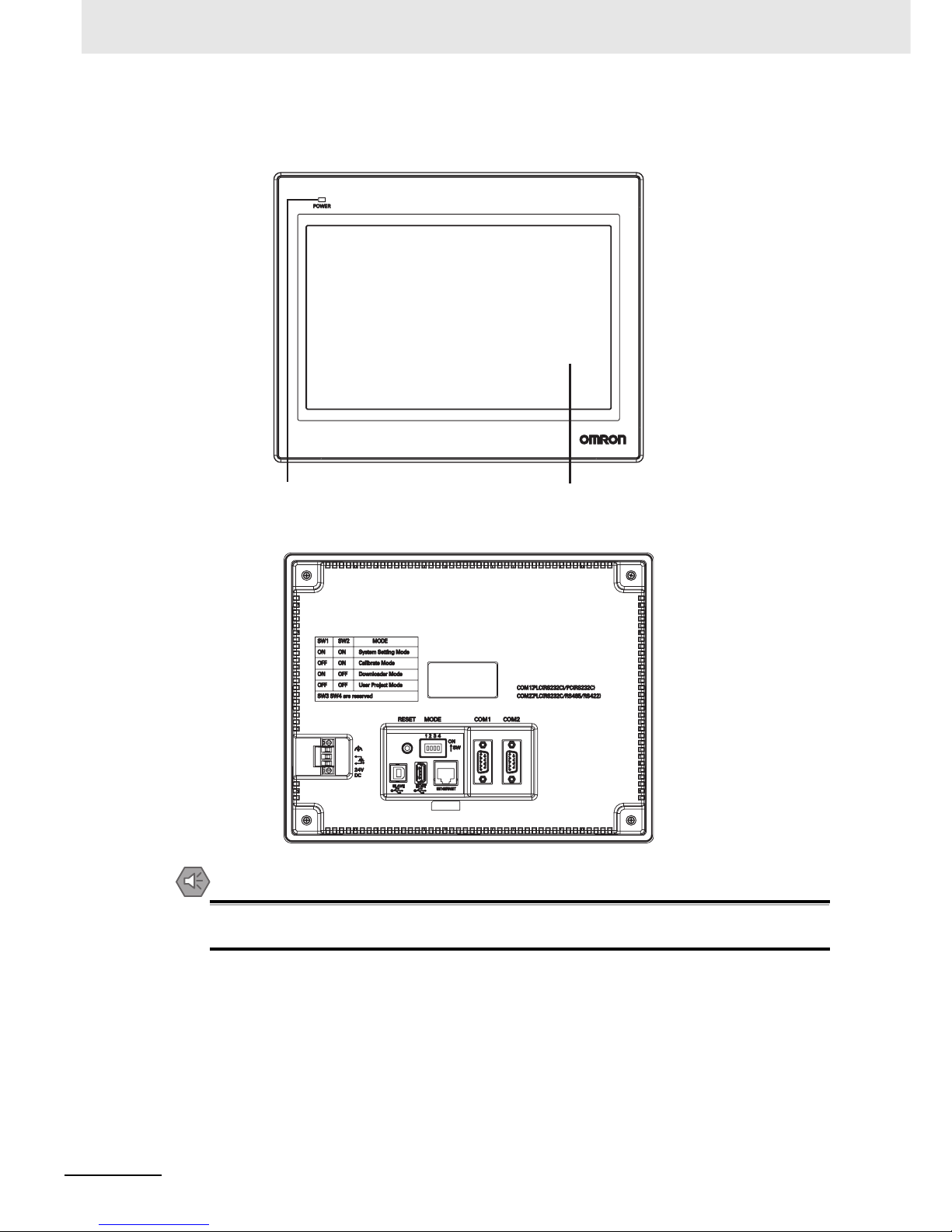
z NB10W-TW01B model
Front view
Back view
Precautions for Safe Use
Confirm the safety of the system before turning ON or OFF the power supply, or pressing the
reset button.
Power Indicator
Display
Page 30
1-7
1 NB Overview
NB-series Programmable Terminals Startup Guide Manual(V109)
1-2 Part Names and Functions
1
z Serial Port COM1
• NB5Q/NB7W/NB10W-TWB
Serial port COM1 is a 9-pin D-type socket port. This port supports RS-232C communication
function, making it connectable to a controller which features RS-232C function, and it can also be
used for downloading programs or debugging for the product.
The pins are defined as follows:
Precautions for Safe Use
When using the No. 6 pin of the serial communications port COM1 connector for a voltage of
DC+5V, make sure the supply equipment’s current capacity is below 250 mA before using it. The
DC+5V voltage output of the NB Unit is +5V±5%, and the maximum current is 250 mA.
• NB3Q-TWB
NB3Q-TWB has only 1 serial port COM1, and this port supports communication based on
RS-232C, RS-422 and RS-485, of which only 1 connection mode can be applied at one time. By
means of the RS-232C mode (PIN 2~5), it can be connected to a controller based on RS-232C,
and can also be used for downloading programs, as well as debugging for the product (connected
to a PC). While with the RS-422 or the RS-485 mode (PIN 1, PIN 6~8), only a PLC can be
connected.
The pins are defined as follows:
* Pins 4 and 5 are not used, thus not compliant with RS or CS functions.
Pins Signals I/O Functions
1NC - 2 SD O Sending data
3 RD I Receiving data
4 RS(RTS) O Request to send*
5 CS(CTS) I Clear to send*
6 DC+5V - DC+5V output (Max. current: 250mA)
7NC - 8NC - 9 SG - Signal ground
* Pins 4 and 5 are not used, thus not compliant with RS or CS functions.
Pins Signals I/O
Functions
RS-232C RS-485 RS-422A
1 SDB+ I/O - - Sending data(+)
2SD O
PLC Sending data
--
3RD I
PLC Receiving data
--
4 RS(RTS) O
Request to send*
-5 CS(CTS) I Clear to send* - 6 RDB+ I/O - RS485B
Send/Receive
data(+)
Receiving
data(+)
7 SDA- I/O - - Sending data(-)
8 RDA- I/O - RS485A
Send/Receive
data(-)
Receiving
data(-)
9 SG - Signal ground
Page 31

1 NB Overview
1-8
NB-series Programmable Terminals Startup Guide Manual(V109)
z Serial Port COM2
• NB5Q/NB7W/NB10W-TWB
Serial port COM2 is a 9-pin D-type socket port. This port supports RS-232C/RS-485/RS-422A
communication function.
The pins are defined as follows:
z USB HOST
NB-TW01B is equipped with USB HOST port, which is USB A-type port. Through this port, USB
memory can be connected to perform uploading, downloading, project operation and storage of related
data. And its pins are defined as follows:
Precautions for Safe Use
When connecting the equipment with the USB HOST connector, make sure the supply
equipment's current capacity is below 150mA before using it. The DC+5V voltage output of the
NB Unit is +5V±5%, and the maximum current is 150mA.
z USB SLAVE
USB SLAVE port is USB B-type port, which can connect the USB port on PC side to perform the
uploading, downloading and debugging of the programs for the product. And its pins are defined as
follows:
Pins Signals I/O
Functions
RS-232C RS-485 RS-422A
1 SDB+ I/O - - Sending data(+)
2 SD O Sending data - 3 RD I Receiving data - 4 Terminal R1 - - Terminal resistor 1
5 Terminal R2 - - Terminal resistor 2
6 RDB+ I/O - Send/Receive
data(+)
Receiving
data(+)
7 SDA- I/O - - Sending data(-)
8 RDA- I/O - Send/Receive
data(-)
Receiving
data(-)
9 SG - Signal ground
1 2 3 4
Pins Signals Functions
1 Vbus USB +5V power supply output
(Max. current: 150mA)
2 D- Data 3 D+ Data +
4 GND USB power supply ground
3
41
2
Pins Signals Functions
1 Vbus USB +5V power supply output
2 D- Data 3 D+ Data +
4 GND USB power supply ground
Page 32

1-9
1 NB Overview
NB-series Programmable Terminals Startup Guide Manual(V109)
1-2 Part Names and Functions
1
z Ethernet Interface
NB-TW01B is equipped with Ethernet Interface, which is adaptive RJ-45 type interface with the
transmission rate of 10M / 100M. It can be connected with PC to perform the uploading and
downloading of the programs and the system refreshing, and can also be used to realize the
communication with the controller supporting the Ethernet communication. And its pins are defined as
follows:
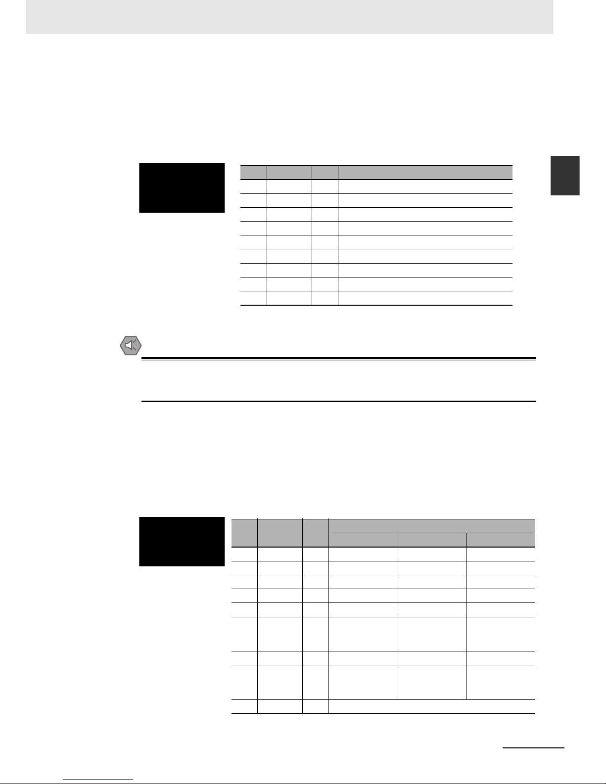
z DIP Switch
NB5Q/NB7W only has 2 switches SW1 and SW2, while for the NB3Q and NB10W, there are totally 4
DIP switches, and for all models, SW1 and SW2 feature the same functions. The settings and
corresponding operating modes are as follows:
• System Setting Mode: The PT will be launched into a built-in system setup screen, and is subject to
the user for brightness, system time and buzzer settings.
• Calibrate Mode: When the user touches the panel, a symbol “+” will pop up on the screen, with which
the touch control precision level can be calibrated.
• Downloader Mode: This is used for basic operations such as updating the firmware, downloading and
uploading the user’s engineering documents, etc. and this mode is not intended for general users.
• User Project Mode: This is the User Project Mode of NB-Series PTs. The PT will display the startup
screen of the project already downloaded.
As mentioned above, the settings and corresponding operating modes of the switches SW1 and SW2
of NB3Q and NB10W are the same as those of NB5Q/NB7W (see the table above), and the functions of
SW3 and SW4 of NB3Q and NB10W are stated as below:
z Reset Switch
When pressing the reset switch located on the back side of the PT, the system will be rebooted.
1
1
8
8
Pins Signals Functions
1 TD+ Sending data +
2 TD- Sending data 3 RD+ Receiving data +
4---Not used
5---Not used
6 RD- Receiving data 7---Not used
8---Not used
TOP Bottom
ON
ON
12
SW1 SW2 Operating modes
ON ON System Setting Mode
OFF ON Calibrate Mode
ON OFF Downloader Mode
OFF OFF User Project Mode
Switch No.
(corresponding model(s))
Status Descriptions of Function
SW3 (NB3Q)
ON Terminal resistance ON
OFF Terminal resistance OFF
SW3 (NB10W) Reserved
SW4 (NB3Q/NB10W) Reserved
ON
1
2
3
4
Page 33

1 NB Overview
1-10
NB-series Programmable Terminals Startup Guide Manual(V109)
Page 34

2-1
NB-series Programmable Terminals Startup Guide Manual(V109)
2
Ü
This section describes the manual structure, takes NB7W as an example to introduce
the operation procedures of the NB system.
2-1 About this Manual . . . . . . . . . . . . . . . . . . . . . . . . . . . . . . . . . . . . . . . . . . . . . 2-2
2-2 Demonstration System . . . . . . . . . . . . . . . . . . . . . . . . . . . . . . . . . . . . . . . . . 2-3
System Design
Page 35

2 System Design
2-2
NB-series Programmable Terminals Startup Guide Manual(V109)
2-1 About this Manual
This section describes the manual structure and operation procedures of the NB7W system.
z Manual Structure
The structure of the NB system (Take NB7W as an example) is described in the following sequence
in this manual:
The examples of circuit configuration, wiring and applications are used for reference only. Be sure to
refer to the relevant manuals for the specifications, performance and safety of each component
when configuring practical systems.
Chapter 1. NB overview, NB model and components names description
Chapter 2. Introduce example, components and program applications
Chapter 3. Installation and wiring
Chapter 4. Screen Creation
Chapter 5. Start running
Chapter 6. Maintenance and troubleshooting
Page 36

2-3
2 System Design
NB-series Programmable Terminals Startup Guide Manual(V109)
2-2 Demonstration System
2
2-2 Demonstration System
This section takes garage door control as a demonstration system. After NB-Designer is installed, the
project file of this demonstration system will be shown in the Start Menu. Click [Sample Screen(NB7)] in
the [Start]-[All Programs]-[OMRON]-[NB-Designer]-[Screen Data] to open the demonstration project.
Please note that the demonstration project includes macro files, so it can only be edited by running as
an administrator in Vista or Win7 systems. Run the NB-Designer as the administrator, and then open the
demonstration project in the [project]-[DemoProject_NB7W] file of NB-Designer’s installation directory.
z Operation
The demonstration system opens/closes the garage door according to inputs from NB7W and the sensors.
•
The garage door opens when the sensors detect three times of flash of headlights within 10 seconds.
• The state of garage door is displayed on NB7W. The open, close or stop operations of garage
door can also be controlled by related switches on display device.
a Light sensor b OPEN switch
c STOP switch d CLOSE switch
a
b
c
d
a
a Vehicle sensor
Page 37

2 System Design
2-4
NB-series Programmable Terminals Startup Guide Manual(V109)
• The garage door will not be closed before the CLOSE switch is pressed or the vehicle sensor is
ON after being fully opened.
a [Deactivate Auto-close] button
• The garage door will be closed when the sensors detect that the entire vehicle is in the garage.
• If [Deactivate Auto-close] button is pressed, the garage door will not be closed even if the vehicle
sensor is ON.
• Please control the garage door using related switches on the display device when the vehicle is
being driven out of the garage.
a Maintenance button
• NB7W will display maintenance screen for checking input devices when the maintenance button is
pressed.
z System Components
The following components are used in the garage door control system:
Display device
• NB7W-TWB
• XW2Z-200T(PT-PLC connecting cable: 2m)
• XW2Z-500T(PT-PLC connecting cable: 5m)
PLC
• CP1E-N20D- (20-dot I/O type)
Programming device and software
• Personal computer
• USB cable (A-type connector(male) - B-type connector(female))
• NB-Designer Ver1.1X (screen programming tool for NB series)
• CX-Programmer (PLC programming tool)
a
a
Page 38

2-5
2 System Design
NB-series Programmable Terminals Startup Guide Manual(V109)
2-2 Demonstration System
2
Input
• OPEN / STOP / CLOSE switches;
SW1 / SW2 / SW3 (Function Keys on the NB7W screen)
• Vehicle sensor: SEN1
• Light sensor: SEN2
• Limit switch, being ON when the garage door is fully opened: LS1
• Limit switch, being ON when the garage door is fully closed: LS2
Output
• The contact for activating the motor controlling the door opening: M01
• The contact for activating the motor controlling the door closing: M02
z CP1E
The CP1E is an economical PLC with high performance, which can be ideally used for small-scale
manufacturing machines and control systems.
The CP1E-N20D- is shown below:
Please refer to the SYSMAC CP series CP1E CPU Unit User Manual for details on CP1E.
LS1
MO1
MO2
LS2
SEN2
SW1
SW2
SW3
SEN1
Page 39

2 System Design
2-6
NB-series Programmable Terminals Startup Guide Manual(V109)
z System addresses allocation table
Memory allocation table
The I/O relays of the PLC are allocated as follows.
Addresses Function Component Name Corresponding Screen
W_bit 0.01 Automatically close
(disabled)
Bit State Setting Fully Open
W_bit 0.02 Start the maintenance
screen
Bit State Setting Wait
W_bit 1.00 Open Bit State Setting/
Bit State Lamp
All Screens/Check 2
W_bit 1.01 Stop Bit State Setting/
Bit State Lamp
All Screens/Check 2
W_bit 1.02 Close Bit State Setting/
Bit State Lamp
All Screens/Check 2
LW.B 10.0 Texts on screen flash Bit State Lamp Stop
C_word 0 Counter address Bar Picture,
Number Display
Wait, Check 3
T_word 0 Timer address Number Display Check 3
D_word 0 Switch window PLC Control D_word 11 Output window No. PLC Control CIO_bit 0.03~0.06 (See the following table) Bit State Lamp Check 1
Equipments Contactors Addresses
Vehicle sensor SEN1 0.03
Light sensor SEN2 0.04
Upper limit LS LS1 0.05
Lower limit LS LS2 0.06
Motor for opening control (Rise motor) MO1 100.00
Motor for closing control (Down motor) MO2 100.01
LS1(0.05)
MO1(100.00)
MO2(100.01)
LS2(0.06)
SEN2(0.04)
SEN1(0.03)
Page 40

2-7
2 System Design
NB-series Programmable Terminals Startup Guide Manual(V109)
2-2 Demonstration System
2
z NB7W Screen
The screens below will be displayed on NB7W.
(1) WAIT
The screen will be displayed when the garage door is fully closed. The number of flash of
headlights is indicated in the form of Bar Picture. The transparent button on the upper left
corner is used for switching to the maintenance screen.
(2) OPEN
The screen will be displayed when the motor for opening control is activated.
(3) CLOSE
The screen will be displayed when the motor for closing control is activated.
(4) STOP
The screen will be displayed when the STOP switch is pressed.
Page 41

2 System Design
2-8
NB-series Programmable Terminals Startup Guide Manual(V109)
(5) FULLY OPEN
The screen will be displayed when the garage door is fully opened. There is a button for
keeping the garage door open.
(6) CHECK 1
This screen is used for maintenance by displaying the input states of the sensors. The
screen will be displayed when the maintenance button on [1 WAIT] screen is pressed.
(7) CHECK 2
This maintenance screen can check the operation through displaying the input states of
Function Keys.
(8) CHECK 3
The current values of the timer and counter (used for counting flash times of headlights)are
displayed on this screen which is used for maintenance.
Page 42

2-9
2 System Design
NB-series Programmable Terminals Startup Guide Manual(V109)
2-2 Demonstration System
2
The screen switch flow chart is shown below.
1.Wait
2.Open
5.Full Open 4.Stop 8.Check 3
7.Check 2
6.Check 1
3.Close
Headlight
Status ON
Open
Button ON
Open
Button ON
Stop
Button ON
Maintenance
Button ON
Waiting Screen
Button ON
Next Screen
Button ON
Next Screen
Button ON
Last Screen
Button ON
Last Screen
Button ON
Stop
Button ON
Upper limit
LS ON
Car enter
Status ON
Close
Button ON
Close
Button ON
Lower limit
LS ON
Waiting Screen
Button ON
Page 43

2 System Design
2-10
NB-series Programmable Terminals Startup Guide Manual(V109)
z Ladder programs
The ladder program examples are shown below.
Refer to the SYSMAC CP series CP1E Software Manual and SYSMAC CX-Programmer Operation
Manual for details on creating ladder programs.
Page 44

2-11
2 System Design
NB-series Programmable Terminals Startup Guide Manual(V109)
2-2 Demonstration System
2
Page 45

2 System Design
2-12
NB-series Programmable Terminals Startup Guide Manual(V109)
Page 46

3-1
NB-series Programmable Terminals Startup Guide Manual(V109)
3
This section describes how to install and wire the NB Unit.
3-1 Installation . . . . . . . . . . . . . . . . . . . . . . . . . . . . . . . . . . . . . . . . . . . . . . . . . . . 3-2
3-2 Equipment Wiring . . . . . . . . . . . . . . . . . . . . . . . . . . . . . . . . . . . . . . . . . . . . . 3-5
Installation and Wiring
Page 47

3 Installation and Wiring
3-2
NB-series Programmable Terminals Startup Guide Manual(V109)
3-1 Installation
This section describes the installation environment of the NB Unit and how to mount the NB Unit to the
control panel.
When mounting the NB unit onto the operation panel, pay attention to the following precautions.
Precautions for Correct UsePrecautions for Correct Use
• Do not install the Unit in any of the following locations:
Locations subject to rapid changes in temperature
Locations subject to temperatures or humidity outside the range specified in the specifications
Locations subject to condensation as the result of high humidity
Locations subject to corrosive or flammable gases
Locations subject to strong shock or vibration
Locations outdoors subject to direct wind and rain
Locations subject to strong ultraviolet light
Locations subject to dust
Locations subject to direct sunlight
Locations subject to splashing oil or chemicals
• Take appropriate and sufficient countermeasures when the product is used in the following
locations:
Locations subject to static electricity or other forms of noise
Locations subject to strong electric field or magnetic field
Locations close to power supply lines
Locations subject to possible exposure to radioactivity
Precautions for Safe Use
When unpacking the NB Units and the peripheral devices, check carefully for any external
scratches or other damages. Also, shake the Unit gently and check for any abnormal sound.
Always ensure that the personnel in charge confirm that installation, inspection, and
maintenance were properly performed for the NB Unit.
“Personnel In charge” refers to individuals qualified and responsible for ensuring
safety during machine design, installation, operation, maintenance, and disposal.
Ensure that installation and post-installation checks are performed by personnel in
charge who possess a thorough understanding of the machinery to be installed.
WARNING
Page 48

3-3
3 Installation and Wiring
NB-series Programmable Terminals Startup Guide Manual(V109)
3-1 Installation
3
z Mounting NB Unit to Control Panel
Install the NB Unit by embedding it into the operation panel.
Use the panel mounting brackets and Phillips screwdriver installation.
Proceed the installation following the procedures below.
1
Panel cutout with dimensions is shown below. Fit the NB Unit into the panel from the front side.
2
As follows, insert the panel mounting brackets at the locations indicated by red box around the
back of the NB Unit. Insert the hooks of positioners into the square holes on the Unit to hold the
fixators properly, and tighten the screws firmly with the screwdriver.
z NB5Q/NB7W-TWB
Models Opening Dimension (W¯H mm)
NB3Q-TW00B/TW01B 119.0(+0.5/-0)¯93.0(+0.5/-0)
NB5Q-TW00B/TW01B 172.4(+0.5/-0)¯131.0(+0.5/-0)
NB7W-TW00B/TW01B 191.0(+0.5/-0)¯137.0(+0.5/-0)
NB10W-TW01B 258.0(+0.5/-0)¯200.0(+0.5/-0)
Width
Opening dimensions
Height
Page 49

3 Installation and Wiring
3-4
NB-series Programmable Terminals Startup Guide Manual(V109)
z The insert positions on the body of NB3Q-TWB/NB10W-TW01B (same
fixing method as above)
Precautions for Safe Use
• Do not let metal particles enter the Units when preparing the panel.
• The mounting panel must be between 1.6 and 4.8 mm thick. Tighten the Mounting Brackets
evenly to a torque of between 0.5 and 0.6 N·m to maintain water and dust resistance. If the
tightening torque exceeds the specified value, or the tightening is not even, deformation of
the front panel may occur. What is more, make sure the panel is not dirty or warped and that
it is strong enough to hold the Units.
z Display Mode of NB Series touch panel
NB Series touch panel has 2 display modes: horizontal and vertical.
The display mode can be selected when dragging a HMI from the Graph element window into the
Construct Window.
NB3Q -TWB
NB10W -TWB
Horizontal displa
y
Vertical displa
y
Menu Task Bar
Menu Task Bar
Page 50

3-5
3 Installation and Wiring
NB-series Programmable Terminals Startup Guide Manual(V109)
3-2 Equipment Wiring
3
3-2 Equipment Wiring
This section describes the wiring of the NB Unit and CP1E.
Precautions for Safe Use
• Do not connect an AC power supply to the DC power terminals.
• Use a DC power with a slight voltage fluctuation and that will provide a stable output even if the
input is momentarily interrupted for 10 ms.
Rated Power Supply Voltage: DC 24 V (Allowable range DC 20.4 ~ 27.6 V)
The connectable power supply specifications are as follows: figure out a suitable power supply
specification so as to satisfy the requirement for power supply capacity.
z NB5Q/NB7W/NB10W-TWB
z NB3Q -TWB
Power Supply
Models Rated Voltage Allowable Voltage Range Power
NB3Q-TW00B DC24V DC20.4V to 27.6V 5W
NB3Q-TW01B 9W
NB5Q-TW00B 6W
NB5Q-TW01B 10W
NB7W-TW00B 7W
NB7W-TW01B 11W
NB10W-TW01B 14W
0V
The reverse side of NB
MCCB
DC24V
24V
0V
The reverse side of NB
MCCB
DC24V
24V
Page 51

3 Installation and Wiring
3-6
NB-series Programmable Terminals Startup Guide Manual(V109)
Precautions for Safe Use
• Making the connection by using terminal screws crimping on a twisted-pair cable with a
crimping range of 12~26 AWG, and only 6.5 mm of insulation peel of the cable needs to be
peeled off. Tighten the terminal screws at a torque of between 0.3 and 0.5 N·m. Make sure
the screws are properly tightened.
The NB unit has a functional earthing terminal ( ).
Arrange the wiring according to the following conditions.
1
When a potential difference occurs between the NB Unit and the host, arrange the earthing as
illustrated. If the distance is too long to realize a single-point earthing, do not ground the
earthing terminal of the NB Unit.
2
When the NB Unit, and noise source equipments such as motors and inverters, etc. are
installed on the same panel, do not ground the earthing terminal of the NB unit.
Precautions for Safe Use
To prevent malfunctions caused by noise, ground the Unit correctly.
This section provides a CP1E grounding example.
Please refer to the SYSMAC CP series CP1E CPU Unit User Manual for details on CP1E.
z Power Connection and Grounding
Connect power and ground wires to terminal blocks.
Note Tighten the AC power cable to the terminal block at a torque of between 0.3 and 0.5 N·m. Loose screws may
occasionally result in fire or failure.
Grounding
CP1E Wiring
NB7W
CP1E
RS
MCCB
L1 COM 01
00 02 04 06 08 10
03 05 07 09 11
L2/N
Page 52

3-7
3 Installation and Wiring
NB-series Programmable Terminals Startup Guide Manual(V109)
3-2 Equipment Wiring
3
z Connecting I/O Devices
Connect I/O devices to the terminal block.
Execute One-to-one connection between the Host (PLC) and the NB Unit.
Connect CP1E and NB7W with a PT-PLC connecting cable (XW2Z-200T).
Note Please use OMRON PT-PLC connecting cable. Using other cables may result in failure.
Precautions for Safe Use
• Always keep the connector screws firmly tightened after the communication cable is
connected.
• The maximum tensile load for cables is 30 N. Do not apply loads greater than this.
• Turn OFF the power supply before connecting or disconnecting cables.
Connecting NB Unit and CP1E
SEN1 LS1
(0.03) (0.05)
L1 L2/N COM 01 03 05 07 09 11
00 02 04 06 08 10
SEN2 LS2
(0.04) (0.06)
Input
MO1
(100.00)
MO2
(100.01)
LL
00 01 02 03 04 050607
COM COM COM COMNC NC
Output
NB
RS-232C(15m max)
CP1E
Page 53

3 Installation and Wiring
3-8
NB-series Programmable Terminals Startup Guide Manual(V109)
Page 54

4-1
NB-series Programmable Terminals Startup Guide Manual(V109)
4
This section describes how to create a demonstration project through NB-Designer.
4-1 Starting NB-Designer . . . . . . . . . . . . . . . . . . . . . . . . . . . . . . . . . . . . . . . . . . . 4-2
4-2 Main Window of NB-Designer . . . . . . . . . . . . . . . . . . . . . . . . . . . . . . . . . . . . 4-3
4-3 Creating Project . . . . . . . . . . . . . . . . . . . . . . . . . . . . . . . . . . . . . . . . . . . . . . . 4-5
4-4 Screen Creation . . . . . . . . . . . . . . . . . . . . . . . . . . . . . . . . . . . . . . . . . . . . . . 4-13
4-5 HMI Attribute . . . . . . . . . . . . . . . . . . . . . . . . . . . . . . . . . . . . . . . . . . . . . . . . . 4-27
4-6 Save and Load Project . . . . . . . . . . . . . . . . . . . . . . . . . . . . . . . . . . . . . . . . . 4-28
Screen Creation
Page 55

4 Screen Creation
4-2
NB-series Programmable Terminals Startup Guide Manual(V109)
4-1 Starting NB-Designer
This section describes how to start NB-Designer.
NB-Designer is a programming tool (software) for creating screens displayed on NB7W.
Select [Start]-[All Programs]-[OMRON]-[NB-Designer_enu]-[NB-Designer_enu].
Starting NB-Designer.
The startup can also be realized by clicking the shortcut icon on the desktop.
(Note: When using Vista/Win7 systems, run the NB-Designer as an administrator.)
The main window will be displayed after starting NB-Designer completely.
Note Please refer to the NB-Designer Operation Manual for details of NB-Designer, such as the operating
environment, installation and operation.
Page 56

4-3
4 Screen Creation
NB-series Programmable Terminals Startup Guide Manual(V109)
4-2 Main Window of NB-Designer
4
4-2 Main Window of NB-Designer
This section describes the functions of each part of the main window of NB-Designer.
(a) Title Bar
Indicating the names of applications.
(b) Menu Bar
Classifying the functions of NB-Designer in groups. Grouping functions are indicated in the form of
pull-down menu.
(c) Toolbar
Displaying icons for common functions. The function names will be indicated when the cursor is put
on related icons. The toolbar contains sub-toolbars for basic functions, such as drawing, position,
system, page up/down, database, compilation and debugging, etc.
(d) Graph Element Window
The Graph Element Window contains: Communication Connection, HMI, PLC, PLC Parts,
Function Parts and Project Database.
(e) Message Window
Displaying the compilation process of a project and providing compilation error information.
(f) State Bar
Displaying information such as the current cursor position, the width/height of the target object and
the editing state, etc.
(g) Design Window
The window is used for designing images and setting the communication method between the HMI
and PLC.
g
h
i
f
e
d
c
b
a
Page 57

4 Screen Creation
4-4
NB-series Programmable Terminals Startup Guide Manual(V109)
(h) Project Files Window
The Window adopts a tree structure to show the correlations between the project-related touch
panel and macro files & BMP files.
(i) Project Structure Window
The Window adopts a tree structure chart to show the relations of the PLC, HMI, internal windows
and components of the HMI in the whole project.
Page 58

4-5
4 Screen Creation
NB-series Programmable Terminals Startup Guide Manual(V109)
4-3 Creating Project
4
4-3 Creating Project
This section describes how to configure settings of NB7W operations and create targets effectively. The
date created through NB-Designer are regarded as “Project”.
Project creation should be started with setting the configuration plan when using NB-Designer the first
time.
1
Select [File]-[New] from the main menu. The [New Project] dialogue border will pop up.
2
Select [NB7W-TW00B] from [HMI] Element Library, drag HMI to the design window after
selecting it with a single-click.
Select “horizontal” for HMI display Mode.
Note
This project can also be made by using HMI of NB7W-TW01B with the same method used for NB7W-TW00B.
Creating New Project
Drag it to the design
window after selecting
it with a single-click.
Page 59

4 Screen Creation
4-6
NB-series Programmable Terminals Startup Guide Manual(V109)
3
Select [Omron CP1H/L/E] from [PLC] Element Library, drag PLC to the design window after
selecting it with a single-click.
4
Select [Serial Port] from [Connector], drag it to the design window after selecting it with a singleclick.
Page 60

4-7
4 Screen Creation
NB-series Programmable Terminals Startup Guide Manual(V109)
4-3 Creating Project
4
5
Adjust the positions of HMI and PLC on the design window to connect serial communication
cables to COM1 of HMI and COM0 of PLC.
1
Click the project name on the project structure window and the connecting diagram of HMI and
PLC appears. Then double-click the HMI and “HMI Attribute” window pops up, select “COM1
Setting” page and set the communication mode to “RS232, 115200, 7, Even Parity Check, 2”.
Click OK button and the settings of the communication mode of HMI COM1 are completed.
Communication Setting
Page 61

4 Screen Creation
4-8
NB-series Programmable Terminals Startup Guide Manual(V109)
2
To setting the PLC: In “CX-Programmer” open the project, in project workspace select [PLC
Settings]. Be sure to set the communication mode of PLC [Built-in RS232C Port] to “RS232C,
115200, 7, Even Parity Check, 2”.
This project uses Macro files to initialize the addresses of LW.B 10.0 to 1, thus initializing the Bit State
Lamp on the [Stop] screen.
1
User could establish a macro file with the icon through the menus or toolbar.
Creating Macro
Page 62

4-9
4 Screen Creation
NB-series Programmable Terminals Startup Guide Manual(V109)
4-3 Creating Project
4
2
Then a macro code edit window will appear, use single right click in the “Parameters” window,
select “Add Variable”, a “Macro Code Variable” window will open, user can define variable
parameter with it.
3
After click “OK” there is a new parameter added in the “Parameters” window, it can be used in
macro program as a defined variable.
Please refer to 3-9 Macro Function in the NB-Designer Operation Manual for details.
With powerful vector graphics and bitmap libraries function in NB-Designer, users can create any
graphics such as switches, lights or tubes at will. Each vector graphic or bitmap contains 256 states.
Users can make the vector graphics in the system as templates, copy them into the new created vector
graphics, and then add lines, boxes, words etc. for them to generate the new vector graphics.
1
Select [Draw]-[New Graphics] from the main menu. The [New Graphics] window will appear.
Creating Vector Graphics
Page 63

4 Screen Creation
4-10
NB-series Programmable Terminals Startup Guide Manual(V109)
2
After create a new graphic, select “CTRL_BAR001.vg” in the project files window, select “state0”
and right single click graph below and select “Copy”.
3
Then select “Middle.vg” graphics, and copy the graphics to be copied into it. Copy the “state1”
into the graphics by the same method, and then select “Rectangle” in the toolbar to draw it into
the graphics.
Page 64

4-11
4 Screen Creation
NB-series Programmable Terminals Startup Guide Manual(V109)
4-3 Creating Project
4
4
Then make the settings in the “Graphics Attribute” dialog box to the geometric figures, as shown
below:
Note
Please save the project after the completing the creation of vector graphics.
5
Please create the vector graphics “Up.vg” (an upward hollow triangle) and “Down.vg”
(a downward hollow triangle) referring to the above-mentioned method.
Vector
graphics: Down.vg
Vector
graphics: Up.vg
Page 65

4 Screen Creation
4-12
NB-series Programmable Terminals Startup Guide Manual(V109)
6
Create a vector graphics “Dashed.vg”: first add a light cyan rectangle into the graphics, and then
make the related settings in the “Graphics Attribute” dialog box, as shown below:
7
Create a vector graphics “BlueFrame.vg”: first add a blue hollow rectangle into the graphics, and
then make the related settings in the “Graphics Attribute” dialog box, as shown below:
Page 66

4-13
4 Screen Creation
NB-series Programmable Terminals Startup Guide Manual(V109)
4-4 Screen Creation
4
4-4 Screen Creation
This part describes how to create screens displayed on NB7W.
[1 Wait] is the first display screen in the garage door control system. The screen will be displayed with
the lower limit LS ON.
Configure functions below:
• Bar Picture component, indicating numbers of flash of headlights detected in forms of graphics.
• Bit State Setting components, allocated to [Open], [Stop] and [Close] garage door operations
respectively.
• Bit State Setting component, for accessing the maintenance screen. The component turns ON when
the button is pressed for 3 seconds.
The whole screen is shown below. The following objects must be created and configured:
a Screen b Bit State Setting components c Texts d Bar Picture component
z Screen
Start the following procedures after the NB7W operation is set.
1
Select [Add Window] from the toolbar. Input “Wait” at the window name area.
[1 Wait]
a
c
d
b
Use the vector graphic: Up.vg
Address: W_bit 1.00
Use the vector graphic: Middle.vg
Address: W_bit 1.01
Use the vector graphic: Down.vg
Address: W_bit 1.02
[Open]
[Stop]
[Close]
The initial design frame ID is 0,
named “Frame0”, when user
added a new frame, the frame ID
start from 10 by default.
Frame 1 to 9 are default frames
for the system.
Page 67

4 Screen Creation
4-14
NB-series Programmable Terminals Startup Guide Manual(V109)
User should use this method to create totally 7 frames for this project, the frames ID and names
are listed as below:
2
Double-click “Wait” window to eject [Window Attribute], select “User Background Color” and set
“Fill Color” to “lightCyan”.
z Bit State Setting Component
1
Bit State Setting component for switching to the maintenance screen
The Bit State Setting component on the upper left corner is used for switching to the
maintenance screen ([6 Check 1] screen).
Function: The ladder programs of CP1E will switch the screen to [6 Check 1] after pressing it to
set W0.02 to be ON. The Function Key is set transparent and will not function until being
pressed for 3 seconds for the purpose of avoiding being pressed accidentally.
Select [Bit State Setting component] from [PLC Parts], drag it to the design window after
selecting it with a single-click.
The attribute settings are:
Frame ID Frame Name
10 Wait
11 Open
12 Close
13 Stop
14 Fully Open
15 Check1
16 Check2
17 Check3
Write Address W0.02
Bit State Setting Types On
Graphics Use the vector graphic:
Dashed.vg (A vector graphic created by user,
which is a light cyan rectangle)
Control Setting
(Security Setting)
Minimum press time 3s
Page 68

4-15
4 Screen Creation
NB-series Programmable Terminals Startup Guide Manual(V109)
4-4 Screen Creation
4
Page 69

4 Screen Creation
4-16
NB-series Programmable Terminals Startup Guide Manual(V109)
2
Bit State Setting component for Open/Stop/Close
Function: After the component is pressed, the bits for address switch (i.e. W_bit 1.00 (Open
switch) / W_bit 1.01 (Stop switch) / W_bit 1.02 (Close switch)) will be reset after being set to 1.
The attribute settings are:
z Fixed Text
Select the “Text” button on the drawing toolbar and set the attribute of fixed text.
z Bar Picture Component
The function of the Bar Picture Component is to indicate numbers of flash of headlights detected.
The times of flash are related to the current value of the ladder program counter. Up to 3 times of
flash can be counted when the maximum value of the Bar Picture is set to “3”.Put fixed texts [1], [2]
and [3] above the Bar Picture as the scale to indicate times of flash.
Select [Bar Picture] from [PLC Parts], drag it to the design window after selecting it with a singleclick.
Component Name Open Stop Close
Write Address W_bit 1.00 W_bit 1.01 W_bit 1.02
Bit State Setting Type Reset switch
Graphics Use the vector graphic:
Up.vg (A vector graphic
created by user, which
is an upward arrow)
Use the vector graphic:
Middle.vg (A vector
graphic created by user,
which is a square)
Use the vector graphic:
Down.vg (A vector
graphic created by user,
which is an downward
arrow)
Page 70

4-17
4 Screen Creation
NB-series Programmable Terminals Startup Guide Manual(V109)
4-4 Screen Creation
4
The attribute settings are:
The [2 Open] screen will be displayed when the motor for garage door opening control is activated.
Configure functions below:
• Fixed text indicating the garage door state.
• Bit State Setting components, allocated to [Open], [Stop] and [Close] garage door operations
respectively.
Read Address C_word 0
Bar Type Standard
Art Direction Left
Bar Shape Rectangle
Border Color Blue
Background Color Light grey
Normal Color Light cyan
Alarm Lower Color Light cyan
Min. / Max. Value 0/3
Alarm Lower Value 0
[2 Open]
Page 71

4 Screen Creation
4-18
NB-series Programmable Terminals Startup Guide Manual(V109)
The whole screen is shown below. The creating method is the same as that of [1 Wait].
a Screen b Fixed Text c Bit State Setting components
The [3 Close] screen will be displayed when the motor for garage door closing control is activated.
Configure functions below:
• Fixed text indicating the garage door state.
• Bit State Setting components, allocated to [Open], [Stop] and [Close] garage door operations
respectively.
The whole screen is shown below. The creating method is the same as that of [1 Wait].
a Screen b Fixed Text c Bit State Setting components
The [4 Stop] screen will be displayed when all the conditions below are satisfied.
• The opening and closing motors are not activated.
• The upper limit LS and lower limit LS are OFF.
• The Maintenance button is OFF.
Configure functions below:
• Bit State Lamp showing the garage door state. To make the whole screen flash to draw attention.
• Bit State Setting components, allocated to [Open], [Stop] and [Close] garage door operations
respectively.
[3 Close]
[4 Stop]
a
b
c
a
b
c
Page 72

4-19
4 Screen Creation
NB-series Programmable Terminals Startup Guide Manual(V109)
4-4 Screen Creation
4
The whole screen is shown below.
a Screen b Bit State Lamp c Bit State Setting components
The configuration of the Bit State Lamp is shown below. The creating method of the Bit State Setting
components is the same as that of [1 Wait].
z Bit State Lamp
The Bit State Lamp and macro file are used in this project to flash the prompt information.
1
Select [Bit State Lamp] from [PLC Parts], drag it to the design window after selecting it with a
single-click.
The attribute settings for the Bit State Lamp are:
Read Address LW.B 10.0
Function Value 1 Blinking state 1, value 0 Showing state 0
Rate 5∗100 ms
Ta g U se
0: blank
1: Shutter Stopped
a
b
c
Page 73

4 Screen Creation
4-20
NB-series Programmable Terminals Startup Guide Manual(V109)
2
To keep the Bit State Lamp in the Stop screen flashing together with the value of LW.B10.0 set to
1, we can initialize its values by creating the Macro file. The defining method for Macro has been
described in [Creating Project] part. After the project is downloaded into HMI, initialization by
using the Macro is required, i.e. selecting “macro_0.c” option after checking “Use INIT Macro” in
HMI Extended Attributes tab in HMI Attribute screen is required to perform the initialization (Refer
to 4-5 HMI Attribute for the setting method).
Page 74

4-21
4 Screen Creation
NB-series Programmable Terminals Startup Guide Manual(V109)
4-4 Screen Creation
4
The [5 Fully Open] screen will be displayed with the lower limit LS ON.
Configure functions below:
• Fixed text indicating the garage door state.
• Bit State Setting components for blocking inputs from vehicle sensors to prevent the garage door
from closing automatically.
• Bit State Setting components, allocated to [Open], [Stop] and [Close] garage door operations
respectively.
The whole screen is shown below. The creating methods for fixed text and Bit State Setting
components for [Open], [Stop] and [Close] garage door operations are the same as that of [1 Wait].
a Screen b Fixed Texts c Bit State Setting components
z Bit State Setting Components
Function: Block inputs from vehicle sensors. W0.01 turns ON and the input 0.03 from vehicle
sensors is blocked after the component is pressed. Herein, the garage door is to be closed through
manual operations on Function Keys. W0.01 will turn OFF when the garage door is closed and the
lower limit LS turns ON.
The attribute settings are:
The [6 Check 1] screen will be displayed when the maintenance button on [1 WAIT] screen is pressed.
Configure functions below:
• Fixed text indicating the garage door state.
• The Bit State Lamp components activating relevant lamp when the vehicle sensor, light sensor, upper
limit LS or lower limit LS turns ON.
• Function Key components, buttons for switching to [1 Wait] and [7 Check 2] screens.
• Bit State Setting components, allocated to [Open], [Stop] and [Close] garage door operations
respectively.
[5 Fully Open]
Write Address W0.01
Bit State Setting Type On
Ta g U s e
0: Deactivate Auto-close
1: Deactivate Auto-close
Graphics Use the vector graphic: CTRL_BAR001.vg
[6 Check 1]
a
b
c
Page 75

4 Screen Creation
4-22
NB-series Programmable Terminals Startup Guide Manual(V109)
The whole screen is shown below. The creating methods for fixed text and Bit State Setting
components for [Open], [Stop] and [Close] garage door operations are the same as that of [1 Wait].
a Screen b Fixed Texts c Bit State Lamp d Function Keys e Bit State Setting components
z Bit State Lamp
The states of the vehicle sensor, light sensor, upper LS and lower LS are shown by the lamp.
The attribute settings for the Bit State Lamp are:
z Function Key Components
These are used for switching to [1 Wait] and [7 Check 2] screens.
The attribute settings of the Function Key components are:
The [7 Check 2] screen will appear after the screen-switching button on [6 Check 1] or
[8 Check 3] screen is pressed.
Configure functions below:
• Fixed text indicating the garage door state.
• Bit State Lamp components activating relevant lamp to check operations when the [OPEN], [STOP]
or [CLOSE] Function Key turns ON.
• Function Key component, a button for switching to [6 Check 1] and [8 Check 3] screens.
• Bit State Setting components, allocated to [Open], [Stop] and [Close] garage door operations
respectively.
Corresponding
Name
Vehicle Sensor Light Sensor Upper LS Lower LS
Read Address CIO 0.03 CIO 0.04 CIO 0.05 CIO 0.06
Function Normal
Tag Do not use
Graphics Use the vector graphic: Lamp2State1-00.vg
Screen Name Wait Screen Next Screen
Function Key Switch to base window [1 Wait] Switch to base window [7 Check 2]
Tag Use tags:
0: Wait Screen
1: Wait Screen
Use tags:
0: Next Screen
1: Next Screen
Graphics Use the vector graphic: CTRL_BAR001.vg
[7 Check 2]
a
b
d
e
c
Page 76

4-23
4 Screen Creation
NB-series Programmable Terminals Startup Guide Manual(V109)
4-4 Screen Creation
4
The whole screen is shown below. The creating methods for fixed text and Bit State Setting
components for [Open], [Stop] and [Close] garage door operations are the same as that of [1 Wait].
a Screen b Fixed Texts c Bit State Lamp d Function Keys e Bit State Setting components
z Bit State Lamp
The states of the [OPEN], [STOP] and [CLOSE] switches are shown by the lamp.
The attribute settings for Bit State Lamp are:
z Function Key Components
These are used for switching to [6 Check 1] and [8 Check 3] screens.
The attribute settings for the Function Key components are:
The [8 Check 3] screen will be displayed when the screen-switching button on the
[7 Check 2] screen is pressed.
Configure functions below:
• Fixed text indicating the garage door state.
• Number Display components displaying the current values of TIM000 and CNT000 used in the ladder
program.
• Function Key components, buttons for switching to [7 Check 2] and [1 Wait] screens.
• Bit State Setting components, allocated to [Open], [Stop] and [Close] garage door operations
respectively.
Corresponding
Name
OPEN Switch STOP Switch CLOSE Switch
Read Address W_bit 1.00 W_bit 1.01 W_bit 1.02
Function Normal
Tag Use tags:
0: blank
1: OPEN
Use tags:
0: blank
1: STOP
Use tags:
0: blank
1: CLOSE
Graphics Use the vector graphic: Lamp2State1-00.vg
Screen Name Previous Screen Next Screen
Function Key Change window[6 Check 1] Change window[8 Check 3]
Tag Use tags:
0: Previous Screen
1: Previous Screen
Use tags:
0: Next Screen
1: Next Screen
Graphics Use the vector graphic: CTRL_BAR001.vg
[8 Check 3]
a
b
d
e
c
Page 77

4 Screen Creation
4-24
NB-series Programmable Terminals Startup Guide Manual(V109)
The whole screen is shown below. The creating methods for fixed text and Bit State Setting
components for [Open], [Stop] and [Close] garage door operations are the same as that of [1 Wait].
a Screen b Fixed Texts c Number Display components d Function Keys e Bit State Setting
components
z Number Display Components
The states of the [OPEN], [STOP] and [CLOSE] switches are shown by the lamp.
The attribute settings for the Bit State Lamp are:
z Function Key Components
These are used for switching to [1 Wait] and [7 Check 2] screens.
The attribute settings for the Function Key components are:
Corresponding Name TIM0 CNT0
Read Address T_word 0 C_word 0
Numeric Data Type Unsigned int
Graphics Use the vector graphic:
BlueFrame.vg (A vector graphic coming with user created, which consists of
a Number Display component plus a blue border)
Screen Name Previous Screen Wait Screen
Function Key Change window[7 Check 2] Change window[1 Wait]
Tag Use tags:
0: Previous Screen
1: Previous Screen
Use tags:
0: Wait Screen
1: Wait Screen
Graphics Use the vector graphic: CTRL_BAR001.vg
a
b
d
e
c
Page 78

4-25
4 Screen Creation
NB-series Programmable Terminals Startup Guide Manual(V109)
4-4 Screen Creation
4
In this project, the window is controlled by PLC, to realize this function, the PLC Control component
should be used.
Change Window and Write Data to PLC (Current Base Window) functions can be realized by using this
component. In this case, the default Word Length for the specified register is 2, and when this value is
changed to a value corresponding to a valid Window No., the system will automatically make the screen
switch to the screen corresponding to this valid Window No.. It can be known from the ladder program
that D_word 0 is used as the value of corresponding screen number and D_word 11 as the address of
output window number in this project.
z Change Window
Select [PLC Control] from [Project Database].
After clicking the Add button, make the settings in the PLC Control dialog box as shown below.
PLC Control Setting
Page 79

4 Screen Creation
4-26
NB-series Programmable Terminals Startup Guide Manual(V109)
After click [OK], there is a new event added in the control list.
z Write Data to PLC (Current Base Window)
Add another control event by the same method to make the current Window No. output from HMI to
PLC.
Then the PLC control setting has been done.
Refer to 3-8-5 PLC Control of NB-Designer Operation Manual for details on PLC control.
Page 80

4-27
4 Screen Creation
NB-series Programmable Terminals Startup Guide Manual(V109)
4-5 HMI Attribute
4
4-5 HMI Attribute
1
Select “Task Bar” page on “HMI Attribute” window and in this project example, the “Display Task
Bar” is not checked. Click OK button to save the settings.
2
Select “HMI Extended Attributes” page in “HMI Attribute” window and in this project example,
the “Use INIT Macro” item is selected and the “Initial Window” is set to “[10 Wait] screen”. Click
OK button to save the settings.
The default “Initial Window” is “0: Frame0” when HMI has not created a window screen. The serial
number and name of the window will appear in the pull-down menu of “Initial Window” after the user
establishes the window screen.
Page 81

4 Screen Creation
4-28
NB-series Programmable Terminals Startup Guide Manual(V109)
4-6 Save and Load Project
This part describes how to save and open data created. And it also introduces the plan testing function
and PLC programming console function.
z Save Project
1
Select [File]-[Save As] from the main menu. The [Project Save Path] dialogue border will pop up.
2
Designate [Save File] location and input the file name. Click OK. The NB-Designer project file is
saved.
Page 82

4-29
4 Screen Creation
NB-series Programmable Terminals Startup Guide Manual(V109)
4-6 Save and Load Project
4
z Open Projects
1
Select [File]-[Open] from the main menu. The [Open] dialogue border will pop up.
2
Designate the [Look in] location and select the file name. Single-click [Open]. Open the NBDesigner project file.
Page 83

4 Screen Creation
4-30
NB-series Programmable Terminals Startup Guide Manual(V109)
z Test function
The display effect of the created screen can be checked by the NB-Designer itself through the offline
simulation without need to connect it to the PLC. Select [Tools] - [Compile] from the main menu.
After the successful compilation, select [Tools] - [Offline Simulation] and then right-click the mouse
to select “close” to exit from the simulation. Please note that it needs to be recompiled and then
simulated each time when the setting or project is changed.
The offline simulation is convenient for users to preview the screen effect visually without need to
download programs to the HMI, thus enhancing the programming efficiency substantially, but the
offline simulation can only show the display effect of the project screen. Because this project
involves the data sampling and input/output control of PLC, the actual operating effect can be seen
only after the edited project being downloaded into HMI for operation and the communication with
PLC being established. If the user just wants to see the created screen effect, it needs to place one
Number Input component in the Common Window with the address of LW0 (for example), and then
add the same address into the PLC Control component with the Control Type of “Change Window”
in the PLC Control dialog box. In this case, each created window can be seen after the number of 10
to 17 input into the Number Input component during the offline simulation. Later, it just needs to
delete the Number Input component and the added control conditions after the correct confirmation.
Please refer to 3-14 Simulation in the NB-Designer Operation Manual for details on simulation.
Page 84

5-1
NB-series Programmable Terminals Startup Guide Manual(V109)
5
This section describes how to start running at the Host side and prepare to send
screen data to NB7W.
5-1 Preparations . . . . . . . . . . . . . . . . . . . . . . . . . . . . . . . . . . . . . . . . . . . . . . . . . . 5-2
5-2 Run NB7W . . . . . . . . . . . . . . . . . . . . . . . . . . . . . . . . . . . . . . . . . . . . . . . . . . . . 5-5
Run
Page 85

5 Run
5-2
NB-series Programmable Terminals Startup Guide Manual(V109)
5-1 Preparations
This part describes how to start running at the Host side (CP1E) and prepare to send screen data to
NB7W.
Use a USB cable to connect CP1E and a PC.
a. PC b. USB Cable c. CP1E
Note USB driver is needed to be installed when CP1E is connected to a PC the first time. Refer to the SYSMAC
CP series CP1E CPU Unit Operation Manual for details on installing USB driver.
CX-Programmer is a programming tool [software] for creating ladder programs executed by CP1E.
Aside from the programming function, it also provides functions for setting and operating CP1E, such as
debugging program addresses, indication of current values, monitoring function, PLC settings and
remote programming and monitoring through the internet, etc. Please refer to the SYSMAC CX-Programmer Operation Manual for details on CX-Programmer.
Run CP1E after sending programs to CP1E. Create CP1E programs using CX-Programmer.
1
Start CX-Programmer and open the created program.
2
Select [PLC]-[Work Online] from the main menu of CX-Programmer.
Connect CP1E and PC
Connect CP1E
a
b
c
Page 86

5-3
5 Run
NB-series Programmable Terminals Startup Guide Manual(V109)
5-1 Preparations
5
3
Select [PLC] - [Transfer] - [To PLC] from the main menu.
4
Send data according to the procedures described on the screen.
5
Select [PLC]-[Operating Mode]-[Run] from the main menu.
CP1E starts running.
z Using a USB cable to connect NB7W and a PC
The screen programs created by NB-Designer can be sent to NB7W.
Note • It is allowed to use USB cables of any standards.
• Use a USB cable with a maximum length of 5 m.
Connect NB7W and PC
Page 87

5 Run
5-4
NB-series Programmable Terminals Startup Guide Manual(V109)
Note USB driver for NB7W must be installed in the PC if USB is used to connect NB7W and the PC. The USB
driver should be installed automatically when NB-Designer is run on a PC the first time. Please refer to 2-4
Installation of USB Driver for NB in the NB-Designer Operation Manual for details on the USB driver.
z Using Ethernet to connect NB7W (NB-TW01B supporting Ethernet
connection) with PC
1
Make Network Setting in the [HMI] tab in [HMI Attribute] dialog box of NB-Designer. (e.g. IP is
192.168.250.1; Subnet Mask is 255.255.255.0 and Default Gateway is 0.0.0.0.)
2
Set the DIP Switch of this HMI to “1 ON” and “2 ON”, and then make the Network Setting: IP,
Port, Subnet Mask and Gateway (Network Setting also available for the HMI with Ethernet
interface).
3
Make the Network Setting in this mode same as that in the HMI tab of NB-Designer. (e.g. IP is
192.168.250.1 and Subnet Mask is 255.255.255.0.)
4
Restart the HMI, and then check if the IP and Subnet Mask are set successfully.
5
Set the IP address of PC and that of HMI locating in the same network segment with the first 3
parts being same and the last part being different (e.g. IP is 192.168.250.2 and Subnet Mask is
255.255.255.0.).
6
Use the network cable to connect HMI and PC, and then the project can be downloaded
immediately.
Note For the details of Ethernet connection, refer to NB-Designer Operation Manual.
Ethernet Cable
Page 88

5-5
5 Run
NB-series Programmable Terminals Startup Guide Manual(V109)
5-2 Run NB7W
5
5-2 Run NB7W
This part describes how to send screen programs of NB-Designer to NB7W .
1
Connect NB7W and a PC.
2
Start NB-Designer and open the screen program created.
3
Select [Tool]-[Compile] from the main menu. Select [Tool]-[Download] after compilation is
completed.
4
NB7W starts running after data sending is completed.
Page 89

5 Run
5-6
NB-series Programmable Terminals Startup Guide Manual(V109)
Note To download the project into USB for operation (NB-TW01B supporting this function), refer to 6-1-5
Download to USB1 in NB-Designer Operation Manual.
In this case, the exemplary project of garage door control system will work normally after the programs are
transferred to CP1E successfully by CX-Programmer and the project are downloaded into HMI successfully
by NB-Designer, as well as the NB Unit are connected with CP1E together with other devices according to
the requirements.
Page 90

6-1
NB-series Programmable Terminals Startup Guide Manual(V109)
6
This section describes the maintenance and inspection methods for preventing errors
occurring, and troubleshooting measures when errors occur.
6-1 Maintenance . . . . . . . . . . . . . . . . . . . . . . . . . . . . . . . . . . . . . . . . . . . . . . . . . . 6-2
6-2 Checking and Cleaning . . . . . . . . . . . . . . . . . . . . . . . . . . . . . . . . . . . . . . . . . 6-3
6-3 Troubleshooting . . . . . . . . . . . . . . . . . . . . . . . . . . . . . . . . . . . . . . . . . . . . . . . 6-5
6-3-1 Software Trouble . . . . . . . . . . . . . . . . . . . . . . . . . . . . . . . . . . . . . . . . . . . . . . . 6-5
6-3-2 Communication-related Troubles . . . . . . . . . . . . . . . . . . . . . . . . . . . . . . . . . . 6-26
6-3-3 Hardware Troubles . . . . . . . . . . . . . . . . . . . . . . . . . . . . . . . . . . . . . . . . . . . . . 6-30
6-3-4 Problems about FINS/UDP . . . . . . . . . . . . . . . . . . . . . . . . . . . . . . . . . . . . . . 6-32
6-3-5 Other Troubles . . . . . . . . . . . . . . . . . . . . . . . . . . . . . . . . . . . . . . . . . . . . . . . . 6-32
6-4 Unit Replacement Precautions . . . . . . . . . . . . . . . . . . . . . . . . . . . . . . . . . . 6-34
Maintenance and Troubleshooting
Page 91

6 Maintenance and Troubleshooting
6-2
NB-series Programmable Terminals Startup Guide Manual(V109)
6-1 Maintenance
This section describes the maintenance methods for preventing errors occurring.
Maintain the PT to keep it in its optimal condition.
z Backup of application
When the unit needs to be repaired due to the occurrence of some faults or to be replaced by the
substitute, be sure to make backup of the applications and keep it in a safe location.
z Spare part of Unit
It is recommended to prepare the spare part of NB Unit in advance in order to repair the system
when the faults occurred in NB Unit or the screen is not clear due to the backlight life expires.
z Replace of battery
The lithium battery is used for the backup of the non-screen data such as calendar data, clock data
etc.
The life of the battery is approximate 5 years at 25 °
C (1 year = 365 days ×12 hours /day). If the
battery is used at high temperature, its life will be reduced. Please replace the battery after the data
backup according to the operating environment.
Do not attempt to take the product apart and do not touch the product inside while the
power is being supplied. Otherwise it may result in electric shock.
Always ensure that the personnel in charge confirm that installation, inspection, and
maintenance were properly performed for the NB Unit.
“Personnel in charge” refers to individuals qualified and responsible for ensuring
safety during machine design, installation, operation, maintenance, and disposal.
Do not attempt to disassemble, repair, or modify the NB Unit. Otherwise it may impair
the safety functions.
WARNING
Page 92

6-3
6 Maintenance and Troubleshooting
NB-series Programmable Terminals Startup Guide Manual(V109)
6-2 Checking and Cleaning
6
6-2 Checking and Cleaning
This section describes the inspection and cleaning method for the NB Unit.
Please clean and check the NB Series periodically to ensure the NB Series always in the optimal
status.
z Cleaning method
If the display part is dirty, then the screen will hard to see. Please perform cleaning periodically
according to the following points:
• During the daily cleaning, please use the dry soft cloth. But if use the dry soft cloth to clean
forcefully when it is too dirty, the front panel may be damaged. In this case, use the wet cloth to
clean it in advance.
• When the dirt cannot be cleaned by dry cleaning, please dip the cloth into the diluted neutral
washing agents (concentration of 2%) completely first, and then perform cleaning after the wet
cloth is wringed out.
• Waste, ethylene products or tape sticking to the Unit for a long period will generate dirt. If there is
dirt sticking to the Unit, please remove it during the cleaning.
Precautions for Safe Use
Do not use benzene, paint thinner, or other volatile solvents, and do not use chemically treated
cloths.
z Checking method
Please perform checking once every 6 months to 1 year. But the frequent checking should be
necessary when the Unit is used in the extreme environments such as the environment with high
temperature, high humidity or more dust etc.
z Checking items
Please check the following items for the criterion. If the item does not conform to the criterion, please
improve the surrounding environment, retighten the screw etc. to make it conform to the criterion.
Checking Items Checking Contents Criterion Checking Method
Supply voltage Voltage fluctuation at
power terminal
Allowable voltage
fluctuation range
(DC24V, -15% to +15%)
Multimeter
Surrounding environment
state
Ambient temperature
(temperature inside
operation panel)
0°
~50°C Thermometer
Ambient humidity
(humidity inside operation
panel)
10%
~90% RH(without
condensation)
Hygrometer
Dirt Without dirt Visual check
Oil mist sticking No oil penetrating into the
space between the front
panel and Unit box
Visual check
Page 93
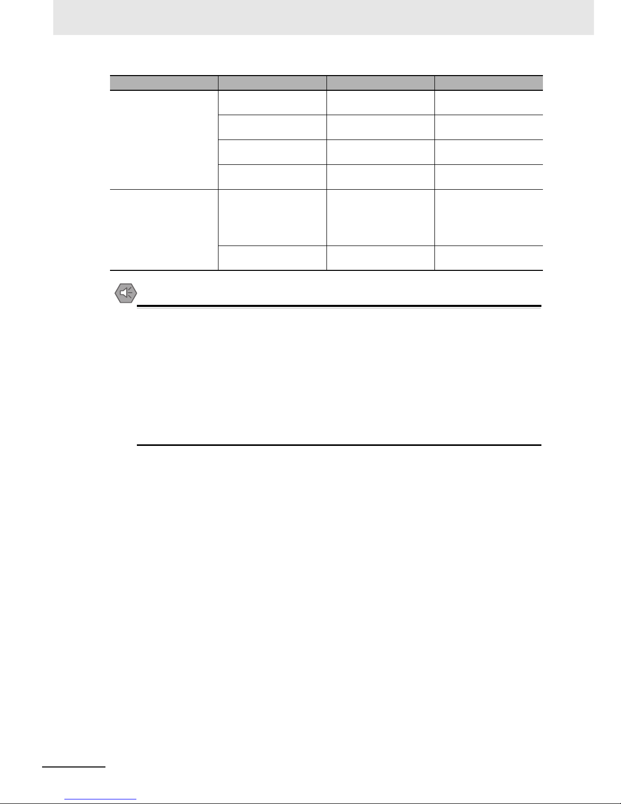
6 Maintenance and Troubleshooting
6-4
NB-series Programmable Terminals Startup Guide Manual(V109)
Precautions for Safe Use
• Customers may not replace the backlight lamp inside the NB Unit. Please contact OMRON’s
customer service center.
•
Deterioration over time can cause the touch points to move. Calibrate the touch panel periodically.
• Water and oil resistance will be lost if the front sheet is torn or is peeling off. Do not use the
Unit, if the front sheet is torn or is peeling off.
• Dispose of the Units and batteries according to local ordinances as they apply.
• Periodically check the installation conditions in applications where the PT is subject to contact
with oil or water.
• The rubber packing will deteriorate, shrink, or harden depending on the operating environment.
Inspect and replace the rubber packing periodically.
Installation state Looseness of fixing metal
pieces etc.
Specified torque Phillips screwdrivers
Connection state of
connector for the cable
Inserted fully and without
looseness.
Phillips screwdrivers
Looseness of screw for
external wiring
Without looseness Phillips screwdrivers
State of external
connection cable
Without abnormality such
as disconnection etc.
Visual check + multimeter
Object with expected life Backlight brightness With enough brightness
Backlight life: approx.
50,000 hours (Typ) at
room temperature (25 °C)
with 40% brightness.
Visual check
Battery 5 years (at 25 °C) Replace it every 5 years
once.
Checking Items Checking Contents Criterion Checking Method
Page 94

6-5
6 Maintenance and Troubleshooting
NB-series Programmable Terminals Startup Guide Manual(V109)
6-3 Troubleshooting
6
6-3-1 Software Trouble
6-3 Troubleshooting
This section describes troubleshooting measures when errors occur.
When a problem occurs during operation, refer to the listed problems below for the corresponding
solutions.
1
The condition of the USB driver for the HMI
If HMI cannot perform normal downloading/uploading, it’s usually because the USB driver is not
set up properly.
Setup Method:
During the process of the software setup, the PC will automatically prompt you to set up the
USB driver. You can choose the correct setup method according to the displayed information,
click the [Still Proceed] at the final step to complete the process. However, if the automatic setup
fails, you can still perform the setup manually. Connect the Unit and the PC with a USB cable,
energize the Unit, and a prompt to set up new hardware will pop up at the right bottom corner.
Following the displayed information, choose [Install from a list specific location (Advanced)], and
find the USB driver in the driver file of NB-Designer’s installation directory.
2
The NB-Designer software can run in XP/Vista/Win7 systems
It is compatible with XP, Vista and Win7 operating systems.
Pay attention to the following items when using Windows Vista/7:
(a) You must log in Vista/Win7 operating systems as the administrator.
(b) If you have compatibility problems when running the NB-Designer, run the software in
compatibility mode. Right-click the mouse on the icon “NB-Designer.exe” to select
compatible with Windows XP.
(c) When running the NB-Designer for the first time, right-click the mouse on the icon “NB-
Designer.exe” to select “Run this program as an administrator”. And then, run the
software directly.
6-3-1 Software Trouble
Page 95

6 Maintenance and Troubleshooting
6-6
NB-series Programmable Terminals Startup Guide Manual(V109)
3
How to change system parameters like user level passwords and Baud rate
These are all controlled by the local special register. These system parameters can be found by
double-clicking the component attributes, and selecting [System register].
For example, the addresses for changing the password online are: LW10022~10023 Password/0 level
Occupying a double word; LW10024~10025 Passowrd/1 level Occupying a double word;
LW10026~10027 Password/level 2 Occupying a double word; besides, LW10118~10143
Password/level 3~15 Occupying double word * 13. If the level 2 password needs to be changed, set in
the software as follows: First, place a Number Input component on window, check [System Register],
then select LW10026, as shown below
Page 96

6-7
6 Maintenance and Troubleshooting
NB-series Programmable Terminals Startup Guide Manual(V109)
6-3 Troubleshooting
6
6-3-1 Software Trouble
Select [Password] for the Data Type in the attributes page of [Numeric Data], as follows:
The process is the same for changing other system parameters online. But note that after changing the
following system parameters, the HMI needs to be rebooted to validate the changes.
System Parameter Setting: the following addresses will take effect after reboot.
Addresses Descriptions comments
10010 Initial Window number 0~65535
10011 Screen saver (backlight saver) 0 (OFF, Constant, Screen saver inactivated)
1~600 minutes (activated)
10013 Common window/Pop-up window 0: Normal
1: Higher than other windows
10014 Common window/attribute 0: Lower than the Base window
1: Higher than the Base window
10015 Storage event number 0~65535
10016 RTC source 0: PLC(Local Word)
1: Internal RTC
10017 Default language 0~3
10018 System reserve HMI internal use
Page 97

6 Maintenance and Troubleshooting
6-8
NB-series Programmable Terminals Startup Guide Manual(V109)
4
The difference between User permissions and User levels
User levels: there is a difference between high-level users and low-level users - high-level users
can access low-level windows, while low-level users can not access high-level windows. Whole
windows can be encrypted based on user levels.
User permissions: user permissions are not restricted by user levels. As long as the user’s
name and password are input correctly, the component which is set limited for access to it can
be operated. With the user permission, user accounts can be added or deleted. User
permissions only work on components, and have nothing to do with the window password.
5
What if the uploading password or the online change password of the HMI is lost
If the uploading password of HMI is lost, data cannot be uploaded, and the only solution is to
download the project again to overwrite the original one.
Similarly, if the online change password is lost, it also requires to download the project again
and set a new password.
Thus, in order to guarantee the safety of users’ projects, please back up the original projects,
for decryption is not within our service range.
6
Why cannot the system time be changed during offline simulation
Offline simulation uses the PC’s clock, therefore the time cannot be changed. It can only be
changed when downloaded to the HMI.
7
How to use the Operator Confirm function
When the user is fabricating a screen, some buttons may require a second confirmation to
validate the operation, and at this time, the Operator Confirm function can fit well here. This
function can control components. For example, you can check the [Operator Confirm] on the
[Control Setting] attributes page of the bit status setting component, as shown below:
A dialog box as follows will pop up once this option is checked:
Page 98

6-9
6 Maintenance and Troubleshooting
NB-series Programmable Terminals Startup Guide Manual(V109)
6-3 Troubleshooting
6
6-3-1 Software Trouble
8
When opening a project, what if there is a prompt: [Font not existing in the system]
For example: if attempting to open a project involving in a PC that does not incorporate
, a prompt [ does not exist] will pop up, as follows:
If this font issue is ignored, will be replaced with a font that exists in the system, eg.
UnBatang.
9
How to set the addresses of the component for displaying warnings and events, and how to
inquire warnings and events
It’s best to use the internal register of the HMI - LW for the address type of the component for
displaying warnings and events, and the address can be designated as any of the vacant
address in the project. When we record warnings and events on HMI, one page is almost
certainly not enough, then turn-page inquiring is needed to be set, thus the address in the
attributes of the component for displaying warnings and events takes effect. Take LW10 for an
example, as follows:
Page 99

6 Maintenance and Troubleshooting
6-10
NB-series Programmable Terminals Startup Guide Manual(V109)
Use two [Multi-State Setting Component] as the Page Up/Down button, designate the button
address the same as the component for display, and set as follows in the attributes page of
[Multi-State Setting].
Note Incremental upper limit is determined by how many events the customer wants to record, while the
decremental lower limit is recommended to be set to 0.
10
Why is there one event inquiring record less
When the customer set the [Multi-State Setting component] for Page Up/Down, the lower limit is
set to 1, which will cause the records to be one less. The correct setting is as follows:
Page 100

6-11
6 Maintenance and Troubleshooting
NB-series Programmable Terminals Startup Guide Manual(V109)
6-3 Troubleshooting
6
6-3-1 Software Trouble
11
How to keep the time in the event record and in the PLC synchronized
Check [Use The External Clock for Event] in [HMI Attribute] __ [HMI Extended Attributes], as
follows:
Meanwhile, clock register data inside the PLC is also needed to be transmitted to the local
register LW9010-9017. For details, refer to the NB-Designer User Manual [3-10-3 HMI
Extended Attributes].
12
Why cannot the history events be saved even if “saving” is selected
In most of this kind of cases, although the customer selects to save them, the No. of events to
be saved which is 0 by default is not changed to the No. the customer needs, thus the problem
occurs. In this case, just set the No. of events to be saved to make it work. This is done in [HMI
Attribute] --- [Historical Events Storage], as follows:
 Loading...