

Page 1

Programmable Terminal
NA-series
Hardware
User’s Manual
NA5-15101
NA5-12101
NA5-9001
NA5-7001
V117-E1-08
Page 2
NOTE
All rights reserved. No part of this publication may be reproduced, stored in a retrieval system, or transmitted, in
any form, or by any means, mechanical, electronic, photocopying, recording, or otherwise, without the prior
written permission of OMRON.
No patent liability is assumed with respect to the use of the information contained herein. Moreover, because
OMRON is constantly striving to improve its high-quality products, the information contained in this manual is
subject to change without notice. Every precaution has been taken in the preparation of this manual. Nevertheless, OMRON assumes no responsibility for errors or omissions. Neither is any liability assumed for damages
resulting from the use of the information contained in this publication.
Trademarks
• Sysmac and SYSMAC are trademarks or registered trademarks of OMRON Corporation in Japan and other
countries for OMRON factory automation products.
• Microsoft, Windows, Windows Vista, Excel, and Visual Basic are either registered trademarks or trademarks of
Microsoft Corporation in the United States and other countries.
• EtherCAT® is registered trademark and patented technology, licensed by Beckhoff Automation GmbH, Germany.
• ODVA, CIP, CompoNet, DeviceNet, and EtherNet/IP are trademarks of ODVA.
• The SD and SDHC logos are trademarks of SD-3C, LLC.
• Portions of this software are copyright 2014 The FreeType Project (www.freetype.org). All rights reserved.
Other company names and product names in this document are the trademarks or registered trademarks of their
respective companies.
Copyrights
Microsoft product screen shots reprinted with permission from Microsoft Corporation.
Page 3

Introduction
Thank you for purchasing an NA-series Programmable Terminal.
This manual contains information that is necessary to use the NA-series Programmable Terminal.
Please read this manual and make sure you understand the functionality and performance of the
NA-series Programmable Terminal before you attempt to use it in a control system.
Keep this manual in a safe place where it will be available for reference during operation.
Intended Audience
This manual is intended for the following personnel, who must also have knowledge of electrical systems (an electrical engineer or the equivalent).
• Personnel in charge of introducing FA systems.
• Personnel in charge of designing FA systems.
• Personnel in charge of installing and maintaining FA systems.
• Personnel in charge of managing FA systems and facilities.
Introduction
Applicable Products
This manual covers the following products.
• NA-series Programmable Terminals
*1. Unless otherwise specified, the descriptions for the NA5-W apply to the NA5-U as
well.
*1
NA-series Programmable Terminal Hardware User’s Manual (V117)
1
Page 4

Relevant Manuals
Relevant Manuals
The basic information required to use an NA-series PT is provided in the following three manuals.
• NA-series Programmable Terminal Hardware User’s Manual (Cat. No. V117)
• NA-series Programmable Terminal Software User’s Manual (Cat. No. V118)
• NA-series Programmable Terminal Device Connection User’s Manual (Cat. No. V119)
Operations are performed from the Sysmac Studio Automation Software.
Refer to the Sysmac Studio Version 1 Operation Manual (Cat. No. W504) for information on the Sys-
mac Studio.
Other manuals are necessary for specific system configurations and applications.
The following manual is also available to walk you through installations and operations up to starting
actual operation using simple examples.
Refer to it as required.
• NA-series Programmable Terminal Startup Guide Manual (Cat. No. V120)
2
NA-series Programmable Terminal Hardware User’s Manual (V117)
Page 5
Manual Structure
Level 1 heading
Level 2 heading
Level 3 heading
Level 2 heading
A step in a procedure
Manual name
Special information
Level 3 heading
Page tab
Give the current
headings.
Indicates a procedure.
Icons indicate precautions,
additional information, or
reference information.
Gives the number
of the main section.
3 - 5
3 Installation and Wiring
NA Series Programmable Terminal Hardware User’s Manual (V117)
3-3 Installing NA-series PTs
3
3-3-1 Installation in a Control Panel
3-3 Installing NA-series PTs
The NA-series PT is installed by embedding it in a control panel. Panel Mounting Brackets and a Phillips screwdriver are
required to mount the NA-series PT. The required number of Panel Mounting Brackets are included with the NA-series PT.
Use the following installation procedure.
1 Open a hole in which to embed the NA-series PT with the following dimensions and insert the
NA-series PT from the front side of the panel.
Additional Information
You can use an NS-USBEXT-1M USB Relay Cable to extend the USB slave connector on the
back panel of the NA-series PT to the front surface of a control panel. If you use the USB Relay
Cable, open a hole with the following dimensions and install the Cable.
2 Attach the panel mounting brackets from the back of the panel as shown in the following figure.
The number of mounting brackets depends on the size of the NA-series PT, as shown in the following
table. Refer to Bracket Mounting Locations for Different NA-series PT Sizes on page 3-8, below.
Catch the brackets in the mounting holes in the NA-series PT, pull forward lightly, and then use
a Phillips screwdriver to tighten the screws and secure the NA-series PT to the panel, which will
be held between the mounting brackets and the NA-series PT.
3-3-1 Installation in a Control Panel
Installation in a Control Panel
Model Dimensions
NA5-15W
392
+1/-0
× 268
+1/-0
mm (horizontal × vertical)
NA5-12W
310
+1/-0
× 221
+1/-0
mm (horizontal × vertical)
NA5-9W
261
+1/-0
× 166
+1/-0
mm (horizontal × vertical)
NA5-7W
197
+ 0.5/-0
× 141
+0.5/-0
mm (horizontal × vertical)
Model Number of Panel Mounting Brackets
NA5-15W 8 locations
NA5-12W 6 locations
NA5-9W 4 locations
NA5-7W 4 locations
Panel Mounting Bracket Phillips screwdriver
Vertical
Horizontal
Recommended panel thickness: 1.6 to 6.0 mm
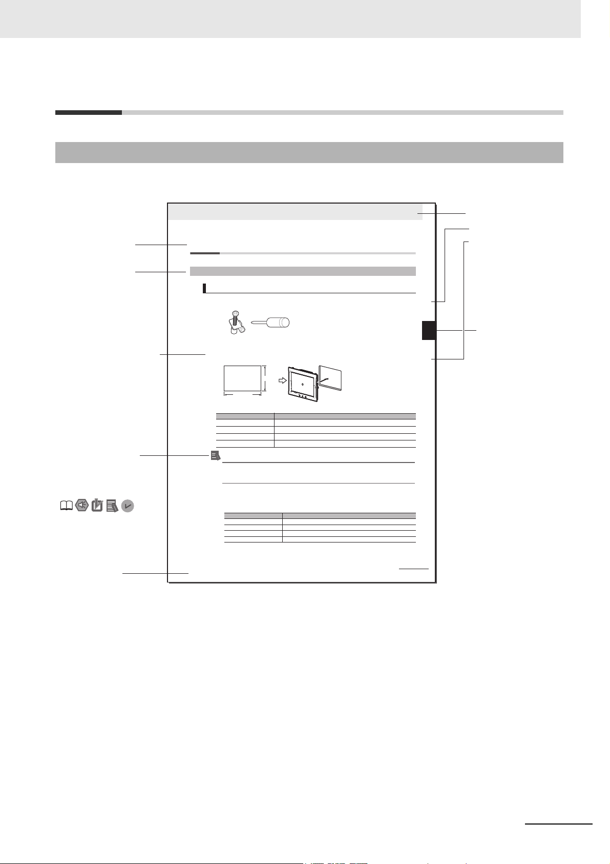
Page Structure and Markings
The following page structure is used in this manual.
Manual Structure
NA-series Programmable Terminal Hardware User’s Manual (V117)
Note This illustration is provided only as a sample. It may not literally appear in this manual.
3
Page 6
Manual Structure
Precautions for Safe Use
Precautions for Correct Use
Additional Information
Version Information
Special Information
Special information in this manual is classified as follows:
Precautions on what to do and what not to do to ensure safe usage of the product.
Indicates precautions on what to do and what not to do to ensure proper operation and performance.
Additional information to read as required.
This information is provided to increase understanding or make operation easier.
Information on differences in specifications and functionality with different versions is given.
4
NA-series Programmable Terminal Hardware User’s Manual (V117)
Page 7
Appendices
Troubleshooting
Maintenance
System Program
Installation and Wiring
Configuration Units
Introduction to the NA-series Programmable Terminals
1
2
3
4
5
6
1
2
3
4
6
5
A
A
I
I
Index
Sections in this Manual
Sections in this Manual
NA-series Programmable Terminal Hardware User’s Manual (V117)
5
Page 8

Sections in this Manual
6
NA-series Programmable Terminal Hardware User’s Manual (V117)
Page 9

CONTENTS
Introduction .............................................................................................................. 1
Relevant Manuals..................................................................................................... 2
Manual Structure...................................................................................................... 3
Sections in this Manual........................................................................................... 5
Terms and Conditions Agreement ........................................................................11
Safety Precautions................................................................................................. 13
Precautions for Safe Use ...................................................................................... 15
Precautions for Correct Use ................................................................................. 18
CONTENTS
Regulations and Standards .................................................................................. 19
Conformance to Shipbuilding Standards ............................................................ 21
Related Manuals..................................................................................................... 23
Terminology............................................................................................................ 29
Revision History..................................................................................................... 30
Section 1 Introduction to the NA-series Programmable Terminals
1-1 NA-series Programmable Terminals.................................................................................... 1-2
1-1-1 Features...................................................................................................................................... 1-2
1-2 System Configurations ......................................................................................................... 1-4
1-2-1 Connecting to the Support Software........................................................................................... 1-4
1-2-2 Network Configuration with Other Devices................................................................................. 1-4
1-3 Available Products ................................................................................................................ 1-5
1-3-1 NA Units...................................................................................................................................... 1-5
1-3-2 Support Software........................................................................................................................ 1-5
1-3-3 Other Optional Products ............................................................................................................. 1-6
1-4 Specifications ........................................................................................................................ 1-7
1-4-1 General Specifications................................................................................................................ 1-7
1-4-2 Performance Specifications...................................................................................................... 1-10
Section 2 Configuration Units
2-1 NA Units ................................................................................................................................. 2-2
2-1-1 Components and Functions........................................................................................................ 2-2
2-2 SD Memory Cards.................................................................................................................. 2-9
2-2-1 Models and Specifications.......................................................................................................... 2-9
2-2-2 Applications ................................................................................................................................ 2-9
2-2-3 Installing and Removing ............................................................................................................. 2-9
NA-series Programmable Terminal Hardware User’s Manual (V117)
7
Page 10

CONTENTS
2-3 USB Memory Devices..........................................................................................................2-11
2-3-1 Models and Specifications ........................................................................................................ 2-11
2-3-2 Applications ............................................................................................................................... 2-11
2-3-3 Installing and Removing ............................................................................................................ 2-11
2-4 Support Software................................................................................................................. 2-13
2-4-1 Connection Methods .................................................................................................................2-13
Section 3 Installation and Wiring
3-1 Processing at Power ON and Power OFF ........................................................................... 3-2
3-1-1 Power ON Operation...................................................................................................................3-2
3-1-2 Power OFF Operation .................................................................................................................3-2
3-2 Fail-safe Measures ................................................................................................................ 3-3
3-2-1 Power ON Sequence ..................................................................................................................3-3
3-3 Installing NA Units................................................................................................................. 3-4
3-3-1 Installation in a Control Panel .....................................................................................................3-4
3-4 Wiring Methods...................................................................................................................... 3-9
3-4-1 Power Supply Wiring...................................................................................................................3-9
3-4-2 Wiring the Ethernet Port............................................................................................................3-13
3-4-3 Wiring the Serial Port ................................................................................................................3-13
3-5 Control Panel Installation ................................................................................................... 3-14
3-5-1 Temperature..............................................................................................................................3-14
3-5-2 Humidity ....................................................................................................................................3-15
3-5-3 Vibration and Shock ..................................................................................................................3-16
3-5-4 Atmosphere ...............................................................................................................................3-16
3-5-5 Electrical Environment ..............................................................................................................3-17
3-5-6 Grounding ................................................................................................................................. 3-19
Section 4 System Program
4-1 System Program and NA Unit Startup Status ..................................................................... 4-2
4-2 System Recovery................................................................................................................... 4-3
4-3 System Menu Overview ........................................................................................................4-6
4-3-1 System Menu Configuration ........................................................................................................4-6
4-3-2 Using the System Menu ..............................................................................................................4-9
4-4 System Menu Details........................................................................................................... 4-11
4-4-1 Display Settings (Project System Menu)................................................................................... 4-11
4-4-2 Language Settings (Project System Menu)...............................................................................4-12
4-4-3 External Device Settings (Project System Menu) .....................................................................4-12
4-4-4 User Accounts (Project System Menu) .....................................................................................4-13
4-4-5 NJ/NX/NY Troubleshooter (Project System Menu) ...................................................................4-14
4-4-6 Alarm Viewer (Project System Menu) .......................................................................................4-26
4-4-7 Project System Menu Settings (Project System Menu) ............................................................4-28
4-4-8 Print Settings (Project System Menu) .......................................................................................4-28
4-4-9 Buzzer Settings (Project System Menu) ...................................................................................4-29
4-4-10 Date & Time Settings (Device System Menu)........................................................................... 4-30
4-4-11 Language Settings (Device System Menu)...............................................................................4-30
4-4-12 Interface Settings (Device System Menu).................................................................................4-31
4-4-13 Brightness Settings (Device System Menu)..............................................................................4-36
4-4-14 Transfer Operations (Device System Menu)............................................................................. 4-37
4-4-15 Hardware Diagnostics (Device System Menu).......................................................................... 4-42
4-4-16 Production Information (Device System Menu)......................................................................... 4-45
8
NA-series Programmable Terminal Hardware User’s Manual (V117)
Page 11

Section 5 Troubleshooting
5-1 Operation after an Error........................................................................................................ 5-2
5-1-1 Checking NA Unit Status ............................................................................................................ 5-2
5-1-2 Fatal Errors in the NA Unit.......................................................................................................... 5-2
5-1-3 Nonfatal Errors in the NA Unit .................................................................................................... 5-3
5-2 Troubleshooting .................................................................................................................... 5-4
5-2-1 Confirming NA Unit Operation .................................................................................................... 5-4
5-2-2 Correcting Fatal Errors in the NA Unit ........................................................................................ 5-4
5-2-3 Troubleshooting Non-fatal Errors................................................................................................ 5-5
5-2-4 Causes and Correction When You Cannot Go Online from the Sysmac Studio......................... 5-5
5-2-5 Troubleshooting NA Unit Errors.................................................................................................. 5-9
Section 6 Maintenance
6-1 Periodic Maintenance and Inspection ................................................................................. 6-2
6-1-1 Preparations for Problems.......................................................................................................... 6-2
6-1-2 Periodic Inspection ..................................................................................................................... 6-2
6-1-3 Precautions When Replacing the NA Unit .................................................................................. 6-4
6-1-4 Cleaning...................................................................................................................................... 6-4
6-2 Replacing the Battery............................................................................................................ 6-5
6-2-1 Battery Replacement .................................................................................................................. 6-5
6-2-2 Operation without a Battery ........................................................................................................ 6-6
CONTENTS
Appendices
A-1 Dimensions ............................................................................................................................A-2
A-2 Available Products ................................................................................................................A-6
Index
A-1-1 NA Units......................................................................................................................................A-2
A-2-1 Optional Products ....................................................................................................................... A-6
NA-series Programmable Terminal Hardware User’s Manual (V117)
9
Page 12

CONTENTS
10
NA-series Programmable Terminal Hardware User’s Manual (V117)
Page 13

Terms and Conditions Agreement
Terms and Conditions Agreement
Warranty, Limitations of Liability
Warranties
Exclusive Warranty
Omron’s exclusive warranty is that the Products will be free from defects in materials and workmanship for a period of twelve months from the date of sale by Omron (or such other period expressed in
writing by Omron). Omron disclaims all other warranties, express or implied.
Limitations
OMRON MAKES NO WARRANTY OR REPRESENTATION, EXPRESS OR IMPLIED, ABOUT
NON-INFRINGEMENT, MERCHANTABILITY OR FITNESS FOR A PARTICULAR PURPOSE OF
THE PRODUCTS. BUYER ACKNOWLEDGES THAT IT ALONE HAS DETERMINED THAT THE
PRODUCTS WILL SUITABLY MEET THE REQUIREMENTS OF THEIR INTENDED USE.
Omron further disclaims all warranties and responsibility of any type for claims or expenses based
on infringement by the Products or otherwise of any intellectual property right.
Buyer Remedy
Omron’s sole obligation hereunder shall be, at Omron’s election, to (i) replace (in the form originally
shipped with Buyer responsible for labor charges for removal or replacement thereof) the non-complying Product, (ii) repair the non-complying Product, or (iii) repay or credit Buyer an amount equal
to the purchase price of the non-complying Product; provided that in no event shall Omron be
responsible for warranty, repair, indemnity or any other claims or expenses regarding the Products
unless Omron’s analysis confirms that the Products were properly handled, stored, installed and
maintained and not subject to contamination, abuse, misuse or inappropriate modification. Return of
any Products by Buyer must be approved in writing by Omron before shipment. Omron Companies
shall not be liable for the suitability or unsuitability or the results from the use of Products in combination with any electrical or electronic components, circuits, system assemblies or any other materials or substances or environments. Any advice, recommendations or information given orally or in
writing, are not to be construed as an amendment or addition to the above warranty.
See http://www.omron.com/global/ or contact your Omron representative for published information.
Limitation on Liability; Etc
OMRON COMPANIES SHALL NOT BE LIABLE FOR SPECIAL, INDIRECT, INCIDENTAL, OR CONSEQUENTIAL DAMAGES, LOSS OF PROFITS OR PRODUCTION OR COMMERCIAL LOSS IN ANY
WAY CONNECTED WITH THE PRODUCTS, WHETHER SUCH CLAIM IS BASED IN CONTRACT,
WARRANTY, NEGLIGENCE OR STRICT LIABILITY.
Further, in no event shall liability of Omron Companies exceed the individual price of the Product on
which liability is asserted.
NA-series Programmable Terminal Hardware User’s Manual (V117)
11
Page 14

Terms and Conditions Agreement
Application Considerations
Suitability of Use
Omron Companies shall not be responsible for conformity with any standards, codes or regulations
which apply to the combination of the Product in the Buyer’s application or use of the Product. At
Buyer’s request, Omron will provide applicable third party certification documents identifying ratings
and limitations of use which apply to the Product. This information by itself is not sufficient for a complete determination of the suitability of the Product in combination with the end product, machine, system, or other application or use. Buyer shall be solely responsible for determining appropriateness of
the particular Product with respect to Buyer’s application, product or system. Buyer shall take application responsibility in all cases.
NEVER USE THE PRODUCT FOR AN APPLICATION INVOLVING SERIOUS RISK TO LIFE OR
PROPERTY WITHOUT ENSURING THAT THE SYSTEM AS A WHOLE HAS BEEN DESIGNED TO
ADDRESS THE RISKS, AND THAT THE OMRON PRODUCT(S) IS PROPERLY RATED AND
INSTALLED FOR THE INTENDED USE WITHIN THE OVERALL EQUIPMENT OR SYSTEM.
Programmable Products
Omron Companies shall not be responsible for the user’s programming of a programmable Product, or
any consequence thereof.
Disclaimers
Performance Data
Data presented in Omron Company websites, catalogs and other materials is provided as a guide for
the user in determining suitability and does not constitute a warranty. It may represent the result of
Omron’s test conditions, and the user must correlate it to actual application requirements. Actual performance is subject to the Omron’s Warranty and Limitations of Liability.
Change in Specifications
Product specifications and accessories may be changed at any time based on improvements and other
reasons. It is our practice to change part numbers when published ratings or features are changed, or
when significant construction changes are made. However, some specifications of the Product may be
changed without any notice. When in doubt, special part numbers may be assigned to fix or establish
key specifications for your application. Please consult with your Omron’s representative at any time to
confirm actual specifications of purchased Product.
12
Errors and Omissions
Information presented by Omron Companies has been checked and is believed to be accurate; however, no responsibility is assumed for clerical, typographical or proofreading errors or omissions.
NA-series Programmable Terminal Hardware User’s Manual (V117)
Page 15

Safety Precautions
Indicates a potentially hazardous situation which, if
not avoided, could result in mild or moderate injury or
at the worst, serious injury or death. Additionally,
there may be severe property damage.
Indicates a potentially hazardous situation which, if not
avoided, may result in minor or moderate injury, or
property damage.
Definition of Precautionary Information
The following notation is used in this manual to provide precautions required to ensure safe usage of
the NA-series Programmable Terminal. The safety precautions that are provided are extremely important to safety. Always read and heed the information provided in all safety precautions.
The following notation is used.
WARNING
Safety Precautions
Indicates precautions on what to do and what not to do to ensure safe usage of the product.
Indicates precautions on what to do and what not to do to ensure proper operation and performance.
Symbols
Caution
Precautions for Safe Use
Precautions for Correct Use
The circle and slash symbol indicates operations that you must not do.
The specific operation is shown in the circle and explained in text.
This example indicates prohibiting disassembly.
The triangle symbol indicates precautions (including warnings).
The specific operation is shown in the triangle and explained in text.
This example indicates a general precaution.
NA-series Programmable Terminal Hardware User’s Manual (V117)
13
Page 16

Safety Precautions
WARNING
Warnings
Do not attempt to take the NA Unit apart and do not touch the product inside while the
power is being supplied. Otherwise it may result in electric shock.
Always ensure that the personnel in charge confirm that installation, inspection, and
maintenance were properly performed for the NA Unit. “Personnel in charge” refers to
individuals qualified and responsible for ensuring safety during machine design,
installation, operation, maintenance, and disposal.
Ensure that installation and post-installation checks are performed by personnel in charge
who possess a thorough understanding of the machinery to be installed.
Do not use the input functions such as the touch panel or function keys of the NA Unit, in
applications that involve human life, in applications that may result in serious injury, or for
emergency stop switches.
Do not attempt to disassemble, repair, or modify the NA Unit. It may cause NA Unit to lose
its safety function.
Never press two points or more on the touch panel of the NA Unit at a time. Touching two
points or more interrupts normal touch panel operations.
To conform to UL Type 4X standards, always use the NA5-W with a
High-pressure Waterproof Attachment (PWA). If you do not use a PWA, there is a risk of
water entry, which may cause severe equipment damage.
Always pay attention to the inside dimensions when you mount a PWA on the
NA5-W. If you do not mount the PWA correctly, there is a risk of water entry,
which may cause severe equipment damage.
14
NA-series Programmable Terminal Hardware User’s Manual (V117)
Page 17
Precautions for Safe Use
Back of the case
DIP switch
Correct technique
Incorrect technique
• When unpacking the NA Unit, check carefully for any external scratches or other damages. Also,
shake the NA Unit gently and check for any abnormal sound.
• The NA Unit must be installed in a control panel.
• To conform to UL Type 1 standards, the mounting panel thickness must be 1.6 to 6.0 mm.
To conform to UL Type 4X standards, the thickness must be 1.6 to 4.5 mm.
To conform to UL Type 4X standards, always use the NA5-W with a High-pressure
Waterproof Attachment (PWA). If you do not use a PWA, there is a risk of water entry, which may
cause severe equipment damage. Do not use the NA Unit outdoors. Tighten the Mounting Brackets
evenly to a torque of between 0.5 and 0.6 N·m to maintain water and dust resistance. If the tightening
torque exceeds the specified value, or the tightening is not even, deformation of the front panel may
occur. What is more, make sure the panel is not dirty or warped, that the front surface is smooth, and
that the panel is strong enough to hold the NA Unit.
• Do not let metal particles enter the NA Unit when preparing the panel.
• Turn OFF the power supply before connecting or disconnecting cables.
• Periodically check the installation conditions in applications where the NA Unit is subject to contact
with oil or water.
• Be certain to use the cables with lock mechanism such as serial cable or the Ethernet cable after
confirming if it is securely locked.
• Do not touch the packaging part of the circuit board with your bare hands. Discharge any static electricity from your body before handling the board.
• Do not use volatile solvents such as benzene and thinners or chemical cloths.
• Water and oil resistance will be lost if the front sheet is torn or is peeling off. Do not use the NA Unit,
if the front sheet is torn or is peeling off.
• As the rubber packing will deteriorate, shrink, or harden depending on the operating environment,
periodical inspection is necessary.
• Confirm the safety of the system before turning ON or OFF the power supply, or pressing the reset
switch.
• The whole system may stop depending on how the power supply is turned ON or OFF. Turn ON/OFF
the power supply according to the specified procedure.
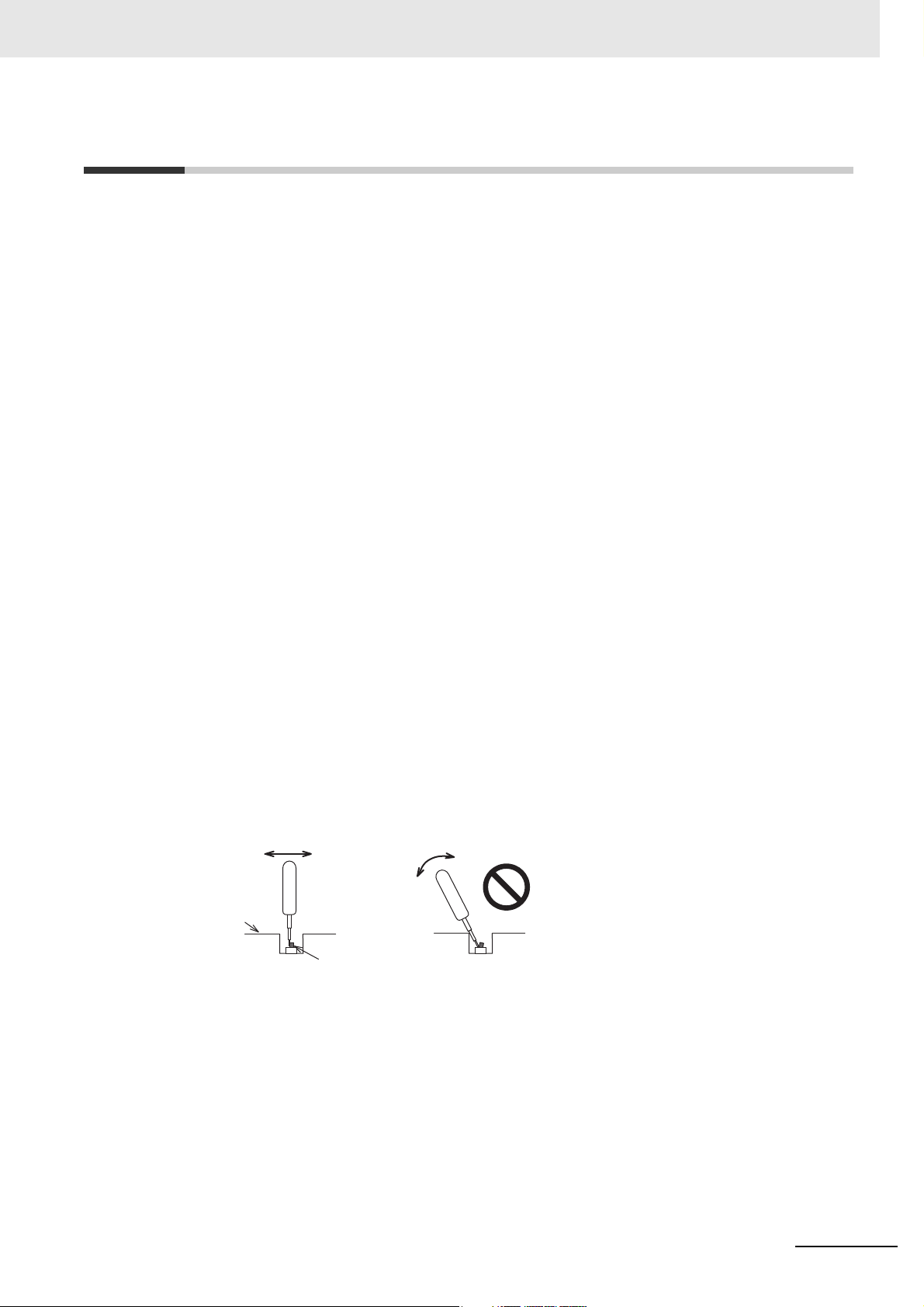
• Operate DIP switch according to the following way.
Precautions for Safe Use
NA-series Programmable Terminal Hardware User’s Manual (V117)
The DIP switch may break if it is levered with a tool against the case as shown in the figure.
• Once the DIP switch settings are changed, reset by pressing the reset switch, or restart the power
supply.
• Initialize the project, after confirming that existing project is backed up at the Sysmac Studio.
• When changing the password, do not reset or turn OFF the power supply until the writing is completed. A failure to store the password may cause the project to fail to function.
• While uploading or downloading a project or a system program, do not perform the operations as follows. Such operations may corrupt the project or the system program:
• Turning OFF the power supply of the NA Unit.
• Resetting the NA Unit.
• Removing the USB devices or SD card.
15
Page 18
Precautions for Safe Use
• Disconnecting the cable between a support tool and the NA Unit.
• Do not connect an AC power supply to the DC power terminals.
• Do not perform a dielectric strength test.
• Use a DC power with a slight voltage fluctuation and that will provide a stable output even if the input
is momentarily interrupted for 10 ms. Also use the one with reinforced insulation or double insulation.
Rated Power Supply Voltage: 24VDC (Allowable range 19.2 to 28.8VDC)
• Use a power cable with AWG#12 to #22 thick (0.35mm2 to 3.31mm2). Peel the coating 7mm length
and tighten the terminal screw with the torque in the range of 0.5 to 0.6 N·m. Also confirm if the terminal screw is tighten appropriately.
• To prevent malfunctions caused by noise, ground the NA Unit correctly.
• Do not use any battery if strong impact is applied to it (e.g. by dropping on the floor) because such a
battery may cause a leakage.
• Confirm the type of the battery to install the battery properly.
• Apply power for at least five minutes before changing the battery. Mount a new battery within five
minutes after turning OFF the power supply. If power is not supplied for at least five minutes, the
clock data may be lost. Check the clock data after changing the battery.
• Do not dismantle a battery nor let it short-circuit.
• Do not apply an impact with the lithium battery, charge it, dispose it into a fire, or heat it. Doing either
of them may cause an ignition or a bursting.
• Dispose of the NA Units and batteries according to local ordinances as they apply.
• The following precaution must be displayed on all products containing lithium primary batteries with a
perchlorate content of 6ppb or higher when exporting them to or shipping them through California,
USA.
Perchlorate Material - special handling may apply.
See www.dtsc.ca.gov/hazardouswaste/perchlorate
The NA-Series contains a lithium primary battery with a perchlorate content of 6ppb or higher. When
exporting a product containing the NA-Series to or shipping such a product through California, USA,
label all packing and shipping containers appropriately.
• Do not connect the USB devices in the environment subject to the strong vibration.
• Do not connect USB devices which are not allowed to connect to NA Unit.
• Start actual system application only after checking normal operation of the system including storage
devices such as USB memory and SD card.
• When connecting peripheral devices which do not meet the performance level of the NA Unit for
noise and static electricity, ensure sufficient countermeasures against noise and static electricity during installation of the peripheral devices to the NA Unit.
• Do not carry out the following operations when accessing USB devices or SD card:
• Turning OFF the power supply of the NA Unit
• Press the Reset switch of the NA Unit
• Pull out the USB devices or SD card
• When using the No. 6 pin of the serial port connector for a voltage of DC+5V, make sure the supply
equipment's current capacity is below 250mA before using it. The DC+5V voltage output of the NA
Unit is +5V±5%, and the maximum current is 250mA.
sure to incorporate a program that call periodically signals dur-
• To ensure the system's safety, mak
ing the operation at connected device side and can confirm the normal functionality of the NA Unit
before running the system.
• Start actual system application only after sufficiently checking project, subroutine and the operation of
the program at the connected device side.
• To execute a subroutine with multiple threads, fully check the operation of the program that takes
multithreads into consideration, before starting actual system application.
e
16
NA-series Programmable Terminal Hardware User’s Manual (V117)
Page 19

Precautions for Safe Use
• To use numeric input functions safely, always make maximum and minimum limit settings.
• Do not press the touch panel with a force greater than 30 N.
• Do not use hard or pointed objects to operate or scrub the screen, otherwise the surface of the
screen may be damaged.
• The deterioration over time may cause the touch points to move on the touch panel. Calibrate the
touch panel periodically.
• A touch position detection error of approximately 20 pixels may occur due to the precision of the
touch panel. Always take this into account when positioning objects on the panel so adjoining objects
will not be activated by mistake.
• Confirm the safety of the system before pressing the touch panel.
• Do not accidentally press the touch panel when the backlight is not lit or when the display does not
appear or is too dark to identify visually.
• You can change the brightness by changing the setting such as in the system menu or by downloading project.
If the brightness is set to very dark, it causes flickering or unreadable screen. Additionally, the brightness can be restored by transferring the project again after setting the property of the brightness
appropriately.
In a case of the applications where end users can control the brightness, create the applications so
as keeping on operations by such as assigning the function which restores the brightness to one of
function keys, if necessary.
• Signals from the touch panel may not be entered if the touch panel is pressed consecutively at high
speed. Make sure to go on the next operation after confirming that the NA Unit has detected the input
of the touch panel.
• The function keys have the restrictions as follows:
• When you use gloves or others, the function keys may not work correctly depending on the material and thickness of the gloves. Take actual conditions of the gloves usage into considerations
prior to the system startup to perform the confirmation.
• The function keys do not work when covered with water. Remove the water completely before
use.
NA-series Programmable Terminal Hardware User’s Manual (V117)
17
Page 20

Precautions for Correct Use
Precautions for Correct Use
Do not install or store the NA Unit in any of the following locations:
• Locations subject to severe changes in temperature
• Locations subject to temperatures or humidity outside the range specified in the specifications
• Locations subject to condensation as the result of high humidity
• Locations subject to corrosive or flammable gases
• Locations subject to strong shock or vibration
• Locations outdoors subject to direct wind and rain
• Locations subject to strong ultraviolet light
• Locations subject to dust
• Locations subject to direct sunlight
• Locations subject to splashing oil or chemicals
Take appropriate and sufficient countermeasures when installing systems in
the following locations:
• Locations subject to static electricity or other forms of noise
• Locations subject to strong electric field or magnetic field
• Locations close to power supply lines
• Locations subject to possible exposure to radioactivity
Mounting Panel
• To conform to UL Type 1 standards, the mounting panel thickness must be 1.6 to 6.0 mm.
• To conform to UL Type 4X standards, the thickness must be 1.6 to 4.5 mm.
To conform to UL Type 4X standards, always use the NA5-W with a High-pressure
Waterproof Attachment (PWA). If you do not use a PWA, there is a risk of water entry, which may
cause severe equipment damage.
• Tighten the Mounting Brackets evenly to a torque of between 0.5 and 0.6 N·m to maintain water
and dust resistance. If the tightening torque exceeds the specified range or the tightening is not
even, deformation of the front panel may occur. Make sure the panel is not dirty or warped, that
the front surface is smooth, and that the panel is strong enough to hold the NA Unit.
18
NA-series Programmable Terminal Hardware User’s Manual (V117)
Page 21

Regulations and Standards
Conformance to EC Directives
Applicable Directives
• EMC Directive
Concepts
EMC Directive
OMRON devices that comply with EC Directives also conform to the related EMC standards so that
they can be more easily built into other devices or the overall machine. The actual products have
been checked for conformity to EMC standards.*
Whether the products conform to the standards in the system used by the customer, however, must
be checked by the customer. EMC-related performance of the OMRON devices that comply with EC
Directives will vary depending on the configuration, wiring, and other conditions of the equipment or
control panel on which the OMRON devices are installed. The customer must, therefore, perform
the final check to confirm that devices and the overall machine conform to EMC standards.
* Applicable EMC (Electromagnetic Compatibility) standards are as follows:
EMS (Electromagnetic Susceptibility): EN 61131-2:2007
EMI (Electromagnetic Interference): EN 61131-2:2007
Regulations and Standards
Conformance to EC Directives
The NA-series PTs comply with EC Directives. To ensure that the machine or device in which the
NA-series PT is used complies with EC Directives, the NA-series PT must be installed as follows:
• The NA Unit must be installed in a control panel.
• You must use reinforced insulation or double insulation for the DC power supplies connected to
the NA Unit.
• NA-series PTs that comply with EC Directives also conform to the Common Emission Standard
(EN 61000-6-4). Radiated emission characteristics (10-m regulations) may vary depending on the
configuration of the control panel used, other devices connected to the control panel, wiring, and
other conditions.
You must therefore confirm that the overall machine or equipment complies with EC Directives.
• This is a Class A product (for industrial environments). In a residential environment, it may cause
radio interference, in which case the user may be required to take appropriate measures.
NA-series Programmable Terminal Hardware User’s Manual (V117)
19
Page 22

Regulations and Standards
Conformance to KC Standards
Observe the following precaution if you use NA-series PTs in Korea.
Class A Device (Broadcasting Communications Device for Business Use)
This device obtained EMC registration for office use (Class A), and it is intended to be used in places
other than homes. Sellers and/or users need to take note of this.
20
NA-series Programmable Terminal Hardware User’s Manual (V117)
Page 23
Conformance to Shipbuilding Standards
Conformance to Shipbuilding Standards
The NA-series Programmable Terminals comply with shipping standards. Application conditions are set
for compliance for individual shipping standards, and it may not be possible to use the product in some
installation locations. Contact an OMRON sales representative before using the product.
International Shipping Standards
Shipping Standards of Various Countries
Abbreviation Country Name
NK Japan Nippon Kaiji Kyokai
LR Great Britain Lloyd’s Register of Shipping
DNV Norway Det Norske Veritas
RINA Italy Registro Italiano Navale
BV France Bureau Veritas
GL Germany Germanischer Lloyd
ABS USA American Bureau of Shipping
KR South Korea Korean Register of Shipping
CR Taiwan China Corporation Register of Shipping
Certification Status for NA Units
The following table shows the certification status with shipping standards for NA Units as of October
2015.
Abbreviation NA5W-15 NA5W-12 NA5W-9 NA5W-7
NK Certified Certified Certified Certified
LR Certified Certified Certified Certified
DNV Certified Certified Certified Certified
RINA Uncertified Uncertified Uncertified Uncertified
BV Uncertified Uncertified Uncertified Uncertified
GL Uncertified Uncertified Uncertified Uncertified
ABS Uncertified Uncertified Uncertified Uncertified
KR Uncertified Uncertified Uncertified Uncertified
CR Uncertified Uncertified Uncertified Uncertified
Abbreviation NA5-15U NA5-12U NA5-9U NA5-7U
NK
LR Certified Certified Certified Certified
DNV
RINA Uncertified Uncertified Uncertified Uncertified
BV Uncertified Uncertified Uncertified Uncertified
GL Uncertified Uncertified Uncertified Uncertified
ABS Uncertified Uncertified Uncertified Uncertified
KR Uncertified Uncertified Uncertified Uncertified
CR Uncertified Uncertified Uncertified Uncertified
*1. The criteria in the relevant standards have been met but certification is pending.
Uncertified
Uncertified
*1
*1
Uncertified
Uncertified
*1
*1
Uncertified
Uncertified
*1
*1
Uncertified
Uncertified
*1
*1
NA-series Programmable Terminal Hardware User’s Manual (V117)
21
Page 24
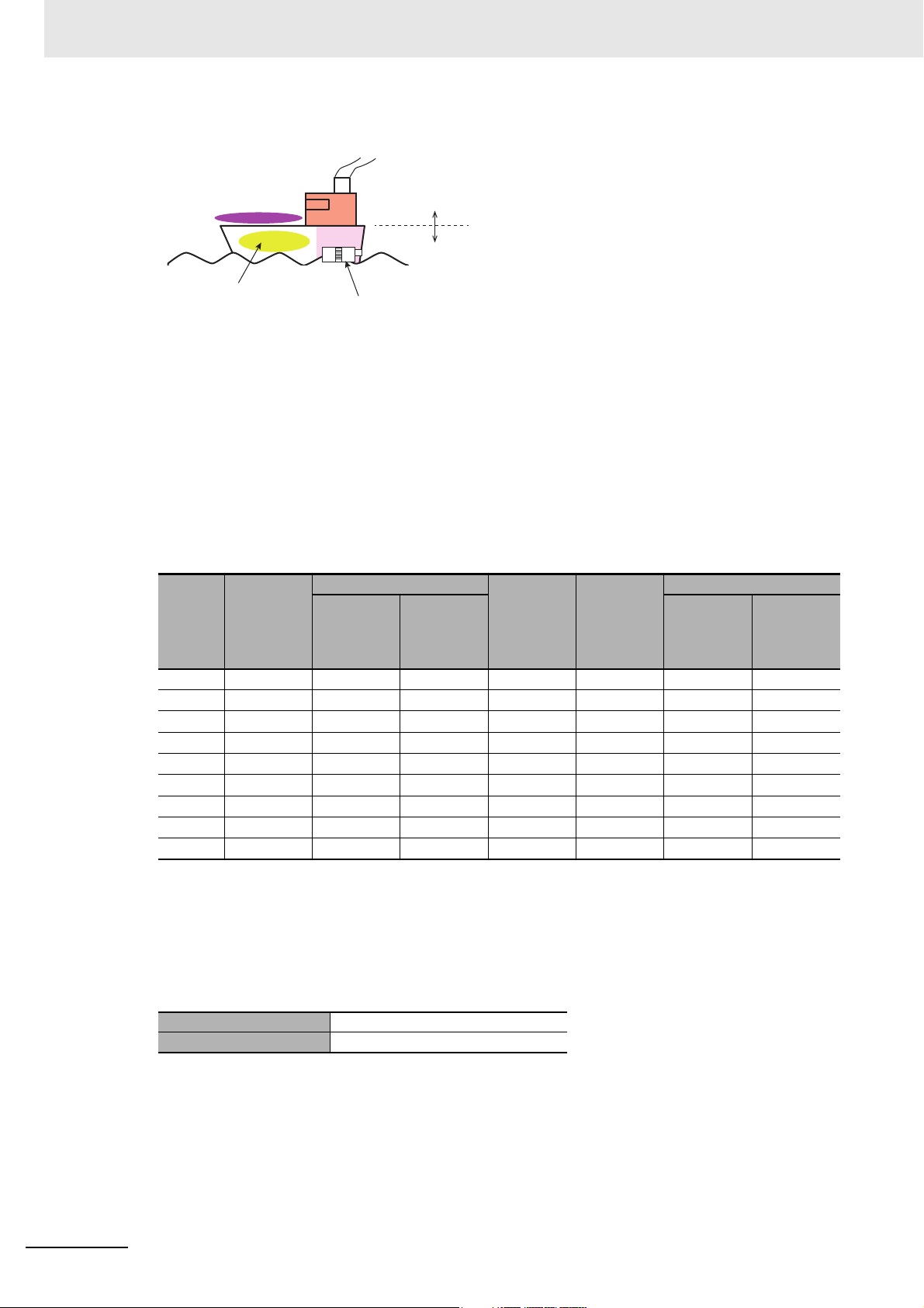
Conformance to Shipbuilding Standards
a. Deck
d. Engine room
Ocean
Devices on deck or bridge
Devices not on deck or bridge
e. Boiler room
Air conditioning
No air conditioning
b. Bridge
Air conditioning
No air conditioning
c. Depends on ship type
Emergency power supply devices on
bulk carrier ships carrying liquefied
gas or hazardous chemicals
Certification Zones for Shipping Standards
a. Deck zone
b. Zones with and without air conditioning on the bridge (e.g., helm room)
c. Depends on the ship type. Emergency power supply devices on bulk carrier ships carrying lique-
fied gas or hazardous chemicals.
d. Engine room zone (devices mounted on machinery that has strict vibration conditions, such as
diesel engines or air compressors)
e. Zones with and without air conditioning not on the bridge or deck (e.g., boiler room)
NA Unit Certification Zones for Shipping Standards
Stan-
dards
NK
LR
DNV
RINA
BV
GL
ABS
KR
CR
b. Bridge c. Ship
a. Deck
Uncertified Certified
Uncertified Certified Certified Uncertified Uncertified Certified Certified
Uncertified Certified Certified Uncertified Uncertified Certified Certified
Uncertified Uncertified Uncertified Uncertified Uncertified Uncertified Uncertified
Uncertified Uncertified Uncertified Uncertified Uncertified Uncertified Uncertified
Uncertified Uncertified Uncertified Uncertified Uncertified Uncertified Uncertified
Uncertified Uncertified Uncertified Uncertified Uncertified Uncertified Uncertified
Uncertified Uncertified Uncertified Uncertified Uncertified Uncertified Uncertified
Uncertified Uncertified Uncertified Uncertified Uncertified Uncertified Uncertified
No air con-
ditioning
With air
condition-
ing
Certified
type (e.g.,
bulk ship
with lique-
fied gas)
Uncertified Uncertified Certified Certified
d. E ngi ne
(e.g.)
e. Not on deck or bridge
No air con-
ditioning
Precautions for Compliance with Shipping Standards
1. Always install the NA Unit in a control panel.
2. Install the NA Unit in a control panel that has air conditioning.
3. Completely shield the gap at openings in the control panel or operation panel with a gasket.
With air
condition-
ing
22
4. The following noise filter must be connected to the 0-VDC to 24-VDC power supply line.
Manufacturer Schaffner
Model FN-2080-XX
NA-series Programmable Terminal Hardware User’s Manual (V117)
Page 25
Related Manuals
Related Manuals
The following manuals are related to the NA-series PTs. Use these manuals for reference.
Manual name Cat. No. Models Applications Description
NA-series Programmable Terminal Hardware User’s Manual
NA-series Programmable Terminal Software User’s Manual
NA-series Programmable Terminal
Device Connection
User’s Manual
NA-series Programmable Terminal
Startup Guide
NX-series CPU Unit
Hardware User's
Manual
V117 NA5-W
V118 NA5-W
V119 NA5-W Learning the speci-
V120 NA5-W Learning in con-
W535 NX701- Learning the basic
Learning the specifications and settings required to
install an NA-series
PT and connect
peripheral devices.
Learning about
NA-series PT
pages and object
functions.
fications required
to connect devices
to an NA-series
PT.
crete terms information required to
install and start the
operation of an
NA-series PT.
specifications of
the NX-series CPU
Units, including
introductory information, designing,
installation, and
maintenance.
Mainly hardware
information is provided.
Information is provided on NA-series
PT specifications, part names, installation procedures, and procedures to
connect an NA Unit to peripheral
devices.
Information is also provided on maintenance after operation and troubleshooting.
NA-series PT pages and object functions are described.
Information is provided on connection procedures and setting procedures to connect an NA-series PT to
a Controller or other device.
The part names and installation procedures are described followed by
page creation and transfer procedures with the Sysmac Studio. Also
operation, maintenance, and inspection procedures after the project is
transferred are described. Sample
screen captures are provided as
examples.
An introduction to the entire
NX-series system is provided along
with the following information on the
CPU Unit.
• Features and system configuration
• Introduction
• Part names and functions
• General specifications
• Installation and wiring
• Maintenance and inspection
Use this manual together with the
NJ/NX-series CPU Unit Software
User's Manual (Cat. No.W501).
NA-series Programmable Terminal Hardware User’s Manual (V117)
23
Page 26

Related Manuals
Manual name Cat. No. Models Applications Description
NJ-series CPU Unit
Hardware User’s
Manual
NJ/NX-series CPU
Unit Software User´s
Manual
CJ Series Programmable Controllers
Operation Manual
CS/CJ/NSJ Series
Programmable Controllers Operation
Manual
W500 NJ501-
NJ301-
NJ101-
W501 NX701-
NJ501-
NJ301-
NJ101-
W393 CJ1H-CPUH-R
CJ1G/H-CPUH
CJ1G-CPUP
CJ1M-CPU
CJ1G-CPU
W394 CS1G/H-CPUH
CS1G/H-CPU-V1
CS1D-CPUH
CS1D-CPUS
CJ1H-CPUH-R
CJ1G/H-CPU
CJ
1G-CPUP
CJ1M-CPU
CJ1G-CPU
NSJ-(B)-G5D
NSJ-(B)-M3D
H
Learning the basic
specifications of
the NJ-series CPU
Units, including
introductory information, designing,
installation, and
maintenance.
Mainly hardware
information is provided.
Learning how to
program and set
up an
NJ/NX-series CPU
Unit.
Mainly software
information is provided.
Learning the basic
specifications of
the CJ-series
PLCs, including
introductory information, designing,
installation, and
maintenance.
Learning about the
functions of the
CS/CJ-series and
NSJ-series PLCs.
An introduction to the entire
NJ-series system is provided along
with the following information on a
Controller built with a CPU Unit.
• Features and system configuration
• Introduction
• Part names and functions
• General specifications
• Installation and wiring
• Inspection and maintenance
Use this manual together with the
NJ-series CPU Unit Software User’s
Manual (Cat. No. W501).
Provides the following information on
a Controller built with an
NJ/NX-series CPU Unit.
• CPU Unit operation
• CPU Unit features
• Initial settings
• Programming based on IEC
61131-3 language specifications
Use this manual together with the
NJ/NX-series CPU Unit Hardware
User’s Manual (NJ Series: W500,
NX Series: W535).
The following information is provided
on a CJ-series PLC.
• Introduction and features
• System configuration design
• Installation and wiring
• I/O memory allocation
• Troubleshooting
Use this manual together with the
Programming Manual (Cat. No.
W394).
The following information is provided
on a CS/CJ-series or NSJ-series
PLC.
• Programming
• Master function
• File memory
• Other functions
Use this manual together with the
Operation Manual (CS-series PLCs:
W339, CJ-series PLCs: W393).
24
NA-series Programmable Terminal Hardware User’s Manual (V117)
Page 27

Related Manuals
Manual name Cat. No. Models Applications Description
CS/CJ/NSJ Series
Instructions Reference Manual
CS/CJ Series Programming Consoles
Operation Manual
CS/CJ/NSJ Series
Communications
Commands Reference Manual
CJ-series CJ2 CPU
Unit Hardware User’s
Manual
CJ-series CJ2 CPU
Unit Software User’s
Manual
W340 CS1□-CPU--
CJ1□-CPU--
CJ2H-CPU--
NSJ--
W341 CQM1H-PRO01
CQM1-PRO01
C200H-PRO27
+CS1W-KS001
W342 CS1G/H-CPUH
CS1G/H-CPU-V1
CS1D-CPUH
CS1D-CPUS
CS1W-SCU-V1
CS1W-SCB-V1
CJ1G/H-CPUH
CJ1G-CPUP
CJ1M-CPU
CJ1G-CPU
CJ1W-SCU-V1
W472 CJ2H-CPU6
CJ2H
-CPU6
CJ2M-CPU
W473 CJ2H-CPU6-EIP
CJ2H-CPU6
CJ2M-CPU
-EIP
Learning detailed
information on programming instructions.
Learning the operating procedures
of the Programming Consoles.
Learning detailed
specifications on
the communications instructions
addressed to
CS/CJ-series CPU
Units and
NSJ-series PLCs.
Learn
ing the hardware specifications of CJ2 CPU
Units.
Learning the software specifications of CJ2 CPU
Units.
Instructions are described in detail.
When programming, use this manual
together with the Operation Manual
(CS-series PLCs: W339, CJ-series
PLCs: W393) and the Programming
Manual (W394).
The operating procedures of the Programming Consoles are described.
When programming, use this manual
together with the Operation Manual
(CS-series PLCs: W339, CJ-series
PLCs: W393), the Programming
Manual (W394), and the Instructions
Reference Manual (W340).
1) C-mode commands and 2) FINS
commands are described in detail.
Refer to this manual for information
on communications commands
(C-mode commands and FINS commands) addressed to CPU Units.
Note This manual describes com-
munications commands that
are addressed to a CPU Unit.
The communications path is
not relevant. (The communications commands can be
sent through the serial communications port of the CPU
Unit, the communications
port of a Serial Communications Board/Unit, or a communications port on another
Communications Unit.)
The following information is provided
on a CJ2 CPU Unit.
• Introduction and features
• Basic system configuration
• Part names and functions
• Installation and setting procedures
• Troubleshooting
Use this manual together with the
Software User’s Manual (Cat. No.
W473).
The following information is provided
on a CJ2 CPU Unit.
• CPU Unit operation
• Internal memory
• Programming
•Settings
• Functions built into the CPU Unit
Use this manual together with the
Hardware User’s Manual (Cat. No.
W472).
NA-series Programmable Terminal Hardware User’s Manual (V117)
25
Page 28

Related Manuals
Manual name Cat. No. Models Applications Description
Ethernet Units Operation Manual Construction of Networks
Ethernet Units Operation Manual Construction of
Applications
CS/CJ-series EtherNet/IP™ Units Operation Manual
Sysmac Studio Version 1 Operation
Manual
CX-Programmer
Operation Manual
NY-Series Industrial
Box PC User's Manual
NY-Series Industrial
Panel PC User's
Manual
W420 CS1W-ETN21
CJ1W-ETN21
W421 CS1W-ETN21
CJ1W-ETN21
W465 CJ2H-CPU6-EIP
CJ2M-CPU3
CS1W-EIP21
CJ1W-EIP21
W504 SYSMAC-SE2 Learning about the
W446 CXONE-ALC-V4
CXONE-ALD-V4
W553 NYB-1 Learning the basic
W555 NYP-1-W
C100
Learning how to
use an Ethernet
Unit.
Learning how to
use an Ethernet
Unit.
Learning how to
use the built-in
EtherNet/IP port of
the CJ2 CPU
Units.
operating procedures and functions of the
Sysmac Studio.
Learning about the
CX-Programmer
except for information on function
blocks, ST programming, and
SFC programming.
specifications of
the NY-series
Industrial Box PCs,
including introductory information,
designing, installation, and maintenance.
Learning the basic
specifications of
the NY-series
Industrial Panel
PCs, including
introductory information, designing,
installation, and
maintenance.
Information is provided on the Ethernet Units.
Information is provided on the basic
setup and FINS communications.
Refer to the Communications Com-
mands Reference Manual (Cat. No.
W342) for details on FINS commands that can be sent to
CS/CJ-series CPU Units when using
the FINS communications service.
Information is provided on constructing host applications, including functions for sending/receiving mail,
socket service, automatic clock
adjustment, FTP server functions,
and FINS communications.
Information is provided on the built-in
EtherNet/IP port and EtherNet/IP
Units.
Basic settings, tag data links, FINS
communications, and other functions
are described.
The operating procedures of the
Sysmac Studio are described.
The operating procedures of the
CX-Programmer are described.
An introduction to the entire
NY-series system is provided along
with the following information on the
Industrial Box PC.
• Features and system configuration
• Introduction
• Part names and functions
• General specifications
• Installation and wiring
• Maintenance and inspection
An introduction to the entire
NY-series system is provided along
with the following information on the
Industrial Panel PC.
• Features and system configuration
• Introduction
• Part names and functions
• General specifications
• Installation and wiring
• Maintenance and inspection
26
NA-series Programmable Terminal Hardware User’s Manual (V117)
Page 29

Related Manuals
Manual name Cat. No. Models Applications Description
NY-Series IPC
Machine Controller
Industrial Box PC
Hardware User's
Manual
NY-Series IPC
Machine Controller
Industrial Panel PC
Hardware User's
Manual
NY-Series IPC
Machine Controller
Industrial Panel PC /
Industrial Box PC
Software User's Manual
NY-Series Instructions Reference Manual
NY-Series Troubleshooting Manual
NX-series NX1P2
CPU Unit Hardware
User's Manual
W556 NY512-1 Learning the basic
specifications of
the NY-series
Industrial Box PCs,
including introductory information,
designing, installation, and maintenance.
Mainly hardware
information is provided.
W557 NY532-1 Learning the basic
specifications of
the NY-series
Industrial Panel
PCs, including
introductory information, designing,
installation, and
maintenance.
Mainly hardware
information is provided.
W558 NY532-1
NY512-1
W560 NY532-1
NY512-1
W564 NY532-1
NY512-1
W578 NX1P2- Learning the basic
Learning how to
program and set
up the Controller
functions of an
NY-series Industrial PC.
Learning detailed
specifications on
the basic instructions of an
NY-series Industrial PC.
Learning about the
errors that may be
detected in an
NY-series Industrial PC.
specifications of
the NX-series
NX1P2 CPU Units,
including introductory information,
designing, installation, and maintenance.
Mainly hardware
information is provided.
An introduction to the entire
NY-series system is provided along
with the following information on the
Industrial Box PC.
• Features and system configuration
• Introduction
• Part names and functions
• General specifications
• Installation and wiring
• Maintenance and inspection
An introduction to the entire
NY-series system is provided along
with the following information on the
Industrial Panel PC.
• Features and system configuration
• Introduction
• Part names and functions
• General specifications
• Installation and wiring
• Maintenance and inspection
The following information is provided
on the NY-series Controller functions.
• Controller operation
• Controller features
• Controller settings
• Programming based on IEC
61131-3 language specifications
The instructions in the instruction set
(IEC 61131-3 specifications) are
described.
Concepts on managing errors that
may be detected in an NY-series
Controller and information on individual errors are described.
An introduction to the entire NX1P
system is provided along with the following information on the NX1P2
CPU Unit.
• Features and system configuration
• Introduction
• Part names and functions
• General specifications
• Installation and wiring
• Maintenance and inspection
NA-series Programmable Terminal Hardware User’s Manual (V117)
27
Page 30
Related Manuals
Manual name Cat. No. Models Applications Description
NX-series NX1P2
CPU Unit Built-in I/O
and Option Board
User's Manual
W579 NX1P2- Learning about the
details of functions
only for an
NX-series NX1P2
CPU Unit and an
introduction of
functions for an
NJ/NX-series CPU
Unit.
Of the functions for an NX1P2 CPU
Unit, the following information is provided.
• Built-in I/O
• Serial Option Boards
• Analog Option Boards
An introduction of following functions
for an NJ/NX-series CPU Unit is also
provided.
• Motion control functions
• EtherNet/IP communications functions
• EtherCAT communications functions
28
NA-series Programmable Terminal Hardware User’s Manual (V117)
Page 31

Terminology
Term Description
HMI A general term for interface devices that indicates both hardware and software elements. In
this manual, “HMI” refers to an OMRON Sysmac-brand product unless otherwise specified.
PT The hardware elements of the HMI.
NA Series The NA Series of Programmable Terminals and peripheral devices.
HMI Project A Sysmac Studio project for an HMI.
NA Unit An NA-series Programmable Terminal.
Download Transferring data from the Sysmac Studio to an HMI.
Upload Transferring the project from an HMI to the Sysmac Studio.
IAG collection When you provide IAGs, you provide them as IAG collections. IAGs are also imported as
IAG collections. An IAG collection contains one or more IAGs.
Terminology
NA-series Programmable Terminal Hardware User’s Manual (V117)
29
Page 32
Revision History
Cat. No.
V117-E1-08
Revision code
Revision History
A manual revision code appears as a suffix to the catalog number on the front and back covers of the
manual.
Revision code Date Revised content
01 June 2014 Original production
02 October 2014 Made revisions accompanying version upgrade.
03 February 2015 Made revisions accompanying support of HMI Edition.
04 April 2015 Made revisions accompanying support of the NJ/NX Troubleshooter.
05 October 2015 Made revisions accompanying version upgrade.
06 December 2015 Made revisions accompanying version upgrade.
07 April 2016 Made revisions accompanying version upgrade.
08 October 2016 Made revisions accompanying support of NX1/NY series.
30
NA-series Programmable Terminal Hardware User’s Manual (V117)
Page 33

Introduction to the NA-series Programmable Terminals
This section describes the features, basic system configuration, specifications, and
overall operating procedure of the NA-series Programmable Terminals.
1-1 NA-series Programmable Terminals . . . . . . . . . . . . . . . . . . . . . . . . . . . . . . 1-2
1-1-1 Features . . . . . . . . . . . . . . . . . . . . . . . . . . . . . . . . . . . . . . . . . . . . . . . . . . . . . . 1-2
1-2 System Configurations . . . . . . . . . . . . . . . . . . . . . . . . . . . . . . . . . . . . . . . . . 1-4
1-2-1 Connecting to the Support Software . . . . . . . . . . . . . . . . . . . . . . . . . . . . . . . . . 1-4
1-2-2 Network Configuration with Other Devices . . . . . . . . . . . . . . . . . . . . . . . . . . . . 1-4
1-3 Available Products . . . . . . . . . . . . . . . . . . . . . . . . . . . . . . . . . . . . . . . . . . . . . 1-5
1-3-1 NA Units . . . . . . . . . . . . . . . . . . . . . . . . . . . . . . . . . . . . . . . . . . . . . . . . . . . . . . 1-5
1-3-2 Support Software . . . . . . . . . . . . . . . . . . . . . . . . . . . . . . . . . . . . . . . . . . . . . . . 1-5
1-3-3 Other Optional Products . . . . . . . . . . . . . . . . . . . . . . . . . . . . . . . . . . . . . . . . . . 1-6
1-4 Specifications . . . . . . . . . . . . . . . . . . . . . . . . . . . . . . . . . . . . . . . . . . . . . . . . . 1-7
1-4-1 General Specifications . . . . . . . . . . . . . . . . . . . . . . . . . . . . . . . . . . . . . . . . . . . 1-7
1-4-2 Performance Specifications . . . . . . . . . . . . . . . . . . . . . . . . . . . . . . . . . . . . . . 1-10
1
NA-series Programmable Terminal Hardware User’s Manual (V117)
1 - 1
Page 34

1 Introduction to the NA-series Programmable Terminals
NJ/NX/NY-series Controller
Ethernet
NA-series PT
Automation Software
Sysmac Studio
Specifications with Only
Variables from Objects on
Screens
Programming with
Variables to Eliminate
Worrying about the
Memory Map
1-1 NA-series Programmable Terminals
The NA-series Programmable Terminals represent the next generation of HMIs for industrial applications. They display information on FA manufacturing sites and function as control interfaces while providing safety, reliability, and maintainability. They provide all of the functions of traditional programmable
terminals with a clearer, easy-to-use interface.
OMRON offers the new Sysmac Series of control devices designed with unified communications specifications and user interface specifications.
The NA-series Programmable Terminals are Sysmac devices that you can use together with the
NJ/NX/NY-series Machine Automation Controllers and the Sysmac Studio Automation Software to
achieve optimum functionality and ease of operation.
If you connect an NA-series Programmable Terminal to an NJ/NX/NY-series Controller, all you have to
do to specify memory in the Controller is to specify the Controller variables for the objects on the Programmable Terminal screens. This allows you to create screens without being concerned with the
memory map of the Controller.
1-1-1 Features
1 - 2
Hardware Features
High-resolution Display Panels
High-resolution display panels are used to more clearly display large amounts of information than
was possible with previous OMRON products.
Two Ethernet Ports (Standard Feature)
You can use both Ethernet ports to separate the segment attached to control devices from the segment attached to maintenance devices. Access is possible from both segments at the same time.
You can connect the following devices.
• NJ/NX/NY-series Controllers
•PLCs
•Computers
• Sysmac Studio
NA-series Programmable Terminal Hardware User’s Manual (V117)
Page 35

1 Introduction to the NA-series Programmable Terminals
Standard-feature SD Memory Card Slot
You can use an SD Memory Card inserted in the NA Unit to automatically transfer the project you
created on the Sysmac Studio to the NA Unit, to update the system program in the NA Unit, or to
save the log data from the NA Unit.
Software Features
1-1 NA-series Programmable
Ter min als
Specifications with Variables for Superior Reusability
If you connect to an NJ/NX/NY-series Controller, all you have to do to specify memory in the Controller is to specify the Controller variables. This allows you to create objects that are not dependent on
specific devices or memory maps. This in turn makes the objects much more reusable than they
were with previous PTs.
Program with Visual Basic
You can use Microsoft’s Visual Basic to program advanced functions that you cannot achieve with
standard objects.
A Wealth of Security Features
The many security features of the NA-series PTs include operation authority settings and execution
restrictions with IDs.
Use the Integrated Development Environment of Sysmac Studio Automation
Software
You use the Sysmac Studio to create applications for the NA-series Programmable Terminals.
The Sysmac Studio provides an integrated development environment that covers not only the
NA-series Programmable Terminal, but also the Controller and devices on EtherCAT as well.
You can use consistent procedures for all devices regardless of differences in the devices. The Sysmac Studio supports all phases of Controller application, from page creation and sequence design
through debugging, simulations, commissioning, and changes during operation.
1
1-1-1 Features
A Wealth of Simulation Features
You can perform simulations using a virtual HMI on the Sysmac Studio. And you can also perform
online debugging with a virtual NJ/NX/NY-series Controller.
NA-series Programmable Terminal Hardware User’s Manual (V117)
1 - 3
Page 36

1 Introduction to the NA-series Programmable Terminals
NA Unit
NA Unit
Commercially available
USB cable
or
Ethernet cable
Sysmac Studio
Sysmac Studio
NA Unit
NJ/NX-series
Controller
NY-series
Industrial PC
CJ-series PLC
EthernetEthernet ports
1-2 System Configurations
The section describes the system configurations of an NA-series PT.
1-2-1 Connecting to the Support Software
You can connect the Sysmac Studio to a USB port on the NA Unit with a commercially available USB
cable. You can also connect it through an Ethernet cable that is connected to Ethernet port 2 on the NA
Unit. Refer to the NA-series Programmable Terminal Software User's Manual (V118) for details on the
connection configuration with the Sysmac Studio.
1-2-2 Network Configuration with Other Devices
With an NA-series PT, you use Ethernet to connect to connected devices.
You can connect an NJ/NX/NY-series Controller, PLC, or other device to Ethernet port 1 on the NA Unit
with an Ethernet cable.
1 - 4
NA-series Programmable Terminal Hardware User’s Manual (V117)
Page 37

1 Introduction to the NA-series Programmable Terminals
1-3 Available Products
This section provides tables of the NA Units and optional products. Refer to 1-4 Specifications on page
1-7 for detailed specifications.
1-3 Available Products
1-3-1 NA Units
Model
NA5-15W101S
NA5-15U101S
NA5-15W101B
NA5-15U101B
NA5-12W101S
NA5-12U101S
NA5-12W101B
NA5-12U101B
NA5-9W001S
NA5-9U001S
NA5-9W001B
NA5-9U001B
NA5-7W001S
NA5-7U001S
NA5-7W001B
NA5-7U001B
Case
Appearance Color
Silver 15.4 inches
Black
Silver 12.1 inches
Black
Silver 9.0 inches
Black
Silver 7.0 inches
Black
Display
panel
Data
capacity
256 MB
Power consumption
47 W max. 3.2 kg max.
45 W max. 2.3 kg max.
40 W max. 1.7 kg max.
35 W max. 1.3 kg max.
Weight
1
1-3-1 NA Units
1-3-2 Support Software
You use the Sysmac Studio to create applications for NA-series PTs and to debug them.
Name Model Specifications
Sysmac Studio
Standard Edition
Sysmac Studio
HMI Edition
NA-series Programmable Terminal Hardware User’s Manual (V117)
SYSMAC-SE This software is used to create and debug applications for NA-series
PTs.
You can also use the Sysmac Studio to perform programming and simulations for NJ/NX/NY-series Controllers because it provides an integrated development environment for all Sysmac devices.
SYSMAC-HE001L You can use this edition only for the NA-series PTs.
1 - 5
Page 38

1 Introduction to the NA-series Programmable Terminals
1-3-3 Other Optional Products
SD Memory Cards
Model Appearance Capacity
HMC-SD291 2 GB
HMC-SD491 4 GB
USB Memory Devices
Model Appearance Capacity
FZ-MEM2G 2 GB
FZ-MEM8G 8 GB
FZ-MEM2G
Other Products
Name Model Appearance Specifications
Battery Set CJ1W-BAT01 This is the battery for backup.
This Battery is provided as an accessory.
It is used to back up the clock information in the NA Unit.
Cable for USB port (to
connect the Sysmac Studio)
Anti-reflection Sheets NA-15WKBA04
High-pressure Waterproof
Attachment (PWA)
Commercially available USB cable
NA-12WKBA04
NA-9WKBA04
NA-7WKBA04
NA-15WATW01
NA-12WATW01
NA-9WATW01
NA-7WATW01
USB 2.0 (or 1.1) cable (A connector - B
connector), 5.0 m max.
Attach a Sheet to the screen to suppress
the diffused reflections and protect
against damage and dirt.
This metal frame is for high-pressure
waterproofing. Install it to conform to UL
Type 4X standards.
1 - 6
NA-series Programmable Terminal Hardware User’s Manual (V117)
Page 39

1 Introduction to the NA-series Programmable Terminals
+10+1
0
+10+0.50+0.5
0
1-4 Specifications
This section gives the hardware specifications of the NA-series PTs.
1-4-1 General Specifications
Item
Rated supply
voltage
Allowable power
supply voltage
range
Allowable
momentary
power interrup-
tion time
Power con-
sumption
Ambient operating temperature
Ambient stor-
age temperature
Ambient operat-
ing humidity
Atmosphere Must be free from corrosive gases.
Pollution degree 2 or less: JIS B 3502, IEC 61131-2
Noise immunity 2 kV on power supply line (Conforms to IEC 61000-4-4.)
Vibration resis-
tance (during
operation)
Shock resis-
tance (during
operation)
Dimensions
Panel cutout
dimensions
Weight 3.2 kg max. 2.3 kg max. 1.7 kg max. 1.3 kg max.
Degree of pro-
tection
Battery life
NA5-15W
NA5-15U
24 VDC
19.2 to 28.8 VDC (24 VDC ±20%)
Operation for momentary power interruption is not specified.
47 W max. 45 W max. 40 W max. 35 W max.
0 to 50°C
−20 to 60°C
10 to 90%
*1*2
*3
*2
Must be no condensation.
Conforms to IEC 60068-2-6.
5 to 8.4 Hz with 3.5-mm half amplitude and 8.4 to 150 Hz with 9.8 m/s
in X,Y, and Z directions (Time coefficient of 10 minutes × coefficient factor of 10 = total time
of 100 min.)
Conforms to IEC 60028-2-27.
147 m/s
2
3 times each in X, Y, and Z directions
420 × 291 × 69 mm
(W × H × D)
+1
392 × 268 mm
0
(horizontal × vertical)
Panel thickness: 1.6
to 6.0 mm
Front-panel controls: IP65 oil-proof type, UL Type 4X (at initial state)
To reinstall the NA Unit in a panel, contact your OMRON representative for replacement of
the rubber packing.
Battery life: 5 years at 25°C
The RTC will be backed up for 5 days after the battery runs low. The RTC will be backed up
by a super capacitor for 5 minutes after removing the old battery.
(This assumes that the power is first turned ON for at least 5 minutes and then turned OFF.)
Specification
NA5-12W
NA5-12U
340 × 244 × 69 mm
(W × H × D)
310 × 221 mm
+1
0
(horizontal × vertical)
Panel thickness: 1.6
to 6.0 mm
NA5-9W
NA5-9U
290 × 190 × 69 mm
(W × H × D)
+1
261 × 166 mm
0
(horizontal × vertical)
Panel thickness: 1.6
to 6.0 mm
NA5-7W
NA5-7U
2
for 100 minutes each
236 × 165 × 69 mm (W
× H × D)
197 × 141 mm
(horizontal × vertical)
Panel thickness: 1.6 to
6.0 mm
1-4 Specifications
1
1-4-1 General Specifications
NA-series Programmable Terminal Hardware User’s Manual (V117)
1 - 7
Page 40

1 Introduction to the NA-series Programmable Terminals
50°C
50°C
40°C
40°C
50°C
90° to 135
°
45° to 90
°
0° to 45
°
50°C
50°C
Temperature [°C]
Humidity [%]
0
10
20
30
40
50
60
70
80
90
100
-10 0 10 20 30 40 50 60
Operating
temperature-humidity
range
Specification
Item
International
standards
*1. The ambient operating temperature is subject to the following restrictions, depending on the mounting angle.
• The ambient operating temperature is 0° to 40°C when the mounting angle is 0° or more and less than 45°
to the horizontal.
• The ambient operating temperature is 0° to 50°C when the mounting angle is 45° or more and 90° or less
to the horizontal.
• The ambient operating temperature is 0° to 50°C when the mounting angle is 90° or more and 135° or less
to the horizontal.
NA5-15W
NA5-15U
UL 508/CSA standard C22.2 No.142
NA5-12W
NA5-12U
*5
EMC Directive (2004/108/EC) EN 61131-2:2007
Shipbuilding standards LR, DNV, and NK
IP65 oil-proof, UL Type 4X (front panel only)
*4
ANSI 12.12.01 Class 1 Division 2/CSA standard C22.2 No. 213-M1987 (R2013)
RoHS Directive (2002/95/EC)
KC Standards KN 61000-6-2:2012-06 for EMS and KN 61000-6-4:2012-06 for EMI
RCM
NA5-9W
NA5-9U
NA5-7W
NA5-7U
*2. Use the PT within the following temperature and humidity ranges.
1 - 8
NA-series Programmable Terminal Hardware User’s Manual (V117)
Page 41

1 Introduction to the NA-series Programmable Terminals
Humidity [%]
Temperature [°C]
0
10
20
30
40
50
60
70
80
90
100
-20 -10 0 10 20 30 40 50 60 70
0
10
20
30
40
50
60
70
80
90
100
Storage
temperature-humidity
range
*3. Store the PT within the following temperature and humidity ranges.
*4. Check with your OMRON representative or refer to the following OMRON website for the latest information on
the applicable standards for each model: www.ia.omron.com.
*5. Use power supply Class 2 to conform to UL Standards.
1-4 Specifications
1
1-4-1 General Specifications
NA-series Programmable Terminal Hardware User’s Manual (V117)
1 - 9
Page 42

1 Introduction to the NA-series Programmable Terminals
1-4-2 Performance Specifications
Display
Item
Display
*1
panel
Backlight
*2
Front panel
indicators
*1. There may be some defective pixels in the display. This is not a fault as long as the numbers of defective light
and dark pixels fall within the following standard ranges.
Model Standard range
NA5-15W
NA5-12W
NA5-9W
NA5-7W
*2. The backlight can be replaced at an OMRON maintenance base.
*3. This is the estimated time before brightness is reduced by half at room temperature and humidity. The life
expectancy is drastically shortened if PT is used at high temperatures.
*4. The brightness of the front panel indicators is also adjustable when you adjust the brightness of the backlight.
Display
device
Screen size 15.4 inches 12.1 inches 9.0 inches 7.0 inches
Resolution 1,280 × 800 dots (horizontal × vertical) 800 × 480 dots (horizontal × vertical)
Colors 16,770,000 colors
Effective
display area
View angles Left: 60°, Right: 60°, Top: 60°, Bottom: 60°
Life
Brightness
adjustment
RUN Lit green: Normal operation
*4
Specification
NA5-15W NA5-12W NA5-9W NA5-7W
TFT LCD
331 × 207 mm (horizontal × vertical)
50,000 hours min.
200 levels
Lit red: Error
261 × 163 mm (horizontal × vertical)
*3
Number of light and dark pixels: 10 or less. (There
must not be 3 consecutive light/dark pixels.)
197 × 118 mm (horizontal × vertical)
152 × 91 mm (horizontal × vertical)
1 - 10
Operation
Item
Touch panel Method: Analog resistance membrane (pressure sensitive)
Function keys
*1. Each function key has blue indicator. The brightness of the function key indicators is also adjustable when you
adjust the brightness of the backlight.
*1
Specification
NA5-15W NA5-12W NA5-9W NA5-7W
Resolution: 16,384 × 16,384
Life: 1,000,000 operations
3 inputs (capacitance inputs)
Data Capacity
Item
User data capacity 256 MB
Specification
NA5-15W NA5-12W NA5-9W NA5-7W
NA-series Programmable Terminal Hardware User’s Manual (V117)
Page 43

1 Introduction to the NA-series Programmable Terminals
External Interfaces
Item Specifications (Same for all models.)
Ethernet ports Applications Port 1: Connecting to anything other than the Sysmac Studio,
e.g., device connections and VNC clients
Port 2: Connecting to the Sysmac Studio in addition to the
applications of port 1.
Number of ports 2 ports
Compliant standards IEEE 802.3i (10BASE-T), IEEE 802.3u (100BASE-TX), and
IEEE 802.3ab (1000Base-T)
Transmission media Shielded twisted-pair (STP) cable: Category 5, 5e, or higher
Transmission dis-
tance
Connector RJ-45 8P8C modular connector
USB host ports Applications USB Memory Device, keyboard, or mouse
Number of ports 2 ports
Compliant standards USB 2.0
Transmission distance
Connector Type-A connector
USB slave port Applications Sysmac Studio connection
Number of ports 1 port
Compliant standards USB 2.0
Transmission dis-
tance
Connector Type-B connector
Serial port
SD Memory Card slot Applications To transfer or store the project or to store log data.
Expansion Unit con-
nector
*1. The serial port and Expansion Unit connector are for future expansion.
*1
*1
Applications Device Connection
Number of ports 1 port
Compliant standards RS-232C
Transmission distance
Connector D-SUB 9-pin female connector
Number of slots 1 slot
Compliant standards SD/SDHC
Applications Expansion Unit
Quantity 1
100 m
5 m max.
5 m max.
15 m max.
1-4 Specifications
1
1-4-2 Performance Specifications
NA-series Programmable Terminal Hardware User’s Manual (V117)
1 - 11
Page 44

1 Introduction to the NA-series Programmable Terminals
1 - 12
NA-series Programmable Terminal Hardware User’s Manual (V117)
Page 45

Configuration Units
This section describes the basic system configuration and devices used for NA-series
Programmable Terminals.
2-1 NA Units . . . . . . . . . . . . . . . . . . . . . . . . . . . . . . . . . . . . . . . . . . . . . . . . . . . . . 2-2
2-1-1 Components and Functions . . . . . . . . . . . . . . . . . . . . . . . . . . . . . . . . . . . . . . . 2-2
2-2 SD Memory Cards . . . . . . . . . . . . . . . . . . . . . . . . . . . . . . . . . . . . . . . . . . . . . 2-9
2-2-1 Models and Specifications . . . . . . . . . . . . . . . . . . . . . . . . . . . . . . . . . . . . . . . . 2-9
2-2-2 Applications . . . . . . . . . . . . . . . . . . . . . . . . . . . . . . . . . . . . . . . . . . . . . . . . . . . 2-9
2-2-3 Installing and Removing . . . . . . . . . . . . . . . . . . . . . . . . . . . . . . . . . . . . . . . . . . 2-9
2-3 USB Memory Devices . . . . . . . . . . . . . . . . . . . . . . . . . . . . . . . . . . . . . . . . . 2-11
2-3-1 Models and Specifications . . . . . . . . . . . . . . . . . . . . . . . . . . . . . . . . . . . . . . . .2-11
2-3-2 Applications . . . . . . . . . . . . . . . . . . . . . . . . . . . . . . . . . . . . . . . . . . . . . . . . . . .2-11
2-3-3 Installing and Removing . . . . . . . . . . . . . . . . . . . . . . . . . . . . . . . . . . . . . . . . . .2-11
2-4 Support Software . . . . . . . . . . . . . . . . . . . . . . . . . . . . . . . . . . . . . . . . . . . . . 2-13
2-4-1 Connection Methods . . . . . . . . . . . . . . . . . . . . . . . . . . . . . . . . . . . . . . . . . . . . 2-13
2
NA-series Programmable Terminal Hardware User’s Manual (V117)
2 - 1
Page 46

2 Configuration Units
WARNING
2-1 NA Units
This section describes the names and functions of NA Unit parts and installation methods and provides
other information.
2-1-1 Components and Functions
Front Panel
RUN indicator
Display
F1 Key F2 Key
Function keys
No. Name Description
Display The entire display is a touch panel that also functions as an input device.
RUN indicator The status of the indicator changes according to the status of the NA Unit.
Function keys There are three function keys: F1, F2, and F3.
F3 Key
: F1 Key, : F2 Key, : F3 Key
You can use the function keys as execution conditions for the actions for
global or page events.
You can also use the function keys for interlocks.
Display
You can perform input operations with the touch panel on the front surface of the NA Unit. You can
tap buttons on the touch panel to change the display or to send data to connected devices.
Never press two points or more on the touch panel of the NA Unit at a time. Touching two
points or more interrupts normal touch panel operations.
2 - 2
NA-series Programmable Terminal Hardware User’s Manual (V117)
Page 47
2 Configuration Units
Precautions for Safe Use
Precautions for Correct Use
• Do not press the touch panel with a force greater than 30 N.
• The deterioration over time may cause the touch points to move on the touch panel. Calibrate the touch panel periodically.
• A touch position detection error of approximately 20 pixels may occur due to the precision of
the touch panel. Always take this into account when positioning objects on the panel so
adjoining objects will not be activated by mistake.
• Confirm the safety of the system before pressing the touch panel.
• Do not accidentally press the touch panel when the backlight is not lit or when the display
does not appear or is too dark to identify visually.
• Signals from the touch panel may not be entered if the touch panel is pressed consecutively
at high speed. Make sure to go on the next operation after confirming that the NA Unit has
detected the input of the touch panel.
2-1 NA Units
2
2-1-1 Components and Functions
• If you touch the touch panel where there is no object and then slide your finger over to an
object, the object will not be activated. To activate an object, remove your finger from the
touch panel and then touch the object securely.
• To ensure accurate input operations, use the size of a finger as the basis for the minimum
size of objects.
RUN Indicator Status
You can use the status of the RUN indicator to check the status of the NA Unit.
Refer to 5-1-1 Checking NA Unit Status on page 5-2 for details.
Function Keys
You can specify the action to execute when a function key is tapped.
You can specify the following actions: calling a user-defined subroutine, prohibiting touch panel inputs,
changing the backlight brightness, displaying a PDF file, etc.
To execute these functions, you assign the function key operations to global events or object events and then
specify the corresponding actions.
Refer to the NA-series Programmable Terminal Software User’s Manual (Cat. No. V118) for details.
NA-series Programmable Terminal Hardware User’s Manual (V117)
2 - 3
Page 48

2 Configuration Units
(a) Battery cover
• Back Panel
• Bottom Panel
(c) SD Memory
Card connector
(d) Ethernet ports
12
(h) Reset switch
(e) Serial port (for future expansion)
(f) USB host port
(g) USB slave port
(b) Expansion Unit
connector (for
future expansion)
(l) DC input
terminals
(m) ID information label
(i) Battery connector
(k) Battery
(j) DIP switch
(Appearance
with the Battery Cover Open)
Back Panel
2 - 4
NA-series Programmable Terminal Hardware User’s Manual (V117)
Page 49

2 Configuration Units
Precautions for Safe Use
No. Name Description
(a) Battery cover Open this cover to replace the Battery.
*1
(b)
Expansion Unit connector
(c) SD Memory Card connector Insert an SD Memory Card here.
(d) Ethernet port 1 Connect a device other than the Sysmac Studio.
Ethernet port 2 Connect mainly the Sysmac Studio.
(e)
Serial port
(f) USB host port Connect this port to a USB Memory Device, mouse, etc.
(g) USB slave port Connect the Sysmac Studio or other devices.
(h) Reset switch Use this switch to reset the NA Unit.
(i) Battery connector Connect the connector on the backup Battery here.
(j)
DIP switch
(k) Battery This is the battery to backup the clock information in the NA Unit.
(l) DC input terminals These are the power supply terminals. Connect the accessory power
(m) ID information label You can check the ID information of the NA Unit.
*1. The DIP switch, Expansion Unit connector, and serial port are for future expansion.
*1
*1
For future expansion.
For future expansion.
For future expansion. (The DIP switch is on a PCB that is accessed by
opening the Battery cover.) Do not change any of the factory settings of
the pins on the DIP switch.
supply connector and supply power.
2-1 NA Units
2
2-1-1 Components and Functions
Confirm the safety of the system before turning ON or OFF the power supply, or pressing the
reset switch.
Battery
The following Battery is provided as a standard feature.
Model Appearance Specifications
CJ1W-BAT01 Effective life (i.e., maximum life
expectancy): 5 years
The following data is retained during
power interruptions.
• Time data
NA-series Programmable Terminal Hardware User’s Manual (V117)
2 - 5
Page 50
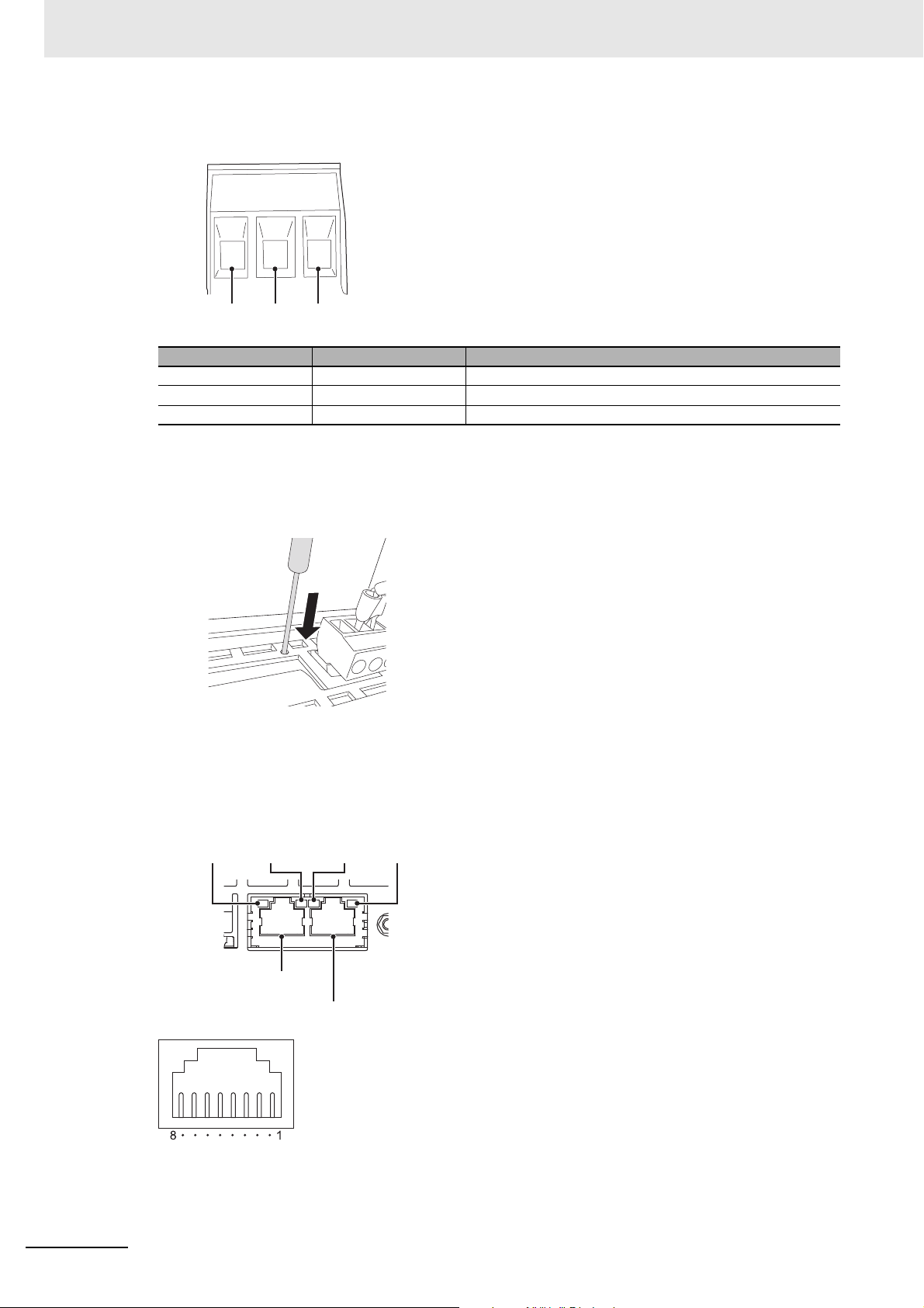
2 Configuration Units
Pin No. 1 2 3
Ethernet port 1
Ethernet port 2
Ethernet Port 1
Indicators
Ethernet Port 2
Indicators
ACT
indicator
LINK
indicator
ACT
indicator
LINK
indicator
Power Supply Connector Pin Arrangement
Pin No. Signal name
1 +24 V +24-V input
20 V 0 V
3 FG Functional ground
Name
Reset Switch
Use a precision screwdriver or similar device with a diameter of less than 2.4 mm. The reset switch
performs the same function as cycling the power supply.
Ethernet Ports
• Port Pin Arrangement and Indicator Locations
2 - 6
NA-series Programmable Terminal Hardware User’s Manual (V117)
Page 51

2 Configuration Units
15 mm min.
• Connecting Devices That Support IEEE 802.3i (10BASE-T) or IEEE 802.3u (100BASE-TX)
Pin No. Signal name Name
1 TD+ Twisted-pair output (differential output)
2 TD- Twisted-pair output (differential output)
3 RD+ Twisted-pair input (differential input)
4 BI D+ Protection circuit
5 BI D- Protection circuit
6 RD- Twisted-pair input (differential input)
7 BI D+ Protection circuit
8 BI D- Protection circuit
2-1 NA Units
• Connecting Devices That Support IEEE 802.3ab (1000Base-T)
Pin No. Signal name Name
1 TRD0+ Send/receive data 0+
2 TRD0- Send/receive data 03 TRD1+ Send/receive data 1+
4 TRD2+ Send/receive data 2+
5 TRD2- Send/receive data 26 TRD1- Send/receive data 17 TRD3+ Send/receive data 3+
8 TRD3- Send/receive data 3-
If you use a cable with a hood or boot, make sure that the mating length is at least 15 mm, as shown
in the following figure.
• Ethernet Port Indicators
Indicator Color Status Description
LINK --- Not lit. A link was not established.
• The cable is not connected.
• The power supply is OFF or the NA Unit was reset.
Green Lit. The link was established.
ACT --- Not lit. The link is on standby.
Orange Flashing. Data is being sent or received.
2
2-1-1 Components and Functions
NA-series Programmable Terminal Hardware User’s Manual (V117)
2 - 7
Page 52

2 Configuration Units
(c)
(d)
(a)
(b)
ID Information Label
You can check the ID information of the NA Unit with the ID information label on the back of the NA
Unit.
An example is shown below. The label varies with the model and applicable standards.
No. Name Description
(a) Model Gives the model of the NA Unit.
(b) Standards Gives the standards for which the NA Unit is certified.
(c) MAC addresses Give the MAC addresses of the Ethernet ports.
(d) Lot number Gives the lot number of the NA Unit.
DDMYY: Lot number, : For use by OMRON
M is 1 to 9 for January to September, X for October, Y for November, and
Z for December.
2 - 8
NA-series Programmable Terminal Hardware User’s Manual (V117)
Page 53

2-2 SD Memory Cards
Additional Information
This section describes how to use an SD Memory Card to transfer the project or save log data.
2-2-1 Models and Specifications
SD and SDHC memory cards are supported, but use the OMRON-specified SD Memory Cards. (Refer
to 1-3-3 Other Optional Products on page 1-6.) OMRON is not responsible for the operation, performance, or write life of any other memory card.
Write Protection Key
You will not be able to write to the SD Memory Card if the key is set to the LOCK position. (Use
this setting to prevent overwriting.)
2 Configuration Units
2-2 SD Memory Cards
2
2-2-1 Models and Specifications
2-2-2 Applications
You can use the SD Memory Card for the following applications.
• Automatically transferring the project data (which includes the screen data) created on the Sysmac
Studio to an HMI
• Updating the HMI system program
• Recording log data (data log and user alarms)
2-2-3 Installing and Removing
This section describes the methods to install and remove an SD Memory Card.
Refer to the NA-series Programmable Terminal Software User’s Manual (Cat. No. V118) for information
on executing actions and information on system-defined variables.
Before Using an SD Memory Card
Observe the following precautions while an SD Memory Card is inserted.
• Before you remove the SD Memory Card, execute the EjectSDMemory action and check the
_HMI_CanEjectSDCard system-defined variable to make sure that the power supply to the SD Memory Card is stopped.
• Before you turn OFF the HMI power supply, execute the EjectSDMemory action and check the
_HMI_CanEjectSDCard system-defined variable to make sure that the power supply to the SD Memory Card is stopped.
NA-series Programmable Terminal Hardware User’s Manual (V117)
2 - 9
Page 54

2 Configuration Units
• Never insert the SD Memory Card facing the wrong way.
If the SD Memory Card is inserted forcibly, it may become unusable.
• To format the SD Memory Card (e.g., to delete all of the data), use the SD Formatter for
SD/SDHC/SDXC provided by the SD Association.
SD Association: https://www.sdcard.org/
• The SD Memory Card uses flash memory, and so its service life is limited. When the end of the SD
Memory Card’s service life approaches, the ability to write data is lost, and data is sometimes not
retained after writing. The service life depends on the size of the data that is written and on the ambient temperature. For the unlikely event that data is lost, it is recommended to periodically back up
data.
Installing the SD Memory Card
1 Insert the SD Memory Card into the slot on the back of the NA Unit with the label facing upward
when viewed from the back of the NA Unit.
2 Push the SD Memory Card securely into the compartment.
Removing the SD Memory Card
1 Execute the EjectSDMemory action.
2 Use the _HMI_CanEjectSDCard system-defined variable to confirm that the power supply to the
SD Memory Card is stopped, and then remove the SD Memory Card.
2 - 10
The SD Memory Card will be ejected from the compartment.
3 Pull out the SD Memory Card.
NA-series Programmable Terminal Hardware User’s Manual (V117)
Page 55

2-3 USB Memory Devices
Precautions for Correct Use
This section describes how to use a USB Memory Device to transfer the project or save log data.
2-3-1 Models and Specifications
USB Memory Devices that comply with the USB 2.0 standard are supported, but use one of the USB
Memory Devices specified by OMRON. (Refer to 1-3-3 Other Optional Products on page 1-6.) OMRON
is not responsible for the operation, performance, or write life of any other USB Memory Device.
2 Configuration Units
2-3 USB Memory Devices
2
2-3-2 Applications
You can use the USB Memory Device for the following applications.
• Automatically transferring the project data (which includes the screen data) created on the Sysmac
Studio to the HMI
• Updating the HMI system program
• Recording log data (data log and user alarms)
2-3-3 Installing and Removing
This section describes methods to install and remove an USB Memory.
Refer to the NA-series Programmable Terminal Software User’s Manual (Cat. No. V118) for information
on subroutines.
You can connect only one USB memory device at the same time.
Before Using a USB Memory Device
2-3-1 Models and Specifications
Observe the following precautions while the USB Memory Device is being accessed.
• Before you remove the USB Memory Device, execute EjectUSBDevice in a subroutine.
• Before you turn OFF the power supply to the HMI, execute EjectUSBDevice in a subroutine.
• Never insert the USB Memory Device facing the wrong way.
If the USB Memory Device is inserted forcibly, it may become unusable.
• To format a USB Memory Device (e.g., to delete all of the data), use a Windows formatting utility and
format to FAT32.
• The USB Memory Devices use flash memory, and so their service life is limited. When the end of the
USB Memory Device’s service life approaches, the ability to write data is lost, and data is sometimes
not retained after writing. The service life depends on the size of the data that is written and on the
ambient temperature. For the unlikely event that data is lost, it is recommended to periodically back
up data.
NA-series Programmable Terminal Hardware User’s Manual (V117)
2 - 11
Page 56

2 Configuration Units
Installing the USB Memory Device
1 Insert the USB Memory Devices into the USB host port on the back of the NA Unit.
2 Push the USB Memory Device all of the way in.
Removing the USB Memory Device
1 Execute EjectUSBDevice in a subroutine and then remove the USB Memory Device.
2 - 12
NA-series Programmable Terminal Hardware User’s Manual (V117)
Page 57

2-4 Support Software
Back Panel of
NA Unit
Sysmac Studio
Commercially available
USB cable
USB slave port
Bottom Panel of
NA Unit
This Sysmac Studio is used to create, debug, and maintain applications for NA-series Programmable
Te rm i na l s.
2-4-1 Connection Methods
With an NA-series Programmable Terminal, you can connect the Sysmac Studio online in the following
ways.
2 Configuration Units
2-4 Support Software
2
Connecting with USB
Use a commercially available USB cable for a USB connection.
You do not need to specify the connected device on the Sysmac Studio.
2-4-1 Connection Methods
NA-series Programmable Terminal Hardware User’s Manual (V117)
2 - 13
Page 58

2 Configuration Units
Connecting with Ethernet
You can use a direct connection or connect through an Ethernet switch by connecting to Ethernet port 2
on the NA Unit.
Sysmac Studio
Ethernet cable (direct
connection or connection
through an Ethernet switch)
Connect to Ethernet port 2 (on the right).
Ethernet port 1
Back Panel of
NA Unit
Ethernet port 2
Back Panel of
NA Unit
• Connect the Sysmac Studio to Ethernet port 2.
• The IP address and connection device do not need to be specified at the Sysmac Studio. Select the
Direct Connection with Sysmac Studio Check Box under HMI Settings − TCP/IP Settings and then
connect to Ethernet port 2.
• You can make the connection either with or without a switching hub.
• The Ethernet port on the NA Unit supports Auto-MDI, so you can use either a cross cable or a
straight cable if you connect directly to the computer.
Refer to the NA-series Programmable Terminal Device Connection User's Manual (Cat. No. V119) for
information on recommended Ethernet switches and connection details.
2 - 14
NA-series Programmable Terminal Hardware User’s Manual (V117)
Page 59

Installation and Wiring
This section describes how to install and wire an NA Unit.
3-1 Processing at Power ON and Power OFF . . . . . . . . . . . . . . . . . . . . . . . . . . 3-2
3-1-1 Power ON Operation . . . . . . . . . . . . . . . . . . . . . . . . . . . . . . . . . . . . . . . . . . . . 3-2
3-1-2 Power OFF Operation . . . . . . . . . . . . . . . . . . . . . . . . . . . . . . . . . . . . . . . . . . . . 3-2
3-2 Fail-safe Measures . . . . . . . . . . . . . . . . . . . . . . . . . . . . . . . . . . . . . . . . . . . . . 3-3
3-2-1 Power ON Sequence . . . . . . . . . . . . . . . . . . . . . . . . . . . . . . . . . . . . . . . . . . . . 3-3
3-3 Installing NA Units . . . . . . . . . . . . . . . . . . . . . . . . . . . . . . . . . . . . . . . . . . . . . 3-4
3-3-1 Installation in a Control Panel . . . . . . . . . . . . . . . . . . . . . . . . . . . . . . . . . . . . . . 3-4
3-4 Wiring Methods . . . . . . . . . . . . . . . . . . . . . . . . . . . . . . . . . . . . . . . . . . . . . . . 3-9
3-4-1 Power Supply Wiring . . . . . . . . . . . . . . . . . . . . . . . . . . . . . . . . . . . . . . . . . . . . 3-9
3-4-2 Wiring the Ethernet Port . . . . . . . . . . . . . . . . . . . . . . . . . . . . . . . . . . . . . . . . . 3-13
3-4-3 Wiring the Serial Port . . . . . . . . . . . . . . . . . . . . . . . . . . . . . . . . . . . . . . . . . . . 3-13
3-5 Control Panel Installation . . . . . . . . . . . . . . . . . . . . . . . . . . . . . . . . . . . . . . 3-14
3-5-1 Temperature . . . . . . . . . . . . . . . . . . . . . . . . . . . . . . . . . . . . . . . . . . . . . . . . . . 3-14
3-5-2 Humidity . . . . . . . . . . . . . . . . . . . . . . . . . . . . . . . . . . . . . . . . . . . . . . . . . . . . . 3-15
3-5-3 Vibration and Shock . . . . . . . . . . . . . . . . . . . . . . . . . . . . . . . . . . . . . . . . . . . . 3-16
3-5-4 Atmosphere . . . . . . . . . . . . . . . . . . . . . . . . . . . . . . . . . . . . . . . . . . . . . . . . . . 3-16
3-5-5 Electrical Environment . . . . . . . . . . . . . . . . . . . . . . . . . . . . . . . . . . . . . . . . . . 3-17
3-5-6 Grounding . . . . . . . . . . . . . . . . . . . . . . . . . . . . . . . . . . . . . . . . . . . . . . . . . . . . 3-19
3
NA-series Programmable Terminal Hardware User’s Manual (V117)
3 - 1
Page 60

3 Installation and Wiring
Precautions for Safe Use
WARNING
WARNING
3-1 Processing at Power ON and Power
OFF
Do not attempt to disassemble, repair, or modify the NA Unit. It may cause NA Unit to lose its
safety function.
Do not attempt to take the NA Unit apart and do not touch the product inside while the power
is being supplied. Otherwise it may result in electric shock.
3-1-1 Power ON Operation
Confirm the safety of the system before turning ON or OFF the power supply, or pressing the
reset switch.
Operation until Operation Ready Status
The NA Unit will enter operation-ready status after the following time elapses once power supply starts.
NA Unit Startup Time at Power ON
It takes approximately 30 seconds for the NA Unit to start up. The startup time is affected by the contents of the project and the presence or absence of an SD Memory Card.
3-1-2 Power OFF Operation
NA Unit operation may not be dependable for momentary power interruptions.
Implement countermeasures for momentary power interruptions at the power supply.
Precautions for Power Interruptions
Observe the following precautions when power is interrupted.
SD Memory Card access in progress
Transferring the project or other
data in process
3 - 2
Item Description
Any write data may be lost.
The operation is interrupted. As a result, an error will occur the next time that
the power is turned ON. Transfer the data again.
NA-series Programmable Terminal Hardware User’s Manual (V117)
Page 61

3-2 Fail-safe Measures
Precautions for Safe Use
3 Installation and Wiring
Provide safety measures in external circuits to ensure safety in the system if an abnormality
occurs due to malfunction of the NA Unit or due to other external factors affecting operation.
Not doing so may result in serious accidents due to incorrect operation.
The circuits associated with safety measures, such as emergency stop circuits, interlock circuits, and limit circuits, must be provided in external control circuits.
External safety measures must be provided to ensure the safe operation of the system from
when the power supply is turned ON until execution of the project starts.
Unintended operation may occur when an error occurs in memory or other data. As a countermeasure for such problems, external safety measures must be provided to ensure safe operation of the system.
Provide measures in the communications system and in the user program to ensure safety in
the overall system even if errors or malfunctions occur.
You must implement fail-safe measures to provide sufficient protection in the event that abnormal signals or problems occur as the result of broken signal lines or momentary power interruptions. Not doing so may result in serious accidents due to incorrect operation.
3-2-1 Power ON Sequence
We recommend the following sequence for turning ON the power supplies.
(1) Ethernet switches and other network devices
(2) Connected devices
(3) NA Unit
WARNING
3-2 Fail-safe Measures
3
3-2-1 Power ON Sequence
If you turn ON the power supply to the connected device after you turn ON the power supply to the NA
Unit, an error may occur depending on system settings.
It takes up to approximately 30 seconds for execution of the HMI project to start after the power
is turned ON. External communications are also not performed during this period. Implement
fail-safe measures so that connected devices do not operate incorrectly, including measures to
check the execution of the HMI project.
NA-series Programmable Terminal Hardware User’s Manual (V117)
3 - 3
Page 62

3 Installation and Wiring
Precautions for Correct Use
3-3 Installing NA Units
This section describes how to install an NA Unit.
• Follow the instructions in this manual to correctly perform installation.
• Do not install or store the NA Unit in any of the following locations:
• Locations subject to severe changes in temperature
• Locations subject to temperatures or humidity outside the range specified in the specifications
• Locations subject to condensation as the result of high humidity
• Locations subject to corrosive or flammable gases
• Locations subject to strong shock or vibration
• Locations outdoors subject to direct wind and rain
• Locations subject to strong ultraviolet light
• Locations subject to dust
• Locations subject to direct sunlight
• Locations subject to splashing oil or chemicals
• Take appropriate and sufficient countermeasures when installing systems in the following
locations:
• Locations subject to static electricity or other forms of noise
• Locations subject to strong electric field or magnetic field
• Locations close to power supply lines
• Locations subject to possible exposure to radioactivity
• Mounting Panel
• To conform to UL Type 1 standards, the mounting panel thickness must be 1.6 to 6.0 mm.
• To conform to UL Type 4X standards, the thickness must be 1.6 to 4.5 mm.
To conform to UL Type 4X standards, always use the NA5-W with a High-pressure Waterproof Attachment (PWA). If you do not use a PWA, there is a risk of water entry,
which may cause severe equipment damage.
Do not use the NA Unit outdoors.
• Tighten the Mounting Brackets evenly to a torque of between 0.5 and 0.6 N·m to maintain
water and dust resistance. If the tightening torque exceeds the specified range or the tightening is not even, deformation of the front panel may occur. Make sure the panel is not
dirty or warped, that the front surface is smooth, and that the panel is strong enough to
hold the NA Unit.
3-3-1 Installation in a Control Panel
Installation in a Control Panel
The NA Unit is installed by embedding it in a control panel. Panel Mounting Brackets and a Phillips
screwdriver are required to mount the NA Unit. The required number of Panel Mounting Brackets are
included with the NA Unit.
To conform to UL Type 4X standards, the thickness must be 1.6 to 4.5 mm. To conform to UL Type 4X
standards, always use the NA5-W with a High-pressure Waterproof Attachment (PWA). If
you do not use a PWA, there is a risk of water entry, which may cause severe equipment damage.
3 - 4
NA-series Programmable Terminal Hardware User’s Manual (V117)
Page 63

3 Installation and Wiring
Panel Mounting Bracket Phillips screwdriver
High-pressure Waterproof Attachment (PWA)
Use the following installation procedure.
3-3 Installing NA Units
1 Open a hole in which to embed the NA Unit with the following dimensions and insert the NA Unit
from the front side of the panel.
Vertical
Horizontal
Recommended panel thickness: 1.6 to 6.0 mm
Model Dimensions
NA5-15W
NA5-12W
NA5-9W
NA5-7W
392
310
261
197
+1/-0
+1/-0
+1/-0
+ 0.5/-0
× 268
× 221
× 166
× 141
+1/-0
mm (horizontal × vertical)
+1/-0
mm (horizontal × vertical)
+1/-0
mm (horizontal × vertical)
+0.5/-0
mm (horizontal × vertical)
3
3-3-1 Installation in a Control Panel
2 To conform to UL Type 4X standards, the panel thickness must be between 1.6 and 4.5 mm.
Always use the NA5-W with a High-pressure Waterproof Attachment (PWA) in
applications requiring UL Type 4X level protection. This is mandatory because there is a risk of
water entry, which may cause severe equipment damage.
Make sure that the internal dimensions at the back of the PWA allow mounting.
Model Dimensions without PWA Dimensions with PWA
NA5-15W 420 × 291 mm 430 × 306 mm
NA5-12W 340 × 244 mm 348 × 259 mm
NA5-9W 290 × 190 mm 298 × 203 mm
NA5-7W 236 × 165 mm 236 × 178 mm
Model PWA model number
NA5-15W NA-15WATW01
NA5-12W NA-12WATW01
NA5-9W NA-9WATW01
NA5-7W NA-7WATW01
Slide the PWA over the NA Unit from the back until the flat side of the PWA is flat against the inside of
the panel, as shown in the following figure.
NA-series Programmable Terminal Hardware User’s Manual (V117)
3 - 5
Page 64

3 Installation and Wiring
3 Attach the panel mounting brackets from the back of the panel as shown in the following figure.
The number of mounting brackets depends on the size of the NA Unit, as shown in the following
table. Refer to Bracket Mounting Locations for Different Units on page 3-8.
Model Number of Panel Mounting Brackets
NA5-15W 8 locations
NA5-12W 6 locations
NA5-9W 4 locations
NA5-7W 4 locations
Catch the brackets in the mounting holes in the NA Unit, pull forward lightly, and then use a Phillips screwdriver to tighten the screws and secure the NA Unit to the panel, which will be held
between the mounting brackets and the NA Unit.
Locations to Catch the
Mounting Brackets (Side View)
Optional High-pressure
Panel
Waterproof Attachment (PWA)
Mounting bracket
NA Unit
mounting holes
View without PWA
3 - 6
NA-series Programmable Terminal Hardware User’s Manual (V117)
Page 65

3 Installation and Wiring
Precautions for Safe Use
Precautions for Correct Use
Additional Information
• Do not let metal particles enter the NA Unit when preparing the panel.
• To conform to UL Type 4X standards, the thickness must be 1.6 to 4.5 mm.
To conform to UL Type 4X standards, always use the NA5-W with a High-pressure Waterproof Attachment (PWA). If you do not use a PWA, there is a risk of water entry,
which may cause severe equipment damage.
• Tighten the Mounting Brackets evenly to a torque of between 0.5 and 0.6 N·m to maintain
water and dust resistance. If the tightening torque exceeds the specified value, or the tightening is not even, deformation of the front panel may occur. What is more, make sure the panel
is not dirty or warped and that it is strong enough to hold the NA Unit.
• As the rubber packing will deteriorate, shrink, or harden depending on the operating environment, periodical inspection is necessary.
3-3 Installing NA Units
3
• Completely shield the gap at openings in the control panel or operation panel with a gasket.
• Refer to Grounding on page 3-12 and wire the functional ground terminal ( ) of the
NA-series PT as required.
The NA Units comply with shipbuilding standards. Refer to Conformance to Shipbuilding Stan-
dards on page 21 for information on applicable shipbuilding standards.
3-3-1 Installation in a Control Panel
NA-series Programmable Terminal Hardware User’s Manual (V117)
3 - 7
Page 66

3 Installation and Wiring
Additional Information
Bracket Mounting Locations for Different Units
When you mount an NA Unit, secure it with the mounting brackets as shown in the following figures.
• NA5-15W
Secure the NA Unit with mounting brackets in the eight locations shown below.
• NA5-12W
Secure the NA Unit with mounting brackets in the six locations shown below.
•NA5-9W
Secure the NA Unit with mounting brackets in the four locations shown below.
•NA5-7W
3 - 8
Secure the NA Unit with mounting brackets in the four locations shown below.
NA-series Programmable Terminal Hardware User’s Manual (V117)
Page 67

3-4 Wiring Methods
Precautions for Safe Use
Precautions for Correct Use
This section describes how to wire an NA Unit.
3 Installation and Wiring
Make sure that the voltage and current that are input to the NA Unit are within the specified
ranges. Inputting voltages or currents that are outside of the specified ranges may cause accidents or fire.
Be sure that all terminal block screws and cable connector screws are tightened to the torque
specified in the relevant manuals. The loose screws may result in fire or malfunction.
Do not touch any equipment when power is being supplied or immediately after the power
supply is turned OFF. You may be burnt.
3-4-1 Power Supply Wiring
Connect a 24-VDC power supply to the power supply input terminals.
• Use a DC power with a slight voltage fluctuation and that will provide a stable output even if
the input is momentarily interrupted for 10 ms. Also use the one with reinforced insulation or
double insulation.
Rated Power Supply Voltage: 24VDC (Allowable range 19.2 to 28.8VDC)
• Do not perform a dielectric strength test.
WARNING
WARNING
3-4 Wiring Methods
3
3-4-1 Power Supply Wiring
• Do not allow wire clippings, shavings, or other foreign material to enter the NA Unit. Otherwise, burning, failure, or malfunction may occur. Cover the NA Unit or take other suitable
countermeasures, especially during wiring work.
• To use a power supply that does not contain a protection circuit, supply power to the NA Unit
through a fuse or other protective element.
Power Supply Specifications
The specifications of a connectible power supply are given in the following table.
Item Value
Rated supply voltage 24 VDC
Allowable voltage fluctuation range 19.2 to 28.8 VDC (24 VDC ±20%)
Power supply capacity NA5-15W: 47 W min.
NA5-12W: 45 W min.
NA5-9W: 40 W min.
NA5-7W: 35 W min.
NA-series Programmable Terminal Hardware User’s Manual (V117)
3 - 9
Page 68

3 Installation and Wiring
Pin No. 1 2 3
Functional ground
(Refer to Grounding, below.)
Breaker
24-VDC
power supply
Wiring Materials
Use the enclosed power supply connector to connect the power supply to the NA Unit.
• We recommend that you use a power supply cable with the following stranded wires. Wire the power
supply giving sufficient consideration to the voltage drop and heat generation for the cable length in
the installation environment.
Applicable Wires (Stranded Wires)
Size Conductor cross-section
AWG12 to AWG22
Power Supply Connector
0.35 to 3.31 mm
2
Pin No. Signal name Name
1 +24 V +24-V input
20 V0 V
3 FG Functional ground
Wiring
3 - 10
NA-series Programmable Terminal Hardware User’s Manual (V117)
Page 69

Wiring Procedure
0 V
+24 V
Power line
Use the following procedure to connect the power supply.
3 Installation and Wiring
1 Remove the sheath from the power supply wires.
7 mm
2 Remove the power supply connector from the NA Unit and loosen the terminal block screws.
3-4 Wiring Methods
3
3-4-1 Power Supply Wiring
3 Insert the wires all the way to the back of the connector and then turn the screws clockwise to
secure the wires.
Use a small flat-blade screwdriver and tighten the screws to between 0.5 and 0.6 N·m.
NA-series Programmable Terminal Hardware User’s Manual (V117)
4 Attach the power supply connector to the NA Unit.
3 - 11
Page 70

3 Installation and Wiring
Precautions for Correct Use
Precautions for Safe Use
Precautions for Correct Use
Clockwise Counterclockwise
Observe the following precautions to prevent broken wires.
• When you remove the sheath, be careful not to damage the conductor.
• Connect the conductor without twisting the wires.
• Do not weld the conductors. If you do so, vibration may cause the wires to break.
• Do not apply stress to the cable after you have connected the wires.
• Before you insert a wire into a terminal hole, turn the screw that tightens the terminal counterclockwise until the terminal is no longer visible. Then, insert the wire so that it is held on the
terminal and screw side of the case and turn the screw clockwise to tighten the terminal.
• Faulty contact will result if you turn the screw counterclockwise to secure the wire. If necessary, remove the wire, make sure it is inserted in the terminal hole, and then connect it again.
Grounding
The NA Unit has a functional ground terminal ( ). Wire the functional ground terminal according to
the following conditions.
• If there is a difference in electrical potential between the NA Unit and the connected devices, ground
them as shown in the following figure.
Ground to
one point.
To prevent malfunctions caused by noise, ground the NA Unit correctly.
If the connected devices are separated too far from the NA Unit to ground them to the same
point and the NA Unit is installed in the same panel as devices that generate noise (such as
motors and inverters), do not ground the NA Unit.
3 - 12
NA-series Programmable Terminal Hardware User’s Manual (V117)
Page 71

3-4-2 Wiring the Ethernet Port
Refer to the NA-series Programmable Terminal Device Connection Manual (Cat. No. V120) for informa-
tion on wiring the Ethernet ports.
3 Installation and Wiring
3-4-3 Wiring the Serial Port
The serial port is for future expansion. Do not wire this port.
3-4 Wiring Methods
3
3-4-2 Wiring the Ethernet Port
NA-series Programmable Terminal Hardware User’s Manual (V117)
3 - 13
Page 72

3 Installation and Wiring
NA Unit
Air filter
Fan
Forced Ventilation Method
NA Unit
3-5 Control Panel Installation
To ensure system reliability and safety, the system must be designed and configured according to the
installation environment (temperature, humidity, vibration, shock, corrosive gases, overcurrent, noise,
etc.).
3-5-1 Temperature
Panels have been reduced in size due to space-saving and miniaturization in devices and systems, and
the temperature inside the panel may be at least 10 to 15°C higher than outside the panel. Implement
the following measures against overheating at the installation site and in the panel, and allow a sufficient margin for the temperature.
High Temperatures
Use the following cooling methods as required, taking into account the ambient temperature and the
amount of heating inside the panel.
Natural Cooling
Natural cooling relies on natural ventilation through slits in the panel, rather than using cooling
devices such as fans or coolers. When using this method, observe the following points.
• Do not install the NA Unit at the top of the panel, where hot air tends to stagnate.
• To provide ventilation space above and below the NA Unit, leave sufficient distance from other
devices, wiring ducts, etc.
• Do not mount the NA Unit in the wrong direction (e.g., vertically or upside down). Doing so may
cause abnormal heating in the NA Unit.
• Do not install the NA Unit above any heat-generating equipment, such as heaters, transformers,
and devices with high resistance.
• Do not install the NA Unit in a location exposed to direct sunlight.
Forced Ventilation (with Fan at Top of Panel)
3 - 14
NA-series Programmable Terminal Hardware User’s Manual (V117)
Page 73

3 Installation and Wiring
Forced Circulation
NA Unit
Moisture absorber
Control panel
Heater
Examples of Measures against Condensation
NA Unit
Power ON
Forced Air Circulation (with Fan in Closed Panel)
3-5 Control Panel Installation
Room Cooling (Cooling the Entire Room Where the Control Panel Is Located)
Low Temperatures
The NA Unit may not start normally if the temperature is below 0°C when the power is turned ON.
Maintain an air temperature of at least approximately 5°C inside the panel, by implementing measures
such as installing a low-capacity space heater in the panel. Alternatively, leave the NA Unit power ON to
keep the NA Unit warm.
3-5-2 Humidity
Rapid temperature changes can cause condensation to occur, resulting in malfunctioning due to
short-circuiting. When there is a possibility of this occurring, take measures against condensation, such
as leaving the NA Unit power ON at night or installing a heater in the control panel to keep it warmer.
NA Unit
Room Cooling
Cooler
Control panel
3
3-5-2 Humidity
NA-series Programmable Terminal Hardware User’s Manual (V117)
3 - 15
Page 74

3 Installation and Wiring
3-5-3 Vibration and Shock
The NA Unit is tested for conformity with the sine wave vibration test method (IEC 60068-2-6) and the
shock test method (IEC 60068-2-27) of the Environmental Testing for Electrotechnical Products. It is
designed so that malfunctioning will not occur within the specifications for vibration and shock. If, however, the NA Unit is to be used in a location in which it will be directly subjected to regular vibration or
shock, then implement the following countermeasures:
• Separate the control panel from the source of the vibration or shock.
Or, secure the NA Unit and the panel with rubber padding.
• Make the building or the floor vibration resistant.
• To prevent shock when other devices in the panel such as electromagnetic contactors operate,
secure either the source of the shock or the NA Unit with rubber padding.
3-5-4 Atmosphere
Using the NA Unit in any of the following locations can cause defective contact with connectors and corrosion of components. Implement countermeasures such as purging the air as required.
• In locations exposed to dust, dirt, salt, metal powder, soot, or organic solvents, use a panel with an
airtight structure. Be careful of temperature increases inside the panel.
• In locations exposed to corrosive gas, purge the air inside the panel to clear the gas and then pressurize the inside of the panel to prevent gas from entering from outside.
• In locations where flammable gas is present, either use an explosion-protected construction or do not
use the NA Unit.
3 - 16
NA-series Programmable Terminal Hardware User’s Manual (V117)
Page 75

3-5-5 Electrical Environment
When installing or wiring devices, make sure that there will be no danger to people and that noise will
not interfere with electrical signals.
Installation Locations for NA Unit
Install the NA Unit as far away as possible from high-voltage (600 V or higher) and power devices to
ensure safe operation and maintenance.
Example of Recommended Equipment Arrangement
3 Installation and Wiring
3-5 Control Panel Installation
NA Unit
Control panel Control panel High-voltage
power panel
Example of Poor Equipment Arrangement
NA Unit
Control panel Control panel High-voltage
power panel
Examples of Equipment Arrangement in
Panel with High-voltage Devices
External Wiring
Wiring, and noise countermeasures in particular, must be based mostly on experience, and it is necessary to closely manage wiring based on information in the manuals.
3
3-5-5 Electrical Environment
Wiring Routes
Each of the following combinations includes different signal types, properties, or levels. They will
cause the signal-to-noise ratio to drop due to factors such as electrical induction. As a general rule
when wiring, either use separate cables or separate wiring routes for these items. Future maintenance operations and changes to the system will also be made easier by carefully organizing the
wiring from the start.
• Power lines and signal lines
• Input signals and output signals
• Analog signals and digital signals
• High-level signals and low-level signals
• Communications lines and power lines
• DC signals and AC signals
• High-frequency devices (such as Inverters) and signal lines (communications)
NA-series Programmable Terminal Hardware User’s Manual (V117)
3 - 17
Page 76

3 Installation and Wiring
Partitioning Methods for Signal and Power Supply Cables
Signal
cables
(A)
Signal
cables
(C)
Signal
cables
(B)
(a) (b)
(c) (d)
Signal cables
Signal cables
Signal cables
Power supply
cables
Power supply
cables
Power supply
cables
Partition
Wiring Methods
Observe the following points when wiring power supply and signal cables.
• When routing signal cables with different characteristics through the same duct, always keep
them separated.
• As much as possible, avoid routing multiple power supply lines through the same duct. If it cannot
be avoided, then construct a partition between them in the duct and ground the partition.
• To avoid overheating the conduits when using conduits for wiring, do not place wires for a single
circuit in separate conduits.
Power supply
Load
Power supply
Power supply
Incorrect
Load
Correct
Load
Correct
Parallel Wiring (Single Phase)
• Power cables and signal cables adversely affect each other. Do not wire them in parallel.
• Noise induction may occur if the NA Unit is installed in a panel that includes high-voltage devices.
Wire and install them as far apart as possible.
3 - 18
NA-series Programmable Terminal Hardware User’s Manual (V117)
Page 77

3 Installation and Wiring
Example: Separating NA Unit from Power Lines
Metal tubing
200 mm
200 mm
High-voltage power panel
Power lines
Power lines
Ground of
100 Ω or less
NA Unit
NA Unit
• Either install the NA Unit a minimum of 200 mm away from high-voltage lines or power lines, or
place the high-voltage lines or power lines in metal tubing and completely ground the metal tubing
to 100 Ω or less.
3-5 Control Panel Installation
3-5-6 Grounding
Grounding has the following two purposes.
• Protective Grounding
Protective grounding is done to ensure safety. It is intended to prevent electrical shock by holding the
electrical potential at the grounding potential that is generated by factors such as leakage, induction,
or failure.
• Functional Grounding
Functional grounding is done to protect device and system functions, including prevention of noise
from external sources, or prevention of noise from devices or equipment that could have harmful
effects on other devices or equipment.
Grounding requirements sometimes depend on the situation, and they may be found based on experimentation. It is important to sufficiently check the particular circumstances before grounding.
Grounding Methods and Precautions
Principles of One-point Grounding
3
3-5-6 Grounding
NA-series Programmable Terminal Hardware User’s Manual (V117)
For devices to operate properly, the reference potential between the devices must be stabilized. Use
one-point grounding so that noise current does not flow to ground lines between the devices.
• Use one-point grounding as shown in figure (a). Connect to the ground pole of the other devices.
• Never connect to the same ground as a device that draws a large amount of power, such as a
motor or inverter. Ground the devices separately to avoid mutually adverse influences.
• To prevent electrical shock, do not connect to ground poles (or steel frames) to which multiple
devices are connected.
• Use a ground pole as close to the NA Unit as possible and keep the ground line as short as possible.
3 - 19
Page 78

3 Installation and Wiring
Other
device
Other
device
(c) Independent grounds:
Incorrect
(a) One-point grounding:
Acceptable
(b) Common ground:
Incorrect
Other
device
NA UnitNA Unit NA Unit
Ground of
100 Ω or
less
Insulating material
Channel base
The NA Units are designed to be
mounted so that they are isolated
(separated) from the mounting surface
to protect them from the effects of noise
in the installation environment (e.g., the
environment in which the control panel
is mounted).
Precautions when Grounding
• If the same ground is used for both the signal lines and the enclosure, isolate the channel base (a
grounded metal plate inside a control panel) with an insulating material.
• To prevent influence from leakage current from other electrical devices, electrically isolate the panel
• If high-frequency equipment is present, then ground not only the high-frequency equipment but also
NA Unit Functional Ground Terminal
The NA Unit has the following ground terminal.
Functional ground terminal: Connected to a neutral point in the noise filter to provide a ground when
When the functional ground terminal is correctly grounded, it is generally effective in suppressing power
supply common noise. Occasionally, however, grounding this terminal will result in picking up more
noise, so be careful when using it.
Connections When Using an External Noise Filter
3 - 20
in which the NA Unit is housed from other devices.
the panel itself in which the NA Unit is housed.
power supply noise causes malfunctioning.
External power
supply side
NA Unit side
NA-series Programmable Terminal Hardware User’s Manual (V117)
Page 79

System Program
This section describes the system program that is used by NA-series Programmable
Terminals.
4-1 System Program and NA Unit Startup Status . . . . . . . . . . . . . . . . . . . . . . . 4-2
4-2 System Recovery . . . . . . . . . . . . . . . . . . . . . . . . . . . . . . . . . . . . . . . . . . . . . . 4-3
4-3 System Menu Overview . . . . . . . . . . . . . . . . . . . . . . . . . . . . . . . . . . . . . . . . . 4-6
4-3-1 System Menu Configuration . . . . . . . . . . . . . . . . . . . . . . . . . . . . . . . . . . . . . . . 4-6
4-3-2 Using the System Menu . . . . . . . . . . . . . . . . . . . . . . . . . . . . . . . . . . . . . . . . . . 4-9
4-4 System Menu Details . . . . . . . . . . . . . . . . . . . . . . . . . . . . . . . . . . . . . . . . . . 4-11
4-4-1 Display Settings (Project System Menu) . . . . . . . . . . . . . . . . . . . . . . . . . . . . . .4-11
4-4-2 Language Settings (Project System Menu) . . . . . . . . . . . . . . . . . . . . . . . . . . 4-12
4-4-3 External Device Settings (Project System Menu) . . . . . . . . . . . . . . . . . . . . . . 4-12
4-4-4 User Accounts (Project System Menu) . . . . . . . . . . . . . . . . . . . . . . . . . . . . . . 4-13
4-4-5 NJ/NX/NY Troubleshooter (Project System Menu) . . . . . . . . . . . . . . . . . . . . . 4-14
4-4-6 Alarm Viewer (Project System Menu) . . . . . . . . . . . . . . . . . . . . . . . . . . . . . . . 4-26
4-4-7 Project System Menu Settings (Project System Menu) . . . . . . . . . . . . . . . . . 4-28
4-4-8 Print Settings (Project System Menu) . . . . . . . . . . . . . . . . . . . . . . . . . . . . . . . 4-28
4-4-9 Buzzer Settings (Project System Menu) . . . . . . . . . . . . . . . . . . . . . . . . . . . . . 4-29
4-4-10 Date & Time Settings (Device System Menu) . . . . . . . . . . . . . . . . . . . . . . . . . 4-30
4-4-11 Language Settings (Device System Menu) . . . . . . . . . . . . . . . . . . . . . . . . . . 4-30
4-4-12 Interface Settings (Device System Menu) . . . . . . . . . . . . . . . . . . . . . . . . . . . . 4-31
4-4-13 Brightness Settings (Device System Menu) . . . . . . . . . . . . . . . . . . . . . . . . . . 4-36
4-4-14 Transfer Operations (Device System Menu) . . . . . . . . . . . . . . . . . . . . . . . . . . 4-37
4-4-15 Hardware Diagnostics (Device System Menu) . . . . . . . . . . . . . . . . . . . . . . . . 4-42
4-4-16 Production Information (Device System Menu) . . . . . . . . . . . . . . . . . . . . . . . 4-45
4
NA-series Programmable Terminal Hardware User’s Manual (V117)
4 - 1
Page 80

4 System Program
Precautions for Correct Use
4-1 System Program and NA Unit Startup
Status
The system program is required to start the NA Unit and execute the project in the NA Unit.
• The system program automatically starts when you turn ON the power supply to the NA Unit or when
you press the reset switch while power is supplied.
When the system program starts, one of the following states is entered.
a) If there is an executable project in the NA Unit, the project is automatically executed.
Refer to 4-3-2 Using the System Menu on page 4-9 for the procedure to display the System
Menu.
b) If there is not an executable project in the NA Unit, the System Menu is automatically displayed.
• If there is an error in the system program, the NA Unit will not operate normally.
If you think there is a problem with the system program, system recovery may be necessary.
Refer to 5-2-1 Confirming NA Unit Operation on page 5-4 and 4-2 System Recovery on page 4-3 for
the method to see whether there is an error in the system program and the system recovery procedure.
When you perform system recovery or update the system program, the NA Unit will be returned
to the default status and the project will be deleted.
• You may need to update the system program from time to time, e.g., when support for a new connected device is added to the NA Units. In this case, the system program is automatically downloaded from the Sysmac Studio.
4 - 2
NA-series Programmable Terminal Hardware User’s Manual (V117)
Page 81

4-2 System Recovery
You can implement system recovery if the NA Unit will not start normally or if you want to initialize the
contents of the NA Unit to the default state.
When you implement system recovery, all of the user data is deleted from the NA Unit and the system
program is overwritten with the newest version.
4 System Program
System Recovery Procedure
Use the following procedure for system recovery.
1 Prepare a formatted SD Memory Card or USB Memory Device.
2 Execute the following file in the Sysmac Studio installation media.
Sysmac_Studio_installation_media\Utility\NA_RecoverUpdate\NA_RecoverUpdate___.exe
3 Specify the root folder on the media you prepared in step 1 as the extraction location.
4 Turn OFF the power supply to the NA Unit.
5 Open the battery cover on the back of the NA Unit and set the DIP switch to the settings shown
below. When you finish setting the DIP switch, close the battery cover.
4-2 System Recovery
4
6 Insert the media that you prepared in step 2 into the NA Unit and turn ON the power supply to
the NA Unit.
7 Select the model of NA Unit to use.
NA-series Programmable Terminal Hardware User’s Manual (V117)
4 - 3
Page 82

4 System Program
8 Tap the language to use for system recovery.
9 Select the package that you want to install, and then tap the Install Button.
10 Ta p th e Yes Button.
4 - 4
NA-series Programmable Terminal Hardware User’s Manual (V117)
Page 83

4 System Program
11 When the following message is displayed, remove the media from the NA Unit and turn OFF the
power supply to the NA Unit.
12 Open the battery cover on the back of the NA Unit and set the DIP switch to the settings shown
below. When you finish setting the DIP switch, close the battery cover.
4-2 System Recovery
4
This concludes system recovery.
NA-series Programmable Terminal Hardware User’s Manual (V117)
4 - 5
Page 84

4 System Program
4-3 System Menu Overview
You can use the System Menu to perform operations according to on-screen displays to perform various settings for the NA Unit.
Refer to 4-3-1 System Menu Configuration on page 4-6 for the configuration of the System Menu.
Refer to 4-3-2 Using the System Menu on page 4-9 for the procedures to use the System Menu.
4-3-1 System Menu Configuration
The initial display for the System Menu depends on whether there is a project in the NA Unit.
If there is a project, the Project System Menu is displayed initially. If there is no project, the Device System Menu is displayed initially and you cannot access the Project System Menu.
The following items and functions are displayed on the System Menu.
• Project System Menu (1/2)
4 - 6
Item Description Reference
Display Settings Sets the screen saver and display brightness. P. 4-11
Language Settings Sets the user language and the system language.P. 4-12
External Device Settings Sets the communications settings for connected devices. P. 4-12
User Accounts Sets the user account settings. P. 4-13
NJ/NX/NY Troubleshooter Displays the NJ/NX/NY Troubleshooter. P. 4-14
Alarm Viewer Displays user alarms. P. 4-26
Project System Menu Set-
tings
Device System Menu Calibrates the touch panel. P. 4-42
Sets the starting method for the System Menu. P. 4-28
NA-series Programmable Terminal Hardware User’s Manual (V117)
Page 85

• Project System Menu (2/2)
4 System Program
4-3 System Menu Overview
Item Description Reference
Print Settings Sets up printing/capturing of the NA screens. P. 4-28
Buzzer Settings Sets buzzer sounds. P. 4-29
4
4-3-1 System Menu Configuration
NA-series Programmable Terminal Hardware User’s Manual (V117)
4 - 7
Page 86

4 System Program
• Device System Menu
Item Description Reference
Date & Time Settings Sets the date and time, as well as settings for synchronization
with the time server.
Language Settings Makes settings for the system language. P. 4-30
Interface Settings Makes settings for the NA Unit interface. P. 4-31
Brightness Settings Sets the screen brightness. P. 4-36
Transfer Operations Transfers the project and data. P. 4-37
Hardware Diagnostics Calibrates the touch panel. P. 4-42
Production Information Gives the lot number of the NA Unit and other information. P. 4-45
P. 4- 3 0
4 - 8
NA-series Programmable Terminal Hardware User’s Manual (V117)
Page 87

Additional Information
4-3-2 Using the System Menu
Double-tap.
This section describes how to use the System Menu, including the display methods and how to select
menu items.
The system settings that are made in the Sysmac Studio project data take priority over the settings that are made from the System Menu.
System Menu Display Methods
You can display the System Menu with any of the following methods. Refer to the NA-series Programmable Terminal Software User’s Manual (Cat. No. V118) for information on actions and subroutines.
• Double-tapping one of the four corners of the touch panel
• Executing the ShowSystemMenu action
• Executing the ShowSystemMenu function in a subroutine
4 System Program
4-3 System Menu Overview
4
4-3-2 Using the System Menu
Double-tapping one of the four corners of the touch panel
Double-tapping one of the four corners of the touch panel on the NA Unit.
When you tap one of the four corners of the touch panel, tap one where no object is displayed. If you
tap a corner where an object is displayed, the function of the object is executed. You can also
choose the active locations from the four corners.
Executing the ShowSystemMenu Action
When you create the application, you can create a button on a page and assign the ShowSystemMenu action to that button. Then when you tap the button, the System Menu is displayed.
Executing the ShowSystemMenu Function in a Subroutine
When you create the application, you can create a button on a page and assign that button to a subroutine that executes the ShowSystemMenu function. Then when you tap the button, the System
Menu is displayed.
NA-series Programmable Terminal Hardware User’s Manual (V117)
4 - 9
Page 88

4 System Program
Selecting Menu Items
Tap a menu item or icon on the System Menu to display the corresponding functionality.
Example: Tap the Hardware Diagnostics Icon on the Device System Menu to display the Hardware
Diagnostics Screen.
Leaving the System Menu to Enter Operating Status
Tap the
when you return to Run Status. To enable some settings, you may have to reset the NA Unit.
Exit
Button on the Project System Menu to return to Run Status. Any changes to settings are applied
Common System Menu Operations
This section describes the functions that are common to the entire System Menu.
This button exits the System Menu and places the NA Unit in Run Status or displays the Project System Menu.
This button changes to a page at the next higher level.
This button applies local changes to settings.
4 - 10
NA-series Programmable Terminal Hardware User’s Manual (V117)
Page 89

4-4 System Menu Details
(a)
(b)
(c)
(d)
This section describes the functions that are provided by the System Menu.
4-4-1 Display Settings (Project System Menu)
4 System Program
You can use the display settings to set the following items.
No. Item Description
(a) Screen Saver Enabled Select this check box to use the screen saver.
(b) Type Sets the type of screen saver.
(c) Timeout Sets the time until the screen saver is started in minutes.
(d) Brightness Sets the screen brightness.
4-4 System Menu Details
4
4-4-1 Display Settings (Project System Menu)
NA-series Programmable Terminal Hardware User’s Manual (V117)
4 - 11
Page 90

4 System Program
(a)
(b)
(c)
(d)
(a) (b)
4-4-2 Language Settings (Project System Menu)
You can use the language settings to set the following items.
No. Item Description
(a) User Language Sets the user language.
(b) System Language Displays the system language that is associated with the user lan-
guage.
(c) Keep this setting on as a startup
language
(d) USB Keyboard Layout Sets the layout of a USB keyboard.
If you select this check box, the language that is set as the system
language is used as the startup language.
4-4-3 External Device Settings (Project System Menu)
You can use the external device settings to set the following items.
4 - 12
No. Item Description
(a) Connected Device List Displays a list of the connected devices that are registered in the
project.
(b) Connected Device Communica-
tions Settings
Displays the communications settings of the connected device that
is selected in the list. Refer to the NA-series Programmable Termi-
nal Device Connection User’s Manual (Cat. No. V119) for details.
NA-series Programmable Terminal Hardware User’s Manual (V117)
Page 91

Precautions for Safe Use
Additional Information
4-4-4 User Accounts (Project System Menu)
(j)
(c)
(a)
(b)
(d)
(e)
(f)(g)(h)(i)
You can use the user account settings to set the following items.
• When you change a password, do not reset the NA Unit or turn OFF the power supply before
writing the new password is completed. A failure to store the password may cause the project
to fail to function.
• If you forget a password, there is no way to check for the password on the NA Unit. Use the
Sysmac Studio to check.
4 System Program
4-4 System Menu Details
No. Item Description
(a) Name Sets the name.
(b) Role Sets the rights.
(c) Password Sets the password.
(d) Comment Sets a comment.
(e) Save Saves any changes.
(f) Cancel Discards any changes.
(g) Edits the selected user account.
4
4-4-4 User Accounts (Project System Menu)
(h) Deletes the selected user account.
(i) Adds a user account.
NA-series Programmable Terminal Hardware User’s Manual (V117)
(j) User account table A list of the user accounts that are currently registered is displayed.
4 - 13
Page 92

4 System Program
4-4-5 NJ/NX/NY Troubleshooter (Project System Menu)
The NJ/NX/NY Troubleshooter can be used to access descriptions and countermeasures for errors and
events that occur in the Controller and built-in devices. These functions can be used only when you are
connected to an NJ/NX/NY-series Controller.
Errors and Events That Can Be Monitored
User-defined Errors and User-defined Events
Errors and events can be defined by the user with the Sysmac Studio. Detailed information on troubleshooting also can be set. Refer to Section 1 Overview in the NJ/NX-series Troubleshooting Manual
(Cat. No. W503) and Section 1 Overview of Errors in the NY-series Troubleshooting Manual (Cat. No.
W564-E1) for details.
Controller Errors and Controller Events
These errors and events are generated by an NJ/NX/NY-series Controller. These errors and events
cannot be edited by the user. Refer to Section 1 Overview in the NJ/NX-series Troubleshooting Manual
(Cat. No. W503) and Section 1 Overview of Errors in the NY-series Troubleshooting Manual (Cat. No.
W564-E1) for details.
When Connected to an NX-series CPU Unit
Troubleshooter functions
System configuration element
CPU Unit Applicable
NX Units
EtherCAT Slaves (Sysmac devices)
EtherCAT Slave Terminals
*1. Supported in runtime version 1.07 or higher.
*2. Supported in runtime version 1.03 or higher.
*3. Event logs for individual units cannot be cleared.
*4. Events are not displayed for some NX Units. If an error occurs in an NX Unit that does not display events, an
*5. Errors that occur on a specific NX Unit cannot be cleared separately.
*6. It might be necessary to reset errors in Safety Control Units with a safety program. Refer to the NX-series Safe-
*1
EtherCAT Coupler Units
NX Units Partially appli-
NX Unit Minor Fault event will occur in the EtherCAT Coupler Unit and the unit number of the NX Unit in which
the error occurred will be given in the attached information.
ty Control Unit User’s Manual (Cat. No. Z930) for details on resetting errors in Safety Control Units.
Displaying
errors
Partially appli-
cable
cable
*4
Applicable
Applicable
*4
Clearing
errors
Applicable
Applicable
*5*6
*5 *6
Displaying
error logs
Applicable Applicable
Applicable
Applicable
Applicable
Clearing error
*2
Applicable
*2
Applicable
*2
Applicable
logs
*2 *3
*2 *3
*2 *3
*3
4 - 14
When Connected to an NJ-series CPU Unit
Troubleshooter functions
System configuration element
CPU Rack CPU Unit Applicable
CJ-series Units
Displaying
errors
Applicable
NA-series Programmable Terminal Hardware User’s Manual (V117)
Clearing
errors
Displaying
error logs
Partially applicable
Clearing error
logs
*1
Page 93

4 System Program
Troubleshooter functions
System configuration element
EtherCAT Slaves (Sysmac devices)
EtherCAT Slave Terminals
EtherCAT Coupler Units
NX Units Partially appli-
*1. You cannot display or delete events in the error history (upper four digits of event code are 0000 hex) in a
CJ-series Special Unit mounted on an NJ-series CPU Unit.
*2. Supported in runtime version 1.03 or higher.
*3. Event logs for individual units cannot be cleared.
*4. Events are not displayed for some NX Units. If an error occurs in an NX Unit that does not display events, an
NX Unit Minor Fault event will occur in the EtherCAT Coupler Unit and the unit number of the NX Unit in which
the error occurred will be given in the attached information.
*5. Errors that occur on a specific NX Unit cannot be cleared separately.
*6. It might be necessary to reset errors in Safety Control Units with a safety program. Refer to the NX-series Safe-
ty Control Unit User’s Manual (Cat. No. Z930) for details on resetting errors in Safety Control Units.
Displaying
errors
Applicable
Applicable
*4
cable
Clearing
errors
Applicable*5
*6
Displaying
error logs
Applicable
Applicable
Applicable
Clearing error
*2
Applicable
*2
Applicable
*2
Applicable
logs
*2 *3
*2 *3
*2 *3
4-4 System Menu Details
When Connected to an NY-series CPU Unit
Troubleshooter functions
System configuration element
CPU Unit Applicable
EtherCAT Slaves (Sysmac devices)
EtherCAT Slave Terminals
EtherCAT Coupler Units
NX Units Partially appli-
*1. Supported in runtime version 1.06 or higher.
*2. Event logs for individual units cannot be cleared.
*3. Events are not displayed for some NX Units. If an error occurs in an NX Unit that does not display events, an
NX Unit Minor Fault event will occur in the EtherCAT Coupler Unit and the unit number of the NX Unit in which
the error occurred will be given in the attached information.
*4. Errors that occur on a specific NX Unit cannot be cleared separately.
*5. It might be necessary to reset errors in Safety Control Units with a safety program. Refer to the NX-series Safe-
ty Control Unit User’s Manual (Cat. No. Z930) for details on resetting errors in Safety Control Units.
Displaying
errors
Applicable
Applicable
*3
cable
Clearing
errors
Applicable
*4 *5
Displaying
error logs
Applicable
Applicable
Applicable
Clearing error
*1
Applicable
*1
Applicable
*1
Applicable
logs
*1 *2
*1 *2
*1 *2
4
4-4-5 NJ/NX/NY Troubleshooter (Project System Menu)
Starting and Quitting the NJ/NX/NY Troubleshooter
There are four ways to start the NJ/NX/NY Troubleshooter.
•Select NJ/NX/NY Troubleshooter from the System Menu.
• Execute the ShowTroubleshooter action.
• Execute the ShowTroubleshooter function.
• Set the Troubleshooter operation settings to specify monitoring user-defined or Controller errors.
(The NJ/NX/NY Troubleshooter will be displayed automatically when a user-defined error or Controller error occurs.)
NA-series Programmable Terminal Hardware User’s Manual (V117)
4 - 15
Page 94

4 System Program
Starting from the System Menu
1 Display the System Menu and select NJ/NX/NY Troubleshooter.
2 The NJ/NX/NY Troubleshooter will be started.
Starting from a User Screen
The required settings must be made from the Sysmac Studio.
The following example shows how to execute the Troubleshooter by using an object event.
In this example, settings are performed to execute the Troubleshooter when a Button object is
clicked.
4 - 16
1 Place a Button object on the screen and display Events and Actions.
NA-series Programmable Terminal Hardware User’s Manual (V117)
Page 95

2 Select Click as the event.
Additional Information
3 Select ShowTroubleshooter as the action.
4 System Program
4-4 System Menu Details
4 Specify the name of the Controller to be connected in ControllerName.
5 Specify the name of the page to be displayed while the Troubleshooter is running in StartPage.
If you use runtime version 1.02 or if you do not specify a name for ControllerName, a Controller
status list is displayed on the screen when the Troubleshooter is activated.
4
4-4-5 NJ/NX/NY Troubleshooter (Project System Menu)
NA-series Programmable Terminal Hardware User’s Manual (V117)
4 - 17
Page 96

4 System Program
Starting the Troubleshooter for User-defined Errors or Controller Errors
The required settings are made from the Sysmac Studio.
1 Double-click Troubleshooter under Configurations and Setup in the Multiview Explorer. The
Troubleshooter Settings Tab Page will be displayed in the Edit Pane.
2 Select the Launch on System Event or Launch on User Event Check Box.
3 Generate the type of error that was set in step 2 in the Controller.
4 The NJ/NX/NY Troubleshooter will be started.
Quitting the NJ/NX/NY Troubleshooter
1 Click the Exit Button on the screen that was displayed when the NJ/NX/NY Troubleshooter
started.
2 The display will return to the user screen that was displayed before the NJ/NX/NY Trouble-
shooter started.
4 - 18
NA-series Programmable Terminal Hardware User’s Manual (V117)
Page 97

NJ/NX/NY-series Controller Status Screen
1
7
65
2
4
3
The status of the host to which the NA is currently connected is displayed.
4 System Program
4-4 System Menu Details
No. Item Description
1 Exit Button Quits the Troubleshooter.
2 Title Bar Displays the current date of the NA.
3 Tabs Switch between displaying active events and the event log.
4 Status List Displays the status of the currently connected host.
5 Status Bar Displays information on the Controller that is currently selected.
6 Show Controller Events Displays the Controller Event List Screen of the selected host.
7 Show User Events Displays the User-defined Event Lists Screen.
4
4-4-5 NJ/NX/NY Troubleshooter (Project System Menu)
NA-series Programmable Terminal Hardware User’s Manual (V117)
4 - 19
Page 98
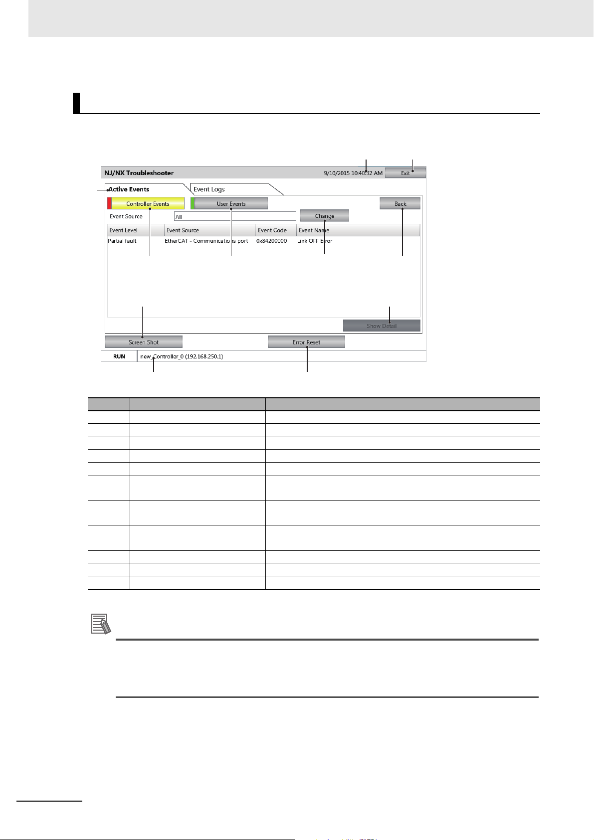
4 System Program
Additional Information
1
10
4 5 7
6
11
2
8 9
3
Controller Event List Screen
This screen displays a list of the Controller errors for the selected host.
No. Item Description
1 Exit Button Quits the Troubleshooter.
2 Title Bar Displays the current date of the NA.
3 Tabs Switch between displaying active events and the event log.
4 Controller Events Displays current Controller events.
5 User Events Displays current user-defined events.
6 Change (source of the error)
Button
7 Back Button Returns the display to the NJ/NX/NY-series Controller Status
8 Screen Shot Button Captures an image of the displayed screen and stores it in USB
9 Show Detail Button Displays the detailed screen of the current event.
10 Error Reset Button Clears the events that are displayed on the screen.
11 Status Bar Displays information on the Controller that is currently selected.
Although user-defined events are also displayed with similar descriptions on the screen, no
Selects the source of the errors to display and restricts the items to
display.
Screen.
memory or an SD Memory Card in PNG format.
source is displayed because user events are not displayed according to the Functional Module.
When the Reset Button is pressed, all of the errors, including anything hidden on the screen,
will be cleared.
4 - 20
NA-series Programmable Terminal Hardware User’s Manual (V117)
Page 99

Precautions for Correct Use
Controller Event Log Screen
1
11
7
12
2
8 9
10
3
4 5
6
This screen displays a list of the Controller events for the selected host.
4 System Program
4-4 System Menu Details
No. Item Description
1 Exit Button Quits the Troubleshooter.
2 Tittle Bar Displays the current date of the NA.
3 Tabs Switch between displaying active events and the event log.
4 Controller Events Displays current Controller events.
5 User Events Displays current user-defined events.
6 Display Item Selection Selects the Event Log Selection Screen to display.
7 Back Button Returns the display to the NJ/NX/NY-series Controller Status
Screen.
8 Screen Shot Button Captures an image of the displayed screen and stores it in USB
memory or an SD Memory Card in PNG format.
9 Save to File Button Stores the Controller event log of the selected Controller in USB
memory or an SD Memory Card in PNG format.
10 Show Detail Button Displays the detailed screen of the current event log.
11 Log Clear Button Removes all the Controller Event Log of the selected Controller.
12 Status Bar Displays information on the Controller that is currently selected.
4
4-4-5 NJ/NX/NY Troubleshooter (Project System Menu)
When the Log Clear Button is pressed, all of the event logs, including anything hidden on the
screen, will be cleared.
This operation cannot be undone.
NA-series Programmable Terminal Hardware User’s Manual (V117)
4 - 21
Page 100

4 System Program
1
4
3
2
Event Source Selection Screen
On this screen, the Functional Modules that are the sources of the errors are selected.
No. Item Description
1 Functional Module List Displays a list of the Functional Modules in the Controller.
2 Sub Functional Module List Displays a list of the Sub Functional Modules in the Controller.
3 OK Button Confirms the Functional Module to display.
4 Cancel Button Cancels the item selection.
4 - 22
NA-series Programmable Terminal Hardware User’s Manual (V117)
 Loading...