

Page 1

LD-250 Platform
User's Manual
I642-E-04
Page 2

Copyright Notice
The information contained herein is the property of OMRON, and shall not be reproduced in whole or in
part without prior written approval of OMRON The information herein is subject to change without
notice and should not be construed as a commitment by OMRON The documentation is periodically
reviewed and revised.
OMRON, assumes no responsibility for any errors or omissions in the documentation.
Copyright 2020 by OMRON Corporation. All rights reserved.
Any trademarks from other companies used in this publication are the property of those respective companies.
MPEG Layer-3 audio coding technology licensed from Fraunhofer IIS and Thomson.
Acapela© voice technology licensed from ACAPELAGROUP(https://www.acapela-group.com) Copy-
right 2003, all rights reserved.
Created in the United States of America
Page 3

Table of Contents
Chapter 1: Introduction 11
1.1 Definitions
1.2 Product Description
LD-250 Autonomous Navigation 12
LD-250 Localization 13
Acuity Localization Option 13
Custom Payload Structures 13
Chassis and Drive Train 14
What's Included - Basic Components 15
Optional Features and Components (Partial List) 18
Options for Enhancing Your Payload Structures 19
1.3 Software Overview
LD-250 Software 19
SetNetGo 23
1.4 How Can I Get Help?
Related Manuals 24
Support 24
Download a Debuginfo File for Support 24
Configure the Maintenance Network 25
Obtain a DebugInfo File from SetNetGo 26
11
11
19
24
Chapter 2: Safety 29
2.1 General Hazards
2.2 What to Do in an Emergency
Releasing the Brakes to Move the LD-250 Manually 30
Releasing an E-Stop 31
2.3 Dangers, Warnings, and Cautions
Alert Levels 32
Alert Icons 32
Special Information 34
2.4 User's Responsibilities
Understanding Electrical Hazards 34
Magnetic Field Hazards 35
Qualification of Personnel 35
Payload Movement and Transfer 36
Configurable Warning Buzzer 36
Fleet Management 37
2.5 Environment
General Environmental Conditions 37
20472-000 Rev D LD-250 Platform User's Manual 3
29
30
32
34
37
Page 4

Table of Contents
Public Access 38
Clearances when Operating 38
Obstacles 39
Emergency Stops that are Initiated by AMR Safety Lasers 39
Safety System Overspeed Faults 40
2.6 Intended and Non-intended Use
Intended Use 40
Non-Intended Use 41
LD-250 Modifications 42
2.7 Battery Safety
Battery Safety Precautions 43
Battery Maintenance 43
2.8 Additional Safety Information
Mobile Robot LDSafety Guide (Cat. No. I616) 43
2.9 Disposal
40
42
43
43
Chapter 3: Setup 45
3.1 Overview of LD-250 Setup
Tasks 45
3.2 Transport and Storage
LD-250 Shipping and Storage 46
Battery Shipment 47
3.3 Before Unpacking
3.4 Unpacking Considerations
LD-250 Packaging 48
Battery Carton 53
3.5 Installing the Battery
Access the Battery Compartment 53
Battery Installation Procedure 55
3.6 Attaching the Payload Structure and Options
Attach the Payload Structure 57
Attach LD-250 Options 57
E-Stop Jumper on the LD-250 Core 57
3.7 Installing the Docking Station
Docking Station Features and Parts 59
Docking Station Requirements 60
Required Tools and Fasteners 60
Wall Bracket Mount 61
3.8 Installing Software on your Windows PC
45
46
47
48
53
57
58
65
Chapter 4: Configuration 67
4.1 Settings and Configuration
4 LD-250 Platform User's Manual 20472-000 Rev D
67
Page 5

Table of Contents
Maintenance Ethernet Connection 67
Setting Up Wireless Ethernet 70
4.2 Create a Workspace Map
Map Creation Overview 72
Mapping Tasks 73
4.3 Acceleration, Deceleration, and Rotation Limits
4.4 Supplemental Information
Laser Setup 75
72
74
75
Chapter 5: Payload Structures 77
5.1 Safety
Warning Label 77
Warning Lights 77
Warning Buzzer 78
5.2 Considerations
Performance 78
Weight Constraints 78
Power Consumption 79
Power Limits 79
Payload Bay Access 79
Payload Dimensions and Design 80
Mounting Locations in the Payload Bay 81
AMR Coordinate System 86
Center of Gravity (CG) 86
5.3 Payload-Related Tradeoffs
5.4 Connections Between the LD-250 and a Payload Structure
Operator Panel (HMI)on the Payload 90
E-Stop Considerations when Removing the Operator Panel 91
Optional Connections 91
77
78
90
90
Chapter 6: Connectivity 93
6.1 Connections Required for Set Up
6.2 Payload Bay Connections - LD-250 Core
LD-250 Core Front, Upper 94
LD-250 Core Rear Upper Connectors 100
LD-250 Core Right, Upper 107
Internal LD-250 Core Connections 107
Internal Data Pinouts 109
Internal Power Pinouts 110
Chapter 7: Operation 113
7.1 Operating Environment
Intended Use 113
20472-000 Rev D LD-250 Platform User's Manual 5
93
93
113
Page 6

Table of Contents
Side Clearance 114
Obstacles 114
Environment and Floor 115
Avoiding Potential Immobilization Risks 116
7.2 Typical Operation
7.3 Power and Charging
Battery Indicators and Controls 118
Docking Station 119
Manually Charging the Battery 121
Balancing the Battery 122
7.4 Operator Panel
LD-250 Status Screen 124
E-Stop Buttons 125
Positioning an Optional Payload E-Stop 126
ON Button 126
OFF Button 126
Brake Release Button 127
7.5 Other Controls and Indicators
Indications Provided by Light Discs Light Outputs 127
LD-250 Core Status Indicators 132
7.6 Sensors
Lasers 133
Rear Sensor 134
Other Sensors 137
7.7 Start up the LD-250
LD-250 Start Up Procedure 137
Joystick Controls and Description 138
117
118
123
127
133
137
Chapter 8: Maintenance 141
8.1 Considerations During Maintenance
8.2 After Completing Maintenance
8.3 Safety Considerations when Performing Maintenance
Understanding Electrical Hazards 145
Understanding Burn Hazards 145
Understanding Magnetic Field Hazards 145
8.4 Lifting the LD-250 Safely
8.5 Wheel Lift Tool
8.6 Engage and Disengage the Drive Wheel Motors
8.7 Safety Inspection
Warning Devices 149
Warning Labels 150
8.8 Cleaning
6 LD-250 Platform User's Manual 20472-000 Rev D
142
142
144
145
146
148
149
151
Page 7

Table of Contents
Work Area Maintenance 151
Platform Cleaning 151
Lubricating Casters 153
Cleaning ESDCasters 156
Cleaning the Rear Sensor 157
8.9 Maintaining and Replacing Batteries
Maintaining Batteries 157
Replacing the Battery 157
8.10 Replacing Non-Periodic Parts
Distance Traveled by the AMR 161
Docking Station Roller and Bearing 161
Docking Station ACPower and Internal Fuses 163
Light Discs 163
Operator Panel 164
Replace the Motor Brushes 164
Replace the Drive Wheels 165
Replacing Drive Wheels 166
Replace Front or Rear Casters 167
LD-250 Core 170
E-Stop and Safety Laser Commissioning 173
Accessing the Payload Bay 175
Removing and Installing Skins 175
Restoring the Configuration 183
157
160
Chapter 9: Options 185
9.1 Fleet Manager for Multi-AMR Coordination
Mixed LD-60, LD-90, and LD-250 AMR Fleets 185
9.2 Spare Battery
9.3 Payload Structure Bumpers
9.4 Call Buttons and Door Boxes
9.5 Acuity Localization
9.6 Touchscreen
9.7 Rear-Facing Laser
9.8 Side (Supplemental) Lasers
Install Side Lasers 187
Configure Side Lasers 188
9.9 High-Accuracy Positioning System (HAPS)
9.10 ESDOption
185
185
186
186
186
186
186
187
188
189
Chapter 10: Technical Specifications 191
10.1 Dimension Drawings
Width Measurements 192
Component Weight 192
191
20472-000 Rev D LD-250 Platform User's Manual 7
Page 8

Table of Contents
Capabilities 193
10.2 LD-250 Specifications
Physical Dimensions 193
Performance 193
Overhanging Payloads and the AMR Swing Radius 194
Sensors 195
ESD Compliance 195
10.3 Docking Station Specifications
193
196
Chapter 11: Modify the Safety Zones 197
11.1 Default Safety Zones
11.2 Relevant AMR Operating Parameters
11.3 Equipment Required to Modify OS32C Safety Zones
197
198
198
Chapter 12: Glossary 201
8 LD-250 Platform User's Manual 20472-000 Rev D
Page 9

Revision History
Revision Code Date Revised Content
1.0, Rev (A) November 2019 Original Release.
2.0, Rev (B) December 2019 Added missing information and corrected errors.
3.0, Rev (C) July 2020 Added missing information and corrected clerical
errors.
4.0, Rev (D) October 2020 Added LD-250ESD information.
20472-000 Rev D LD-250 Platform User's Manual 9
Page 10

Page 11

This manual describes the setup, operation, and user maintenance of an LD-250 Autonomous
Mobile Robot (AMR).
This manual does not describe all configuration steps that you perform using the software supplied with an LD-250. The Fleet Operations Workspace Core User's Manual (Cat. No. I635)
describes configuration, operation, and use of the LD-250.
1.1 Definitions
This document uses the following terms to describe the LD-250:
l
AMR (Autonomous Mobile Robot)—This term describes the LD-250 with an attached
payload structure, creating a complete mobile robot.
l
Fleet Manager—A rack-mount computing appliance that you use to manage a fleet of
AMRs. The appliance consists of the EM2100 appliance (EM2100) and the FLOW Core
software.
l
Fleet—Two or more AMRs operating in the same workspace.
l
LD-250—This is the model name of the platform. This document uses the model name
LD-250 when describing the setup, configuration, and connections.
Chapter 1: Introduction
l
Mobile Robot—An alternate industry term for AMR.
l
Payload Structure—Any passive or dynamic device attached to and possibly powered
by the LD-250. This could be as simple as a crate for carrying objects such as factory
parts or as complicated as a robotic arm that picks up and manipulates factory parts.
l
Platform—The base LD-250, including:
o
The chassis, drive motors, suspension, wheels and light discs, casters, battery,
lasers, and rear sensors.
o
An on-board LD-250 Core with a built-in gyroscope, navigation software, and
data and power connectors for a payload structure.
o
An Operator panel otherwise known as the Human-Machine Interface (HMI).
o
The LD-250 skins (external covers) and a payload bay for attaching a payload
structure.
1.2 Product Description
The LD-250 is a general-purpose mobile robot, designed to work in an indoor industrial environment and around trained personnel. It is self-guided and self-charging, with an automated
docking station. It has a maximum capacity of 250kg (551 lbs). Capacity includes the payload
structure and any load carried by that structure.
20472-000 Rev D LD-250 Platform User's Manual 11
Page 12

1.2 Product Description
Figure 1-1 LD-250 Features.
Callout Description Callout Description
A LD-250 Core I Light discs (one each side)
B Operator panel with E-Stop but-
ton
C Payload attachment bars (X-pro-
file)
D Dual wireless antenna L Rear Sensor
E E-Stop button on the Operator
Panel (HMI)
F Low front (toe) laser N Drive wheel (2)
G Navigation and safety laser O Front caster (2)
H E-Stop button (one each side)
J Joystick and communications panel
K Battery access panel and door
M Rear caster (2)
LD-250 Autonomous Navigation
The LD-250 combines hardware and mobile-robotics software to provide an adaptive, mobile
platform to transport your payload. After it scans physical features in its environment, the LD250 navigates safely and autonomously to any accessible destination. It moves continuously
and without human intervention, autonomously recharging itself as necessary.
12 LD-250 Platform User's Manual 20472-000 Rev D
Page 13

Chapter 1: Introduction
The LD-250 uses range data from a Safety Scanning Laser as its primary means of detecting
obstacles and of maintaining an accurate understanding of its location in the environment.
Additionally, it uses data from the following sensors:
l
A low front or toe laser to detect objects below the plane of the main laser.
l
A rear sensor that detects and stops the LD-250 if it senses objects close behind the
AMR.
l
A gyroscope in the LD-250 Core to detect and report LD-250 rotational velocity.
l
An encoder on each drive motor that provides odometry data for the distance traveled
by each drive wheel.
LD-250 Localization
Wheel encoders provide the navigation system with odometry information (how far each
wheel has traveled, and in which direction.) In addition, the LD-250 Core contains an internal
gyroscope to track the LD-250's rotational velocity.
The LD-250 analyzes this odometry data together with LIDARdata from its navigation laser to
calculate its position. This process is called localization.
Acuity Localization Option
For dynamic work environments that are difficult for laserlocalization, OMRON offers Acuity
Localization. Acuity Localization uses a camera to detect overhead lights, enabling the AMR to
localize itself in environments where laser localization alone is not an optimal solution. Laser
localization is tolerant of changing environments. However, it becomes difficult if changing features exceed 80% of the objects detected by the laser. This includes workspaces such as warehouses, where objects such as shipping pallets or rolling carts either change locations often, or
block the laser’s view of mapped features. Acuity is also useful when wide-open spaces do not
provide enough features to map for laser localization.
The LDPlatform Peripherals User's Guide (Cat. No. I613) describes how to install and configure
the Acuity option.
Custom Payload Structures
LD-250 users typically add attachments (a payload structure) to the LD-250 base platform to
customize it for use in specific applications. The LD-250 provides a payload bay that includes
aluminum extruded load bars. T-slots in the load bars provide a strong and adaptable method
of attaching payload structures to the Platform.
A payload structure can be as simple as a crate that contains manufacturing parts or a more
complicated device such as a conveyor or robot arm. The LD-250 Core provides power, logic,
data communication, and safety connections for the payload structure. This includes user connections for warning lights and additional lasers. For more information, see:
l
Payload Structures on page 77 for information about designing a payload.
l
Connectivity on page 93, for information about available user connectors on the LD-250
Core.
20472-000 Rev D LD-250 Platform User's Manual 13
Page 14
1.2 Product Description
!
Chassis and Drive Train
Each LD-250 uses a two-wheel, differential-drive, with passive casters front and rear for balance. The drive-wheels have independent spring suspension, with solid, polyurethane tread.
The wheel axles are located near its center line, making the LD-250 highly maneuverable and
able to rotate in place.
You can disengage the drive wheels by turning a cam lever on the gearbox. This is required for
some set up and maintenance operations. See: Engage and Disengage the Drive Wheel Motors on
page 148.
CAUTION: BRAKES DISABLED. When the drive wheels are disengaged, the
AMR brakes are inoperable. Take care when you move the LD-250 on inclined
surfaces.
Figure 1-2 Drive Assembly in LD-250 (skins removed).
Callout Description
A Drive Train assembly (wheel, suspension and motor).
B Drive motor assembly, containing the gears, encoders, and electric brake.
C Rear caster.
D Drive wheel, aluminum with polyurethane tread.
E Front caster.
F Suspension springs.
14 LD-250 Platform User's Manual 20472-000 Rev D
Page 15

What's Included - Basic Components
l
One fully-assembled LD-250 model platform that includes the following:
o
OMRON OS32CSafety and Navigation Laser (main laser).
o
Low Front Laser.
o
Rear sensor.
o
Differential drive train.
l
LD-250 Core housed inside the LD-250 which consists of:
o
A computing appliancethat runs the SetNetGo operating system and the
Advanced Robotics Automation Management (ARAM) software.
o
A microcontroller that runs the Mobile Autonomous Robot Controller (MARC)
firmware.
o
Other sensor components such as a gyroscope and accelerometer.
o
The amplifiers that supply power to the drive wheels.
Chapter 1: Introduction
Figure 1-3 LD-250 Core Location (A) in the LD-250,Secured by Two Vented Brackets (B)
l
One battery.
Shipped separately from the LD-250 to comply with dangerous goods shipping regulations.
l Three emergency stop (E-Stop) buttons:
l
One on the Operator panel.
l
One on each side of the chassis.
l
Operator Panel
20472-000 Rev D LD-250 Platform User's Manual 15
Page 16

1.2 Product Description
You can move the operator panel to any preferred position on your payload structure.
However, because the operator panel contains one of the three E-Stop buttons, there are
important safety considerations when relocating or removing this panel. See: Positioning
an Optional Payload E-Stop on page 126 and Operator Panel (HMI)on the Payload on page
90 for more information. The standard Operator Panel includes:
o
6-line status and message display screen.
o
E-Stop button.
o
Vehicle power ON and OFF buttons.
o
Brake release button.
o
2-position key switch for access control. Lock the key switch to disable the off button and prevent accidental or unauthorized shutdowns.
Figure 1-4 Operator Panel
Also available is an optional touch screen that shows more AMR status information
and provides additional functions. See Touchscreen on page 186.
l
Automated docking station
The docking station enables the LD-250 to charge itself, without user intervention. It
includes a wall-mount bracket and a floor plate, for a choice of installation methods. See
Installing the Docking Station on page 58.
When the docking station is not occupied, a manual charging cord enables you to
charge a battery outside the LD-250.
l
A USBflash drive containing software and documentation.
In addition to the items included with every LD-250, you need at least one joystick per robot
fleet. Use this joystick to manually drive the LD-250 and to create a digitized map of the work
environment.
For a fleet of AMRs, the Fleet Operations Workspace Core (FLOW Core) software (running on a
Fleet Manager appliance) shares the map between all AMRs in the fleet. This provides a common frame of reference for navigation and localization, preventing contention between AMRs.
Figure 1-5 shows the joystick and Ethernet port, located on the left rear skin.
16 LD-250 Platform User's Manual 20472-000 Rev D
Page 17
Figure 1-5 Joystick Connection Point
Chapter 1: Introduction
Callout Feature
A Joystick port.
B Direct Ethernet connection that enables you to connect a PC to
the SetNetGo OS. See: Maintenance Ethernet Connection on
page 67.
C Push latch.
Figure 1-6 Joystick Controls
Callout Control Function
A AMR speed control.
B AMR steering and direction of travel.
C Map goal creation button.
D Movement trigger.
20472-000 Rev D LD-250 Platform User's Manual 17
Page 18

1.2 Product Description
Optional Features and Components (Partial List)
Several additional options and features are available for the LD-250. See also: Options on page
185.
l
Fleet Manager—Use an EM2100 appliance and the Fleet Operations Workspace software to operate a fleet of AMRs, for multi-AMR coordination and job management. A
second Fleet Manager provides redundancy and automatic switchover for fleet operations.
l
Acuity Localization—Acuity uses an upward-facing camera to enable AMR localization.
It detects unique patterns in the illumination fixtures (overhead lighting) used in your
workspace.
l
Spare battery—You might require one or more spare batteries to increase AMR productivity by eliminating the time spent recharging. Using the cable provided, you
charge this battery outside the AMR and quickly exchange it with a discharged battery
when necessary.
l
Call Box or Door Box—A call box or door box is a signal device that:
o
Enables you to request an AMR from a remote location.
o
Controls an automated doorway, enabling an AMR to pass through it.
l
High-Accuracy Positioning System (HAPS)— HAPS uses single or double under-body
magnetic sensors on the AMR to detect magnetic tape strips adhered to the workspace
floor. This enables an AMR to achieve highly accurate placement and alignment at a
specific location in the workspace. For example, if an AMR pickup goal is a conveyor
belt where it receives a crate of parts, use HAPS alignment to make sure that the AMR
and the conveyor are aligned precisely.
l
ESD Model -- The skins of a non-ESD AMR can accumulate an electrical charge which,
if discharged into ESD sensitive components, could damage those components.
The optional ESD skins encase the AMR in an electro-conductive surface that provides
a skin-to-chassis-to-caster grounding path that drains off any charge that the AMR
might accumulate during operation.
Figure 1-7 LD-250 ESD AMR
18 LD-250 Platform User's Manual 20472-000 Rev D
Page 19

Options for Enhancing Your Payload Structures
l
Rear Lasers—A rear-facing obstacle-detection laser that scans the horizontal plane to
the rear of the AMR.
l
Side Lasers—Side-mount obstacle-detection lasers that scan the vertical plane on each
side of the AMR. These lasers detect obstacles that are outside the scanning plane of the
main safety laser. You might use side lasers on your payload structure to avoid
obstacles that the main safety and navigation laser cannot detect.
l
Touchscreen—The Touchscreen complements the standard Operator panel, enabling
operators to interact with the AMR and the FLOW Core software directly from the payload structure.
Operators can observe AMR status, select a goal, or do other operations. The Touchscreen does not provide manual operation buttons or an E-Stop. If you remove the Operator panel you must install alternate manual switches and an E-Stop. Otherwise, use a
jumper (part number 13387-000) to bypass the operator panel E-Stop circuit. You must
physically remove any bypassed E-Stop buttons to avoid operator confusion.
Be aware that if you remove the operator panel you might need to add an E-Stop button
elsewhere on the AMR to comply with safety requirements. See: Positioning an Optional
Payload E-Stop on page 126.
Chapter 1: Introduction
See the LDPlatform Peripherals User's Guide (Cat. No. I613) for more information about
the Touchscreen.
1.3 Software Overview
Your LD-250 requires the licensed software described in this section. Software is factoryinstalled on its LD-250 Core.
Access to software features is permitted by use of a USB license dongle that contains secure,
encrypted electronic copies of the operating licenses. Some licenses might have a restricted
term and expire after a specific date. You will receive several warning alerts before the license
expires.
LD-250 Software
The minimal operating configuration for an LD-250 consists of the AMR managed by a
human Operator using a Microsoft Windows PC and optionally from an Android or iOS tablet.
If you have more than one AMR, you must install and configure a Fleet Manager appliance
running the Fleet Operations Workspace software to manage multiple AMRs as a fleet. Fleet
management prevents job contention or collisions between AMRs and provides efficient processing of all tasks that you assign to the AMR fleet.
See the following documents for detailed information:
l
EM2100 Installation Guide (Cat. No. I634)
l
Fleet Operations Workspace Core User's Manual (Cat. No. I635)
Figure 1-8 shows the devices that you might use to manage one or more AMRs and the software components required for each device, if applicable.
20472-000 Rev D LD-250 Platform User's Manual 19
Page 20

1.3 Software Overview
Figure 1-8 Devices and Software in the AMR's Operating Configuration
AMR administration includes both configuring and operating an AMR and also using the
AMR (or fleet) to perform useful work. The software that enables you to do this management
consists of:
l
The FLOW Core, an integrated set of programs that run on different devices in the environment. You use the MobilePlanner and MobilePlanner Tablet graphical interfaces to
manage individual AMRs or fleets of AMRs. You can also access lower-level functions
through a command-line interface.
l
The SetNetGo OS, a host operating system (OS) which provides a Web interface that
enables Operator access to the AMRs, enabling configuration tasks and tasks such as
upgrading software or obtaining a debugging file.
User-Supplied Components and System Requirements
To configure and manage LD-250 you require a personal computer (PC) running a supported
version of Microsoft Windows
l
Ethernet connection. OMRON recommends that you use a high-speed wireless con-
®. The PC requires:
nection.
Wireless is a requirement for managing multiple AMRs as a fleet. See Fleet Operations
Workspace Core User's Manual (Cat. No. I635).
l
200 megabytes of available hard-disk storage.
Optionally, an Android or iOStablet to run the MobilePlanner Tablet software.
20 LD-250 Platform User's Manual 20472-000 Rev D
Page 21

Chapter 1: Introduction
ARAM
The Advanced Robotics Automation Management software (ARAM) runs on the LD-250 Core.
It is software included with your FLOW Core license. ARAM is responsible for the following
AMR functions and features:
l
Interaction with on-board sensors such as the safety scanning laser, optional side laser
or included rear sensor.
l High-level, autonomous robotics functions such as:
o
Obstacle avoidance
o
Path planning
o
Localization
o
Navigation
l
Motion commands to the MARC firmware.
l
Battery management.
l
Digital I/O ports in the core that enable you to integrate application-specific sensors and
effectors into your payload structure.
ARAM also provides the AMR with an interface to external entities:
l
Manages wired and wireless Ethernet communications with external software for
external monitoring, development, and systems coordination.
l
Provides coordination of a fleet of AMRs through the optional Fleet Manager appliance.
l
Manages integration with other systems, in addition to external monitoring, setup, and
control via the MobilePlanner graphical interface.
ARAMCentral
ARAMCentral runs on the Fleet Manager as part of the Fleet Operations Workspace software.
When managing a fleet, the ARAMCentral software does the following:
l
Stores and distributes:
o
The shared workspace map used by all fleet AMRs.
o
The common AMR configuration.
l
Controls AMR traffic, including:
o
Multi-AMR avoidance
o
AMR Destinations
o
AMR Standby
o
Charging dock access
l
Queuing of jobs
l
Remote I/O (if used)
20472-000 Rev D LD-250 Platform User's Manual 21
Page 22

1.3 Software Overview
MobilePlanner Administrator Mode
MobilePlanner is part of the Fleet Operations Workspace software and runs on the user's PC,
or as a portable tablet version (on Android and iOS tablets). It provides a tabbed graphical
user interface on the PC and a touchscreen interface on tablets. Depending on your level of
access (controlled by your account) the graphical interface provides many options, including:
l
Manage AMR fleet jobs.
l
Create and edit workspace maps.
l
Access the AMR through the SetNetGo Web interface.
l
Commission and configure an AMR and modify its configuration by changing ARAM
parameters.
l
Run custom ARCL commands (See ARCL Protocol on page 23).
l
Manually drive an AMR.
Operator access or View access restricts the tasks that you can do when using MobilePlanner.
Before you assign tasks to an AMR, you use MobilePlanner to create and edit a digitized map
of its work space. During this procedure, you use the joystick to drive the AMR around the
workspace. In mapping mode, the main navigation laser scans features of the workspace, such
as walls, columns, doorways and corners. After you create the map, you open it in MobilePlanner and edit it to add or remove features. For example, if there is an area of the map where you
want the AMR to follow a specific path, you can draw a PreferredLine feature on the map.
You then use MobilePlanner to configure ARAM operating parameters that control the AMR's
operation in the mapped workspace. For example, you might assign a preferred charging dock
to the AMR by specifying the unique map identifier for that docking station. If you have more
than one AMR, you share the map and configuration with identically-equipped AMRs in your
fleet.
Refer to the separate Fleet Operations Workspace Core User's Manual (Cat. No. I635) for instructions about mapping a workspace and preparing the virtual elements, goals, routes, and tasks
for your application. In particular, refer to the descriptions of the following software options:
l
Working With Map Files - Editing a Map File
l
Using the Drawing Tools - Adding Goals and Docks
MobilePlanner Operator Mode
MobilePlanner also operates in a restricted Operator mode that permits only limited access to
user interface features and functions.
MobilePlanner’s Operator Mode allows you to monitor one or more AMR's activities and
assign tasks in the mapped space. For more information, see: Fleet Operations Workspace Core
User's Manual (Cat. No. I635).
Mobile Autonomous Robot Controller (MARC)
The LD-250 Core contains a digital signal processor (DSP)that runs the MARC firmware. This
firmware controls low-level AMR functions, including:
22 LD-250 Platform User's Manual 20472-000 Rev D
Page 23

Chapter 1: Introduction
l
Maintaining the AMR’s driving speed and heading (direction of travel).
l
Acquiring sensor data from the wheel encoders, rear sensors, and internal gyroscope.
l
Reading emergency stop (E-Stop) status to enable and disable the drive motors.
l Joystick input.
l
Computing and reporting the AMR's odometry (the change in X, Y coordinates and the
heading) and other low-level operating conditions to the ARAM software.
ARCL Protocol
The Advanced Robotics Command Language (ARCL) is a programming language integrated
into ARAM and ARAMCentral. Its operating format is a text-based command and response
server. Use ARCL to integrate an AMR (or fleet of AMRs) into an external automation system.
You do not require access to MobilePlanner to use ARCL.
Typical uses of ARCL are:
l
Operating and monitoring the AMR.
l
Operating accessories and peripherals.
l
Sending commands to your payload structure.
For more information, See: Advanced Robotics Command Language Reference Guide (Cat. No. I617).
Touchscreen Support
The FLOW Core suite includes support software for the optional graphical touchscreen.
Support for Call Boxes and Door Boxes
Call boxes and Door boxes require:
l
A software component installed on the box itself.
l
A second software component installed either on the Enterprise Manager, or on a single
AMR.
SetNetGo
The SetNetGo OS runs on the LD-250 Core and EM2100 appliance. It is the host OS in which
the FLOW components ARAM and ARAMCentral run. SetNetGo has a Web graphical user
interface that you access either from a Web browser or from within MobilePlanner as a tab.
Configuring wireless Ethernet access enables wireless access to SetNetGo.
At a minimum, you require:
l
A hardwired connection to the LD-250 Ethernet maintenance port.
l
A LANconnection or direct Ethernet port connection to the EM2100 appliance.
ITdepartment can use SetNetGo to configure network settings without the need to run
MobilePlanner.
Use SetNetGo to configure Ethernet settings, upgrade software, or perform diagnostics such as
retrieving log files.
20472-000 Rev D LD-250 Platform User's Manual 23
Page 24

1.4 How Can I Get Help?
1.4 How Can I Get Help?
Refer to the OMRON corporate website: http://www.ia.omron.com.
Related Manuals
This manual describes the installation, setup, operation, and maintenance of an LD-250. There
are additional manuals that describe configuring the LD-250. See the following table. These
manuals are available on the software media delivered with your LD-250.
Manual Title Description
Table 1-1 Related Manuals
Mobile Robot LDSafety
Guide (Cat. No. I616)
Fleet Operations Workspace Core User's Manual
(Cat. No. I635)
EM2100 Installation
Guide (Cat. No. I634)
Advanced Robotics Command Language Reference Guide (Cat. No.
I617)
LDPlatform Peripherals
User's Guide (Cat. No.
I613)
Safety Laser Scanner
OS23C Series User's
Manual (Cat. No. Z296)
Contains general safety information for all OMRON AMRs.
Describes Fleet management, MobilePlanner software, the
SetNetGo OS, and most of the configuration procedures for an
LD-250.
Describes the installation of an EM 2100 appliance, as a Fleet
Manager, which runs the Fleet Operations Workspace software
to manage a fleet of AMRs.
Describes how to use the Advanced Robotics Command Language (ARCL) a text-based, command line operating language
Use ARCL to integrate a fleet of AMRs with an external automation system.
Describes optional peripherals (Touchscreen, Call box or Door
box, Acuity Localization, HAPS, and rear-facing laser.)
Describes safety features and operational standards for the
OS32C laser scanner.
Support
Contact your local OMRON Support if you have problems with your LD-250 that are not
described in this manual.
When you contact support, it is useful to provide a DebugInfo file. This is a collection of configuration, log, and system status files that support personnel can use for debugging and
troubleshooting. Refer to: Download a Debuginfo File for Support on page 24.
Visit the OMRON website for your locale to obtain local support telephone numbers and
information.
Download a Debuginfo File for Support
You can download a debuginfo file for troubleshooting problems or if you need to contact your
local OMRON Support.
24 LD-250 Platform User's Manual 20472-000 Rev D
Page 25

Chapter 1: Introduction
NOTE: The AMR's clock must be properly set to ensure accurate timestamps in
the debug file. Contact your local OMRON Supportfor more information.
If your LD-250 is already configured to use a wireless network:
1.
Open MobilePlanner and connect to the AMR's IP address.
2.
Click the SetNetGo tab to open its Web UI.
3.
Click Status and select Debug Info from the left pane.
4.
Click Download Debug Info and then specify a location to save the file.
Otherwise, you must first create a TCP/IP connection to the AMR's maintenance Ethernet port
as described in: Configure the Maintenance Network on page 25.
Configure the Maintenance Network
Use this procedure only if you have not configured your LD-250 for access over a wireless network. Instead, you use a hardwired connection to the LD-250 maintenance port. (See: Main-
tenance Ethernet Connection on page 67.)
1.
Connect a Cat-5 (minimum) Ethernet cable from the maintenance Ethernet port on the
LD-250 to an Ethernet port on your Windows PC.
2.
In the Windows Open or Search box (or at a command prompt) type the following command and press Enter:
ncpa.cpl
This command opens the Network Connections screen, which might look different
depending on your version of Windows.
Figure 1-9 Network Connections Screen.
3.
Right-click on the Ethernet N or LAN Connection.
4.
Click Properties, and then double-click the Internet Protocol Version 4 connection item
to open its Properties window.
20472-000 Rev D LD-250 Platform User's Manual 25
Page 26

1.4 How Can I Get Help?
5.
Click the radio button next to Use the following IP address.
6.
Enter 1.2.3.5 as the IP address and 255.255.255.0 as the Subnet mask.
7.
Click OK twice to exit both Properties dialogs, and then close the Network Connections
screen.
Figure 1-10 Dialogs for the Ethernet Properties
You can now use this TCP/IP port connection to access the SetNetGo Web UI:
1.
Open a Web browser on the PC and enter https://1.2.3.4 as the URL.
2.
If prompted to accept security certificates, confirm that you accept them.
To access the DebugInfo file, see: Obtain a DebugInfo File from SetNetGo on page 26.
Obtain a DebugInfo File from SetNetGo
After you access SetNetGo as described in the preceding sections, you will see the following
screen:
Figure 1-11 SetNetGo Status Tab
26 LD-250 Platform User's Manual 20472-000 Rev D
Page 27

1.
In the SetNetGo screen, click the Status tab and then select Debug Info to activate the
Download debug info button.
2.
Click Download debug info.
3.
When prompted, save the downloaded file, and attach it to your support request email.
See: Support on page 24.
Chapter 1: Introduction
20472-000 Rev D LD-250 Platform User's Manual 27
Page 28

Page 29

This chapter describes important personal safety considerations. All persons that operate an
!
LD-250 or work in the vicinity of an LD-250 must read and understand this information.
2.1 General Hazards
This section describes potentially hazardous situations and conditions.
WARNING: The following situations could result in injury or damage to the
equipment.
l
Do not ride on the AMR.
l
Do not exceed the maximum weight limit. Be aware that the maximum payload
decreases as the floor's incline increases.
l
Do not exceed the maximum recommended speed, acceleration, deceleration, or rotation
limits. Refer to Center of Gravity (CG) on page 86 and Acceleration, Deceleration, and Rota-
tion Limits on page 74.
Chapter 2: Safety
Rotational speed becomes more significant when the payload’s center of gravity is
increasingly offset from the AMR's center of gravity.
l
At speeds of less than 225 mm/second, the safety laser is not active. There is a risk of
injury or property damage.
l
Do not disconnect the drive motor encoder cables unless required to do so as part of a
maintenance procedure. Refer to Maintenance on page 141.
l
Do not drop the AMR, run it off a ledge, or otherwise operate it irresponsibly.
l
Do not allow the AMR to drive through an opening that has an automatic gate or door
unless the door and AMR are configured correctly with the Call Box or Door Box option.
Refer to the LDPlatform Peripherals User's Guide (Cat. No. I613) for details on the Call Box
or Door Box.
l
Do not expose the AMR to rain or moisture.
l
Do not continue to run the AMR if hair, yarn, string, or any other items have become
wound around its axles, casters, or wheels.
l
Do not use unauthorized parts to repair the AMR.
l
Do not power on the AMR without its wireless antennas in place.
l
Although the lasers used are Class 1 (eye-safe), OMRON recommends that you not look
into the laser light.
l
Sunlight and reflective surfaces can affect the AMR's laser operation.
l Do not operate the AMR in a flammable gas environment.
20472-000 Rev D LD-250 Platform User's Manual 29
Page 30

2.2 What to Do in an Emergency
!
2.2 What to Do in an Emergency
In case of an emergency such as a fire or collision, you should stop the AMR quickly and
safely.
CAUTION: Combustible LithiumBattery. For AMR fire suppression, use
either a type ABC or BC dry chemical extinguisher.
The LD-250 has two E-Stop buttons, one on either side of the chassis (a red push-lock button
on a yellow background). The Operator Panel (if used) provides an additional E-Stop button.
Use the User Interface port to add E-Stop buttons to your payload structure, if required. See
User Interface (Brake and E-Stop) on page 103
Figure 2-1 E-Stop Button
A user-initiated E-Stop differs from a laser-initiated emergency stop. The latter occurs when the
AMR's safety scanning laser detects an object within its protected zone. In such cases, the
AMR safely stops autonomously and then resumes operation after a two second delay. See:
Emergency Stops that are Initiated by AMR Safety Lasers on page 39.
To use an E-Stop button:
1. Push firmly on the red button until it locks:
l
The AMR uses motor power to come to a controlled stop then engages its motor
brakes and cuts power to its drives.
l
Indicator lights on the AMR show the E-Stop state.
2.
Follow your site-specific emergency and safety procedures.
After correcting the emergency condition, press and hold the brake button to manually move
the AMR. You can also use the joystick to drive the AMR manually, if it is safe to do so.
To enable the AMR's drive motors and put it back into service, follow the procedure described
in: Releasing an E-Stop.
Releasing the Brakes to Move the LD-250 Manually
You can move the LD-250 manually when required. For example, if the battery is too depleted
to power the LD-250 or any other urgent condition. For safety reasons, only qualified persons
should move an LD-250 manually.
NOTE: You should move the LD-250 manually only when absolutely necessary
during an emergency, for safety, or if it is lost or deadlocked. If you find that you
30 LD-250 Platform User's Manual 20472-000 Rev D
Page 31

Chapter 2: Safety
!
!
must frequently move the LD-250, use MobilePlanner to reconfigure its route to
avoid problem areas.
Move the LD-250 only after you have read and understood:
l
This LD-250 user's manual.
l
The Mobile Robot LDSafety Guide (Cat. No. I616).
Application-specific attachments can affect an AMR's stability. All operators should know the
locations on the AMR (or its payload) where they can push safely without tipping the AMR
over or damaging its components. This should be a location low down, close to the center of
gravity. For the safe push points, see: LD-250 Packaging on page 48.
CAUTION: PERSONALINJURYORPROPERTYDAMAGERISK Manually
pushing an AMR requires significant effort and might cause personal injury or
property damage. Take appropriate care and follow all safety instructions.
To move the LD-250 manually:
1.
Check the battery status before moving an LD-250 manually. Battery power is required
to release the wheel brakes. See the battery level indicator in: LD-250 Status Screen.
2.
Verify that an E-Stop button is engaged (pressed in).
3.
Press the brake release button in the Operator Panel.
4.
Rotate and push the LD-250 in the required direction to a parking or charging station.
5.
If you move an LD-250 while powered off it might be unable to determine its location
when you power it on. Use the localization feature in MobilePlanner or the Localize at
Goal feature in ARAM.
The LD-250 Core provides a brake release circuit that you can use to add a brake release button to your payload in a convenient location. See: User Interface (Brake and E-Stop) on page 103.
To bring the AMR back into service, see: Releasing an E-Stop on page 31.
An alternate method of manually moving an AMR is to disengage the drive motors. You
might want to use this method if the AMR's battery has no charge, or if there is no battery
installed. See: Engage and Disengage the Drive Wheel Motors on page 148.
Releasing an E-Stop
This section describes how to release an E-Stop and bring the AMR back into service.
CAUTION: PERSONALINJURYORPROPERTYDAMAGERISK
If the AMR’s E-Stop is triggered, first correct any condition that caused the
emergency stop. Make sure that all surrounding areas are clear before releasing
the E-Stop.
1.
Make sure that all surrounding areas are clear before you release the E-Stop button so
that the AMR has room to maneuver.
2.
Rotate the E-Stop button in the direction of the arrows and allow it to pop up.
20472-000 Rev D LD-250 Platform User's Manual 31
Page 32
2.3 Dangers, Warnings, and Cautions
!
!
!
!
3.
After you release the E-Stop button, you must enable the motors manually by one of the
following methods:
l
Dialogs in MobilePlanner that describe how to resume operation after an E-Stop.
l
Press the green ON button on the Operator Panel.
l
(Optional, if used) Press the GO button on the Touchscreen.
After you enable the motors the AMR there is a delay of several seconds before it can resume
operation.
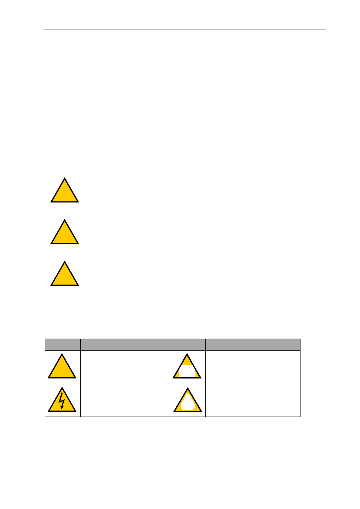
2.3 Dangers, Warnings, and Cautions
Alert Levels
There are three levels of alert notation used in our manuals. In descending order of importance, they are:
DANGER: Identifies an imminently hazardous situation which, if not
avoided, is likely to result in serious injury, and might result in fatality or
severe property damage.
WARNING: Identifies a potentially hazardous situation which, if not avoided,
will result in minor or moderate injury, and might result in serious injury, fatality, or significant property damage.
CAUTION: Identifies a potentially hazardous situation which, if not avoided,
might result in minor injury, moderate injury, or property damage.
Alert Icons
The icon that starts each alert can be used to indicate the type of hazard. These will be used
with the appropriate signal word - Danger, Warning, or Caution - to indicate the severity of the
hazard. The text following the signal word will specify what the risk is, and how to avoid it.
Icon Meaning Icon Meaning
This is a generic alert icon. Any
specifics on the risk will be in
the text following the signal
word.
This identifies a hazardous electrical situation.
This identifies a hazardous entanglement situation.
This identifies a fire risk.
32 LD-250 Platform User's Manual 20472-000 Rev D
Page 33
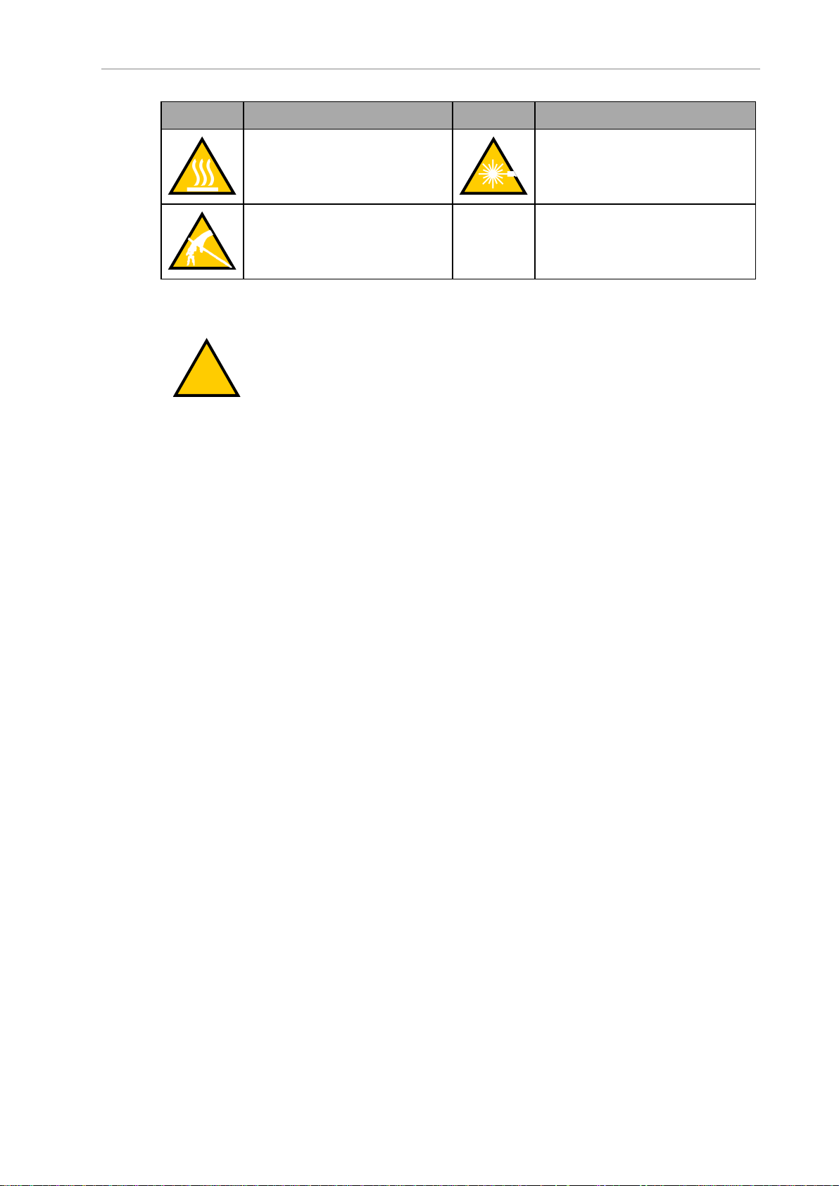
Chapter 2: Safety
!
Icon Meaning Icon Meaning
This identifies a hazardous
burn-related situation.
This identifies a hazardous ESD
situation.
Falling Hazards
This identifies a laser emitter eye
damage situation.
WARNING: PERSONALINJURYORPROPERTYDAMAGERISK
The AMR can cause serious injury to personnel or damage to itself or other
equipment if it drives off of a ledge, such as a loading dock, or down stairs.
Physical Barriers
Use physical barriers together with logical barriers (map restrictions) to prevent the AMR from
approaching any fall hazard that is within its operating area. Such hazards include:
l
The edge of a loading dock or ramp.
l
Entrance to downward stairs.
l
Any other vertical drop that exceeds the AMR's maximum step height.
Required characteristics of physical barriers are:
l
Strength—The barrier must be attached to a solid wall or floor and should be strong
enough to stop a fully-laden AMR traveling at maximum speed.
l Continuity—The barrier must extend around the hazard completely.
l
Visibility—Mark all physical barriers to make sure that the AMR's safety and navigation laser can detect them easily. Barriers must extend above and below the laser's
sensing plane, particularly if the floor is not flat.
Logical Barriers
In addition to physical barriers, create forbidden areas or lines on the workspace map to prevent AMRs from closely approaching a fall hazard. These restrictions must be continuous so
that the AMR cannot plan a path around the logical barrier.
You can also use the configuration parameters FrontPaddingAtSlowSpeed and FrontPad-
dingAtFastSpeed to increase the AMR's safety clearances. This causes the AMR to decelerate
as it approaches a hazard. See Fleet Operations Workspace Core User's Manual (Cat. No. I635).
20472-000 Rev D LD-250 Platform User's Manual 33
Page 34

2.4 User's Responsibilities
!
!
Special Information
This manual uses the following typographic styles to identify specific types of information:
IMPORTANT: Information to ensure safe use of the product.
NOTE: Information for more effective use of the product.
Additional Information: Offers helpful tips, recommendations, and best prac-
tices.
Version Information: Information on differences in specifications for different
versions of hardware or software.
2.4 User's Responsibilities
You are responsible for continuous safe use of the AMR.
WARNING: PERSONALINJURYRISK
It is the end-user's responsibility to perform a task-based risk assessment and
to implement appropriate safety measures at the point of use of the AMR in
accordance with local regulations.
WARNING: PERSONALINJURYORPROPERTYDAMAGERISK
It is the end-user's responsibility to make sure that the AMR design and implementation complies with all local standards and legal requirements.
Safe use of the AMR requires that you:
l
Read the installation and operation instructions, in addition to the Mobile Robot
LDSafety Guide (Cat. No. I616), before using the AMR.
l
Make sure that the environment is suitable for safe operation of the AMR.
Two or more AMR's require a Fleet Management appliance unless you confine and operate each AMR in a separate workspace. See: Fleet Operations Workspace Core User's
Manual (Cat. No. I635).
l
Make sure that any person working with or near an AMR is trained, and has read the
Mobile Robot LDSafety Guide (Cat. No. I616) for safe AMR operation.
l
Mechanically maintain and service AMRs for proper operation of all control and safety
functions.
Understanding Electrical Hazards
WARNING: ELECTROCUTIONRISK
The docking station has ACpower inside. Docking station covers are not interlocked.
34 LD-250 Platform User's Manual 20472-000 Rev D
Page 35

Chapter 2: Safety
!
l
Do not use power extension cords with the docking station unless properly rated.
l
Never access the AMR's interior while it is attached to a charger.
l
Immediately disconnect the battery after you open the battery compartment door.
Avoid shorting the battery terminals.
l
Do not use any charger not supplied by OMRON.
l
If the AMR comes into contact with any liquid:
o
Power off the AMR.
o
Clean off as much liquid as is possible.
o
Allow the AMR to air dry thoroughly before restoring power.
o
Contact your local OMRON Support if you suspect that liquid has penetrated the
skins or contaminated the AMR's interior.
Magnetic Field Hazards
The docking funnel creates a strong magnetic field. This component is located on the underside of the LD-250. Persons using medical implants should not approach the docking funnel.
WARNING: MAGNETIC FIELD - MEDICAL IMPLANT RISK
Magnetic fields can be hazardous if you have a medical implant. Keep a minimum of 30 cm away from the LD-250 when its underside is exposed during
maintenance procedures.
Qualification of Personnel
You must make sure that all personnel who work with or around AMRs have appropriate
training and have a thorough working knowledge. Provide the necessary additional training
for all personnel that work with the system.
As described in this manual, and the Mobile Robot LDSafety Guide (Cat. No. I616), you should
allow only skilled persons or instructed persons to do certain procedures:
l
Skilled persons have technical knowledge or sufficient experience to enable them to
avoid either electrical or mechanical dangers.
l
Instructed persons are adequately advised or supervised by skilled persons to enable
them to avoid either electrical or mechanical dangers.
For example, replacing a battery is a task for a skilled person, while an instructed person can
complete the task of charging a battery.
All personnel must observe industry-prescribed safety practices during the installation, operation, and testing of all electrically-powered equipment.
IMPORTANT: Before working with the AMR, every person must confirm that
they:
20472-000 Rev D LD-250 Platform User's Manual 35
Page 36

2.4 User's Responsibilities
!
l
Have the necessary qualifications and training.
l
Have received the manualss (both this user’s manual, and the Mobile Robot
LDSafety Guide (Cat. No. I616)).
l
Have read the manuals.
l
Understand the manuals.
l
Will work in the manner specified by the manuals.
Payload Movement and Transfer
A typical AMR application uses a payload structure to transport objects within a facility. For
example, the AMR might pick up and carry a crate of engine parts from one conveyor belt
then deliver it to another conveyor belt.
During movement and transfer, you must actively monitor and confirm the transfer operation
to make sure that it completes successfully. If any operation fails, a fail-safe interlock must trigger an AMR E-Stop condition. An E-Stop condition prevents the AMR from moving until you
resolve the problem and confirm that it is safe to restart operations.
Your facility should provide such fail-safe interlocks between the AMR and any facility equipment with which it interfaces. After you attach your payload to the AMR, verify the correct
operation of the fail-safe interlock as part of your risk assessment.
Configurable Warning Buzzer
The LD-250 has a configurable warning buzzer. Configure this buzzer as appropriate for the
facility in which the AMR operates. By default, the buzzer sounds when the AMR is moving
in any direction other than forward motion.
You can also configure the buzzer to activate in other specific situations, or to operate continuously whenever the AMR moves. The buzzer does not have a volume control and you
should make sure it is audible in all workspace locations, particularly where ambient noise
levels are high.
MobilePlanner provides the buzzer configuration parameters described in Table 2-1.
CAUTION: PERSONAL INJURY RISK. Changing buzzer parameter values
might make the AMR unsafe and affect compliance with safety standards.
Refer to the applicable safety standards for your locale before you change any
parameter values.
Table 2-1 Buzzer Parameters
Parameter Default Setting
safetyBuzzerDisable_All 0 (Disabled)
safetyBuzzerDisable_Safedrive 0 (Disabled)
safetyBuzzerDisable_FwdMotion 1 (Enabled)
safetyBuzzerDisable_AllMotion 0 (Disabled)
36 LD-250 Platform User's Manual 20472-000 Rev D
Page 37

Chapter 2: Safety
!
!
Fleet Management
When two or more AMRs operate in the same workspace they might not be able to accurately
detect other AMRs, or to precisely determine the dimensions of other AMRs. This might result
in collisions or deadlocks where both AMRs must halt and wait for human intervention.
To manage and administer multiple AMRs in the same workspace, you must use a EM2100
appliance configured as a Fleet Manager, running the Fleet Operations Workspace (FLOW) software.
Regardless of its safety laser type, an individual AMR always operates safely and within specifications. If a fleet includes different LD-series AMRs that also have different types of safety
laser, all AMRs always operate safely. However, a fleet that includes different LD-series AMRs
(such as, LD-60, LD-90, LD-250, etc) that have the same type of safety laser (i.e OS32C) will
have improved fleet performance that meets specifications.
The Fleet Manager controls AMRs over a wireless network (WiFi), reducing the risk of AMR
collisions by sharing the information between all AMRs in the fleet. The shared information
includes:
l
Dynamic X, Y, position and heading (velocity and direction of travel) of the AMR.
l
AMR size (including payload structure).
l
Path planning information (the individual AMR's intended route).
AMRs factor this data into their obstacle avoidance algorithm.
IMPORTANT: Fleet Manager is not an interlocked method of collision prevention. It is your responsibility to implement interlocked methods of collision
prevention where necessary.
For operational redundancy and fail-over you can add a second EM2100 appliance. See the
Fleet Operations Workspace Core User's Manual (Cat. No. I635) for more information.
2.5 Environment
General Environmental Conditions
Make sure that the LD-250‘s operating environment remains safe for the LD-250.
CAUTION: PERSONALINJURYORPROPERTYDAMAGERISK
Improper path planning can result in personal injury or property damage.
WARNING: PERSONALINJURYORPROPERTYDAMAGERISK
An AMR can be unsafe if operated under environmental conditions other than
those specified in this manual.
l
Environmental Hazards—There are areas where it is unsafe for the LD-250 to operate,
for example, steep ramps (greater than 1:12 or 4.7° unloaded), loading docks, or shelves.
20472-000 Rev D LD-250 Platform User's Manual 37
Page 38

2.5 Environment
!
Provide physical barriers that the LD-250 can detect accurately with its scanning laser
so that it does not attempt to drive near the hazard. Be aware that in addition to being
easily detectable, a barrier must be strong enough to resist a fully-loaded AMR traveling
at speed.
l
Restricted Areas—You can also use map features such as preferred lines and forbidden
zones to keep AMRs within their designated area of operation. See the Fleet Operations
Workspace Core User's Manual (Cat. No. I635) for information about editing your workspace map.
While you can use either or both physical barriers and map features to keep AMRs within
their designated workspace, OMRON recommends that you always install physical barriers
where there is a risk of damage or personal safety.
Public Access
The LD-250 is designed to operate in indoor industrial environments. You must deploy it only
in applications where you anticipate and mitigate potential risks to personnel and equipment.
OMRON does not intend the LD-250 for use in uncontrolled areas without risk analysis. For
example, in areas open to general public access. Use of the LD-250 in such areas requires that
you deploy additional safety measures not described in this manual. For assistance, contact
your local OMRON Support.
Clearances when Operating
Side Clearances
The LD-250 is designed to operate in environments that contain doors, passageways, or other
constrained areas that are wide enough for it to traverse.
However, you must maintain adequate side clearance (free space) on both sides of the AMR so
that it cannot trap a person against a wall or other fixed object. Consult the applicable
Autonomous Vehicle and Robotics operating standards for your locale.
An AMR must often maneuver close to machinery, conveyors, or other fixed objects. In such
cases, operating standards usually allow an exception to side clearance requirements.
For more information, see: Side Clearance on page 114, and refer to the Fleet Operations Workspace Core User's Manual (Cat. No. I635) for information about software parameters that you
can use to control the LD-250's front and side clearance zones.
Clearances During Rotation
The LD-250 generally travels in a forward direction and cannot do path planning in the
reverse direction. It reverses only if you create a MobilePlanner macro task that requires it to
move in reverse. Otherwise, the LD-250 only reverses onto its docking station to recharge. To
change direction, the LD-250 rotates on its center of rotation (turns in place). However, when
the LD-250 rotates, obstacles in its path do not trigger a safety system event.
The LD-250's Light Discs display a distinct turn signal pattern when it rotates. For more
information, see:Indications Provided by Light Discs Light Outputs on page 127.
CAUTION: PERSONALINJURYRISK
Personnel who work with or around the AMR should not stand close to the
AMR when it is rotating with no forward motion.
38 LD-250 Platform User's Manual 20472-000 Rev D
Page 39

Chapter 2: Safety
Docking Clearances
You should set a 1.5 m (4.9 ft) distance between docking goals and physical docks to allow sufficient room to maneuver around other AMRs when docking.
Obstacles
Before an AMR enters a high-traffic areas, you must take appropriate precautions to alert
people working in those areas:
l The LD-250 provides active warning features such as a warning buzzer, speech syn-
thesis, and warning indicator lights.
l The LD-250 Core provides user ports that enable you to add warning indicators to your
payload structure. See: Indications Provided by Light Discs Light Outputs on page 127.
If high-traffic areas include other moving vehicles such as fork-lift trucks or autonomous moving machines, consider adjusting the AMR's operating parameters to reduce the risk of a collision. You can do this by:
l
Editing the workspace map to include map features that restrict the AMR's local operation such as restricted entry zones, slow speed zones, or preferred lines.
l
Editing the AMR's operating parameters to restrict its global operation, such as redu-
cing its maximum speed or minimum approach distance.
For more information, see: Fleet Operations Workspace Core User's Manual (Cat. No. I635).
Emergency Stops that are Initiated by AMR Safety Lasers
Under certain conditions, the AMR safety systems might cause an emergency stop.
For example, an AMR reacts to obstacles in its path by slowing and, if necessary, stopping
safely. It then either plans a new path around the obstacle or (if the obstacle has moved)
resumes its original path. The safety laser initiates an emergency stop that occurs any time the
laser detects unavoidable obstacles that are immediately in the AMR's path, but only when the
AMR is moving faster than 300 mm/second.
During the emergency stop, a controlled deceleration slows the AMR up to the maximum
allowable rate and then applies the brakes.
NOTE: An emergency stop initiated by an intrusion into the safety laser's protection field differs from pressing an E-Stop button. After you press an E-Stop button, you must first resolve the problem and then manually resume AMR
operation. See: What to Do in an Emergency on page 30.
Other circumstances might cause an emergency stop, such as:
l
Pushing the AMR in reverse faster than 300 mm/second might cause an over-speed
fault that requires manual intervention to clear.
l
User-supplied sensors connected to the LD-250 Core's User Interface port. User Interface
(Brake and E-Stop) on page 103.
After the AMR comes to a complete emergency stop caused by laser protection zone intrusion,
it waits a minimum of two seconds before it resumes operation. No user intervention is necessary and the AMR does the following:
20472-000 Rev D LD-250 Platform User's Manual 39
Page 40

2.6 Intended and Non-intended Use
!
1.
Verifies that there is adequate space to maneuver.
2.
Plans a local path deviation around the obstacle and resumes its task.
However, if the AMR cannot avoid the obstacle, the following outcomes might occur:
1.
The AMR identifies and plans a revised path to its goal. (This might cause the AMR to
turn around and move in a different direction.)
2.
Fail the current job and wait for Fleet Manager to assign a new job.
3.
If no alternate path is possible, signal an error state to the Fleet Operations Workspace
software and wait for user intervention.
Safety System Overspeed Faults
The LD-250 has an independent safety system that uses a dual complex programmable logic
device (CPLD) to redundantly monitor its velocity. This device makes sure that the AMR
always operates within the speed limits specified by safety standards DIN EN 1525 and ANSI
B56.5.
Both safety standards specify that an AMR's velocity is limited to less than 300 mm/second
when traveling in any direction that is not scanned by its safety laser.
If the AMR operates outside this specified velocity limit, its CPLDs report a Channel 1 or Channel 2 system fault to its operating firmware and begins an emergency stop (ESTOP) sequence.
In autonomous operation, the fault triggers the AMR's motion controllers to execute a controlled stop.
If motion is already disabled (for example, an E-Stop button is engaged) and you override the
brake release, the safety system cannot stop the AMR. This is because power to the drive
motors is already cut off. After you resolve the error condition the safety system stops reporting
safety fault to the motion controllers and the normal start-up process begins.
Motion control configuration parameters in the ARAM software (such as AbsoluteMaxTransVel) limit the maximum allowable velocities. Use MobilePlanner to modify the
value of these parameters. Refer to the Fleet Operations Workspace Core User's Manual (Cat. No.
I635).
2.6 Intended and Non-intended Use
Intended Use
The LD-250 is designed to operate in indoor industrial environments. In general, if a wheelchair user can safely and easily navigate the environment (open, and mostly flat with only
gentle inclines and wide doorways), then it is navigable by an LD-250.
DANGER: PERSONALINJURYRISK
There is risk of serious injury by crushing if the AMR tips over as a result of
improper operation on inclines that do not comply with the operating specifications.
The following guidelines apply:
40 LD-250 Platform User's Manual 20472-000 Rev D
Page 41

Chapter 2: Safety
l
Floor—Clean and dry floors that you sweep regularly and routinely keep free of debris,
dust, and liquids.
l
Typical Inclines—The LD-250 is intended to operate in a workspace that has a mostly
flat floor. If the workspace includes inclined areas, OMRON recommends a gentle
incline typical of wheelchair ramps. Be aware that the payload structure and any loads
transported can:
l
Reduce the AMR's ability to traverse an incline.
l
Change its operating center of gravity (CG).
l
Inclines (Ramps)—With a properly designed and stable payload, the LD-250 can operate on ramps at full payload capacity. However, extended periods of operation on
ramps will affect battery duration and speed is limited to 600 mm/second on inclines
such as ramps. Operational recommendations are:
Slope Payload Restriction Speed Limit
1.7° (3% grade) No restriction No restriction
3° slope 200 kg 600 mm/s
4.75° (1:12 slope, typical wheelchair ramp) 165 kg 600 mm/s
l
Temperature—5 to 40°C, with a recommended humidity range of 5% to 95%, non-condensing. Operating the LD-250 at high or low ambient temperatures (particularly with a
full payload and high speeds) can cause the battery to exceed its operating temperature
limits. If this happens, you are notified by escalating software messages as follows:
o
The battery is approaching a high or low temperature limit. Change the LD-250's
operating conditions so that the battery can return to within its ambient temperature limits.
o
The battery has exceeded an initial limit, the LD-250 continues to operate but
charging is deferred until the battery has returned to within its ambient temperature limits
o
The battery has exceeded its temperature limits and the LD-250 will shut down
immediately.
The LD-250 has an ingress protection rating of IP20 and is not liquid-proof. Keep floors dry
because liquids might get into the AMR. Damp, dusty, or greasy floors might also cause its
drive wheels to slip or skid. Such traction problems can affect both braking and accuracy.
Non-Intended Use
When deploying an AMR, anticipate potential risks to personnel and equipment. OMRON
intends the LD-250 for use in a carefully controlled and managed environment with restricted
access granted only to trained personnel.
You should conduct a risk analysis before you deploy the LD-250 in other environments. For
example, deployments in areas that are open to general public access such as retail stores.
Application of the LD-250 in such areas generally requires additional safety measures.
OMRON does not intend the LD-250 for deployment in environments that contain:
20472-000 Rev D LD-250 Platform User's Manual 41
Page 42

2.7 Battery Safety
l
Hazardous (explosive or corrosive) atmospheres.
l
Ionizing or non-ionizing radiation.
l
Extreme heat or humidity.
l Floors that are damp or have any standing water.
IMPORTANT: The LD-250 is not waterproof. Keep all floors dry. Dampness can
cause drive wheels to slip, affecting both braking and navigation.
In addition, OMRON does not intend the LD-250 for deployment in the following environments:
l
Life-support systems.
l
Residential installations.
l
Mobile installations, including moving floors or any type of land vehicle, watercraft, or
aircraft. (LD-250 navigation is assisted by a gyroscope embedded in the LD-250 Core.
For accuracy, the gyroscope requires a stationary environment).
IMPORTANT: Observe all instructions for operation, installation, and maintenance provided in this manual and in the Mobile Robot LDSafety Guide (Cat.
No. I616).
Non-intended use of an LD-250 can:
l
Cause injury to personnel.
l
Damage the LD-250 or other equipment.
l
Reduce reliability and performance.
If there is any doubt concerning the application, ask your local OMRON Support to determine
whether it is an intended use.
LD-250 Modifications
OMRON recognizes that customers or integrators make modifications to the LD-250 to adapt it
to a specific application. When doing so, make sure that:
l
You use the LD-250 Core's User Interface connection to include appropriate safety
devices into the LD-250's integrated safety systems.
l
The modification causes no hazardous sharp edges, corners, or protrusions and does
not extend further than the LD-250 footprint. (This might affect the safety zones.)
l
There is no reduction in functionality.
l
All safety features (such as lasers and brakes) are functional and operate within the specifications determined by local standards for AMRs.
2.7 Battery Safety
The LD-250 requires one lithium ion battery. Use only the battery of the correct model number
supplied by OMRON. The FLOW software determines whether the battery is the correct type
42 LD-250 Platform User's Manual 20472-000 Rev D
Page 43

Chapter 2: Safety
!
for the LD-250.
Effective April 1, 2016, IATA regulations (UN 3480, PI 965) require that air-shipped lithium ion
batteries must be transported at a state of charge not exceeding 30%. Fully charge the battery
immediately upon receipt to avoid total discharge. (The battery might arrive fully charged if it
is not shipped by air.)
CAUTION: BATTERYDAMAGERISK
Fully charge the battery immediately after delivery. Failing to do so might
cause the battery to discharge below a usable state, requiring its replacement.
See also: Battery Shipment on page 47.
Battery Safety Precautions
l
Store batteries upright and within the following temperature range:
l
One month: +5 to 45°C (41 to 113°F)
l
One year: 20 to 25°C (68 to 77°F)
l
Batteries stored at temperatures greater than 54°C or less than -6°C must stabilize for an
hour or longer until within the nominal operating temperature before use.
l Never expose the battery to water. If the battery is leaking, submerge it in mineral oil
and contact your local OMRON Support.
l
In case of fire, use a type ABC or BC dry chemical extinguisher.
Battery Maintenance
Every six months:
l Inspect the battery for damage or leaks.
l Connect the battery to a charger and allow it to fully balance all cells.
2.8 Additional Safety Information
Contact your local OMRON Support for other sources of safety information.
Mobile Robot LDSafety Guide (Cat. No. I616)
The Mobile Robot LDSafety Guide (Cat. No. I616) is included with your LD-250 and provides
detailed information about safe operation of your LD-250. It also provides resources for information about relevant standards.
2.9 Disposal
Dispose of in accordance with applicable regulations.
20472-000 Rev D LD-250 Platform User's Manual 43
Page 44

2.9 Disposal
Customers can contribute to resource conservation and protecting the environment by the
proper disposal of WEEE (Waste Electronics and Electrical Equipment). All electrical and electronic products should be disposed of separately from the municipal waste system via designated collection facilities. For information about disposal of your old equipment, contact your
local OMRON Support.
44 LD-250 Platform User's Manual 20472-000 Rev D
Page 45

This chapter describes how to set up your LD-250 and configure it for operation. It includes
information for optional features.
3.1 Overview of LD-250 Setup
Setup tasks consist of preparing the LD-250 for use by unpacking it and completing some
mechanical configuration such as installing the battery and the docking station. This includes
software procedures such as commissioning the LD-250 and communications tasks such as
configuring the LD-250 to use a wireless network.
Setup also includes creating and editing the workspace map that the LD-250 uses for navigation. This manual provides an overview of the map creation procedure, which is described
in detail in the Fleet Operations Workspace Core User's Manual (Cat. No. I635).
Preparing the platform might also include attaching your payload structure to the LD-250 and
then cabling the payload structure to the LD-250 Core for power, control, and data communications. The procedures described in this section assume that you independently complete and implement a design for your payload structure, using information and technical
specifications provided in this manual or obtained from OMRON consultants.
Tasks
Chapter 3: Setup
The tasks required to set up an LD-250 are:
l
Install the docking station. See Installing the Docking Station on page 58.
l
Fully charge the battery, either outside of or inside the LD-250.
l
Install the battery in the LD-250. See Installing the Battery on page 53.
l
Set up the wireless Ethernet for the LD-250. See Settings and Configuration on page 67.
l
Install your payload structure to suit your application. See Payload Structures on page 77.
l
Configure the AMR for your environment, so it can perform useful tasks.
This includes creating a workspace map that the AMR uses for navigation. Mapping is
described briefly in Create a Workspace Map on page 72 and in more detail in the Fleet
Operations Workspace Core User's Manual (Cat. No. I635).
You might require additional steps to attach and configure a payload structure, such as a robot
arm.
20472-000 Rev D LD-250 Platform User's Manual 45
Page 46

3.2 Transport and Storage
3.2 Transport and Storage
LD-250 Shipping and Storage
Ship and Store the LD-250 only under the conditions described in this section.
IMPORTANT: To prevent damage to electronic safety components, and to
ensure the safe operation of the LD-250, observe the shipping and storage instructions in this section.
Ship and store the LD-250 without its battery installed in:
l
A temperature-controlled environment, ranging from -20 to 60°C. The recommended
humidity range is 5% to 95%, non-condensing.
l
Its original shipping carton, which is designed to prevent damage from shock and vibration in transit. Protect the crate from excessive shock and vibration.
Use only a forklift, pallet jack, or similar device to move the shipping crate.
Keep the LD-250 in an upright position in a clean, dry area that is free from condensation. Do
not lay the crate on its side or any other non-upright position. This could damage the LD-250.
Figure 3-1 LD-250 Shipping Carton
The crate with pallet for the LD-250 has the following physical characteristics:
l Size:
o
132 cm wide (A)
o
105 cm high (B)
o
88 mm deep (C)
l
Shipping weight 196.6 kg.
l
Material - Corrugated fiberboard carton over a plywood and wood pallet.
46 LD-250 Platform User's Manual 20472-000 Rev D
Page 47

Chapter 3: Setup
l
Moisture resistance - none, unless wrapped with a waterproof sheet material. Do not
store the unprotected carton outdoors.
Battery Shipment
The LD-250 requires one OMRON-supplied lithium-ion battery, P/N 20452-000F
After installation, the AMR's software verifies the battery model and reports an error if the battery model is incorrect.
This section applies also to spare (backup) batteries.
Battery Operating Environment
Table 3-1 lists the battery operating temperature limits.
Table 3-1 Battery Low and High Temperature Limits
Battery Tem-
perature
Min °C Max °C
Action
5°C 40°C Nominal operating temperature range.
4°C 44°C Charging Limits - Battery charging is either shut off or cannot start.
-6°C 54°C Operating Limits - The Battery shuts down and there is no power to
the LD-250 Core.
The LD-250's software alerts you in the Operator Panel and the MobilePlanner software
UIwhen the Battery temperature is within 3°C of any limit.
It might take several hours for an overheated battery to cool sufficiently to resume operation or
begin charging.
Other considerations apply to these environmental limits:
l
Even at the nominal operating temperature limit, the battery might exceed its upper
charging limit temperature if the LD-250:
l
Is fully loaded.
l
Runs continuously for an hour or longer.
l
If the LD-250 is docked but the battery is too hot to charge:
l
Charging begins only when the battery temperature is within the operating range.
l
Only the docking station power LED illuminates, not the charge LED.
3.3 Before Unpacking
Carefully inspect all shipping boxes and containers for evidence of damage during transit. If
you observe any damage, request that the carrier’s agent is present when you unpack the shipment.
20472-000 Rev D LD-250 Platform User's Manual 47
Page 48

3.4 Unpacking Considerations
!
!
3.4 Unpacking Considerations
Before signing the carrier’s delivery sheet, compare the items received (not just the packing
slip) with your equipment purchase order. Verify that all items are present and that the shipment is correct and free of visible damage.
l
If the items received do not match the packing slip, or are damaged, do not sign the
receipt.
l
If the items received do not match your order, contact your local OMRON Support
immediately.
Retain the containers and packaging materials. You might require these items to settle claims
or, at a later date, to repack and relocate the AMR.
At a minimum the shipment contains:
l
A fully assembled LD-250.
l
Torx T30 driver for removing and replacing skins.
l
A Motor Lift tool part number: 20829-000 used for maintenance operations. This is
stored on board the LD-250.
WARNING: Do not attempt to lift the LD-250 off its pallet with a forklift or
other lifting device. Doing so might cause damage to the skins or under-body
components.
LD-250 Packaging
The LD-250 arrives in a carton secured by poly strapping to a pallet. Use only the pallet, and a
rated lifting device to move the shipment.
WARNING: PERSONALINJURYORPROPERTYDAMAGERISK
Follow all unpacking safety instructions and use appropriate tools and equipment. Failure to do so could result in personal injury or property damage.
The docking station and any options are packed in a separate carton positioned on top of the
main crate.
You require the following tools:
l
Forklift or pallet jack.
l
Safety box cutter. Do not use a open-blade knife such as a wallboard knife to cut into
packaging, you might damage the contents.
l
Eye protection, toe protection and gloves.
NOTE: Poly strapping might be under considerable tension. Hold it firmly as
you cut it.
48 LD-250 Platform User's Manual 20472-000 Rev D
Page 49

Description Image
A Main carton
B Docking station carton
C Docking station filler. (Might con-
tain options.)
D Unloading ramp
E LD-250 cover carton
F LD-250
G Shipping base, with wheel chocks
Chapter 3: Setup
H Protective filler (2)
I Foam corners (4)
J Plywood pallet
Unpack as follows:
1.
Make sure you have 1.5 m (5 feet) of clear working space around the pallet.
2.
Remove any weatherproof film or plastic sheet material and carefully cut the poly strapping with a sharp safety blade.
Figure 3-2 LD-250 Packaging
20472-000 Rev D LD-250 Platform User's Manual 49
Page 50

3.4 Unpacking Considerations
Figure 3-3 Unpacking the Docking Station and Accessories
1.
Referring to Figure 3-3, lift the main carton (A) upward and off the pallet.
2.
Remove any other accessories or options included in the filler (D). Locate one of the
included accessories, a T30 Torx driver (F), which you will need later to move the LD-
250.
3.
Remove the filler (D) and carton (C) containing the docking station, and then lift the
filler off the carton.
4.
Lift off the plywood ramp and set it aside temporarily.
50 LD-250 Platform User's Manual 20472-000 Rev D
Page 51

Chapter 3: Setup
Figure 3-4 Unpacking the LD-250.
3.
Referring to Figure 3-3, remove the protective filler (A) from each end of the pallet.
4.
Remove the four foam corners (B).
5.
Remove the corrugated fiberboard cover from the LD-250 (C). There is padding underneath to protect the top surface of the LD-250.
6.
Remove the padded wrapping (D) from the LD-250.
7.
Place the ramp in the end of the pallet, so that the two bolts in the pallet engage with
the holes in the ramp (E).
Before you can move the LD-250 off its pallet, you must first disengage the drive motors to
allow the drive wheels to move freely. To do this:
l
Remove both side skins so that you can access the drive train. Refer to: Remove and
Replace the Side Skins on page 179.
l
Disengage the drive wheel motors. Refer to: Engage and Disengage the Drive Wheel Motors
on page 148.
After you disengage the drive wheel motors, complete the unpacking procedure as follows:
20472-000 Rev D LD-250 Platform User's Manual 51
Page 52

3.4 Unpacking Considerations
Figure 3-5 Move the LD-250 Down the Ramp
1.
Referring to Figure 3-5, identify the safe push points (A) and (B) at the top edge of the
skins. Do not push lower down on the chassis because it might damage the skins or
other components.
2.
During shipping, the casters are prevented from movement by chocking strips on the
plywood package base. Be aware that it requires some effort to push the LD-250 over
these strips.
3.
Pushing from the top edge of the chassis using the push points (A) and steadying the
LD-250 at push points (B), carefully roll the LD-250 over the caster chocks and down
the ramp.
After unpacking, the next steps are:
l
Locate and install the battery, which is shipped separately. Refer to: Installing the Battery
on page 53.
l
Engage the drive wheel motors. Refer to: Engage and Disengage the Drive Wheel Motors on
page 148.
If you intend to proceed with commissioning the LD-250, read that section before you replace
the side skins or engage the drive wheel motors. Refer to: E-Stop and Safety Laser Commissioning
on page 173.
52 LD-250 Platform User's Manual 20472-000 Rev D
Page 53

Chapter 3: Setup
Battery Carton
The battery ships in a separate carton, not inside the LD-250. The battery box measures 311 x
540 x 457 mm. The battery weighs 19 kg. Locate the carton that contains the battery before continuing. Refer to the following figure.
Remove the battery from the carton. The battery has recessed lifting grips at either end of its
casing.
Install the battery as described in: Battery Installation Procedure on page 55.
3.5 Installing the Battery
Your LD-250 ships fully-assembled, excluding its battery. Air shipping regulations require that
the battery is packaged and shipped separately.
Access the Battery Compartment
Remove the LD-250's battery access skin to access the battery compartment door.
1.
Make sure that the LD-250 is powered off and that you press and lock one of its E-Stop
buttons.
2. Lift the latch (A)to detach the battery access skin, and lift the skin up and away from
the chassis (B).
Figure 3-6 Battery Shipping Carton
20472-000 Rev D LD-250 Platform User's Manual 53
Page 54

3.5 Installing the Battery
Figure 3-7 Remove the LD-250's Latched Battery Access Skin
3.
If necessary, use the security key (A) to unlock the battery compartment door and slide
the latch (B) to open the door. Observe the correct power cable routing as you open the
door.
54 LD-250 Platform User's Manual 20472-000 Rev D
Page 55

Chapter 3: Setup
!
Figure 3-8 Open the LD-250's Lockable Battery Door
Battery Installation Procedure
Make sure you install a fully-charged battery. The battery has recessed handles at each end for
easier lifting.
CAUTION: The battery weighs 19 kg. You might require a two-person lift to
handle it safely.
20472-000 Rev D LD-250 Platform User's Manual 55
Page 56

3.5 Installing the Battery
Figure 3-9 Recessed Handles for Lifting the Battery.
Figure 3-10 Correct Way to Lift the Battery
1.
Lift and slide the new battery into the battery compartment, with its connection ports
facing outward, toward the rear of the LD-250.
2.
Attach the battery power and data cables to the connectors at the rear of the battery.
56 LD-250 Platform User's Manual 20472-000 Rev D
Page 57

Chapter 3: Setup
Figure 3-11 Battery Cable Connectors, (A) Battery Charge Level, (B) Power Connector, (C) Data
Connector
3.
Close the battery compartment door to secure the battery in place and to prevent it from
shifting inside the compartment. Lock the door to prevent unauthorized access.
4.
Reinstall the LD-250's battery access skin and close the latch to secure it in place.
Do not power on the LD-250 until you have read the appropriate sections of this user's
manual.
3.6 Attaching the Payload Structure and Options
Attach the Payload Structure
At this point in AMR set up, attach your payload structure to the load-bearing bars located
beneath the top cover. OMRON provides only the mount point options described in: Payload
Dimensions and Design on page 80.
For information about power, data signal, and warning light connections, see: Connectivity on
page 93.
Attach LD-250 Options
If you ordered optional devices such as Acuity Localization that shipped separately, attach
them next. See: Optional Connections on page 91.
E-Stop Jumper on the LD-250 Core
The LD-250 Core requires either of the following attached to the E-STOP port (User Interface):
l
A jumper (part number 12730-000L).
l
User-supplied E-Stop button.
See: User Interface (Brake and E-Stop) on page 103.
20472-000 Rev D LD-250 Platform User's Manual 57
Page 58

3.7 Installing the Docking Station
Figure 3-12 Jumper Installed in the E-STOP port (User Interface)
NOTE: A different jumper (part number 13387-000) is required if you remove
the Operator Panel. See: Operator Panel (HMI)on the Payload on page 90.
Warning Light
Each AMR should have a visible flashing light, to warn people that the AMR is ready to move
or is moving. The exact implementation of this warning light depends on the design of your
payload. Use the LD-250 Core's Light Pole connector to power and control the warning light.
Make sure that the light remains visible under all operating conditions so that people can
always see it. Consider the design of your payload structure for warning light visibility, including when the AMR is transporting objects.
3.7 Installing the Docking Station
The docking station enables you to either manually or autonomously charge the LD-250's battery according to charging parameters that you set in MobilePlanner.
Install the docking station on a flat and level floor, in a location that is kept clear and is easily
accessible to AMRs. If you have more than one AMR, make sure that your map contains features such as parking spaces or queuing lanes to accommodate AMRs that are approaching
and leaving the charging areas.
The docking station's charging paddle is spring-loaded to accommodate slight variations in
the floor surface so that it engages with the AMR's charging funnel. You might need to adjust
the paddle’s height to ensure the desired clearance given the site’s floor conditions.
Considerations and requirements when installing the docking station are:
l
Secure the docking station through its base by threaded wood or concrete fasteners that
are appropriate for the substrate.
l
Additionally secure the docking station by the supplied bracket, fastened to an adjacent
wall. OMRON recommends both floor fasteners and the wall bracket for the LD-250. If
you cannot secure the wall bracket to a structural framing member with screws, use
heavy-duty toggle (butterfly) bolts in drywall. Do not use drywall plugs or anchors.
l
Temporarily use the docking station free standing (without fasteners) but attached to its
optional floor plate. Do this only for testing or experimenting with the location of your
docking stations. Secure the floor plate to the ground with strong fabric tape or lightduty fasteners.
58 LD-250 Platform User's Manual 20472-000 Rev D
Page 59

Chapter 3: Setup
l
Maintain 1.5 m of unrestricted space around the docking station to enable the AMRs to
maneuver. Obstacles close to the docking station might prevent successful docking.
l
Each docking station requires an adjacent wall power outlet. In highly-automated fleet
environments, consider using a redundant power supply.
IMPORTANT: If you do not use appropriate fasteners for sustained use, the
docking station might move during docking attempts, causing docking and charging failures. The maximum fastener diameter is 6 mm.
Docking Station Features and Parts
Figure 3-13 shows the exterior features and parts of the docking station. This figure does not
include the optional floor plate for free-standing installation.
Figure 3-13 Docking Station—Features and Parts
Table 3-2 describes the parts of the docking stations that are of interest to the user.
Table 3-2 Description of the Docking Station Features and Parts
Callout Description
A Power indicator LED (blue).
B Charging indicator LED (amber).
C Power inlet socket and power switch.
D Charging paddle. This is articulated and spring loaded to make good contact
with the AMR's charging contacts.
E Electrical contacts.
20472-000 Rev D LD-250 Platform User's Manual 59
Page 60

3.7 Installing the Docking Station
!
Callout Description
F Engagement roller. Guides the AMR's charging funnel onto the docking sta-
tion. This is a replaceable wear item.
G Manual charging connector. Use for charging spare batteries outside the AMR.
H Triangle target. The concave triangular back of the charging station provides a
laser reflection as a navigation cue for the AMR, enabling it to align itself accurately for charging.
Docking Station Requirements
The input circuit must provide overcurrent protection consisting of one or more circuit breakers, cartridge fuses, or Type S plug fuses of an acceptable type and rating in accordance with
National Electrical Code (NFPA 70) or other local standards.
CAUTION: FIRERISK
Use only on circuits provided with 10 A branch circuit protection in accordance with National Electrical Code, NFPA70, or other local electrical standards.
Operational requirements for the docking station are:
l
100-240 VAC, 50/60 Hz, 8 A (The docking station's power converter automatically
detects the source voltage.)
l
Ambient operating temperature: 5 to 40°C (41 to 104°F)
l
5% to 95% humidity, non-condensing
Required Tools and Fasteners
You require the tools and fasteners described in Table 3-3.
Table 3-3 Required Tools and Fasteners
Size Qty Description
#2 1 Cross-point (Phillips) screwdriver.
As required 1 Appropriate screwdriver, hex socket, or driver bit for the fasteners
that you supply.
3.175 mm (1/8
inch)
#10 (4.762 mm,
3/16 inch)
4 User-supplied toggle bolts (if not using screws into a framing mem-
ber)
4 User-supplied structural screws such as decking screws (f not using
toggle bolts into drywall)
M5 x 4 2 Stainless steel shoulder bolts and washers (supplied with the dock-
ing station.
Refer to Figure 3-14 for dimensions and fastener placement.
60 LD-250 Platform User's Manual 20472-000 Rev D
Page 61

Chapter 3: Setup
Wall Bracket Mount
1.
Fasten the docking station mounting bracket to a wall, with the bottom edge of the
bracket 98±20 mm above the floor.
2.
Fasten two shoulder bolts, each with a washer, into the rear of the docking station.
Tighten to 9 N·m.
Figure 3-14 Docking Station Dimensions
Callout Installation Method and Orientation
A Free standing, side view
B Free standing, top view
C Wall mount bracket
D Wall and floor mount, top view
E Wall and floor mount, side view
20472-000 Rev D LD-250 Platform User's Manual 61
Page 62

3.7 Installing the Docking Station
3.
Lower the docking station down, so the two bolts on the back of the docking station
slide into the bracket, securing the docking station to the wall.
Floor-mount, without Floor Plate
Screw the base of the docking station directly to the floor, using three user-supplied screws. For
dimensions of the available holes in the base, refer to Figure 3-14. OMRON recommends M5
self-tapping screws that are suitable for the substrate (wood, concrete, etc.)
Floor-mount, with Floor Plate (Temporary Use Only)
Use this method temporarily, and only for experimenting with docking locations. The docking
station does not ship with the floor plate attached, it is included in the same carton.
1.
Tip the docking station onto its back, so you can access the underside.
2.
Remove the two lowest screws (M4 x 12 flat-head), if present.
In the following figure, these screws are circled. The location of the third screw hole is
also circled.
3.
Attach the floor plate to the base of the docking station with three M4 x 12 flat-head
stainless steel screws.
Figure 3-15 Underside of Docking Station Foot, Showing Screw Locations
NOTE: These are the three locations for the M4 x 12 flat-head screws. Two are
already in place. Remove them before attaching the plate.
62 LD-250 Platform User's Manual 20472-000 Rev D
Page 63

Figure 3-16 Docking Station, Mounted on Floor Plate
Chapter 3: Setup
Figure 3-17 Docking Station Floor Plate Dimensions (units are mm [inches])
After you install the docking station:
1. Connect the power cord to the docking station and plug it in to a wall outlet.
2. Set the power switch to ON. The blue power LED indicator illuminates to indicate that
power is present.
See: Docking Station ACPower and Internal Fuses on page 163 if the blue LEDdoes not illu-
minate.
After you install the docking station, create a docking goal on the workspace map and configure your AMRs to use the dock for recharging. Refer to the Fleet Operations Workspace Core
User's Manual (Cat. No. I635).
20472-000 Rev D LD-250 Platform User's Manual 63
Page 64

3.7 Installing the Docking Station
Docking Station Contact Adjustment
The contacts on the docking station have five height settings to compensate for variations in
floor flatness at the docking station's location. The default is the highest setting, which should
be appropriate in most cases.
The height adjustment mechanism is on the underside of the docking station's floor plate,
shown in Figure 3-18.
Figure 3-18 Adjusting the Height of the Docking Station Contacts
Callout Description
A Spring loaded locking pin. (Pull out and quarter turn to lock it in the open
position, turn to release.)
B Highest adjustment (shipped default). Each notch adjusts the height by
4 mm.
C Lowest adjustment.
To test and adjust the height of the contacts:
1.
Using MobilePlanner, send the AMR to the dock to recharge.
2.
When the AMR reverses on to the dock, the operation should be smooth and quiet. If
you hear a noise, it is likely that the docking funnel is bumping the guide wheel.
3.
Disconnect the power cable and turn the docking station on its side.
4.
Push down on the charging paddle and hold it in place to take the tension off the
spring.
5. Pull out the pin (A) and slide it in the direction (C) to select a position slot (B) Adjust
the position of the paddle as shown in Figure 3-18. The height changes by 4 mm for
each notch.
Set the height of the contacts so that the roller is high enough to stay in contact with the LD250 as it is docking, but low enough so that the roller guides the paddle under the LD-250.
64 LD-250 Platform User's Manual 20472-000 Rev D
Page 65

3.8 Installing Software on your Windows PC
The LD-250's operating software is factory-installed. The accessories carton of your shipment
includes a USBflash drive that contains backup software copies and product documentation
files in PDF format.
To use the MobilePlanner software for set up tasks, install it on a Windows PC as described in
the Fleet Operations Workspace Core User's Manual (Cat. No. I635). That guide also provides
information about the SetNetGo Web UI, which you also use to perform additional setup tasks.
Some software is licensed for a short period to enable you to set up and configure the LD-250.
The software directs you to send an e-mail to OMRON. to obtain a term license. See the software documentation for more information.
Chapter 3: Setup
20472-000 Rev D LD-250 Platform User's Manual 65
Page 66

Page 67

Chapter 4: Configuration
This chapter describes the configuration steps for an LD-250.
Your LD-250 ships with firmware and on-board software installed (with temporary licenses).
Activate your licenses as described in the Fleet Operations Workspace Core User's Manual (Cat.
No. I635).
The LD-250 navigates using a digitized map of its workspace. You use the MobilePlanner client software on a Windows PCto create the map and download it to the LD-250. Map creation
is a required step before you can continue on to the Operation chapter of this manual.
You also use MobilePlanner to:
l
Configure the LD-250's operating parameters that control its operation.
l
Monitor and manually control the LD-250 in addition to scheduling autonomous operation.
For more information, see: Fleet Operations Workspace Core User's Manual (Cat. No. I635).
Use SetNetGo's Web interface for other configuration and set up tasks such as configuring network communication. You can access the SetNetGo interface from within MobilePlanner, or
through a direct connection to the LD-250. This enables ITpersonnel to easily configure network setting without needing to know how to access and use MobilePlanner. SetNetGo is also
accessible through a direct RJ-45 Ethernet cable connection to the LD-250's maintenance Ethernet port.
4.1 Settings and Configuration
Maintenance Ethernet Connection
To prepare an LD-250 for autonomous mobile operation you must first configure its network. If
you do not yet have wireless access, use the wired Ethernet port (Maintenance LAN) to connect MobilePlanner and set up the wireless network at a later time.
See also the Fleet Operations Workspace Core User's Manual (Cat. No. I635).
Default Network Settings
The LD-250's network has the following default configuration. Your network administrator
should review this information for compatibility with your existing network.
Network Feature Default Network Setting
Network Class Class C
Netmask for all ports 255.255.255.0
Permanent Maintenance Ethernet IP address 1.2.3.4
Configurable User LAN port IPaddress 10.10.10.10
Ethernet negotiation method Auto-MDIX
20472-000 Rev D LD-250 Platform User's Manual 67
Page 68

4.1 Settings and Configuration
Network Feature Default Network Setting
Network method Access Point (AP)
Identifier (SSID) Wireless Network
Security method Unsecured
LD-250 Default Network Settings.
Features of the Maintenance Ethernet Port
The following important considerations apply to the LD-250's Maintenance Ethernet port:
l
You cannot change its default address (1.2.3.4) or use that same address elsewhere on
the same network. Doing so could cause a network conflict, preventing proper and safe
operation of the AMR.
l
Do not connect the AMR's maintenance Ethernet port to your LAN. OMRON intends
that you use this port only for single connection for debugging or initial setup purposes.
The User LAN port provides an Ethernet connection for your LAN.
l Access to the SetNetGo Web UI is always enabled on this port. It does not require either
a password or a software license.
Consult your network systems administrator before using SetNetGo to change any default settings. See the Fleet Operations Workspace Core User's Manual (Cat. No. I635) for information abut
modifying network settings.
Configure the LD-250's Network
To configure the LD-250's network, you require:
l One Ethernet patch cable, minimum Cat-5 specification. This cable should be of suf-
ficient length that you can connect your PC to the AMR and work comfortably.
l An IP address in the range 1.2.3.0 to 1.2.3.255, excluding 1.2.3.4, which is the permanent
address assigned to the LD-250 Maintenance port
Use the following procedure to set up the network on the LD-250.
1.
Connect an Ethernet cable from the Maintenance Ethernet port on the LD-250 to an Ethernet port on your Microsoft Windows PC.
68 LD-250 Platform User's Manual 20472-000 Rev D
Page 69

Chapter 4: Configuration
Figure 4-1 Connecting an Ethernet Cable
Callout Description
A Minimum specification Cat 5 Ethernet Cable.
B Microsoft Windows PC with Ethernet LANport.
C LD-250 Maintenance Ethernet port (under a door in the rear skin).
2.
In the Windows desktop Open or Search box (or at a command prompt) type the following command and press Enter:
ncpa.cpl
This command opens the Network Connections screen:
Figure 4-2 Network Connections Screen.
3.
Right-click on the Ethernet N or LAN Connection.
4.
Click Properties, and then double-click the Internet Protocol Version 4 connection item
to open its Properties window.
20472-000 Rev D LD-250 Platform User's Manual 69
Page 70

4.1 Settings and Configuration
Figure 4-3 Dialogs for the Ethernet Properties
5.
Click the radio button next to Use the following IP address.
6.
Enter 1.2.3.X as the IP address and 255.255.255.0 as the Subnet mask.
(Where x is any number 1 through 255 excluding 4.)
7.
Click OK twice to exit both Properties dialogs, and then close the Network Connections
screen.
Test the TCP/IP port connection by accessing the SetNetGo Web UI:
1.
Open a Web browser on the PC and enter https://1.2.3.4 as the URL.
2.
If prompted to accept security certificates, confirm that you accept them.
3.
Verify that the SetNetGo Web UIopens.
Setting Up Wireless Ethernet
A single LD-250 can operate without a wireless network. For example, if it is the sole AMR in
a workspace and it does not need to share the workspace with other AMRs. However, if you
have more than one AMR sharing the same workspace, you must manage them as a fleet.
Fleet management requires continuous wireless network access. For more information, see:
Fleet Manager for Multi-AMR Coordination on page 185.
Before you configure wireless Ethernet on your LD-250, contact your network administrator to
confirm the IP, radio, and security settings.
Use one of the following methods to access the SetNetGo Web UI:
l
Use the SetNetGo tab in the MobilePlanner software. See the Fleet Operations Workspace Core User's Manual (Cat. No. I635).
l Open a Web browser on your PC and enter the URL: https://1.2.3.4, to connect directly to
the SetNetGo Web UI on your LD-250. This enables your network administrator to set
up the network for you, without using a licensed instance of MobilePlanner.
Set Up a Wireless Network on the Management Interface
To set up the wireless network, you need the following resources. Discuss this with your network administrator and use the following the table as a worksheet to gather the necessary
data.
Description Your Data
A static IP address
The netmask for your network
Gateway
DNS server(s)
SSID for the AMR network
Mode for the network The only option is: Infrastructure
70 LD-250 Platform User's Manual 20472-000 Rev D
Page 71

Chapter 4: Configuration
Description Your Data
Radio Mode 802.11a/b/g/n/ac
Channel Set
Wireless Watchdog IP Address
Wireless Watchdog Max Count (0 disables)
Security encryption Disabled WEP (64 or 128-bit)
TKIP/RC4 CCMP/AES TKIP/CCMP/AES
Authentication Method (OPENis not
recommended)
OPEN WPA-PSK WPA2-PSK
EAP-TLS PEAP-MSCHAPv2
Figure 4-4 Worksheet: Data required to Configure the Wireless Network
After you connect to the SetNetGo Web UI, navigate to the Management Interface:
1.
Click the Network tab.
2.
Click Management Interface in the sidebar.
3.
Follow the steps in the interface to enter the network data.
4.
Click Apply for your changes to take effect.
Wireless Signal Availability
Your wireless network should provide constant service throughout the workspace. Consider
the following network resource requirements:
l
Signal Availability—If you have an AMR fleet, constant access is an operational requirement. For a single or segregated AMR's, partial signal cover might be acceptable in
workspace areas where you do not need to send commands or receive status from the
AMR.
l
Signal Strength—A signal of >=-40 dBm is the ideal WiFi signal strength, -60 dBm is
the recommended minimum.
OMRON recommends that you use wireless network industry best practices to conduct a comprehensive workspace survey and test your wireless service.
The greater the number of AMR's in your fleet, the more wireless resources they consume. For
more information about wireless resource requirements see: Fleet Operations Workspace Core
User's Manual (Cat. No. I635).
Bandwidth Considerations
All devices that access a Wireless network consume its bandwidth. Use a dedicated network to
restrict wireless network access to AMRs and use security to prevent other devices from accessing the network.
Typical bandwidth consumption for a fleet is an average 50 Kbps per AMR. This increases
when you connect multiple AMR's to an EM2100, and actively manage them with
20472-000 Rev D LD-250 Platform User's Manual 71
Page 72

4.2 Create a Workspace Map
MobilePlanner. Bandwidth consumption might increase or decrease depending on the types of
commands and debugging tools that you enable in MobilePlanner.
However, the bandwidth consumption is unlikely to exceed 500 Kbps per AMR (0.5 Mbps). A
value of 0.5 Mbps per AMR is within the capabilities of most wireless access points (>=54
Mbps). If you have multiple access points with overlapping cover, this number is less of a concern.
Payload structures might affect your bandwidth requirements, such as if the AMR supports a
video camera that streams digital video through the AMR’s wireless interface. Based on these
possibilities, the bandwidth usage varies by application.
For more information about fleet wireless resources, see the EM2100 Installation Guide (Cat.
No. I634).
4.2 Create a Workspace Map
Map Creation Overview
You connect a joystick to the AMR to create the map. The process is described in detail in the
Fleet Operations Workspace Core User's Manual (Cat. No. I635). See: Joystick Controls and Description
on page 138.
When you use the LD-250 to create a map:
l Put a minimal payload, or preferably no payload on the AMR.
l Map at low linear and rotational speed and acceleration.
This will make sure that wheel slip is minimal and the map is more accurate.
If the workspace has open stairwells, docks, ledges or other vertical drops, make sure that you
surround such areas with physical barriers. Barriers must be detectable by the safety laser's
scanning plane, which is at a height of 190 mm from the floor. Do this before you begin mapping the workspace.
Map Description
Before you can use your LD-250, you must create a digitized map of its designated workspace.
The map records the shape and location of permanent physical features in the workspace.
These features are walls, corners, doors, columns and large immovable fixtures such as
machines or fixed industrial shelving.
Moving objects (such as fork-lift trucks and carts) or transient objects (such as pallets loaded
with finished goods) do not provide useful mapping data. Erase such objects from the map
after you create it.
Map Laser Scan
The LD-250's Safety Scanning Laser scans the workspace to create the map. The laser scans
only a narrow horizontal plane, parallel to the floor. The scanning plane height is 190 mm
above the floor, so the laser cannot detect physical features above or below this plane, or features that are out of operating range and resolution. This means that some features are not
recorded on the map such as:
72 LD-250 Platform User's Manual 20472-000 Rev D
Page 73

Chapter 4: Configuration
l Overhanging objects, such as:
o
cupboards that are attached to a wall, but at a low height so that there is clear
space underneath.
o
Tables with narrow supporting legs.
l
Low-lying objects such as a column plinth that is below the scanning plane or a pallet
that contains no cargo.
Map Creation and Editing
You use the MobilePlanner software to create and then edit your workspace map. You can add
virtual elements to the map that modify the behavior of an AMR. Examples of virtual elements include:
l
Forbidden lines and zones—Areas in the workspace where an AMR cannot enter or
move across.
l
Speed zones—Areas where an AMR must travel within a specified speed range.
l
Preferred lines—Paths that you specify on the map which the AMR must consider
when planning the most efficient path to follow autonomously to its goal.
l
Preferred-direction zones—Areas where the AMR will prefer to travel in a specified direction. In a typical preferred direction zone (such as a narrow hallway) there is an
opposite direction that you want the AMR to avoid. Use a preferred-direction zone to
keep the AMRto the preferred side of a hallway. The AMRis able to travel on the alternate side of the zone if the preferred side is blocked.
Regardless of the constraint specified by any virtual element on the map, the AMR always
operates according to its safety protocols. For example, when following a preferred line the
AMR still responds to, and avoids, dynamic obstacles.
Maps contain a variety of goals, routes, and tasks that comprise the destinations and activities
of the AMR in the workspace. Refer to the Fleet Operations Workspace Core User's Manual (Cat.
No. I635) for information about editing a map.
Mapping Tasks
Mapping includes the following tasks:
l
Consider installing the docking station before you create a map file. This helps you to
place the dock goals when you edit and customize the map.
l
Drive the LD-250 with the joystick to make a workspace scan. We recommend that you
drive it to and position it onto its automated docking station to prepare for the next
steps.
l
Load that workspace scan into the MobilePlanner software on your PC to create and
edit a digitized map.
l
Add job-related features such as routes, goals, and docks to your map. For example in
MobilePlanner, you click Working With Map Files and then Editing a Map File. In the
editing section, click Using the Drawing Tools and then Adding Goals and Docks.
See the Fleet Operations Workspace Core User's Manual (Cat. No. I635) for more information.
20472-000 Rev D LD-250 Platform User's Manual 73
Page 74
4.3 Acceleration, Deceleration, and Rotation Limits
!
l
Transfer the working map to the Fleet Manager, or back to the LD-250, if you have only
one AMR, to perform autonomous mobile actions.
The Fleet Manager automatically downloads the new map to each AMR in your fleet as
soon as the AMR becomes idle.
l
Save map collections and deploy your AMR in any of your workspaces by selecting the
appropriate map file.
4.3 Acceleration, Deceleration, and Rotation Limits
For safety, an AMR has default limits on its maximum linear and rotational acceleration, deceleration, and speed. You can change the parameters that control these limits. However, changing the limits might affect the AMR's stability, depending on the center of gravity (CG) of the
combined LD-250 and its payload.
CAUTION: PROPERTYDAMAGE RISK
If you change the value of the AbsoluteMaxTransVel parameter, re-commission
the AMR before putting it into service.
If your payload’s center of gravity is not within the guidelines provided in Center of Gravity
(CG) on page 86, you might need to adjust the Absolute Movement Maximums parameter values in the MobilePlanner software.
For payload applications where you cannot easily reduce the size and weight of the payload or
if the AMR’s CG is not within the recommended limits, contact your local OMRON Support.
Table 4-1 lists the Absolute Movement Maximums parameter limits and defaults. The first
four parameters have the least significant impact on the AMR‘s stability. All *Accel and *Decel
parameters have a significant impact. If the payload is asymmetric, you might need to adjust
the value of AbsoluteMaxRotVel.
Table 4-1 Absolute Movement Maximums Parameters
Parameter Default Min Max Your Min Your Max
AbsoluteMaxTransVel 1200 1 32767
AbsoluteMaxTransNegVel -200 -32767a32767
AbsoluteMaxTransAccel 600 1 32767
AbsoluteMaxTransDecel 2000 1000 32767
AbsoluteMaxRotVel 120 1 32767
AbsoluteMaxRotAccel 360 1 32767
AbsoluteMaxRotDecel 360 -32767a32767
a: The LD-250's safety system generates a fault if the velocity is in the range -300 mm/s to -2500
mm/s.
After you determine your parameter values, set them as follows:
74 LD-250 Platform User's Manual 20472-000 Rev D
Page 75

1.
Open the MobilePlanner software, Config tab.
2.
Navigate to:
Robot Physical >Absolute Movement Maximums
3.
Check the box for Show Expert + Parameters (top right of screen) to see or modify these
parameters.
4.
Adjust the parameter values according to Table 4-1.
Reducing the value of the AbsoluteMaxTransDecel parameter requires that you:
l
Increase the dimension of the AMR's safety zones. This is necessary to compensate for
the increased stopping time. See: Typical Operation on page 117 and Modify the Safety
Zones on page 197.
l
Repeat the safety commissioning. See: E-Stop Commissioning on page 173.
The same considerations apply if you increase the AMR's physical length or width by adding
an overhanging payload.
4.4 Supplemental Information
Chapter 4: Configuration
Laser Setup
The default parameter settings for lasers should be appropriate for most installations.
However, the following important considerations apply:
l
Config File—When shipped, an AMR includes a model-specific config file specifying the
default parameter values for its lasers and for other model-specific features. SetNetGo
provides a Restore option to revert the LD-250 to its default configuration
You can obtain the default config file from your local OMRON Support if you accidentally lose or overwrite it. Use MobilePlanner or the SetNetGo Web interface to preserve a copy of the original file. See: Download a Debuginfo File for Support on page 24.
l
Safety Zone Configuration—Use the OS32C configuration tool to configure and modify
safety zones. Before making any modifications, connect to the laser to export and save
the original file.
Typically, you modify the safety zones:
l
If your payload overhangs the AMR's default dimensions.
l
You reduce the value of AbsoluteMaxTransDecel.
l
If operating on a floor surface that has poor traction to the extent that the AMR
cannot stop reliably within the default zones.
The parameter groups that control laser settings are:
l
Laser_1 Settings are for the main scanning laser, used for localization.
l
Laser_2 Settings are for the low front laser (TiM).
l
Laser_3 Tilted and Laser_4 Tilted are for the optional side lasers (TiM).
20472-000 Rev D LD-250 Platform User's Manual 75
Page 76

4.4 Supplemental Information
The position for these lasers is application-specific. You must specify the X, Y, Z,
coordinates and the rotation of these lasers, relative to the center of rotation of the AMR
and the floor.
l Laser_5 Settings are for the optional rear-facing laser.
You do not necessarily need to use lasers 3, 4, and 5 for these specific purposes, these are the
OMRON-recommended uses, so the default configurations for these lasers apply to these typical applications.
76 LD-250 Platform User's Manual 20472-000 Rev D
Page 77

A payload structure is any mechanical equipment that you attach to the LD-250 for the pur-
!
pose of performing a task. It might be as simple as shelves to receive bins of parts or as complex as a robot arm. In some cases, OMRON designs and constructs a custom payload
structure for a specific application. In most cases the customer or an integrator designs and
implements their own payload structure.
The LD-250 provides the mobility and navigation for the payload structure together with the
electrical power and data signal connections required to operate a payload structure.
This chapter describes considerations and requirements when designing payload structures for
the LD-250.
5.1 Safety
Warning Label
A No Riding label ships, unattached, with each LD-250. You must place this in a prominent
location on the payload, so operators will see it.
Chapter 5: Payload Structures
Other warning labels are applied at the factory.
Warning Lights
Your AMR should include warning lights appropriate for its application.
CAUTION: To comply with CE requirements, an AMR must have a readilyvisible warning device, such as a flashing light (user-supplied) to indicate
when it is either ready to move or is moving.
The LD-250 provides the following:
l
Colored light discs on each side that provide visual cues about the AMR's status and
its pending movement. See: The LD-250 Core's Light Discs DB9F connector provides circuits
for the Motion and status indicator light disc on each side of the LD-250. on page 109.
l
Provision for an auxiliary warning light on the LD-250 Core (the Light Pole connector,
described in LD-250 Core Rear Upper Connectors on page 100. You can use this connector
20472-000 Rev D LD-250 Platform User's Manual 77
Page 78

5.2 Considerations
!
to mount a warning light in a more prominent location, which might be appropriate for
AMRs that have taller payloads.
Warning Buzzer
The LD-250 Core provides an output for controlling a warning buzzer as an auditory warning
device. The default behavior of the buzzer is to sound when the AMR is moving in reverse, or
when its safety systems are off.
You can configure the buzzer's operation. For example, you can set it to make a warning noise
whenever the AMR is moving.
5.2 Considerations
Performance
Performance factors to consider when designing a payload structure are:
l
Size, weight, and center of gravity of the payload structure.
l
Power requirements for any electrical devices on the payload.
l
Serviceability and maintenance requirements.
Adding weight to the LD-250 tends to have less effect on battery run time than does increasing
electrical power consumption.
Operating your AMR over soft surfaces (such as carpet) significantly shortens battery runtime
compared to hard surfaces.
Weight Constraints
The total operating weight of the AMR should comply with its specifications for payload and
any objects carried.
DANGER: PERSONALINJURYORPROPERTYDAMAGERISK
The end-user of the AMR must perform a risk assessment to identify and mitigate any additional personal and property damage hazards caused by the payload.
When designing and implementing your payload, consider the following:
l
If you operate the LD-250 on the recommended hard, flat surface, additional payload
mass has a minimal effect on battery duration and operating time between recharges.
l
If the payload is tall and also has substantial weight, consider its effect on the AMR's
center of gravity.
l
If the payload overhangs or extends outward dynamically from the AMR (such as a
robot arm), it has a greater effect on the center of gravity. This is particularly important
if the payload is also conveying objects that add additional mass.
l
The AMR might become unstable at lower speeds compared to the platform alone.
78 LD-250 Platform User's Manual 20472-000 Rev D
Page 79

Chapter 5: Payload Structures
NOTE: The total weight of your payload structure plus any objects carried by
the payload must not exceed the rated capacity of your LD-250. See: Technical Spe-
cifications on page 191.
Power Consumption
Any electrical devices on your payload structure that consume significant power will noticeably shorten the AMR's run time.
Minimize power consumption whenever possible. The battery is rated at 1840 W*hr (1.84
kWh). Examples of power-consuming payload structures are robot arms attached, or a motorized conveyor.
Power Limits
The tables in the following sections describe the available power circuits and power output
l
Aux Power on page 105
l
User Power on page 105
l
Power Connections on page 101
OMRON recommends that you use external current limiting devices to prevent transient current overload. The limits are:
l
For the 5VDC, 12VDC and 20VDC connections max inrush peak current is 2 A.
l
For Battery_Out_1 and Battery_Out_2 max inrush peak current is 10 A.
l
For Battery_Out_3_and_4 max inrush peak current is 20 A.
Momentary current spikes over these thresholds will activate current limiting protection causing power loss at the connector. Simultaneous inrush loads might trip the over current protection at the battery. The maximum permitted duration of an overcurrent level is as follows:
Overcurrent Level Overload Duration
40 A 8 s
64 A 250 ms
96 A 250 us
Payload Bay Access
The area between the LD-250 and your payload structure is the payload bay. This is where you
access the LD-250 Core's power and I/O connectors, in addition to any mechanical fasteners
that secure your payload to the LD-250.
20472-000 Rev D LD-250 Platform User's Manual 79
Page 80

5.2 Considerations
Considerations when designing your payload structure are:
l
Provide access to the payload bay for serviceability.
l
If the payload structure is small and light enough, you might be able lift it off the LD250 or loosen it and slide it along the load bars to access the payload bay
l
Always take care to not damage any cabling between your payload structure and the
LD-250. Provide adequate slack in all cables, or include connectors
l
Label all cables for accurate reconnection.
l
Larger, heavier payload structure might require a hinge, so you can tilt the payload
structure out of the way while you access the payload bay.
Payload Dimensions and Design
To maintain safe operation of the AMR when adding a payload, the following considerations
might apply.
Avoid Projections and Overhangs
Your payload structure should not overhang or project beyond the outer dimensions of the payload bay. Doing so might place parts of the structure outside the safety envelope provided by
the safety laser.
If you do design an overhanging payload, be aware that you might also need to:
l Change the size of the main laser's safety zones. See:
o
Lasers on page 133.
o
Modify the Safety Zones on page 197.
l
Repeat the safety commissioning. See: E-Stop Commissioning on page 173.
l
Modify the Robot Physical: General parameters to change the AMR's width,
LengthFront, LengthRear, and potentially its Radius
These modifications make sure that the AMR's accurate dimensions are used during
path planning and obstacle avoidance.
l Modify the value of the AbsoluteMaxRotVel parameter so that no part of the AMR
exceeds a speed of 300 mm/second during rotation. See: Overhanging Payloads and the
AMR Swing Radius on page 194.
Side lasers are useful only if the overhang might cause the AMR to encounter obstacles that
are not visible to the main scanning laser, or its low front laser.
Do Not Block AMR Sensors
The payload, and anything it carries, must not extend below the height of the payload bay. If
the payload blocks any of the LD-250's sensors, it cannot function correctly.
If you install optional rear or side-mount lasers, make sure that the payload structure does not
interfere with the laser's beams. Mount side (tilted) on each side of the payload structure in
such a way that they do not detect the structure itself. See: Side (Supplemental) Lasers on page
187.
80 LD-250 Platform User's Manual 20472-000 Rev D
Page 81

Chapter 5: Payload Structures
If it is not possible to prevent some interference between the structure and the side laser's sensing plane, you might be able to use the LaserIgnore parameter to constrain sensing to zones
that do not include the payload structure. However, this might compromise the detection ability of that sensor, and you should avoid using LaserIgnore if at all possible.
Consider using a protective guard over side lasers to protect them from damage. Make sure
that guards do not block the laser beam or extend outward too far.
Mounting Locations in the Payload Bay
The payload bay is located under the LD-250's top skin. It provides access to the LD-250 Core
for power and data connections, and attachment points for your payload structure.
Payload Mount Points - T-Slotted Extrusions
The top plate in the payload bay contains an longitudinal and transverse load-bearing extrusions that provide adaptable mount points. Additional clip nuts are provided around the edge
of the plate. Figure 5-1 shows the location of mount points and the center lines. For the location of the center of gravity, see: Dimension Drawings on page 191.
Figure 5-1 Payload Mount Locations
Callout Description
A Location of the clip nuts
B Longitudinal T-nut extrusion
C Transverse T-nut extrusion
The extrusion's cross section is a 40 mm x 40 mm square T-slot profile with three open T-slots,
one on each 40 mm face.
20472-000 Rev D LD-250 Platform User's Manual 81
Page 82

5.2 Considerations
Figure 5-2 Payload Mount Extrusion, Dimensions in Millimeters and T-nut
These extrusions bear the main structural load of any payload, transferring stresses directly to
the LD-250's formed steel chassis. You can easily adjust and move your payload in relationship to the LD-250's center of gravity (see: Center of Gravity (CG) on page 86).
82 LD-250 Platform User's Manual 20472-000 Rev D
Page 83

Chapter 5: Payload Structures
Figure 5-3 T-Nut Extrusion Locations on the Top Plate
20472-000 Rev D LD-250 Platform User's Manual 83
Page 84

5.2 Considerations
Use T-nuts appropriate for the mass of your payload. To maintain access to the payload bay,
consider incorporating hinged attachment points on one side of your payload structure so that
you can tilt it away from the bay.
Secondary Mount Points - Top Plate Clip Nuts
Clip nuts (14) around the rim of the top plate can accept smaller loads such as payload skins
or covers. These locking-thread M6 clip nuts provide attachment points for the standard top
skin option provided for the LD-250.
IMPORTANT: Do not use the clip nuts to support the payload itself, make all
load-bearing attachments only to the T-slot aluminum extrusions.
Figure 5-4 shows the approximate positions of the clip nuts relative to the edge of the top
plate and its center lines. You can obtain the CAD and engineering drawing sources from the
OMRON Web site if you need to determine the precise locations.
84 LD-250 Platform User's Manual 20472-000 Rev D
Page 85

Chapter 5: Payload Structures
Figure 5-4 Position of the Clip Nuts Around the Payload Bay
20472-000 Rev D LD-250 Platform User's Manual 85
Page 86
5.2 Considerations
AMR Coordinate System
OMRON AMRs use the X, Y, Z and Theta (θ coordinate system. This information is relevant
for some of the procedures used in this manual, such as identifying which are the left or right
skins. For example, the joystick port is located in the rear left skin. The origin of the coordinate
system is the AMR's center of rotation, not its geometric center.
Coordinates are required for procedures such as installing and configuring options such as
lasers and the Acuity camera, and for understanding the center of gravity envelope. The
AMR's coordinates also relate to the map coordinates.
The rotation value Theta (θ) specifies the AMR's angle of rotation, which determines its heading, or direction of travel.
The vertical coordinate (Z) is required when you calculate the mount position of options (such
as side lasers). You then specify the position of the option in MobilePlanner.
Figure 5-5 AMR Coordinate System
Callout AMR Reference
A Right side -90° Negative Y
B Left side +90° Positive Y
C Front 0° Positive X
D Rear 180° Negative X
Theta θ
(Rotation)
X, Y
Coordinate
Refer to: Dimension Drawings on page 191 for the location of the AMR's center of rotation.
Center of Gravity (CG)
Keep your payload structure's center of gravity (CG)centered over the LD-250's own center of
gravity and as low (close to the LD-250's top) as possible. This provides optimum stability, particularly when the LD-250 crosses raised thresholds or irregularities in the floor.
See: Dimension Drawings on page 191 for information that will help you design and locate the
payload, in particular:
86 LD-250 Platform User's Manual 20472-000 Rev D
Page 87

Chapter 5: Payload Structures
l
Center of Rotation—The mid-point of a line between the center of the wheel hubs, about
which the LD-250 will rotate.
l
Geometric Center—The center of two lines bisecting the LD-250's outline.
l
Center of Gravity—The unloaded LD-250's center of gravity.
l
X and Y Axis Mid-lines—Lines that cross in the geometric center of the LD-250.
l
AMR Coordinate System—The X,Y,Z, and Theta reference system relating the AMR to
its environment, and to the relative position of other devices such as the optional side
lasers. See: AMR Coordinate System on page 86.
Tilt Detection and Reporting
If the AMR tilts more than 60° in any direction, an E-Stop event occurs. This is not intended to
prevent the AMR from tipping over. However, it can notify you if the AMR runs off a ramp or
tilts over for any reason. See: Releasing an E-Stop on page 31.
Safe Payload Placement
The graphics in this section show the calculated safe CGdimension and placement for payload structures (that must also comply with the specified weight limit). The payload structure's
CG, in each instance, must be within the defined area.
Assumptions in these calculations are:
l
The payload is securely attached to the AMR and does not overhang.
l
The suspension is set at the factory default (2nd hole). If you adjust the suspension for
any reason, it affects the payload center of gravity.
l The AMR does not exceed its specified maximum limits for:
l
Acceleration, deceleration, and velocity.
l
Angular velocity, particularly on inclines.
l
Incline angle (ramp).
In the following graphical representations:
l
A is the top of the payload bay.
l
B defines the recommended envelope of the payload.
l
X is the direction of the AMR's motion (front to rear).
l
Y is perpendicular to the AMR's direction of motion (side to side).
l
Z is the vertical dimension (height).
All dimensions are in millimeters (mm). See also: AMR Coordinate System on page 86.
20472-000 Rev D LD-250 Platform User's Manual 87
Page 88

5.2 Considerations
Figure 5-6 Front View (Y) of Recommended Payload CG(mm)
Figure 5-7 Side View (X) of Recommended Payload CG (mm)
88 LD-250 Platform User's Manual 20472-000 Rev D
Page 89

Chapter 5: Payload Structures
Figure 5-8 3D View of Recommended Payload CG (mm)
Figure 5-9 Top View (Z) of Recommended Payload CG (mm)
20472-000 Rev D LD-250 Platform User's Manual 89
Page 90

5.3 Payload-Related Tradeoffs
5.3 Payload-Related Tradeoffs
If you extend your center of gravity beyond the guidelines given here, you must adjust various
parameters in MobilePlanner software to compensate for changes in its driving characteristics.
This is necessary so that the AMR remains consistent and safe in operation.
Contact your local OMRON Support If your parameters differ from those described in this section. In general, you must reduce the maximum acceleration, deceleration, and rotational velocities. See: Acceleration, Deceleration, and Rotation Limits on page 74.
5.4 Connections Between the LD-250 and a Payload Structure
The LD-250 Core provides user connections for data communications (I/O) and power. Use
these connections for OMRON options, or for powering and controlling your payload structure.
Operator Panel (HMI)on the Payload
You can move the Operator panel, with its integrated E-Stop, Brake-release, ON, and OFF buttons, by routing a single connector cable (the HMI Panel connector).
This portability enables you to put many of the more common operator controls in a convenient location on the payload.
Figure 5-10 Standard Operator Panel (units are mm)
90 LD-250 Platform User's Manual 20472-000 Rev D
Page 91

Chapter 5: Payload Structures
!
Callout Description Callout Description
A Emergency Stop E 15 Pin High Density D-Sub
B Brake Release F D-Sub hex nuts
C On Button G 7x 0.213 Through Hole
D Off Button
An additional touchscreen panel, is available as an option to display MR status, The touchscreen does not include the switch an button controls integrated into the Operator panel (HMI).
See Touchscreen on page 186. Many other LD-250 Core connections are available. For details
and specifications of available connections, refer to Connectivity on page 93.
E-Stop Considerations when Removing the Operator Panel
If you remove the Operator Panel, you should replace its E-Stop button with an alternate EStop button located on the payload. This E-Stop must be:
l
Wired to the Operator Panel (HMI)E-Stop chain via the Operator Panel cable, and not
through the User E-Stop.
If not, you must properly terminate the Operator Panel E-Stop chain:
1.
Keep the Operator Panel’s cable in place, connected to the LD-250 core.
2.
Securely attach a jumper (Part Number 13387-000) to terminate the end of the
cable (in place of the Operator Panel).
3.
Loop the cable and secure it with zip ties within the payload bay so that it does
not interfere with the payload or any other moving parts.
l
Located within the 600 mm reach requirement. See: Positioning an Optional Payload EStop on page 126.
WARNING: PERSONALINJURYORPROPERTYDAMAGERISK
Failing to properly terminate the Operator Panel cable can prevent E-Stop buttons from operating correctly. This can prevent you from stopping the AMR
during an emergency, and could result in injury or damage to property.
Optional Connections
You can connect:
l
Optional user bumpers for your payload. See: User Bumper on page 105
l
Warning lights. See:
o
LIGHTS (Light Pole) on page 102
o
Indications Provided by Light Discs Light Outputs on page 127
20472-000 Rev D LD-250 Platform User's Manual 91
Page 92

Page 93

Chapter 6: Connectivity
LD Core connections available to the user are accessible in the payload bay under the LD-250's
top cover plate. The payload bay provides strong mechanical connection points and access to
data and signal (I/O) and electrical power connections.
The two connections outside of the payload bay are the Joystick port and the Maintenance Ethernet port, which are located under an access door on the rear of the LD-250 (see: Figure 4-1).
Both external ports are connected to the LD-250 Core inside the payload bay.
6.1 Connections Required for Set Up
At a minimum, you require the following connections.
Connection Type Purpose
Joystick port To create a workspace map, connect a joystick to the LD-250's
Joystick port.
The Joystick port is located under a small access panel on the LD250's rear skin. This is internally connected to the LD-250 Core
in the payload bay.
Maintenance Ethernet The Maintenance Ethernet port is located under a small access
panel on the LD-250's rear skin. This is internally connected to
the LD-250 Core in the payload bay. Connect to the port using
an RJ-45 Ethernet cable.
Wireless Ethernet The LD-250 Core provides two connections for wireless anten-
nas.
Two 2.3 m (7 feet) RG58A/U, 1C/20AWG low loss extension
cables are provided. The cable has two 6.35 mm (0.25 in)
SMAcoaxial connectors. Use the same specification if you require
a longer cable for your payload.
Do not relocate the antenna to a payload position where the signal might attenuated.
Docking Station Power only.
6.2 Payload Bay Connections - LD-250 Core
The connections described in this section are available for use with standard options and usersupplied accessories. The LD-250 ships with dual antennas that you can relocate if necessary.
If you relocate the antenna, make sure that they are not in a position that might attenuate the
WiFi signal, depending on the AMR's orientation.
Standard connectors, such as audio, are not described here. This includes all of the connectors
on the right side of the LD-250 Core.
20472-000 Rev D LD-250 Platform User's Manual 93
Page 94
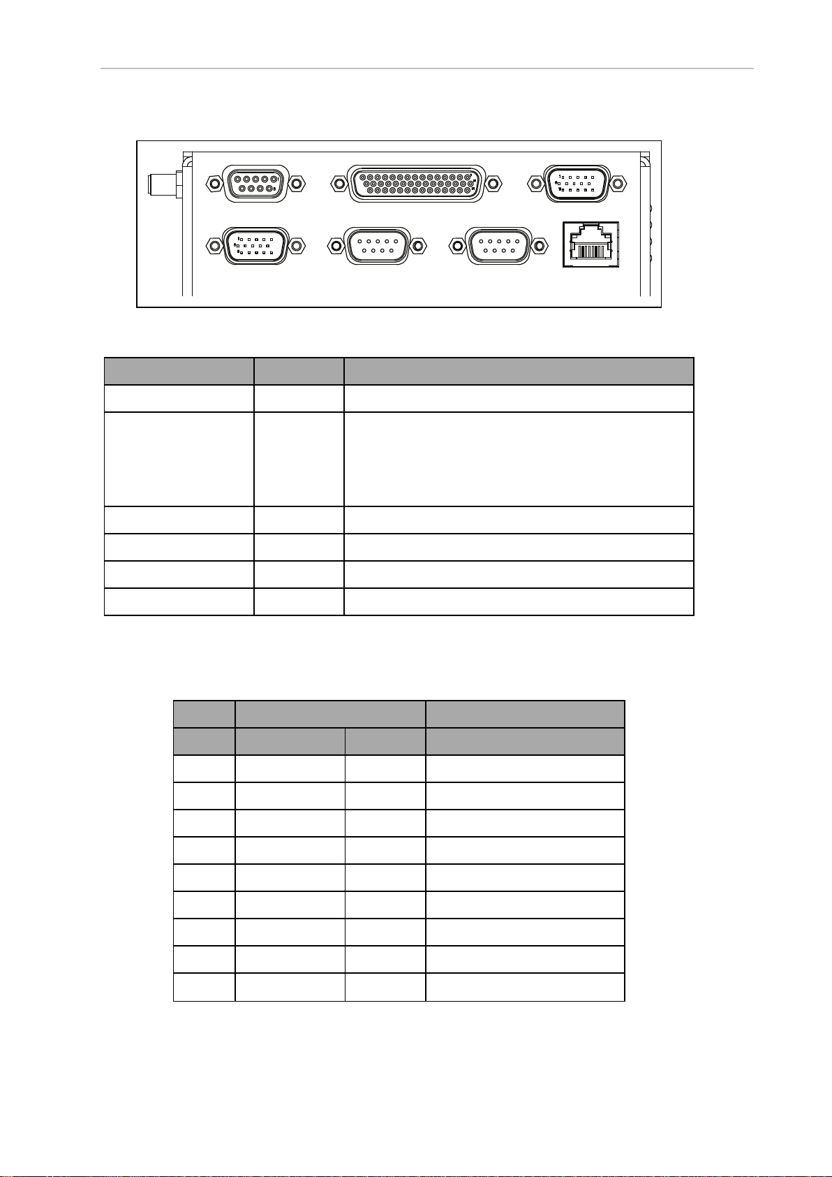
6.2 Payload Bay Connections - LD-250 Core
CAN Bus B Digital I/O
Analog I/O
User LANRS232-1RS232-2A
ux Sensors
LD-250 Core Front, Upper
Figure 6-1 Front Upper LD-250 Core
Connection Type Description
CAN Bus B DB9F Unused
Digital I/O
a
HDB44F 16 digital inputs, in 4 banks of 4. Each bank can be
wired as active high or active low depending on the connection of the BANK# terminal.
VINrange for each input is 0 to 30 V. The input is ON
when VIN> 4 V, OFF when VIN< 1.3 V.
Analog I/O General use.
User LAN RJ45 General Ethernet, Auto-MDIX, shielded
RS-232 x 2 DB9M Port 1 and Port 2, general use
Aux Sensors HDB15M Low front and optional side lasers
Digital I/O
The LD-250 Core's Digital I/O HDB44F connector provides the user with digital inputs and outputs for payload customization.
Designation
Pin No. Hardware Software Notes
1 INPUT_1.1 Input_1.1 0 – 30 V Range, Rin= ~3.9 kΩ
2 INPUT_1.2 Input_1.2 0 – 30 V Range, Rin= ~3.9 kΩ
3 INPUT_1.3 Input_1.3 0 – 30 V Range, Rin= ~3.9 kΩ
4 INPUT_1.4 Input_1.4 0 – 30 V Range, Rin= ~3.9 kΩ
5 BANK1 Common for INPUT_1.X
6 INPUT_2.1 Input_2.1 0 – 30 V Range, Rin= ~3.9 kΩ
7 INPUT_2.2 Input_2.2 0 – 30 V Range, Rin= ~3.9 kΩ
8 INPUT_2.3 Input_2.3 0 – 30 V Range, Rin= ~3.9 kΩ
9 INPUT_2.4 Input_2.4 0 – 30 V Range, Rin= ~3.9 kΩ
94 LD-250 Platform User's Manual 20472-000 Rev D
Page 95

Chapter 6: Connectivity
Designation
Pin No. Hardware Software Notes
10 BANK2 Common for INPUT_2.X
11 INPUT_3.1 Input_3.1 0 – 30 V Range, Rin= ~3.9 kΩ
12 INPUT_3.2 Input_3.2 0 – 30 V Range, Rin= ~3.9 kΩ
13 INPUT_3.3 Input_3.3 0 – 30 V Range, Rin= ~3.9 kΩ
14 INPUT_3.4 Input_3.4 0 – 30 V Range, Rin= ~3.9 kΩ
15 BANK3 Common for INPUT_3.X
16 INPUT_4.1 Input_4.1 0 – 30 V Range, Rin= ~3.9 kΩ
17 INPUT_4.2 Input_4.2 0 – 30 V Range, Rin= ~3.9 kΩ
18 INPUT_4.3 Input_4.3 0 – 30 V Range, Rin= ~3.9 kΩ
19 INPUT_4.4 Input_4.4 0 – 30 V Range, Rin= ~3.9 kΩ
20 BANK4 Common for INPUT_4.X
21 OUTPUT_1 Output_1
22 OUTPUT_2 Output_2
23 OUTPUT_3 Output_3
24 OUTPUT_4 Output_4
25 OUTPUT_5 Output_5
26 OUTPUT_6 Output_6
27 OUTPUT_7 Output_7
28 OUTPUT_8 Output_8
29 OUTPUT_9 Output_9
30 OUTPUT_10 Output_10
31 OUTPUT_11 Output_11
32 OUTPUT_12 Output_12
33 OUTPUT_13 Output_13
34 OUTPUT_14 Output_14
35 OUTPUT_15 Output_15
36 OUTPUT_16 Output_16
37 VBAT_IO_OUT4 VBAT @ 0.5 A Max
(shared with light pole)
38 VBAT_IO_OUT3 VBAT @ 0.5 A Max
39 VBAT_IO_OUT2 VBAT @ 0.5 A Max
20472-000 Rev D LD-250 Platform User's Manual 95
Page 96

6.2 Payload Bay Connections - LD-250 Core
Designation
Pin No. Hardware Software Notes
40 VBAT_IO_OUT1 VBAT @ 0.5 A Max
41 - 44 GND
96 LD-250 Platform User's Manual 20472-000 Rev D
Page 97

Digital Input Specifications
The following tables describe specifications for the LD-250 Core's digital inputs.
Table 6-1 Digital Input Specifications
Parameter Value
Operational voltage range 0 to 30 VDC
OFF state voltage range 0 to 1.3 VDC
ON state voltage range 4 to 30 VDC
Operational current range 0 to 7.5 mA
OFF state current range 0 to 0.5 mA
ON state current range 1.0 to 7.5 mA
Impedance (Vin/Iin) 3.9 kΩ minimum
Current at Vin= +24 VDC Iin≤ 6 mA
Chapter 6: Connectivity
NOTE: The input current specifications are provided for reference. Voltage
sources are typically used to drive the inputs.
Figure 6-2 Typical Digital Input Wiring Example
20472-000 Rev D LD-250 Platform User's Manual 97
Page 98
6.2 Payload Bay Connections - LD-250 Core
Callout Side 1 (Left)
I/O Connector
Callout Side 2 (Right)
User-Supplied Equipment
A Equivalent Circuit F Terminal Block
B Input Bank 1 G Typical User Input Signal
C Input Bank 2 H Part Present Sensor
D Input Bank 3 I Bank 1 configured for sinking (NPN) inputs
E Input Bank 4 J Bank 4 configured for sourcing (PNP) inputs
NOTE: You can use all input signals for either sinking or sourcing configurations.
Table 6-2 Digital Output Specifications
Parameter Value
Power supply voltage range 5 - 30 VDC
Operational current range, per channel I
ON state resistance (I
= 0.5 A) Ron≤ 0.14 Ω @ 85°C
out
Output leakage current I
DC short circuit current limit 0.7 A ≤ I
≤ 500 mA
out
≤ 5 μA
out
LIM
≤ 1.7 A
Figure 6-3 Typical Digital Output Wiring Example
98 LD-250 Platform User's Manual 20472-000 Rev D
Page 99

Chapter 6: Connectivity
Callout Description Callout Description
A Standard Equipment E Load
B User-Supplied Equipment F Outputs 1-16
C Wiring Terminal Block G Equivalent Circuit
D Typical User Loads
Analog I/O
The LD-250 Core's Analog I/O HDB15M connector is reserved for internal use only. Contact
your local OMRON Support before attempting to use these circuits.
Aux Sensors
The LD-250 Core's Aux Sensors HDB15M connector provides circuits used by the Low Front
Laser and optional Side Lasers (tilted lasers).
Designation
Pin No. Hardware Software Notes
1 RS232_VERT1_TXD /dev/ttyUSB5 (side lasers)
2 RS232_VERT2_TXD /dev/ttyUSB6 (side lasers)
3 RS232_FOOT_TXD /dev/ttyUSB7 (low front laser)
4 5V_SW1 USB_1_and_2_Power 5 V @ 1 A (shared with USB port 1)
5, 10 SW_20V_VERT Vertical_Laser_Power 20 V @ 300 mA (side lasers)
6, 7, 8 GND
9 5V_SW2 USB_1_and_2_Power 5 V @ 1 A (shared with USB port 2)
11 RS232_VERT1_RXD /dev/ttyUSB5 (side lasers)
12 RS232_VERT2_RXD /dev/ttyUSB6 (side lasers)
13 RS232_FOOT_RXD /dev/ttyUSB7 (low front laser)
14 5V_SW3 USB_3_Power 5 V @ 1 A (shared with USB port 3)
15 SW_20V_FOOT Foot_Laser_Power 20 V @ 150 mA (low front laser)
20472-000 Rev D LD-250 Platform User's Manual 99
Page 100
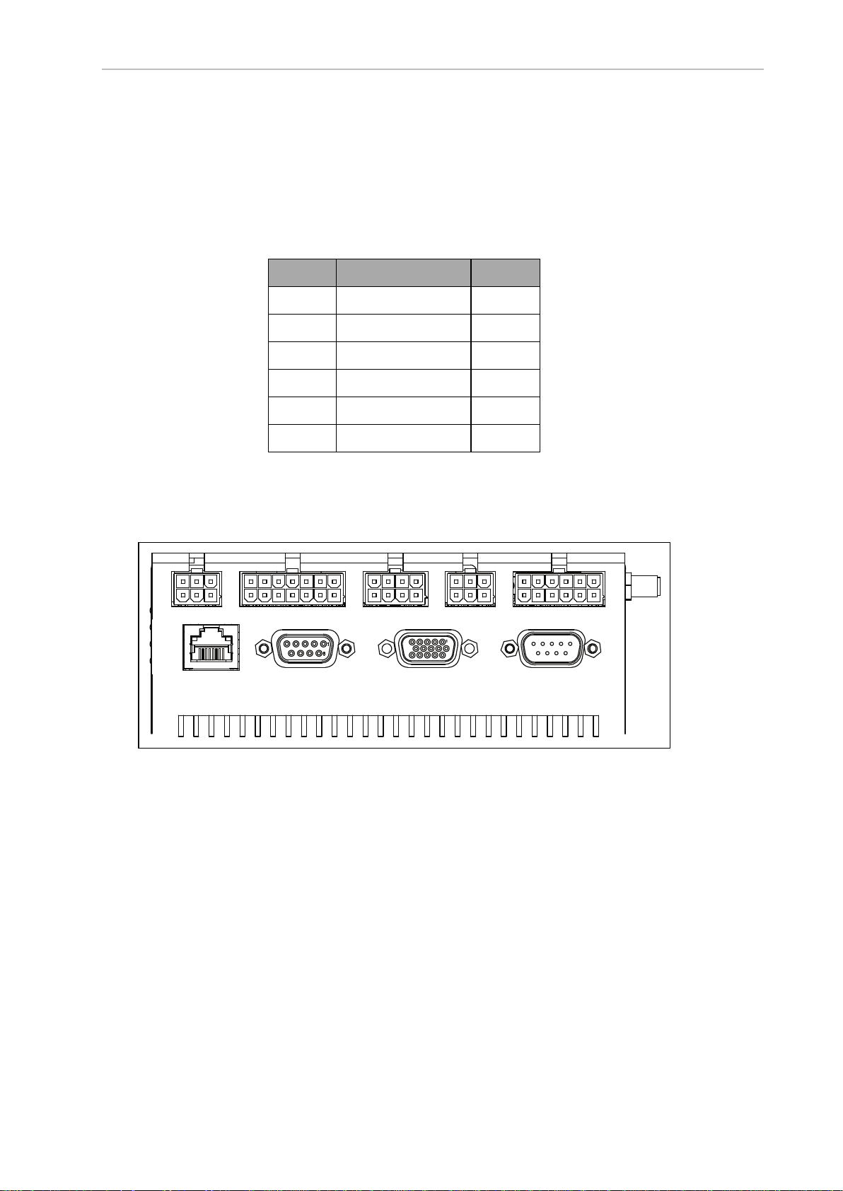
6.2 Payload Bay Connections - LD-250 Core
Light Pole User Interface User Bumpers Aux Power User Power
Maint LAN Joystick HMI Panel Sonar 2
RS232 1 and 2
The LD-250 Core's RS232 1 and 2 DB9M connector provides two ports for use with peripheral
devices such as the HAPS sensors (See: High-Accuracy Positioning System (HAPS) on page 188.)
If not used for other devices, you can also use the ports for port forwarding information from
other RS232 devices. See the SetNetGo chapter in the Fleet Operations Workspace Core User's
Manual (Cat. No. I635).
Pin No. Designation Notes
1, 4, 6, 9 No Connection
2 RS232_USR#_RXD #=1 or 2
3 RS232_USR#_TXD #=1 or 2
5 GND
7 RS232_USR#_RTS #=1 or 2
8 RS232_USR#_CTS #=1 or 2
LD-250 Core Rear Upper Connectors
Figure 6-4 shows the connectors on the LD-250 Core's upper rear interface panel. Some if these
connectors are available for customer use.
Figure 6-4 LD-250 Core Rear Upper Interface Panel
Table 6-3 describes the connector type and typical use of the connector.
100 LD-250 Platform User's Manual 20472-000 Rev D
 Loading...