

Page 1
OMRON Corporation 2018 All Rights Reserved.
OMRON Corporation
2838272-8 A
July, 2017
Ự傼Ṭ
Ự傼ઈ˖
/1
./
⭫Ⓠם 䍕㦭ם
ᯣ䐥ಞ 䍕㦭
&7
c
2013年7月
技术咨询
欧姆龙自动化(中国)有限公司
地址:中国上海市浦东新区银城中路200号
中银大厦2211室
电话:(86)21-5037-2222
技术咨询热线:400-820-4535
网址:http://www.fa.omron.com.cn
model KM-NCT-E@@@A
Split Type Current Transformer
EN
INSTRUCTION MANUAL
Thank you for purchasing the KM- NCT-E@@@A.
Always need the following points when using the KM-NCT-E@@@A.
• This product is designed for use by qualified personnel with a knowledge of electrical systems.
• Before using the product, thoroughly read and understand this manual to ensure correct use.
• Keep this manual in a safe locat ion so that it is available for reference whenever requi red.
Key to Warning Symbols
CAUTION
Alert Statements
Property damage may occur due to fi re.
Tighten the terminal screws to the specified torques.
After tightening the screw, check that the screw is not loose.
M3 screw : 0.3 N·m
Minor or moderate injury or property damage may occur due to explosion.
Do not use in locations exposed to flammable or explosive gases.
Electric shock may occasionall y occur.
During mounting, always work with the power supply turned OFF both the main power
supply and breaker.
Electric shock may occasionall y occur.
Be sure to mount to coated wire with at least the basic insulation.
Electric shock may occasionall y occur.
Do not touch any of the terminals whi le the power is being supplied.
Minor electric shock, fire, or malfunction may occasionally occur.
Never disassemble, modify, or re pair the product.
PRECAUTIONS ON SAFETY
Indicates a potentially hazardous situation which, if not avoided, will
result in minor or moderate injury, or there may be property damage.
CAUTION
Observe the following prec autions to ensure safe use of KM-NCT-E@@@A (hereinafter called KM-NCT-E).
• Do not use or store the product in any of the following locations.
Locations subject to shock or vibration
Unstable locations wher e the user might fall/tumble down
Locations subject to temperatures or humidity outside rated ranges
Locations subject to condensation as the result of severe changes in temperat ure
Outside or otherwise ex posed to direct sunlight and weather
Locations subjec t to static electricity or other for ms of noise
Locations exposed to electromagnetic fields
Locations subject to exposure to water or oil.
Locations subject to exposure to salt water spray.
Locations subject to corrosive gases (in particular, sulfide gas and ammonia gas).
Locations subjec t to dust (including iron dust).
Locations subject to exposure to solvents
• Be sure to wire properly with the terminals with correct symbols.
• For wiring to the output terminal, use a Y-shape terminal compatible with AWG18-14 electric wire (with
a cross-section of 0.75-2.0mm
• The recommended tightening torque of the M3 screw is 0.3N·m.
• Do not pull the wired cables.
• Before using or maintaining the product, thoroughly read and understand this manual.
• When mounting the KM-NCT-E to the measurement wire, push the fitting claw until it clicks.
• Do not install the produc t close to heat-producing devices (those using co il elements, for instance).
• Do not exceed the rated pr imary side current value.
• KM-NCT-E is a dedicated CT for KM -N2-FLK and KM-N3-FLK. Do not use it for other power monitors.
• Always check the wir ing and confirm that it is correct before t urning ON the power supply. Incorrect or
improper wiring may result in electrical shock, injury, accidents, failure, or malfunction.
• The surface temperature of the CT may become high due to the heat generated by the primary power
cable. Be sure to check that the sur face temperature of the CT went dow n before touching the CT
immediately after turning ON the power supply.
2
) and M3 screw.
PRECAUTIONS FOR CORRECT USE
• This product is not categorized as "a specified measuring instrument" officially approved by an
organization specified in relevant measurement acts. It cannot be used to ce rtify power usage.
• When cleaning the unit, ma ke sure the power is off and wipe the surfac e of the unit with a soft dry cloth.
Do not use chemicals including solvents such as thinners, benzine, or alcohol.
• Dispose of this product appropriately as industrial refuse in accordance with local and national regulations.
• This product is i ntended for use in industrial environments. Do not use it in residential environment.
PRECAUTIONS FOR SAFE USE
■ Specifications
Model KM-NCT-E100A KM-NCT-E250A KM-NCT-E500A
Rated primary current: In 100 A 250 A 500 A
Rated secondary current: Is 1 A
Rated frequency 50/60Hz
Overcurrent withstand
capability (continuous)
Overcurrent withstand
capability (1 sec)
Output characteristics ±3%FS ±1%FS
Phase error ±180 minutes (1.0 In)
Rated load 1 VA
Insulation resistance 100M min. (at DC500V mega) between core and all output terminals
Dielectric strength voltage AC2300V, 1 minute between core an d all output terminals
Weight Approx. 170g Approx. 175g Approx. 290g
Maximum wire diameter 24 dia. 24 dia. 36 dia.
Output overvoltage prote ction Built-in clamp element
Operating temperature and
humidity range
Storage temperature and
humidity range
Applicable standards * EN61010-1, EN61010-2-030, EN61326- 1
Installation environment Overvoltage c ategory and measurement category: II, Pollution level: 2
* The KM-NCT-E conforms to the standards shown above ONLY when it is used with a power monitor
KM-N2-FLK or KM-N3-FLK to which it is attached. Use of the KM-NCT-E without a power monitor do es
not conform to these standards.
* UL standards are not supported.
■ Wiring to KM-NCT-E@@@A
• For wiring of the output termi nal of CT, use AWG18-14 electric wir e (with a cross-section of 0.75-
2
2.0mm
) and Y-shape terminal compatible with the M3 screw.
• The recommended torque for screwing the M3 screws onto the output terminal is 0.3 N·m. Ma ke sure
the Y terminal is pushed all the way in and tightened firmly. After fixing the wiring, confirm that the wire
is fixed securely.
• The guideline of the maximum wirin g length between KM-N2-FLK/KM-N3- FLK and KM-NCT-E is as
follows. The longer the wire length, the larger the measurement error using the KM-NCT-E becomes.
• The limit of the wiring length c an also be calculated by the following formula. Calculate the wiring length
limit according to the conductor resistivity of the wiring and keep the wiring length below the limit .
• The limits of the wiring length shown below are for reference only. They do not guarantee pr oper use.
Wiring diameter
2
0.75 mm
(AWG18 equivalent)
2
2.0 mm
(AWG14 equivalent)
1.2 In
4 In
±240 minutes (0.2 In)
-20 to 55°C, relative humidity: 85% max. with no condensation
-30 to 90°C, relative humidity: 85% max. with no condensation
Guideline for wiring
length limit
15m
43m
±60 minutes (1.0 In)
±90 minutes (0.2 In)
Wiring extension limit va lue (one-way) (m) =
0.475/conductor resistivity (/m)
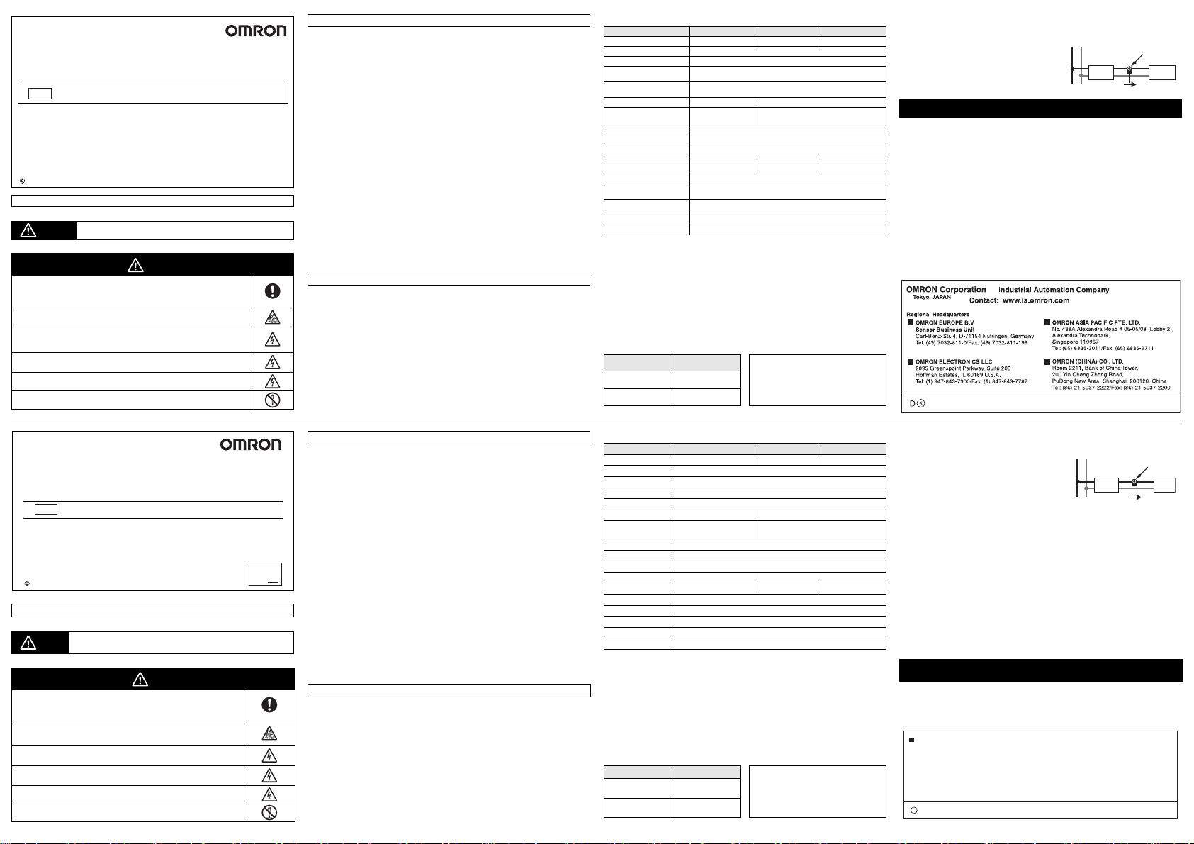
■ Mounting to measurement wire
For safety purposes, tu rn off the mains power and the breaker to ensure th ere is no power supply whi le
you are working.
• The current transformer has polarity. Confirm the
directions from the power side (K) to the load side (L)
before connecting it. You will be unable to measure
correctly if you make a mistake wi th the directions.
• Be sure to mount the KM-NCT-E to a coated wire.
• Do not turn on the power with th e secondary side open.
* For details on wiring to the power mon itor, refer to the
corresponding manual.
LN
Breaker Load
KL
Power side Load side
CT
General agreement regarding use
Omron Products are designed and manufactured as general-purpose products for use in general industrial
products. They are not intended to be used in the applications described below, therefore if you use
Omron products in these applica tions, Omron provides no warranty for Omron products. Ho wever, this
excepts cases where Omron has specified that it agrees to provide a warranty, even when used in the
following applications.
(a) Applic ations with stringent safety requirements (For e xample, nuclear power control equipment,
combustion equipment, aero space equipment, railway equipment, elevator and l ift equipment,
amusement equipment, medic al equipment, safety equipment, and other applicat ions that could
cause physical injury or result in the loss of life.)
(b) Applic ations that require high reliability (For exampl e, supply systems for gas, water and electricity,
etc., 24 hour continuous operating systems, financial settlement systems and other applications that
handle rights and property.)
(c) A pplications under severe conditions or in severe environments (For example, outdoor equipment,
equipment exposed to chemical contamination, equipment exposed to electromagnetic interference
and equipment exposed to vibration and shocks.)
(d) Applic ations under conditions or environments not descr ibed in catalogs or other publications.
In addition to the appl ications listed in (a) to (d), the produc ts in this publication are not intended for use in
automobiles (including for two-wheeled vehicles, and this description applies hereafter). Do not use for
applications involving fi tting to automobiles. Consult Omron staff for informa tion about products suitable
for use in automobiles.
The above are some of the conditi ons for use of this product. Please carefully read th e warranties and
limitations of liabiliti es printed in our most up-to-date catalogs and manuals, including accompanying
catalogs and datasheets.
KM-NCT-E@@@A
独立型变流器
CHN
使用说明书
本次承蒙惠购本产品,谨致谢意。
使用时,请务必遵守以下内容。
• 请由具备电气知识的专业人士进行操作。
• 请在熟读本使用说明书,并充分掌握其内容的前提下,正确使用本产品。
• 请妥善保管本使用说明书,以便随时查阅。
欧姆龙公司
OMRON Corporation 2018 All Rights Reserved.
安全注意事项
警告标示的含义
警告标示
极少数情况下可能会引发起火,导致财物损失。
请务必按照规定的扭矩拧紧端子螺丝。
请确保拧紧螺丝。
M3 螺丝: 0.3 N·m
极少数情况下可能会引发爆炸,可能会导致中度、轻度的人身伤害及财物损失
等后果。
请不要在含有易燃、易爆气体的场所使用本产品。
偶尔会有触电的危险。
安装时请务必切断主电源和断路器后在非通电状态下进行操作。
偶尔会有触电的危险。
请务必安装于达到基本绝缘标准以上的绝缘线上。
极少数情况下存在触电风险。
通电状态下,请勿触摸端子。
极少数情况下可能会导致触电、轻伤、起火、设备故障等后果。
请勿拆卸、修理、改造本产品。
若不采取正确的使用方法,可能会导致轻伤、中度伤害及财物损失等
注意
后果。
注意
为了确保型号 KM-NCT-E □□□ A(以下简称型号 KM-NCT-E)的安全使用,请务必遵守以下事项。
• 请勿在下列环境中进行本产品的存放、安装、使用。
- 受震动、冲击影响大的环境
- 不稳定且可能掉落或倒塌的场所
- 超出规格规定范围的温湿度环境
- 温湿度变化剧烈,可能结露、结冰的环境
- 户外或是会暴露在阳光直射、风吹雨淋下的环境
- 受静电、噪音影响的环境
- 受电场、磁场影响的环境
- 易浸水、沾油的环境
- 有盐水飞溅的环境
- 有腐蚀性气体 (特别是硫化气体、氨类气体)的环境
- 粉尘、铁粉等多的环境
- 有溶解性液体的环境
• 请确认端子符号后正确排线。请勿在不使用的端子上连接任何电缆。
• 输出端子的配线请使用AWG18 ~ 14 (断面积 0.75~ 2.0mm
端子。
• 输出端子的M3 螺钉推荐紧固扭矩为 0.3N·m。
• 请勿强力拉伸配线电缆。
• 请在充分理解本使用说明书的基础上,进行使用及维保。
• 将型号KM-NCT-E 安装于计测电线时,请将扣合卡爪推入至听到 “ 咔嚓 ”声为止。
• 请勿将本产品安装在靠近发热设备 (含有线圈、绕组的设备等)的位置。
• 使用时请勿超出额定一次侧电流值范围。
• 型号KM-NCT-E 是型号 KM-N2-FLK、型号 KM-N3-FLK 的专用 CT。请勿用于其他电能监测仪。
• 使用设备前请务必确认接线无误后再接通电源。否则可能会因接线不良而导致触电、受伤、事
故、故障、错误运行的危险。
• 一次侧电线的发热可能会导致CT 表面温度升高。
通电后,请务必在确认 CT 表面温度已下降后再触碰。
2
)的电线以及适用于 M3 螺钉的 Y 型
使用注意事项
• 本产品并非计量法所规定的指定机构认证合格的特定计量设备。不推荐使用本产品进行电能用量
证明。
• 清洁本产品时,请务必在未通电的状态下,用柔软的干布擦拭产品表面。此外,请勿使用包含稀
释剂、轻汽油、酒精等溶剂成分的药品等。
• 清洁时请勿使用稀释剂类物质。请使用市面销售的酒精进行清洁。
• 本产品为工业环境产品。请勿在住宅环境中使用。
安全要点
■规格
型号 型号 KM-NCT-E100A 型号 KM-NCT-E250A 型号 KM-NCT-E500A
额定一次电流:In 100A 250A 500A
额定二次电流:Is 1A
额定频率 50/60H z
过电流耐量 ( 连续 ) 1.2 In
过电流耐量 (1 秒 ) 4 In
输出特性 ±3%FS ±1%FS
相位差 ±180分 钟 (1.0 I n)
额定负荷 1VA
绝缘电阻 100MΩ 异常 (使用 DC500V 兆欧表) 磁芯与所有输出端子之间
耐电压 AC2300V 1 分钟 磁芯与所有输出端子之间
重量 约 170g 约 175g 约 290g
电线最大直径 φ24 φ24 φ36
输出过电压保护 使用内置固定元件
使用温湿度范围 -20 ℃~ +55 ℃ 相对湿度 85%RH 以下 ( 但不得结露)
保存温湿度范围 -30 ℃~ +90 ℃ 相对湿度 85%RH 以下 ( 但不得结露)
适用规格 * EN61010-1、EN61010-2-030、EN6132 6-1
设置环境 过电压分类、测定分类:II、污染度:2
* 仅限安装于型号KM-N2-FLK、型号KM-N3-FLK 上使用时,所装电量监测仪与本产品方为适用规格。
本产品单体非上述适用规格。
* 不支持UL 规格。
■ 型号 KM-NC T-E □□□ A 上的 配线
• CT 输出端子的配线请使用 AWG18 ~ 14 (断面积 0.75 ~ 2.0mm2)的电线以及适用于 M3 螺钉的 Y
型端子。
• 输出端子的 M3 螺钉推荐扭矩为 0.3N·m。请将 Y 型端子插入最深处,然后进行紧固。配线固定
后,请确认是否固定牢固。
• 型号KM-N2-FLK 或 型号KM-N3-FLK 与型号 KM-NCT-E 之间的配线长度限值参考值如下所示。如果
配线过长,则会导致型号 KM-NCT-E 上的计测误差增大。
• 配线长度限值还可通过以下公式计算。请在基于所用排线的导电体电阻率算出排线长度限值后,
采用排线长度限值以下的排线长度。
• 下表及通过下述公式算出的配线长度限值均为参考值,并不保证能否正常使用。
配線径 配线长度参考限值
2
0.75mm
(相当于 AWG18)
2
2.0mm
(相当于 AWG14)
±240 分 钟 (0.2 In)
15m
43m
±60 分钟 (1.0 In)
±90 分钟 (0.2 In)
配线延长限值 (单程)(m)=
0.475/ 导电体电阻率 (Ω/m)
■ 计测电线上的安装
为了确保安全,请务必切断主电源及断路器电源,在无通电状态下执行作业。
• 变流器上带有极性。请在确认电源侧 (K)、负荷侧 (L)
的方向后再进行连接。方向一旦接错则无法正确测量。
• 请务必安装于绝缘线上。
• 请勿在二次侧开放状态下接通电源。
* 电能监测仪上的配线方法请分别参阅各使用说明书。
使用时的注意事项
在客户的应用中,欧姆龙不负责产品与任何客户端产品所涉及的规格、规范和标准保持一致性。请务
必考虑本产品对于所应用的系统、机器和设备间的适用性。使用时请注意并遵守本产品的禁止事项。
在没有确认整个系统设计时所考虑到的风险,以及没有确认在设备和系统中该欧姆龙产品的额定使
用条件和正确安装条件的情况下,禁止将本产品应用于对人身及财产存在严重危险的场合。详见产
品规格书中保证及免责事项内容。
Page 2
JPN
OMRON Corporation 2018 All Rights Reserved.
LN
KL
電源側 負荷側
ブレーカ 負 荷
CT
④
①
③
②
⑤
形KM-NCT-E □□□ A
分割型変流器
取扱説明書
このたびは、本製品をお買い上げいただきまして、まことにありがとうございます。
ご使用に際しては、次の内容をお守りください。
• 電気の知識を有する専門家がお取り扱いください。
• この取扱説明書をよくお読みになり、十分にご理解の上、正しくご使用ください。
• この取扱説明書はいつでも参照できるように大切に保管してください。
安全上のご注意
警告表示の意味
警告表示
稀に発火による物的損害が起こる恐れがあります。
端子ねじは規定トルクにて確実に締め付けてください。
締め付け後、ねじの緩みがないことを確認してください。
M3ねじ: 0.3N・m
稀に爆発により中程度・軽度の人身傷害や物的損害が起こる恐れがあります。
引火性、爆発性ガスのあるところでは使用しないでください。
稀に感電の恐れがあります。
取付時は必ず主電源とブレーカを OFF して無 通電で作業してください。
稀に感電の恐れがあります。
必ず基礎絶縁以上の被覆電線に取り付けてください。
稀に感電の恐れがあります。
通電中は端子に触れないでください。
稀に感電や軽度のけが、発火、機器の故障が起こる恐れがあります。
分解したり、修理、改造をしないでください。
正しい取り扱いをしなければ、この危険のために、時に軽傷・中程度の 傷害を
注意
負ったり、あるいは物的損害を受ける恐れがあります。
注意
安全上の要点
形 KM-NCT-E □□□ A(以下、形 KM-NCT-E)を安全に使用するために、以下のことを守ってください。
• 下記の環境では保管・設置・使用しないでください。
− 振動、衝撃の影響が大きいところ
− 不安定で落下や転倒の可能性があるところ
− 仕様範囲外の温湿度のところ
− 温湿度変化が激しく、結露・氷結の恐れがあるところ
− 屋外または直接日光、風雨にさらされるところ
− 静電気やノイズの影響を受けるところ
− 電界及び磁界の影響をうけるところ
− 冠水、被油のあるところ
− 塩水飛沫のあるところ
− 腐食性ガス(特に硫化ガス、アンモニアガス)のあるところ
− 粉塵、鉄粉などの多いところ
− 溶解性液体のあるところ
• 端子記号を確認し、正しく配線してください。
• 出力端子への配線は、AWG18〜 14(断面積0.75 〜 2.0mm
端子を使用してください。
• 出力端子の M3 ねじの推奨締め付けトルクは 0.3N・m です。
• 配線したケーブルを引っ張らないでください。
• 取扱いおよび保守は、取扱説明書をよく理解してから行ってください。
• 形 KM-NCT-E を計測電線に取り付ける際は、勘合ツメをカチッと音がするまで押し込んでください。
• 発熱機器(コイル、巻線を有する機器等)と近接して取り付けないでください。
• 定格一次側電流値を超えないように使用してください。
• 形 KM-NCT-E は、形 KM-N2-FLK、形 KM-N3-FLK 専用の CT です。他の電力量モニタには使用し
ないでください。
• 機器を使用する前には必ず配線の確認を行った上で、電源を投入してください。配線の不良などにより
感電、けが、事故、故障、誤動作の恐れがあります。
• 一次側電線の発熱により、CT の表面温度が高くなることがあります。
通電直後に触れる場合は CT 表面の温度が下がっていることを確認してください。
2
)の電線とM3 ねじに適合する、Y
使用上の注意
• 本製品は計量法に定める指定機関が行う検定に合格した特定計量器ではあ りません。電力量の証明に
は使用できません。
• 製品の汚れを落とす場合は必ず無通電の状態で、柔らかい布で製品表面を乾拭きしてください。なお、
シンナー、ベンジン、アルコールなどの溶剤を含む薬品等を使用しないでください。
• 本製品の廃棄については、各自治体の指示に従い、産業廃棄物として適切に処理してください。
• 本製品は工業環境製品です。住宅環境で使用しないで下さい。
■仕様
形式 形 KM-NCT-E100A 形 KM-NCT-E250A 形 KM-NCT-E500A
定格一次電流:In 100A 250A 500A
定格二次電流:Is 1A
定格周波数 50/60Hz
過電流耐量(連続) 1.2In
過電流耐量(1 秒) 4In
出力特性 ±3%FS ±1%FS
位相差 ±180 分(1.0In)
定格負担 1VA
絶縁抵抗 100MΩ 以上(DC500V メガにて)コアと出力端子一括間
耐電圧
質量 約 170g 約 175g 約290g
最大電線径 φ24 φ24 φ36
出力過電圧保護 内蔵クランプ素子による
使用温湿度範囲 − 20 ℃〜+ 55 ℃ 相対湿度 85%RH 以下(ただし結露しないこと)
保存温湿度範囲 − 30 ℃〜+ 90 ℃ 相対湿度 85%RH 以下(ただし結露しないこと)
適合規格 ※ EN61010-1、EN61010-2-030、EN61326-1
設置環境 過電圧カテゴリ、測定カテゴリ:II、汚染度:2
※ 形 KM-N2-FLK、形 KM-N3-FLK に取り付けて使用したときのみ、取り付けた電力量モニタと本製
品で合わせて規格への適合となります。本製品単体では上記の規格適合となりません。
※ UL 規格は非対応です。
■ 形 KM-NCT-E □□□ A への配線
• 出力端子への配線は、AWG18 〜 14(断面積0.75〜2.0mm2)の電線と M3ねじに適合する、
Y 端子を使用してください。
• 出力端子の M3 ねじの推奨締め付けトルクは 0.3N・m です。Y 端子を奥までしっかりと差し込んで、
確実に締め付けてください。配線固定後に確実に固定されていることを確認してください。
• 形 KM-N2-FLK 又は形 KM-N3-FLK と、形 KM-NCT-E 間の配線長の限度目安は以下のとおりです。
配線長が長いと形 KM-NCT-E での計測誤差が大きくなります。
• 配線長限度は以下の式で算出することもできます。使用される配線の導体抵 抗率より配線長限度を算
出のうえ、配線長限度以下の配線長でご使用ください。
• 下表および下記式による配線長限度はあくまで目安です。使用を保証するものではありません。
配線径 配線長限度目安
2
0.75mm
(AWG18 相当)
2
2.0mm
(AWG14 相当)
±240 分(0.2In)
AC2300V 1 分 コ アと出力端子一括間
15m
43m
±60 分(1.0In)
±90 分(0.2In)
配線延長限度値(片道)(m)=
0.475/ 導体抵抗率(Ω/m)
■ 計測電線への取り付け
安全のため、必ず主電源とブレーカを OFF して無通電で作業してください。
• 変流器には極性があります。電源側(K)、負荷側(L)の
方向を確認してから接続してください。
方向を間違えると正しく計測できません。
• 必ず被覆電線に取り付けてください。
• 二次側開放状態で通電しないでください。
※ 電力量モニタへの配線方法は、それぞれの取扱説明書を
参照してください。
ご承諾事項
当社商品は、一般工業製品向けの汎用品として設計製造されています。従いまして、次に掲げる用途での
使用を意図しておらず、お客様が当社商品をこれらの用途に使用される際には、当社は当社商品に対して
一切保証をいたしません。ただし、次に掲げる用途であっても当社の意図した特別な商品用途の場合や特
別の合意がある場合は除きます。
(a)高い安 全性が必要とされる用途(例:原子力制御設備、燃焼設備、航空・宇宙設備、鉄道設備、昇降
設備、娯楽設備、医用機器、安全装置、その他生命・身体に危険が及びうる用途)
(b)高い信頼性が必要な用途(例:ガス・水道・電気等の供給システム、24 時間連続運転システム、決
済システムほか権利・財産を取扱う用途など)
(c)厳しい 条件または環境での用途(例:屋外に設置する設備、化学的汚染を被る設備、電磁的妨害を被
る設備、振動・衝撃を受ける設備など)
(d)カタログ等に記載のない条件や環境での用途
*(a)から(d)に記載されている他、本カタログ等記載の商品は自動車(二輪車含む。以下同じ)向けで
はありません。自動車に搭載する用途には利用しないで下さい。自動車搭載用商品については当社営
業担当者にご相談ください。
* 上記は適合用途の条件の一部です。当社のベスト、総合カタログ、データシート等最新版のカタログ、
マニュアルに記載の保証・免責事項の内容をよく読んでご使用ください。
v
2017年5月A
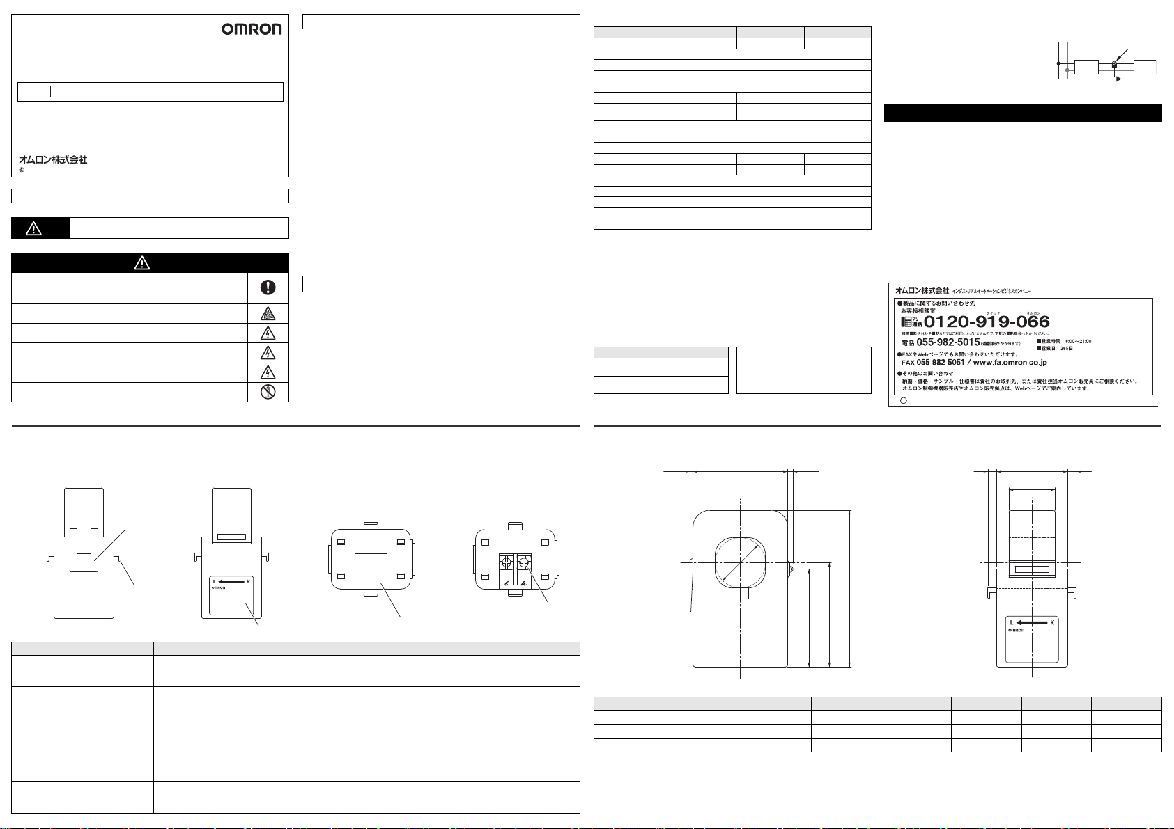
Names of the parts and their functions / 各部分名称及功能 / 各部の名称とはたらき Dimensions (Unit: mm) / 外形尺寸 ( 單位 :mm) / 外形寸法(単位:mm)
Front/
正面 /
正面
Name / 名称 / 名称 Function / 功能 / 機能
①Label/
①标签 /
①ラベル
②Output terminal block/
②输出端子台 /
②出力端子台
③Terminal cover/
③端子外盖 /
③端子カバー
④Fitting claw/
④扣合卡爪/
④勘合ツメ
⑤Fixing claw/
⑤固定卡爪 /
⑤固定ツメ
Polarity of the primary side wiring, and models are written on this label
记载了一次侧配线的极性、型号等的标签
一次側配線の極性、形式等を記載したラベル
Secondary side current is output to this terminal block
输出二次侧电流的端子台
二次側電流を出力する端子台
Protective cover of the output terminal block
输出端子台的保护盖盖
出力端子台の保護カバー
Claw that clamps the wire an d fits the top and bottom of the transformer
夹紧电线、使变流器上部与下部相互扣合所需的卡爪
電線をクランプし変流器の上部と下部を勘合させるためのツメ
Used to reinforce the retention of the unit and insulation lock
使用束带等对与电线的保持进行加固所需的卡爪
インシュロック等で電線との保持を補強するためのツメ
Back/
背面 /
背面
Bottom/
底面 /
底面
Bottom (terminal cover removed)/
底面 (拆除端子外盖后的状态)/
底面(端子カバーを外した状態)
W1
(2.5)(1.5)
φd
H3
H2
H1
Dimensions / 尺寸 / 寸法 φd W1 W2 H1 H2 H3
KM-NCT-E100A 24 45 34 46.5 49.5 74.5
KM-NCT-E250A 24 45 34 46.5 49.5 74.5
KM-NCT-E500A 36 57 40.5 56.5 61 91
(4) (4)W2
22
 Loading...