

Page 1

Power Monitor
model KM-N2-FLK
Users Manual
1.Overview of the unit
2.Installation and wiring
3.Basic use
Thank you for purchasing this power monitor, model KM-N2-FLK
(referred to as model KM-N2 in this manual).
This Users Manual describes the functions, performance, and
application methods needed for optimum use of the unit.
Please observe the following when using this unit.
• This product is designed for use by qualified personnel with a
knowledge of electrical systems.
• Before using the product, thoroughly read and understand this Users
Manual to ensure correct use.
• Keep this Users Manual in a safe location so that it is available for
reference whenever required.
4.Settings needed to measure
electricity
5.Other Functions
6.
Detailed settings for communications
7.Troubleshooting
8.Appendices
Catalog no. N200-E1-03
Page 2

Index
Agreement regarding use..................................................................................................4
Safety precautions .............................................................................................................7
Important safety points......................................................................................................9
Precautions for correct use.............................................................................................10
Manual revision history ...................................................................................................11
1. Overview of the unit
1.1 Main features ..............................................................................................................12
1.2 Device configuration ..................................................................................................13
1.3 Names of the parts and their functions....................................................................14
1.4 Dimensions .................................................................................................................19
1.5 Multi-circuit metering .................................................................................................21
1.6 Multi-address system.................................................................................................23
1.7 Mode configuration ....................................................................................................24
2. Installation and wiring
2.1 Attaching the body of the unit...................................................................................25
2.2 Wiring the CTs ............................................................................................................27
2.3 Wiring for power and monitored voltage input........................................................29
2.4 Fitting the CTs to the measuring wires ....................................................................31
2.5 Pulse output wiring ....................................................................................................32
2.6 RS-485 wiring..............................................................................................................36
2.7 Wiring diagrams .........................................................................................................38
3. Basic use
3.1 Turning the power on.................................................................................................41
3.2 Switching between modes.........................................................................................42
3.3 How to read the measurements ................................................................................44
3.4 How to read the setting values..................................................................................49
2
Page 3

Index
(continued)
4. Settings needed to measure electricity
4.1 Setting items for measuring electricity ....................................................................53
4.2 Circuit settings ...........................................................................................................54
4.3 RS-485 communication settings ...............................................................................59
4.4 Pulse output settings .................................................................................................62
5. Other Functions
5.1 Voltage assignment....................................................................................................63
5.2 Measuring high voltage .............................................................................................64
5.3 Display unit conversion .............................................................................................65
5.4 Power saving mode....................................................................................................67
5.5 Warning for voltage miss-wiring...............................................................................68
5.6 Tariff feature................................................................................................................69
5.7 Change password.......................................................................................................70
5.8 Checking software version........................................................................................71
5.9 Initialize .......................................................................................................................72
6. Detailed settings for communications
6.1 Overview of communications....................................................................................74
6.2 Modbus........................................................................................................................75
6.3 CompoWay/F...............................................................................................................84
6.4 Address map...............................................................................................................98
7. Troubleshooting
7.1 Warnings ...................................................................................................................102
7.2 Troubleshooting .......................................................................................................103
8 Appendices
8.1 Specifications ...........................................................................................................106
8.2 ASCII code table .......................................................................................................109
8.3 14 segment displays and 7 segment displays.......................................................111
3
Page 4

2
Agreement regarding use
Unless otherwise specifically agreed, you agree that the conditions in this agreement apply to your use of this Omron
product, irrespective of the place of purchase.
1. Definitions
This defines some terms used in this agreement.
(1) Omron products: FA system equipment, general-purpose control devices, sensors, and electronic/mechanical
components under Omron brand.
(2) Catalogs: Omron catalogues, including, without limitation, Omron "Best" Control Equipment Catalog, and
General Catalog for Electronic/Mechanical Components, specifications, instructions and user manuals for
Omron Products, whether or not provided electronically.
(3) Usage Conditions: Usage conditions, rating, performance, operating environment, handling instructions,
warnings, restrictions on use, etc. of Omron Products described in the Catalogs.
(4) Customer Application: Any application of Omron Products by a customer to include, but are not limited to,
embedding and/or using Omron Products in their parts/components, electronic substrates, devices, equipment
or systems manufactured by customers.
(5) Fitness: (a) fitness for a particular purpose, (b) performance, (c) non-infringement of third-party intellectual
property, (d) compliance with laws and regulations and (e) conformity to standards of an Omron Product in the
Customer Application.
2. Cautions regarding content
Be aware of the following points with regard to the content of Catalogs.
(1) Rated values and performance values are based on stand-alone tests using each separate condition, and
Omron does NOT warrant any rated values and performance values for multiple composite conditions.
(2) Reference data is provided for your reference only. Omron does NOT warrant that Omron Products work
properly at all times as provided in the reference data.
(3) Application examples are provided for your reference only. Omron does NOT warrant the Fitness of Omron
Products under such application.
(4) Omron may discontinue the production of Omron Products or change their specifications for the purpose of
improving such products or for other reasons entirely at its own discretion.
3. Precautions
You are deemed to accept the following terms when you adopt or use Omron Products:
(1) Use Omron Products in compliance with Usage Conditions including rating and performance.
(2) Confirm Fitness of Omron Products in Customer Application and use your own judgment to determine the
appropriateness of using them in such application. Omron does NOT warrant the Fitness of Omron Products in
Customer Application.
(3) Confirm beforehand that Omron Products are properly wired and installed for their intended use in your overall
system.
(4) When using Omron Products, make sure to (i) maintain a margin of safety in relation to the published rated and
performance values, such as introducing redundancy, (ii) design to minimize risks to any Customer Application
in case of failure of any Omron Products, (iii) adopt system-wide safety measures to notify risks to users, and
(iv) conduct regular maintenance on Omron Products and Customer Application.
4
Page 5

Agreement regarding use (continued)
(5) Omron Products are designed and manufactured as general-purpose products for use in general industrial
products. They are not intended to be used in the applications described below, therefore if you use Omron
products in these applications, Omron provides no warranty for Omron products. However, this excepts cases
where the use is a special use intended by Omron or where Omron has specifically agreed, even when used in
the following applications.
(a) Applications with stringent safety requirements (For example, nuclear power control equipment, combustion
equipment, aerospace equipment, railway equipment, elevator and lift equipment, amusement equipment,
medical equipment, safety equipment, and other applications that could cause physical injury or result in the loss
of life.)
(b) Applications that require high reliability (For example, supply systems for gas, water and electricity, etc., 24 hour
continuous operating systems, financial settlement systems and other applications that handle rights and
property.)
(c) Applications under severe conditions or in severe environments (For example, outdoor equipment, equipment
exposed to chemical contamination, equipment exposed to electromagnetic interference and equipment
exposed to vibration and shocks.)
(d) Applications under conditions or environments not described in catalogs or other publications.
(6) In addition to the applications listed in 3.(5) (a) to (d), the products in this publication are not intended for use in
automobiles (including for two-wheeled vehicles, and this description applies hereafter). Do not use for
applications involving fitting to automobiles. Consult Omron staff for information about products suitable for use
in automobiles.
5
Page 6

Agreement regarding use (continued)
4. Warranty
The warranty for Omron Products are as follows:
(1) Warranty period: The Warranty shall apply for one year from the date of purchase.
(Unless otherwise described in Catalogs.)
(2) Warranty content: Omron will provide, at its own discretion, either of the following two services as the sole
remedy for a malfunctioning Omron Product:
(a) Repair of the malfunctioning Omron Product(s) at an Omron maintenance service location at no charge to the
customer (This repair service is not available for electronic/mechanical parts.)
(b) Replacement of the malfunctioning Omron Product(s) with the same number of replacement/alternative products
at no charge to the customer.
(3) Exceptions: This warranty of Omron Products does not apply if the cause of the malfunction falls under any of
the following:
(a) Usage in a manner other than the original intended use for the Omron Products.
(b) Usage other than as described in the Usage Conditions.
(c) Usage that is not in accordance with Section 3 (Precautions) above.
(d) Modification or repair made to the Omron Products by other than Omron personnel.
(e) Software program by other than Omron staff
(f)
Causes which could not have been foreseen with the level of science and technology at the time of shipping
from Omron.
(g) Causes other than those above originating from other than Omron or Omron Products (including force majeure
such as natural disasters).
5. Limitation of liability
The warranty express in this agreement is the entire warranty for this Omron product.
Omron and dealers selling Omron products accept no responsibility for damages arising from the use of Omron
products.
6. Export control
Comply with the applicable laws and regulations of Japan and related nations relating to security export controls
when exporting or providing this Omron product or technical documents to non-residents. If you do not comply with
these laws and regulations, we may be unable to supply you with Omron products or technical documents.
Notice
• It is not permitted to reproduce, copy, or reprint this manual in part or in full without permission.
• Changes to this manual may be made without notice.
• Every effort has been made to ensure the accuracy of this manual, however please contact us or your dealer
at one of the addresses shown at the back of this manual if you find any unclear points or errors.
At this time, please also advise us of the catalog number found at the back of this manual.
6
Page 7

Safety precautions
Regarding the displays used to ensure safe operation and their meanings
The following indications and symbols are used in this manual for precautions so that you can use the product
safely. The precautions here include important information regarding safety. Please follow these instructions.
The indications and symbols are as follows.
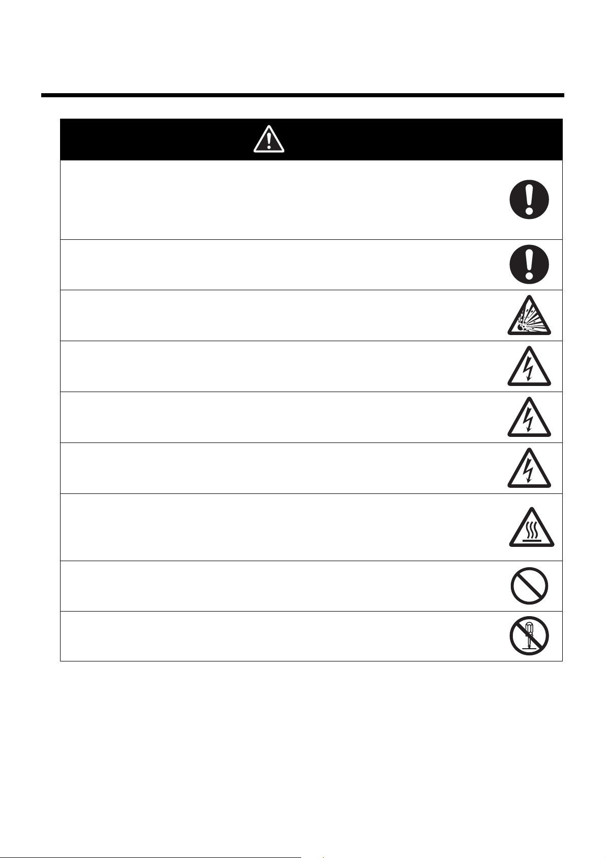
Warning displays
Indicates a potentially hazardous situation which, if not avoided, will
Caution
Meanings of the symbols
• Mandatory actions
Indicates a general action that must be performed by the user.
• Explosion caution
Indicates possibility of explosion under special conditions.
result in minor or moderate injury, or there may be property damage.
• Electrical shock caution
Indicates possibility of electric shock under special conditions.
• Disassembly prohibition
This indicates that there is the danger of electric shock or other injury if the unit
is disassembled.
• General prohibitions
Indicates a general prohibition without particular categorization.
7
Page 8
Safety precautions (continued)
Caution
Property damage may occur due to fire.
Tighten the terminal screws to the specified torques.
After tightening the screw, check that the screw is not loose.
M3.5 screw : 0.8N·m
M3 screw : 0.5 to 0.6N·m
M3 screw (KM-NCT-E's output terminal) : 0.3N·m
Minor or moderate injury or property damage may occur due to explosion.
Do not use in locations exposed to flammable or explosive gases.
Breakdown or explosion may occasionally occur.
Use the power voltage and load within the specified and rate ranges.
Electric shock may occasionally occur.
Do not touch any of the terminals while the power is being supplied.
Electric shock may occasionally occur.
Always make sure that the power to the circuit the CT is being attached to is turned
OFF before connecting the CT*.
Electric shock may occasionally occur.
Be sure to mount to coated wire with at least the basic insulation when mounting KMNCT-E.
Burns may occasionally occur.
Do not touch the product while power is being supplied or immediately after power is
turned OFF.
Use the electric wire that heat resistant temperature is 85 degrees or more when wiring
to the product.
Minor electric shock, fire, or malfunction may occasionally occur.
Do not supply a current to the CT input terminal that exceeds the maximum CT
secondary current.
Minor electric shock, fire, or malfunction may occasionally occur.
Never disassemble, modify, or repair the product.
*
CT: Current Transformer
8
Page 9

Important safety points
Observe the following to ensure safe use of model KM-N2.
• Do not use or store the product in any of the following locations.
– Locations subject to shock or vibration
– Unstable locations
– Locations subject to temperatures or humidity outside rated ranges
– Locations subject to condensation as the result of severe changes in temperature
– Outside or otherwise exposed to direct sunlight and weather
– Locations subject to static electricity or other forms of noise
– Locations exposed to electromagnetic fields
– Locations subject to exposure to water or oil.
– Locations subject to exposure to salt water spray.
– Locations subject to corrosive gases (in particular, sulfide gas and ammonia gas).
– Locations subject to dust (including iron dust).
– Locations subject to exposure to solvents
• Use AWG24 to 14 to wire the power and input voltage terminals. The heat resistant temperature of the wire is 85
degrees or more.
• Use AWG18 to 14 to wire the CT terminals. The heat resistant temperature of the wire is 85 degrees or more.
• Use AWG24 to 14 to wire the communication terminals. The heat resistant temperature of the wire is 85 degrees or
more.
• For wiring to KM-NCT-E's output terminal, use a Y-shape terminal compatible with AWG18 to 14 electric wire (with
a cross-section of 0.75 to 2.0mm
• The recommended tightening torque of the M3 screw of KM-NCT-E's output terminal is 0.3N·m.
• When mounting the KM-NCT-E to the measurement wire, push the fitting claw until it clicks.
• Be sure to wire properly with the correct terminal number. Do not wire unused terminals.
• Be sure to check that the wiring is correct before turning on the power.
• Before using or maintaining the product, thoroughly read and understand the instraction manual.
• Understand the user manual before setting the device.
• Do not pull cables.
• Use only as described in the INSTRUCTION MANUAL. Using the unit in a manner not described mayresult in the
safety functionality of the device being compromised.
• In order that workers may turn off the power immediately, install a branch circuit breaker conforming to
requirements in the country where the device is being used (USA: UL Listed, CANADA: cUL Listed, other country:
e.g. IEC60947-1 and IEC60947-3 ) and display instructions properly.
<Recommended ratings of a branch circuit breaker>
Rated current : 1A.
• Always check the wiring and confirm that it is correct before turning ON the power supply. Incorrect or improper
wiring may result in electrical shock, injury, accidents, failure, or malfunction.
• KM-NCT-E is a dedicated CT for KM-N2-FLK and KM-N3-FLK. Do not use it for other power monitors.
• The surface temperature of the CT may become high due to the heat generated by the primary power cable. Be
sure to check that the surface temperature of the CT went down before touching the CT immediately after turning
ON the power supply.
• Do not install the product close to heat-producing devices (those using coil elements, for instance).
• Ensure the screws fixing the DIN rails are tight. Also ensure that the DIN rails and the body are attached properly.
Looseness may cause the DIN rails, body, and wires to separate if vibrations or impacts occur.
• Use 35mm width DIN rails (OMRON, model PFP-50N/-100N).
• When mounting the product on the DIN rail, slide the DIN hook unit until a clicking sound is heard.
• Separate the product wiring from high-voltage or high-current power lines to prevent inductive noise. Do not place
the product wiring parallel to or in the same ducts or conduits as power lines. Use separate ducts, separate
conduits, or shielded cables to prevent noise.
• This is a “class A” product. In residential areas it may cause radio interference. The user may be required to take
adequate measures to reduce interference if this occurs.
2
) and M3 screw.
9
Page 10

Precautions for correct use
• This product is not categorized as "a specified measuring instrument" officially approved by an organization
specified in relevant measurement acts. It cannot be used to certify power usage.
• Set the parameters of the product so that they are suitable for the system being measured.
• Mount this product on DIN rails for use.
• Use varistors between the outer power and voltage measuring input wires when this product is installed in an
overvoltage category
• This product cannot be used to measure the inverter’s secondary side.
• Ensure that the rated voltage is reached within 2 seconds of turning the power on.
• Do not use thinners for cleaning. Use commercial alcohol.
• When cleaning the unit, make sure the power is off and wipe the surface of the unit with a soft dry cloth. Do not use
chemicals including solvents such as thinners, benzine, or alcohol.
• You cannot use the CT dedicated for use with the Omron KM series (model series KM20-CTF, model series KM-
NCT) . Use a CT whose secondary output is 1A or 5A.
• Use ferrule terminals to connect CTs to the CT terminals on the main unit to ensure the assembly complies with
standards.
• The data for active energy is saved at 5 minute intervals. The data for the 5 minutes preceding the unit powering off
may not be saved under some circumstances.
• Dispose of this product appropriately as industrial refuse in accordance with local and national regulations.
• This product is intended for use in industrial environments. Do not use it in residential environment.
III environment.
Trademark Information
• Modbus is a registered trademark of Schneider Electric.
• Other company names and product names in this document are the trademarks or registered trademarks of their
respective companies.
10
Page 11

Manual revision history
Revision number
Catalog no. N200-E1-03
A manual revision code appears as a suffix to the catalog number on the front cover and back cover of the manual.
Revision
number
01 A April 2016 First edition
02 July 2017 Description of operability-confirmed converter: Modified
03 May 2018 Description of dedicated CT: Added
Date of revision Reason for revision, pages revised
11
Page 12

1.Overview of the unit
1. Overview of the unit
1.1 Main features
• Supports international standards
It complies with the international IEC accuracy standards and can be connected using generic CTs.
• Multi-circuit metering
Multi-circuit metering is possible with one unit, with up to four circuits metered by 1-phase 2-wire, and up to 2
circuits metered by 1-phase 3-wire and 3-phase 3-wire. It is also possible to measure multiple 1-phase 2-wire with
different phases branching off a 1-phase 3-wire, and to simultaneously measure both 1-phase 3-wire and 1-phase
2-wire.
• Multi-address system
There can be a maximum of 4 circuits in one unit. The circuits act as independent power monitors, each able to
measure, each having different settings, and each able to be allocated different communications addresses. You
can manage individual circuits as electricity monitors from a host system, so it is easy to build a communications
system and add places for measuring.
• Pulse output
The unit has 4 ports for outputting pulses each time the active energy exceeds set values. You can allocate each
circuit a pulse output port in a multi-circuit metering setup.
• RS-485 communications
You can use the Modbus (*1) and CompoWay/F (*2) protocols for RS-485 communications.
*1. Modbus is a communications control system that conforms with the RTU Mode of the Modbus Protocol.
*2. CompoWay/F is Omron's unified communication procedure for general serial communications. It has a unified
framework format and has commands compliant with FINS which works well with Omron programmable controllers, for
instance, simplifying communications between host devices (computers for example) and components.
12
Page 13

1.2 Device configuration
Breaker
Operating power and
metered voltage
Power Monitor
Model KM-N2-FLK
For example:
PLC
Pulse output 1
Host device
RS-485
Modbus
CompoWay/F
Generic CT
Pulse output 2
Pulse output 3
Pulse output 4
Generic CT
Generic CT
Generic CT
For example:
PLC
For example:
PLC
For example:
PLC
1.Overview of the unit
• The CT of OMRON's dedicated KM series output type cannot be used with this product.
• Although a generic CT with the secondary side output of 1A or 5A can be connected, CTs dedicated for use with
KM-N2-LFK and KM-N3-FLK of 1A output type are available as listed on the table below. By using a CT listed
below in combination with a KM-N2-FLK, the CE standard is supported including the use of CT and power
monitors.
• A cable to connect the CT and power monitor is separately required.
Name Model Description
KM-NCT-E100A Rated 100A, output 1A
CT dedicated for 1A output type
KM-NCT-E250A Rated 250A, output 1A
KM-NCT-E500A Rated 500A, output 1A
13
Page 14
1.Overview of the unit
88888
888888888
88
yw
ywyw
ywyw
ywywywywyw
LCD for display (enlarged)
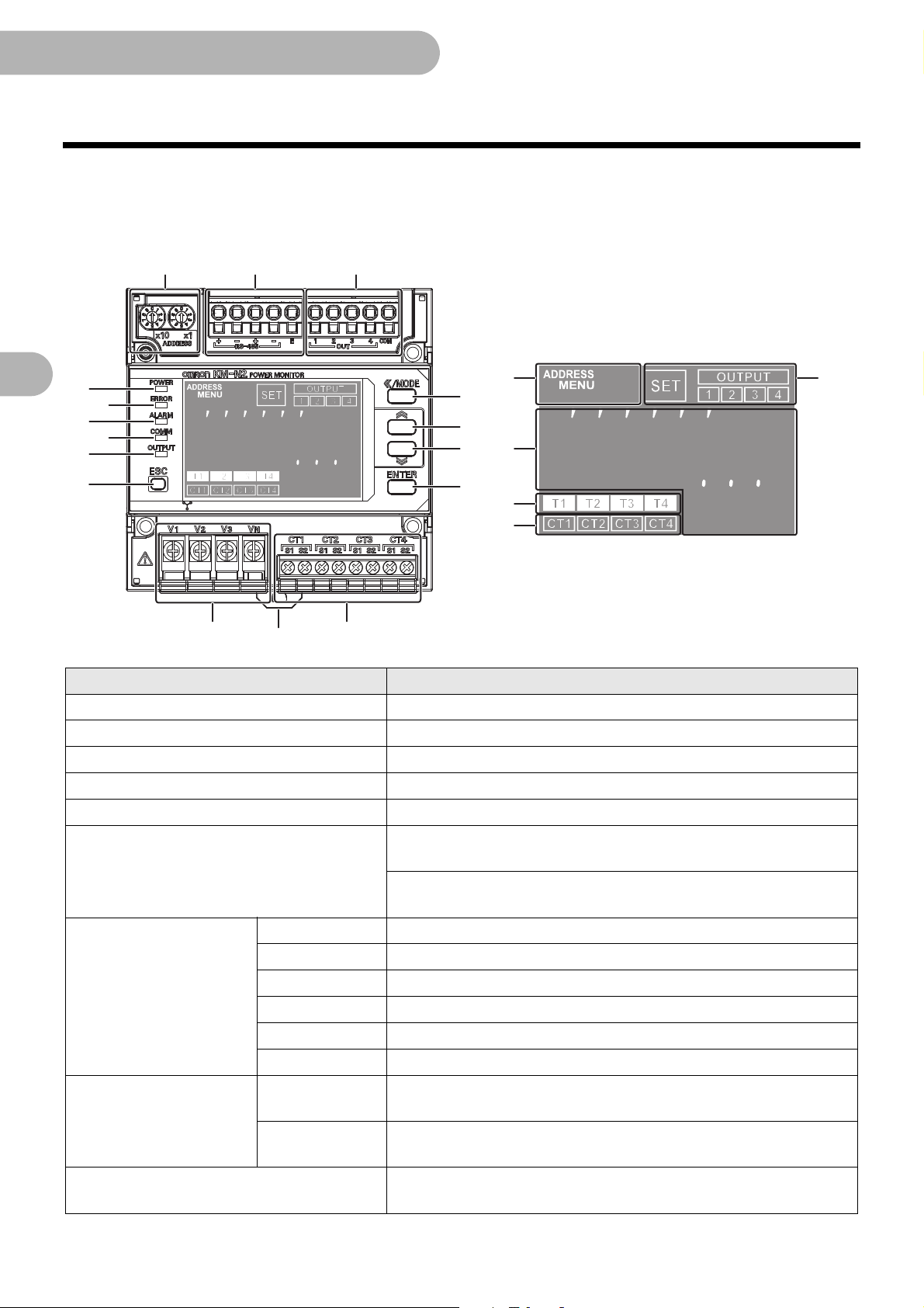
1.3 Names of the parts and their functions
[Main unit]
Front
Terminal panel cover removed
1Power LED (green) Lights when power is supplied
2Error LED (red) Flashes when there is an error such as a malfunction
3Alarm LED (orange) Flashes to indicate a warning
4Communication LED (yellow) Lights when communicating
5Pulse LED (yellow) Lights during pulse output
6Communication address/Menu display
7Status display
8Measured value/setting
value display
88
ywyw
yw
ywywywywyw
Name Description
OUTPUT Lights when setting pulse output
1 Lights when outputting pulse from OUT1
2 Lights when outputting pulse from OUT2
3 Lights when outputting pulse from OUT3
4 Lights when outputting pulse from OUT4
SET Lights in setting mode
Main display
Sub display
9Tariff display
14
888888888
ywyw
88888
When ADDRESS is illuminated (in measuring mode):
Displays the communication address
When MENU is illuminated (in setting mode):
Displays the menu number
Displays measured values and setting values (9 places on the upper
line)
Displays the units for the measured values and the names of the
setting items (5 places on the lower line)
Displays the tariff number (T1 to T4) when saving active energy
(import)
Page 15

1.Overview of the unit
1.3 Names of the parts and their functions (continued)
Name Description
:CT usage display Displays the CT number (CT1 to CT4) when measuring or setting
;<</MODE key
< Key Change setting or value (up)
= Key Change setting or value (down)
>ENTER key Confirm setting or value
?ESC key Cancels items or values
@Rotary SW
RS-485i(1) RS-485iterminal
RS-485j(1) RS-485jterminal
ARS-485 communication
terminals
BPulse output terminal
CVoltage input terminals
DCT input terminals Terminal for connecting the CT cables for CT1 to CT4
EDIN Hook Hook for attaching to the DIN rail
* Refer to "1.6 Multi-address system" ( 23) for circuit A.
RS485i(2) RS-485iterminal (for crossover wiring)
RS485j(2) RS-485jterminal (for crossover wiring)
RS485 E RS-485 terminating resistor terminals
OUT1 Pulse output 1 terminal
OUT2 Pulse output 2 terminal
OUT3 Pulse output 3 terminal
OUT4 Pulse output 4 terminal
COM Common terminal for pulse output
Short press: switch circuit/move place
Press and hold: switch mode
Sets the communication address* (left (x10): increase in units of ten,
right (x1): increase in units of 1)
Terminals for inputting the power and voltage (combined with the
input for measured voltage)
15
Page 16

1.Overview of the unit
Enlarged terminal layout label
1.3 Names of the parts and their functions (continued)
Right side surface
Name Description
FTerminal layout label
GTerminal panel cover Terminal panel cover with seal
Label with information such as the model, power voltage, connector layout, and
serial number
16
Page 17

1.Overview of the unit
(Front) (Back)
(Bottom) (Bottom (terminal cover removed))
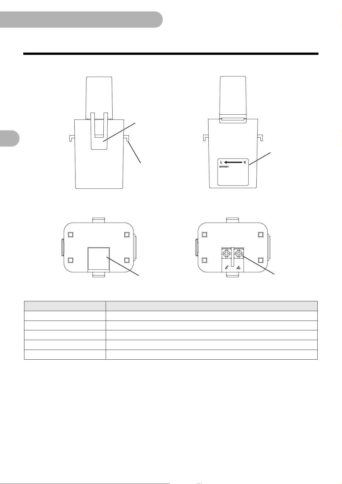
1.3 Names of the parts and their functions (continued)
[Dedicated CT]
KM-NCT-E100A, -250A
Name Function
1Label
2Output terminal block
3Terminal cover Protective cover of the output terminal block
4Fitting claw
5Fixing claw
Polarity of the primary side wiring, and models are written on this label
Secondary side current is output to this terminal block
Claw that clamps the wire and fits the top and bottom of the transformer
Used to reinforce the retention of the unit and insulation lock
17
Page 18
1.Overview of the unit
(Front) (Back)
(Bottom) (Bottom (terminal cover removed))
1.3 Names of the parts and their functions (continued)
KM-NCT-E500A
Name Function
1Label
2Output terminal block
3Terminal cover Protective cover of the output terminal block
4Fitting claw
5Fixing claw
Polarity of the primary side wiring, and models are written on this label
Secondary side current is output to this terminal block
Claw that clamps the wire and fits the top and bottom of the transformer
Used to reinforce the retention of the unit and insulation lock
18
Page 19

1.4 Dimensions
11
90
1.4
61
66.44
43
90
45
(49)
(41.2)
R20 . 3
R20 . 3
5
43
Units (mm)
(Front)
(Right side surface)
(Left side surface)
DIN rail
Part A
Part B
Part A Dimensions
of moving part
Part A Dimensions
of moving part
Part B Dimensions
of moving part
[Main unit]
1.Overview of the unit
19
Page 20

1.Overview of the unit
CT INNER DIAMETER
Units (mm)
57 (2.5)(1.5) 40.5
22
(4)(4)
ɸ36
4-R13.5
91
61
56.5
36
36
CT INNER DIAMETER
Units (mm)
1.4 Dimensions (continued)
[Dedicated CT]
KM-NCT-E100A, -250A
KM-NCT-E500A
ɸ24
45
(2.5)(1.5)
46.5
(4) (4)34
22
4-R8.5
24
24
74.5
49.5
20
Page 21

1.Overview of the unit
1.5 Multi-circuit metering
Multi-circuit metering is possible with this product. Measuring circuit refers to the measurement point where electricity
measuring is conducted. Furthermore, this product measures voltage commonly across all circuits and measures
current with each separate circuit by using generic CTs.
● Maximum number of measuring circuits for each phase
and wire type
You can connect up to 4 generic CTs to this unit. The phase and wire types and the usable number of measuring
circuits are shown in the following table.
Refer to "2.7Wiring diagrams ( 38)" for more on wiring each of the phase and wire types.
Abbreviatio
Phase and wire type
3-phase 4-wire 3P4W 1 circuit Circuit A
ns for
phase and
wire types
Maximum number of
measuring circuits
Circuits used
1-phase 2-wire 1P2W 4 circuit Circuit A, Circuit B, Circuit C, Circuit D
1-phase 3-wire 1P3W 2 circuit Circuit A, Circuit C
3-phase 3-wire 3P3W 2 circuit Circuit A, Circuit C
1-phase 2-wire
voltage selected
1-phase 3-wire
composite
• Set 1-phase 2-wire voltage selected when measuring multiple 1-phase 2-wire with different phases branching off a
1-phase 3-wire switchboard.You can measure 1-phase 2-wire by selecting the corresponding voltage.
• Set 1-phase 3-wire composite to measure both the main 1-phase 3-wire switchboard and a 1-phase 2-wire
branching off.
You can measure 1-phase 2-wire by selecting the corresponding voltage.
• Refer to "5.1Voltage assignment ( 63)" for more on 1-phase 2-wire voltage selected and 1-phase 3-wire
composite.
1P2W2 4 circuit Circuit A, Circuit B, Circuit C, Circuit D
1-phase 3-wire: 1 circuit Circuit A
1P3W2
1-phase 2-wire: 2 circuit Circuit C, Circuit D
21
Page 22

1.Overview of the unit
1.5 Multi-circuit metering (continued)
● Allocating the circuits used and the CTs for each phase
and wire type
The following table shows the phase and wire types and the CT allocations for each measuring circuits. As circuit
A is used irrespective of the phase and wire type, you must make settings for measurement ("Circuit A
settings( 54)").
By enabling circuits B to D to increase the number of measurement points ("Settings for circuits B to D (when
measuring 2 circuits or more) ( 56)"), you can meter electricity using the required number of circuits. This are
disabled by default.
Abbreviatio
Phase and wire
type
3-phase 4-wire 3P4W
1-phase 2-wire 1P2W CT1 CT2 CT3 CT4
1-phase 3-wire 1P3W CT1, CT2
3-phase 3-wire 3P3W CT1, CT2
1-phase 2-wire
voltage selected
1-phase 3-wire
composite
ns for
phase and
wire types
1P2W2 CT1 CT2 CT3 CT4
1P3W2 CT1, CT2
Circuit A Circuit B Circuit C Circuit D
CT1, CT2, CT3
Measuring circuits
CT3, CT4
CT3, CT4
CT3 CT4
22
Page 23

1.Overview of the unit
Circuit D
Measured
value
Setting
value
Communi
cation
address
For 1-phase 2-wire (maximum of 4 circuits) For 1-phase 3-wire, 3-phase 3-wire
(maximum of 2 circuits)
Model KM-N2 Model KM-N2
Circuit C
Measured
value
Setting
value
Circuit B
Measured
value
Setting
value
Circuit A
Measured
value
Setting
value
Communi
cation
address
Communi
cation
address
Communi
cation
address
Circuit A
Measured
value
Setting
value
Communi
cation
address
Circuit C
Measured
value
Setting
value
Communi
cation
address
1.6 Multi-address system
This product is a multi-address system where different communications addresses (numbered in order) are allocated
to each circuit.The communications addresses correspond to each measuring point, so data transmission
management from the host device is simplified.
The following diagram is an overview of the multi-address system.
The measurement values and setting values for individual circuits are accessed via communications addresses for
each of the circuits. The common settings are common to all of the circuits, so they can be accessed using any of the
communications addresses, which allows changes to settings for all of the circuits at once.
Refer to "6.Detailed settings for communications ( 74)" for details about commands, responses, and address maps.
Caution
• Each circuit on this product needs to be allocated different communications addresses (numbered in order).
Even if you connect several of these products on the same RS-485 line, all of the circuits need to be allocated
different communications addresses.
23
Page 24

1.Overview of the unit
Start
Circuit A
Measured
value
Circuit B
Measured
value
Circuit C
Measured
value
Circuit D
Measured
value
Measuring
mode
Setting mode
Communication
setting mode
Press
and
hold
Circuit A
Setting
item
Circuit B
Setting
item
Circuit C
Setting
item
Circuit D
Setting
item
Common
Setting
item
Others
Setting
item
Command
Change settings from
host device using RS485 communication.
Password input
Command
1.7 Mode configuration
This model has three modes: measuring mode, setting mode, and communication setting mode.
– Measuring mode: The measured values for each circuit are displayed.
– Setting mode: By operating keys on the body of the unit you can change settings for each of the circuits, and
make common settings for communications, output, the display, etc.
– Communication setting mode: Make settings on the units using RS-485 communication.
MODE
MODE
MODE
• In the measuring mode and setting mode, the circuit B to D items are displayed by switching the enable/disable
settings for each of the circuits to "ON" (enabled). (The circuits indicated inside the dotted lines in the above
diagram are "OFF" (disabled) in the default state.)
24
Page 25

2.Installation and wiring
DIN hook
Pull down
DIN rai
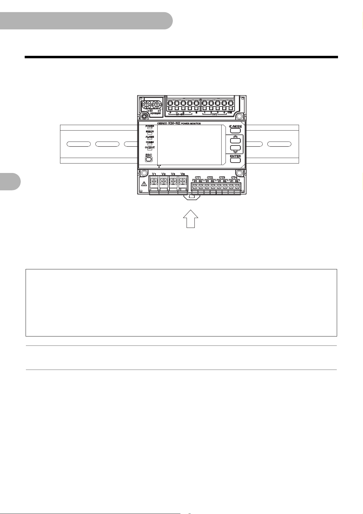
2. Installation and wiring
2.1 Attaching the body of the unit
For safety purposes, install the unit in a location where you won't touch the terminals when operating the main unit.
For example, install so that the terminals are hidden within the control board so that a person working on the unit will
not be able to touch live wires.
1 Fix the DIN rail to the installation location
– DIN rail (recommended product): Model PFP-50N/-100N (from Omron)
2 Pull down the DIN hook on the bottom of the body of the unit
3 Fit the flanges of the body onto the DIN rail as shown in the below
diagram, and click into place
25
Page 26
2.Installation and wiring
Raise
2.1 Attaching the body of the unit (continued)
4 Raise the DIN hook and fix the body to the DIN rail
Detaching the body of the unit
When removing the body from the DIN rail, use a flathead screwdriver to flick open the DIN hook and open
downwards.
Important
• Ensure that the DIN rails and the body are attached properly. Looseness may cause the DIN rails, body,
and wires to separate if vibrations or impacts occur.
• Fix end plates to the body units at each end of the DIN rail.
These stop the units from jumping off the DIN rail due to vibration or impacts.
– End plate (recommended part): model PFP-M (from Omron)
• Make sure you install so there is space for wiring above and below the body of the unit.
(about 50mm above the unit and 30mm below the unit)
Information
• You can attach multiple model KM-N2 to the DIN rail and fit the bodies next to each other.
26
Page 27

2.Installation and wiring
CT input terminals
Wiring
8mm
Under 2.7mm
Under
2.0mm
M3 screw
CT input terminals
2.2 Wiring the CTs
You can connect up to a maximum of 4 generic CTs to this unit (21). The number of CTs used depends on the phase and wire type
of the power source being monitored. The following table shows the phase and wire types and the CTs to use for each. For example,
use CT1 when measuring only one 1-phase 2-wire circuit. Further, when measuring two 1-phase 3-wire circuits, use CT1 and CT2 for
circuit A and use CT3 and CT4 for circuit C.
The layout of CT input terminals is as follows.
The following table shows the phase and wire types and the CT allocations for each measuring circuits.
Abbreviations
Phase and wire
type
3-phase 4-wire 3P4W
1-phase 2-wire 1P2W CT1 CT2 CT3 CT4
1-phase 3-wire 1P3W CT1, CT2
3-phase 3-wire 3P3W CT1, CT2
1-phase 2-wire
voltage selected
1-phase 3-wire
composite
• Connect the CT cables for CT1/CT2/CT3/CT4 to the terminals on the main unit that are labeled CT1/CT2/CT3/CT4.
• For details about how to wire the CTs, refer to the manual of the CTs you are using.
for phase
and
wire types
1P2W2 CT1 CT2 CT3 CT4
1P3W2 CT1, CT2
Circuit A Circuit B Circuit C Circuit D
CT1, CT2, CT3
Measuring circuits
CT3, CT4
CT3, CT4
CT3 CT4
Important
• Do not try to connect or disconnect CTs or CT cables during measurement or while the power of this
product is on. There is a danger of electric shock. Furthermore, this may cause this unit and the CT to
malfunction.
• For wiring to the CT input terminals, use 18 to 14 AWG (cross section surface area of 0.75 to 2.0mm
electrical wire.
• Use ferrule terminals suitable for the wire diameter to connect to the CT input terminals.
• The recommended torque for the 3mm screws is between 0.5 and 0.6Nm. Make sure the ferrule terminal
is pushed all the way in and tightened firmly. After fixing the wiring in place, pull gently to confirm that
the wiring is fixed firmly.
2
)
27
Page 28

2.Installation and wiring
2.2 Wiring the CTs (continued)
Using KM-NCT-E@@@A
The wiring method when using the KM-NCT-E@@@A, a dedicated CT for 1A output, is as follows.
• For wiring of the output terminal of CT, use AWG18-14 electric wire (with a cross-section of 0.75-2.0mm
shape terminal compatible with the M3 screw.
• The recommended torque for screwing the M3 screws onto the output terminal is 0.3 N·m. Make sure the Y
terminal is pushed all the way in and tightened firmly. After fixing the wiring, confirm that the wire is fixed securely.
• The guideline of the maximum wiring length between the main unit and CT is as follows.
Wiring diameter Guideline for wiring length limit
0.75 mm
(AWG18 equivalent)
2.0 mm
(AWG14 equivalent)
• The limit of the wiring length can also be calculated by the following formula. Calculate the wiring length limit
according to the conductor resistivity of the wiring and keep the wiring length below the limit.
• The limits of the wiring length as shown on the table and expression below are for reference only. They do not
guarantee proper use. They do not guarantee proper use.
2
15m
2
43m
2
) and Y-
Wiring extension limit value (one-way) (m) = 0.475/conductor resistivity (/m)
28
Page 29
2.Installation and wiring
Voltage input terminals
3.5mm screw
Under 6.7mm
Wiring
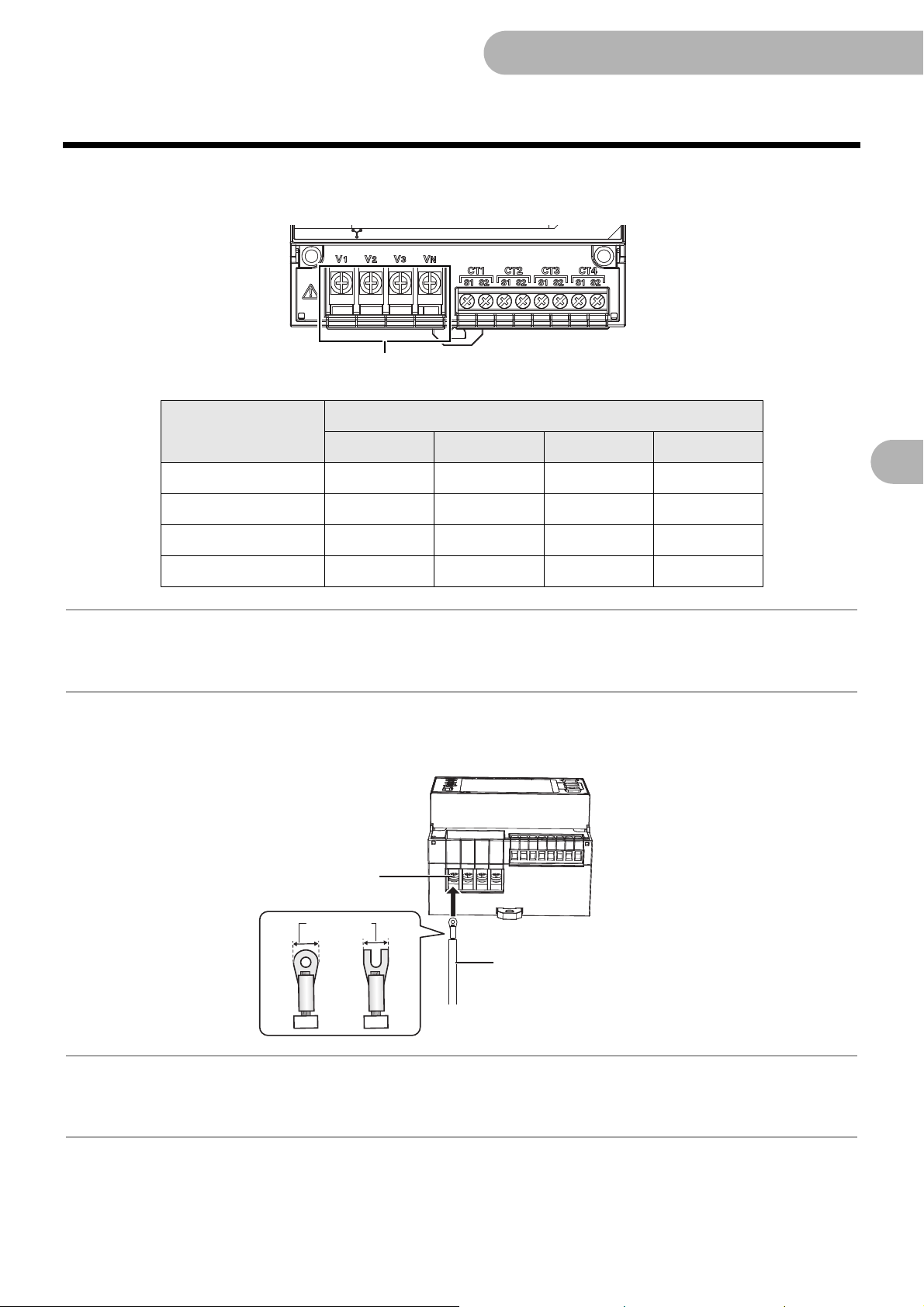
2.3 Wiring for power and monitored voltage input
Voltage input terminals V1/V2/V3/VN on this product act as both operating power terminals and as voltage measuring
terminals.
The layout of voltage input terminals is as follows.
Phase and wire type
V1 V2 V3 VN
4-phase 3-wire R S T N
1-phase 2-wire L
1-phase 3-wire R
3-phase 3-wire R S T
Information
• R/S/T/N may be labeled U/V/W/O or L1/L2/L3/N in some cases.
• R/N/T may be labeled U/O/W or L1/N/L2 in some cases.
To wire the voltage input terminal, loosen the 3.5mm screw on the terminal panel, push the wire completely into the
terminal, and fix in place with the crimping terminal.
Voltage input terminals
TN
N
Information
• The terminal panel cover fixes in place when you open it fully so it won't get in your way when you are tightening the
screws, etc.
29
Page 30

2.Installation and wiring
R
S
T
N
N
L
R
N
T
R
S
T
Branch circuit breaker
1-phase 3-wire
(1-phase 2-wire voltage selected, 1-phase 3-wire composite)
3-phase 3-wire
1-phase 2-wire3-phase 4-wire
Branch circuit breaker
Branch circuit breaker
Branch circuit breaker
2.3 Wiring for power and monitored voltage input (continued)
Wire the device according to the phase and wire type as shown in the following diagram.
Install a branch circuit breaker between the wiring for each of R/S/T/N, L/N and R/N/T so that the power can be
turned off immediately.
Important
• For safety purposes, turn off the mains power and set the branch circuit breaker to off to ensure there is
no power supply while you are working.
• Wire correctly so the phase sequence is correct. You will be unable to measure the power and energy
correctly if you fail to do so.
• For the wiring for the power and measured voltage, use 24 to 14 AWG (cross section surface area of 0.2
to 2.0mm
• The recommended torque for screwing the 3.5mm screws is 0.8Nm. Make sure the crimping terminal is
2
) electrical wire and ring or U-shaped crimp connectors suitable for 3.5mm screws.
pushed all the way in and tightened firmly. After fixing the wiring in place, pull gently to confirm that the
wiring is fixed firmly.
• During use, make sure the terminal panel cover is closed.
30
Page 31

2.Installation and wiring
CT
Power side
Load side
LoadBreaker
L
N
KL
2.4 Fitting the CTs to the measuring wires
When monitoring one circuit with 1-phase 2-wire, you need one CT. When monitoring one circuit with 1-phase 3-wire,
you need 2 CTs. When monitoring one circuit with 3-phase 4-wire, you need 3 CTs. The following diagram is an
example of fitting CTs when monitoring one circuit with 1-phase 2-wire.
• For details about how to connect the CTs to the measuring wires, refer to the manual of the CTs you are using.
• Fit the CTs to the measuring wires after connecting the CT cables to the unit.
• Attach to the L-phase if measuring 1-phase 2-wire.
Attach to the R-phase and T-phase if measuring 1-phase 3-wire or 3-phase 3-wire.
Attach to the R-phase, S-phase, and T-phase if measuring 3-phase 4-wire.
• Refer to "2.7 Wiring diagrams ( 38)" for more on attaching CTs according to the phase and wire types.
• CTs have polarity. Check the directionality of the power side (K) and the load side (L) before connecting. You will
be unable to measure correctly if you make a mistake with the directions.
Important
• Electric shock may occasionally occur.
Always make sure that the power is turned OFF before connecting the CT.
• Make sure that the primary electrical wire clamped at the CT is insulated coated wire.
• Do not expose the CTs to excessive vibrations or impacts.
31
Page 32

2.Installation and wiring
Pulse output terminal
Under
2.7mm
Under 2.7mm
8 to 10mm
Pulse output terminal
Release hole
Wiring
2.5 Pulse output wiring
Wire the pulse output terminals if using the pulse output feature. The layout of pulse output terminals is as follows.
Terminal
number
1 OUT1 Pulse output 1
2 OUT2 Pulse output 2
3 OUT3 Pulse output 3
4 OUT4 Pulse output 4
5 COM Common (common to the four outputs)
Push the wire to the very back of the pulse output terminals while pressing on the release hole.
Refer to "Cautions when connecting the Push-In Plus terminal (RS-485 communication terminal and pulse output
terminal)( 34)" for details about wiring and connections.
Terminal
name
Description
32
Page 33

2.Installation and wiring
Load Load Lo adLoad
−+
Load Load LoadLoad
PNP output connection diagramNPN output connection diagram
DC40V(max)
50mA(max)
DC40V(max)
50mA(max)
OUT2 OUT3 OUT4OUT1 COM
OUT2 OUT3 OUT 4OUT1 COM
2.5 Pulse output wiring (continued)
The following diagram shows wiring for pulse output.
This unit is equipped with 4 pulse outputs. The common terminal (number 5) is a common terminal.
−+
The table below shows the output specifications.
Output capacity DC40V, 50mA or less
Residual voltage when
ON
Current leakage when
OFF
Less than 1.5V (when output current is 50mA)
0.1mA or less
Pulse output units 1,10,100,1k,5k,10k,50k,100kWh
Pulse ON time 500ms fixed
Important
• The terminal panel is the push-in type. Also read "Cautions when connecting the Push-In Plus terminal
(RS-485 communication terminal and pulse output terminal) ( 34)" when wiring.
• Do not directly connect an external power source to OUT or COM. Make sure the load is connected.
• For wiring to the pulse output terminals, use 24 to 14 AWG (cross section surface area of 0.2 to 2.0mm
electrical wire.
• Single wires, stranded wires, and ferrule terminals can be used. The recommended stripped wire length
when using single wires or stranded wire is 8 to 10mm (however, 10mm must be used when using
AWG14).
• To avoid the influence of noise, use separate wiring for the signals and for the power.
• Output for circuit A is allocated to OUT1, circuit B to OUT2, circuit C to OUT3, and circuit D to OUT4.
These allocations are fixed.
2
)
33
Page 34

2.Installation and wiring
Terminal
(Insertion) hole
Release hole
Release hole
Terminal (Insertion) hole
Ferrules and Solid Wires
10〜12°
Flat-blade screwdriver
3
2
1
2.5 Pulse output wiring (continued)
Cautions when connecting the Push-In Plus terminal (RS-485 communication
terminal and pulse output terminal)
Follow the below steps when connecting the Push-In Plus terminal
1 Connecting Wires to Push-In Plus Terminal Block
• Part Names of the Terminal Block
• Connecting Wires with Ferrules and Solid Wires
Insert the solid wire or ferrule straight into the terminal
block until the end strikes the terminal block.
If a wire is difficult to connect because it is too thin,
use a flat-blade screwdriver in the same way as when
connecting stranded wire.
• Connecting Stranded Wires
Use the following procedure to connect the wires to
the terminal block.
1 Hold a flat-blade screwdriver at an angle and
insert it into the release hole. The angle should be
between 10e and 12e. If the flat-blade screwdriver
is inserted correctly, you will feel the spring in the
release hole.
2 With the screwdriver still inserted into the release
hole, insert the wire into the terminal hole until it
strikes the terminal block.
3 Remove the flat-blade screwdriver from the
release hole.
34
Page 35

2.5 Pulse output wiring (continued)
10〜12°
Flat-blade screwdriver
1
3
2
Side Front
2.5 dia.
2.5 mm
0.4 mm
• Checking Connections
• After the insertion, pull gently on the wire to make
sure that it will not come off and the wire is securely
fastened to the terminal block.
• To prevent short circuits, insert the stripped part of a
stranded or solid wire or the conductive part of a
ferrule until it is hidden inside the terminal insertion
hole. (See right diagram.)
2 Removing Wires from Push-In Plus
Terminal Block
Use the following procedure to remove wires from the
terminal block. The same method is used to remove
stranded wires, solid wires, and ferrules.
1 Hold a flat-blade screwdriver at an angle and
insert it into the release hole.
2 With the screwdriver still inserted into the release
hole, remove the wire from the terminal insertion
hole.
3 Remove the flat-blade screwdriver from the
release hole.
2.Installation and wiring
2 Removing Wires from Push-In Plus Terminal Block
• ecommended Flat-blade Screwdriver
Use a flat-blade screwdriver to connect and remove wires.
Use the following flat-blade screwdriver.
Model Manufacturer
XW4Z-00B Omron
35
Page 36

2.Installation and wiring
RS-485 terminal
Under 2.7mm
8 to 10mm
RS-485 terminal
Release hole
Wiring
Under
2.7mm
2.6 RS-485 wiring
Wire the RS-485 terminals if using the RS-485 communication feature. The layout of RS-485 terminals is as follows.
Terminal
number
1 RS-485
2 RS-485jjterminal for RS-485
3 RS-485
4 RS-485j RS-485jterminal (for crossover wiring)
5 RS-485 E Terminating resistor for RS-485 (ON when shorted with terminal number 4)
TTerminal number 1 and 3 and terminal number 2 and 4 are electrically connected inside this product.
Push the wire to the very back of the RS-485 terminal while pressing on the release hole.
Refer to "Cautions when connecting the Push-In Plus terminal (RS-485 communication terminal and pulse output
terminal)( 34)" for details about wiring and connections.
Terminal
name
ii
i
Description
terminal for RS-485
RS-485iterminal (for crossover wiring)
36
Page 37

2.Installation and wiring
+
−
Communications
master
(host device)
Maximum transmission distance 1200m
Terminating resistor
terminal and short
Rotary switch (units of 10)
Rotary switch (units of 1)
2.6 RS-485 wiring (continued)
The following diagram shows wiring for RS-485 communication.
The configuration of the connection should be either 1:1 or 1:N. If the 1:N connection is Modbus, up to 99 of this
product can be connected. If CompoWay/F, up to 31 can be connected. Enable the terminating resistor that shorts
terminal numbers 4 and 5 in the end unit.
Setting the communication address
When wiring is finished, turn the rotary switch to set the communication address.
The value on the left is circuit A communication address tens place and the value on the right is the ones.
Important
• The terminal panel is the push-in type. Also read "Cautions when connecting the Push-In Plus terminal
(RS-485 communication terminal and pulse output terminal) ( 34)" when wiring.
• Only the communication address for circuit A can be set with the rotary switch. Refer to "Settings for circuits B to D
(when measuring 2 circuits or more)" (
• The addresses for circuits B to D are automatically set, where 1 is added for each circuit in order to the address set
for circuit A. Refer to "Settings for circuits B to D (when measuring 2 circuits or more) (
• If the communications address exceeds 99 when multi-circuit metering, the value is invalid.
• If the host device you are using does not have its own built in terminating resistor, connect a terminating
resistor to the host device. The terminating resistance is 120Ω (1/2W).
• Do not wire in a terminating resistor terminal on any of these products that are along the transmission
path. This can cause communication failures.
• There is no FG terminal on this product. Connect only the
• Use twisted pair cables.
• For wiring to the RS-485 terminals, use 24 to 14 AWG (cross section surface area of 0.2 to 2.0mm2) electrical wire.
• Single wires, stranded wires, and ferrule terminals can be used. The recommended stripped wire length when using
single wires or stranded wire is 8 to 10mm (however, 10mm must be used when using AWG14).
• To avoid the influence of noise, use separate wiring for the RS-485 communications and for the power.
• Irrespective of the transmission distance and number of units connected, perform communications
checks with the actual units.
• During use, make sure the terminal panel cover is closed.
[Reference]
• If the upstream device does not support RS-485 communications, refer to the table below to select a converter for your purpose.
56) to set the communications addresses for circuits B to D.
56)" for details.
i
wire and j wire of RS-485.
Protocol KM-N Setting Tool USB/RS-485 converter operability confirmed
Modbus
CompoWay/F
Yes
Yes
No K3SC-10 (Omron), SI-35USB (LINEEYE Co.,Ltd.)
SI-35USB (LINEEYE Co., Ltd.)No
37
Page 38

2.Installation and wiring
RSTN
Power side
Load
Circuit A (CT1 to 3)
Branch
circuit
breaker
LN
Power side
Load
Circuit A (CT1)
Breaker
Load
Load
Load
Circuit B (CT2)
Circuit C (CT 3)
Circuit D (CT4)
Breaker
Breaker
Breaker
Branch
circuit
breaker
2.7 Wiring diagrams
The below table shows the wiring for voltage, current, and CT by each phase and wire type.
■ For 3-phase 4-wire
3-phase 4-wire measures one circuit, as shown in the following diagram.
■ For 1-phase 2-wire
As shown below, 1-phase 2-wire can measure a maximum of 4 circuits. The CT must be attached to the L-phase.
38
Page 39

2.Installation and wiring
RNT
Power side
Load
Circuit A (CT1 to 2)
Breaker
Load
Circuit C (CT 3 to 4)
Breaker
Branch
circuit
breaker
RS T
Load
Circuit A (CT1 to 2)
Load
Circuit C (CT 3 to 4)
Power side
Breaker
Breaker
Branch
circuit
breaker
2.7 Wiring diagrams (continued)
■ For 1-phase 3-wire
As shown below, 1-phase 3-wire can measure a maximum of 2 circuits. Use CT1,CT2 when measuring only 1 circuit.
The CT must be attached to the R-phase and the T-phase.
■ For 3-phase 3-wire
As shown below, 3-phase 3-wire can measure a maximum of 2 circuits. Use CT1,CT2 when measuring only 1 circuit.
The CT must be attached to the R-phase and the T-phase.
39
Page 40

2.Installation and wiring
RN
Power side
Load
Circuit A (CT1)
Breaker
Breaker
Breaker
Breaker
Load
Load
Load
Circuit B (CT2)
Circuit C (CT 3)
Circuit D (CT4)
T
Branch
circuit
breaker
RN
Power side
Load
Circuit A (CT1 to 2)
Load
Load
Circuit C (CT 3)
Circuit D (CT4)
T
Breaker
Breaker
Breaker
Branch
circuit
breaker
2.7 Wiring diagrams (continued)
The following wiring is also possible as a further method of measuring.
■ For 1-phase 2-wire voltage selected
The 1-phase 2-wire branching off from the 1-phase 3-wire is measured. With this connection, a setting is required
according to which of R-N phase, T-N phase, or R-T phase is connected to the 1-phase 2-wire circuit. ( 63) The CT
must be attached to the R-phase or the T-phase.
■ For 1-phase 3-wire composite
The 1-phase 3-wire circuit and the 1-phase 2-wire branching off from it are measured at the same time. With this
connection, a setting is required according to which of R-N phase, T-N phase, or R-T phase is connected to the 1phase 2-wire circuit. ( 63) The 1-phase 2-wire circuit CT must be attached to the R-phase or the T-phase.
40
Page 41

3.Basic use
(Example of Ver.1.0.X)
3. Basic use
3.1 Turning the power on
Important
• Before turning on the power, ensure that there are no problems with the wiring.
Turn the branch circuit breaker on and then turn this product on.
• The software version is shown on the main display, the model number "KM-N2" is shown on the sub-display, and
all of the LEDs light.
• After this, the measuring mode is moved to automatically and the active energy (import) (kWh) for circuit A is
displayed.
KM-N2
POWER
ERROR
ALARM
COMM
OUTPUT
ESC
OMRON
SMART POWER MONITOR
/MODE
10
o1 v
ENTER
2n-mk
o1v
2n-mk
oooo
hWk
41
Page 42

3.Basic use
w4p3
1a
EDOM
TES
wssap
oooo
Settingmode
Screens
<</MODE
Press and hold
Password
Authenticated
Automatic transition
Measuring mode
Settingmode
Screens
<</MODE
Press and hold
Automatic transition
Setting mode
Settingmode
Screens
<</MODE
Press and hold
Automatic transition
Setting mode
EDOM
MMOC
Measuringmode
Screens
Command
Setting mode
Command Automatic transition
EDOM
EVASMMOC
hwk
oooo
10
Command Automatic transition
3.2 Switching between modes
Switching between the measuring mode and the setting mode
Switch between the measuring mode and setting mode by pressing and holding the [<</MODE] key.
• "Press and hold" means pressing the key for 1 or more seconds.
■ Measuring mode → Setting
mode
Screen to enter the password
Enter password
(password authentication OK)
"SET MODE" displayed Setting mode
■ Setting mode → Measuring mode
1If settings are not changed in the setting mode
"MEASR MODE" displayed Measuring mode
2If settings are changed in the setting mode
"SAVE" display restart Measuring mode
– Restarting is done automatically.
rsaem
EDOM
EVAS
10
oooo
hwk
10
oooo
hwk
Switching between the measuring mode and the communication setting mode
You can switch between the communication setting mode and the measuring mode by sending particular commands.
Refer to "6.Detailed settings for communications ( 74)" for details about the commands to move to each mode.
■ Switching from measuring mode to
communication setting mode
Command sent "COMM MODE" displayed
("COMM MODE" is displayed while in communication
setting mode)
■ Switching from communication setting
42
mode to measuring mode
Command sent "MEASR MODE" displayed
Measuring mode
1If settings are not changed in the communication setting
mode
"MEASR MODE" displayed Measuring mode
2If settings are changed in the communication setting mode
"SAVE" displayed restart Measuring mode
– Restarting is done automatically.
10
rsaemMMOC
EDOM
EDOM
oooo
hwk
Page 43

3.Basic use
Command
Setting mode
12
3.2 Switching between modes (continued)
Switching between the setting mode and the communication setting mode
You can switch between the setting mode and the communication setting mode by sending particular commands.
Refer to "6.Detailed settings for communications ( 74)" for details about the commands.
It is not possible to move from the communication setting mode to the setting mode.
■ Switching from the setting mode to the
communication setting mode
Command sent "COMM MODE" displayed
("COMM MODE" is displayed while in communication setting mode)
How to enter the password
• When moving from the measuring mode to the setting mode, you need to enter the password that has been set.
• The default password is "0001".
• You can set a password of 4 numerals between 0000 and 9999. Change the password as necessary. (5.7Change
password ( 70))
MMOC
EDOM
■ Enter the password (Ex.: enter password "3060")
1 Enter "3060" with the [ ][ ] keys in the password entry screen.
– Press the [<</MODE] key to move one place to the left.
– If you press the [<</MODE] key on the end at the left, the cursor moves to the right end.
2 The password is verified when you press the [ENTER] key and "OK" is displayed.
After this, the transition to setting mode is automatic.
oooo
wssap
NG" is displayed if the password you entered was wrong.
"
Reenter the password.
o6o3
wssap
ko
wssap
gn
wssap
43
Page 44

3.Basic use
<</MODE <</MODE <</MODE
<</MODE
<</MODE <</MODE
<</MODE
<</MODE <</MODE
<</MODE
<</MODE <</MODE <</MODE
<</MODE
<</MODE <</MODE
<</MODE
3-phase 4-wire
(3P4W)
1-phase 2-wire
(1P2W)
1-phase 3-wire
(1P3W)
3-phase 3-wire
(3P3W)
selected
(1P2W2)
1-phase 3-wire
composite
(1P3W2)
Circuit A
Circuit A
Circuit A
Circuit A
Circuit BCircuit C
Circuit D
Circuit C
Circuit C
Circuit C
Circuit C
Circuit B
Circuit D
Circuit D
Circuit A
Circuit A
3.3 How to read the measurements
The measurements are shown for circuits A to D in the measuring mode. Depending on the phase and wire type
selected, the display changes as follows.
The parts in broken lines (circuits B to D) are displayed if you have enabled the circuit settings ( 56).
44
Page 45

3.Basic use
WK
2oc
hwk
oooo
20
oooo
20
-b-
20
ooOo
20
WK
2oc
hWk
oooo
30
o ooo
30
-C-
30
ooOo
30
WK
2 oc
HWk
oooo
40
oooo
40
-D-
40
ooOo
40
hwk
WK
2oc
ooOo
10
oooo
10
oooo
10
-A-
10
/MODE
/MODE/MODE/MODE
Automatic
transition
Automatic
transition
Automatic
transition
Automatic
transition
Circuit D Circuit C Circuit B Circuit A
Start
(Display example for 1-phase 2-wire (1P2W))
-a-
10
3.3 How to read the measurements (continued)
● Switching circuits
Press the [<</MODE] key to switch the circuit displayed.The measuring items are displayed after the screen for
showing the destination circuit.
• The measuring items for circuits B to D are displayed when the circuit settings are enabled (ON).
• With 3P4W, only circuit A is displayed. With 1P3W and 3P3W, only circuits A and C are displayed.
• Press the [][] keys to switch the items measured.
● Switching the measured values display
Press the [][] keys to switch the items measured. Depending on the phase and wire type, some items are not
displayed.
• Refer to "Measurement display list ( 46)" for details about measuring items.
■ Display of CTs used
The measurements are shown for each of the circuits in the measuring
mode. The CTs being used by each circuit are displayed in the display of CTs
used at this time.
For example, for 1-phase 3-wire or 3-phase 3-wire, the measurement display
for circuit A also displays CT1 and CT2 as shown at right.
45
Page 46

3.Basic use
3.3 How to read the measurements (continued)
■ Measurement display list
Order of
display
1
2
3
4
5
6
7
8
Item Main display/numerals Sub display/units Remarks
Active energy
(import)
Active power -99999.999 to 999999.999 kW
Current 1 0.000 to 999999.999
Current 2 0.000 to 999999.999
Current 3 0.000 to 999999.999
Phase voltage 1 0.0 to 99999999.9
Phase voltage 2 0.0 to 99999999.9
Phase voltage 3 0.0 to 99999999.9
0.000 to 999999.999 kWh
1000.000 to 999999.999 MWh
A_R : 3-phase 4-wire
A : 1-phase 2-wire
A_R : 1-phase 3-wire
A_R : 3-phase 3-wire
A
A (Circuit A only A_R) : 1-phase 3-wire composite
A_S : 3-phase 4-wire
None : 1-phase 2-wire
A_N : 1-phase 3-wire
A_S : 3-phase 3-wire
None
None (Circuit A only A_3) : 1-phase 3-wire composite
A_T : 3-phase 4-wire
None
A_T : 1-phase 3-wire
A_T : 3-phase 3-wire
None
None (Circuit A only A_T) : 1-phase 3-wire composite
V_R : 3-phase 4-wire
V : 1-phase 2-wire
V_R : 1-phase 3-wire
None : 3-phase 3-wire
V_R,V_T,V_R-T
V_R,V_T,V_R-T
(Circuit A onlyV_R)
None (Circuit A only V_T) : 1-phase 3-wire composite
*1
*2
V_S : 3-phase 4-wire
None : 1-phase 2-wire
None : 1-phase 3-wire
None : 3-phase 3-wire
None : 1-phase 2-wire voltage
None : 1-phase 3-wire composite
V_T : 3-phase 4-wire
None : 1-phase 2-wire
V_T : 1-phase 3-wire
None : 3-phase 3-wire
None
: 1-phase 2-wire voltage
selected
: 1-phase 2-wire voltage
selected
: 1-phase 2-wire voltage
selected
: 1-phase 2-wire voltage
selected
: 1-phase 2-wire voltage
selected
: 1-phase 3-wire composite
selected
: 1-phase 2-wire voltage
selected
Units automatically switch*
*1 Varies according to the voltage
*2 Varies according to the voltage
assignment settings
assignment settings
* The units change automatically the maximum value is reached, with the display value on the unit returning to 0, but recording
continues. Accurate values can be obtained by using the communication function.
46
Page 47

3.3 How to read the measurements (continued)
3.Basic use
Order of
display
9
10
11
12
13
14
15
16
17
18
19
20
21
22
Item Main display/numerals Sub display/units Remarks
V_R-s : 3-phase 4-wire
None : 1-phase 2-wire
None : 1-phase 3-wire
Inter-wire voltage 1 0.0 to 99999999.9
Inter-wire voltage 2 0.0 to 99999999.9
None (Circuit A only V_R-t) : 1-phase 3-wire composite
Inter-wire voltage 3 0.0 to 99999999.9
Frequency 45.0 to 65.0 Hz
Power factor -1.00 to 1.00 PF
Reactive power -99999.999 to 999999.999 kVAR
Active energy
(export)
Cumulative total
reactive power
Reactive energy
(import)
Reactive energy
(export)
T1 Active energy
(import)
T2 Active energy
(import)
T3 Active energy
(import)
T4 Active energy
(import)
0.000 to 999999.999 -kwh
1000.000 to 999999.999 -mwh
0.000 to 999999.999 kVARh
1000.000 to 999999.999 mVARh
0.000 to 999999.999 -kVRh
1000.000 to 999999.999 -mVRh
0.000 to 999999.999 +kVRh
1000.000 to 999999.999 +mVRh
0.000 to 999999.999 kwh
1000.000 to 999999.999 mwh
0.000 to 999999.999 kwh
1000.000 to 999999.999 mwh
0.000 to 999999.999 kwh
1000.000 to 999999.999 mwh
0.000 to 999999.999 kwh
1000.000 to 999999.999 mwh
V_R-s : 3-phase 3-wire
: 1-phase 2-wire voltage
None
selected
None : 1-phase 3-wire composite
V_R-t : 3-phase 4-wire
None : 1-phase 2-wire
V_R-t : 1-phase 3-wire
V_R-t : 3-phase 3-wire
: 1-phase 2-wire voltage
None
selected
V_s-t : 3-phase 4-wire
None : 1-phase 2-wire
None : 1-phase 3-wire
V_s-t : 3-phase 3-wire
: 1-phase 2-wire voltage
None
selected
None : 1-phase 3-wire composite
Units automatically switch*
Units automatically switch*
Units automatically switch*
Units automatically switch*
Units automatically switch*
Units automatically switch*
Units automatically switch*
Units automatically switch*
* The units change automatically the maximum value is reached, with the display value on the unit returning to 0, but recording
continues. Accurate values can be obtained by using the communication function.
47
Page 48

3.Basic use
3.3 How to read the measurements (continued)
Order of
display
23
24
25
26
27
28
29
30
31
32
Item Main display/numerals Sub display/units Remarks
Active energy
(import)
(resettable)
Active energy
(export)
(resettable)
Cumulative total
reactive power
(resettable)
Reactive energy
(import)
(resettable)
Reactive energy
(export)
(resettable)
T1 Active energy
(import)
(resettable)
T2 Active energy
(import)
(resettable)
T3 Active energy
(import)
(resettable)
T4 Active energy
(import)
(resettable)
Conversion value
0.000 to 999999.999 kwh (flashes)
1000.000 to 999999.999 mwh (flashes)
0.000 to 999999.999 -kwh (flashes)
1000.000 to 999999.999 -mwh (flashes)
0.000 to 999999.999 kVARh (flashes)
1000.000 to 999999.999 mVARh (flashes)
0.000 to 999999.999 -kVRh (flashes)
1000.000 to 999999.999 -mVRh (flashes)
0.000 to 999999.999 +kVRh (flashes)
1000.000 to 999999.999 +mVRh (flashes)
0.000 to 999999.999 kwh(flashes)
1000.000 to 999999.999 mwh (flashes)
0.000 to 999999.999 kwh (flashes)
1000.000 to 999999.999 mwh (flashes)
0.000 to 999999.999 kwh (flashes)
1000.000 to 999999.999 mwh (flashes)
0.000 to 999999.999 kwh (flashes)
1000.000 to 999999.999 mwh (flashes)
0.000 to 999999.999 xxx (Setting can be changed)
1000.000 to 999999.999 MXXx (Setting can be changed)
Units automatically switch*
Units automatically switch*
Units automatically switch*
Units automatically switch*
Units automatically switch*
Units automatically switch*
Units automatically switch*
Units automatically switch*
Units automatically switch*
Units automatically switch*1000.000 to 999999.999 kXXx (Setting can be changed)
* The units change automatically the maximum value is reached, with the display value on the unit returning to 0, but recording
continues. Accurate values can be obtained by using the communication function.
48
Page 49

3.Basic use
<</MODE
<</MODE
<</MODE
<</MODE
<</MODE
<</MODE
3-phase 4-wire
(3P4W)
1-phase 2-wire
(1P2W)
1-phase 3-wire
(1P3W)
3-phase 3-wire
(3P3W)
Circuit A
Circuit A
Circuit A
Circuit A
Circuit A
Circuit B
Circuit C
Circuit D
Circuit C
Circuit C
Circuit C
Circuit B
Circuit D
Circuit A
Circuit D
Circuit C
1-phase 2-wire voltage
selected
(1P2W2)
1-phase 3-wire
composite
(1P3W2)
Common
Others
Common
Others
Common
Others
Common
Others
Common
Others
Common
Others
3.4 How to read the setting values
The setting mode is organized into the categories "Individual setting items for circuits A to D", "Common settings",
and "Other settings".
Category Description
Circuits (A, B, C, D) Individual setting items for the circuits
Common (CMMN) Setting items common to all of the circuits (communication, pulse output, etc.)
Others (ETC) Settings for initializing, resetting cumulative values, etc.
Depending on the phase and wire type selected, the displayed settings change as follows. The setting items for
circuits in the broken lines are displayed if you have enabled the circuits.
49
Page 50

3.Basic use
ERIW
srdda
HWo
w2p1
1a
1o
2A
-----
7A
-A-
10
ERIW
hWO
VITCA
W2P1
1B
-----
7b
no
0B
-b-
20
spb
Wssap
LCTRP
k69
10
1ooo
d0
NMMC
SBDOM
00
HWO
TESER
2n-MK
-----
19
-- ---
29
CTE
o o1v
09
EDOM
TES
/MODE/MODE/MODE
/MODE
Circuit ACircuit B (C, D)CommonOthers
*For circuit C the MENU No. are
c0, c1, c2, c3,…c7
For circuit D the MENU No. are d0,d1, d2, d3,…d7
3.4 How to read the setting values (continued)
● How to switch setting items
When the [<</MODE] key is pressed, the setting items are displayed after the screen for showing the destination
circuit.
• The setting items for circuits B to D are displayed when the circuit settings are enabled (ON).
• Press the [][] keys to switch the setting items.
• Refer to "Setting item list ( 51)" for details about all of the setting items.
20
30
2B
3b
3A
4A
50
Page 51

3.Basic use
3.4 How to read the setting values (continued)
■ Setting item list
Cate-
gory
Cir
cuit
A
Cir
cuit
B
Cir
cuit
C
Cir
cuit
D
MENU
No.
A1
A2
A3
A4
A5
A6
A7
B0
B1
B2
B3
B4
B5
B6
B7
C0
C1
C2
C3
C4
C5
C6
C7
D0
D1
D2
D3
D4
D5
D6
D7
Setting Item
Phase and wire type
Communication address*
CT secondary side current 1A / 5A CT2ND 5A Set to match the rating of the CT to be used.
CT primary side current 1 to 99999 CT1ST 5
Voltage assignment V_R / V_T / V_R-T V-SET V_R
Pulse output ON/OFF ON / OFF OUT OFF
Active energy reset ----- 0WH ----- Clear the active energy for the circuit.
Circuit B ON/OFF ON / OFF ACTIV OFF
Phase and wire type
Communication address*
CT secondary side current 1A / 5A CT2ND 5A Set to match the rating of the CT to be used.
CT primary side current 1 to 9999 CT1ST 5
Voltage assignment V_R / V_T / V_R-T V-SET V_R
Pulse output ON/OFF ON / OFF OUT OFF
Active energy reset ----- 0WH ----- Clear the active energy for the circuit.
Circuit C ON/OFF ON / OFF ACTIV OFF
Phase and wire type
Communication address*
CT secondary side current 1A / 5A CT2ND 5A Set to match the rating of the CT to be used.
CT primary side current 1 to 99999 CT1ST 5 Set CT individually.
Voltage assignment V_R / V_T / V_R-T V-SET V_R
Pulse output ON/OFF ON / OFF OUT OFF
Active energy reset ----- 0WH ----- Clear the active energy for the circuit.
Circuit D ON/OFF ON / OFF ACTIV OFF
Phase and wire type
Communication address*
CT secondary side current 1A / 5A CT2ND 5A Set to match the rating of the CT to be used.
CT primary side current 1 to 99999 CT1ST 5 Set CT individually.
Voltage assignment V_R / V_T / V_R-T V-SET V_R
Pulse output ON/OFF ON / OFF OUT OFF
Active energy reset ----- 0WH ----- Clear the active energy for the circuit.
Display of options and input values
* The communication address can only be set using the rotary switch. You cannot set it with the [ ] and [ ] keys.
Main display
3P4W / 1P2W / 1P3W /
3P3W / 1P2W2 / 1P3W2
Modbus : --, 01 to 99,
CompoWay/F : -- 00 to 99,
3P4W / 1P2W / 1P3W /
3P3W / 1P2W2 / 1P3W2
Modbus : --, 01 to 99,
CompoWay/F : -- 00 to 99,
3P4W / 1P2W / 1P3W /
3P3W / 1P2W2 / 1P3W2
Modbus : --, 01 to 99,
CompoWay/F : -- 00 to 99,
3P4W / 1P2W / 1P3W /
3P3W / 1P2W2 / 1P3W2
Modbus : --, 01 to 99,
CompoWay/F : -- 00 to 99,
Sub display
Unit
WIRE 3P4W
ADDRS--(invalid
WIRE
ADDRS
WIRE -- Phase and wire type set in MENU No. A1
ADDRS
WIRE
ADDRS
Default
Value
3P4W: 3-phase 4-wire, 1P2W: 1-phase 2-wire
1P3W: 1-phase 3-wire, 3P3W: 3-phase 3-wire
1P2W2: 1-phase 2-wire voltage selected
1P3W2: 1-phase 3-wire composite
value)
(invalid
value)
(invalid
value)
(invalid
value)
Set a different number for each circuit.
Rated values for the primary side of the CT to
be connected.
Set CT individually.
Set the voltage phase for 1-phase 2-wire
circuits when 1P2W2 is selected.
ON: Circuit enabled, measuring and setting possible.
OFF: Circuit disabled, measuring and setting not
possible.
-- Phase and wire type set in MENU No. A1
-Set a different number for each circuit.
Rated values for the primary side of the CT to
be connected.
Set CT individually.
Set the voltage phase for 1-phase 2-wire
circuits when 1P2W2 is selected.
ON: Circuit enabled, measuring and setting possible.
OFF: Circuit disabled, measuring and setting not
possible.
-Set a different number for each circuit.
Set the voltage phase for 1-phase 2-wire
circuits when 1P2W2 or 1P3W2 is selected.
ON: Circuit enabled, measuring and setting possible.
OFF: Circuit disabled, measuring and setting not
possible.
-- Phase and wire type set in MENU No. A1
-Set a different number for each circuit.
Set the voltage phase for 1-phase 2-wire
circuits when 1P2W2 or 1P3W2 is selected.
Remarks
51
Page 52

3.Basic use
3.4 How to read the setting values (continued)
Circuit
Comm
on
CMMN
Others
ETC
MENU
No.
00
01
02
03
04
05
06
07
08
09
0A
0B
0C
0D
90
91
92
Setting Item
Protocol MODBS / COMPF PRTCL MODBS
Communication speed
Data length 7 / 8 LNGTH 8
Stop bit 1 / 2 STOP 1
Parity NONE / ODD / EVEN PRTY EVEN
Transmission wait time 00 to 99 WAIT 20
VT ratio 1.00 to 999.99 VT-R 1.00
Conversion rate 0.000 to 99.999 RATE
Conversion display units
Pulse output units
Automatic LCD off OFF / 1.0 / 5.0 / 10.0 (minutes) DISP 5.0 OFF means alight constantly
Warning ON/OFF ON / OFF ALARM ON
Tariff ON/OFF ON / OFF TARIF ON
Change password 0000 to 9999 PASSW 0001
Software version display V.1.0.0 KM-N2 ---
All active energy reset ----- 0WH ----- Clear the active energy for all circuits.
Initialize ----- RESET -----
Display of options and input values
Main display
1.2K / 2.4K /4.8K
9.6K / 19.2K / 38.4K(bps)
3 places: XXX
Each place: 0 to 9, A to Z, /, -, _
1 / 10 / 100 / 1K / 5K
10K / 50K /100K (Wh)
Sub display
Unit
BPS 9.6K
CHAR CO2
WH/P 100
Default
Value
10.000
Modbus: 8 (fixed)
CompoWay/F: Select between 7 or 8
Set the ratio between the primary voltage and
the secondary voltage when voltage using VT
is input
Set the conversion factor by which active
energy is multiplied for each circuit
Set the units for the conversion value using
any 3 characters
Set the output for the warning for voltage
miss-wiring
(Output even when pulse output warning is
OFF)
Change the password used when making
settings.
The main display shows an example when the
version is 1.0.0.
Restore the factory defaults.
All settings and all measured values are
initialized.
Remarks
52
Page 53

4.
Setting category: Circuits (A, B, C, D)
Circuit A setting items (
54)
• Phase and wire type
• CT secondary side current
• CT primary side current
• Communication address ( 37)
• Pulse output ON/OFF
Circuit B to D setting items (56)
• Circuit ON/OFF
• CT secondary side current
• CT primary side current
• Pulse output ON/OFF
Setting category: Common (CMMN)
RS-485 communications setting items (
59)
•Protocol
• Communication speed
• Data length
• Stop bit
•Parity
• Transmission wait time
Pulse output setting items (62)
• Pulse output units
Settings needed to measure electricity
4. Settings needed to measure electricity
4.1 Setting items for measuring electricity
The following are the setting items for measuring electricity.
53
Page 54

4.
12345
Automatic transition
ERIW ERIW
ERIWERIW
W4P3
1A
W4P3
1A
W3P1
1A
W3P1
1A
1234
Settings needed to measure electricity
4.2 Circuit settings
Correct measurement requires the correct settings for phase and wire type, CT secondary side, and CT primary side.
If points of measurement are added, enable the use of circuits B to D and set them.
● Circuit A settings
The following are the setting items required for measuring with circuit A.
When RS-485 communication is to be used, set the communication address beforehand ( 37).
You can cancel a change by pressing the [ESC] key before confirming the change.
1 Moving to setting mode
1 After turning on the power, the measuring mode is moved to automatically and the active energy (import)
for circuit A is displayed.
2 Press and hold the [<</MODE] key to move from the measuring mode to the password entry screen.
3 Press the [ ][ ] keys and enter the password "0001 (default value)".
– Press the [<</MODE] key to move one place to the left.
– If you press the [<</MODE] key on the end at the left, the cursor moves to the right end.
4 The password is verified when you press the [ENTER] key and "OK" is displayed.
5 The screen then moves to the settings mode and the "SET MODE" screen is shown for about 1 second.
After the "SET MODE" screen is shown for about 1 second, the screen moves to the settings category
display screen for circuit A.
10
o1v
2N-MK
oooo
hwK
oooo
wssap
1ooo
wssap
ko
wssap
tes
edom
1a
w4p3
2 Set the phase and wire type (Ex.; set to 1-phase 3-wire)
1 Transition from the settings category display screen for circuit A to the settings for circuit A is automatic.
"Phase and wire type (MENU A1)" is displayed.
2 Press the [ENTER] key to enter the setting mode. The setting value in the main display flashes.
3 Press the [ ][ ] keys to select "1P3W" (1-phase 3-wire).
4 Press the [ENTER] key to confirm your selection.
Caution
When the phase and wire type is changed, the enable/disable settings for circuits B to D are switched to "OFF"
(disabled).
54
Page 55

4.
dn2Tc dn2Tc
ERIW
dn2tcdn2Tc
A5
3A
A5
3A
W3P1
1A
A1
3A
A1
3A
12 3 4
ts1Tc ts1Tc
ts1Tcts1Tc
5
4A
5oooo
4A
o5ooo
4A
o5
4A
dn2Tc
A1
3A
12 3 4
12 3 4
Settings needed to measure electricity
4.2 Circuit settings (continued)
3 Set the CT secondary side current (Ex.: set to 1A)
1 From the circuit A setting item, press the [ ][ ] keys to move to "CT secondary current (MENU A3)".
2 Press the [ENTER] key to enter the setting mode. The setting value in the main display flashes.
3 Press the [ ][ ] keys to select "1A".
4 Press the [ENTER] key to confirm your selection.
4 Set the CT primary side current (Ex.: set to 50A)
1 From the circuit A setting item, press the [ ][ ] keys to move to "CT primary current (MENU A4)".
2 Press the [ENTER] key to enter the setting mode.
3 Press the [ ][ ] keys to change the value to "50".
– Press the [<</MODE] key to move one place to the left.
– If you press the [<</MODE] key on the end at the left, the cursor moves to the right end.
4 Press the [ENTER] key to confirm your change.
5 Set pulse output ON or OFF(MENU A6) (Ex.: set to ON)
1 From the circuit A setting item, press the [ ][ ] keys to move to "Pulse output ON/OFF (MENU A6)".
2 Press the [ENTER] key to enter the setting mode.
3 Press the [ ][ ] keys to select "ON".
4 Press the [ENTER] key to confirm your selection.
4A
o5
ts1Tctuo
6A
ffo
tuo tuo tuo
6A
ffo
6 A
no
6 A
no
55
Page 56

4.
Settings needed to measure electricity
4.2 Circuit settings (continued)
● Settings for circuits B to D (when measuring 2 circuits or more)
This product can measure up to 4 circuits. If you increase the number of circuits, you must enable the circuits and set
the items for them. ( 21) Make sure you disable those circuits you are not using.
You cannot set the communications addresses for circuits B to D individually. The values are automatically set as
follows according to the value on the rotary switch.
Phase and wire type
3-phase 4-wire
1-phase 2-wire
1-phase 3-wire
3-phase 3-wire
1-phase 2-wire
voltage selected
1-phase 3-wire
composite
Caution
• If the communications address exceeds 99 when multi-circuit metering, the value is invalid.
Circuit A Circuit B Circuit C Circuit D
(Value of Circuit A i1) (Value of Circuit A i2) (Value of Circuit A i3)
Value set on the
rotary switch
(Value of Circuit A i1) (Value of Circuit A i2) (Value of Circuit A i3)
Communication address
(Value of Circuit A i1)
(Value of Circuit A i1)
(Value of Circuit A i1) (Value of Circuit A i2)
56
Page 57

4.
1234
Automatic transition
dn2tc dn2Tc
VITca
dn2tcdn2tc
A5
3c
A5
3c
NO
0c
A1
3c
A1
3c
12 3 4
Settings needed to measure electricity
4.2 Circuit settings (continued)
1 Enable just those circuits from B to D that will be used
(Ex.: enable circuit C)
If a measured value is displayed, press and hold the [<</MODE] key and enter your password to switch to the setting
mode.
1 Press the [<</MODE] key to move to the settings category display screen for circuit C.
"Circuit C ON/OFF (MENU C0)" is displayed.
2 Press the [ENTER] key to enter the setting mode.
3 Press the [ ][ ] keys to select "ON".
4 Press the [ENTER] key to confirm your selection.
1A
W3P1
ERIW
2 0
-C-
0c
FFo
VITCA
0c
FFO
VITCA
0C
0C
no
VITCA
2 Set the CT secondary current for the circuits enabled from B to D
(Ex.: set the CT secondary current for circuit C to 1A)
1 From the circuit C setting item, press the [ ][ ] keys to move to "CT secondary current (MENU C3)".
2 Press the [ENTER] key to enter the setting mode. The setting value in the main display flashes.
3 Press the [ ][ ] keys to select "1A".
4 Press the [ENTER] key to confirm your selection.
no
VITCA
57
Page 58

4.
ts1Tc ts1Tc
dn2tc
ts1Tcts1Tc
5
4c
5oooo
4c
a1
3C
o5ooo
4c
o5
4 c
12 3 4
12 3 4
Settings needed to measure electricity
4.2 Circuit settings (continued)
3 Set the CT primary current for the circuits enabled from B to D
(Ex.: set the CT primary current for circuit C to 50A)
1 From the circuit C setting item, press the [ ][ ] keys to move to "CT primary current (MENU C4)".
2 Press the [ENTER] key to enter the setting mode.
3 Press the [ ][ ] keys to change the value to "50".
– Press the [<</MODE] key to move one place to the left.
– If you press the [<</MODE] key on the end at the left, the cursor moves to the right end.
4 Press the [ENTER] key to confirm your selection.
4 Set pulse output ON or OFF (MENU C6) (Ex.: set circuit C to ON)
1 From the circuit C setting item, press the [ ][ ] keys to move to "Pulse output ON/OFF (MENU C6)".
2 Press the [ENTER] key to enter the setting mode.
3 Press the [ ][ ] keys to select "ON".
4 Press the [ENTER] key to confirm your selection.
4c
o5
ts1Tctuo
The MENU No. for allocating pulse terminals for circuits B to D are circuit B "B6", circuit C "C6", and circuit D "D6".
Caution
• The phase and wire type is set in circuit A. The phase and wire type set for circuit A is shown in the circuit B to D
setting items (MENU B1, C1, and D1) and cannot be changed.
• Depending on the phase and wire type set for circuit A, there will be circuits that are unavailable for use.
The setting items for circuits unavailable for use will not be displayed.
• You need to set the current for the CT secondary side and CT primary side for each circuit.Confirm the rated values for the CT
you are using and set correctly.
6c
ffo
tuo tuo tuo
6c
ffo
6c
no
6 c
no
58
Page 59

4.
1
23
4
Automatic transition
1
Automatic transition
2453
Settings needed to measure electricity
4.3 RS-485 communication settings
For communications settings other than the communications address, set in the common settings in the settings
mode. All circuits will have the same setting.
• You can cancel a change by pressing the [ESC] key before confirming the change.
■ Set the protocol (Ex.: set to CompoWay/F)
This unit support the Modbus and CompoWay/F communications protocols. The initial setting is Modbus.
If a measured value is displayed, press and hold the [<</MODE] key and enter your password to switch to the setting
mode.
1 Press the [<</MODE] key to move to the common settings "CMMN" category display screen.
After this, the screen moves automatically to the common settings items and "Protocol (MENU 00)" is
displayed.
2 Press the [ENTER] key to enter the setting mode.
3 Press the [ ][ ] keys to select "COMPF".
4 Press the [ENTER] key to confirm your selection.
1A
W3P1
ERIW
nmmC
00
SBDom
LCTRP
00
SBDom
LCTRP
00
FPMoC
LCTRP
■ Set the communication speed (Ex.: set to 38.4 kbps)
1 Press the [<</MODE] key to move to the common settings "CMMN" category display screen.
2 From the common setting items, press the [ ][ ] keys to move to "Communication speed (MENU 01)".
3 Press the [ENTER] key to enter the setting mode.
4 Press the [ ][ ] keys to select "38.4K".
5 Press the [ENTER] key to confirm your selection.
1A
W3P1
ERIW
nmmC
00
SBDom
10
k69
spblctRP
10
k69
spb
10
k483
spb
00
FPMoC
LCTRP
10
k483
Spb
59
Page 60

4.
nmmC
HtGNLlctRP
HTGNL
HTGNL
HTGNL
8
20
FPMoC
00
8
20
7
20
7
20
ERIW
W3P1
1A
1
Automatic transition
2453
1
Automatic transition
2453
Settings needed to measure electricity
4.3 RS-485 communication settings (continued)
■ Set the data bit length (Ex.: set to 7 bits)
Can only be set when the protocol is CompoWay/F.
1 Press the [<</MODE] key to move to the common settings "CMMN" category display screen.
2 From the common setting items, press the [ ][ ] keys to move to "Data length (MENU 02)".
3 Press the [ENTER] key to enter the setting mode.
4 Press the [ ][ ] keys to select "7".
5 Press the [ENTER] key to confirm your selection.
Caution
• If the protocol is Modbus, the data bit length is fixed at 8bits.
■ Set the stop bit length (Ex.: set to 2 bits)
Can only be set when the protocol is CompoWay/F.
1 Press the [<</MODE] key to move to the common settings "CMMN" category display screen.
2 From the common setting items, press the [ ][ ] keys to move to "Stop bit length (MENU 03)".
3 Press the [ENTER] key to enter the setting mode.
4 Press the [ ][ ] keys to select "2".
5 Press the [ENTER] key to confirm your selection.
1A
W3P1
ERIW
Caution
• If the protocol is Modbus, then the stop bit length is automatically set according to the vertical parity setting ( 61)
as follows:
– "2" if the vertical parity is "NONE"
– "1" if the vertical parity is "ODD" or "EVEN"
nmmC
00
FPMoC
30
1
POTSlctRP
30
1
POTS
30
2
POTS
30
2
POTS
60
Page 61

4.
nmmC
YTRPlctRP
YTRP
YTRP
YTRP
NEVE
40
FPMoC
00
NEVE
40
DDO
40
DDO
40
ERIW
W3P1
1A
1
Automatic transition
2453
LCTRP
FPMoC
00
TIAW
o2
50
TIAW
o2
50
TIAW
51
50
TIAW
51
50
nmmC
ERIW
W3P1
1A
1
Automatic transition
2453
Settings needed to measure electricity
4.3 RS-485 communication settings (continued)
■ Set the vertical parity (Ex.: set to ODD)
Select "NONE" for no parity, "EVEN" for even parity, and "ODD" for odd parity.
1 Press the [<</MODE] key to move to the common settings "CMMN" category display screen.
2 From the common setting items, press the [ ][ ] keys to move to "Parity (MENU 04)".
3 Press the [ENTER] key to enter the setting mode.
4 Press the [ ][ ] keys to select "ODD".
5 Press the [ENTER] key to confirm your selection.
■ Set the transmission wait time (Ex.: set to 15 msec)
You can set the time to wait between when a response is created and when it is sent. The setting can be changed in
units of 1ms. The default value is 20ms.
1 Press the [<</MODE] key to move to the common settings "CMMN" category display screen.
2 From the common setting items, press the [ ][ ] keys to move to "Transmission wait time (MENU 05)".
3 Press the [ENTER] key to enter the setting mode.
4 Press the [ ][ ] keys to change the value to "15".
– Press the [<</MODE] key to move one place to the left.
– If you press the [<</MODE] key on the end at the left, the cursor moves to the right end.
5 Press the [ENTER] key to confirm your change.
61
Page 62

4.
Output units exceeded
ON output width (500ms)
OFF sustained width (100ms)
Basic pulse output waveform
nmmC
P/HWlctRP
P/HW
P/HW
P/HW
oo1
90
FPMoC
00
oo1
90
ko1
90
Ko1
90
ERIW
W3P1
1A
1
Automatic transition
2453
Settings needed to measure electricity
4.4 Pulse output settings
This product has 4pulse output ports (OUT1, OUT2, OUT3, OUT4).
You can set output ON or OFF for each output port in the pulse output settings.
When the active energy exceeds the output units, a pulse wave is output from the ports for which pulse output is set
to ON.
The following diagram shows pulse output waveforms. The ON output width is fixed at 500ms. The OFF sustained
width after output is 100ms.
An alarm is displayed when there is a pulse output error ( 102). A pulse output error may be either of the following
states.
• The output unit is exceeded again while still in the ON output state.
Action when error occurs: The pulse output continues for more than 500ms due to the unit being exceeded again.
• Output unit is exceeded within the OFF sustained width.
Action when error occurs: Pulse is output within the time of the OFF sustained width.
■ Set the pulse output units (Ex.: set to 10kWh/pulse)
Pulse output units settings are common to all ports. The default value is 100Wh/pulse.
You can cancel a change by pressing the [ESC] key before confirming the change.
1 Press the [<</MODE] key to move to the common settings "CMMN" category display screen.
2 From the common setting items, press the [ ][ ] keys to move to "Pulse output units (MENU 09)".
3 Press the [ENTER] key to enter the setting mode.
4 Press the [ ][ ] keys to select "10k".
5 Press the [ENTER] key to confirm your selection.
62
Page 63

5.Other Functions
Wiring diagram for 1-phase 2-wire voltage selected Wiring diagram for 1-phase 3-wire composite
L1 L2
RN
Load
Circuit A (CT1)
Breaker
T
Load
Load
Load
Circuit B (CT2)
Circuit C (CT 3)
Circuit D (CT4)
Breaker
Breaker
Breaker
Circuit A (CT1 to 2)
Circuit A (CT3)
Circuit A (CT4)
Power side
Branch
circuit
breaker
R
Power side
NT
Breaker
Breaker
Breaker
Load
Load
Load
Branch
circuit
breaker
1
Automatic transition
2453
5. Other Functions
5.1 Voltage assignment
If the phase and wire type has been set to 1-phase 2-wire voltage selected (1P2W2) or 1-phase 3-wire composite
(1P3W2), then you need to set the voltage for the 1-phase 2-wire circuit doing the measuring. Set either R-N phase
or T-N phase if the input voltage is AC100V, and set R-T phase of the input voltage is AC200V.
As the following diagram shows, the 1-phase 2-wire circuit for which the voltage allocation is set is circuit A, circuit B,
circuit C, and circuit D for 1P2W2 wiring and circuit C and circuit D in the 1P3W2 wiring diagram.
You need to allocate voltage for each circuit.
■ Set the voltage assignment (Ex.: set the voltage assignment for circuit C to V_R-T)
If a measured value is displayed, press and hold the [<</MODE] key and enter your password to switch to the setting
mode.
1 Press the [<</MODE] key to move to the settings category display screen for circuit C.
2 From the circuit C setting item, press the [ ][ ] keys to move to "Voltage assignment (MENU C5)".
3 Press the [ENTER] key to enter the setting mode.
4 Press the [ ][ ] keys to select "V_R-T".
5 Press the [ENTER] key to confirm your selection.
20
-c-
1A
2w3p1
ERIW
Information
• The MENU No. for allocating voltage for circuit A is "A5".
• The MENU No. for allocating voltage for circuits B to D are circuit B "B5" , circuit C "C5", and circuit D "D5".
0c
no
vitCATES-VtES-V
5c
r_V
TES-V TES-V
5c
r_V
5c
5c
t-r_V
t-r_V
63
Page 64

5.Other Functions
Power side
1-phase 2-wire 3-phase 3-wire1-phase 3-wire
Power side Power side
RNL NT RST
Transformer for
instrument(VT)
Transformer for
instrument(VT)
Transformer for
instrument(VT)
V
2
V
3
V
1
V
N
V
1
V
N
V
3
V
1
1
Automatic transition
2
4
5
3
5.2 Measuring high voltage
When measuring 6600V within a cubicle, for example, and the measured voltage exceeds 480V, you need to use a
transformer to convert the voltage to fit within the input voltage range of this unit. Set the multiplication factor from the
primary voltage value and the secondary voltage value. For example, if the primary voltage is 880V and the
secondary voltage is 110V, this becomes 880/110=8.00.
■ Set the VT ratio (Ex.: set to 8.00)
If a measured value is displayed, press and hold the [<</MODE] key and enter your password to switch to the setting
mode.
1 Press the [<</MODE] key to move to the common settings "CMMN" category display screen.
2 From the common setting items, press the [ ][ ] keys to move to "VT ratio (MENU 06)".
3 Press the [ENTER] key to enter the setting mode. The second decimal place of the setting value in the main
display flashes.
4 Press the [ ][ ] keys to change the value to "8.00".
– Press the [<</MODE] key to move one place to the left.
– If you press the [<</MODE] key on the end at the left, the cursor moves to the right end.
5 Press the [ENTER] key to confirm your change.
1A
W3P1
ERIW
nmmC
00
FPMoC
LCTRP
60
oo1
R-TV
60
oo1oo
R-TV
60
oo8oo
R-TV
Caution
• When measuring voltage under 480V, accuracy can be improved by directly entering the voltage rather than by
using a transformer.
60
oo8
R-TV
64
Page 65

5.Other Functions
1
Automatic transition
2
4
5
3
5.3 Display unit conversion
You can multiply the active energy for each circuit by a specified factor and display the result along with a unit. You
can convert the active energy to a monetary figure or volume of CO
numbers for the units displayed.
■ Set the conversion rate (Ex.: set to 0.300)
If a measured value is displayed, press and hold the [<</MODE] key and enter your password to switch to the setting
mode.
1 Press the [<</MODE] key to move to the common settings "CMMN" category display screen.
2 From the common setting items, press the [ ][ ] keys to move to "Conversion rate (MENU 07)".
3 Press the [ENTER] key to enter the setting mode. The third decimal place of the setting value in the main
display flashes.The decimal point cannot be changed.
4 Press the [ ][ ] keys to change the value to "0.300".
– Press the [<</MODE] key to move one place to the left.
– If you press the [<</MODE] key on the end at the left, the cursor moves to the right end.
5 Press the [ENTER] key to confirm your change.
2. You can include any 3 letters of the alphabet or
1A
W3P1
ERIW
nmmC
00
FPMoC
LCTRP
70
oooo1
ETAR
70
oooo1
ETAR
70
oo3oo
ETAR
70
oo3o
ETAR
65
Page 66

5.Other Functions
1
Automatic transition
2435
5.3 Display unit conversion (continued)
■ Set the conversion display units (Ex.: set to _KG)
If a measured value is displayed, press and hold the [<</MODE] key and enter your password to switch to the setting
mode.
1 Press the [<</MODE] key to move to the common settings "CMMN" category display screen.
2 From the common setting items, press the [ ][ ] keys to move to "Conversion display units (MENU 08)".
3 Press the [ENTER] key to enter the setting mode. The rightmost value of the setting value in the main
display flashes.
4 Press the [ ][ ] keys to change the value to "_KG".
– Press the [<</MODE] key to move one place to the left.
– If you press the [<</MODE] key on the end at the left, the cursor moves to the right end.
5 Press the [ENTER] key to confirm your change.
1A
W3P1
ERIW
Caution
• Use 3 characters, being alphanumeric characters or symbols, for the conversion display units.
Information
• If a space is required for the displayed units, you can use the underscore (_) instead.
• You can enter the following characters in each of the places in the conversion display unit setting.
Numbers: 0 to 9, alphabet: A to Z, symbols: - (hyphen), _ (underscore), and / (slash)
• If lower case letters are set from the host device by communication, they are automatically changed to upper case.
• Refer to "8.2ASCII code table ( 109)" for the ASCII codes for each of the characters.
nmmC
00
FPMoC
LCTRP
80
2OC
RAHC
80
2oC
RAHC
80
gK_
RAHC
80
GK_
RAHC
66
Page 67

5.Other Functions
nmmC
PSIDlctRP
PSID
PSID
PSID
o5
a0
FPMoC
00
o5
a0
oo1
a0
oo1
a0
ERIW
W3P1
1A
1
Automatic transition
2
4
5
3
5.4 Power saving mode
This feature turns the LCD display off after the set time elapses. When the LCD is off, it can be turned on again by
operating any key.
■ Set the automatic LCD off time (Ex.: set to 10 minutes)
If a measured value is displayed, press and hold the [<</MODE] key and enter your password to switch to the setting
mode.
1 Press the [<</MODE] key to move to the common settings "CMMN" category display screen.
2 From the common setting items, press the [ ][ ] keys to move to "Automatic LCD off(MENU A0)".
3 Press the [ENTER] key to enter the setting mode.
4 Press the [ ][ ] keys to select "10.0".
5 Press the [ENTER] key to confirm your selection.
67
Page 68

5.Other Functions
1
Automatic transition
2
4
5
3
5.5 Warning for voltage miss-wiring
This feature shows alarms when voltage phase for the phase and wire type is open, when the wrong phase sequence
(for 1-phase 3-wire, 3-phase 3-wire, and 3-phase 4-wire) is detected, when the active power is a negative value, or
when the frequency goes out of the rated range ( 102).
• If the V1 voltage phase is under 85V, this is "V
• If the V2 voltage phase is under 85V, this is "V
• If the V3 voltage phase is under 85V, this is ""V
• A phase sequence error occurs when the phase sequence for 3-phase 4-wire, 1-phase 3-wire, and 3-phase 3-wire
is incorrect.
• If the phase of the voltage and current differ and the active power is a negative value, the error is "Active power is a
negative value".
• If the frequency goes out of the range between 45 and 65Hz, the error is "Input frequency error warning".
Information
• If the alarm LED flashes, it cancels after you make corrections to the wiring and input and then restart the unit.
R open phase warning".
S open phase warning"
T open phase warning"
■ Set the warning for voltage miss-wiring (Ex.; set to OFF)
If a measured value is displayed, press and hold the [<</MODE] key and enter your password to switch to the setting
mode.
1 Press the [<</MODE] key to move to the common settings "CMMN" category display screen.
2 From the common setting items, press the [ ][ ] keys to move to "Warning ON/OFF (MENU 0B)".
3 Press the [ENTER] key to enter the setting mode.
4 Press the [ ][ ] keys to select "OFF".
5 Press the [ENTER] key to confirm your selection.
1A
W3P1
ERIW
nmmC
00
FPMoC
b0
NO
MRALAlctRP
b0
NO
MRALA
b0
FFO
MRALA
b 0
FFO
MRALA
68
Page 69

5.Other Functions
firatlctRP
firat
firat
firat
NO
c0
FPMoC
00
NO
c0
FFO
c0
FFO
c0
nmmC
ERIW
W3P1
1A
1
Automatic transition
2
4
5
3
5.6 Tariff feature
This feature allows you to select a location to save cumulative active energy data from T1 to T4.
Using the tariff feature allows you to, for example, change the location to save active energy so that you can later on
check the sum of active energy during a particular time period (for example, night and day when the electricity
charges are different).
• The current tariff default value is T1.
• The value for the current tariff can only be changed from the communication settings ( 74).
■ Set the tariff function (Ex.: set to OFF)
If a measured value is displayed, press and hold the [<</MODE] key and enter your password to switch to the setting
mode.
1 Press the [<</MODE] key to move to the common settings "CMMN" category display screen.
2 From the common setting items, press the [ ][ ] keys to move to "Tariff ON/OFF (MENU 0C)".
3 Press the [ENTER] key to enter the setting mode.
4 Press the [ ][ ] keys to select "OFF".
5 Press the [ENTER] key to confirm your selection.
69
Page 70

5.Other Functions
lctRP
FPMoC
00
WSSAP
oooo
d 0
WSSAP
1ooo
d0
WSSAP
o6o3
d0
niaga
ecno
d0
WSSAP
ko
d0
WSSAP
oooo
d0
WSSAP
o6o3
d0
nmmC
ERIW
W3P1
1A
1
Automatic transition
2
4
5
3
678
5.7 Change password
• This enables you to change the password that you need to enter when moving from the measuring mode to the
setting mode.
• You can set a password of 4 numerals between 0000 and 9999.
• The default password is "0001".
• There is no functionality to disable the password setting.
■ Set the password (Ex.: set to 3060)
If a measured value is displayed, press and hold the [<</MODE] key and enter your password to switch to the setting
mode.
1 Press the [<</MODE] key to move to the common settings "CMMN" category display screen.
2 From the common setting items, press the [ ][ ] keys to move to "Change password (MENU 0D)".
3 Press the [ENTER] key to enter the setting mode.
4 Press the [ ][ ] keys to change to "3060".
– Press the [<</MODE] key to move one place to the left.
– If you press the [<</MODE] key on the end at the left, the cursor moves to the right end.
5 "ONCE AGAIN" is displayed when you press the [ENTER] key.
6 The screen to enter the password the second time is displayed.
7 Input the password you entered in 4 (3060) again.
8 "OK" is displayed when you press the [ENTER] key, the display transitions to the "Change password
(MENU 0D)" display, and the password has been changed successfully.
NG is displayed if the password you entered the first time and the
second time are different, and the display returns to "Change password
(MENU 0D)".
Change the password again.
d0
Important
• You will be unable to reset the password if you forget it. Take care to note the password carefully when
changing it.
• If you forget the password, contact the place of purchase or the manufacturer.
70
gn
WSSAP
Page 71

5.Other Functions
( Example of Ver.1.0.0)
2n-mk
oo1v
09
cte
ERIW
W3P1
1A
1
Automatic transition
5.8 Checking software version
You can check the version of software this product is using.
■ Checking software version
If a measured value is displayed, press and hold the [<</MODE] key and enter your password to switch to the setting
mode.
1 Press the [<</MODE] key to move to the other settings "ETC" category display screen.
Next, the display automatically transitions to the "Check software version (MENU 90)" screen, displaying
the software version on the upper line and the product model on the lower line.
71
Page 72

5.Other Functions
1
3
42
5.9 Initialize
There are three different types of initialization.
(1) Resetting the active energy for each circuit
(2) Resetting the active energy for all circuits
(3) Resetting the active energy and setting values for all circuits
• Setting values remain unchanged if you do either (1) or (2).
• The settings for each of the circuits are also reset if you do (3). The unit restarts after you do this.
■ Resetting the active energy for each circuit (example: resetting circuit A)
If a measured value is displayed, press and hold the [<</MODE] key and enter your password to switch to the setting
mode.
1 From the circuit A setting items, press the [ ][ ] keys to move to "Active energy reset (MENU A7)".
2 When you press and hold the [ENTER] key, the dashes (-) reduce from the left side of the main screen.
3 Keep pressing the [ENTER] key.
4 When the dashes (-) disappear, and "DONE" flashes on the screen, the active energy for Circuit A has
been reset.
After completing initialization, "MENU 07" is displayed again.
10
-A-
Information
• The MENU No. for resetting active energy values for circuits B to D are circuit B "B7", circuit C "C7", and circuit D
"D7" .
7A
-----
HWo
7A
---
HWo
7A
-
HWo
7 A
enod
HWo
72
Page 73

5.Other Functions
1
2
4
53
Automatic transition
teser
-
29
teser
---
29
teser
-----
29
teser
enod
29
-A-
10
2N-MK
oo1V
09
cte
12 453
Automatic transition
5.9 Initialize (continued)
■ Resetting the active energy for all circuits
If a measured value is displayed, press and hold the [<</MODE] key and enter your password to switch to the setting
mode.
1 Press the [<</MODE] key to move to the other settings "ETC" category display screen.
2 From the other setting items, press the [ ][ ] keys to move to "All active energy reset (MENU 91)".
3 When you press and hold the [ENTER] key, the dashes (-) reduce from the left side of the main screen.
4 Keep pressing the [ENTER] key.
5 When the dash (-) disappears, and "DONE" flashes on the screen, the active energy for all circuits has
been reset.
After completing initialization, "MENU 91" is displayed again.
10
-A-
cte
09
oo1V
2N-MK
19
-----
HWo
19
---
HWo
19
-
HWo
19
■ Resetting the active energy and setting values for all circuits
If a measured value is displayed, press and hold the [<</MODE] key and enter your password to switch to the setting
mode.
1 Press the [<</MODE] key to move to the other settings "ETC" category display screen.
2 From the other setting items, press the [ ][ ] keys to move to "Initialize (MENU 92)".
3 When you press and hold the [ENTER] key, the dashes (-) reduce from the left side of the main screen.
4 Keep pressing the [ENTER] key.
5 When the dash (-) disappears, and "DONE" flashes on the screen, the active energy and setting values for
all circuits has been reset.
After initializing, press and hold the [<</MODE] key to move to the measuring mode and restart the unit.
enod
HWo
Information
• You can cancel the reset by pressing [ESC] before "DONE" is displayed.
73
Page 74

6
Command frame Command frame
Response frame
Allow 2ms or more waiting time on the host computer after receiving the
response before sending out the next command.
. Detailed settings for communications
6. Detailed settings for communications
6.1 Overview of communications
Using the communications features enables you to create programs on host devices (such as computers) to collect
the data measured by this product and to change its settings.
Each circuit on this product is allocated different communications addresses (numbered in order). ( 23)
Even if you connect several of these products on the same RS-485 line, all of the circuits need to be allocated
different communications addresses.
Circuits are identified by their communications addresses. These are indicated in the address maps in "
map(
98)" and the addresses for each circuit are all the same.
You can use the Modbus and CompoWay/F protocols for communication.
■ Communications specifications
( 59)
6.4 Address
Communications
protocols
Transmission
connections
Communication system 2 line half duplex
Sync method Asynchronous
Baud rate 2.4, 4.8, 9.6
Transfer code Binary ASCII
Data bit length 8 bits (fixed)
Stop bit length With parity: 1 bit
Error detection Vertical parity (none, odd
Flow control None
Interface RS-485
Retry function None
Communication
response
Transmission wait time
Transmission buffer 230 (byte)
Modbus CompoWay/F
Multi-drop (1:N connection)
, 19.2, 38.4kbps
Without parity: 2 bits
, even)
Check code: CRC-16
0 to 99 (ms), Default 20 (ms)
Vertical parity (none, odd, even)
Check code: BCC
7 or 8 bits
1 or 2 bits
* Default values are underlined.
■ Transmission procedure
The host device (a computer, for example) sends the command frame and model KM-N2 sends the response frame
that corresponds to the command content. So 1 response frame is sent in response to one command frame. The
command frame and response frame act as follows.
74
Page 75

6
. Detailed settings for communications
6.2 Modbus
● Data format
In the following explanations, values preceded by H' (as in H'02) indicate hexadecimal values.
The numbers under the frame sections are the number of bytes. Also, the transfer code is binary for Modbus.
■ Command frame
Silent
interval
3.5
characters
or more
Silent interval A non-communication time of 3.5 characters worth of time or more
Communication address • Specifies the "Communication address" of this product.
Function code Code to indicate the type of command.
Data Data text to match the function code.
CRC-16 Cyclical Redundancy Check
Commu
nication
address
Function
code
11 2 3.5
• Figures in hexadecimal format between H'01 to H'63 (01 to 99) can be set.
• Specify H'00 to communicate to all at the same time.
There will be no response if this is specified however.
This check code is for the communication address until the end of the data.
Data CRC-16
Silent
interval
characters
or more
■ Response frame when normal
Commun
ication
address
11 2
Communication address The number specified by the command from is inserted as is.
Function code Function code that was received.
Data Data received.
CRC-16 Cyclical Redundancy Check
Function
code
Data CRC-16
The communication address that returned the response.
This check code is for the communication address until the end of the data.
75
Page 76

6
. Detailed settings for communications
6.2 Modbus (continued)
■ Response frame when there is an error
Commun
ication
address
111 2
Communication address The number specified by the command from is inserted as is.
Function code In the response frame when an error occurs, the addition of "H'80" to the
Error code An exit code to describe an error.
CRC-16 Cyclical Redundancy Check
Function
code
Error
code
CRC-16
This is the communication address that returned the response.
received function code indicates that it is an error response.
For example: If the response is H'03 normally, then a response when there is
an error would be H'83.
This check code is for the communication address until the end of the data.
■ An example for CRC-16 calculation
The work for calculation (16 bit register: CRC register hereunder) is processed byte by byte in the message.
1 Make the initial value of the CRC register H'FFFF
2 Use an XOR on the lower 8 bits of the CRC register and the first byte of data, return that result to the CRC register, then
while embedding the "0", move the CRC register 1 bit to the right
3 If the bit shifted from the LSB is "0", repeat step 3 (the following bit shift process). If the bit shifted from the LSB is a "1",
use an XOR calculation on the CRC register and H'A001, returning that result to the CRC register
4 Repeat steps 3 and 4 until 8 bits worth of data has been shifted
5 If the end of the message is not reached, use an XOR on the CRC register and the next byte of data, return that result to
the CRC register and repeat step 3
6 The calculated result (the value of the CRC register) is appended to the message starting from the lower byte
Example of appending the calculated result
If the calculated CRC value is H'1234, it is appended to the command frame as below.
Commun
ication
address
11 2
Function
code
Range of CRC-16 calculation
Data CRC-16
Low High
H’34 H’12
76
Page 77

6
. Detailed settings for communications
6.2 Modbus (continued)
● List of function codes (FC)
Function code Name Description
03(H’03) Variable area reading Variable area is read successively.
16(H’10) Variable area writing Variable area is written successively.
06(H’06) Command Operations are performed according to commands.
08(H’08) Echo back test Echo back test is performed.
● List of error codes
Error code Name Description Error detection
Priority
H’01 Function code error Using an unsupported function code. 1
H’02 Variable address error Invalid value specified for variable address. 2
H’03 Variable data error Data is invalid.
• Mismatch with the number of elements
• Data outside of range
H’04 Operation error The mode is not appropriate. 4
H’05 Status error (error is occurring) A malfunction has occurred and the unit
continues to be unusable.
3
5
77
Page 78

6
. Detailed settings for communications
6.2 Modbus (continued)
● Service details
■ Variable area read (03: H’03)
This service allows you to read all variable areas.
Reading of the variable areas is conducted by setting the required data in the following command frame.To read
setting values "Parameter area list ( 100)", you need to first move to the setting mode with a command. To read
measurement values "List of variable areas (measurement values) ( 98)", you can be in either the measuring mode
or the setting mode. Also, measuring continues even while in the setting mode.
Command frame
Commu
nication
address
• Start reading address
• Number of elements
Function
code
H’03
11222
Specify the address for the measurement value or
setting data you want to read. Refer to "6.4 Address
( 98)" for the address.
map
Specify the number of pieces of data that you want to
read times 2 as the number of elements. Only the
consecutive addresses can be read in a batch.
Range: H’0002 to 0032 (2 to 50).
Start reading
address
Number of
elements
CRC-16
•CRC-16
This is a check code calculated from the
communication address until the end of the data.
Refer to "An example for CRC-16 calculation" for the
calculation. ( 76)
78
Page 79

6.2 Modbus (continued)
Response frame
6
. Detailed settings for communications
Commu
nication
address
• Byte counter
• Data 1 to n
•CRC-16
Function
code
H’03 Upper Lower Upper Lower
1 1 1 4 bytes worth of the number of elements
The number of bytes of the read data is put here.
The value of the read data is put here.
This is a check code calculated from the communication address until the end of the data.
Refer to "An example for CRC-16 calculation" for the calculation. ( 76)
Byte
Counter
Data 1 Data 1 Data 2 Data 2
Data n Data n CRC-16
Upper Lower
2
Command/Response example
The following is an example of reading voltage 1.
(Communication address: When H’01)
Command
Commu
nication
address
Response
Commu
nication
address
Function
code
01 03 0000 0002 C40B
Function
code
01 03 04 0000 0960 FC4B
Start reading
address
Byte
Coun
ter
Data 1 Data 1 CRC-16
Number of
elements
CRC-16
79
Page 80

6
. Detailed settings for communications
6.2 Modbus (continued)
■ Variable area writing (16: H’10)
Writing to the variable areas is conducted by setting the required data in the following command frame.
The parameter area can be written to. Before writing, you need to first move to the setting mode with a command.
The content written is reflected by moving to the measuring mode in response to an instruction after writing of the
parameters. Measuring continues even while in the setting mode.
Command frame
Commu
nication
address
• Start writing address
• Number of elements
Function
code
H’10 Upper Lower
1 1 2 2 1 4 bytes worth of the number
Specify the address for setting data you want to write. Refer to "6.4 Address map
Specify the number of pieces of data that you want to write times 2 as the number of elements.
Range: H’0002 to 0032 (2 to 50).
Start writing
address
Number of
elements
Byte
Counter
Data 1 Data 1
of elements
Data n Data n CRC-16
Upper Lower
( 98)" for the address.
• Byte counter
Specify the number of bytes for written data.
•CRC-16
This is a check code calculated from the communication address until the data immediately preceding.
Refer to "An example for CRC-16 calculation" for the calculation. ( 76)
80
Page 81

6.2 Modbus (continued)
Response frame
6
. Detailed settings for communications
Commu
nication
address
• Start writing address
• Number of elements
•CRC-16
Command/Response example
The following shows an example of writing when changing the phase and wire type to 1-phase 2-wire.
(Communication address: When H’01)
Address: H’2000 Written data: H’00000000
Function
code
H’10
11222
The start writing address that was received.
The number of elements that were received.
This is a check code calculated from the communication address until the data immediately preceding.
Refer to "An example for CRC-16 calculation" for the calculation. ( 76)
Start writing
address
Number of
elements
CRC-16
Command
Commu
nication
address
Response
Commu
nication
address
Function
code
01 10 2000 0002 04 0000 0000 6A6E
Function
code
01 10 04 0002 DD00
Start writing
address
Byte
Counter
Number of
elements
Number of
elements
Byte
Counter
CRC-16
Data 1 Data 1 CRC-16
81
Page 82

6
. Detailed settings for communications
6.2 Modbus (continued)
■ Command (06: H’06)
Command frame
Commu
nication
address
Function
code
H’06 H’FF H’FF
11 2 2 2
Start writing
address
Fixed Fixed
Written data CRC-16
Response frame
Commu
nication
address
• Start writing address
Set "FFFF" as the dedicated address for commands.
• Written data
The written data is 4 places consisting of the command code plus the related information. Commands are as
follows. Specify command codes using hexadecimal numbers.
Function
code
H’06 H’FF H’FF
11 2 2 2
Start writing
address
Fixed Fixed
Written data CRC-16
Instruction code Related information Instruction details
03(H’03) 00
04(H’04) 00 Move to measuring mode
07(H’07) 00 Moving to setting mode
09(H’09) 00
Resets any active energy values that
can be reset (individual units)
Initialize (any active energy values that
can be reset and setting values)
82
Page 83

6
. Detailed settings for communications
6.2 Modbus (continued)
Command/Response example
The following is an example of an instruction for clearing the active energy.
(Communication address: When H’01)
Command code: "03" Related information: "00"
Command
Commu
nication
address
01 06 FFFF 0300 891E
Response
Commu
nication
address
01 06 FFFF 0300 891E
Function
code
Function
code
Start writing
address
Start writing
address
Written data CRC-16
Written data CRC-16
■ Echo back test (08: H’08)
Command frame
Commun
ication
address
Function
code
H’08 H’00
11 2 2 2
Start writing
address
Fixed Fixed
Test data CRC-16
Response frame
Commun
ication
address
• Start writing address
• Test data
Function
code
H’08 H’00
11 2 2 2
Set "0000" as the address for the echo back test.
This is any data in 2-byte HEX format.
Start writing
address
Fixed Fixed
Test data CRC-16
83
Page 84

6
. Detailed settings for communications
6.3 CompoWay/F
● Data format
In the following explanations, values preceded by H' (as in H'02) indicate hexadecimal values. Only items expressed
as normal numerals or characters indicate ASCII characters.
The numbers under the frame sections are the number of bytes.
■ Command frame
Communication
address
STX 0 0 0 ETX
12 21 11
STX This is the start code for the communication frame (H'02).
Communication address Specify the "communications address" of this product.
Sub-address Not used for this product. Specify "00".
SID Not used for this product. Specify "0".
Command text This part describes the command.
ETX Code to indicate the end of text.
Sub-address SID Command text BCC
Fixed Fixed Fixed
• Make sure you set this code as the first byte.
• You can set a number between 00 and 99 or XX (upper case).
• Specify "XX" to communicate to all at the same time.
There will be no response if this is specified however.
• Specify the communications address between 00 and 99 (BCD). There will be no
response to any other communications address.
• Make sure you set the H'03 code as the end byte.
BCC The block check character.
• The BCC shall be the value gained from an exclusive OR (XOR) function
conducted on each byte from the communications address to ETX.
■ Example of BCC calculation
The block check character (BCC) is calculated using an exclusive OR function on each byte of the values between
the communications address and ETX, then that 8-bit data is set in the BCC section.
Communication
address
02H
BCC = 30H 30H 30H 30H 30H 30H 35H 30H 33H 03H = 35H
The calculation result 35H is set in the BCC section.
0(30H) 0(30H) 0(30H) 0(30H) 0(30H) 0(30H) 5(35H) 0(30H) 3(33H)
84
Sub-address SID Command text ETX BCC
03H
BCC calculation range
35H
Page 85

6.3 CompoWay/F (continued)
■ Response frame
6
. Detailed settings for communications
Communication
address
STX 0 0 ETX
1222 11
Exit
code
00 Normal end This indicates that the command ended normally and
0F FINS command error The specified FINS command could not be executed.
14 Format error • The numbers 0 to 9 and letters A to F are used in
16 Sub-address error • The sub-address is invalid. 1
Name Description Error detection
Sub-address Exit code Command text BCC
Fixed Fixed
that there was no error.
Determine the reason for non-execution from the FINS
response code.
command text (except in echo back tests).
• There is no SID or command text. Alternatively, there is
no command text. MRC/SRC in the command text is
incomplete.
Priority
None
3
2
• The exit code is returned as the reply when 1 command frame is received when sent to this unit.
• There is no response if the command is not complete between ETX and BCC.
• The error detection priority is the order when more than one error occurs.
■ Example exit codes
The following is an example of exit codes when the command did not end normally.
For example: When there is no command text
Command
Communication
address
STX 0 0 0 ETX
Response
Communication
address
STX 0014ETX
Sub-address SID BCC
Sub-address Exit code BCC
The exit code will be "14" (format error).
85
Page 86

6
. Detailed settings for communications
6.3 CompoWay/F (continued)
For example: The sub-address is less than 2 characters and there is no SID or FINS-mini
Command
Communication
address
STX ETX
The sub-address lacks a character
BCC
Response
Communication
address
STX 0016ETX
The sub-address is "00" and the exit code is "16" (a sub-address error).
Sub-address Exit code BCC
● The composition of the Protocol Data Unit (PDU)
Command text (or PDU) consists of the main request code (MRC), the sub-request code (SRC), and the data
required by these, and these are transferred.
Service request PDU
MRC SRC Data
Continuing on from the above MRC and SRC, main response codes (MRES) and sub-response codes (SRES) are
transferred to the response frame, and then the data is transferred.
Service response PDU (normal)
MRC SRC Response code Data
MRES SRES
If the specified command text could not be executed, then the service response PDU will consist of only the MRC/
SRC and response code.
86
Page 87

6.3 CompoWay/F (continued)
● Type code
The type codes used with this product are as follows.
■ Variable area
Variable type code Description
C0 The measured values
■ Parameter area
Variable type code Description
C000 The parameter values for
various settings
● List of services
6
. Detailed settings for communications
MRC SRC Service name Processing
01 01 Read variable area Variable area is read.
02 01 Read parameter area Parameter area is read.
02 02 Write parameter area The parameter area is written.
05 03 Read unit properties
06 01 Read controller status Operating status is read.
08 01 Echo back test Echo back test is performed.
30 05 Command Operations are performed according to commands.
The model and the communication buffer size are read.
87
Page 88

6
. Detailed settings for communications
6.3 CompoWay/F (continued)
● List of response codes
When normal end
code Name Description Priority
0000 Normal end No error. None
When an error occurs
code Name Description Priority
0401 Unsupported command This is an unsupported service function. 1
1001 Over command length The command length is too long. 2
1002 Insufficient command length The command is not long enough. 3
1003 Mismatched element and data
numbers
1100 Parameter error The parameter value is unsupported. 8
1101 Area type error An unsupported area type has been specified. 4
1103 Start writing address out of range
error
110B Response length too long The length exceeds the communications
2203 Operation error Cannot process the command. 10
3000 Status error (error is occurring) The unit is malfunctioning. 11
3003 Read only Writing to the variable area. 9
There is a mismatch between the number of
elements and the number of pieces of data.
The value of the start writing address is out of
range.
buffer.
6
5
7
88
Page 89

6
. Detailed settings for communications
6.3 CompoWay/F (continued)
● Service details
Addresses, numbers of elements, and data re shown in hexadecimal notation.
■ Variable area read (0101)
Variable area is read.
Service request PDU
MRC SRC Variable
Type
0101C0 00
22242
Start reading
address
Bit
Position
Number of
elements
Service response PDU (normal)
MRC SRC Response code Read data (For the number of elements)
0101
2 2 4 8×n(n:0 to 25)
• Variable type and address to start reading
Refer to "6.4 Address map" for the different variable types and the start reading address.
• Bit position
This product does not support bit access. Fixed at "00".
• Number of elements
Specifies the number of variables to read.
Number of elements Processing
( 98)
0000 Nothing is read and the end is normal.
(Read data is not appended to the service response PDU)
0001 to 0019 A maximum of 25 (H'19) are read and the end is normal.
• When the start reading address is an address within the variable area and the end reading address (the start
reading address plus the number of elements) exceeds the valid addresses of the variable area, then if the
number of data up to the end of the end address is within the range specified by the number of elements,
reading is done and the end is normal. In this case, the number of data read will be fewer than the number of
elements specified in the command. Further, if the start reading address is outside of the variable area, there
will be a start address out of range error.
• Response code
Refer to “List of response codes” for details about each response code. ( 88)
89
Page 90

6
. Detailed settings for communications
6.3 CompoWay/F (continued)
Example of read variable area communications
This example shows how to read the two measurement values with one command when the measurement is of
voltage 1 at 103.7V and voltage 2 at 103.6V
Command
“(H’02)
STX
Response
"(H’02)
STX
This product converts measured values to hexadecimal without decimal points for response.
H’0000040D would be 1037 (in decimal).
00 00 0 01 01 C0 0000 00 0002 (H’03) (H’42)”
Commu
nication
address
00 00 00 01 01 0000 0000040D 0000040C (H’03) (H’02)”
Commu
nication
address
Sub-
address
Sub-
address
SID MRC SRC
Exit
code
MRC SRC Respon
Variable
Type
se
code
Start
reading
address
Voltage 1 Voltage 2 ETX BCC
Bit
Positio
n
Number of
elements
ETX BCC
90
Page 91

6.3 CompoWay/F (continued)
■ Read parameter area (0201)
Parameter area is read.
Service request PDU
6
. Detailed settings for communications
MRC SRC Parameter type Start reading
address
0201C000
22444
Number of
elements
Service response PDU (normal)
MRC SRC Response
code
0201
2244448×n (n: 0 to 25)
• Variable type and address to start reading
Refer to "Address map" for the variable types and the start reading address.( 98)
• Number of elements
Specifies the number of variables to read.
Number of elements Processing
8000
8001 to 8019
Parameter
Type
Nothing is read and the end is normal.
(Read data is not appended to the service response PDU)
A maximum of 25 (H'19) are read and the end is normal.
• The uppermost but must always be set to 1.
Start
reading
address
Number of
elements
Read data
(For the number of
elements)
• When the start reading address is an address within the variable area and the end reading address (the start
reading address plus the number of elements) exceeds the valid addresses of the variable area, then if the
number of data up to the end of the end address is within the range specified by the number of elements,
reading is done and the end is normal. In this case, the number of data read will be fewer than the number of
elements specified in the command. Further, if the start reading address is outside of the variable area, there
will be a start address out of range error.
• Response code
Refer to “List of response codes” for details about each response code. ( 88)
91
Page 92

6
. Detailed settings for communications
6.3 CompoWay/F (continued)
Example of read parameter area communications
This example shows how to read two settings with one command where the phase and wire type is set to 1-phase 2-wire
and the communications address is 10
Command
"(H’02) 10 00 0 02 01 C000 1000 8002 (H’03) (H’49)”
STX
Response
"(H’02) 10 00 00 02 01 0000 1000 8002
STX
• If the phase and wire type is 1-phase 2-wire, H’00000000 is read. The communications address will be
H’0000000A=10 (decimal).
Commu
nication
address
Commu
nication
address
Sub-
address
Sub-
address
SID MRC SRC
Exit
code
MRC SRC
Phase and wire
Parameter
Type
Parameter
Type
00000000
type
Start
reading
address
Start
reading
address
0000000A (H’03) (H’08)"
Communication
Number
of
element
s
Number
of
elements
address
ETX BCC
ETX BCC
92
Page 93

6
. Detailed settings for communications
6.3 CompoWay/F (continued)
■ Write parameter area (0202)
Writing to the parameter area starts.
This service is made valid by using a command to move to the settings mode. The content written is reflected by
moving to the measuring mode in response to an instruction after writing of the parameters.
Service request PDU
MRC SRC Parameter
type
0202C000
2 2 4 4 4 8×n(n:0 to 25)
Start writing
address
Number of
elements
Written data
(For the number of
elements)
Service response PDU (normal)
MRC SRC Response code
0202
22 4
• Variable type and address to start writing
Refer to "Address map" for the different variable types and the start writing address.( 98)
• Number of elements
Specifies the number of variables to be written.
Number of elements Processing
8000
Nothing is written and the end is normal.
(Written data is not appended to the service response PDU)
8001 to 8019
• When the start writing address is an address within the variable area and the end writing address (the start
writing address plus the number of elements) exceeds the valid addresses of the variable area, then if the
number of data up to the end of the end address is within the range specified by the number of elements, writing
is done and the end is normal. In this case, the number of data written will be fewer than the number of elements
specified in the command. Further, if the start writing address is outside of the variable area, there will be a start
address out of range error.
• Response code
Refer to “List of response codes” for details about each response code. ( 88)
A maximum of 25 (H'19) are written and the end is normal.
• The uppermost but must always be set to 1.
93
Page 94

6
. Detailed settings for communications
6.3 CompoWay/F (continued)
Example of write parameter communications
Example of a command to set the CT secondary side to 1A
Command
"(H’02) 00 00 0 02 02 C000 100A 8001 00000000 (H’03) (H’48)"
STX
Response
"(H’02) 00 00 00 02 02 0000 (H’03) (H’03)”
STX
The address for the CT secondary side is 100A, and setting the used CT to 1A is H'00000000.
Commu
nication
address
Commu
nication
address
Sub-
address
Sub-
address
SID MRC SRC
Exit
code
MRC SRC
Parameter
Type
Response
code
Start
writing
address
ETX BCC
Number
element
of
s
Written data
CT used:1A
■ Read unit properties (0503)
The model and buffer size are read.
Service request PDU
MRC SRC
0503
ETX BCC
22
Service response PDU
MRC SRC Response
code
0503 00E6
22 4 10 4
• Model
The model is displayed in 10 bytes of ASCII code. Space codes are used if the model doesn't take up 10 bytes.
For example: This will be as follows for model KM-N2-FLK
KM- N2 - FLK
• Buffer size
The buffer size 230 is read as "00E6" (fixed value).
• Response code
Refer to “List of response codes” for details about each response code. ( 88)
Model Buffer size
94
Page 95

6.3 CompoWay/F (continued)
■ Controller status read (0601)
Reads operational state and error status.
Service request PDU
MRC SRC
0601
22
Service response PDU (normal)
6
. Detailed settings for communications
MRC SRC Response code Operational
state
0601
22422
• Operational state
Operational state Description
00 The unit is measuring without error.
01 An error has occurred and measuring has stopped.
• Related information
Bit position Meaning Description
B0(LSB) Memory error 0: no error, 1: error
B1 V
B2 V
B3 V
B4 Input frequency warning 0: No warning, 1: Warning
R open phase warning 0; No warning, 1: Warning
S open phase warning 0: No warning, 1: Warning
T open phase warning 0: No warning, 1: Warning
Related
information
B5 Phase sequence error 0: No warning, 1: Warning
B6 Active power is a negative value 0: No warning, 1: Warning
B7(MSB) Pulse output warning 0: No warning, 1: Warning
• If there is one pulse output warning from amongst OUT1 to 4, the B7 will be 1.
• Response code
Refer to “List of response codes” for details about each response code. ( 88)
Example of bit information for related information
If a memory error (B0) occurs, the bits in the related information of the status information appear as follows.
Displayed as "01" in the PDU.
B7 B6 B5 B4 B3 B2 B1 B0
00000001
95
Page 96

6
. Detailed settings for communications
6.3 CompoWay/F (continued)
■ Echo back test (0801)
Echo back test is performed.
Service request PDU
MRC SRC Test data
0801
2 2 0 to 200
Service response PDU (normal)
MRC SRC Response code Test data
0801
2 2 4 0 to 200
• Test data
Set any test data within the range 0 to 200.
• Response code
Refer to “List of response codes” for details about each response code. ( 88)
96
Page 97

6.3 CompoWay/F (continued)
■ Command (3005)
Used when remotely controlling the unit.
Service request PDU
6
. Detailed settings for communications
MRC SRC Instruction
code
3005
2222
Related
information
Service response PDU (normal)
MRC SRC Response code
3005
22 4
• List of command codes and related information
Related information is fixed at 00.
Instruction code Related
information
03 00 Resets any active energy values that can be reset (individual units)
04 00 Move to measuring mode
07 00 Moving to setting mode
Instruction details
09 00 Initialize (any active energy values that can be reset and setting values)
• Response code
Refer to “List of response codes” for details about each response code. ( 88)
97
Page 98

6
. Detailed settings for communications
6.4 Address map
● List of variable areas (measurement values)
Used when remotely controlling the unit.
address Item
Modbus CompoWay/F
0000 0000 Voltage 1 (V)
0002 0001 Voltage 2 (V) R
0004 0002 Voltage 3 (V) R
0006 0003 Current 1 (A)
0008 0004 Current 2 (A) R
000A 0005 Current 3 (A) R
000C 0006
Power factor
000E 0007
Frequency (Hz)
0010 0008 Active power (W) H’80000000 to H’7FFFFFFF
0012 0009 Reactive power (Var) R
0014 000A Voltage V1-V2 (V)
0016 000B Voltage V1-V3 (V) R
0018 000C Voltage V2-V3 (V) R
Parameter name Monitor value
H'00000000 to H'0098967F
(0 to 9999999)
10 times the voltage
H’00000000 to H’05F5E0FF
(0 to 99999999)
1000 times the current
H’FFFFFF9C to H’00000064
(-100 to 100)
100 times the power factor
H’000001C2 to H’0000028A
(450 to 650)
10 times the frequency
(-214748368 to 2147483647)
10 times the active and reactive power
H'00000000 to H'0098967F
(0 to 9999999)
10 times the voltage
R/W
R
R
R
R
R
R
0200 0100 Active energy (import) (not resettable) (Wh)
0202 0101 Active energy (export) (not resettable) (Wh) R
0204 0102 Reactive energy (import) (not resettable) (Varh) R
0206 0103 Reactive energy (export) (not resettable) (Varh) R
0208 0104 Cumulative total reactive power (not resettable)
020A 0105 T1 Active energy (import) (not resettable) (Wh) R
020C 0106 T2 Active energy (import) (not resettable) (Wh) R
020E 0107 T3 Active energy (import) (not resettable) (Wh) R
0210 0108 T4 Active energy (import) (not resettable) (Wh) R
0220 0110 Active energy (import) (not resettable) (kWh) R
0222 0111 Active energy (export) (not resettable) (kWh) R
0224 0112 Reactive energy (import) (not resettable) (kVarh) R
0226 0113 Reactive energy (export) (not resettable) (kVarh) R
(Varh)
H'00000000 to H'3B9AC9FF
(0 to 999999999)
Value that is 1 times each value
R
R
98
Page 99

6.4 Address map (continued)
6
. Detailed settings for communications
address Item
Modbus CompoWay/F
0228 0114 Cumulative total reactive power (not resettable)
(kVarh)
022A 0115 T1 Active energy (import) (not resettable) (kWh) R
022C 0116 T2 Active energy (import) (not resettable) (kWh) R
022E 0117 T3 Active energy (import) (not resettable) (kWh) R
0230 0118 T4 Active energy (import) (not resettable) (kWh) R
0240 0120 Active energy (import) (resettable) (Wh) R
0242 0121 Active energy (export) (resettable) (Wh) R
0244 0122 Reactive energy (import) (resettable) (Varh) R
0246 0123 Reactive energy (export) (resettable) (Varh) R
0248 0124 Cumulative total reactive power (resettable) (Varh) R
024A 0125 T1 Active energy (import) (resettable) (Wh) R
024C 0126 T2 Active energy (import) (resettable) (Wh) R
024E 0127 T3 Active energy (import) (resettable) (Wh) R
0250 0128 T4 Active energy (import) (resettable) (Wh) R
0260 0130 Active energy (import) (resettable) (kWh) R
Parameter name Monitor value
H'00000000 to H'3B9AC9FF
(0 to 999999999)
Value that is 1 times each value
R/W
R
0262 0131 Active energy (export) (resettable) (kWh) R
0264 0132 Reactive energy (import) (resettable) (kVarh) R
0266 0133 Reactive energy (export) (resettable) (kVarh) R
0268 0134 Cumulative total reactive power (resettable) (kVarh) R
026A 0135 T1 Active energy (import) (resettable) (kWh) R
026C 0136 T2 Active energy (import) (resettable) (kWh) R
026E 0137 T3 Active energy (import) (resettable) (kWh) R
0270 0138 T4 Active energy (import) (resettable) (kWh) R
0300 0180 Conversion value (e.g. JPY) R
0302 0181 Conversion value (e.g. K.JPY) R
• Current 2 is the value measured by either CT2 or CT4.
• Current 3 is the measured value calculated from current 1 and current 2.
• Figures with units of Wh and kWh can be read to the cumulative value. You can use the most easy to read
according to the changes in the cumulative value.
• Negative numbers are shown as two's complement.
• Only the consecutive address items can be read in a batch.
99
Page 100

6
. Detailed settings for communications
6.4 Address map (continued)
● Parameter area list
Address
Modbus CompoWay/F
2000 1000
2002 1001 Communication address
2010 1008 Pulse output ON/OFF
2012 1009 Voltage selected
2014 100A CT secondary side current
2016 100B CT primary side current
2200 1100
2202 1101 Communication speed
2204 1102 Data length
2206 1103 Stop bit
2208 1104 Parity
220A 1105 Transmission wait time
220C 1106 Pulse output units
Type Parameter name Setting (monitor) value R/W
Phase and wire type
Unit
Individual
setting
Protocol
Common
settings
H'00000000:1P2W
H'00000001:1P3W
H'00000002:3P3W
H'00000003:1P2W2
H'00000004:1P3W2
H'00000005:3P4W
H'00000001 to H'00000063
(1 to 99): Modbus
H'00000000 to H'00000063
(0 to 99): when CompoWay/F
H’00000000:OFF
H’00000001:ON
H'00000000:V_R
H'00000001:V_T
H'00000002:V_R-T
H’00000000:1A
H’00000001:5A
H'00000000 to H'0001869F
(0 to 99999)
1 times the current
H’00000000:CompoWay/F
H’00000001:Modbus
H'00000000:1200bps
H'00000001:2400bps
H'00000002:4800bps
H'00000003:9600bps
H'00000004:19200bps
H'00000005:38400bps
H’00000000:7bit
H’00000001:8bit
H’00000000:1bit
H’00000001:2bit
H’00000000:NONE
H’00000001:ODD
H’00000002:EVEN
H’00000000 to H’00000063
(0 to 99)
Wait time in msec units
H'00000000:1Wh
H'00000001:10Wh
H'00000002:100Wh
H'00000003:1kWh
H'00000004:5kWh
H'00000005:10kWh
H'00000006:50kWh
H'00000007:100kWh
R/W
R
R/W
R/W
R/W
R/W
R/W
R/W
R/W
R/W
R/W
R/W
R/W
100
 Loading...