

Omron KM50-C Instruction Manual
KM50-C
KM50-C
INSTRUCTION MANUAL
All Rights Reserved
Smart Power Monitor
EN
INSTRUCTION MANUAL
9911216-0 A
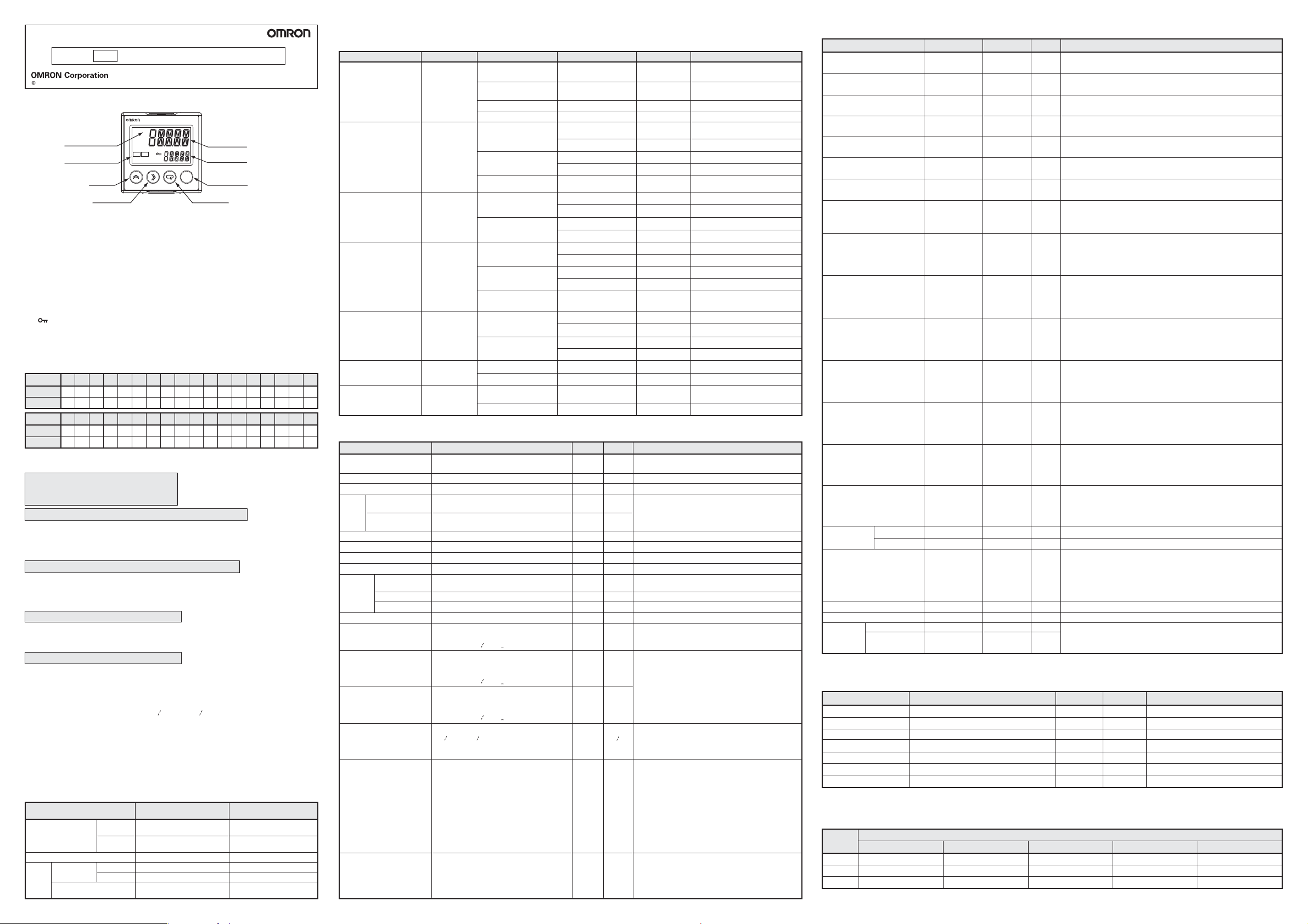
■Nomenclature
KM50-C
Temperature unit
Action indication
UP key
SHIFT key
P
OUT1 STOP
UP
SHIFT MODE ENTER
1st display
2nd display
ENTER key
MODE key
■Display Screen
1) 1st display
Displays the measurement value or type of setting data.
2) 2nd display
Displays the unit or the parameter name of the measurement data or setting data.
3) Operation display
・OUT1:
・STOP:
The light turns ON in conjunction with the output set to the OUT1 terminal.
Lights ON when power is supplied after the time measurement function stops
following back-up power failure during power OFF. Lights OFF by setting time data.
When using the product with lights ON, measurement data log cannot be recorded.
・ (Key): Lights ON at protect setting.
4) Temperature unit
When selecting Celsius in the temperature unit setting, °C is shown.
When choosing Fahrenheit, °F is shown.
■Segment display
R
7SEG
11SEG
7SEG
11SEG
aAbBcCdDeEfFgGhHiIGJHKlLIMNNoOpPJQK
abcdefghijk lmnopqr
S
T
U
V
W
X
Y
Z
0
1
2
3
4
5
6
s
t
u
W
X
Y
y
Z
Y
1
2
3
4
5
6
s
t
u
v
w
x
y
z
0
1
2
3
4
5
6
9
7
8
9
7
8
9
7
8
■Basic usage
Setting Examples
Applicable circuit type: 1-phase 3-wire
Dedicated CT type: 5ACT
Time: March 5, 2010, 17:15
A. After checking the wiring, turn ON the power supply.
“Hm50c” is displayed and EEPROM is read (“wait” is displayed for 16 sec max).
When the power is turned ON for the first time, “e-t1” is displayed and STOP
turns ON because time has not been set. 3 sec later, active power in measurement mode is displayed. (STOP remains ON).
B. Set applicable circuit type to 1-phase 3-wire.
1. Press the M key for more than 3 sec to go to applicable circuit type “00.typ”
in operation setting mode.
2. Press the U key to shift to setting state. Press the U key to change the
applicable circuit type from “3p3w” to “1p3w”, and then press the O key to confirm.
C. Set dedicated CT type to 5ACT.
1. Press the S key to move to dedicated CT type “01.c.rg”.
2. Press the U key to shift to setting state. Press the U key to change the
dedicated CT type from “100a” to “5a”, and then press the O key.
D. Set the time to March 5, 2010, 17:15.
To use the log function, time setting is required.
1. Press the S key to move to time setting “11.tim”.
2. Press the U key to shift to setting state.
Check that the year is "2010”, and then press the O key.
Change the value of Month/Date with the U key and shift the digit with the S
3.
key to change the value from
4.
Change the value of Hour-Minute with the U key and shift the digit with the S
“
01 01
”
to
“
03 05
”
, and then press the O key.
key to change the value from “00-00” to “17-15”, and then press the O key.
The content of the time setting will be saved and STOP will be turned OFF.
5. Press the M key for more than 3 sec to move to measurement mode
(measurement start). When you move to measurement mode, the setting will
be saved and “save” is displayed.
This completes the basic settings.
■Mode configuration and key operation
1) Mode configuration
Mode Group Meaning
Measurement
mode
Protect setting mode Limit the function
Operation
Setting
setting mode
mode
Communication
setting mode
Basic level
Pro level
Basic level
Pro level Set the Pro level function
Read the measurement
data of the basic level
Read the measurement
data of the Pro level
Set the basic level function
Set the communication
function
Necessity of operation
and setting
Operate only at reading
Operate only at reading
Set only when needed
Setting required at first setting
Set only when needed
Set only when using the
communication function
2) Key operation
Monitoring state is a state in which setting value is displayed in protect setting mode and setting mode.
Setting state is a state in which setting can be changed.
Symbol
O
ENTER key
M
MODE key
S
SHIFT key
U
UP key
M+S
(Press the S
key while holding
the M key)
M+U
(Press the
U key while
holding the M key)
M+O
Basic Meaning
・Mode switching
・Determination
・Mode switching
・Cancel
・Transition
・Shift to
setting state
・Change the
setting value
・Reverse
transition
・Change the
setting value
in reverse
・Mode switching
Mode State
Measurement mode
Protect setting mode,
Setting mode
Operation setting mode
Communication setting mode
Measurement mode
Setting mode
Measurement mode,
Setting mode
Measurement mode
Setting mode
Measurement mode
Setting mode
Measurement mode,
Setting mode
Measurement mode
Setting mode
Measurement mode
Setting mode
Measurement mode
Protect setting mode
Operation
Measurement history
(current day)
Setting state Determine the setting value.
Monitoring state
Monitoring state Move to operation setting mode.
Present measurement value,
measurement history
Measurement history
Monitoring state Move to measurement mode.
Setting state Cancel setting state.
Pro level Move to “PROLV” of the basic level.
Present measurement value
Measurement history
Monitoring state Change parameters.
Setting state Change digits.
Present measurement value
Measurement history
Monitoring state Shift to setting state.
Setting state Change the setting value.
Basic level (“PROLV”
remains displayed)
Present measurement value
Measurement history
Monitoring state Change parameters in reverse.
Setting state Change digits in reverse.
Measurement history
Setting state
Present measurement value,
measurement history
Monitoring state Move to measurement mode.
press for more
than 3 sec
click
click
click
press for more
than 3 sec
click
press for more than 3 sec
click
click
click
click
click
click
click
click
click
click
click
click
click
click
click
click
click
press for more
than 3 sec
press for more than 3 sec
Clear the currently displayed MAX
and MIN value of the present day.
Move to communication setting mode.
Move to operation setting mode.
Move to present measurement value.
Change parameters.
Switch measurement history display.
Move to measurement history.
Move from measurement history.
Move to Pro level.
Change parameters in reverse.
Switch the measurement history display.
Transit measurement history in reverse.
Change the setting value in reverse.
Move to protect setting mode.
■Setting mode
Operation setting modeBasic level
Item Setting range (1st display)
Applicable circuit type
Dedicated CT type
Rated primary side current value
VT
VT primary side
setting
voltage value
VT secondary side
voltage value
Current low-cut value Unit
Pulse output unit Unit
Display refresh period off is instantly updated.Unit
Averaging times.
Simple
measurement
setting
CO
Charge conversion setting
(Rate setting and price
unit setting)
Pulse conversion 1 setting
(Pulse conversion target,
factor, decimal point
position and display unit)
Pulse conversion 2 setting
(Pulse conversion target,
factor, decimal point
position and display unit)
Time setting
(Year, month/day,
hour/minute)
Initialization
Moving average time
Setting
Simple
measurement
Fixed voltage value.
Fixed power factor value.
conversion factor
2
1p2w, 1p3w, 3p3w 00.typ 3p3w
5a, 50a, 100a, 200a, 400a, 600a
5
to
9999 02.sct 5
none, 220, 440, 3300, 6600, 11000,
22000, 33000
110, 220 110
0.1
to
19.9
1, 10, 100, 1k, 2k, 5k, 10k, 20k, 50k, 100k
off, 0.5, 1.0, 2.0, 4.0 06.ref 1.0
off, 2, 4, 8, 16, 32, 64, 128, 256, 512, 1024
off, on 08.smp off
to
9999.9 vlt 110.0
0.0
to
1.00 pf 1.00
0.00
0.000
to
99.999 10.co2 0.387
0.000
to
99.999
jpy, usd, eur, cny, krw
to
z, 0
to
to
to
to
z, 0
to
z, 0
to
to
to
9, , -, (Space)
9999
to
9, , -, (Space)
9999
to
9, , -, (Space)
2099
12 31
23-59
a
c-t.d, c-1.d, c-2.d, c-t.a, c-1.a, c-2.a
0000
0000, 000.0, 00.00, 0.000
a
c-t.d, c-1.d, c-2.d, c-t.a, c-1.a, c-2.a
0000
0000, 000.0, 00.00, 0.000
a
2010
01 01
00-00
set, max, min, integ, m.pro, log, all 15.ini set
001〜120 16.avt 120
2nd display Initial value
01.c.rg 100a
03.v.rg none
v.rg2
04.cut 0.6
05.pl5 100
07.avg 8
11.chg 10.000
jpy
12.cv1 c-1.d
0001
0000
m3-1
13.cv2 c-2.d
0001
0000
m3-2
14.tim 2010
01 01
00-00
Remarks
1p2w: 1-phase 2-wire, 1p3w: 1-phase 3-wire,
3p3w: 3-phase 3-wire
Effective only when the dedicated CT type is 5A.
When the simple measurement is ON, sequentially
measure the reactive voltage, VT primary voltage,
and VT secondary voltage.
Unit: V
:
%
:
Wh
At ON, set voltage and power factor,
Frequency is 50 Hz fixed.
Can be set only at simple measurement ON.
Can be set only at simple measurement ON.
Unit
:
kg-CO2/kWh
Sequentially set the rate and price unit display.
4-digit price unit can be set.
Sequentially set the pulse conversion target, conversion factor, display unit. 4-digit display unit can be set.
c-t.d: Sum of pulse input counts
:
Pulse input count 1
c-1.d
:
Pulse input count 2
c-2.d
:
Sum of total pulse input counts
c-t.a
c-1.a
:
Total pulse input count 1
c-2.a
:
Total pulse input count 2
Year, month/day, and hour/minute should be set
continuously. If it was canceled in process, all
values will return to previous values. As soon as
setting hour and minute, the settings are reflected.
:
Initialize all setting values except time setting.
set
max: Initialize all the max value of parameters of
the present day.
:
Initialize all the min value of parameters of
min
the present day.
:
Initialize the total integral power consumption.
integ
m.pro: Initialize the measurement values in the Pro
level in measurement mode of the present day.
log: Initialize all the measurement histories.
all
:
Initialize set values other than clock time
and all measurement histories.
Set the moving average time of the Moving
average Current.
Cancel it during the input or set a value out of the
range, come back before a change.
Description
:
Sec
Operation setting modePro level
Item
Event input setting p.csp
Event input 1 NPN/PNP
input mode setting
Event input 2 NPN/PNP
input mode setting
Event input 1 N-O/N-C
input mode setting
Event input 2 N-O/N-C
input mode setting
Measurement start time (*1)
Measurement end time (*1)
Output terminal 1
function setting
Active power alarm output
(Upper/lower thresholds,
hysteresis and OFF-/ON-delay)
Regenerated power alarm
output
(Upper/lower thresholds,
hysteresis and OFF-/ON-delay)
Current alarm output
(Upper/lower thresholds,
hysteresis and OFF-/ON-delay)
Voltage alarm output
(Upper/lower thresholds,
hysteresis and OFF-/ON-delay)
Power factor alarm output
(Upper/lower thresholds,
hysteresis and OFF-/ON-delay)
Reactive power alarm output
(Upper/lower thresholds,
hysteresis and OFF-/ON-delay)
Integral power consumption
saving selection
Automatic rotation
setting
Measurement parameter
display selection
Display lighting time
Incorrect voltage wiring detection
Simple
temperature
setting
*1 It applies to the pulse input count, power consumption rate, pulse input ON time.
*2 When thresholds or hysteresis is set, the operating value which is converted from the setting value (%) is displayed.
Automatic rotation
Transition time
Temperature unit
Temperature
correction value
Setting range (1st display)
p.csp, h-on,
3-st
npn, pnp 31.pn1 pnp
npn, pnp 32.pn2 pnp
n-o, n-c 33.in1 n-o
n-o, n-c 34.in2 n-o
00-00 to 23-59
00-01 to 24-00
off, p.out,
alarm
0.0
to
150.0
0.0
to
19.9
0.0
to
99.9
0.0
to
150.0
0.0
to
19.9
0.0
to
99.9
0.0
to
120.0
0.0
to
19.9
0.0
to
99.9
0.0
to
120.0
0.0
to
19.9
0.0
to
99.9
0
to
100
0
to
19
0.0
to
99.9
0.0
to
150.0
0.0
to
19.9
0.0
to
99.9
-w, var.d,
var.g, var.a
off, on 61.rtt off
1
to
99 rtim 3
off, on 62.d.sl
to
99 63.dsp 0
0
off, on 64.v-e on
c, f 65.d-u c
to
-50.0
2nd display
30.ei5 p.csp
35.5tc 00-00
36.etc 24-00
50.o1 p.out
52.p.al
53.r.al
54.a.al
55.v.al
56.pf.a
57.q.al
60.i.sl -w
50.0 t.ad 0.0
(*2)
(*2)
(*2)
(*2)
(*2)
(*2)
Initial value
See the
remarks.
See the
remarks.
See the
remarks.
See the
remarks.
See the
remarks.
See the
remarks.
See the
remarks.
Remarks
:
Electric power consumption rate,
h-on
:
Pulse input ON time
npn
:
None voltage input
:
Voltage input
pnp
npn
:
None voltage input
pnp
:
Voltage input
:
Normally open
n-o
:
Normally close
n-c
:
Normally open
n-o
:
Normally close
n-c
Time setting later than the measurement end time cannot
be made.
Time setting earlier than the measurement start time cannot
be made.
p.out: Integral power consumption pulse output,
alarm: Alarm output,When selecting “alarm”, the screen
moves to the ON/OFF setting of various alarm outputs.
Sequentially set the upper/lower thresholds, hysteresis and
OFF-/ON-delay.
Upper threshold: 80.0%, Lower threshold: 0.0%,
Hysteresis: 5.0%, OFF-delay: 3.0 sec, ON-delay: 0.0 sec
Sequentially set the upper/lower thresholds, hysteresis and
OFF-/ON-delay.
Upper threshold: 80.0%, Lower threshold: 0.0%,
Hysteresis: 5.0%, OFF-delay: 3.0 sec, ON-delay: 0.0 sec
Sequentially set the upper/lower thresholds, hysteresis and
OFF-/ON-delay.
Upper threshold: 110.0%, Lower threshold: 0.0%,
Hysteresis: 5.0%, OFF-delay: 3.0 sec, ON-delay: 0.0 sec
Sequentially set the upper/lower thresholds, hysteresis and
OFF-/ON-delay.
Upper threshold: 110.0%, Lower threshold: 0.0%,
Hysteresis: 5.0%, OFF-delay: 3.0 sec, ON-delay: 0.0 sec
Sequentially set the upper/lower thresholds, hysteresis and
OFF-/ON-delay.
Upper threshold: 100%, Lower threshold: 0%,
Hysteresis: 5%, OFF-delay: 3.0 sec, ON-delay: 0.0 sec
Sequentially set the upper/lower thresholds, hysteresis and
OFF-/ON-delay.
Upper threshold: 80.0%, Lower threshold: 0.0%,
Hysteresis: 5.0%, OFF-delay: 3.0 sec, ON-delay: 0.0 sec
-w: Integral regenerated power consumption
var.d: Integral leading reactive power consumption
var.g: Integral lagging reactive power consumption
var.a: Integral total reactive power consumption
At ON, set the transition time.
Can be set only at automatic rotation ON.
Set it for each parameter of the measurement mode.
For the charge conversion value, pulse conversion 1 and 2,
integral regenerated power consumption, integral
leading/lagging/total reactive power consumptions and simple
temperature, these initial values are off
0 is
always lighting, Unit
Sequentially set the temperature unit and the temperature
correction value.
c:
Celsius
,
Unit: °C
,3-st: 3-STATE
: Min
, f:
Fahrenheit
,
.
Unit: °F
■Communication setting mode
Item Setting range (1st display) 2nd display Initial value Remarks
Protocol select compf: CompoWay/F,modb: Modbus
Unit No.
Baud rate
Data bit length (*1) Unit: bit
Stop bit length (*2) Unit: bit
Vertical parity
Time to wait for sending
*1 When protocol is Modbus, data bit length is 8-bit fixed.
*2 When protocol is Modbus, stop bit length cannot be set due to automatic setting.
When vertical parity is NONE, the length is 2, when vertical parity is ODD or EVEN, the length is 1.
compf, modb 80.psl compf
CompoWay/F: 0
1.2k, 2.4k, 4.8k, 9.6k, 19.2k, 38.4k
7, 8 83.len 7
1, 2 84.sbt 2
none, odd, even 85.prt even
to
99 86.sdw 20
0
to
99, Modbus: 1
to
99
81.u.no
82.bps 9.6k
1
Unit: bps
Unit: ms
■Protectedmode
Setting
content
Displayed value transition
0Yes
1Yes
2Yes
Move to setting mode Move to pro level
Yes
Yes
Yes
Limit content
Yes
Yes
No
Clear measurement history
Yes
No
No
Yes: Permission / No: Prohibited
Change setting content
Yes
No
No
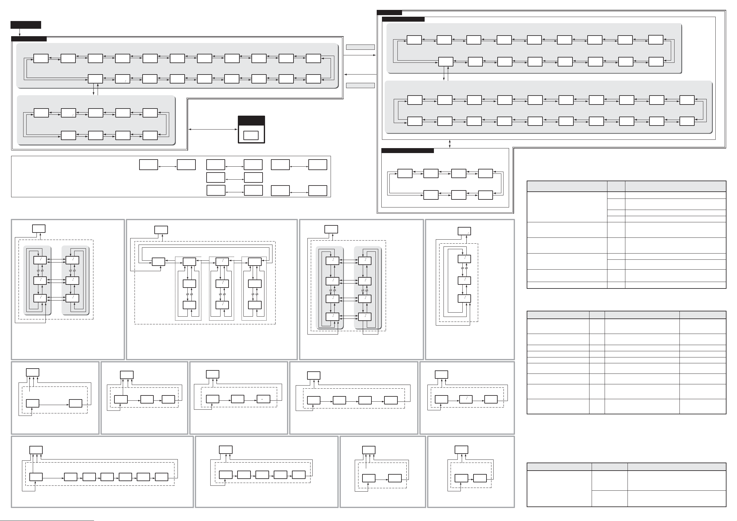
Pro Level
Basic Level
Power ON
State Transition
Basic Level
Pro Level
Protect
Setting Mode
Measurement Mode
Setting Mode
Operation Setting Mode
Communication Setting Mode
■
Power ON
Measurement Mode
Basic Level
Pro Level
M+SM+S
*Example of 3-phase 3-wire
When the setting is 1-phase 2-wire, the current 2, 3 and the voltage 2, 3 are not displayed.
When the setting is 1-phase 3-wire, the 2nd. display of current and voltage changes. (e.g.
Total integral
power
Active power
0.000 0.0 0.000 0.000 0.000 0.0 0.0
*1 *1 *1 *1
Pulse input
count
consumption
M+SM+S
kw kwh a-r a-5 a-t v-r5 v-st
S
Electric power
consumption rate
cnt
0
0.000
Hwh p
S
*4*4 *4
Product
information
SSS S
c1flk
Current 1 Current 2 Current 3
M+S
S
SS
M+S
S
v2.0
M+S
M+S
S
*3*2 *3 *3
Pro Level
M+S
U
M
Pulse input
ON time
M+S
00-00
h-on
S
Simple
temperature
C
0.0
temp
M+S M+S M+S
Time
Total integral
regenerated
power consumption
Total integral
total reactive
power consumption
The measurement mode can display a past measured
value. (*1 to *4)
While it is in condition to display a past measured value,
display the date and time and a measured value in turn.
Please refer to a right figure.
Active power
*1
・Example of active power
・Alternately displays the time when maximum and minimum values were
recorded, and the maximum and minimum values, for each day.
・Reactive power displays only the maximum and minimum values of the
current day.
*5
・When selecting others than “none”, sequentially set
VT primary side voltage and VT secondary voltage.
*10
0.000
kw
U
M
Maximum value
UU
02 25
00-00
M+U
U
03 04
00-00
M+U
U
03 05
00-00
M+U
VT setting
none
03.v.rg
U
M
at “none” :O
VT
primary side
voltage value
At selection
excluding “none”
none
03.v.rg
Output terminal 1
function setting
p.out
50.o1
U
M
At selection
excluding “alarm”
p.out
At “alarm”:O
50.o1
・Example of output terminal 1 function setting
・When selecting
“alarm”, set each alarm to ON/OFF.
M+S
S
M+S
S
M+S
S
:O
Minimum value
02 25
00-00
M+U
U
03 04
00-00
M+U
U
03 05
00-00
M+U
VT
secondary side
voltage value
:O
110
v.rg2
Active power
alarm output
O
off
p.al
Regenerated
power alarm
output
off
r.al
Simple
measurement
*6
U
08.smp
・When the simple measurement is ON, sequentially
set the fixed voltage value and fixed power factor
value.
Volt age
Current
alarm output
alarm output
O
O
off
a.al
a-s→a-n)
M+S
S
M+S
Pulse conversion
value 2
S
Moving average
current 1
M+S
0.000 0.000 0.000
S
M+S
ma-r ma-s
Pulse conversion
value 1
S
M+S
S
S
M+S
Moving average
current 2
Charge
conversion value
jpym3-1m3-203 05
Moving average
current 3
M+S
S
CO
exchanged
2
value
S
0.0000.0000.0000.00017-15 55.0
M+S
ma-t
co2
Voltage 1 Voltage 2
M+S
S
Frequency
S
M+S
M+S
S
hz
Please refer to figure *1 to *4 for the transition that is in an internal state of *1 to *4.
Total integral
leading reactive
power consumption
M+S
0.0
-kwh
S
0.0
kvh.a
*1
*2
・On monthly display, the 1st. display alternately displays Year-Month of when the integral power consumption
was recorded, and the value of integral power consumption. The 2nd. display alternately displays “how many
months ago” and a unit.
・On daily display, the 1st. display alternately displays Month/Day of when the integral power consumption was
recorded, and the value of integral power consumption. The 2nd. display alternately displays “how many days
ago” and a unit.
・On hourly display, the 1st. display alternately displays Date-Hour of when the integral power consumption was
recorded, and the integral power consumption. The 2nd. display alternately displays “how many hours ago”
and a unit.
off
08.smp
M
at OFF : O
ON時:O
on
O
off
v.al
Total integral
lagging reactive
power consumption
Month/Day
Hour-Minute
Total integral
power consumption
10-digit display
M+S
Fixed voltage
value.
110.0
vlt pf
Power factor
alarm output
off
pf.a
0.0
kvh.d
S
0.0
kvh.g
Alternate display
(1.5 sec auto)
Total integral
power consumption
0.0
kwh
U
M
00000
00000
S
Fixed power
factor value.
O
Reactive power
alarm output
O
off
q.al
M+S
1.00
O
O+M
(3 sec min.)
MAX/MIN
*2
Year-Month
Active power
Month/Day
Day-Hour
Monthly integral
power consumption
for past 13 months
M+U
M+U
M+U
M+S
10-03
0 m
SSS
U
U
09-02
-13 m
U
10-02
- 1 m
Charge
*7
conversion setting
10.000
U
Rate setting
10.000
・Sequentially set the rate and price unit.
・For the price unit, after choosing from options, user can
change it to any unit.
*11
・Example of active power alarm output
・Sequentially set upper/lower thresholds, hysteresis and OFF-/ON-delay.
・The second displays of upper/lower thresholds and hysteresis switch to operating values
calculated from the threshold after 1.5 sec.
Months ago
Days ago
Hours ago
Daily integral
power consumption
for past 8 days
03 05
M+U
02 25
- 8 d
M+U
03 04
- 1 d
M+U
11.chg
M
O O
rate
Active power
alarm output
U
Upper
threshold
Alternate display
(1.5 sec auto)
Alternate display
(1.5 sec auto)
Alternate display
(1.5 sec auto)
0 d
U
U
U
Price unit setting
(Selection)
80.0
52.p.al
M
O
80.0
ov.th
M+S
jpy
Lower
threshold
Protect
Setting Mode
Protect setting
0
prtct
unit
Integral power
Integral power
Integral power
M+U
M+U
M+U
0.0
un.th
*3
consumption
Unit
consumption
Unit
*4
consumption
Unit
Hourly integral
power consumption
for past 25 hours
5-17
0 h
U
U
4-16
-25 h
U
5-16
- 1 h
Price unit setting
(Arbitrariness)
jpy
unit
Hysteresis OFF-delay ON-delay
O
5.0
al.hys
O
O
Reactive power
S
0.000prolv
kvar
*1 *1
Month/Day
Hour-Minute
Month/Day
Days ago
O
3.0
of.dly
Setting Mode
Operation Setting Mode
Basic Level
M
(3 sec min.)
0.000
a-r
M
Measurement stop
Measurement start
M
(3 sec min.)
Pro Level
Communication Setting Mode
M+SM+SM+S
M+S
S
S
Alternate display
(1.5 sec auto)
Alternate display
(1.5 sec auto)
Voltage 3
Power factor
1.00
Current
MAX/MIN/AVE
Electric power
consumption rate
*3
0.0
v-tr
pf
S
M+SM+SM+S
Unit
Current
U
Maximum value Minimum value
UU
M+S
03 05
00-00
M+U
U
02 25
00-00
M+U
U
03 04
00-00
M+U
U
03 05
00-00
M+U
・Alternately displays the time when maximum and minimum values were
recorded, and the maximum and minimum values, for each day.
・Moving average current displays only the maximum value.
minimum value is non-compliant. (display "-"mark)
Pulse conversion 1
*8
setting
c-1.d
12.cv1
U
M
Pulse conversion
target 1
c-1.d
・Example of pulse conversion 1 setting
・Sequentially set the pulse conversion target, factor, decimal point position
and display unit.
O
0.0
on.dly
Factor setting 1
O O O
targ
0001
slp
-- --
-----
S
M+U
02 25
00-00
M+U
03 04
00-00
M+U
03 05
00-00
M+U
Decimal point
position setting 1
0000
Automatic rotation
U
Automatic rotation
transition time.
U
U
U
dp
off
61.rtt
M
atOFF:O
off
61.rtt
atON:O
Display unit
setting 1
m3-1
Transition time
M+S
S
M+S
S
M+S
S
*12
・When the automatic rotation is ON, set the
Applicable
circuit type
M+SM+S
3p3w
00.typ
Event input
setting
M+S
p.csp
30.ei5
Simple
temperature setting
S
c
65.d-u
*13
Protocol
select
compf
80.psl
SS S
*9
O
unit
O
3
rtim
Dedicated
CT type
100a
S
01.c.rg
Pro Level
prolv
U
S S
M+S
S
M+S
Rated primary
current value
Moving average
time Setting
S
5
02.5ct
120
16.avt
S
none
03.v.rg 04.cut
*5 *6
Initialization
S
5et
M+S M+S
15.ini
VT setting
M+S
Current low-cut
value
M+S
S
M+S
0.6
Time setting
S
2010
14.tim
*9 *8 *8
M+S
S
M+S
Pulse output
unit
100
05.pl5
Pulse conversion 2
setting
S
c-2.d
13.cv2
M+S
S
M+S
Display refresh
period
06.ref
Pulse conversion 1
setting
S
c-1.d
12.cv1
1.0
M+S
S
M+S
Averaging times
07.avg
Charge
conversion setting
S
10.000
*7
8
11.chg
M+S
S
S
M+S
Simple
measurement
off
08.5mp
conversion
CO
2
factor
0.387
10.co2
M
Event input 1
NPN/PNP input
mode setting
M+S
pnp
Incorrect voltage
wiring detection
S
31.pn1
on
64.v-e
S
M+S
O
Unit No.
1
8 lu.no
Time to wait
for sending
SSS
20
86.5dw
M+SM+SM+S
*4
・
Example of electric power consumption rate
・The 1st. display alternately displays Month/Day
of when electric power consumption rate was recorded, and the electric power consumption rate.
The 2nd. display alternately displays
days ago
M+S
S
M+S
Baud rate
9.6k
82.bp5
Vertical parity
even
85.prt
Electric power
consumption rate
0.000
U
02 25
M+U
03 03
M+U
03 04
M+U
” and a unit.
Event input 2
NPN/PNP input
mode setting
Display lighting
time
S
M+S
Hwh p
M
U
- 8 d
U
- 2 d
U
- 1 d
pnp
32.pn2
0
63.dsp
Data bit
length
Stop bit
length
M+S
S
M+S
83.len
84.5bt
S
7
2
“how many
Event input 1
N-O/N-C input
mode setting
n-o
33.in1
S
Measurement parameter
display selection
on
62.d.sl
M+S
S
Event input 2
M+S
S
N-O/N-C input
mode setting
Automatic rotation
setting
*12
n-o
34.in2
off
61.rtt
M+S
S
M+S
Measurement
start time
00-00
Integral power
consumption
saving selection
S
35.5tc
-w
60.i.sl
M+S
S
M+S
Measurement
end time
24-00
Reactive power
alarm output
S
36.etc
80.0
57.q.al
M+S
S
M+S
Output terminal 1
function setting
p.out
*10
Power factor
alarm output
S
56.pf.a
50.o1
100
M+S
S
M+S
Active power
alarm output
*11
Voltage alarm
output
S
80.0
52.p.al
110.0
55.v.al
Please refer to figure *5 to *13 for the transition that is in an internal state of *5 to *13.
■Unit to save each measured value
The KM50 model has a function to save various measured values in EEPROM every five minutes, every day
or every month. The list of measured values and saving units is shown below:
Measured value
Integral
power consumption
Active power, current, voltage and
power factor
(Maximum and minimum values)
Moving average current
(Only the maximum values)
Pulse input count
Electric power consumption rate
Pulse input ON time
Integral regenerated power consumption
Integral reactive power consumption
Total pulse count inputs
Saving
period
Save two days’ measured values every 5 min.
5 min.
Save 25 hours’ hourly values which are converted from
1 hour
measured values saved every 5 min.
Save 8 days’ values measured between 00:00 and 24:00.
1 day
Save 13 months’ values measured for a month.
1 month
Save 8 days’ values measured between 00:00 and 24:00.
1 day
(After saving, measured values are reset.)*
ー
Save the current maximum values of the moving average
time.
(The moving average current with a product Ver.3.0.)
Save two days’ measured values every 5 min.
5 min.
Save 8 days’ values measured between 00:00 and 24:00.
1 day
Save two days’ measured values every 5 min.
5 min.
Save only items selected in the setting.
Overwrite save the measured value every 5 min.
5 min.
Note 1. At the time of power failure, the clock time data is retained for 7 days.
Note 2. User can check the data every 5 min. only through communication.
■Error indication
Description of error
KM50 internal clock time has not
been set.
Built-in memory error
(RAM error) (*1)
Display
e-t1
Indicates error at startup and “STOP” is
turned ON. Measurement stops and
operation disabled during error indication.
e-m1
Measurement stop, operation disabled
EEPROM error (*1) e-m2 Measurement stop, operation disabled Hardware repair (*2)
Operation
EEPROM data failed (*1) e-m3 Measurement stop, operation disabled Hardware repair (*2)
e-m4 Measurement stop, operation disabled Hardware repair (*2)
e-s1 Displays error and measurement value
alternately and continues measurement.
alternately and continues measurement.
alternately and continues measurement.
alternately and continues measurement.
Time setting
2010
14.tim
U
M
Year Month/Day Hour/Minute
O
2010
14.tim
・Sequentially set the year, month/day and hour/minute.
01 01
14.tim
O
00-00
14.tim
O
Calibration value error (*1)
Excessive voltage input (*3)
Excessive current input (*3) e-s2 Displays error and measurement value
Frequency input error (*3) e-s3 Displays error and measurement value
Incorrect wiring detection (*4) e-s4 Displays error and measurement value
*1 When any of e-m1 – m4 errors occurs, all outputs stop and any key operation is not accepted.
*2 Consult your OMRON representative.
*3 An error will occur when the input of voltage exceeds 110% of the rated value, current exceeds 120% of
the rated value, frequency is below 45 Hz or more than 65 Hz.
*13
Simple
temperature setting
c
65.d-u
U
M
Temperature
Temperature
unit
・Sequentially set the temperature unit and
temperature correction value.
correction
value
OO
c
65.d-u
0.0
t.ad
When the voltage input is 20 V or less, frequency error isn’t displayed.
When VT is set, the set value of secondary voltage becomes the rated voltage.
*4 For e-54 error, only when the incorrect voltage wiring detection is set to ON, the error is displayed.
■Troubleshooting
Phenomenon Description Point to be checked
Voltage and current are measured
but electric power is not correctly
measured.
Has CT (Current
Transformer) been
correctly wired
(not in reverse)?
Is the voltage
phase sequence
correct?
If negative electric power is measured, it might be
all the CTs have been mounted oppositely. On the
other hand, if the measured value is nearly 0, it might
be one of the CTs has been mounted oppositely.
If the voltage phase sequence is not correct,
electric power cannot be measured correctly.
Perform correct wiring.
Regenerated
power alarm output
M+S
80.0
*11
Current alarm
output
S
*11*11*11*11
53.r.al
110.0
54.a.al
S
M+S
Remarks
Restoration method
Time setting
Hardware repair (*2)
Restore the input signal
within to the rated range.
Restore the input signal
within to the rated range.
Restore the input signal
(voltage) within to the
rated range.
Correct the input signal
(voltage) wiring in phase
sequence.
S
M+S
 Loading...