

Page 1
1
Overview
2
Procedure
Insulation Resistance
Monitoring Device
User's Manual
K7GE-MG
3
Installation and
Wiring
4
Functions Related
to Measurement
5
Using Setting
Parameters
6
Remote Monitoring
Troubleshooting
A
Appendices
I
Index
N224-E1-01
Page 2

NOTE
All rights reserved. No part of this publication may be reproduced, stored in a retrieval system, or transmitted, in
any form, or by any means, mechanical, electronic, photocopying, recording, or otherwise, without the prior
written permission of OMRON.
No patent liability is assumed with respect to the use of the information contained herein. Moreover, because
OMRON is constantly striving to improve its high-quality products, the information contained in this manual is
subject to change without notice. Every precaution has been taken in the preparation of this manual. Nevertheless, OMRON assumes no responsibility for errors or omissions. Neither is any liability assumed for damages
resulting from the use of the information contained in this publication.
Trademarks
• Microsoft, Windows is either registered trademarks or trademarks of Microsoft Corporation in the United States
and other countries.
• Megger is a registered trademark or trademark of Megger Group Limited.
• Modbus is a registered trademark or trademark of Schneider Electric USA, Inc. in Japan, the United States or
other countries.
Other company names and product names in this document are the trademarks or registered trademarks of their
respective companies.
Copyrights
Microsoft product screen shots reprinted with permission from Microsoft Corporation.
Page 3

Preface
Thank you for purchasing a K7GE-MG Insulation Resistance Monitoring Device. This manual describes
how to use the K7GE-MG.
Read this manual thoroughly and be sure you understand it before attempting to use the K7GE-MG
correctly according to the information provided. Keep this manual in a safe place for easy reference.
A PDF version of this manual can be downloaded from the OMRON website. (http://www.omron.com)
In this manual, "K7GE-MG" refers to the K7GE-MG with its Main Unit connected to the Probe Units.
It is assumed that the load that the K7GE-MG measures is a motor. Before you use it for other
equipment such as a heater or transformer, carefully study the operating specifications of the
K7GE-MG.
Preface
Insulation Resistance Monitoring Device User’s Manual (N224)
1
Page 4

Terms and Conditions Agreement
Terms and Conditions Agreement
Warranty, Limitations of Liability
Warranties
Exclusive Warranty
Omron’s exclusive warranty is that the Products will be free from defects in materials and
workmanship for a period of twelve months from the date of sale by Omron (or such other period
expressed in writing by Omron). Omron disclaims all other warranties, express or implied.
Limitations
OMRON MAKES NO WARRANTY OR REPRESENTATION, EXPRESS OR IMPLIED, ABOUT
NON-INFRINGEMENT, MERCHANTABILITY OR FITNESS FOR A PARTICULAR PURPOSE OF
THE PRODUCTS. BUYER ACKNOWLEDGES THAT IT ALONE HAS DETERMINED THAT THE
PRODUCTS WILL SUITABLY MEET THE REQUIREMENTS OF THEIR INTENDED USE.
Omron further disclaims all warranties and responsibility of any type for claims or expenses based
on infringement by the Products or otherwise of any intellectual property right.
Buyer Remedy
Omron’s sole obligation hereunder shall be, at Omron’s election, to (i) replace (in the form originally
shipped with Buyer responsible for labor charges for removal or replacement thereof) the
non-complying Product, (ii) repair the non-complying Product, or (iii) repay or credit Buyer an
amount equal to the purchase price of the non-complying Product; provided that in no event shall
Omron be responsible for warranty, repair, indemnity or any other claims or expenses regarding the
Products unless Omron’s analysis confirms that the Products were properly handled, stored,
installed and maintained and not subject to contamination, abuse, misuse or inappropriate
modification. Return of any Products by Buyer must be approved in writing by Omron before
shipment. Omron Companies shall not be liable for the suitability or unsuitability or the results from
the use of Products in combination with any electrical or electronic components, circuits, system
assemblies or any other materials or substances or environments. Any advice, recommendations or
information given orally or in writing, are not to be construed as an amendment or addition to the
above warranty.
See http://www.omron.com/global/ or contact your Omron representative for published information.
Limitation on Liability; Etc
OMRON COMPANIES SHALL NOT BE LIABLE FOR SPECIAL, INDIRECT, INCIDENTAL, OR
CONSEQUENTIAL DAMAGES, LOSS OF PROFITS OR PRODUCTION OR COMMERCIAL LOSS IN
ANY WAY CONNECTED WITH THE PRODUCTS, WHETHER SUCH CLAIM IS BASED IN
CONTRACT, WARRANTY, NEGLIGENCE OR STRICT LIABILITY.
Further, in no event shall liability of Omron Companies exceed the individual price of the Product on
which liability is asserted.
2
Insulation Resistance Monitoring Device User’s Manual (N224)
Page 5
Application Considerations
Suitability of Use
Omron Companies shall not be responsible for conformity with any standards, codes or regulations
which apply to the combination of the Product in the Buyer’s application or use of the Product. At
Buyer’s request, Omron will provide applicable third party certification documents identifying ratings
and limitations of use which apply to the Product. This information by itself is not sufficient for a
complete determination of the suitability of the Product in combination with the end product, machine,
system, or other application or use. Buyer shall be solely responsible for determining appropriateness
of the particular Product with respect to Buyer’s application, product or system. Buyer shall take
application responsibility in all cases.
NEVER USE THE PRODUCT FOR AN APPLICATION INVOLVING SERIOUS RISK TO LIFE OR
PROPERTY OR IN LARGE QUANTITIES WITHOUT ENSURING THAT THE SYSTEM AS A WHOLE
HAS BEEN DESIGNED TO ADDRESS THE RISKS, AND THAT THE OMRON PRODUCT(S) IS
PROPERLY RATED AND INSTALLED FOR THE INTENDED USE WITHIN THE OVERALL
EQUIPMENT OR SYSTEM.
Terms and Conditions Agreement
Programmable Products
Omron Companies shall not be responsible for the user’s programming of a programmable Product, or
any consequence thereof.
Disclaimers
Performance Data
Data presented in Omron Company websites, catalogs and other materials is provided as a guide for
the user in determining suitability and does not constitute a warranty. It may represent the result of
Omron’s test conditions, and the user must correlate it to actual application requirements. Actual
performance is subject to the Omron’s Warranty and Limitations of Liability.
Change in Specifications
Product specifications and accessories may be changed at any time based on improvements and other
reasons. It is our practice to change part numbers when published ratings or features are changed, or
when significant construction changes are made. However, some specifications of the Product may be
changed without any notice. When in doubt, special part numbers may be assigned to fix or establish
key specifications for your application. Please consult with your Omron’s representative at any time to
confirm actual specifications of purchased Product.
Errors and Omissions
Information presented by Omron Companies has been checked and is believed to be accurate;
however, no responsibility is assumed for clerical, typographical or proofreading errors or omissions.
Insulation Resistance Monitoring Device User’s Manual (N224)
3
Page 6
Safety Precautions
Safety Precautions
Definition of Precautionary Information
The following notation is used in this manual to provide precautions required to ensure safe usage of
the K7GE-MG Insulation Resistance Monitoring Device.
The safety precautions that are provided are extremely important to safety. Always read and heed the
information provided in all safety precautions.
The following notation is used.
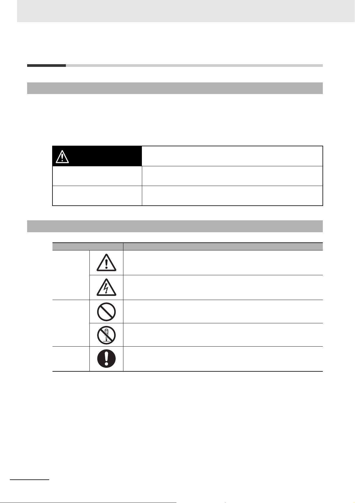
CAUTION
Indicates a potentially hazardous situation which, if not avoided,
may result in minor or moderate injury, or in property damage.
Symbols
Precautions for
Safe Use
Precautions for
Correct Use
Symbol Meaning
Caution
Prohibition
Mandatory
Caution
Precautions on what to do and what not to do to ensure safe usage
of the product.
Precautions on what to do and what not to do to ensure proper
operation and performance.
• General Caution
Indicates non-specific general cautions, warnings, and dangers.
• Electrical Shock Caution
Indicates possibility of electric shock under specific conditions.
• General Prohibition
Indicates non-specific general prohibitions.
• Disassembly Prohibition
Indicates prohibitions when there is a possibility of injury, such as from electric
shock, as the result of disassembly.
• General Caution
Indicates non-specific general cautions, warnings, and dangers.
4
Insulation Resistance Monitoring Device User’s Manual (N224)
Page 7
Safety Precautions
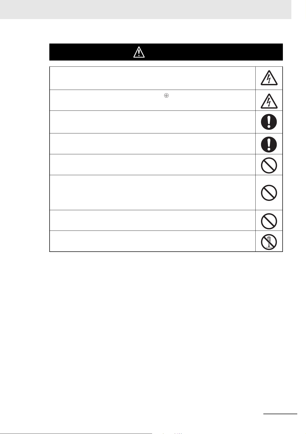
CAUTION
Minor injury due to electric shock may occasionally occur. Do not touch the Product
except for any buttons (keys) while power is being supplied.
Always connect the protective earthing terminal ( ) to a ground.
Use AWG 16 for the protective conductor.
If the wiring material is inserted in a shallow position, it may cause property damage due
to ignition. When wiring, make sure that the wiring material is properly inserted all the
way into the terminal block.
If used the Product with incorrect wiring, it may cause property damage due to ignition.
Make sure the cable is connected properly when the power supply is turned ON.
Minor electric shock, fire, or malfunction may occasionally occur. Do not allow metal
objects, conductors, or cuttings from installation work to enter the Product.
Perform periodic inspection to the Product. A malfunction in the Product may
occasionally prevent monitoring impossible or alarm outputs, resulting in property
damage to connected equipment or devices. To maintain safety in the event of
malfunction of the Product, take appropriate safety measures, such as installing a
monitoring device on a separate line.
Minor injury due to explosion may occasionally occur.
Do not use the Product where subject to flammable or explosive gas.
Minor electric shock, fire, or malfunction may occasionally occur.
Do not disassemble, modify, or repair the Product or touch the interior of the Product.
Insulation Resistance Monitoring Device User’s Manual (N224)
5
Page 8

Precautions for Safe Use
Precautions for Safe Use
(1) Do not use or store the Product in the following locations:
• Outdoor or locations subject to direct sunlight
• Locations subject to rain and wind damage
• Locations subject to excessive vibration or shock
• Locations subject to rapid temperature changes
• Locations prone to icing and dew condensation
• Locations subject to water or oil
• Locations subject to dust or corrosive gases (particularly sulfurizing gases, ammonia, etc.)
• Locations subject to influence of static electricity and noise
• Locations subject to bugs and small animals
(2) A switch or circuit breaker should be provided close to this Unit. The switch or circuit breaker
should be within easy reach of the operator, and must be marked as a disconnecting means for this
Unit.
(3) Mount the Product in the correct direction for installation.
(4) Be sure to use power terminals carefully, because power supply terminals have hazardous voltage.
(5) Use the wire given in this manual.
(6) Use the power supply voltage within the range of the specifications and rated values. Use the input
voltage within the range of the specifications and rated values.
(7) Make sure the crimp terminals for wiring are of the specified size.
(8) Do not connect anything to terminals that are not being used.
(9) Confirm the wiring the input and output terminals correctly before power is supplied.
(10) The terminal block may be damaged if you insert a flat-blade screwdriver in the release hole with
excessive force. When inserting a flat-blade screwdriver into the release holes, operate with a
force of 15•N or less.
(11) K7GE-MG may be subject to radio disturbances. Do not install the Product near equipment that
generates high frequencies or surges.
(12) The maximum terminal temperature is 80°C. Use wires with a heat resistance of 80°C min to wire
the terminals.
(13) Make sure the LCD and the LEDs for output indicators operate correctly. Depending on the
operating environment, the Product parts may deteriorate faster than expected, causing the
indicators to fail.
(14) Use the cable within the length that is rated in the specification requirements for the wiring between
the sensor and the Product. As for the requirements on the cable distance, refer to 3-6 Wiring the
Communications Cable on page 3-13.
(15) In order to prevent inductive noise, wire the lines connected to the Product separately from power
lines carrying high voltages or currents. Also, do not wire in parallel with or on the same cables as
power lines. Other measures for reducing noise are to separate from ducts including noisy lines.
(16) Do not continue to use the Product if the front surface peels.
(17) The alarm output function is a function for the output of an alarm when the set threshold value is
below. Do not use this function for control, etc.
(18) Use this Product inside the control panel to prevent external noise.
(19) When discarding the Product, properly dispose of it as industrial waste.
(20) Never touch the charging terminal of the load while the K7GE-MG is in measurement operation.
(21) K7GE-MG cannot be used for legal inspection. Be sure to use a periodically calibrated measuring
instrument for legal inspection.
(22) When wiring, wire by enough length.
6
Insulation Resistance Monitoring Device User’s Manual (N224)
Page 9

Precautions for Safe Use
(23) Check terminal polarity when wiring and wire all connections correctly. Do not wire the input and
output terminals incorrectly.
(24) K7GE-MG provides 50 VDC of Megger voltage. Do not use on equipment that may be damaged by
this voltage.
(25) Use and store the Product in a location where the ambient temperature and humidity are within the
specified ranges. If applicable, provide forced cooling.
(26) Please read and understand this manual before using K7GE-MG.
Insulation Resistance Monitoring Device User’s Manual (N224)
7
Page 10

Precaution for Correct Use
Precaution for Correct Use
Observe the following operating methods to prevent failure and malfunction.
(1) During periodic inspection, installation of an additional sensor, or adjustment of sensor position,
use the Product after ensuring that correct operation can be performed.
(2) When mounting K7GE-MG on a DIN Track, follow the installation method described in Mounting to
DIN Track on page 3-4 to install it correctly.
(3) Confirm that wire does not stick up after wiring of stranded cable.
(4) In case of crossover wiring, install these by 10 A per 1 terminal because when Products are
connected more than one in parallel, quite many electric currents to be called off.
(5) The terminal block may be damaged if specialized tool is not used. Use a recommended flat-blade
screwdriver to inserted into a release hole on the terminal block.
(6) This Product is designed for use by qualified personnel with a knowledge of electrical systems.
Read this manual carefully before using the Product.
(7) Use the power supply voltage, input power, and other power supplies and transformers with
suitable capacities and rated outputs.
(8) Use a power supply that will reach the rated voltage within 1 second after the power is turned ON.
(9) Do not install the Product close contact with the heating element.
(10) Do not install the Product near equipment that generates high frequencies or surges.
(11) Install the Product so that the load doesn't span the Product body.
(12) If an error occurs during K7GE-MG operation, stop operation immediately and make suitable
corrections such as replacement.
(13) Do not use K7GE-MG for safety devices or applications that could result in loss of life.
(14) Make sure to connect Main Unit and Probe Units before use.
(15) Make sure that the number of additional Probe Units is within the specified range.
(16) Be sure to install a magnetic contactor, etc. between the power supply and the load, and wire
K7GE-MG on the secondary side of it.
(17) Do not turn ON power to the load while K7GE-MG is measuring.
(18) Set the "Motor stop waiting time" setting value to at least the time from when the contactor is turned
off until the load completely stops.
(19) If you accidentally drop K7GE-MG, the inside of the Product may be damaged, so do not use it.
(20) Do not wire anything to the release holes.
(21) Do not tilt or twist a flat-blade screwdriver while it is inserted into a release hole on the terminal
block. The terminal block may be damaged.
(22) Insert a flat-blade screwdriver into the release holes at an angle. The terminal block may be
damaged if you insert the screwdriver straight in.
(23) Do not allow the flat-blade screwdriver to fall out while it is inserted into a release hole.
(24) Do not bend a wire past its natural bending radius or pull on it with excessive force. Doing so may
cause the wire disconnection.
(25) Do not insert more than one wire into each terminal insertion hole.
(26) Do not use any liquids such as paint thinner, similar solvents or alcohol to clean the Product. Clean
it with a soft, dry cloth.
8
Insulation Resistance Monitoring Device User’s Manual (N224)
Page 11
Regulations and Standards
P1
P2
N
P3
E
E
L1
L2
N
L3
PE
PEN
P1
P2
P3
EE
L1
L2
EE
L1
L2
EE
N
Conformance to Safety Standards
• For wiring from the Probe Unit to the load, use a Class CC, Class J, or Class T fuse with a rated
current of 7A or less.
• The protection provided by the device may be impaired if the device is used in a manner that is
not specified by the manufacturer.
• To use the Product, install it as an embedded device within a control panel.
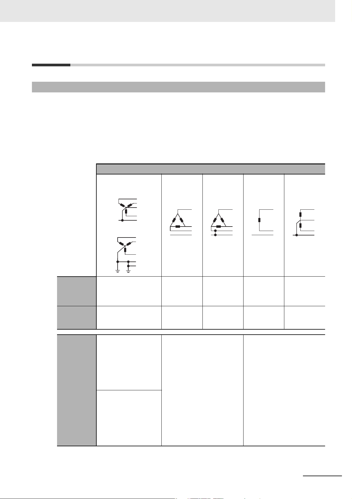
• The table below shows the nominal voltage and measurement circuit connections available for
each measurement category in the Main Power Supply System Configurations. Do not use the
device under conditions that exceed this category and conditions.
Main Power Supply System Configurations
3-phase, 4-wire type
(neutral point grounding)
TT
3-phase,
3-wire type
(no grounding)
3-phase,
3-wire type
(single-phase
grounding)
P1
Regulations and Standards
Single-phase,
2-wire type
AC or DC
Single-phase
(split phase),
2-wire type
AC or DC
TN-C-S
CAT III Phase voltage/line
voltage
277 V/480 V
Line voltage
300 V
P2
P3
EE
Line voltage
300 V
Line voltage
240 V
Phase
voltage/line
voltage
240 V/480 V
CAT II 347 V/600 V in addition to
the above
Connection
to
measurement
circuit
TT:
Connect E in the diagram
above to the No. 7
terminal (PE) of the
K7GE-MGM.
Connect P1 and P2 to the
480 V in
addition to the
above
480 V in
addition to the
above
Connect E in the diagram above
to the No. 7 terminal (PE) of the
K7GE-MGM.
Connect P1 and P2 to the No. 1
and No. 3 terminals of the
K7GE-MG1.
480 V in
addition to the
Same as
above
above
Connect E in the diagram above
to the No. 7 terminal (PE) of the
K7GE-MGM.
Connect L1 and L2 to the No. 1
and No. 3 terminals of the
K7GE-MG1.
No. 1 and No. 3 terminals
of the K7GE-MG1.
TN-C-S:
Connect PE in the
diagram above to the No.
7 terminal (PE) of the
K7GE-MGM.
Connect L1 and L2 to the
No. 1 and No. 3 terminals
of the K7GE-MG1.
Insulation Resistance Monitoring Device User’s Manual (N224)
9
Page 12
Regulations and Standards
Fixed
equipment
Distribution board
CAT IV
CAT III
CAT IICAT I
Internal wiring
Service
entry wire
Power
outlet
Measurement Category
The measurement category classifies the places and equipment which you can connect to the
measurement terminals, as prescribed in EN/IEC 61010-2-030. Each category is as follows.
CAT I: Equipment to connect to circuits where
measures are taken to limit transient
overvoltages to low levels
CAT II: Energy-consuming equipment with an
energy supply from fixed wiring equipment
(such as a power outlet)
CAT III: Equipment in fixed wiring equipment that
particularly demands equipment reliability
and effectiveness
CAT IV: Equipment to use at the electrical service
entry
Conformance to EN/IEC Standards
This is a class A product. In residential areas it may cause radio interference, in which case the user
may be required to take adequate measures to reduce interference.
10
Insulation Resistance Monitoring Device User’s Manual (N224)
Page 13
Terminology
Ter m Abbreviation Description
CompoWay/F - CompoWay/F is OMRON's standard communications format for
FINS (Factory Interface
Network Service)
Modbus RTU - This is a standard communications control method that conforms to
Channels CH The units of the insulation measurement loop for the Insulation
Power ON reset - A reset process that runs when the power turns ON.
Terminology
general serial communications. This format uses a standard frame
format as well as the well-established FINS commands used for
OMRON's PLCs. Therefore, it can simplify communications
between components and the host.
FINS The FINS protocol provides message communications between
controllers in OMRON FA networks.
Modicon Inc.'s RTU-mode Modbus Protocol (PI-MBUS-300 Rev. J).
Resistance Monitoring Device.
Protective earthing PE The protective earth to connect to the housing of a device to bring
the housing to the same potential as the ground and allow ground
fault currents to flow to ground.
K7GE-MG - "K7GE-MG" refers to the K7GE-MG with its Main Unit connected to
the Probe Units.
Megohmmeter - An instrument that measures the insulation resistance of electrical
products and indoor wiring, also called an insulation resistance
meter.
Megger voltage - The voltage that the device applies to measure the insulation
resistance. The K7GE-MG applies 50 VDC.
Megger method - A method to measure resistance values by connecting a measuring
circuit between a ground-insulated charged section that is
connected to the power line and a non-charged section such as a
grounded motor frame.
Parasitic capacitance - The capacitance that exists between the charging terminal of the
load and the terminal such as between PE. Also called stray
capacitance.
Insulation Resistance Monitoring Device User’s Manual (N224)
11
Page 14
Manual Structure
A
Manual Structure
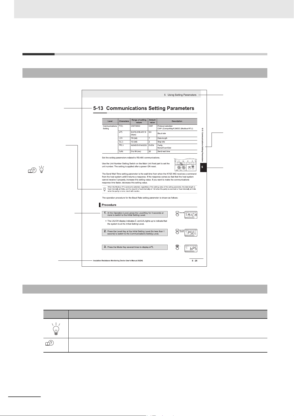
Page Structure
Level 2 heading
Special information
Icons indicate precautions,
additional information, or
reference information.
Level 1 heading
Level 2 heading
Gives the current
headings.
Page tab
Gives the number
of the main section.
step in a procedure
Indicates a procedure.
Manual name
Icons
Special information in this manual is classified as follows:
Icon Meaning
No. **
Additional information to read as required.
This information is provided to increase understanding or give hints on operation.
This indicates the position in Section 2 Procedure that provides more detailed information about
trouble and countermeasures.
12
Insulation Resistance Monitoring Device User’s Manual (N224)
Page 15
Revision History
N224-E1-01
Revision code
A manual revision code appears as a suffix to the catalog number on the front cover of the manual.
Revision code Date Revised content
01 January 2021 Original production
Revision History
Insulation Resistance Monitoring Device User’s Manual (N224)
13
Page 16

Revision History
14
Insulation Resistance Monitoring Device User’s Manual (N224)
Page 17
1
3
4
5
6
A
I
4
5
6
7
A
I
Overview
Installation and Wiring
2
Procedure
Functions Related to Measurement
Using Setting Parameters
Remote Monitoring
Troubleshooting
Appendices
Index
3
7
1
2
Sections in this Manual
Insulation Resistance Monitoring Device User’s Manual (N224)
15
Page 18

CONTENTS
Preface ...................................................................................................................... 1
Terms and Conditions Agreement .......................................................................... 2
Warranty, Limitations of Liability .................................................................................................................. 2
Application Considerations .......................................................................................................................... 3
Disclaimers .................................................................................................................................................. 3
Precautions...............................................................................................................4
Definition of Precautionary Information........................................................................................................ 4
Symbols....................................................................................................................................................... 4
Precautions for Safe Use......................................................................................... 6
Precaution for Correct Use......................................................................................8
Regulations and Standards.....................................................................................9
Conformance to Safety Standards............................................................................................................... 9
Conformance to EN/IEC Standards...........................................................................................................10
Terminology ............................................................................................................ 11
Manual Structure .................................................................................................... 12
Page Structure........................................................................................................................................... 12
Icons .......................................................................................................................................................... 12
Revision History .....................................................................................................13
Sections in this Manual .........................................................................................15
CONTENTS..............................................................................................................16
Section 1 Overview
1-1 Overview................................................................................................................................. 1-2
1-2 Features.................................................................................................................................. 1-3
1-3 Model Number Legend..........................................................................................................1-6
1-4 Insulation Resistance Measurement and Monitoring System........................................... 1-7
1-5 Nomenclature and Functions ............................................................................................... 1-8
1-6 Internal Block Diagram .......................................................................................................1-14
1-7 System Configurations ....................................................................................................... 1-16
1-8 Safety Precautions .............................................................................................................. 1-18
Section 2 Procedure
2-1 Procedure............................................................................................................................... 2-2
(1) Advance Preparation........................................................................................................................... 2-2
(2) Installation and Wiring.........................................................................................................................2-3
(3) Initial Setting........................................................................................................................................2-5
(4) Test Operation with Manual Measurement ......................................................................................... 2-7
(5) Starting Operation ............................................................................................................................... 2-8
Troubleshooting......................................................................................................................................2-10
16
Insulation Resistance Monitoring Device User’s Manual (N224)
Page 19

Section 3 Installation and Wiring
3-1 Dimensions ............................................................................................................................ 3-2
3-2 Installation.............................................................................................................................. 3-3
3-3 Setting the Channel Number ................................................................................................ 3-6
3-4 How to Connect to the Push-In Plus Terminal Blocks ....................................................... 3-7
3-5 I/O Wiring.............................................................................................................................. 3-10
3-6 Wiring the Communications Cable .................................................................................... 3-13
3-7 Setting the Unit Number ..................................................................................................... 3-14
3-8 Connecting to a Load or Contactor ................................................................................... 3-15
Section 4 Functions Related to Measurement
4-1 Automatic Measurement....................................................................................................... 4-2
4-1-1 Trigger Input ............................................................................................................................... 4-2
4-1-2 Measurement Steps.................................................................................................................... 4-4
4-1-3 Measurement Step Indicator Operation ...................................................................................... 4-6
4-1-4 Timing Charts ............................................................................................................................. 4-8
4-1-5 Measurement Value Display Automatic Scroll.......................................................................... 4-16
4-2 Manual Measurement .......................................................................................................... 4-17
4-3 Measuring Range and Measuring Accuracy ..................................................................... 4-21
4-4 Voltage Monitoring .............................................................................................................. 4-22
4-5 Current Limiter..................................................................................................................... 4-23
4-6 Reset Key ............................................................................................................................. 4-25
4-7 System Error ........................................................................................................................ 4-26
4-8 Running Time....................................................................................................................... 4-27
4-9 Calculating the Measuring Time Using the Elapsed Time ............................................... 4-28
Section 5 Using Setting Parameters
5-1 Levels ..................................................................................................................................... 5-2
5-2 Setting Parameters and Setting Values............................................................................... 5-4
5-3 Maximum Number of Channels............................................................................................ 5-6
5-4 Alarm Values 1 and 2............................................................................................................. 5-9
5-5 Alarm Polarity ...................................................................................................................... 5-11
5-6 Trigger Signal Reverse........................................................................................................ 5-13
5-7 Motor Stop Waiting Time .................................................................................................... 5-15
5-8 Time to Wait to Stabilize...................................................................................................... 5-17
5-9 Average Processing ............................................................................................................ 5-19
5-10 Use Running Time ............................................................................................................... 5-21
5-11 Software Version ................................................................................................................. 5-23
5-12 Setting Change Protection ................................................................................................. 5-24
5-13 Communications Setting Parameters................................................................................ 5-26
Insulation Resistance Monitoring Device User’s Manual (N224)
17
Page 20

Section 6 Remote Monitoring
6-1 Remote Monitoring................................................................................................................ 6-2
6-2 Communications Overview .................................................................................................. 6-3
6-3 Variable Area Map.................................................................................................................. 6-5
6-4 Monitoring (Reading) Measurement Values........................................................................ 6-8
6-5 Operation Command ............................................................................................................. 6-9
6-6 Checking (Reading) Setting Parameters ........................................................................... 6-12
6-7 Changing (Writing) Setting Parameters............................................................................. 6-13
6-8 CompoWay/F Communications Format ............................................................................ 6-14
6-8-1 Frame Configurations................................................................................................................6-14
6-8-2 Read Variable Area Command .................................................................................................6-17
6-8-3 Write Variable Area Command..................................................................................................6-18
6-8-4 Operation Command................................................................................................................. 6-20
6-9 Modbus RTU Communications Format ............................................................................. 6-22
6-9-1 Frame Configurations................................................................................................................6-22
6-9-2 Read Variable Area Command .................................................................................................6-25
6-9-3 Write Variable Area Command..................................................................................................6-26
6-9-4 Operation Command................................................................................................................. 6-27
Section 7 Troubleshooting
7-1 Troubleshooting .................................................................................................................... 7-2
Appendices
A-1 Specifications ........................................................................................................................A-2
Ratings and Specifications .......................................................................................................................A-2
Measurement Specifications.....................................................................................................................A-3
Input Specifications of Trigger Input Terminals ........................................................................................A-3
Output Specifications of Transistor Output Terminals ..............................................................................A-4
Input Specifications of Voltage Input Terminals........................................................................................A-4
Communications Specifications................................................................................................................A-5
A-2 Setting Parameters List ........................................................................................................A-6
A-3 Setting Parameter Flow.........................................................................................................A-7
A-4 K7GE-MG Logging Tool ........................................................................................................A-8
Index
18
Insulation Resistance Monitoring Device User’s Manual (N224)
Page 21

Overview
This section describes the features, model number legend, nomenclature and
functions, system configuration, and safety precautions of the K7GE-MG.
1-1 Overview . . . . . . . . . . . . . . . . . . . . . . . . . . . . . . . . . . . . . . . . . . . . . . . . . . . . . 1-2
1-2 Features . . . . . . . . . . . . . . . . . . . . . . . . . . . . . . . . . . . . . . . . . . . . . . . . . . . . . 1-3
1-3 Model Number Legend . . . . . . . . . . . . . . . . . . . . . . . . . . . . . . . . . . . . . . . . . 1-6
1-4 Insulation Resistance Measurement and Monitoring System . . . . . . . . . . 1-7
1-5 Nomenclature and Functions . . . . . . . . . . . . . . . . . . . . . . . . . . . . . . . . . . . . 1-8
1-6 Internal Block Diagram . . . . . . . . . . . . . . . . . . . . . . . . . . . . . . . . . . . . . . . . 1-14
1-7 System Configurations . . . . . . . . . . . . . . . . . . . . . . . . . . . . . . . . . . . . . . . . 1-16
1-8 Safety Precautions . . . . . . . . . . . . . . . . . . . . . . . . . . . . . . . . . . . . . . . . . . . . 1-18
1
Insulation Resistance Monitoring Device User’s Manual (N224)
1 - 1
Page 22
1 Overview
Probe Unit
K7GE-MG1
Main Unit
K7GE-MGM
Probe Unit Probe Unit Probe Unit
Main Unit
1-1 Overview
The K7GE-MG is a device that automatically measures the insulation resistance of a load and supports
trend monitoring.
Periodic inspections by manpower may cause a unexpected machine stoppage due to a decrease in
insulation resistance of equipment before the next inspection. The K7GE-MG provides automatic
monitoring of the insulation resistance of each load and allows planned maintenance.
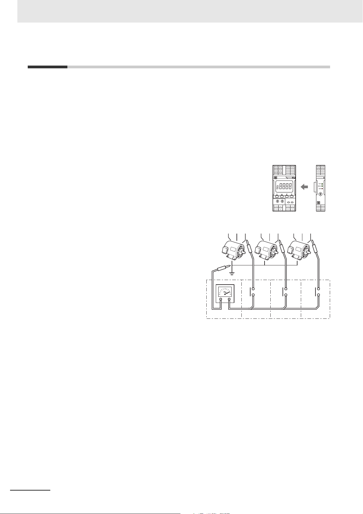
The K7GE-MG measures the insulation resistance by the same detection principle (Megger method) as
a Megohmmeter.
To measure the insulation resistance using the K7GE-MG, it is necessary to
combine one Main Unit with at least one Probe Unit.
The functions of the Main Unit and Probe Unit are
shown in the figure on the right.
The Main Unit corresponds to a Megohmmeter,
and the Probe Unit corresponds to a
measurement probe with internal contacts. The
Main Unit turns ON these contacts in sequence
and measure multiple loads individually.
Up to eight Probe Units can be connected to one
Main Unit.
K7GE-MG supports a motor as a measurement load. If you want to measure other loads such as a
heater or transformer, carefully study the operating specifications of the K7GE-MG before use.
1 - 2
Insulation Resistance Monitoring Device User’s Manual (N224)
Page 23
1-2 Features
Note The above diagram shows only the parts of the internal circuit of the K7GE-MG that are
necessary for explanation.
The following features make the K7GE-MG convenient and safe to use.
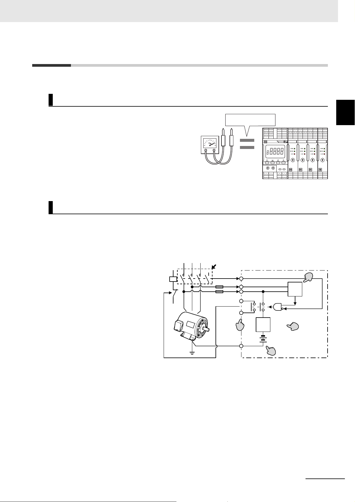
Uses the Same Detection Principle as a Megohmmeter
1 Overview
1-2 Features
The K7GE-MG measures the insulation
resistance by the same detection principle
Megger method
(Megger method) as a Megohmmeter. Therefore,
the inspection data of the Megohmmeter can be
used, and the smooth introduction of this system
is possible.
Megohmmeter
K7GE-MG
More Support for the Safety Functions
• The K7GE-MG is always monitoring the OFF state of the loads and the power line. K7GE-MG does
not start measurement even if it receives a measurement start signal during load operation. In
addition, K7GE-MG will stop the measurement immediately if the load restarts during the
measurement.
• In addition, the K7GE-MG is
equipped with an overcurrent
limit circuit.
This limits the following
overcurrents to safe levels:
- Instantaneous overcurrent
that flows when the load is
restarted during
measurement.
- Overcurrent that flows when
the insulation resistance
value is extremely low.
MC MC-a
Interlock
Turn OFF
Auxiliary
OFF
contact
L2
L3
Status output
during
measurement
PE
K7GE-MG
Current
limiter
Megger voltage
(50 VDC)
Voltage
monitoring
Overcurrent
prevention
Disconnection
(turn OFF)
monitoring
Disconnection
(turn OFF) OK
Start measurement
1
• To reduce equipment damage
and prevent electric shock, the
K7GE-MG has a low Megger
voltage of 50 VDC*.
* Even if the Megger voltage is 50 VDC, it does not affect the measurement accuracy.
• The K7GE-MG provides a contact output that indicates that measurement is in progress. You can
design an interlock circuit that prevents the load from restarting during the measurement.
Insulation Resistance Monitoring Device User’s Manual (N224)
1 - 3
Page 24
1 Overview
K7GE-MG
8 Units max.
Note The above diagram shows only the parts of the internal
circuit of the K7GE-MG that are necessary for explanation.
MC
L3
PE
K7GE-MG
Contact OFF
except during
measurement
Megohmmeter
Measurement current of the
Megohmmeter does not flow
Control
panel
PE
PE
L3
L2
Trigger
input
MC
MC-a
Supports Multiple Channel Measurement
K7GE-MG can be measured up to eight channels per Main Unit by adding
more Probe Units. This reduces cost and installation space per channel.
Periodic Inspection by a Megohmmeter Is Possible with the
K7GE-MG Installed
The K7GE-MG is cut off from the load by the
internal dry contact except during measurement.
This allows inspection using a Megohmmeter
without disconnecting the wiring.
Easy Retrofitting to the Equipment
• The signal wire of the K7GE-MG can be connected in parallel with the
secondary output terminal of the contactor and the PE terminal of the
load. Therefore, it is not necessary to perform large-scale wiring again.
• If you connect the auxiliary contact of the contactor to the trigger input
terminal of the K7GE-MG, you can use it as a measurement start signal. It
contributes to the reduction of parts because no additional sequence is
required.
1 - 4
Insulation Resistance Monitoring Device User’s Manual (N224)
Page 25
Enables Remote Trend Monitoring
• K7GE-MG automatically collects the measured
values of loads with the communications
function. You can monitor the equipment from a
remote location. Remote monitoring greatly
reduces the man-hours required to measure
and collect data with the Megohmmeter while
patrolling FA systems and facilities.
Measurement
value
Alarm value 1
Alarm value 2
'xx/ 1 2 3 4 5 6 7 Year/Month
Communications converter
Load 1
Load 2
Load 3
1 Overview
PC
1-2 Features
1
Insulation Resistance Monitoring Device User’s Manual (N224)
1 - 5
Page 26
1 Overview
K7GE-MG M
□
(1) (2) (3)
K7GE-MG 1
(1) (2)
1-3 Model Number Legend
This section shows the model number legend of the K7GE-MG Main Unit and Probe Units.
• Main Unit
(1) (2) (3) Meaning
Base model Unit type Power supply voltage
K7GE-MG Insulation Resistance Monitoring Device
M Main Unit
A 100 to 240 VAC power supply
D 24 VAC/VDC power supply
• Probe Unit
(1) (2) Meaning
Base model Unit type
K7GE-MG Insulation Resistance Monitoring Device
1 Probe Unit
Refer to A-1 Specifications on page A-2 for the specifications of each model.
1 - 6
Insulation Resistance Monitoring Device User’s Manual (N224)
Page 27
1 Overview
Note The above diagram shows only the parts of the internal
circuit of the K7GE-MG that are necessary for explanation.
1-4 Insulation Resistance Measurement
and Monitoring System
K7GE-MG is automated according to the procedure of manual measurement and monitoring by
Megohmmeter.
The flowchart of measurement and monitoring of K7GE-MG is shown below together with manual
measurement by Megohmmeter.
MC
MC-a
MC
MC-a
Auxiliary
contact
OFF
K7GE-MG
L3
Start measurement
Discharge
of electric
charge
Apply
Megger
voltage
surement and Monitoring System
1-4 Insulation Resistance Mea-
1
PE
Megohmmeter
Step Manual measurement by the Megohmmeter Step Automatic measurement by the K7GE-MG
0
Load operation in progress
Turn OFF the contactor and disconnect the loads from
1
the power line
Waits until the auxiliary contact turns OFF (trigger
0
signal ON)
Trigger signal ON with the contactor OFF
→ Measurement operation starts when the trigger
1
signal is ON
Waits for the loads to stop completely
2
Wait for the loads to stop completely (visual)
(automatic standby based on setting parameters,
2
default value: 10 s)
Wait for the discharge of electric charge accumulated
in the wiring
3
(Decide the time through experience or residual
voltage measurement)
4
Place the probe on the load and apply Megger voltage
Performs forced discharge of electric charge by the
built-in resistor of the K7GE-MG
3
(Waits for 20 s while limiting the peak value of the
discharge current to 1 mA max.)
Internal contact of the Probe Unit turns ON, and
4
application of the Megger voltage starts
Applies Megger voltage until the measurement value
Wait for the measurement value to stabilize (charging
5
time to the wiring capacity)
stabilizes
(Continues the measurement for the time set in the
5
Time to Wait to Stabilize setting parameter, default
value: 60 s)
6
Read the insulation resistance value
7
Remove the probe from the load
Determine if the measurement value is normal or an
8
error
9
If there is more than one load, measure the next load
Record the measurement value and end the series of
10
operations
Insulation Resistance Monitoring Device User’s Manual (N224)
6
Measures the insulation resistance value
The contact of the Probe Unit turns OFF, and
7
application of the Megger voltage stops
Compares the set alarm value and measurement
8
value, and performs alarm output
9
If there is more than one load, measures the next load
Check the measurement value from the display on the
10
front part, or read and record it remotely
1 - 7
Page 28
1 Overview
(A)
(A)
(B)
(C)
(D)
(E)
(A)
(A)
(B)
(C)
Main Unit Probe Unit
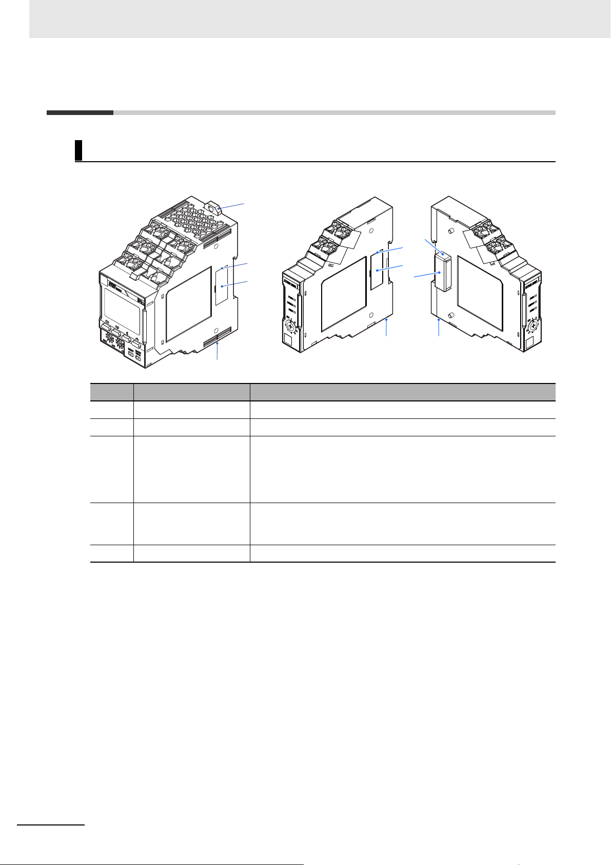
1-5 Nomenclature and Functions
Appearance
Symbol Name Operation
(A) DIN Track mounting hook Used for mounting to the DIN Track.
(B) Right connector Connects the Probe Unit.
(C) Right connector cover A cover for preventing the entry of dust and dirt into the connectors.
Remove this cover when combining the Main Unit and Probe Units, and
during expansion of Probe Units.
However, use the Probe Unit on the extreme right without removing this
connector cover.
(D) Left connector cover A cover for preventing the entry of dust and dirt into the connectors.
Remove this cover when combining the Main Unit and Probe Units, and
during expansion of Probe Units.
(E) Left connector Connects to the Right connector.
1 - 8
Insulation Resistance Monitoring Device User’s Manual (N224)
Page 29
Front Section: Main Unit
(A)
(B)
(C)
(D)
(E)
(F)(G)(H)
(I)
(J)
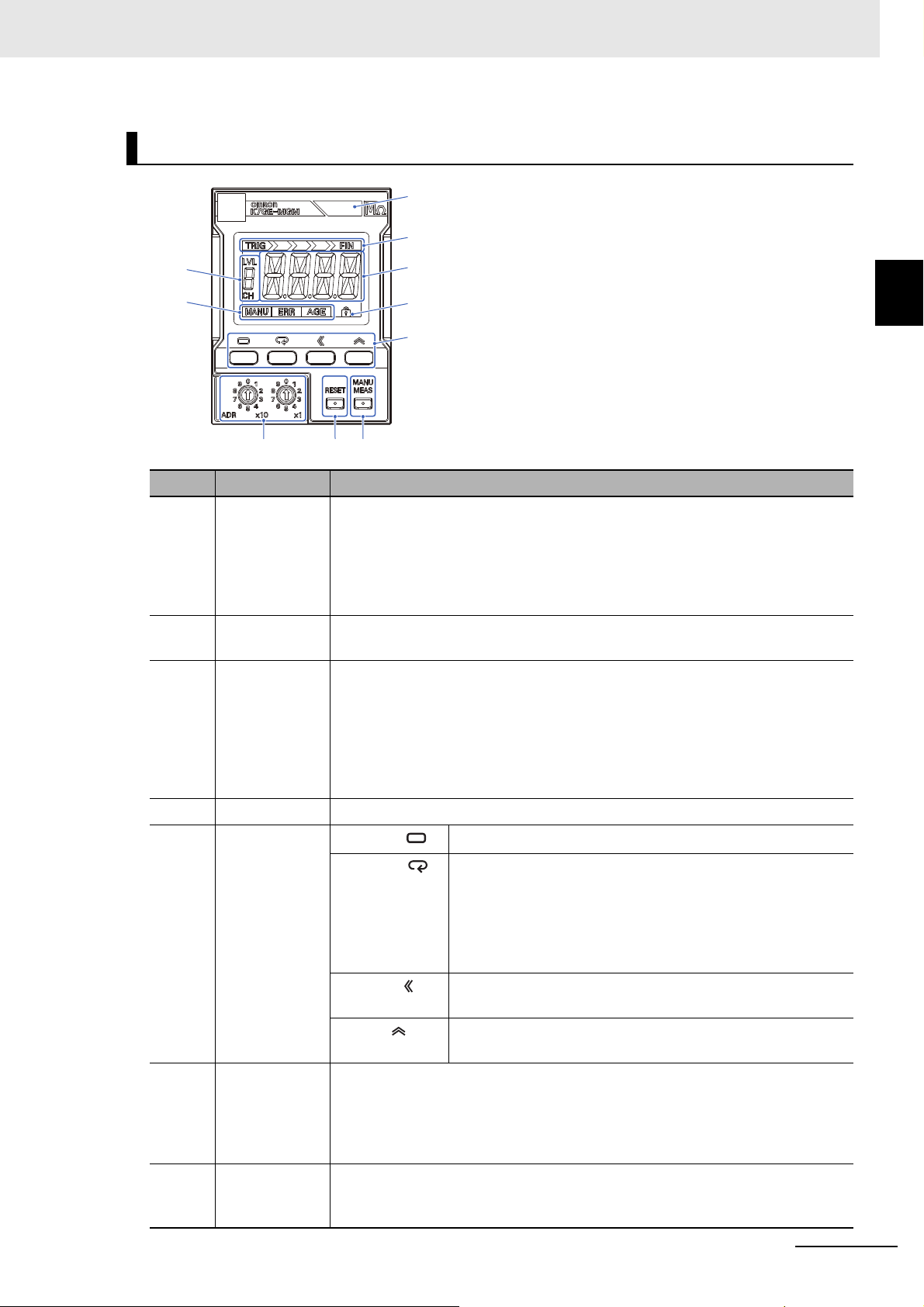
Symbol Name Operation
(A) Alarm output
indicator
Displays the alarm judgment results of automatic measurement in three colors.
Green: Normal
Yellow: Warning (Alarm 1 occurrence)
Red: Critical (Alarm 2 occurrence)
If the status is different across multiple channels, the display color is decided in the
priority order of red (critical) > yellow (warning) > green (normal).
1 Overview
1-5 Nomenclature and Func-
tions
1
(B) Measurement
step indicator
The automatic measurement operation consists of several steps. This indicator
shows the progress of the step from the start to the end of the measurement.
(C) Main display The following contents are displayed in the operating status of the Main Unit.
Measuring operation: The remaining seconds until the measurement
completes are counted down
After measurement completed: The insulation resistance measurement value, or
characters indicating measurement failure
Setting level: The setting parameter name, or setting value
Error occurs: The characters indicating the error status
(D) Protect indicator Indicates that the protect function of the setting parameter is set.
(E) Operation keys
Level Key ( )
Mode Key ( )
Selects the setting level.
Selects the setting parameter of the Initial Setting Level and
Communications Setting Level.
Displays the measurement value of each channel at the
Operation Level. Also used to select between
enabling/disabling of measurement value display automatic
scroll.
Shift Key ( )
Sets the parameter value to a changeable state. Used for digit
shift in the changeable state.
Up Key ( )
(F) Manual
Measurement
Key
Selects to start or end manual measurement. Manual measurement is used to
check the operation when the system is started up. Automatic measurement
requires a trigger signal to start measurement, but manual measurement does not
require a trigger signal. You can use manual measurement in the same way as a
Megohmmeter.
Increments the value when the parameter is in a changeable
state.
(G) Reset Key Selects to return to the power reset status. Even if the measuring operation is in
progress, priority is given to the Reset Key, and measurement stops to return to the
power reset status. The Reset Key is enabled only in the Operation Level.
Insulation Resistance Monitoring Device User’s Manual (N224)
1 - 9
Page 30
1 Overview
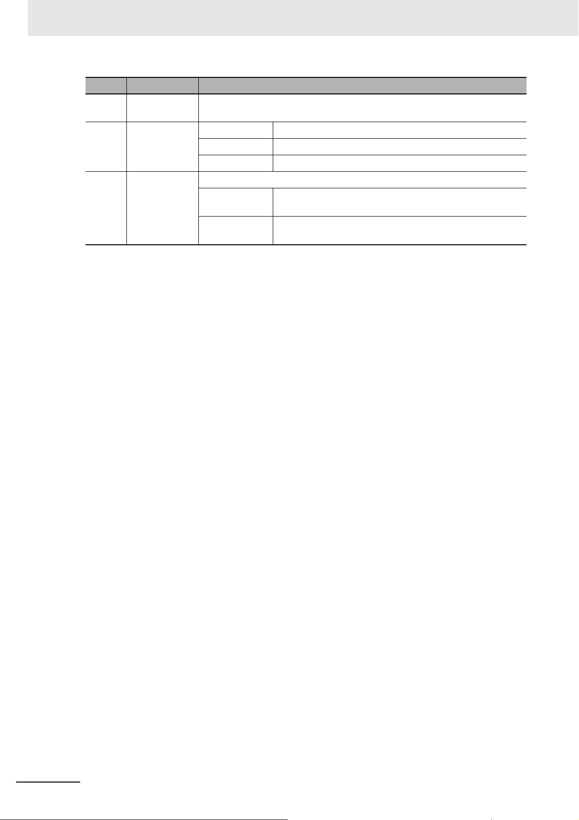
Symbol Name Operation
(H) Unit Number
(I) Status display MANU Indicates the manual measurement state.
(J) LVL/CH display Displays the level*, or the value of the channel number.
* Refer to 5-1 Levels on page 5-2 for information on the levels.
Sets to set the unit number during communications.
Setting Switch
ERR Indicates that a system error occurred.
AGE Indicates that it is time to replace the Main Unit (guideline).
LVL Indicates that the value displayed in the LVL/CH display is the
"Level".
CH Indicates that the value displayed in the LVL/CH display is the
"Channel".
1 - 10
Insulation Resistance Monitoring Device User’s Manual (N224)
Page 31

1 Overview
(A)
(B)
(C)
(D)
1-5 Nomenclature and Func-
Front Section: Probe Unit
tions
1
Symbol Name Operation
(A) PWR indicator (green) Indicates that the Probe Unit power is ON.
(B) MEAS indicator (green) Indicates that measurement is in progress for the load connected to
the Probe Unit.
(C) ALM indicator (red) Indicates that an alarm occurred in the load connected to the Probe
Unit.
(D) Channel Number Setting
Switch
Sets a unique channel number for each Unit when multiple Probe
Units are added.
Insulation Resistance Monitoring Device User’s Manual (N224)
1 - 11
Page 32

1 Overview
(A)
(E)
(D)
(B)
(C)
(H)
(I)
(F)
(G)
Terminal Section: Main Unit
Symbol
(A) 1 and 2 Operation
Terminal
Number
Name Operation
Connect the operation power supply to the Main Unit.
power supply
(B) 3 and 4 Trigger input Input terminals of the external contact from where a trigger signal is
applied.
No. 3: Collector of the NPN transistor, No. 4: Emitter of the NPN transistor
(C) 5 and 6 RS-485 Connect the RS-485 communications line.
No. 5: +, No. 6: -
(D) 7 PE A protective earthing terminal.
(E) NC NC Do not connect anything to this terminal.
(F) 13 and 14 ALM 1 output Compares the measurement value and alarm value 1, and outputs an
alarm.
No. 13: Collector of the NPN transistor, No. 14: Emitter of the NPN
transistor
(G) 15 and 16 ALM 2 output Compares the measurement value and alarm value 2, and outputs an
alarm.
No. 15: Collector of the NPN transistor, No. 16: Emitter of the NPN
(H) 17 and 18 Status output
during
measurement
transistor
Provides notification that measurement is in progress. The output is
normally open (OFF) You can use this output to design an interlock circuit
to prevent accidental restart of the load during measurement operation.
No. 17: Collector of the NPN transistor, No. 18: Emitter of the NPN
transistor
(I) 19 and 20 Self-diagnosis
error output
Provides notification about system error in the Main Unit. The output is
normally closed (ON).
No. 19: Collector of the NPN transistor, No. 20: Emitter of the NPN
transistor
1 - 12
Perform the wiring according to Section 3 Installation and Wiring.
Insulation Resistance Monitoring Device User’s Manual (N224)
Page 33

Terminal Section: Probe Unit
(A)
(B)
1 Overview
1-5 Nomenclature and Func-
tions
1
Symbol
Terminal
Number
Name Operation
(A) 1 and 3 Voltage input Connect the load terminals.
No. 1: Connect the R-phase in a 3-phase system, and the
L-phase in a single-phase system
No. 3: Connect the S-phase in a 3-phase system, and the
N-phase in a single-phase system
Use the terminal No. 1 to discharge the electric charge
and apply the Megger voltage.
(B) NC NC Do not connect anything to this terminal.
Insulation Resistance Monitoring Device User’s Manual (N224)
1 - 13
Page 34

1 Overview
1-6 Internal Block Diagram
This is an internal block diagram of the state when the Main Unit and the Probe Units are connected.
The following describes the main configuration elements.
RS-485
ALM 1 and ALM 2
outputs
Self-diagnosis
error output
Status output during
measurement
Display
switch
RS-485
driver
Trigger
input
Microcomputer
Measurement
Megger
voltage
Current
limiter
Power supply
MC
M
Probe Unit 1Main Unit
Discharge
of electric
charge
PE
MGR
I/O Bus
MC-a
Megger
Apply
voltage
L3PE
L2
Voltage
monitoring
Probe
Unit
control
MC
M
Display
switch
Probe Unit 2
...
Trigger Input
Connect an external contact, and then starts the measurement operation by a signal from this
contact.
When the auxiliary contact of a contactor is connected to a trigger input terminal as an external
contact, the measurement operation can be started at the time the contactor is turned OFF, that is,
when the load is turned OFF from the power line.
Voltage Monitoring
The voltage in the load lines is monitored to determine whether the load is turned ON or turned OFF.
This monitoring is performed at all times, and even when the measurement start signal is input, the
measurement operation does not start if the load is turned ON. Also, even if measurement is
progressing normally, it immediately stops if the load is turned ON during the measurement.
Discharge of Electric Charge
A parasitic capacitance component due to the wiring is present between the charged sections of the
load and the PE. Therefore, even if the contactor is turned OFF, the electric charge accumulated in
the parasitic capacitance component is not discharged immediately. It would take several minutes
for the electric charge to be discharged naturally, so this circuit forcibly discharges the charge. In the
case of a simple short circuit, excessive short-circuit current flows instantaneously, and therefore, by
having a resistance component, the current can be limited to a level where it does not cause any
problem. This processing for the discharge of electric charge is performed before the application of
a Megger voltage.
1 - 14
Insulation Resistance Monitoring Device User’s Manual (N224)
Page 35

1 Overview
Megger Voltage
Generates a voltage of 50 VDC.
Apply Megger Voltage
Turns ON the internal contact and applies Megger voltage to the load.
Measurement
Measures the current flowing through the insulation resistance. Since Megger voltage is a known
value, the insulation resistance value can be calculated from the Megger voltage and the current
value.
Current Limiter
If the load is turned ON when applying a Megger voltage, it is detected by the voltage monitoring
circuit and the measurement operation stops. However, due to a slight time lag, excessive current
flows between the charged sections of the load and the PE at the moment the load is turned ON.
The same thing happens when the insulation resistance value is extremely low even if the load is
properly turned OFF. To protect the load and the peripheral equipment, as well as the internal circuit
of the K7GE-MG from such an overcurrent, the K7GE-MG is equipped with a current limiter circuit
which limits the overcurrent.
1-6 Internal Block Diagram
1
Insulation Resistance Monitoring Device User’s Manual (N224)
1 - 15
Page 36

1 Overview
MC
MC-a
Measurement start signal
L3
L2
PE
Status output during measurement
Alarm output
Interlock
Measurement
starts at auxiliary
contact OFF
MC
Alarm output
MC MC
MC-a
Measurement start signal
PE
Status output during
measurement
Interlock
Measurement
starts at auxiliary
contact OFF
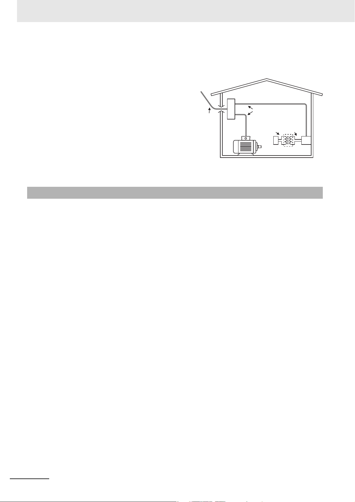
1-7 System Configurations
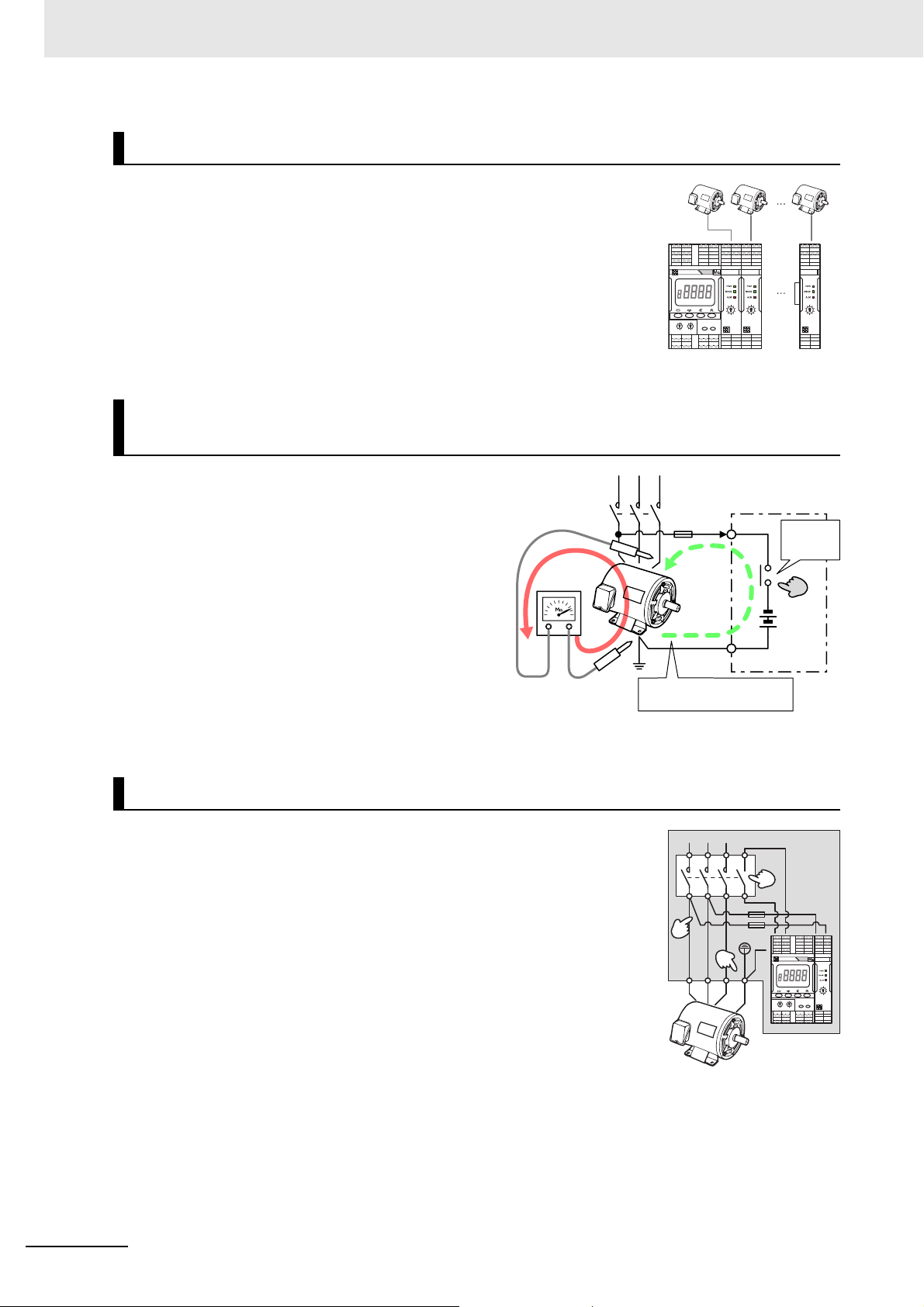
Minimum Configuration
This is the minimum configuration for monitoring the insulation resistance using the K7GE-MG.
The auxiliary contact of the contactor inserted in
front of the load can be used as the measurement
start signal (trigger signal).
You can check the measurement value from the
display on the front part.
The alarm output can be used for external
notification. There are two alarm outputs, and by
setting a threshold value for each alarm output,
judgment can be performed in two stages.
The K7GE-MG has the "Status output during
measurement" terminal that is turned on during
measurement operation. This allows you to
design an interlock circuit that will not restart the
load during measurement operation.
Measurement of Multiple Channels
This configuration is used when monitoring multiple loads collectively.
Design a system configuration that simultaneously
turns ON and OFF the contactors installed on the
loads. The K7GE-MG performs sequential
measurement for one load at a time upon
receiving the measurement start signal (trigger
signal). However, a load that is turned ON at the
time of measurement is treated as "measurement
failed".
In an application such as a duplex alternating pump,
you can use the K7GE-MG by constructing a
sequence in which a trigger signal is input at the time
all loads (pumps) are simultaneously OFF (when
neither water supply nor draining is performed).
In cases where it is not possible to realize the timing
when all loads are simultaneously OFF, use two sets
of the K7GE-MG Main Unit + Probe Units.
1 - 16
Insulation Resistance Monitoring Device User’s Manual (N224)
Page 37

1 Overview
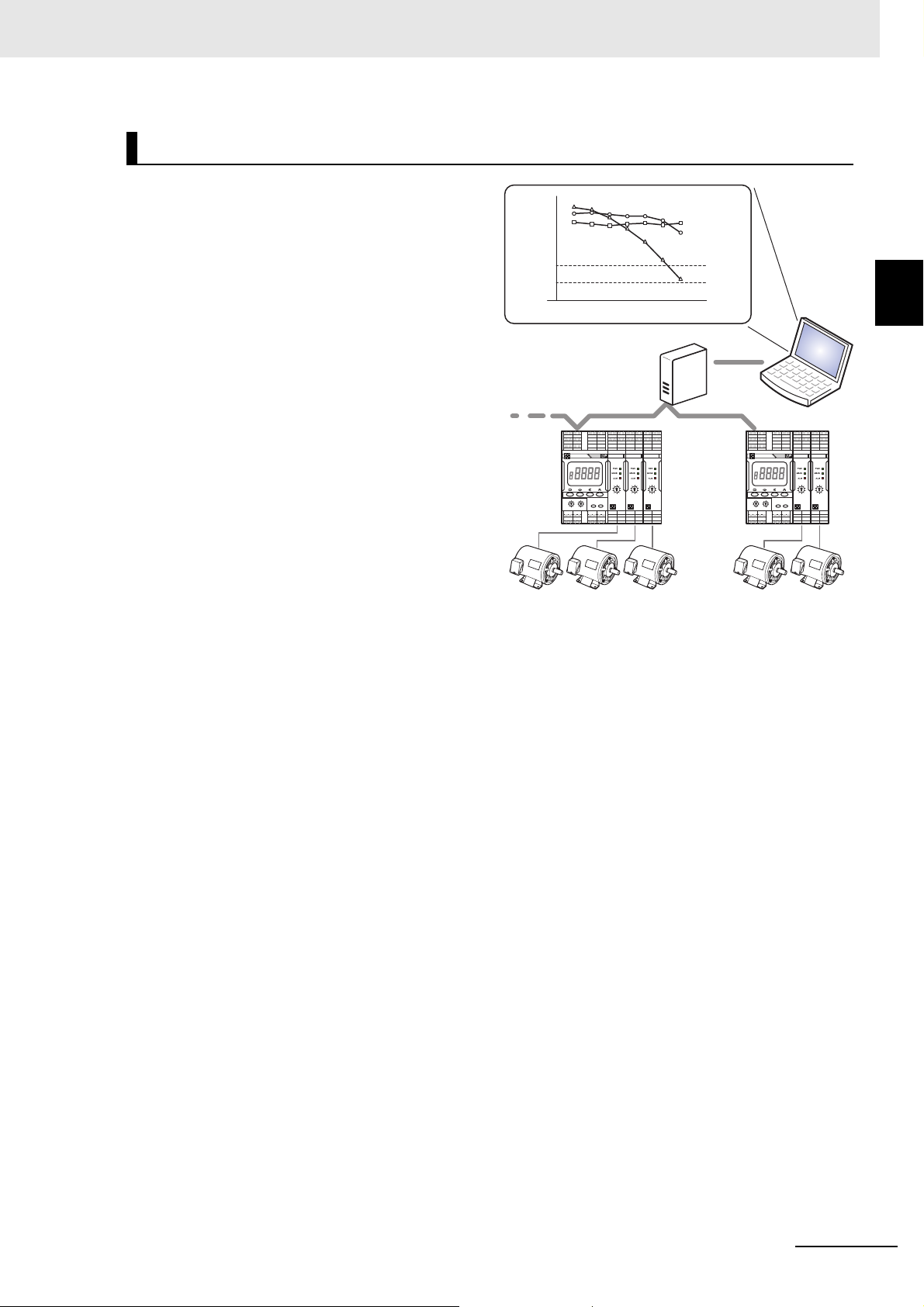
Remote Monitoring by the PLC or PC
This configuration is used when performing remote monitoring of the measurement values with a PLC
or PC as the host.
1-7 System Configurations
When a PC is used as the host, you can
use the K7GE-MG by converting the
Communications
converter
RS-485 to USB or Ethernet using a
commercial communications converter.
The protocol is compatible with
CompoWay/F and Modbus RTU.
The K7GE-MG does not have a function to
retain the past measurement value data.
31 Node max.
500 m max.
RS-485
Also, data is lost when the power is turned
OFF. Therefore, read the measurement
values when the measurement ends and
before the next measurement starts, and
before the power of the Main Unit is turned
OFF.
To know the timing of measurement end, you can use status output during measurement in the K7GE-MG. Status output
during measurement turns ON when the measurement operation starts and turns OFF when measurement ends. This
change from ON to OFF is the timing when measurement ends.
You can also use the communications commands to read the flags synchronous with the status output during
measurement.
PC
1
PLC
Customization of HMI from the Touch Panel
This configuration is used when a touch panel is installed on the front panel to customize the HMI for
checking the measurement values and performing the alarm reset operation.
A connection is established with the touch panel
via the RS-485, and the touch panel is used as
the master.
The protocol is compatible with CompoWay/F and
Modbus RTU.
The K7GE-MG does not support the multi-master
system. Therefore, to further connect a host
system and perform remote monitoring, connect
the host system to the touch panel, and perform
operations such as reading the measurement
values or changing the setting parameters of the
K7GE-MG via the touch panel.
Refer to the manual of the touch panel in use for
details on communications between the host
system and the touch panel.
Touch panel
OMRON NB-series, etc.
USB or
Ethernet
PC
Ethernet
PLC
RS-485
Insulation Resistance Monitoring Device User’s Manual (N224)
1 - 17
Page 38

1 Overview
Incorrect Correct
M
Inverter
K7GE-MG
M
K7GE-MG
Inverter
Contactor
Incorrect Correct
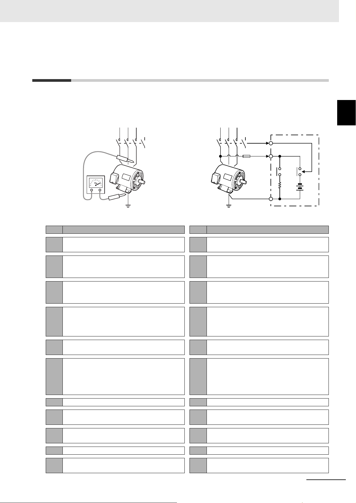
1-8 Safety Precautions
Be sure to install the contactor in front of the load to be measured.
The K7GE-MG uses the same Megger method as a Megohmmeter for detecting insulation resistance.
The Megger method measures resistance values with a measuring circuit connected between the
charged section and the non-charged section. The charged section is usually connected to the power
line and insulated from the ground. Also, the non-charged section is a grounded section such as a
motor frame. The measurement circuit of K7GE-MG is connected between different insulated circuits.
Therefore, if the charged sections turn ON during measurement, it may result in a ground-fault
accident.
M
K7GE-MG
M
Contactor
K7GE-MG
Also, although the voltage is low, applying a Megger voltage to the output circuit of the secondary coil of
the inverter may cause an inverter failure.
1 - 18
Insulation Resistance Monitoring Device User’s Manual (N224)
Page 39

Procedure
This section describes the procedure from preparation to startup of the K7GE-MG.
2-1 Procedure . . . . . . . . . . . . . . . . . . . . . . . . . . . . . . . . . . . . . . . . . . . . . . . . . . . . 2-2
(1) Advance Preparation . . . . . . . . . . . . . . . . . . . . . . . . . . . . . . . . . . . . . . . . . . . . . . . . . 2-2
(2) Installation and Wiring . . . . . . . . . . . . . . . . . . . . . . . . . . . . . . . . . . . . . . . . . . . . . . . . 2-3
(3) Initial Setting . . . . . . . . . . . . . . . . . . . . . . . . . . . . . . . . . . . . . . . . . . . . . . . . . . . . . . . 2-5
(4) Test Operation with Manual Measurement . . . . . . . . . . . . . . . . . . . . . . . . . . . . . . . . 2-7
(5) Starting Operation . . . . . . . . . . . . . . . . . . . . . . . . . . . . . . . . . . . . . . . . . . . . . . . . . . . 2-8
Troubleshooting . . . . . . . . . . . . . . . . . . . . . . . . . . . . . . . . . . . . . . . . . . . . . . . . . . . . . . 2-10
2
Insulation Resistance Monitoring Device User’s Manual (N224)
2 - 1
Page 40

2 Procedure
MC MC MC
MC-a
PE
Measurement starts at
auxiliary contact OFF
Status output during
measurement
Alarm output
Measurement start signal
Interlock
!
2-1 Procedure
The procedure for starting actual operation is
shown using a system that measures three loads
as an example.
The procedure is described in the following five
steps.
Steps
(1) Advance Preparation
(2) Installation and Wiring
(3) Initial Setting
(4) Test Operation with Manual Measurement
(5) Starting Operation
The " No. **" in the following description is the
reference number in Troubleshooting at the end of
this section. Refer to the corresponding number
when the operation does not run normally even
after following the procedure.
(1) Advance Preparation
Examine the time until the load stops.
• Measure the time until the load stops after the contactor is turned
OFF. Use the setting value of the Motor Stop Waiting Time setting
parameter as a guide.
Use the value of the load that took the longest time from among the three
loads as a guide.
Use a Megohmmeter to measure the insulation resistance during
normal operation of the target load.
2 - 2
• This is the reference value for deciding the Alarm Value 1 and 2
setting parameters.
Insulation Resistance Monitoring Device User’s Manual (N224)
Page 41

(2) Installation and Wiring
*Sold separately
Connect three Probe Units to one Main Unit.
• Remove the right connector cover of the Main Unit and the left
connector cover of the Probe Units.
Use the Probe Unit on the right end with the right connector cover
attached.
2 Procedure
2-1 Procedure
• Join the connectors together. Make sure that the connectors are
connected firmly without any gap between the Units.
Mounting to DIN Track.
• Pull down the DIN Track mounting hook under the Main Unit and
Probe Units to mount the Units on the DIN Track.
• Secure with the DIN Track mounting hook.
• Install an end plate* on the left and right sides.
Be sure to connect the Units together before mounting them on the DIN
Track.
End plate
2
End plate
DIN Track mounting hook
Insulation Resistance Monitoring Device User’s Manual (N224)
2 - 3
Page 42

2 Procedure
MC
MC-a
L3 L2 L3 L2 L3 L2
M
7
17 18
13 14 15 16
1
2
Main Unit
PE
Trigger
input
Operation
power supply
Status output during
measurement
ALM 1 ALM 2
17 18
1 3 1 33 4 1 3
M M
Probe Unit 1 Probe Unit 2 Probe Unit 3
Wire all connections.
• To be safe, always attach a
fuse (2 A max., fast-blow
type) in the wiring from the
Probe Unit to the load.
• The figure shows a
simplified view of the wiring
for status output during
measurement, and ALM 1
and ALM 2 outputs. Use a
suitable relay according to
the switching capacity of the
output transistor.
• The K7GE-MG provides an
output transistor with
specifications of 24 VDC
(+10%) and 50 mA max.
Supply the operation power from a system different from that of the load. If the same system is used, the power
supply to the K7GE-MG will turn OFF when the load contactor turns OFF, and you may not be able to perform
measurement.
2 - 4
Insulation Resistance Monitoring Device User’s Manual (N224)
Page 43

(3) Initial Setting
* This is reference number in Troubleshooting described at
the end. If the K7GE-MG does not operate properly after
performing the procedure, see the reference number.
Set the channel numbers of the Probe Units.
• Set the channel number of the first Probe Unit to 1 with the rotary
DIP switch on the front.
Observe that it is not a DIP switch on the Main Unit side.
2 Procedure
2-1 Procedure
• In the same way, set the channel number of the second Probe
Unit to 2 and that of the third Probe Unit to 3.
Always set the channel number to a serial number starting from 1.
The K7GE-MG will not operate properly if the channel numbers are not
set sequentially from 1 such as 2, 3 and 4 or 1, 2 and 4.
Turn ON the power supply to the Main Unit.
• The Operation Level is displayed immediately after the power is
turned ON.
---- indicates measurement standby.
Move to the Initial Setting Level.
• Press the Level Key for at least 3 seconds to move from the
Operation Level to the Initial Setting Level.
In the Initial Setting Level, LVL and 0 are displayed together on
the LVL/CH display.
No.1*
3 seconds
TRIG FIN
LVL
1
----
CH
MANU ERR AGE
TRIG FIN
LVL
0
mxch
MANU ERR AGE
2
Set the total number of channels.
The total number of channels is used to perform the processing in
the case of a measurement failure when the Main Unit can no
longer recognize the Probe Units due to a malfunction, etc.
• If the main display part does not display mxch, press the Mode
Key several times to display mxch.
• Press the Shift Key to display the setting value.
The setting value is displayed.
Insulation Resistance Monitoring Device User’s Manual (N224)
TRIG FIN
LVL
0
mxch
MANU ERR AGE
TRIG FIN
LVL
0
1
MANU ERR AGE
2 - 5
Page 44

2 Procedure
1
TRIG FIN
LVL
0
MANU ERR AGE
3
TRIG FIN
LVL
0
MANU ERR AGE
alm1
TRIG FIN
LVL
0
MANU ERR AGE
1 second
----
TRIG FIN
LVL
CH
1
MANU ERR AGE
• Press the Shift key again to change the setting value.
• Press the Up Key several times to set the setting value to 3.
• Press the Mode Key to define the changes.
Repeat the process to set the other parameters.
The digits that can be changed start flashing.
In this example, the total number of channels is set to 3
because three Probe Units are used.
The setting value is overwritten, and the next setting parameter
will be displayed.
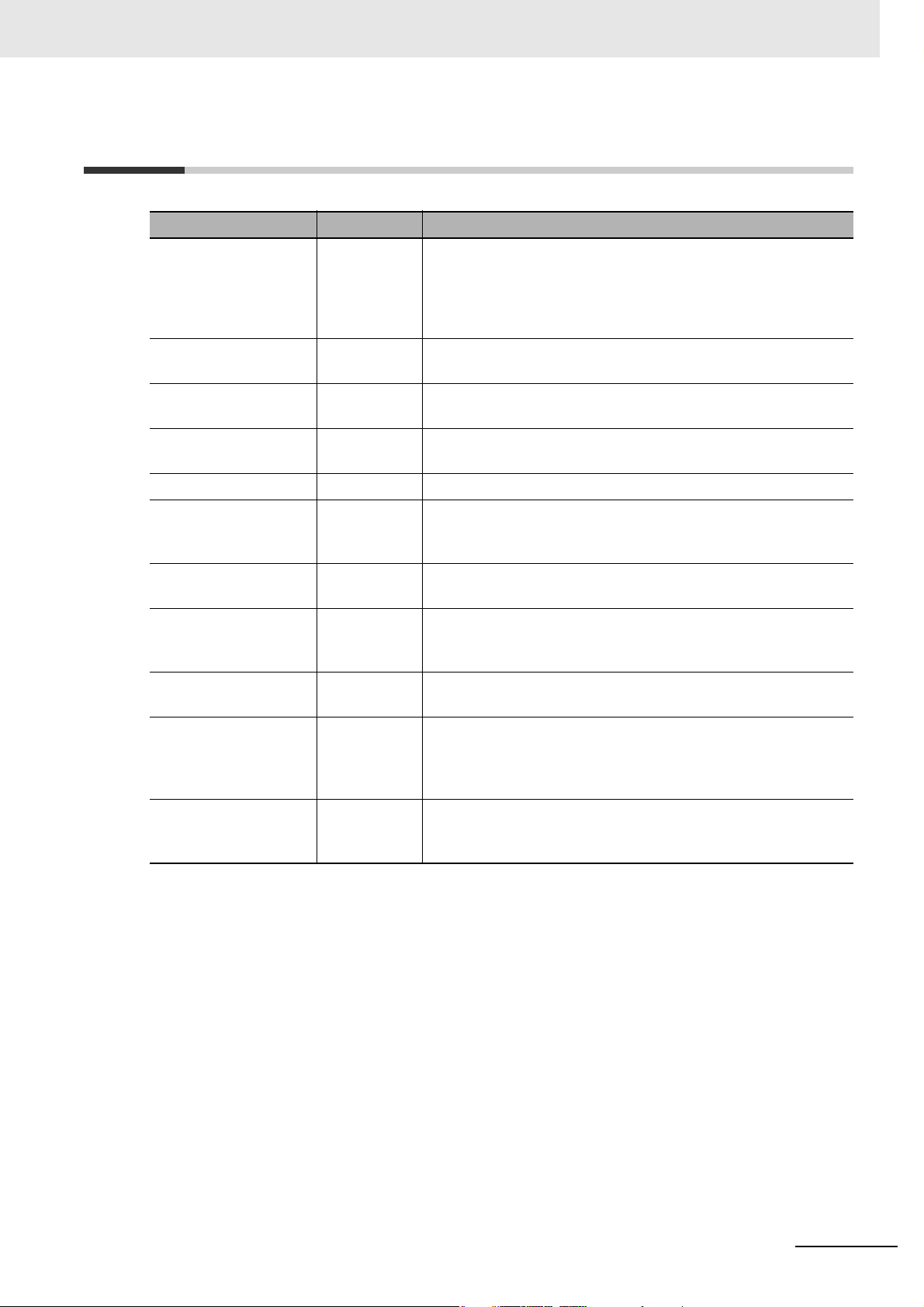
Parameter name Characters Setting value Description
Alarm Value 1 alm1 xx.x (MΩ) If the measurement value dropped below the alarm
value, the alarm output indicator is lit yellow and ALM
1 (warning) will be output. One alarm value 1 is
provided in common for all channels.
Alarm Value 2 alm2 xx.x (MΩ) If the measurement value dropped below the alarm
value, the alarm output indicator is lit red and ALM 2
(critical) will be output. One alarm value 2 is provided
in common for all channels.
Motor Stop Waiting
Time
If you want to use a user-specified critical threshold, set it to alarm value 2. Alarm value 1 is set between the normal
value measured during advance preparation and alarm value 2.
If you do not have a user-defined critical threshold, the alarm value 2 can be set to 1 MΩ recommended by IEC
60034-1 and the motor manufacturer. Alarm value 1 is set between the normal value measured during advance
preparation and alarm value 2.
mtwt xxx (seconds) Set the time until the load stops after the contactor
turns OFF plus a margin.
(Use the time measured during advance preparation
as a guide.)
Return to the Operation Level.
• Press the Level Key for at least 1 second to return to the
Operation Level.
---- indicates measurement standby.
No.2
2 - 6
Insulation Resistance Monitoring Device User’s Manual (N224)
Page 45

(4) Test Operation with Manual Measurement
----
TRIG FIN
LVL
CH
1
MANU ERR AGE
MANU
After xx seconds
TRIG FIN
LVL
CH
3
ERR AGE
9#4
Make sure the load contactor is turned OFF.
• Immediately after returning to Operation Level, the
measurement standby is established without starting
measurement even if the auxiliary contact of the contactor is
turned OFF. Perform manual measurement in this state.
Select the channel to perform manual measurement.
2 Procedure
2-1 Procedure
No.3
2
• Press the Mode Key several times to set the channel number to
perform manual measurement.
Manual measurement is started.
• Press the Manual Measurement Key at least for 3 seconds to
start manual measurement.
MANU indicator will light.
• Manual measurement performs continuous monitoring
regardless of the trigger signal, and does not provide ALM 1
and ALM 2 outputs.
Make sure the measurement value is suitable.
• Make sure the measurement value stabilizes within 60 seconds.
If the measurement value does not stabilize even within 60 seconds,
return to the Initial Setting Level, and increase the setting value of the
Time to Wait to Stabilize (stwt) setting parameter. Up to 99 seconds can
be set.
This setting value is used for the waiting time from when a Megger
voltage is applied during automatic measurement until the measurement
value stabilizes.
No.4
No.5
MANU
MEAS
3 seconds
Measurement
value
Within 60 seconds?
TRIG FIN
LVL
3
----
CH
MANU ERR AGE
TRIG FIN
LVL
3
7"6
CH
MANU
ERR AGE
• Make sure that the measurement value is not significantly
different from the value previously measured with the
Megohmmeter.
If the measurement value is not stable due to the influence of noise,
change the setting value of the Average processing (avg) setting
parameter to ON (with averaging processing) in the Initial Setting Level.
When this parameter is set to ON, the average value of eight
measurements is treated as the measurement value.
Insulation Resistance Monitoring Device User’s Manual (N224)
No.6
2 - 7
Page 46

2 Procedure
MANU
MANU
MEAS
TRIG FIN
LVL
CH
1
ERR AGE
1 second
----
MANU
TRIG FIN
LVL
CH
1
ERR AGE
--96
CH1 CH2 CH3
MANU
TRIG FIN
LVL
CH
1
ERR AGE
--81
CH1 CH2 CH3
MANU
TRIG FIN
LVL
CH
1
ERR AGE
--61
CH1 CH2 CH3
MANU
TRIG FIN
LVL
CH
1
ERR AGE
--61
CH1 CH2 CH3
Manual measurement is ended.
• Press the Manual Measurement Key for 1 second to end
manual measurement, and the K7GE-MG will return to
measurement standby in the Operation Level.
In addition, the measurement will be ended automatically 3
minutes after the start of manual measurement.
Perform manual measurement for the remaining channels as well.
• Repeat the process to perform manual measurement for the
remaining channels as well, and check the measurement
values.
(5) Starting Operation
Turn ON the load contactor.
• Make sure the peripheral equipment including loads are
operating correctly.
Turn OFF the load contactor.
• Automatic measurement is started.
TRIG indicator will light on the measurement step indicator.
The main display part shows the approximate number of
seconds required to complete the measurement, and it will be
counted down.
• The discharge of electric charge is performed after the time set
in the Motor Stop Waiting Time setting parameter has elapsed.
The measurement step indicator moves to the next step. The
first arrow indicates that the discharge of electric charge is in
progress.
The MEAS indicator on channel 1 of the Probe Unit will light in
measurement operation.
This process always requires 20 seconds.
2 - 8
• A Megger voltage is applied and it is held for approximately 60
seconds until the measurement value stabilizes.
The measurement step indicator moves to next step. The
second arrow indicates waiting for stability.
• Sampling is performed. It takes about 1 second.
The measurement step indicator moves to next step. The third
arrow indicates that measurement is in progress.
Insulation Resistance Monitoring Device User’s Manual (N224)
Page 47

• The measurement of channel 1 is completed, the alarm
MANU
TRIG FIN
LVL
CH
2
ERR AGE
--81
CH1 CH2 CH3
judgment is performed for the confirmed measurement value,
and the results are applied in the alarm output, the alarm output
indicator, and the ALM indicator of the Probe Unit.
Next, the measurement for channel 2 will start.
The MEAS indicator on channel 2 of the Probe Unit will light.
You can perform the Motor Stop Waiting Time setting parameter
only during the first measurement. The procedure for channel 2
onward will be started from the discharge of electric charge.
• When the measurement is complete for all channels, the
confirmed measurement values are displayed on the main
display part.
FIN indicator will light on the measurement step indicator.
Check the results of automatic measurement.
TRIG
LVL
3
-9#2
CH
ERR AGE
MANU
2 Procedure
FIN
CH1 CH2 CH3
2-1 Procedure
2
• Press the Mode Key to display the measurement results of
each channel.
Start actual operation.
• Start actual operation if there is no problem in the series of
operations of the K7GE-MG and the operation of peripheral
equipment including loads and the measurement values.
No.7
TRIG
LVL
1
-9&8
CH
ERR AGE
MANU
TRIG
LVL
2
-8'4
CH
MANU
ERR AGE
TRIG
LVL
3
-9#2
CH
MANU
ERR AGE
FIN
FIN
FIN
Insulation Resistance Monitoring Device User’s Manual (N224)
2 - 9
Page 48

2 Procedure
8888
TRIG FIN
LVL
CH
8
MANU ERR AG E
psel
TRIG FIN
LVL
CH
1
MANU ERR AGE
MANU
TRIG FIN
LVL
CH
1
ERR AGE
--81
MANU
TRIG FIN
LVL
CH
1
ERR AGE
trig
FIN
MANU
TRIG
LVL
CH
1
ERR AGE
-----
5 s
5 s
5 s
MANU
LVL
CH
2
ERR
--
MANU
LVL
CH
3
ERR
--
Troubleshooting
If the K7GE-MG does not operate properly after performing the procedure, see the correction in the
table below corresponding to the reference number " No. **" in the procedure.
No. Problems Cause Correction
1 ERR indicator is lit,
2 psel is displayed
3 TRIG indicator
A system error occurred.
and 8888 is
displayed.
The channel numbers of the
Probe Units may be
duplicated.
The Level Key ( ) was
in the LVL 1.
pressed for less than 1
second, which caused the
K7GE-MG to move to the
Communications Setting
Level.
After returning to the
lights on the
measurement step
indicator, and
countdown of
seconds starts on
the main display
Operation Level, the auxiliary
contact of the contactor is
turned OFF, so the trigger
signal is accepted and
automatic measurement is
started.
part.
trig flashes. After returning to the
Operation Level, the auxiliary
contact of the contactor is
turned OFF, so the trigger
signal is accepted and
automatic measurement is
started. However, the auxiliary
contact is immediately turned
ON and the measurement is
interrupted.
Check again that the channel
numbers of the Probe Units
are correctly set to
consecutive numbers starting
from 1.
Press the key for at least 1
second. Press the Level key
( ) for at least 1 second to
return to the Operating Level
even in the Communications
Setting Level.
Press the Reset Key for at
least 3 seconds to forcibly end
the measurement.
If the trigger signal occurs
unintentionally, check the
wiring of the trigger input
terminal again.
You can perform manual
measurement even in this
state.
If the trigger signal occurs
unintentionally, check the
wiring of the trigger input
terminal again.
2 - 10
4 The channel display does not change
even after pressing the Mode Key ( ).
The Maximum Number of
Channels setting parameter
may not be set correctly.
The channel
display is scrolled
automatically every
5 seconds.
The Mode Key ( ) was
pressed for 3 seconds, which
resulted in measurement
value display automatic scroll.
Insulation Resistance Monitoring Device User’s Manual (N224)
Check again that the setting
value is set to 3, which is the
total number of Probe Units.
Press the Mode Key ( )
again for 3 seconds to cancel
automatic scroll.
Page 49

2 Procedure
FIN
MANU
TRIG
LVL
CH
3
ERR AGE
-----
No. Problems Cause Correction
5 The manual
measurement does
not start but the
main display part
flashes when the
Manual
Measurement Key
is pressed.
Even if MANU
indicator is lit, the
measured value is
not displayed.
TRIG FIN
LVL
3
fail
CH
MANU
ERR AGE
The Mode Key ( ) was
pressed for 3 seconds, which
resulted in measurement
value display automatic scroll.
Manual measurement cannot
start during automatic scroll.
The measurement is aborted
because the safety function is
activated. This function is
enabled when the load is
turned ON or the insulation
resistance is detected
extremely low. If the load is
not completely stopped, it may
be determined that the load is
turned ON.
The Main Unit cannot
recognize the Probe Unit of
this channel. The Units may
not be connected properly.
Press the Mode Key ( )
again for 3 seconds to cancel
Measurement Value Display
Automatic Scroll, and then
press the Manual
Measurement Key.
Make sure that the load is
completely stopped before
performing the manual
measurement.
Also, check the wiring
between the load, contactor,
and K7GE-MG again.
Check the connection
between the Units again.
2-1 Procedure
2
6 The measurement value is significantly
different from the value measured by the
Megohmmeter.
7 The measurement
value is not
displayed on the
channel, but fail
TRIG FIN
LVL
2
fail
CH
MANU
ERR AGE
is flashing.
It is possible that the manual
measurement was performed
with the electric charge
remaining on the wiring and
other parts.
The measurement for this
channel is stopped because
either the load was turned ON
during measurement, or the
K7GE-MG detected that the
insulation resistance is
extremely low.
The Main Unit cannot
recognize the Probe Unit of
this channel. The Units may
not be connected properly.
The manual measurement
does not allow forced
discharge of electric charge.
In the same way as measuring
with a Megohmmeter, wait for
the charge to be completely
discharged before performing
manual measurement.
Check again that until the start
of automatic measurement,
the contactors of all loads turn
OFF, and all loads stop
completely within the time
period of the Motor Stop
Waiting Time setting
parameter.
Also, check the wiring
between the load, contactor,
and K7GE-MG again.
Check the connection
between the Units again.
Insulation Resistance Monitoring Device User’s Manual (N224)
2 - 11
Page 50

2 Procedure
2 - 12
Insulation Resistance Monitoring Device User’s Manual (N224)
Page 51

Installation and Wiring
This section describes the installation and wiring of the K7GE-MG device.
Before you proceed with installation and wiring, be sure to thoroughly read Precautions
for Safe Use on page 6.
3-1 Dimensions . . . . . . . . . . . . . . . . . . . . . . . . . . . . . . . . . . . . . . . . . . . . . . . . . . . 3-2
3-2 Installation . . . . . . . . . . . . . . . . . . . . . . . . . . . . . . . . . . . . . . . . . . . . . . . . . . . 3-3
3-3 Setting the Channel Number . . . . . . . . . . . . . . . . . . . . . . . . . . . . . . . . . . . . . 3-6
3-4 How to Connect to the Push-In Plus Terminal Blocks . . . . . . . . . . . . . . . . 3-7
3-5 I/O Wiring . . . . . . . . . . . . . . . . . . . . . . . . . . . . . . . . . . . . . . . . . . . . . . . . . . . 3-10
3-6 Wiring the Communications Cable . . . . . . . . . . . . . . . . . . . . . . . . . . . . . . . 3-13
3-7 Setting the Unit Number . . . . . . . . . . . . . . . . . . . . . . . . . . . . . . . . . . . . . . . 3-14
3-8 Connecting to a Load or Contactor . . . . . . . . . . . . . . . . . . . . . . . . . . . . . . 3-15
3
Insulation Resistance Monitoring Device User’s Manual (N224)
3 - 1
Page 52

3 Installation and Wiring
45
90
90
86 (4)
(1.9)
(Unit: mm)
17.5
90
(0.9)
(3)
(7.6)
90
86 (4)
(Unit: mm)
3-1 Dimensions
Main Unit
Probe Unit
3 - 2
Insulation Resistance Monitoring Device User’s Manual (N224)
Page 53

3-2 Installation
Incorrect
Combining Units
• Remove the right connector cover of the Main Unit and the left connector
cover of the Probe Units.
To prevent dust from entering and failure of the internal circuit due to
static electricity, remove the connector covers immediately before
connecting the Units.
Remove the right connector cover by using your nail to lift the notch.
3 Installation and Wiring
3-2 Installation
3
Since the left connector cover is held in place, it may be difficult to remove
it simply by pulling up.
As shown in the figure, you can easily remove the cover by pushing one
of the short sides of the cover and holding up the other short side.
Also, to improve the electrical contact reliability during Unit connection,
the pins of the left connector of the Probe Units are kept slightly higher
than the height of the case. Be careful when handling as the pins may be
damaged if you drop them.
• Join the connectors together.
Make sure that the connectors are connected firmly without any gap
between the Units.
(1)
Pins
Protective
ribs
(2)
Make sure to connect the Units before you mount on the DIN Track.
If you connect the Units by sliding them on the DIN Track after mounting
on the DIN Track, the connectors may be damaged.
Insulation Resistance Monitoring Device User’s Manual (N224)
3 - 3
Page 54

3 Installation and Wiring
(1) (2) (3)
30 mm
above
End plate
End plate
Downward Vertical
Sidewise Lengthwise
Horizontal
Mounting to DIN Track
• Mounting method
After connecting the Units, pull
down all DIN Track mounting
hooks on the bottom.
Next, hook the upper hook of
the K7GE-MG onto the DIN
Track and push in the Units.
Finally, raise all the DIN Track
mounting hooks that were
pulled down and fix the K7GE-MG to the DIN Track.
• Dismounting method
Pull out the DIN Track mounting hooks with a flat-blade screwdriver and
lift the Unit from the bottom to remove it.
Leave at least 30 mm of space between the K7GE-MG and other devices
to allow easy installation and removal.
• Install an end plate on the left and right sides.
To prevent a faulty contact between the connectors due to vibrations,
mount the Units without any gap so that they are pinched between the
end plates. Up to one Main Unit and eight Probe Units can be installed
between End Plates.
• Install the K7GE-MG in the horizontal or vertical
direction as much as possible, although there is
no restriction on the mounting direction.
• Recommended DIN Track
Model Specifications Manufacturer
PFP-100N 1,000 × 35 × 7.3 mm (L × W × H) OMRON
PFP-50N 500 × 35 × 7.3 mm (L × W × H) OMRON
• Recommended end plates
Model Specifications Manufacturer
PFP-M For PFP-100N/PFP-50N OMRON
3 - 4
Insulation Resistance Monitoring Device User’s Manual (N224)
Page 55

Replacing the Units
3 Installation and Wiring
• If a Unit is to be replaced due to
a failure, turn OFF the power,
remove all wires, and then
remove the K7GE-MG from the
DIN Track.
Remove temporarily
Replace
3-2 Installation
3
Insulation Resistance Monitoring Device User’s Manual (N224)
3 - 5
Page 56

3 Installation and Wiring
(3)(2)(1)
(3) (4)(3)(2) (2)(2)(1) (1) (1)
Correct Incorrect Incorrect
MANU
TRIG FIN
LVL
CH
2
ERR AGE
fail
Measurement failed
8888
TRIG FIN
LVL
CH
8
MANU ERR AGE
System error
Measurement
CH2 and CH3
are out of the
scope of
measurement
Maximum Number of
Channels = 1
(default value)
CH1 CH3CH2
3-3 Setting the Channel Number
Set the channel numbers of the Probe Units.
When setting only one Probe Unit, set the channel number to 1.
When setting two or more Probe Units, always set the channel number
starting from 1 and then in order such as 2, 3, etc., and n.
Although operation will be performed normally
even if the channel numbers are not set in the
order of 1, 2, and 3, etc., from the left side, there
must not be any missing or duplicate numbers.
If a number is missing in the channel number setting, "measurement failed"
occurs when the measurement is performed for the missing channel, and if
a number is duplicate, "system error" occurs at the same time when the
power is turned ON. Observe that in either case measurement will not be
performed normally.
If the number of Probe Units is increased to multiple Units, it is necessary to
set the channel number with the Channel Number Setting Switch, and also
set the total number of channels (number of Probe Units) in the Maximum
Number of Channels setting parameter of the Initial Setting Level.
Observe that if you use this setting parameter with the default value, the
Probe Units with channel number 2 and later may be out of the scope of
measurement.
Refer to 5-3 Maximum Number of Channels on page 5-6 for the operation
method of the Maximum Number of Channels setting parameter.
3 - 6
Insulation Resistance Monitoring Device User’s Manual (N224)
Page 57

3 Installation and Wiring
Terminal (insertion) hole
Release hole
Terminal (insertion) hole
Release hole
<Upper side> <Lower side>
r
3-4 How to Connect to the Push-In Plus
Terminal Blocks
Nomenclature
3-4 How to Connect to the Push-In Plus Terminal Blocks
Name Operation
Terminal (insertion) hole Used to insert wires with ferrules, solid wires, and stranded wires.
Release hole Releases the wire when the specified flat-blade screwdriver is inserted.
Also used when inserting stranded wires.
3
Connecting Wires with Ferrules and Solid Wires
Insert the ferrule or solid wire straight into the
terminal block until the end touches the terminal
block.
If you use a ferrule with a conductor length of 10
mm, part of the conductor may be visible after the
ferrule is inserted into the terminal block, but the
product insulation distance will still be satisfied.
If it is difficult to insert fine solid wires, insert the wire with a screwdriver inserted into the release hole,
and then remove the screwdriver while ensuring that the fine solid wire is still held.
<Upper side> <Lower side>
Terminal (insertion) hole
Ferrule
Release hole
Release hole
Ferrule
Terminal (insertion) hole
Connecting Stranded Wires
• Hold a flat-blade screwdriver at an angle and
insert it into the release hole. The angle should
be between 10° and 15°.
If the flat-blade screwdriver is inserted correctly,
you will feel the spring in the release hole.
The terminal block may be damaged if you insert
the screwdriver with excessive force. Operate the
screwdriver with a force of 15 N or less.
• With the flat-blade screwdriver still inserted into
the release hole, insert the wire into the terminal
Insulation Resistance Monitoring Device User’s Manual (N224)
hole until it strikes the terminal block.
• Remove the flat-blade screwdriver from the release hole.
<Upper side>
(1)
Flat-blade screwdriver
Flat-blade screwdriver
(2)
Wire
(3)
10° to 15°
<Lower side>
(3)
Flat-blade
screwdriver
10° to 15°
Flat-blade
screwdrive
(1)
Wire
(2)
3 - 7
Page 58

3 Installation and Wiring
Flat-blade
screwdriver
10° to 15°
10° to 15°
Flat-blade screwdriver
Wire
(1)
(3)
(2)
Flat-blade screwdriver
<Upper side>
Wire
(1)
(3)
(2)
Flat-blade
screwdriver
<Lower side>
Checking Connection
After the insertion, pull gently on the wire to make sure that it will not come
off and the wire is securely fastened to the terminal block.
When you use a stranded wire, make sure the stranded wire does not bend
and touch the adjacent terminal.
Removing Wires from the Push-In Plus Terminal Blocks
Use the following procedure to remove wires from
the terminal block.
The same method is used to remove stranded
wires, solid wires, and ferrules.
• Hold a flat-blade screwdriver at an angle and
insert it into the release hole. The angle should
be between 10° and 15°. If the flat-blade
screwdriver is inserted correctly, you will feel
the repellent force of the spring.
• Remove the wire.
• Remove the flat-blade screwdriver from the release hole.
Push-In Plus Terminal Blocks Specifications
Specifications
Item Specifications
Construction Push-in compatible with 1-pole 2-terminal crossover wiring
Front-in front and front-release
Hands-free
Applicable wires Ferrules, solid wires or stranded wires
Applicable wire size
Wire insertion force 8 N max. for AWG 20 wire
0.25 to 1.5 mm
2
(AWG 24 to AWG 16)
3 - 8
Screwdriver insertion force 15 N max.
Wire stripping length 8 mm*, 10 mm or 12 mm
Ferrule length 8 mm or 10 mm
Current capacity 10 A (per pole)
Number of insertions 50 times
Insulation Resistance Monitoring Device User’s Manual (N224)
* Without ferrules
Page 59

Recommended Ferrules
8 to 10 mm
1.9 mm max.
2.6 mm max.
Side
0.4 mm
2.5 mm dia.
2.5 mm
Front
3 Installation and Wiring
3-4 How to Connect to the Push-In Plus Terminal Blocks
Applicable wire Ferrule,
Conductor
(mm2)
AWG
length
(mm)
Stripping
length (mm)
(Ferrules
used)
Manufactured by
Phoenix Contact
Recommended ferrules
Manufactured by
Weidmuller
Manufactured by
Wago
0.25 24 8 10 AI 0,25-8 H0.25/12 FE-0.25-8N-YE
10 12 AI 0,25-10 - -
0.34 22 8 10 AI 0,34-8 H0.34/12 FE-0.34-8N-TQ
10 12 AI 0,34-10 - -
0.5 20 8 10 AI 0,5-8 H0.5/14 FE-0.5-8N-WH
10 12 AI 0,5-10 H0.5/16 FE-0.5-10N-WH
0.75 18 8 10 AI 0,75-8 H0.75/14 FE-0.75-8N-GY
10 12 AI 0,75-10 H0.75/16 FE-0.75-10N-GY
1/1.25 18/17 8 10 AI 1-8 H1.0/14 FE-1.0-8N-RD
10 12 AI 1-10 H1.0/16 FE-1.0-10N-RD
1.25/1.5 17/16 8 10 AI 1,5-8 H1.5/14 FE-1.5-8N-BK
10 12 AI 1,5-10 H1.5/16 FE-1.5-10N-BK
Recommended crimp tool CRIMPFOX6
PZ6 roto Variocrimp4
CRIMPFOX6T-F
CRIMPFOX10S
3
Note 1. Make sure that the outer diameter of the wire coating is smaller than the inner diameter of the
insulation sleeve of the recommended ferrule.
2. Make sure that the ferrule processing dimensions conform to the figure on the right.
Recommended Flat-blade Screwdrivers
Model Manufacturer
ESD 0,40×2,5 Wera
SZS 0,4×2,5
SZF 0-0,4×2,5*
0.4×2.5×75 302 Wiha
AEF.2,5×75 FACOM
210-719 Wago
SDI 0.4×2.5×75 Weidmuller
* You can purchase the SZF 0-0,4 × 2,5 flat-blade screwdriver made by PHOENIX CONTACT
with OMRON model XW4Z-00B.
Phoenix Contact
Insulation Resistance Monitoring Device User’s Manual (N224)
3 - 9
Page 60

3 Installation and Wiring
1
2
K7GE-MG
3
4
Internal 5 V
680 Ω Typ.
Internal ground
K7GE-MG
Approx.
7 mA
External
contact
3-5 I/O Wiring
7 NC
17 18
19 20
PE
1 NC
3 NC
Voltage input
Operation
power supply
Trigger input
Transistor output
1 2
3 4
5 6
13 14
15 16
Main Unit Probe Unit
Operation Power Supply Terminals
The operation power supply terminals are the No. 1 and No. 2 terminals on
the Main Unit. There is no polarity even in the 24 VDC specifications.
3 - 10
Trigger Input Terminals
The specifications of the trigger input terminal are as follows:
Item Specifications
Input type No-voltage contact and open collector are possible.
Residual voltage
at short circuit
Open leakage
current
ON current at
short circuit
In the case of an NPN open collector, the collector is connected to
the No. 3 terminal, and the emitter is connected to the No. 4 terminal. Make sure that the values for the
residual voltage at short circuit and open leakage current are within the specifications.
The ON current at short circuit is approx. 7 mA. In the case of a no-voltage contact, take note of the
drive capacity of micro loads.
1.5 V max.
0.1 mA max.
Approx. 7 mA
Insulation Resistance Monitoring Device User’s Manual (N224)
Page 61

PE Terminals
3 Installation and Wiring
Earth the PE terminal (No. 7) to the ground.
Use AWG 16 for the protective conductor.
When Megger voltage is applied, the
measurement current flows from the PE terminal
through the insulation resistance of the load, and
returns via the L3 terminal (No. 1) of the Probe
Unit.
When more than one load is to be measured,
perform wiring such that the frame ground of all
the loads are earthed to the ground. If there is
more than one Main Unit, do not perform
crossover wiring for the PE terminals, and earth
each PE terminal to the ground. A load that is not
earthed to the ground cannot be measured
correctly because the path of the measurement
current is not established.
Transistor Output Terminals
PE
Megger
voltage
(50 VDC)
K7GE-MG
Main Unit
MC
Rz
7
MC
Rz
L3
1
L3
1
3-5 I/O Wiring
3
Probe Unit Probe Unit
Item Specifications
Contact form NPN open collector
Rated voltage 24 VDC (maximum voltage: 26.4
VDC)
Maximum current 50 mA
Leakage current
0.1 mA max.
when power
turning OFF
Residual voltage 1.5 V max.
If the drive capacity is not sufficient, use an
K7GE-MG
13
15
17
19
To the microcomputer
Functional
insulation
14
16
18
20
ALM 1 output
ALM 2 output
Status output during measurement
Self-diagnosis error output
appropriate relay for relaying.
The specifications of the transistor output terminal are as follows:
Insulation Resistance Monitoring Device User’s Manual (N224)
3 - 11
Page 62

3 Installation and Wiring
3
1
2 MΩ Typ.
Voltage monitoring
K7GE-MG
MC
M
2 MΩ Typ.
Probe Unit
L3
L2
Fuse
Fuse
Current
limiter
Megger voltage
(50 VDC)
7
PE
Main Unit
Peak
detection
Note The above diagram shows only the parts of the internal circuit of the
K7GE-MG that are necessary for explanation.
Voltage Input Terminals
Connected between the load
wires of the secondary output
terminal of the contactor.
The S-phase in a 3-phase
system, and the N-phase in a
single-phase system is connected
to the L2 terminal (No. 3).
The R-phase in a 3-phase
system, and the L-phase in a
single-phase system is connected
to the L3 terminal (No. 1).
Discharge of electric charge and
application of the Megger voltage is performed at the L3 terminal.
If the internal circuit components of the K7GE-MG are in a normal state, a current of 3 mA or more will
not flow in the L2 and L3 terminals. However, to prevent electric shock accidents due to a short circuit
failure of the internal circuit components, be sure to insert a fuse in the L2 and L3 terminals.
Select a fast-blow fuse with a fusing current of 2 A or less, and a rated voltage equal to or more than the
line voltage. If a fuse with a fusing current of more than 2 A is used, ensure that the wire connected to
the PE terminal has a diameter that allows a sufficient flow of the fusing current.
3 - 12
Insulation Resistance Monitoring Device User’s Manual (N224)
Page 63

3 Installation and Wiring
PC
USB
K7GE-MG
Main Unit
5
(+)6(-)
K7GE-MG
Main Unit
5
(+)6(-)
K7GE-MG
Main Unit
5
(+)6(-)
(+) (-)
Terminating resistance
500 m max.
Up to 32 Units (including the host system)
120 Ω 1/2 W
Terminating resistance
120 Ω 1/2 W
Communications converter
RS-485 USB
3-6 Wiring the Communications Cable
When you use the communications function, wire a communications cable.
Connect (+) to the No. 5 terminal
and (-) to the No. 6 terminal on
the Main Unit.
Crossover wiring is possible as
this is a Push-In Plus terminal
block.
The connection configuration of
Master:Slave is 1:1 or 1:N. In the
case of the 1:N connection
configuration, you can connect up
to 32 Units including the host
system that is the master.
The total cable length is 500 m
max.
3-6 Wiring the Communications Cable
3
Install a terminating resistance of 120 Ω, 1/2 W on both ends of the transmission path.
Use a twisted-pair cable (AWG 24 to AWG 16) as the cable.
Insulation Resistance Monitoring Device User’s Manual (N224)
3 - 13
Page 64

3 Installation and Wiring
No. 01 No. 02 No. 02
Master
No. 01 No. 02 No. 02
Master
Command
to No. 2
Response
from No. 2
Incorrect
3-7 Setting the Unit Number
When you use the communications function, set a unit number for the Main
Unit.
You can set a number from 00 to 99. The power ON reset process (Reset
Key operation or turning the power ON again) is required. Make the settings
when the power is OFF.
Up to one master host system and 31 slave Main Units can be connected on the same
communications. The unit number is used to distinguish between slaves.
If Modbus RTU is selected as the protocol, use a unit number between 01 and 99.
If you communicate with the slave with unit number 00, slave address 00 will be broadcast in the Modbus RTU protocol.
However, the K7GE-MG does not support broadcasting.
The master executes a command by specifying
the unit number in the communications command.
Therefore, the slaves connected on the same
communications line must not have duplicate unit
numbers.
If the unit number is duplicated, there will be a
clash between the responses from multiple
slaves, which will result in a communications
error.
3 - 14
Insulation Resistance Monitoring Device User’s Manual (N224)
Page 65

3 Installation and Wiring
3-8 Connecting to a Load or Contactor
The following describes how to connect the K7GE-MG with a load or contactor.
When the Load Is a Single-phase/3-phase Induction Motor (Direct
Connection to Commercial Power Supply)
Install a contactor between the
power line and the motor.
Do not connect any other device
such as a transformer or a filter
between the contactor and the
motor. Doing so may cause
incorrect measurement.
Connect the voltage input of the
Probe Unit of the K7GE-MG to
the secondary output terminal
(motor side) of the contactor.
Make sure that it is not connected
to the primary side (power supply
side). It cannot be measured
correctly and may cause a
hazardous condition.
RS T
Contactor
MC-a
Operation
power supply
Status output during
measurement
PE
2
1
7
17 18
17 18
Trigger
input
1 33 4
Probe Unit
Main Unit
13 14 15 16
K7GE-MG
ALM 1 ALM 2
3-8 Connecting to a Load or Contactor
3
The figure shows a simplified view of the wiring for status output during measurement, and ALM 1 and
ALM 2 outputs. Use an appropriate relay for relaying in consideration of the switching capacity of the
output transistor. The specifications of the output transistor for the K7GE-MG are 24 VDC (+10%), 50
mA max.
Insulation Resistance Monitoring Device User’s Manual (N224)
3 - 15
Page 66

3 Installation and Wiring
MC-a
7
17 18 13 14 15 16
1
2
PE
Trigger
input
Operation
power supply
Status output during
measurement
ALM 1 ALM 2
17 18
1 33 4
Probe Unit
K7GE-MG
Contactor
RST
UVW
PE
Inverter
Output noise filter
Main Unit
When the Load Is an Inverter-driven Motor
Install a contactor between the
inverter output and the motor.
If a noise filter is to be inserted at
the output side of the inverter,
insert it between the inverter
output and the primary output
terminal of the contactor.
Do not connect any other device
such as a transformer or a filter
between the contactor and the
motor. Doing so may cause
incorrect measurement.
Connect the voltage input of the
Probe Unit of the K7GE-MG to
the secondary output terminal
(motor side) of the contactor.
Make sure that it is not connected
to the primary side (power supply
side). It cannot be measured
correctly and may cause a
hazardous condition.
The figure shows a simplified view of the wiring for status output during measurement, and ALM 1 and
ALM 2 outputs. Use an appropriate relay for relaying in consideration of the switching capacity of the
output transistor. The specifications of the output transistor for the K7GE-MG are 24 VDC (+10%), 50
mA max.
3 - 16
Insulation Resistance Monitoring Device User’s Manual (N224)
Page 67

3 Installation and Wiring
Do not connect any other device such as a
transformer or a filter between the contactor
and the motor. Doing so may cause incorrect
measurement.
Make sure that it is not connected to the
primary side (power supply side). It cannot be
measured correctly and may cause a
hazardous condition.
If the contactor is turned OFF while the Servo
Drive is turned ON, the rotating shaft of the
motor will be in a free. If the contactor is
turned on after that, the motor may perform
unintended operation and can be dangerous.
MC-a
7
17 18
13 14 15 16
1
2
Main Unit
PE
Trigger
input
Operation
power supply
Status output during
measurement
ALM 1 ALM 2
17 18
1 33 4
Probe Unit
K7GE-MG
Contactor
TSR
UVW
UVW
PE
Servo Drive
Relay
FG
Brake cable
FG
Brake
Contactor
OFF
OFF
Contactor
ON
OFF
Servo
motor
Servo Drive
power supply
Servo Drive
power supply
Motor power
cable
Incorrect
Correct
When the Load Is a Servo Motor
Install a contactor between the Servo Drive output and the motor.
The contactor is required only in the power line. Relays
the motor power cables other than the power line to the
terminal blocks and connect it to the Servo Drive directly.
Connect the voltage input of the Probe Unit of the
K7GE-MG to the secondary output terminal (motor side)
of the contactor.
Turn the contactor ON and OFF when the Servo Drive
power is OFF.
3-8 Connecting to a Load or Contactor
3
The figure shows a simplified view of the wiring for status output during measurement, and ALM 1 and
ALM 2 outputs. Use an appropriate relay for relaying in consideration of the switching capacity of the
output transistor. The specifications of the output transistor for the K7GE-MG are 24 VDC (+10%), 50
mA max.
Insulation Resistance Monitoring Device User’s Manual (N224)
3 - 17
Page 68

3 Installation and Wiring
3 - 18
Insulation Resistance Monitoring Device User’s Manual (N224)
Page 69

Functions Related to
Measurement
This section describes automatic measurement and manual measurement of the
K7GE-MG, as well as the functions related to measurement.
4-1 Automatic Measurement . . . . . . . . . . . . . . . . . . . . . . . . . . . . . . . . . . . . . . . . 4-2
4-1-1 Trigger Input . . . . . . . . . . . . . . . . . . . . . . . . . . . . . . . . . . . . . . . . . . . . . . . . . . 4-2
4-1-2 Measurement Steps . . . . . . . . . . . . . . . . . . . . . . . . . . . . . . . . . . . . . . . . . . . . 4-4
4-1-3 Measurement Step Indicator Operation . . . . . . . . . . . . . . . . . . . . . . . . . . . . . 4-7
4-1-4 Timing Charts . . . . . . . . . . . . . . . . . . . . . . . . . . . . . . . . . . . . . . . . . . . . . . . . . 4-8
4-1-5 Measurement Value Display Automatic Scroll . . . . . . . . . . . . . . . . . . . . . . . 4-16
4-2 Manual Measurement . . . . . . . . . . . . . . . . . . . . . . . . . . . . . . . . . . . . . . . . . . 4-17
4-3 Measuring Range and Measuring Accuracy . . . . . . . . . . . . . . . . . . . . . . . 4-21
4-4 Voltage Monitoring . . . . . . . . . . . . . . . . . . . . . . . . . . . . . . . . . . . . . . . . . . . . 4-22
4-5 Current Limiter . . . . . . . . . . . . . . . . . . . . . . . . . . . . . . . . . . . . . . . . . . . . . . . 4-23
4-6 Reset Key . . . . . . . . . . . . . . . . . . . . . . . . . . . . . . . . . . . . . . . . . . . . . . . . . . . 4-25
4-7 System Error . . . . . . . . . . . . . . . . . . . . . . . . . . . . . . . . . . . . . . . . . . . . . . . . . 4-26
4
4-8 Running Time . . . . . . . . . . . . . . . . . . . . . . . . . . . . . . . . . . . . . . . . . . . . . . . . 4-27
4-9 Calculating the Measuring Time Using the Elapsed Time . . . . . . . . . . . . 4-28
Insulation Resistance Monitoring Device User’s Manual (N224)
4 - 1
Page 70

4 Functions Related to Measurement
MC-a
External contact
K7GE-MG
Trigger signal
(to the microcomputer)
Trigger input
terminal
Trigger input circuit (conceptual diagram)
Trigger Signal Reverse
setting parameter
External
contact
Trigger Signal Reverse
setting parameter
Trigger
signal
OFF OFF (default value) ON
ON OFF
ON OFF (default value) OFF
ON ON
4-1 Automatic Measurement
The K7GE-MG normally operates with automatic measurement. Automatic measurement is performed
in synchronization with the trigger signal.
The following describes the operation of automatic measurement.
4-1-1 Trigger Input
Trigger by an External Contact
The K7GE supports connecting the auxiliary
contact of the contactor that turns the power of the
load ON or OFF to the trigger input terminal.
In addition, it also supports control using the I/O
ports of the PLC, and the signal logic can be
reversed with the setting parameters.
Therefore, "trigger input ON" cannot simply
distinguish whether the trigger signal is an
external contact or a measurement start signal.
Thus, in this manual, trigger signal ON means enabled (measurement start signal is enabled) and
trigger signal OFF means disabled.
The table on the right shows the relationship
between the external contact, Trigger Signal
Reverse setting parameter, and trigger signal
connected to the trigger input terminal.
The auxiliary contact of the contactor is used as
the measurement start signal. The initial value of
the setting parameter is set so that the trigger
signal is turned ON (enabled) when the external
contact is turned OFF (contactor is turned OFF).
Observe that this manual describes the measurement start signal as a trigger signal rather than an external contact,
such as a time chart description.
4 - 2
Insulation Resistance Monitoring Device User’s Manual (N224)
Page 71

4 Functions Related to Measurement
ON
Trigger signal
External contact
OFF
ON
Trigger signal
Communications
command
Trigger by a Communications Command
Automatic measurement can be started by giving a trigger signal to the
K7GE-MG from a communications command as well as an external contact.
However, the operation is slightly different from that of an external contact.
To keep the trigger signal ON, the external contacts must be kept OFF*.
However, in the case of the communications command, the trigger signal is
kept ON with a one-shot command.
* When the setting value of the Trigger Signal Reverse setting parameter changes to OFF.
Overlapping between the timing of the trigger by an external contact and the trigger by a
communications command is a post-win. For example, if the measurement operation starts by an
external contact and a communications command is input before the measurement operation
completes, the measurement started by the external contact is reset, and a new measurement
operation by the communications command starts.
4-1 Automatic Measurement
We recommend using either external contact or communications command, as the operation is difficult to see from the
outside.
4
4-1-1 Trigger Input
Insulation Resistance Monitoring Device User’s Manual (N224)
4 - 3
Page 72

4 Functions Related to Measurement
Note If the trigger input is a
communications command,
TRIG indicator will not light.
Trigger
signal
Measurement
operation
ON
Motor stop
standby
Waiting for
stability
Sampling
CH1
CH2 CH3
Discharge of
electric charge
TRIG FIN
MC
MC-a
Measurement
start signal
L3
L2
PE
Measurement
starts at auxiliary
contact OFF
4-1-2 Measurement Steps
Automatic measurement consists
of four steps.
Motor stop standby
Discharge of electric charge
Automatic measurement is started with trigger signal
Step: Motor stop standby
Step:
Waiting for stability
Sampling
Step: Waiting for stability
Step: Sampling
Automatic measurement is ended
Even when measuring multiple
channels, the motor stop standby
step is performed only once at the
beginning of the measurement
operation. Other than that, the
steps are executed each time
measurement is performed for each channel.
Discharge of electric charge
Measurement
completed for all
channels
TRIG FIN
TRIG FIN
TRIG FIN
TRIG FIN
TRIG FIN
4 - 4
The time required for automatic measurement changes depending on the setting values of the setting
parameters. However, if the setting parameters are set to the default values, the time required for
automatic measurement is approx. 91 seconds in the minimum configuration of one Probe Unit, and
approx. 658 seconds in the maximum configuration of eight Probe Units.
Motor Stop Standby
If the auxiliary contact of the contactor that turns ON/OFF the
power of the load is connected to the trigger input terminal, the
trigger signal for measurement start can be easily created.
However, since the auxiliary contact is linked to the contactor,
the trigger signal turns ON at the time when the contactor turns
OFF*.
* When the setting value of the Trigger Signal Reverse setting parameter
changes to OFF.
If the load is a motor, it does not stop immediately when it is
disconnected from the power, but stops gradually in due course
of time by slowing down. A line voltage is generated during the
time the motor is rotating. Therefore, even if the trigger signal
turns ON, it is necessary to wait for the measurement to stop
completely.
Insulation Resistance Monitoring Device User’s Manual (N224)
Page 73

4 Functions Related to Measurement
TRIG FIN
Note The above diagram shows only the parts
of the internal circuit of the K7GE-MG
that are necessary for explanation.
TRIG FIN
Note The above diagram shows only the parts
of the internal circuit of the K7GE-MG
that are necessary for explanation.
The first step of automatic measurement is to wait for the time
until the motor stops completely.
The time until the stop of the motor varies depending on the
size of the motor and the inertia of the equipment being driven.
Therefore, the waiting time can be adjusted by the Motor Stop
Waiting Time setting parameter (0 to 299 seconds).
Refer to 5-7 Motor Stop Waiting Time on page 5-15 for the
operation method of the Motor Stop Waiting Time setting
parameter.
Discharge of Electric Charge
A parasitic capacitance component is present
between the load including the wiring from the
contactor and the ground. Therefore, even if the
contactor is turned OFF, the electric charge
accumulated in the capacity component is not
discharged immediately. It would take several
minutes for the electric charge to be discharged
naturally, so this step forcibly discharges the
charge.
Contactor
Trigger signal
Motor speed
Measurement
MC
Rz Cz
OFF
ON
L3
PE
Complete stop
Motor stop
standby time
K7GE-MG
S1 S2
Discharge
of electric
charge
CH1
Apply
Megger
voltage
4-1 Automatic Measurement
4
4-1-2 Measurement Steps
The time for this step is fixed as 20 seconds.
Waiting for Stability
In this step, the application of the Megger voltage
starts, but due to the parasitic capacitance
component, it may take some time for the
measurement value to reach the final value. In
this step, the K7GE-MG waits for a fixed period of
time with the Megger voltage still applied in order
to adopt the stable final value as the
measurement value.
The time until the value becomes stable varies
depending on the status of the equipment and
wiring. Therefore, the waiting time can be
adjusted by the Time to Wait to Stabilize setting
parameter (0 to 99 seconds).
Refer to 5-8 Time to Wait to Stabilize on page 5-17 for the operation method of the Time to Wait to
Stabilize setting parameter.
MC
Rz Cz
K7GE-MG
L3
PE
S1 S2
Discharge
of electric
charge
Apply
Megger
voltage
Insulation Resistance Monitoring Device User’s Manual (N224)
4 - 5
Page 74

4 Functions Related to Measurement
Sampling
Measurement value
Waiting
for stability
Measurement
Measurement value
0.8 s or 6.4 s
Alarm judgment
ON/OFF
Alarm output
Measurement value confirmation
TRIG FIN
Trigger signal
ON
Motor stop
standby
Measurement operation
Discharge of
electric charge
Discharge of
electric charge
Waiting for
stability
Sampling
CH3
Measurement end
indicator is lit
FIN
Sampling
TRIG FIN
In this step, the measurement value is confirmed,
and an alarm judgment is performed.
Depending on whether or not average processing
is performed for the measurement values, the
time taken for this step is 0.8 seconds or 6.4
seconds.
Whether or not to perform average processing
can be set by the Average Processing setting
parameter. Refer to 5-9 Average Processing on page 5-19 for the operation method.
The alarm judgment is performed based on the confirmed measurement value, and an alarm is output.
The threshold value used in the alarm judgment can be set by the Alarm Value 1 and Alarm Value 2
setting parameters. Refer to 5-4 Alarm Values 1 and 2 on page 5-9 for the operation method.
If there is another channel to measure, the measurement is performed from the second step "Discharge
of electric charge".
Automatic Measurement Is Ended
This is the state when automatic
measurement of all channels is
complete.
FIN indicator is lit on the
measurement step indicator.
4 - 6
Insulation Resistance Monitoring Device User’s Manual (N224)
Page 75

4 Functions Related to Measurement
External
contact
OFF
Trigger
signal
ON
Measurement
operation
CH1
Discharge of
electric charge
Waiting for stability
Sampling
CH2 CH3
(1) (2) (3) (4) (5) (6) (7)
Motor stop standby
TRIG FIN TRIG FIN TRIG FIN TRIG FIN TRIG FIN TRIG FIN TRIG FIN
4-1-3 Measurement Step Indicator Operation
The relationship between the progress of the steps and the measurement step indicator is described
with an example in which three Probe Units are connected.
(1) The trigger signal turns ON when the external contact changes from ON to OFF*, and the
measurement operation starts. The first step of the measurement operation is motor stop standby.
* When the setting value of the Trigger Signal Reverse setting parameter is OFF
Linking to the external contact occurs and TRIG indicator is lit on the measurement step indicator.
(If the trigger signal is from a communications command, TRIG indicator is not lit.)
(2) The processing shifts to the discharge of electric charge step of channel 1.
The first arrow of the measurement step indicator is lit to indicate that the discharge of electric
charge is in progress.
4-1 Automatic Measurement
4
4-1-3 Measurement Step Indicator Operation
(3) The processing shifts to the waiting for stability step.
Megger voltage is applied to the load of channel 1, and the K7GE-MG waits for a fixed period of
time.
The second arrow of the measurement step indicator is lit to indicate that the K7GE-MG is waiting
for stability.
(4) The processing shifts to the sampling step.
The measurement values are read.
The third arrow of the measurement step indicator is lit to indicate that sampling is in progress.
The alarm judgment is performed based on the confirmed measurement value, and an alarm is
output.
(5) The measurement operation shifts to channel 2.
For channel 2, the processing starts from the discharge of electric charge step.
(6) The series of measurement operations ends.
FIN indicator is lit on the measurement step indicator to indicate the end of the measurement
operation.
(7) Since the measurement step indicator TRIG is linked to the external contact, it turns OFF when the
external contact turns ON.
Even when TRIG indicator is not lit, the confirmed measurement values are retained.
This state continues until automatic measurement starts again with the next trigger signal ON, or
measurement standby occurs as a result of reset.
Insulation Resistance Monitoring Device User’s Manual (N224)
4 - 7
Page 76

4 Functions Related to Measurement
MC-a
Trigger input
(3)(1) (2)
C
C
C
+CH3
C/D
C
C/D
CH3
Results
display
+CH3
+CH3
C
n
C
C/
C
C
C
C
CH2CH3
M
CH1CH2
+C
+C
+C
CH2
trig
es
OFF
OFF
OFF
(3)
(4)
(5
)
Measureme
ed
end
(7)
M
p
stop
(6)
CH2CH2
OFF
CH3
C
O
MEAS
MANU
LVL
CH
1
ERR AGE
----
CH1
ALM
MEAS
CH2
ALM
MEAS
CH3
ALM
ALM 2
ALM 1
TRIG FIN
MEAS
MANU
TRIG FIN
LVL
CH
1
ERR AGE
--91
CH1
ALM
MEAS
CH2
ALM
MEAS
CH3
ALM
ALM 2
ALM 1
4-1-4 Timing Charts
Timing Charts for Measurement Start/End/Stop
The relationship between the timing of measurement start, end, and stop during automatic
measurement by a trigger signal, and each display and contact output is described using a specific
example.
The configuration and initial settings are as follows:
• Connect the contactor auxiliary contact of the load to the trigger input
terminal
• Connect three Probe Units
• The channel number setting of each Unit is channel 1, 2, and 3 from the left
• Set the setting value of the Maximum Number of Channels setting parameter
to 3
• Set the setting value of the Trigger Signal Reverse setting parameter to OFF
OFF
ON
ON
ON
OFF
OFF
OFF
OFF
----
(1)
ON
Motor stop
standby
Countdown
CH1
(2)
Start automatic
measurement
CH1
CH2 CH3
CH1MEAS indicator CH2
CH1
H1
CH1
H1
CH1
H1
C/D
CH2
H2
(3) (4)
OFF
CH3 CH1
+CH2
+CH2
+CH2
+CH2
+CH2
+CH2
C/D
CH3
+CH3
+CH3
+CH3
Results
display
(5)
Measurement
end
Power supply
External contact
Trigger signal
Measurement operation
Status output during
measurement
ALM 1, ALM 2 output
Alarm output indicator
ALM indicator
Main display
(1) Power ON
Even if the external contact is already OFF when the K7GE-MG
power is turned ON, enabled trigger signals are not accepted.
---- is displayed on the main display part, indicating
measurement standby.
nt
(6)
Motor stop
otor stop
standby
standby
OFF
OFF
OFF
Countdown
ountdow
CH1
H1
CH1 CH2
CH2
H1
CH1
H1
CH1
H1
CH1
H1
C/D
CH2
H2
OFF
FF
+CH2 ON
+CH2 ON
+CH2 ON
D
trig
(7)
Measurement
easurement
stop
H2 ON
H2 ON
H2 ON
CH2
flashes
flash
4 - 8
(2) Start automatic measurement
The trigger signal turns ON when the external contact changes
from ON to OFF, and automatic measurement starts. The
following parts operate simultaneously with the start of automatic
measurement.
• Status output during measurement turns ON
• TRIG indicator is lit on the measurement step indicator
• The countdown until the measurement completes for
channel 1 is displayed on the main display part
Insulation Resistance Monitoring Device User’s Manual (N224)
Page 77

4 Functions Related to Measurement
Power supply
ON
External contact
OFF
ON
Trigger signal
ON
Motor stop
standby
Measurement operation
Status output during
measurement
ON
CH1
CH1
ALM 1, ALM 2 output
CH1
Alarm output indicator
CH1
ALM indicator
Countdown
CH1
Main display
----
CH2 CH3
+CH2
+CH2
+CH2
+CH3
C/D
CH2
C/D
CH3
Results
display
+CH3
+CH3
OFF
OFF
OFF
Motor stop
standby
CH1 CH2
Countdown
CH1
C/D
CH2
CH1
CH1
CH1
+CH2 ON
+CH2 ON
+CH2 ON
CH2
trig
flashes
OFF
OFF
OFF
(1) (2)
Start automatic
measurement
(3) (4)
(5)
Measurement
end
(7)
Measurement
stop
(6)
CH1MEAS indicator CH2
OFF
CH2
OFF
CH3 CH1
OFF
+CH3
Results
display
+C
+CH3
M
s
CH1CH2
C
C
C/
C
C
C
C
+C
+C
+C
CH2
es
OFF
OFF
OFF
)
Measureme
end
(7)
M
stop
(6)
CH2
OFF
C
O
O
OFF
O
O
M
ON
C
C
C
OFF
OFF
OFF
(1)
(2)
S
easureme
(
C
OFF
Measurement is performed for channel 1 after motor stop
standby.
When measurement starts, the MEAS indicator on the Probe
Unit of channel 1 turns ON, which indicates that measurement is
in progress.
N
N
N
TRIG FIN
LVL
1
--81
CH
MANU
ERR AGE
ALM 2
ALM 1
MEAS
ALM
CH1
MEAS
ALM
CH2
MEAS
ALM
CH3
4-1 Automatic Measurement
---
otor stop
standby
tart automatic
m
H1
H1
ountdown
H1
nt
(3) Measurement moves from channel 1 to channel 2
The following parts operate simultaneously with the confirmation
of the measurement value for channel 1.
• The results of alarm judgment for CH1 are reflected in ALM
1/ALM 2 output
• The results of alarm judgment for CH1 are reflected in the
alarm output indicator
• The results of alarm judgment for CH1 are reflected in the
ALM indicator of the Probe Unit
• The MEAS indicator of CH1 is not lit and the MEAS
indicator of CH2 is lit
• The countdown until the measurement completes for
channel 2 is displayed on the main display part
H3
otor stop
tandby
H1
ountdown
H1
nt
FF
H1
H2 ON
H1
H2 ON
H1
H2 ON
D
H2
ri
flash
easurement
MEAS
ALM
CH2
MEAS
ALM
CH3
TRIG FIN
LVL
2
-- 81
CH
MANU
ERR AGE
ALM 2
ALM 1
The above display example shows
a case in which no alarm occurs
for channel 1.
Alarm output indicator: Green
ALM indicator: Not lit
ALM 1 output: OFF
MEAS
ALM
CH1
4
4-1-4 Timing Charts
Insulation Resistance Monitoring Device User’s Manual (N224)
(4) Measurement moves from channel 2 to channel 3
The following parts operate simultaneously with the confirmation
of the measurement value for channel 2.
• The results of alarm judgment for CH2 are reflected in ALM
1/ALM 2 output*
• The results of alarm judgment for CH2 are reflected in the
alarm output indicator*
• The results of alarm judgment for CH2 are reflected in the
ALM indicator of the Probe Unit
• The MEAS indicator of CH2 is not lit and the MEAS
indicator of CH3 is lit
• The countdown until the measurement completes for
channel 3 is displayed on the main display part
* The parameters that are turned ON in the judgment results for CH1 will not turn OFF.
MEAS
MEAS
ALM
CH2
MEAS
ALM
CH3
TRIG FIN
LVL
3
--81
CH
MANU
ERR AGE
ALM 2
ALM 1
The above display example shows
a case in which an alarm (warning)
occurs for channel 2.
Alarm output indicator: Yellow
ALM indicator: Lit
ALM 1 output: ON
ALM
CH1
4 - 9
Page 78

4 Functions Related to Measurement
M
CH1CH2
C
C
C/
C
C
C
C
+C
+C
+C
CH2
es
OFF
OFF
OFF
(7)
M
stop
)
CH2
C
O
O
OFF
O
O
M
s
ON
C
C
C
C
C
C
CH2C
CH
CH
CH
C/D
C
C/D
C
OFF
OFF
OFF
(1)
(2)
S
easureme
(3)
(4)
CH1C
OFF
C
MEAS
TRIG FIN
LVL
CH
3
ERR AGE
--!5
CH1
ALM
MEAS
CH2
ALM
MEAS
CH3
ALM
MEAS
TRIG FIN
LVL
CH
3
--!5
CH1
ALM
MEAS
CH2
ALM
MEAS
CH3
ALM
ALM 2
ALM 1
MANU
The above display example shows
a case in which an alarm (critical)
occurs for channel 3.
Alarm output indicator: Red
CH3 ALM indicator: Lit
ALM 1 output: ON
ALM 2 output: ON
FIN
MANU
TRIG
LVL
CH
1
ERR AGE
-9&8
FIN
MANU
TRIG
LVL
CH
2
ERR AGE
-1%3
FIN
MANU
TRIG
LVL
CH
3
ERR AGE
-9!5
ON
OFF
N
N
ON
ON
N
Power supply
External contact
Trigger signal
Motor stop
ON
OFF
OFF
OFF
OFF
----
---
otor stop
standby
tandby
Start automatic
tart automatic
m
measurement
CH1
CH1MEAS indicator CH2
Countdown
ountdown
CH1
H1
nt
H1
CH2 CH3
H2
CH1
H1
CH1
H1
CH1
H1
C/D
CH2
H2
(3) (4)
H
OFF
CH3 CH1
H
+CH2
+
+CH2
+
+CH2
+
C/D
CH3
H
(5)
+CH3
+CH3
+CH3
Results
display
Measurement
end
Measurement operation
Status output during
measurement
ALM 1, ALM 2 output
Alarm output indicator
ALM indicator
Main display
(1) (2)
(5) Measurement end
The following parts operate simultaneously with the confirmation
of the measurement value for channel 3.
• Status output during measurement turns OFF
• The results of alarm judgment for CH3 are reflected in ALM
1/ALM 2 output*
• The results of alarm judgment for CH3 are reflected in the
alarm output indicator*
• The results of alarm judgment for CH3 are reflected in the
ALM indicator of the Probe Unit
• The MEAS indicator of CH3 is not lit
Motor stop
otor stop
standby
standby
OFF
OFF
OFF
(6)
CH1 CH2
Countdown
ountdown
H1
CH1
H1
CH2
CH1
H1
CH1
H1
CH1
H1
C/D
CH2
H2
D
(7)
OFF
FF
+CH2 ON
H2 ON
+CH2 ON
H2 ON
+CH2 ON
H2 ON
CH2
trig
flashes
ri
flash
Measurement
easurement
stop
* The parameters that are turned ON in the judgment results for CH1 and CH2
will not turn OFF.
Since there are three Probe Units, the measurement operation
ends when the measurement for channel 3 ends.
The measurement results of channel 3 are displayed on the main
display part. The measurement results of channel 1 to 3 can be
referenced with the Mode Key ( ).
4 - 10
Insulation Resistance Monitoring Device User’s Manual (N224)
Page 79

4 Functions Related to Measurement
----
Power supply
ON
External contact
OFF
ON
Trigger signal
ON
Motor stop
standby
Measurement operation
Status output during
measurement
ON
CH1
CH1
ALM 1, ALM 2 output
CH1
Alarm output indicator
CH1
ALM indicator
Countdown
CH1
Main display
CH2 CH3
+CH2
+CH2
+CH2
+CH3
C/D
CH2
C/D
CH3
Results
display
+CH3
+CH3
OFF
OFF
OFF
Motor stop
standby
CH1 CH2
Countdown
CH1
C/D
CH2
CH1
CH1
CH1
+CH2 ON
+CH2 ON
+CH2 ON
CH2
trig
flashes
OFF
OFF
OFF
(1) (2)
Start automatic
measurement
(3) (4)
(5)
Measurement
end
(7)
Measurement
stop
(6)
CH1MEAS indicator CH2
OFF
CH2
OFF
CH3 CH1
OFF
O
OFF
O
O
M
ON
CH1C
C
C
C
C
CH2CH3+C
+CH3
C/D
C
C/D
CH3
Results
display
+C
+CH3
OFF
OFF
OFF
(1)
(2)
S
easureme
(3)
(4)(5)
Measureme
end
CH1C
OFF
OFF
CH3
MEAS
MANU
TRIG FIN
LVL
CH
1
ERR AGE
--91
CH1
ALM
MEAS
CH2
ALM
MEAS
CH3
ALM
ALM 2
ALM 1
MEAS
MANU
LVL
CH
2
ERR AGE
trig
CH1
ALM
MEAS
CH2
ALM
MEAS
CH3
ALM
ALM 2
ALM 1
TRIG FIN
N
N
N
Insulation Resistance Monitoring Device User’s Manual (N224)
(6) Restart automatic measurement
Here, in order to explain the operation of (7) Measurement stop, the
measurement is restarted by a trigger signal that changes the
external contact from ON to OFF.
The previous measurement values, ALM 1/ALM 2 output, alarm
output indicator, and the ALM indicator of the Probe Unit are all
cleared (turned OFF).
(7) Measurement stop
Here, the operation when the external contact turns ON (the trigger
signal is OFF) during the measurement for channel 2 is described.
In such a case, the measurement operation stops. The following
parts operate simultaneously with the stop of measurement.
• Status output during measurement turns OFF
• Linking to the external contact occurs and TRIG turns OFF on
the measurement step indicator
• trig flashes on the main display part, indicating the stop of
measurement due to trigger signal OFF
• ALM 1 output and ALM 2 output turn ON*
• The alarm output indicator is lit red*
• The ALM indicator of the CH2 Probe Unit is lit*
* Since the measurement value of channel 2 cannot be identified when
measurement is stopped, the measurement value is treated as 0 MΩ
internally, and alarm judgment is performed.
If you display the measurement results using the Mode Key ( ),
the measurement value is displayed for channel 1 and trig flashes
for channel 2. Also, ---- is displayed for channel 3 to indicate
measurement standby.
otor stop
standby
---
tart automatic
m
ountdown
H1
H1
nt
H2
H1
H1
H2
H2
+CH2
+CH2
H3
nt
TRIG
LVL
1
-9&8
CH
MANU
ERR AGE
TRIG FIN
LVL
2
trig
CH
MANU
ERR AGE
LVL
3
----
CH
MANU
ERR AGE
4 - 11
4-1 Automatic Measurement
4
4-1-4 Timing Charts
FIN
FINTRIG
Page 80

4 Functions Related to Measurement
Trigger input
PLC
(3)(1) (2)
Load (motor) CH3
OFF
PLC contact
ON
Trigger signal
ON
Motor stop
standby
Measurement operation
Status output during
measurement
ON
CH1ALM 1, ALM 2 output
CH1Alarm output indicator
CH1ALM indicator
Countdown
CH1
Main display
----
CH2
ALM 1, ALM 2 ON
C/D
CH2
C/D
CH3
+CH3
OFF
OFF
OFF
CH1
Countdown
CH1
CH2
fail
flashes
OFF
OFF
OFF
(1) (2) (3)
Measurement
failed
(4) (5)
Load (motor) CH2
OFF
Load (motor) CH1
OFF
CH1 CH3
Lit red
+CH2 ON
CH1MEAS indicator
OFF
CH1
OFF
CH2 CH3
Motor stop
standby
C
C
C
A
C/
CH2
C/D
CH3
3
C
C
C
es
OFF
OFF
OFF
(2)(3
)
Measureme
ed
(4)(5)
CH2CH1
CH3
Li
ed
OFF
CH1
CH2CH3
M
s
MEAS
MANU
TRIG FIN
LVL
CH
1
ERR AGE
--91
CH1
ALM
MEAS
CH2
ALM
MEAS
CH3
ALM
ALM 2
ALM 1
MEAS
MANU
TRIG FIN
LVL
CH
1
ERR AGE
--81
CH1
ALM
MEAS
CH2
ALM
MEAS
CH3
ALM
ALM 2
ALM 1
Timing Chart for Measurement Failure
The operation when measurement fails during automatic measurement is described using a specific
example.
The configuration and initial settings are as follows:
• Connect the output contact of the PLC to the
trigger input terminal
• Connect three Probe Units
• The channel number setting of each Unit is
channel 1, 2, and 3 from the left
• Set the setting value of the Maximum Number
of Channels setting parameter to 3
• Set the setting value of the Trigger Signal Reverse setting parameter to ON
4 - 12
(1) Start automatic measurement
The trigger signal turns ON when the PLC contact changes from
OFF to ON*, and measurement starts.
* When the setting value of the Trigger Signal Reverse setting parameter is ON
The following parts operate simultaneously with the start of
automatic measurement.
• Status output during measurement turns ON
• TRIG indicator is lit on the measurement step indicator
• The countdown until the measurement completes for
channel 1 is displayed on the main display part
Measurement is performed for channel 1 after motor stop
standby.
When measurement starts, the MEAS indicator on the Probe
Unit of channel 1 turns ON, which indicates that measurement is
in progress.
otor stop
tandby
H1
H1
H1
D
Insulation Resistance Monitoring Device User’s Manual (N224)
+CH2 ON
fail
LM 1, ALM 2 ON
t r
+CH
ail
nt
H2
flash
ountdown
H1
Page 81

4 Functions Related to Measurement
OFF
ON
Trigger signal
ON
Motor stop
standby
Measurement operation
Status output during
measurement
ON
CH1ALM 1, ALM 2 output
CH1
Alarm output indicator
CH1ALM indicator
Countdown
CH1
Main display
----
CH2
ALM 1, ALM 2 ON
C/D
CH2
C/D
CH3
+CH3
OFF
OFF
OFF
CH1
Countdown
CH1
CH2
fail flashes
OFF
OFF
OFF
(1) (2) (3)
Measurement
failed
(4) (5)
OFF
OFF
CH1 CH3
Lit red
+CH2 ON
CH1MEAS indicator
OFF
CH1
OFF
CH2 CH3
Motor stop
standby
3
CH1C
n
CH1
C
f
es
OFF
OFF
OFF
(4)(5)
Li
ed
OFF
C
M
s
OFF
O
O
M
s
O
C
n
C
OFF
OFF
OFF
(1
)
OFF
OFF
CH1
CH1
OFF
Load (motor) CH3
Load (motor) CH2
Load (motor) CH1
PLC contact
N
N
otor stop
tandby
N
---
ountdow
H1
(2) Measurement moves from channel 1 to channel 2
The following parts operate simultaneously with the confirmation
of the measurement value for channel 1.
• The results of alarm judgment for CH1 are reflected in ALM
1/ALM 2 output
• The results of alarm judgment for CH1 are reflected in the
alarm output indicator
• The results of alarm judgment for CH1 are reflected in the
ALM indicator of the Probe Unit
• The MEAS indicator of CH1 is not lit and the MEAS
indicator of CH2 is lit
• The countdown until the measurement completes for
channel 2 is displayed on the main display part
1, ALM 2 ON
t r
+CH
ailflash
H2
otor stop
tandby
H1
ountdow
MEAS
ALM
CH2
MEAS
ALM
CH3
TRIG FIN
LVL
2
--81
CH
MANU
ERR AGE
ALM 2
ALM 1
The above display example shows
a case in which no alarm occurs
for channel 1.
Alarm output indicator: Green
ALM indicator: Not lit
ALM 1 output: OFF
MEAS
ALM
CH1
4-1 Automatic Measurement
4
4-1-4 Timing Charts
Insulation Resistance Monitoring Device User’s Manual (N224)
4 - 13
Page 82

4 Functions Related to Measurement
MEAS
MANU
TRIG FIN
LVL
CH
3
ERR AGE
--81
CH1
ALM
MEAS
CH2
ALM
MEAS
CH3
ALM
ALM 2
ALM 1
(3) Measurement failed
Here, the operation when the loads of channel 1 and 2 restart
unintentionally during the measurement for channel 2 is
described. In such a case, the safety function activates, the
measurement operation of channel 2 stops, and the
measurement moves to the next channel 3.
The following parts operate simultaneously with the failure of
measurement.
• The countdown until the measurement completes for
channel 3 is displayed on the main display part
• ALM 1 output and ALM 2 output turn ON*
• The alarm output indicator is lit red*
• The ALM indicator of the CH2 Probe Unit is lit*
• The MEAS indicator of CH2 is not lit and the MEAS
indicator of CH3 is lit
* Since the measurement value of channel 2 cannot be identified when the
measurement fails, the measurement value is treated as 0 MΩ internally,
and alarm judgment is performed. Although channel 1 is restarted, the
measurement is already complete. Therefore, there is no change in the
alarm judgment and the measurement value.
4 - 14
Insulation Resistance Monitoring Device User’s Manual (N224)
Page 83

OFF
ON
Trigger signal
ON
Motor stop
standby
Measurement operation
Status output during
measurement
ON
CH1
ALM 1, ALM 2 output
Alarm output indicator
CH1
CH1ALM indicator
Countdown
CH1
Main display
----
CH2
ALM 1, ALM 2 ON
C/D
CH2
C/D
CH3
+CH3
OFF
OFF
OFF
Motor stop
standby
CH1
Countdown
CH1
CH2
failflashes
OFF
OFF
OFF
(1) (2) (3)
Measurement
failed
(4) (5)
OFF
OFF
CH1 CH3
Lit red
+CH2 ON
CH1MEAS indicator
OFF
CH1
OFF
CH2 CH3
OFF
O
O
M
s
O
CH1
CH1
CH1
C
C
CH2
A
C/D
CH2
C/
C
OFF
OFF
OFF
(1)(2)(3
)
Measureme
ed
OF
F
OFF
CH1
CH3
C
CH1
OFF
CH2
CH3
Load (motor) CH3
Load (motor) CH2
Load (motor) CH1
PLC contact
MEAS
TRIG FIN
LVL
CH
3
ERR AGE
--!5
CH1
ALM
MEAS
CH2
ALM
MEAS
CH3
ALM
ALM 2
ALM 1
MEAS
TRIG FIN
LVL
CH
3
--!5
CH1
ALM
MEAS
CH2
ALM
MEAS
CH3
ALM
MANU
The above display example shows a case
in which an alarm (critical) occurs for
channel 3.
CH3 ALM indicator: Lit
Shown as follows due to measurement
failure of channel 2
Alarm output indicator: Red
CH3 ALM indicator: Lit
ALM 1 output: ON
ALM 2 output: ON
FIN
MANU
TRIG
LVL
CH
1
ERR AGE
-9&8
FIN
MANU
TRIG
LVL
CH
3
ERR AGE
-9!5
MANU
LVL
CH
2
ERR AGE
fail
TRIG FIN
4 Functions Related to Measurement
N
N
otor stop
tandby
N
H2 ON
---
ountdown
H1
D
H3
fail
(4) Measurement end
The following parts operate simultaneously with the confirmation
of the measurement value for channel 3.
• Status output during measurement turns OFF
• The results of alarm judgment for CH3 are reflected in the
ALM indicator of the Probe Unit
• The MEAS indicator of CH3 turns OFF
The alarm-related output/display due to measurement failure of
channel 2 are as follows:
• ALM 1/ALM 2 output are in the ON state
• The alarm output indicator turns red to indicate a critical
alarm
4-1 Automatic Measurement
4
nt
4-1-4 Timing Charts
Since there are three Probe Units, the measurement operation
ends when the measurement for channel 3 ends.
The measurement results of channel 3 are displayed on the main
display part. If the measurement results are referenced with the
Mode Key ( ), the measurement values are displayed for
channel 1 and channel 3, and fail flashes for channel 2 to
indicate "measurement failed".
Insulation Resistance Monitoring Device User’s Manual (N224)
4 - 15
Page 84

4 Functions Related to Measurement
MEAS
MANU
TRIG FIN
LVL
CH
1
ERR AGE
--91
CH1
ALM
MEAS
CH2
ALM
MEAS
CH3
ALM
ALM 2
ALM 1
FIN
MANU
TRIG
LVL
CH
1
ERR AGE
-9&8
FIN
MANU
TRIG
LVL
CH
2
ERR AGE
-1%3
FIN
MANU
TRIG
LVL
CH
3
ERR AGE
-9!5
Manual scroll
MANU
TRIG
LVL
CH
1
ERR AGE
-
9&8
At least
1 second
FIN
MANU
TRIG
LVL
CH
1
ERR AGE
-9&8
FIN
MANU
TRIG
LVL
CH
2
ERR AGE
-1%3
FIN
MANU
TRIG
LVL
CH
3
ERR AGE
-9!5
Automatic scroll
At least 3 seconds
Press and
hold for at
least 2
seconds
5 seconds elapsed
5 seconds elapsed
5 seconds
elapsed
Automatic scroll stopped
in the pressed channel
When the key
is released
Power supply
ON
Measurement
operation
M Key
Manual
Measurement
value display
scroll
At least 3 seconds
Automatic
Automatic
(5) Restart automatic measurement
The trigger signal turns ON when the PLC contact changes from
OFF to ON, and measurement starts again.
Status output during measurement turns ON simultaneously with
measurement start.
The previous measurement values, ALM 1 and ALM 2 outputs,
ALM indicator of the Probe Unit, and the alarm output indicator
are all cleared (turned OFF) simultaneously with measurement
start.
4-1-5 Measurement Value Display Automatic Scroll
If you press the Mode Key ( )
when the measurement values
are confirmed, the measurement
values for each channel are
displayed sequentially each time
the Mode Key ( ) is pressed
(manual scroll).
4 - 16
If you press the Mode Key ( )
for at least 3 seconds, the display
moves automatically every 5
seconds even without pressing
the key each time (automatic
scroll).
Press the Mode Key ( ) again for at least 3 seconds during automatic scroll to return to manual scroll.
During automatic scroll, the measurement results of multiple channels can be checked without
operating the keys. Therefore, it can be conveniently used when checking the measurement values of
multiple systems and multiple channels such as during patrolling.
If automatic scroll display is set, the automatic
scroll continues until the operation for canceling
automatic scroll by the Mode Key ( ) is
performed. It also continues when the power is
turned ON again.
Insulation Resistance Monitoring Device User’s Manual (N224)
Page 85

4 Functions Related to Measurement
Automatic measurement
ON
Trigger
signal
Measurement
operation
Measurement
value
Manual measurement
Input value
Sampling
Measurement value
Start
Manual measurement
4-2 Manual Measurement
K7GE-MG is basically used in automatic measurement in synchronization with the trigger signal. In
addition, K7GE-MG is also equipped with a manual measurement function which corresponds to a
Megohmmeter. Manual measurement does not require a trigger signal and can be started manually and
measured continuously. Therefore, it can be conveniently used at system startup and maintenance.
Differences from Automatic Measurement
The measurement operation during manual
measurement does not have multiple
measurement steps as in automatic
measurement, and sampling is continuously
performed right from the time monitoring is
started.
4-2 Manual Measurement
The differences from automatic measurement are
4
as follows:
Automatic
measurement
Time of use Normal operation When starting the
Measurement
operation
Measurement
steps
Alarm judgment Ye s N o
Alarm output Ye s No
Average
processing of
measurement
values
Manual measurement does not have the discharge of electric charge step. Start the K7GE-MG when the electric charge
has been sufficiently discharged. If the K7GE-MG is started when some electric charge is remaining, measurement
cannot be performed correctly.
Synchronous with
the trigger signal
Motor stop
standby/Discharge
of electric
charge/Waiting for
stability/Sampling
Supported Supported
Manual
measurement
system, during
maintenance
Continuous
monitoring
None
The measurement
step indicator is
also not required
Insulation Resistance Monitoring Device User’s Manual (N224)
Alarm judgment is not performed during manual measurement. Also, all confirmed measurement values, alarm outputs,
etc. are cleared when manual measurement is started. Use it with caution.
The setting value of the Average Processing setting parameter is enabled even in manual
measurement. When you perform the Average Processing setting parameter on the measurement
values, the display refresh period is approximately 0.8 seconds or 6.4 seconds.
Refer to 5-9 Average Processing on page 5-19 for the operation method of the Average Processing
setting parameter.
4 - 17
Page 86

4 Functions Related to Measurement
Power ON reset
Operation Level
Power ON
----
TRIG FIN
LVL
CH
1
MANU ERR AGE
FIN
MANU
TRIG
LVL
CH
3
ERR AGE
-9#2
Measurement standby
Measurement completed
Measuring
stopped
MANU
TRIG FIN
LVL
CH
1
ERR AGE
--66
Trigger signal ON
Measurement
completed
MANU
MANU
MEAS
TRIG FIN
LVL
CH
1
ERR AGE
9#0
Manual
measurement
At least 1 second
MANU
MEAS
MANU
TRIG FIN
LVL
CH
1
ERR AGE
fail
Error occurs
Error detection status
MANU
MEAS
Disabled
Main display
When the key is released
Note Power ON reset is a reset process
that runs when the power turns ON.
Press and
hold for at
least 2
seconds
Or, 3 minutes
from the time of
startup
Automatic
measurement
in progress
At least
1 second
MANU
TRIG
LVL
CH
1
ERR
-
OFF
External
contact
Trigger signal
Start
Manual
monitoring
ON
Starting and Ending Manual Measurement
Manual measurement can be
started by pressing the
Manual Measurement Key for
at least 3 seconds when the
channel to measure is
selected in the measuring
stopped* state in the
Operation Level. During
manual measurement, MANU
indicator is lit.
* The measuring stopped state is
either the measurement standby
state, or the state in which a series
of measurement operations are
complete and the K7GE-MG is
waiting for the next trigger signal
ON.
4 - 18
Manual measurement cannot
start while automatic
measurement is in progress.
To be able to start manual measurement, the K7GE-MG must be in the Operation
Level, and whether or not the current level is the Operation Level can be known
when CH indicator is lit.
Refer to 5-1 Levels on page 5-2 for details on the levels.
Press the Manual Measurement Key for at least 1 second during manual measurement to end manual
measurement.
Even if the external contact is OFF* during manual
measurement, enabled trigger signals are not accepted.
Similarly, automatic measurement start by a communications
command is also not accepted.
* Relationship between the external contact and trigger signal when the setting
value of the Trigger Signal Reverse setting parameter is OFF.
It takes a few tens of seconds for the measurement value to stabilize after the operation power supply of the K7GE-MG
is turned ON.
Start manual measurement after 1 minute or more has passed since the operation power supply is turned ON.
Insulation Resistance Monitoring Device User’s Manual (N224)
Page 87

4 Functions Related to Measurement
MC
Error Detection during Manual Measurement
If a measurement error occurs during manual measurement, the application of the Megger voltage
stops, fail is displayed to indicate "measurement failed", and this state is maintained (error detection
status).
The following three errors may be detected during the execution of manual measurement.
• The voltage monitoring function activates. (Load restart)
• The current limiter activates. (When the insulation resistance is extremely low, etc.)
• The Main Unit cannot recognize the Probe Unit. (Hardware error, etc.)
The K7GE-MG can be recovered from the error detection status by pressing the Manual Measurement
Key for at least 1 second.
(This is also possible by the power ON reset process by pressing the Reset Key for at least 3 seconds.)
Procedure
4-2 Manual Measurement
The procedure of manual measurement is described as follows:
1. Make sure the load contactor is turned OFF.
2. Make sure the electric charge accumulated in the wiring is
sufficiently discharged.
• Similar to the use of a Megohmmeter, either wait for sufficient
time to elapse based on your experience, or use a voltmeter to
ensure that there is no residual voltage due to the electric charge.
3. Make sure the K7GE-MG is in the measuring stopped state in
the Operation Level.
• If automatic measurement is in progress, wait for measurement
to complete.
Press the Reset Key for at least 3 seconds to forcibly end
automatic measurement and return the K7GE-MG to the
measuring stopped (measurement standby) state. However, all
measurement values will be cleared in this case.
MC
0
V
Measurement standby
TRIG FIN
LVL
1
CH
MANU ERR AGE
Or, measurement
completed state
TRIG
LVL
3
CH
MANU
----
FIN
-9#2
ERR AGE
4
Insulation Resistance Monitoring Device User’s Manual (N224)
4 - 19
Page 88

4 Functions Related to Measurement
----
TRIG FIN
LVL
CH
3
MANU ERR AGE
MANU
MANU
MEAS
TRIG FIN
LVL
CH
3
ERR AGE
3 seconds
7"6
Measurement
value
Stable
MANU
MANU
MEAS
TRIG FIN
LVL
CH
1
ERR AGE
1 second
----
4. Select the channel to perform manual measurement.
• Press the Mode Key several times to set the channel number to
perform manual measurement.
5. Manual measurement is started.
• Press the Manual Measurement Key for at least 3 seconds to
start manual measurement.
6. Wait for the measurement value to stabilize, and then read the
value.
• Due to a capacity component such as the wiring, it may take
some time for the measurement value to stabilize.
Read the measurement value after waiting for the value to
stabilize.
7. Manual measurement is ended.
• Press the Manual Measurement Key for 1 second to end manual
measurement, and the K7GE-MG will return to measurement
standby in the Operation Level.
In addition, the measurement will be ended automatically 3
minutes after the start of manual measurement.
8. If necessary, perform manual measurement for the remaining
channels as well.
• Repeat the process to perform manual measurement for the
other channels as well, and check the measurement values.
4 - 20
Insulation Resistance Monitoring Device User’s Manual (N224)
Page 89

4 Functions Related to Measurement
4-3 Measuring Range and Measuring
Accuracy
The measuring range is between 0.1 and 99.9
MΩ.
The alarm judgment is treated as 0 MΩ for inputs
Display value
Flashes as
99.9
99.9
4-3 Measuring Range and Measuring Accuracy
less than 0.1 MΩ and as 99.9 MΩ for inputs
greater than 99.9 MΩ.
The display shows 0.0 for inputs less than 0.1 MΩ
10.0
1.0
and flashes 99.9 for inputs greater than 99.9 MΩ.
0.1
0.0
0.1 M 1 M 99.9 M10 M
Measurement
value
4
The measuring accuracy is as follows:
±5% rdg. ±1 digit (at ambient temperature -10 to 55°C and ambient humidity 25% to 65%)
"rdg." is the abbreviation for "reading" and refers to the read value (displayed numeric value). ±5% rdg.
indicates the following range:
(Read value) × (1 - 0.05) to (Read value) × (1 + 0.05)
"digit" is the minimum resolution of the read value. In the K7GE-MG, the minimum resolution of the read
value is 0.1 MΩ. Therefore, ±1 digit becomes ±0.1 MΩ.
Thus, for example, if the read value is assumed to
be 10.0, the upper and lower limit values will
become as follows.
Lower limit value: 10.0 × (1 - 0.05) - 0.1 = 9.4 MΩ
Upper limit value: 10.0 × (1 + 0.05) + 0.1 = 10.6
MΩ.
That is, the true value will be in the range of 9.4 to
10.6 MΩ.
True
value
10.6 M
10.5 M
10.0 M
9.5 M
9.4 M
15.0 M5.0 M 10.0 M
+1 digit
±5% rdg.
-1 digit
(display value)
Read value
Insulation Resistance Monitoring Device User’s Manual (N224)
4 - 21
Page 90

4 Functions Related to Measurement
MC
L3
L2
Voltage
monitoring
K7GE-MG
To the microcomputer
Note The above diagram shows only the parts of the
internal circuit of the K7GE-MG that are
necessary for explanation.
Direct current
Sine wave
Thyristor control
Inverter control
4-4 Voltage Monitoring
The voltage in the load lines is monitored to determine
whether the load is turned ON or turned OFF. This
monitoring is performed at all times, and even when
the trigger signal is ON or when the K7GE-MG moves
to manual measurement, the measurement operation
is not started if the load is turned ON. Also, even if
measurement is progressing normally, it immediately
stops if the load is turned ON during the measurement.
If the load is determined to be turned ON following
trigger signal ON, it results in "measurement failed",
and the alarm output turns ON. Refer to Timing Chart for Measurement Failure on page 4-12 in 4-1-4
Timing Charts on page 4-8 for information on the operation when measurement fails.
Next, the judgment conditions for the voltage monitoring function are described.
The voltage value and voltage waveform differ
depending on the type of load and the drive
method. To detect the waveform, the K7GE-MG
monitors the peak value of the waveform.
The threshold value is set as approx. 20 V, and if
the absolute value of the peak value is larger than
this, it is judged that voltage is present (load
turned ON), and if it is smaller than this, it is
judged that voltage is absent (load turned OFF).
Therefore, this function is also applicable to loads
having a 24 VDC drive.
Moreover, in the case of alternating current waveforms such as sine waves, thyristor control, and
inverter control, a frequency of 20 Hz or more is required. For a frequency lower than 20 Hz, it takes too
much time from the detection of a waveform until the detection of the next waveform, and it may be
judged that voltage is absent (load turned OFF).
The highest voltage that can be monitored is 600 VAC rms (+10%) of sine waves or commercial
frequencies.
4 - 22
Insulation Resistance Monitoring Device User’s Manual (N224)
Page 91

4-5 Current Limiter
Note The above diagram shows only the parts of the internal circuit of the
K7GE-MG that are necessary for explanation.
L3
L2
PE
MC
Rz
Rz → 0 MΩ
Current
limiter
Voltage
monitoring
Megger voltage
(50 VDC)
K7GE-MG
Microcomputer
Note The above diagram shows only the parts of the internal circuit of the
K7GE-MG that are necessary for explanation.
This function is used to limit the current flowing through a path to a fixed value (under 3 mA) when
applying a Megger voltage.
Due to the flow of overcurrent in the measurement path, the load and the peripheral equipment, as well
as the internal circuit of the K7GE-MG may be damaged. Therefore, the overcurrent is limited with the
current limiter function. The current limiter of the K7GE-MG is composed of analog components having
few delay elements. Therefore, the response speed is extremely fast (μ-second order), and the
overcurrent can be instantly suppressed.
4 Functions Related to Measurement
4-5 Current Limiter
L2
L3
K7GE-MG
Next, the cases when the current limiter
activates are described.
In the normal state, the measurement
MC
current returns to the measurement
circuit of the K7GE-MG via the
insulation resistance of the load.
Since the Megger voltage of the
Rz
Current
limiter
PE
K7GE-MG is 50 VDC and the lower limit
value of the measuring range is 0.1 MΩ,
the maximum value of the measurement
current is 50 V ÷ 0.1 MΩ = 0.5 mA.
Therefore, the current limiter does not activate if measurement can be performed normally.
The current limiter activates in the following three types of cases.
When the Insulation
Resistance is Extremely Low
When the contactor turns OFF, the
load and power line properly turn OFF
and the measurement current also
passes through the insulation
resistance, but the insulation
resistance itself is extremely low. For
example, when the motor coil is in a
metallic case and a short-circuit state.
Voltage
Microcomputer
monitoring
Megger voltage
(50 VDC)
4
Insulation Resistance Monitoring Device User’s Manual (N224)
4 - 23
Page 92

4 Functions Related to Measurement
L3
L2
PE
MC
Rz
Current
limiter
Voltage
monitoring
Megger voltage
(50 VDC)
K7GE-MG
Micro-
computer
Note The above diagram shows only the parts of the internal circuit of the
K7GE-MG that are necessary for explanation.
L3
L2
PE
MC
Rz
Inverter
Output zero
Current
limiter
Voltage
monitoring
Megger voltage
(50 VDC)
K7GE-MG
Micro-
computer
Note The above diagram shows only the parts of the internal circuit of the K7GE-MG
that are necessary for explanation.
When the Load Restarts
If the load restarts when applying a
Megger voltage, the voltage of the
power supply for driving the load is
applied between L3 and PE in the
figure shown on the right. If a current
limiter is not present, a large
short-circuit current will flow via the
Megger voltage generation circuit of
the K7GE-MG.
In such a case, the voltage monitoring function activates due to the generation of line voltage.
However, because of the intervening software, an instantaneous response of μ-second order cannot
be performed. Until that time, the overcurrent is limited by the current limiter.
When the Drive Voltage
Becomes Zero While the
Contactor is ON
In this case, the line voltage is
zero. Therefore, the voltage
monitoring function judges that the
load is turned OFF.
If the Megger voltage is applied
even though the line voltage is
zero, the current flows in a path as
shown in the figure on the right
without passing through the insulation resistance of the load. If a current limiter is not present, a
short-circuit current will flow.
In either case, the current limiter will be operated immediately to avoid hazardous situations. If the
current limiter operates, the K7GE-MG immediately stops measuring and is cut off from the load, similar
to the voltage monitoring function.
Also, even when the current limiter activates, "measurement failed" occurs, and the alarm output turns
ON. Refer to Timing Chart for Measurement Failure on page 4-12 in 4-1-4 Timing Charts on page 4-8
for information on the operation when measurement fails.
4 - 24
Insulation Resistance Monitoring Device User’s Manual (N224)
Page 93

4-6 Reset Key
Power ON reset
Operation Level
Power ON
----
TRIG FIN
LVL
CH
1
MANU ERR AGE
FIN
MANU
TRIG
LVL
CH
3
ERR AGE
-9#2
Measuring
stopped
MANU
TRIG FIN
LVL
CH
1
ERR AGE
--66
Trigger signal ON
MANU
MANU
MEAS
TRIG FIN
LVL
CH
1
ERR AGE
9#0
Manual measurement
RESET
RESET
MANU
MEAS
Note Power ON reset is a reset process
that runs when the power turns ON.
Measurement
standby
Measurement
completed
Measurement
completed
At least
3 seconds
At least
3 seconds
RESET
At least
3 seconds
At least
3 seconds
Automatic measurement
in progress
At least 1 second
Or, 3 minutes
from the time
of startup
Press the Reset Key in the Operation
Level for at least 3 seconds to
perform the power ON reset process
and return to the default.
The defined measurement values,
alarm outputs, and alarm output
indicator are all cleared.
Even if automatic measurement is in
progress, pressing the Reset Key will
force the measurement to end. The
same applies to manual
measurement.
4 Functions Related to Measurement
4-6 Reset Key
This key can also be used to clear
the alarm output after checking its
status at the work site during the
occurrence of an alarm.
Also, if there are many channels, it takes around 10 minutes from the start till the end of automatic
measurement, but if automatic measurement is started unintentionally, this key can be used to stop it
immediately.
The reset operation can also be executed by a communications command.
The Reset Key is disabled in the Initial Setting Level, Communications Setting Level, and Protect Level. Use it with
caution.
4
Insulation Resistance Monitoring Device User’s Manual (N224)
4 - 25
Page 94

4 Functions Related to Measurement
MEAS
MANU
LVL
CH
1
ERR AGE
8888
CH1
ALM
MEAS
CH2
ALM
MEAS
CH3
ALM
ALM 2
ALM 1
TRIG FIN
4-7 System Error
A system error is an error which causes the K7GE-MG to be unable to perform the functions that it was
primarily meant to perform.
In a normal state in which a system error does not occur, self-diagnosis error output is turned ON, but
due to the occurrence of a system error, the self-diagnosis error output is turned OFF, and an external
notification is sent.
Name Operation
Main Unit Main display 8888 is lit
ERR indicator Lit
Self-diagnosis error output OFF (normally ON)
ALM 1 and ALM 2 output All OFF
Alarm output indicator Not lit
LVL/CH display Not lit
Other indicators All not lit
Probe Unit MEAS indicator
Not lit
ALM indicator
Discharge of electric charge Stops
Apply Megger voltage Stops
A system error occurs due to the following two causes.
• Duplication of the channel numbers of Probe Units
• Hardware failure
The display and output when a system error occurs are as follows:
4 - 26
If a system error occurs, first of all, make sure that there is no duplication of
the channel numbers of Probe Units. If the same channel number is set,
correct it and turn ON the power again. If the K7GE-MG can be started
normally, you can use it in this condition.
If the channel numbers are not duplicated, a hardware failure has occurred.
Contact your OMRON representative for repairs.
Insulation Resistance Monitoring Device User’s Manual (N224)
Page 95

4-8 Running Time
The K7GE-MG has a built-in electrolytic capacitor. The electrolytic capacitor is impregnated with
electrolytic solution that starts to penetrate the sealing rubber from the time of manufacture. As time
elapses, the internal electrolytic solution continues to evaporate, resulting in decreased electrostatic
capacity and deterioration in other characteristics. Over time, the characteristic deterioration of the
electrolytic capacitor prevents the K7GE-MG from being utilized to its full capacity.
4 Functions Related to Measurement
The running time function calculates the approximate time until the
K7GE-MG stops functioning at its full capacity due to the deterioration of the
Electrolytic capacitor
Characteristics
electrolytic capacitor characteristics, based on the calculated level of
deterioration.
AGE indicator will light when the time for the K7GE-MG to stop functioning
is reached. You can use this function as a guideline for K7GE-MG
replacement.
Guideline
MANU
Running
value
time
TRIG FIN
LVL
1
----
CH
ERR AGE
The Running Time function can be selected from the Use Running Time setting parameter. The default
value is OFF (not used). Refer to 5-10 Use Running Time on page 5-21 for the procedure of the Use
Running Time setting parameter.
Regardless of the setting value of the Use Running Time setting parameter, the communications
commands can read the current running time as a proportion of the guideline value.
The running time function provides an indication of when the deterioration of the electrolytic capacitor will prevent the
K7GE-MG functioning at its full capacity. It does not provide information on failures occurring due to other causes.
4-8 Running Time
4
Insulation Resistance Monitoring Device User’s Manual (N224)
4 - 27
Page 96

4 Functions Related to Measurement
ON
Trigger signal
Measurement operation
Response
Time
T
A TB
t0
t0
TC
t1
t1
TA = TB - t0
TA = TC - t1
Elapsed Time read by the
communications command
4-9 Calculating the Measuring Time
Using the Elapsed Time
The measuring time calculated function calculates the measured time using the clock of the host
system.
The K7GE-MG is not equipped with a clock, but you can use this function to know indirectly the
measurement time.
As soon as the measurement starts by trigger
signal ON, the stopwatch inside the K7GE-MG
starts ticking. After the measurement is complete
and the measurement value is confirmed, the
Elapsed Time is read by the communications
command, and the elapsed time of the stopwatch
at the time of reception of the communications
command is returned. In the host system, the read
elapsed time is subtracted from the time of
execution of the command by the clock function of
the host system, and is set as the time of
measurement of the measurement value.
If the K7GE-MG has many measurement channels, it takes approximately 10 minutes from the trigger
signal ON to the completion of measurement. This function calculates the time when the trigger signal
is ON. Therefore, you can know the approximate measurement time, not the measurement time for
each channel.
The time calculated by the stopwatch is reset to start by the following trigger signal ON. Read the
Elapsed Time before performing the following operations. If the Elapsed Time is read after performing
these operations, undefined numerical values will be read.
• Moving to other than the Operation Level
• Starting manual measurement
• Operating the Reset Key
• Resetting the software with communications command execution
We recommend reading the measurement value and the elapsed time at the same time, otherwise an
undefined value may be read.
The elapsed time can be read only by a communications command.
4 - 28
Insulation Resistance Monitoring Device User’s Manual (N224)
Page 97

Using Setting Parameters
This section describes the K7GE-MG setting parameters.
5-1 Levels . . . . . . . . . . . . . . . . . . . . . . . . . . . . . . . . . . . . . . . . . . . . . . . . . . . . . . . 5-2
5-2 Setting Parameters and Setting Values . . . . . . . . . . . . . . . . . . . . . . . . . . . . 5-4
5-3 Maximum Number of Channels . . . . . . . . . . . . . . . . . . . . . . . . . . . . . . . . . . 5-6
5-4 Alarm Values 1 and 2 . . . . . . . . . . . . . . . . . . . . . . . . . . . . . . . . . . . . . . . . . . . 5-9
5-5 Alarm Polarity . . . . . . . . . . . . . . . . . . . . . . . . . . . . . . . . . . . . . . . . . . . . . . . . 5-11
5-6 Trigger Signal Reverse . . . . . . . . . . . . . . . . . . . . . . . . . . . . . . . . . . . . . . . . 5-13
5-7 Motor Stop Waiting Time . . . . . . . . . . . . . . . . . . . . . . . . . . . . . . . . . . . . . . . 5-15
5-8 Time to Wait to Stabilize . . . . . . . . . . . . . . . . . . . . . . . . . . . . . . . . . . . . . . . 5-17
5-9 Average Processing . . . . . . . . . . . . . . . . . . . . . . . . . . . . . . . . . . . . . . . . . . . 5-19
5-10 Use Running Time . . . . . . . . . . . . . . . . . . . . . . . . . . . . . . . . . . . . . . . . . . . . 5-21
5-11 Software Version . . . . . . . . . . . . . . . . . . . . . . . . . . . . . . . . . . . . . . . . . . . . . 5-23
5-12 Setting Change Protection . . . . . . . . . . . . . . . . . . . . . . . . . . . . . . . . . . . . . 5-24
5-13 Communications Setting Parameters . . . . . . . . . . . . . . . . . . . . . . . . . . . . 5-26
5
Insulation Resistance Monitoring Device User’s Manual (N224)
5 - 1
Page 98

5 Using Setting Parameters
8888
TRIG FIN
LVL
0
MANU ERR AGE
Note The Operation Level characters
"1CH" is an example of when
the channel number is 1.
Characters Level
1
CH
Operation
LVL
0 Initial Setting
LVL
1
Communications
Setting
LVL
p Protect
5-1 Levels
The setting items are grouped into "levels".
Levels are divided into four types for the K7GE-MG.
Level
Measurement
operation
Description
Operation Possible Normal operation state in which measurement operation is performed when
a trigger signal is received. This is the level immediately after the power is
turned ON. The alarm results are reflected in the display, output, and
communications status at this level only. At other levels, all alarm results
are OFF.
Initial Setting Stops Make initial settings such as alarm values and motor stop waiting time.
At this level, measurement operation is not performed even if a trigger
signal is received.
Communications
Setting
Stops Make initial settings related to communications, such as the protocol and
baud rate. At this level, measurement operation is not performed even if a
trigger signal is received.
Protect Stops Make settings to prevent unintentional key operations. At this level,
measurement operation is not performed even if a trigger signal is received.
The LVL/CH display shows a level when LVL is lit
and a channel number when CH is lit.
5 - 2
Insulation Resistance Monitoring Device User’s Manual (N224)
Page 99

5 Using Setting Parameters
----
TRIG FIN
CH
1
MANU ERR AGE
Moving to the Protect
Level
Power ON
At the Operation Level, the
FIN
Power ON
reset
Operation
Level
When
the key is
released
When
the key is
released
At least
1 second
TRIG
LVL
1
-
9#2
CH
ERR AGE
MANU
At least 1 second
Initial Setting
Level
Press and hold
for at least 2
seconds
FIN
Less than
1 second
Communications
main display part starts to
flash when the Level Key and
Mode Key together ( + )
are pressed for at least 1
second. Press and hold down
the keys for at least 2 seconds
to move to the Protect Level.
To return to the Operation
Level, press the Level Key and
+
At least 1 second At least 1 second
Protect
Level
Press
and hold
for at
least 2
seconds
Note Power ON reset is a reset process that runs when the power turns ON.
TRIG
LVL
1
MANU
-
CH
+
At least
1 second
9#2
ERR AGE
Mode Key together ( + )
for at least 1 second.
Moving to the Initial Setting Level
At the Operation Level, the main display part starts to flash when the Level Key ( ) is pressed for
at least 1 second. Press and hold down the keys for 2 more seconds to move to the Initial Setting
Level. To return to the Operation Level, press the Level Key ( ) for at least 1 second.
Moving to the Communications Setting Level
Press the Level Key ( ) at the Initial Setting Level (for less than 1 second) to move to the
Communications Setting Level. To return to the Initial Setting Level, press the Level Key ( ) (for
less than 1 second). To return to the Operation Level, press the Level Key ( ) for at least 1
second.
Less than
1 second
Setting Level
5-1 Levels
5
After returning from any level to the Operation Level, the power ON reset process is always
executed to clear all measurement values and alarm outputs and return to the measurement
standby state.
Insulation Resistance Monitoring Device User’s Manual (N224)
5 - 3
Page 100

5 Using Setting Parameters
Setting parameter 1
Setting parameter 2
Setting parameter n
alm1 25.0 25.0
Monitoring state
Setting change state
Go to next setting parameter
No operation
for 5 seconds
Change setting
value with
alm1
LVL
0
MANU AGEERR
TRIG FIN
2%0
LVL
0
MANU AGEERR
TRIG FIN
2%0
LVL
0
MANU AGEERR
TRIG FIN
2#0
LVL
0
MANU AGEERR
TRIG FIN
alm2
LVL
0
MANU AGEERR
TRIG FIN
5-2 Setting Parameters and Setting
Values
The setting items for each level are called "setting
parameters".
The setting parameters can be moved with the
Mode Key ( ).
The value set for each setting parameter is called
the "setting value".
The state where the setting values are displayed
is called the "monitoring state", and the state
where they can be changed is called the "setting
change state".
Use the following operations to display or change the setting values.
1. Press the Mode Key several times to display the setting
parameter to change.
• The setting parameter characters are displayed on the main
display part.
2. Press the Shift Key to enter the monitoring state.
• The setting value is displayed.
• If you only want to check the setting value, press the Mode Key
to move to the next setting parameter.
3. Press the Shift Key again to move to the setting change state.
• The value that can be changed starts flashing.
4. Use the Shift Key and Up Key to change the setting value.
• If no key operation is performed for 5 seconds, the setting value
is saved and the system returns to the monitoring state.
5 - 4
5. Use the Mode Key to save the setting value.
• The changed setting value is saved in the internal memory.
Insulation Resistance Monitoring Device User’s Manual (N224)
 Loading...