

Page 1
Digital Indicators
K3HB
Compoway/F
Communications
CompoWay/F
Settings
List of
Overview
OMRON Corporation
Industrial Automation Company
Industrial Devices and Components Division H.Q.
Measuring Components Department
Shiokoji Horikawa, Shimogyo-ku,
Kyoto, 600-8530 Japan
Tel: (81)75-344-7080/Fax: (81)75-344-7189
Regional Headquarters
OMRON EUROPE B.V.
Wegalaan 67-69, NL-2132 JD Hoofddorp
The Netherlands
Tel: (31)2356-81-300/Fax: (31)2356-81-388
OMRON ELECTRONICS LLC
1 East Commerce Drive, Schaumburg, IL 60173
U.S.A.
Tel: (1)847-843-7900/Fax: (1)847-843-8568
OMRON ASIA PACIFIC PTE. LTD.
83 Clemenceau Avenue,
#11-01, UE Square,
239920 Singapore
Tel: (65)6835-3011/Fax: (65)6835-2711
OMRON CHINA CO., LTD. BEIJING OFFICE
Room 1028, Office Building,
Beijing Capital Times Square,
No. 88 West Chang'an Road,
Beijing, 100031 China
Tel: (86)10-8391-3005/Fax: (86)10-8391-3688
K3HB Digital Indicators Communications User's Manual Cat. No. N129-E1-03
Communications User's Manual
P
Procedures
tion, and Wiring
munications
DeviceNet
Communications
Performance
and Maintenance
tion for DeviceNet
Operating
Parts, Installa-
Remote I/O Com-
Explicit Message
Communications
Troubleshooting
Additional Informa-
Authorized Distributor:
Communications
BCD Output
BCD
Note: Specifications subject to change without notice.Cat. No. N129-E1-03
Printed in Japan
0305
Cat. No. N129-E1-03
Page 2

K3HB Digital Indicators
Communications User’s Manual
Revised March 2005
Page 3

iv
Page 4

Preface
OMRON products are manufactured for use according to proper procedures by a qualified operator
and only for the purposes described in this manual.
This manual describes the functions, performance, and application methods needed for optimum use
of the K3HB.
Please observe the following items when using the K3HB.
• This product is designed for use by qualified personnel with a knowledge of electrical systems.
• Read this manual carefully and make sure you understand it well to ensure that you are using the
K3HB correctly.
• Keep this manual in a safe location so that it is available for reference when required.
Visual Aids
The following headings appear in the left column of the manual to help you locate different types of
information.
Trademarks
Note Indicates information of particular interest for efficient and convenient opera-
tion of the product.
1,2,3... 1. Indicates lists of one sort or another, such as procedures, checklists, etc.
• DeviceNet is a registered trademark of the Open DeviceNet Vendors Association, Inc.
• Other product names and company names that appear in this manual are the trademarks or registered trademarks of the respective companies.
OMRON, 2004
All rights reserved. No part of this publication may be reproduced, stored in a retrieval system, or transmitted, in any form, or
by any means, mechanical, electronic, photocopying, recording, or otherwise, without the prior written permission of
OMRON.
No patent liability is assumed with respect to the use of the information contained herein. Moreover, because OMRON is constantly striving to improve its high-quality products, the information contained in this manual is subject to change without
notice. Every precaution has been taken in the preparation of this manual. Nevertheless, OMRON assumes no responsibility
for errors or omissions. Neither is any liability assumed for damages resulting from the use of the information contained in
this publication.
v
Page 5

Read and Understand this Manual
Please read and understand this manual before using the product. Please consult your OMRON
representative if you have any questions or comments.
Warranty and Limitations of Liability
WARRANTY
OMRON's exclusive warranty is that the products are free from defects in materials and workmanship for a
period of one year (or other period if specified) from date of sale by OMRON.
OMRON MAKES NO WARRANTY OR REPRESENTATION, EXPRESS OR IMPLIED, REGARDING NONINFRINGEMENT, MERCHANTABILITY, OR FITNESS FOR PARTICULAR PURPOSE OF THE PRODUCTS.
ANY BUYER OR USER ACKNOWLEDGES THAT THE BUYER OR USER ALONE HAS DETERMINED
THAT THE PRODUCTS WILL SUITABLY MEET THE REQUIREMENTS OF THEIR INTENDED USE.
OMRON DISCLAIMS ALL OTHER WARRANTIES, EXPRESS OR IMPLIED.
LIMITATIONS OF LIABILITY
OMRON SHALL NOT BE RESPONSIBLE FOR SPECIAL, INDIRECT, OR CONSEQUENTIAL DAMAGES,
LOSS OF PROFITS OR COMMERCIAL LOSS IN ANY WAY CONNECTED WITH THE PRODUCTS,
WHETHER SUCH CLAIM IS BASED ON CONTRACT, WARRANTY, NEGLIGENCE, OR STRICT
LIABILITY.
In no event shall the responsibility of OMRON for any act exceed the individual price of the product on which
liability is asserted.
IN NO EVENT SHALL OMRON BE RESPONSIBLE FOR WARRANTY, REPAIR, OR OTHER CLAIMS
REGARDING THE PRODUCTS UNLESS OMRON'S ANALYSIS CONFIRMS THAT THE PRODUCTS
WERE PROPERLY HANDLED, STORED, INSTALLED, AND MAINTAINED AND NOT SUBJECT TO
CONTAMINATION, ABUSE, MISUSE, OR INAPPROPRIATE MODIFICATION OR REPAIR.
Application Considerations
SUITABILITY FOR USE
OMRON shall not be responsible for conformity with any standards, codes, or regulations that apply to the
combination of products in the customer's application or use of the products.
At the customer's request, OMRON will provide applicable third party certification documents identifying
ratings and limitations of use that apply to the products. This information by itself is not sufficient for a
complete determination of the suitability of the products in combination with the end product, machine,
system, or other application or use.
The following are some examples of applications for which particular attention must be given. This is not
intended to be an exhaustive list of all possible uses of the products, nor is it intended to imply that the uses
listed may be suitable for the products.
• Outdoor use, uses involving potential chemical contamination or electrical interference, or conditions or
uses not described in this manual.
• Nuclear energy control systems, combustion systems, railroad systems, aviation systems, medical
equipment, amusement machines, vehicles, safety equipment, and installations subject to separate
industry or government regulations.
• Systems, machines, and equipment that could present a risk to life or property.
Please know and observe all prohibitions of use applicable to the products.
NEVER USE THE PRODUCTS FOR AN APPLICATION INVOLVING SERIOUS RISK TO LIFE OR
PROPERTY WITHOUT ENSURING THAT THE SYSTEM AS A WHOLE HAS BEEN DESIGNED TO
ADDRESS THE RISKS, AND THAT THE OMRON PRODUCTS ARE PROPERLY RATED AND INSTALLED
FOR THE INTENDED USE WITHIN THE OVERALL EQUIPMENT OR SYSTEM.
PROGRAMMABLE PRODUCTS
OMRON shall not be responsible for the user's programming of a programmable product, or any
consequence thereof.
vi
Page 6

Disclaimers
CHANGE IN SPECIFICATIONS
Product specifications and accessories may be changed at any time based on improvements and other
reasons.
It is our practice to change model numbers when published ratings or features are changed, or when
significant construction changes are made. However, some specifications of the products may be changed
without any notice. When in doubt, special model numbers may be assigned to fix or establish key
specifications for your application on your request. Please consult with your OMRON representative at any
time to confirm actual specifications of purchased products.
DIMENSIONS AND WEIGHTS
Dimensions and weights are nominal and are not to be used for manufacturing purposes, even when
tolerances are shown.
PERFORMANCE DATA
Performance data given in this manual is provided as a guide for the user in determining suitability and does
not constitute a warranty. It may represent the result of OMRON's test conditions, and the users must
correlate it to actual application requirements. Actual performance is subject to the OMRON Warranty and
Limitations of Liability.
ERRORS AND OMISSIONS
The information in this document has been carefully checked and is believed to be accurate; however, no
responsibility is assumed for clerical, typographical, or proofreading errors, or omissions.
vii
Page 7
Safety Precautions
■ Definition of Precautionary Information
The following notation is used in this manual to provide precautions required
to ensure safe usage of the product.
The safety precautions that are provided are extremely important to safety.
Always read and heed the information provided in all safety precautions.
The following notation is used.
Indicates a potentially hazardous situation which, if not
WARNING
CAUTION
■ Symbols
Symbol Meaning
avoided, will result in minor or moderate injury, or may
result in serious injury or death. Additionally there may
be significant property damage.
Indicates a potentially hazardous situation which, if not
avoided, may result in minor or moderate injury or in
property damage.
Caution
Prohibition
Mandatory
Caution
General Caution
Indicates non-specific general cautions, warnings,
and dangers.
Electrical Shock Caution
Indicates possibility of electric shock under specific
conditions.
General Prohibition
Indicates non-specific general prohibitions.
General Caution
Indicates non-specific general cautions, warnings,
and dangers.
viii
Page 8
■ Precautions
WARNING
Do not touch the terminals while power is being supplied. Doing
so may possibly result in electric shock. Make sure that the
terminal cover is installed before using the product.
Always provide protective circuits in the network. Without
protective circuits, malfunctions may possibly result in accidents
that cause serious injury or significant property damage.
Provide double or triple safety measures in external control
circuits, such as emergency stop circuits, interlock circuits, or limit
circuits, to ensure safety in the system if an abnormality occurs
due to malfunction of the product or another external factor
affecting the product's operation.
CAUTION
Do not allow pieces of metal, wire clippings, or fine metallic
shavings or filings from installation to enter the product. Doing so
may occasionally result in electric shock, fire, or malfunction.
Do not use the product in locations where flammable or explosive
gases are present. Doing so may occasionally result in minor or
moderate explosion, causing minor or moderate injury, or property
damage.
Do not attempt to disassemble, repair, or modify the product.
Doing so may occasionally result in minor or moderate injury due
to electric shock.
Do not use the equipment for measurements within Measurement
Categories III and IV for K3HB-X and II, III, and IV for K3HB-S,
K3HB-V, K3HB-H, K3HB-R, K3HB-P, and K3HB-C (according to
IEC61010-1). Doing so may occasionally cause unexpected
operation, resulting in minor or moderate injury, or damage to the
equipment. Use the equipment for measurements only within the
Measurement Category for which the product is designed.
Perform correct setting of the product according to the application.
Failure to do so may occasionally cause unexpected operation,
resulting in minor or moderate injury, or damage to the equipment.
Ensure safety in the event of product failure by taking safety
measures, such as installing a separate monitoring system.
Product failure may occasionally prevent operation of comparative
outputs, resulting in damage to the connected facilities and
equipment.
Tighten the screws on the terminal block and the connector
locking screws securely using a tightening torque within the
following ranges. Loose screws may occasionally cause fire,
resulting in minor or moderate injury, or damage to the equipment.
Terminal block screws: 0.43 to 0.58 N·m
Connector locking screws: 0.18 to 0.22 N·m
ix
Page 9

CAUTION
Make sure that the product will not be adversely affected if the
DeviceNet cycle time is lengthened as a result of changing the
program with online editing. Extending the cycle time may cause
unexpected operation, occasionally resulting in minor or moderate
injury, or damage to the equipment.
Before transferring programs to other nodes or changing I/O
memory of other nodes, check the nodes to confirm safety.
Changing the program or I/O memory of other nodes may
occasionally cause unexpected operation, resulting in minor or
moderate injury, or damage to the equipment.
x
Page 10

Precautions for Safe Use
(1) Do not use the product in the following locations.
• Locations subject to direct radiant heat from heating equipment
• Locations where the product may come into contact with water or oil
• Locations subject to direct sunlight
• Locations where dust or corrosive gases (in particular, sulfuric or ammonia gas)
are present
• Locations subject to extreme temperature changes
• Locations where icing or condensation may occur
• Locations subject to excessive shocks or vibration
(2) Do not use the product in locations subject to temperatures or humidity levels
outside the specified ranges or in locations prone to condensation. If the product
is installed in a panel, ensure that the temperature around the product (not the
temperature around the panel) does not go outside the specified range.
(3) Provide sufficient space around the product for heat dissipation.
(4) Use and store the product within the specified temperature and humidity ranges.
If several products are mounted side-by-side or arranged in a vertical line, the
heat dissipation will cause the internal temperature of the products to rise,
shortening the service life. If necessary, cool the products using a fan or other
cooling method.
(5) The service life of the output relays depends on the switching capacity and
switching conditions. Consider the actual application conditions and use the
product within the rated load and electrical service life. Using the product beyond
its service life may result in contact welding or burning.
(6) Install the product horizontally.
(7) Mount to a panel between 1 and 8-mm thick.
(8) Use the specified size of crimp terminals (M3, width: 5.8 mm max.) for wiring. To
connect bare wires, use AWG22 (cross section: 0.326 mm
section: 2.081 mm2) to wire the power supply terminals and AWG28 (cross
section: 0.081 mm
(Length of exposed wire: 6 to 8 mm)
(9) In order to prevent inductive noise, wire the lines connected to the product
separately from power lines carrying high voltages or currents. Do not wire in
parallel with or in the same cable as power lines. Other measures for reducing
noise include running lines along separate ducts and using shield lines.
(10) Ensure that the rated voltage is achieved no longer than 2 s after turning the
power ON.
(11) Allow the product to operate without load for at least 15 minutes after the power is
turned ON.
(12) Do not install the product near devices generating strong high-frequency waves
or surges. When using a noise filter, check the voltage and current and install it
as close to the product as possible.
2
) to AWG16 (cross section: 1.309 mm2) for other terminals.
2
) to AWG14 (cross
(13) Do not use thinner to clean the product. Use commercially available alcohol.
(14) Be sure to confirm the name and polarity for each terminal before wiring the
xi
Page 11

terminal block and connectors.
(15) Use the product within the noted supply voltage and rated load.
(16) Do not connect anything to unused terminals.
(17) Output turns OFF when the mode is changed or settings are initialized. Take this
into consideration when setting up the control system.
(18) Install an external switch or circuit breaker that complies with applicable
IEC60947-1 and IEC60947-3 requirements and label them clearly so that the
operator can quickly turn OFF the power.
(19) Use the specified cables for the communications lines and stay within the
specified DeviceNet communications distances. Refer to the User’s Manual (Cat.
No. N129) for information on communications distances and cables.
(20) Do not pull the DeviceNet communications cables with excessive force or bend
them past their natural bending radius.
(21) Do not connect or remove connectors while the DeviceNet power is being
supplied. Doing so will cause product failure or malfunction.
(22) Use cables with a heat resistance specification of 70ºC min.
xii
Page 12

EC Directives
•EMC Directives
Concepts
EMC Directives
OMRON devices that comply with EC Directives also conform to the related
EMC standards so that they can be more easily built into other devices or the
overall machine. The actual products have been checked for conformity to
EMC standards. Whether the products conform to the standards in the system
used by the customer, however, must be checked by the customer.
EMC-related performance of the OMRON devices that comply with EC Directives will vary depending on the configuration, wiring, and other conditions of
the equipment or control panel on which the OMRON devices are installed.
The customer must, therefore, perform the final check to confirm that devices
and the overall machine conform to EMC standards.
Conformance to EC Directives
The K3HB Digital Indicators comply with EC Directives. To ensure that the
machine or device in which the Unit is used complies with EC Directives, the
Unit must be installed as follows:
1,2,3... 1. You must use reinforced insulation or double insulation for the DC power
supplies used for the communications power supply, internal power supply,
and I/O power supplies.
2. Units complying with EC Directives also conform to the Common Emission
Standard (EN61326). Radiated emission characteristics (10-m regulations) may vary depending on the configuration of the control panel used,
other devices connected to the control panel, wiring, and other conditions.
You must therefore confirm that the overall machine or equipment complies
with EC Directives.
The following example shows one means of reducing noise.
1,2,3... 1. Noise from the communications cable can be reduced by installing a ferrite
core on the communications cable within 10 cm of the DeviceNet Master
Unit.
Ferrite Core (Data Line Filter): 0443-164151 (manufactured by Fair-Rite
Products Co., Ltd.)
Impedance specifications
25 MHz 105 Ω
100 MHz 190 Ω
2. Wire the control panel with as thick and short electric lines as possible and
ground to 100
Ω min.
3. Keep DeviceNet communications cables as short as possible and ground
to 100
Ω min.
xiii
Page 13

Complying with Safety Standards
For the DeviceNet power supply, always use a power supply with reinforced or
double insulation, that complies with EN/IEC standards.
Conformance to the standards is for indoor applications only.
xiv
Page 14

Related Manuals
The following manuals are also related to the K3HB Digital Indicator. Refer to these manuals when
using the K3HB.
K3HB Digital Indicators
Communications User's Manual
Describes the models, communications functions, specifications, and application methods of K3HB Digital Indicators with communications.
(This manual)
K3HB-S/-X/-V/-H Digital Indicators
User's Manual
Describes the models, functions, specifications, and application methods of K3HB-S/-X/-V/-H Digital Indicators.
Refer to this manual for information on specifications and functions other than DeviceNet.
K3HB-R/-P/-C Digital Indicators
User's Manual
Describes the models, functions, specifications, and application methods of K3HB-R/-P/-C Digital Indicators.
Refer to this manual for information on specifications and functions other than DeviceNet.
DeviceNet Operation Manual (W267)
Describes the configuration and connection forms for a DeviceNet network. Also describes connection methods
and specifications for devices used to connect to the network, such as cables and connectors, as well as methods for supplying communications power. When using DeviceNet, obtain this manual in advance and be sure you
understand its contents.
CVM1-DRM21-V1/C200HW-DRM21-V1
DeviceNet Master Units Operation Manual
Describes the specifications, functions, and application methods for the DeviceNet Master Units for CVM1/CVseries, C200HS, and C200HX/HG/HE PLCs.
SYSMAC CS/CJ Series
DeviceNet Units Operation Manual
Describes the specifications, functions, and application methods for the DeviceNet Units for CS/CJ-series PLCs.
(A CS/CJ-series DeviceNet Unit can function simultaneously as both a DeviceNet master and slave.)
(N128)
(N136)
(W379)
(W380)
DeviceNet Configurator Version 2
Operation Manual
Describes the application methods of the DeviceNet Configurator. The DeviceNet Configurator is used to build,
set, and manage DeviceNet networks on graphic displays. Refer to this manual as required.
(W382)
xv
Page 15

xvi
Page 16

TABLE OF CONTENTS
Part 1: CompoWay/F
SECTION 1
CompoWay/F Communications . . . . . . . . . . . . . . . . . . . . . . 1-1
1-1 Communications Method . . . . . . . . . . . . . . . . . . . . . . . . . . . . . . . . . . . . . . . . . . . . . . . . . . . 1-2
1-2 Frames (CompoWay/F Communications) . . . . . . . . . . . . . . . . . . . . . . . . . . . . . . . . . . . . . . . 1-5
1-3 FINS-mini Text . . . . . . . . . . . . . . . . . . . . . . . . . . . . . . . . . . . . . . . . . . . . . . . . . . . . . . . . . . . 1-6
1-4 Variable Areas . . . . . . . . . . . . . . . . . . . . . . . . . . . . . . . . . . . . . . . . . . . . . . . . . . . . . . . . . . . . 1-8
1-5 Reading the Variable Area . . . . . . . . . . . . . . . . . . . . . . . . . . . . . . . . . . . . . . . . . . . . . . . . . . .1-9
1-6 Writing to the Variable Area . . . . . . . . . . . . . . . . . . . . . . . . . . . . . . . . . . . . . . . . . . . . . . . . .1-10
1-7 Operation Commands (CompoWay/F Communications) . . . . . . . . . . . . . . . . . . . . . . . . . . . 1-11
1-8 Setting Areas . . . . . . . . . . . . . . . . . . . . . . . . . . . . . . . . . . . . . . . . . . . . . . . . . . . . . . . . . . . . . 1-12
1-9 Commands and Responses (CompoWay/F Communications) . . . . . . . . . . . . . . . . . . . . . . . 1-13
1-10 Program Example . . . . . . . . . . . . . . . . . . . . . . . . . . . . . . . . . . . . . . . . . . . . . . . . . . . . . . . . . 1-23
SECTION 2
List of Settings . . . . . . . . . . . . . . . . . . . . . . . . . . . . . . . . . . . . 2-1
Part 2: DeviceNet
SECTION 1
Overview . . . . . . . . . . . . . . . . . . . . . . . . . . . . . . . . . . . . . . . . . 3-1
1-1 Features . . . . . . . . . . . . . . . . . . . . . . . . . . . . . . . . . . . . . . . . . . . . . . . . . . . . . . . . . . . . . . . . . 3-2
1-2 Specifications. . . . . . . . . . . . . . . . . . . . . . . . . . . . . . . . . . . . . . . . . . . . . . . . . . . . . . . . . . . . . 3-5
SECTION 2
Operating Procedures . . . . . . . . . . . . . . . . . . . . . . . . . . . . . . 4-1
2-1 Introduction . . . . . . . . . . . . . . . . . . . . . . . . . . . . . . . . . . . . . . . . . . . . . . . . . . . . . . . . . . . . . . 4-2
2-2 Functions Supported Only by the K3HB-DRT . . . . . . . . . . . . . . . . . . . . . . . . . . . . . . . . . . . 4-4
SECTION 3
Parts, Installation, and Wiring . . . . . . . . . . . . . . . . . . . . . . . 5-1
3-1 Part Names and Functions . . . . . . . . . . . . . . . . . . . . . . . . . . . . . . . . . . . . . . . . . . . . . . . . . . .5-2
3-2 DeviceNet Communications Cables Wiring . . . . . . . . . . . . . . . . . . . . . . . . . . . . . . . . . . . . . 5-4
SECTION 4
Remote I/O Communications . . . . . . . . . . . . . . . . . . . . . . . . 6-1
4-1 Overview . . . . . . . . . . . . . . . . . . . . . . . . . . . . . . . . . . . . . . . . . . . . . . . . . . . . . . . . . . . . . . . . 6-2
4-2 I/O Allocation . . . . . . . . . . . . . . . . . . . . . . . . . . . . . . . . . . . . . . . . . . . . . . . . . . . . . . . . . . . . 6-2
4-3 Ladder Programming Examples . . . . . . . . . . . . . . . . . . . . . . . . . . . . . . . . . . . . . . . . . . . . . . 6-7
xvii
Page 17

TABLE OF CONTENTS
SECTION 5
Explicit Message Communications . . . . . . . . . . . . . . . . . . . . 7-1
5-1 Overview of Explicit Message Communications . . . . . . . . . . . . . . . . . . . . . . . . . . . . . . . . . 7-2
5-2 Sending CompoWay/F Commands to the Digital Indicator . . . . . . . . . . . . . . . . . . . . . . . . . 7-4
5-3 Explicit Messages Specific to DeviceNet-compatible Digital Indicators . . . . . . . . . . . . . . . 7-6
SECTION 6
Communications Performance . . . . . . . . . . . . . . . . . . . . . . . 8-1
6-1 Remote I/O Communications Performance. . . . . . . . . . . . . . . . . . . . . . . . . . . . . . . . . . . . . . 8-2
6-2 Message Communications Performance . . . . . . . . . . . . . . . . . . . . . . . . . . . . . . . . . . . . . . . . 8-6
SECTION 7
Troubleshooting and Maintenance . . . . . . . . . . . . . . . . . . . . 9-1
7-1 Indicators and Error Processing. . . . . . . . . . . . . . . . . . . . . . . . . . . . . . . . . . . . . . . . . . . . . . . 9-2
7-2 Maintenance. . . . . . . . . . . . . . . . . . . . . . . . . . . . . . . . . . . . . . . . . . . . . . . . . . . . . . . . . . . . . . 9-3
SECTION 8
Additional Information for DeviceNet . . . . . . . . . . . . . . . . . 10-1
8-1 Detailed DeviceNet Specifications . . . . . . . . . . . . . . . . . . . . . . . . . . . . . . . . . . . . . . . . . . . . 10-2
8-2 Mounted Objects . . . . . . . . . . . . . . . . . . . . . . . . . . . . . . . . . . . . . . . . . . . . . . . . . . . . . . . . . . 10-3
8-3 DeviceNet Connection Hardware . . . . . . . . . . . . . . . . . . . . . . . . . . . . . . . . . . . . . . . . . . . . . 10-7
8-4 Glossary . . . . . . . . . . . . . . . . . . . . . . . . . . . . . . . . . . . . . . . . . . . . . . . . . . . . . . . . . . . . . . . . . 10-10
Part 3: BCD Output
SECTION 1
BCD Communications . . . . . . . . . . . . . . . . . . . . . . . . . . . . . . 11-1
1-1 Features . . . . . . . . . . . . . . . . . . . . . . . . . . . . . . . . . . . . . . . . . . . . . . . . . . . . . . . . . . . . . . . . . 11-2
1-2 Specifications. . . . . . . . . . . . . . . . . . . . . . . . . . . . . . . . . . . . . . . . . . . . . . . . . . . . . . . . . . . . . 11-3
1-3 Accessories . . . . . . . . . . . . . . . . . . . . . . . . . . . . . . . . . . . . . . . . . . . . . . . . . . . . . . . . . . . . . . 11-6
1-4 Precautions for BCD Programming. . . . . . . . . . . . . . . . . . . . . . . . . . . . . . . . . . . . . . . . . . . . 11-7
1-5 Programming Example 1: Connecting to a PLC . . . . . . . . . . . . . . . . . . . . . . . . . . . . . . . . . . 11-7
1-6 Programming Example 2: Connecting to a PLC . . . . . . . . . . . . . . . . . . . . . . . . . . . . . . . . . . 11-10
Index . . . . . . . . . . . . . . . . . . . . . . . . . . . . . . . . . . . . . . . . . . . . I-1
Revision History . . . . . . . . . . . . . . . . . . . . . . . . . . . . . . . . . . . R-1
xviii
Page 18

About this Manual:
This manual describes communications for the K3HB Digital Indicators and includes the sections
described below divided into two parts according to the type of communications.
Please read this manual carefully and be sure you understand the information provided before
attempting to setup or operate communications for a K3HB Digital Indicator.
Part 1: CompoWay/F
Section 1 describes CompoWay/F communications.
Section 2 provides a list of K3HB settings.
Part 2: DeviceNet
Section 1 introduces the features and specifications of K3HB-DRT Digital Indicators.
Section 2 outlines the basic operating procedures for the K3HB-DRT Digital Indicators.
Section 3 describes the methods used to install and wire K3HB-DRT Digital Indicators.
Section 4 describes the input (IN) areas and output (OUT) areas that K3HB-DRT Digital Indicators
can use for remote I/O communications. The methods to allocate data for master communications are
also described using sample programming.
Section 5 describes how to send explicit messages to the K3HB-DRT Digital Indicator, including how
to send CompoWay/F commands using explicit messages.
Section 6 provides information on the time required for a complete communications cycle, for an output response to be made to an input, to start the system, and to send messages.
Section 7 describes error processing, periodic maintenance operations, and troubleshooting procedures needed to keep the DeviceNet Network operating properly. Details on resetting replaced Digital
Indicators are also provided. Read through the error processing procedures in both this manual and
the operation manual for the DeviceNet master being used before operation so that operating errors
can be identified and corrected more quickly.
Section 8 provides DeviceNet specifications, tables of mounted objects, and tables of DeviceNet connection hardware.
Part 3: BCD Output
Section 1 describes BCD communications using K3HB Digital Indicators.
!WARNING Failure to read and understand the information provided in this manual may result in per-
sonal injury or death, damage to the product, or product failure. Please read each section
in its entirety and be sure you understand the information provided in the section and
related sections before attempting any of the procedures or operations given.
xix
Page 19

xx
Page 20

Part 1: CompoWay/F
SECTION 1 CompoWay/F Communications . . . . . . . . 1-1
1-1 Communications Method . . . . . . . . . . . . . . . . . . . . . . . . . . . . . . . . . . . . . . . . . . . . . . . . . 1-2
1-2 Frames (CompoWay/F Communications). . . . . . . . . . . . . . . . . . . . . . . . . . . . . . . . . . . . . 1-5
1-3 FINS-mini Text . . . . . . . . . . . . . . . . . . . . . . . . . . . . . . . . . . . . . . . . . . . . . . . . . . . . . . . . . 1-6
1-4 Variable Areas . . . . . . . . . . . . . . . . . . . . . . . . . . . . . . . . . . . . . . . . . . . . . . . . . . . . . . . . . . 1-8
1-5 Reading the Variable Area . . . . . . . . . . . . . . . . . . . . . . . . . . . . . . . . . . . . . . . . . . . . . . . . 1-9
1-6 Writing to the Variable Area . . . . . . . . . . . . . . . . . . . . . . . . . . . . . . . . . . . . . . . . . . . . . . . 1-10
1-7 Operation Commands (CompoWay/F Communications) . . . . . . . . . . . . . . . . . . . . . . . . . 1-11
1-8 Setting Areas . . . . . . . . . . . . . . . . . . . . . . . . . . . . . . . . . . . . . . . . . . . . . . . . . . . . . . . . . . . 1-12
1-9 Commands and Responses (CompoWay/F Communications) . . . . . . . . . . . . . . . . . . . . . 1-13
1-10 Program Example . . . . . . . . . . . . . . . . . . . . . . . . . . . . . . . . . . . . . . . . . . . . . . . . . . . . . . .1-23
SECTION 2 List of Settings. . . . . . . . . . . . . . . . . . . . . . . 2-1
Page 21

Part 1: CompoWay/F
Page 22

SECTION 1
CompoWay/F Communications
This section describes communications using CompoWay/F.
1-1 Communications Method . . . . . . . . . . . . . . . . . . . . . . . . . . . . . . . . . . . . . . . . . . . . . . . . . 1-2
1-1-1 CompoWay/F Communications Protocol . . . . . . . . . . . . . . . . . . . . . . . . . . . . . . 1-2
1-1-2 Communications Specifications . . . . . . . . . . . . . . . . . . . . . . . . . . . . . . . . . . . . . 1-2
1-1-3 Transfer Protocol (CompoWay/F Communications) . . . . . . . . . . . . . . . . . . . . . 1-2
1-1-4 Cable Connections . . . . . . . . . . . . . . . . . . . . . . . . . . . . . . . . . . . . . . . . . . . . . . . 1-3
1-2 Frames (CompoWay/F Communications). . . . . . . . . . . . . . . . . . . . . . . . . . . . . . . . . . . . . 1-5
1-2-1 Command Frame . . . . . . . . . . . . . . . . . . . . . . . . . . . . . . . . . . . . . . . . . . . . . . . . 1-5
1-2-2 Response Frame . . . . . . . . . . . . . . . . . . . . . . . . . . . . . . . . . . . . . . . . . . . . . . . . . 1-5
1-3 FINS-mini Text . . . . . . . . . . . . . . . . . . . . . . . . . . . . . . . . . . . . . . . . . . . . . . . . . . . . . . . . . 1-6
1-4 Variable Areas . . . . . . . . . . . . . . . . . . . . . . . . . . . . . . . . . . . . . . . . . . . . . . . . . . . . . . . . . . 1-8
1-5 Reading the Variable Area . . . . . . . . . . . . . . . . . . . . . . . . . . . . . . . . . . . . . . . . . . . . . . . . 1-9
1-6 Writing to the Variable Area . . . . . . . . . . . . . . . . . . . . . . . . . . . . . . . . . . . . . . . . . . . . . . . 1-10
1-7 Operation Commands (CompoWay/F Communications) . . . . . . . . . . . . . . . . . . . . . . . . . 1-11
1-8 Setting Areas . . . . . . . . . . . . . . . . . . . . . . . . . . . . . . . . . . . . . . . . . . . . . . . . . . . . . . . . . . . 1-12
1-9 Commands and Responses (CompoWay/F Communications) . . . . . . . . . . . . . . . . . . . . . 1-13
1-9-1 Monitor Value Read (CompoWay/F Communications) . . . . . . . . . . . . . . . . . . . 1-13
1-9-2 Setting Data Read (CompoWay/F Communications). . . . . . . . . . . . . . . . . . . . . 1-13
1-9-3 Monitor Value/Setting Data Compound Read (CompoWay/F Communications) 1-14
1-9-4 Protect Level Setting Data Write . . . . . . . . . . . . . . . . . . . . . . . . . . . . . . . . . . . . 1-15
1-9-5 Setting Data Write (CompoWay/F Communications) . . . . . . . . . . . . . . . . . . . . 1-15
1-9-6 Setting Data Compound Write (CompoWay/F Communications) . . . . . . . . . . . 1-16
1-9-7 Monitor Value/Setting Data Compound Read Store (Write) . . . . . . . . . . . . . . . 1-16
1-9-8 Monitor Value/Setting Data Compound Read Store Check (Read) . . . . . . . . . . 1-17
1-9-9 Monitor Value/Setting Data Compound Store Read. . . . . . . . . . . . . . . . . . . . . . 1-17
1-9-10 Write via Communications . . . . . . . . . . . . . . . . . . . . . . . . . . . . . . . . . . . . . . . . . 1-18
1-9-11 Reset . . . . . . . . . . . . . . . . . . . . . . . . . . . . . . . . . . . . . . . . . . . . . . . . . . . . . . . . . . 1-18
1-9-12 Bank Selection . . . . . . . . . . . . . . . . . . . . . . . . . . . . . . . . . . . . . . . . . . . . . . . . . . 1-18
1-9-13 Zero Execute/Cancel. . . . . . . . . . . . . . . . . . . . . . . . . . . . . . . . . . . . . . . . . . . . . . 1-19
1-9-14 Software Reset . . . . . . . . . . . . . . . . . . . . . . . . . . . . . . . . . . . . . . . . . . . . . . . . . . 1-19
1-9-15 Move to Setting Area 1. . . . . . . . . . . . . . . . . . . . . . . . . . . . . . . . . . . . . . . . . . . . 1-20
1-9-16 Move to Protect Level . . . . . . . . . . . . . . . . . . . . . . . . . . . . . . . . . . . . . . . . . . . . 1-20
1-9-17 Initialize Settings . . . . . . . . . . . . . . . . . . . . . . . . . . . . . . . . . . . . . . . . . . . . . . . . 1-20
1-9-18 Read Machine Attributes . . . . . . . . . . . . . . . . . . . . . . . . . . . . . . . . . . . . . . . . . . 1-21
1-9-19 Controller Status Read (CompoWay/F Communications) . . . . . . . . . . . . . . . . . 1-21
1-9-20 Echo Back Test . . . . . . . . . . . . . . . . . . . . . . . . . . . . . . . . . . . . . . . . . . . . . . . . . . 1-22
1-10 Program Example . . . . . . . . . . . . . . . . . . . . . . . . . . . . . . . . . . . . . . . . . . . . . . . . . . . . . . .1-23
Communications
CompoWay/F
1-1
Page 23

Communications Method Section 1-1
1-1 Communications Method
1-1-1 CompoWay/F Communications Protocol
CompoWay/F
Communications
nications. Featuring a unified frame format and commands that are compliant
with FINS, which has a record of successful use with OMRON programmable
controllers, CompoWay/F makes communications easy between multiple
components and a computer.
FINS (Factory Interface Network Service)
This is a protocol for message communications between controllers on an
OMRON factory automation network.
Supplement The communications function is used by creating a program on the host com-
puter. As such, the explanations in this chapter are from the perspective of the
host computer.
For example, “Read/Write” refers to the host computer reading or writing to
the K3HB.
1-1-2 Communications Specifications
Transfer connection: Multi-point
Communications method: RS-485 or RS-232C (half duplex)
Synchronization method: Start-stop
Baud rate: 9.6k, 19.2k, 38.4k bit/s
Send code: ASCII
Data length: 7 or 8 bits
Stop bit length: 1 or 2 bits
Error detection: Vertical parity (none, even, or odd)
BCC (Block Check Character)
Start-stop synchronized data configuration
Flow control: None
Interface: RS-485 or RS-232C
Retry function: None
CompoWay/F is OMRON's unified protocol for general purpose serial commu-
Note Initial settings are shaded.
1-1-3 Transfer Protocol (CompoWay/F Communications)
The host computer sends a command frame, and the K3HB sends a response
frame based on the content of the command frame. One response frame is
sent in response to one command frame.
Host computer
1-2
K3HB
Command
frame
frame
Response
Command
frame
frame
Response
Page 24
Communications Method Section 1-1
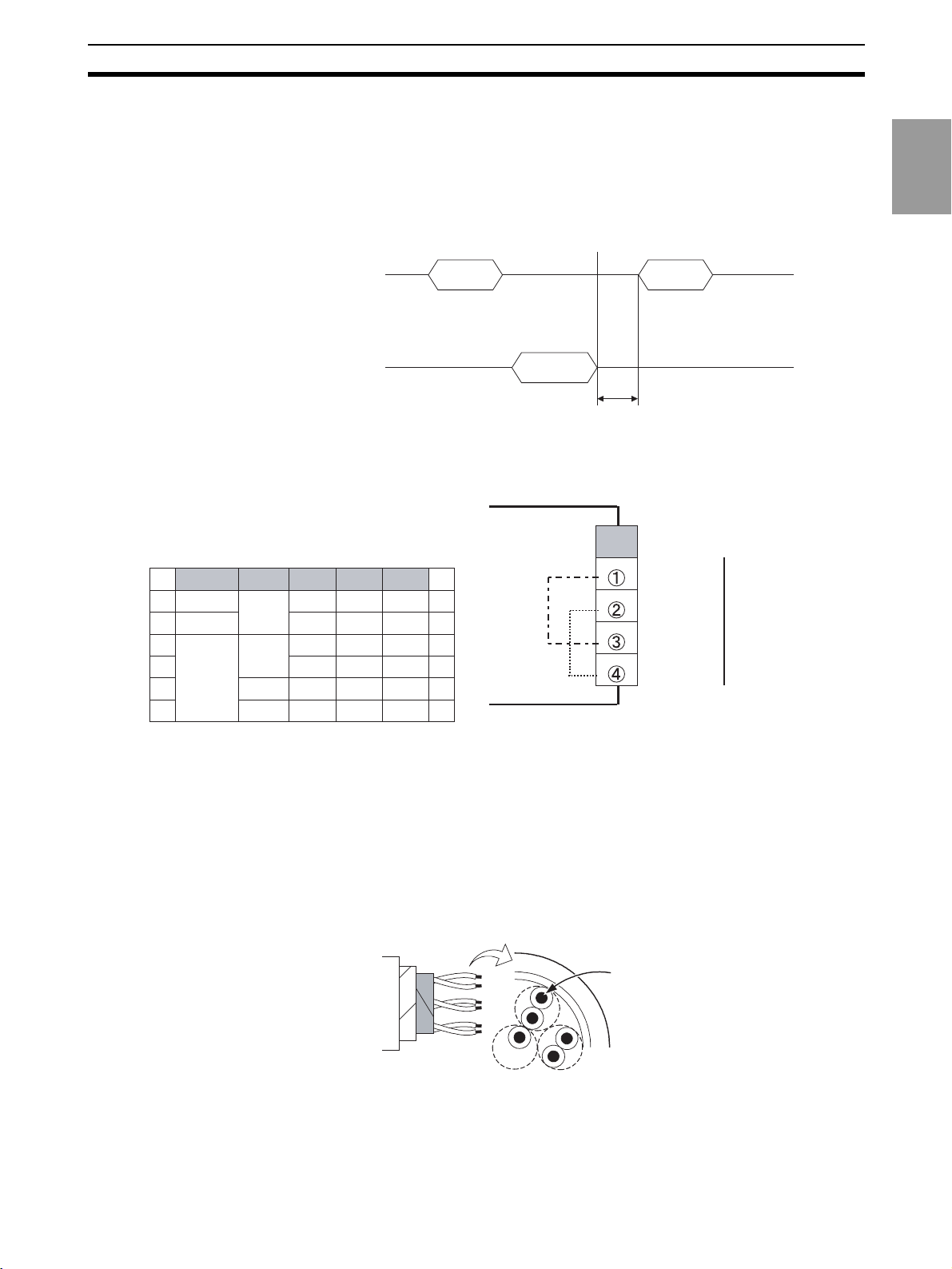
The exchange between the command frame and response frame is explained
below.
After a receiving a response from the Digital Indicator, have the host computer
wait at least 50 ms before sending the next command.
When writing multiple sets of setting data in a row, such as when writing to the
variable area or performing a compound write, controllability may be affected.
Pay attention to the following points:
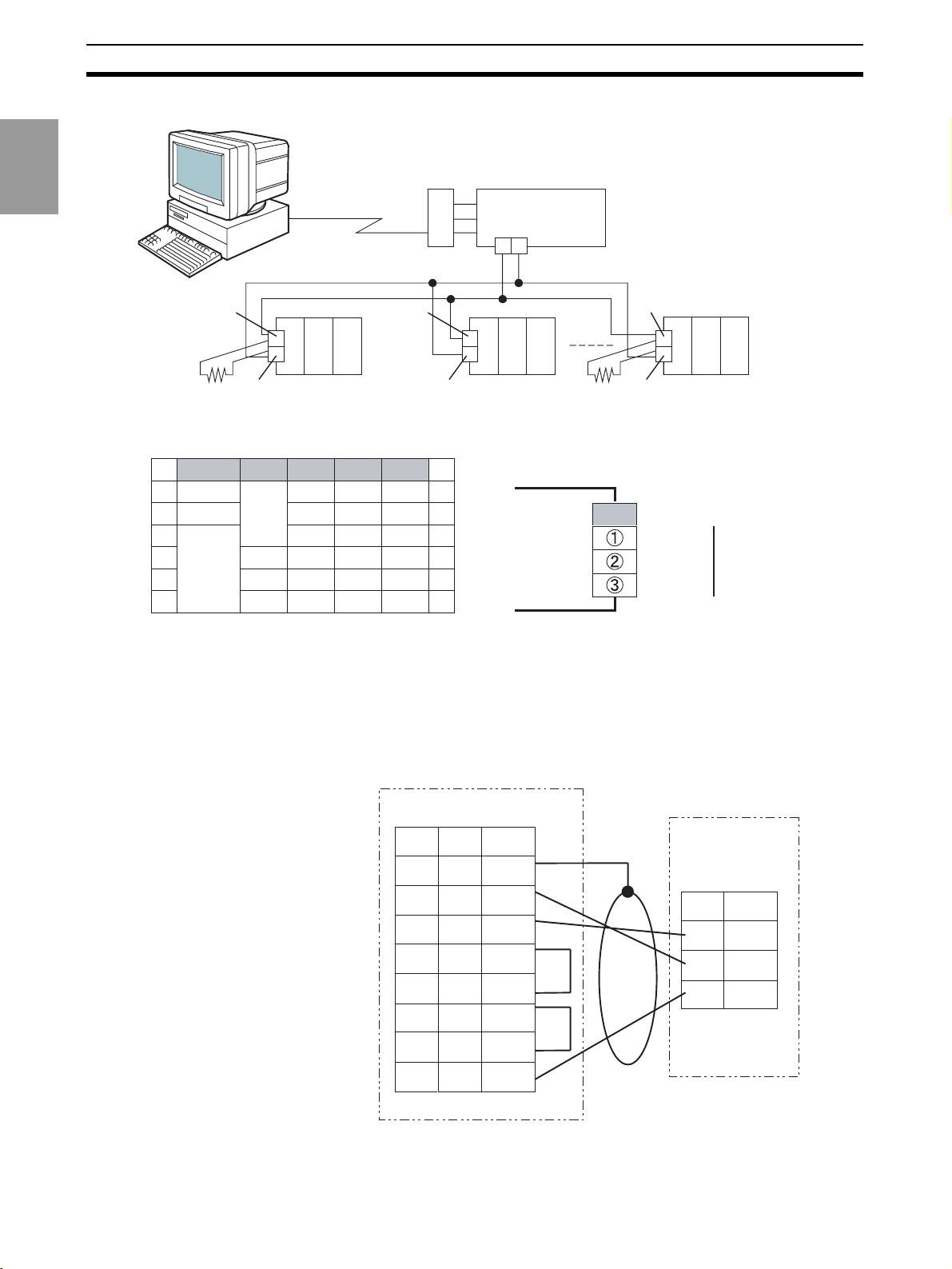
1-1-4 Cable Connections
RS-485
Command
Maximum of 3 sets of
setting data can be written
Response
Command
50 ms or higher
B
Communications
CompoWay/F
A B C D E
1 1
2
3
RS-485
RS-485
4
5
6
• Use terminals B1 through B4 to communicate with the host. The terminal
layout is designed for cross-over wiring and thus the B1-B3 and B2-B4
terminals are connected internally.
• Wiring is configured either 1:1 or 1:N. A maximum of 32 Units, including
the host computer can be connected with a 1:N configuration.
• The maximum total cable length is 500 m.
• Use shielded, twisted-pair wires of at least AWG28 to AWG16 for all
cables.
Cable Diagram (Reference)
B (+)
2
3
4
A (−)
B (+)
A (−)
RS-
485
5
6
At least AWG28
Conductor cross-sectional area:
0.081 mm
2
min.
• Attach a terminator to each end of the transmission path, including the
host computer. Use a 100- to 125-
Ω (1/2 W) resistor for the terminator.
• Use an RS-232C/RS-485 Converter to connect RS-232C devices, such
as personal computers.
1-3
Page 25
Communications Method Section 1-1
Converter Example: RS-232C/RS-485 Converter
K32-23209
Adapter
CompoWay/F
Communications
RS-232C
D-sub, 9-pin
(Straight)
K3SC-10
RS-232C/RS485
Converter
+
-
100- to 125-Ω
Terminator
(1/2 W)
RS-232C
B1 or B3
B2 or B4
(B)
(A)
K3HB
(No. 0)
B1 or B3
B2 or B4
(B)
(A)
K3HB
(No. 1)
B1 or B3
B2 or B4
(B)
(A)
K3-HB
(No. 31)
A B C D E
11
22
33
44
55
RS-232C
B
SD
RD RS-232C
SG
66
• Use terminals B1 through B3 to communicate with the host.
• Wiring is configured 1:1.
• The maximum cable length is 15 m. Use OMRON’s Z3RN RS-232C Optical Interface to extend the wiring path.
• Use shielded, twisted-pair wires of at least AWG28 to AWG16 for all
cables. (Same wire used for RS-485 cable.)
100- to 125-Ω
Terminator
(1/2 W)
1-4
Host computer
RS-232C
9-pin
25-pin
--- FG
1
3SD
2
2RD
3
7RS
4
8CS
5
6DR
6
4ER
20
5SG
7
K3HB
RS-232C
No.
1SD
2RD
3SG
Shield
Page 26
Frames (CompoWay/F Communications) Section 1-2
1-2 Frames (CompoWay/F Communications)
Based on CompoWay/F protocol, commands from the host computer and
responses from the K3HB take the form of frames.
The data comprising command frames and response frames are explained
below.
In the following explanation, an “H” following a numeric value (for example
02H) indicates that the value is a hexadecimal number. A number or letters
enclosed in quotation marks (for example “00”) is an ASCII character.
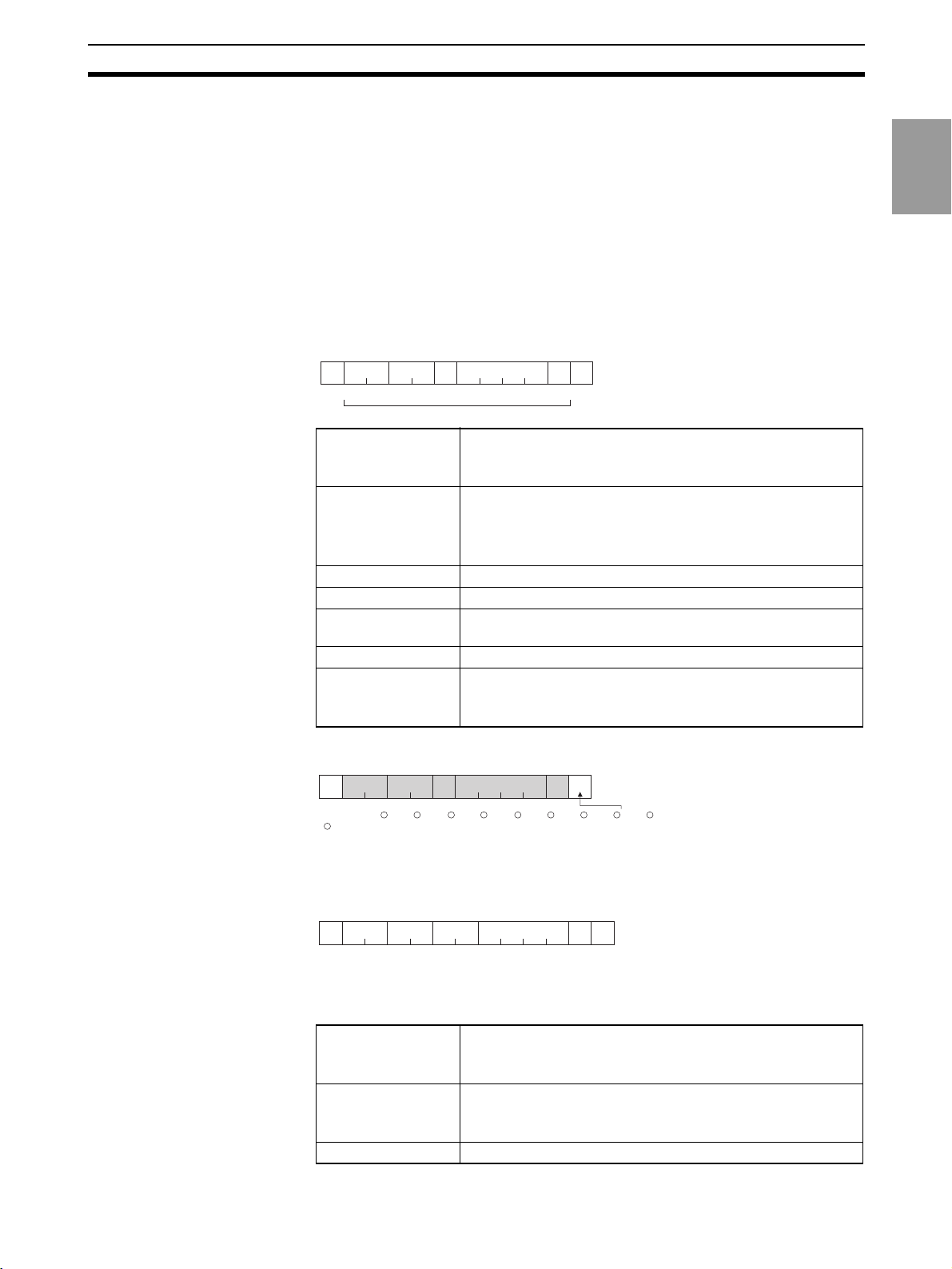
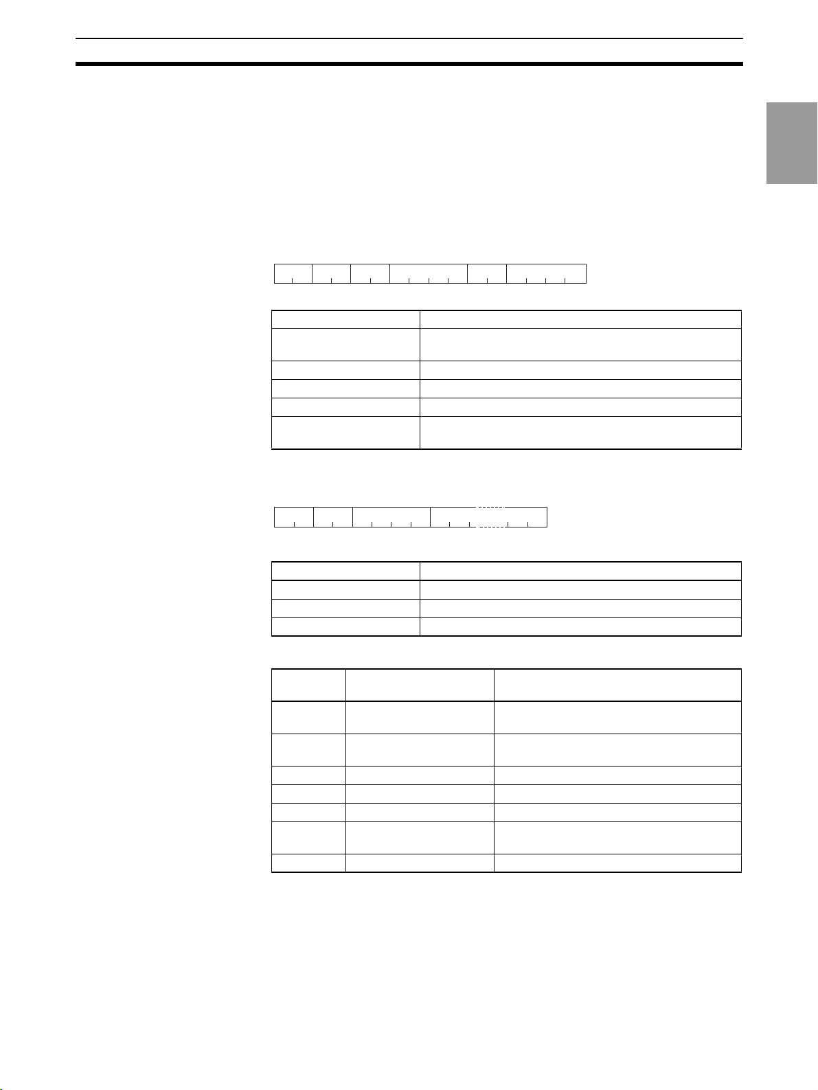
1-2-1 Command Frame
Sub-
Node
address
No.
02H "00" "0"
1
BCC calculation range
STX Code that indicates the beginning of the communications
Node No. This number specifies the destination.
Sub-address Not used on the K3HB. Be sure to set to “00”.
SID (Service ID) Not used on the K3HB. Be sure to set to “0”.
FINS-mini
Command text
ETX Code that indicates the end of the text (03H).
BCC Block Check Character.
FINS-mini
SIDSTX
command text
ETX1BCC
03H
1 byte221
frame (02H).
Be sure to set this code in the leading byte.
Specify the Unit No. of the K3HB.
When broadcasting to all units, specify “XX”. Responses are
not sent to a broadcast.
The text of the command.
This stores the result of the BCC calculation from Node No. to
EXT.
Communications
CompoWay/F
Sub-
Node
address
No.
02H 30H30H 30H30H 30H 30H 35H 30H 30H 03H 36H
BCC = 30H + 30H + 30H + 30H + 30H + 30H + 35H + 30H + 30H + 03H = 36H
+: XOR (exclusive OR) operation
FINS-mini
SIDSTX ETX BCC
command text
1-2-2 Response Frame
Node
Sub-
STX
No.
address
02H "00"
1
End
Code
Supplement A response is not sent to command frames that do not end with ETX.BCC
characters.
STX Code that indicates the beginning of the communications
Node No. The number that was specified in the command frame is
Sub-address Not used on the K3HB. Set to “00”.
FINS-mini
response text
ETX1BCC
03H
1 byte222
frame (02H).
Be sure to set this code in the leading byte.
repeated here.
This is the Unit No. of the responding K3HB.
1-5
Page 27
FINS-mini Text Section 1-3
End code Returns the result of the command executed as instructed by
the command frame.
FINS-mini
Text of the response
Response text
CompoWay/F
Communications
ETX Code that indicates the end of the text (03H)
BCC Block Check Character
Stores the result of the BCC calculation from Node No. to
EXT.
End Codes (CompoWay/F Communications)
End code Name Description Error detection
order of
priority
“0F” FINS command error Could not execute the specified FINS command 8
“10” Parity error Sum of bits that are “1” in received data does not agree with
the set communications parity value.
“11” Framing error Stop bit of command frame characters is “0”. 1
“12” Overrun error Attempted to transfer new data because received data buffer
is already full.
“13” BCC error Calculated BCC different from received BCC. 5
“14” Format error Characters other than “0” to “9” or “A” to “F” in FINS-mini com-
mand text. In the case of an echo-back test, when data other
than the test data is sent.
No SID and FINS-mini command text, or no FINS-mini com-
mand text.
“MRC/SRC” not correct in FINS-mini command text.
“16” Sub-address error No sub-address, SID, or FINS-mini command text; or sub-
address less than 2 characters and no SID and FINS-mini
command text.
“18” Frame length error The received frame exceeds the required number of bytes. 4
“00” Normal end Command was executed normally without error. None
2
3
7
6
1-3 FINS-mini Text
The FINS-mini command text and FINS-mini response text form the body of
command/response communications.
FINS-mini command text and FINS-mini response text are configured as follows.
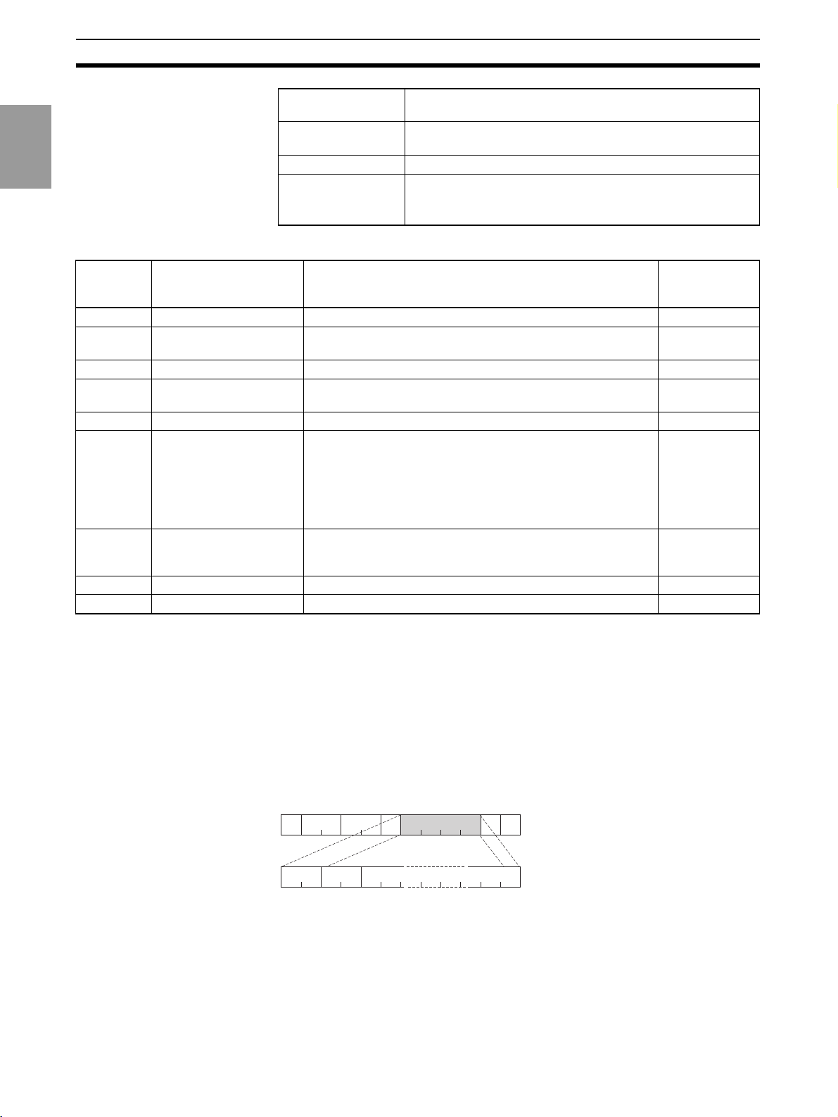
Command Text FINS-mini command text consists of an MRC (main request code) and an
SRC (sub request code), followed by the required data.
Node
Sub-
No.
address
02H "00" "0" 03H
SRC
MRC
2 bytes
2
SIDSTX
command text
FINS-mini
Data
ETX BCC
1-6
Page 28

FINS-mini Text Section 1-3
Response text FINS-mini response text consists of the MRC and SRC, followed by an MRES
(main response code) and SRES (sub response code), and then the required
data.
Node
Sub-
No.
STX
02H "00" 03H
MRC2SRC2MRES
address
2
SRES
2 bytes
FINS-mini
Response textEnd code
ETX BCC
Data
If the specified FINS-mini command was not successfully executed, the
response will only contain the MRC, SRC, MRES and SRES.
List of FINS-mini Service Commands (CompoWay/F Communications)
MRC SRC Service name Description
“01” “01” Monitor value/setting data read Reads monitor values/setting
data.
“01” “02” Monitor value/setting data write Writes monitor values/setting
“01” “04” Monitor value/setting data com-
pound read
“01” “13” Monitor value/setting data com-
pound write
“01” “10” Monitor value/setting data com-
pound stored read
“01” “11” Monitor value/setting data com-
pound read store (write)
“01” “12” Monitor value/setting data com-
pound read store check (read)
“05” “03” Machine attribute read Reads the model and other
“06” “01” Controller status read Reads the operation status.
“08” “01” Echo-back test Performs an echo-back test.
“30” “05” Operation command Commands such as Run/Stop,
data.
Performs multiple reads of moni-
tor values/setting data.
Performs multiple writes of mon-
itor values/setting data.
Sequentially reads contents of
addresses specified in “monitor
value/setting data compound
read store.”
Specifies addresses to be read
using “monitor value/setting data
compound stored read.”
Reads the contents stored using
“variable area compound read
store.”
attributes.
AT Execute/Cancel, and “Move
to setting area 1".
Communications
CompoWay/F
1-7
Page 29
Variable Areas Section 1-4
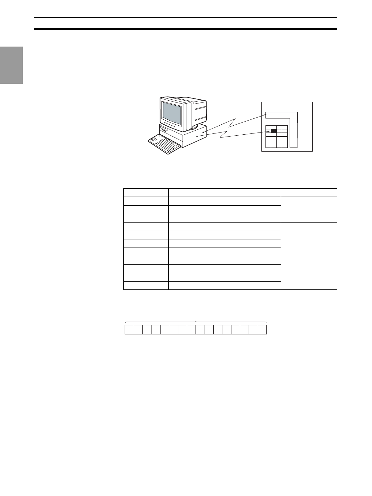
1-4 Variable Areas
The area used for data exchange when communicating with the K3HB is
called the “variable area.” The PV is read and various setting data are read
CompoWay/F
Communications
Variable Types Variable types in variable areas are as follows:
and written using the variable area of the K3HB.
Operation commands and reading of machine attributes do not use the vari-
able area.
K3HB
Operation
commands, etc.
Read/write
Microprocessor
Variable area
A variable area is accessed by specifying the position of a variable within the
variable area using the variable type and address.
Variable type Description Area
C0 Read-only parameters Setting area 0
C1 Protect level
C2 RUN level
C4 Initial setting level Setting area 1
C5 Input adjustment level
C6 Display adjustment level
C7 Scaling level
C8 Comparative set value level
C9 Linear output level
CA Communications setting level
CB Advanced function setting level
(during operation)
(during stop)
Addresses (CompoWay/F
Communications)
Each variable type has an address. Addresses are 2 bytes long and written in
hexadecimal. Addresses are assigned according to units of access size.
Address (2 bytes)
000000##0A6A5A4A3A2A1A
0
For more information on addresses, refer to List of Settings on page 2-1.
Number of Elements The number of elements is expressed as a 2-byte hexadecimal number. The
specification range for the number of elements varies depending on the command. See 1-9 Commands and Responses (CompoWay/F Communications)
(page 1-13) for more information.
For example, if the number of elements is 0010, the first 16 elements of data
(H'10) from the address are specified.
Set Values Values read and written to the variable area are expressed in hexadecimal
and disregard the decimal point position (negative values are expressed as a
two's complement).
Example: D'105.0
→ H'0000041A
The variable is an 8-digit number in hexadecimal. Negative values are expressed as a two's complement. The decimal is disregarded.
1-8
Page 30
Reading the Variable Area Section 1-5
For example, if the PV of the K3HB is 105.0, it will be read as H'0000041A
(105.0
→ 1050 → H'0000041A).
1-5 Reading the Variable Area
The data area is read by setting the required data in the following FINS-mini
command text format.
Command FINS-mini Command Text
MRC SRC
"01" "01" "00"
Variable
type
Data name Explanation
MRC/SRC Specifies the FINS-mini monitor value/setting data read
Variable type Specify a variable type.
First address of read Specify the address for the beginning of the read.
Bit position Not used on the K3HB. Specify “00”.
Number of elements Specifies the number of variables to read (max. of 25
Response FINS-mini Response Text
Response code
SRC
MRC
"01" "01"
2 2 4 Number of elements × 8 bytes
(MRES/SRES)
Read start
address
command.
(H'19)). Not needed for a compound read.
Bit
position
Number of elements
"0001" to "0019"
24222
Data to be read
(for compound read, number of elements × 10 bytes)
4
Communications
CompoWay/F
Data name Explanation
MRC/SRC The FINS-mini command text appears here.
Response code Result of execution of the command.
Read data Values for variables that were read.
Response Codes
Response
code
“1001” Command length too
“1002” Command length too
“1101” Area type error Incorrect variable type.
“110B” Response length too long Number of elements > 25 (H'0019).
“1100” Parameter error Specified bit position is other than “00”.
“2203” Operation error Unit error, unit change, display unit error,
“0000” Normal end
Error name Explanation
The command is too long.
long
The command is too short.
short
internal non-volatile memory error
1-9
Page 31

Writing to the Variable Area Section 1-6
1-6 Writing to the Variable Area
Write to the data area by setting the required data in the following FINS-mini
command text format.
CompoWay/F
Communications
Command FINS-mini Command Text
Variable
SRCMRC
type
"01" "02" "00"
Starting
address
of write
Bit
position
24222
Number of
elements
"0001" to "0018"
4
Write data
Data name Explanation
MRC/SRC Specifies the FINS-mini monitor value/setting data write
command.
Variable type Specify a variable type.
First address of write Specify the address for the beginning of the write.
Bit position Not used on the K3HB. Specify “00”.
Number of elements Specifies the number of variables to be written (max. of
24 (H'18)). Not needed for a compound write.
Write data Enter data to be written.
Response FINS-mini Response Text
Response code
SRCMRC
(MRES/SRES)
"01" "02"
22 4
Data name Explanation
MRC/SRC FINS-mini command text appears here.
Response code Result of execution of the command.
Response Codes
Response
code
“1002” Command length too
“1101” Area type error Incorrect variable type.
“1003” Number of elements/Data
“1100” Parameter error Bit position specification other than “00”.
“2203” Operation error Write via communications is disabled.
“0000” Normal end
Error name Explanation
The command is too short.
short
The specified number of elements does not
number do not agree
agree with the actual number of data elements.
Written data was outside of setting range.
Write to setting area 1 was attempted from
setting area 0.
Write to setting data of protect level was
attempted from other than protect level.
Calibration level in progress.
Unit error, unit change, display unit error,
internal non-volatile memory error.
1-10
Page 32

Operation Commands (CompoWay/F Communications) Section 1-7
1-7 Operation Commands (CompoWay/F Communications)
Operation commands are sent using the following FINS-mini command text
format.
Command FINS-mini Command Text
Instruction
SRCMRC
code
"30" "05"
2222
Data name Explanation
MRC/SRC Specify the FINS-mini operation command.
Operation code Specify an operation code.
Related information Specify information related to the command.
Operation commands for the K3HB are shown in the following table.
Operation code Description Related information
00 Write via communications 00: OFF (Disabled)
01 Reset 00
02 Bank selection 00 to 07: Bank 0 to 7
03 Zero execute/cancel 00: Zero cancel
06
07 Move to setting area 1 00
08 Move to protect level 00
0B Initialize settings 00
Related
information
Software reset
01: ON (Enabled)
01: Zero execute
00
Communications
CompoWay/F
Note A software reset will not respond (no service PDU response).
Response FINS-mini Response Text
Response code
SRCMRC
(MRES/SRES)
"30" "05"
22 4
Data name Explanation
MRC/SRC FINS-mini command text appears here.
Response code Result of execution of the command.
Response Codes
Response
code
“1001” Command length too
“1002” Command length too
“1100” Parameter error Operation code or related information is not
Error name Explanation
long
short
The command is too long.
The command is too short.
correct.
1-11
Page 33

Setting Areas Section 1-8
Response
code
“2203” Operation error Unable to execute because write via com-
CompoWay/F
Communications
“0000” Normal end
Error name Explanation
munications is disabled.
Unable to execute operation command. For
more information, see corresponding operation command explanation in 1-9 Com-
mands and Responses (CompoWay/F
Communications).
Unit error, unit change, display unit error,
internal non-volatile memory error
1-8 Setting Areas
The K3HB has two setting areas for communications: Setting area 0 and setting area 1.
In setting area 0, control continues.
As such, setting area 0 makes it possible to perform operations that require
control to be in progress, such as reading the PV, writing an SP, and run/stop,
as well as operations that do not interfere with control. On the other hand,
operations that may change control such as writing initial setting data cannot
be performed. (Note that setting data that cannot be written can still be read.)
In setting area 1, control is stopped.
This makes it possible to perform operations such as writing initial setting data
which are not possible in setting area 0.
When the power is turned on, setting area 0 is selected. To access setting
area 1, use the “Move to setting area 1” operation command. To return to setting area 0 from setting area 1, turn off the power or use the “Software reset”
operation command.
Power on
Setting area 0
Control in progress
Variable type Description Area
C0 Read-only parameters Setting area 0 (during control)
C1 Protect level
C2 RUN level
C4 Initial setting level Setting area 1 (during stop)
C5 Input adjustment level
C6 Display adjustment level
C7 Scaling level
C8 Comparative set value level
C9 Linear output level
CA Communications setting level
CB Advanced function setting
level
"Software reset" command
"Move to setting
area 1" command
Setting area 1
Control stop
1-12
Page 34

Commands and Responses (CompoWay/F Communications) Section 1-9
1-9 Commands and Responses (CompoWay/F
Communications)
The K3HB provides a set of applied commands that make use of variable area
read/write commands, operation commands, and other services provided by
the CompoWay/F communications protocol.
K3HB applied commands are explained below.
1-9-1 Monitor Value Read (CompoWay/F Communications)
Command
MRC SRC
"01" "01" "0001""00"
Variable
type
Address
Variable type Address Monitor value (data name)
“C0” “0000” Version
“0001” Status
“0002” Measurement value
“0003” Maximum value
“0004” Minimum value
This command is used to read the PV, status, and other monitor values. The
number of elements can be set from 0002 to 0019 to allow reading of monitor
values in contiguous addresses.
Bit
position
Number of
elements
Communications
CompoWay/F
Response
MRC SRC Response code
"01" "01" "0000" Monitor value
Data
Response codes: The above indicates a normal end. For the response codes,
see 1-5 Reading the Variable Area (page 1-9).
1-9-2 Setting Data Read (CompoWay/F Communications)
Command
MRC SRC
"01" "01" "00"
Variable
type
Address
Variable type Address Setting data (explanation)
“C1”
“0000” to “0004” Setting data of setting area 0
“C2”
“0000” to “0027” Setting data of setting area 1
“C4”
“C5”
“C6”
“C7”
“C8”
“C9”
“CA”
“CB”
Bit
position
Number of
elements
"0001"
Protect level
RUN level
Initial setting level
Input adjustment level
Display adjustment level
Scaling level
Comparison setting
Linear output setting level
Communications setting level
Advanced function setting level
This command is used to read setting data. The number of elements can be
set from 0002 to 0019 to allow successive reading of 2 to 25 items of setting
data in contiguous addresses.
1-13
Page 35

Commands and Responses (CompoWay/F Communications) Section 1-9
To specify the variable type or address, see SECTION 2 List of Settings
(page 2-1). The upper limit of an address will vary depending on the variable
type.
This command can be used in both setting area 0 and setting area 1.
CompoWay/F
Communications
Response
MRC SRC
"01" "01"
Response code
"0000"
Data
Setting data
Response codes: The above indicates a normal end. For the response codes,
see 1-5 Reading the Variable Area (page 1-9).
1-9-3 Monitor Value/Setting Data Compound Read (CompoWay/F
Communications)
Command
MRC SRC
"01" "04" "00"
Variable
type
Bit positionAddress
Variable type Address Setting data (explanation)
“C0” “0000” to “0004” Monitor values
“C1” to “C2” “0000” to “0004” Setting data of setting area 0
“C4” to “CB” “0000” to “0027” Setting data of setting area 1
Multiple monitor values or setting data can be read by sending a single command. Up to 20 items can be read even if the addresses are not contiguous.
To specify the variable type or address, see SECTION 2 List of Settings
(page 2-1). The upper limit of an address will vary depending on the variable
type.
This command can be used in both setting area 0 and setting area 1.
If an area type error or a setting data error occurs in any of the data being
read, no data will be read.
Variable
type
Address
AddressVariable type
Bit position
"00"
Bit position
"00"
Response
1-14
Variable
MRC SRC Response code Data
"01" "04" "0000"
type
Type
Monitor value / Setting data
Variable type Data
Type Monitor value / Setting data
Response codes: The above indicates a normal end. For the response codes,
see 1-5 Reading the Variable Area (page 1-9).
Page 36

Commands and Responses (CompoWay/F Communications) Section 1-9
1-9-4 Protect Level Setting Data Write
Command
Variable
type
SRCMRC
"01" "02" "C5" "00" "0001" Protect level setting data
Address Setting data
“0000” Operation adjustment protect
“0001” Setting level protect
“0002” Setting change protect
“0003” Forced zero protect
“0004” MAX/MIN protect
This command writes protect level setting data.
This command is used in setting area 0. An error will result if used in setting
area 1.
To use this command, use the “Write via communications” operation com-
mand to enable “Write via communications,” and then use the “Move to protect level” operation command to move to “Protect level.”
Response
SRCMRC
"01" "02" "0000"
Response codes: The above indicates a normal end. For the response codes,
see 1-6 Writing to the Variable Area (page 1-10).
Address
Response code
Bit position
Number of
elements
Data
Communications
CompoWay/F
1-9-5 Setting Data Write (CompoWay/F Communications)
Command
Variable
type
SRCMRC
"01" "02" "00" "0001"
Address
Bit position
Variable type Address Setting data (explanation)
“C1”
“0000” to “0004” Setting data of setting area 0
“C2”
“C4”
“0000” to “0027” Setting data of setting area 1
“C5”
“C6”
“C7”
“C8”
“C9”
“CA”
“CB”
The above setting data is written. The number of elements can be set from 2
to 24 to write setting data of contiguous addresses.
To specify an address, see SECTION 2 List of Settings (page 2-1).
Setting data of setting area 1 can be written in setting area 1. An error will
result if written in setting area 0.
To use this command, “Write via communications” must be enabled using the
“Write via communications” operation command.
Number of
elements
Setting data
Protect level
RUN level
Initial setting level
Input adjustment level
Scaling level
Display adjustment level
Comparison setting
Linear output setting level
Communications setting level
Advanced function setting level
Data
1-15
Page 37

Commands and Responses (CompoWay/F Communications) Section 1-9
Response
SRCMRC
Response code
"01" "02" "0000"
Response codes: The above indicates a normal end. For the response codes,
CompoWay/F
Communications
see 1-6 Writing to the Variable Area (page 1-10).
1-9-6 Setting Data Compound Write (CompoWay/F Communications)
Command
Variable
type
"01" "13" "00"
AddressMRC SRC
Bit position
Data
Setting data
AddressVariable type
Bit position
"00"
Data
Setting data
Variable type Address Setting data (explanation)
“C1” to “C2” “0000” to “0004” Setting data of setting area 0
“C4” to “CB” “0000” to “0027” Setting data of setting area 1
Multiple setting data items can be written by sending a single command. Up to
12 items can be written even if the addresses are not contiguous.
To specify the variable type or address, see SECTION 2 List of Settings
(page 2-1).
Setting data of setting area 1 is written in setting area 1. An error will result if
written in setting area 0.
To use this command, “Write via communications” must be enabled using the
“Write via communications” operation command.
Response
SRCMRC
Response code
"01" "13" "0000"
Response codes: The above indicates a normal end. For the response codes,
see 1-6 Writing to the Variable Area (page 1-10).
1-9-7 Monitor Value/Setting Data Compound Read Store (Write)
Command
1-16
Variable
"01" "11" "00"
type
Read address
Bit position
Variable
type
Variable
type
Read addressMRC SRC
Read address
Bit position
"00"
Bit position
"00"
Variable type Address Setting data (explanation)
“C0” “0000” to “0004” Monitor values
“C1” to “C2” “0000” to “0004” Setting data of setting area 0
“C4” to “CB” “0000” to “0027” Setting data of setting area 1
This command is used to store the addresses of multiple monitor values or
setting data that you wish to read.
The stored monitor values or setting data can be read by sending a single
“Monitor value/setting data compound store read” command. Up to 20 items
can be stored, even if the addresses are not continuous.
Page 38

Commands and Responses (CompoWay/F Communications) Section 1-9
To specify the variable type or address, see SECTION 2 List of Settings
(page 2-1). The upper limit of an address will vary depending on the variable
type.
This command can be used in both setting area 0 and setting area 1.
Response
SRCMRC
Response code
"01" "11" "0000"
Response codes: The above indicates a normal end. For the response codes,
see 1-5 Reading the Variable Area (page 1-9).
1-9-8 Monitor Value/Setting Data Compound Read Store Check (Read)
Command
SRCMRC
"01" "12"
This is used to check the contents that were stored using “Monitor value/setting data compound read store.”
Response
Variable
Response code
"01" "12" "0000"
type
Type
Variable
type
Type
Read addressMRC SRC
Read address
Bit position
"00"
Communications
CompoWay/F
Response codes: The above indicates a normal end. For the response codes,
see 1-5 Reading the Variable Area (page 1-9).
1-9-9 Monitor Value/Setting Data Compound Store Read
Command
SRCMRC
"01" "10"
This is used to read by a single command the multiple monitor values or setting data items that were stored using “Monitor value/setting data compound
read store (write).”
This command can be used in both setting area 0 and setting area 1.
If an area type error or a setting data error occurs in any of the data being
read, no data will be read.
Response
Variable
MRC SRC
"01" "10" "0000"
Response code
Response codes: The above indicates a normal end. For the response codes,
see 1-5 Reading the Variable Area (page 1-9).
type
Type
Variable type
Type
Data
Monitor value / Setting data
Data
Monitor value / Setting data
1-17
Page 39

Commands and Responses (CompoWay/F Communications) Section 1-9
1-9-10 Write via Communications
Command
Command
SRC
MRC
CompoWay/F
Communications
"30" "05"
Related information Description
“00” Write via communications disabled
“01” Write via communications enabled
This command is used to enable or disable “Write via communications.” When
sent, it changes the set value of “Write via communications.”
When write via communications is disabled, communications cannot be used
to write setting data or send operation commands.
The initial setting is “disabled.”
This command can be used in both setting area 0 and setting area 1.
Response
SRCMRC
"30" "05" "0000"
Response codes: The above indicates a normal end. For the response codes,
see 1-7 Operation Commands (CompoWay/F Communications) (page 1-11).
Related
information
code
"00"
Response code
1-9-11 Reset
Command
Response
1-9-12 Bank Selection
Command
code
"01"
Related
information
SRC
MRC
"30" "05"
Command
Related information Description
“00” Reset
This command resets the system to no-measurement status. It can only be
used in setting area 0.
SRCMRC
Response code
"30" "05" "0000"
Response codes: The above indicates a normal end. For the response codes,
see 1-7 Operation Commands (CompoWay/F Communications) (page 1-11).
Command
SRC
MRC
"30" "05"
Related information Bank No. selected
“00” to “07” 0 to 7
code
"02"
Related
information
1-18
This command can be used only when “Bank Selection” is set to “Key.”
This command is used to change between comparative set values preset in
banks. There are 8 banks numbered 0 to 7.
This command can be used in both setting area 0 and setting area 1.
Page 40

Commands and Responses (CompoWay/F Communications) Section 1-9
Response
"30" "05" "0000"
Response codes: The above indicates a normal end. For the response codes,
see 1-7 Operation Commands (CompoWay/F Communications) (page 1-11).
1-9-13 Zero Execute/Cancel
Command
MRC
"30" "05"
Related information Description
“00” Zero cancel
“01” Zero execute
This command is used to execute/cancel the forced zero and tare zero functions. The results of the command will depend on the status of the tare zero
setting, as shown below.
Tare
zero
OFF Forced zero ON Forced zero ON Forced zero OFF Forced zero OFF
ON Forced zero ON Tare zero ON Tare zero OFF Forced zero OFF
SRCMRC
Response code
SRC
Command
code
"03"
Related
information
Commands executed in order left to right.
Zero execute Zero execute Zero cancel Zero cancel
Communications
CompoWay/F
Response
1-9-14 Software Reset
Command
This command can be used only in setting area 0. An operation error will
occur in the following situations.
• When there is no-measurement status, there is an input error, or a measurement is outside the display range (but zero cancel is possible.)
• When a RESET or HOLD input is ON
• When the command is used in setting area 1
SRCMRC
Response code
"30" "05" "0000"
Response codes: The above indicates a normal end. For the response codes,
see 1-7 Operation Commands (CompoWay/F Communications) (page 1-11).
SRC
MRC
"30" "05"
Command
code
information
"06" "00"
Related
A software reset causes the same operation as turning the power off and on.
This command can be used in both setting area 0 and setting area 1.
To use this command, “Write via communications” must be enabled using the
“Write via communications” operation command.
Response (No response)
A response is not returned to this operation command.
1-19
Page 41

Commands and Responses (CompoWay/F Communications) Section 1-9
1-9-15 Move to Setting Area 1
Command
Command
SRC
MRC
CompoWay/F
Communications
"30" "05"
code
information
"07" "00"
Related
Use this command to move to setting area 1.
The command is used in setting area 0. Nothing happens if the command is
used in setting area 1.
If the command is used when “Initial setting protect” is set to 2 (Disable move
to input initial setting level), an operation error will result.
To use this command, “Write via communications” must be enabled using the
“Write via communications” operation command.
Response
SRCMRC
Response code
"30" "05" "0000"
Response codes: The above indicates a normal end. For the response codes,
see 1-7 Operation Commands (CompoWay/F Communications) (page 1-11).
1-9-16 Move to Protect Level
Command
MRC
"30" "05"
Use this command to move to protect level.
This command is used in setting area 0. If used in setting area 1, an operation
error will result.
To use this command, “Write via communications” must be enabled using the
“Write via communications” operation command.
Response
"30" "05" "0000"
Response codes: The above indicates a normal end. For the response codes,
see 1-7 Operation Commands (CompoWay/F Communications) (page 1-11).
1-9-17 Initialize Settings
Command
MRC
"30" "05"
This returns all settings to the initial settings.
This command is used in setting area 1. If used in setting area 0, an operation
error will result.
To use this command, “Write via communications” must be enabled using the
“Write via communications” operation command.
SRC
SRCMRC
SRC
Command
code
information
"08" "00"
Response code
Command
code
information
"0B" "00"
Related
Related
1-20
Page 42

Commands and Responses (CompoWay/F Communications) Section 1-9
Response
SRCMRC
"30" "05" "0000"
Response codes: The above indicates a normal end. For the response codes,
see 1-7 Operation Commands (CompoWay/F Communications) (page 1-11).
1-9-18 Read Machine Attributes
Command
SRCMRC
"05" "03"
This command reads the K3HB model and communications buffer size.
The command can be used in any state of the K3HB.
Response
"05" "03" "0000" "00D9"
Response codes: The above indicates a normal end. For the response codes,
see 1-7 Operation Commands (CompoWay/F Communications) (page 1-11).
Model
3
H
∗Bytes 8 and 9 are blank
Response code
B-K
Communications
CompoWay/F
Buffer sizeFormatResponse codeSRCMRC
AB
Symbol Series Symbol Input
X Analog input VD DC voltage
AD AC voltage
VA DC current
AA AC current
V mV input LC mV
S Linear Sensor input SD Linear Sensor
H Temperature input TA Temperature
R Rotary pulse input NB NPN/voltage pulse input
PB PNP input
P Time interval input NB NPN/voltage pulse input
PB PNP input
C Up/Down counting pulse
input
NB NPN/voltage pulse input
PB PNP input
1-9-19 Controller Status Read (CompoWay/F Communications)
Command
SRCMRC
"06" "01"
This command reads the operation state of the K3HB.
The command can be used in any state of the K3HB.
Response
MRC SRC Response code
"06" "01" "0000"
Operation
state
Related information
1-21
Page 43

Commands and Responses (CompoWay/F Communications) Section 1-9
Response codes: The above indicates a normal end. For the response codes,
see 1-7 Operation Commands (CompoWay/F Communications) (page 1-11).
Operation State
Operation state Description
CompoWay/F
Communications
Note Measurements outside the display range and no-measurement status do not
00 Operating (no errors in setting area 0, see note)
01 Stopped (all other situations)
generate errors and thus may be possible even for an operation state of 00.
Related Information
Bit position Status
7 Not used
6 Not used
5 Not used
4 Not used
3 Input error B Present value
2 Input error A
1 Measurement outside the dis-
play range
0 No-measurement status
Note (1) The bit will be ON (1) or when an error occurs and otherwise will be OFF
1-9-20 Echo Back Test
Command
This command is used to perform an echo back test.
The command can be used in any state of the K3HB.
Keep the test data within the following ranges depending on the communica-
tions data length.
Response
Response codes: The above indicates a normal end. For the response codes,
see 1-7 Operation Commands (CompoWay/F Communications) (page 1-11).
(0).
(2) Information is in the same order as status information.
SRC
MRC
"08" "01" 0 to 200 bytes
Communications data
7 bits ASCII code H'20 to H'7E
8 bits ASCII code H'20 to H'7E or H'A1 to H'FE
MRC
"08" "01" "0000" 0 to 200 bytes
length
SRC
Test data
Description
Test dataResponse code
1-22
Page 44

Program Example Section 1-10
1-10 Program Example
N88Basic This program displays the response from the K3HB on the screen when com-
mand data is entered from the keyboard.
Command data from the unit number to the number of elements must be
entered.
The program was created in N88BASIC.
1000
'----------------------------------------------------
1010
'PROGRAM: E5AR/ER Communication Sample Program(CompoWay/F)
1020
'VERSION:1.00
1030
(c)Copyright OMRON Corporation 2003
1040
All Rights Reserved
1050
'----------------------------------------------------
1060
'
1070
'======Communication port (PARITY=EVEN, DATA=7, STOP=2) ======"
1080
'
1090
OPEN "COM:E73" AS #1
1100
'
1110
∗SENDDATA
1120
'
1130
========= Communication routine==================
1140
'
1150
--------Communication data input----------
1160
INPUT "SEND DATA:",SEND$
1170
'
1180
--------If no input, jump to end routine----------
1190
IF SEND$ = " " THEN ∗EXITSEND
1200
'
1210
-------BCC calculation--------
1220
BCC = 0
1230
SEND$ = SEND$+CHR$(3)
1240
FOR I=1 TO LEN(SEND$)
1250
BCC = BCC XOR ASC(MID$(SEND$, I, 1))
1260
NEXT I
1270
BCC$ = CHR$(BCC)
1280
'
1290
------Send----------
1300
SDATA$ = CHR$(2)+SEND$+BCC$
1310
PRINT #1, SDATA$;
1320
'
1330
========= Receive routine ===========
1340
'
1350
RDATA$ = " "
1360
TIMEOUT = 0
1370
∗RCVLOOP
1380
-------No response detection-------
1390
TIMEOUT = TIMEOUT+1
1400
IF TIMEOUT > 2000 THEN RESP$ = "No Response":GOTO ∗RCVEND
1410
IF LOC(1) = 0 THEN ∗RCVLOOP
1420
'
1430
-----Check for end character (if no end character, continue reading)
1440
RDATA$ = RDATA$+INPUT$(LOC(1),#1)
1450
IF LEN(RDATA$) <2 THEN ∗RCVLOOP
1460
IF MID$(RDATA$,LEN(RDATA$)-1,1) <> CHR$(3) THEN ∗RCVLOOP
1470
RESP$ = MID$(RDATA$,2,LEN(RDATA$)-2)
1480
∗RCVEND
1490
'
1500
-------Display received data-----------
1510
PRINT "RESPONSE:";RESP$
1520
GOTO ∗SENDDATA
1530
'
1540
∗EXITSEND
1550
=========End routine==========
1560
CLOSE #1
1570
END
Communications
CompoWay/F
1-23
Page 45

Program Example Section 1-10
Operation Example Reading the present value of Unit No.01.
RUN
SEND DATA:010000101C00002000001
RESPONSE:010000010100000000014F
CompoWay/F
Communications
SEND DATA: [STX] 01 00 0 0101 C0 0002 00 0001 [ETX] [BCC]
Number of elements
Bit position
Read start address
Variable type
MRC/SRC
SID
Sub-address
Node No.
RESPONSE: [STX] 01 00 00 0101 0000 0000014F [ETX] [BCC]
Data to be read
Response code
MRC/SRC
End code
Sub-address
Node No.
1-24
Page 46

SECTION 2
List of Settings
This list of settings shows addresses for CompoWay/F communications. Refer to the address for the communications protocol that is used.
Settings
List of
2-1
Page 47

List of Settings Section 2
0 (OFF)
1 (ON)
Status (K3HB)
Output MAX value MIN value
11 12 13 14 15 16
Present value
0 1 2 3 4 5 6 7 8 9 10
Bit position
List of
Settings
Operation status Control inputs Control inputs Outputs
0 0
No measurement status
Measurement outside the
display range
Input error A
Input error B
No measurement status
Measurement outside the
display range
Input error A
Input error B
No measurement status
Measurement outside the
display range
Input error A
Input error B
Comparative set value LL (1)
Comparative set value L (2)
Comparative set value PASS (3)
Comparative set value H (4)
15
16171819202122232425262728293031
Bit position
Comparative set value HH (5)
Error output
Not used
Not used
TIMING
BANK 1
BANK 2
BANK 4
ZERO/COMPENSATION
RESET
HOLD
S-TMR
Setting area
Write via communications
Forced zero
Tare zero
Status
Status
0 (OFF)
No Error
No Error
No Error
No Error
No Error
No Error
No Error
No Error
No Error
No Error
No Error
No Error
OFF ON
OFF
OFF ON
OFF ON
0 (OFF)
1 (ON)
Error
Error
Error
Error
Error
Error
Error
Error
Error
Error
Error
Error
1 (ON)
OFF ON
OFF
OFF
OFF
OFF
OFF
OFF
OFF ON
OFF ON
OFF ON
OFF ON
OFF ON
Setting Area 0
OFF (Disabled)
Setting Area 1
ON (Enabled)
OFF ON
OFF ON
ON
ON
---
---
ON
ON
ON
Note The output status turns ON and OFF whether or not an Output Unit is mounted. The output status is
undefined if there is no output terminal when Unit 3 outputs a two-relay comparative output pattern. If
the output is a two-relay plus one-relay comparative output pattern, LL turns ON when PASS turns ON
(output and display colors are not changed in communications status). A 5-output judgement is performed internally regardless of the number of output points. The LL output is always ON in the above
configuration so the PASS output does not turn ON. To avoid this situation, the HH/LL status is ignored
when Unit 3 uses a two-relay output pattern. The PASS judgement is performed with just H and L for
operations like that described.
2-2
Page 48

List of Settings Section 2
Communications Monitoring Settings
Var iabl e
C0 0000 Version --- --- --- --- --- ---
Note The values beginning with H’ in the Monitor/Setting range column are used when setting or monitoring
Protect Level
Var iabl e
C1 0000 RUN/Adjust-
Address Setting data Character Monitor/Setting range Character Default
type
0001 Status --- --- --- --- --- ---
0002 Measurement
0003 MAX value --- H’FFFFB1E1 to
0004 MIN value --- H’FFFFB1E1 to
value
--- H’FFFFB1E1 to
H’0001869F
−19,999 to 99,999)
(
H’0001869F
−19,999 to 99,999)
(
H’0001869F
−19,999 to 99,999)
(
--- --- --- ---
--- --- --- ---
--- --- --- ---
setting
data via communications.
Address Parameter
type
0001 Setting level
0002 Setting change
0003 Forced zero
0004 MAX/MIN pro-
name
ment protect
protect
protect
protect
tect
Character Monitor/Setting range Character Default
run.pt H’00000000 to
H’00000002: (0 to 2)
set.pt H’00000000 to
H’00000002: (0 to 2)
wt.pt H’00000000: OFF(0)
H’00000001: ON(1)
zr.pt H’00000000: OFF(0)
H’00000001: ON(1)
mm.pt H’00000000 to
H’00000002: (0 to 2)
0 to 20 --- ---
0 to 21 --- ---
off, on off --- ---
off, on off --- --- x
0 to 20 --- ---
setting
Decimal
point
Decimal
point
Unit Model
XVSH
Unit Model
XVSH
Settings
List of
Note The values beginning with H’ in the Monitor/Setting range column are used when setting or monitoring
data via communications.
RUN Level
Var iabl e
C2 0000 Comparative
Address Parameter
type
0001 Comparative
0002 Comparative
0003 Comparative
name
set value HH
set value H
set value L
set value LL
Character Monitor/Setting range Character Default
--- H’FFFFB1E1 to H’0001869F
--- H’FFFFB1E1 to H’0001869F
--- H’FFFFB1E1 to H’0001869F
--- H’FFFFB1E1 to H’0001869F
(
−19,999 to 99,999)
(
−19,999 to 99,999)
−19,999 to 99,999)
(
−19,999 to 99,999)
(
:9999 to
99999
:9999 to
99999
:9999 to
99999
:9999 to
99999
setting
99999 According to
99999 According to
:9999 According to
:9999 According to
Decimal
point
the decimal
position setting
the decimal
position setting
the decimal
position setting
the decimal
position setting
Unit Model
XVSH
---
---
---
---
Note The values beginning with H’ in the Monitor/Setting range column are used when setting or monitoring
data via communications.
2-3
Page 49

List of
List of Settings Section 2
Initial Setting Level
Variable
C4 0000 Calculation cal H’00000000: A(0), H’00000001:B(1),
Settings
Address Parameter
type
name
0001 Input type A in-ta X(VD):
0002 Power sup-
0003 Scaling
0004 Scaling dis-
ply frequency
input value
A1
play value
A1
Char-
acter
Monitor/Setting range Character Default
H’00000002:K-A(2), H’00000003:
A+B(3),
H’00000004: A-B(4), H’00000005: K
(A+B)(5), H’00000000: B/A×10000(6),
H’00000007: (B/A
H’00000000:
H’00000001:
H’00000002:
H’00000003: 1.0000 to 5.0000 V(3)
X(AD):
H’00000000:
H’00000001:
H’00000002:
H’00000003: 4.000 to 20.000 mA(3)
X(VA):
H’00000000: 0.0 to 400.0 V(0),
H’00000001: 0.00 to 199.99 V(1),
H’00000002: 0.000 o 19.999 V(2),
H’00000003: 0.0000 to 1.9999 V(3)
X(AA):
H’00000000: 0.000 to 10.000 A(0),
H’00000001: 0.0000 to 1.9999 A(1),
H’00000002: 0.00 to 199.99 mA(2),
H’00000003: 0.000 to 19.999 m(3)
V:
H’00000000: 0.00 to 199.99 mV(0),
H’00000001: 0.000 to 19.999 mV(1),
H’00000002:
H’00000003:
S:
H’00000000: 0 to 20 mA(0)
H’00000001: 4 to 20 mA(1),
H’00000002: 0 to 5 V(2),
H’00000003: 1 to 5 V(3),
H’00000004:
H’00000005:
H:
H’00000000: 0-Pt100(0), H’00000001:
1-Pt100(1), H’00000002: 2-K(2),
H’00000003: 3-K(3), H’00000004: 4J(4), H’00000005: 5-J(5), H’00000006:
6-T(6), H’00000007: 7-E(7),
H’00000008: 8-L(8), H’00000009: 9V(9), H’0000000A: 10-N(10),
H’0000000B: 11-R(11), H’0000000C:
12-S(12), H’0000000D: 13-B(13),
H’0000000E: 14-W(14)
−1) × 10000(7)
±199.99 V(0),
±19.999 V(1),
±1.9999 V(2),
±199.99 mA(0),
±19.999 mA(1),
±1.9999 mA(2),
±100.00 mV(2),
±199.99 mV(3)
±5 V(4),
±10 V(5)
0, 1, 2, 3, 4,
5, 6, 7
−
X(VD):
a vd, b vd,
c vd, d vd
X(AD):
a ad, b ad,
c ad, d ad
X(VA):
a va, b va,
c va, d va
X(AA):
a aa, b aa,
c aa, d aa
V:
a lc, b lc,
c lc, d lc
S:
0-20, 4-20,
0-5, 1-5, 5,
10
H:
0-pt, 1-pt,
2-k, 3-k, 4j, 5-j, 6-t,
7-e, 8-l, 9u, 10-n, 11r, 12-s, 13b, 14-w
setting
Decimal
point
Unit Model
0 --- --- x x x
X(VD): a vd
X(AD): a ad
X(VA): a va
X(AA): a aa
V: a lc
S: 4 to 20
H: 2-k
--- ---
fre H’00000000: 50(0), H’00000001: 60(1) 50, 60 50 --- Hz x
. a1 H’FFFFB1E1 to H’0001869F
inp
dsp
−19,999 to 99,999)
(
. a1 H’FFFFB1E1 to H’0001869F
−19,999 to 99,999)
(
:9999 to
99999
:9999 to
99999
X (VD):
:99 . 99
X (AD):
:99 . 99
X (VA): 0
X (AA):
0 . 000
. 00
V: 0
S: 4
. 000
X (VD):
:9999
X (AD):
:9999
X (VA): 0
X (AA): 0
V: 0
S: 4000
. 0
According to the
input type
According to
the
input
type
--- --- x
XVSH
x
2-4
Page 50

List of Settings Section 2
Variable
C4 0005 Scaling
Address Parameter
type
0006 Scaling dis-
name
input value
A2
play value
A2
0007 Input type B in-tb H’00000000: 0 to 20 mA(0),
0008 Scaling
0009 Scaling dis-
000A Scaling
000B Scaling dis-
input value
B1
play value
B1
input value
B2
play value
B2
000C Constant K k H’FFFFB1E1 to H’0001869F (
000D Decimal
000F Tempera-
000E Compara-
point position
ture units
tive output
pattern
Char-
acter
inp . a2 H’FFFFB1E1 to H’0001869F (−19,999
. a2 H’FFFFB1E1 to H’0001869F (−19,999
dsp
inp.b1 H’FFFFB1E1 to H’0001869F (
dsp.b1 H’FFFFB1E1 to H’0001869F (
inp.b2 H’FFFFB1E1 to H’0001869F (
dsp.b2 H’FFFFB1E1 to H’0001869F (
dp H’00000000 to
d-u H’00000000
out-p H’00000000: standard output(0),
Monitor/Setting range Character Default
to 99,999)
to 99,999)
H’00000001: 4 to 20 mA(1),
H’00000002: 0 to 5 V(2), H’00000003:
1 to 5 V(3), H’00000004:
H’00000005:
±10(5)
to 99,999)
to 99,999)
to 99,999)
to 99,999)
to 99,999)
±5 V(4),
−19,999
−19,999
−19,999
−19,999
−19,999
H’00000004: 0 to 4
H’00000001: F(1)
H’00000001: zone output(1),
H’00000002: zone output(2)
°C(0),
:9999 to
99999
:9999 to
99999
0-20, 4-20,
0-5, 1-5, 5,
10
:9999 to
99999
:9999 to
99999
:9999 to
99999
:9999 to
99999
:9999 to
99999
,,,,,,
,,,,.,,
,,,.,,,
,,.,,,,
,.,,,,
setting
X (VD):
. 99
199
X (AD):
. 99
199
X (VA):
. 00
400
X (AA):
. 000
10
V: 199
. 000
S: 20
X (VD):
19999
X (AD):
19999
X (VA): 4000
X (AA):
10000
V: 19999
S: 20000
Decimal
point
According to the
input type
. 99
--- --- x
4-20 --- --- x x x
20 . 000 Accord-
ing to the
input type
4000 --- --- x x x
20 . 000 Accord-
ing to the
input type
20000 --- --- x x x
0 --- --- x x x
X (VD):
,,,.,,
X (AD):
,,,.,,
X (VA):
,,,,.,
X (AA):
,,.,,,
V: ,,,.,
S: ,,.,,,
--- --- x
Unit Model
XVSH
According to
the
input
type
According to
the
input
type
According to
the
input
type
xx x
xx x
c, fc --- --- xxx
nomal,
zone, level
nomal --- ---
x
Settings
List of
Note The values beginning with H’ in the Monitor/Setting range column are used when setting or monitoring
data via communications.
2-5
Page 51

List of
List of Settings Section 2
Input Adjustment Level
Var iabl e
C5 0000 Timing hold tmg-h H’00000000:
Settings
Address Parameter
type
0001 ON timing
0002 OFF timing
name
delay
delay
0003 Zero limit z-lim H’00000000: OFF(0)
0004 Zero limit value lim-p H’00000000 to
0005 Step value step H’00000000: OFF(0),
0006 Average type avg-t H’00000000: Simple
0007 Averaging
0008 Input shift input
0009 Input shift
000A Input shift input
000B Input shift
0010 Power interrup-
times
1
value 1
2
value 2
tion memory
Character Monitor/Setting
Normal(0),
H’00000001:
sampling(1),
H’00000002: peak(2),
H’00000003:
bottom(3),
H’00000004:
peak to peak(4)
on-t H’00000000 to
H’00001387:
(0 to 4999)
off-t H’00000000 to
H’00001387:
(0 to 4999)
H’00000001: ON(1)
H’00000063: (0 to 99)
H’00000001: 2(1),
H’00000002: 5(2),
H’00000003: 10(3)
average(0),
H’00000001: move
average(1)
avg-n H’00000000:
1(0)/H’00000001: 2(1)/
H’00000002: 4(2)/
H’00000003: 8(3)/
H’00000004:16(4)/
H’00000005:32(5)/
H’00000006: 64(6)/
H’00000007: 128(7)/
H’000000008: 256(8)/
H’000000009: 512(9)/
H’00000000A:
1024(10) times
. 1 H’FFFFB1E1 to
isi
H’0001869F
(−19,999 to 99,999)
iss
. 1 H’FFFFB1E1 to
H’0001869F
(−19,999 to 99,999)
. 2 H’FFFFB1E1 to
isi
H’0001869F
(−19,999 to 99,999)
iss
. 2 H’FFFFB1E1 to
H’0001869F
(−199.99 to 99.999)
memo H’00000000: OFF(0),
H’00000001: ON(1)
range
Character Default
nomal, s-h,
p-h, b-h,
p-p
setting
nomal --- ---
0 to 4999 0 --- S: ms
Decimal
point
Unit model
Others:
100 ms
0 to 4999 0 --- S: ms
Others:
100 ms
off, on off --- ---
0 to 99 0 According to
the decimal
position setting
---
off, 2, 5, 10 off --- digit
smpl, move smpl --- ---
1, 2, 4, 8, 16,
32, 64, 128,
256, 512,
1024
:9999 to
99999
:99
. 99 to
. 99
999
:9999 to
99999
:99
. 99 to
. 999
99
1 --- ---
. 0 According to
-200
0
. 00 2---xxx
. 0 According to
1300
0
. 00 2---xxx
the input type
the input type
--- x x x
--- x x x
off, on off --- ---
XVSH
Note The values beginning with H’ in the Monitor/Setting range column are used when setting or monitoring
data via communications.
2-6
Page 52

List of Settings Section 2
Display Adjustment Level
Var iabl e
C6 0000 Compara-
Address Parameter
type
0001 Display
0002 Display
0003 Display
0004 Automatic
0005 Position
0006 Position
0007 Position
0008 PV decimal
name
tive set
value display
refresh
period
color selection
value selection
display
return
meter type
meter upper
limit
meter lower
limit
point indication
Character Monitor/Setting range Character Default
sv.dsp H’00000000: OFF(0),
H’00000001: ON(1)
d.ref H’00000000: OFF(0),
H’00000001: 0.5 s(1),
H’00000002: 1 s(2),
H’00000003: 2 s(3),
H’00000004: 4 s(4)
color H’00000000: Green
(red)(0), H’00000001:
green(1), H’00000002:
red (green)(2),
H’00000003: red(3)
disp H’00000000: PV(0),
H’00000001: MAX(1),
H’00000002: MIN (2)
ret H’00000000 to
H’00000063: (0 to 99)
pos-t H’00000000: OFF(0),
H’00000001: increase(1),
H’00000002: increase
(inverted)(2),
H’00000003: deviation
(3),
H’00000004: deviation,
(inverted)(4)
pos-h H’FFFFB1E1 to
H’0001869F
−19,999 to 99,999)
(
pos-l H’FFFFB1E1 to
H’0001869F
−19,999 to 99,999)
(
pvdp H’00000000: OFF(0)
H’00000001: ON(1)
off, on off --- ---
. 5, 1,
off, 0
2, 4
grn-r, grn,
red-g, red
pv, max, min pv --- ---
0 to 99 10 --- s
off, inc,
inc-r, dev,
dev-r
:9999 to
99999
:9999 to
99999
off, on on --- --- x x x
setting
off --- s
grn-r --- ---
inc --- ---
X (VD):
19999
X (AD):
19999
X (VA):
4000
X (AA):
10000
V: 19999
S: 99999
. 0
H: 1300
X (VD):
:9999
X (AD):
:9999
X (VA): 0
X (AA): 0
V: 0
S: :9999
. 0
H: -200
Decimal
point
According to
the decimal
position setting
According to
the decimal
position setting
Unit Model
XVSH
---
---
Settings
List of
Note The values beginning with H’ in the Monitor/Setting range column are used when setting or monitoring
data via communications.
Comparative Set Value Level
Var iabl e
C8
Address Parameter
type
0000 Compara-
0001 Compara-
0002 Compara-
0003 Compara-
name
tive set
value 0 HH
tive set
value 0 H
tive set
value 0 L
tive set
value 0 LL
Character Monitor/Setting range Character Default
sv0.hh H’FFFFB1E1 to
H’0001869F
−19,999 to 99,999)
(
sv0.h H’FFFFB1E1 to
H’0001869F
−19,999 to 99,999)
(
sv0.l H’FFFFB1E1 to
H’0001869F
−19,999 to 99,999)
(
sv0.ll H’FFFFB1E1 to
H’0001869F
−19,999 to 99,999)
(
:9999 to
99999
:9999 to
99999
:9999 to
99999
:9999 to
99999
setting
99999 According to
99999 According to
:9999 According to
:9999 According to
Decimal
point
the decimal
position setting
the decimal
position setting
the decimal
position setting
the decimal
position setting
Unit Model
XVSH
---
---
---
---
2-7
Page 53

List of Settings Section 2
List of
Settings
Var iabl e
C8 0004 Compara-
Address Parameter
type
0005 Compara-
0006 Compara-
0007 Compara-
0008 Compara-
0009 Compara-
000A Compara-
000B Compara-
000C Compara-
000D Compara-
000E Compara-
000F Compara-
0010 Compara-
0011 Compara-
0012 Compara-
0013 Compara-
0014 Compara-
0015 Compara-
name
tive set
value 1 HH
tive set
value 1 H
tive set
value 1 L
tive set
value 1 LL
tive set
value 2 HH
tive set
value 2H
tive set
value 2 L
tive set
value 2 LL
tive set
value 3 HH
tive set
value 3 H
tive set
value 3 L
tive set
value 3 LL
tive set
value 4 HH
tive set
value 4 H
tive set
value 4 L
tive set
value 4 LL
tive set
value 5 HH
tive set
value 5 H
Character Monitor/Setting range Character Default
sv1.hh H’FFFFB1E1 to
H’0001869F
−19,999 to 99,999)
(
sv1.h H’FFFFB1E1 to
H’0001869F
−19,999 to 99,999)
(
sv1.l H’FFFFB1E1 to
H’0001869F
−19,999 to 99,999)
(
sv1.ll H’FFFFB1E1 to
H’0001869F
−19,999 to 99,999)
(
sv2.hh H’FFFFB1E1 to
H’0001869F
−19,999 to 99,999)
(
sv2.h H’FFFFB1E1 to
H’0001869F
−19,999 to 99,999)
(
sv2.l H’FFFFB1E1 to
H’0001869F
−19,999 to 99,999)
(
sv2.ll H’FFFFB1E1 to
H’0001869F
(
−19,999 to 99,999)
sv3.hh H’FFFFB1E1 to
H’0001869F
−19,999 to 99,999)
(
sv3.h H’FFFFB1E1 to
H’0001869F
−19,999 to 99,999)
(
sv3.l H’FFFFB1E1 to
H’0001869F
−19,999 to 99,999)
(
sv3.ll H’FFFFB1E1 to
H’0001869F
−19,999 to 99,999)
(
sv4.hh H’FFFFB1E1 to
H’0001869F
−19,999 to 99,999)
(
sv4.h H’FFFFB1E1 to
H’0001869F
−19,999 to 99,999)
(
sv4.l H’FFFFB1E1 to
H’0001869F
−19,999 to 99,999)
(
sv4.ll H’FFFFB1E1 to
H’0001869F
−19,999 to 99,999)
(
sv5.hh H’FFFFB1E1 to
H’0001869F
−19,999 to 99,999)
(
sv5.h H’FFFFB1E1 to
H’0001869F
−19,999 to 99,999)
(
:9999 to
99999
:9999 to
99999
:9999 to
99999
:9999 to
99999
:9999 to
99999
:9999 to
99999
:9999 to
99999
:9999 to
99999
:9999 to
99999
:9999 to
99999
:9999 to
99999
:9999 to
99999
:9999 to
99999
:9999 to
99999
:9999 to
99999
:9999 to
99999
:9999 to
99999
:9999 to
99999
setting
99999 According to
99999 According to
:9999 According to
:9999 According to
99999 According to
99999 According to
:9999 According to
:9999 According to
99999 According to
99999 According to
:9999 According to
:9999 According to
99999 According to
99999 According to
:9999 According to
:9999 According to
99999 According to
99999 According to
Decimal
point
the decimal
position setting
the decimal
position setting
the decimal
position setting
the decimal
position setting
the decimal
position setting
the decimal
position setting
the decimal
position setting
the decimal
position setting
the decimal
position setting
the decimal
position setting
the decimal
position setting
the decimal
position setting
the decimal
position setting
the decimal
position setting
the decimal
position setting
the decimal
position setting
the decimal
position setting
the decimal
position setting
Unit Model
XVSH
---
---
---
---
---
---
---
---
---
---
---
---
---
---
---
---
---
---
2-8
Page 54

List of Settings Section 2
Var iabl e
C8 0016 Compara-
Address Parameter
type
0017 Compara-
0018 Compara-
0019 Compara-
001A Compara-
001B Compara-
001C Compara-
001D Compara-
001E Compara-
001F Compara-
name
tive set
value 5 L
tive set
value 5 LL
tive set
value 6 HH
tive set
value 6 H
tive set
value 6 L
tive set
value 6 LL
tive set
value 7 HH
tive set
value 7 H
tive set
value 7 L
tive set
value 7 LL
Character Monitor/Setting range Character Default
sv5.l H’FFFFB1E1 to
H’0001869F
−19,999 to 99,999)
(
sv5.ll H’FFFFB1E1 to
H’0001869F
−19,999 to 99,999)
(
sv6.hh H’FFFFB1E1 to
H’0001869F
−19,999 to 99,999)
(
sv6.h H’FFFFB1E1 to
H’0001869F
−19,999 to 99,999)
(
sv6.l H’FFFFB1E1 to
H’0001869F
−19,999 to 99,999)
(
sv6.ll H’FFFFB1E1 to
H’0001869F
−19,999 to 99,999)
(
sv7.hh H’FFFFB1E1 to
H’0001869F
−19,999 to 99,999)
(
sv7.h H’FFFFB1E1 to
H’0001869F
(
−19,999 to 99,999)
sv7.l H’FFFFB1E1 to
H’0001869F
−19,999 to 99,999)
(
sv7.ll H’FFFFB1E1 to
H’0001869F
−19,999 to 99,999)
(
:9999 to
99999
:9999 to
99999
:9999 to
99999
:9999 to
99999
:9999 to
99999
:9999 to
99999
:9999 to
99999
:9999 to
99999
:9999 to
99999
:9999 to
99999
setting
:9999 According to
:9999 According to
99999 According to
99999 According to
:9999 According to
:9999 According to
99999 According to
99999 According to
:9999 According to
:9999 According to
Decimal
point
the decimal
position setting
the decimal
position setting
the decimal
position setting
the decimal
position setting
the decimal
position setting
the decimal
position setting
the decimal
position setting
the decimal
position setting
the decimal
position setting
the decimal
position setting
Unit Model
XVSH
---
---
---
---
---
---
---
---
---
---
Settings
List of
Note The values beginning with H’ in the Monitor/Setting range column are used when setting or monitoring
data via communications.
Linear Output Level
Var iable
C9 0000 Linear cur-
Address Parameter
type
0001 Linear volt-
0002 Linear out-
0003 Linear out-
name
rent type
age type
put upper
limit
put lower
limit
Character Monitor/Setting range Character Default
lset.c H’00000000: 0 to 20 mA(0),
H’00000001: 4 to 20 mA(1)
lset.v H’00000000: 0 to 5 V(0),
H’00000001: 1 to 5 V(1),
H’00000002: 0 to 10 V(2)
lset.h H’FFFFB1E1 to
H’0001869F (
99,999)
lset.l H’FFFFB1E1 to
H’0001869F (
99,999)
−19,999 to
−19,999 to
0-20, 4-20 4-20 --- ---
0-5, 1-5,
0-10
:9999 to
99999
:9999 to
99999
setting
1-5 --- ---
X (VD):
19999
X (AD):
19999
X (VA):
4000
X (AA):
10000
V: 19999
S: 99999
. 0
H: 1300
X (VD):
:9999
X (AD):
:9999
X (VA): 0
X (AA): 0
V: 0
S: :9999
. 0
H: -200
Decimal
point
According to
the decimal
position setting
According to
the decimal
position setting
Unit Model
XVSH
---
---
Note The values beginning with H’ in the Monitor/Setting range column are used when setting or monitoring
data via communications.
2-9
Page 55

List of
List of Settings Section 2
Communications Setting Level
Var iabl e
CA 0000 Unit No. u-no H’00000000 to
Settings
Note The values beginning with H’ in the Monitor/Setting range column are used when setting or monitoring
Advanced Function Setting Level
Var iab le
CB 0000 PASS-output
Address Parameter
type
name
Character Monitor/Setting range Character Default
H’00000063: (0 to 99)
0001 Baud rate bps H’00000000: 9.6(0),
0002 Data length len H’00000000: 7(0),
0003 Stop bit
length
0004 Parity prty H’00000000: None (0),
0005 Send wait
time
H’00000001: 19.2(1),
H’00000002: 38.4(2)
H’00000001: 8(1)
sbit H’00000000: 1(0),
H’00000001: 2(1)
H’00000001: Even (1),
H’00000002: Odd (2)
sdwt H’00000000 to
H’00000063 (0 to 99)
data via communications.
type
Address Parameter
0001 Hysteresis hys H’00000000 to
0002 Output OFF
0003 Shot output shot H’00000000 to
0004 Output logic out-n H’00000000: Close in alarm(0),
0005 Output
0006 Tare zero t-zr H’00000000: OFF(0)
0007 Zero trim-
0008 Previous
0009 Bank selec-
000A Startup com-
000B Input error
000C Standby
000D Cold junction
name
change
delay
refresh stop
ming
average
value comparison
tion
pensation
timer
enable
sequence
compensating circuit
Charac-
ter
pass H’00000000: LL(0), H’00000001:
off-d H’00000000 to
o-stp H’00000000: OFF(0), H’00000001:
z-trm H’00000000: OFF(0)
hp-f H’00000000: OFF(0)
bnk-c H’00000000: OFF(0), H’00000001:
s-tmr H’00000000 to
s.err H’00000000: Disable(0),
stdby H’00000000: OFF(0)
cjc H’00000000: OFF(0)
Monitor/Setting range Character Default
L(1), H’00000002: PASS(2),
H’00000003: H(3), H’00000004:
HH(4), H’00000005: ERR(5)
H’0000270F: (0 to 9,999)
H’000007CF (0 to 1,999)
H’000007CF (0 to 1,999)
H’00000001: Open in alarm(1)
OUT(1), H’00000002: ALL(2)
H’00000001: ON(1)
H’00000001: ON(1)
H’00000001: ON(1)
KEY(1), H’00000002: EV(2)
H’0000270F: (0 to 99.9)
H’00000001: overflow(1),
H’00000002: input error(2)
H’00000001: ON(1)
H’00000001: ON(1)
setting
Decimal
point
Unit Model
0 to 99 1 --- ---
. 6, 19 . 2,
9
38
. 4
. 6 --- kbps
9
7, 87 --- bit
1, 22 --- bit
none, even,
odd
even --- ---
0 to 99 20 --- ms
setting
ll, l, pass,
h, hh, err
0 to 9999 1 According to
0 to 1999 0 --- S: ms
0 to 1999 0 --- S: ms
n-o, n-c n -o --- ---
off, out, all off --- ---
off, on off --- --- x
off, on off --- --- x
off, on off --- ---
off, key, ev off
0 . 0 to 99 . 90 . 0 1s
off, over,
s.err
off, on off --- ---
off, on on --- --- x x x
pass --- ---
(See note.)
s.err --- ---
Decimal
point
the decimal
position setting
--- ---
Unit Model
---
Others:
100 ms
Others:
100 ms
XVSH
XVSH
Note (1) The values beginning with H’ in the Monitor/Setting range column are used when setting or monitoring
data via communications.
(2) If the event connector is provided as a standard feature or an event connector is added, use EV for
the “bank selection” setting.
2-10
Page 56

List of Settings Section 2
K3HB-R/P
Communications Monitoring Settings
Var iab le
type
C0 0000
Note The values beginning with H' in the Monitor/Setting range column are used when setting or monitor-
Protect Level
Var iab le
type
C1 0000 RUN/adjustment
Address Parameter
0001
0002
0003
0004
name
Version --- --- --- --- --- ---
Status --- --- --- --- --- ---
Measurement
value
Max. value --- Same as above --- --- --- ---
Min. value --- Same as above --- --- --- ---
Charac-
ter
--- H’FFFFB1E1 to H’0001869F: −19999 to 99999
(Time limit is OFF. Lower limit of P is 0.)
H’00000000 to H’0001869F: 0 to 99999 (Time unit is
min.)
H’00000000 to H’000176D7: 0.00.00 to 9.59.59
(Time unit is hr:min:s.)
H’00000000 to H’0001850F: 00.00.0 to 99.59.9
(Time unit is min:s:ms.)
Monitor/Setting range Character Default
setting
--- --- --- ---
Decimal point Unit
ing data via communications.
Address Parameter
0001 Setting level
0002 Setting change
0003 Max/Min protect mmpt H’00000000 to H’00000002: (0 to 2) 0 to 20--- ---
name
protect
protect
protect
Charac-
ter
run.pt H’00000000 to H’00000002: (0 to 2) 0 to 20--- ---
set.pt H’00000000 to H’00000002: (0 to 2) 0 to 21--- ---
wt.pt H’00000000: OFF (0)
H’00000001: ON (1)
Monitor/Setting range Character Default
off, on off --- ---
setting
Decimal point Unit
Settings
List of
Note The values beginning with H' in the Monitor/Setting range column are used when setting or monitor-
ing data via communications.
RUN Level
Var iab le
type
C2 0000
Address Parameter
0001 Measurement
0002 Measurement
0003 Measurement
name
Measurement
value/comparative
set value HH
value/comparative set value H
value/comparative set value L
value/comparative set value LL
Charac-
ter
--- H’FFFFB1E1 to H’0001869F: −19999 to 99999
--- Same as above Same as above 99999 Sa me as above ---
--- Same as above Same as above R: :9999
--- Same as above Same as above R: :9999
(Time limit is OFF. Lower limit of P is 0.)
H’00000000 to H’0001869F: 0 to 99999 (Time unit is
min.)
H’00000000 to H’000176D7: 0.00.00 to 9.59.59
(Time unit is hr:min:s.)
H’00000000 to H’0001850F: 00.00.0 to 99.59.9
(Time unit is min:s:ms.)
Monitor/Setting range Character Default
:9999 to 99999
0. 00. 00 to 99999
0. 00. 00 to
9. 59. 59
0. 00. 00 to
99. 59. 9
setting
99999 According to the
P: 0
P: 0
Decimal point Unit
decimal po sition
setting. The time
unit, however, is
indicated as
*.**.** for
hr:min:s and
as **.**.* for
min:s:ms.
Same as above ---
Same as above ---
---
Note The values beginning with H' in the Monitor/Setting range column are used when setting or monitor-
ing data via communications.
2-11
Page 57

List of
List of Settings Section 2
Initial Setting Level
Var iab le
type
C4 0010 Function func H’00000000 to H’00000005: (F1 to 6) f1 to 6f1--- ---
Settings
Note The values beginning with H' in the Monitor/Setting range column are used when setting or monitor-
Address Parameter
0001 Input type A in-ta H’00000000: No-contact (NO)
0007 Input type B in-tb H’00000000: No-contact (NO)
0011 Prescale AX ps. ax H’00000000 to H’0001869F: (0.0000 to 9.9999) 0. 0000 to 9. 9999 1. 0000 4---
0012 Prescale AY ps.
0013 Prescale BX ps.
0014 Prescale BY ps. by H’FFFFFFF7 to H’00000009: (−9 to 9) 10 -9 to 10 9 10 0 --- ---
0015 Time unit time H’00000000: OFF (0)
000D Decimal point
000E Comparative
name
position
output pattern
Charac-
ter
H’00000001: No-contact (NC)
H’00000002: Contact (NO)
H’00000003: Contact (NC)
H’00000001: No-contact (NC)
H’00000002: Contact (NO)
H’00000003: Contact (NC)
ay H’FFFFFFF7 to H’00000009: (−9 to 9) 10 -9 to 10 9 10 0 --- ---
bx H’00000000 o H’0001869F: (0.0000 to 9.9999) 0. 0000 to 9. 9999 1. 0000 4---
H’00000001: min (1)
H’00000002: hour: min: s (2)
H’00000003: min, s: 100 ms (3)
dp H’00000000 to H’00000004: (0 to 4) \\\\\, \\\\.
out-p H’00000000: Standard outputs (0)
H’00000001: Zone outputs (1)
H’00000002: Level outputs (2)
Monitor/Setting range Character Default
00, 01, 10, 11 00 --- ---
00, 01, 10, 11 00 --- ---
off, min,
h. mm. ss,
mm. ss. d
\\\.
\\, \\. \\\,
\. \\\\
nomal, zone,
level
setting
off --- ---
\,
\\\\\ --- ---
nomal --- ---
Decimal point Unit
ing data via communications.
Input Adjustment Level
Var iab le
type
C5 0006 Averaging type a?g-t H’00000000: Simple average (0)
Address Parameter
0007 Averaging times a?g-n H’00000000: 1 (0)/H’00000001: 2 (1)/
000C Auto-zero time A
000D Auto-zero time B
0010 Power supply
name
memory
Charac-
ter
H’00000001: Moving average (1)
H’00000002: 4 (2)/H’00000003: 8 (3)/
H’00000004: 16 (4)/H’00000005: 32 (5)/
H’00000006: 64 (6)/H’00000007: 128 (7)/
H’00000008: 256 (8)/H’00000009: 512 (9)/
H’0000000A: 1,024 (10) times
at. za H’00000000 to H’0000752F: (0.0 to 2999.9) 0. 0 to 2999. 9 2999. 9 1s
at. zb H’00000000 to H’0000752F: (0.0 to 2999.9) 0. 0 to 2999. 9 2999. 9 1s
memo H’00000000: OFF (0), H’00000001: ON (1) off, on off --- ---
Monitor/Setting range Character Default
setting
smpl, mo?e smpl --- ---
1, 2, 4, 8, 16, 32,
64, 128, 256,
512, 1024
1 --- ---
Decimal point Unit
Note The values beginning with H' in the Monitor/Setting range column are used when setting or monitor-
ing data via communications.
2-12
Page 58

List of Settings Section 2
Display Adjustment Level
Var iab le
type
C6 0000 Comparative set
Note The values beginning with H' in the Monitor/Setting range column are used when setting or monitor-
Address Parameter
0001 Display refresh
0002 Display color
0003 Display value
0004 Automatic display
0005 Position meter
0006 Position meter
0007 Position meter
name
value display
period
selection
selection
return
type
upper limit
lower limit
Charac-
ter
s?. dsp H’00000000: OFF (0), H’00000001: ON (1) off, on off --- ---
d. ref H’00000000: OFF (0), H’00000001: 0.5 s (1),
color H’00000000: Green (red) (0),
disp H’00000000: PV (0), H’00000001: Max (1),
ret H’00000000 to H’00000063: (0 to 99) 0 to 99 10 --- s
pos-t H’00000000: OFF (0), H’00000001: Incremental (1),
pos-h H’FFFFB1E1 to H’0001869F: −19999 to 99999
pos-l Same as above Same as above R: :9999
ing data via communications.
Monitor/Setting range Character Default
H’00000002: 1 s (2), H’00000003: 2 s (3),
H’00000004: 4 s (4)
H’00000001: Green (1),
H’00000002: Red (green) (2), H’00000003: Red (3)
H’00000002: Min (2)
H’00000002: Incremental (reversed) (2),
H’00000003: Deviation (3),
H’00000004: Deviation (reversed) (4)
(Time limit is OFF. Lower limit of P is 0.)
H’00000000 to H’0001869F: 0 to 99999 (Time unit is
min.)
H’00000000 to H’000176D7: 0.00.00 to 9.59.59
(Time unit is hr:min:s.)
H’00000000 to H’0001850F: 00.00.0 to 99.59.9
(Time unit is min:s:ms.)
setting
off, 0. 5, 1, 2, 4 off --- s
grn-r, grn,
red-g, red
p?, max, min p? --- ---
off, inc, inc-r,
dev, dev-r
:9999 to 99999
0. 00. 00 to 99999
00. 00 to
0.
9.
59. 59
0. 00. 00 to
59. 9
99.
grn-r --- ---
inc --- ---
99999 According to the
P: 0
Decimal point Unit
decimal po sition
setting. The time
unit, however, is
indicated as
*.**.** for
hr:min:s and
as **.**.* for
min:s:ms.
Same as above ---
---
Settings
List of
2-13
Page 59

List of
List of Settings Section 2
Prescale Level
Settings
Var iab le
type
C7 0000 Prescale 0AX ps0. ax H’00000000 to H’0001869F: (0.0000 to 9.9999) 0. 0000 to 9. 9999 1. 0000 4---
Address Parameter
0001 Prescale 0AY ps0. ay H’FFFFFFF7 to H’00000009: (−9 to 9) 10 -9 to 10 9 10 0 --- ---
0002 Prescale 0BX ps0. bx H’00000000 to H’0001869F: (0.0000 to 9.9999) 0. 0000 to 9. 9999 1. 0000 4---
0003 Prescale 0BY ps0. by H’FFFFFFF7 to H’00000009: (−9 to 9) 10 -9 to 10 9 10 0 --- ---
0004 Decimal point
0005 Prescale 1AX ps1. ax H’00000000 to H’0001869F: (0.0000 to 9.9999) 0. 0000 to 9. 9999 1. 0000 4---
0006 Prescale 1AY ps1. ay H’FFFFFFF7 to H’00000009: (−9 to 9) 10 -9 to 10 9 10 0 --- ---
0007 Prescale 1BX ps1. bx H’00000000 to H’0001869F: (0.0000 to 9.9999) 0. 0000 to 9. 9999 1. 0000 4---
0008 Prescale 1BY ps1. by H’FFFFFFF7 to H’00000009: (−9 to 9) 10 -9 to 10 9 10 0 --- ---
0009 Decimal point
000A Prescale 2AX ps2. ax H’00000000 to H’0001869F: (0.0000 to 9.9999) 0. 0000 to 9. 9999 1. 0000 4---
000B Prescale 2AY ps2. ay H’FFFFFFF7 to H’00000009: (−9 to 9) 10 -9 to 10 9 10 0 --- ---
000C Prescale 2BX ps2. bx H’00000000 to H’0001869F: (0.0000 to 9.9999) 0. 0000 to 9. 9999 1. 0000 4---
000D Prescale 2BY ps2. by H’FFFFFFF7 to H’00000009: (−9 to 9) 10 -9 to 10 9 10 0 --- ---
000E Decimal point
000F Prescale 3AX ps3.
0010 Prescale 3AY ps3. ay H’FFFFFFF7 to H’00000009: (−9 to 9) 10 -9 to 10 9 10 0 --- ---
0011 Prescale 3BX ps3. bx H’00000000 to H’0001869F: (0.0000 to 9.9999) 0. 0000 to 9. 9999 1. 0000 4---
0012 Prescale 3BY ps3. by H’FFFFFFF7 to H’00000009: (−9 to 9) 10 -9 to 10 9 10 0 --- ---
0013 Decimal point
0014 Prescale 4AX ps4. ax H’00000000 to H’0001869F: (0.0000 to 9.9999) 0. 0000 to 9. 9999 1. 0000 4---
0015 Prescale 4AY ps4. ay H’FFFFFFF7 to H’00000009: (−9 to 9) 10 -9 to 10 9 10 0 --- ---
0016 Prescale 4BX ps4. bx H’00000000 to H’0001869F: (0.0000 to 9.9999) 0. 0000 to 9. 9999 1. 0000 4---
0017 Prescale 4BY ps4. by H’FFFFFFF7 to H’00000009: (−9 to 9) 10 -9 to 10 9 10 0 --- ---
0018 Decimal point
0019 Prescale 5AX ps5. ax H’00000000 to H’0001869F: (0.0000 to 9.9999) 0. 0000 to 9. 9999 1. 0000 4---
001A Prescale 5AY ps5. ay H’FFFFFFF7 to H’00000009: (−9 to 9) 10 -9 to 10 9 10 0 --- ---
001B Prescale 5BX ps5. bx H’00000000 to H’0001869F: (0.0000 to 9.9999) 0. 0000 to 9. 9999 1. 0000 4---
001C Prescale 5BY ps5. by H’FFFFFFF7 to H’00000009: (−9 to 9) 10 -9 to 10 9 10 0 --- ---
001D Decimal point
001E Prescale 6AX ps6. ax H’00000000 to H’0001869F: (0.0000 to 9.9999) 0. 0000 to 9. 9999 1. 0000 4---
001F Prescale 6AY ps6. ay H’FFFFFFF7 to H’00000009: (−9 to 9) 10 -9 to 10 9 10 0 --- - --
0020 Prescale 6BX ps6. bx H’00000000 to H’0001869F: (0.0000 to 9.9999) 0. 0000 to 9. 9999 1. 0000 4---
0021 Prescale 6BY ps6. by H’FFFFFFF7 to H’00000009: (−9 to 9) 10 -9 to 10 9 10 0 --- ---
0022 Decimal point
0023 Prescale 7AX ps7. ax H’00000000 to H’0001869F: (0.0000 to 9.9999) 0. 0000 to 9. 9999 1. 0000 4---
0024 Prescale 7AY ps7. ay H’FFFFFFF7 to H’00000009: (−9 to 9) 10 -9 to 10 9 10 0 --- ---
0025 Prescale 7BX ps7. bx H’00000000 to H’0001869F: (0.0000 to 9.9999) 0. 0000 to 9. 9999 1. 0000 4---
0026 Prescale 7BY ps7. by H’FFFFFFF7 to H’00000009: (−9 to 9) 10 -9 to 10 9 10 0 --- ---
0027 Decimal point
name
position 0
position 1
position 2
position 3
position 4
position 5
position 6
position 7
Charac-
ter
dp0 H’00000000 to H’00000004: (0 to 4) \\\\\, \\\\. \,
dp1 H’00000000 to H’00000004: (0 to 4) \\\\\, \\\\. \,
dp2 H’00000000 to H’00000004: (0 to 4) \\\\\, \\\\. \,
ax H’00000000 to H’0001869F: (0.0000 to 9.9999) 0. 0000 to 9. 9999 1. 0000 4---
dp3 H’00000000 to H’00000004: (0 to 4) \\\\\, \\\\. \,
dp4 H’00000000 to H’00000004: (0 to 4) \\\\\, \\\\. \,
dp5 H’00000000 to H’00000004: (0 to 4) \\\\\, \\\\. \,
dp6 H’00000000 to H’00000004: (0 to 4) \\\\\, \\\\. \,
dp7 H’00000000 to H’00000004: (0 to 4) \\\\\, \\\\. \,
Monitor/Setting range Character Default
\\\. \\, \\. \\\,
\. \\\\
\\\. \\, \\. \\\,
\. \\\\
\\\. \\, \\. \\\,
\\\\
\.
\\\. \\, \\. \\\,
\. \\\\
\\\. \\, \\. \\\,
\. \\\\
\\\. \\, \\. \\\,
\\\\
\.
\\\.
\\, \\. \\\,
\. \\\\
\\\. \\, \\. \\\,
\. \\\\
setting
\\\\\ --- ---
\\\\\ --- ---
\\\\\ --- ---
\\\\\ --- ---
\\\\\ --- ---
\\\\\ --- ---
\\\\\ --- ---
\\\\\ --- ---
Decimal point Unit
Note The values beginning with H' in the Monitor/Setting range column are used when setting or monitor-
ing data via communications.
2-14
Page 60

List of Settings Section 2
Comparative Set Value Level
Var iab le
type
C8 0000 Comparative set
Address Parameter
0001
0002
0003
0004 Comparative set
0005
0006
0007
0008 Comparative set
0009
000A
000B
000C Comparative set
000D
000E
000F
0010 Comparative set
0011
0012
0013
0014 Comparative set
0015
0016
0017
0018 Comparative set
0019
001A
001B
001C Comparative set
001D
001E
001F
name
value 0HH
Comparative set
value 0H
Comparative set
value 0L
Comparative set
value 0LL
value 1HH
Comparative set
value 1H
Comparative set
value 1L
Comparative set
value 1LL
value 2HH
Comparative set
value 2H
Comparative set
value 2L
Comparative set
value 2LL
value 3HH
Comparative set
value 3H
Comparative set
value 3L
Comparative set
value 3LL
value 4HH
Comparative set
value 4H
Comparative set
value 4L
Comparative set
value 4LL
value 5HH
Comparative set
value 5H
Comparative set
value 5L
Comparative set
value 5LL
value 6HH
Comparative set
value 6H
Comparative set
value 6L
Comparative set
value 6LL
value 7HH
Comparative set
value 7H
Comparative set
value 7L
Comparative set
value 7LL
Charac-
ter
s?0. hh H’FFFFB1E1 to H’0001869F: −19999 to 99999
s?0. h Same as above Same as above 99999 Same as above ---
s?0. l Same as above Same as above R: :9999
s?0. ll Same as above Same as above R: :9999
s?1. hh Same as above Same as above 99999 Same as above ---
s?1. h Same as above Same as above 99999 Same as above ---
s?1. l Same as above Same as above R: :9999
s?1. ll Same as above Same as above R: :9999
s?2. hh Same as above Same as above 99999 Same as above ---
s?2. h Same as above Same as above 99999 Same as above ---
s?2. l Same as above Same as above R: :9999
s?2. ll Same as above Same as above R: :9999
s?3. hh Same as above Same as above 99999 Same as above ---
s?3. h Same as above Same as above 99999 Same as above ---
s?3. l Same as above Same as above R: :9999
s?3. ll Same as above Same as above R: :9999
s?4. hh Same as above Same as above 99999 Same as above ---
s?4. h Same as above Same as above 99999 Same as above ---
s?4. l Same as above Same as above R: :9999
s?4. ll Same as above Same as above R: :9999
s?5. hh Same as above Same as above 99999 Same as above ---
s?5. h Same as above Same as above 99999 Same as above ---
s?5. l Same as above Same as above R: :9999
s?5. ll Same as above Same as above R: :9999
s?6. hh Same as above Same as above 99999 Same as above ---
s?6. h Same as above Same as above 99999 Same as above ---
s?6. l Same as above Same as above R: :9999
s?6. ll Same as above Same as above R: :9999
s?7. hh Same as above Same as above 99999 Same as above ---
s?7. h Same as above Same as above 99999 Same as above ---
s?7. l Same as above Same as above R: :9999
s?7. ll Same as above Same as above R: :9999
(Time limit is OFF. Lower limit of P is 0.)
H’00000000 to H’0001869F: 0 to 99999
(Time unit is min.)
H’00000000 to H’000176D7: 0.00.00 to 9.59.59
(Time unit is hr:min:s.)
H’00000000 to H’0001850F: 00.00.0 to 99.59.9
(Time unit is min:s:ms.)
Monitor/Setting range Character Default
:9999 to 99999
0. 00. 00 to 99999
0. 00. 00 to
9. 59. 59
0. 00. 00 to
99. 59. 9
setting
99999 According to the
P: 0
P: 0
P: 0
P: 0
P: 0
P: 0
P: 0
P: 0
P: 0
P: 0
P: 0
P: 0
P: 0
P: 0
P: 0
P: 0
Decimal point Unit
decimal po sition
setting. The time
unit, however, is
indicated as
*.**.** for
hr:min:s and
as **.**.* for
min:s:ms.
Same as above ---
Same as above ---
Same as above ---
Same as above ---
Same as above ---
Same as above ---
Same as above ---
Same as above ---
Same as above ---
Same as above ---
Same as above ---
Same as above ---
Same as above ---
Same as above ---
Same as above ---
Same as above ---
---
Settings
List of
2-15
Page 61

List of
List of Settings Section 2
Linear Output Level
Var iab le
type
C9 0000 Linear current
Settings
Note The values beginning with H' in the Monitor/Setting range column are used when setting or monitor-
Communications Setting Level
Var iab le
type
CA 0000 Communications
Note The values beginning with H' in the Monitor/Setting range column are used when setting or monitor-
Address Parameter
0001 Linear voltage
0002 Linear output
0003 Linear output
name
type
type
upper limit
lower limit
Charac-
ter
lset. c H’00000000: 0-20 mA (0), H’00000001: 4-20 mA (1) 0-20, 4-20 4-20 --- ---
lset. v H’00000000: 0-5 V (0), H’00000001: 1-5 V (1),
lset. h H’FFFFB1E1 to H’0001869F: −19999 to 99999
lset. l Same as above Same as above R: :9999
H’00000002: 0-10 V (2)
(Time limit is OFF. Lower limit of P is 0.)
H’00000000 to H’0001869F: 0 to 99999
(Time unit is min.)
H’00000000 to H’000176D7: 0.00.00 to 9.59.59
(Time unit is hr:min:s.)
H’00000000 to H’0001850F: 00.00.0 to 99.59.9
(Time unit is min:s:ms.)
Monitor/Setting range Character Default
0-5, 1-5, 0-10 1-5 --- ---
:9999 to 99999
0. 00. 00 to 99999
0. 00. 00 to
9. 59. 59
0. 00. 00 to
99. 59. 9
setting
99999 According to the
P: 0
Decimal point Unit
decimal po sition
setting. The time
unit, however, is
indicated as
*.**.** for
hr:min:s and as
**.**.* for
min:s:ms.
Same as above ---
ing data via communications.
Address Parameter
0001 Baud rate bps H’00000000: 9.6 (0), H’00000001: 19.2 (1),
0002 Communications
0003 Communications
0004 Communications
0005 Send wait time sdwt H’00000000 to H’00000063: (0 to 99) 0 to 99 20 --- ms
name
unit number
data length
stop bits
parity
Charac-
ter
u-no H’00000000 to H’00000063: (0 to 99) 0 to 99 1 --- ---
H’00000002: 38.4 (2)
len H’00000000: 7 (0), H’00000001: 8 (1) 7, 87--- bit
sbit H’00000000: 1 (0), H’00000001: 2 (1) 1, 22--- bit
prty H’00000000: None (0), H’00000001: Even (1),
H’00000002: Odd (2)
Monitor/Setting range Character Default
9. 6, 19. 2. 38. 49. 6 --- kbps
none, even, odd even --- ---
setting
Decimal point Unit
ing data via communications.
---
Advanced Function Setting Level
Var iab le
type
CB 0000 PASS output
Address Parameter
0001 Hysteresis hys H’00000000 to H’0000270F: 0 to 9999 (Time limit is
0002 Output OFF delay off-d H’00000000 to H’000007CF: (0 to 1999) 0 to 1999 0 --- R:
0003 Shot output shot H’00000000 to H’000007CF: (0 to 1999) 0 to 1999 0 --- R:
0004 Output logic out-n H’00000000: Close in alarm (0),
0005 Output refresh
0009 Bank selection bnk-c H’00000000: OFF (0), H’00000001: KEY (1),
000A Startup
000C Standby
name
change
stop
compensation
timer
sequence
Charac-
ter
pass H’00000000: LL (0), H’00000001: L (1),
o-stp H’00000000: OFF (0), H’00000001: OUT (1),
s-tmr H’00000000 to H’0000270F: (0.0 to 99.9) 0.
stdby H’00000000: OFF (0), H’00000001: ON (1) off, on off --- ---
H’00000002: PASS (2), H’00000003: H (3),
H’00000004: HH (4)
OFF. Lower limit of P is 0.)
H’00000000 to H’00001747: 0.00.00 to 0.59.59
(Time unit is hr:min:s.)
H’00000000 to H’0000257F: 00.00.0 to 09.59.9
(Time unit is min:s:ms.)
H’00000001: Open in alarm (1)
H’00000002: ALL (2)
H’00000002: EV (2)
Monitor/Setting range Character Default
ll, l, pass, h,hhpass --- ---
0 to 9999
00. 00 to
0.
0.
59. 59
00. 0 to
00.
09. 59. 9
n-o, n-c n-o --- ---
off, out, all off --- ---
off, key, ev off (See
0 to 99. 90. 0 1s
setting
1 According to the
note 1.)
Decimal point Unit
decimal po sition
setting. The time
unit, however, is
indicated as
*.**.** for
hr:min:s and as
**.**.* for
min:s:ms.
--- ---
---
100 ms
P: ms
100 ms
P: ms
Note (1) If the event connector is provided as a standard feature or an event connector is added, use EV
for the “bank selection” set.
(2) The values beginning with H' in the Monitor/Setting range column are used when setting or moni-
toring data via communications.
2-16
Page 62

List of Settings Section 2
K3HB-C
Communications Monitoring Settings
Var iab le
type
C0
Note The values beginning with H' in the Monitor/Setting range column are used when setting or monitor-
Protect Level
Var iab le
type
C1 0000 RUN/adjustment
Note The values beginning with H' in the Monitor/Setting range column are used when setting or monitor-
Address Parameter
0000
0001 Status --- --- --- --- --- ---
0002 Measurement
0003 Max. value --- H’FFFFB1E1 to H’0001869F: (−19999 to 99999) --- --- --- ---
0004 Min. value --- H’FFFFB1E1 to H’0001869F: (−19999 to 99999) --- --- --- ---
name
Version --- --- --- --- --- ---
value
Charac-
ter
--- H’FFFFB1E1 to H’0001869F: (−19999 to 99999) --- --- --- ---
Monitor/Setting range Character Default
setting
Decimal point Unit
ing data via communications.
Address Parameter
0001 Setting level
0002 Setting change
0003 Max/Min protect mm.
name
protect
protect
protect
Charac-
ter
run. pt H’00000000 to H’00000002: (0 to 2) 0 to 20--- ---
set. pt H’00000000 to H’00000002: (0 to 2) 0 to 21--- ---
pt H’00000000: OFF (0)
wt.
H’00000001: ON (1)
pt H’00000000 to H’00000002: (0 to 2) 0 to 20--- ---
Monitor/Setting range Character Default
off, on off --- ---
setting
Decimal point Unit
ing data via communications.
Settings
List of
RUN Level
Var iab le
type
C2 0000 Measurement
Address Parameter
0001 Measurement
0004 Measurement
0002 Measurement
0003 Measurement
name
value/comparative
set value 5
value/comparativ
e set value 4
value/comparativ
e set value 3
value/comparativ
e set value 2
value/comparativ
e set value 1
Charac-
ter
--- H’FFFFB1E1 to H’0001869F: (−19999 to 99999) :9999 to 99999 99999 According to the
--- H’FFFFB1E1 to H’0001869F: (−19999 to 99999) :9999 to 99999 99999 According to the
--- H’FFFFB1E1 to H’0001869F: (−19999 to 99999) :9999 to 99999 99999 According to the
--- H’FFFFB1E1 to H’0001869F: (−19999 to 99999) :9999 to 99999 99999 According to the
--- H’FFFFB1E1 to H’0001869F: (−19999 to 99999) :9999 to 99999 99999 According to the
Monitor/Setting range Character Default
setting
Decimal point Unit
decimal po sition
setting.
decimal po sition
setting.
decimal po sition
setting.
decimal po sition
setting.
decimal po sition
setting.
---
---
---
---
---
Note The values beginning with H' in the Monitor/Setting range column are used when setting or monitor-
ing data via communications.
2-17
Page 63

List of
List of Settings Section 2
Initial Setting Level
Var iab le
type
C4 0010 Function func H’00000000: Individual inputs (0),
Settings
Note The values beginning with H' in the Monitor/Setting range column are used when setting or monitor-
Input Adjustment Level
Var iab le
type
C5 000E Compensation
Address Parameter
0001 Input type A in-ta H’00000000: No-contact (NO),
0007 Input type B in-tb H’00000000: No-contact (NO),
0011 Prescale X ps. ax H’00000000 to H’0001869F: (0.0000 to 9.9999) 0. 0000 to 9. 9999 1. 0000 4---
0012 Prescale Y ps. ay H’FFFFFFF7 to H’00000009: (−9 to 9) 10 -9 to 10 9 10 0 --- - --
000D Decimal point
000E Comparative
name
position
output pattern
Charac-
ter
H’00000001: Phase differential inputs (1),
H’00000002: Pulse counting input (2)
H’00000001: No-contact (NC),
H’00000002: Contact (NO),
H’00000003: Contact (NC)
H’00000001: No-contact (NC),
H’00000002: Contact (NO),
H’00000003: Contact (NC)
dp H’00000000 to H’00000004: (0 to 4) \\\\\, \\\\. \,
out-p H’00000001: Zone outputs (1),
H’00000002: Level outputs (2)
Monitor/Setting range Character Default
f1, f2, f3 f3 --- ---
00, 01, 10, 11 00 --- ---
00, 01, 10, 11 00 --- ---
\\\. \\, \\. \\\,
\. \\\\
zone, level level --- ---
setting
\\\\\ --- ---
Decimal point Unit
ing data via communications.
Address Parameter
000F Compensation
0010 Power supply
name
value
conditions
memory
Charac-
ter
compn H’FFFFB1E1 to H’0001869F: (−19999 to 99999) :9999 to 99999 0 --- ---
com-p H’00000000: None (0),
memo H’00000000: OFF (0), H’00000001: ON (1) off, on off --- ---
H’00000001: When input is addition (1)
Monitor/Setting range Character Default
none, plus none --- ---
setting
Decimal point Unit
Note The values beginning with H' in the Monitor/Setting range column are used when setting or monitor-
ing data via communications.
Display Adjustment Level
Var iab le
type
C6 0000 Comparative set
Address Parameter
0001 Display refresh
0002 Display color
0003 Display value
0004 Automatic display
0005 Position meter
0006 Position meter
0007 Position meter
name
value display
period
selection
selection
return
type
upper limit
lower limit
Charac-
ter
s?. dsp H’00000000: OFF (0), H’00000001: ON (1) off, on off --- ---
d. ref H’00000000: OFF (0), H’00000001: 0.5 s (1),
color H’00000000: Green (red) (0),
disp H’00000000: PV (0), H’00000001: Max (1),
ret H’00000000 to H’00000063: (0 to 99) 0 to 99 10 --- s
pos-t H’00000000: OFF (0), H’00000001: Incremental (1),
pos-h H’FFFFB1E1 to H’0001869F: (−19999 to 99999) :9999 to 99999 99999 --- ---
pos-l H’FFFFB1E1 to H’0001869F: (−19999 to 99999) :9999 to 99999 :9999 --- ---
H’00000002: 1 s (2), H’00000003: 2 s (3),
H’00000004: 4 s (4)
H’00000001: Green (1),
H’00000002: Red (green) (2), H’00000003: Red (3)
H’00000002: Min (2)
H’00000002: Incremental (reversed) (2),
H’00000003: Deviation (3),
H’00000004: Deviation (reversed) (4)
Monitor/Setting range Character Default
off, 0. 5, 1, 2, 4 off --- s
grn-r, grn,
red-g, red
p?, max, min p? --- ---
off, inc, inc-r,
dev, dev-r
setting
grn-r --- ---
inc --- ---
Decimal point Unit
Note The values beginning with H' in the Monitor/Setting range column are used when setting or monitor-
ing data via communications.
2-18
Page 64

List of Settings Section 2
Prescale Level
Var iab le
type
C7 0000 Prescale 0X ps0. ax H’00000000 to H’0001869F: (0.0000 to 9.9999) 0. 0000 to 9. 9999 1. 0000 4---
Address Parameter
0001 Prescale 0Y ps0. ay H’FFFFFFF7 to H’00000009: (−9 to 9) 10 -9 to 10 9 10 0 --- ---
0004 Decimal point
0005 Prescale 1X ps1. ax H’00000000 to H’0001869F: (0.0000 to 9.9999) 0. 0000 to 9. 9999 1. 0000 4---
0006 Prescale 1Y ps1. ay H’FFFFFFF7 to H’00000009: (−9 to 9) 10 -9 to 10 9 10 0 --- ---
0009 Decimal point
000A Prescale 2X ps2. ax H’00000000 to H’0001869F: (0.0000 to 9.9999) 0. 0000 to 9. 9999 1. 0000 4---
000B Prescale 2Y ps2. ay H’FFFFFFF7 to H’00000009: (−9 to 9) 10 -9 to 10 9 10 0 --- ---
000E Decimal point
000F Prescale 3X ps3. ax H’00000000 to H’0001869F: (0.0000 to 9.9999) 0. 0000 to 9. 9999 1. 0000 4---
0010 Prescale 3Y ps3. ay H’FFFFFFF7 to H’00000009: (−9 to 9) 10 -9 to 10 9 10 0 --- ---
0013 Decimal point
0014 Prescale 4X ps4. ax H’00000000 to H’0001869F: (0.0000 to 9.9999) 0. 0000 to 9. 9999 1. 0000 4---
0015 Prescale 4Y ps4. ay H’FFFFFFF7 to H’00000009: (−9 to 9) 10 -9 to 10 9 10 0 --- ---
0018 Decimal point
0019 Prescale 5X ps5. ax H’00000000 to H’0001869F: (0.0000 to 9.9999) 0. 0000 to 9. 9999 1. 0000 4---
001A Prescale 5Y ps5. ay H’FFFFFFF7 to H’00000009: (−9 to 9) 10 -9 to 10 9 10 0 --- ---
001D Decimal point
001E Prescale 6X ps6. ax H’00000000 to H’0001869F: (0.0000 to 9.9999) 0. 0000 to 9. 9999 1. 0000 4---
001F Prescale 6Y ps6. ay H’FFFFFFF7 to H’00000009: (−9 to 9) 10 -9 to 10 9 10 0 --- ---
0022 Decimal point
0023 Prescale 7X ps7. ax H’00000000 to H’0001869F: (0.0000 to 9.9999) 0. 0000 to 9. 9999 1. 0000 4---
0024 Prescale 7Y ps7. ay H’FFFFFFF7 to H’00000009: (−9 to 9) 10 -9 to 10 9 10 0 --- ---
0027 Decimal point
name
position 0
position 1
position 2
position 3
position 4
position 5
position 6
position 7
Charac-
ter
dp0 H’00000000 to H’00000004: (0 to 4) \\\\\, \\\\. \,
dp1 H’00000000 to H’00000004: (0 to 4) \\\\\, \\\\. \,
dp2 H’00000000 to H’00000004: (0 to 4) \\\\\, \\\\. \,
dp3 H’00000000 to H’00000004: (0 to 4) \\\\\, \\\\. \,
dp4 H’00000000 to H’00000004: (0 to 4) \\\\\, \\\\. \,
dp5 H’00000000 to H’00000004: (0 to 4) \\\\\, \\\\. \,
dp6 H’00000000 to H’00000004: (0 to 4) \\\\\, \\\\. \,
dp7 H’00000000 to H’00000004: (0 to 4) \\\\\, \\\\. \,
Monitor/Setting range Character Default
\\\. \\, \\. \\\,
\. \\\\
\\\. \\, \\. \\\,
\. \\\\
\\\. \\, \\. \\\,
\. \\\\
\\\. \\, \\. \\\,
\. \\\\
\\\. \\, \\. \\\,
\. \\\\
\\\. \\, \\. \\\,
\. \\\\
\\\. \\, \\. \\\,
\. \\\\
\\\. \\, \\. \\\,
\. \\\\
setting
\\\\\ --- ---
\\\\\ --- ---
\\\\\ --- ---
\\\\\ --- ---
\\\\\ --- ---
\\\\\ --- ---
\\\\\ --- ---
\\\\\ --- ---
Decimal point Unit
Settings
List of
Note The values beginning with H' in the Monitor/Setting range column are used when setting or monitor-
ing data via communications.
2-19
Page 65

List of
List of Settings Section 2
Comparative Set Value Level
Settings
Var iab le
type
C8 0000 Comparative set
Address Parameter
0001 Comparative set
0020 Comparative set
0002 Comparative set
0003 Comparative set
0004 Comparative set
0005 Comparative set
0021 Comparative set
0006 Comparative set
0007 Comparative set
0008 Comparative set
0009 Comparative set
0022 Comparative set
000A Comparative set
000B Comparative set
000C Comparative set
000D Comparative set
0023 Comparative set
000E Comparative set
000F Comparative set
0010 Comparative set
0011 Comparative set
0024 Comparative set
0012 Comparative set
0013 Comparative set
0014 Comparative set
name
value 05
value 04
value 03
value 02
value 01
value 15
value 14
value 13
value 12
value 11
value 25
value 24
value 23
value 22
value 21
value 35
value 34
value 33
value 32
value 31
value 45
value 44
value 43
value 42
value 41
value 55
Charac-
ter
s?0.o5 H’FFFFB1E1 to H’0001869F (−19999 to 99999) :9999 to 99999 99999 According to the
s?0.o4 H’FFFFB1E1 to H’0001869F (−19999 to 99999) :9999 to 99999 99999 According to the
s?0.o3 H’FFFFB1E1 to H’0001869F (−19999 to 99999) :9999 to 99999 99999 According to the
s?0.o2 H’FFFFB1E1 to H’0001869F (−19999 to 99999) :9999 to 99999 99999 According to the
s?0.o1 H’FFFFB1E1 to H’0001869F (−19999 to 99999) :9999 to 99999 99999 According to the
s?1.o5 H’FFFFB1E1 to H’0001869F (−19999 to 99999) :9999 to 99999 99999 According to the
s?1.o4 H’FFFFB1E1 to H’0001869F (−19999 to 99999) :9999 to 99999 99999 According to the
s?1.o3 H’FFFFB1E1 to H’0001869F (−19999 to 99999) :9999 to 99999 99999 According to the
s?1.o2 H’FFFFB1E1 to H’0001869F (−19999 to 99999) :9999 to 99999 99999 According to the
s?1.o1 H’FFFFB1E1 to H’0001869F (−19999 to 99999) :9999 to 99999 99999 According to the
s?2.o5 H’FFFFB1E1 to H’0001869F (−19999 to 99999) :9999 to 99999 99999 According to the
s?2.o4 H’FFFFB1E1 to H’0001869F (−19999 to 99999) :9999 to 99999 99999 According to the
s?2.o3 H’FFFFB1E1 to H’0001869F (−19999 to 99999) :9999 to 99999 99999 According to the
s?2.o2 H’FFFFB1E1 to H’0001869F (−19999 to 99999) :9999 to 99999 99999 According to the
s?2.o1 H’FFFFB1E1 to H’0001869F (−19999 to 99999) :9999 to 99999 99999 According to the
s?3.o5 H’FFFFB1E1 to H’0001869F (−19999 to 99999) :9999 to 99999 99999 According to the
s?3.o4 H’FFFFB1E1 to H’0001869F (−19999 to 99999) :9999 to 99999 99999 According to the
s?3.o3 H’FFFFB1E1 to H’0001869F (−19999 to 99999) :9999 to 99999 99999 According to the
s?3.o2 H’FFFFB1E1 to H’0001869F (−19999 to 99999) :9999 to 99999 99999 According to the
s?3.o1 H’FFFFB1E1 to H’0001869F (−19999 to 99999) :9999 to 99999 99999 According to the
s?4.o5 H’FFFFB1E1 to H’0001869F (−19999 to 99999) :9999 to 99999 99999 According to the
s?4.o4 H’FFFFB1E1 to H’0001869F (−19999 to 99999) :9999 to 99999 99999 According to the
s?4.o3 H’FFFFB1E1 to H’0001869F (−19999 to 99999) :9999 to 99999 99999 According to the
s?4.o2 H’FFFFB1E1 to H’0001869F (−19999 to 99999) :9999 to 99999 99999 According to the
s?4.o1 H’FFFFB1E1 to H’0001869F (−19999 to 99999) :9999 to 99999 99999 According to the
s?5.o5 H’FFFFB1E1 to H’0001869F (−19999 to 99999) :9999 to 99999 99999 According to the
Monitor/Setting range Character Default
setting
Decimal point Unit
decimal po sition
setting.
decimal po sition
setting.
decimal po sition
setting.
decimal po sition
setting.
decimal po sition
setting.
decimal po sition
setting.
decimal po sition
setting.
decimal po sition
setting.
decimal po sition
setting.
decimal po sition
setting.
decimal po sition
setting.
decimal po sition
setting.
decimal po sition
setting.
decimal po sition
setting.
decimal po sition
setting.
decimal po sition
setting.
decimal po sition
setting.
decimal po sition
setting.
decimal po sition
setting.
decimal po sition
setting.
decimal po sition
setting.
decimal po sition
setting.
decimal po sition
setting.
decimal po sition
setting.
decimal po sition
setting.
decimal po sition
setting.
---
---
---
---
---
---
---
---
---
---
---
---
---
---
---
---
---
---
---
---
---
---
---
---
---
---
2-20
Page 66

List of Settings Section 2
Var iab le
type
C8 0015 Comparative set
Address Parameter
0025 Comparative set
0016 Comparative set
0017 Comparative set
0018 Comparative set
0019 Comparative set
0026 Comparative set
001A Comparative set
001B Comparative set
001C Comparative set
001D Comparative set
0027 Comparative set
001E Comparative set
001F Comparative set
name
value 54
value 53
value 52
value 51
value 65
value 64
value 63
value 62
value 61
value 75
value 74
value 73
value 72
value 71
Charac-
ter
s?5.o4 H’FFFFB1E1 to H’0001869F (−19999 to 99999) :9999 to 99999 99999 According to the
s?5.o3 H’FFFFB1E1 to H’0001869F (−19999 to 99999) :9999 to 99999 99999 According to the
s?5.o2 H’FFFFB1E1 to H’0001869F (−19999 to 99999) :9999 to 99999 99999 According to the
s?5.o1 H’FFFFB1E1 to H’0001869F (−19999 to 99999) :9999 to 99999 99999 According to the
s?6.o5 H’FFFFB1E1 to H’0001869F (−19999 to 99999) :9999 to 99999 99999 According to the
s?6.o4 H’FFFFB1E1 to H’0001869F (−19999 to 99999) :9999 to 99999 99999 According to the
s?6.o3 H’FFFFB1E1 to H’0001869F (−19999 to 99999) :9999 to 99999 99999 According to the
s?6.o2 H’FFFFB1E1 to H’0001869F (−19999 to 99999) :9999 to 99999 99999 According to the
s?6.o1 H’FFFFB1E1 to H’0001869F (−19999 to 99999) :9999 to 99999 99999 According to the
s?7.o5 H’FFFFB1E1 to H’0001869F (−19999 to 99999) :9999 to 99999 99999 According to the
s?7.o4 H’FFFFB1E1 to H’0001869F (−19999 to 99999) :9999 to 99999 99999 According to the
s?7.o3 H’FFFFB1E1 to H’0001869F (−19999 to 99999) :9999 to 99999 99999 According to the
s?7.o2 H’FFFFB1E1 to H’0001869F (−19999 to 99999) :9999 to 99999 99999 According to the
s?7.o1 H’FFFFB1E1 to H’0001869F (−19999 to 99999) :9999 to 99999 99999 According to the
Monitor/Setting range Character Default
setting
Decimal point Unit
decimal po sition
setting.
decimal po sition
setting.
decimal po sition
setting.
decimal po sition
setting.
decimal po sition
setting.
decimal po sition
setting.
decimal po sition
setting.
decimal po sition
setting.
decimal po sition
setting.
decimal po sition
setting
decimal po sition
setting.
decimal po sition
setting.
decimal po sition
setting.
decimal po sition
setting.
---
---
---
Settings
---
---
---
---
---
---
---
---
---
---
---
List of
Note The values beginning with H' in the Monitor/Setting range column are used when setting or monitor-
ing data via communications.
Linear Output Level
Var iab le
type
C9 0000 Linear current
Address Parameter
0001 Linear voltage
0002 Linear output
0003 Linear output
name
type
type
upper limit
lower limit
Charac-
ter
lset. c H’00000000: 0-20 mA (0), H’00000001: 4-20 mA (1) 0-20, 4-20 4-20 --- ---
lset. v H’00000000: 0-5 V (0), H’00000001: 1-5 V (1),
lset.
lset.
H’00000002: 0-10 V (2)
h H’FFFFB1E1 to H’0001869F (−19999 to 99999) :9999 to 99999 99999 --- ---
l H’FFFFB1E1 to H’0001869F (−19999 to 99999) :9999 to 99999 :9999 --- ---
Monitor/Setting range Character Default
0-5, 1-5, 0-10 1-5 --- ---
setting
Decimal point Unit
Note The values beginning with H' in the Monitor/Setting range column are used when setting or monitor-
ing data via communications.
2-21
Page 67

List of
List of Settings Section 2
Communications Setting Level
Var iab le
type
CA 0000 Communications
Settings
Note The values beginning with H' in the Monitor/Setting range column are used when setting or monitor-
Advanced Function Setting Level
Var iab le
type
CB 0002 Output OFF delay off-d H’00000000 to H’000007CF: (0 to 1999) 0 to 1999 0 --- ms
Address Parameter
0001 Baud rate bps H’00000000: 9.6 (0), H’00000001: 19.2 (1),
0002 Communications
0003 Communications
0004 Communications
0005 Send wait time sdwt H’00000000 to H’00000063: (0 to 99) 0 to 99 20 --- ms
name
unit number
data length
stop bits
parity
Charac-
ter
u-no H’00000000 to H’00000063: (0 to 99) 0 to 99 1 --- ---
H’00000002: 38.4 (2)
len H’00000000: 7 (0), H’00000001: 8 (1) 7, 87--- bit
sbit H’00000000: 1 (0), H’00000001: 2 (1) 1, 22--- bit
prty H’00000000: None (0), H’00000001: Even (1),
H’00000002: Odd (2)
Monitor/Setting range Character Default
9. 6, 19. 2. 38. 49. 6 --- kbps
none, even, odd even --- ---
setting
Decimal point Unit
ing data via communications.
Address Parameter
0003 Shot output shot H’00000000 to H’000007CF: (0 to 1999) 0 to 1999 0 --- ms
0004 Output logic out-n H’00000000: Close in alarm (0),
0009 Bank selection bnk-c H’00000000: OFF (0), H’00000001: KEY (1),
name
Charac-
ter
Monitor/Setting range Character Default
H’00000001: Open in alarm (1)
H’00000002: EV (2)
setting
n-o, n-c n-o --- ---
off, key, ev off (See
note 2.)
Decimal point Unit
--- ---
Note (1) The values beginning with H' in the Monitor/Setting range column are used when setting or moni-
toring data via communications.
(2) If the event connector is provided as a standard feature or an event connector is added, use EV
for the "bank selection" setting.
2-22
Page 68

Part 2: DeviceNet
SECTION 1 Overview . . . . . . . . . . . . . . . . . . . . . . . . . . . 3-1
1-1 Features . . . . . . . . . . . . . . . . . . . . . . . . . . . . . . . . . . . . . . . . . . . . . . . . . . . . . . . . . . . . . . . 3-2
1-2 Specifications . . . . . . . . . . . . . . . . . . . . . . . . . . . . . . . . . . . . . . . . . . . . . . . . . . . . . . . . . . 3-5
SECTION 2 Operating Procedures . . . . . . . . . . . . . . . . 4-1
2-1 Introduction. . . . . . . . . . . . . . . . . . . . . . . . . . . . . . . . . . . . . . . . . . . . . . . . . . . . . . . . . . . . 4-2
2-2 Functions Supported Only by the K3HB-DRT . . . . . . . . . . . . . . . . . . . . . . . . . . . . . . . . . 4-4
SECTION 3 Parts, Installation, and Wiring . . . . . . . . . 5-1
3-1 Part Names and Functions. . . . . . . . . . . . . . . . . . . . . . . . . . . . . . . . . . . . . . . . . . . . . . . . . 5-2
3-2 DeviceNet Communications Cables Wiring . . . . . . . . . . . . . . . . . . . . . . . . . . . . . . . . . . . 5-4
SECTION 4 Remote I/O Communications . . . . . . . . . . 6-1
4-1 Overview. . . . . . . . . . . . . . . . . . . . . . . . . . . . . . . . . . . . . . . . . . . . . . . . . . . . . . . . . . . . . . 6-2
4-2 I/O Allocation . . . . . . . . . . . . . . . . . . . . . . . . . . . . . . . . . . . . . . . . . . . . . . . . . . . . . . . . . . 6-2
4-3 Ladder Programming Examples . . . . . . . . . . . . . . . . . . . . . . . . . . . . . . . . . . . . . . . . . . . . 6-7
SECTION 5 Explicit Message Communications . . . . . . 7-1
5-1 Overview of Explicit Message Communications . . . . . . . . . . . . . . . . . . . . . . . . . . . . . . . 7-2
5-2 Sending CompoWay/F Commands to the Digital Indicator . . . . . . . . . . . . . . . . . . . . . . . 7-4
5-3 Explicit Messages Specific to DeviceNet-compatible Digital Indicators. . . . . . . . . . . . . 7-6
SECTION 6 Communications Performance . . . . . . . . . 8-1
6-1 Remote I/O Communications Performance . . . . . . . . . . . . . . . . . . . . . . . . . . . . . . . . . . . 8-2
6-2 Message Communications Performance. . . . . . . . . . . . . . . . . . . . . . . . . . . . . . . . . . . . . . 8-6
SECTION 7 Troubleshooting and Maintenance . . . . . . 9-1
7-1 Indicators and Error Processing . . . . . . . . . . . . . . . . . . . . . . . . . . . . . . . . . . . . . . . . . . . . 9-2
7-2 Maintenance . . . . . . . . . . . . . . . . . . . . . . . . . . . . . . . . . . . . . . . . . . . . . . . . . . . . . . . . . . . 9-3
SECTION 8 Additional Information for DeviceNet . . . 10-1
8-1 Detailed DeviceNet Specifications . . . . . . . . . . . . . . . . . . . . . . . . . . . . . . . . . . . . . . . . . . 10-2
8-2 Mounted Objects . . . . . . . . . . . . . . . . . . . . . . . . . . . . . . . . . . . . . . . . . . . . . . . . . . . . . . . .10-3
8-3 DeviceNet Connection Hardware . . . . . . . . . . . . . . . . . . . . . . . . . . . . . . . . . . . . . . . . . . . 10-7
8-4 Glossary . . . . . . . . . . . . . . . . . . . . . . . . . . . . . . . . . . . . . . . . . . . . . . . . . . . . . . . . . . . . . . 10-10
Page 69

Part 2: DeviceNet
Page 70

This section introduces the features and specifications of K3HB-DRT Digital Indicators.
1-1 Features . . . . . . . . . . . . . . . . . . . . . . . . . . . . . . . . . . . . . . . . . . . . . . . . . . . . . . . . . . . . . . . 3-2
1-1-1 Outline . . . . . . . . . . . . . . . . . . . . . . . . . . . . . . . . . . . . . . . . . . . . . . . . . . . . . . . . 3-2
1-1-2 Communications Connection Example . . . . . . . . . . . . . . . . . . . . . . . . . . . . . . . 3-2
1-1-3 Using DeviceNet. . . . . . . . . . . . . . . . . . . . . . . . . . . . . . . . . . . . . . . . . . . . . . . . . 3-3
1-1-4 Default Communications Settings . . . . . . . . . . . . . . . . . . . . . . . . . . . . . . . . . . . 3-3
1-1-5 Data Allocation . . . . . . . . . . . . . . . . . . . . . . . . . . . . . . . . . . . . . . . . . . . . . . . . . . 3-3
1-1-6 Remote I/O Communications . . . . . . . . . . . . . . . . . . . . . . . . . . . . . . . . . . . . . . . 3-4
1-2 Specifications . . . . . . . . . . . . . . . . . . . . . . . . . . . . . . . . . . . . . . . . . . . . . . . . . . . . . . . . . . 3-5
1-2-1 DeviceNet Communications Specifications . . . . . . . . . . . . . . . . . . . . . . . . . . . . 3-5
1-2-2 DeviceNet General Specifications . . . . . . . . . . . . . . . . . . . . . . . . . . . . . . . . . . . 3-6
SECTION 1
Overview
Overview
3-1
Page 71

Features Section 1-1
1-1 Features
In this manual, the DeviceNet-compatible K3HB Digital Indicator is abbreviated as K3HB-DRT.
1-1-1 Outline
The K3HB-DRT Digital Indicators are slaves that connect to the DeviceNet
open field network. DeviceNet communications enable controlling operation,
collecting measurement data, and writing settings from a host computer or
PLC. The K3HB-DRT support both remote I/O communications and explicit
message communications.
Remote I/O communications allow the master and the K3HB-DRT to automatically share data via high-speed I/O without any special programming of the
master. Remote I/O communications are particularly suited to operation con-
Overview
1-1-2 Communications Connection Example
trol, error warnings, and monitoring applications.
Explicit messages use a communications protocol for sending commands and
receiving responses. The main application for explicit message communications is for changing K3HB-DRT settings data.
Host computer
Explicit messages
Configurator
Host link
PLC
Remote I/O
Explicit messages
CPU UnitDeviceNet Unit
DeviceNet
3-2
K3HB-DRT
K3HB-DRT K3HB-DRT
Page 72

Features Section 1-1
1-1-3 Using DeviceNet
Remote I/O
Communications
The master and K3HB-DRT Digital Indicators can share I/O by using remote I/
O communications. Data in the K3HB-DRT Digital Indicators, such as measurement values and comparative set values, can be allocated for communications with the master to enable sending and receiving the allocated data via
remote I/O communications without requiring special programming.
• User-set Data Allocations with a Configurator
The specific data required for communications with the master can be
allocated by using I/O allocations from the DeviceNet Configurator.
Explicit Message
Communications
By sending commands from a PLC, various operations can be performed,
including reading/writing specific monitor values and parameters, such as
reading measurement values or writing comparative set values, and performing operations using operation commands. CompoWay/F communications
commands can also be executed using explicit message communications.
Automatically Detects
Baud Rate
Previously, the baud rate had to be set for each slave, but the K3HB-DRT Digital Indicators automatically detect and match the baud rate of the master, so
this setting is not required. (If the master’s baud rate is changed, turn OFF the
communications power supply to the Digital Indicator and then turn it ON
again.)
1-1-4 Default Communications Settings
The default settings required for communications when K3HB-DRT are used
as DeviceNet slaves are listed in the following diagram.
Overview
Refer to the DeviceNet Operation Manual (Cat. No. W267) for information
such as the order for turning ON power to the master and slaves and master I/
O tables.
1-1-5 Data Allocation
K3HB-DRT communications data must be allocated for the Read and Write
Areas for communications with the master. Up to 30 items can be allocated for
the Read Area and up to 15 items can be allocated for the Write Area. The
data for each word is allocated using the parameters write data 1 to 15 and
read data 1 to 15.
Unused words can be specified to reserve space according to data types or to
otherwise reduce the number of words.
Refer to 4-2 I/O Allocation on page 6-2 for details on allocation methods.
Communications Settings:
Node address
Communications Data Allocations:
Monitor value settings, parameters
Operation commands
Status
Be sure that the same node address is not
used for another Unit on the same network.
3-3
Page 73

Features Section 1-1
1-1-6 Remote I/O Communications
Read/write table data is automatically read and written when communications
start. The Communications Write setting must be set to ON to write data from
the master to the K3HB-DRT. Data will not be written to the Digital Indicator if
the Communications Write setting is OFF. The following diagram shows communications with the default data allocation parameters.
Note The Communications Write setting is ON by default.
Master
Write Area
Output (OUT) Area
Write data
Output Enable Bit
Overview
Input (IN) Area
Operation command
Read Area
Read data
Measurement value
3-4
Page 74

Specifications Section 1-2
1-2 Specifications
1-2-1 DeviceNet Communications Specifications
Item Specifications
Communications protocol Conforms to DeviceNet
Communica-
tions functions
Connection format Combination of multidrop and T-branch connections (for trunk and drop lines)
Baud rate DeviceNet: 500, 250, or 125 kbps, or automatic detection of master baud rate
Communications media Special 5-wire cable (2 signal lines, 2 power lines, and 1 shield line)
Communications distance Baud rate Network length Drop line length Total drop line length
Communications power supply 11 to 25 VDC
Maximum number of nodes that
can be connected
Maximum number of slaves that
can be connected
Error control CRC error detection
Power supply Power supplied from DeviceNet communications connector
Remote I/O
communications
I/O allocations • Can allocate any I/O data from the Configurator.
Message communications
• Master-slave connections (polling, bit-strobe, COS, or cyclic)
• Conform to DeviceNet specifications.
• Can allocate any data, such parameters specific to the DeviceNet and the Digital
Indicator variable area.
• Up to 2 blocks for the IN Area, up to a total of 60 words (See note 1.)
• One block for the OUT Area, up to 29 words (The first word is always allocated to
Output Enable Bits.) (See note 2.)
• Explicit message communications
• CompoWay/F communications commands can be sent (commands are sent in
explicit message format).
500 kbps 100 m max. (100 m max.) 6 m max. 39 m max.
250 kbps 100 m max. (250 m max.) 6 m max. 78 m max.
125 kbps 100 m max. (500 m max.) 6 m max. 156 m max.
The values in parentheses apply when Thick Cables are used.
64 (includes Configurator when used)
63
Overview
Note (1) The IN Area can be divided into two blocks only when a CS/CJ-series De-
viceNet Unit is used as the master. (The connection type can also be selected.) If a CVM1, CV, or C200HX/HG/HE DeviceNet Master Unit is used
as the master, the IN Area must be in 1 block with a maximum 100 words
(200 bytes). (Polling connection only.)
(2) If a CVM1, CV, or C200HX/HG/HE DeviceNet Master Unit used, only up
to 32 words can be allocated per node.
3-5
Page 75

Specifications Section 1-2
1-2-2 DeviceNet General Specifications
Item Specifications
Supply voltage DeviceNet power supply: 24 VDC (internal circuit)
Allowable voltage range DeviceNet power supply: 11 to 25 VDC
Current consumption DeviceNet power supply: 50 mA max. (24 VDC)
Vibration resistance Vibration: 10 to 55 Hz
Acceleration: 50 m/s
Shock resistance
Dielectric strength 2,300 VAC for 1 min. between all the external terminals and case
Insulation resistance 20 MΩ min. (at 500 VDC)
Ambient temperature
Ambient humidity 25% to 85%
Overview
Storage temperature
Enclosure rating IP00 (connector)
Memory protection EEPROM (100,000 write operations)
Weight DeviceNet connector: Approx. 8 g
150 m/s
−10 to 55°C (with no condensation or icing)
−25 to 65°C (with no condensation or icing)
Crimp terminals: Approx 1 g (each)
2
max. 3 times each in 3 axes, 6 directions
2
3-6
Page 76

Operating Procedures
This section outlines the basic operating procedures for the K3HB-DRT Digital Indicators.
2-1 Introduction. . . . . . . . . . . . . . . . . . . . . . . . . . . . . . . . . . . . . . . . . . . . . . . . . . . . . . . . . . . . 4-2
2-1-1 Setup Procedure . . . . . . . . . . . . . . . . . . . . . . . . . . . . . . . . . . . . . . . . . . . . . . . . . 4-2
2-1-2 Startup Procedure . . . . . . . . . . . . . . . . . . . . . . . . . . . . . . . . . . . . . . . . . . . . . . . . 4-2
2-1-3 Setting Node Addresses . . . . . . . . . . . . . . . . . . . . . . . . . . . . . . . . . . . . . . . . . . . 4-3
2-2 Functions Supported Only by the K3HB-DRT . . . . . . . . . . . . . . . . . . . . . . . . . . . . . . . . . 4-4
2-2-1 Network Power Monitor Function . . . . . . . . . . . . . . . . . . . . . . . . . . . . . . . . . . . 4-4
2-2-2 Unit Conduction Time Monitor Function. . . . . . . . . . . . . . . . . . . . . . . . . . . . . . 4-4
SECTION 2
Procedures
Operating
4-1
Page 77

Operating
Introduction Section 2-1
2-1 Introduction
Use the procedures in the following sections to prepare the K3HB-DRT Digital
Indicators for use. Refer to the following reference pages/sections provided for
detailed information on each step.
2-1-1 Setup Procedure
Step Item Details Reference
1 Mount the Digital Indicator. Mount the Digital Indicator to the panel. page 5-2
2 Wire the Digital Indicator. Wire the temperature inputs and comparative outputs to the
3 Turn ON the power to the Digital Indi-
cator.
4 Set the DeviceNet node address. Set the DeviceNet node address (0 to 63) for the Digital Indi-
5 Turn OFF the power to the Digital
Procedures
Indicator.
2-1-2 Startup Procedure
Digital Indicator terminals.
Note Do not turn ON the power supply to the peripheral
devices at this time.
Turn ON the power connected to the Digital Indicator.
Note The Digital Indicator will start.
cator on the front panel. Set a unique node address for each
slave connected to the same master.
Turn OFF the power connected to the Digital Indicator. ---
---
---
page 4-3
Prepare the master, DeviceNet communications power supply, and Configurator that will be used in the system. Use the Configurator to allocate Digital
Indicator data in the IN and OUT Areas. Refer to the DeviceNet Operation
Manual (W267) for information on related connection devices.
Note Up to 30 items can be allocated in the IN Area and up to 15 items can be allo-
cated in the OUT Area for remote I/O communications. To read and write
larger amounts of data, use explicit messages. Use explicit messages also for
reading and writing data only when required.
Step Item Details Reference
6 Connect the DeviceNet com-
munications connector.
7 Turn ON the power to the Digi-
tal Indicator.
8 Turn ON the DeviceNet com-
munications power (V+, V
9 Check the MS/NS indicators Check that the status of the MS and NS indicators is as fol-
Connect the DeviceNet communications connector.
Note Do not turn ON the communications power supply at
this time. This power supply is also used as the internal circuit power supply for DeviceNet communica-
tions.
Turn ON the power connected to the Digital Indicator.
Note The Digital Indicator will start.
Turn ON the communications power supply to DeviceNet.
−).
Note The DeviceNet communications will start.
lows:
MS: Operating normally when lit green.
NS: Operating normally when lit green.
(DeviceNet online or communications connected.)
page 5-4
---
---
page 5-3
4-2
Page 78

Introduction Section 2-1
(
)
Step Item Details Reference
10 Operate from the Configurator. Set from the Configurator when changing data allocated in
11 Start remote I/O communica-
tions.
12 Use explicit message commu-
nications.
the IN and OUT Areas from the default values.
To split the IN Area used by the K3HB-DRT into two areas,
select K3HB-DRT in the master’s Edit Device Parameters
Window and set the connection in the detailed settings.
When the IN Area is split into two areas, for example, operating parameters, such as measurement values and comparative set values, can be allocated in IN Area 1, and
status values can be allocated in IN Area 2. For example, IN
Area 1 can be allocated in the DM Area and IN Area 2 can
be allocated in the CIO Area.
Enable the master’s scan list and change the PLC to RUN
Mode.
Remote I/O communications will start, and the contents of
the IN and OUT Areas in the master and K3HB-DRT Digital
Indicator will be synchronized.
Send explicit messages from the master.
Explicit messages can be used to perform control and mon-
itoring that cannot be achieved using the IN and OUT Areas
alone, by sending explicit messages to the K3HB-DRT Digital Indicator.
Note (1) When changing the baud rate of the master after starting the K3HB-DRT
Digital Indicator, turn ON the communications power supply of the Digital
Indicator again, and restart the Digital Indicator.
When setting the Configurator only, without a master, the baud rate of the
Configurator will be automatically detected.
(2) The following points are important when editing device parameters using
the Configurator.
• It is recommended that device default values are uploaded before the
parameters are edited because the EDS parameter defaults and the
device defaults are different.
• The setting for some parameters are different for the list of settings
provided in the CompoWay/F SECTION 2 List of Settings. For exam-
ple, the parameter setting for input type A is different for each model.
• Set the unit number in the Communications Setting Level parameter
group to change the node address.
SECTION 4
Remote I/O Communications
---
SECTION 5
Explicit Message
Communications
Procedures
Operating
2-1-3 Setting Node Addresses
DeviceNet node addresses are set in the communications setting level. Set
the node addresses on the front panel of the K3HB-DRT.
u-no
L
6
U-NO
0
L
L0 is displayed.
Note The node address will be 0 if an address between 64 and 99 is set.
At least 3 s
Unit No.
u-no
Setting Parameters
A. Press the LEVEL Key for at least 3 s to move to the input initial setting level.
• The initial setting level is indicated by L0 being displayed in the level/bank
Parameter Setting value Meaning
0 to 99 0 to 99 (See note.)
display.
4-3
Page 79

Functions Supported Only by the K3HB-DRT Section 2-2
Operating
u-no
L
6 1
L6 is displayed.
u-no
L
6
u-no
L
6
Procedures
2-2 Functions Supported Only by the K3HB-DRT
1
0
B. Press the LEVEL Key several times to move to the communications setting level.
• The communications setting level is indicated by L6 being displayed in the
level/bank display.
C. Press the SHIFT Key so that the SV display flashes.
• The SV will flash to indicate that it can be changed.
D. Press the UP and SHIFT Keys to change the Unit No. (DeviceNet node address)
setting.
The number of words allocated will depend on the K3HB-DRT communications data allocations. The following points are important when setting node
addresses or allocating I/O memory.
• Do not allocate the same words to other slaves.
• Make sure the I/O area does not exceed the valid range.
A Configurator is used to make settings for the network power monitor function and Unit conduction time monitor function.
2-2-1 Network Power Monitor Function
The K3HB-DRT has a network power monitor function that turns ON the Communications Power Voltage Monitor Error Flag in the General Status when the
communications power voltage drops below the set monitor value. The monitor value for the network power voltage is set using the Configurator and is
found in the General Setting parameter group.
2-2-2 Unit Conduction Time Monitor Function
The K3HB-DRT has a Unit conduction time monitor function that records
internally the total time communications power is supplied to the Digital Indicator. The Unit Maintenance Flag in the General Status will turn ON if the Unit
conduction time exceeds a set monitor value.
The Detection Time (Unit conduction time monitor value) is set using a Configurator and is found in the General Setting parameter group.
The Unit conduction time monitor can be used as a guide for replacing the
K3HB-DRT Digital Indicator.
Measurement unit: 0.1 h
Measurement range: 0 to 429496729.5 h (Stored data: 00000000 to
FFFFFFFF hex).
Note (1) The conduction time is held even when the power is turned OFF.
(2) The conduction time will not be measured if communications power is not
supplied to the K3HB-DRT.
(3) The K3HB-DRT Digital Indicator checks the ON status of the target chan-
nel approximately every 0.1 h (6 min).
4-4
Page 80

Parts, Installation, and Wiring
This section describes the methods used to install and wire K3HB-DRT Digital Indicators.
3-1 Part Names and Functions. . . . . . . . . . . . . . . . . . . . . . . . . . . . . . . . . . . . . . . . . . . . . . . . . 5-2
3-1-1 Part Names . . . . . . . . . . . . . . . . . . . . . . . . . . . . . . . . . . . . . . . . . . . . . . . . . . . . . 5-2
3-1-2 External Dimensions. . . . . . . . . . . . . . . . . . . . . . . . . . . . . . . . . . . . . . . . . . . . . . 5-2
3-1-3 MS and NS Indicators. . . . . . . . . . . . . . . . . . . . . . . . . . . . . . . . . . . . . . . . . . . . . 5-3
3-2 DeviceNet Communications Cables Wiring . . . . . . . . . . . . . . . . . . . . . . . . . . . . . . . . . . . 5-4
3-2-1 Preparing DeviceNet Communications Cables . . . . . . . . . . . . . . . . . . . . . . . . . 5-4
3-2-2 Attaching the DeviceNet Communications Unit Connector . . . . . . . . . . . . . . . 5-6
SECTION 3
tion, and Wiring
Parts, Installa-
5-1
Page 81

Part Names and Functions Section 3-1
r
3-1 Part Names and Functions
3-1-1 Part Names
DeviceNet connecto
N
S
M
S
MS/NS indicators
Top: NS
Bottom: MS
DeviceNet
Communications
Connector
The DeviceNet communications connector is used to connect the communications cable to the DeviceNet network. The DeviceNet communications power
is also supplied through this connector. The connector provided with the Digital Indicator is a HR31-5.08P-5SC(01) (Hirose Electric). The provided connector crimp terminals are HR31-SC-121 (Hirose Electric) and are for Thin
DeviceNet Communications Cables. The K3HB-DRT cannot be used with any
other connector than the DeviceNet one provided.
3-1-2 External Dimensions
Parts, Installa-
tion, and Wiring
101.2
91
100
(112)
5-2
96
48
12
1.3
(Unit: mm)
97
95
2
44.8
Page 82

Part Names and Functions Section 3-1
3-1-3 MS and NS Indicators
The indicators show the status of the Digital Indicator and the DeviceNet Network.
Indicator Name Color Status Meaning (main errors)
MS Module status Green The Digital Indicator is normal.
MS
Red Fatal error
OFF No power is being supplied.
NS Network status Green Online/communications established (normal network
Red Fatal communications error (The Digital Indicator has
MS
MS
MS
NS
NS
NS
NS
• Digital Indicator error
• Watchdog timer error (DeviceNet communications)
Non-fatal error
• Unit error
• Unit changed
• Display Unit error
• Non-volatile memory error.
• DeviceNet communications power is not being supplied.
• Power is not being supplied to the Digital Indicator.
• The Digital Indicator is being reset.
• Waiting for initialization to start.
status)
Online/communications established (waiting for communications to be established with the master)
detected an error that does not allow communications
with the network.)
• Node address duplication error
• Bus Off error detected
Non-fatal communications error
• Communications timeout
tion, and Wiring
Parts, Installa-
OFF Offline or power supply is OFF
Lit Flashing
NS
• Waiting for completion of the master’s node address
duplication check.
• DeviceNet communications power is not being supplied.
Not lit
Normal Indicator Display The MS and NS indicators are both lit green when the status of the Digital
Indicator and the Network are normal.
5-3
Page 83

DeviceNet Communications Cables Wiring Section 3-2
3-2 DeviceNet Communications Cables Wiring
The methods used for preparing DeviceNet communications cables to be connected for DeviceNet communications are explained here.
For details on the DeviceNet Network, such as supplying the DeviceNet communications power and grounding the DeviceNet Network, refer to the
DeviceNet Operation Manual (W267).
3-2-1 Preparing DeviceNet Communications Cables
Use the following procedure to prepare and connect the communications
cables to the connectors.
1,2,3... 1. Remove approximately 30 to 80 mm of the cable covering, being careful
not to damage the shield mesh underneath. Do not remove too much covering or a short circuit may result.
Approx. 30 to 80 mm
(Remove as little as possible.)
2. Carefully peel back the shield mesh to reveal the signal lines, power lines,
and the shield wire. The shield wire is slightly harder to the touch than the
mesh.
Parts, Installa-
tion, and Wiring
3. Remove the exposed mesh and the aluminum tape from the signal and
power lines. Strip the covering from the signal and power lines to the proper length for the crimp terminals. Twist together the wires of each of the signal and power lines.
Strip to match the
crimp terminals.
4. Attach crimp terminals to the lines and then cover any exposed areas with
vinyl tape or heat-shrink tubing.
Making sure that the connector hole numbers are correct, insert each of
the signal lines, power supply lines, and the shield wire into the corre-
Shield wire
5-4
Page 84

DeviceNet Communications Cables Wiring Section 3-2
sponding connector holes, as shown in the following diagram.
5
4
3
2
1
1: V− (Power line: black)
2: CAN low (Communications line: blue)
3: Shield
4: CAN high (Communications line: white)
5: V+ (Power line: red)
Make sure that the connector is oriented correctly before inserting the
crimp terminal into the connector, as shown in the following diagram.
Crimp terminal
Power line
tion, and Wiring
Parts, Installa-
Extraction tool
1,2,3... 1. Press down the molded transformer using the extraction tool, as shown in
Molded transformer
Fig. 1 Fig. 2
The crimp terminals can be crimped using a crimp tool that conforms to JIS
C9711. The following crimp tool is also available:
HR31-TC-01 (Hirose Electric)
If wiring is not correct, use an extraction tool to extract the wires using the following procedure.
Fig. 1.
2. While keeping the molded transformer pressed down, tilt the extraction tool
to release the crimp terminal lock.
3. Remove the extraction tool.
4. Pull the cable and pull out the crimp terminal.
Molded transformer
Power line Power line
Extraction tool
The following extraction tool is available:
HR31-SC-TP (Hirose Electric)
5-5
Page 85

DeviceNet Communications Cables Wiring Section 3-2
3-2-2 Attaching the DeviceNet Communications Unit Connector
Align the DeviceNet Communications Unit connector (marked with a C) with
the cable connector, and insert the cable connector fully into the DeviceNet
Communications Unit connector.
Tighten the set screws to a torque between 0.18 and 0.22 N·m to secure the
connector.
N
S
Align the connector with
the black wire at the top.
M
S
Use the following crimp terminals if using Thick DeviceNet Communications
Cables.
HR31-SC-111 (Hirose Electric)
Parts, Installa-
tion, and Wiring
5-6
Page 86

SECTION 4
Remote I/O Communications
This section describes the input (IN) areas and output (OUT) areas that K3HB-DRT Digital Indicators can use for remote
I/O communications. The methods to allocate data for master communications are also described using sample
programming.
4-1 Overview. . . . . . . . . . . . . . . . . . . . . . . . . . . . . . . . . . . . . . . . . . . . . . . . . . . . . . . . . . . . . . 6-2
4-2 I/O Allocation . . . . . . . . . . . . . . . . . . . . . . . . . . . . . . . . . . . . . . . . . . . . . . . . . . . . . . . . . . 6-2
4-2-1 Allocation Area Sizes (IN Data Size and OUT Data Size) . . . . . . . . . . . . . . . . 6-3
4-2-2 Allocation Parameters. . . . . . . . . . . . . . . . . . . . . . . . . . . . . . . . . . . . . . . . . . . . . 6-3
4-2-3 Allocation Default Values. . . . . . . . . . . . . . . . . . . . . . . . . . . . . . . . . . . . . . . . . . 6-4
4-2-4 Allocation Settings . . . . . . . . . . . . . . . . . . . . . . . . . . . . . . . . . . . . . . . . . . . . . . . 6-4
4-2-5 Input Data . . . . . . . . . . . . . . . . . . . . . . . . . . . . . . . . . . . . . . . . . . . . . . . . . . . . . . 6-5
4-2-6 Output Data. . . . . . . . . . . . . . . . . . . . . . . . . . . . . . . . . . . . . . . . . . . . . . . . . . . . . 6-5
4-2-7 Operation Commands . . . . . . . . . . . . . . . . . . . . . . . . . . . . . . . . . . . . . . . . . . . . . 6-6
4-3 Ladder Programming Examples . . . . . . . . . . . . . . . . . . . . . . . . . . . . . . . . . . . . . . . . . . . . 6-7
4-3-1 Zero Execute/Cancel Sample Programming. . . . . . . . . . . . . . . . . . . . . . . . . . . . 6-7
Remote I/O Com-
munications
6-1
Page 87

Overview Section 4-1
4-1 Overview
I/O memory in the master can be allocated to data from the K3HB-DRT Digital
Indicator, such as data from the Digital Indicator’s variable area, merely by
specifying what Digital Indicator data is to be transferred to where.
Data is automatically exchanged between the master and Digital Indicator,
allowing the Digital Indicator to be controlled and monitored from the master
without requiring special communications programming.
DeviceNet
Allocated data
OUT Area
Operation
commands, etc.
DeviceNet Master
IN Area
Measurement
values, etc.
CPU Unit
K3HB-DRT
Digital Indicator
Master CPU Unit I/O memory
IN Area
OUT Area
munications
4-2 I/O Allocation
Remote I/O Com-
DeviceNet Configurator
The Configurator can be used to select any data from the list of allocation
parameters for the Digital Indicator and then allocate the data in a user-set
destination.
DeviceNet Master
CPU Unit
DeviceNet
K3HB-DRT
Digital Indicator
Allocated data
IN Area
OUT Area
Master CPU Unit I/O memory
IN Area
OUT Area
6-2
Page 88

I/O Allocation Section 4-2
4-2-1 Allocation Area Sizes (IN Data Size and OUT Data Size)
The size of allocated data in each of the IN and OUT Areas is shown in the following table.
I/O memory Words Bytes Setting
Allocated data
size: 2 bytes
IN Area 0 to 60 0 to 120 30 30
OUT Area 0 to 29 0 to 58 15 15
Note (1) When the master is a CS/CJ-series DeviceNet Unit, the IN Area can be
divided into two areas (IN Area 1 and IN Area 2). Any allocation data from
the list of parameters can be allocated in each area.
(2) The actual size of the allocated area depends on the size of allocation
data selected.
(3) The default allocation data size is two bytes.
When the allocation data size is two bytes, the monitor and setting data will be
displayed in the range FFFF hex to 0000 hex. Data will be fixed at 7FFF hex
or 8000 hex if the data exceeds the range that can be displayed. For example,
−32769 would be displayed as 8000 hex.
The following data sizes are fixed, however.
• General status: 2 bytes (fixed)
• K3HB-DRT status: 4 bytes (fixed)
• K3HB-DRT Output Enable Bits and operation commands: 2 bytes (fixed)
Note Refer to 4-2-5 Input Data on page 6-5 for details on General Status. Refer to
4-2-6 Output Data on page 6-5 for details on Output Enable Bits and opera-
tion commands.
Allocated data
size: 4 bytes
Remote I/O Com-
munications
4-2-2 Allocation Parameters
The parameters that can be allocated are shown below. These parameters
can be broadly classified as K3HB-DRT status bits/operation commands, and
K3HB-DRT operation data and setting data.
1. K3HB-DRT Status Bits/Operation Commands
The status bits and operation commands for the K3HB-DRT Digital Indicator are shown in the following table.
For status details, refer to the CompoWay/F SECTION 2 List of Settings.
Read Write Item
Yes No General status
No Yes Operation commands
Note (1) When items that are write-only are allocated in the IN Area, they are al-
ways set to 0.
(2) When items that are read-only are allocated in the OUT Area, they are
allocated words in memory but operate the same as if they had not been
allocated.
6-3
Page 89

I/O Allocation Section 4-2
2. K3HB-DRT Operation Data and Setting Data
Monitor values and setting data with communications addresses that be-
long to the following variable types can be allocated. Duplicate settings are
possible and are processed in ascending order.
Var i able type
C0 Operation monitor data
C2 RUN level
Note If items are allocated in the read-only area of the OUT Area, words
are allocated in memory but operate as if they had not been allocated.
3. Output Enable Bits
Output Enable Bits are allocated in the first word of the OUT Area.
When Output Enable Bits are allocated in the IN Area, they are always set
to 0 (OFF).
Note If data allocated to the IN or OUT Area is changed, use a software reset or
cycle the power to enable the new settings.
4-2-3 Allocation Default Values
The default values for I/O allocations are listed in the following table.
Area Item
IN Area Measurement value
OUT Area Output Enable Bits
Operation commands
4-2-4 Allocation Settings
munications
Remote I/O Com-
Allocated
to IN
Area
No Yes −1 OUT Enabled Bits 2 bytes, fixed
No Yes Operation command Operation command Default value: 2 bytes
No No Generic status Generic status Default value: 2 bytes
Yes No Status Status 4 bytes, fixed
Yes No Measurement value Measurement value Default value: 2 bytes
Yes No Maximum value MAX value Default value: 2 bytes
Yes No Minimum value MIN value Default value: 2 bytes
Yes Yes Comparative set value HH (OUT5) Comparative set value HH (OUT5) Default value: 2 bytes
Yes Yes Comparative set value H (OUT4) Comparative set value H (OUT4) Default value: 2 bytes
Yes Yes Comparative set value L (OUT2) Comparative set value L (OUT2) Default value: 2 bytes
Yes Yes Comparative set value LL (OUT1) Comparative set value LL (OUT1) Default value: 2 bytes
Yes Yes Comparative set value PASS (OUT3) Comparative set value PASS (OUT3) Default value: 2 bytes
Allocated
to OUT
Area
The I/O allocation settings are listed in the following table.
Configurator display Setting data name Allocation data size
6-4
Page 90

I/O Allocation Section 4-2
4-2-5 Input Data
The input data specific to Digital Indicators with DeviceNet communications
that is not allocated in the variable area of the K3HB-DRT is described here.
General Status
Bit 76543210
010 00
K3HB-DRT Unit Maintenance Flag
0: Within range (less than monitor value)
1: Outside range (monitor value or higher)
Communications Power Voltage
Monitor Error Flag
0: Normal (higher than monitor value)
1: Error (monitor value or lower)
Not used.
• The Communications Power Voltage Monitor Error Flag indicates the status of the power being supplied through the DeviceNet communications
cable.
• The Unit Maintenance Flag is set to 1 when the Unit conduction time of
the K3HB-DRT Digital Indicator exceeds the monitor value.
4-2-6 Output Data
Output data specific to DeviceNet that is not allocated to the K3HB-DRT variable area is described here.
Output Enable Bits Output Enable Bits are used when settings are written to the OUT Area, e.g.,
when comparative set values are set or RUN/STOP is executed using operation commands. The area for Output Enable Bits is always allocated in the first
word of the OUT Area.
When Output Enable Bits are set to 0 (OFF), the settings and bits set in the
OUT Area are not transmitted and, therefore, nothing is executed. The settings can be executed by setting the Output Enable Bits to 1 (ON). Writing is
not executed if the Output Enable Bits are not set to 1.
Setting Output Enable Bits prevents unintentional setting changes and
enables various settings in the OUT Area to be enabled simultaneously. For
example, a new value may written to a word for which a SP has already been
set. If the Output Enable Bits are set to 1 and then set to 0, no SP will be written even if one is accidentally allocated. (However, care must be taken
because writing is enabled if Output Enable Bits are set to 1.)
Furthermore, if set values are written for all the words and the Output Enable
Bits are set to 1, the set values will all be enabled at once.
Note When Output Enable Bits are set to 1, data allocated to the OUT Area is writ-
ten whenever it changes.
Remote I/O Com-
munications
6-5
Page 91

I/O Allocation Section 4-2
4-2-7 Operation Commands
Operation commands are used to for software resetting, to move to setting
area 1, and other similar operations. As shown in the following table, operation commands are executed using a combination of command codes, related
information, and strobes.
Operation commands for the K3HB-DRT are shown in the following table.
Command
code
00 Communications write 00: OFF (Read only)
01 Reset 00
02 Bank selection 00 to 07: Bank 0 to
03 Zero execute/cancel 00: Zero cancel
06 Software reset 00
07 Move to Setting Area 1 00
08 Move to protect level 00
0B Initialize setting 00
Details Related information
01: ON (Read/write)
bank 7
01: Zero execute
Note A software reset will not respond (no service PDU response).
Operation commands are created as shown in the following diagram.
15
Strobe
munications
Remote I/O Com-
Operation
command
Strobe
Command code
78
Upper byte
Lower byte
Related information
0
Bit No.
Bit 15 is strobe 2 and bit 14 is strobe 1. A logical OR is taken between the two
leftmost bits of the command code and bits 15 and 14, and the result is
attached as the strobe to the operation command. The command code for
K3HB-DRT operation commands is 0@ hex, so when the logical OR is 8@
hex, the strobe is ON.
Resetting with an operation command is used for the following example.
Bit
15
078
1 0 0 0 0 0 0 1 0 0 0 0 0 0 0 0
Strobe
Strobe
6-6
Operation
command
Command code
01 Hex
8 1 F 1
Upper byte
F Hex 1 Hex
Related information
Hex
Lower byte
Page 92

Ladder Programming Examples Section 4-3
With the CS1W-DRM21 and CJ1W-DRM21 DeviceNet Units, operation commands are made ready for execution by writing to the allocated words
(CIO 3202 when the default I/O allocation (fixed allocation area 1) is set.)
Operation commands are executed only when the Output Enable Bit is set to
1 (ON) and the strobe is ON. The strobe is ON when the following two conditions are met:
1. Strobe 2 = 1 and strobe 1 = 0
2. The strobe was cleared after the previous operation command was executed.
Strobe 1
Strobe 2
Operation
command
Operation command executed.
Note Software resets are executed again even if the strobe has not been cleared.
Therefore the Output Enable Bit or the strobe must be cleared after the software reset command has been sent.
0
1
4-3 Ladder Programming Examples
4-3-1 Zero Execute/Cancel Sample Programming
The zero execute/cancel ladder programming example here is executed under
the following conditions.
• Using default I/O allocations to allocate data in fixed allocation area 1 of a
CS/CJ-series DeviceNet Unit (OUT Area = CIO 3200 to CIO 3263, IN
Area = CIO 3300 to CIO 3363).
Outline This ladder programming example executes zero execute and zero cancel for
the K3HB-DRT. Zero execute and zero cancel are executed using operation
commands.
Output Enable Bit (CIO 320100) and strobe are used to execute the operation
command.
Remote I/O Com-
munications
Operation • First, the Output Enable Bit is turned ON. The hexadecimal values are set
to D1000 and D1001 at the start of the ladder program. These values prepare the zero cancel operation command 0300 hex and the zero execute
operation command 0301 hex.
• Zero cancel is executed when CIO 000000 turns ON.
• The contents of D1000 (= 0300 hex) is copied to CIO 3202, where the
operation command is allocated.
• The strobe is turned ON (strobe 1 = 0 and strobe 2 = 1) and the operation
command is executed.
• A timer is used and the strobe is disabled to 1 after 0.1 s (see note).
• Zero execute is executed in the same way as for zero cancel when
CIO 000100 turns ON.
6-7
Page 93

Ladder Programming Examples Section 4-3
Note When using this type of ladder programming, do not use the timer method
used in this example. Instead, allocate the status and confirm that the value
has changed and then disable the strobe, specifically:
a. Allocate status in the IN Area using the Configurator.
b. Execute operation commands and use the status to confirm that the
status has been cleared to zero and then disable the strobe.
munications
Remote I/O Com-
6-8
Page 94

Ladder Programming Examples Section 4-3
■ Programming Example
000000
(000000)
000001
(000004)
000002
(000007)
000003
(000010)
000004
(000013)
000005
(000015)
000006
(000018)
000007
(000021)
000008
(000024)
000009
(000027)
000010
(000030)
000011
(000032)
000012
(000035)
000013
(000038)
A200.11
First scan
Flag ON
0.00
Execution
condition
0.01
0.02
T0000
0.03
0.04
1.00
Execution
condition
1.01
1.02
T0001
1.03
1.04
MOV (021)
#0300
D1000
MOV (021)
#0301
D1001
SET
3201.00
MOV (021)
D1000
3202
ASL (025)
0
RSET
3202.14
ASL (025)
0
SET
3202.15
TIM
0000
#1
ASL (025)
0
SET
3202.14
ASL (025)
0
RSET
3202.15
ASL (025)
0
MOV (021)
D1001
3202
ASL (025)
1
RSET
3202.14
ASL (025)
1
SET
3202.15
TIM
0001
#1
ASL (025)
1
SET
3202.14
ASL (025)
1
RSET
3202.15
ASL (025)
1
END (001)
Moves #0300 to D1000.
Moves #0301 to D1001.
Turns ON Output Enable Bit.
Copies the contents of D1000
to CIO 3202.
Shifts the contents of CIO 0000
one bit to the left.
Sets strobe 1 = 0.
Shifts the contents of CIO 0000
one bit to the left.
Sets strobe 2 = 1.
Times 0.1 s.
Shifts the contents of CIO 0000
one bit to the left.
Sets strobe 1 = 1.
Shifts the contents of CIO 0000
one bit to the left.
Sets strobe 2 = 0.
Shifts the contents of CIO 0000
one bit to the left.
Copies the contents of D1001
to CIO 3202.
Shifts the contents of CIO 0000
one bit to the left.
Sets strobe 1 = 0.
Shifts the contents of CIO 0000
one bit to the left.
Sets strobe 2 = 1.
Times 0.1 s.
Shifts the contents of CIO 0000
one bit to the left.
Sets strobe 1 = 1.
Shifts the contents of CIO 0000
one bit to the left.
Sets strobe 2 = 0.
Shifts the contents of CIO 0000
one bit to the left.
Remote I/O Com-
munications
6-9
Page 95

Ladder Programming Examples Section 4-3
munications
Remote I/O Com-
6-10
Page 96

SECTION 5
Explicit Message Communications
This section describes how to send explicit messages to the K3HB-DRT Digital Indicator, including how to send
CompoWay/F commands using explicit messages.
5-1 Overview of Explicit Message Communications . . . . . . . . . . . . . . . . . . . . . . . . . . . . . . . 7-2
5-1-1 Explicit Message Communications . . . . . . . . . . . . . . . . . . . . . . . . . . . . . . . . . . 7-2
5-1-2 Explicit Message Types . . . . . . . . . . . . . . . . . . . . . . . . . . . . . . . . . . . . . . . . . . . 7-2
5-1-3 Explicit Messages Basic Format. . . . . . . . . . . . . . . . . . . . . . . . . . . . . . . . . . . . . 7-3
5-2 Sending CompoWay/F Commands to the Digital Indicator . . . . . . . . . . . . . . . . . . . . . . . 7-4
5-2-1 CompoWay/F Binary Commands. . . . . . . . . . . . . . . . . . . . . . . . . . . . . . . . . . . . 7-5
5-2-2 CompoWay/F ASCII Commands . . . . . . . . . . . . . . . . . . . . . . . . . . . . . . . . . . . . 7-5
5-3 Explicit Messages Specific to DeviceNet-compatible Digital Indicators. . . . . . . . . . . . . 7-6
5-3-1 Reading General Status. . . . . . . . . . . . . . . . . . . . . . . . . . . . . . . . . . . . . . . . . . . . 7-7
5-3-2 Writing Maintenance Mode Data . . . . . . . . . . . . . . . . . . . . . . . . . . . . . . . . . . . . 7-7
5-3-3 Setting and Monitoring the Digital Indicator Words . . . . . . . . . . . . . . . . . . . . . 7-7
Communications
Explicit Message
7-1
Page 97

Overview of Explicit Message Communications Section 5-1
5-1 Overview of Explicit Message Communications
5-1-1 Explicit Message Communications
Explicit message communications is a communications protocol for sending
commands from the master as explicit messages, and receiving explicit messages as responses from the nodes that receive the commands.
Explicit messages can be sent from the master to the Digital Indicator to read
and write the K3HB-DRT Digital Indicator variable area, send operation commands, and read and write various other DeviceNet functions supported by
the Digital Indicator.
Explicit message communications can be used to send and receive data that
is not allocated in the IN and OUT Areas due to word size restrictions, and
data that does not require the frequent refreshing used by the IN Area and
OUT Area.
Use either of the following two methods depending on the application.
Reading/Writing K3HB-DRT Variable Area Data and Sending Operation Commands
Send CompoWay/F communications commands to K3HB-DRT Digital Indicators by embedding them in explicit messages.
Reading/Writing K3HB-DRT Maintenance Information
Send explicit messages specific to the DeviceNet-compatible Digital Indicator.
DeviceNet Master
CPU Unit
IOWR or
CMND
instruction
CompoWay/F communications
command sent to K3HB
Digital Indicator (embedded in
explicit message)
Explicit Message
Communications
Explicit message sent to
DeviceNet-compatible
Digital Indicator
K3HB-DRT Digital Indicator
5-1-2 Explicit Message Types
The explicit messages sent to the Digital Indicator can be divided into two
types: messages in which CompoWay/F commands are embedded and messages specific to DeviceNet-compatible Digital Indicators.
Sending CompoWay/F Commands to the K3HB-DRT (Embedded in Explicit Messages)
The master can send CompoWay/F communications commands to the K3HBDRT Digital Indicator by sending them as explicit message data.
When DeviceNet-compatible Digital Indicators are used, the explicit messages are automatically converted to CompoWay/F communications commands and sent to the K3HB-DRT Digital Indicator. The responses from the
Digital Indicator are converted into explicit messages and returned to the
master. CompoWay/F commands are used to read from and write to the
K3HB-DRT variable area and to execute operation commands.
CompoWay/F commands consist of binary commands and ASCII commands.
7-2
Page 98

Overview of Explicit Message Communications Section 5-1
■ CompoWay/F Binary Commands
CompoWay/F binary commands are CompoWay/F communications commands expressed in hexadecimal, and are easy to execute from ladder programs. CompoWay/F communications commands that include ASCII data,
however, cannot be sent or received. Therefore, Read Controller Attribute (05
03) and broadcasting (unit number = XX) cannot be used.
■ CompoWay/F ASCII Commands
CompoWay/F ASCII commands are CompoWay/F communications commands expressed in ASCII, so numerical values must be converted to ASCII
when executing these commands from a ladder program. CompoWay/F
binary commands cannot be used. Broadcasting (unit number = XX) cannot
be used, but all other CompoWay/F communications commands can be sent
and received, including Read Controller Attribute (05 03), which cannot be
used with CompoWay/F binary commands.
Sending Explicit Messages Specific to DeviceNet-compatible Digital Indicators
The master can send explicit messages to a DeviceNet-compatible Digital
Indicator to control various operations supported only by DeviceNet-compatible Digital Indicators and to read DeviceNet-specific settings and status information.
These explicit messages are used to read and write maintenance information
specific to DeviceNet-compatible Digital Indicators.
5-1-3 Explicit Messages Basic Format
The basic formats of explicit message commands and responses are
described here.
Command Block
Destination
node
address
Destination Node Address
This parameter specifies the node address of the Controller to which the
explicit messages (commands) will be sent in single-byte (2-digit) hexadecimal.
Service Code, Class ID, Instance ID, Attribute ID
These parameters specify the command type, processing target, and processing details.
The Attribute ID does not need to be specified for some commands.
Data
Specifies the details of the commands, set values, etc. The data section is not
required for read commands.
Response Block The following format is used when a normal response is returned for the sent
explicit message.
No. of bytes
received
Service
code
Source node
address
Class ID Instance ID Attribute ID Data
Service code Data
Communications
Explicit Message
7-3
Page 99

Sending CompoWay/F Commands to the Digital Indicator Section 5-2
The following format is used when an error response is returned for the sent
explicit message.
No. of bytes
received
0004 hex, fixed
Number of Bytes Received
The number of data bytes received from the source node address is returned
as a hexadecimal. When an error response is returned for the explicit message, the contents is always 0004 hex.
Source Node Address
The node address of the master that sent the explicit message is returned as
a hexadecimal.
Service Code
For normal responses, the service code specified in the command turns with
the most significant bit (bit 07) turned ON is returned. (For example, when the
service code of the command is 0E hex, the service code of the response will
be 8E hex.) When an error response is returned for the explicit message, the
service code is always 94 hex.
Data
Read data is included in the response only when a read command is executed. There is no data for commands that do not read data.
Error Code
The following table shows the error codes for explicit messages.
Error
code
08FF Service not supported The service code is incorrect.
09FF Invalid Attribute value The Attribute Value is not supported.
16FF Object does not exist The Instance ID is not supported.
15FF Too much data The data string is too long.
13FF Not enough data The data string is too short.
14FF Attribute not supported The Attribute ID is not supported.
Explicit Message
Communications
0CFF Object state conflict The command cannot be executed.
0EFF Attribute not settable A write service code was sent for a read-only
20** Invalid Parameter There is an error in the specified parameter.
Source node
address
Error name Cause
Service code
Attribute ID.
Error code
(2 bytes, fixed)
5-2 Sending CompoWay/F Commands to the Digital Indicator
The master can send CompoWay/F command frames to the K3HB-DRT Digital Indicator by embedding them in explicit message commands, and receive
CompoWay/F response frames that are embedded in explicit messages
responses.
The following services, however, cannot be used.
• Monitor value/set data composite registration read
• Monitor value/set data composite read registration (write)
• Monitor value/set data composite read registration confirmation (read)
7-4
Page 100

Sending CompoWay/F Commands to the Digital Indicator Section 5-2
5-2-1 CompoWay/F Binary Commands
CompoWay/F binary commands use hexadecimal values for the CompoWay/
F frames, and not ASCII. Therefore, the data volume is about half of CompoWay/F ASCII commands. The following restrictions apply.
• Read Controller Attribute (05 03), which includes ASCII in the CompoWay/F frame, cannot be used.
The following command and response formats are used when executing
CompoWay/F binary commands from an OMRON Master.
Command Block
Destination node
address
Service
Code
36 hex
fixed
Class ID Instance ID Data (CompoWay/F command frame data)
0086 hex fixed 0001 hex fixed
2 bytes1 byte
Specified in binary2 bytes1 byte
Unit No.
(See
note.)
Subaddress
00 hex
fixed
SID FINS-mini command text
00 hex
fixed
Note Specify the same value as the destination node address. Broadcasting cannot
be specified.
Response Block Normal Response
Source
Unit
No.
node
address
Subaddress
00 hex
fixed
No. of
received bytes
2 bytes 1 byte 1 byte Responds in binary (hexadecimal)
5-2-2 CompoWay/F ASCII Commands
When CompoWay/F ASCII commands are used, the CompoWay/F frames
are expressed in ASCII (each digit in a specified numerical value is also converted to ASCII, so 52 is specified as ASCII 3532).
The following command and response formats are used when the commands
are executed from an OMRON Master Unit.
Service
Code
B6 hex
fixed
End
code
00 hex
fixed
Data (CompoWay/F response frame data)
FINS-mini response text
Communications
Explicit Message
7-5
 Loading...