

Page 1
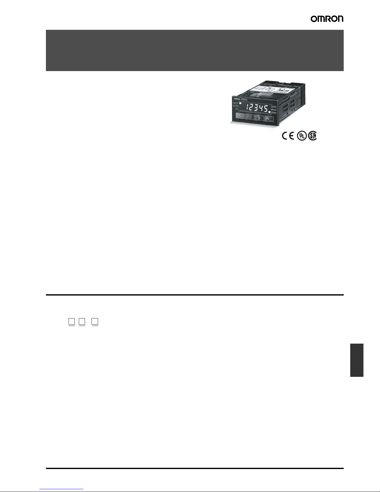
1/32 DIN Digital Panel Meter K3GN K-7
Panel
indicators
1/32 DIN Digital Panel Meter
K3GN
Compact and Intelligent Digital Panel Meter
• A single Panel Meter covering a wide range of applications.
3 main applicable functions:
• Process meter (DC voltage/current input).
• RPM processor/tachometer (frequency input).
• Digital data display for PC/PLC (RS-485 communications).
• Easy configuration
• Multi-range analog input: applicable for all standard analog
signals.
6 input ranges available: 4 to 20 mA/0 to 20 mA, 1 to 5 VDC/
0 to 5 VDC, ±5 VDC, ±10 VDC.
• 5 KHz max. input-pulse frequency range.
• Scaling in a wide range of engineering units.
• Programmable output operation action, decimal point
position setting, teaching function for input range, leading
zero suppression, average processing.
• Advanced and compact design
• Very compact 1/32 DIN housing: 48 (W) x 24 (H) x 83 (D).
• 5-digit display with programmable display color in red or
green.
• Good visibility: High contrast backlit LCD display.
• High protection against water and dust: NEMA4X/IP66 front
panel.
• Selectable outputs: 2 relay outputs, 3 transistor outputs,
RS-485, and combinations of these.
• High accuracy: ±0.1% full scale.
• Easy to configure through the front panel or via RS-485.
• EN/IEC conformity with CE marking and UL/CSA approval.
®
Model Number Structure
■ Model Number Legend
1. Input Type
ND: DC voltage/current, NPN
PD: DC voltage/current, PNP
2. Output Type
C: 2 relay contact outputs (SPST-NO)
T1: 3 transistor outputs (NPN open collector)
T2: 3 transistor outputs (PNP open collector)
3. Communications Output Type
None: Communications not supported
FLK: RS-485
24 VDC
12 3
K3GN - -
Page 2
K-8 1/32 DIN Digital Panel Meter K3GN
Ordering Information
■ List of Models
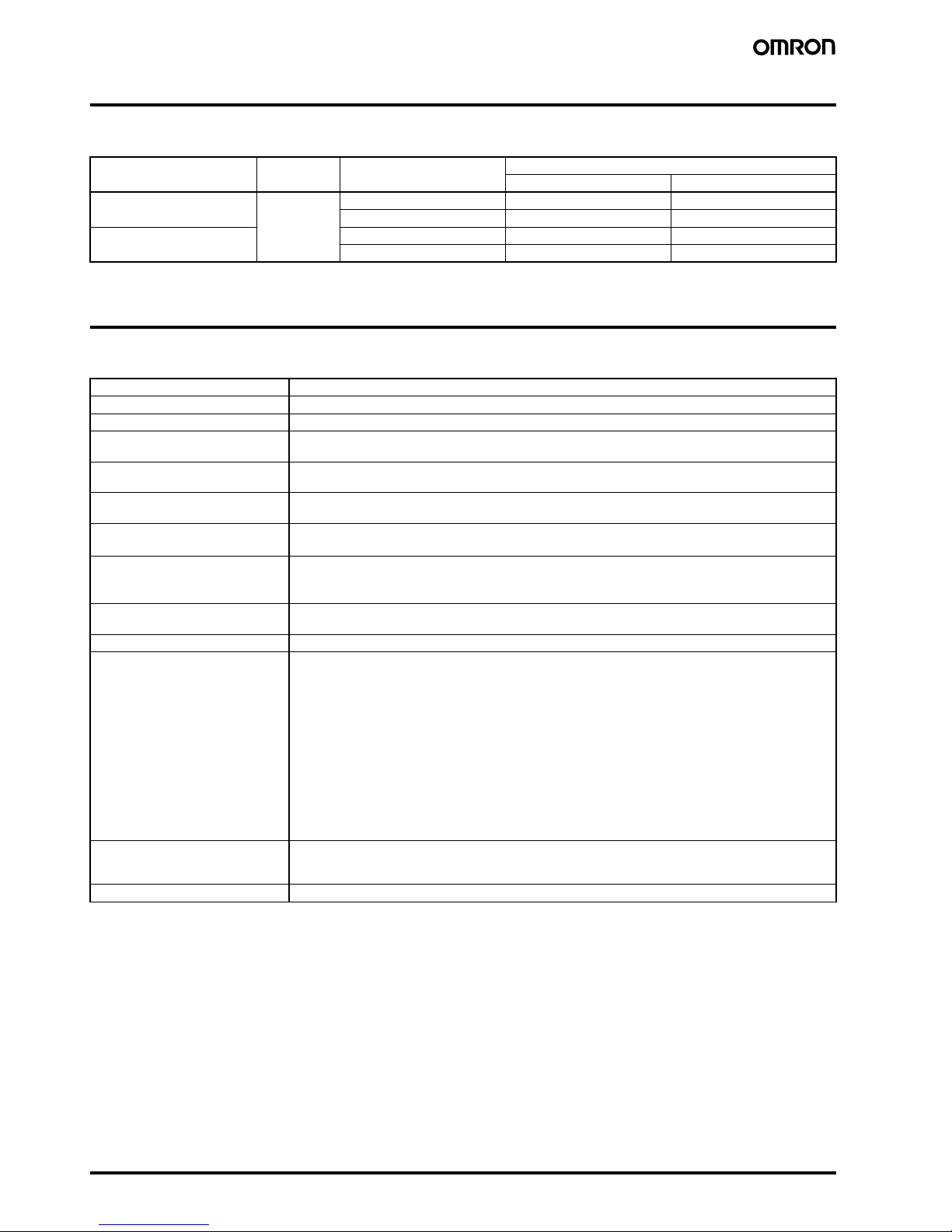
Specifications
■ Ratings
Note: A control power supply capacity greater than the rated capacity is required when the Digital Panel Meter is turned ON. Do not forget to take
this into consideration when using several Digital Panel Meters. When power is supplied, all indicators will light and outputs will be OFF.
When using startup compensation time operation, the display will read “00000” and all outputs will be OFF.
Input type Supply
voltage
Output Communications
No communications RS-485
DC voltage/current, NPN 24 VDC Dual relays (SPST-NO) K3GN-NDC 24 VDC K3GN-NDC-FLK 24 VDC
Three NPN open collector K3GN-NDT1 24 VDC K3GN-NDT1-FLK 24 VDC
DC voltage/current, PNP Dual relays (SPST-NO) K3GN-PDC 24 VDC K3GN-PDC-FLK 24 VDC
Three PNP open collector K3GN-PDT2 24 VDC K3GN-PDT2-FLK 24 VDC
Supply voltage 24 VDC
Operating voltage range 85% to 110% of the rated supply voltage
Power consumption (see note) 2.5 W max. (at max. DC load with all indicators lit)
Insulation resistance 20 MΩ min. (at 500 VDC) between external terminal and case.
Insulation provided between inputs, outputs, and power supply.
Dielectric strength 1,000 VAC for 1 min between external terminal and case.
Insulation provided between inputs, outputs, and power supply.
Noise immunity ±480 V on power supply terminals in normal mode, ±1,500 V in common mode, ±1 µs, or 100 ns for square-
wave noise with 1 ns
Vibration resistance
Malfunction: 10 to 55 Hz, 10 min each in X, Y, and Z directions; acceleration: 9.8 m/s
2
Destruction: 10 to 55 Hz, 30 min each in X, Y, and Z directions; acceleration: 19.6 m/s
2
Shock resistance
Malfunction: Models with transistor outputs: 196 m/s
2
for 3 times each in X, Y, and Z directions
Models with relay contact outputs: 98 m/s
2
for 3 times each in X, Y, and Z directions
Destruction: 294 m/s
2
for 3 times each in X, Y, and Z directions
Ambient temperature Operating: −10°C to 55°C (with no condensation or icing)
Storage: −25°C to 65°C (with no condensation or icing)
Ambient humidity Operating: 25% to 85% (with no condensation)
EMC (EMI) EN61326+A1 Industry
Emission Enclosure: CISPR 11 Group 1 class A: CISRP16-1/-2
Emission AC Mains: CISPR 11 Group 1 class A: CISRP16-1/-2
(EMS) EN61326+A1 Industry
Immunity ESD: EN61000-4-2: 4 kV contact discharge (level 2)
8 kV air discharge (level 3)
Immunity RF-interference: EN61000-4-3: 10 V/m (amplitude-modulated,
80 MHz to 1 GHz) (level 3)
Immunity Fast Transient Noise: EN61000-4-4: 2 kV (power line) (level 3)
Immunity Burst Noise: 1 kV line to line (I/O signal line)
Immunity Surge: EN61000-4-5: 1 kV line to line
2 kV line to ground (power line)
Immunity Conducted Disturbance EN61000-4-6: 3 V (0.15 to 80 MHz) (level 2)
Immunity Voltage Dip/Interrupting EN61000-4-11: 0.5 cycles, 0, 180°, 100% (rated voltage)
Approved standards UL508, CSA22.2;
Conforms to EN61326+A1, EN61010-1 (IEC61010-1)
Conforms to VDE0106/P100 (finger protection) when the terminal cover is mounted.
Weight Approx. 100 g
Page 3
1/32 DIN Digital Panel Meter K3GN K-9
Panel
indicators
■ Characteristics
Note 1. The minimum input time for control signals is 80 ms.
2. Refer to N102 Operation Manual for more details.
Input signal Process voltage
(1 to 5 V, 0 to 5 V, ±5V, ±10 V)
Process current
(4 to 20 mA, 0 to 20 mA)
No-voltage contact
(30 Hz max. with ON/OFF pulse width
of 16 ms min.)
Open collector
(5 kHz max. with ON/OFF pulse width
of 90 µs min.)
Digital data display (by RS-485
communication)
A/D conversion Double integral method
14 bit resolution
---
Sampling period 250 ms ---
Display refresh
period
Sampling period (sampling times multiplied by number of averaging times if average processing is selected.)
Pulse measurement
method
--- Periodic measurement ---
Connectable Sensors --- ON residual voltage: 2.5 V max.
OFF leakage current: 0.1 mA max.
Load current: Must have a switching capacity of 15 mA min.
Must be able to reliably switch load currents of 5 mA max.
Max. displayed digits 5 digits (−19999 to 99999)
Display 7-segment digital display, character height: 7.0 mm
Polarity display “−” is displayed automatically with a negative input signal.
Zero display Leading zeros are not displayed.
Scaling function Programmable with front-panel key inputs (range of display: −19999 to 99999). The decimal point position can be set as
desired.
External controls
(see note 1)
HOLD: (Measurement value held)
ZERO: (Forced-zero)
---
Hysteresis setting Programmable with front-panel key inputs (0001 to 9999).
Other functions Programmable Color Display
Selectable output operating action
Teaching set values
Average processing (simple average)
Lockout configuration
Communications writing control (communications output models only)
Forced-zero set with front panel keys
Control inputs (HOLD/ZERO) selection
via front panel keys
Field calibration
Startup compensation time (0.00 to 99.9 s)
Auto-zero time (0.0 to 19.9 s)
Output Relays: 2 SPST-NO
Transistors: 3 NPN open collector
3 PNP open collector
Combinations:
Communications output (RS-485) + relay outputs (2 SPST-NO);
Communications output (RS-485) + transistor outputs (3 NPN open collector);
Communications output (RS-485) + transistor outputs (3 PNP open collector)
Communications Communications function: RS-485
Delay in comparative
outputs
(transistor outputs)
750 ms max.
Degree of protection Front panel:NEMA4X for indoor use (equivalent to IP66)
Rear case: IEC standard IP20
Terminals: IEC standard IP20
Memory protection Non-volatile memory (EEPROM) (possible to rewrite 100,000 times)
Page 4

K-10 1/32 DIN Digital Panel Meter K3GN
■ Measuring Ranges
Process Voltage/Current Inputs
No-voltage Contact/Open Collector Inputs
Digital Data Display (By RS-485 Communications)
■ Input/Output Ratings
Relay Contact Output
(Incorporating G6K Relays)
Transistor Output
■ Communications Specifications
Refer to N102 Operation Manual for more details.
Input Measuring range Measuring accuracy Input impedance Displayable range
DC voltage 1.000 to 5.000 V/
0.000 to 5.000 V
±0.1% FS ±1 digit max.
(at 23±3°C)
1 MΩ min. −19999 to 99999
(with scaling function)
−5.000 to 5.000 V ±0.1% FS ±1 digit max.
(at 23±5°C)
−10.00 to 10.00 V
DC current 4.00 to 20.00 mA/
0.00 to 20.00 mA
±0.1% FS ±1 digit max.
(at 23±3°C)
60 Ω
Input Measuring range Measuring accuracy
(at 23±5°C)
Displayable range
No-voltage contact (30 Hz max.) with ON/
OFF pulse width of 16 ms min.
0.05 to 30.00 HZ ±0.1% FS ±1 digit max. −19999 to 99999
(with scaling function)
Open collector (5 kHz max.) with ON/OFF
pulse width of 90µs min.
0 to 5000 HZ
Displayable range −19999 to 99999
Item Resistive load (cosφ = 1)
Rated load 1 A at 30 VDC
Rated carry current 1 A max. (at COM terminal)
Max. contact voltage 60 VDC
Max. contact current 1 A (at COM terminal)
Max. switching capacity 30 VA
Min. permissible load
(P level, reference value)
10 mV, 10 µA
Mechanical life 50,000,000 times min. (at a switching frequency of 36,000 times/hr)
Electrical life
(at an ambient temperature of 23°C)
100,000 times min. (at the rated load with a switching frequency of 1,800 times/hr)
Rated load voltage 24 VDC
Max. load current 50 mA
Leakage current 100 µA max.
Item RS-485
Transmission method 2-wire, half-duplex
Synchronization method Start-stop synchronization
Baud rate 1,200/2,400/4,800/9,600/19,200 bps
Transmission code ASCII
Communications Reading/Writing to
the K3GN
Read/write set values, read/write scaling values, enable/disable the writing of data through communications, forced-zero control, and other data.
Page 5
1/32 DIN Digital Panel Meter K3GN K-11
Panel
indicators
Connections
■ Terminal Arrangement
Note: *Operation power supply 24VDC: Recommended DC power supply: eg. OMRON s8VS
Terminal No. Name Description
A-B Operation power Connect the operation power supply.
C-B Event input or pulse/contact input Operates as follows depending on parameter
setting:
• Holds process value.
• Calibrate the process value to zero and clear
the forced-zero function.
• Pulse or contact input.
C-A
D,F-E Analog input Connect the voltage or current analog input.
G-H Communications RS-485 communications terminals.
I,K-L Outputs Outputs relay or transistor outputs. There is
also a PASS output for models with transistor
outputs.
I,J,K-L
B (+) A (−)
78
7
8
C
12
3
1
2
3
A
9101112
9101112
9101112
D
456
B
C
D
AB
78 9101112
123 456
Output terminals
Input terminals
NC NC
RS-485
Models with NPN inputsModels with PNP inputs
OUT1
PASSNCOUT2
COM
OUT1
OUT2
COM
OUT1 PASS OUT2 COM
Voltage Current
Analog input
COM
Event or pulse/contact input
Event or pulse/contact input
Analog input
Models without
communications
Models with
communications
Operation
power supply
24 VDC*
Operation
power supply
24 VDC*
Models with
PNP transistor outputs
Models with
NPN transistor outputs
Models with
relay outputs
Page 6
K-12 1/32 DIN Digital Panel Meter K3GN
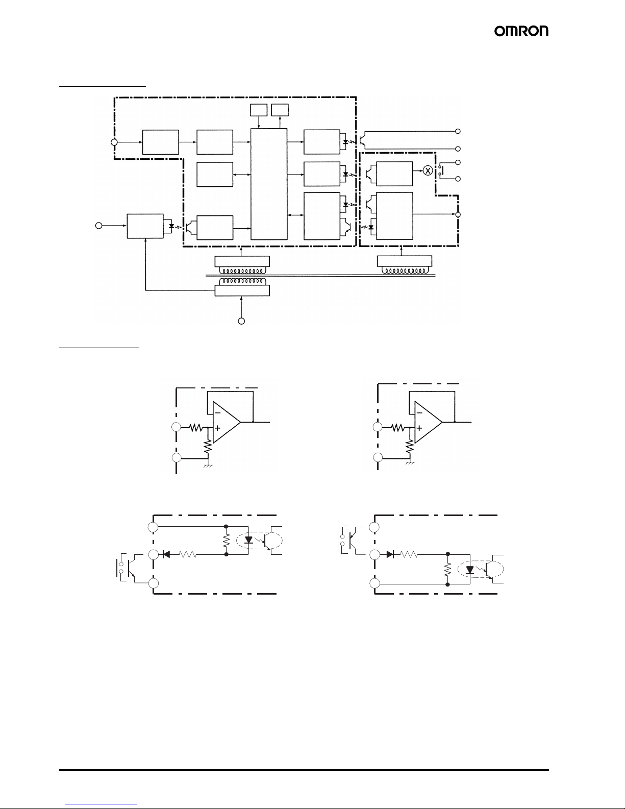
■ Wiring
Block Diagram
Input Circuits
Analog Input (DC Voltage/Current)
Pulse Input/Control Event Input (HOLD/ZERO)
DisplayKey
Drive circuit
Drive circuit
Drive circuit
Constant voltage circuit 1
Power supply circuit
Input circuit
Operating power supply
Constant voltage circuit 2
EEPROM
Analog input
terminal
Pulse/
Control
input
terminal
Control input
circuit
A/D
conversion
circuit
Wavefo rm
rectification
circuit
Microcomputer
Note: 1. Transistor output models only.
2. Relay output models only.
3. Models with communications functions only.
Output
circuit
Communications driver
Transistor output
(See note 1.)
Contact output
(See note 2.)
Communications terminal
(See note 3.)
5
4
5
6
A
60 Ω
A+B=1 MΩ
B
Voltage input
COM
Current input
COM
To A / DTo A/D
2
3
24 VDC +
4.7 k
Ω
2.35 k
Ω
3
4.7 k
Ω
2.35 k
Ω
2
24 VDC
−
24 VDC +
24 VDC
−
1
1
PNP Input
NPN Input
Hold/Zero Pulse
Hold/Zero Pulse
Page 7
1/32 DIN Digital Panel Meter K3GN K-13
Panel
indicators
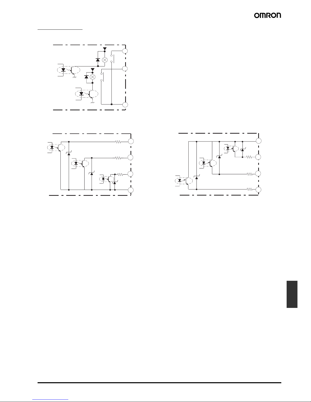
Output Circuits
Contact Output
Transistor Output
9
11
12
5 V
5 V
OUT1
OUT2
OUT3
9
10
11
12
8.2
Ω
8.2
Ω
8.2
Ω
OUT1
OUT2
PA SS
COM
NPN Output
9
10
11
12
8.2
Ω
8.2
Ω
8.2
Ω
OUT1
OUT2
PA SS
COM
PNP Output
Page 8

K-14 1/32 DIN Digital Panel Meter K3GN
Operation
■ Main Functions
Input Types and Ranges
Scaling
Analog (Process) Inputs
The K3GN converts input signals into desired physical values.
INPUT2: Any input value
DISPLAY2: Displayed value corresponding to INPUT2
INPUT1: Any input value
DISPLAY1: Displayed value corresponding to INPUT1
Pulse Frequency
The K3GN converts pulse signal inputs into desired units such as
revolutions or rotational speeds.
The slope of the linear relationship between the input value and display value is calculated automatically when an input value and its
corresponding display value are entered.
Input value: Any arbitrary input value
Display value: Desired display value corresponding to input value
If scaling for pulse signals is not performed, the input frequency will
be displayed.
The relationship between input, f, and display, D, is expressed in the
form D = f × a (multiplication factor). The value of a will vary accord-
ing to the display unit. For example, if the display unit is rpm, Y is
given by the following:
D = f × 1/N × 60 (i.e., a = 1/N × 60)
where N is the number of pulses per revolution and f is the input
pulse frequency (Hz).
If the display unit is m/min, Y is given by the following:
D = f × πd × 1/N × 60 (i.e., a = πd × 1/N × 60)
where πd = the wavelength (m) per revolution.
Example: When displaying the rotational speed (rpm) for a machine
that generates 5 pulse signals per revolution, D is given by the following:
D = f × 1/5 × 60,
so if f = 1, then D = 12. Therefore, input 1 for inp and 12 for dsp.
Average Processing
The average processing function stabilizes displayed values by averaging the corresponding input signals that fluctuate dynamically.
Hysteresis
The hysteresis of comparative outputs can be set to prevent the chattering of relay or transistor outputs.
Input type (setting parameter) Function Input range (setting parameters) Setting range
Analog input (analg) Selects DC voltage/current signal
input.
4 to 20 mA/0 to 20 mA (4-20) Displayable from −19999 to 99999
with scaling function. The position
of the decimal point can be set as
desired.
1 to 5 V/0 to 5 V (1-5)
±5 V (5)
±10 V (10)
Pulse input (pulse) Selects pulse input signal. 0.05 to 30 Hz (30)
0 to 5 kHz (sk)
Remote (rmt) Displays digital data from PLC or
PC.
---
Input value
INPUT1 INPUT2
Input value
Displayed value
Displayed value
DISPLAY1 DISPLAY2
DISPLAY1 DISPLAY2
INPUT2 INPUT1
inp
dsp
Input value
Displayed value
K3GN
Proximity Sensor
Upper limit (high acting)
Set value
Output
ON
OFF
Hysteresis
Measurement value
Page 9

1/32 DIN Digital Panel Meter K3GN K-15
Panel
indicators
Startup Compensation Time (Pulse
Input Only)
The startup compensation time parameter keeps the measurement
operation from sending an unnecessary output corresponding to
instantaneous, fluctuating input from the moment the K3GN is turned
ON until the end of the preset period.
The compensation time can be set in a range from 0.0 to 99.9 seconds as the waiting time until the devices subject to measurement
become stable after the startup of the power supply.
Changing the Display Color
The display can be programmed to change color when an output
turns ON. In an example, the K3GN can be programmed to display
Green for normal, and Red for errors. The color can be set to change
from either green to red or red to green when output turns ON.
K3GN can also be programmed to display only one unchanging
color: Red or Green.
Teaching
An actual measured value as a set value without any front panel key
input can be set with the teaching function. Teaching is useful for
making settings while checking the operation status of K3GN.
Forced-zero Function
It is possible to shift the zero point to a desired value (such as might
be required when adjusting reference values) with one touch of the
Up/Zero Key on the front panel.
Configurable Output Operating Action
Output 1 and output 2 can be set to operate in one of the 3 following modes:
• Upper limit (High Acting):
The output is turned ON when the measured value is greater than its set value.
• Lower limit (Low Acting):
The output is turned ON when the measured value is less than its set value.
• Upper and lower limits (Outside band Acting):
An upper limit (H set value) and lower limit (L set value) can be set independently.
The output is turned ON when the measured value is greater than upper-limit set value or less than the lower-limit set value.
Only transistor outputs have a PASS output which is output when both OUT1 and OUT2 are OFF.
The three types of output operations shown above can be combined as desired. The following are examples of possible combinations.
OUT1
OUT2
SV
ZERO
HOLD
CMW
Upper Limit (High Acting)
OUT1/2 set value
Measurement value
ON
OFF
Output
Hysteresis
Lower Limit (Low Acting)
OUT1/2 set value
ON
OFF
Output
Hysteresis Hysteresis
Measurement value
Hysteresis
ON
OFF
Output
Measurement value
Upper and Lower Limits
(Outside Band Acting)
Upper-limit set value
for OUT1/2
Lower-limit set value
for OUT1/2
Upper Limit 2-stage Output Threshold Output
ON
OFF
OUT2
ON
OFF
OUT1
OUT1 set value
ON
OFF
OUT2
ON
OFF
OUT1
ON
OFF
OUT2
ON
OFF
OUT1
OUT2
set value
OUT1
set value
Measurement
value
Upper-limit OUT2
set value
Upper-limit OUT1
set value
Lower-limit OUT1
set value
Lower-limit OUT2
set value
Measurement
value
Combination of Upper Limit and
Upper/Lower Limits
Upper-limit
OUT2 set value
Lower-limit
OUT2 set value
Measurement
value
Page 10

K-16 1/32 DIN Digital Panel Meter K3GN
Nomenclature
Name Functions
1. Main display Displays process values, parameters, and set values.
2. Status indicators OUT1 Lit when output 1 is ON.
OUT2 Lit when output 2 is ON.
SV Lit when a set value is being displayed or changed.
T Lit when the teaching function is enabled. Flashes when the K3GN is in teaching operation.
Lit when a calibration value is being displayed during user calibration. Flashes while reading a calibration value.
ZERO Lit while the forced-zero function is activated.
HOLD Lit when HOLD input is ON.
CMW Lit when communications writing is “enabled” and is out when it is “disabled.”
3. Level indicator Displays the current level that the K3GN is in. (See below for details.)
4. Level Key Used to change the level.
5. Mode Key Used to allow the Main display to indicate parameters sequentially.
6. Shift Key Used to enable that set value to be changed. When changing a set value, this key is used to move
along the digits.
7. Up/Zero Key Used to change a set value. Used to set or clear a forced-zero function when a measurement value is
being displayed.
1. Main display
2. Status indicators
3. Level indicator
4. Level key
2. Status indicators
7. Up/Zero key6. Shift key5. Mode key
Level indicator Level
p
Protect
Not lit Operation
a
Adjustment
s
Initial setting
c
Communications setting
f
Advanced function setting
u
User calibration
Page 11

1/32 DIN Digital Panel Meter K3GN K-17
Panel
indicators
Dimensions
Note: All units are in millimeters unless otherwise indicated.
Application Examples
Detection of Dust Exhaust
The change in the density of the dust is detected via the E3SA and
discriminated by the K3GN.
Monitoring of Tank Pressure
The output of the pressure sensor is processed and the pressure is
displayed. Remote monitoring of the operation is possible with the
communications function.
22.2
+0.3
0
22.2
+0.3
0
45
+0.6
0
3.6 mm
7 mm
Main Display Character Size
Panel Cutouts
Gang Mounting
(48 × No. of Panels − 2.5)
+1.0
0
40 min.
Separate
mounting
The products cannot be
made waterproof when
gang-mounted.
The K3GN uses M3 terminals. A terminal
cover is provided.
Exhaust
Grinder Dust collecting machine
E3SA
4 to 20 mA
K3GN
OUT2
(Upper upper-
limit alarm)
Device stops
OUT1
(Upper-limit
alarm) Output
reduction
instruction
Foam
Beer
Tank
Exhaust valve
Pump
K3GN
Host PC
RS-485
RS-232C
E8AA
Pressure
Sensor
Page 12

K-18 1/32 DIN Digital Panel Meter K3GN
Monitoring of Motor Load Current
If the startup time compensation of the K3GN is enabled, the K3GN
will not be influenced by the inrush current from starting the motor,
and no signal will be output from the K3GN.
Note: *Power Supply: Recommended DC power supply:
eg. OMRON S8VS.
Monitoring Difference between Two
Line Speeds
The difference between the two line speeds is calculated by the PLC
and the result is written via RS-485 to the K3GN where it is displayed.
Position Indication on X-Y Table
The position on the X-Y table is calculated by the PLC and the result
is written via RS-485 to the K3GN where it is displayed. The scaling
function can be used to display the result in millimeter units.
Monitoring the Remaining Quantity of
Soup
The distance to the surface of the soup is detected with an ultrasonic
sensor and, based on this distance, the K3GN displays the remaining
quantity. When the remaining quantity of soup decreases to less than
20%, the K3GN lights the “Replenish” indicator.
Monitoring Number of Motor
Revolutions
Note: *Power Supply: Recommended DC power supply:
eg. OMRON S8VS.
Power supply*
Signal input
K3GN
24-VDC power supply*
Electromagnetic relay
K3FK
CT Converter
OUT1
(Upper-limit
alarm)
OUT2
(Lower-limit
alarm)
RS-485 communications output
(calculation result)
K3GN
(Set the input type to
"Remote").
X
Y
PLC
mm
mm
00
135.4
PLC
X-Y Table
RS-485 Communication output
K3GN
(Set the input type to
"Remote".)
100 %
20 %
4 to 20 mA
K3GN
Volume of soup
OUT 1
Replenish
E4PA-LS50-M1
Ultrasonic Sensor
Large
cup
Medium
cup
Small
cup
Power supply*
Signal input
24-VDC power supply*
Electromagnetic relay
0 to 1 A
4 to 20 mA
K3FK CT Converter
K3GN-NDC
K3GN-NDC
OUT1 (Upper limit)
OUT1 (Upper limit)
OUT2 (Lower limit)
OUT2 (Lower limit)
E2E Proximity
Sensor
Page 13

1/32 DIN Digital Panel Meter K3GN K-19
Panel
indicators
Precautions
!WARNING
Do not touch any of the terminals while power is being supplied.
Doing so may result in electric shock. Also, do not touch the terminals with a screwdriver while power is being supplied. Electrical
shock may result via the screwdriver.
!Caution
Do not allow metal objects or conductive wire cuttings to enter the
product. Doing so may result in electric shock, fire, or malfunction.
!Caution
Do not attempt to disassemble, repair, or alter the product. Doing
so may result in electric shock, fire, or malfunction.
!Caution
Do not use the product where flammable or combustion gasses
are present.
!Caution
The lifetime of output relays varies greatly with the switching capacity and conditions. Consider the actual operating conditions,
and use the product within the rated load and electrical service life.
!Caution
Do not use loads exceeding the rated value. Doing so may result
in damage or burning.
!Caution
Use a power supply voltage within the specified ratings. Not doing
so may result in damage or burning.
!Caution
Be sure to tighten the terminal screws securely. The recommended tightening torque is 0.5 N·m. Loose screws may result in product failure or malfunction.
!Caution
Perform correct setting of the product according to the application.
Failure to do so may cause unexpected operation, resulting in
damage to the unit or injury.
!Caution
This product is not a safety device. Product failure may prevent operation of comparative outputs. Take safety measures, such as installing a separate monitoring system, to ensure safety and to
prevent serious accidents caused by such failure, thus ensuring
safety.
Observe the following precautions to ensure safety:
1. Do not connect anything to unused terminals.
2. Be sure to check each terminal for correct number and polarity
before connection. Incorrect or reverse connection may damage
or burn out internal components of the K3GN.
3. Do not use the product in locations subject to the following:
• Dust or explosive gasses (e.g., sulfide gas or ammonia gas).
• Condensation or icing as a result of high humidity.
• Outdoors or in direct sunlight.
• Splashing liquid or oil atmosphere.
• Direct radiant heat from heating equipment.
• Extreme changes in temperature.
4. Do not block heat dissipation around the product, i.e., provide suf-
ficient space for heat dissipation. Do not block the ventilation
holes on the back of the product.
5. Do not use paint thinner for cleaning. Use commercially available
alcohol.
6. Use a power supply meeting the power supply specifications of
the K3GN. Be sure that the rated voltage is achieved within 2 s
after turning ON the power.
7. Use the K3GN within the specified temperature and humidity
ranges. When installing the K3GN in a panel, be sure that the
temperature around the K3GN (not the temperature around the
panel) does not exceed 55°C. If the K3GN is subject to radiant
heat, be sure that the temperature of the surface of the K3GN
exposed to the radiant heat does not exceed 55°C by providing a
fan or other heat removal method.
8. Store the K3GN within the specified temperature and humidity
ranges.
9. Do not lay heavy objects on the product during use or storage.
Doing so may deform or deteriorate the K3GN.
10.Conduct aging for 15 minutes min. after power is ON for correct
measurement.
Mounting
Recommended panel thickness is 1 to 5 mm.
Insert the K3GN in the square cutout, insert the adapter from the
back, and push the K3GN into the cutout as far as possible. Use
screws to secure the K3GN. To make the K3GN waterproof, insert
watertight packing in the K3GN.
Install the watertight packing in the proper direction. Note that the
packing is direction-sensitive.
When gang-mounting two or more products in a cutout, be sure that
the ambient temperature does not exceed the specifications.
Mount the K3GN as horizontally as possible.
Separate the K3GN from machines generating high-frequency noise,
such as high-frequency welding machines and high-frequency sewing machines.
Operation
A K3GN model with a relay contact or transistor output may not output any alarm signal normally if the model has an error. It is recommended that an independent alarm device be connected to the
model.
The parameters are factory-set so that the K3GN will operate normally. The settings of the parameters may be changed according to
the application.
Wiring
Wire the power supply with the correct polarity. Wiring with incorrect
polarity may result in damage or burning.
Wire the terminals using crimp terminals.
Tighten terminal screws to a torque of approx. 0.5 N·m.
Wire signal lines and power lines separately to reduce the influence
of noise.
Use M3 crimp terminals of the type shown below.
5.8 mm max.
5.8 mm max.
Page 14

K-20 1/32 DIN Digital Panel Meter K3GN
Operating Procedures
■ Initial Settings
Specify set value of OUT 1 and 2.
Measurement starts.
Power ON
Press the Level Key @ for 3 s min. to move to the initial setting
level.
Select the input type and specify the analog input range or
pulse frequency input range.
Set the scaling values and specify output operating action as
required.
With communications output models, press the Level Key @ for
less than 1 s to move to the communications setting level.
After making communications settings, press the Level Key @
for less than 1 s to move to the initial setting level.
Move to the advanced function setting level and make settings
for average processing, HOLD/ZERO selection, hysteresis values, auto-zero time, startup compensation time, display color
programming, and other advanced function parameters as required.
Press the Level Key @ for less than 1 s min. to return to the
operation level.
Page 15

1/32 DIN Digital Panel Meter K3GN K-21
Panel
indicators
■ Levels
“Level” refers to a grouping of parameters. The following table lists the operations that are possible in each of the levels, and how to move between
levels. There are some parameters that are not displayed for certain models.
Note: The move to protection level time can be set in the advanced function setting level.
Level name Function Measurement
Protect Setting lockouts. Continue
Operation Displaying process values, setting/clearing forced-zero function, and
setting OUT 1/2 set values.
Continue
Adjustment Setting communications writing control. Continue
Initial setting Making initial settings of input type, scaling, output operating action,
and other parameters.
Stopped
Communications setting Setting baud rate, word length, and other communications data. Stopped
Advanced function setting Setting average processing, display color settings, and other ad-
vanced function parameters.
Stopped
Calibration Setting user calibration of the inputs. Stopped
+
+
-1234.5
Protection
Operation
Adjustment
Power ON
1 s min.
1 s min.
Initial setting
Password "−0169"
1 s min.
Calibration
Password "1201"
Continue to press the key for 2 s min.
Indicates change of level.
1 s min.
Less than 1 s
Less than 1 s
(see note)
Time set
by user
Flashing stops if key
is released.
Communications
setting
Advanced function
setting
Page 16

K-22 1/32 DIN Digital Panel Meter K3GN
■ Parameters
−
−
−
−
−
−
−
Adjustment level
Press Level Key for less than 1 s.
Power ON
Operation level
Set one
of these.
Set one
of these.
Process value
Note: 1. Some parameters are not displayed for certain models.
2. The K3GN will stop measurement if the level is changed to the initial setting level, the
advanced function setting level, the communications setting level, or the calibration
level.
3. If the input range is changed, some parameters are set to default values. Therefore,
set the input range first.
4. Settings displayed in reverse black/white are defaults.
Communications
writing
control
OUT1
set value
Upper-limit
OUT1 set
value
Lower-limit
OUT1 set
value
OUT2
set value
Upper-limit
OUT2 set
value
Lower-limit
OUT2 set
value
Monitor Status
Setting Status
Next parameter
The set value
flashes.
If there is no key operation for 5 seconds,
the setting is registered and the display
returns to monitor status.
Change the set
value using the
Up Key and
the Shift Key .
Changing Set Values
While parameters are being displayed, set values can be displayed
by pressing the Shift Key (monitor status).
Pressing the Shift Key again will make it possible for this set value
to be changed (setting status). The part that can be changed will
flash.
Change the set value as required, and press the Mode Key to register the setting and move to the next parameter.
Page 17

1/32 DIN Digital Panel Meter K3GN K-23
Panel
indicators
−
−
−
−
−
−
−
−
−
Press Level Key for less than 1 s.
For analog input
For pulse input
For pulse input
Press Level Key for more than 1 s.
Enter password "−0169"
Unit: times
Unit: s
Unit: s
Unit: s
Unit: ms
For pulse input
Input type
Analog
Pulse
Baud rate
Stop bits
Parity bits
None
Even
Odd
Initial setting level
Green (red)
Green
Red (green)
Red
Unit: Hz
Upper Limit
Lower Limit
Upper Limit
Lower Limit
Unit: s
For analog input
Enter password "1201"
Calibration level
Communications
setting level
Communications
unit no.
Word
length
Press Level Key
for more than 3 s.
Press Level
Key for
more than 1 s.
Remote
(digital
data display)
Analog
input
range
Input-pulse
frequency
range
For analog/
remote input
Input
value 1
for
scaling
Display
value 1
for
scaling
Input
value 2
for
scaling
Display
value 2 for
scaling
Input
value for
scaling
Display
value for
scaling
Decimal
point
position
Operating
Action for
OUT1 set
value
Operating
Action for
OUT2 set
value
Move to
advanced
function
setting level
Upper/Lower
Limits
Upper/Lower
Limits
Move to
calibration
level
Send
waiting
time
Move-toprotectlevel time
Display
Auto-return
time
Display
color
change
Startup
compensation
time
Auto-zero
time
OUT2
Hysteresis
OUT1
Hysteresis
For analog/
remote input
HOLD/
ZERO
selection
Average
processing
Parameter
initialization
Advanced function
setting level
−
−
−
−
−
−
−
−
−
− −
−
−
− −
Page 18

K-24 1/32 DIN Digital Panel Meter K3GN
Operation/Adjustment Lockouts
Prohibits key operations for operation level and adjustment level.
• Initial setting is 0.
• When the set value is 0 (the initial setting), protection is not set.
Setting Change Lockout
Prohibits setting changes.
• The initial setting is OFF.
Note: Changes to protection level parameters, moving to advanced
function setting level, and moving to calibration level are all allowed.
Initial Setting/Communications
Lockouts
Prohibits moving to the initial setting level, the communications setting level, and the advanced function setting level.
• The initial setting is 1.
Forced-zero shift Lockout
Prohibits the setting or clearing of a forced-zero using the front panel
key.
• The initial setting is OFF.
p
p
p
p
Protect level
Setting change lockout
• Prohibits setting changes using front panel keys.
Operation/adjustment
lockouts
Initial setting/communications lockouts
Forced-zero shift
lockout
• Prohibits menu display, writing, etc., for
operation level and adjustment level.
• Prohibits access to menu display, initial setting
level, communications setting level, and
advanced function setting level.
• Prohibits use of the forced-zero function using
front panel keys.
Setting Operation level Moving to
adjustment
level
Process value
display
Set value display
0 Allowed Allowed Allowed
1 Allowed Allowed Prohibited
2 Allowed Prohibited Prohibited
Setting Meaning
OFF Setting changes using front panel keys allowed (i.e., it is
possible to move to the state where changes to settings
can be made).
ON Setting changes using front panel keys prohibited (i.e., it
is not possible to move to the state where changes to
settings can be made).
Setting Moving to initial setting
level
Moving to
communications setting
level
0 Allowed (message for mov-
ing to advanced function
setting level displayed)
Allowed
1 Allowed (message for mov-
ing to advanced function
setting level not displayed)
Allowed
2 Prohibited Prohibited
Setting Meaning
OFF Executing and clearing of forced-zero allowed.
ON Executing and clearing of forced-zero prohibited.
Page 19

1/32 DIN Digital Panel Meter K3GN K-25
Panel
indicators
■ Troubleshooting
When an error occurs, error details will be displayed on the main display. Confirm the error from the main display and take the appropriate countermeasures.
Main display Level
display
Error contents Countermeasure
e111 (E111) Not lit RAM memory error Turn the power supply OFF and ON again. If the same error is displayed
even after the power is turned OFF and ON, it is necessary to replace
the memory. If normal operation is restored by turning the power supply
OFF and ON, it is possible that there is noise interference. Check that
there is nothing in the vicinity that may be the source of noise.
e111 (E111) 5 EEPROM memory
error
s.err (S.Err)
(Flashes at 0.5-s intervals)
Not lit Input error or input
range exceeded
All outputs turn OFF.
Check for incorrect input wiring, for disconnected power lines, for short-
circuiting, and the input type.
Bring the input value within range.
99999
(Flashes at 0.5-s intervals)
Not lit Greater than
displayable range
This is not an operational error. These messages are displayed when a
value to be displayed lies outside the displayable range, even if the input
value is within the input range and the range for which measurement is
possible.
Bring the input value and display value within range.
-19999
(Flashes at 0.5-s intervals)
Not lit Less than displayable
range
Page 20

K-26 1/32 DIN Digital Panel Meter K3GN
Additional Information
■ Application as a Process Meter
The initial settings required when using the K3GN a process meter are explained below using the following example.
Setting Example
Inputs in the range 1 to 5 V are scaled to the range 0 to 100.0 kg and
displayed. If the measurement value goes over 70.0 kg, output 1
turns ON. If the measurement value goes below 50.0 kg, output 2
turns ON.
Initial Setting Procedure
1. Check the wiring and turn ON the power.
2. Set analog input as the input type.
If a measurement value is displayed (operation level), move to the
initial setting level by holding down the Level Key for 3 s min.
Set parameter in-t to analg.
3. Set the analog range to 1 to 5 V.
Set parameter range to 1-5.
4. Set the scaling values.
Set parameter inp.1 to 1.000.
Set parameter dsp.1 to 0.
Set parameter inp.2 to 5.000.
Set parameter dsp.2 to 1000.
5. Set the position of the decimal point.
Set parameter dp to %%%%.%.
6. Operating action for OUT1 and OUT2 set values.
Set parameter out1.t to hi.
Set parameter out2.t to lo.
7. Set OUT1 set value to 70.0 and OUT2 set value to 50.0.
If an initial setting level parameter is displayed, press the Level
Key for 1 s min. to return to the operation level.
Set parameter out1 to 70.0.
Set parameter out2 to 50.0.
8.
Start actual operation.
■ Application as a Tachometer
The initial settings required when using the K3GN as a tachometer are explained below using the following example.
Setting Example
The speed of a conveyor belt is displayed in m/min units. For every
revolution of the shaft, 4 pulses are output. The diameter of the axis
of rotation is 12 cm. If the Rotational speed goes over 10.500 m/min,
output 1 turns ON. If the speed goes below 9.500 m/min, output 2
turns ON.
Deciding the Scaling Value
Rotational speed (m/min) = π × Diameter (m) × Revolutions per
minute (rpm)
Revolutions per minute (rpm) = Input frequency (Hz) ÷ Number of
pulses per revolution × 60
Applying the appropriate values to these 2 equations gives: Speed
(m/min) = 5.654866... × Input frequency (Hz)
Multiply by 1,000 to display the first 3 digits to the right of the decimal
point.
Speed (m/min) = 5654.866... × Input frequency (Hz)
100.0 kg
0.0 kg
1.000 V
5.000 V
50.0 kg
70.0 kg
Input value
Output 2 Output 1
Normal
Displayed
value
12 cm
Output
1
9.500
m/min
10.500
m/min
Normal
Output
2
56549
10 Hz Input value
Displayed
value
To limit inaccuracies due to scaling, select a round number
(e.g., 10) as the input value and select a display value of as
many digits as possible. In this example, scaling is performed
so that an input value of 10 gives a displayed value of 56549.
Page 21

1/32 DIN Digital Panel Meter K3GN K-27
Panel
indicators
Initial Setting Procedure
1. Check the wiring and turn ON the power.
2. Set pulse input as the input type.
If a measurement value is displayed (operation level), move to the
initial setting level by holding down the Level Key for 3 s min.
Set parameter in-t to pulse.
3. Set the pulse frequency to 30 Hz.
The input pulse frequency for the application is approximately
2 Hz and so can be assumed not to exceed 30 Hz. Set parameter
p-fre to 30.
4. Set the scaling values.
Set parameter inp to 10.
Set parameter dsp to 56549.
5. Set the decimal point.
Set parameter dp to %%.%%%.
6. Operating action for OUT1 and OUT2 set values.
Set parameter out1.t to hi.
Set parameter out2.t to lo.
7. Set OUT1 set value to 10.500 and OUT2 set value to 9.500.
If an initial setting level parameter is displayed, press the Level
Key for 1 s min. to return to the operation level.
Set parameter out1 to 10.500.
Set parameter out2 to 9.500.
8.
Start actual operation.
Page 22

K-28 1/32 DIN Digital Panel Meter K3GN
In the interest of product improvement, specifications are subject to change without notice.
ALL DIMENSIONS SHOWN ARE IN MILLIMETERS.
To convert millimeters into inches, multiply by 0.03937. To convert grams into ounces, multiply by 0.03527.
Cat. No. N101-E1-03
 Loading...