

Page 1

USER’S MANUAL
1/32 DIN Digital Panel Meter
K3GN
Cat. No. N102-E1-04
Page 2

PREFACE
This User’s Manual provides you with information necessary
for use of the K3GN series of digital panel meters.
Please read this manual carefully to ensure correct and efficient use of the product.
Keep this manual handy for future reference.
General Precautions
If contemplating using the product in the following environments or for the following equipment,
first contact a sales representative of the company and then accept responsibility for incorporating
into the design fail-safe operation, redundancy, and other appropriate measures for ensuring
reliability and safety of the equipment and the overall system.
(1) Environments deviating from those specified in this manual
(2) Nuclear power control systems, traffic (rail car/automobile/aircraft) control systems, medical
equipment, amusement equipment, and rescue and security equipment
(3) Other equipment that demands high reliability, including those related to the safety of life and
property
About the Contents of the Manual
(1) Any reproduction, full or in part, of the manual is prohibited without prior written
permission from the company.
(2) Specifications in the manual may be subject to change without notice.
(3) Information in the manual has been carefully checked for accuracy. If finding any
suspicious or erroneous descriptions in the manual, however, you are kindly requested
to contact a branch office of the company. In such a case, please let us know the Cat.
No. shown on the front cover of the manual.
I
Page 3

Other Informations
1 Warranty
(1) Warranty Period
The warranty period for an OMRON Product is one year from either the date of purchase or the date on which the
OMRON Product is delivered to the specified location.
(2) Extent of Warranty
If an OMRON Product is subject to a failure for which OMRON is responsible during the warranty period, either a
replacement product will be provided or the defective product will be repaired free of charge at the place of
purchase, This warranty, however, will not cover problems that occur as a result of any of the following.
a) Using the OMRON Product under conditions or in an environment not described in catalogs or in the
specifications, or not operating the OMRON Product according to the instructions contained in catalogs or
in the specifications.
b) Problems caused by something other than the OMRON Product.
c) Modifications or repairs performed by a party other than OMRON.
d) Using the OMRON Product for other than its designed purpose.
e) Problems that could not have been foreseen with the level of science and technology that existed at the time
the OMRON Product was shipped.
f) Problems caused by an Act of God or other circumstances for which OMRON is not responsible.
This warranty covers only the OMRON Product itself. It does not cover any other damages that may occur
(1) OMRON shall not be responsible for special, indirect, or consequential damages originating in an OMRON
(2) For programmable OMRON Products, OMRON does not accept responsibility for any programming that is
(1) When using OMRON Products in combination with other products, it is use’s responsibility to confirm
(2) When using OMRON Products in any of the following applications, consult an OMRON representative and check
(3) When OMRON Products are used in an application that could pose significant risk to human life or property, the
(4) Application examples provided in catalogs are for reference only. Confirm functionality and safety before actually
(5) To prevent unexpected problems from arising due to the OMRON Product being used incorrectly by the customer
directly as a result of a problem with the OMRON Product.
2 Limitations of Liability
Product.
performed by a party than OMRON, or for any results arising from that programming.
3 Applicable Conditions
the suitability of the OMRON Products for the system, devices, and equipment that are being used. OMRON
accepts no responsibility for the suitability of OMRON Products used in combination with other products.
specifications to allow sufficient leeway in ratings and performance, and to implement suitable safety measures,
such as safety circuits, to minimize danger in the event of an accident.
a) Outdoor applications, applications with potential for chemical contamination or electrical interference, or
application under conditions or environments not described in catalogs.
b) Nuclear control systems, railroad systems, aviation systems, vehicles, combustion systems, medical equipment,
amusement machines, or equipment regulated by government or Industrial standards.
c) Other systems, machines, and equipment that may have a serious influence on human life and property.
d) Equipment requiring a high level of reliability, such as gas, water, or electrical supply systems, and systems that
operate 24 hours a day.
e) Other applications requiring a high level of safety, corresponding to points a) to d), above.
overall system must be designed so that the required safety can be ensured by providing notice of the danger and
incorporating redundancy into the design. Make sure that OMRON Products are appropriately wired and mounted to
serve their intended purpose in the overall system.
using the devices and equipment.
or any other party, make sure that you understand and carefully observe all of the relevant prohibitions and
precautions.
4 Changes to Specifications
Specifications and accessories to the products in catalogs may be changed as needed to improve the products or for any
other reason. Check with your OMRON representative for the actual specifications for OMRON Products at the time
of purchase.
5 Applicability
The above information assumes that business and product application will be conducted in Japan. For business and
application outside of Japan, consult with your OMRON representative.
II
Page 4
Signal Words and Safety Notices
Signal Words
In this manual, safety notices are divided into WARNING and CAUTION according to the
hazard level.
As both of WARNING and CAUTION notices contain important information for ensuring
safety, be sure to observe them.
Symbols
CAUTION
Indicates a CAUTION or WARNING with the specific contents
indicated in the triangle and described in text. The example at the left is
for a general precaution.
A signal word indicating a potentially hazardous
situation which, if not avoided, may result in minor or
moderate injury or property damage.
Indicates a prohibition with the specific contents described in text,
which is general unless otherwise classified.
Indicates a prohibition with the specific contents indicated behind the
circle and slash and described in text. The example at the left is for
prohibiting disassembling.
Indicates a mandatory action with the specific contents indicated in the
circle and described in text. The example at the left is for a general
mandatory action that is not classified otherwise.
III
Page 5
p
Safety Notices
CAUTION
Do not touch the terminals while power is being supplied.
Doing so may possibly result in electric shock
Do not allow pieces of metal, wire clippings, or fine metallic shavings or
filings to enter the product.
Doing so may occasionally result in minor or moderate injury or in
property damage due to electric shock, fire, or malfunction caused by
internal short circulation..
Do not use the product in locations where flammable or explosive gases
are present. Doing so may occasionally result in minor or moderate
ex
losion, causing minor or moderate injury, or property damage.
Do not use the equipment for measurements within Measurement
Categories Ⅱ Ⅲ or Ⅳ (according to IEC61010-1). Doing so may
occasionally cause unexpected operation, resulting in minor or moderate
injury, or damage to the equipment. Use the equipment for measurements
only within the Measurement Category for which the product is designed.
Failure to perform correct setting of the product according to the
application may occasionally cause unexpected operation, resulting in
minor or moderate injury, or damage to the equipment.
Ensure safety in the event of product failure by taking safety measures,
such as installing a separate monitoring system.
Ensure safety in the event of product failure by taking safety measures,
such as installing a separate monitoring system.
Product failure may occasionally prevent operation of comparative
outputs, resulting in damage to the connected facilities and equipment.
Tighten the screws on the terminal block and the connector locking
screws securely using a tightening torque within the following ranges.
Loose screws may occasionally cause fire, resulting in minor or moderate
injury, or damage to the equipment.
Terminal block screws : 0.43 to 0.58 N·m.
Connector locking screws :
Do not attempt to disassemble, repair, or modify the product. Doing so
may occasionally result in minor or moderate injury due to electric shock.
IV
Page 6

Precautions for Safe Use
Precautions for the environment.
(1) Do not use the product in the following locations.
• Locations subject to direct radiant heat from heating equipment
• Locations here the product may come into contact with water or oil
• Locations subject to direct sunlight
• Locations where dust or corrosive gases (in particular, sulfuric or ammonia gas) are
present
• Locations subject to extreme temperature changes
• Locations where icing or condensation may occur
• Locations subject to excessive shocks or vibration
(2) Do not use the product in locations subject to temperatures or humidity levels outside the
specified ranges or in locations prone to condensation. If the product is installed in a
panel, ensure that the temperature around the product (not the temperature around the
panel) does not go outside the specified range. Parts life is dependent on temperatures. A
part life shortens when the temperature rises, and it lengthens when the temperature falls.
Parts life can be lengthened by lowering the temperature inside the product.
(3) In order to prevent inductive noise, wire the lines connected to the product separately
from power lines carrying high voltages or currents. Do not wire in parallel with or in the
same cable as power lines. Other measures for reducing noise include running lines along
separate ducts and using shield lines.
(4) Do not install the product near devices generating strong high-frequency waves or surges.
When using a noise filter, check the voltage and current and install it as close to the
product as possible. If several products are mounted side-by-side or arranged in a vertical
line, the heat dissipation will cause the internal temperature of the product to rise,
shortening the service life. If necessary, cool the products using a fan or other cooling
method.
(5) Take care when cleaning the product, because the exterior of the product contains
organic solvent (thinner, benzine, etc.), strong alkaline material and strong acid material.
(6) Avoid storing in high humidity or in a corrosive gas environment (including during
transportation)
Precautions for Safe Use.
(1) Use and store within the proper temperature and humidity described in the specifications.
(2) Provide sufficient space around the product for heat dissipation.
(3) When using the product stored unused over a year after purchasing, the product features
may not be utilized sufficiently.
(4) Avoid storing outdoors and in a place that receives direct sunlight (including during
transportation).
(5) The service life of the output relays depends on the switching capacity and switching
conditions. Consider the actual application conditions and use the product within the
rated load and electrical service life. Using the product beyond its service life may result
in contact welding or burning.
(6) Be sure to confirm the name and polarity for each terminal before wiring the terminal
block and connectors. Faulty wiring causes destruction or burnout of internal parts.
(7) Use the product within the noted supply voltage and rated load.
(8) Do not connect anything to unused terminals.
(9) Output turns OFF when the mode is changed or settings are initialized. Take this into
consideration when setting up the control system.
V
Page 7

(10) Install an external switch or circuit breaker and label them clearly so that the operator can
quickly turn OFF the power.
(11) Ensure that the rated voltage is achieved no longer than 2 s after turning the power ON.
When applying a voltage gradually, power supply may not be reset or output functions
indeterminately.
(12) Mount to a panel between 1 and 5 mm thick.
(13) Use the specified size of crimp terminals (M3, width : 5.8 mm max.) for wiring. To
connect bare wires, use AWG 28 to AWG 16 to wire the power supply terminals and
AWG 22 to AWG 14 for other terminals. (Length of exposed wire : 6 to 8 mm)
(14) Allow the product to operate without load for at least 15 minutes after the power is
turned ON.
VI
Page 8
Precautions for Correct Use
(1) Install the product horizontally. Display error has the risk of becoming larger than the standard because heat
cannot be radiated.
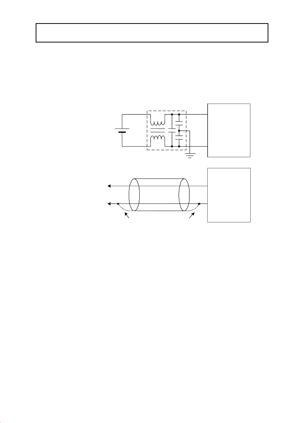
(2) When using a noise filter on the power supply, check that the filter is suitable for the supply voltage and
current ratings, and then attach the noise filter as close as possible to the K3GN.
<Examples of noise prevention schemes>
Line filter
24VDC
Power
supply
input
Digital Panel
Meter
Shielded cable
Digital Panel
Meter
Signal
input
Connect in the direction that
best reduces noise.
(3) If placed near the product, radios, TVs, or other wireless devices may suffer reception interference..
VII
Page 9

Alphabetic Characters for Setting Data
This manual uses the following alphabetic characters for setting data.
a b c d e f g h i j k l m
A B C D E F G H I J K L M
n o p q r s t u v w x y z
N O P Q R S T U V W X Y Z
VIII
Page 10

Table of Contents
PREFACE ................................................................................................................I
General Precautions..................................................................................................I
Other Informations ................................................................................................. II
Signal Words and Safety Notices .......................................................................... Ⅲ
Safety Precautions .................................................................................................IV
Installation and Noise Prevention Tips................................................................... V
Alphabetic Characters for Setting Data ................................................................. VI
CHAPTER 1 INTRODUCTION ............................................................. 1
1.1 Main Features.......................................................................................................... 2
1.2 Model Number Legend............................................................................................ 4
1.3 I/O Circuits.............................................................................................................. 5
1.4 Parts Name and Function......................................................................................... 8
CHAPTER 2 INSTALLATION AND CONNECTION.............................. 9
2.1 Installation............................................................................................................. 10
2.2 I/O Terminal Connections ..................................................................................... 12
CHAPTER 3 APPLICATION EXAMPLES........................................... 15
3.1 Monitoring the Remaining Quantity of Soup ........................................................ 16
3.2 Monitoring the Load Current of a Motor............................................................... 18
3.3 Monitoring the Quantity of Dust ........................................................................... 20
3.4 Monitoring the Internal Pressure of a Tank........................................................... 22
3.5 Monitoring the Rotational Speed of a Motor......................................................... 24
3.6 Using the Product as a Digital Indicator for PLC.................................................. 26
CHAPTER 4 INITIAL SETTING.......................................................... 29
4.1 Using the Product as a process meter .................................................................... 30
4.2 Using the Product as a Tachometer ....................................................................... 32
4.3 Using the Product as a Digital Indicator for PLC Data ......................................... 34
CHAPTER 5 OPERATION.................................................................. 37
5.1 Levels .................................................................................................................... 38
5.2 Moving among Levels........................................................................................... 39
5.3 Parameters ............................................................................................................. 42
5.4 Set Values.............................................................................................................. 44
5.5 Operation Level..................................................................................................... 45
5.6 Communication Writing Control........................................................................... 47
IX
Page 11

5.7 Key Protect Setting ................................................................................................48
5.8 Selecting an Input Type .........................................................................................50
5.9 Selecting an Analog Range....................................................................................51
5.10 Selecting an Input-pulse Frequency Range............................................................52
5.11 Specifying the Scaling Factor for Analog Input/Digital Data Display...................53
5.12 Specifying the Scaling Factor for Input Pulse Frequency...................................... 55
5.13 Specifying the Decimal Point Position ..................................................................58
5.14 Selecting the Output Operating Action..................................................................59
5.15 Performing Linear Output......................................................................................60
5.16 Specifying Communication Parameters.................................................................63
5.17 Clearing All Parameters.........................................................................................65
5.18 Specifying the Number of Measurements for Averaging ......................................66
5.19 Specifying the Function of the Event Input ...........................................................67
5.20 Specifying the Hysteresis.......................................................................................69
5.21 Specifying the Auto-zero Time..............................................................................71
5.22 Specifying the Startup Compensation Time ..........................................................73
5.23 Changing the Display Color...................................................................................75
5.24 Changing the Display Auto-return Time................................................................77
5.25 Changing the Move-to-Protect-Level Time...........................................................79
5.26 Changing the Send Waiting Time..........................................................................81
CHAPTER 6 FUNCTION DESCRIPTION .......................................... 83
6.1 Measurement..........................................................................................................84
6.2 Scaling ................................................................................................................... 86
6.3 Auto-zero/Startup Compensation...........................................................................88
6.4 Average Processing................................................................................................89
6.5 Event Input/Pulse Input..........................................................................................90
6.6 Process Value Hold................................................................................................ 91
6.7 Forced-zero ............................................................................................................ 92
6.8 Comparative Output...............................................................................................93
6.9 Hysteresis............................................................................................................... 94
6.10 Display Color Change............................................................................................ 95
CHAPTER 7 COMMUNICATIONS ..................................................... 97
7.1 Communication Protocols......................................................................................98
7.2 Data Format Structure............................................................................................99
7.3 Structure of Command/Response Text ................................................................101
7.4 Variable Area.......................................................................................................102
7.5 Read from Variable Area ...................................................................................103
7.6 Write to Variable Area ....................................................................................... 104
7.7 Operation Instructions..........................................................................................105
7.8 Setting Areas........................................................................................................ 106
7.9 Commands and Responses...................................................................................107
7.10 Variable Area Map...............................................................................................115
7.11 Communications Control Flow............................................................................ 118
7.12 Programming Example ........................................................................................123
X
Page 12

CHAPTER 8 USER CALIBRATION.................................................. 127
8.1 User Calibration .................................................................................................. 128
8.2 User Calibration Processes.................................................................................. 130
CHAPTER 9 TROUBLESHOOTING GUIDE .................................... 133
9.1 Error Indications.................................................................................................. 134
9.2 Troubleshooting Table......................................................................................... 135
APPENDIX ...................................................................137
Specifications ............................................................................................ 138
Parameter List............................................................................................ 142
ASCII Code Table...................................................................................... 143
XI
Page 13

Page 14

1.1 Main Features
INTRODUCTION
CHAPTER
1 INTRODUCTION
This chapter provides an overview of the product.
1.1 Main Features
1.2 Model Number Legend
1.3 I/O Circuits
Input Circuit Diagrams/Output Circuit Diagrams/
Internal Block Diagram
1.4 Parts Name and Function
・・・・・・・・・・・・・・・・・・・・・・・・・・・・・・・・・・・・・・・・・・・・
・・・・・・・・・・・・・・・・・・・・・・・・・・・・・・・・・・・・
・・・・・・・・・・・・・・・・・・・・・・・・・・・・・・・・・・・・・・・・・・・・・・
・・・・・・・・・・・・・・・・・・・・・・・・・・・・・・・・・・
2
4
5
8
1
Page 15
CHAPTER 1 INTRODUCTION
S
((8T(8(
((8T(8(
1.1 Main Features
INTRODUCTION
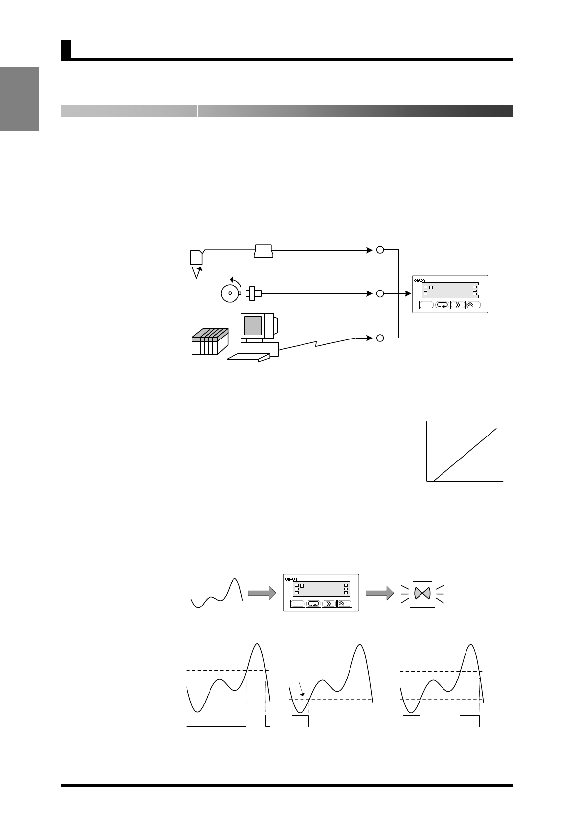
The K3GN is a digital panel meter that is capable of converting an input signal
into a digital value and displaying it on the main indicator.
The main futures of the product include the following.
Measurement
This feature measures an input signal and displays it as a digital value.
An analog value (voltage/current), a rotational speed (pulses), or digital data
received via communication function can be selected as an input signal.
PLC
PC
Voltage/current
ON/OFF
RS485
OUT1
OUT2
K3GN
SV
ZERO
HOLD
CMW
/ZERO
caling
This feature converts an input signal into a
desired physical value
The figure on the right shows a scaling example
Readout
100kPa
where input signals from a pressure sensor
ranging from 4 to 20 mA are converted into
values ranging from 0 to 100 (kPa). Scaling will
enable you to handle physical quantities easily
and intuitively.
0kPa
4mA
Input
20mA
Comparative
Output
This feature compares a scaled (process) value with a programmed OUT set value
and produces output according to the comparison result.
This is useful in monitoring various systems for malfunction or determining
whether products are within acceptance limits.
OUT1
OUT2
K3GN
SV
/ZERO
ZERO
HOLD
CMW
Three types of comparative outputs are available: those produced at the OUT
upper-limit value, the OUT lower-limit value, and both the OUT values.
OUT upper
limit value
OUT lower
limit value
OUT
lower
limit
value
OUT upper
limit value
Comparative output
Comparative output
produced at the OUT upper
limit value
Comparative output Comparative output
Comparative output
produced at the OUT lower
limit value
Comparative output produced at
the OUT upper and lower limit
values
2
Page 16

1.1 Main Features
/
INTRODUCTION
Process
Value Hold
Forced-zero
Display Color
Change
This feature enables a process value
to be held while the external event
input stays ON.
Process
value
The outputs are also retained.
HOLD input
This feature shifts a process value to zero, and can be used to evaluate and display
the deviation of a process value from a reference value.
The forced-zero function can be activated by using the
ZERO
key on the front
panel, via the event input terminal, or communications.
Process
value
Forced-zero value
(shifted value)
ZERO input
Measurement value
after executing the
forced-zero function
This feature allows programming of the display color. In the example shown
below, the display color is programmed so that it changes from green to red when
a comparative output turns ON. The display color can also be programmed so that
it changes red to green or is fixed to red or green.
Communi-cation
Red
T
8
OUT1 value
OUT2 value
T
8
1(781
Red
Green
T
8
1*005
1!236
This feature allows the host PC to read process values from the product or
read/write various parameter settings from/to the host PC.
The host PC provides logging of measured data and remote control to the product.
485
232C
T
((((8
8
T
((((8
8
T
((((8
8
3
Page 17
CHAPTER 1 INTRODUCTION
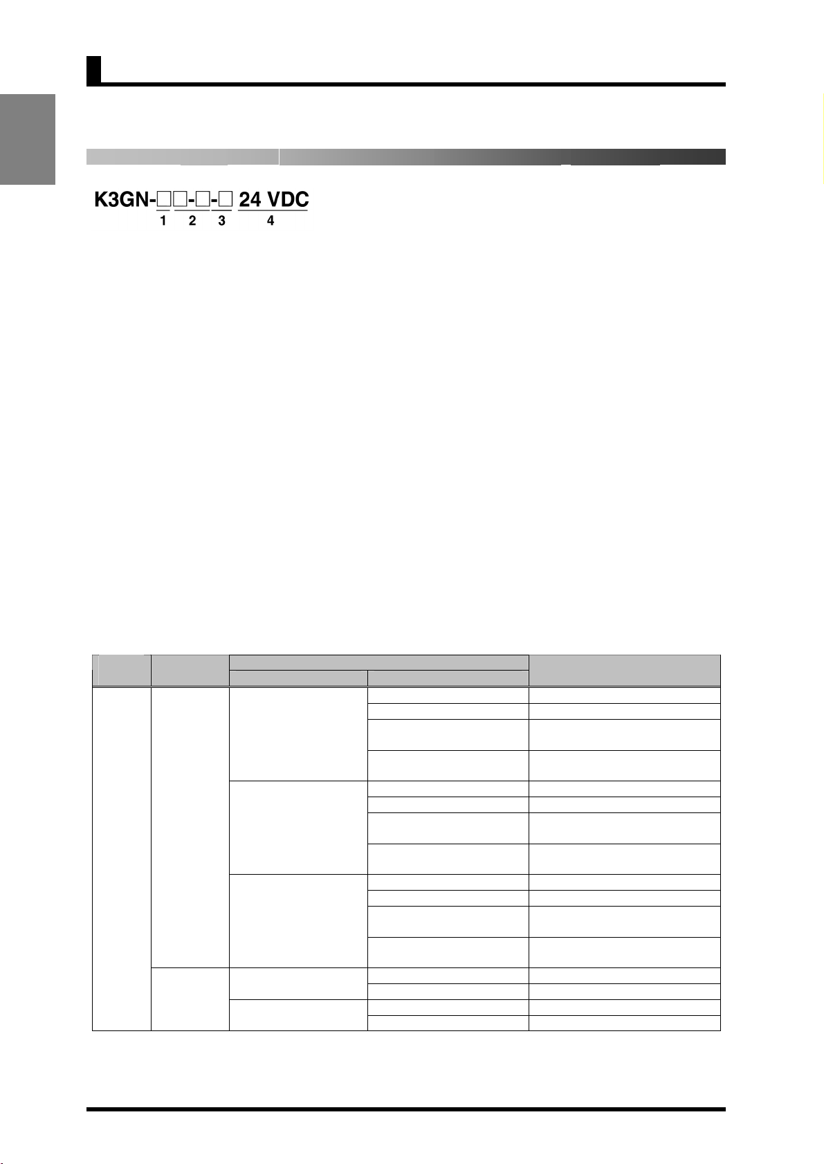
1.2 Model Number Legend
INTRODUCTION
1. Input Type
ND: DC voltage/current, NPN
PD: DC voltage/current, PNP
2. Output Type
C: 2 relay contact outputs (SPST-NO)
C-FLK: 2 relay contact outputs (SPST-NO) and RS-485
C-L1: 2 relay contact outputs (SPST-NO) and DC current (0 to 20 mA, 4 to 20 mA)
C-L2: 2 relay contact outputs (SPST-NO) and DC voltage (0 to 5 V, 1 to 5 V, 0 to 10 V)
T1: 3 transistor outputs (NPN open collector)
T1-FLK: 3 transistor outputs (NPN open collector) and RS-485
T1-L1: 3 transistor outputs (NPN open collector) and DC current (0 to 20 mA, 4 to 20 mA)
T1-L2: 3 transistor outputs (NPN open collector) and DC voltage (0 to 5 V, 1 to 5 V, 0 to 10 V)
T2: 3 transistor outputs (PNP open collector)
T2-FLK: 3 transistor outputs (PNP open collector) and RS-485
3. Option
None: None
-400: Normally energized relays
4. Supply Voltage
24 VDC: 24 VDC
List of Models
voltage
24 VDC
Note: Refer to page 6 for information on models with normally energized relays.
Input type
DC voltage,
DC current,
or NPN
input
DC voltage,
DC current,
or PNP
input
Judgement output Data transmission output
2 relay contact outputs
(SPST-NO)
2 relay contact outputs
(SPST-NO)
Normally energized
relays (See note.)
3 transistor outputs
(NPN open collector)
(SPST-NO)
3 transistor outputs
(PNP open collector)
Output type Supply
None K3GN-NDC 24 VDC
RS-485 K3GN-NDC-FLK 24 VDC
DC current (0 to 20 mA,
4 to 20 mA)
DC voltage (0 to 5 V,
1 to 5 V, 0 to 10 V)
None K3GN-NDC-400 24 VDC
RS-485 K3GN-NDC-FLK-400 24 VDC
DC current (0 to 20 mA,
4 to 20 mA)
DC voltage (0 to 5 V,
1 to 5 V, 0 to 10 V)
None K3GN-NDT1 24 VDC
RS-485 K3GN-NDT1-FLK 24 VDC
DC current (0 to 20 mA,
4 to 20 mA)
DC voltage (0 to 5 V,
1 to 5 V, 0 to 10 V)
None K3GN-PDC 24 VDC 2 relay contact outputs
RS-485 K3GN-PDC-FLK 24 VDC
None K3GN-PDT2 24 VDC
RS-485 K3GN-PDT2-FLK 24 VDC
Model
K3GN-NDC-L1 24 VDC
K3GN-NDC-L2 24 VDC
K3GN-NDC-L1-400 24 VDC
K3GN-NDC-L2-400 24 VDC
K3GN-NDT1-L1 24 VDC
K3GN-NDT1-L2 24 VDC
4
Page 18
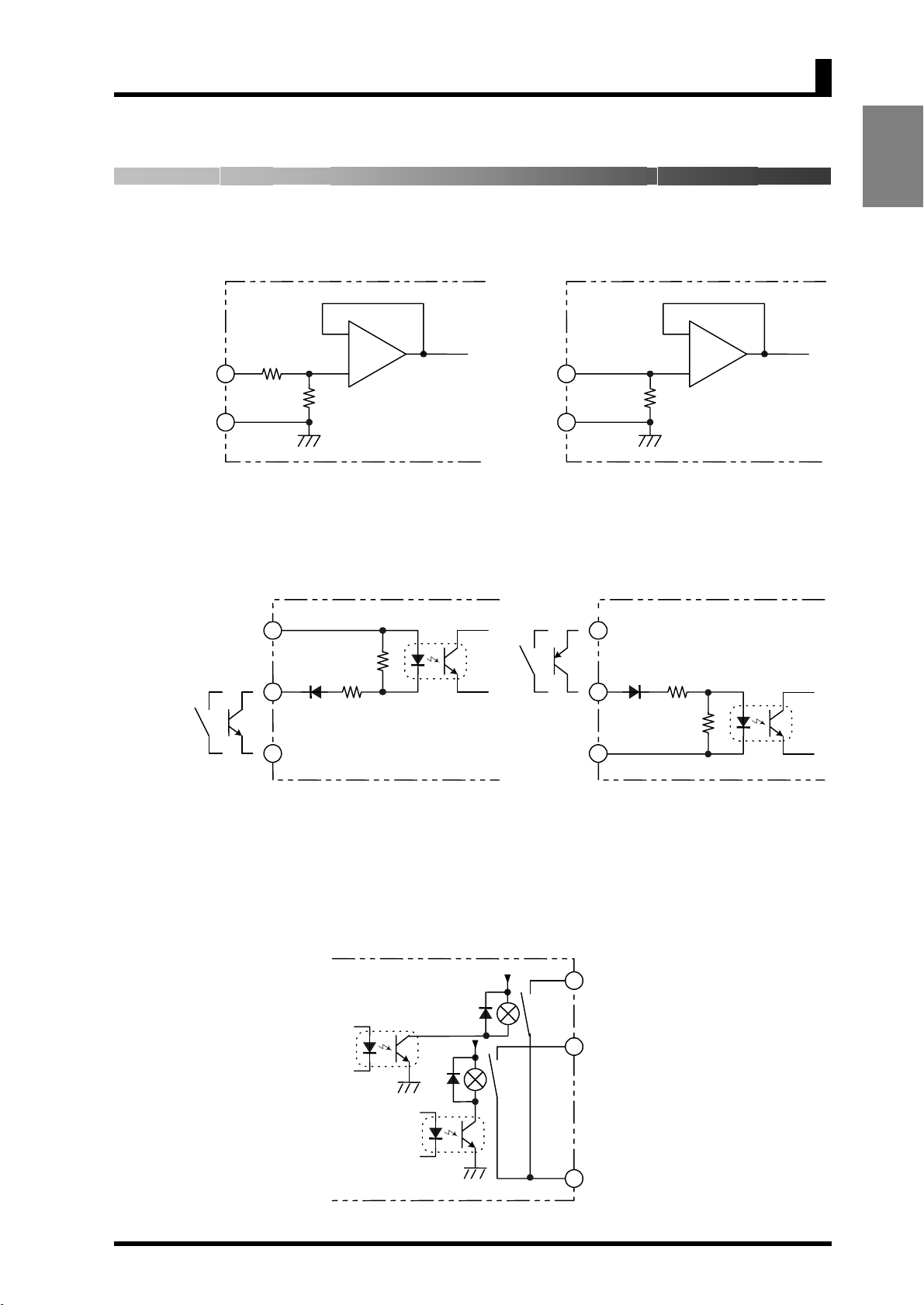
1.3 I/O Circuits
A
A
A
A
Input Circuit Diagrams
Analog Input
1.3 I/O Circuits
INTRODUCTION
Voltage
COM 4 5
Voltage input Current input
Event Input/Pulse Input
1
24VDC+
HOLD/ZERO
Pulse
24VDC-
3
2
NPN input PNP input
B
4.7K
2.35K
-
+
Ω
+B = 1M
Ω
-
D
To To
Ω
Current
6
5
COM
24VDC+
HOLD/ZERO
Pulse
24VDC-
+
Ω
60
1
Ω
2.35K
3
Ω
4.7K
2
D
Output Circuit Diagrams
Contact Output
5V
5V
OUT1
9
11
12
OUT2
COM
5
Page 19
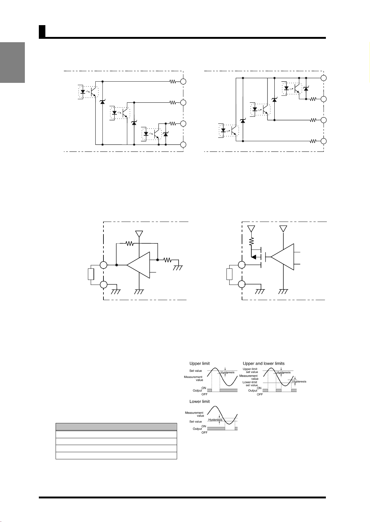
CHAPTER 1 INTRODUCTION
N
Transistor Output
INTRODUCTION
NPN output PNP output
8.2Ω
8.2Ω
8.2Ω
OUT1
9
PASS
10
OUT2
11
12
COM
8.2Ω
8.2Ω
8.2Ω
COM
12
OUT2
11
PASS
10
9
OUT1
Linear Output
-
-
5KΩ min.
+
7
L
+
500Ω max.
+
7
L
+
8
-
Linear voltage output
Models with Normally Energized
Relays K3GN-NDC-@-400 24 VDC
• The drive operation for the output relay is
reversed in these models.
• Relay contacts can be made open (i.e., OFF)
when comparative set values are being judged.
This is effective when constructing systems that
take failsafe measures into consideration.
List of Models
Models with Normally Energized Relays
K3GN-NDC-400 24 VDC
K3GN-NDC-FLK-400 24 VDC
K3GN-NDC-L1-400 24 VDC
K3GN-NDC-L2-400 24 VDC
8
-
Linear current output
Relation between Output Type and
Relay Output Operation
ote: If Upper/Lower Limit is
selected, the upper limit
and lower limit for the
comparative set value
can be set individually
and will be displayed
for OUT1 and OUT2.
6
Page 20
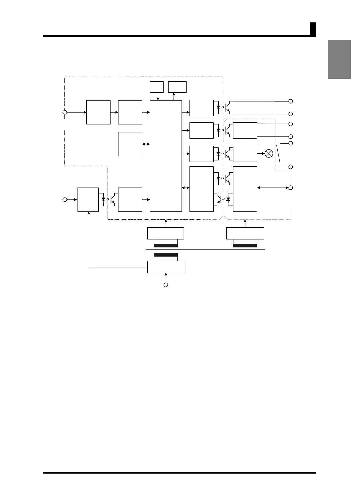
Internal Block Diagram
A
A
1.3 I/O Circuits
INTRODUCTION
nalog input
terminal
Event input/
pulse input
terminal
Key
Display
Control
circuit
Input circuit
input
D
convertor
EEPROM
Waveform
recitification
circuit
Microcomputer
Drive circuit
Drive circuit
Drive circuit
Drive circuit
Output
circuit
Output
circuit
Communi-
cation
driver
Constant-voltage
circuit 1
Constant-voltage
circuit 2
Transistor
output
*4
Linear current/
Voltage output
Contact
output
Communi-
cation
terminal
*2
*3
Power supply
circuit
Operation
power supply
*1 Available only for the product with transistor output
*2 Available only for the product with relay output
*3 Available only for the product with communication interface
*4 Available only for the product with linear current/voltage output
7
Page 21
CHAPTER 1 INTRODUCTION
r
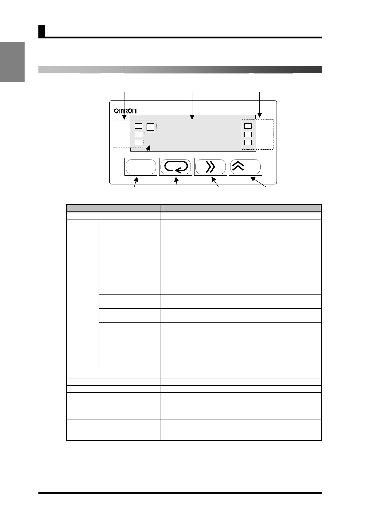
1.4 Parts Name and Function
INTRODUCTION
Level
indicato
Operation
indicator
sections
Operation indicator
section
K3GN
OUT1
OUT2
Name Function
Main indicator Displays a process value, parameter code, or set value.
(Comparative output 1)
(Comparative output 2)
(Forced-zero)
(Process value hold)
(Communication
Level indicator Indicates the current level.
Level key Use to change one level to another.
Mode key Use to select a parameter.
Shift key
Up/Zero key
SV
Level key Mode key Shift key Up/Zero key
OUT1
OUT2
SV
(Set value)
T
(Teaching)
ZERO
HOLD
CMW
writing)
T
8
(((( 8
Is on when comparative output 1 is ON, and off when
comparative output 1 is OFF.
Is on when comparative output 2 is ON, and off when
comparative output 2 is OFF.
Stays on while a set value is displayed or being changed, and off
at all other times.
Stays on while a set value that can be taught is displayed, and
blinks during teaching.
At the calibration level, stays on while a calibration value is
displayed, and blinks while the calibration value is read.
Stays off at all other times.
Is on when zero-shifting by forced-zero operation is active.
Turns off when forced-zero operation is canceled.
Stays on while the process value is held, and off at all other times.
Is on while data reading and writing via communication interface
are both enabled.
Is off while data writing via communication interface is disabled.
Data reading is enabled even if this indicator is off provided that
the product has the communication function.
If the product has no communication function, this indicator is
always off.
Use to check the set value of a parameter or enter the change state
when the parameter is displayed.
Use to select the digit that can be changed while shifting the set
value.
Use to change the set value in the change state.
Use to execute or cancel the forced-zero operation when a process
value is displayed.
Main indicator
Operation indicator
section
ZERO
HOLD
CMW
/ZERO
8
Page 22

AND
CONNECTION
CHAPTER
1.4 Parts Name and Function
2 INSTALLATION
INSTALLATION
AND CONNECTION
This chapter describes how to install and connect the product
before turning the power on.
2.1 Installation
2.2 I/O Terminal Connections
・・・・・・・・・・・・・・・・・・・・・・・・・・・・・・・・・・・・・・・・・・・・・・・
Dimensions/Panel Cutout Dimensions/
Installation Procedure
・・・・・・・・・・・・・・・・・・・・・・・・・・・・・・・・・
Terminal Arrangement/Terminal Connection
10
12
9
Page 23

CHAPTER 2 Installation and Connection
2.1 Installation
Dimensions
INSTALLATION
AND CONNECTION
Size of characters displayed
on the main indicator
8
24
35
7mm
3.6mm
44.8
48
3
(36.8)
80
22
Units in mm
Panel Cutout Dimensions
Separate mounting (units in mm) Gang mounting (units in mm)
60 min.
+0.6
45
40 min.
-0
+0.3
-0
22.2
Fit the product into a rectangular panel cutout, put the adapter on the product from
the rear end all the way to the panel, and tighten the screws of the adapter to
secure the product.
When gang-mounting the products, make sure the ambient temperature of the
product falls within the specified limits.
Mount to a panel that is 1 to 5 mm thick. Mounting the product to a thinner panel
will reduce the resistance to shock and vibration and may result in a malfunction
of the product.
(48 x No. of products -2.5)
The products cannot be made waterproof
when gang-mounted.
+1.0
-0
+0.3
-0
22.2
10
Page 24
AND
CONNECTION
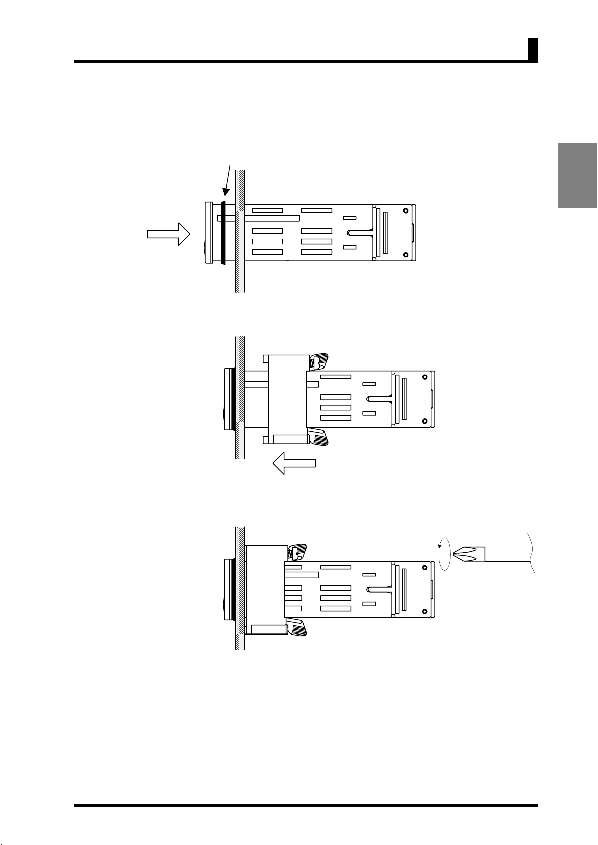
Installation Procedure
(1) Fit the product into a rectangular panel cutout.
(2) If you want to make the product waterproof, use the watertight packing as
shown in the figure below.
Note that the watertight packing is direction-sensitive.
(3) Put the adapter on the product from the rear end all the way to the panel.
2.1 Installation
INSTALLATION
(4) Tighten the two screws of the adapter in alternate order to a tightening torque
of 0.29 to 0.39 N·m.
11
Page 25
CHAPTER 2 Installation and Connection
x
x
A
A
A
r
A
A
2.2 I/O Terminal Connections
INSTALLATION
AND CONNECTION
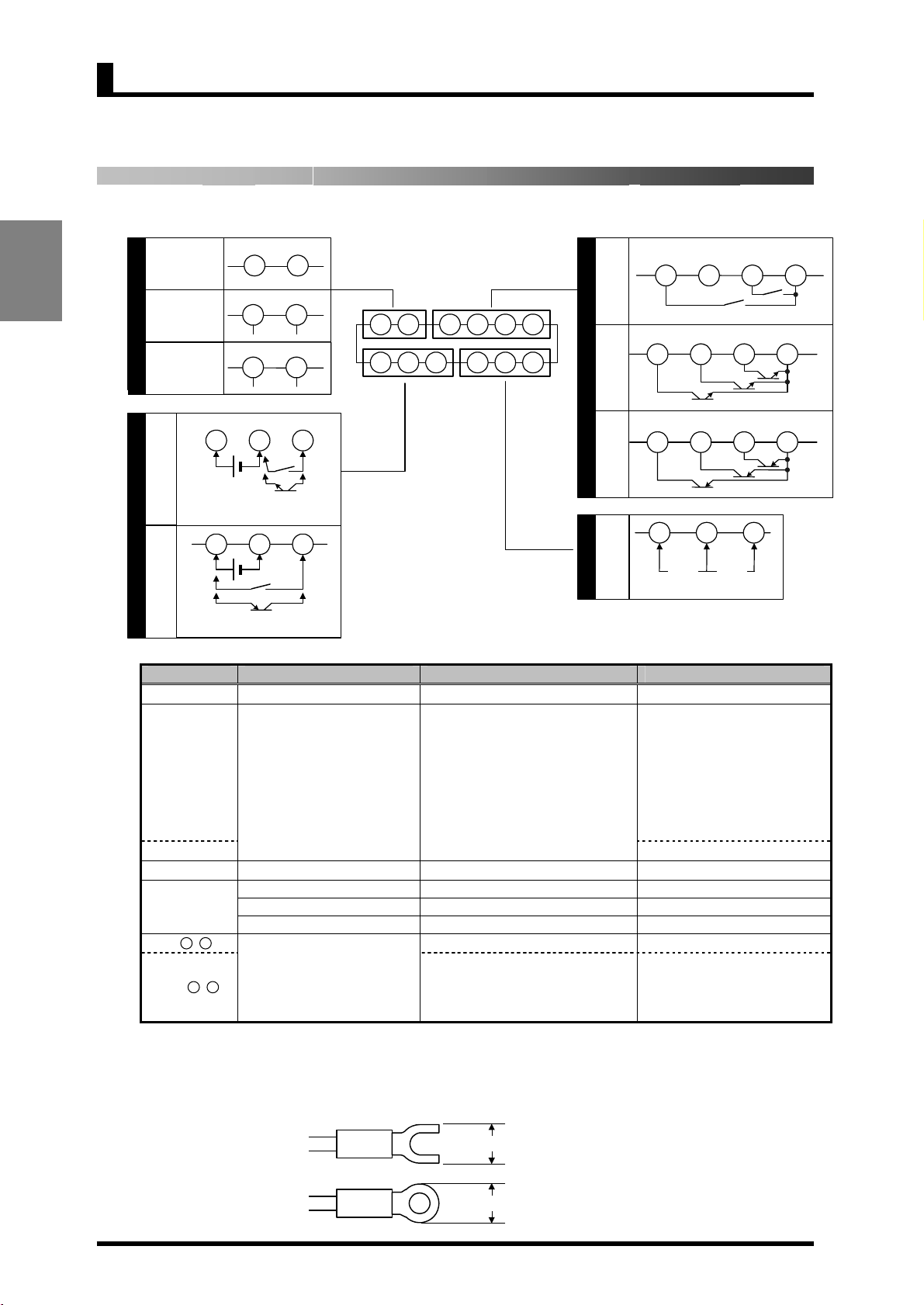
Terminal Arrangement
NC
NC
C
NPN
input
PNP
input
Without
communication
function
With
communication
function
With linear
output
Control voltage
24VDC
Control
voltage
24VDC
1
1
Event input or
pulse input
7
8
RS485
7
8
B (+)
Current/Voltage
7
8
(+)
2
Event input or
pulse input
2
C
(-)
(-)
3
3
7 8 9 10 11 12
1 2 3 4 5 6
Relay
output
D
NPN
tran-
output
D
B
sistor
PNP
tran-
sisto
output
OUT1 OUT2 COM
OUT1 OUT2 COMPAS S
9 10 11 12
OUT1 OUT2 COMPAS S
9 10 11 12
NC
9 10 11 12
4 5 6
nalog
input
B
Vol tag e
COM
Current
nalog input
Terminal No. Name Description Applicable model
-
Operation power supply Operation power supply terminals All models
Depending on parameter setting:
Hold the process value.
•
-
Event input
or
pulse contact/
input
Serve as input terminals for the
•
forced-zero or forced-zero
cancel operation.
Serve as pulse input terminals
•
K3GN-ND_-_ 24VDC
when the input type is set to
"pulse".
-
-
K3GN-PD_-_ 24VDC
Analog input Voltage/current analog terminals All models
Communication RS-485 communication terminals K3GN-_D_-FLK 24VDC
-
Linear current output Linear current output K3GN-___-L1 24VDC
Linear voltage output Linear voltage output K3GN-___-L2 24VDC
11-12
Provide comparative output. K3GN-_DC-_ 24VDC
Provide PASS output in addition
11-12
Comparative output
to OUT1/OUT2 (comparative
output 1/2) when the product is of
K3GN-NDT1-_ 24VDC
K3GN-PDT2-_ 24VDC
transistor output type.
Terminal Connection
Wire the terminals using M3 crimp contacts of the type shown below.
5.8 mm ma
5.8 mm ma
12
Page 26
AND
CONNECTION
Power Supply
2.2 I/O Terminal Connections
7 8 9 10 11 12
1 2 3 4 5 6
Connect the following power supply to terminals and .
Supply voltage: 24VDC
Operating voltage range: 85 to 110% of the rated voltage
Power consumption: 2.5W (at max. load)
Note that, when turned on, the product will require the operation power supply to
have more power supply capacity than rated.
If multiple products are used, the power supply must be able to afford to supply
power to the products.
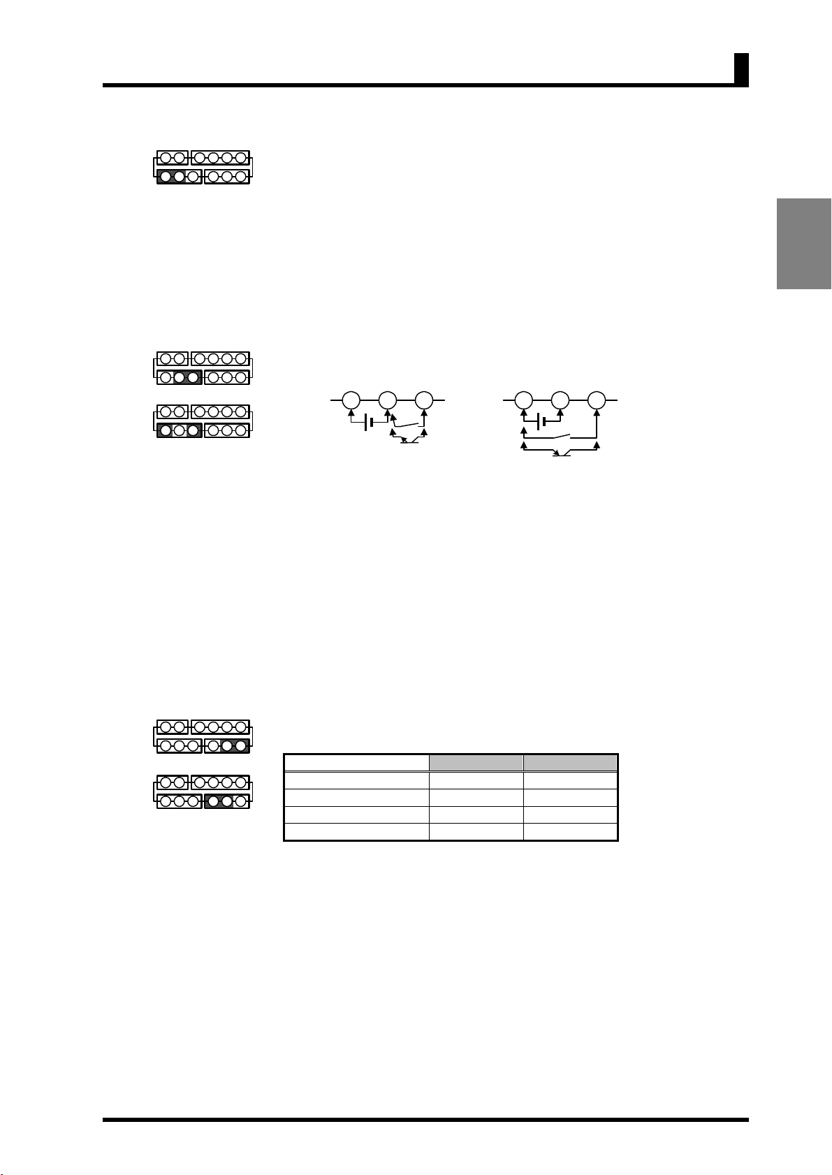
Event Input or Pulse Input
7 8 9 10 11 12
1 2 3 4 5 6
NPN input
7 8 9 10 11 12
1 2 3 4 5 6
PNP input
Apply the event or pulse signal to terminals and if the product is of NPN
input type, or terminals
Control power
24VDC
The input equipment connected to these terminals must meet the following
conditions.
Transistor output ON residual current: 2.5V max.
OFF leakage current: 0.1 mA max.
Current leakage with
transistor turned ON: 15 mA min.
Relay output Load current: 5 mA max.
1 2 3
Event or
pulse input
NPN input type
and if the product is of PNP input type.
2
3
Control power
24VDC
1
Event or
pulse input
PNP input type
INSTALLATION
Analog Input
7 8 9 10 11 12
1 2 3 4 5 6
Current input
7 8 9 10 11 12
1 2 3 4 5 6
Voltage input
The following table shows the analog ranges and applicable analog input
terminals.
Analog range Positive side Negative side
4 to 20 mA/0 to 20 mA
1 to 5V/0 to 5V
±5V
±10V
The maximum absolute ratings for analog input are as follows.
Be careful that these ratings must not be exceeded even for a moment.
4 to 20 mA/0 to 20 mA: ±30 mA
1 to 5V/0 to 5V: ±13.5V
±5V: ±13.5V
±10V: ±26V
13
Page 27
CHAPTER 2 Installation and Connection
t
Communication
7 8 9 10 11 12
1 2 3 4 5 6
Connect the communication cable to terminals and if using the
communication function.
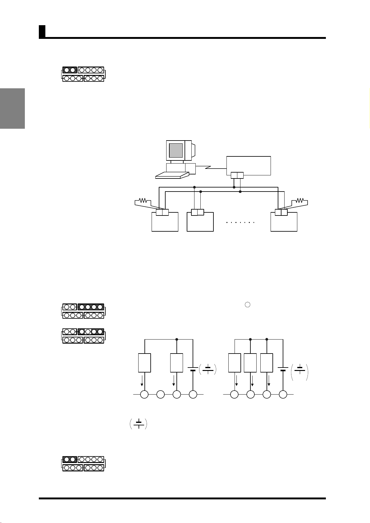
RS-485 connections can be one-to-one or one-to N. A maximum of 32 units
(including the host computer) can be connected in one-to-N systems.
The total length of the communication cables should be up to 500 m.
Use shielded twisted-pair cables (AWG 28 or thicker) as the communication
INSTALLATION
AND CONNECTION
cables.
Be sure to turn ON the terminator switches only in the devices at each end of the
transmission line.
Terminator
120Ω(1/2Ω)
7 8
(B) (A)
K3GN
(No. 1)
7
(B) (A)
K3GN
(No. 2)
RS232C
8
RS232C-RS485
interface convertor
+ -
7 8
(B) (A)
K3GN
(No. 31)
Terminator
120Ω(1/2Ω)
Match the communications format of the K3GN and the host computer. If a
one-to-N system is being used, be sure that the communications formats of all
devices in the system (except individual unit numbers) are the same.
Chapter 7 explains how to set the K3GN communication format. Refer to your
computer's manual for details on changing its communications settings.
Comparative Output
7 8 9 10 11 12
1 2 3 4 5 6
Transistor outpu
7 8 9 10 11 12
1 2 3 4 5 6
Relay output
Comparative output is produced at terminals to 12.
If the product is of relay output type, terminal
Loads connected to the product and the power supply for the loads must be rated
as follows.
The
indicated by the arrows.
Linear Output
7 8 9 10 11 12
1 2 3 4 5 6
Linear currents and voltages are output between terminals 7 to 8. Contact a load
within the specified range.
is not used.
Load
1A
max.
9 10 11 12
OUT1 OUT2 COMNC
1A
Relay output type Transistor output type
max.
Load
30VDC max.
Load
max.
max.
50 mA
50 mA
9 10 11 12
OUT1 OUT2 COMPASS
Load
max.
50 mA
Load
24VDC max.
connection causes the current to flow in the direction opposite to
PNP
14
Page 28

EXAMPLES
CHAPTER
3 APPLICATION
2.2 I/O Terminal Connections
EXAMPLES
This chapter shows some examples of product applications.
3.1 Monitoring the Remaining Quantity of Soup
3.2 Monitoring the Load Current of a Motor
3.3 Monitoring the Quantity of Dust
3.4 Monitoring the Internal Pressure of a Tank
3.5 Monitoring the Rotational Speed of a Motor
3.6 Using the Product as a Digital Indicator for PLC
・・・・・・・・・・・・・・・・・・・・・・・・・・・・
・・・・・・・・・・・・・・・・・
・・・・・・・・・・・・・・・・・・・・
・・・・・・・・・・・・・・・・・・
・・・・・・・・・・・・・・・・・
・・・・・・・・・・・・・
16
18
20
22
24
26
APPLICATION
15
Page 29
CHAPTER 3 APPLICATION EXAMPLES
g
3.1 Monitoring the Remaining Quantity of Soup
EXAMPLES
APPLICATION
Application
Wirin
100%
20%
4 to 20mA
Remaining
quantity of soup
Replenish
Cup (L)
Cup (M)
Cup (S)
K3GN-NDC
Comparative output 1
(lower-limit action)
Ultrasonic sensor
E4PA-LS50-M1
60mm ~ 500mm
60mm
500mm
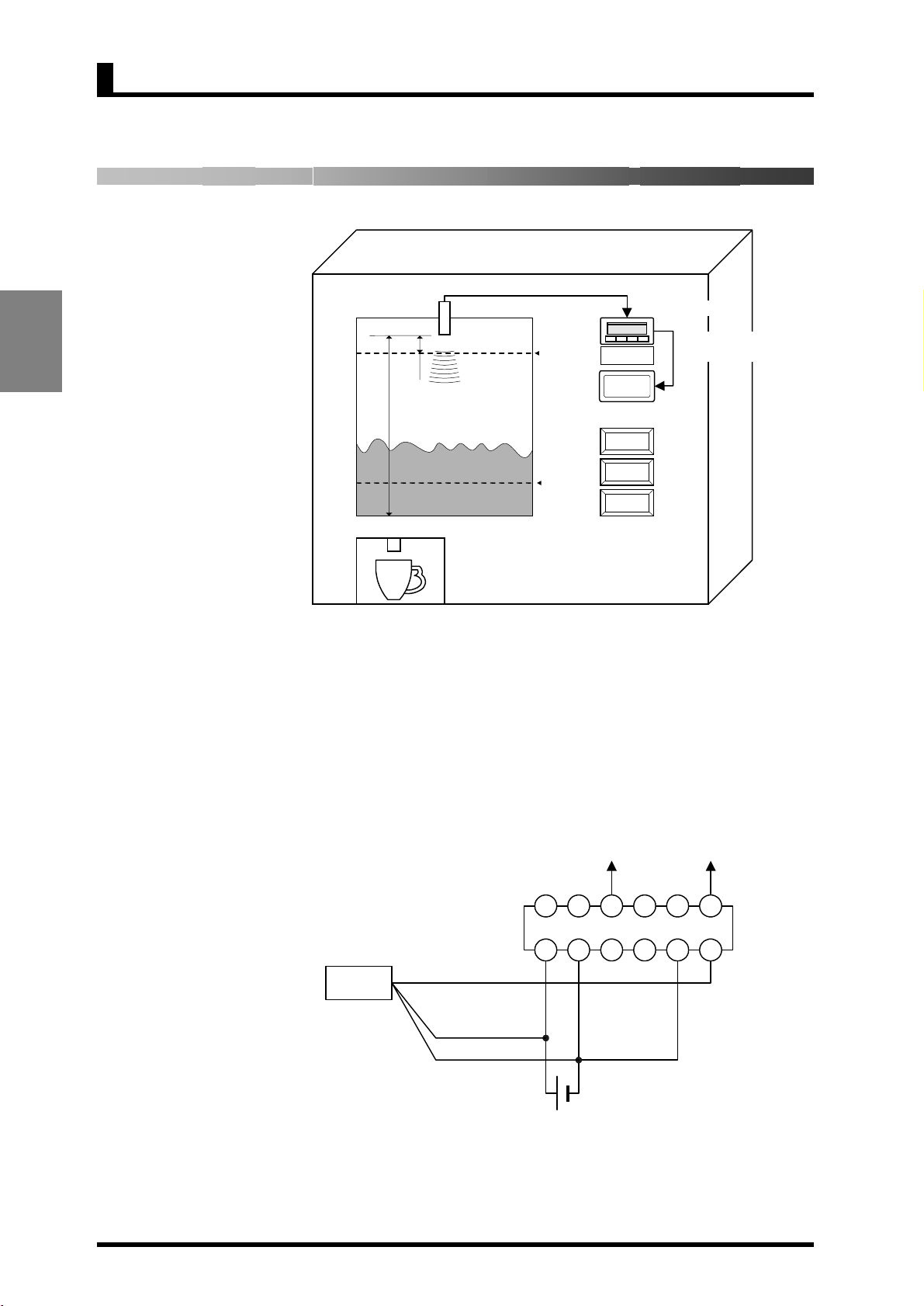
• The remaining quantity of soup is monitored.
• The soup level is measured with an ultrasonic displacement sensor.
• The K3GN indicates the remaining quantity of soup on a percentage basis.
• Four measurements are averaged for stable indication.
• Comparative output 1 is produced as a lower-limit action signal. When the
remaining quantity of soup reaches 20% (lower limit), the “Replenish” indicator
turns on.
Comparative output 1
COM
7 8 9 10 11 12
Ultrasonic displacement
sensor
Black
1 2 3 4 5 6
4 to 20mA
Brown (+)
Blue (-)
Operation
power supply
K3GN-NDC
24VDC
COM
Current
input
16
Page 30
EXAMPLES
g
Parameter Settin
Operation
3.1 Monitoring the Remaining Quantity of Soup
Set the parameters of the K3GN as follows.
Level Parameter Set value
in-t analg
range 4-20
inp.1 4.00
Initial setting
Advanced-function setting
Operation setting
dsp.1 100
inp.2 20.00
dsp.2 0
dp ,,,,,
out1.t lo
avg 4
out1 20
Set the analog output characteristic mode of the sensor to “decrease”. For details
on sensor setting, refer to the Operation Manual for the sensor.
Remaining quantity
of soup
APPLICATION
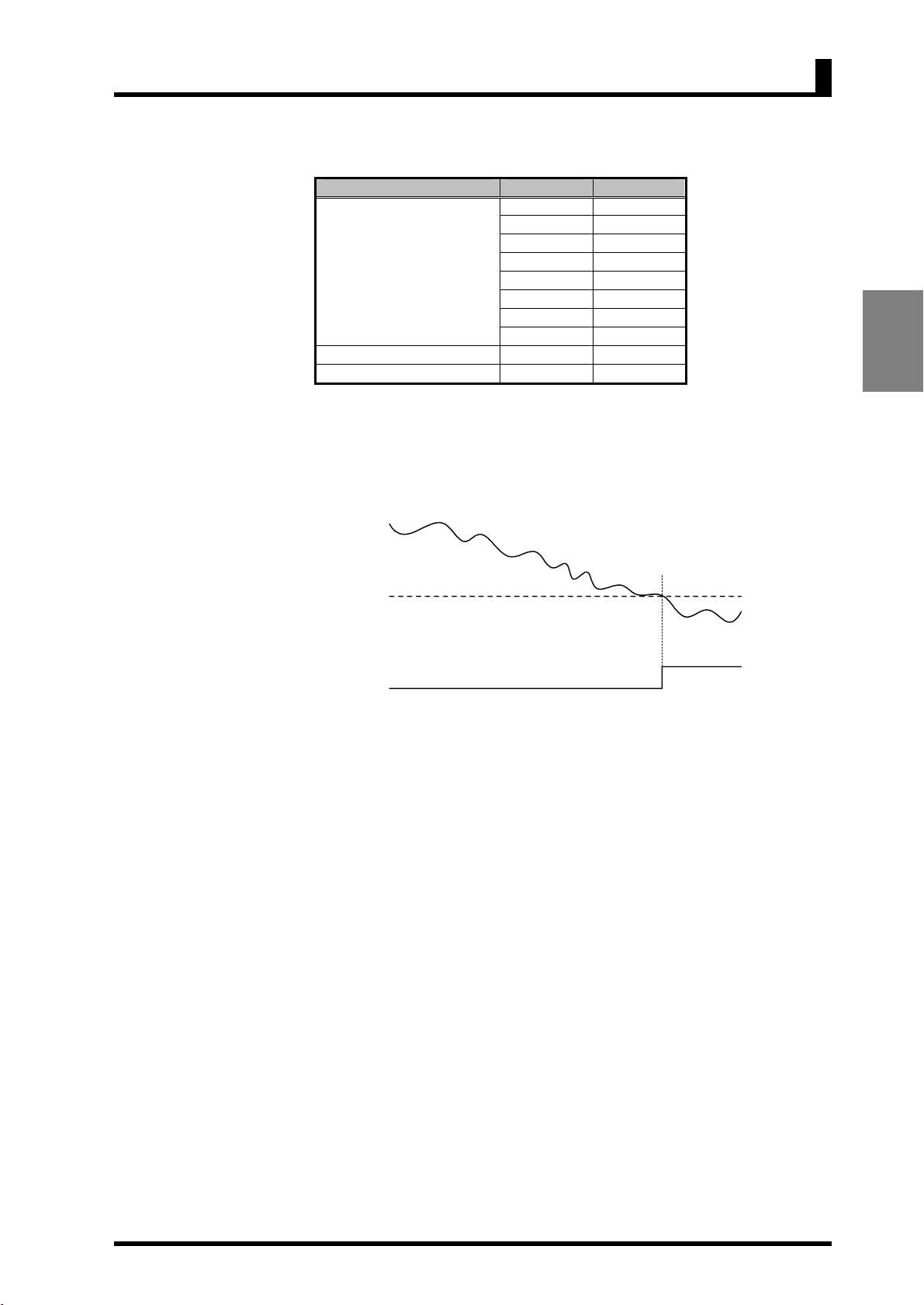
OUT1 lower
limit value
(20)
Comparative
output 1
• Comparative output 1 turns on when the remaining quantity of soup decreases to
20%.
17
Page 31

CHAPTER 3 APPLICATION EXAMPLES
g
3.2 Monitoring the Load Current of a Motor
EXAMPLES
APPLICATION
Application
Wirin
0 to 10A AC
Electro-
magnetic
relay
Power supply
10:1 current
transformer
0 to 1A 4 to 20mA
Signal input
Current transformer
K3FK-CE-1A-R
24VDC
power supply
K3GN
OUT1
OUT2
SV
8
K3GN-NDC
Comparative
(
(
( ( 8
/ZERO
ZERO
HOLD
CMW
output 1
(upper-limit action)
Comparative
output 2
(lower-limit action)
• The load current of a motor is monitored.
• A 10:1 current transformer is used to detect the motor current.
• The current transformer K3FK-CE-1A-R is used to adapt the input current to a
K3GN analog range.
• The K3GN indicates the load current in units of amperage to two decimal places.
• Comparative output 1 is used to generate an upper-limit action signal and
comparative output 2 is used to generate a lower-limit action signal.
• The OUT upper-limit value is set to 6.00A and the OUT lower-limit value is set
to 3.00A.
Comparative
output 1
Comparative
output 2
COM
Line side
K
L
Load side
k
l
Current protector
K3FK-CTM
1
3
2
4
7
8
K3FK-CE-1A-R
Signal
output
7 8 9 10 11 12
K3GN-NDC
1 2 3 4 5 6
+
-
+
Operation
power
supply
-
24VDC
COM
Current
input
18
Page 32

3.2 Monitoring the Load Current of a Motor
EXAMPLES
g
A
Parameter Settin
Operation
Set the parameters of the K3GN as follows.
Level Parameter Set value
in-t analg
range 4-20
inp.1 4.00
dsp.1 0
Initial setting
inp.2 20.00
dsp.2 1000
dp ,,,.,,
out1.t hi
out2.t lo
Operation setting
out1 6.00
out2 3.00
For details on the parameters, refer to CHAPTER 5 OPERATION.
Signal input
OUT1 value
(Upper limit: 6.00)
APPLICATION
OUT2 value
(Lower limit: 3.00)
Load current
Measurement
Indication
Comparative
output 1
Comparative
output 2
pprox.
1 sec.
Current value indication
• Turning the power on causes inrush current to flow through the motor. But the
K3GN does not produce superfluous output in response to the inrush current
because it does not perform measuring operation for approx. one second after
turn-on.
• Comparative output 1 turns on when the current flowing through the motor
reaches 6.00A.
Comparative output 2 turns on when the current flowing through the motor
decreases to 3.00A.
19
Page 33

CHAPTER 3 APPLICATION EXAMPLES
g
A
A
3.3 Monitoring the Quantity of Dust
EXAMPLES
APPLICATION
Crusher
Application
Wirin
To the air
0 to 1500ppm
Comparative output 1
(upper-limit action)
Crusher power
reduction command
Comparative output 2
(upper-limit action)
Crusher stop command
Dust collector
4 to 20mA
nalog photoelectric
sensor E3SA
K3GN
OUT1
OUT2
SV
8
(
(
K3GN-NDC
( ( 8
ZERO
HOLD
CMW
/ZERO
• The quantity of dust exhausted from a dust collector into the air is monitored.
• The analog photoelectric sensor E3SA is used to detect the quantity of dust.
• A dust quantity of 0 to 1500 ppm corresponds to an E3SA output of 4 to 20 mA.
• The K3GN indicates the quantity of dust in units of ppm.
• Comparative output 1 is used to generate an upper-limit action signal that
reduces the crusher power.
• Comparative output 2 is used to generate another upper-limit action signal that
stops the crusher.
• The OUT 1 upper-limit value is 800 ppm and the OUT2 upper-limit value is
1000 ppm.
• Eight measurements are averaged for stable indication.
• The hysteresis is set to 10 for stable output in the vicinity of the OUT set values.
Comparative
K3GN-NDC
COM
output 2
COM
Current
input
nalog photoelectric
sensor E3SA
Stripes of orange/purple
Brown (+)
Blue (-)
Black
4 to 20mA
Operation
power supply
Comparative
output 1
7 8 9 10 11 12
1 2 3 4 5 6
24VDC
20
Page 34

3.3 Monitoring the Quantity of Dust
EXAMPLES
g
Parameter Settin
Operation
Set the parameters of the K3GN as follows.
Level Parameter Set value
in-t analg
range 4-20
inp.1 4.00
dsp.1 0
Initial setting
inp.2 20.00
dsp.2 1500
dp ,,,,,
out1.t hi
out2.t hi
avg 8
Advanced-function setting
hys1
10
hys2 10
Operation setting
out1 800
out2 1000
For details on the parameters, refer to CHAPTER 5 OPERATION.
OUT2 value
(Upper limit: 1000)
OUT1 value
(Upper limit: 800)
Hysteresis
APPLICATION
Dust quantity
Comparative
output 1
Comparative
output 2
• Comparative output 1 turns on when the dust quantity reaches 800 ppm.
• When comparative output 1 turns on, the crusher power is reduced until the dust
quantity decreases to within the specified range.
• Comparative output 2 turns on when an accident causes a sudden increase in
dust quantity to 1000 ppm.
• When comparative output 2 turns on, it provides an emergency stop to the
crusher.
21
Page 35

CHAPTER 3 APPLICATION EXAMPLES
g
( (
8
T
(
3.4 Monitoring the Internal Pressure of a Tank
EXAMPLES
APPLICATION
Application
Wirin
Tank
0 to 980kPa
Pressure sensor
E8AA-M10
4 to 20mA
K3GN
OUT1
OUT2
SV
K3GN-NDC-FLK
RS485 RS232C
ZERO
HOLD
8 (
CMW
/ZERO
Host PC
• The internal pressure of a tank is monitored.
• The pressure sensor E8AA-M10 is used to detect the pressure in the tank.
• A pressure of 0 to 980 kPa corresponds to an E8AA-M10 output of 4 to 20 mA.
• The K3GN indicates the pressure in units of kPa to one decimal place.
• The communication function of the K3GN enables remote monitoring of the
pressure on the host PC.
• The status of comparative outputs is read by the host PC at a remote site.
• Comparative output 1 turns on when the pressure reaches 550.0 kPa, which
generates an upper-limit action signal.
• Comparative output 2 turns on when the pressure decreases to 100.0 kPa, which
generates a lower-limit action signal.
To host PC
via RS-485
B(+) A(-)
7 8 9 10 11 12
Pressure sensor
E8AA-M10
Black
1 2 3 4 5 6
4 to 20mA
Brown (+)
Blue (-)
Operation
power supply
K3GN-NDC-FLK
COM
24VDC
Current
input
22
Page 36

3.4 Monitoring the Internal Pressure of a Tank
EXAMPLES
g
A
A
Parameter Settin
Operation
Set the parameters of the K3GN as follows.
Level Parameter Set value
in-t analg
range 4-20
inp.1 4.00
dsp.1 0
Initial setting
inp.2 20.00
dsp.2 9800
dp ,,,,.,
out1.t hi
out2.t lo
u-no 1
Communication
setting
bps 9.6
len 7
sbit 2
prty even
Operation setting
out1 550.0
out2 100.0
Set the communication parameters according to the host PC setting.
For details on the parameters, refer to CHAPTER 5 OPERATION.
APPLICATION
OUT1 value
(Upper limit: 550.0)
Tank pressure
OUT2 value
(Lower limit: 100.0)
MRC
SRC
"01"
MRC
"01"
MRC
"01"
MRC
"01"
"01"
SRC
"01" "0000"
SRC
"01"
SRC
"01" "0000"
Command 1
Response 1 "00000400"
Command 2
Response 2 "00000100"
534.2kPa
Command 1
Response 1
Variable
type
"C0" "0001"
Response code Current value
Variable
type
"C0" "0001"
Response code Current value
ddress Bit position
"00" "0002"
"000014DE"
14DEH (5342 in decimal)
ddress Bit position
"00" "0002"
"00001638"
1638H (5688 in decimal)
568.8kPa
Command 2
Response 2
No. of elements
Status
(PASS output ON)
No. of elements
Status
(Comparative output 1 ON)
• The host PC reads the current value and the status from the K3GN at regular
intervals.
Of command and response frames, only text fields are shown in the above figure.
For details on communications, refer to CHAPTER 7 COMMUNICATIONS.
23
Page 37

g
( ( 8
T
(
(
( ( 8
T
(
(
3.5 Monitoring the Rotational Speed of a Motor
EXAMPLES
APPLICATION
CHAPTER 3 APPLICATION EXAMPLES
Application
Electro-
magnetic
relay
0 to 10A AC
Power supply
Current
transformer
10:1
0 to 1A 4 to 20mA
Signal input
Current transformer
K3FK-CE-1A-R
Proximity sensor
E2E-X1R5E1
24VDC
power supply
K3GN
OUT1
OUT2
8
SV
K3GN-NDC
K3GN
OUT1
OUT2
SV
8
K3GN-NDC
Comparative
ZERO
HOLD
/ZERO
CMW
output 1
(upper-limit action)
Comparative
output 2
(lower-limit action)
Comparative
/ZERO
CMW
ZERO
HOLD
output 1
(upper-limit action)
Comparative
output 2
(lower-limit action)
Wirin
• In addition to the load current monitored in the application shown in Section 3.2,
the rotational speed of a motor is also monitored with an additional K3GN.
• A four-toothed wheel is installed on the motor shaft to allow detection of its
rotational speed.
• The proximity sensor E2E-X1R5E1 converts motor shaft rotations to on/off
pulses.
• The K3GN indicates the rotational speed in terms of rpm.
• A startup compensation timer is used to prevent superfluous output from being
produced until the motor reaches a designated speed (for five seconds after
startup).
• Comparative output 1 is used to generate an upper-limit action signal.
Comparative output 2 is used to generate a lower-limit action signal.
• The OUT1 upper-limit value is set to 3500 rpm and the OUT2 lower-limit value
to 1000 rpm.
• The auto-zero function is used to enhance the lower-limit response.
(A speed of 150 rpm or less is automatically shifted to zero).
Proximity sensor
E2E-X1R5E1
Comparative
output 1
7 8 9 10 11 12
1 2 3 4 5 6
Black
Brown (+)
Blue (-)
K3GN-NDC
Pulse input
Comparative
output 2
COM
Operation
power supply
24VDC
24
Page 38

EXAMPLES
Parameter Settin
g
Operation
3.5 Monitoring the Rotational Speed of a Motor
Set the parameters of the K3GN as follows.
Level Parameter Set value
in-t pulse
p-fre 5k
inp 1000
Initial setting
dsp 15000
dp ,,,,,
out1.t hi
out2.t lo
Advanced-function setting
Operation setting
auto.z
0.1
s-tmr 5.0
out1 3500
out2 1000
For details on the parameters, refer to CHAPTER 5 OPERATION.
Signal input
APPLICATION
OUT1 value
(Upper limit: 3500)
OUT 2 value
(Lower limit: 1000)
Motor speed
5 sec.
Measurement
Indication
Comparative
output 1
Comparative
output 2
Current value indication
• The startup compensation timer works for five seconds after the motor power is
turned on. This prevents superfluous output from being produced by the
K3GN.
• Comparative output 1 turns on when the motor speed reaches 3500 rpm.
Comparative output 2 turns on when the motor speed decreases to 1000 rpm.
25
Page 39

g
g
A
( ( 8
T
(
(
3.6 Using the Product as a Digital Indicator for PLC
EXAMPLES
APPLICATION
CHAPTER 3 APPLICATION EXAMPLES
Application
RS232C RS485
PLC
• The K3GN is used as a digital indicator for PLC data.
• The display color of the K3GN main indicator is set to “always green”.
• The process value is displayed without scaling.
Wirin
To PLC
via RS-485
K3GN
OUT1
OUT2
SV
8
K3GN-NDC-FLK
ZERO
HOLD
CMW
/ZERO
Parameter Settin
B(+)
7 8 9 10 11 12
1 2 3 4 5 6
Control power
supply
(-)
K3GN-NDC-FLK
24VDC
Set the parameters of the K3GN as follows.
Level Parameter Set value
in-t rmt
inp.1 :9999
Initial setting
dsp.1 :9999
inp.1 99999
dsp.1 99999
dp ,,,,,
u-no 1
Communication setting
bps 9.6
len 7
sbit 2
prty even
Advanced-function setting
color
grn
Set the communication parameters according to the host PC setting
For details on the parameters, refer to CHAPTER 5 OPERATION.
26
Page 40

3.6 Using the Product as a Digital Indicator for PLC
EXAMPLES
A
A
A
A
Operation
1 2 3 4
"-53" "11342" "28500" "54321"
Update of input value
Command
Command
Command
Command
Indication
MRC
1
"01"
MRC
2
"01"
MRC
3
"01"
MRC
4
"01"
Variable
SRC
"02" "C2" "0000"
Variable
SRC
"02" "C2" "0000"
Variable
SRC
"02" "C2" "0000"
Variable
SRC
"02" "C2" "0000"
type
type
type
type
-53
ddress
ddress
ddress
ddress
11342
Bit
position
"00" "0001"
Bit
position
"00" "0001"
Bit
position
"00" "0001"
Bit
position
"00" "0001"
28500 54321
No. of elements
No. of elements
No. of elements
No. of elements
APPLICATION
Current value
"FFFFFFCB"
FFFFFFCBH (-53 in decimal)
Current value
"00002C4E"
2C4EH (11342 in decimal)
Current value
"00006F54"
6F54H (28500 in decimal)
Current value
"0000D431"
D431H (54321 in decimal)
27
Page 41

Page 42

3.6 Using the Product as a Digital Indicator for PLC
SETTING
CHAPTER
4 INITIAL SETTING
Typical applications of the product include a process meter, a
tachometer, or an indicator of digital data from PLC/PC.
This chapter explains the flow of initial setting for each of these
applications.
4.1 Using the Product as a process meter
4.2 Using the Product as a Tachometer
4.3 Using the Product as a Digital Indicator
・・・・・・・・・・・・・・・・・・・・・・・・
・・・・・・・・・・・・・・・・・・・・・・・・・
・・・・・・・・・・・・・・・・・・・・・
INITIAL
30
32
34
29
Page 43

CHAPTER 4 INITIAL SETTING
4.1 Using the Product as a process meter
The following example shows the flow of initial setting for the product that is used
as a process meter.
Setting example:
Input signals ranging from 1 to 5V is scaled to readouts ranging from 0 to
100 kg.
Comparative output 1 is produced when the process value (readout) reaches
70.0 kg.
Comparative output 2 is produced when the process value (readout)
decreases to 50.0 kg.
Readout
100.0kg
0.0kg
Comparative
output 2
Input signal1.000V 5.000V
50.0kg
Normal
range
70.0kg
Comparative
output 1
INITIAL
SETTING
Note
The input type, analog range,
scaling factor, and decimal
point position should be set
in this order.
Otherwise, auto-initialization
of parameters may result in a
failure in parameter setting.
If you specify the scaling
factor and then the input
type, for example, the analog
range and the scaling factor
are initialized automatically.
Flow of Initial Setting
A. Check wiring for correct connection and power the product on.
The product is factory set to have an analog input range of 4 to 20 mA.
If an input that falls outside this default range is received, the main
indicator of the product will read “s.err” and blink, indicating an
“input range over” error occurs.
B. Set “input type” to “analog”.
1. Make sure the main indicator displays a process value (the product is
at the operation level).
Then press the L key and hold it down for at least one second.
The product will move to the initial setting level.
2. Set parameter “in-t” to “analg”.
C. Set “analog range” to “1 ~ 5V”.
1. Set parameter “range” to “1-5”.
D. Specify the scaling factor.
1. Set parameter “inp.1” to “1.000”.
2. Set parameter “dsp.1” to “0”.
3. Set parameter “inp.2” to “5.000”.
4. Set parameter “dsp.2” to “1000”.
30
E. Specify the decimal point position.
1. Set parameter “dp” to “,,,,.,”.
Page 44

SETTING
g
TIPS
The number of
measurements for averaging
and the hysteresis can be
changed if required.
These parameters are to be
set at the advanced-function
setting level.
4.1 Using the Product as a process meter
F. Set “OUT1 value type” to “upper limit” and “OUT2 value type” to “lower
limit”.
1. Set parameter “out1.t” to “hi”.
2. Set parameter “out2.t” to “lo”.
G. Set the OUT1 value to “70.0” and the OUT2 value to “50.0”.
1. Make sure the main indicator displays an initial setting level parameter
(the product is at the initial setting level).
Then press the L key and hold it down for at least one second.
The product will move to the operation level.
2. Set parameter “out1” to “70.0”.
3. Set parameter “out2” to “50.0”.
H. Bring the product into measuring operation.
Clear All
If you are confused about how parameters have been set during initial setting,
you can clear all the parameters and start all over again.
For details on how to clear all parameters, refer to Section 5.16 Clearin
Parameters.
For details on parameter setting, refer to CHAPTER 5 OPERATION.
INITIAL
All
31
Page 45

INITIAL
SETTING
CHAPTER 4 INITIAL SETTING
4.2 Using the Product as a Tachometer
The following example shows the flow of initial setting for the product that is used
as a tachometer.
Setting example:
The speed of a conveyor belt is indicated in terms of m/min.
Four pulses are generated per rotation of the rotor.
The diameter of the rotor is 12 cm.
Comparative output 1 is produced when the speed reaches 10500 m/min.
Comparative output 2 is produced when the speed decreases to 9500 m/min.
How to Determine the Scaling Factor
Determine the scaling factor as follows.
12cm
m/min
Comparative
output 2
Normal
range
9.500
m/min
10.500
m/min
Comparative
output 1
Note
The input type, pulse
frequency, scaling factor, and
decimal point position should
be set in this order.
Otherwise, auto-initialization
of parameters may result in a
failure in parameter setting.
If you specify the scaling
factor and then the input
type, for example, the pulse
frequency and the scaling
factor are initialized
automatically.
Rotor rotational speed (rpm)
= Input frequency (Hz)/Number of pulses per rotation × 60
Belt Speed (m/min)
= π × Rotor diameter (m) × Rotor rotational speed (rpm)
Hence the belt speed is given as
Belt speed (m/min) = 3.14159… × 0.12 × 60/4 × Input frequency (Hz)
= 5.654866… × Input frequency (Hz)
Multiply the result by 1000 to enable a readout to be displayed to three decimal
places.
Belt speed (m/min) = 5654.866… × Input frequency (Hz)
To minimize the scaling operation error, select such an
input frequency that allows readouts to contain the
largest possible number of digits. In this example, the
Readout
56549
input frequency is set to 10 Hz so that the readout is
56549.
Flow of Initial Setting
10Hz
Input
signal
A. Check wiring for correct connection and power the product on.
The product is factory set to have an analog input range of 4 to 20 mA.
If an input that falls outside this default range is received, the main
indicator of the product will read “s.err” and blink, indicating an
“input range over” error occurs.
32
Page 46

4.2 Using the Product as a Tachometer
SETTING
g
B. Set “input type” to “pulse”.
1. Make sure the main indicator displays a process value (the product is
at the operation level).
Then press the L key and hold it down for at least one second.
The product will move to the initial setting level.
2. Set parameter “in-t” to “pulse”.
C. Set “pulse frequency” to “30 Hz”.
1. Set initial setting level parameter “p-fre” to “30”.
This is because this application is expected to involve an input
frequency of approx. 2 Hz and not more than 30 Hz.
D. Specify the scaling factor.
1. Set parameter “inp” to “10.00”.
2. Set parameter “dsp” to “56549”.
E. Specify the decimal point position.
INITIAL
TIPS
The number of measurements for averaging and the
hysteresis can be changed if
required.
These parameters are to be
set at the advanced-function
setting level.
1. Set parameter “dp” to “,,.,,,”.
F. Set “OUT1 value type” to “upper limit” and “OUT2 value type” to “lower
limit”.
1. Set parameter “out1.t” to “hi”.
2. Set parameter “out2.t” to “lo”.
G. Set the OUT1 value to “10.500” and the OUT2 value to “9.500”.
1. Make sure the main indicator displays an initial setting level parameter
(the product is at the initial setting level).
Then press the L key and hold it down for at least one second.
The product will move to the operation level.
2. Set parameter “out1” to “10.500”.
3. Set parameter “out2” to “9.500”.
H. Bring the product into measuring operation.
Clear All
If you are confused about how parameters have been set during initial setting,
you can clear all the parameters and start all over again.
For details on how to clear all parameters, refer to Section 5.16 Clearin
Parameters.
For details on parameter setting, refer to CHAPTER 5 OPERATION.
All
33
Page 47

CHAPTER 4 INITIAL SETTING
4.3 Using the Product as a Digital Indicator for PLC Data
The following example shows the flow of initial setting for the product that is used
as a digital indicator for PLC data.
Setting example:
Full span 0H to 0FA0H (0 to 4000 in decimal) of a PLC analog input unit is
scaled to 80.0 to 120.0 mm and displayed.
Comparative output 1 is produced when the process value reaches 110.0 mm.
Comparative output 2 is produced when the process value decreases to
90.0 mm.
Readout
120.0mm
80.0mm
Comparative
output 2
90.0mm 110.0mm
Input signal0 4000
Normal
range
Comparative
output 1
INITIAL
SETTING
TIPS
Setting “input type” to
“remote” sets the adjustment
level parameter “downloading
(communication writing)” to
“enable” automatically.
The "CMW" indicator on the
front panel will be illuminated.
Note
The input type, scaling factor,
and decimal point position
should be set in this order.
Otherwise, auto-initialization
of parameters may result in a
failure in parameter setting.
If you specify the scaling
factor and then the input
type, for example, the scaling
factor is initialized
automatically.
Flow of Initial Setting
A. Check wiring for correct connection and power the product on.
The product is factory set to have an analog input range of 4 to 20 mA.
If an input that falls outside this default range is received, the main
indicator of the product will read “s.err” and blink, indicating an
“input range over” error occurs..
B. Set “input type” to “remote”.
1. Make sure the main indicator displays a process value (the product is
at the operation level).
Then press the L key and hold it down for at least one second.
The product will move to the initial setting level.
2. Set parameter “in-t” to “rmt”.
C. Specify the scaling factor.
1. Set parameter “inp.1” to “0”.
2. Set parameter “dsp.1” to “800”.
3. Set parameter “inp.2” to “4000”.
4. Set parameter “dsp.2” to “1200”.
D. Specify the decimal point position.
34
1. Set parameter “dp” to “,,,,.,”.
E. Set “OUT1 value type” to “upper limit” and “OUT2 value type” to “lower
limit”.
1. Set parameter “out1.t” to “hi”.
2. Set parameter “out2.t” to “lo”.
Page 48

4.3 Using the Product as a Digital Indicator for PLC Data
SETTING
g
F. Specify communication parameters.
1. Make sure the main indicator displays an initial setting level parameter.
Then press the L key.
The product will move to the communication setting level.
2. Set parameter “u-no” as appropriate.
Exercise care to avoid assigning the same ID number to more than one
K3GN when connecting multiple products to one host PC.
3. Set parameter “bps” to the same value as in the host PC.
4. Set parameter “len” to the same value as in the host PC.
5. Set parameter “sbit” to the same value as in the host PC.
6. Set parameter “prty” to the same value as in the host PC.
G. Set the OUT1 value to “110.0” and the OUT2 value to “90.0”.
1. Make sure the main indicator displays an initial setting level parameter.
Then press the L key and hold it down for at least one second.
The product will move to the operation level.
2. Set parameter “out1” to “110.0”.
3. Set parameter “out2” to “90.0”.
INITIAL
TIPS
The number of measurements for averaging and the
hysteresis can be changed if
required.
These parameters are to be
set at the advanced-function
setting level.
H. Bring the product into measuring operation.
Clear All
If you are confused about how parameters have been set during initial setting,
you can clear all the parameters and start all over again.
For details on how to clear all parameters, refer to Section 5.16 Clearin
Parameters.
For details on parameter setting, refer to CHAPTER 5 OPERATION.
All
35
Page 49

Page 50

4.3 Using the Product as a Digital Indicator for PLC Data
CHAPTER
5 OPERATION
This chapter describes how to move among levels, change
parameters, and operate the product from the front panel.
5.1 Levels
5.2 Moving among Levels
5.3 Parameters
5.4 Set Values
5.5 Operation Level
5.6 Communication Writing Control
5.7 Key Protect Setting
5.8 Selecting an Input Type (in-t)
5.9 Selecting an Analog Range (range)
5.10 Selecting an Input-pulse Frequency Range (p-fre)
5.11 Specifying the Scaling Factor for Analog Input/
5.12 Specifying the Scaling Factor
5.13 Specifying the Decimal Point Position (dp)
5.14 Selecting the Output Operating Action (out1.t, out2.t)
5.15 Performing Linear Output
5.16 Specifying Communication Parameters
5.17 Clearing All Parameters (init)
5.18 Specifying the Number of Measurements
5.19 Specifying the Function of the Event Input (event)
5.20 Specifying the Hysteresis (hys1, hys2)
5.21 Specifying the Auto-zero Time (auto.z)
5.22 Specifying the Startup Compensation Time (s-tmr)
5.23 Changing the Display Color (color)
5.24 Changing the Display Auto-return Time (ret)
5.25 Changing the Move-to-Protect-Level Time (prlt)
5.26 Changing the Send Waiting Time (sdwt)
・・・・・・・・・・・・・・・・・・・・・・・・・・・・・・・・・・・・・・・・・・・・・・・・・・・
・・・・・・・・・・・・・・・・・・・・・・・・・・・・・・・・・・・・・
・・・・・・・・・・・・・・・・・・・・・・・・・・・・・・・・・・・・・・・・・・・・・・・
・・・・・・・・・・・・・・・・・・・・・・・・・・・・・・・・・・・・・・・・・・・・・・・
・・・・・・・・・・・・・・・・・・・・・・・・・・・・・・・・・・・・・・・・・・
Viewing and Changing /Forced-zero operation
・・・・・・・・・・・・・・・・・・・・・・・・・・・
・・・・・・・・・・・・・・・・・・・・・・・・・・・・・・・・・・・・・・・
・・・・・・・・・・・・・・・・・・・・・・・・・・・・
・・・・・・・・・・・・・・・・・・・・・・・
Digital Data Display (inp.∗, dsp.∗)
for Input Pulse Frequency (inp, dsp)
・・・・・・・・・・・・・・・・・・・・・・・・・・・・・・・・・
for Averaging (avg)
・・・・・・・・・・・・・・・・・・・・・・・・・・・・・・・・・・・・・・
・・・・・・・・・・・・・・・・・・・・・・・・
・・・・・・・・・・・・・・・・・・・・・・
・・・・・・・・・・・・・・・・・
・・・・・・・・・・・・・・・・・・・・・
・・・・・・・・・・・・・・・・・・・・・・・・・・・・
・・・・・・・・・・・・・・・・・・・・
・・・・・・・・・・・・・・・・・・・
・・・・・・・・・・・・・・・・・・・・・・・
・・・・・・・・・・・・・・・・・・・
・・・・・・・・・
・・・・・・・・・
・・・・・・・・・
・・・・・・・・・・・・・
・・・・・・・・・・
・・・・
38
40
42
44
45
47
48
50
51
52
53
55
58
59
60
63
65
66
67
69
71
73
75
77
79
81
37
Page 51

CHAPTER 5 OPERATION
OPERATION
5.1 Levels
88888
p
In this manual, setting items of the product are grouped into seven levels as
follows.
Level Description Measurement
This level allows parameter setting for
Protect
Operation
Adjustment
Initial setting
Communication
setting
Advanced-functio
n setting
Calibration
protection against unauthorized or inadvertent
key operation. Access to protected levels or
setting items is disabled.
This level represents the normal operation state
in which the product can accept input signals
and provide comparative outputs. Not only
readout of the current process value but also
access to or changes of OUT set values are
allowed at this level.
The product enters this level at power-on.
This level permits communication writing to
be enabled or disabled. Even if
communication writing is disabled, reading is
always enabled.
If your product has no communication
function, this level is not available.
This level allows initial setting of the input
type, analog range, scaling factor and the like.
Available only for the product with
communication function.
This level allows setting of the baud rate, word
length and other communication parameters.
Available only for the product with
communication function
This level allows setting of the number of
measurements for averaging. Customizations
such as a change in display color are also
possible at this level.
This level allows user calibration.
Note that user calibration could cause
deterioration in measuring accuracy of the
product.
Ye s
Ye s
Ye s
No
No
No
No
During operation of the product, the level indicator designates the current level.
Alphabetic characters shown on the level indicator and their corresponding levels
are shown below.
Alphabetic character Level
p
(OFF)
a
s
c
f
u
Protect level
Operation level
Adjustment level
Initial Setting level
Communication level
Advanced-Function level
User calibration level
38
Page 52

5.2 Moving among Levels
A
A
y
8
y
y
y
5.2 Moving among Levels
L+M
1 2 3 $ 5
Hold
L+M
keys down
for 5 sec.
*1
Protect level
*1 The hold-down time can be changed using
the "move to protect level" parameter.
Hold L+
keys down for at
least 1 sec.
Release
the key
M
keys
Hold Lke
down for at
least 1 sec.
Hold Lke
down for at
least 1 sec.
Power ON
Operation level
Initial setting
level
Password
dvanced-
function setting
level
"-0169"
key
L
key
L
Hold Lkey down
Release
the key
for at least 1 sec.
1 2 3 $ 5
Continue holding key
down for at least 2 sec.
ke
L
L
Communication
setting level
ke
*2 This level is not available
if the product has no
communication function.
djustment
level
*2
*2
Password
Calibration
level
Power the product off and then on again to exit from calibration level.
"01201"
39
Page 53

CHAPTER 5 OPERATION
OPERATION
/
Moving to the
protect level
Moving to the
adjustment
level
Moving to
the initial
setting level
Moving to the
communication
setting level
Moving to the
advanced-function
setting level
Press the L+M keys simultaneously and hold them down for at least 5 seconds.
The main indicator starts blinking and then the product enters the protect level.
The time required for moving to the protect level can be changed using the “move
to protect level” parameter at the advanced-function setting level.
To return from the protect level to the operation level, press the L+M keys
simultaneously and hold them down for at least one second.
Press the L key at the operation level.
When you release the key, the product enters the adjustment level.
To return from the adjustment level to the operation level, press the L key.
Press the L key and hold it down for one second.
The main indicator starts blinking.
Continues holding the key down further for at least two seconds.
The product will return to the initial setting level.
To return from the initial setting level to the operation level, press the L key and
hold it down for at least one second.
Press the L key at the initial setting level. (Release the key within one second).
When you release the key, the product enters the communication setting level.
To return from the communication setting level to the initial setting level, use the
L key.
Moving to the advanced-function setting level involves some particular steps.
Proceed as follows.
Procedure
40
A. Move to the initial setting level and press the M key to display the
"advanced-function setting level" parameter.
• Parameter “amov” will appear on the main indicator.
B. Press the S key to cause "0" to appear on the main indicator.
C. Press the S key again to allow the password to be changed.
D. Use the S and
ZERO
keys to enter a password of “–0169”.
Page 54

5.2 Moving among Levels
amo
v
0
016
9
ini
t
S
S
MMM
/
A
E. Press the M key to save the password.
• If the password is correct, the product enters the advanced-function setting level.
• If the password is incorrect, the product remains at the initial setting level and its
main indicator displays the next initial setting parameter.
T
Next parameter at the
initial setting level
T
Incorrect password
entered
dvanced -
function setting
level
T
-
Use S and
to enter the specified
password.
Correct password entered
T
ZERO
keys
41
Page 55

CHAPTER 5 OPERATION
OPERATION
A
A
A
5.3 Parameters
Setting items at each level are called “parameters”.
Use the M key to select a parameter.
If the input range is changed, some parameters are set to default values.
Therefore, set the input range first.
Protect level
oapt
Operation/adjustment lockouts
M
icpt
Initial setting/communication lockouts
M
wtpt
Power-on
Setting change lockout
M
zrpt
Forced-zero lockout
M
Press L+ M keys and hold
down for at least 5 sec.
*8
Operation level
Press L+Mkeys and hold
down for at least 1 sec.
123$5
Current value
M
out1
OUT1 value
M
out!h
M
OUT1 upper-limit value
out!l
M
OUT1 lower-limit value
out2
OUT2 value
M
outBh
OUT2 upper-limit value
M
outBl
OUT2 upper-limit value
M
*1
*2
*2
*3
*4
*4
L
djustment level
L
*5
cmwt
Communications writing contr ol
*1 Displayed when parameter "OUT1 type" is set to "upper or lower limit".
*2 Displayed when parameter "OUT1 type" is set to "upper and lower limits.
*3 Displayed when parameter "OUT2 type" is set to "upper or lower limit".
*4 Displayed when parameter "OUT2 type" is set to "upper and lower limits.
*5
ccessible when the product has the communication function.
*6 Displayed when parameter "input type" is set to "analog".
*7 Displayed when parameter "input type" is set to "pulse".
*8 Displayed when parameter "input type" is set to "analog" or "remote".
*9 Displayed when parameter "initial setting/communication lockouts" is set to "0".
*10 Displayed for models with linear current output.
*11 Displayed for models with linear voltage output.
Press Lkey and hold
down for at least 1 sec.
Press Lkey and hold
down for at least 3 sec.
Initial setting level
cn-t
in-t
Input type
M
range
M
p-fre
Input-pulse frequency range
M
inp.1
Scaling input value 1
M
dsp.1
Scaling display value 1
M
inp.2
Scaling input value 2
M
dsp.2
Scaling display value 2
M
inp
Scaling input value
M
dsp
Scaling display value
M
dp
Decimal point position
M
*6
nalog range
*7
*8
*8
*8
*8
*7
*7
out!t
OUT1 type
M
outBt
OUT2 type
M
lset.c
Linear current output type
M
lset.v
Linear voltage output t ype
M
lset.h
Max. value of Linear output
M
lset.l
Min. value of Linear output
M
amov
Move to advanced-function level
M
L
*10
*11
*10
*11
*10
*11
*9
42
Page 56

5.3 Parameters
A
A
dvanced-function setting level
init
Parameter initialization
M
avg
Number of measurements for averaging
M
event
M
*8
Event input HOLD/ZERO selection
hys1
OUT1 hysteresis
M
hys2
Press L key and hold
down for at least 1 sec.
OUT2 hysteresis
M
auto.z
M
s-tmr
M
*7
uto-zero time
*7
Startup compensation time
color
Display color change
M
ret
Display auto-return time
M
prlt
Password
"-0169"
Move-to-protect-level time
M
*5
Send waiting time
M
cmov
*6
Move to calibration level
M
Calibration level
Communication setting level
Password "01201"
*5
u-no
Communication unit No.
M
bps
Baud rate
M
len
Word length
M
sbit
Stop bits
L
M
prty
Parity bits
M
43
Page 57

CHAPTER 5 OPERATION
OPERATION
/
dsp
000
0
000
MMS
S
M
M
/
5.4 Set Values
Parameter settings are called “set values”.
Set values include those consisting of “numerics” and “alphabets”.
A state in which a set value is being displayed on the main indicator is called “the
monitor state”.
A state in which a set value can be changed is called “the change state”.
Perform the following steps to display or change a set value.
TIPS
During setting of operation or
adjustment level parameters,
the return action of the
product varies depending on
the “display auto-return time”
setting.
The display auto-return time
defaults to ten seconds.
If the “display auto-return
time” is set to less than five
seconds, e.g., three seconds,
no key operation for three
seconds in the change state
will return the product to the
current value display mode,
not to the monitor state.
Procedure
A. Press the S key when a parameter is displayed on the main indicator.
The product enters the monitor state and the set value of the parameter
will be displayed on the main indicator.
• When the product is in the monitor state, “SV” in the operation indicator section
is illuminated, indicating the readout on the main indicator is a set value.
B. If you do not want to change the set value, press the M key in the monitor
state to go to the next parameter.
C. Press the S key in the monitor state to cause the product to enter the
change state.
• A digit that can be changed will start blinking.
D. Use the S and
• If no key is operated for five seconds, the product saves the current value and
returns to the monitor state automatically.
ZERO
key to change the set value.
E. Press the M key to go to the next parameter.
• The change in setting is saved in memory.
Change state
T
4
Use the S and
keys to change the set
value.
T
.1
To next parameter
Monitor state
T
4
"SV" is illuminated.
If no key is operated
for 5 sec., the set
value is saved and
the product returns to
the monitor state.
ZERO
44
Page 58

5.5 Operation Level
/
out
0
0
0
0$000
MMS
S
M
out
2
/
B
345
M
Viewing and Changing OUT set values
The operation level allows you to check and change OUT set values.
out1
The product continues measuring in the middle of checking and changing OUT set
values.
5.5 Operation Level
Operation Level
out1.h
out1.l
out2
out2.h
out2.l
Procedure
A. Press the M key several times until parameter OUT2 is displayed on the
main indicator.
B. Press the S key to display the OUT2 value on the main indicator.
• The product enters the monitor state and shows the OUT2 value on the main
indicator.
• “SV” in the operation indicator section is illuminated, indicating the value shown
on the main indicator is a set value.
• If you simply want to check the set value, proceed to step E.
C. Press the S key in the monitor state to cause the product to enter the
change state.
• A digit that can be changed will start blinking.
D. Use the S and
• If no key is operated for five seconds, the product saves the current value and
returns to the monitor state automatically.
ZERO
key to change the set value.
E. Press the M key several times to return to the current value display mode.
• The change in setting is saved in memory.
1
Current value
1
$
Monitor state
T
"SV" is illuminated.
T
T
T
Change state
T
If no key is operated
for 5 sec., the set
value is saved and
the product returns
to the monitor state.
Use the S and
keys to change the set
value.
ZERO
45
Page 59

CHAPTER 5 OPERATION
OPERATION
/
/
/
2
3$5
*
0
/
/
/
Available OUT set values and their indications are as follows.
OUT set value Indication Description
OUT1 value
OUT1 upper-limit
value
OUT1 lower-limit
value
OUT2 value
OUT2 upper-limit
value
OUT2 lower-limit
value
out1
out!h
out!l
out2
outBh
outBl
Forced-zero operation
Note
The forced-zero operation is
not available if the input type
is set to "pulse".
The forced-zero operation allows you to shift the current value to zero forcedly.
For details, refer to CHAPTER 6 FUNCTION DESCRIPTION.
Procedure
(for forced-zero operation)
When the process value increases or decreases
to this value, comparative output 1 is provided.
When the process value falls outside the range
specified by these values, comparative output 1
is provided.
When the process value increases or decreases
to this value, comparative output 2 is provided.
When the process value falls outside the range
specified by these values, comparative output 2
is provided.
TIPS
ZERO
If the
panel is used for executing
the forced-zero operation, the
forced-zero process is stored
in EEPROM. But if the
forced-zero operation is
executed via the event input
terminal or communications,
the process is not stored.
If the current value is not
normal (e.g., the input signal
is invalid, the process value
is outside the displayable
range, or no measurements
are made), the forced-zero
function is inoperative.
key on the front
A. Press the
ZERO
key when a current value is displayed on the main
indicator. (Release the key within one second).
• The current value will be shifted to zero.
• “ZERO” in the operation indicator section is illuminated, indicating the current
value has been shifted to zero.
Procedure
B. Press the
(for forced-zero release operation)
ZERO
key and hold it down for at least one second when a
shifted value is displayed.
• The shifted value will be restored to the current value.
• “ZERO” in the operation indicator section will go off, indicating the current
value is no longer shifted.
ZERO
ZERO is illuminated.
T
ZERO
T
1
ZERO
Press
it down for at least 1 sec.
key and hold
46
Page 60

5.6 Communication Writing Control
/
j
/
S
5.6 Communication Writing Control
Communication writing can be enabled or disabled.
cmwt
(CMWT)
Communication reading is always enabled, irrespective of this parameter setting.
Parameter Set value Description
Communication writing is
cmwt
Procedure
off
on
disabled.
Communication writing is
enabled.
ustment level
Ad
TIPS
No operation for ten seconds
at the adjustment level
causes the product to return
to the current value display
mode at the operation level
automatically.
A. Press the L key at the operation level to move
to the adjustment level.
• “r” will appear on the level indicator, indicating
the product has entered the adjustment level.
B. Press the S key to display the set value of the
parameter on the main indicator.
• The current set value will appear on the main
indicator.
C. Press the S key again.
• The set value will start blinking, indication the
product is in the change state.
D. Use the
ZERO
key to change the set value.
E. Press the M key to save the change.
• The change is saved and then the main indicator
returns to the parameter display mode.
F. Press the L key to return to the operation
level.
L
S
M
L
ZERO
T
r
0cmwt
"r" appears.
T
a
"SV" is illuminated.
T
a
0coff
T
a
T
a
0cmwt
T
a
123$5
47
Page 61

CHAPTER 5 OPERATION
OPERATION
5.7 Key Protect Setting
Key protect includes “operation/adjustment lockouts”, “initial setting/communica-
oapt
icpt
wtpt
zrpt
Operation/
Adjustment
Lockouts
Initial Setting/
Communication
Lockouts
Setting Change
Lockout
Forces-zero
Lockout
tion lockouts”, “setting change lockout” and “forced-zero lockout”, and allows
restrictions on various setting changes.
This types of key protect restrict the key operation at the operation and adjustment
levels.
Parameter Set value
0
oapt
This types of key protect restrict the "moving among levels" operation.
Parameter Set value
icpt
This type of key protect restricts the key operation for setting changes.
It prohibits the product from entering the change state, except that the following
operation is allowed.
- Changes in set values of all parameters at the protect level
- Move to the advanced-function level
- Move to the calibration level
Parameter Set value
wtpt
This type of key protect restricts the key operation that activates or deactivates the
forced-zero function.
It has no effect on forced-zero operation via the event input terminal.
Parameter Set value
zrpt
1
2
0
1
2
off
on
off
on
Protect level
Operation level
Current value
display
Enable Enable Enable
Enable Enable
Enable
Move to initial
setting level
Enable Enable Enable
Enable Enable
Disable Disable Disable
Key operation for
setting changes
Enable
Disable
Key operation for
activating or deactivating
the forced-zero function
Enable
Disable
OUT set value
display
Disable Disable
Move to
communication
setting level
Move to
adjustment level
Disable
Move to
advanced-functio
n setting level
Disable
48
Page 62

5.7 Key Protect Setting
/
A
/
TIPS
ppropriate setting of the
“move-to-protect-level time”
parameter allows you to
change the time required for
the product to move to the
protect level.
The move-to-protect-level
time is factory set to 5
seconds.
Procedure
A. When the product is at the operation level,
press the L+M keys and hold them down for
at least five seconds to enter the protect level.
• “p” will appear on the level indicator, indicating
the product has entered the protect level.
B. Press the M key several times until the desired
parameter appears on the main indicator.
C. Press the S key to display the set value of the
parameter on the main indicator.
• The current set value will appear on the main
indicator.
D. Press the S key again.
• The current set value will start blinking,
indicating the product is in the change state.
E. Use the
ZERO
key to change the set value.
L+M
5 sec.
...
M
S
ZERO
T
p
0oapt
"p" appears.
T
p
0icpt
T
p
0cof0
T
p
1
F. Press the M key to go to the next parameter.
• The change is saved.
G. Press the L+M keys and hold then down for
at least one second to return to the operation
level.
M
L+M
1 sec.
T
p
0wtpt
T
a
123$5
49
Page 63

CHAPTER 5 OPERATION
OPERATION
/
A
/
5.8 Selecting an Input Type
This parameter allows you to select one from three input types.
in-t
Parameter Set value Description
analg
pulse
in-t
rmt
Procedure
Initial setting level
Analog: The product can be used as a process meter.
Pulse: The product can be used as a tachometer.
Remote: The product can be used as a digital data
indicator.
TIPS
change in input type
initializes some parameters.
When the input type is set
to “analog”:
Parameters “
dsp.1”, “inp.2”, “dsp.2”
“
and “
according to the current
analog range.
The forced-zero function is
deactivated.
When the input type is set
to “pulse”:
Parameter “
initialized according to the
current input-pulse
frequency range.
When the input type is set
to “remote”.
Parameters “
dsp.1” are set to “–19999”
“
and “
are set to “99999”.
Parameter “
\\\\\”.
“
The forced-zero function is
deactivated.
Data downloading is set to
“enable”.
inp.1”,
dp” are initialized
dp” is
inp.1” and
inp.2” and “dsp.2”
dp” is set to
A. When the product is at the operation level,
press the L key and hold it down for at least
three seconds to enter the initial setting level.
• “s” will appear on the level indicator, indicating
the product has entered the initial setting level.
• The first parameter at the initial setting level is
“in-t”.
B. Press the S key to display the set value of the
parameter on the main indicator.
• The current set value will appear on the main
indicator.
C. Press the S key again.
• The current set value will start blinking,
indicating the product is in the change state.
D. Use the
ZERO
key to change the set value.
E. Press the M key to go to the next parameter.
• The change is saved.
L
3 sec.
S
M
ZERO
T
s
0in-t
"s" appears.
T
s
analg
T
s
T
s
p-fre
50
F. Specify the values of other parameters related
to the input type. (Refer to the Appendix).
G. Press the L key and hold it down for at least
one second to return to the operation level.
L
1 sec.
T
a
123$5
Page 64

5.9 Selecting an Analog Range
/
A
/
2 0
This parameter allows you to select an analog input range.
range
Before selecting an analog range, you must set the input type parameter to
“analog”.
Parameter Set value Measuring range
4.00 to 20.00 mA/
0.00 to 20.00 mA
1.000 to 5.000V/
0.000 to 5.000V
–5.000 to 5.000V
–10.000 to 10.000V
range
Procedure
4-20
1-5
5
10
5.9 Selecting an Analog Range
Initial setting level
TIPS
change in analog range
initializes some parameters.
Parameters “inp.1”,
“
dsp.1”, “inp.2”, “dsp.2”
and “
dp” are initialized
according to the current
analog range.
The forced-zero function is
deactivated.
A. When the product is at the operation level,
press the L key and hold it down for at least
three seconds to enter the initial setting level.
• “s” will appear on the level indicator, indicating
the product has entered the initial setting level.
B. Press the M key several times until parameter
“range” appears on the main indicator.
C. Press the S key to display the set value of the
parameter on the main indicator.
• The set value representing the current analog
range will appear on the main indicator.
D. Press the S key again.
• The set value will start blinking, indicating the
product is in the change state.
E. Use the
ZERO
key to change the set value.
F. Press the M key to go to the next parameter.
• The change is saved.
L
M
S
S
M
3 sec.
ZERO
...
T
s
0in-t
"s" appears.
T
s
range
T
s
4 -
"SV" is illuminated.
T
s
a4-20
T
s
1-
T
s
pin p.1
G. Specify the values of other parameters related
to the analog range. (Refer to the Appendix).
H. Press the L key and hold it down for at least
one second to return to the operation level.
L
1 sec.
T
a
123$5
51
Page 65

CHAPTER 5 OPERATION
OPERATION
/
A
/
5 k
5.10 Selecting an Input-pulse Frequency Range
Initial setting level
p-fre
This parameter allows you to select an input-pulse frequency range. The value of
the parameter represents the upper limit of available ranges.
Before selecting an input-pulse frequency range, you must set the input type
parameter to “pulse”.
Parameter Set value Description
Measuring range: 0.05 to 30.00 Hz
p-fre
30
5k
Measuring range: 0.1 to 5000.0 Hz
If input signals come from relay contacts, set the range to “30 Hz”. Doing so
eliminates chattering noise from input signals.
TIPS
change in input-pulse
frequency range initializes
some parameters.
Parameters “inp”, “dsp”
and “
dp” are initialized
according to the current
input-pulse frequency
range.
Procedure
A. When the product is at the operation level,
press the L key and hold it down for at least
three seconds.
• “5” will appear on the level indicator, indicating
the product has entered the initial setting level.
B. Press the M key several times until parameter
“p-fre” appears on the main indictor.
C. Press the S key to display the set value of the
parameter on the main indicator.
• The current set value of the input-pulse
frequency range will appear on the main
indicator.
D. Press the S key again.
• The set value will start blinking, indicating the
product is in the change state.
E. Use the
ZERO
key to change the set value.
F. Press the M key to go to the next parameter.
L
M
S
M
3 sec.
S
...
ZERO
T
s
0in-t
"s" appears.
T
s
p-fre
T
s
"SV" is illuminated.
T
s
a4-5k
T
s
T
s
piinp
52
• The change is saved.
G. Specify the values of other parameters related
to the input-pulse frequency range. (Refer to
the Appendix).
H. Press the L key and hold it down for at least
one second to return to the operation level.
L
1 sec.
T
a
123$5
Page 66

5.11 Specifying the Scaling Factor for Analog Input/Digital Data Display
0 0
5.11 Specifying the Scaling Factor for Analog Input/Digital Data Display
These parameters allow you to specify the scaling factor.
inp.1
Before specifying the scaling factor, you must set the input type parameter to
“analog” or “remote”.
dsp.1
inp.2
dsp.2
Parameter Set value Description
Any input value
Output value (readout) corresponding to
Any input value
Output value (readout) corresponding to
Readout
dsp.1
Readout
dsp.2
inp.1
dsp.1
inp.2
dsp.2
:9999
:9999
:9999
:9999
~
~
~
~
99999
99999
99999
99999
Initial setting level
inp.1
inp.2
Inverse scaling
TIPS
The decimal point position of
parameters
is automatically set as
follows.
When the input type is set
to "analog":
4 to 20 mA:
1 to 5V:
±5V:
±10V:
When the input type is set
to "remote":
inp.1 and inp.2
,,,.,,
,,.,,,
,,.,,,
,,,.,,
,,,,,
dsp.1
inp.1 inp.2
Input value
dsp.2
inp.1 inp.2
Input value
The input value can be set by teaching.
Inverse scaling where readout decreases with increasing input is also possible.
To allow a readout of 0.0 when the input value is 4.2 mA and a readout of 100.0
when the input value is 20 mA, for example, set the parameters as follows.
- inp.1 = 4.20
- dsp.1 = 0
- inp.2 = 20.00
- dsp.2 = 1000
Specify the decimal point position of the display value with parameter dp.
For details, refer to Section 6.2 Scaling.
Procedure
A. When the product is at the operation level,
B. Press the M key several times until parameter
press the L key and hold it down for at least
three seconds to enter the initial setting level.
• “s” will appear on the level indicator, indicating
the product has entered the initial setting level.
“inp.1” appears on the main indicator.
L
3 sec.
...
T
s
0in-t
"s" appears.
"T" is illuminated.
T
s
1
• “T” will be illuminated, indicating teaching of
this parameter is possible.
• For the procedure of teaching, refer to the next
page.
C. Press the S key to display the set value of the
S
parameter on the main indicator.
• The current set value of parameter “inp.1” will
appear on the main indicator.
T
s
$
"SV" is illuminated.
53
Page 67

CHAPTER 5 OPERATION
OPERATION
/
/
/
/
g
/
inp
0
0T0
0
0
0
MMSSM
M
0
2
/
/
ZERO
T
s
00$00
T
s
D. Press the S key again.
• The set value starts blinking, indicating the
product is in the change state.
E. Use the S and
value.
ZERO
keys to change the set
S
F. Press the M key to go to the next parameter
“dsp.1”.
• The change is saved and then “dsp.1” will
appear on the main indicator.
G. Repeat steps C to F for parameters “inp.2”
and “dsp.2”.
• When you finish setting of parameter “dsp.2”,
parameter “dp” will appear on the main
indicator.
H. Press the L key and hold it down for at least
one second to return to the operation level.
M
L
1 sec.
T
s
pdsp.1
T
s
pdsdp
T
a
123$5
Teachin
The teaching function allows you to specify the value of parameters “inp.1” and
“inp.2” without the need for any front panel key input.
T
"T" is illuminated,
indicating teaching is
possible.
Procedure
I. Following step C (the product is in the monitor state), press the
• “T” will start blinking, indicating the product is in teaching mode.
• Key entry permits the actual process value to be displayed on the main indicator.
J. Press the
• The actual process value is set as the input value and then the product will return
to the monitor state.
• Pressing the M key instead of the
teaching mode and the display on the main indicator changes to the next
parameter.
.1
ZERO
key again.
Monitor state
(Actual process
value is displayed.)
$
ZERO
key in teaching mode cancels the
"T" blinks.
ZERO
Teaching mode
T
To save the change and
cause the product to enter the
monitor state, press
"T" goes off.
Normal change state
T
$
$
ZERO
To save no change
and go to the next
parameter, press
key.
M
key.
ZERO
key.
Next parameter
54
Page 68

5.12 Specifying the Scaling Factor for Input Pulse Frequency
/
/
i n p
5 0 0 0
5.12 Specifying the Scaling Factor for Input Pulse Frequency
Initial setting level
inp
inp
dsp
TIPS
The decimal point position of
parameter “
cally set depending on
setting of the input-pulse
frequency range as follows.
30 Hz:
5 kHz:
inp” is automati-
,,,.,,
,,,,,
These parameters allow you to specify the scaling factor.
Before specifying the scaling factor, you must set the input type parameter to
“pulse”.
Parameter Set value Description
inp
dsp
Readout
dsp
:9999
:9999
~
~
99999
99999
Any input value
Output value (readout) corresponding to
Input value
inp
The input value can be set by teaching.
To allow a readout of 10.000 when the input value is 4.2 kHz (= 4200 Hz), for
example, set the parameters as follows.
- inp = 4200
- dsp = 10000
Specify the decimal point position of the display value with parameter dp.
For details, refer to Section 6.2 Scaling.
Procedure
A. When the product is at the operation level,
press the L key and hold it down for at least
three seconds to enter the initial setting level.
• “s” will appear on the level indicator, indicating
the product has entered the initial setting level.
B. Press the M key several times until parameter
“inp” appears on the main indicator.
• “T” will be illuminated, indicating teaching of
this parameter is possible.
• For the procedure of teaching, refer to the next
page.
C. Press the S key to display the set value of the
parameter on the main indicator.
• The current set value of parameter “inp” will
appear on the indicator.
D. Press the S key again.
• The set value will start blinking, indicating the
product is in the change state.
L
3 sec.
M
S
S
...
T
s
0in-t
"s" appears.
"T" is illuminated.
T
s
T
s
"SV" is illuminated.
T
s
55000
T
E. Use the S and
value.
ZERO
keys to change the set
ZERO
s
4
55
Page 69

CHAPTER 5 OPERATION
OPERATION
/
/
/
g
MMSSM
M
/
/
F. Press the M key to go to the next parameter.
M
T
s
pddsp
• The change is saved and then “dsp” will appear
on the main indicator.
T
s
pdsdp
G. Press the L key and hold it down for at least
one second to return to the operation level.
L
1 sec.
T
a
123$5
Teachin
The teaching function allows you to specify the value of parameter “inp” without
the need for front panel key input.
Procedure
H. Following step C (the product is in the monitor state), press the
I. Press the
ZERO
key.
• “T” will start blinking, indicating the product is in teaching mode.
• Key entry permits the actual process value to be displayed on the main indicator.
ZERO
key again.
s
"T" is illuminated,
indicating teaching is
possible.
T
Next parameter
• The actual process value is set as the input value and then the product will return
to the monitor state.
• Pressing the M key instead of the
ZERO
key in teaching mode cancels the
teaching mode and the display on the main indicator changes to the next
parameter.
"T" blinks.
Teaching mode
T
Monitor state
(Actual process
value is displayed.)
T
s
s
ZERO
To save the change and
cause the product to enter the
monitor state, press
"T" goes off.
T
s
ZERO
key.
Normal change state
To save no change
and go to the next
parameter, press
key.
56
Page 70

5.12 Specifying the Scaling Factor for Input Pulse Frequency
How to
Determine
Appropriate
Scaling Factors
To minimize the scaling operation error, select such a scaling factor that permits
the largest possible number of digits to be contained in scaling display values
(DSP).
The relationship between the scaling input and display values for input pulse
frequency is represented by the following equation.
Scaling display value = α (multiplication factor) × input frequency (Hz)
Where α = DSP/INP
α is often an indivisible number such as 5.654866… particularly when the input
value is converted to a circumferential velocity. This is because such a
conversion involves π.
There are innumerable combinations of scaling input values (INP) and scaling
display values (DSP) that result in α = 5.654866… as follows.
INP (Hz) DSP
1
2
5
10
···
5.654866···
11.30973···
28.27433···
56.54866···
On the other hand, DSPs that are programmable are limited to 5-digit integers.
This means that DSPs must be rounded off to the nearest integers as follows.
INP (Hz) Programmable DSP
1
2
5
10
···
00006
00011
00028
00057
Hence, if the input frequency is 1000 Hz, the error between the scaling result and
the ideal value increases with the decreasing number of digits contained in the
DSP.
INP (Hz) Programmable DSP
1
2
5
10
···
00006
00011
00028
00057
Scaling result
(readout)
6000
5500
5600
5700
Ideal value | Error |
5655
5655
5655
5655
345
155
55
45
Select a combination of the DSP and INP so that the scaling output contains the
largest possible number of digits. Doing so minimizes the scaling operation
error.
57
Page 71

CHAPTER 5 OPERATION
OPERATION
/
/
5.13 Specifying the Decimal Point Position
This parameter allows you to specify the decimal point position of the display
dp
value.
Parameter Set value Description
Readouts are given to four decimal places.
dp
Procedure
,.,,,,
,,.,,,
,,,.,,
,,,,.,
,,,,,
Readouts are given to three decimal places.
Readouts are given to two decimal places.
Readouts are given to one decimal place.
Readouts are given as integers.
Initial setting level
...
T
s
0in-t
"s" appears.
T
s
randp
A. When the product is at the operation level,
press the L key and hold it down for at least
three seconds to enter the initial setting level.
• “s” will appear on the level indicator, indicating
the product has entered the initial setting level.
B. Press the M key several times until parameter
“dp” appears on the main indicator.
L
M
3 sec.
C. Press the S key to display the set value of the
parameter.
• The current set value for the decimal point
position will appear on the main indicator.
D. Press the S key again
• The set value will start blinking, indicating the
product is in the change state.
E. Use the
ZERO
key to change the set value.
S
S
ZERO
s
, , ,. , ,
"SV" is illuminated.
T
s
,,,.,,
T
s
F. Press the M key to go to the next parameter.
• The change is saved.
M
T
s
out!t
58
G. Press the L key and hold it down for at least
one second to return to the operation level.
L
1 sec.
T
a
123$5
Page 72

5.14 Selecting the Output Operating Action
/
/
h i
5.14 Selecting the Output Operating Action
These parameters allow you to select the operating action of outputs 1 and 2
out1.t
out2.t
respectively.
Parameter Set value Description
Upper limit: Upper-limit action
out1.t
or
out2.t
hi
lo
hi-lo
Lower limit: Lower-limit action
Upper and lower limits: Outside-the-range action
For details, refer to Section 6.8 Comparative Output.
Initial setting level
TIPS
To specify the OUT set
value for the upper or
lower-limit action, use
parameters
out2.
To specify the OUT set
values for the
outside-the-range action,
use parameters
out1.l, out2.h and
out2.l.
out1 and
out1.h,
Procedure
A. When the product is at the operation level,
press the L key and hold it down for at least
three seconds to enter the initial setting level.
• “s” will appear on the level indicator, indicating
the product has entered the initial setting level.
B. Press the M key several times until parameter
“out!t” appears on the main indicator.
C. Press the S key to display the set value of the
parameter on the main indicator.
• The current set value for the type of comparative
output will appear on the main indicator.
D. Press the S key again.
• The set value will start blinking, indicating the
product is in the change state.
E. Use the
ZERO
key to change the set value.
L
M
S
S
3 sec.
ZERO
...
T
s
0in-t
"s" appears.
T
s
out!T
T
s
-
"SV" is illuminated.
T
s
a4-hi
T
s
F. Press the M key to display parameter
“out2.t” on the main indicator.
• The change is saved and then the next parameter
“out2.t” will appear on the main indicator.
G. Repeat steps C to F for parameter “out2.t”.
• Parameter “amov” will appear on the main
indicator when you finish setting of parameter
“out2.t”.
H. Press the L key and hold it down for at least
one second to return to the operation level.
M
L
1 sec.
T
s
outBt
T
s
pamou
T
a
123$5
59
Page 73

CHAPTER 5 OPERATION
OPERATION
5.15 Performing Linear Output
The linear output function outputs currents or voltages proportional to
lset.c
lset.v
lset.h
lset.l
measurement values as they change.
Select the type of linear output. Set the maximum and minimum output
measurement values to output the current or voltage for those measurement
values.
Parameter Set value Description
lset.c
0-20
4-20
0-5
lest.v
1-5
0-10
-19999 to 99999
lset.h
lset.l
-19999 to 99999
* When a linear output is mounted, the “linear current type” or “linear voltage
type” parameter can be set according to the type of linear output..
Voltage Output
Linear output
Linear output level
0 to 20 mA
4 to 20 mA
0 to 5 V
1 to 5 V
0 to 10 V
-19999 to 99999
-19999 to 99999
Linear output
5V
5V or 10V
0V
Linear output
lower limit
Line A
Linear output
upper limit
Line B
Measurement
value
1V
Linear output
lower limit
Line A
Linear output
upper limit
Line B
Measurement
value
Current Output
Linear output
20 mA
Line A
0 mA
Linear output
lower limit
Linear output
upper limit
Line B
Measurement
value
* Areas marked with an asterisk (*) are input error areas. If the “operation at input
error” parameter is set to “input error,” then the output would be like Line B.
Otherwise, the output would be like Line A.
* If operation stops without performing a measurement, then the minimum value
(e.g., 4 mA for the 4 to 20 mA range) is output.
Linear output
20 mA
4 mA
Linear output
lower limit
Line A
Linear output
upper limit
Line B
Measurement
value
60
Page 74

5.15 Performing Linear Output
/
L
M
S
S
M
S
S
9
/
* The value set for the upper limit does not necessarily have to be higher than the
value set for the lower limit. The following is an example of reverse scaling.
Linear output
20mA
Line A
Line B
4mA
Linear output
lower limit
Linear output
upper limit
Measurement
value
* If the upper and lower limit are set to the same value, then the upper limit will
equals the lower limit plus 1 for linear output.
Procedure
...
T
s
i n - t
"s" appears.
T
s
lset.c
A. Press the L key for at least 3s in RUN (or
operation) level to move to the initial setting
level.
• “s” is displayed on the level display to indicate
the initial setting level.
B. Press the M key several times to display
“lset.c” .
3 sec.
C. Press the S key to display the set value.
• The set value for linear current type is displayed.
D. Press the S key again.
• The setting can be changed when SV display
starts to flash.
E. Use the
ZERO
key to change the set value.
ZERO
T
s
0-20
-
"SV" is illuminated.
T
s
0-20
-
T
s
-
F. Press the M key to switch to “lset.h”.
• The set value is registered and then the next
parameter “lset.h” .
T
s
lset.h
G. Press the S key to display the set value.
• The set value for linear output upper limit value
is displayed.
H. Press the S key again.
• The setting can be changed when SV display
starts to flash.
T
s
99999
-
"SV" is illuminated.
T
s
9999
-
61
Page 75

CHAPTER 5 OPERATION
OPERATION
/
s
M
s
L
/
I. Use the S
value.
ZERO
[UP] key to change the set
ZERO
T
s
J. Press the M key to switch to “lset.l”.
• The set value is registered.
K. Repeat steps G to J to set “lset.l”.
• The next parameter is displayed after “lset.l”
is set.
L. Press the L key for at least 1s to return to
RUN (or operation) level.
1 sec.
T
lset.l
T
amou
T
1234.5
62
Page 76

5.16 Specifying Communication Parameters
/
/
S
5.16 Specifying Communication Parameters
Communication parameters are to be specified at the communication setting level.
u-no
bps
len
sbit
prty
Parameter Set value Description
~ 99
u-no
bps
len
sbit
prty
When connecting multiple products to one host PC, exercise care to avoid
assigning the same ID number to more than one product.
Set other communication parameters according to the host PC setting.
Procedure
0
1.2/2.4/4.8
/
9.6/19.2
none/even
/
7/8
1/2
odd
Communication unit No.
Baud rate (1,200, 2,400,
4,800, 9,600, 19,200 bps)
Word length (7 or 8)
Stop bit length (1 or 2)
Parity bits (None, Even, or
Odd)
Communication setting level
...
T
s
0in-t
"s" appears.
T
c
0u-no
"c" appears.
T
c
oubps
T
c
-
"SV" is illuminated.
T
c
a4-)6
M. When the product is at the operation level,
press the L key and hold it down for at least
three seconds to enter the initial setting level.
• “s” will appear on the level indicator, indicating
the product has entered the initial setting level.
N. Press the L key at the initial setting level.
• “c” will appear on the level indicator, indicating
the product has entered the communication
setting level.
O. Press the M key several times until the desired
parameter appears on the main indicator.
P. Press the S key to display the set value of the
desired parameter on the main indicator.
• The current set value will appear on the main
indicator.
Q. Press the S key again.
• The set value will start blinking, indicating the
product is in the change state.
L
3 sec.
L
M
S
R. Use the
ZERO
key to change the set value.
S. Press the M key to go to the next parameter.
• The change is saved.
ZERO
M
T. Repeat steps 0 to for the remaining
communication parameters.
T
c
1
T
c
oulen
T
c
pu-no
63
Page 77

CHAPTER 5 OPERATION
OPERATION
U. Press the L key to return to the initial setting
L
T
s
0in-t
level.
V. Press the L key and hold it down for at least
one second to return to the operation level.
L
1 sec.
T
a
123$5
64
Page 78

5.17 Clearing All Parameters
/
/
o f f
The clear all function can be used to initialize all parameters to factory settings.
init
Parameter Set value Description
init
off
on
This function is useful in restarting the setup of the product from the default state.
5.17 Clearing All Parameters
Advanced-function setting level
–––
Parameters are all initialized.
Procedure
A. When the product is at the operation level,
press the L key and hold it down for at least
three seconds to enter the initial setting level.
• “s” will appear on the level indicator, indicating
the product has entered the initial setting level.
B. Press the M key several times until parameter
“amov” is displayed, and then enter password
“–0169”.
• “f” will appear on the level indicator, indicating
the product has entered the advanced-function
setting level.
• The first parameter at the advanced-function
setting level is “init”.
• For details on how to move to the
advanced-function setting level, refer to Section
5.2 Moving among Levels.
C. Press the S key to display the set value of
parameter “init” on the main indicator.
• Set value “off” will appear on the main
indicator.
L
3 sec.
S
T
s
0in-t
"s" appears.
T
f
0init
"f" appears.
T
f
"SV" is illuminated.
D. Press the S key again.
• The set value will start blinking, indicating the
product is in the change state.
E. Use the
“on”.
ZERO
key to change the set value to
S
ZERO
T
f
a4off
T
f
F. Press the M key to go to the next parameter.
• All parameters are initialized.
• Parameter “init” is also set to “off”.
G. Press the L key and hold it down for at least
one second to return to the initial setting level.
M
L
1 sec.
T
f
ouavg
T
s
0in-t
H. Press the L key and hold it down for at least
one second to return to the operation level.
L
1 sec.
T
a
123$5
65
Page 79

CHAPTER 5 OPERATION
OPERATION
/
/
o f f
5.18 Specifying the Number of Measurements for Averaging
This parameter allows you to specify the number of measurements for averaging.
avg
(AVG)
Parameter Set value Description
No average processing
off
2/4/8
Number of measurements for averaging
(2, 4, or 8 times)
avg
For details, refer to Section 6.4 Average Processing.
Advanced-function setting level
Procedure
A. When the product is at the operation level,
B. Press the M key several times until parameter
C. Press the M key several times until parameter
press the L key and hold it down for at least
three seconds to enter the initial setting level..
• “s” will appear on the level indicator, indicating
the product has entered the initial setting level.
“amov” is displayed, and then enter password
“–0169”.
• “f” will appear on the level indicator, indicating
the product has entered the advanced-function
setting level.
• For details on how to move to the
advanced-function setting level, refer to Section
5.2 Moving among Levels.
“avg” appears on the main indicator.
L
M
3 sec.
...
T
s
0in-t
"s" appears.
T
f
0init
"f" appears.
T
f
ouavg
D. Press the S key to display the set value of
parameter “avg”.
• The current set value for the number of
measurements for averaging will appear on the
main indicator.
S
T
f
"SV" is illuminated.
66
E. Press the S key again.
• The set value will start blinking, indicating the
product is in the change state.
F. Press the
ZERO
key to change the set value.
G. Press the M key to go to the next parameter.
• The change is saved.
H. Press the L key and hold it down for at least
one second to return to the initial setting level.
I. Press the L key and hold it down for at least
one second to return to the operation level.
S
M
L
1 sec.
L
1 sec.
ZERO
T
f
a4off
T
f
T
f
event
T
s
0in-t
T
a
123$5
Page 80

5.19 Specifying the Function of the Event Input
/
/
h o l d
5.19 Specifying the Function of the Event Input
Advanced-function setting level
).
event
(EVENT)
When the input type has been set to "analog" or "remote", this parameter allows
you to specify the function of the event input (terminal
Before specifying the function of the event input, you must set the input type to
“analog” or “remote”.
Parameter Set value Description
HOLD: The current process value is held.
hold
event
zero
ZERO: The current process value is
forcedly shifted to zero.
For details, refer to Section 6.5 Process Value Hold.
Procedure
A. When the product is at the operation level,
B. Press the M key several times until parameter
C. Press the M key several times until parameter
press the L key and hold it down for at least
three seconds to enter the initial setting level..
• “s” will appear on the level indicator, indicating
the product has entered the initial setting level.
“amov” is displayed, and then enter password
“–0169”.
• “f” will appear on the level indicator, indicating
the product has entered the advanced-function
setting level.
• For details on how to move to the
advanced-function setting level, refer to Section
5.2 Moving among Levels.
“event” appears on the main indicator.
L
M
3 sec.
...
T
s
0in-t
"s" appears.
T
f
0init
"f" appears.
T
f
event
D. Press the S key to display the set value of
parameter “event” on the main indicator.
• The current set value will appear on the main
indicator.
S
T
f
"SV" is illuminated.
E. Press the S key again.
• The set value will start blinking, indicating the
product is in the change state.
F. Use the
ZERO
key to change the set value.
S
ZERO
T
f
ahold
T
f
G. Press the M key to go to the next parameter.
• The change is saved.
H. Press the L key and hold it down for at least
one second to return to the initial setting level.
M
L
1 sec.
T
f
ehys1
T
s
0in-t
67
Page 81

CHAPTER 5 OPERATION
OPERATION
I. Press the L key and hold it down for at least
one second to return to the operation level.
L
1 sec.
T
a
123$5
68
Page 82

5.20 Specifying the Hysteresis
/
/
A
These parameters allow you to specify the hysteresis for each of comparative
hys1
hys2
outputs 1 and 2.
Parameter Set value Description
hys∗
~
0
9999
0 to 9999: Hysteresis
The setting of the decimal point position parameter at the initial setting level is
reflected on the decimal point position of the hysteresis.
For details, refer to Section 6.9 Hysteresis.
5.20 Specifying the Hysteresis
Advanced-function setting level
TIPS
hysteresis setting of “0” is
assumed to be a hysteresis
setting of “1”.
Procedure
A. When the product is at the operation level,
press the L key and hold it down for at least
three seconds to enter the initial setting level.
• “s” will appear on the level indicator, indicating
the product has entered the initial setting level.
B. Press the M key several times until parameter
“amov” is displayed, and then enter password
“–0169”.
• “f” will appear on the level indicator, indicating
the product has entered the advanced-function
setting level.
• For details on how to move to the
advanced-function setting level, refer to Section
5.2 Moving among Levels.
C. Press the M key several times until parameter
“hys1” appears on the main indicator.
D. Press the S key to display the set value of
parameter “hys1” on the main indicator.
• The current set value will appear on the main
indicator.
E. Press the S key again.
L
M
S
S
3 sec.
...
T
s
0in-t
"s" appears.
T
f
0init
"f" appears.
T
f
ehys1
T
f
"SV" is illuminated.
T
f
a0001
1
• The set value will start blinking, indicating the
product is in the change state.
T
F. Use the S and
ZERO
keys to change the set
ZERO
f
value.
G. Press the M key to go to parameter “hys2”.
• The change is saved.
H. Repeat steps D to G for parameter “hys2”.
• The next parameter will appear on the main
indicator when you finish setting of parameter
“hys2”.
M
T
f
ehys2
T
f
color
69
Page 83

CHAPTER 5 OPERATION
OPERATION
I. Press the L key and hold it down for at least
one second to return to the initial setting level.
J. Press the L key and hold it down for at least
one second to return to the operation level.
L
1 sec.
L
1 sec.
T
s
0in-t
T
a
123$5
70
Page 84

5.21 Specifying the Auto-zero Time
) 9
5.21 Specifying the Auto-zero Time
Advanced-function setting level
= 5 (seconds)
auto.z
(AUTO.Z)
When the input type has been set to "pulse", this parameter allows you to specify
the auto-zero time.
Before specifying the auto-zero time, you must set the input type to “pulse”.
Parameter Set value Description
~
0.0
auto.z
The auto-zero time is the length of time required for the product to return the
readout to zero after pulse input interruption.
Set this parameter to a larger value than the expected time interval of input pulses
(interval between input pulses). Failure to do so will result in incorrect
measurements.
If the auto-zero time is too long, on the other hand, a long delay in lower-limit
action in response to a stop of rotation may result.
In the following application where a pulse is produced per rotation, for example,
the input pulse frequency is 0.2 to 100 Hz, which means the time interval of input
pulses is 0.01 to 5 seconds.
The auto-zero time should therefore be set to five seconds or longer.
19.9
0.0 to 19.9 seconds: Auto-zero time
1
12 ÷ 60
12 ~ 6000 rpm
For details, refer to Section 6.3 Auto-zero/Startup Compensation.
Procedure
A. When the product is at the operation level,
press the L key and hold it down for at least
three seconds to enter the initial setting level.
• “s” will appear on the level indicator, indicating
the product has entered the initial setting level.
L
3 sec.
B. Press the M key several times until parameter
“amov” is displayed, and then enter password
“–0169”.
• “f” will appear on the level indicator, indicating
the product has entered the advanced-function
setting level.
• For details on how to move to the
advanced-function setting level, refer to Section
5.2 Moving among Levels.
C. Press the M key several times until parameter
“auto.z” appears on the main indicator.
D. Press the S key to display the set value of
parameter “auto.z” on the main indicator.
• The current set value will appear on the main
indicator.
M
S
...
T
s
0in-t
"s" appears.
T
f
0init
"f" appears.
T
f
auto.z
T
f
1
"SV" is illuminated.
71
Page 85

CHAPTER 5 OPERATION
OPERATION
/
/
ZERO
T
f
a01)9
T
f
E. Press the S key again.
• The set value will start blinking, indicating the
product is in the change state.
F. Use the S and
value.
ZERO
keys to change the set
S
G. Press the M key to go to the next parameter.
• The change is saved and the next parameter will
appear on the main indicator.
H. Press the L key and hold it down for at least
one second to return to the initial setting level.
M
L
1 sec.
T
f
s-tmr
T
s
0in-t
I. Press the L key and hold it down for at least
one second to return to the operation level.
L
1 sec.
T
a
123$5
72
Page 86

5.22 Specifying the Startup Compensation Time
/
S
/
* 0
5.22 Specifying the Startup Compensation Time
Advanced-function setting level
s-tmr
(S-TMR)
When the input type has been set to "pulse", this parameter allows you to specify
the startup compensation time.
Before specifying the startup compensation time, you must set the input type to
“pulse”.
Parameter Set value Description
s-tmr
~
0.0
99.9
0.0 to 99.9 seconds: Startup compensation time
The startup compensation time is a delay between power-on of the product and the
start of measurement. This function is useful in preventing output from being
produced until a rotator reaches a prescribed speed.
For details, refer to Section 6.3 Auto-zero/Startup Compensation.
Procedure
...
T
s
0in-t
"s" appears.
T
f
0init
"f" appears.
T
f
s-tmr
A. When the product is at the operation level,
press the L key and hold it down for at least
three seconds to enter the initial setting level.
• “s” will appear on the level indicator, indicating
the product has entered the initial setting level.
B. Press the M key several times until parameter
“amov” is displayed, and then enter password
“–0169”.
• “f” will appear on the level indicator, indicating
the product has entered the advanced-function
setting level.
• For details on how to move to the
advanced-function setting level, refer to Section
5.2 Moving among Levels.
C. Press the M key several times until parameter
“s-tmr” appears on the main indicator.
L
M
3 sec.
D. Press the S key to display the set value of
parameter “s-tmr” on the main indicator.
• The current set value of the startup compensation
timer will appear on the main indicator.
S
T
f
"SV" is illuminated.
ZERO
T
f
a00*0
T
f
E. Press the S key again.
• The set value will start blinking, indicating the
product is in the change state.
F. Use the S and
ZERO
keys to change the set
S
value.
G. Press the M key to go to the next parameter.
• The change is saved.
H. Press the L key and hold it down for at least
one second to return to the initial setting level.
M
L
1 sec.
T
f
color
T
s
0in-t
73
Page 87

CHAPTER 5 OPERATION
OPERATION
I. Press the L key and hold it down for at least
one second to return to the operation level.
L
1 sec.
T
a
123$5
74
Page 88

5.23 Changing the Display Color
/
/
g r n
r
This parameter allows you to change the display color of the main indicator.
color
Parameter Set value Description
Green – red: The display color is normally green, and
grn-r
color
grn
red-g
red
Green: The display color is always green.
Red – green: The display color is normally red, and
Red: The display color is always red.
For details, refer to Section 6.10 Display Color Change.
5.23 Changing the Display Color
Advanced-function setting level
changes to red at comparative output
ON.
changes to green at comparative output
ON.
Procedure
A. When the product is at the operation level,
B. Press the M key several times until parameter
C. Press the M key several times until parameter
press the L key and hold it down for at least
three seconds to enter the initial setting elvel.
• “s” will appear on the level indicator, indicating
the product has entered the initial setting level.
“amov” is displayed, and then enter password
“–0169”.
• “f” will appear on the level indicator, indicating
the product has entered the advanced-function
setting level.
• For details on how to move to the
advanced-function setting level, refer to Section
5.2 Moving among Levels.
“color” appears on the main indicator.
L
M
3 sec.
...
T
s
0in-t
"s" appears.
T
f
0init
"f" appears.
T
f
color
D. Press the S key to display the set value of
parameter “color” on the main indicator.
• The current set value of the display color will
appear on the main indicator.
S
T
f
-
"SV" is illuminated.
E. Press the S key again.
• The set value will start blinking, indicating the
product is in the change state.
F. Use the
ZERO
key to change the set value.
S
ZERO
T
f
grn-r
T
f
G. Press the M key to go to the next parameter.
• The change is saved.
H. Press the L key and hold it down for at least
one second to return to the initial setting level.
M
L
1 sec.
T
f
coret
T
s
0in-t
75
Page 89

CHAPTER 5 OPERATION
OPERATION
I. Press the L key and hold it down for at least
one second to return to the operation level.
L
1 sec.
T
a
123$5
76
Page 90

5.24 Changing the Display Auto-return Time
/
/
0
5.24 Changing the Display Auto-return Time
Advanced-function setting level
L
3 sec.
ret
TIPS
If the display auto-return
function is activated in the
middle of parameter setting,
the product saves the current
value of the parameter and
then returns to the current
value display mode.
This parameter allows you to change the display auto-return time.
Parameter Set value Description
ret
0
~
1
99
0 second: Display auto-return is not available.
1 to 99 seconds: Display auto-return time
If no key is operated for a prescribed time, the product returns to the current value
display mode at the operation level.
This prescribed time is called the display auto-return time.
Procedure
A. When the product is at the operation level,
press the L key and hold it down for at least
three seconds to enter the initial setting level.
• “s” will appear on the level indicator, indicating
the product has entered the initial setting level.
T
s
0in-t
"s" appears.
...
T
f
0init
"f" appears.
T
f
coret
B. Press the M key several times until parameter
“amov” is displayed, and then enter password
“–0169”.
• “f” will appear on the level indicator, indicating
the product has entered the advanced-function
setting level.
• For details on how to move to the
advanced-function setting level, refer to Section
5.2 Moving among Levels.
C. Press the M key several times until parameter
“ret” appears on the main indicator.
M
D. Press the S key to display the set value of
parameter “ret” on the main indicator.
• The current set value of the display auto-return
time will appear on the main indicator.
E. Press the S key again.
• The set value will start blinking, indicating the
product is in the change state.
S
S
T
f
T
f
1
"SV" is illuminated.
a0010
F. Use the S and
value.
ZERO
keys to change the set
ZERO
T
f
G. Press the M key to go to the next parameter.
• The change is saved.
H. Press the L key and hold it down for at least
one second to return to the initial setting level.
M
L
1 sec.
T
f
cprlt
T
s
0in-t
77
Page 91

CHAPTER 5 OPERATION
OPERATION
I. Press the L key and hold it down for at least
one second to return to the operation level.
L
1 sec.
T
a
123$5
78
Page 92

5.25 Changing the Move-to-Protect-Level Time
/
S
/
A
A
A
5
5.25 Changing the Move-to-Protect-Level Time
This parameter allows you to change the move-to-protect-level time.
prlt
Parameter Set value Description
prlt
~ 19
0
0 to 19 seconds: Move-to-protect-level time
If you press the L + M keys simultaneously and hold them down for a
prescribed time (default: 5 seconds), the product enters the protect level.
This prescribed time is called the move-to-protect-level time.
Depending on the setting of the parameter, the product moves from the operation
When
prlt
level to the protect levels as follows.
= 5 sec.
Current value
T
1234.5
L M
Releasing the keys
causes the current
value to stop blinking.
Blinking
T
1234.5
Advanced-function setting level
L + M
t least 5 sec.
L + M
t least 1 sec.
Protect level
T
oaptp
TIPS
move-to-protect-level time
setting of “0” is assumed to
be a setting of “1”.
Procedure
A. When the product is at the operation level,
press the L key and hold it down for at least
three seconds to enter the initial setting level.
• “s” will appear on the level indicator, indicating
the product has entered the initial setting level.
B. Press the M key several times until parameter
“amov” is displayed, and then enter password
“–0169”.
• “f” will appear on the level indicator, indicating
the product has entered the advanced-function
setting level.
• For details on how to move to the
advanced-function setting level, refer to Section
5.2 Moving among Levels.
C. Press the M key several times until parameter
“prlt” appears on the main indicator.
D. Press the S key to display the set value of
parameter “prlt” on the main indicator.
• The current set value of the move-to-protect-level
time will appear on the main indicator.
L
M
S
3 sec.
...
T
s
0in-t
"s" appears.
T
f
0init
"f" appears.
T
f
cprlt
T
f
"SV" is illuminated.
ZERO
T
f
a0005
T
f
1
E. Press the S key again.
• The set value will start blinking, indicating the
product is in the change state.
F. Use the S and
value.
ZERO
keys to change the set
S
79
Page 93

CHAPTER 5 OPERATION
OPERATION
G. Press the M key to go to the next parameter.
• The change is saved.
H. Press the L key and hold it down for at least
one second to return to the initial setting level.
M
L
1 sec.
T
f
csdwt
T
s
0in-t
I. Press the L key and hold it down for at least
one second to return to the operation level.
L
1 sec.
T
a
123$5
80
Page 94

5.26 Changing the Send Waiting Time
/
/
2 0
5.26 Changing the Send Waiting Time
This parameter allows you to change the send waiting time.
sdwt
(SDWT)
Parameter Set value Description
sdwt
~ 99
0
0 to 99 milliseconds: Send waiting time
The send waiting time is the time between reception of a command frame from the
host PC and return of a response frame to the host PC.
To optimize the responsivity, you should set the send waiting time somewhat
longer than the processing time that is required for the host PC to be ready for
reception of a response frame after it sends a command frame.
Host PC
Sending a
command frame
preparation
for reception
Advanced-function setting level
In
Receiving a
response frame
K3GN
Receiving a
command frame
Wait for send
Sending a response frame
Procedure
A. When the product is at the operation level,
B. Press the M key several times until parameter
C. Press the M key several times until parameter
press the L key and hold it down for at least
three seconds to enter the initial setting level.
• “s” will appear on the level indicator, indicating
the product has entered the initial setting level.
“amov” is displayed, and then enter password
“–0169”.
• “f” will appear on the level indicator, indicating
the product has entered the advanced-function
setting level.
• For details on how to move to the
advanced-function setting level, refer to Section
5.2 Moving among Levels.
“sdwt” appears on the main indicator.
L
M
3 sec.
...
T
s
0in-t
"s" appears.
T
f
0init
"f" appears.
T
f
csdwt
D. Press the S key to display the set value of
parameter “sdwt” on the main indicator.
• The current set value of the send waiting time
will appear on the main indicator.
S
T
f
"SV" is illuminated.
E. Press the S key again.
• The set value will start blinking, indicating the
product is in the change state.
F. Use the S and
value.
ZERO
keys to change the set
S
ZERO
T
f
a0020
T
f
81
Page 95

CHAPTER 5 OPERATION
OPERATION
G. Press the M key to go to the next parameter.
• The change is saved.
H. Press the L key and hold it down for at least
one second to return to the initial setting level.
M
L
1 sec.
T
f
ccmov
T
s
0in-t
I. Press the L key and hold it down for at least
one second to return to the operation level.
L
1 sec.
T
a
123$5
82
Page 96

5.26 Changing the Send Waiting Time
CHAPTER
6 FUNCTION
DESCRIPTION
This chapter describes available functions of the product.
6.1 Measurement
Analog Input Signal/Pulse Input Signal/
Digital Data from PLC/PC
6.2 Scaling
6.3 Auto-zero/Startup Compensation
Auto-zero/
6.4 Average Processing
6.5 Event Input/Pulse Input
6.6 Process Value Hold
6.7 Forced-zero
6.8 Comparative Output
6.9 Hysteresis
6.10 Display Color Change
・・・・・・・・・・・・・・・・・・・・・・・・・・・・・・・・・・・・・・・・・・・・・
・・・・・・・・・・・・・・・・・・・・・・・・・・・・・・・・・・・・・・・・・・・・・・・・・・
・・・・・・・・・・・・・・・・・・・・・・・・・・・
Startup Compensation
・・・・・・・・・・・・・・・・・・・・・・・・・・・・・・・・・・・・・・・
・・・・・・・・・・・・・・・・・・・・・・・・・・・・・・・・・・・・
・・・・・・・・・・・・・・・・・・・・・・・・・・・・・・・・・・・・・・・
・・・・・・・・・・・・・・・・・・・・・・・・・・・・・・・・・・・・・・・・・・・・・・
・・・・・・・・・・・・・・・・・・・・・・・・・・・・・・・・・・・・・・・
・・・・・・・・・・・・・・・・・・・・・・・・・・・・・・・・・・・・・・・・・・・・・・・・
・・・・・・・・・・・・・・・・・・・・・・・・・・・・・・・・・・・・・
84
86
88
89
90
91
92
93
94
95
FUNCTION
83
Page 97

CHAPTER 6 FUNCTION DESCRIPTION
6.1 Measurement
Analog Input Signal
• Input signals are sampled in synchronization with internal timings generated at
• The input signal is scaled and the process value is updated according to the
• Comparative output is provided based on the process value.
• The process value and comparative output are updated per sampling.
Pulse Input Signal
Current/voltage input
Sampling
Input signal
sampling
250ms
Process value
updating
Comparative
output processing
intervals of 250 ms.
scaling result. The updated process value is displayed on the main indicator.
Pulse (rpm) input
4 Hz or more
Less than 4 Hz
FUNCTION
250ms
DESCRIPTION
Measurement
Frequency
measurement
Process value
updating
Comparative
output processing
Measurements are made
with pulse input timings.
• When the input pulse frequency is 4 Hz or more, it is measured in
synchronization with internal timings generated at intervals of 250 ms.
• The input pulse frequency is scaled and the process value is updated according
to the scaling result. The updated process value is displayed on the main
indicator.
• Comparative output is provided based on the process value.
• The process value and comparative output are updated at intervals of 250 ms.
• When the input pulse frequency is less than 4 Hz, it is measured with pulse
input timings; the intervals at which the process value and comparative output
are updated lengthen in accordance with the decreasing input pulse frequency.
84
Page 98

Digital Data from PLC/PC
8
When the product is used as a remote indicator, the host PC not only provides
logging of measured data and remote control to the product but also acts as input
equipment for the product. The product performs measurement, scaling and
comparative output processing.
The product measures serial data as follows.
Serial data as
input signals
6.1 Measurement
T
((((8
K3GN with
communication function
Data from host PC
1 2 3 4
Sampling
250ms
Input signal
3
sampling
4 4
Process value
updating
Comparative
output processing
5
4
5
• Data from the host PC is stored with timings of data transmission. When new
data is received, old data is replaced with the new one.
FUNCTION
• Stored data is fetched as input values in synchronization with internal timings
generated at intervals of 250 ms, irrespective of timing signals received from
the host PC.
• The input value is scaled and the process value is updated according to the
scaling result. The updated process value is displayed on the main indicator.
• Comparative output is provided based on the process value.
• The process value and comparative output are updated with internal timings
generated at intervals of 250 ms.
85
Page 99

FUNCTION
CHAPTER 6 FUNCTION DESCRIPTION
6.2 Scaling
Scaling is to convert sampled input values to process values in sequence using a
predetermined scaling formula.
Conversion
Input value
(scaling input)
Scaling allows conversion of input values to process values in easy-to-understand
notation.
Scaling Formula
for Analog Input
and Digital Data
The scaling formula for analog input and digital data is as follows.
DSPDSP
dsp
=
−
INPINP
−
Where;
INP1: Input value
DSP1: Process value corresponding to input value INP1
INP2: Input value
DSP2: Process value corresponding to input value INP2
inp: Input value sampled
dsp: Process value corresponding to inp
Enter INP1, DSP1, INP2 and DSP2 to specify the scaling factor.
DESCRIPTION
This way of specifying the scaling factor permits flexible scaling; inverse scaling
where the process value decreases with the increasing input value is also possible.
equation
12
inp
+
12
Process value
(scaling output)
DSPINPDSPINP
⋅−⋅
12
INPINP
−
1221
86
Process
value
Flexible scaling
Input value
For details on how to specify the scaling factor, refer to Section 5.11 Specifying
the Scaling Factor for Analog Input/Digital Data Display.
Page 100

6.2 Scaling
P
Scaling
Formula for
Pulse Input
The scaling formula for pulse input is as follows.
DSP
INP
inp
dsp =
Where;
INP: Input pulse frequency (Hz)
DSP: Process value corresponding to input pulse frequency INP
inp: Input pulse frequency sampled (Hz)
dsp: Process value corresponding to inp
Enter INP and DSP to specify the scaling factor.
Process
value
Scaling where the zero
point is fixed is allowed.
Input value
Conversion of the input pulse frequency to the rotational speed involves the
following scaling formula.
P: Number of teeth
TIPS
Unit conversion
rps = rpm/60
R
P: Number of teeth
R: Diameter of rotator
TIPS
Unit conversion
m/s = (m/min)/60
mm/s = {(m/min)×1000}/60
dsp60)rpm( =
inp
P
Where;
P: Number of pulses per rotation
inp: Input pulse frequency (Hz)
dsp: Rotational speed (rpm)
Conversion of the input pulse frequency to the circumferential speed involves the
following scaling formula.
inp
Rdsp60min)/m( ⋅⋅=
π
Where;
π: Circular constant
P: Number of pulses per rotation
R: Diameter of rotator (m)
inp: Input pulse frequency (Hz)
dsp: Circumferential speed (m/min)
FUNCTION
87
 Loading...