

Omron K3GN DATASHEET
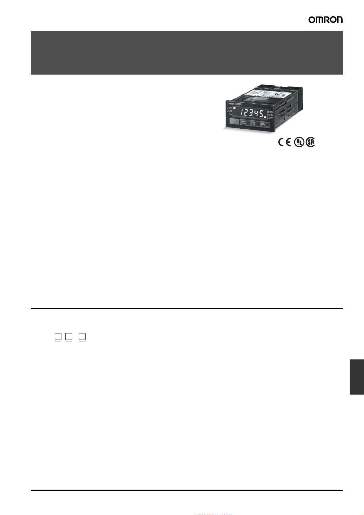
1/32 DIN Digital Panel Meter
K3GN
Compact and Intelligent Digital Panel Meter
• A single Panel Meter covering a wide range of applications.
3 main applicable functions:
• Process meter (DC voltage/current input).
• RPM processor/tachometer (frequency input).
• Digital data display for PC/PLC (RS-485 communications).
• Easy configuration
• Multi-range analog input: applicable for all standard analog
signals.
6 input ranges available: 4 to 20 mA/0 to 20 mA, 1 to 5 VDC/
0 to 5 VDC, ±5 VDC, ±10 VDC.
• 5 KHz max. input-pulse frequency range.
• Scaling in a wide range of engineering units.
• Programmable output operation action, decimal point
position setting, teaching function for input range, leading
zero suppression, average processing.
• Advanced and compact design
• Very compact 1/32 DIN housing: 48 (W) x 24 (H) x 83 (D).
• 5-digit display with programmable display color in red or
green.
• Good visibility: High contrast backlit LCD display.
• High protection against water and dust: NEMA4X/IP66 front
panel.
• Selectable outputs: 2 relay outputs, 3 transistor outputs,
RS-485, and combinations of these.
• High accuracy: ±0.1% full scale.
• Easy to configure through the front panel or via RS-485.
• EN/IEC conformity with CE marking and UL/CSA approval.
®
Model Number Structure
■ Model Number Legend
K3GN - -
12 3
1. Input Type
ND: DC voltage/current, NPN
PD: DC voltage/current, PNP
2. Output Type
C: 2 relay contact outputs (SPST-NO)
T1: 3 transistor outputs (NPN open collector)
T2: 3 transistor outputs (PNP open collector)
3. Communications Output Type
None: Communications not supported
FLK: RS-485
24 VDC
Panel
indicators
1/32 DIN Digital Panel Meter K3GN K-7
Ordering Information
■ List of Models
Input type Supply
DC voltage/current, NPN 24 VDC Dual relays (SPST-NO) K3GN-NDC 24 VDC K3GN-NDC-FLK 24 VDC
DC voltage/current, PNP Dual relays (SPST-NO) K3GN-PDC 24 VDC K3GN-PDC-FLK 24 VDC
voltage
Three NPN open collector K3GN-NDT1 24 VDC K3GN-NDT1-FLK 24 VDC
Three PNP open collector K3GN-PDT2 24 VDC K3GN-PDT2-FLK 24 VDC
Output Communications
No communications RS-485
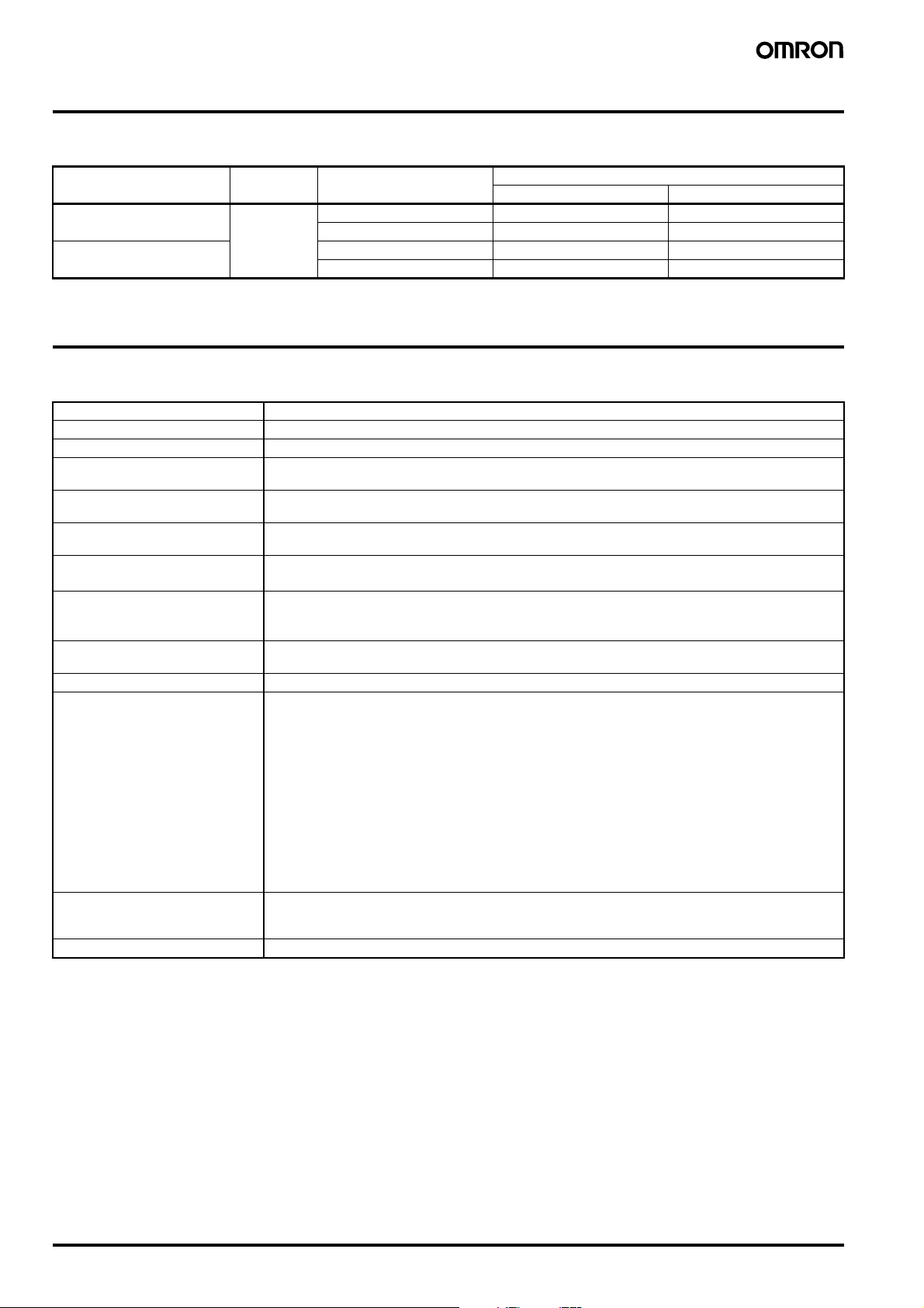
Specifications
■ Ratings
Supply voltage 24 VDC
Operating voltage range 85% to 110% of the rated supply voltage
Power consumption (see note) 2.5 W max. (at max. DC load with all indicators lit)
Insulation resistance 20 MΩ min. (at 500 VDC) between external terminal and case.
Dielectric strength 1,000 VAC for 1 min between external terminal and case.
Noise immunity ±480 V on power supply terminals in normal mode, ±1,500 V in common mode, ±1 µs, or 100 ns for square-
Vibration resistance
Shock resistance
Ambient temperature Operating: −10°C to 55°C (with no condensation or icing)
Ambient humidity Operating: 25% to 85% (with no condensation)
EMC (EMI) EN61326+A1 Industry
Approved standards UL508, CSA22.2;
Weight Approx. 100 g
Note: A control power supply capacity greater than the rated capacity is required when the Digital Panel Meter is turned ON. Do not forget to take
this into consideration when using several Digital Panel Meters. When power is supplied, all indicators will light and outputs will be OFF.
When using startup compensation time operation, the display will read “00000” and all outputs will be OFF.
Insulation provided between inputs, outputs, and power supply.
Insulation provided between inputs, outputs, and power supply.
wave noise with 1 ns
Malfunction: 10 to 55 Hz, 10 min each in X, Y, and Z directions; acceleration: 9.8 m/s
Destruction: 10 to 55 Hz, 30 min each in X, Y, and Z directions; acceleration: 19.6 m/s
Malfunction: Models with transistor outputs: 196 m/s
Destruction: 294 m/s
Storage: −25°C to 65°C (with no condensation or icing)
Emission Enclosure: CISPR 11 Group 1 class A: CISRP16-1/-2
Emission AC Mains: CISPR 11 Group 1 class A: CISRP16-1/-2
(EMS) EN61326+A1 Industry
Immunity ESD: EN61000-4-2: 4 kV contact discharge (level 2)
Immunity RF-interference: EN61000-4-3: 10 V/m (amplitude-modulated,
Immunity Fast Transient Noise: EN61000-4-4: 2 kV (power line) (level 3)
Immunity Burst Noise: 1 kV line to line (I/O signal line)
Immunity Surge: EN61000-4-5: 1 kV line to line
Immunity Conducted Disturbance EN61000-4-6: 3 V (0.15 to 80 MHz) (level 2)
Immunity Voltage Dip/Interrupting EN61000-4-11: 0.5 cycles, 0, 180°, 100% (rated voltage)
Conforms to EN61326+A1, EN61010-1 (IEC61010-1)
Conforms to VDE0106/P100 (finger protection) when the terminal cover is mounted.
Models with relay contact outputs: 98 m/s
2
for 3 times each in X, Y, and Z directions
2
for 3 times each in X, Y, and Z directions
2
for 3 times each in X, Y, and Z directions
8 kV air discharge (level 3)
80 MHz to 1 GHz) (level 3)
2 kV line to ground (power line)
2
2
K-8 1/32 DIN Digital Panel Meter K3GN
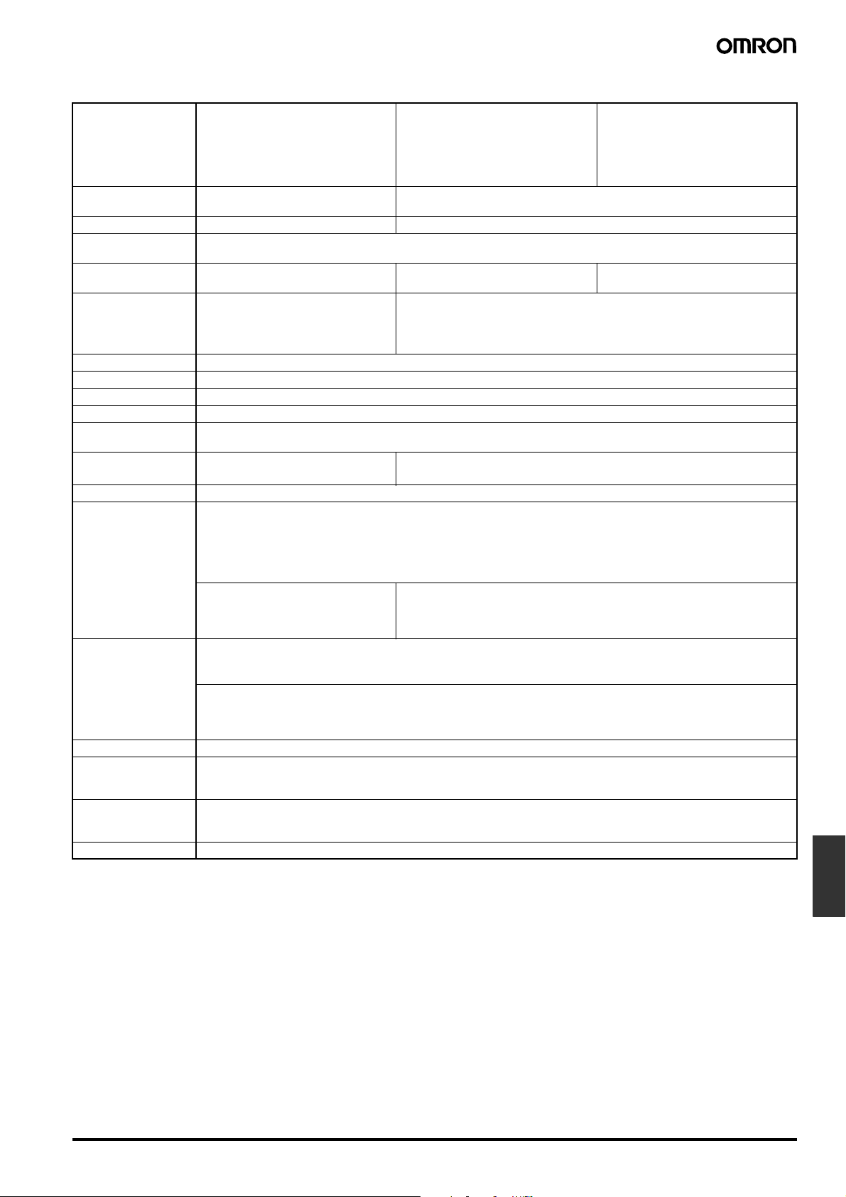
■ Characteristics
Input signal Process voltage
A/D conversion Double integral method
Sampling period 250 ms ---
Display refresh
period
Pulse measurement
method
Connectable Sensors --- ON residual voltage: 2.5 V max.
Max. displayed digits 5 digits (−19999 to 99999)
Display 7-segment digital display, character height: 7.0 mm
Polarity display “−” is displayed automatically with a negative input signal.
Zero display Leading zeros are not displayed.
Scaling function Programmable with front-panel key inputs (range of display: −19999 to 99999). The decimal point position can be set as
External controls
(see note 1)
Hysteresis setting Programmable with front-panel key inputs (0001 to 9999).
Other functions Programmable Color Display
Output Relays: 2 SPST-NO
Communications Communications function: RS-485
Delay in comparative
outputs
(transistor outputs)
Degree of protection Front panel:NEMA4X for indoor use (equivalent to IP66)
Memory protection Non-volatile memory (EEPROM) (possible to rewrite 100,000 times)
Note 1. The minimum input time for control signals is 80 ms.
2. Refer to N102 Operation Manual for more details.
(1 to 5 V, 0 to 5 V, ±5V, ±10 V)
Process current
(4 to 20 mA, 0 to 20 mA)
14 bit resolution
Sampling period (sampling times multiplied by number of averaging times if average processing is selected.)
--- Periodic measurement ---
desired.
HOLD: (Measurement value held)
ZERO: (Forced-zero)
Selectable output operating action
Teaching set values
Average processing (simple average)
Lockout configuration
Communications writing control (communications output models only)
Forced-zero set with front panel keys
Control inputs (HOLD/ZERO) selection
via front panel keys
Field calibration
Transistors: 3 NPN open collector
3 PNP open collector
Combinations:
Communications output (RS-485) + relay outputs (2 SPST-NO);
Communications output (RS-485) + transistor outputs (3 NPN open collector);
Communications output (RS-485) + transistor outputs (3 PNP open collector)
750 ms max.
Rear case: IEC standard IP20
Terminals: IEC standard IP20
No-voltage contact
(30 Hz max. with ON/OFF pulse width
of 16 ms min.)
Open collector
(5 kHz max. with ON/OFF pulse width
of 90 µs min.)
---
OFF leakage current: 0.1 mA max.
Load current: Must have a switching capacity of 15 mA min.
Must be able to reliably switch load currents of 5 mA max.
---
Startup compensation time (0.00 to 99.9 s)
Auto-zero time (0.0 to 19.9 s)
Digital data display (by RS-485
communication)
Panel
indicators
1/32 DIN Digital Panel Meter K3GN K-9
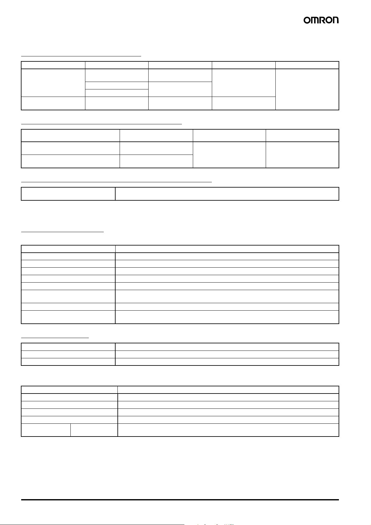
■ Measuring Ranges
Process Voltage/Current Inputs
Input Measuring range Measuring accuracy Input impedance Displayable range
DC voltage 1.000 to 5.000 V/
0.000 to 5.000 V
−5.000 to 5.000 V ±0.1% FS ±1 digit max.
−10.00 to 10.00 V
DC current 4.00 to 20.00 mA/
0.00 to 20.00 mA
No-voltage Contact/Open Collector Inputs
±0.1% FS ±1 digit max.
(at 23±3°C)
(at 23±5°C)
±0.1% FS ±1 digit max.
(at 23±3°C)
1 MΩ min. −19999 to 99999
(with scaling function)
60 Ω
Input Measuring range Measuring accuracy
No-voltage contact (30 Hz max.) with ON/
OFF pulse width of 16 ms min.
Open collector (5 kHz max.) with ON/OFF
pulse width of 90µs min.
0.05 to 30.00 HZ ±0.1% FS ±1 digit max. −19999 to 99999
0 to 5000 HZ
(at 23±5°C)
Digital Data Display (By RS-485 Communications)
Displayable range −19999 to 99999
■ Input/Output Ratings
Relay Contact Output
(Incorporating G6K Relays)
Item Resistive load (cosφ = 1)
Rated load 1 A at 30 VDC
Rated carry current 1 A max. (at COM terminal)
Max. contact voltage 60 VDC
Max. contact current 1 A (at COM terminal)
Max. switching capacity 30 VA
Min. permissible load
(P level, reference value)
Mechanical life 50,000,000 times min. (at a switching frequency of 36,000 times/hr)
Electrical life
(at an ambient temperature of 23°C)
10 mV, 10 µA
100,000 times min. (at the rated load with a switching frequency of 1,800 times/hr)
Displayable range
(with scaling function)
Transistor Output
Rated load voltage 24 VDC
Max. load current 50 mA
Leakage current 100 µA max.
■ Communications Specifications
Item RS-485
Transmission method 2-wire, half-duplex
Synchronization method Start-stop synchronization
Baud rate 1,200/2,400/4,800/9,600/19,200 bps
Transmission code ASCII
Communications Reading/Writing to
the K3GN
Refer to N102 Operation Manual for more details.
K-10 1/32 DIN Digital Panel Meter K3GN
Read/write set values, read/write scaling values, enable/disable the writing of data through communications, forced-zero control, and other data.
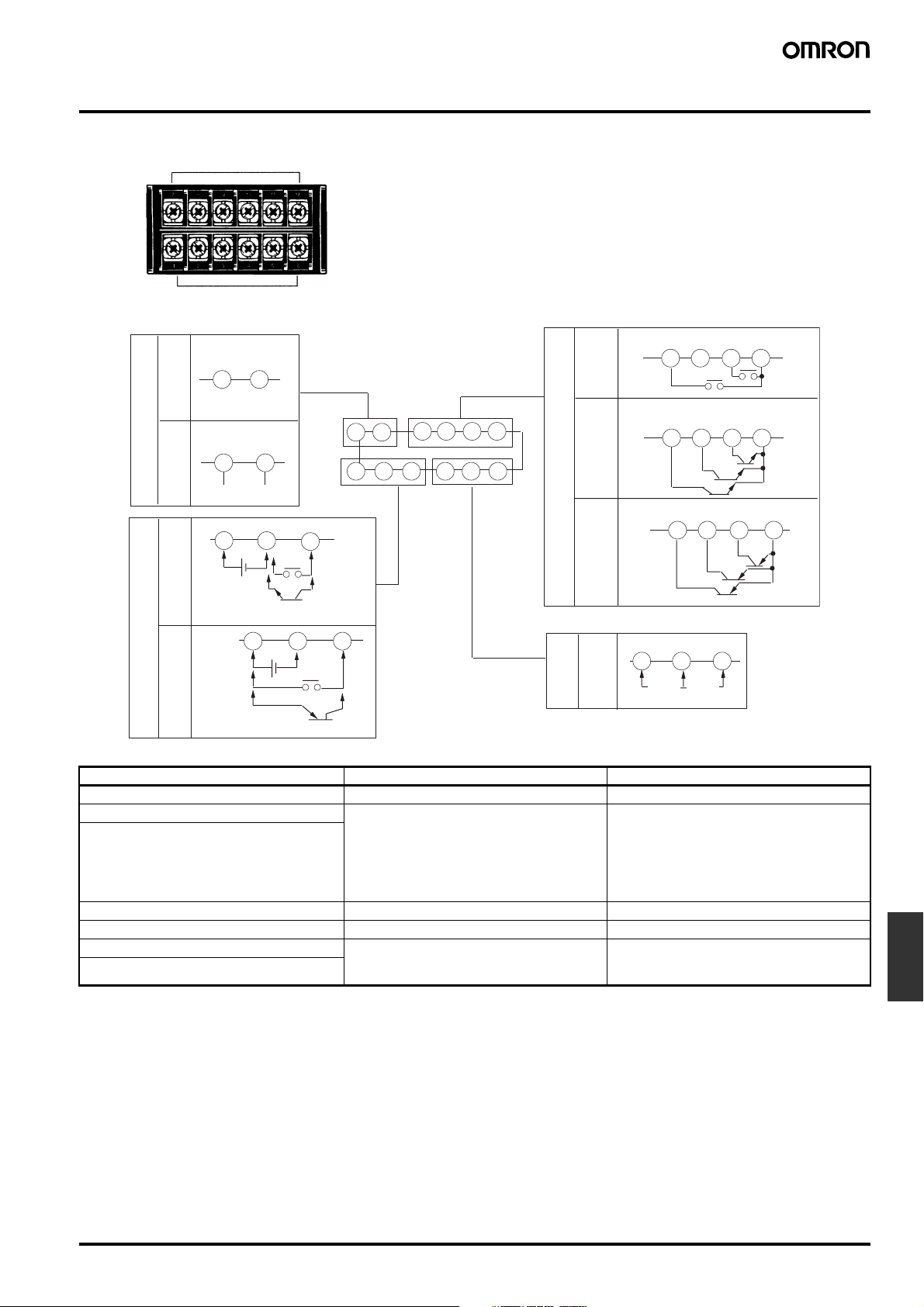
Connections
■ Terminal Arrangement
Output terminals
Input terminals
NC NC
78
Models without
communications
C
RS-485
Models with
communications
7
B (+) A (−)
8
12
Operation
power supply
24 VDC*
Models with NPN inputsModels with PNP inputs
A
Note: *Operation power supply 24VDC: Recommended DC power supply: eg. OMRON s8VS
Terminal No. Name Description
A-B Operation power Connect the operation power supply.
C-B Event input or pulse/contact input Operates as follows depending on parameter
C-A
D,F-E Analog input Connect the voltage or current analog input.
G-H Communications RS-485 communications terminals.
I,K-L Outputs Outputs relay or transistor outputs. There is
I,J,K-L
Event or pulse/contact input
Operation
power supply
24 VDC*
1
Event or pulse/contact input
C
D
78 9101112
123 456
AB
3
3
2
D
B
Models with
relay outputs
Models with
NPN transistor outputs
Models with
PNP transistor outputs
Analog input
setting:
• Holds process value.
• Calibrate the process value to zero and clear
• Pulse or contact input.
also a PASS output for models with transistor
outputs.
OUT1
9101112
OUT1
9101112
OUT1 PASS OUT2 COM
456
Voltage Current
Analog input
the forced-zero function.
OUT2
COM
PASSNCOUT2
COM
9101112
COM
Panel
indicators
1/32 DIN Digital Panel Meter K3GN K-11
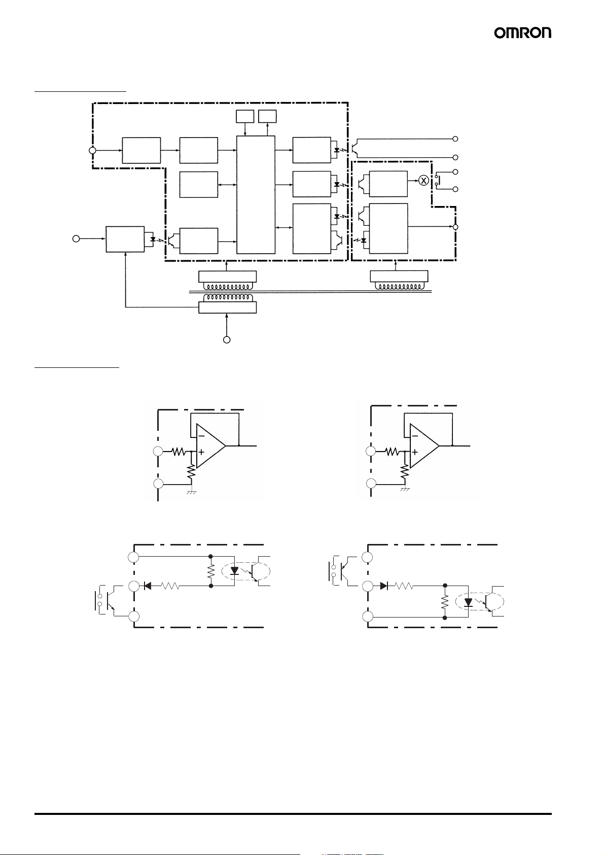
■ Wiring
Block Diagram
Analog input
terminal
Input circuit
A/D
conversion
circuit
DisplayKey
Transistor output
(See note 1.)
Drive circuit
EEPROM
Pulse/
Control
input
terminal
Control input
circuit
Operating power supply
Wavefo rm
rectification
circuit
Constant voltage circuit 1
Power supply circuit
Input Circuits
Analog Input (DC Voltage/Current)
Voltage input
A
4
Microcomputer
Drive circuit
Drive circuit
Note: 1. Transistor output models only.
2. Relay output models only.
3. Models with communications functions only.
Current input
Output
circuit
Communications driver
Constant voltage circuit 2
6
Contact output
(See note 2.)
Communications terminal
(See note 3.)
To A / DTo A/D
COM
5
B
A+B=1 MΩ
Pulse Input/Control Event Input (HOLD/ZERO)
NPN Input
24 VDC +
Hold/Zero Pulse
24 VDC
1
Ω
4.7 k
Ω
2.35 k
3
2
−
COM
PNP Input
24 VDC +
Hold/Zero Pulse
24 VDC
5
60 Ω
1
Ω
2.35 k
3
Ω
4.7 k
2
−
K-12 1/32 DIN Digital Panel Meter K3GN
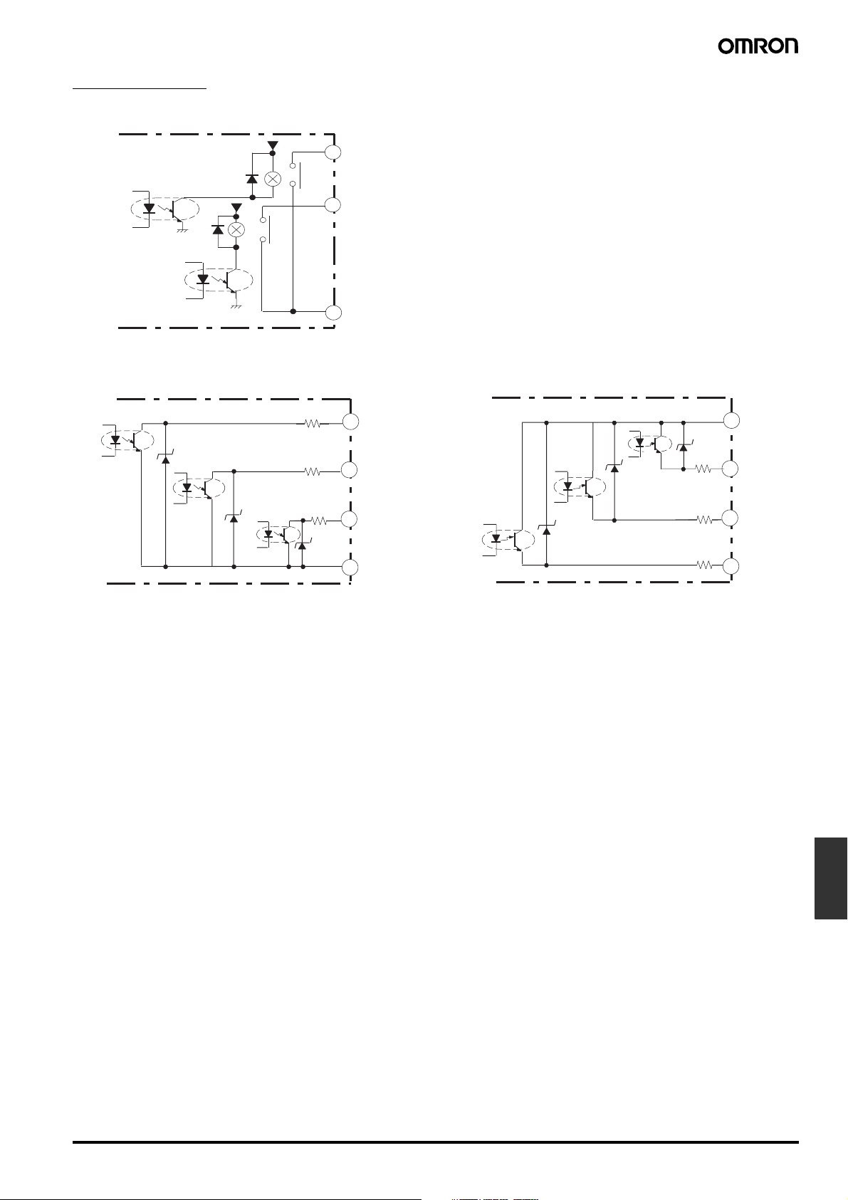
Output Circuits
Contact Output
5 V
OUT1
9
Transistor Output
NPN Output
5 V
8.2
8.2
8.2
OUT2
11
12
OUT3
PNP Output
Ω
Ω
OUT1
9
PA SS
10
Ω
OUT2
11
12
COM
8.2
8.2
8.2
12
COM
Ω
OUT2
11
Ω
PA SS
10
Ω
OUT1
9
1/32 DIN Digital Panel Meter K3GN K-13
Panel
indicators
 Loading...