

Page 1

Motor Contactor
J7KN
Main contactor
• AC & DC operated
• Integrated auxiliary contacts
• Screw fixing and snap fitting (35 mm DIN rail) up to 37 kW
• Range from 4 to 110 kW (AC 3, 380/415V)
• Finger proof (BGV A2)
• System contactors for Fuseless Load Feeders with integrated
link module
Accessories
• front mounted single pole additional auxiliary contacts
(1 NO or 1 NC)
• Side mounted additional auxiliary contacts (1 NO/1 NC)
• Mechanical interlock
• Suppressors (RC and varistor)
• Pneumatic timer modules
• Link modules MPCB - Motor contactor
Approved Standards
Standard Guide No (US,C)
UL NLDX, NLDX7
IEC 947-4-1 see page 95
VDE 0660
EN 60947-4-1
Motor Contactor J7KN 25
Page 2
Ordering Information
■ Model Number Legend
1. Motor Contactors
J7KN#-###-##-####
1324
1) Motor Contactor
2) G: DC solenoid motor contactor
3) Rated Motor Current (AC3 400V)
10: 10A
14: 14A
18: 18A
22: 22A
24: 24A
32: 32A
40: 40A
50: 50A
62: 62A
74: 74A
85: 85A
110: 110A
151: 150A
176: 175A
200: 200A
4) Integrated auxiliary contact
10: 1NO 0NC
01: 0NO 1NC
21: 2NO 1NC
22: 2NO 2NC
5) Coil voltage (AC operated)
24: AC24V 50/60Hz
48: AC48V 50Hz
90: AC100V 50/60 Hz
110: AC110V 50Hz, AC110-120V 60Hz
180: AC180-210V 50Hz, AC200-240V 60Hz
230: AC220-240V 50Hz, AC240V 60Hz
400: AC380-415V 50Hz, AC415-440V 60Hz
500: AC500-550V 50Hz, AC550-600V 60Hz
Coil voltage(DC operated)
24D: DC24V
48D: DC48V
110D: DC110V
125D: DC125V
Coil voltage(DC solenoid operated - G-type)
24D: DC24V
48D: DC48V
60D: DC60V
110D: DC110V
125D: DC125V
220D: DC220V
Coil voltage(AC & DC operated) for J7KN 151 & J7KN 176 only
24: 24V 50/60Hz, 24VDC
48: 48V 50/60Hz, 48VDC
110: 110-120V 50/60Hz, 110VDC
230: 220-240V 50/60Hz, 220VDC
400: 380-415V 50/60Hz
5
: 0NO 0NC
4: 4 main poles
2. Sytem Contactors for Fuseless Load Feeders with integrated
Link Module
J7KN-###-##-###-VK3
123
1) Additional reference for LVSG
2) Rated Motor Current (AC 3 400 V)
3) Integrated Auxiliary Contact
4) Coil voltage (AC operated)
5) Attached link module VK 3
3. Aux. Contact Modules for Motor Contactors
J73KN-#-##-#
123
1) Auxiliary Contact Modules
2) B: for motor contactor (4-37kW)
3) Combination of NO/NC contacts
4) S: side mounting for motor contactor (11-37kW and
4. Accessories for Motor Contactors
(Pneumatic Timers)
J74KN-#-## ### ##
123
1) Accessories for Motor Contactors
2) B: Motor Contactor (4-18.5kW)
3) TP: Pneumatic Timer
4) 40: 40 sec
5) DA: ON-delayed
5. Accessories for Motor Contactors (Mechanical Interlock)
J74KN-#-##
123
1) Accessories for Motor Contactors
2) B: Motor Contactor (4-18.5kW)
3) ML: Mechanical Interlock
45
10: 10 A
14: 14 A
18: 18 A
22: 22 A
10: 1NO 0NC
01: 0NO 1NC
24: AC24V 50/60Hz
48: AC48V 50Hz
110: AC110V 50Hz, AC110-120V 60Hz
180: AC180-210V 50Hz, AC200-240V 60Hz
230: AC220-240V 50Hz, AC240V 60Hz
400: AC380-415V 50Hz, AC415-440V 60Hz
500: AC500-550V 50Hz, AC550-600V 60Hz
4
C: for motor contactor (11-37kW)
D: for motor contactor (75-90kW)
E: for motor contactor (110kW)
10: 1NO 0NC
01: 0NO 1NC
11: 1NO 1NC
22: 2NO 2NC
75-90 kW)
: front mounting for motor contactor (4-37kW)
A: 6A version
F: front mounting for motor contactor (75-90kW)
U: EM and LB version
45
180: 180 sec
IA: OFF-delayed
C: Motor Contactor (11-37kW)
D: Motor Contactor (45-55kW)
E: Motor Contactor (75-90kW)
26 Motor Contactor J7KN
Page 3

6. Accessories for Motor Contactors (RC Suppressor units)
J74KN-#-## ###
123
1) Accessories for Motor Contactors
2) A: for Mini Motor Contactor and Motor Contactor
3) RC: RC-surge suppressors
4) 48: 24 - 48 VAC/DC (A+B type)
7. Accessories for Motor Contactors (4-37 kW) (Varistor units)
J74KN-#-## ###
123
1) Accessories for Motor Contactors
2) A: for Motor Contactor (4-11kW) to snap on
3) VG: Varistor Suppressors
4) 230: 110-230VAC/DC
8. Accessories for Motor Contactors
(Additional Terminals and Terminal Covers)
J7KN-#######
12
1) Accessories for Motor Contactors
2) LG-9030: for Motor Contactors (22-37 kW)
LG-11224: for Motor Contactors (75-90 kW)
LG-10404: for Motor Contactors (75-90 kW)
Marking Systems for contactors J7KNA - J7KN 74 and aux.
contact blocks J73KN-B
9. Insulated wiring systems for motor contactors
Parallel or reverse contactors
Star-Delta contactors
J75-WK-##
1 2 3
1) Additional reference for LVSG
2) Wiring system
3) Combination of 2 contactors, type:
21 = J7KN 10 - ..22
41 = J7KN 24 - ..40
4
(4-18.5kW)
(between DIN-rail and Contactor)
B: for Mini Motor Contactor and Motor Contactor
(4-55kW)
C: for Motor Contactor (4-37kW) to snap on the contactor
D: for Mini Motor Contactor (4-5.5kW)
230: 110 - 230 VAC/DC (A+B type)
400: 250 - 415 VAC/DC (A+B type)
24: 12 - 48 VAC/DC (C+D type)
110: 48 - 127 VAC/DC (C+D type)
230: 110 - 250 VAC/DC (C+D type)
4
to coil terminals
B: for Motor Contactor (4-37kW) to snap on to contactor
400: 250-415VAC/DC
Additional Terminal for Single Pole
Additional Terminal for Single Pole
Terminal Cover for 3 terminals
P487-1: Marking plate, 2-section without marking, divisible
P245-1: Marking plate, 4-section without marking, divisible
Star - delta combination of 3 contactors, type:
22 = J7KN 10 - ..22
Motor Contactor J7KN 27
Page 4
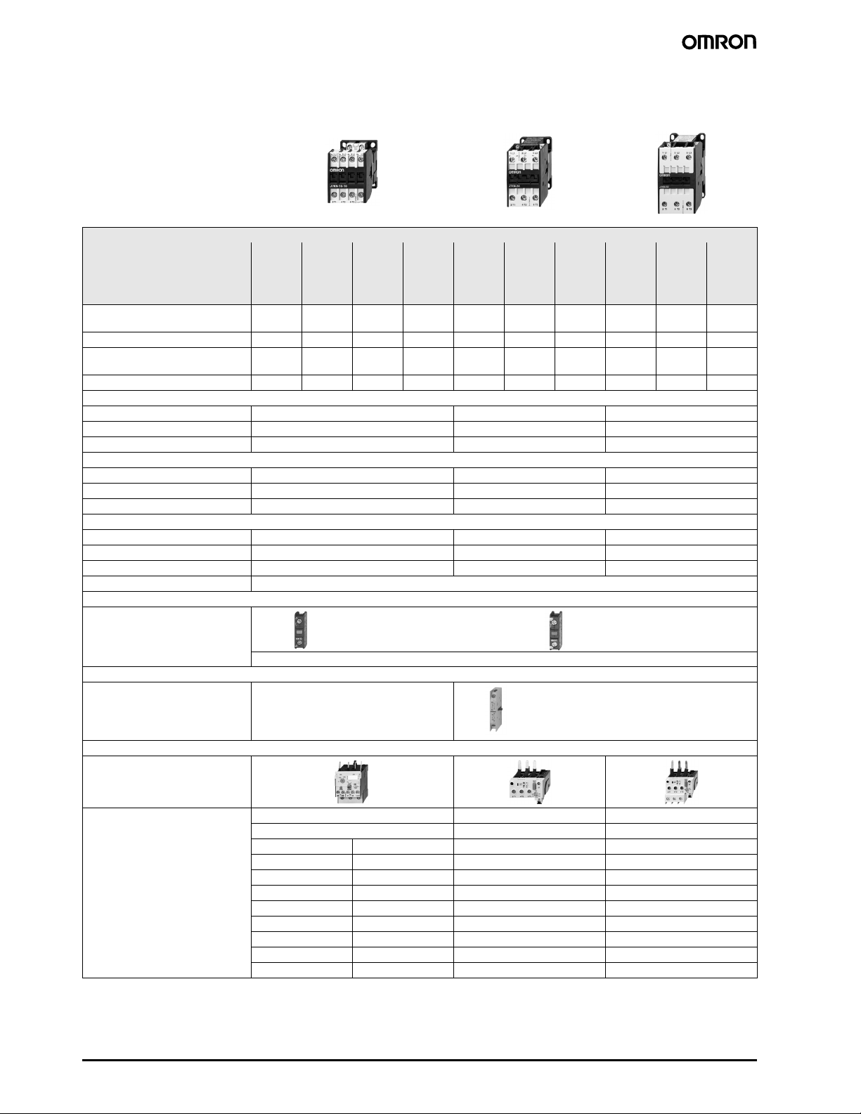
■ List of Models
Contactors 3-pole
• Up to 210A AC3
• Up to 350A AC1
• DIN-rail mounting up to AC3 74A
• International Approvals
• Data according to IEC 947 /
EN 60947
Ratings
AC3 400V Motor 10A 14A 18A 22A 24A 32A 40A 50A 62A 74A
380-400V 4kW 5,5kW 7,5kW 11kW 11kW 15kW 18,5kW 22kW 30kW 37kW
660-690V 5,5kW 7,5kW 10kW 10kW 15kW 18,5kW 18,5kW 30kW 37kW 45kW
AC1 690V at 40°C 25A 25A 32A 32A 50A 65A 80A 110A 120A 130A
Type J7KN-
Auxiliary contacts 1NO 1NO 1NO 1NO - - - - - -
Type J7KN-
Auxiliary contacts 1NC 1NC 1NC 1NC - - - - - -
Cable cross-section
Solid mm
Flexible mm
Cables per clamp 2 1 + 1 1 + 1
Auxiliary contact
I
th
AC15 230V A 12 - -
Power consumption of coils
Mounting 35mm DIN-rail or base
Additional aux. contact blocks
Front mounting
contact configuration 1NO 1NC
40°C A 16 - -
400V A 4 - -
Inrush VA 33 - 45 90 - 115 140 - 165
Hold VA 7 - 10 9 - 13 13 - 18
Operation range of coils 0,85 - 1,1 0,85 - 1,1 0,85 - 1,1
10-10
10-01
2
0,75 - 6 1,5 - 25 4 - 50
2
1 - 4 2,5 - 16 10 - 35
J7KN14-10
J7KN14-01
J7KN18-10
J7KN18-01
J7KN22-10
J7KN22-01
J7KN-24 J7KN-32 J7KN-40 J7KN-50 J7KN-62 J7KN-74
------
maximal 4 J73KN-B..
Additional aux. contact blocks
Side mounting contact configuration 1NO+1NC
Overload Relay (thermal)
Single phase protection
Temperature compensation
Trip and alarm contacts
Type J7TKN-B J7TKN-C J7TKN-D
Setting Ranges Setting Ranges Setting Ranges
0,12 - 0,18A 4 - 6A 28 - 42A 40 - 52A
0,18 - 0,27A 6 - 9A 52 - 65A
0,27 - 0,4A 8 - 11A 60 - 74A
0,4 - 0,6A 10 - 14A
0,6 - 0,9A 13 - 18A
0,8 - 1,2A 17 - 24A
1,2 - 1,8A 23 - 32A
1,8 - 2,7A
2,7 - 4A
28 Motor Contactor J7KN
Page 5
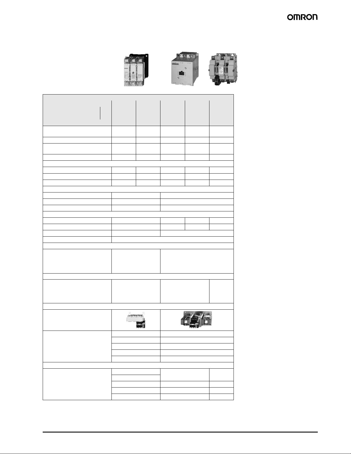
Ratings
AC3 400V Motor 85A 110A 150A 175A 210A
380-400V 45kW 55kW 75kW 90kW 110kW
660-690V 55kW 55kW 75kW 110kW 132kW
AC1 690V at 40°C 150A 170A 230A 250A 350A
Type J7KN-
Auxiliary contacts 2NO+2NC 2NO+2NC - - 2NO+1NC
Type -----
Auxiliary contacts -----
Cable cross-section
Solid mm
Flexible mm
Cables per clamp 11111
Auxiliary contact
I
th
AC15 230V A 12 3
Power consumption of coils
Mounting base
Additional aux. contact blocks
Front mounting - 2NO + 2NC
contact configuration
40°C A 16 10
400V A 6 2
Inrush VA 350 - 420 350 350 700
Operation range of coils 0,85 - 1,1 0,85 - 1,1
85-22
2
10 - 70 10 - 70 busbar busbar busbar
2
16 - 50 16 - 50 18x4 18x4 22x4
hold VA 23 - 29 5 5 20
J7KN110-22
J7KN-151 J7KN-176 J7KN-200-
21
Additional aux. contact blocks
Side mounting - 1NO + 1NC contact configuration
Overload Relay (thermal)
Single phase protection
Temperature compensation
Trip and alarm contacts
Type J7TKN-E J7TKN-F
Setting Ranges Setting Ranges
60 - 90A 100 - 150A
80 - 120A 140 - 220A
Busbar Sets
J74TK-SU-176 J74TK-SU-
200
Motor Contactor J7KN 29
Page 6
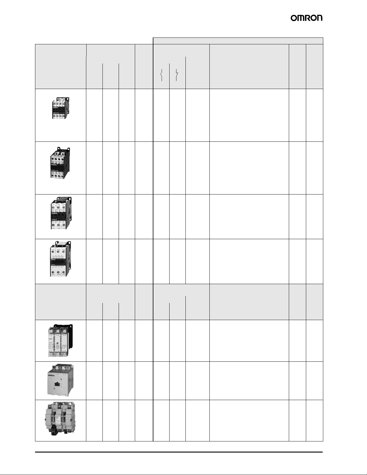
Contactors 3-pole
AC Operated
Ratings Rated
Aux. Contacts Type Pack Weight
Current
AC2, AC3 AC1 Built-in Additional
380V
500VkW660V
400V
690V
690V
see
page 33
415V
kW
4
4
5.5
5.5
7.5
7.5
11
11
4
4
5.5
5.5
7.5
7.5
11
11
11
15
18.5
5.5
5.5
7.5
7.5
10
10
10
10
5.5
5.5
7.5
7.5
10
10
10
10
15
18.5
18.5
kW
5.5
5.5
7.5
7.5
10
10
10
10
5.5
5.5
7.5
7.5
10
10
10
10
15
18
18.5
A
25
25
25
25
32
32
32
32
25
25
25
25
32
32
32
32
50
.5
65
80
NO NC
1
1
1
1
-
Ty p e
max. 4
J73KN-B
1
-
1
-
1
-
1
--- - --
-
-
max. 4
-
-
J73KN-B +
2 J73KNC-11S
.
Coil Voltage
*1
24 24V 50/60Hz
110 110V 50Hz
230 220-240V 50Hz
J7KN-10-10###
J7KN-10-01###
J7KN-14-10###
J7KN-14-01###
J7KN-18-10###
J7KN-18-01###
J7KN-22-10###
J7KN-22-01###
J7KN-24###
J7KN-32###
J7KN-40###
pcs.
1
1
1
1
1
1
1
1
1
1
1
kg/pc.
0.23
0.23
0.23
0.23
0.23
0.23
0.23
0.23
0.48
0.48
0.48
22
30
30
110
30
37
37
120
37
45
45
130
Ratings Rated
-
-
max. 4
-
-
J73KN-B +
2 J73KNC11S
-
-
J7KN-50###
J7KN-62###
J7KN-74###
Aux. Contacts Type Pack Weight
Current
AC2, AC3 AC1 Built-in
380V
500VkW660V
415V
kW
455555755555150
759075907590230
690V
kW
690V
A
17022
250--
NO NC
2
2
-
-
max. 3
1 x J73KND22F or
230 220-230V 50Hz
Coil Voltage
400 380-400V 50Hz
J7KN-85-22###
J7KN-110-22###
J7KN-151###
J7KN-176###
*2
*2
1 x J73KND11F and
2 x J73KND11S
110 132 132 350 2 1 J73KN-E-22J7KN-200-21###
1
0.85
1
0.85
1
0.85
*1
pcs. kg/pc.
1
1.8
1
1.9
1
4
1
4
*2
17.3
*1
Coil voltage range and other coil voltages see page 36
*2
AC and DC in one coil
30 Motor Contactor J7KN
Page 7
DC Operated
Aux. Contacts
see page 33
Built-in Additional 24
NO NC Ty p e pcs kg/pc. Ty pe Ty p e
max. 3
-
1
1
1
1
-
1
1
1
1
-
-
-
-
-
-
-
1
1
1
1
1
1
1
1
-
-
-
-
-
-
J73KN-B
max. 4
J73KN-B
max
. 3
J73KN-B
+
2 J73KNC-11S
Typ e Coil voltage Pack Weight Accept Overload
Relay
J7KN-10-10###D
*1
J7KN-10-01###D
J7KN-14-10###D
J7KN-14-01###D
J7KN-18-10###D
J7KN-18-01###D
J7KN-22-10###D
J7KN-22-01###D
J7KNG-10-10###D
J7KNG-10-01###D
J7KNG-14-10###D
J7KNG-14-01###D
J7KNG-18-10###D
J7KNG-18-01###D
J7KNG-22-10###D
J7KNG-22-01###D
J7KN-24###D
*1
J7KNG-24###D
J7KN-32###D
J7KNG-32###D
J7KN-40###D
J7KNG-40###D
48
60
110
125
220
24V DC
48V DC
60V DC
110V DC
125V DC
220V DC
1
1
1
1
1
1
1
1
1
1
1
1
1
1
1
1
1
1
1
1
1
1
page 56 page 57
J7TKN-B -
0.25
0.25
0.25
0.25
0.25
0.25
0.25
0.25
J7TKN-B -
0.53
0.53
0.53
0.53
0.53
0.53
0.53
0.53
0.55
J7TKN-B
J7TKN-C
0.57
0.55
0.57
0.55
0.57
Busbar Set for
Overload Relay
-
-
-
-
-
-
-
-
-
-
-
-
-
-
-
-
-
-
-
-
Wiring Diagram
Coil Circuits see page 35
Terminal Markings
-10
-01
-10
-01
-
-
max. 3
-
-
J73KN-B
+
2 J73KN-
-
-
J7KN-50###D
*1
J7KN-62###D
J7KN-74###D
1
0.9
J7TKN-D
1
0.9
1
0.9
C-11S
Aux. Contacts Typ e Coil voltage Weight Accept Overload
Relay
Busbar Set for
Overload Relay
Built-in page 56 page 57
110
NO NC
2211-
-
--max. 3
1 x J73KND22 or
J7KN-85-21###D
J7KN-110-21###D
J7KN-151-###
J7KN-176-###
*2
*2
220
110V DC
220V DC
kg/pc. Ty p e Ty pe
1
1.8
J7TKN-E -21/-22
1
1.9
1
4
J7TKN-F
1
4
J7TKN-F
J73TK-SU-176
1 x J73KND11 and
2 x J73KND11S
21 J7KN-200-21###
*2
1 7.3 J7TKN-F J73TK-SU-200 -21
*1
Only 3 additional Aux. Contacts are possible! (See also the wiring diagrammms coil circuit DC operated page 35)
*2
AC and DC in one coil
Motor Contactor J7KN 31
Page 8

System Contactors for Fuseless Load Feeders with integrated Link Module (see page 72)
AC Operated
Ratings Rated
AC2, AC3 AC1 Built-in Additional
380V
500VkW660V
400V
415V
kW
4
5.5
7.5
11
*1
Coil voltage range and other coil voltages see page 36
5.5
7.5
10
10
690V
kW
5.5
7.5
10
10
Contactors 4-pole
AC Operated
Ratings Rated
AC2,
AC3
380V
400V
415V
kW
4
5.5
7.5
11
AC1 AC1
400VkW690V
17.5
17.5
22
22
Current
A
25
25
32
32
Current
690V
A
25
25
32
32
Aux. Contacts Type Pack Weight
*1
pcs. kg/pc.
1
1
1
1
*1
pcs. kg/pc.
1
1
1
1
NO NC
1
-
1
-
1
-
1
-
Aux. Contacts
see page 33
Built-in
NO NC
-
-
-
-
-
-
-
-
see
page 33
Ty p e
max. 4
J73KN-B
Additional
see
below
Ty p e
max. 4
J73KN-B
24 24V 50/60Hz
Coil Voltage
110 110V 50Hz
230 220-240V 50Hz
J7KN-10-10 ###-VK3
J7KN-14-10 ###-VK3
J7KN-18-10 ###-VK3
J7KN-22-10 ###-VK3
Typ e Pack Weight
Coil Voltage
24 24V 50/60Hz
110 110V 50Hz
230 220-240V 50Hz
J7KN-10-4 ###
J7KN-14-4 ###
J7KN-18-4 ###
J7KN-22-4 ###
0.25
0.25
0.25
0.25
0.22
0.22
0.22
0.22
75
90
*1
Coil voltage range and other coil voltages see page 36
159
173
230
250
DC Operated
Ratings Rated
AC2,
AC3
380V
400V
415V
kW
4
5.5
7.5
11
*1
Coil voltage range and other coil voltages see page 36
AC1 AC1
400VkW690V
17.5
17.5
22
22
Current
A
25
25
32
32
-
-
-
-
Aux. Contacts
see page 33
Built-in
NO NC
-
-
-
-
-
-
-
-
max. 3
J73KN-D-11F
J73KN-D-22F
J73KN-D-11S
Additional
see
below
Ty p e
max. 4
J73KN-B
J7KN-151-4 ###
J7KN-176-4 ###
Typ e Pack Weight
Coil Voltage
24 24V 50/60Hz
110 110V 50Hz
230 220-240V 50Hz
J7KNG-10-4 ###D
J7KNG-14-4 ###D
J7KNG-18-4 ###D
J7KNG-22-4 ###D
*1
1
4.7
1
4.7
pcs. kg/pc.
1
0.53
1
0.53
1
0.53
1
0.53
32 Motor Contactor J7KN
Page 9
10
10
10
10
10
10
*1
0.02
0.02
0.02
0.02
0.02
0.02
Auxiliary Contact Blocks for contactors J7KN-10... to -74... type J73KN for low level switching
Front mounting Rated Operational Current Contacts Ty p e Pack Weig ht
AC15
230V
A A A NO NC pcs. kg/pc.
3
3
3
3
6
6
AC15
400V
2
2
2
2
4
4
AC1
690V
10
10
10
10
25
25
EM LB
J73KN-B-10
-
-
-
1
J73KN-B-01
-
-
1
-
J73KN-B-10U
-
1
-
-
J73KN-B-01U
1
-
-
-
J73KN-B-10A
-
-
-
1
J73KN-B-01A
-
-
1
-
Auxiliary Contact Blocks for contactors J7KN-151... to 176... type J73KN for low level switching
Rated Operational Current Contacts Ty p e Pack Weight
AC15
230V
A A A Mounting NO NC pcs. kg/pc.
3
3
3 2 10 side 1 1 J73KN-D-11S 10.12
AC15
400V
2
2
AC1
690V
10
10
front 1
1
J73KN-D-11F
2
2
J73KN-D-22F
1
0.08
1
0.08
Auxiliary Contact Blocks
for contactors J7KN-24... to KN-74 and J7KN-200... type J73KN for low level switching
Rated Operational Current Contacts Ty p e Pack Weight
AC15
230V
A A A Mounting NO NC pcs. kg/pc.
3
3
AC15
400V
2
2
AC1
690V
10
10
max. 2 side mounting
(J7KN-24-74)
max. 2 front mounting
(J7KN-200)
1
1
J73KN-C-11S
2
2
J73KN-E-22
Pneumatic Timer for contactors J7KN-10... to -40...
Function Time range Contacts Ty pe Pack Weight
s pcs. kg/pc.
NO NC NO NC
On-delay 0.1 - 40 1 1 - - J74KN-B-TP40DA 10.09
On-delay 10 - 180 1 1 - - J74KN-B-TP180DA 10.09
Off-delay 0.1 - 40 - - 1 1 J74KN-B-TP40IA 10.09
Off-delay 10 - 180 - - 1 1 J74KN-B-TP180IA 10.09
Mechanical Interlocks
Interlocks contactor with contactor Mounting Ty pe Pack Weight
Ty p e + Ty p e pcs. kg/pc.
J7KN10 - J7KN40 + J7KN10 - J7KN40 horizontal J74KN-B-ML 1 0.006
J7KN24 - J7KN74 + J7KN24 - J7KN74 horizontal J74KN-C-ML 1 0.010
J7KN85 - J7KN110 + J7KN85 - J7KN110 horizontal J74KN-D-ML 1 0.076
J7KN151 - J7KN176 + J7KN151 - J7KN176 horizontal J74KN-E-ML 1 0.076
1010.02
0.12
1. suitable according to DIN 19240 (test ratings 17V DC, 5mA) Technical data see page 49
Motor Contactor J7KN 33
Page 10

Suppressor Units
Var isto r
snap on coil
terminals
Var isto r
snap on top of
contactor
RC-Unit
snap on
contactor
RC-Unit
snap on
contactor
RC-Unit
to fix via
fixing band or
adhesive strip
with contactor
Suitable for Contactors Suitable for Coil Voltages Ty p e Pack
J7KNA
J7KN10-J7KN22
J7KN10-J7KN74 110 - 230 V AC/DC
J7KNA 12 - 48 V AC/DC
J7KN10-J7KN74 12 - 48 V AC/DC
J7KN85-J7KN110 24 - 48 V AC/DC
110 - 230 V AC/DC
250 - 415 V AC/DC
250 - 415 V AC/DC
48 - 127 V AC/DC
110 - 230 V AC/DC
48 - 127 V AC/DC
110 - 230 V AC/DC
110- 250 V AC/DC
250 - 415 V AC/DC
J74KN-A-VG230
J74KN-A-VG400
J74KN-B-VG230
J74KN-B-VG400
J74KN-D-RC24
J74KN-D-RC110
J74KN-D-RC230
J74KN-C-RC24
J74KN-C-RC110
J74KN-C-RC230
J74KN-B-RC48
J74KN-B-RC230
J74KN-B-RC400
pcs.
10100.01
10100.02
10
10
10
10
10
10
5
5
5
Weight
kg/pc.
0.01
0.02
0.02
0.036
0.036
0.02
0.036
0.036
0.04
0.04
0.04
Additional Terminals Single Pole
For Contactors Cable Cross-sections to clamp mm² Ty pe Pack Weight
solid or
stranded
J7KN50 - KN74 4 - 35 6 - 25 4 - 25 J74KN-LG-9030 1 0.052
J7KN151 - KN176 16 - 120 --- 16 - 95 J74KN-LG-11224
flexible flex. with multi-
core cable end
Terminal Covers for terminal protection according DIN 57106, BVG-A2
For Contactors Specification Ty p e Pack Weight
J7KN151 - KN176 one unit J74KN-LG-10404 10.12
Marking Systems for contactors J7KNA to J7KN74 and aux. contact blocks J73KN-B
Description Specification Ty pe Pack Weight
Marking Plate 2-section without marking, divisible J74KN-P487-1 100 0.025
Marking Plate 4-section without marking, divisible J74KN-P245-1 100 0.050
pcs. kg/pc.
pcs. kg/pc.
pcs. kg/pc.
34 Motor Contactor J7KN
Page 11

Insulated wiring systems for motor contactors
Description Versio n
For reversing or parallel
contactors ( 2 parts )
(A)
25 J7KN 10 - 22 J75-WK-21 1
40 J7KN 24 - 40 J75-WK-41 1
For contactors Type Pack
pcs
For star-delta combination
(3 parts)
25 J7KN 10 - 22 J75-WK-22 1
■ Wiring Diagrams Coil Circuit
AC operated DC operated
J7KN-10...
to
J7KN-110...
with double winding coil*
J7KN-10...D
to
J7KN-22...D
J7KN-24...D
to
J7KN-74...D
J7KN-110...D
J7KNG
A1+
1
AC and DC operated
J7KN-151...
to
J7KN-176...
J7KN-200-21
~/
A1
A2~/
~
-
+
~
L1 L2
31
32
A2-
*1) 3 Additional Aux. Contacts are possible with the J7KN-.....D
types! (See also page 31)
Motor Contactor J7KN 35
Page 12

Specifications
■ Coil Voltages
Type-suffix for contactor types J7KN-10... to J7KN-74...
Suffix
to contactor
type e.g.
J7KN-10-10-24 for 50HzVfor 60 HzVmin Vmax Vmin Vmax
24 24 24 22 24 24 27
48 48 48 44 48 48 52
110 110 110-120 100 110 110 122
180 180-210 200-240 180 210 200 240
230 220-240 240 220 240 240 264
400 380-415 415-440 380 415 415 460
500 500-550 550-600 500 550 550 600
Standard voltages in bold type letter
Type-suffix for contactor types J7KN-85... to J7KN-110...
Suffix
to contactor
type e.g.
J7KN-85-22-24 for 50HzVfor 60 HzVmin Vmax Vmin Vmax
20 20 24 20 22 24 26
24 24 24 27 29 32
48 48 60 47 52 56 62
90 90 110-120 90 100 108 120
110 110-120 110 122 132 146
180 180-200 208-240 180 200 208 240
230 220-240 277 220 240 264 288
400 380-415 460-480 380 415 455 498
500 500-550 600-660 500 550 600 660
Standard voltages in bold type letter
Voltage Marking Rated Control Voltage U
at the coil range for
50Hz
Voltage Marking Rated Control Voltage U
at the coil range for
50Hz
60Hz
60Hz
s
V
s
V
Type-suffix for contactor types J7KN-151... to J7KN-200...
Suffix Voltage Marking Rated Control Voltage U
to contactor
type e.g.
J7KN-151-230 for 50 HzVfor 60 HzVmin Vmax Vmin Vmax Vmax
24 24 24 24 24 24 24 24
48 48 48 48 48 48 48 48
110 110 120 110 120 110 120 110
230 220-240 220-240 220 240 220 240 220
400 380-415 380-415 380 415 380 415 -
Standard voltages in bold type letter
at the coil range for
50Hz
60Hz DC
s
V
36 Motor Contactor J7KN
Page 13

■ Engineering data and characteristics
Approximate Values for three-phase Motors
Motor Full Load Currents
Approximate values of motor F.L.C. and minimum „slow blow“ respectively „gL“ short-circuit fuse
Motor rating 220-230V Motor 240V Motor 380-400V Motor 415V Motor 500V Motor 660-690V Motor
Range according to BS for 415V Value of fusing at
kW PS~hp hp cos %
0.06 0.08 - 0.7 59 0.38 1 1 0.35 1 1 0. 22 11- - -0.1611- - -
0.09 0.12 - 0.7 60 0.55 2 2 0.5 2 2 0.33 11- - -0.2411- - -
0.12 0.16 - 0.7 61 0.76 2 2 0.68 2 2 0. 42 22- - -0.3311- - -
0.18 0.24 - 0.7 61 1.1 2 2 1 2 2 0.64 22- - -0.4611- - -
0.25 0.34 - 0.7 62 1.4 4 2 1.38 4 2 0. 88 22- - -0.5922- - -
0.37 0.5 - 0.72 64 2.1 4 4 1.93 4 4 1.22 4 2 - - - 0.85 2 2 0.7 2 2
0.55 0.75 - 0.75 69 2.7 4 4 2.3 4 4 1.5 42- - -1.24 20.922
0.75 1 1 0.8 74 3.3 6 4 3.1 6 4 2 4 4 2 4 4 1.48 4 2 1.1 2 2
1.1 1.5 1.5 0.83 77 4.9 10 6 4.1 6 6 2. 6 442.5442.1441.542
1.5 2 2 0.83 78 6.2 10 10 5.6 10 10 3.5 643.5642.64 42 44
2.2 3 3 0.83 81 8.7 16 10 7.9 16 10 5 10 6 5 10 6 3.8 6 6 2.9 6 4
2.5 3.4 - 0.83 81 9.8 16 16 8.9 16 10 5.7 10 10 - - - 4.3 6 6 - - -
3 4 4 0.848111.620 1610.620 16 6.6 16 10 6.5 16 10 5.1 10 10 3.5 6 4
3.75 5 0.848214.225 2013 25 16 8.2 16 10 7.5 16 10 6.2 16 10 - - -
4 5.5 - 0.84 82 15.3 25 20 14 25 20 8.5 16 10 - - - 6.5 16 10 4.9 10 6
5.5 7.5 7.5 0.85 83 20.6 35 25 18.9 35 25 11.5 20 16 11 20 16 8.9 16 10 6.7 16 10
7.51010 0.868527.4353524.8353515.5 25 20 14 25 16 11.9 20 16 9 16 10
8 11 - 0.86 85 28.8 50 35 26.4 35 35 16.7 25 20 - - - 12.7 20 16 - - -
11 15 15 0.86 87 39.2 63 50 35.3 50 50 22 35 25 21 35 25 16.7 25 20 13 25 16
12.5 17 - 0.86 87 43.8 63 50 40.2 63 50 25 35 35 - - - 19 35 25 - - -
15 20 20 0.86 87 52.6 80 63 48.2 80 63 30 50 35 28 35 35 22.5 35 25 17.5 25 20
18.5 25 25 0. 86 88 64.9 100 80 58.7 80 63 37 63 50 35 50 50 28.5 50 35 21 35 25
20 27 - 0.86 88 69.3 100 80 63.4 80 80 40 63 50 - - - 30.6 50 35 - - -
22 30 30 0.87 89 75.2 100 80 68 100 80 44 63 50 40 63 50 33 50 50 25 35 35
25 34 - 0.87 89 84.4 125 100 77.2 100 100 50 80 63 - - - 38 63 50 - - -
30 40 40 0.87 90 101 125 125 92.7 125 100 60 80 63 55 80 63 44 63 50 33 50 35
37 50 50 0.87 90 124 160 160 114 160 125 72 100 80 66 100 80 54 80 63 42 63 50
40 54 - 0.87 90 134 160 160 123 160 160 79 100 100 - - - 60 80 63 - - -
45 60 60 0.88 91 150 200 160 136 200 160 85 125 100 80 100 100 64.5 1 00 80 49 63 63
51 70 - 0.88 91 168 200 200 154 200 200 97 125 100 - - - 73.7 100 80 - - -
55 75 - 0.88 91 181 250 200 166 200 200 10 5 160 125 - - - 79 125 100 60 80 63
59 80 80 0.88 91 194 250 250 178 250 200 112 160 125 105 160 125 85.3 125 100 - - -
75 100 100 0.88 91 245 315 250 226 315 250 140 200 160 135 200 160 106 160 125 82 125 100
90 125 125 0.88 92 292 400 315 268 315 315 170 250 200 165 200 200 128 160 160 98 125 125
110 150 150 0.88 92 358 500 400 327 400 400 205 250 250 200 250 250 156 200 200 118 160 125
129 175 175 0.88 92 420 500 500 384 500 400 242 315 250 230 315 250 184 250 200 - - -
132 180 - 0.88 92 425 500 500 393 500 500 245 315 250 - - - 186 250 200 140 200 160
147 200 200 0.88 93 472 630 630 432 630 500 273 315 315 260 315 315 207 250 250 - - -
160 220 - 0.88 93 502 630 630 471 630 630 295 400 315 - - - 220 315 250 170 200 200
184 250 250 0.88 93 590 800 630 541 630 630 340 400 400 325 400 400 259 315 315 - - -
200 270 - 0.88 93 626 800 800 589 800 630 370 500 400 - - - 278 315 315 215 250 250
220 300 300 0.88 93 700 1000 800 647 800 800 408 500 500 385 500 400 310 400 400 - - -
250 340 - 0.88 93 803 1000 1000 736 1000 800 460 630 500 - - - 353 500 400 268 315 315
257 350 350 0.88 93 826 1000 1000 756 1000 800 475 630 630 450 630 500 363 500 400 - - -
295 400 400 0.88 93 948 1250 1000 868 1000 1000 546 800 630 500 630 630 416 500 500 - - -
315 430 - 0.88 93 990 1250 1250 927 1250 1000 580 800 630 - - - 445 630 500 337 400 400
355 483 - 0.89 95 - - - - - - 636 800 800 - - - 483 630 630 366 500 400
400 545 - 0.89 96 - - - - - - 710 1000 800 - - - 538 630 630 410 500 500
The motor F.L.C. be valid for standard internal and surface cooled three-pole
motors with 1500 min
the table and D.O.L.-start: starting current max. 6x motor F.L.C., starting time
max. 5s; star-delta-start: starting current max. 2x motor F.L.C., starting time
max. 15s. For motors with higher F.L.C., higher starting current and / or longer
starting time, larger short-circuit fuses are required.
-1
. The fuses values be valid for the motor F.L.C. shown in
motor start
F. L . C .AD.O. L.AYDAF. L . C .AD.O. L.AYDAF. L . C .AD.O. L.AYDAF. L . C .AD.O.L .AYDAF. L . C .AD.O. L.AYDAF. L . C .AD.O. L.AYD
The maximum admissible value is dependent on the switchgear
respectively thermal overload relay.
Value of fusing at
motor start
Value of fusing at
motor start
Value of fusing at
motor start
Value of fusing at
motor start
Value of fusing at
motor start
A
Motor Contactor J7KN 37
Page 14

Approximate values of motor F.L.C. according to CSA and UL
Motor
rating
hp A A A A A A A A A A A A
*1
Motor F.L.C. at 110-120V Motor F.L.C. at 220-240V
1-phase 2-phase 3-phase 1-phase 2-phase 3-phase 1-phase 2-phase 3-phase 1-phase 2-phase 3-phase
½ 9.8 4.0 4.4 4.9 2.0 2.2 2.5 1.0 1.1 2.0 0.8 0.9
¾ 13.8 4.8 6.4 6.9 2.4 3.2 3.5 1.2 1.6 2.8 1.0 1.3
1 16.0 6.4 8.4 8.0 3.2 4.2 4.0 1.6 2.1 3.2 1.3 1.7
1½ 20.0 9.0 12.0 10.0 4.5 6.0 5.0 2.3 3.0 4.0 1.8 2.4
2 24.0 11.8 13.6 12.0 5.9 6.8 6.0 3.0 3.4 4.8 2.4 2.7
3 34.0 16.6 19.2 17.0 8.3 9.6 8.5 4.2 4.8 6.8 3.3 3.9
5 56.0 26.4 30.4 28.0 13.2 15.2 14.0 6.6 7.6 11.2 5.3 6.1
7½ 80.0 38.0 44.0 40.0 19.0 22.0 21.0 9.0 11.0 16.0 8.0 9.0
10 100.0 48.0 56.0 50.0 24.0 28.0 26.0 12.0 14.0 20.0 10.0 11.0
15 135.0 72.0 84.0 68.0 36.0 42.0 34.0 18.0 21.0 27.0 14.0 17.0
20 - 94.0 108.0 88.0 47.0 54.0 44.0 23.0 27.0 35.0 19.0 22.0
25 - 118.0 136.0 110.0 59.0 68.0 55.0 29.0 34.0 44.0 24.0 27.0
30 - 138.0 160.0 136.0 69.0 80.0 68.0 35.0 40.0 54.0 28.0 32.0
40 - 180.0 208.0 176.0 90.0 104.0 88.0 45.0 52.0 70.0 36.0 41.0
50 - 226.0 260.0 216.0 113.0 130.0 108.0 56.0 65.0 86.0 45.0 52.0
60 - - - - 133.0 145.0 - 67.0 77.0 - 53.0 62.0
75 - - - - 166.0 192.0 - 83.0 96.0 - 66.0 77.0
100 - - - - 218.0 248.0 - 109.0 124.0 - 87.0 99.0
125-----312.0-135.0 156.0 - 108.0 125.0
150-----360.0-156.0 180.0 - 125.0 144.0
200-----480.0-208.0 240.0 - 167.0 192.0
250-----602.0--302.0 - - 242.0
300--------361.0 - - 289.0
350--------414.0 - - 336.0
400--------477.0 - - 382.0
500--------590.0 - - 472.0
Determine the motor current for 200V and 208V by increasing the values for 220-240V at 200V about 15% and for 208V about 10%.
*1
Motor F.L.C. at 440-480V Motor F.L.C. at 550-600V
38 Motor Contactor J7KN
Page 15

Contactors
Data according to IEC 947-4-1, EN 60947-4-1, VDE 0660
Main Contacts Type J7KN-10 J7KN-14 J7KN-18 J7KN-22 J7KN-24 J7KN-3 2 J7KN-40 J7 KN-50 J7KN-62 J7 KN-74
Rated insulation voltage U
Making capacity I
Breaking capacity I
J7KN-10 to J7KN-22 cosϕ = 0,65 500V AC A 150 150 180 180 300 370 370 500 700 700
J7KN-24 to J7KN-72 cosϕ = 0,35 690V AC A 100 100 150 150 260 340 340 400 500 500
Utilization category AC1
Switching of resistive load
Rated operational current I
Rated operational power
of three-phase resistive loads
50-60Hz, cosϕ = 1
Rated operational current Ie (=I
Rated operational power
of three-phase resistive loads
50-60Hz, cosϕ = 1
Minimum cross-section of conductor
at load with I
Utilization category AC2 and AC3
Switching of three-phase motors
Rated operational current I
open and enclosed
Rated operational power
of three-phase motors
50-60Hz
Utilization category AC4
Switching of squirrel cage motors, inching
Rated operational current Ie (=Ith)
open and enclosed
(=Ith)
e
*1
V AC 690 690 690 690 690 690 690 690 690 690
i
eff
eff
at Ue = 690V AC A 200 200 200 200 400 500 500 700 900 900
400V AC A 180 180 200 200 380 400 400 600 800 800
1000V ACA---------
(=Ith) at 40°C, open A25253232506580110120130
e
220V kW 9,5 9,5 12,2 12,2 19,0 24,7 30,4 41,9 45,7 49,5
230V kW 9,9 9,9 12,7 12,7 19,9 25,9 31,8 43,8 47,7 51,7
240V kW 10,4 10,4 13,3 13,3 20,8 27,0 33,2 45,7 49,8 54,0
380V kW 16,4 16,4 21,0 21,0 32,9 42,7 52,6 72,3 78,9 85,5
400V kW 17,3 17,3 22,1 22,1 34,6 45,0 55,4 76,1 83,0 90,0
415V kW 17,9 17,9 23,0 23,0 35,9 46,7 57,4 79,0 86,2 93,3
440V kW 19,0 19,0 24,4 24,4 38,1 49,5 60,9 83,7 91,3 99,0
500V kW 21,6 21,6 27,7 27,7 43,3 56,2 69,2 95,2 103,8 112,5
660V kW 28,5 28,5 36,5 36,5 57,1 74,2 91,3 125,6 137,0 148,4
690V kW 29,8 29,8 38,2 38,2 59,7 77,6 95,5 131,3 143,2 155,2
1000VkW----------
) at 60°C, enclosedA2525323240556590100110
the
220V kW 9,5 9,5 12,2 12,2 15,2 20,9 24,7 34,3 38,1 41,9
230V kW 9,9 9,9 12,7 12,7 15,9 21,9 25,9 35,8 39,8 43,8
240V kW 10,4 10,4 13,3 13,3 16,6 22,8 27,0 37,4 41,5 45,7
380V kW 16,4 16,4 21,0 21,0 26,3 36,2 42,7 59,2 65,7 72,3
400V kW 17,3 17,3 22,1 22,1 27,7 38,1 45,0 62,3 69,2 76,1
415V kW 17,9 17,9 23,0 23,0 28,7 39,5 46,7 64,6 71,8 79,0
440V kW 19,0 19,0 24,4 24,4 30,4 41,9 49,5 68,5 76,1 83,7
500V kW 21,6 21,6 27,7 27,7 34,6 47,6 56,2 77,9 86,5 95,2
660V kW 28,5 28,5 36,5 36,5 45,7 62,8 74,2 102,8 114,2 125,6
690V kW 29,8 29,8 38,2 38,2 47,7 65,7 77,6 107,4 119,4 131,3
1000VkW----------
mm²4 4 6 6 101625355050
e
220VA121518222430405063 74
230VA11,514,518222430405062 74
240VA11141822243240506274
380-400VA10141822243240506274
415V A 9 14 18 22 23 30 40 50 62 74
440V A 9 14 18 22 23 30 40 50 62 74
500VA7 9 9 9 17,52121334242
660-690V A 6,5 8,5 8,5 8,5 17 20 20 31 40 40
1000VA--- ------
220-230V kW 3 4 5 6 6 8,5 11 12,5 18,5 22
240V kW 3 4 5 7 7 9 11,5 13,5 19 23
380-400V kW 4 5,5 7,5 11 11 15 18,5 22 30 37
415VkW4,56 8,512121620243340
440VkW4,56 8,512121620243340
500V kW 5,5 7,5 10 10 15 18,5 18,5 30 37 45
660-690V kW 5,5 7,5 10 10 15 18,5 18,5 30 37 45
1000VkW--- ------
220V A121518182430405063 63
230V A11,514,518182430405062 62
240V A11141818243240506262
380-400VA10141818243240506262
415V A 9 14 18 18 23 30 37 45 60 60
440V A 9 14 18 18 23 30 37 45 55 55
500V A 9 12 16 16 17,5 21 21 33 42 42
660V A7 9 9 9 172020314040
690V A 6,5 8,5 8,5 8,5 17 20 20 31 40 40
1000VA--- ------
Motor Contactor J7KN 39
Page 16

Utilization category AC4
Switching of squirrel cage motors, inching
Rated operational power
of three-phase motors
50-60Hz
220-230V kW 3 4 5 5 6 8,5 11 12,5 18,5 18,5
240VkW34557911,513,51919
380-400V kW 4 5,5 7,5 7,5 11 15 18,5 22 30 30
415V kW 4,5 6 8,5 8,5 12 16 20 24 33 33
440V kW 4,5 6 8,5 8,5 12 16 20 24 33 33
500V kW 5,5 7,5 10 10 15 18,5 18,5 30 37 37
660-690V kW 5,5 7,5 10 10 15 18,5 18,5 30 37 37
1000VkW--- ------
Main Contacts Type J7KN-10 J7KN-14 J7KN-18 J7KN-22 J7KN-24 J7KN-32 J7KN-40 J7KN-50 J7KN-62 J7KN-74
Utilization category AC 5a
Switching of gas discharge lamps
Rated operational current I
per pole at 220/230V
e
Fluorescent lamps,
uncompensated and serial c ompensated A 20 20 25 25 40 52 64 88 96 104
parallel compensated A 7 9 9 9 18 22 22 30 40 45
dual-connection A 22,5 22,5 28 28 45 58 72 98 108 117
Metal halide lamps*2,
uncompensated A1215191930 3948667278
parallel compensated A 7 9 9 9 18 22 22 30 40 45
Mercury-vapour lamps*3,
uncompensated A22,525282845587299108117
parallel compensated A 7 9 9 9 18 22 22 30 40 45
Mixed light lamps
Utilization category AC 5b
Switching of incandescent lamps
*4
*5
A202025254052648896104
Rated operational current Ie per pole at 220/230V A 12,5 12,5 12,5 12,5 25 31 31 43 56 56
Utilization category AC 6a
Transformer primary switching
at inrush n30303030303030303030
Rated operational current I
Rated operational power
dependent on inrush n
400V A 4,5 5,5 7,5 7,5 10,5 13,5 13,5 20 27 33
e
220-230V kVA 1,8 2,2 3 3 4,2 5,4 5,4 8 10,7 13
240V kVA 1,9 2,3 3,1 3,1 4,3 5,6 5,6 8,3 11,2 13,5
380-400V kVA 3,1 3,8 5,2 5,2 7,3 9,3 9,3 13,5 18,5 22,5
For different inrush-factors x
use the following formula:
Px=Pn*(n/x)
Utilization category AC 6b
Switching of three-phase capacitor banks
Maximum inrush current (peak value) as multiple k of the capacitor
rated current
Rated operational current I
Rated operational power
(sin 1)
415-440V kVA 3,4 4,2 5,7 5,7 8 10,2 10,2 15 20,5 25
500V kVA 3,9 4,8 6,5 6,5 9 11,5 11,5 17 23 28
660-690V kVA 5,4 6,5 9 9 12,5 16 16 24 32 39
k35252020252525252520
500V A8 1215,515,52332324560 70
e
220-230V kVAr 3 4,5 6 6 8,5 12 12 17 24 28
240V kVAr 3,5 5 6,5 6,5 9,5 13 13 18,5 25 29
380-400V kVAr 5 7,5 10 10 15 20 20 29 39 46
For different multiples x
use the following formula:
Px=Pk*(k/x)
Switching of detuned capacitors
Rated operational current I
Rated operational power 220-230V kVAr 2,9 5 7 7,5 11 14 16 20 28 33
415-440V kVAr 5,5 8 11 11 16 22 22 32 43 50
500V kVAr7 10131320262639 5058
660-690VkVAr7 101313202626405058
690V A 8 13 18 20 28 36 42 48 72 105
e
240V kVAr 3,1 5,4 7 8 11 14 17 20 28 36
380-400V kVAr 5 9 12,5 13 20 25 27,5 33,3 50 75
415-440V kVAr 5,5 9,5 13 14 22 27 30 36 53 75
1)
1)
1)
500V kVAr6 111517253036406075
660-690VkVAr8 1520223341485582100
Utilization category DC1
Switching of resistive load
Time constant L/R 1ms
Rated operational current I
e
1 pole24V A 20 25 32 32 50 65 80 110 120 130
60V A 20 25 32 32 50 65 80 110 120 130
110VA6 6 6 6 101010121212
220V A 0,8 0,8 0,8 0,8 1,4 1,4 1,4 1,4 1,4 1,4
3 poles in series 24V A 20 25 32 32 50 65 80 110 120 130
60V A 20 25 32 32 50 65 80 110 120 130
110VA20253232506580110120130
220VA16202020303535638080
40 Motor Contactor J7KN
Page 17

Utilization category DC3 and DC5
Switching of shunt motors and series motors
Time constant L/R 15ms
Rated operational current I
Maximum ambient temperature
Operation open °C -40 to +60 (+90)
with thermal overload relay open °C -25 to +60
enclosed °C -25 to +40
Storage °C -50 to +90
Short circuit protection
for contactors without thermal overload relay
Coordination-type "1" according to IEC 947-4-1
Contact welding without
hazard of persons
max. fuse size gL (gG)A63636363808080160160160
Coordination-type “2” according to IEC 947-4-1
Light contact welding accepted
max. fuse size gL (gG)A25353535505050100125125
Contact welding not accepted
max. fuse size gL (gG)A16161616253535506363
For contactors with thermal overload relay the device with
the smaller admissible backup fuse (contact or or thermal
overload relay) determines the fuse size.
Cable cross-sections
for contactors without thermal overload relay
main connector solid or stranded mm² 0,75 - 6 1,5 - 25 4 - 50
Cables per clamp 2 1 1
Cables per clamp 2 2 2
main connector solid AWG 18 - 10 16 - 10 12 - 10
Cables per clamp 2 1 1
Cables per clamp 2 2 2
Frequency of operations z
Contactors without thermal overload relay
Mechanical life
AC operated S x 10610 10 10 10 10 10 10 10 10 10
DC operated S x 10610 10 10 10 10 10 10 10 10 10
DC solenoid operated S x 10650 50 50 50 50 50 50 - - -
Short time current 10s-current A 96 120 144 176 184 240 296 360 504 592
Power loss per pole at Ie/AC3 400V W 0,21 0,35 0,5 0,75 0,7 1,3 2 2,2 3,9 5,5
Resistance to shock acc. to IEC 68-2-27
Shock time 20ms sine-wave NO g 10 10 10 10 8 8 8 8 8 8
*1
Suitable at 690V for: earthed-neutral systems, overvoltage I to IV, pollution degree 3 (standard-industry): U
Data for other conditions on request.
*2
Metal halide lamps and sodium-vapour lamps (high- and low-pressure lamps)
*3
High-pressure lamps
*4
Blended lamps, containing a mercury high-pressure unit and a tungsten helix in a flourescent glass bulb (daylight lamps)
*5
Current inrush approx. 16 x I
*6
With reduced control voltage range 0,9 up to 1,0 x Us and with reduced rated current Ie/AC1 according to Ie/AC3
Main Contacts Type J7KN-10 J7KN-14 J7KN-18 J7KN-22 J7KN-24 J7KN-3 2 J7KN-40 J7 KN-50 J7KN-62 J7 KN-74
e
flexible with multicore cable end mm² 0,75 - 4 1,5 - 16 6 - 35
1 pole24V A 20 25 32 32 50 65 80 110 120 130
60V A 6 6 6 6 30 30 30 60 60 60
110V A 1,2 1,2 1,2 1,2 1,8 1,8 1,8 1,8 1,8 1,8
3 poles in series 24V A 20 25 32 32 50 65 80 110 120 130
220V A 0,2 0,2 0,2 0,2 0,2 0,2 0,2 0,25 0,25 0,25
60V A 20 25 32 32 40 40 40 80 8 0 80
110VA20202020404040808080
220V A 2,5 2,5 2,5 2,5 4 4 4 5 5 5
*6
enclosed °C -40 to +40
flexible mm ² 1 - 4 2,5 - 16 10 - 35
solid or stranded mm² 6+(1-6) / 4+(0,75-4) 16+(2,5-6) / 10+(4-10) 50+4 / 35+6 / 25+(6-16)
flexible mm² 6+(1,5-6) / 4+(1-4) 16+(2,5-6) / 10+(4-10) 50+(4-10) / 35+(4-16)
flexible AWG 18 - 10 14 - 4 10 - 0
flexible AWG 10+( 14-10) / 12+(18-12) 4+(18-12) / 6+( 18-8) 1+(12-10) / 2+(8-12)
without load 1/h 10000 10000 10000 10000 7000 7000 7000 7000 7000 7000
AC3, Ie1/h 600 600 600 600 600 600 600 400 400 400
AC4, Ie1/h 120 120 120 120 120 120 120 120 120 120
DC3, Ie1/h 600 600 600 600 600 600 600 400 400 400
e
2,5+(0,75-2,5) / 1,5+(0,75-1,5) 6+(4-6) / 4+(2,5-4) 16+(6-16) / 10+(6-16)
2,5+(0,75-2,5) / 1,5+(0,75-1,5) 6+(4-6) / 4+(2,5-4) 25+(4-25) / 16+(4-16)
solid AWG 10+(16-10) / 12+(18-12) 10+(16 -10) / 12+(18-12) 10+(12-10) / 12+12
14+(18-14) / 16+(18-16) 1 4+(18-14) / 16+(18-16)
14+(18-14) / 16+(18-16) 8 +(18-8) / 10+(18-12) 3+(12-8) / 4+(10 -6)
NCg6666------
= 8kV.
imp
Motor Contactor J7KN 41
Page 18

Main Contacts Type J7KN-85 J7KN-110 J7KN-151 J7KN-176 J7KN-200
Rated insulation voltage U
Making capacity I
Breaking capacity I
*1
i
eff
eff
at Ue = 690V AC A 1100 1200 1500 1800 1700
V AC 750 750 690 690 690
400V AC A 950 1100 1200 1400 1600
J7KN-10 to J7KN-22 cosϕ = 0,65 500V AC A 850 1000 1200 1400 1600
J7KN-24 to J7KN-72 cosϕ = 0,35 690V AC A 600 600 700 800 1200
1000V AC A - - - - -
Utilization category AC1
Switching of resistive load
Rated operational current I
Rated operational power
of three-phase resistive loads
50-60Hz, cosϕ = 1
(=Ith) at 40°C, open A 150 170 230 250 350
e
220V kW 57 64 87 95 133
230V kW 59 67 91 99 139
240V kW 62 70 95 103 145
380V kW 98 111 151 164 230
400V kW 103 117 159 173 242
415V kW 107 122 165 179 251
440V kW 114 129 175 190 266
500V kW 130 147 199 216 303
660V kW 171 194 262 285 400
690V kW 179 203 274 298 418
1000V kW - - 398 433 -
Rated operational current Ie (=I
Rated operational power
of three-phase resistive loads
50-60Hz, cosϕ = 1
) at 60°C, enclosed A 100 125 180 200 280
the
220V kW 38 47 68 76 106
230V kW 40 49 71 79 111
240V kW 41 52 74 83 116
380V kW 65 82 118 131 184
400V kW 69 86 124 138 193
415V kW 71 89 129 143 201
440V kW 71 95 137 152 213
500V kW 86 108 155 173 242
660V kW 114 142 205 228 320
690V kW 119 149 215 239 334
1000V kW - - - - -
Minimum cross-section of conductor
at load with I
Utilization category AC2 and AC3
Switching of three-phase motors
Rated operational current I
open and enclosed
(=Ith)
e
e
mm² 50 70 95 120 185
220V A 85 110 150 175 210
230V A 85 110 150 175 210
240V A 85 110 150 175 210
380-400V A 85 110 150 175 210
415V A 85 110 150 175 210
440V A 85 110 150 175 210
500V A 60 60 150 175 210
660-690V A 57, 5 57,5 120 140 150
1000V A - - 60 70 -
Rated operational power
of three-phase motors
50-60Hz
220-230V kW 2 5 33 40 50 60
240V kW 27 35 45 55 65
380-400V kW 4 5 55 75 90 110
415V kW 49 63 80 95 115
440V kW 49 63 85 100 125
500V kW 55 75 90 100 132
660-690V kW 5 5 55 110 132 132
1000V kW - - 75 90 -
Utilization category AC4
Switching of squirrel cage motors, inching
Rated operational current Ie (=Ith)
open and enclosed
220V A8598556385
230V A8598556385
240V A8598556385
380-400V A 85 85 55 63 85
415V A8585556385
440V A8585556385
500V A8585- - -
660V A6060- - -
690V A 57,5 57,5 - - -
1000VA-----
42 Motor Contactor J7KN
Page 19

Main Contacts Typ e J7KN-85 J7KN-110 J7KN-151 J7KN-176 J7KN-200
Rated operational power
of three-phase motors
50-60Hz
220-230V kW 25 30 15 18,5 25
240V kW 27 32 15,5 19 26
380-400V kW 45 45 25 30 45
415V kW 49 49 25 33 45
440V kW 49 49 30 34 48
500V kW 55 55 25 30 55
660-690V kW 55 55 25 30 55
1000V kW - - - - -
Utilization category AC 5a
Switching of gas discharge lamps
Rated operational current I
per pole at 220/230V
e
Fluorescent lamps,
uncompensated and serial compensated A 100 120 120 140 180
parallel compensated A 55 70 85 100 120
dual-connection A 112 144 120 140 180
Metal halide lamps*2,
uncompensated A 85 90 95 110 140
parallel compensated A55707585110
Mercury-vapour lamps*3,
uncompensated A 112 144 120 140 180
parallel compensated A55707585110
Mixed light lamps
Utilization category AC5b
Switching of incandescent lamps
*4
*5
A 100 120 100 120 160
Rated operational current Ie per pole at 220/230V A 69 75 100 120 160
Utilization category AC6a
Transformer primary switching
at inrush n3030303030
Rated operational current I
Rated operational power
dependent on inrush n
400V A3850658090
e
220-230V kVA 15 20 25 30 34
240V kVA 15,5 20,5 27 33 37
380-400V kVA 26 34 45 55 60
For different inrush-factors x
use the following formula:
Px=Pn*(n/x)
Utilization category AC6b
Switching of three-phase capacitor banks
Maximum inrush current (peak value) as multiple k of the capacitor
rated current
Rated operational current I
Rated operational power
(sin 1)
415-440V kVA 29 38 46 57 63
500V kVA3343556975
660-690V 45 60 56 69 100
k2020202015
500V A 87 100 120 155 195
e
220-230V kVAr 33 38 45 60 75
240V kVAr 36 42 52 62 78
380-400V kVAr 57 65 80 100 130
For different multiples x
use the following formula:
Px=Pk*(k/x)
415-440V kVAr 60 70 95 110 135
500V kVAr 70 80 100 130 170
660-690V kVAr 70 80 100 130 170
Switching of detuned capacitors
Rated operational current I
Rated operational power 220-230V kVAr 35 40 43 53 76
690V A 98 105 115 140 200
e
240V kVAr 39 43 45 55 80
380-400V kVAr 68 75 75 90 130
415-440V kVAr 71 77 80 100 140
500V kVAr 85 90 95 120 170
660-690V kVAr 110 120 125 150 200
Utilization category DC1
Switching of resistive load
Time constant L/R 1ms
Rated operational current I
e
1 pole24V A 150 170 - - -
60V A 150 170 - - -
110V A 20 25 - - -
220V A 2 2,5 - - -
3 poles in series 24V A 150 170 - - -
60V A 150 170 - - -
110V A 150 170 - - -
220V A 100 160 - - -
Motor Contactor J7KN 43
Page 20

Main Contacts Typ e J7KN-85 J7KN-11 0 J7KN-151 J7KN-176 J7KN-200
Utilization category DC3 and DC5
Switching of shunt motors and series motors
Time constant L/R 15ms
Rated operational current I
e
1 pole24V A 150 170 - - -
60V A 85 110 - - -
110V A 2 2,5 - - -
220V A 0,5 0,5 - - -
3 poles in series 24V A 150 170 - - -
60V A 100 110 - - -
110V A 100 110 - - -
220V A 7 8 - - -
Maximum ambient temperature
Operation open °C -40 to +60 (+90)
*6
-25 to +55 (+70)
*7
enclosed °C -40 to +40 -25 to +40
with thermal overload relay open °C -25 to +60 -25 to +55
enclosed °C -25 to +40 -25 to +40
Storage °C -50 to +90 -55 to +80
Short circuit protection
for contactors without thermal overload relay
Coordination-type "1" according to IEC 947-4-1
Contact welding without hazard of persons
max. fuse size gL (gG) A 250 250 250 315 400
Coordination-type “2” according to IEC 947-4-1
Light contact welding accepted
max. fuse size gL (gG) A 160 200 200 250 315
Contact welding not accepted
max. fuse size gL (gG) A 100 125 160 200 250
For contactors with thermal overload relay the device with
the smaller admissible backup fuse (contactor or thermal
overload relay) determines the fuse size.
Cable cross-sections
for contactors without thermal overload relay
main connector solid or stranded mm² 10 - 70
flexible mm² 6 - 50
*8
10 - 70*895 120 185
*8
16 - 50*8screw screw screw
flexible with multicore cable end mm² 10 - 35 10 - 35 M8 M8 M8
Cables per clamp
solid or stranded mm²
flexible mm²
Cables per clamp
main connector solid AWG 10 10
flexible AWG 6 - 0 6 - 0
Cables per clamp 1 1
solid AWG
flexible AWG
Cables per clamp
Frequency of operations z
Contactors without thermal overload relay
without load 1/h 3000 3000 1200 1200 1200
AC3, Ie1/h 300 300 - - -
AC4, Ie1/h 120 120 - - -
DC3, Ie1/h 300 300 - - -
Mechanical life
AC operated S x 1065 5 10 10 8
DC operated S x 1065 5 10 10 8
Short time current 10s-current A 680 880 1200 1400 1800
Power loss per pole
at Ie/AC3 400V
W4,3 6,0 8 11 8
Resistance to shock acc. to IEC 68-2-27
Shock time 20ms sine-wave NO g 7 7 - - -
NC g 5 5 - - -
*1
Suitable at 690V for: earthed-neutral systems, overvoltage I to IV, pollution degree 3 (standard-industry):
= 8kV. Data for other conditions on request.
U
imp
*2
Metal halide lamps and sodium-vapour lamps (high- and low-pressure lamps)
*3
High-pressure lamps
*4
Blended lamps, containing a mercury high-pressure unit and a tungsten helix in a flourescent glass bulb
(daylight lamps)
*5
Current inrush approx. 16 x I
*6
With reduced control voltage range 0,9 up to 1,0 x Us and with reduced rated current Ie/AC1 according to Ie/AC3
*7
With reduced control voltage range 1,0 x Us and with reduced rated current Ie/AC1 according to Ie/AC3
*8
Maximum cable cross-section with prepared conductor
e
44 Motor Contactor J7KN
Page 21

Contactors
Data according to IEC 947-4-1, EN 60947-4-1, VDE 0660
Auxiliary Contacts Ty pe J7KN-10 J7KN-14 J7KN-18 J7KN-22 J7KN-24 J7KN-32 J7KN-40 J7KN-50 J7KN-62 J7KN-74
Rated insulation voltage U
Thermal rated current Ith to 690V
Ambient temperature 40°CA16161616- - - - - -
Utilization category AC15
Rated operational current I
Utilization category DC13
Rated operational current I
Short circuit protection
short-circuit current 1kA,
contact welding not accepted
max. fuse size gL (gG)A25252525- - - - - -
For contactors with thermal overload relay the device with
the smaller admissible control fuse (contactor or thermal
overload relay) determines the fuse.
Control Circuit
Power consumption of coils
AC operated inrush VA 33-45 90-115 140-165
DC operated inrush W 75 140 200
DC solenoid operated inrush W 3 4 -
(J7KNG-types) sealed W 3 4 -
Operation range of coils
in multiples of control voltage UsAC operated 0,85-1,1 0,85-1,1 0,85-1,1
Switching time at control voltage U
AC operated make time ms 8-16 10-25 12-28
DC operated make time ms 8-12 10-20 12-23
DC solenoid operated make time ms 65-85 65-85 -
Cable cross-section
Auxiliary connector solid mm² 0,75-6 - -
flexible with multicore cable end mm² 0,75-4 - -
Magnet coil solid mm² 0,75-2,5 0,75-2,5 0,75-2,5
Clamps per pole 2 2 2
Auxiliary connector solid AWG 18 - 10 - -
Magnet coil solid AWG 14 - 12 14 - 12 14 - 12
Clamps per pole 2 2 2
*1
Suitable for: earthed-neutral systems, overvoltage category I to IV, pollution degree 3 (standard-industry): U
ditions on request
*2
Total breaking time = release time + arc duration
*3
Values for delay of the release time of the making contact and the make time of the break contact will be increased, if magnet coils are
protected against voltage peaks (varistor, RC-unit, diode-unit)
*4
with integrated suppressor
*1
i
e
e
DC operated 0,8-1,1 0,8-1,1 0,8-1,1
±10%*2,
s
release time ms 5- 13 8-15 8-15
arc duration ms 10-15 10-15 10-15
release time ms 8-13 10-15 10-18
arc duration ms 10-15 10-15 10-15
release time ms 20-30
arc duration ms 10-15 10-15 -
flexible with multicore cable end mm² 0,5-1,5 0,5-1,5 0,5-1,5
V~ 690 690 690 690 - - - - - -
60°CA12121212- - - - - -
220-240V A 12 12 12 12 - - - - - -
380-415V A 4 4 4 4 - - - - - -
440VA4444------
500VA3333------
660-690V A 1 1 1 1 - - - - - -
60VA8888------
110VA1111------
220V A 0,1 0,1 0,1 0,1 - - - - - -
sealed VA 7-10 9-13 13-18
W 2,6-3 2,7-4 5,4-7
sealed W 2 2 6
*3
*4
flexible mm² 1-4 - -
flexible mm² 0,5-2,5 0,5-2,5 0,5-2,5
flexible AWG 18 - 10 - -
flexible AWG 18 - 12 18 - 12 18 - 12
20-30
*4
-
= 8kV. Data for other con-
imp
Motor Contactor J7KN 45
Page 22

Auxiliary Contacts Ty pe J7KN-85 J7KN-110 J7KN-151 J7KN-176 J7KN-200
Rated insulation voltage U
Thermal rated current Ith to 690V
Ambient temperature 40°C A 16 16 10 10 10
Utilization category AC15
Rated operational current I
Utilization category DC13
Rated operational current I
Short circuit protection
short-circuit current 1kA,
contact welding not accepted
max. fuse size gL (gG) A 25 25 10 10 10
For contactors with thermal overload relay the device with
the smaller admissible control fuse (cont actor or thermal
overload relay) determines the fuse.
Control Circuit
Power consumption of coils
AC operated inrush VA 280-350 350-420 350 350 700
DC operated inrush W 170 320 350 350 700
Operation range of coils
in multiples of control voltage U
Switching time at control voltage U
AC operated make time ms 13-30 30-60 30-60 40-60
DC operated make time ms 20-30 - - -
Cable cross-section
Auxiliary connector solid mm² 0,75-2,5 - 0,75-2,5
flexible with multicore cable end mm² 0,5-1,5 -
Magnet coil solid mm² 0,75-2,5 1-2,5
Clamps per pole 14 - 12 16 - 12
Auxiliary connector solid AWG 18 - 12 - 16 - 12
Magnet coil solid AWG 18 - 12 16 - 12
Clamps per pole 0,75-2,5 0,75-2,5
*1
Suitable for: earthed-neutral systems, overvoltage category I to IV, pollution degree 3
(standard-industry): U
*2
Total breaking time = release time + arc duration
*3
Values for delay of the release time of the making contact and the make time of the
*1
i
e
e
AC operated 0,85-1,1 0,85-1,1 0,85-1,1 0,85-1,1
s
DC operated 0,8-1,1 0,85-1,1 0,85-1,1 0,85-1,1
±10%*2,
s
release time ms 8-15 30-80 30-80 15-45
arc duration ms 10-15 - -
release time ms 10-18 - - -
arc duration ms 10-15 - - -
flexible with multicore cable end mm² 0,5-1,5 -
= 8kV. Data for other conditions on request
imp
V~ 690 690 690 690 690
60°CA1212- - -
220-240V A 12 12 3 3 3
380-415V A 6 6 2 2 2
440V A 6 6 1 ,5 1,5 1,5
500V A 4 4 1 ,5 1,5 1,5
660-690V A 2 2 1 1 1
60V A 8 8 - - -
110V A 1 1 0 ,5 0,5 1
220V A 0,1 0,1 0,2 0 ,2 0,5
sealed VA 16 -23 23 -29 5 5 20
W 4-6 6-7,3 - - -
sealed W 2 4 5 5 20
*3
flexible mm² 0,75-2,5 - 0,75-2,5
flexible mm² 0,5-2,5 1-2,5
flexible AWG 14 - 12 - 16 - 12
flexible AWG 2 2
break contact will be increased, if magnet coils are protected against voltage peaks
(varistor, RC-unit, diode-unit)
46 Motor Contactor J7KN
Page 23

Contactors for North America
Data according to UL508
Main Contacts (cULus) Ty pe J7KN-10 J7KN-14 J7KN-18 J7KN-22 J7KN-24 J7KN-32 J7KN-40 J7KN-50 J7KN-62 J7KN-74
Rated operational current
"General Use"
Rated operational power 110-120V hp 1½ 2 2 3 5 5 7½ 10 10 10
of three-phase motors 200V hp 3 3 5 5 7½ 10 10 15 20 25
at 60Hz (3ph) 220-240V hp 3 3 7½ 7½ 10 10 15 20 25 30
Rated operational power 110-120 V h p ½ ¾ 1 1½ 1½ 2 3 3 5 7½
of AC motors 200V hp 1 1,5 2 3 3 5 7½ 7½ 10 15
at 60Hz (1ph) 220-240V hp 1½ 2 3 3 5 5 7½ 10 15 15
Rated operational power of 110-120V hp - - - - 2 3 - 3 5 -
three-phase motors at 60Hz (3ph) 200V hp - - - - 3 5 - 7½ 10 -
for elevators 220-240V hp - - - - 5 7½ - 7½ 10 -
Demands according to ANSI A17.5
(500.000 operations) 440-480V hp - - - - 10 15 - 20 25 -
Rated operationalcurrent 600V A - - - - 15 22 - 27 37 -
Fuses A 30 40 50 50 90 125 175 175 225 250
Suitable for use on a capability
of delivering not more than rms A 5000 5000 5000 5000 5000 5000 5000 5000 5000 5000
(SCCR) V 600 600 600 600 600 600 600 600 600 600
Auxiliary Contacts (cULus) A600 A600 A600 A600 - - - - - -
A25253030506580110120130
277V hp 3 5 7½ 7½ 7½ 10 15 20 25 30
380-415V hp 5 5 10 10 10 15 20 25 30 40
440-480V hp 5 7½ 10 15 15 20 25 30 40 50
550-600V hp 7½ 10 15 20 20 25 30 40 50 50
277V hp 2 3 3 5 5 7½ 10 10 15 15
380-415V hp 3 3 5 5 5 7½ 10 15 20 20
440-480V hp 3 5 5 7½ 7½ 10 15 20 25 25
550-600V hp 3 5 7½ 10 10 15 20 25 30 30
550-600V hp - - - - 10 20 - 25 30 -
Main Contacts (cULus) Ty pe J7KN-85 J7KN-110 J7KN-151 J7KN-176 J7KN-200
Rated operational current
"General Use"
Rated operational power 110-120V hp 15 - - - -
of three-phase motors 200V hp - 30 40 50 -
at 60Hz (3ph) 220-240V hp 35 40 50 60 -
Rated operational power 110-120 V h p 8 10 15 25 -
of AC motors 200V hp - 20 - - -
at 60Hz (1ph) 220-240Vhp20202530-
Rated operational power of 110-120V hp - - - - -
three-phase motors at 60Hz (3ph) 200V hp - - - - -
for elevators 220-240V hp - - - - -
Demands according to ANSI A17.5
(500.000 operations) 440-480V hp - - - - -
Rated operationalcurrent 600V A - 62 - - -
Fuses A - 300 300 500 -
Suitable for use on a capability
of delivering not more than rms A 10000 10000 10000 10000 -
(SCCR) V 600 600 600 600 -
Auxiliary Contacts (cULus) A600 A600 - - -
A 125 125 180 220 -
277V hp - - - - -
380-415V hp - - - - -
440-480V hp 65 75 100 125 -
550-600V hp 85 100 125 150 -
277V hp - - - - -
380-415V hp - - - - -
440-480V hp - 50 - - -
550-600V hp - 60 - - -
550-600V hp - - - - -
Motor Contactor J7KN 47
Page 24

Contactors
A
A
Data according to IEC 947-4-1, EN 60947-4-1, VDE 0660
Contact Life
For selection of the suitable contactor-type according to supply voltage, power rating and application (utilization category AC1, AC3 or
AC4) use contact life characteristic diagram.
For the most common supply voltages four scales of power ratings P
are provided for each utilization category.
Select contactor-type according to utilization category AC3 (breaking
current I
to utilization category AC4 (breaking current I
motor rating scales to the left.
Select contactor-type according to utilization category AC1 (breaking
current I
= Ie) using the motor rating scales to the right, according
a
*1
= Ie/AC1) using the breaking current scale.
a
= 6 x Ie) using the
a
*1
1. Pay attention to the approved rated values of the selected
contactor according to the national approvals
For contactors frequently used under AC3/AC4-mixed service conditions calculate contact life with the formula:
n
M = Contact life (switching cycles) for AC3/AC4-mixed operations
C3 = Contact life (switching cycles) for AC3 operations (normal switching
conditions). Breaking current I
C4 = Contact life (switching cycles) for AC4 operations (inching).
Breaking current Ia= multiples of rated motor current In.
%AC4 = Percents of AC4-operations related to the total cycles.
M
---------------------------------------------------------=
1
AC3
%AC4
-----------------x
+
= rated motor current In.
a
AC3
⎛⎞
----------- 1–
⎝⎠
100
AC4
Motor Rating
P
/AC4
n
Motor Rating
P
/AC4
n
Motor Rating
Pn/AC3
Motor Rating
Pn/AC3
Breaking Current
Ia (=Ie/AC1)
A
J7KN-74
J7KN-62
J7KN-50
J7KN-40
J7KN-32
J7KN-24
J7KN-22
J7KN-18
J7KN-14
J7KN-12
J7KN-10
J7KN-09
millions of operations
Breaking Current
Ia (=Ie/AC1)
A
J7KN-200
J7KN-175
J7KN-150
J7KN-110
J7KN-85
millions of operations
48 Motor Contactor J7KN
Page 25

Contactors
Utilization Categories
For easier choice of devices and in order to make the comparison of
different products simplier are utilization categories for contactors and
motor-starters according to IEC 947-4-1 and VDE 0660 Part 102 ,for
Ty pe of
Cate-
current
Alternating Current
Typical applications Rated operational
gory
AC1 Non-inductive or
slightly inductive loadsresistance furnaces
AC2 Slip-ring motors:
starting, switching off
AC3 Squirrel-cage motors:
starting, switching off motors during running
AC4 Squirrel-cage motors:
starting, plugging, inching
AC5a Switching of electric dis-
charge lamp controls
AC5b Switching of incandes-
cent lamps
AC6a Switching of transformers Ie 100A - - - - - - 4.5 1.05 0.45 3.6 1.05 0.45
AC6b Switching of capacitor
banks
AC7a Slightly inductive loads in
household appliances
and similar applications
AC7b Motor loadsfor household
applications
AC8a Hermetic refrigerant com-
pressor motor control with
manualresetting of overload releases
AC8b Hermetic refrigerant com-
pressor motor control with
automatic resetting of
overload releases
AC12 Control of resistive loads
and solid state loads with
isolation by opto couplers
AC13 Control of solid state
loads with transformer
isolation
AC14 Control of small electro-
magnetic loads (<=72VA)
AC15 Control of
electromagnetic load
(>72VA)
DC1 Non-inductive or
slightly inductive loads resistance furnaces
DC3 Shunt-motors: starting,
plugging, inching dynamic
braking of d.c. motors
Direct Current
DC5 Series-motors:
starting, plugging, inching
dynamic braking of d.c.
motors
DC6 Switching of incandes-
cent lamps
DC12 Control of resistive loads
and solid state loads with
isolation by opto couplers
DC13 Control of electromagnets all values 1 1 300 1 1 300 1.1 1.1 300 1.1 1.1 300
DC14 Control of electromagnet-
ic loads having economy
resistors in circuit
current
all values 1 1 0.95 1 1 0.95 1.5 1.05 0.8 1.5 1.05 0.8
all values 2.5 1 0.65 2.5 1 0.65 4 1.05 0.65 4 1.05 0.65
17A< Ie 17A 6 1 0.65 1 0.17 0.65 10 1.05 0. 45 8 1.05 0.45
Ie 100A 6 1 0.35 1 0.17 0.35 10 1.05 0.45 8 1.05 0.45
Ie> 100A 6 1 0.35 1 0.17 0.35 10 1.05 0.35 8 1.05 0.35
17A< Ie 17A 6 1 0.65 6 1 0.65 12 1.05 0.45 10 1.05 0.45
Ie 100A 6 1 0.35 6 1 0.35 12 1.05 0.45 10 1.05 0.45
Ie> 100A 6 1 0.35 6 1 0.35 12 1.05 0.35 10 1.05 0.35
all values ---- --31.050.4531.050.45
all values ---- --1.51.05 1)41.05 1)
Ie> 100A - - - - - - 4.5 1.05 0.35 3.6 1.05 0.35
- ------2) 2)
all values ---- --1.51.050.81.51.050.8
Ie 100A - - - - - - 8 1.05 0.45 6 1.05 0.45
Ie>100A------81.050.3561.050.35
Ie 100A - - - - - - 6 1.05 0.45 6 1.05 0.45
Ie>100A------61.050.3561.050.35
Ie 100A - - - - - - 6 1.05 0.45 6 1.05 0.45
Ie>100A------61.050.3561.050.35
all values ---- --110.9110.9
all values ---- --101.10.651.11.10.65
- ------61.10.761.10.7
- 10 1 0.7 1 1 0.4 10 1.1 0.3 10 1.1 0.3
all values 1111111.51.0511.51.051
all values 2.5122.51241.052.541.052.5
all values 2.5 1 7.5 2.5 1 7.5 4 1.05 15 4 1.05 15
all values ---- --1.51.05 1)41.05 1)
all values ---- --111111
all values ---- --101.115101.115
Test conditions for the number of
on-load operating cycles
Make Break Make Break
I/Ie U/Ue cos Ic/Ie Ur/Ue cos I/Ie U/Ue cos Ic/Ie Ur/Ue cos
Make L/R Break L/R Make L/R Break L/R
I/Ie U/Ue [ms] Ic/Ie Ur/Ue [ms] I/Ie U/Ue [ms] Ic/Ie Ur/Ue [ms]
Ue Rated operational voltage, U Voltage before make, Ur Recove ry vo ltage, Ie Rated operational current, I Current make, Ic Current broken
1) Test with incandescent lamps
2) Test conditions according to standard
control circuit devices and switching elements according to IEC 947-51 and VDE 0660 Part 200 determind. The table offers different utilization categories, typical applications and assorted test conditions.
Test conditions for
making and breaking capacit ies
Motor Contactor J7KN 49
Page 26

Accessories
Data according to IEC 947-5-1, EN 60947-5-1, VDE 0660
Auxiliary Contacts Ty pe J73KN-B J73KN-C J73KN-D J74KN- B-TP...
Rated insulation voltage U
Thermal rated current Ith to 690V
Ambient temperature 40°C A 10 10 10 10
Frequency of operations z 1/h 3000 3000 3000 1200
Mechanical life S x
Power loss per pole at I
Utilization category AC15
Rated operational current I
Utilization category DC13
Rated operational current I
Short circuit protection
short-circuit current 1kA, contact
welding not accepted max. fuse
size
For contactors with thermal overload relay or auxiliar y contacts the device with the smaller admissible control fuse
(contactor or thermal overload relay) determines the fuse
size.
Cable cross-sections
Cables per clamp 2 2 2 2
*1
Suitable for: earthed-neutral systems, overvoltage category I to IV, pollution degree
3 (standard-industry): U
*1
i
/AC1 W 0,5 0,5 - -
e
220-240V A 3 3 3 4
e
380-400V A 2 2 2 3
440V A 1,6 1,6 1,5 2
500V A 1,2 1,2 1,5 2
660-690V A 0,6 0,6 1 2
60VA22- 2,5
e
110V A 0,4 0,4 1 1,5
220V A 0,1 0,1 0,5 0,2
gL (gG) A 20 20 10 10
solid or stranded mm² 0,75-2,5 0,75-2,5 0,75-2,5 1-2,5
flexible with multicore cable end mm² 0,5-1,5 0,5-1,5 - 0,75-2,5
imp
V~ 690 690 690 690
60°C A 6 6 -
10 10 10 1
6
10
flexible mm² 0,75-2,5 0,75-2,5 0,75-2,5 0,75-2,5
= 8kV. Data for other conditions on request
Data according to CSA, UL and CUL
Auxiliary Contacts Ty pe J73KN-B J73KN-C J73KN-D J74KN- B-TP...
Rated operational current
„General Use“
Rated operational voltage max. V AC 600 600 600 600
Auxiliary Contacts A600 A600 A600 A600
A10101010
Contactors and Accessories
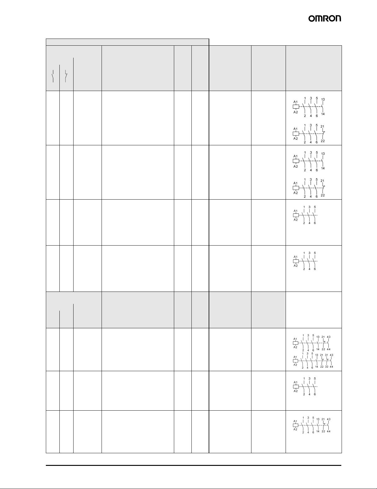
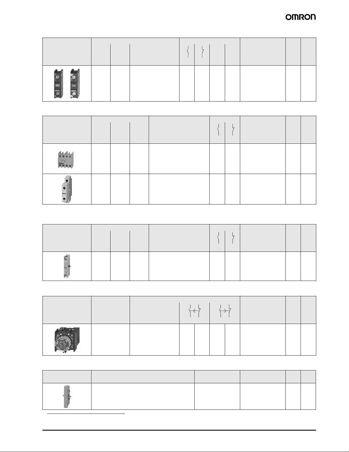
Wiring diagrams
Auxiliary contact blocks Pneumatic timer
J73KN-B-10 J73KN-B-01 J73KN-C-11S
(left side) (right side)
53 61
54 62
J73KN-D-11 J73KN-D-11S J73KN-D-22
*1
Correct terminal marking is given by mounting
*1
71 83
72 84
on-delayed off-delayed
J74KN-B-TP...DA J74KN-B-TP...IA
50 Motor Contactor J7KN
Page 27

■ Dimensions
AC operated DC operated
J7KN-10/14/18/22(-4)... J7KN-10/14/18/22...D
45
35-36
Ø5
59
49-50
M3.5
J7KN-24/32/40... J7KN-24/32/40...D
45
1010
35
82.5
78.5
6.5
50
J7KNG-10/14/18/22(-4)...D
45
35
89
80
104.5
100.5
111
107
Ø4.5
M3.5
6.5
79
Ø4,5
65
60
74
M5
6.5
63
J7KNG-24/32/40...D
80
89
J7KN-50/62/74... J7KN-50/62/74...D
10 10
95
100
110
60
50
Ø5.5
113
109
45 1010
35
›4.5
M5
6.5
125
121
86
Auxiliary contacts are optional
M6
7.5
68
Motor Contactor J7KN 51
Page 28

AC and DC operated
J7KN-85...
J7KN-110...
J7KN-151...
J7KN-176...
12 x 70
Auxiliary contacts are optional
J7KN-200...
Pneumatic timer
J74KN-B-TP...
52 Motor Contactor J7KN
Page 29

Auxiliary contact blocks
J74KN-A-VG J74KN-D
28
23
4
J74KN-B-VG J74KN-B-RC
150
65
11
J74KN-C
10010 19
10
24
7
Motor Contactor J7KN 53
Page 30

Position of Terminals
AC operated
J7KN-10-10
to
J7KN-22-10
DC operated with double winding coil
J7KN-10-10...D
J7KN-14-10...D
J7KN-18-10...D
J7KN-22-10...D
J7KN-10-01
to
J7KN-22-01
J7KN-10-01...D
J7KN-14-01...D
J7KN-18-01...D
J7KN-22-01...D
J7KN-24
J7KN-32
J7KN-40
J7KN-24...D
J7KN-32...D
J7KN-40...D
J7KN-50
J7KN-62
J7KN-74
J7KN-50...D
J7KN-62...D
J7KN-74...D
J7KN-85-22
J7KN-110-22
J7KN-85-21...D
J7KN-110-21...D
AC and DC operated DC operated
J7KN-151
J7KN-176
J7KN-200-21
J7KNG-10-10
J7KNG-14-10
J7KNG-18-10
J7KNG-22-10
J7KNG-10-01
J7KNG-14-01
J7KNG-18-01
J7KNG-22-01
J7KNG-24
J7KNG-32
J7KNG-40
3 L2 5 L3
1 L1
4 T22 T1
A1 A2
A2A1
6 T3
Do not use/install these products before having read the applicable precautions as listed in Cat. No. J09-EN-01
available from www.europe.omron.com or on request from OMRON local sales office.
ALL DIMENSIONS SHOWN ARE IN MILLIMETERS.
Cat. No. J06E-EN-01A
In the interest of product improvement, specifications are subject to change without notice.
54 Motor Contactor J7KN
 Loading...