

Page 1

HS-360X Handheld DPM Scanner
User Manual
P/N 84-9000360-02 Rev A
Page 2

Copyright and Disclaimers
Copyright ©2018
Omron Microscan Systems, Inc.
Tel: +1.425.226.5700 / 800.762.1149
Fax: +1.425.226.8250
All rights reserved. The information contained herein is proprietary and is provided solely for the purpose
of allowing customers to operate and/or service Omron Microscan-manufactured equipment and is not to
be released, reproduced, or used for any other purpose without written permission of Omron Microscan.
Throughout this manual, trademarked names might be used. We state herein that we are using the names
to the benefit of the trademark owner, with no intention of infringement.
Disclaimer
The information and specifications described in this manual are subject to change without notice.
Latest Manual Version
For the latest version of this manual, see the Download Center on our web site at:
www.microscan.com/downloadcenter
.
Technical Support
For technical support, e-mail: helpdesk@microscan.com.
Warranty
For current warranty information, see: www.microscan.com/warranty.
Omron Microscan Systems, Inc.
United States Corporate Headquarters
+1.425.226.5700 / 800.762.1149
United States Northeast Technology Center
+1.603.598.8400 / 800.468.9503
European Headquarters
+31.172.423360
Asia Pacific Headquarters
+65.6846.1214
ii HS-360X Handheld DPM Scanner User Manual
Page 3

Introduction
No part of this publication may be reproduced or used in any form, or by any electrical or mechanical means, without
permission in writing from Omron Microscan. This includes electronic or mechanical means, such as photocopying,
recording, or information storage and retrieval systems. The material in this manual is subject to change without notice.
The software is provided strictly on an “as is” basis. All software, including firmware, furnished to the user is on a
licensed basis. Omron Microscan grants to the user a non-transferable and non-exclusive license to use each
software or firmware program delivered hereunder (licensed program). Except as noted below, such license may
not be assigned, sublicensed, or otherwise transferred by the user without prior written consent of Omron
Microscan. No right to copy a licensed program in whole or in part is granted, except as permitted under copyright
law. The user shall not modify, merge, or incorporate any form or portion of a licensed program with other program
material, create a derivative work from a licensed program, or use a licensed program in a network without written
permission from Omron Microscan. The user agrees to maintain Omron Microscan’s copyright notice on the
licensed programs delivered hereunder, and to include the same on any authorized copies it makes, in whole or in
part. The user agrees not to decompile, disassemble, decode, or reverse engineer any licensed program delivered
to the user or any portion thereof.
Omron Microscan reserves the right to make changes to any product to improve reliability, function, or design.
Omron Microscan does not assume any product liability arising out of, or in connection with, the application or use
of any product, circuit, or application described herein. No license is granted, either expressly or by implication,
estoppel, or otherwise under any patent right or patent, covering or relating to any combination, system, apparatus,
machine, material, method, or process in which Omron Microscan products might be used. An implied license
exists only for equipment, circuits, and subsystems contained in Omron Microscan products.
This product may include Seller Software, Third Party Software, and/or Publicly Available Software.
Use of any Software is subject to the applicable licenses, terms and conditions of the agreement in force between
you and the Seller unless a separate License is included, in which case, use of the Software will be governed by the
separate License.
Copies of the licenses for the following Publicly Available Software, and all attributions, acknowledgments, and
software information details, are included below. Seller is required to reproduce the software licenses,
acknowledgments and copyright notices as provided by the Authors and Owners. The information is provided in its
native language form, without modification or translation.
Publicly available software list:
Name: Regular Expression Evaluator
Version: 8.3
Description: Compiles and executes regular expressions.
Software Site: http://www.freebsd.org/cgi/cvsweb.cgi/src/lib/libc/regex/
Source Code: No Source Distribution Obligations. Seller will not provide nor distribute the Source Code for the
Regular Expression Evaluator.
License: BSD Style License
©1992 Henry Spencer.
©1992, 1993 The Regents of the University of California. All rights reserved.
This code is derived from software contributed to Berkeley by Henry Spencer of the University of Toronto.
Redistribution and use in source and binary forms, with or without modification, are permitted provided that the
following conditions are met:
1. Redistributions of source code must retain the above copyright notice, this list of conditions and the following disclaimer.
2. Redistributions in binary form must reproduce the above copyright notice, this list of conditions and the following
disclaimer in the documentation and/or other materials provided with the distribution.
3. All advertising materials mentioning features or use of this software must display the following acknowledgment:
This product includes software developed by the University of California, Berkeley and its contributors.
4. Neither the name of the University nor the names of its contributors may be used to endorse or promote products
derived from this software without specific prior written permission.
THIS SOFTWARE IS PROVIDED BY THE REGENTS AND CONTRIBUTORS ``AS IS'' AND ANY EXPRESS OR
IMPLIED WARRANTIES, INCLUDING, BUT NOT LIMITED TO, THE IMPLIED WARRANTIES OF
MERCHANTABILITY AND FITNESS FOR A PARTICULAR PURPOSE ARE DISCLAIMED. IN NO EVENT SHALL
THE REGENTS OR CONTRIBUTORS BE LIABLE FOR ANY DIRECT, INDIRECT, INCIDENTAL, SPECIAL,
EXEMPLARY, OR CONSEQUENTIAL DAMAGES (INCLUDING, BUT NOT LIMITED TO, PROCUREMENT OF
SUBSTITUTE GOODS OR SERVICES; LOSS OF USE, DATA, OR PROFITS; OR BUSINESS INTERRUPTION)
HOWEVER CAUSED AND ON ANY THEORY OF LIABILITY, WHETHER IN CONTRACT, STRICT LIABILITY, OR
TORT (INCLUDING NEGLIGENCE OR OTHERWISE) ARISING IN ANY WAY OUT OF THE USE OF THIS
SOFTWARE, EVEN IF ADVISED OF THE POSSIBILITY OF SUCH DAMAGE.
HS-360X Handheld DPM Scanner User Manual iii
Page 4

Table of Contents
Table of Contents
Introduction
Table of Contents .......................................................................................iv
About This Manual ................................................................................... viii
HS-360X Configurations.............................................................................ix
Service Information .....................................................................................x
Chapter 1 Quick Start
HS-360X Handheld DPM Scanner .......................................................... 1-2
HS-360X Wireless Handheld DPM Scanner ........................................... 1-4
HS-360X Wired Handheld DPM Scanner.............................................. 1-14
Chapter 2 Data Capture
HS-360X Wireless Scanner Beeper and LED ......................................... 2-2
HS-360X Beeper and LED Definitions .................................................... 2-7
HS-360X Scanning.................................................................................. 2-8
Chapter 3 Maintenance and Technical Specifications
Maintenance............................................................................................ 3-2
Troubleshooting....................................................................................... 3-4
Technical Specifications.......................................................................... 3-7
HS-360X Wired Scanner Signal Descriptions ....................................... 3-10
Chapter 4 Radio Communications
HS-360X Wireless Scanner Radio Communications............................... 4-2
Radio Communications Parameter Defaults ........................................... 4-3
Wireless Beeper Definitions .................................................................... 4-5
Radio Communications Host Types ........................................................ 4-5
Bluetooth-Friendly Name......................................................................... 4-9
Wi-Fi Friendly Mode .............................................................................. 4-11
Radio Output Power .............................................................................. 4-14
Bluetooth Radio State ........................................................................... 4-16
HID Host Parameters ............................................................................ 4-17
Reconnect Attempt Beep Feedback...................................................... 4-29
Out-of-Range Indicator.......................................................................... 4-34
Beep on <BEL> ..................................................................................... 4-36
Scanner(s)-to-Cradle Support ............................................................... 4-37
Batch Mode ........................................................................................... 4-46
Persistent Batch Storage....................................................................... 4-50
Page Button........................................................................................... 4-51
Page Options......................................................................................... 4-52
Classic Bluetooth and/or Low Energy (Cradle Host Only)..................... 4-54
Bluetooth Security ................................................................................. 4-55
Bluetooth Radio, Linking, and Batch Operation ................................... 4-59
iv HS-360X Handheld DPM Scanner User Manual
Page 5

Chapter 5 User Preferences and Miscellaneous Options
Introduction..............................................................................................5-2
Scanning Sequence Examples................................................................5-2
Errors While Scanning............................................................................. 5-2
Parameter Defaults.................................................................................. 5-3
User Preferences..................................................................................... 5-5
Chapter 6 Imaging Preferences
Introduction..............................................................................................6-2
Scanning Sequence Examples................................................................6-3
Errors While Scanning............................................................................. 6-3
Imaging Preferences Parameter Defaults ............................................... 6-3
Chapter 7 USB Interface
Connecting a USB Interface ...................................................................7-2
USB Parameter Defaults .........................................................................7-5
USB Host Parameters .............................................................................7-6
Optional USB Parameters ................................................................ .....7-20
ASCII Character Set for USB ................................................................7-26
Chapter 8 RS-232 Interface
Introduction..............................................................................................8-2
Connecting an RS-232 Interface .............................................................8-3
RS-232 Parameter Defaults ....................................................................8-5
ASCII Character Set for RS-232............................................................8-23
Introduction
Chapter 9 Symbologies
Introduction..............................................................................................9-2
Scanning Sequence Examples................................................................9-2
Errors While Scanning............................................................................. 9-2
Symbology Parameter Defaults...............................................................9-3
Enable/Disable All Code Types ............................................................... 9-8
UPC/EAN.................................................................................................9-9
Code 128 ............................................................................................... 9-36
Code 39 .................................................................................................9-48
Code 93 .................................................................................................9-60
Code 11 .................................................................................................9-63
Interleaved 2 of 5 (ITF) ..........................................................................9-68
Discrete 2 of 5 (DTF) .............................................................................9-77
Codabar (NW - 7) ..................................................................................9-80
MSI ........................................................................................................9-86
Chinese 2 of 5 ....................................................................................... 9-92
Matrix 2 of 5...........................................................................................9-93
Korean 3 of 5 ......................................................................................... 9-98
Inverse 1D ............................................................................................. 9-99
GS1 DataBar .......................................................................................9-100
HS-360X Handheld DPM Scanner User Manual v
Page 6

Table of Contents
BC412 ................................................................................................. 9-105
Composite ........................................................................................... 9-106
PDF417 ............................................................................................... 9-112
MicroPDF417 ...................................................................................... 9-113
Code 128 Emulation............................................................................ 9-114
Data Matrix .......................................................................................... 9-115
GS1 Data Matrix.................................................................................. 9-115
Data Matrix Inverse ............................................................................. 9-116
Maxicode ............................................................................................. 9-117
QR Code ............................................................................................. 9-118
GS1 QR............................................................................................... 9-119
Micro QR Code.................................................................................... 9-120
Aztec ................................................................................................... 9-121
Aztec Inverse....................................................................................... 9-122
Han Xin................................................................................................ 9-123
Han Xin Inverse................................................................................... 9-124
DotCode .............................................................................................. 9-125
U.S. Postnet ........................................................................................ 9-126
U.S. Planet .......................................................................................... 9-127
UK Postal ............................................................................................ 9-129
Japan Postal........................................................................................ 9-131
Australia Post ...................................................................................... 9-132
Netherlands KIX Code......................................................................... 9-135
USPS 4CB/One Code/Intelligent Mail ................................................. 9-136
UPU FICS Postal................................................................................. 9-137
Mailmark.............................................................................................. 9-138
Symbology-Specific Security Levels ................................................... 9-139
Report Version .................................................................................... 9-145
Macro PDF Features ........................................................................... 9-146
Chapter 10 WebLink
Set Up HS-360X Host Interface ............................................................ 10-2
Install WebLink
Connect to WebLink
Explore the Start View........................................................................... 10-5
Create a New Setup or Load an Existing Setup.................................... 10-6
Explore the Setup View......................................................................... 10-7
Configure Cycle Settings....................................................................... 10-8
Configure Performance Settings ........................................................... 10-9
Configure Symbology and Decode Settings........................................ 10-12
Configure Output Formatting............................................................... 10-14
Run the Application ............................................................................. 10-16
vi HS-360X Handheld DPM Scanner User Manual
PC
.................................................................................. 10-3
PC
.......................................................................... 10-4
PC
Page 7

Introduction
Appendices
Appendix A — Standard Default Parameters .................................................A-2
Appendix B — Country Codes......................................................................A-11
Appendix C — Country Code Pages ............................................................A-31
Appendix D — Chinese, Japanese, and Korean (CJK) Decode Control ......A-44
Appendix E — Programming Reference.......................................................A-53
Appendix F — Sample Symbols ...................................................................A-59
Appendix G — Alphanumeric Keyboard .......................................................A-62
Appendix H — Numberic Keyboard..............................................................A-77
Appendix I — ASCII Character Sets.............................................................A-79
Appendix J — Non-Parameter Attributes......................................................A-90
HS-360X Handheld DPM Scanner User Manual vii
Page 8

Table of Contents
* HID Keyboard Emulation
Feature/Option
* Indicates Default
About This Manual
The HS-360X Handheld DPM Scanner User Manual provides general instructions for setting up,
operating, maintaining, and troubleshooting wireless and wired HS-360X scanners.
Notational Conventions
The following conventions are used in this document:
Italics are used to highlight the following:
• Chapters and sections in this and related documents;
• Dialog box, window and screen names;
• Drop-down list and list box names;
• Check box and radio button names.
Bold text is used to highlight the following:
• Key names on a keypad;
• Button names on a screen.
Bullets (•) indicate:
• Action items;
• Lists of alternatives.
Lists of required steps that are not necessarily sequential:
• Sequential lists (e.g., those that describe step-by-step procedures) appear as numbered lists.
• Throughout the programming barcode menus, asterisks (*) are used to denote default
parameter settings.
Related Documents
• HS-360X Wired Scanner Quick Start Guide, P/N 83-9310013-02, provides general
information about how to get started with the wired version of the HS-360X Handheld
DPM Scanner, and includes basic instructions for setup and operation.
• HS-360X Wireless Scanner Quick Start Guide, P/N 83-9310014-02, provides general
information
DPM Scanner,
• HS-360X Four-Slot Spare Battery Charger Quick Start Guide, P/N 83-93100017-02,
provides general information about how to mount, configure, and use the HS-360X
Four-Slot Spare Battery Charger.
•
HS-360X Cradle Quick Start Guide, P/N 83-93100018-02, provides general information
about how to mount, connect, configure, and use the HS-360X Cradle.
For the latest version of all guides, visit the Download Center at: www.microscan.com.
viii HS-360X Handheld DPM Scanner User Manual
about how to get started with the wireless version of the HS-360X Handheld
and includes basic instructions for setup and operation.
Page 9

Introduction
HS-360X Configurations
This guide includes the following HS-360X configurations:
Part Number Description
HDS-3678-0001 Handheld DPM Scanner, Wireless, HS-360X
HDS-3608-0001 Handheld DPM Scanner, Wired, HS-360X
HS-360X Accessories, Cables, and Power Supplies
Caution: Use only cables designed for the HS-360X Handheld DPM Scanner.
Part Number Description
HS-360X Wireless Handheld DPM Scanner
Accessories
12-9000937-01 Cradle, Charger, Sealed, HS-360X
98-9000224-01 Battery, Spare, HS-360X – Included
98-9000185-01 Kit, Battery Charger, 4-Slot, HS-360X
USB Cables
12-9000942-01 Cable, USB, Shielded, 2 M, EXT 12V, HS-360X
12-9000943-01 Cable, USB, Shielded, 4.6 M, EXT 12V, HS-360X (Requires 12V Power Supply)
12-9000946-01 Cable, USB, Shielded, 2 M, HS-360X
12-9000947-01 Cable, USB, Shielded, 4.6 M, HS-360X
RS-232 Cables
12-9000953-01 Cable, RS-232, DB9 Socket, 2 M, Straight, HS-360X
Power Supplies
98-9000181-01 Kit, Power Supply, Cradle, HS-360X
98-9000182-01 Kit, Power Supply, Battery Charger, 4-Slot, HS-360X
12-9000959-01 AC Power Cord, 2.5 M, U.S., C13 Conn.
12-9000960-01 AC Power Cord, 2.5 M, EU, C13 Conn.
12-9000961-01 AC Power Cord, 2.5 M, UK, C13 Conn.
12-9000962-01 AC Power Cord, 2.5 M, China, C13 Conn.
HS-360X Wired Handheld DPM Scanner
Accessories
98-9000186-01 Kit, HS-360X Stand
USB Cables
12-9000942-01 Cable, USB, Shielded, 2 M, EXT 12V, HS-360X
12-9000943-01 Cable, USB, Shielded, 4.6 M, EXT 12V, HS-360X (Requires 12V Power Supply)
12-9000946-01 Cable, USB, Shielded, 2 M, HS-360X
12-9000947-01 Cable, USB, Shielded, 4.6 M, HS-360X
RS-232 Cables
12-9000953-01 Cable, RS-232, DB9 Socket, 2 M, Straight, HS-360X
Power Supplies
98-9000181-01 Kit, Power Supply, Cradle, HS-360X
12-9000959-01 AC Power Cord, 2.5 M, U.S., C13 Conn.
12-9000960-01 AC Power Cord, 2.5 M, EU, C13 Conn.
12-9000961-01 AC Power Cord, 2.5 M, UK, C13 Conn.
12-9000962-01 AC Power Cord, 2.5 M, China, C13 Conn.
HS-360X Handheld DPM Scanner User Manual ix
Page 10

Table of Contents
Service Information
If you have a problem using the equipment, contact your facility's technical or systems
support. If there is a problem with the equipment, you can contact customer service at:
www.microscan.com.
When contacting support, please have the following information available:
• Serial number of the unit
• Model number or product name
• Software type and version number
Omron Microscan responds to calls by e-mail, telephone or fax within the time limits set forth
in service agreements.
If your problem cannot be solved by support, you may need to return your equipment for
servicing and will be given specific directions. Omron Microscan is not responsible for any
damages incurred during shipment if the approved shipping container is not used. Shipping
the units improperly can possibly void the warranty.
If you purchased your product from an Omron Microscan business partner, please contact
that partner for support.
x HS-360X Handheld DPM Scanner User Manual
Page 11

1 Quick Start
This section provides a product overview, unpacking instructions, and configuration information.
HS-360X Handheld DPM Scanner User Manual 1-1
Page 12
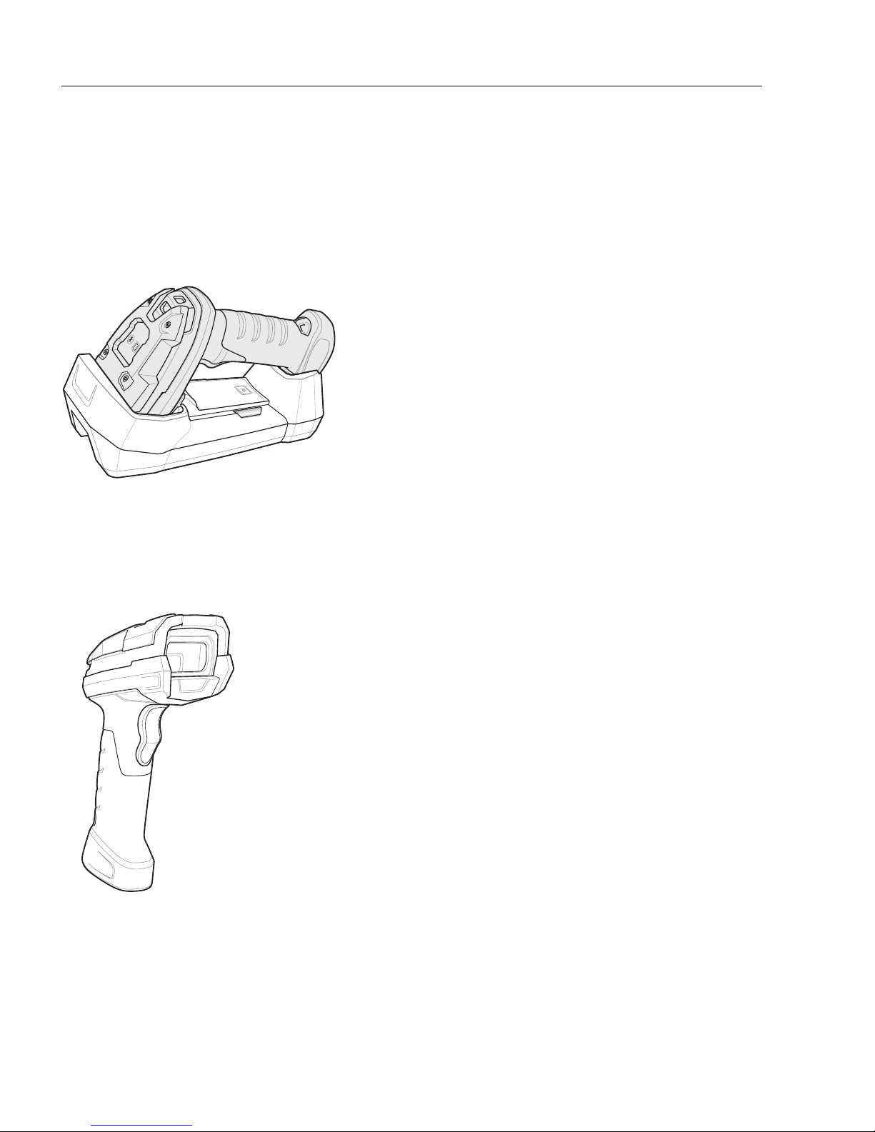
HS-360X Handheld DPM Scanner
HS-360X Wireless Handheld DPM Scanner
HS-360X Wired Handheld DPM Scanner
HS-360X Handheld DPM Scanner
The wireless HS-360X combines superior 1D and 2D omnidirectional barcode scanning
performance and advanced ergonomics in a lightweight design. The scanner design ensures
comfort and ease of use over extended periods of time.
Important: A PowerPrecision+ 3100 mAh Li-Ion rechargeable battery is included with wireless
versions of the HS-360X.
The wired HS-360X combines superior 1D and 2D omnidirectional barcode scanning performance
and advanced ergonomics in a lightweight, hands-free / handheld design. The HS-360X
Stand seamlessly accommodates both countertop and handheld use.
1-2 HS-360X Handheld DPM Scanner User Manual
Page 13

Quick Start
The HS-360X Handheld DPM Scanner Supports:
• USB connection to a host. The scanner autodetects a USB host and defaults to HID
keyboard. Select other USB interface types by scanning programming symbol menus.
The USB interface supports the following international keyboards for a Windows
environment: North American English, Japanese, German, French, French Canadian,
Spanish, Italian, Swedish, UK English, and Brazilian Portuguese.
• Standard RS-232 connection to a host. Scan programming symbol menus to set up
communication between the scanner with the host.
Important: An RS-232 connection is not compatible with WebLink
software, and offers only limited programming options.
configuration
PC
®
• Configuration via WebLink
PC
.
Unpacking
Remove the scanner from its packaging and inspect it for damage. If the scanner was damaged
during shipping, contact Omron Microscan support.
comprise the approved shipping container, which you can use to return the scanner for servicing.
KEEP THE PACKING MATERIALS
. They
HS-360X Handheld DPM Scanner User Manual 1-3
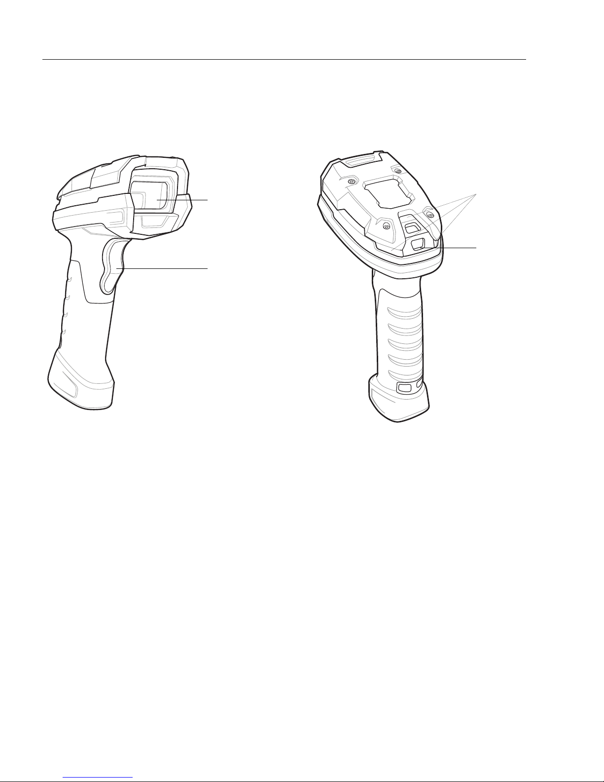
Page 14
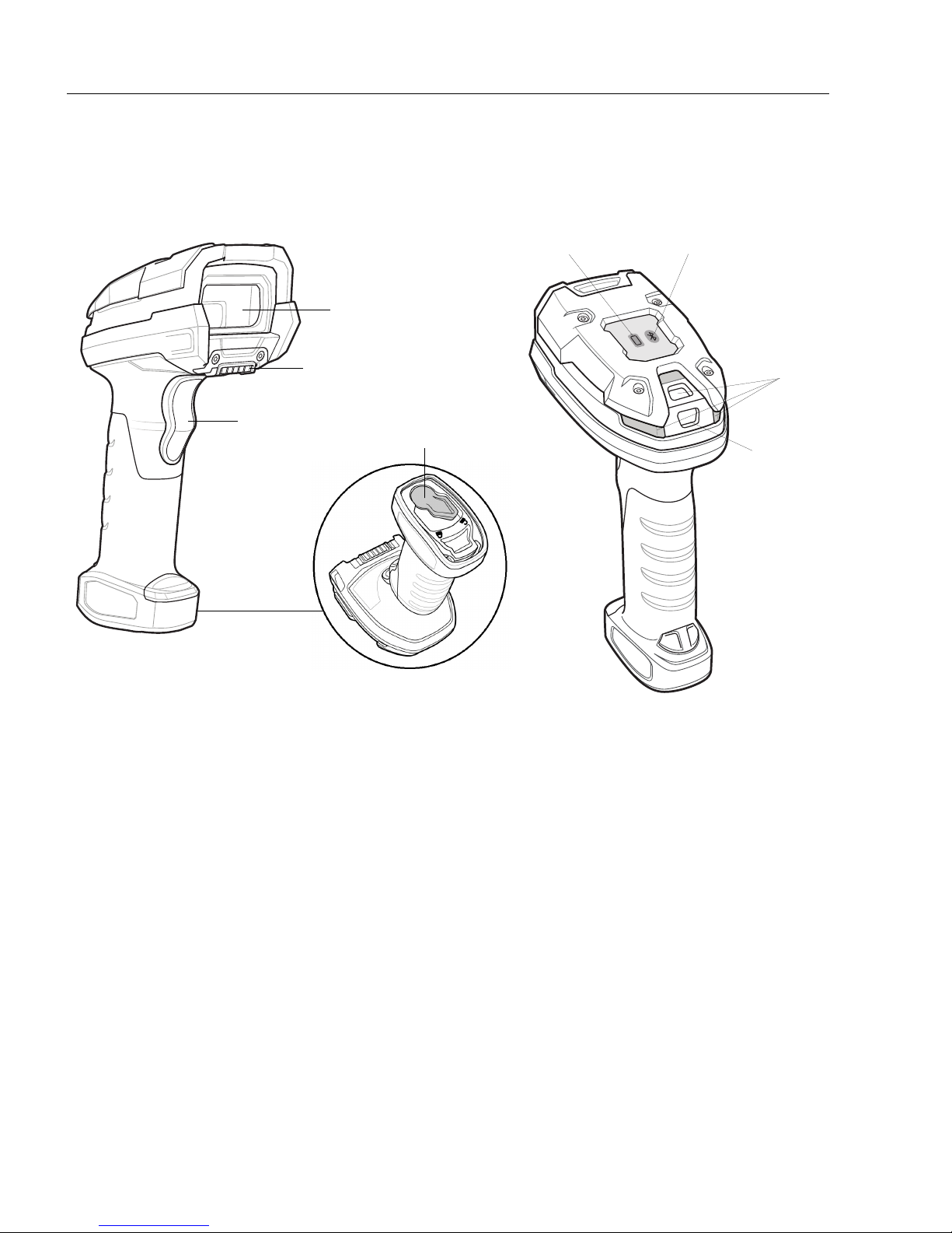
HS-360X Wireless Handheld DPM Scanner
Beeper
LEDs
Trigger
Scan Window
Battery LED
Radio LED
Battery Latch
Charging/Communication
Contacts
HS-360X Wireless Handheld DPM Scanner
Parts
1-4 HS-360X Handheld DPM Scanner User Manual
Page 15
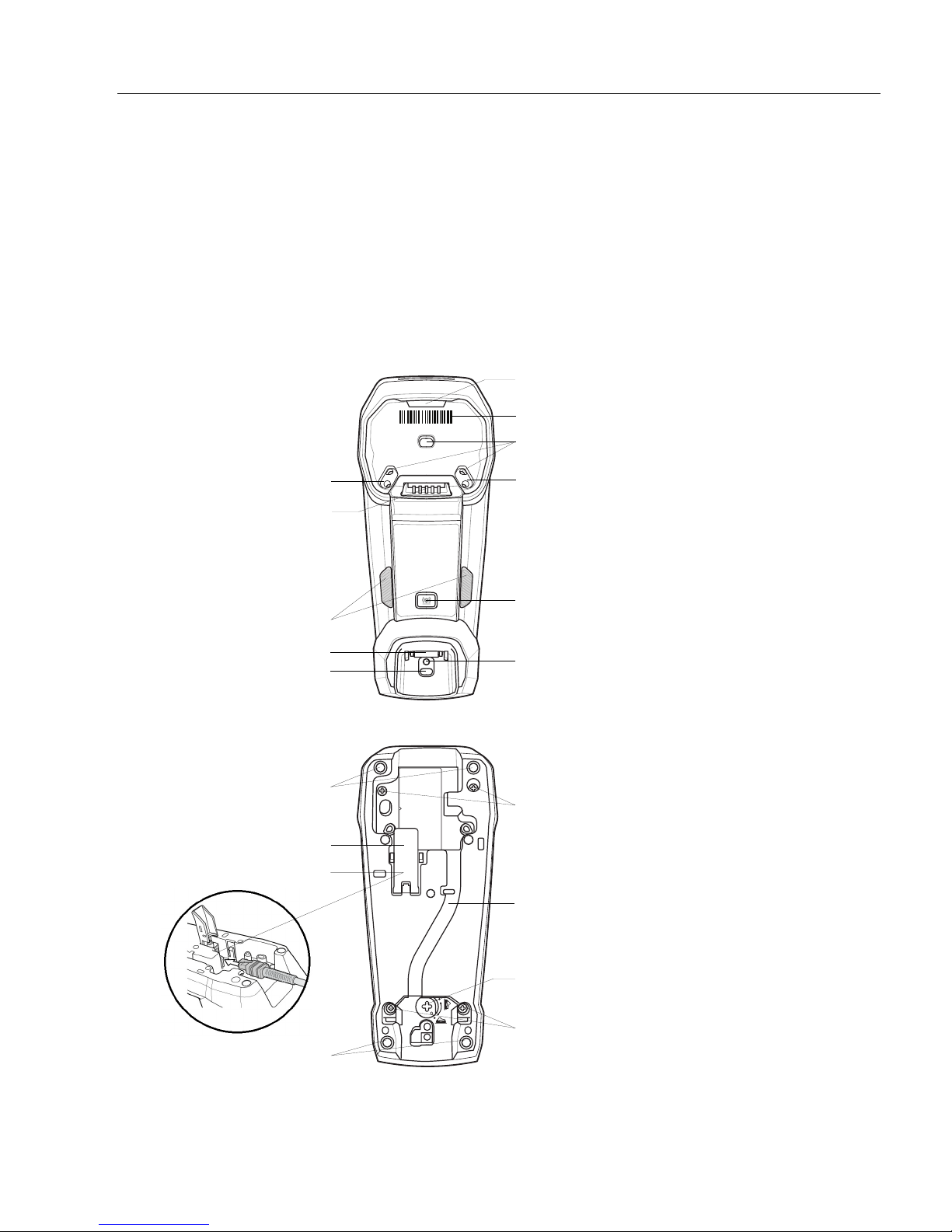
Quick Start
Charging/Communications
Contacts
Pairing Barcode
Mounting Screw Hole
Foot Latch
LEDs
Mounting Screw Hole
Drain Holes
Canopy Latch
Mounting Screw Hole
Page Button
Drain Hole
Rubber Feet
Host Cable Guide
Foot Latch Release
Mounting Screw Holes
Mounting Screw Holes
Host Cable Latch
Host Cable (Under Latch)
Rubber Feet
The HS-360X Cradle
The HS-360X Cradle is a charger, radio communication interface, and host communication
interface for the HS-360X Wireless Scanner.
The wireless cradle charges the scanner and provides host communication by receiving
data via a Bluetooth radio, and sending that data to the host through an attached cable. An
external
power supply or a powered host cable provides power to the cradle.
For more mounting options, refer to the HS-360X Cradle Quick Start Guide, P/N 83-9310018-02,
included with the cradle.
Cradle – Front View
PAIR
scanner
Cradle – Back View
HS-360X Handheld DPM Scanner User Manual 1-5
Page 16
HS-360X Wireless Handheld DPM Scanner
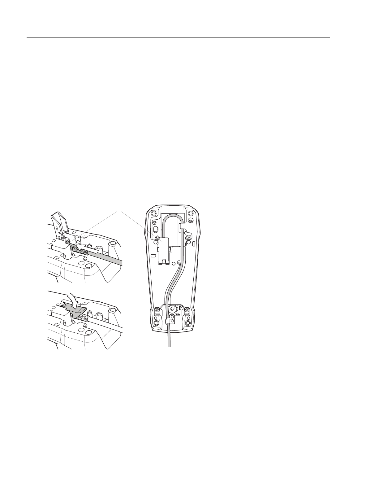
Connecting the Cables to the Cradle
Latch
Host Port
(Under Latch)
Important: Be sure that the
interface cable is pushed all
the way into the host port
before you close the latch.
Connecting the Cradle
Note: The interface cable and power supply (if necessary) in the following order to ensure
proper operation of the scanner and cradle.
To connect the HS-360X Cradle:
1. Connect the appropriate cable to the power supply and an AC power source, if necessary.
2. Insert the interface cable into the host port.
3. Lift the latch and connect the interface cable into the cradle's host port and then close
the latch.
4. If applicable, thread the interface cable over the cable support hook and run the host
cable into the cable groove.
5. Pair the scanner to the cradle either by inserting it in the cradle (if pair on contacts is
enabled), or by scanning the pairing symbol.
6. If necessary, scan the appropriate host symbol (for non-autodetected interfaces). See
the specific host chapter.
Note: Always disconnect the DC power supply BEFORE disconnecting the cable to
the host end or the cradle may not recognize the new host.
Note: Different cables are required for different hosts. The connectors illustrated in
each host chapter are examples only. The connectors may be different from those
illustrated, but the steps to connect the scanner remain the same.
1-6 HS-360X Handheld DPM Scanner User Manual
Page 17

Quick Start
Supplying Power to the Cradle
The cradle receives power from one of two sources:
• An external power supply.
• When connected to the host through an interface cable that supplies power.
The cradle detects whether the host or the external supply is supplying power. It always
draws power from the external supply when available, regardless of the presence of power
from a host.
Mounting the Cradle
For information on mounting the cradle, refer to the documentation included with the cradle.
Wireless HS-360X Battery
Battery Statistics Capabilities
The HS-360X Wireless Scanner is equipped with PowerPrecision+ batteries. These
intelligent batteries have the integrated technology required to collect the detailed real-time
battery metrics needed to maximize useful battery life and ensure every battery is healthy
and able to hold a full charge.
PowerPrecison+ batteries support the following remote management functionality:
• Battery Asset Information
• Manufacture Date of Battery
• Serial Number of Battery
• Model Number of Battery
• Firmware Version of Battery
• Design Capacity
• Battery Life Statistics
• State of Health Meter
• Charge Cycles Consumed
• Battery Status (at Time of Poll)
• State of Charge
• Remaining Capacity
• Charge Status
• Remaining Time to Complete Charging
• Battery Voltage / Current
• Battery Temperature
• Present / Highest / Lowest
Battery statistics can be viewed in WebLink
1. Select Wireless Scanner in the Start menu.
2. From the Advanced Settings menu, go to the Battery tab.
Hint: ALT+A opens the Advanced Settings tab for the selected scanner.
by following these steps:
PC
HS-360X Handheld DPM Scanner User Manual 1-7
Page 18
HS-360X Wireless Handheld DPM Scanner
Unlock
Lock
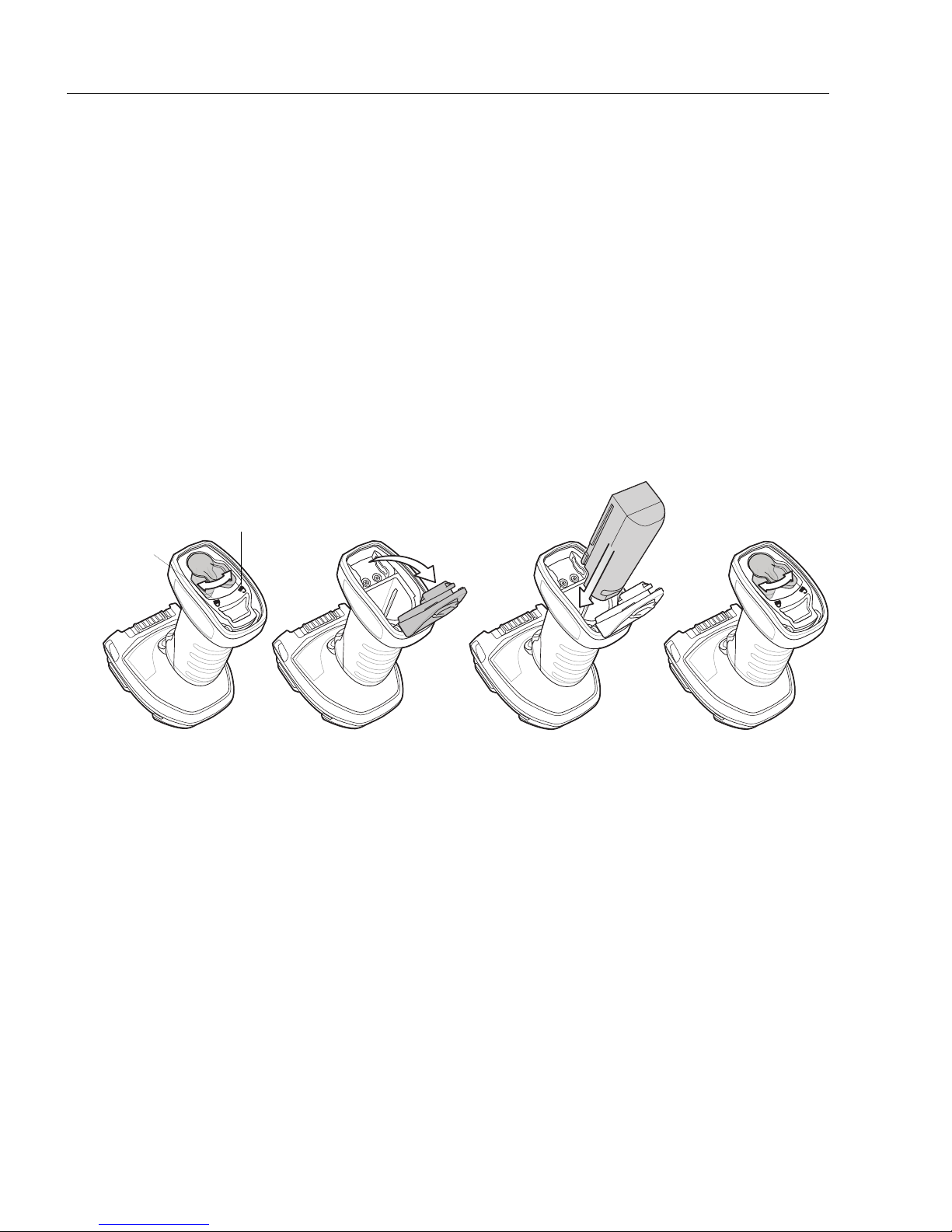
Inserting the Battery
Inserting the Wireless HS-360X Battery
A PowerPrecision+ 3100 mAh Li-Ion rechargeable battery ships with each wireless HS-360X.
Batteries are shipped in an Off mode and do not power the scanner. After inserting a new
battery into the HS-360X scanner, you must insert the scanner into a cradle for the battery to
turn On.
Alternatively, the battery can be placed in the four slot spare battery charger to charge and
then inserted in the scanner for immediate use.
The battery resides in a chamber in the scanner handle. To insert the battery:
1. Lightly press down and slide the locking lever counterclockwise to unlock and
release the battery door.
2. Open the battery door.
3. If a battery is already installed, turn the scanner upright to slide the battery out.
4. Slide the new battery into the chamber, with the rounded side toward the back and
the contacts facing into the chamber.
1. Close the battery door.
2. Lightly press down and slide the locking lever clockwise to lock the battery door.
3. If using a brand new battery, insert the scanner into a cradle to turn the battery on.
Removing the HS-360X Battery
To remove the battery:
1. Lightly press down and slide the locking lever counterclockwise to unlock the battery door.
2. Open the battery door.
3. Turn the scanner upright to slide the battery out.
1-8 HS-360X Handheld DPM Scanner User Manual
Page 19

Quick Start
Inserting the Scanner in the Cradle
Charging the HS-360X Battery
When using a new battery in the HS-360X, the battery requires a charge to be enabled.
Insert the battery in the HS-360X and place the HS-360X in the cradle.
The battery begins charging when the cradle’s LED indicator starts blinking amber. The
HS-360X’s battery has completed a charge when the cradle’s LED indicator is solid green. A
complete charge of a fully discharged battery can take up to three hours using external
power and up to ten hours using USB power over the USB interface cable.
To avoid a battery temperature fault, always charge the battery in the scanner within the
recommended temperature of 32° to 104° F (0° to 40° C) nominal, 41° to 95° F (5° to 35° C) ideal.
Inserting the HS-360X Scanner in the Cradle
To insert the scanner in the cradle:
1. Insert the scanner into the cradle top first.
2.
Push the handle until it clicks into place, engaging the contacts in the cradle and scanner.
HS-360X Handheld DPM Scanner User Manual 1-9
Page 20

HS-360X Wireless Handheld DPM Scanner
Sending Data to the Host Computer
The cradle receives data from the scanner via a wireless radio connection and transmits it to
the host computer via the host cable. The scanner and cradle must be paired for successful
wireless communication.
Pairing
Pairing registers a scanner to the cradle such that the scanner and cradle can exchange
information. The cradle operates in two modes: Point-to-Point and Multipoint-to-Point. In
Point-to-Point mode, pair the scanner to the cradle either by inserting it in the cradle (if pair
on contacts is enabled), or by scanning the pairing symbol. In Multipoint-to-Point mode, you
can pair up to seven scanners to one cradle.
To pair the scanner with the cradle, scan a pairing symbol. A high-low-high-low beep sequence
followed by a low-high beep sequence indicates successful pairing and connection to the
remote device. A long low, long high beep sequence indicates unsuccessful pairing.
The pairing symbol that connects the scanner to a cradle is unique to each cradle.
Do not scan data or parameters until pairing completes.
Lost Connection to Host
If scanned data does not transmit to the cradle's host, ensure that all cables are firmly
inserted and the power supply is connected to an appropriate AC outlet, if applicable. If
scanned data still does not transmit to the host, reestablish a connection with the host:
1. Disconnect the power supply from the cradle.
2. Disconnect the host interface cable from the cradle.
3. Wait three seconds.
4. Reconnect the host interface cable to the cradle.
5. Reconnect the power supply to the cradle, if the host requires.
6. Reestablish pairing with the cradle by scanning the pairing symbol.
Configuring the Scanner
Use the configuration symbols in this manual or the WebLink
configure the scanner.
Radio Communications
The scanner can communicate with remote devices via Bluetooth, or by pairing with a cradle.
1-10 HS-360X Handheld DPM Scanner User Manual
configuration program to
PC
Page 21
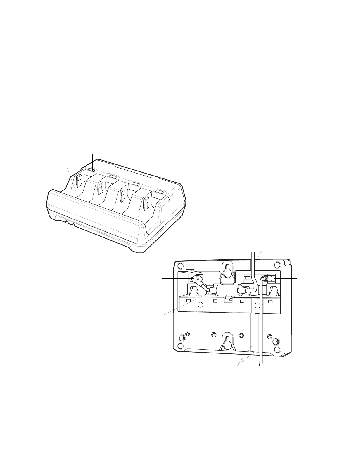
Quick Start
Battery Charging LED (four)
Battery
Well
(four)
Power Cable
Groove
Wall Mount
Key-Hole (two)
Rubber Feet (four)
Power Port
Cable Groove(s)
Power
Cable Well
USB Port
Four-Slot Spare
Battery Charger
Four-Slot Spare Battery Charger
The battery charger can accomodate up to four single spare batteries. The charger can sit
on a desktop or be mounted on a wall. This document provides basic instructions for charger
set up and use.
For best performance, fully charge the device battery before using the device for the first
time. To charge the
device battery, insert the battery in the cradle. The battery begins charging when the LED
indicator on the battery charger starts flashing amber. A complete charge of a fully discharged
battery can take up to five hours. Charge within the recommended temperature of 32° to
104° F (0° C to 40° C) nominal, 41° to 95° F (5° to 35° C) ideal.
HS-360X Handheld DPM Scanner User Manual 1-11
Page 22
HS-360X Wireless Handheld DPM Scanner
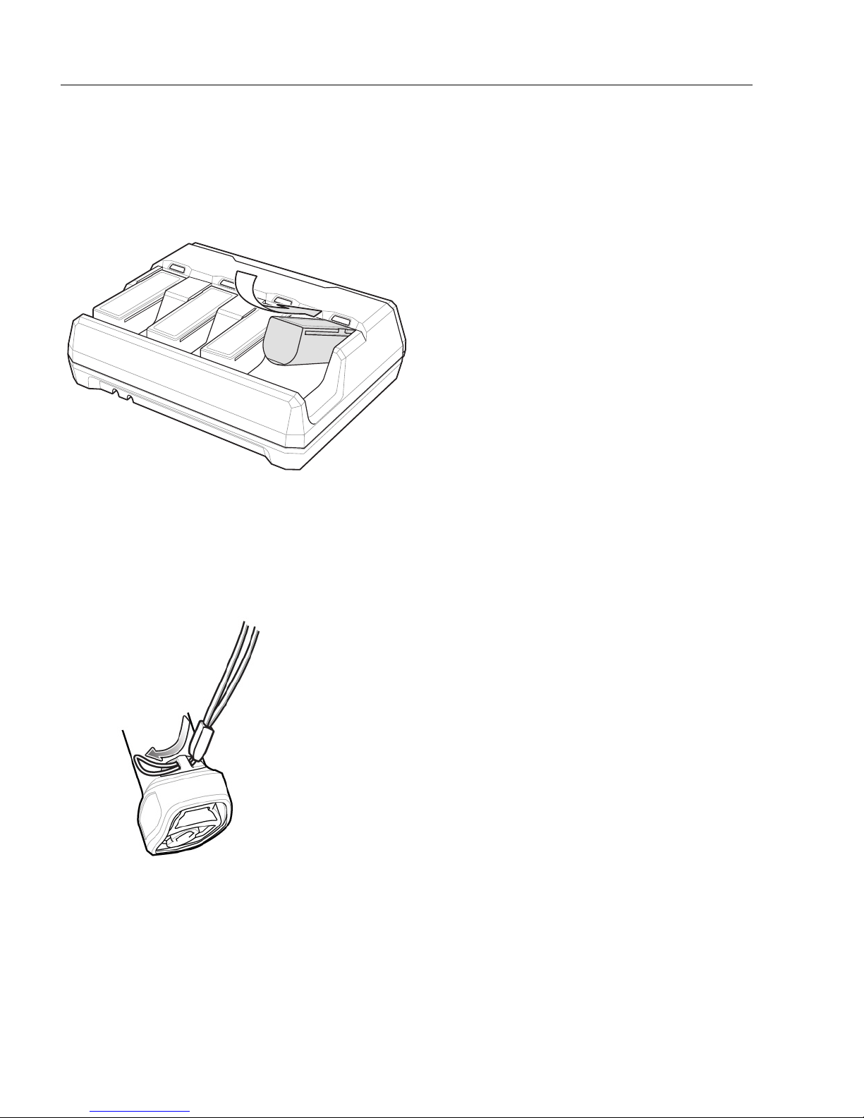
Inserting
Batteries
Insert Lanyard Loop
Inserting Batteries
To insert batteries in the battery charger, angle the battery with the contacts facing up and
slide the contact side of the battery under the LED indicator ledge as shown below. Push
down on the label surface of the battery until it clicks in place, engaging the contacts in the
battery charger.
Lanyard
Do not attach the tool balancer to the lanyard slot at the bottom of the device.
To install the optional lanyard:
1. Insert the loop on the lanyard into the slot at the bottom of the device handle.
1-12 HS-360X Handheld DPM Scanner User Manual
Page 23
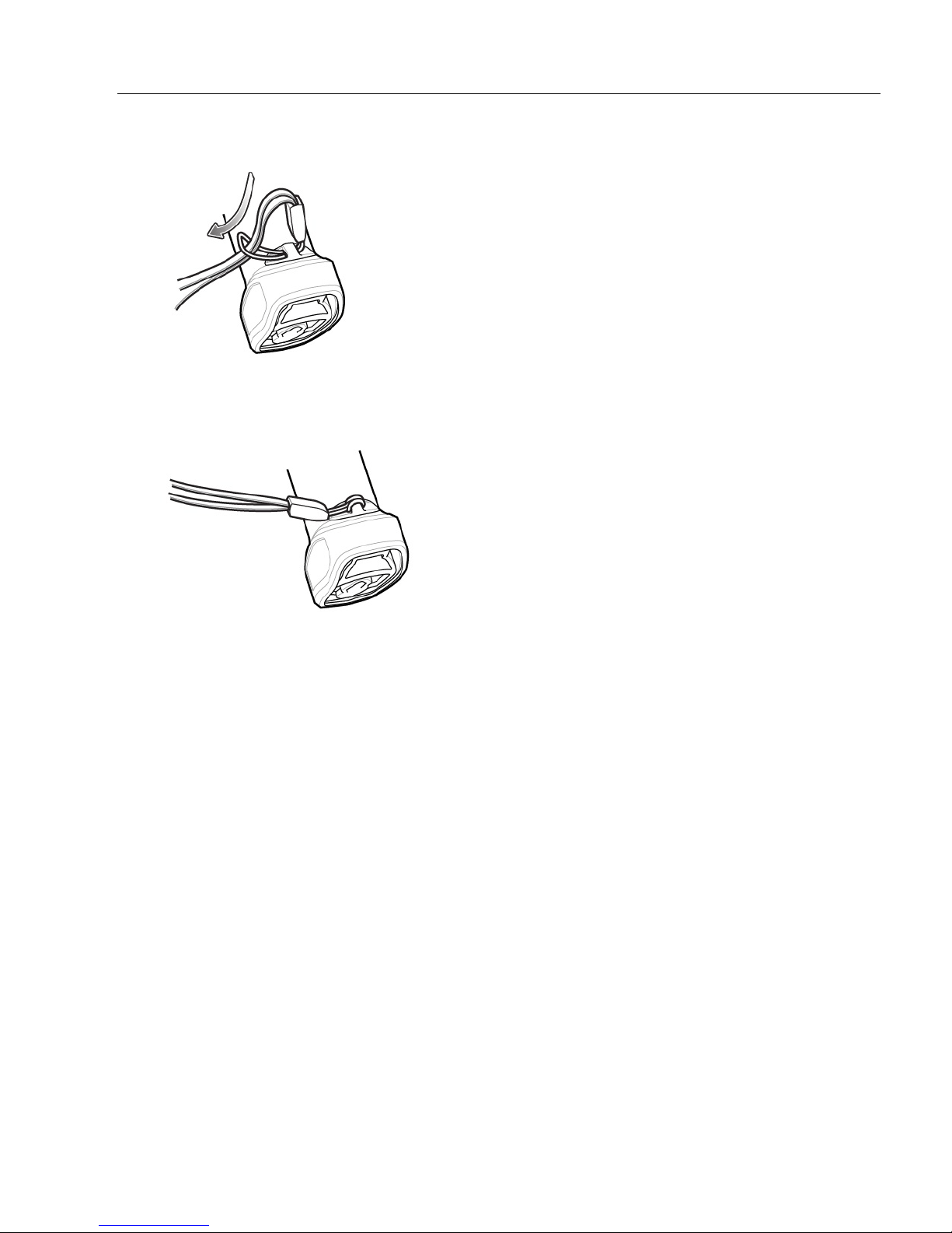
2. Thread the upper portion of the lanyard into the loop.
Thread the Loop
Insert Loop into Tether Point
3. Pull the clip through the loop over the tether point and tighten into place.
Quick Start
HS-360X Accessories
The scanner ships with a battery and the HS-360X Wireless Scanner Quick Start Guide.
The following required accessories must be ordered:
• Interface cable for the appropriate interface.
• Universal power supply, if the interface requires this.
HS-360X Handheld DPM Scanner User Manual 1-13
Page 24
HS-360X Wired Handheld DPM Scanner
Beeper
LEDs
Trigger
Scan Window
HS-360X Wired Handheld DPM Scanner
Parts
1-14 HS-360X Handheld DPM Scanner User Manual
Page 25
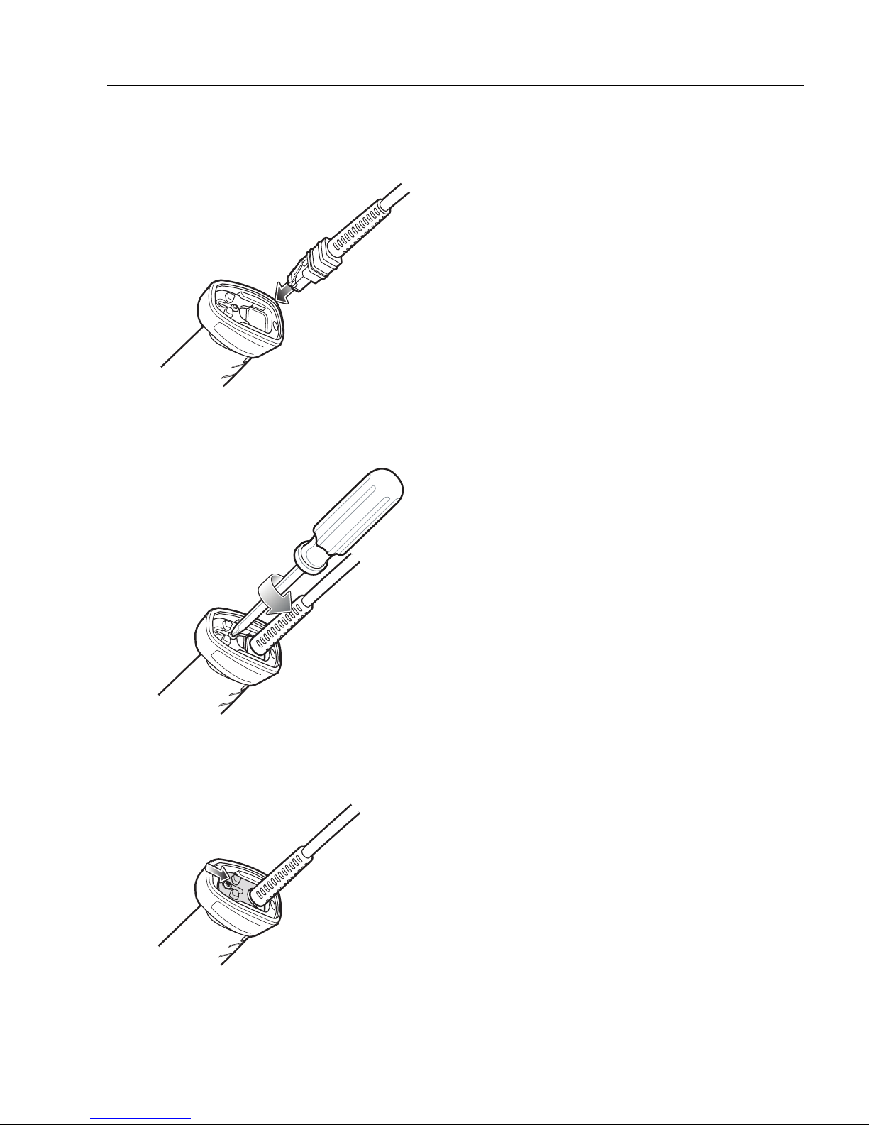
Installing the HS-360X Interface Cable
Inserting Cable into HS-360X
Important: Be sure the interface cable is pushed
all the way into the connector before closing and
fastening the lock plate.
Loosening HS-360X Lock Plate Screw
Sliding Lock Plate into Locked Position
1. Insert cable fully so that the connector is flush with the scanner surface.
2. Loosen metal lock plate screw using a PH1 driver.
Quick Start
3. Slide lock plate to fully locked position.
HS-360X Handheld DPM Scanner User Manual 1-15
Page 26
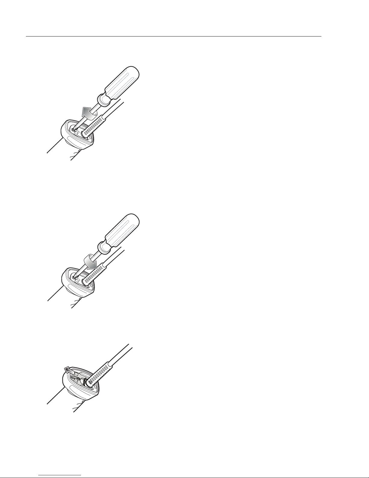
HS-360X Wired Handheld DPM Scanner
Tightening Lock Plate
Loosening Lock Plate
Sliding Lock Plate into Unlocked Position
4. Tighten lock plate screw using a PH1 driver (recommended Torque: 5 in-lbs).
Removing the HS-360X Interface Cable
1. Loosen lock plate screw using a PH1 driver.
2. Slide lock plate to fully unlocked position.
1-16 HS-360X Handheld DPM Scanner User Manual
Page 27
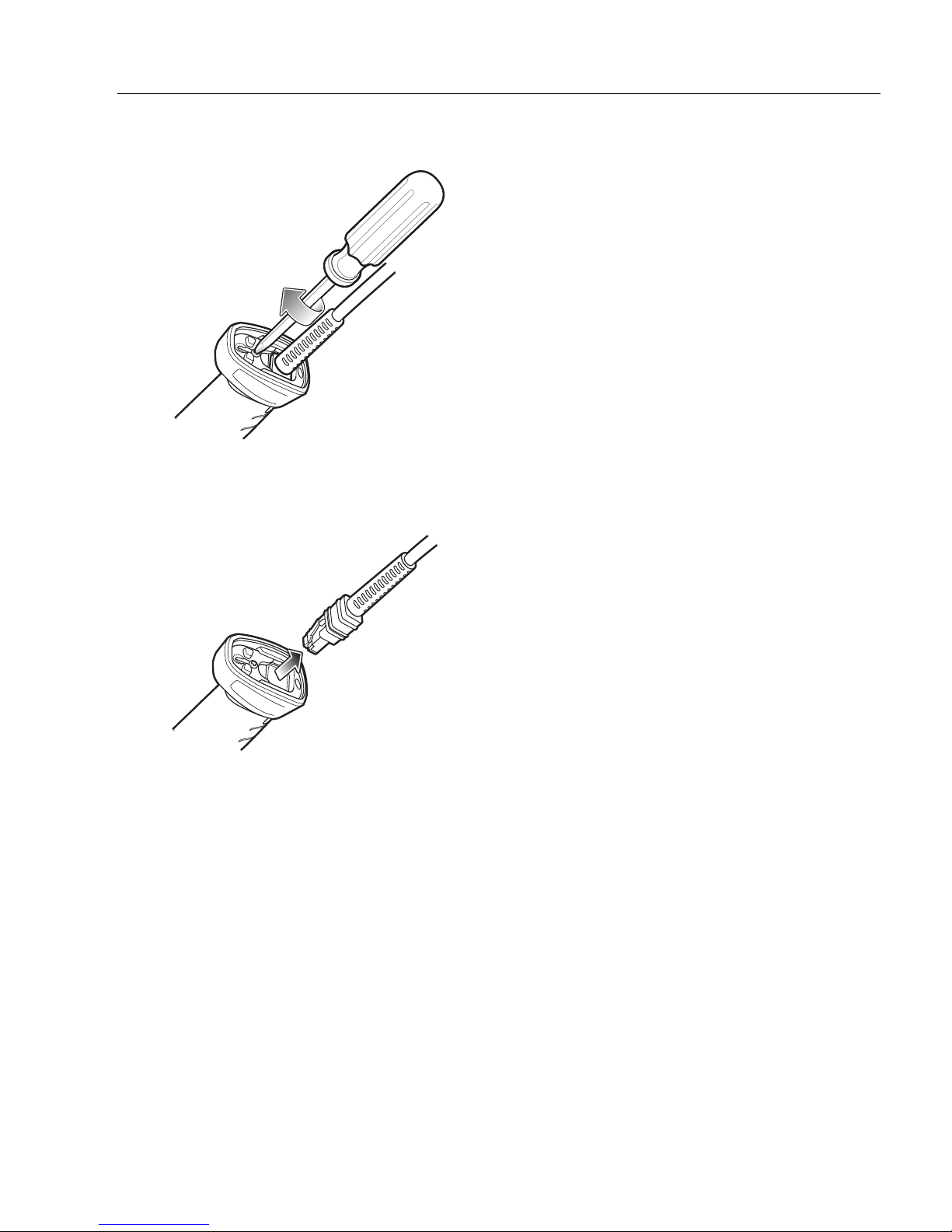
3. Tighten lock plate to fully unlocked position.
Tightening Lock Plate into Unlocked Position
Removing Cable from HS-360X
4. Remove cable.
Quick Start
HS-360X Handheld DPM Scanner User Manual 1-17
Page 28

HS-360X Wired Handheld DPM Scanner
Connecting Power to the HS-360X (If Required)
If the host does not provide power to the scanner, connect an external power supply.
1. Plug the power supply into the power jack on the interface cable.
2. Plug the other end of the power supply into an AC outlet.
Configuring the HS-360X Scanner
Use the configuration symbols included in this manual, or WebLinkPC software, to configure
the scanner.
HS-360X Accessories
The scanner ships with the HS-360X Wired Scanner Quick Start Guide. The following required
accessories
• Interface cable for the appropriate interface.
• Universal power supply, if the interface requires this.
• HS-360X Stand for hands-free operation of the scanner.
must be ordered:
1-18 HS-360X Handheld DPM Scanner User Manual
Page 29

2 Data Capture
This section provides beeper and LED definitions, techniques involved in scanning barcodes,
general instructions and tips about scanning, and decode ranges.
HS-360X Handheld DPM Scanner User Manual 2-1
Page 30

HS-360X Wireless Scanner Beeper and LED
HS-360X Wireless Scanner Beeper and LED
The scanner issues different beep sequences/patterns and an LED display to indicate status.
Radio and Beeper LED Definitions
In addition to the System/Decode LEDs, the HS-360X Wireless Scanner has a Radio and
Battery LED gauge.
The Radio and Battery LED gauge is always active when inserted in the cradle. After the
scanner is removed from the cradle, it is active for four seconds.
After the trigger is held for three seconds the Radio and Battery LED gauge remain active for
four seconds after trigger release.
See the following page for a complete list of definitions.
2-2 HS-360X Handheld DPM Scanner User Manual
Page 31

Data Capture
HS-360X Wireless Scanner Beeper and LED Definitions
Event Beeper Sequence LED
Standard Use
Power up. Low/medium/high beeps Green
Scanning
Presentation Mode on. None Green solid
Presentation Mode off. None No LED; green LED is turned off
A barcode was successfully
decoded.
Parity error. Low/low/low/extra low beeps Red
A transmission error was detected
in a scanned symbol. The data is
ignored. This occurs if a unit is not
properly configured. Check option
setting.
Conversion or format error. Five long low beeps Red
A <BEL> character is received
over RS-232.
Wireless Operation
Out of batch storage memory,
unable to store new barcode.
Radio Indications
Scanner inserted into a cradle
(may be disabled).
Medium beep (or as configured) Green flash
Four long low beeps Red
High None
Low, high, low, high Red
Low
System LED: None
Radio LED: None
System LED: Green
Bluetooth connection established. Low, high
Bluetooth disconnection event. High, low
Bluetooth Page timeout; remote
device is out of range/not powered.
Bluetooth connection attempt was
rejected by remote device.
Bluetooth attempting reconnection. None
Bluetooth attempting reconnection
(default is disable).
Paging state indication Six high System LED: Blue (fast, fast, slow)
HS-360X Handheld DPM Scanner User Manual 2-3
Long low, long high
Long low, long high, long low, long
high
Five high
Radio LED: Green (Stays on after
trigger hold for 3 seconds)
System LED: Red
Radio LED: Red (Stays on at
trigger pull)
System LED: Red
Radio LED: Red (Stays on at
trigger pull)
System LED: None
Radio LED: Red (Stays on at
trigger pull)
System LED: None
Radio LED: Red blinking
System LED: None
Radio LED: Red blinking
Page 32

HS-360X Wireless Scanner Beeper and LED
Event Beeper Sequence LED
Battery Indications
Low battery indication (on trigger
release)
Battery LED status
Battery end of life
Parameter Programming
Input error, incorrect barcode or
Cancel scanned, wrong entry,
incorrect barcode programming
sequence; remain in program
mode.
Keyboard parameter selected.
Enter value using barcode keypad.
Successful program exit with
change in the parameter setting.
Cancel rule entry. Rule entry mode
exited because of an error or the
user asked to exit rule entry.
Host-Specific: USB-Only
Scanner has not completed
initialization. Wait several seconds
and scan again.
Host-Specific: RS-232-Only
RS-232 receive error. High/high/high/low beeps Red
A <BEL> character is received
when Beep on <BEL> is enabled
(Point-to-Point mode only).
Four short high beeps Red (stays on)
99-51% Green
21-50% Amber
0-20% Red
99-51% Green/red alternating
21-50% Amber/red alternating
0-20% Red blinking
Long low/long high beeps Red
High/low beeps Green
High/low/high/low beeps Green
Long low/long high/long low beeps
Four high beeps None
High beep None
Green
(turns off blinking)
2-4 HS-360X Handheld DPM Scanner User Manual
Page 33

Cradle LED Definitions
Event LED
Standard Use
Power Up Green (stays on)
Radio Indications
Bluetooth connection established
Page button Blue
Battery Indications
Pre-charging
Charging Amber blinking
Fully charged Green (stays on)
Charging Error Amber fast blinking
Battery End of Life Indications
Charging Red blinking
Fully charged Red (stays on)
Charging error Red fast blinking
Maintenance Indications
Enter boot loader Red (stays on)
Firmware installation Red blinking
Green (off then on)
Amber (stays on)
Data Capture
HS-360X Handheld DPM Scanner User Manual 2-5
Page 34

HS-360X Wireless Scanner Beeper and LED
Four-Slot Battery Charger Definitions
Event LED
Standard Use
Power Up
Idle
Battery Indications
Pre-charging Amber (stays on)
Charging
Fully charged
Charging error Amber fast blinking
Battery End of Life Indications
Charging Red blinking
Fully charged Red (stays on)
Charging error Red fast blinking
Maintenance Indications
Enter bootloader Red (stays on; all four LEDs)
Firmware installation Red blinking (all four LEDs)
Red, amber, green, off (all four LEDs)
Off
Amber blinking
Green (stays on)
2-6 HS-360X Handheld DPM Scanner User Manual
Page 35

Data Capture
HS-360X Beeper and LED Definitions
In addition to beep sequences, the scanner uses a two-color LED to indicate status.
Event Beeper Sequence LED Indicator
Standard Use
Power up. Low, Medium, High beeps Green
Decode a barcode.
Hands-free Mode
(Presentation Mode On).
Handheld Mode
(Presentation Mode Off).
Transmission error.
Conversion or format error.
RS-232 receive error (Parity Error).
A <BEL> character is received
over RS-232.
Parameter Programming
Input error: Incorrect barcode,
programming sequence, or Cancel
scanned.
Number expected. Enter value
using numeric barcodes.
Successful program exit with
change in parameter setting.
Maintenance Indications
Enter Bootloader High, High beeps Red (stays on)
Firmware Installation None Red Blinking
(as configured) Green
None Green (stays on)
None Green (stays off)
4 Low beeps Red
5 Low beeps Red
Low, Low, Low, Extra-Low beeps Red
High beep None
Low, High beeps Red
High, Low beeps Green
High, Low, High, Low beeps Green
HS-360X Handheld DPM Scanner User Manual 2-7
Page 36

HS-360X Scanning
HS-360X Scanning a Data Matrix
Symbol in Handheld Mode
HS-360X Scanning
1. Aim the scanner at a barcode and pull the trigger to decode. The aiming laser’s red
dot should fall roughly in the center of the symbol as shown in the image below.
2. Pull the trigger until the scanner beeps, indicating the barcode is successfully decoded.
2-8 HS-360X Handheld DPM Scanner User Manual
Page 37

Data Capture
Scanner Cup
Scanner Cup
Angle Adjustment
HS-360X Stand
Height Adjustment
HS-360X Wired Scanner in Hands-Free Mode
HS-360X Wired Scanner Hands-Free Mode
The HS-360X scanner is in Hands-free (presentation) mode when it is placed in the HS-360X
Stand. In this mode, the scanner operates in continuous (constant-on) mode, where it
automatically decodes a barcode presented in its field of view.
When the scanner is not used for a user-definable period of time, it enters a low power mode
in which the LEDs are turned off or illumination blinks at a low duty cycle until the scanner
detects an image change (e.g. motion).
Scanning in Hands-Free (Presentation) Mode
The optional stand adds greater flexibility to HS-360X scanning operation. When the scanner
is seated in the scanner cup, the scanner’s built-in sensor places the scanner in
(presentation) mode. When the scanner is removed from the stand, it automatically
its programmed handheld triggered mode.
To operate the scanner in the HS-360X Stand:
1. Connect the scanner to the host (see the appropriate host chapter for informatio
host connections).
hands-free
switches to
n on
2. Insert the scanner in the HS-360X Stand by placing the front of the scanner into th
scanner cup.
3. Use the HS-360X Stand’s adjustment knobs to adjust the height and angle of the scanner.
4. Center the symbol in the aiming pattern.
5. Upon successful decode, the scanner beeps and the LED turns green.
HS-360X Handheld DPM Scanner User Manual 2-9
e
Page 38

HS-360X Scanning
HS-360X Scanner
Aiming Pattern
Aiming with the HS-360X
When scanning, the HS-360X projects a red laser aiming dot which allows you to position
the symbol within the scanner’s field of view.
The scanner beeps to indicate that it successfully decoded the symbol.
HS-360X Decode Ranges
HS-360X
Barcode Type Symbol Density
Code 39 3.0 mil 0.2 in / 0.5 cm 2.8 in / 7.1 cm
5.0 mil 0.2 in / 0.5 cm 2.8 in / 7.1 cm
PDF417
6.6 mil * 0.2 in / 0.5 cm 3.2 in. / 8.1 cm
5.0 mil 0.4 in / 1.0 cm 2.5 in / 6.3 cm
Data Matrix
10.0 mil 0.0 in / 0.0 cm 3.4 in / 8.6 cm
5.0 mil 0.4 in / 1.0 cm 2.5 in / 6.3 cm
QR
10.0 mil 0.0 in / 0.0 cm 3.4 in / 8.6 cm
100% UPC 13.0 mil * 1.0 in / 2.5 cm * 5.8 in / 14.7 cm
* Field of view/barcode width limited. Decode ranges measured with DPM Mode Off, photographic
paper barcodes and under 30fcd ambient light conditions.
Typical Working Ranges
Near Far
2-10 HS-360X Handheld DPM Scanner User Manual
Page 39

3 Maintenance and
Technical Specifications
This section describes recommended scanner maintenance, troubleshooting, technical
specifications, and pin assignments.
.
HS-360X Handheld DPM Scanner User Manual 3-1
Page 40

Maintenance
Maintenance
Known Harmful Ingredients
The following chemicals are known to damage the plastics on Omron Microscan products
and should not come in contact with the device:
•Acetone
• Ammonia solutions
• Aqueous or alcoholic alkaline solutions
• Aromatic and chlorinated hydrocarbons
• Benzene
•Bleach
• Carbolic acid
• Compounds of amines or ammonia
• Ethanolamine
•Ethers
• Ketones
•TB-lysoform
• Toluene
• Trichloroethylene
Approved Cleaning Agents
The following cleaning agents are approved for cleaning Omron Microscan products:
• Pre-moistened wipes
• Isopropyl alcohol 70%
3-2 HS-360X Handheld DPM Scanner User Manual
Page 41

Maintenance and Technical Specifications
Tolerable Industrial Fluids and Chemicals
Not all fluid variants and brands have been tested.
The following industrial fluids and chemicals were evaluated and deemed tolerable for the
HS-360X:
• Motor/Engine Oil
• Automatic Transmission Fluid (ATF)
• Continuously Variable Transmission Fluid (CVT)
• Industrial De-Greaser (Engine Brite Heavy Duty)
• Brake Fluid (DOT4)
If the scanner comes in contact with the above fluids and chemicals frequently, Omron
Microscan recommended that you clean the outside of the scanner daily using the
approved cleaning agents listed on the previous page.
Cleaning the Scanner
Routinely cleaning the exit window is required. A dirty window may affect scanning accuracy.
Do not allow any abrasive material to touch the window.
To clean the scanner:
1. Dampen a soft cloth with one of the approved cleaning agents listed above or use
pre-moistened wipes.
2. Gently wipe all surfaces, including the front, back, sides, top and bottom. Never
apply liquid directly to the scanner. Be careful not to let liquid pool around the scanner
window, trigger, cable connector or any other area on the device.
3.
Be sure to clean the trigger and in between the trigger and the housing (use a cotton-tipped
applicator to reach tight or inaccessible areas).
4. Do not spray water or other cleaning liquids directly into the exit window.
5. Wipe the scanner exit window with a lens tissue or other material suitable for cleaning
optical material such as eyeglasses.
6. Immediately dry the scanner window after cleaning with a soft non-abrasive cloth to
prevent streaking.
7. Allow the unit to air dry before use.
8. Scanner connectors:
a. Dip the cotton portion of a cotton-tipped applicator in isopropyl alcohol.
b. Rub the cotton portion of the cotton-tipped applicator back-and-forth across the
connector on the Omron Microscan scanner at least 3 times. Do not leave any
cotton residue on the connector.
c. Use the cotton-tipped applicator dipped in alcohol to remove any grease and dirt
near the connector area.
d. Use a dry cotton tipped applicator and rub the cotton portion of the cotton-tipped
applicator back-and-forth across the connectors at least 3 times. Do not leave any
cotton residue on the connectors.
HS-360X Handheld DPM Scanner User Manual 3-3
Page 42

Troubleshooting
Troubleshooting
Problem Possible Causes Possible Solutions
If the configuration requires a
The aiming pattern does not
appear when pressing the trigger.
Scanner emits aiming pattern, but
does not decode the barcode.
Scanner decodes barcode, but
does not transmit the data to the
host.
No power to the scanner.
Incorrect host interface cable is
used.
Interface/power cables are loose. Re-connect cables.
Aiming pattern is disabled. Enable the aiming pattern.
Scanner is not programmed for the
correct barcode type.
Barcode symbol is unreadable.
The symbol is not completely
inside aiming pattern.
Distance between scanner and
barcode is incorrect.
Scanner is not programmed for the
correct host type.
Interface cable is loose. Re-connect the cable.
Cradle is not programmed for the
correct host type.
Scanner is not paired to host
connected interface.
Cradle has lost connection to the
host.
If the scanner emits 4 long low
beeps, a transmission error
occurred.
This occurs if a unit is not properly
configured or connected to the
wrong host type.
If the scanner emits 5 low beeps, a
conversion or format error
occurred.
If the scanner emits low/high/low
beeps, it detected an invalid
scanner rule.
power supply, reconnect the power
supply.
Connect the correct host interface
cable.
Program the scanner to read that
type of barcode.
Scan test symbols of the same
barcode type to determine if the
barcode is defaced.
Move the symbol completely within
the aiming pattern.
Move the symbol completely within
the field of view (AIM pattern does
NOT define FOV)
Move the scanner closer to or
further from the barcode.
Scan the appropriate host type
programming symbol. See the
chapter corresponding to the host
type.
Check scanner host parameters or
edit options.
Pair scanner to the cradle by
scanning the PAIR symbol on the
cradle.
In this exact order: disconnect
power supply; disconnect host
cable; wait three seconds;
reconnect host cable; reconnect
power supply; reestablish pairing.
Set the scanner's communication
parameters to match the host's
setting.
Configure the scanner's
conversion parameters properly.
Program the correct scanner rules.
3-4 HS-360X Handheld DPM Scanner User Manual
Page 43

Maintenance and Technical Specifications
Problem Possible Causes Possible Solutions
Scan the appropriate host type
programming symbol.
For RS-232, set the scanner's
Host displays scanned data
incorrectly.
Scanner emits short low/short
medium/short high beep sequence
(power-up beep sequence) more
than once.
Scanner emits 4 short high beeps
during decode attempt.
Scanner emits Low/low/low/extra
low beeps when not in use.
Scanner emits low/high beeps
during programming.
Scanner emits low/high/low/high
beeps during programming.
Scanner emits a power-up beep
after changing USB host type.
Scanner emits one high beep when
not in use.
Scanner emits frequent beeps.
Scanner emits five long low beeps
after a barcode is decoded.
Scanner is not programmed to
work with the host.
The USB bus may put the scanner
in a state where power to the
scanner is cycled on and off more
than once.
Scanner has not completed USB
initialization.
RS-232 receive error.
Input error, incorrect barcode or
Cancel barcode was scanned.
Out of host parameter storage
space.
The USB bus re-established power
to the scanner.
In RS-232 mode, a <BEL>
character was received and Beep
on <BEL> option is enabled.
No power to the scanner.
Incorrect host interface cable is
used.
Interface/power cables are loose.
Conversion or format error was
detected.
The scanner’s conversion
parameters are not properly
configured.
Conversion or format error was
detected.
A barcode was scanned with
characters that can't be sent for
that host.
communication parameters to
match the host's settings.
Program the proper editing options
(e.g., UPC-E to UPC-A
Conversion).
Normal during host reset.
Wait several seconds and scan
again.
Normal during host reset.
Otherwise, set the scanner's RS-232
parity to match the host setting.
Scan the correct numeric barcodes
within range for the parameter
programmed.
Change storage preference.
Normal when changing USB host
type.
Normal when Beep on <BEL> is
enabled and the scanner is in RS-232
mode.
Check the system power. If the
configuration requires a power
supply, re-connect the power
supply.
Verify that the correct host
interface cable is used. If not,
connect the correct host interface
cable.
Check for loose cable connections
and re-connect cables.
Ensure the scanner’s conversion
parameters are properly
configured.
Change the barcode, or change to a
host that can support the barcode.
Note: If the scanner still experiences problems after performing these checks, contact
customer support at www.microscan.com.
HS-360X Handheld DPM Scanner User Manual 3-5
Page 44

Troubleshooting
Report Software Version
Report Software Version Barcode
When contacting support, a support representative may ask you to scan the programming
symbol below to determine the version of software installed in the scanner.
3-6 HS-360X Handheld DPM Scanner User Manual
Page 45

Maintenance and Technical Specifications
Technical Specifications
HS-360X Technical Specifications
Item Description
Physical Characteristics
HS-360X Wireless Scanner Dimensions
HS-360X Wired Scanner Dimensions
HS-360X Wireless Scanner Weight
(with Battery)
HS-360X Wired Scanner Weight
(without Cable)
Power 5 VDC +/- 10% @ 360 mA (RMS typical)
Color Black, red
Performance Characteristics
Light Source
Field of View (Horizontal x Vertical) Nominal 31º (H) x 23º (V)
Roll 0 - 360º
Pitch +/- 60º
Skew +/- 60º
Scans Per Charge Up to 100,000
Symbologies
1D
2D
Postal
Typical Working Distance See HS-360X Decode Ranges.
Interfaces Supported
7.3 in. H x 3.0 in. W x 5.6 in. D
(18.5 cm H x 7.7 cm W x 14.3 cm D)
7.3 in. H x 3.0 in. W x 5.2 in. D
(18.5 cm H x 7.7 cm W x 13.2 cm D)
Approximately 14.18 oz./402 g
Approximately 10.72 oz./304 g
Aiming pattern: 655 nm Laser / Illumination: Warm
white and red 634nm LEDs
UPC/EAN, UPC/EAN with supplementals, Bookland
EAN, ISSN, UCC Coupon Extended Code, Code
128, GS1-128, ISBT 128, ISBT Concatenation, Code
39, Code 39 Full ASCII, Trioptic Code 39, Code 32,
Code 93, Code 11, Interleaved 2 of 5, Discrete 2 of 5,
Codabar, MSI, Chinese 2 of 5, Matrix 2 of 5, Korean
3 of 5, GS1 DataBar variants
PDF417, MicroPDF417, Composite Codes, TLC-39,
Data Matrix, Maxicode,
Han Xin, GS1-QR, GS1-DM
US Postnet, US Planet, UK Postal, Japan Post,
Australia Post, Royal Mail 4 State Customer, KIX
Code (Dutch), UPU 4 State Postal FICS (Post US4),
USPS 4 State Postal (Post US3)
USB, RS-232
The scanner supports the following protocols over
USB: HID Keyboard (default mode), SNAPI, COM
Port Emulation, USB CDC
QR Code, MicroQR, Aztec,
HS-360X Handheld DPM Scanner User Manual 3-7
Page 46

Technical Specifications
Item Description
Code 39: 3 mil
Minimum Resolution
User Environment
HS-360X Wireless Scanner Operating Temperature - 4° F to 122° F (-20° C to 50° C)
HS-360X Wired Scanner Operating Temperature - 22° F to 122° F (-30° C to 50° C)
Storage Temperature - 40º F to 158º F (-40º C to 70º C)
Humidity 5% to 95% RH, non-condensing
ESD 20 kV air discharge; 10 kV contact discharge
HS-360X Wireless Scanner Drop Specifications
HS-360X Wired Scanner Drop Specifications
Environmental Sealing IP65 and IP67
Ambient Light Immunity
Accessories
HS-360X Wired Scanner Hands-Free Option HS-360X Stand
Power Supplies
PDF417: 4 mil
Data Matrix: 4 mil
Withstands multiple 8 ft. / 2.4 m drops to concrete at
room temperature.
Withstands multiple 6.5 ft. / 2.0 m drops to concrete
at -30° C to 50° C.
0 to 10,037 Foot-Candles
0 to 108,000 Lux
Power supplies are available for applications that do
not supply power over the host cable.
3-8 HS-360X Handheld DPM Scanner User Manual
Page 47

Maintenance and Technical Specifications
Cradle Technical Specifications
Item Description
Power Requirements for Host-Powered Min 4.5 - Max 5.5
Power Requirements for External Power Supply Min 11.4 - Max 12.6
Typical Current Draw when Not Charging 80mA @ 5V; 30mA @ 12V
Typical Current Draw in Full Charging Mode
Typical Current Draw in Safe Charging Mode 400mA @ 5V; 200mA @ 12V
Interfaces Supported USB, RS-232
Operating Temperature -4° to 122° F (-20° to 50° C)
Storage Temperature -40° to 158° F (-40° to 70° C)
Charging Temperature
Humidity 5% to 95% (non-condensing)
ESD
Weight 13.7 oz (390 grams)
Dimensions
Radio
Electrical Safety
Input Transient Protection IEC 1000-4-(2,3,4,5,6,11)
EMI
1200mA @ 5V (BC 1.2), 475mA (non-BC1.2);
700mA @ 12V
32° to 104° F (0° to 40° C) nominal, 41° to 95° F (5°
to 35° C) ideal
25 kV air discharge
10 kV contact discharge
W 9.98 x L 22.94 x H 8.26 cm (W 99.8 x L 229.4 x H
82.6 mm)
Bluetooth, Up to 100 meters/300 ft. in open air
range/environment
Serial Port & HID Profiles
2.402 to 2.480 GHz Adaptive Frequency Hopping
(co-existence with 802.11 wireless networks)
3Mbit/s (2.1Mbit/s) for Classic Bluetooth
1Mbit/s (0.27Mbit/s) for Low Energy
Certified Pending to UL1950, CSA C22.2 No.950.
EN60950/IC950
FCC Part 15 Class B, ICES-003 Class B European
Union EMC Directive,
Australian SMA, Taiwan EMC, Japan VCCI/MITI/
Dentori
HS-360X Handheld DPM Scanner User Manual 3-9
Page 48

HS-360X Wired Scanner Signal Descriptions
Cable Interface Port
Pin 10
Pin 1
Interface Cable
Modular Connector
Base of Scanner Handle
HS-360X Wired Scanner Cable Pinouts
HS-360X Wired Scanner Signal Descriptions
The signal descriptions below apply to the connectors on the HS-360X Wired Scanner and
are for reference only.
Pin RS-232 USB
1 Cable ID Cable ID
2 Power (+5V) Power (+5V)
3 Ground Ground
4 TxD Reserved
5 RxD D +
6 RTS Reserved
7 CTS D -
8 Reserved Reserved
9 Reserved Reserved
10 Power (+12V) Power (+12V)
3-10 HS-360X Handheld DPM Scanner User Manual
Page 49

4 Radio Communications
This section provides information about the modes of operation and features available for
wireless communication between HS-360X Wireless Scanners, cradles, and hosts. This
section also includes scanner configuration parameters.
HS-360X Handheld DPM Scanner User Manual 4-1
Page 50

HS-360X Wireless Scanner Radio Communications
HS-360X Wireless Scanner Radio Communications
The scanner ships with the settings shown in the Radio Communications Parameter
Defaults. If the default values suit requirements, programming is not necessary.
To set feature values, scan a single programming symbol or a short sequence of programming
symbols. The settings are stored in non-volatile memory and are preserved even when the
scanner is powered down.
If not using a USB cable with the cradle, select a host type (see each host chapter for specific
host information) after the power-up beep. This is only necessary upon the first power-up
when connected to a new host.
Scanning Sequence Examples
In most cases, scan one programming symbol to set a specific parameter value.
Errors While Scanning
Unless otherwise specified, to correct an error during a scanning sequence, just re-scan the
correct parameter.
4-2 HS-360X Handheld DPM Scanner User Manual
Page 51

Radio Communications
Radio Communications Parameter Defaults
The table below lists the defaults for radio communication parameters. If you wish to change
any option, scan the appropriate programming symbol(s) provided in the Radio Communications
Parameters section.
See
Appendix A — Standard Default Parameters
and default parameters.
In this guide, the parameter numbers listed are the same as the attribute numbers for these
parameters.
See Appendix B — Country Codes for Country Keyboard Types (Country Codes).
for all user preferences, hosts, symbologies,
Parameter Parameter Number
Radio Communications Host
Types
BT Friendly Name 607 n/a
Discoverable Mode 610 General
Wi-Fi Friendly Mode 1299 Disable
Wi-Fi Friendly Channel Exclusion 1297 Use All Channels
Radio Output Power 1324 High
Link Supervision Timeout 1698 5 Seconds
Bluetooth Radio State 1354 On
Bluetooth HID - Wait for
Connection
HID Features for Apple iOS 1114 Disable
HID Keyboard Keystroke Delay N/A No Delay (0 msec)
CAPS Lock Override N/A Disable
Ignore Unknown Characters N/A
Emulate Keypad N/A Enable
Fast HID Keyboard 1361 Enable
Quick Keypad Emulation 1362 Enable
Keyboard FN1 Substitution N/A Disable
Function Key Mapping N/A Disable
Simulated Caps Lock N/A Disable
Convert Case N/A No Case Conversion
Reconnect Attempt Beep
Feedback
Reconnect Attempt Interval 558 30 Seconds
Auto-reconnect 604 Auto-reconnect Immediately
Beep on Insertion 288 Enable
1. Parameter number decimal values are used for programming via RSM commands.
383 Cradle Host
1714 Disable
559 Disable
1
Default
Send Barcodes with Unknown
Characters
HS-360X Handheld DPM Scanner User Manual 4-3
Page 52

Radio Communications Parameter Defaults
Parameter Parameter Number
1
Default
Beep on <BEL> 150 Enable
Modes of Operation
(Point-to-Point/Multipoint-to-Point)
Parameter Broadcast (Cradle Host
Only)
538 Point-to-Point
148 Enable
Pairing Modes 542 Unlocked
Pairing Methods 545 Enable
Toggle Pairing 1322 Disable
Connection Maintenance Interval 5002 15 Minutes
Batch Mode 544 Normal (Do Not Batch Data)
Persistent Batch Storage 1399 Disable
Page Button 746 Enable
Page Options
Page Mode
Page State Timeout
Classic and/or Low Energy
Bluetooth
1364
1365
Page Simple
1355 Classic and Low Energy
PIN Code (Set and Store) 552 12345
Variable Pin Code 608
Static
(Default PIN code is 12345)
Bluetooth Security Levels 1393 Low
1. Parameter number decimal values are used for programming via RSM commands.
4-4 HS-360X Handheld DPM Scanner User Manual
Page 53

Radio Communications
Wireless Beeper Definitions
When the scanner decodes the pairing symbol it issues various beep sequences indicating
successful or unsuccessful operations.
Radio Communications Host Types
Parameter # 383
To set up the scanner for communication with a cradle, or to use standard Bluetooth profiles,
scan the appropriate host type programming symbol below.
Classic Bluetooth vs. Low Energy Bluetooth
Bluetooth Low Energy (LE) Bluetooth has a better Wi-Fi coexistence, as advertising and
connection is done outside of the Wi-Fi channels 1, 6, and 11 (2402, 2426, 2480 MHz). Due
to its lower data rate, Bluetooth Low Energy is up to seven times slower than Classic Bluetooth
(0.27 Mbps versus 0.7-2.1 Mbps). Data intensive activities such as firmware updates, can
take significantly longer over Bluetooth Low Energy.
Cradle
Select this host type when connecting a scanner to a communication cradle.
The scanner automatically tries to reconnect to a remote device when a disconnection
occurs that is due to the radio losing communication.
To establish a connection (for initial setup only):
1. Scan the Cradle-Classic Bluetooth or Cradle-Low Energy programming symbol.
2. Scan the pairing symbol on the cradle or place the scanner in the crad
le-Classic
Crad
le.
HS-360X Handheld DPM Scanner User Manual 4-5
Cradle-Low Energy
Page 54

Radio Communications Host Types
Keyboard Emulation (HID)
Select this host type when connecting to a PC/tablet/phone emulating a Bluetooth keyboard.
• HID BT Classic - Enables the host and scanner to communicate using HID (Human
Interface Device) Keyboard Profile over Bluetooth Classic radio. The scanner(s) are
discoverable (Secondary mode) and also support Primary (Master) mode.
To establish a connection (initial setup only):
i. Scan the HID BT Classic programming symbol.
ii. Connect to Primary or Secondary mode.
• Primary mode - scan a pairing symbol with the MAC address of the host
device.
• Secondary mode - from the host, discover Bluetooth devices and select your
scanner from the discovered device list.
• HID BT LE (Discoverable) - Enables the host to establish a HID (Human Interface
Device) Keyboard Profile connection with the scanner over Bluetooth Low Energy radio.
The scanner is discoverable (Secondary mode).
To establish a connection (initial setup only):
i. Scan the HID BT LE (Discoverable) programming symbol.
ii. From the host, discover Bluetooth devices.
iii. Select your scanner from your discovered device list.
HID Bluetooth Classic
HID BT LE (Discoverable)
4-6 HS-360X Handheld DPM Scanner User Manual
Page 55

Serial Port Profile (SPP)
Radio Communications
Select this host type when connecting to a PC/tablet/phone using a Bluetooth serial connection.
• SPP BT Classic (Non-Discoverable) - Enables the scanner to establish a Serial Port
Profile (SPP) connection with the host over Classic Bluetooth radio. The scanner is NOT
discoverable (Primary mode).
To establish a connection (initial setup only):
i. Scan the SPP BT Classic (Non-discoverable) programming symbol.
ii. Scan a pairing symbol with the MAC address of the host device.
• SPP BT Classic (Discoverable) - Enables the host to establish a Serial Port Profile
(SPP) connection with the scanner over Classic Bluetooth radio. The scanner is discoverable
(Secondary mode).
To establish a connection (initial setup only):
i. Scan the SPP BT Classic (Discoverable) programming symbol.
ii. From the host, discover Bluetooth devices.
iii. Select your scanner from the discovered device list.
SPP BT Classic (Non-Discoverable)
SPP BT Classic (Discoverable)
HS-360X Handheld DPM Scanner User Manual 4-7
Page 56

Radio Communications Host Types
Bluetooth Technology Profile Support
With Bluetooth Technology Profile Support, the cradle is not required for wireless communication.
The scanner communicates directly to the host using Bluetooth technology. The scanner
supports the standard Bluetooth Serial Port Profile (SPP) and HID Profiles which enable the
scanner to communicate with other Bluetooth devices that support these profiles.
• SPP - the scanner connects to the PC/host via Bluetooth and performs like there is a
serial connection.
• HID - the scanner connects to the PC/host via Bluetooth and performs like a keyboard.
Primary/Secondary Set Up
The scanner can be set up as a Primary or Secondary. When the scanner is set up as a
Secondary, it is discoverable and connectible to other devices. When the scanner is set up
as a Primary, the Bluetooth address of the remote device to which a connection is requested
is required. A pairing symbol with the remote device address must be created and scanned
to attempt a connection to the remote device.
Primary
When the scanner is set up as a Primary (SPP), it initiates the radio connection to a secondary
device. Initiating the connection is done by scanning a pairing symbol for the remote device.
Secondary
When the scanner is set up as a Secondary device (SPP), the scanner accepts an incoming
connection request from a remote device. The number of scanners is dependent on the
host’s capability.
4-8 HS-360X Handheld DPM Scanner User Manual
Page 57

Radio Communications
Bluetooth-Friendly Name
Parameter # 607
You can set a meaningful name for the scanner that appears in the application during device
discovery. The default name is the scanner name followed by its serial number, e.g., HS-360X
123456789ABCDEF. Scanning Set Defaults reverts the scanner to this name; use custom
defaults to maintain the user-programmed name through a Set Defaults operation.
To set a new Bluetooth Friendly Name, scan the following programming symbol, then scan
up to 23 characters from Appendix G — Alphanumeric Keyboard.
Bluetooth Friendly Name
HS-360X Handheld DPM Scanner User Manual 4-9
Page 58

Bluetooth-Friendly Name
Discoverable Mode
Parameter # 610
Select a discoverable mode based on the device initiating discovery:
• Select General Discoverable Mode when initiating connection from a PC.
• Select Limited Discoverable Mode when initiating connection from a mobile de
e.g., iPhone), and the device does not appear in General Discoverable Mode. Note th
(
n take longer to discover the device in this mode.
it ca
The device remains in Limited Discoverable Mode for 30 seconds, and green LEDs flash
while in this mode. It is then non-discoverable. To re-active Limited Discoverable Mode,
press the trigger.
vice
* General Discoverable Mode
(0)
at
Limited Discoverable Mode
(1)
4-10 HS-360X Handheld DPM Scanner User Manual
Page 59

Radio Communications
Wi-Fi Friendly Mode
Parameter # 1299
Scanners configured for Wi-Fi friendly mode behave as follows:
• The scanner remains in sniff mode, and exits sniff mode only during firmware update.
• If any Wi-Fi channel is excluded from the hopping sequence, AFH turns off.
• Scanner (and cradle) avoid the selected Wi-Fi channels after establishing connection.
Notes
• If using this feature, configure all scanners in the area for Wi-Fi friendly mode.
• By default, no Wi-Fi channels are excluded.
• Since Bluetooth requires a minimum of 20 channels when Wi-Fi channels 1, 6, and 11
are excluded,
a smaller number of channels are cut from the hopping sequence.
• Updating Wi-Fi friendly settings before Bluetooth connection is recommended.
Scan a programming symbol below to enable or disable Wi-Fi Friendly Mode.
* Disable Wi-Fi Friendly Mode
(0)
Enable Wi-Fi Friendly Mode
(1)
HS-360X Handheld DPM Scanner User Manual 4-11
Page 60

Wi-Fi Friendly Mode
Wi-Fi Friendly Channel Exclusion
Parameter # 1297
WiFi Channel Exclusion
Select the channels to exclude:
• Exclude Wi-Fi channel 1: Bluetooth channels 0-21 are excluded from hopping sequence
(2402-2423 MHz).
• Exclude Wi-Fi channel 6: Bluetooth channels 25-46 are excluded from hopping
sequence (2427 - 2448 MHz).
• Exclude Wi-Fi channel 11: Bluetooth channels 50-71 are excluded from hopping
sequence (2452 - 2473 MHz).
•
Exclude Wi-Fi channel 1, 6 and 11
26-45 (2428 - 2447 MHz) and 51-69 (2453 - 2471 MHz) are excluded from hopping sequence.
• Exclude Wi-Fi channels 1 and 6: Bluetooth channels 0-21 (2402-2423 MHz) and 25-46
(2427 - 2448 MHz) are excluded from hopping sequence.
• Exclude Wi-Fi channels 1 and 11: Bluetooth channels 0-21 (2402-2423 MHz) and 50-71
(2452 - 2473 MHz) are excluded from hopping sequence.
•
Exclude Wi-Fi channel 6 and 11
(2452 - 2473 MHz) are excluded from hopping sequence.
: Bluetooth channels 2-19 (2404-2421 MHz),
: Bluetooth channels 25-46 (2427 - 2448 MHz) and 50-71
* Use All Channels (Standard)
(0)
Exclude Wi-Fi Channel 1
(1)
Exclude Wi-Fi Channel 6
(2)
4-12 HS-360X Handheld DPM Scanner User Manual
Page 61

Exclude Wi-Fi Channels 1, 6, and 11
(4)
Radio Communications
Exclude Wi-Fi Channel 11
(3)
Exclude Wi-Fi Channels 1 and 11
(6)
Exclude Wi-Fi Channels 1 and 6
(5)
Exclude Wi-Fi Channels 6 and 11
(7)
HS-360X Handheld DPM Scanner User Manual 4-13
Page 62

Radio Output Power
Radio Output Power
Parameter # 1324
The HS-360X Wireless Scanner uses a Class 1 Bluetooth radio. Optionally, reduce the
radio’s output power to restrict the transmission range and reduce the effect of the radio on
neighboring wireless systems.
Bluetooth stack resets on power change and the device loses connection.
Scan a programming symbol to select the desired power mode.
* High Power Setting
(0)
Medium Power Setting
(1)
Low Power Setting
(2)
4-14 HS-360X Handheld DPM Scanner User Manual
Page 63

Radio Communications
Link Supervision Timeout
Parameter # 1698
Link supervision timeout controls how quickly the scanner senses that the Bluetooth radio
lost connection to the remote device. A lower value helps prevent data loss at the edge of
the operating range while a larger value helps prevent disconnects due to the remote device
not responding in time. If you are experiencing occasional disconnects and the scanner is
able to reconnect, increase the link supervision timeout value.
.5 Seconds
5 Seconds
2 Seconds
10 Seconds
20 Seconds
HS-360X Handheld DPM Scanner User Manual 4-15
Page 64

Bluetooth Radio State
Bluetooth Radio State
Parameter # 1354
The only option to turn the radio on after it is turned off on the cradle, is through the host.
Bluetooth Radio Off
(0)
* Bluetooth Radio On
(1)
4-16 HS-360X Handheld DPM Scanner User Manual
Page 65

Radio Communications
HID Host Parameters
The scanner supports virtual keyboard emulation for the Apple iOS, and keyboard emulation
over the Bluetooth HID profile. In this mode the scanner can interact with Bluetooth enabled
hosts supporting the HID profile as a Bluetooth keyboard. Scanned data is transmitted to the
host as keystrokes.
Bluetooth HID - Wait for Connection
Parameter # 1714
This setting applies to first time connection only, when scanner connects to remote device
by scanning a paring symbol.
When disabled, the scanner issues a connection after scanning a pairing symbol. This is the
recommended setting for Android devices.
When enabled, the scanner waits for a connection request from a remote device, after scanning
a pairing symbol and initiating pairing. This is the recommended setting for Windows devices
and VC80.
* Disable
(0)
Enable
(1)
HS-360X Handheld DPM Scanner User Manual 4-17
Page 66

HID Host Parameters
HID Features for Apple iOS
Parameter # 1114
This option works with Apple iOS devices to enable the opening and closing of the iOS virtual
keyboard by double-pressing the trigger.
When this feature is enabled, the scanner may be incompatible with non-Apple iOS devices.
* Disable
(0)
Enable
(1)
4-18 HS-360X Handheld DPM Scanner User Manual
Page 67

Radio Communications
HID Keyboard Keystroke Delay
This parameter sets the delay, in milliseconds (msec), between emulated keystrokes. Scan a
programming symbol below to increase the delay when the HID host requires a slower
transmission
of data.
* No Delay (0 msec)
Long Delay (40 msec)
Medium Delay (20 msec)
HS-360X Handheld DPM Scanner User Manual 4-19
Page 68

HID Host Parameters
HID Caps Lock Override
When enabled, the case of the data is preserved regardless of the state of the caps lock key.
This setting is always enabled for the Japanese, Windows (ASCII) keyboard type and can
not be disabled.
* Do Not Override Caps Lock Key
(Disable)
Override Caps Lock Key
(Enable)
4-20 HS-360X Handheld DPM Scanner User Manual
Page 69

Radio Communications
HID Ignore Unknown Characters
This option applies only to the HID Keyboard Emulation device and IBM device. Unknown
characters are characters the host does not recognize. When Send Barcodes With
Unknown Characters is selected, all barcode data is sent except for unknown characters,
and no error beeps sound. When Do Not Send Barcodes With Unknown Characters is
selected, barcode data is sent up to the first unknown character, then the scanner issues an
error beep.
* Send Barcodes With Unknown
Characters
(Enable)
Do Not Send Barcodes With Unknown
Characters
(Disable)
HS-360X Handheld DPM Scanner User Manual 4-21
Page 70

HID Host Parameters
Emulate Keypad
When enabled, all characters are sent as ASCII sequences over the numeric keypad. For
example, ASCII A is sent as "ALT make" 0 6 5 "ALT Break".
Disable Keypad Emulation
* Enable Keypad Emulation
4-22 HS-360X Handheld DPM Scanner User Manual
Page 71

Fast HID Keyboard
Parameter # 1361
This option transmits Bluetooth HID keyboard data at a faster rate.
Fast HID Disable
(0)
Radio Communications
* Fast HID Enable
(1)
HS-360X Handheld DPM Scanner User Manual 4-23
Page 72

HID Host Parameters
Quick Keypad Emulation
Parameter # 1362
This option applies only to a HID Keyboard Emulation Device which has Emulate Keypad
enabled.
This parameter enables a quicker method of keypad emulation where ASCII sequences are
only sent for ASCII characters not found on the keyboard.
Quick Keypad Emulation Disable
(0)
* Quick Keypad Emulation Enable
(1)
4-24 HS-360X Handheld DPM Scanner User Manual
Page 73

HID Keyboard FN1 Substitution
Radio Communications
When enabled, this parameter allows replacement of any FN1 character in an EAN128 barcode
with a Key Category and value chosen by the user.
* Disable Keyboard FN1 Substitution
Enable Keyboard FN1 Substitution
HS-360X Handheld DPM Scanner User Manual 4-25
Page 74

HID Host Parameters
HID Function Key Mapping
ASCII values under 32 are normally sent as control-key sequences. When this parameter is
enabled, the keys in bold are sent in place of the standard key mapping.
Table entries that do not have a bold entry remain the same whether or not this parameter is
enabled.
* Disable Function Key Mapping
Enable Function Key Mapping
4-26 HS-360X Handheld DPM Scanner User Manual
Page 75

Radio Communications
Simulated Caps Lock
When enabled, the scanner inverts upper and lower case characters on the barcode as if the
Caps Lock state is enabled on the keyboard. This inversion is done regardless of the current
state of the keyboard Caps Lock state.
* Disable Simulated Caps Lock
Enable Simulated Caps Lock
HS-360X Handheld DPM Scanner User Manual 4-27
Page 76

HID Host Parameters
Convert Case
When enabled, the scanner converts all barcode data to the selected case.
* No Case Conversion
Convert All to Upper Case
Convert All to LowerCase
4-28 HS-360X Handheld DPM Scanner User Manual
Page 77

Radio Communications
Reconnect Attempt Beep Feedback
When in SPP Primary, Cradle Host Mode, and Bluetooth Keyboard Emulation, the scanner
automatically tries to reconnect to a remote device when a disconnection occurs that is due
to the radio losing communication. This can happen if the scanner goes out of range with the
remote device, or if the remote device powers down. The scanner tries to reconnect for the
period of time specified by the Reconnect Attempt Interval setting. During that time the
green LED continues to blink.
If the auto-reconnect process fails due to page time-outs, the scanner sounds a page timeout
beep (long low/long high) and enters low power mode. The auto-reconnect process can be
re-started by pulling the scanner trigger.
If the auto-reconnect process fails because the remote device rejects the connection
attempt, the scanner sounds a connection reject beep sequence and deletes the remote
pairing address. If this happens, a pairing
to the remote device.
If a barcode is scanned while the auto-reconnect sequence is in process, a transmission
error beep sequence sounds and the data is not transmitted to the host. After a connection
is reestablished, normal scanning operation returns.
The scanner has memory available for storing a remote Bluetooth address for each Primary
mode (SPP, Cradle). When switching between these modes, the scanner automatically tries
to reconnect to the last device it was connected to in that mode.
Switching between Bluetooth host types by scanning a host type programming symbol
causes the radio to be reset. Scanning is disabled during this time. It takes several seconds
for the scanner to re-initialize the radio at which time scanning is enabled.
symbol
must be scanned to attempt a new connection
HS-360X Handheld DPM Scanner User Manual 4-29
Page 78

Reconnect Attempt Beep Feedback
Reconnect Attempt Beep Feedback
Parameter # 559
When a scanner disconnects as it goes out of range, it immediately attempts to reconnect.
While the scanner attempts to reconnect, the green LED continues to blink. If the auto-reconnect
process fails, the scanner emits a page timeout beep (long low/long high) and stops blinking
the LED. The process can be restarted by pulling the trigger.
The Beep on Reconnect Attempt feature is disabled by default. When enabled, the scanner
emits 5 short high beeps every 5 seconds while the re-connection attempt is in progress.
Scan a programming symbol below to enable or disable Beep on Reconnect Attempt.
* Disable Beep on Reconnect Attempt
(0)
Enable Beep on Reconnect Attempt
(1)
4-30 HS-360X Handheld DPM Scanner User Manual
Page 79

Radio Communications
Reconnect Attempt Interval
Parameter # 558
When a scanner disconnects as it goes out of range, it immediately attempts to reconnect
for the default time interval of 30 seconds. This time interval can be changed to one of the
options below.
To set the Reconnect Attempt Interval, scan one of the programming symbols below.
* Attempt to Reconnect for 30 Seconds
(6)
Attempt to Reconnect for 5 Minutes
(60)
Attempt to Reconnect for 1 Minute
(12)
Attempt to Reconnect for 30 Minutes
(360)
HS-360X Handheld DPM Scanner User Manual 4-31
Page 80

Reconnect Attempt Beep Feedback
Attempt to Reconnect for 1 Hour
(720)
Attempt to Reconnect Indefinitely
(0)
4-32 HS-360X Handheld DPM Scanner User Manual
Page 81

Radio Communications
Auto-Reconnect
Parameter # 604
In Bluetooth Keyboard Emulation (HID) mode, SPP Primary, and Cradle Host Mode, select a
re-connect option for when the scanner loses its connection with a remote device:
• Auto-reconnect on Barcode Data: The scanner auto-reconnects when you scan a
barcode. With this option, a delay can occur when transmitting the first characters. The
scanner sounds a decode beep upon barcode scan, followed by a connection, a page
timeout, a rejection beep, or a transmission error beep. Select this option to optimize
battery life on the scanner and mobile device. Note that auto-reconnect does not occur
on rejection and cable unplug commands.
• Auto-reconnect Immediately: When the scanner loses connection, it attempts to
reconnect. If a page timeout occurs, the scanner attempts reconnect on a trigger pull.
Select this option if the scanner’s battery life is not an issue and you do not want a delay
to occur when the first barcode is transmitted. Note that auto-reconnect does not occur
on rejection and cable unplug commands.
• Disable Auto-reconnect: When the scanner loses connection, you must re-establish it
manually.
Auto-Reconnect on Barcode Data
(1)
Disable Auto-Reconnect
(0)
* Auto-Reconnect Immediately
(2)
HS-360X Handheld DPM Scanner User Manual 4-33
Page 82

Out-of-Range Indicator
Out-of-Range Indicator
An out-of-range indicator can be set by scanning
the time using the Reconnect Attempt Interval.
For example, with Beep on Reconnect Attempt disabled while the scanner loses radio
connection when it is taken out of range, the scanner attempts to reconnect silently during
the time interval set by scanning a Reconnect Attempt Interval.
When Beep on Reconnect Attempt is enabled, the scanner emits 5 high beeps every 5
seconds while the re-connection attempt is in progress. If the Reconnect Attempt Interval is
adjusted to a longer period of time, such as 30 minutes, the scanner emits 5 high beeps
every 5 seconds for 30 minutes providing an out-of-range indicator.
Beep On Reconnect Attempt
and extending
4-34 HS-360X Handheld DPM Scanner User Manual
Page 83

Radio Communications
Beep on Insertion
Parameter # 288
When a scanner is inserted into a cradle and detects power, it emits a short low beep. This
feature is enabled by default.
To enable or disable beeping on insertion, scan the appropriate programming symbol below.
* Enable Beep on Insertion
(1)
Disable Beep on Insertion
(0)
HS-360X Handheld DPM Scanner User Manual 4-35
Page 84

Beep on <BEL>
Beep on <BEL>
Parameter # 150
When this parameter is enabled, the scanner issues a beep when a <BEL> character is
detected on the serial line. <BEL> is issued to gain a user's attention to an illegal entry or
other important events.
This parameter only applies to SPP (Serial Port Profile). The RS-232 interface on the cradle
has this feature when Beep on <BEL> is enabled.
In Multipoint-to-Point mode only, the scanner that beeped last sounds Beep on <BEL>.
* Beep on <BEL> Enable
(1)
Beep on <BEL> Disable
(0)
4-36 HS-360X Handheld DPM Scanner User Manual
Page 85

Radio Communications
Scanner(s)-to-Cradle Support
Modes of Operation
Parameter # 538
The charging cradle with radio supports two radio communication modes of operation, allowing
the scanner to communicate wirelessly:
• Point-to-Point
• Multipoint-to-Point
Point-to-Point Communication
In Point-to-Point communication mode, the cradle allows one scanner to connect to it at a
time. In this mode, the scanner is paired to the cradle either by insertion into the cradle or by
scanning the PAIR symbol. Communication can be locked, unlocked (default), or in a lock
override state. In locked mode, locking intervals must be set by scanning a connection
maintenance interval programming symbol.
To activate this mode of operation, scan Point-to-Point.
Multipoint-to-Point Communication
Multipoint-to-Point communication mode allows up to seven scanners to pair to one cradle.
To activate this mode, the first scanner connected to the cradle must scan the Multipoint-to-Point
programming symbol. This mode allows a parameter broadcast feature that forwards
parameter programming symbol settings to all connected scanners. In this mode, programming
one scanner applies the settings to all connected scanners.
To select Point-to-Point or Multipoint-to-Point mode, scan the appropriate programming symbol.
Multipoint-to-Point Mode
(1)
HS-360X Handheld DPM Scanner User Manual 4-37
* Point-to-Point Mode
(0)
Page 86

Scanner(s)-to-Cradle Support
Parameter Broadcast (Cradle Host Only)
Parameter # 148
When Parameter Broadcast is disabled on one scanner in the piconet, Parameter Broadcast
is disabled on all scanners in the piconet.
When in multipoint-to-point mode, enable Parameter Broadcast to broadcast all parameter
programming symbols scanned to all other scanners in the piconet. If disabled, parameter
programming symbols are processed by the individual scanner only, and the scanner
ignores parameters broadcast from other scanners or from the cradle.
* Enable Parameter Broadcast
(1)
Disable Parameter Broadcast
(0)
4-38 HS-360X Handheld DPM Scanner User Manual
Page 87

Radio Communications
Pairing
Pairing is the process by which a scanner initiates communication with a cradle. Scanning
Multipoint-to-Point activates multi scanner-to-cradle operation and allows up to seven scanners
to pair to one cradle.
To pair the scanner with the cradle, scan the pairing symbol. A high/low/high/low beep
sequence indicates that the pairing symbol was decoded. When a connection between the
cradle and scanner is established, a low/high beep sounds.
1. The pairing symbol that connects the scanner to a cradle is unique to each cradle.
2. Do not scan data or parameters until pairing completes.
3. Only when the scanner is paired to the cradle, it automatically tries to reconnect to a
remote device when a disconnection occurs that is due to the radio losing communication.
Pairing Modes
Parameter # 542
When operating with the cradle, two modes of pairing are supported:
• Locked Pairing Mode - When a cradle is paired (connected) to the scanner (or up to
seven scanners in Multipoint-to-Point mode), any attempt to connect a different scanner,
by either scanning the PAIR symbol on the cradle or by inserting it into the cradle with
the pairing on contacts feature enabled, is rejected. The currently connected scanner(s)
maintain connection. In this mode, you must set a Connection Maintenance Interval.
• Unlocked Pairing Mode - Unlocking works in Point-to-Point mode only. Pair (connect) a
new scanner to a cradle at any time by either scanning the PAIR symbol on the cradle or
by inserting it into the cradle with the pairing on contacts feature enabled. This unpairs
the previous scanner from the cradle.
To set the cradle pairing mode, scan the appropriate programming symbol below.
* Unlocked Pairing Mode
(0)
HS-360X Handheld DPM Scanner User Manual 4-39
Locked Pairing Mode
(1)
Page 88

Scanner(s)-to-Cradle Support
Lock Override
Lock Override is applicable in Point-to-Point mode only (does not apply to Multipoint-to-Point
mode). In Multipoint-to-Point mode, if seven scanners are connected, the scanners must be
disconnected for a new scanner to connect.
Lock Override overrides a locked scanner base pairing and connects a new scanner. To use
Lock Override, scan the programming symbol below, followed by the pairing barcode on the cradle.
Lock Override
Pairing Methods
Parameter # 545
There are two pairing methods. The default method allows the scanner and cradle to pair
(connect) when the pairing symbol on the cradle is scanned. A second method pairs the
scanner and cradle when the scanner is inserted in the cradle. To enable this feature, scan
Enable Pair On Contacts below. With this feature enabled it is not necessary to scan the
pairing symbol on the cradle. If the pairing is successful, a low/high connection beep
sequence sounds a few seconds after the scanner is placed in the cradle. To enable or
disable pairing on contacts, scan the appropriate programming symbol below.
* Enable Pair On Contacts
(1)
4-40 HS-360X Handheld DPM Scanner User Manual
Disable Pair on Contacts
(0)
Page 89

Radio Communications
Unpairing
Unpair the scanner from the cradle or PC/host to make the cradle available for pairing with
another scanner. Scan the programming symbol below to disconnect the scanner from its
cradle/PC host.
An unpairing symbol is also included in the HS-360X Wireless Scanner Quick Start Guide.
Unpairing
Toggle Pairing
Parameter # 1322
If the scanner is configured for Toggle Pairing, scanning the Toggle Pairing symbol a second
time will unpair the scanner.
* Toggle Pairing Disable
(0)
HS-360X Handheld DPM Scanner User Manual 4-41
Toggle Pairing Enable
(1)
Page 90

Scanner(s)-to-Cradle Support
Paring Barcode Content:
‘B’ + Bluetooth Address
B112233445566
Pairing Barcode Format
When the scanner is configured as an SPP Primary, you must create a pairing symbol for
the remote Bluetooth device to which the scanner can connect. The Bluetooth address of
the remote device must be known. Pairing symbols are formatted as follows:
<Fnc 3>Bxxxxxxxxxxxx
where:
• B (or LNKB) is the prefix
• xxxxxxxxxxxx represents the 12-character Bluetooth address.
Pairing Barcode Example
If the remote device to which the scanner can connect has a Bluetooth address of
11:22:33:44:55:66, then the pairing symbol is:
4-42 HS-360X Handheld DPM Scanner User Manual
Page 91

Radio Communications
Connection Maintenance Interval
The Connection Maintenance Interval only applies in locked pairing mode.
When a scanner disconnects from a cradle due to a Link Supervision Timeout, the scanner
immediately attempts to reconnect to the cradle for 30 seconds. If the auto-reconnect process
fails, it can be restarted by pulling the scanner trigger.
To guarantee that a disconnected scanner can reconnect when it comes back in range, the
cradle reserves the connection for that scanner for a period of time defined by the Connection
Maintenance Interval. If the cradle is supporting the maximum three scanners and one
scanner disconnects, a fourth scanner cannot pair to the cradle during this interval. To connect
another scanner: either wait until the connection maintenance interval expires then scan the
PAIR symbol on the cradle with the new scanner; or, scan Lock Override with the new
scanner then scan the PAIR symbol on the cradle.
The cradle stores the remote pairing address of each scanner in memory regardless of the
scanner condition (e.g., discharged battery). When you want to change the scanners paired
to the cradle, unpair each scanner currently connected to the cradle by scanning the
Unpairing symbol prior and reconnect each appropriate scanner by scanning the PAIR
symbol on the cradle.
Considerations
The system administrator determines the Connection Maintenance Interval. A shorter interval
allows new users to gain access to abandoned connections more quickly, but causes
problems if users leave the work area for extended periods. A longer interval allows existing
users to leave the work area for longer periods of time, but ties up the system for new users.
To avoid this conflict, users who are going off-shift can scan the Unpairing symbol to ignore
the Connection Maintenance Interval and make the connection immediately available.
HS-360X Handheld DPM Scanner User Manual 4-43
Page 92

Scanner(s)-to-Cradle Support
Connection Maintenance Interval (continued)
To set the Connection Maintenance Interval, scan one of the programming symbols below.
* Set Interval to 15 Minutes
(0)
Set Interval to 30 Minutes
(1)
Set Interval to 60 Minutes
(2)
Set Interval to 2 Hours
(3)
4-44 HS-360X Handheld DPM Scanner User Manual
Page 93

Connection Maintenance Interval (continued)
Set Interval to 4 Hours
(4)
Set Interval to 8 Hours
Radio Communications
(5)
Set Interval to 24 Hours
(6)
Set Interval to Forever
(7)
HS-360X Handheld DPM Scanner User Manual 4-45
Page 94

Batch Mode
Batch Mode
Parameter # 544
Batch mode does not apply to SPP Secondary Mode.
The scanner supports five versions of batch mode. When the scanner is configured for any
of the batch modes, it attempts to store barcode data (not parameter barcodes) until transmission
is initialized, or the maximum number of barcodes are stored. When a barcode is saved
successfully, a good decode beep sounds and the LED flashes green. If the scanner is
unable to store a new barcode, a low/high/low/high out of memory beep sounds.
In all modes, calculate the amount of data (number of barcodes) the scanner can store as follows:
Number of storable barcodes = 30,720 bytes of memory / (number of characters in the
barcode + 3).
If the batch mode selection is changed while there is batched data, the new batch mode
takes effect only after all the previously batched data is sent
Modes of Operation
•
Normal (default)
• Out of Range Batch Mode - The scanner starts storing barcode data when it loses its
connection to a remote device (for example, when a user holding the scanner walks out
of range). Data transmission is triggered by reestablishing the connection with the
remote device (for example, when a user holding the scanner walks back into range).
• Standard Batch Mode - The scanner starts storing barcode data after Enter Batch
Mode is scanned. Data transmission is triggered by scanning Send Batch Data
Transmission is halted if the connection to the remote device is lost.
• Cradle Contact Batch Mode - The scanner starts storing barcode data when Enter
Batch Mode is scanned. Data transmission is triggered by insertion of the scanner into
the cradle.
If the scanner is removed from the cradle during batch data transfer, transmission halts
until the scanner is re-inserted in the cradle.
• Batch Only Mode - The scanner radio is turned off and the scanner stores all barcode
data. Data transmission is triggered by insertion of the scanner into the cradle.
If the scanner is removed from the cradle during batch data transfer, transmission halts
until the scanner is re-inserted in the cradle.
The radio may be turned off as batch data is transmitted over the cradle contacts.
This mode can only be exited by scanning Normal (default) mode.
• Parameter Batch Mode - When Parameter Batch Mode is entered and no connection
to the cradle exists, the scanner begins storing parameter programming symbol data
intended for the cradle. Parameter transmission is triggered by insertion of the scanner
into the cradle. Parameter Batch Mode is exited upon the end of the transmission.
Alternatively, parameter programming symbol batching my be cancelled prior to insertion
of the scanner into the cradle by scanning Exit Parameter Batch Mode.
Parameter Batch Mode may be used when the cradle and/or scanner is configured
with its radio turned off or connected to a non-cradle device.
- Do not batch data. The scanner attempts to transmit every scanned barcode.
.
4-46 HS-360X Handheld DPM Scanner User Manual
Page 95

* Normal
(0)
Radio Communications
Out of Range Batch Mode
(1)
Standard Batch Mode
(2)
Cradle Contact Batch Mode
(3)
HS-360X Handheld DPM Scanner User Manual 4-47
Page 96

Batch Mode
Enter Batch Mode
Batch Only Mode
Send Batch Data
Enter Parameter Batch Mode
4-48 HS-360X Handheld DPM Scanner User Manual
Page 97

Exit Parameter Batch Mode
Radio Communications
HS-360X Handheld DPM Scanner User Manual 4-49
Page 98

Persistent Batch Storage
Persistent Batch Storage
Parameter #1399
When the scanner is configured for Persistent Batch Storage, batch data is stored in non-volatile
memory and preserved even when the scanner is powered down. This parameter is Disabled
by default.
Frequently storing batch data with this setting Enabled will shorten the life of the non-volatile
memory.
* Persistent Batch Disable
(0)
Persistent Batch Enable
(1)
4-50 HS-360X Handheld DPM Scanner User Manual
Page 99

Radio Communications
Page Button
Parameter # 746
The cradle offers a page button. The page button is a sensor that when touched, causes
paired scanners to emit a beeping sequence. The default is Enable Page Button.
1. Place your finger over the page button sensor.
2. Press down for approximately 1 second.
3. The cradle LED will turn blue when the scanner is out of the cradle. The paired scanner
will beep, blink, and vibrate. If multiple scanners are paired to the cradle, all the scanners
will beep, blink, and vibrate.
4. Repeat as necessary.
Scanners out of radio range will not beep when paged.
Scan one of the following programming symbols to enable or disable this feature.
Disable Page Button
(0)
* Enable Page Button
(1)
HS-360X Handheld DPM Scanner User Manual 4-51
Page 100

Page Options
Page Options
To select a page option, select one of the programming symbols below.
Page Mode
Parameter # 1364
• Page State - In this mode, the cradle sends a page state request to each scanner. It
remains in Page State indication until every scanner sends an acknowledgment.
The scanner enters Page State when the LED indicator is blinking blue and the vibrating
motor and beeper are activated. When the trigger is pressed, or the scanner is inserted
into the cradle, or the requested timeout (default is 30 seconds) is reached, the scanner
sends the acknowledgment to the cradle and returns to its normal state.
• Page Simple - In this mode, the cradle sends a page indication request to each scanner,
and returns to idle state. Each scanner issues a single Page State indication.
Page State
(1)
* Page Simple
(0)
4-52 HS-360X Handheld DPM Scanner User Manual
 Loading...