

Page 1

HD-1500 Platform
User's Manual
I645-E-02
Page 2

Copyright Notice
The information contained herein is the property of OMRON, and shall not be reproduced in whole or in
part without prior written approval of OMRON. The information herein is subject to change without
notice and should not be construed as a commitment by OMRON. The documentation is periodically
reviewed and revised.
OMRON, assumes no responsibility for any errors or omissions in the documentation.
Copyright 2020 by OMRON All rights reserved.
Any trademarks from other companies used in this publication are the property of those respective companies.
MPEG Layer-3 audio coding technology licensed from Fraunhofer IIS and Thomson.
Acapela© voice technology licensed from ACAPELA GROUP (https://www.acapela-group.com) Copyright
2003, all rights reserved.
Created in the United States of America
Page 3

Table of Contents
Chapter 1: Introduction 10
1.1 Definitions
1.2 Product Description
HD-1500 Autonomous Navigation 13
HD-1500 Localization 13
Custom Payload Structures 13
Body and Drive Train 14
What's Included - Basic Components 15
1.3 Software Overview
HD-1500 Software 20
SetNetGo 24
1.4 How Can I Get Help?
Related Manuals 24
Support 25
Download a Debuginfo File for Support 25
Network Setup 26
Obtain a DebugInfo File from SetNetGo 26
10
11
19
24
Chapter 2: Safety 28
2.1 General Hazards
2.2 Unprotected Areas
2.3 What to Do in an Emergency
Releasing the Brakes 33
Releasing an E-Stop 35
2.4 Dangers, Warnings, and Cautions
Alert Levels 35
Alert Icons 36
Special Information 37
2.5 User's Responsibilities
Electrical Hazards 38
Magnetic Field Hazards 39
Burn Hazard 40
Qualification of Personnel 40
Payload Movement and Transfer 40
Configurable Warning Buzzer 41
Speakers 42
Mechanical Brakes 42
Fleet Management 42
2.6 Environment
28
29
32
35
38
43
31500-000 Rev B HD-1500 Platform User's Manual 2
Page 4

Table of Contents
General Environmental Conditions 43
Public Access 44
Operating Clearances 44
Obstacles 46
2.7 Intended and Non-intended Use
Intended Use 47
Non-Intended Use 47
HD-1500 Platform Modifications 48
2.8 Protective Stops Initiated by AMR Safety Lasers
2.9 Safety System Overspeed Faults
2.10 Laser Safety
2.11 Interlock Switches
2.12 Battery Safety
Battery Safety Precautions 54
Battery Maintenance 56
2.13 Charging Station
Safety Precautions 57
2.14 Additional Safety Information
Mobile Robot HDSafety Manual (Cat. No. I647) 61
2.15 Disposal
47
50
51
51
52
53
56
61
61
Chapter 3: Setup 64
3.1 Overview of HD-1500 Setup
Tasks 64
3.2 Transport and Storage
HD-1500 Shipping and Storage 64
Battery Crate 65
Power Supply Box, and Docking Target Crates 66
3.3 Before Unpacking
3.4 Unpacking Considerations
Battery Unpacking 69
HD-1500 Unpacking 77
Docking Target Unpacking 93
Power Supply Box Unpacking 100
3.5 Installing the Battery
Installation 109
3.6 Attaching the Payload Structure and Options
Attach the Payload Structure 113
Attach the No Riding Warning Label 113
Attach HD-1500 Optional Devices 113
E-Stop Jumper on the User Access Panel 114
Warning Buzzer 114
64
64
67
67
109
113
3 HD-1500 Platform User's Manual 31500-000 Rev B
Page 5

Table of Contents
Warning Light 115
3.7 Installing the Charging Station
Required Tools and Fasteners 116
Charging Station Features and Parts 117
Charging Station Environmental Requirements 120
Power Supply Box Installation 121
Docking Target Installation 125
115
Chapter 4: Configuration 128
4.1 Settings and Configuration
Maintenance Ethernet Connection 128
Setting Up Wireless Ethernet 131
4.2 Create a Workspace Map
Map Creation Overview 134
Mapping Tasks 136
4.3 Acceleration, Deceleration, and Rotation Limits
4.4 Supplemental Information
Laser Setup 137
128
134
136
137
Chapter 5: Payload Structures 140
5.1 Safety
Warning Labels 140
Warning Lights 140
Warning Buzzer 141
5.2 Considerations
Performance 141
Weight Constraints 141
Power Consumption 142
Power Limits 142
Payload Attachment Location 143
Payload Dimensions and Design 143
Mounting Locations in the Platform 145
AMR Coordinate System 146
Center of Gravity (CG) 147
5.3 Payload-Related Tradeoffs
5.4 Connections Between the HD-1500 Platform and Payload Structure
Operator Panel on the Payload 151
Optional Connections 152
140
141
150
151
Chapter 6: Connectivity 154
6.1 Required Connections
Platform Required Connections 155
Charging Station Required Connections 158
31500-000 Rev B HD-1500 Platform User's Manual 4
155
Page 6

Table of Contents
6.2 User Access Panel Connections
USERPWR 163
REG PWR 163
SCPU 165
USER_PROTECTIVE_STOP input Behavior 166
LIGHTS 167
Drive Power Indicator 167
I/O 1 168
I/O 2 168
COMMS - RS-232, RS-422, CANBus 169
6.3 Electronics Bay Connections
AMR Controller 171
AMR Controller Connections 172
Ethernet Switches 176
159
170
Chapter 7: Operation 182
7.1 Operating Environment
Intended Use 182
Clearance 182
Obstacles 185
Environment and Floor 186
Getting Stuck (Immobilization Risk) 186
7.2 Typical Operation
7.3 Power and Charging
Battery Indicators and Controls 188
Charging Station 189
Safety Precautions 190
Manually Charging the AMR's Battery 195
Balancing the Battery 197
7.4 Operator Panel
Screen 199
E-Stop Buttons 201
Positioning an Optional Payload E-Stop 202
ON Button 202
OFF Button 202
Brake Release Button 203
Pendant Port 204
Maintenance Ethernet Connection 204
7.5 Other Controls and Indicators
Light Discs and Beacon 204
Front and Back Light Strips 208
7.6 Sensors
Lasers 213
Other Sensors 215
7.7 Start up
182
187
188
199
204
213
215
5 HD-1500 Platform User's Manual 31500-000 Rev B
Page 7

Table of Contents
Procedure 215
Pendant Controls and Operation Description 215
Chapter 8: Maintenance 220
8.1 Safety Considerations when Performing Maintenance
Electrical Hazards 221
Electrical Hazard Precautions 221
Burn Hazard 222
ESD Hazards 222
8.2 Safety Measures Prior and After Maintenance
Lock-Out, Tag-Out Procedure 222
8.3 Lifting the Platform Safely
8.4 Safety Inspection
Safety and Warning Devices 229
Warning Labels 230
8.5 Maintaining and Replacing Batteries
Maintaining Batteries 230
Replacing the Battery 231
8.6 Cleaning
Work Area Maintenance 240
Platform and Charging Station Cleaning 240
8.7 Replacing Non-Periodic Parts
Light Discs 245
Light Strips 249
Operator Panel 251
Side-Mount Lasers (Side Lasers) 252
Wifi Antennas 255
AMR Charging Contacts 256
E-Stop and Safety Laser Commissioning 258
Removing and Installing Skins 259
8.8 Field-Replaceable Periodic Parts
Caster and Drive Wheel Treads 272
Caster, Drive Wheel, and Drive Assembly 272
8.9 Restoring the Configuration
221
222
226
229
230
240
244
272
273
Chapter 9: Options 274
9.1 Fleet Manager, for Multi-AMR Coordination
9.2 Tools for Use in the Field
SetNetGo - Managing Software Packages 274
9.3 Pendant
9.4 Spare Battery
9.5 Side-Mount Lasers
31500-000 Rev B HD-1500 Platform User's Manual 6
274
274
275
276
276
Page 8

Table of Contents
Side Lasers Installation 276
Connections 277
Installation Procedure 277
Configuration 282
9.6 High-Accuracy Positioning System (HAPS)
HAPS Installation and Software Configuration 287
Components 288
HAPS Installation 288
HAPSSoftware Configuration 291
Specifications 293
Dimensions 294
9.7 Charging Station
287
295
Chapter 10: Technical Specifications 296
10.1 Dimension Drawings
HD-1500 Platform 296
HD-1500 Charging Station 299
10.2 HD-1500 Platform Specifications
Physical 300
Performance 301
Sensors 302
10.3 HD-1500 Charging Station Specifications
Power Supply Box Specifications 303
Docking Target Specifications 303
296
300
303
Chapter 11: HD-1500 Default Safety Zones 306
11.1 Default Safety Zones
306
Chapter 12: Glossary 328
7 HD-1500 Platform User's Manual 31500-000 Rev B
Page 9

Revision History
Revision
Code
01 7/16/2020 Initial release of English version - Original Instructions
02 8/27/2020 Made changes to all chapters per updated engineering work.
Date Revised Content
31500-000 Rev B HD-1500 Platform User's Manual 8
Page 10

Page 11

This manual is OMRON's Original instructions describing the setup, operation, and user maintenance of an HD-1500 Autonomous Mobile Robot (AMR).
This manual does not describe all configuration steps that you perform using the software supplied with an HD-1500. The Fleet Operations Workspace Core User's Manual (Cat. No. I635)
describes configuration, and use of the HD-1500.
1.1 Definitions
This document uses the following terms to describe the HD-1500:
AMR (Autonomous Mobile Robot):This term describes the HD-1500 with an attached pay-
load structure, creating a complete Mobile Robot.
We use the term AMR when talking about controlling or monitoring the full mobile robot with
attached payload structure.
Fleet Manager: The operational mode of the computing appliance (EM2100 appliance) that
runs the FLOW Core software to control a fleet of AMRs.
Fleet Operations Workspace (FLOW): A computing system that consists of software and hardware packages, and is used to set up, integrate and manage a fleet of AMRs within a factory
environment. FLOW consists of two main elements: FLOW Core and FLOW iQ.
Chapter 1: Introduction
FLOW Core: All of the software used by Fleet Operations Workspace. The software runs on
the EM2100 appliance(s), the AMRs, and the user's PC.
FLOW iQ: A software package that captures, analyzes, and reports data to users in order to
measure, evaluate and constantly improve their AMR fleet performance in the factory.
Fleet: Two or more AMRs operating in the same workspace.
HD-1500: This is the model name of the AMR platform. This document uses the model name
HD-1500 when describing the setup, configuration, and connections.
Mobile Robot: An alternative industry term for AMR.
Payload Structure: Any passive or dynamic device attached to and possibly powered by the
HD-1500. This could be as simple as a crate for carrying objects such as factory parts or as
sophisticated as a robotic arm that picks up and manipulates factory parts.
Platform: The most basic part of the AMR. It includes:
o
The chassis, drive assemblies, light discs, light strips, suspension, casters, battery and
lasers.
o
An on-board AMR controller with built-in Inertial Measurement Units (IMU), navigation software, data and power connectors for a payload structure.
o
An Operator Panel.
o
The HD-1500 skins (external covers), and the chassis where you attach a payload structure.
31500-000 Rev B HD-1500 Platform User's Manual 10
Page 12
1.2 Product Description
D
F
E
D
E
K
M
J
H
H
I
N
O
O
F
G
Q
R
P
P
A
C
O
O
G
L
B
C
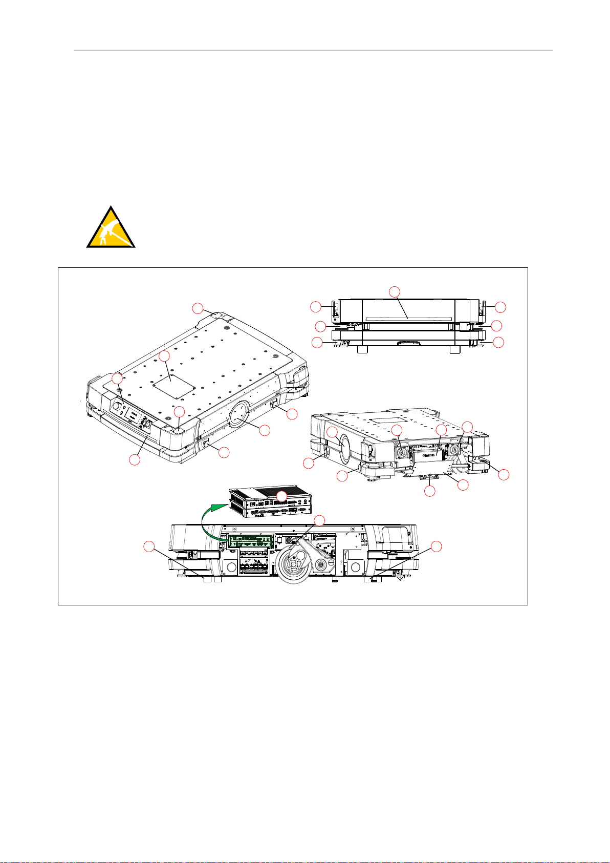
1.2 Product Description
The HD-1500 is a general-purpose mobile robot, designed to work in an indoor industrial
environment and around trained personnel. It is self-guided and self-charging, with an automated charging station. It has a maximum capacity of 1500 kg. Capacity includes the payload
structure and any load carried by that structure.
It’s Electrostatic Discharge (ESD) drive wheels discharge any accumulated electrical charge in
the AMR to ground which, if discharged into sensitive components of the AMR, could result
in serious damage of those components.
CAUTION: PROPERTYDAMAGE RISK
The AMR skins can accumulate electrical charge which, if discharged into ESD
sensitive devices, can cause damage to those devices.
11 HD-1500 Platform User's Manual 31500-000 Rev B
Figure 1-1. HD-1500 Platform Features
Page 13
Chapter 1: Introduction
B
C
A
E
D
F
Callout Description Callout Description
A Operator Panel with E-Stop But-
ton
B User Access Panel L Back Light Indication
C Wireless antenna x2 M High-Accuracy Positioning System
D Safety Scanning Laser x2 N
E Low Laser x2 O E-stop Button x4 (two on each side)
F Side Laser x2 - option P Front Caster x2, Rear Caster x2
G Light Disc x2 - one on each side
of the HD-1500
H Speaker x2 R AMR Controller
I Battery
J Battery Door
K Front Light Indication
(HAPS) x2 - option
Charging Contact x2 - top and bottom
Q Drive Wheel x2 - one on each side of
the HD-1500
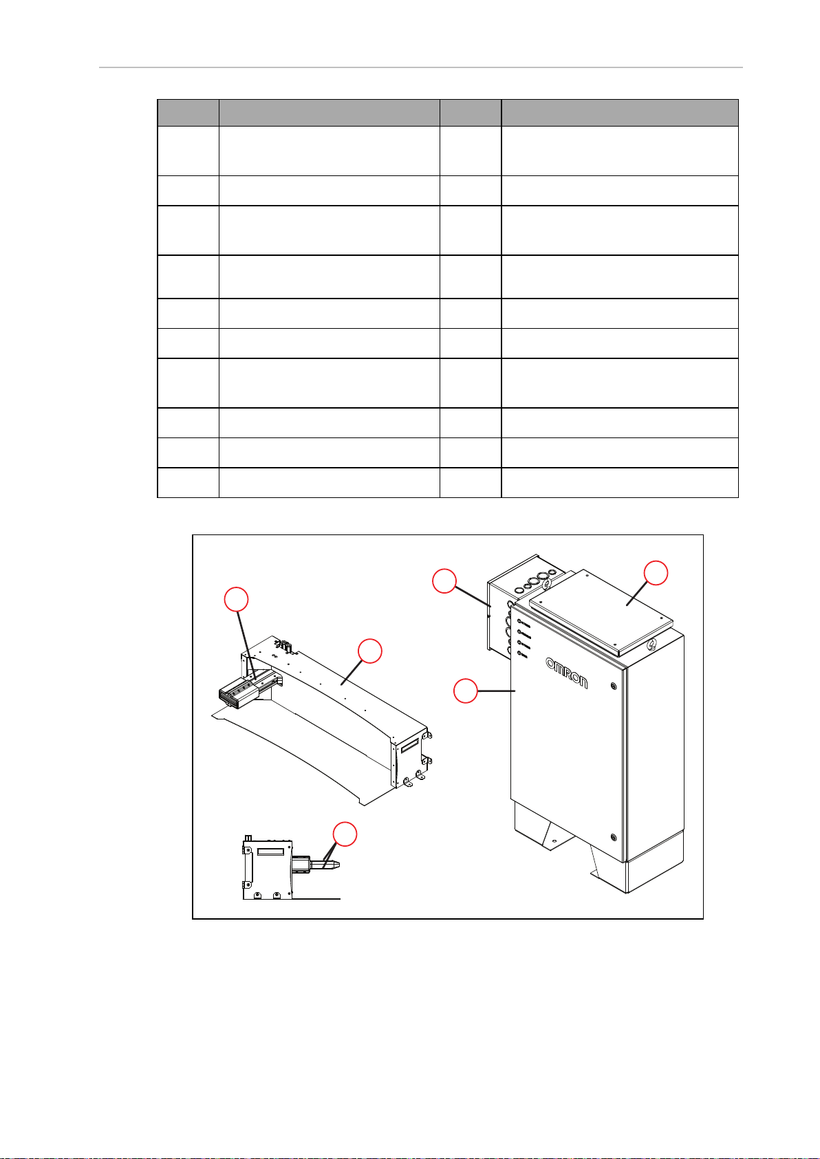
Figure 1-2. Charging Station Features
31500-000 Rev B HD-1500 Platform User's Manual 12
Page 14

1.2 Product Description
Callout Description Callout Description
A Power Supply Box D Docking Target
B Cooling Duct Cover E Charging Paddle
C Electrician Access Box F Charging Pads x2 - top and bottom
HD-1500 Autonomous Navigation
The HD-1500 combines hardware and mobile-robotics software to provide an adaptive, mobileplatform to transport your payload. The HD-1500 is equipped with Natural Feature Navigation system which enables the AMR to navigate, and perform its basic functions
independently and without the need for facility modification. After it scans physical features in
its environment, the HD-1500 navigates safely and autonomously to any accessible destination. It can move continuously and without human intervention, autonomously recharging
itself as necessary.
The HD-1500 uses range data from a Safety Scanning Laser as its primary means of detecting
obstacles and of maintaining an accurate understanding of its location in the environment.
Additionally, it uses data from the following sensors:
l
Two low lasers at the opposing corners of the AMR platform to detect objects below the
plane of the Safety Scanning Lasers.
l
Gyroscopes that detect and report HD-1500 rotational velocity.
l
Two encoders on each drive motor provide information on the distance traveled by
each drive wheel.
HD-1500 Localization
The encoders provide the navigation system with information on how far each wheel has
traveled, and in which direction. In addition, the Gyroscopes track the AMR's rotational velocity. The encoder information, combined with gyroscope data, is used to deduce the odometry.
The AMR analyzes this odometry data together with the data received from the safety scanning lasers, low lasers, and the side lasers to calculate its position within the map. This process is called localization.
Custom Payload Structures
For most applications, you will want to customize the platform with a payload structure,
attached to the top of the platform, for some combination of picking up, transporting, and dropping off your payload or material. The HD-1500 provides threaded mounting holes for payload attachment. The mounting holes provide a strong and adaptable method of attaching
payload structures to the chassis. A payload structure can be as simple as a crate that contains
manufacturing parts or a more sophisticated device such as a conveyor or robot arm. For more
information on designing a payload structure, see: Payload Structures on page 140.
The platform also provides a variety of interfaces and power connections to support your
application-specific sensors and accessories. For more information on available user connectors, see: Connectivity on page 154.
13 HD-1500 Platform User's Manual 31500-000 Rev B
Page 15
Chapter 1: Introduction
22
B
B
A
A
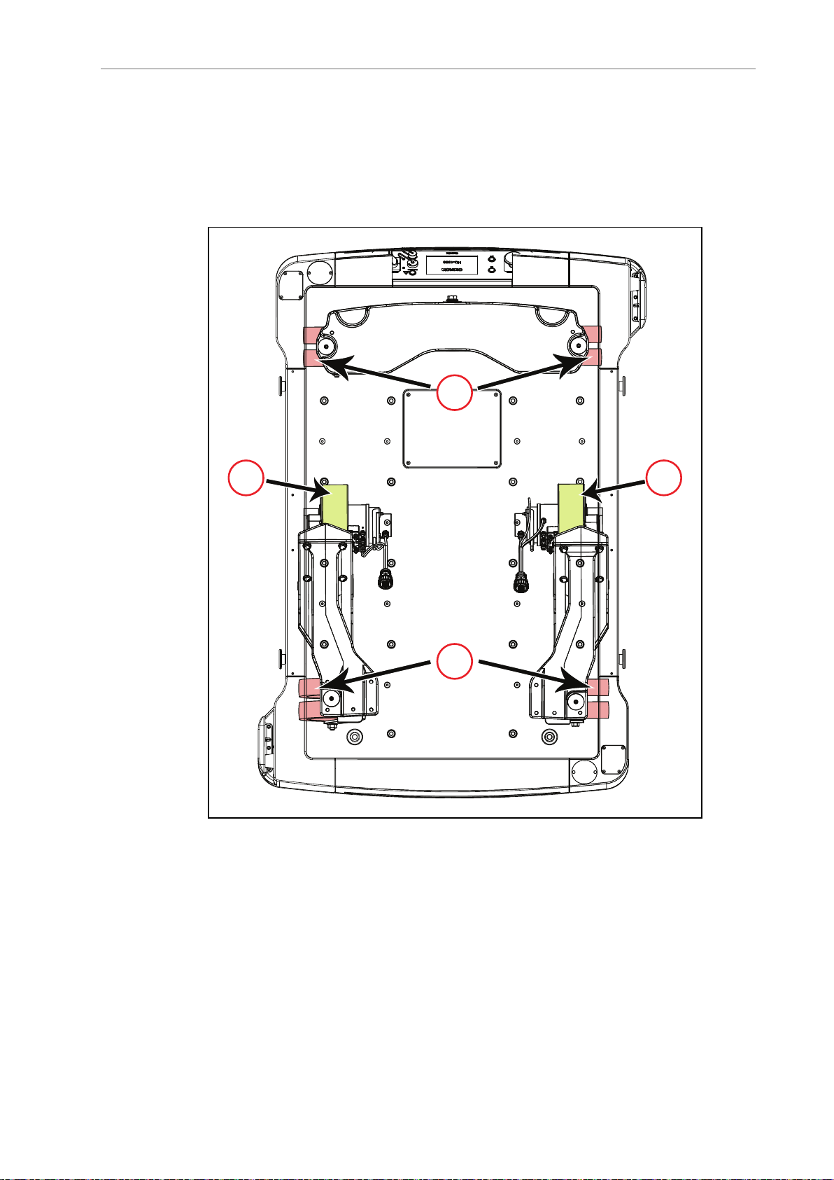
Body and Drive Train
The HD-1500 is a differential-drive AMR. It has two drive-wheels, and passive swivel-casters
at its front and rear for balance. The drive-wheels are mounted on the rocker arms, and have
solid polyurethane tread. Refer to the following figure for more information.
This drive style makes the HD-1500 highly maneuverable and allows it to rotate in place.
Figure 1-3. HD-1500Drive Train - Top View, (A)Casters, and (B) Drive Wheels
Each front caster is mounted to the same rocker arm as one of the drive-wheels. The two rear
casters are connected by another rocker that pivots about the AMR's longitudinal center-line.
This arrangement allows the AMR to maintain contact with the floor over uneven areas or
bumps, which benefits both traction and stability. Refer to the following figure for more information.
31500-000 Rev B HD-1500 Platform User's Manual 14
Page 16
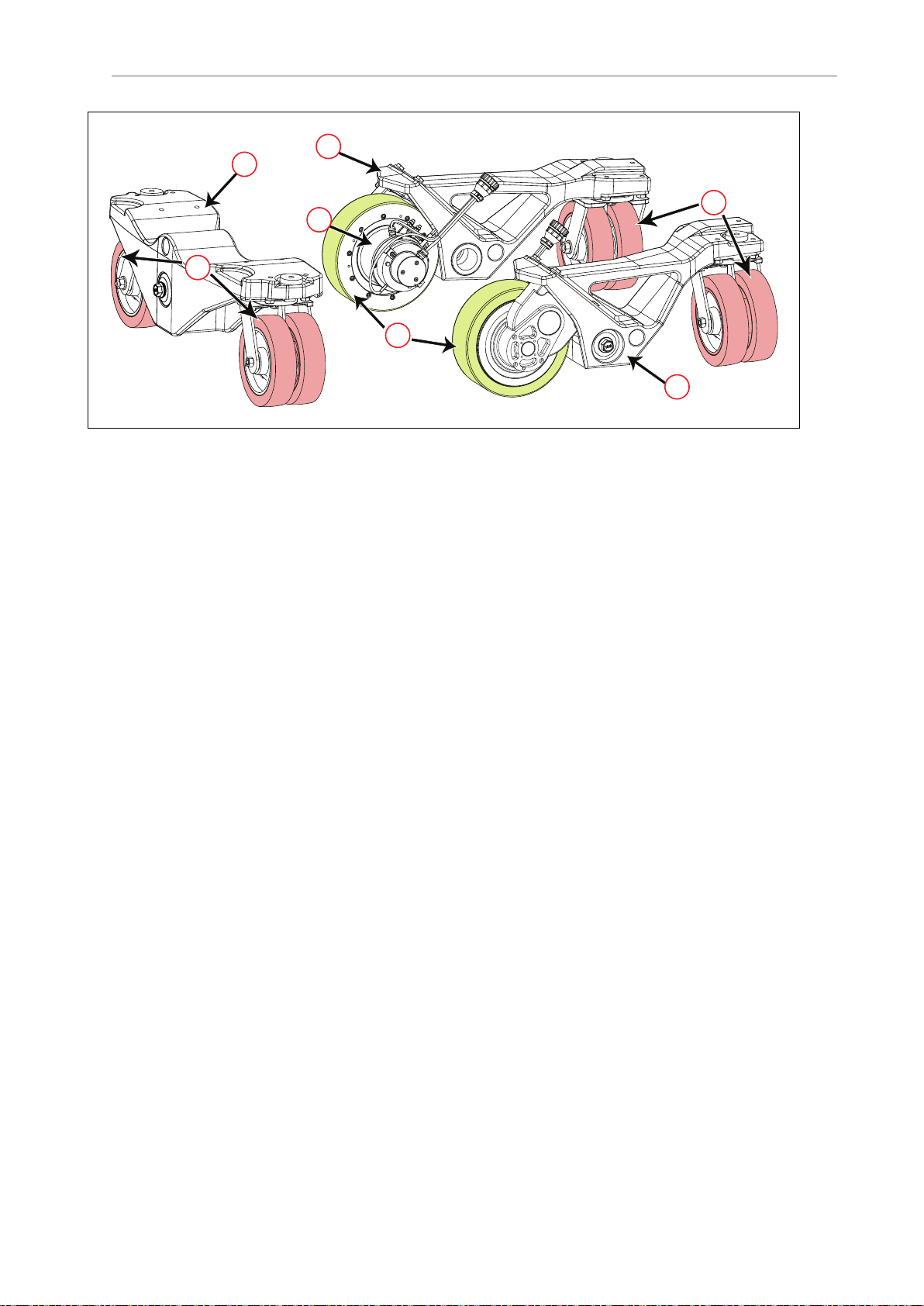
1.2 Product Description
A
A
B
C
C
D
C
Figure 1-4. HD-1500Drive Train (A) Casters, (B) Drive Wheels, (C) Rocker Arms, and (D) Drive
Motor (one on each drive wheel)
What's Included - Basic Components
One fully-assembled HD-1500Platform which includes:
l
Two OMRON OS32C Safety Scanning Lasers (main lasers).
l
Two low lasers.
l
Differential drive train.
l
Skins.
l
AMR Controller which includes:
o
A computing appliance that runs the SetNetGo operating system and the
Advanced Robotics Automation Management (ARAM) software.
o
A system that runs a variant of the Mobile Autonomous Robot Controller
(MARC), called Polo.
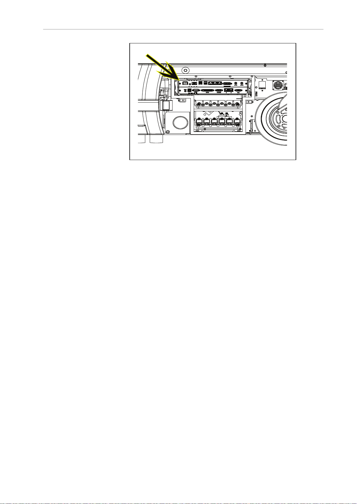
The AMR Controller comes pre-loaded with ARAM and Polo firmware, and the
SetNetGo OS. The AMR Controller is housed inside the platform as displayed in
the following figure.
15 HD-1500 Platform User's Manual 31500-000 Rev B
Page 17
Chapter 1: Introduction
Figure 1-5. AMR Controller in the Platform
o
Other sensors including inertial sensing for use with AMR controls.
l
One battery
Shipped separately from the platform to comply with dangerous goods shipping regulations.
l Five emergency stop (E-Stop) buttons:
o
One on the Operator Panel
o
Two on each side of the platform
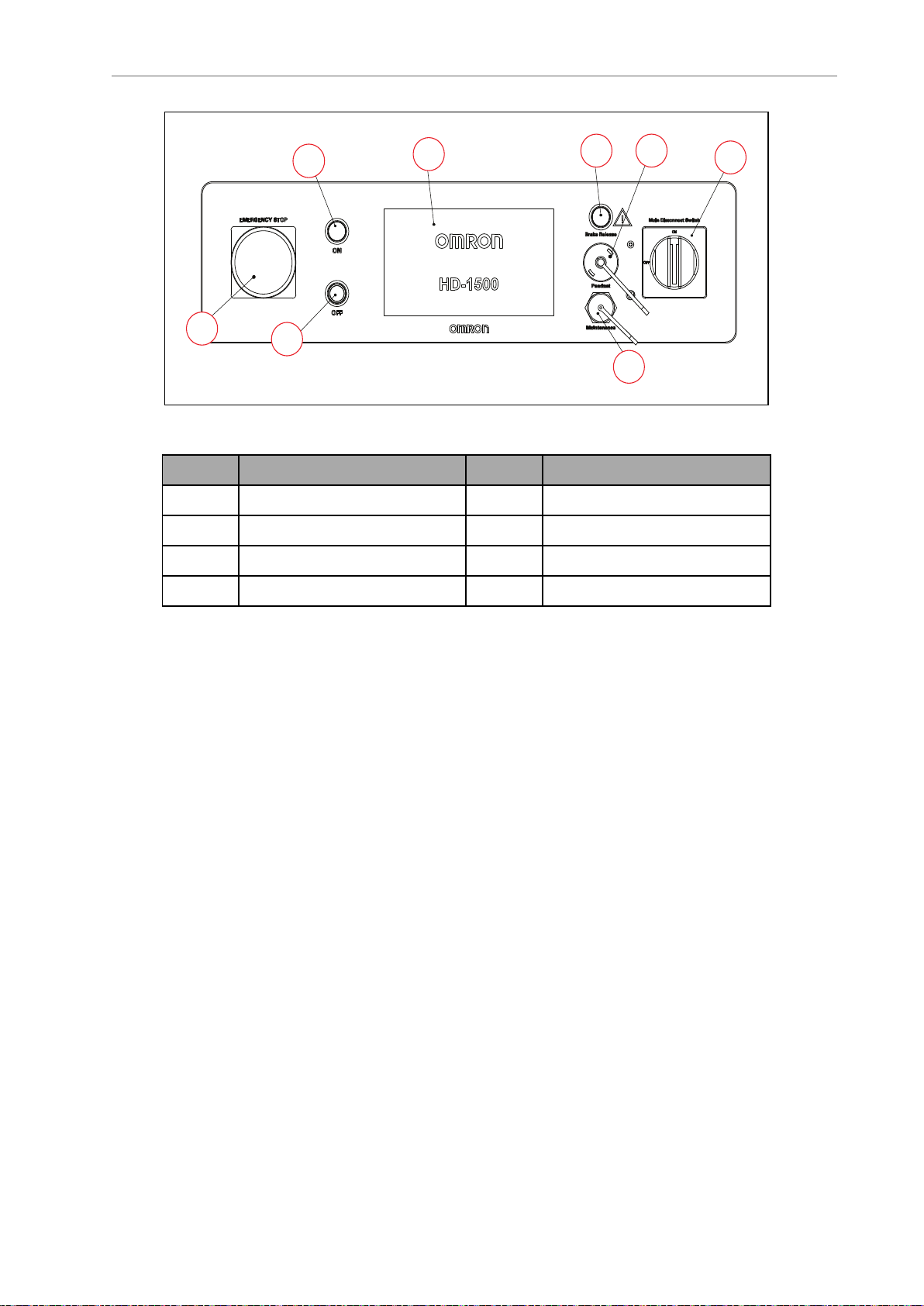
l Operator Panel
The Operator Panel includes a screen, an E-Stop button, ON and OFF buttons, a brake
release button, pendant port, Maintenance Ethernet connection, and a main disconnect
switch (which can be locked if needed). When the main disconnect switch is in OFF position (horizontal position), the power does not run through the AMR and therefore, the
AMR can not operate. To allow the power to run back through the AMR,you must turn
the main disconnect switch to ON position (vertical position), as displayed in the following figure.
You can move the operator panel to any preferred position on your payload structure.
However, because the operator panel contains one of the five E-Stop buttons, there are
important safety considerations when relocating or removing this panel. See: Positioning an Optional Payload E-Stop on page 202.
For information on the dimensions of the Operator Panel, see: Operator Panel on the
Payload on page 151.
31500-000 Rev B HD-1500 Platform User's Manual 16
Page 18
1.2 Product Description
B G
F
H
D
C
A
E
Callout Description Callout Description
A Emergency Stop (E-Stop) E Main Disconnect Switch
Figure 1-6. Operator Panel
H
F
Ethernet Connection
Display Screen
B Brake Release Button
C On Button G Pendant Connection
D Off Button
l
Automated charging station
The automated charging station enables the HD-1500 to charge itself, without user intervention. It includes wall and floor mount brackets, for a choice of installation methods.
See: Installing the Charging Station on page 115.
The charging cord that connects the Power Supply box to the Docking Target which can
also be used for charging a battery outside of the platform. See: Manually Charging the
AMR's Battery on page 195.
l
A USB flash drive containing software and documentation.
In addition to the items included with every HD-1500, you need at least one pendant per AMR
fleet. Use this pendant to manually drive the HD-1500 and to create a digitized map of the
work environment.
For a fleet of AMRs, the Fleet Operations Workspace Core (FLOW Core) software (running on
an EM2100 appliance) shares the map between all AMRs in the fleet. This provides a common
frame of reference for navigation and localization, preventing contention between AMRs.
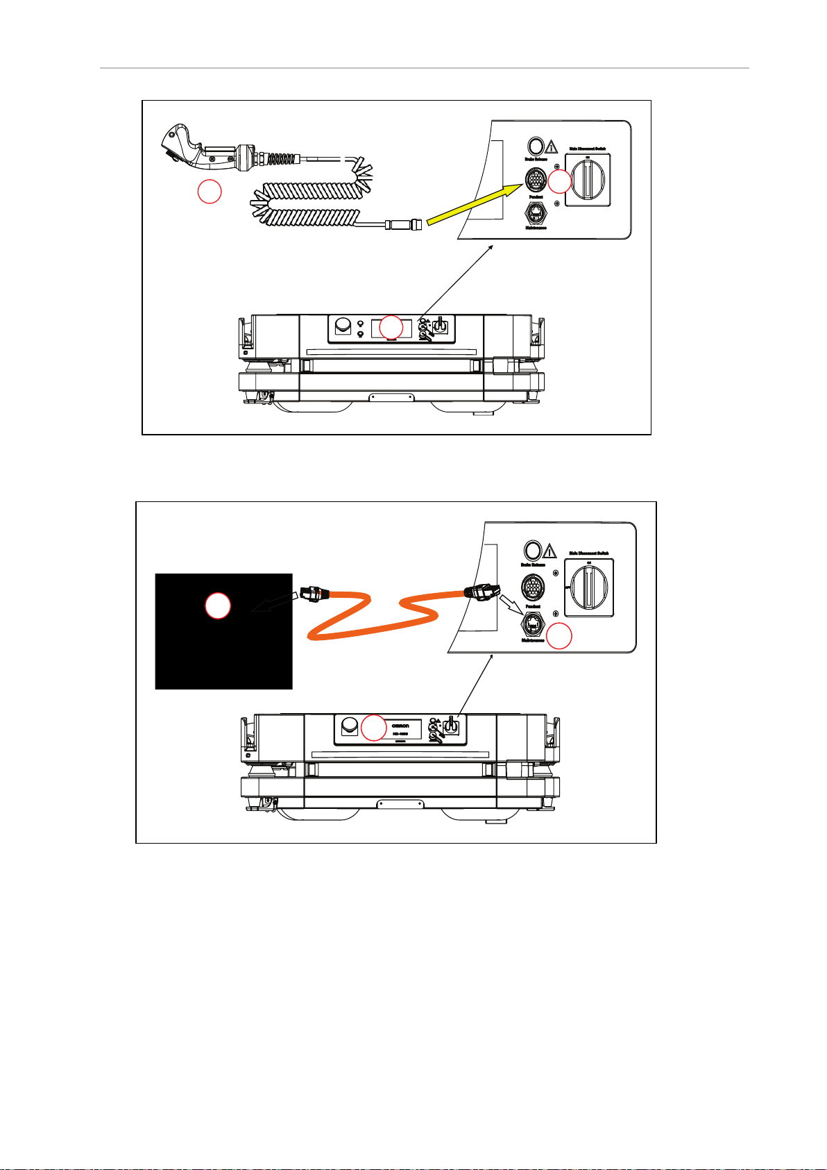
Figure 1-8. and Figure 1-9. display the location of the pendant, and the Ethernet ports on the
Operator Panel, installed on the rear of the HD-1500.
17 HD-1500 Platform User's Manual 31500-000 Rev B
Page 19
Chapter 1: Introduction
E
N
ABLED
P
OWER
A
B
C
D
E
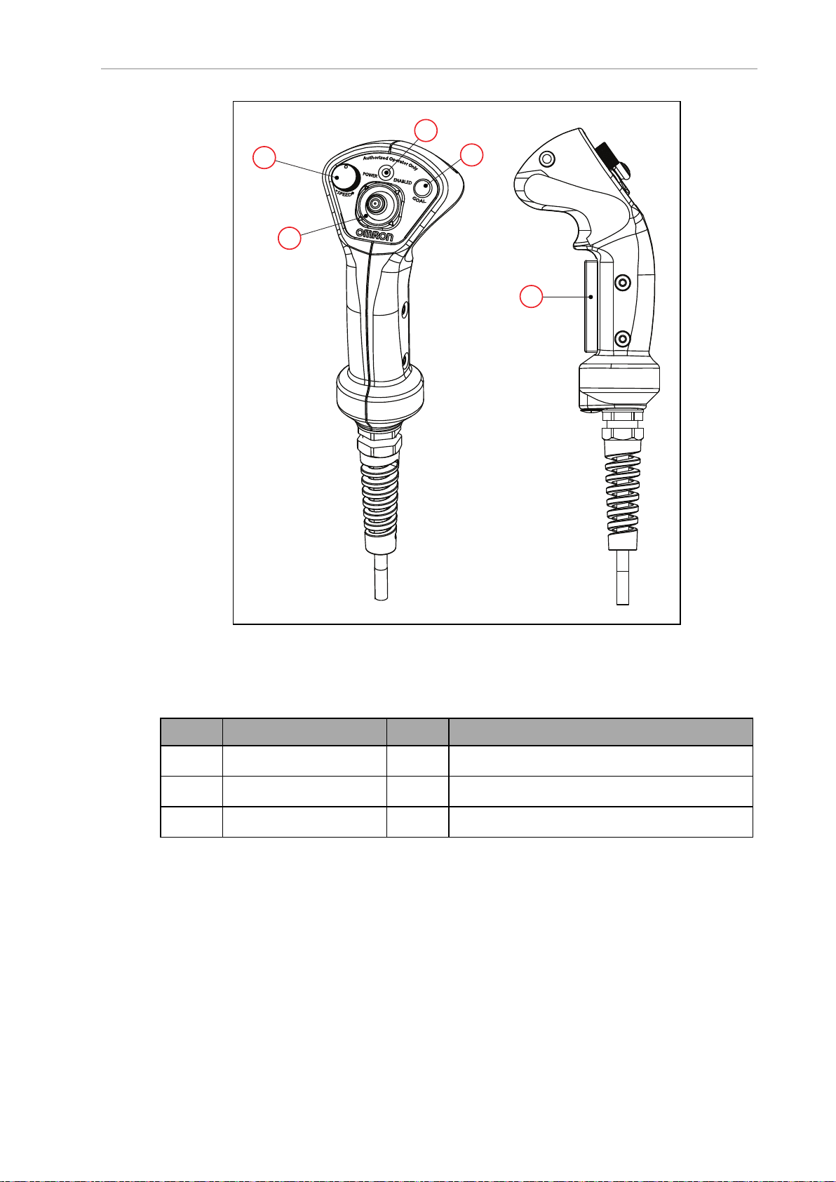
Figure 1-7. Pendant Controls
This is used for manually controlling the platform, mostly when making a scan to be used for
generating a map.
Callout Control Function Callout Control Function
A Speed control D Power indicator LED
B Goal button E Trigger switch Three-position enabling device
C Directional control stick
31500-000 Rev B HD-1500 Platform User's Manual 18
Page 20
1.3 Software Overview
A
C
B
A
C
B
Figure 1-8. (A) Pendant, (B) Pendant port on the Operator Panel, and (C) Operator Panel on the HD-
1500
Figure 1-9. (A) PC, (B) Maintenance Ethernet Port on the Operator Panel, and (C) Operator Panel on
1.3 Software Overview
Your HD-1500 requires the licensed software described in this section. Software is factoryinstalled on its AMR Controller.
19 HD-1500 Platform User's Manual 31500-000 Rev B
the HD-1500
Page 21
Chapter 1: Introduction
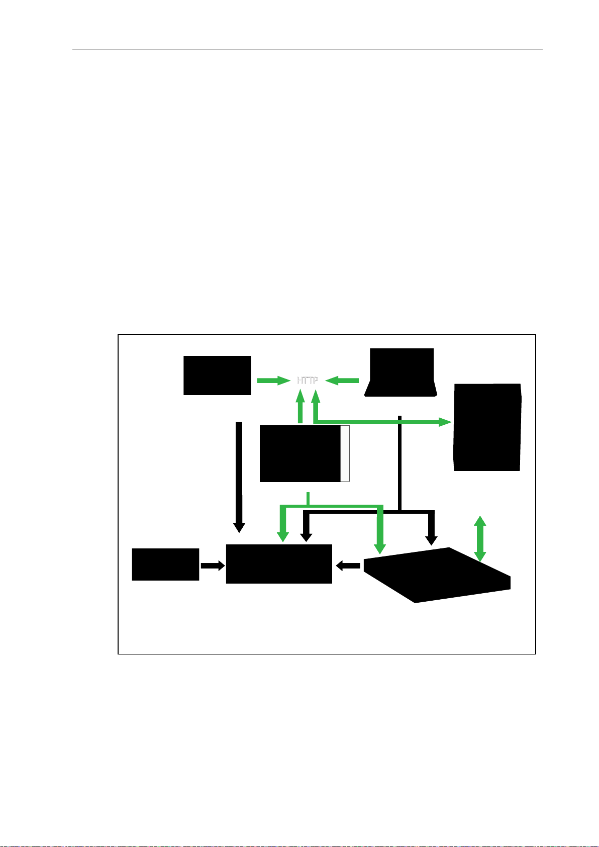
Fleet Manager Appliance
ARAMCentral
AMR Controller
SetNetGo OS
ARAM
ARCL Protocol
Polo
Operator Panel
Tablet
MobilePlanner
Operator PC
MobilePlanner
HTTP
SetNetGo UI
Manufacturing
Execution System/
Enterprise Resource
Planning System
Onboard Control Panel
Access to software features is permitted by use of a USB license dongle that contains secure,
encrypted electronic copies of the operating licenses. Some licenses might have a restricted
term and expire after a specific date. You will receive several warning alerts before the license
expires.
HD-1500 Software
The minimal operating configuration for an HD-1500 consists of the AMR managed by a
human operator using a Microsoft Windows® PC or optionally from an Android or iOS tablet.
If you have more than one AMR, you must install and configure an EM2100 appliance (running the Fleet Operations Workspace software) to manage multiple AMRs as a fleet. Fleet management prevents job contention or collisions between AMRs and provides efficient processing
of all tasks that you assign to the AMR fleet.
See the following documents for detailed information:
l
Enterprise Manager 2100 User's Guide (Cat. No. I631)
l
Fleet Operations Workspace Core User's Manual (Cat. No. I635)
Figure 1-10. shows the devices that you might use to manage one or more AMRs and the software components required for each device, if applicable.
Figure 1-10. Devices and Software in the AMR's Operating Configuration
31500-000 Rev B HD-1500 Platform User's Manual 20
Page 22

1.3 Software Overview
AMR administration includes both configuring and operating an AMR and also using the
AMR (or a fleet of AMRs) to perform useful work. The software that enables you to do this
management consists of:
l
The FLOW Core software, an integrated set of programs that run on different devices in
the environment (FLOW Core). You use the MobilePlanner or MobilePlanner Tablet
graphical interfaces to manage individual AMRs or fleets of AMRs. You can also access
lower-level functions through a command-line interface, ARCL. The Integration Toolkit
(ITK) can also be used to interface your MES or WMS system with the Fleet Manager.
l
The SetNetGo OS, a host operating system (OS) that provides a Web interface you use to
assign network addresses, perform configuration, upgrade software, and obtain debugging files.
User-Supplied Components and System Requirements
To configure and manage an HD-1500 you require a personal computer (PC) running a supported version of Microsoft Windows
l
200 megabytes of available hard-disk storage.
l
Ethernet connection. OMRON recommends that you use a stable and high-speed wire-
®. The PC requires:
less connection.
Additional Information: Wireless is a requirement for managing multiple AMRs
as a fleet. See: Fleet Operations Workspace Core User's Manual (Cat. No. I635).
Also, you may optionally use an Android or iOStablet to run the MobilePlanner Tablet software.
ARAM
The Advanced Robotics Automation Management software (ARAM) runs on the AMR Controller. ARAM is responsible for the following AMR functions and features:
l
Interaction with on-board sensors such as the safety scanning lasers, low lasers, and
optional side lasers.
l High-level, autonomous robotics functions such as:
o
Obstacle avoidance
o
Path planning
o
Localization
o
Navigation
l
Motion commands to the Polo firmware.
l
Battery management.
ARAM provides the AMR with an interface to external entities by managing the following:
l
Wired and wireless Ethernet communications with external software for external monitoring, development, and systems coordination.
l
Fleet coordination of AMRs through the optional Fleet Manager.
21 HD-1500 Platform User's Manual 31500-000 Rev B
Page 23

Chapter 1: Introduction
l
Integration with other systems.
l External monitoring, setup, and control via the MobilePlanner graphical interface.
l
Digital and analog I/O ports accessible from the user access panel that enable you to
integrate application-specific sensors and effectors into your payload structure. Refer to
Fleet Operations Workspace Core User's Manual (Cat. No. I635) for instructions on how
to configure I/O connections.
ARAMCentral
ARAMCentral runs on the Fleet Manager as part of the Fleet Operations Workspace software.
When managing a fleet, the ARAMCentral software does the following:
l
Stores and distributes:
o
The shared workspace map used by all AMRs in a fleet.
o
The common AMR configuration.
l
Controls AMR traffic, including:
o
Multi-AMR avoidance
o
AMR Destinations
o
AMR Standby
o
Charging dock access
l
Queuing of jobs
l
Remote I/O (if used)
MobilePlanner Administrator Mode
MobilePlanner is part of the Fleet Operations Workspace software and runs on the user's PC,
or as a portable tablet version (on Android and iOS tablets). It provides a tabbed graphical
user interface on the PC and a touchscreen interface on tablets. Depending on your level of
access (controlled by your account) the graphical interface provides many options, including:
l
Managing AMR fleet jobs.
l
Creating and editing workspace maps.
l
Accessing the AMR through the SetNetGo Web interface.
l
Commissioning and configuring an AMR and modifying its configuration by changing
ARAM parameters.
l
Issuing custom ARCL commands.
Operator access or View access restricts the tasks that you can perform when using
MobilePlanner.
Before you assign tasks to an AMR, you use MobilePlanner to create and edit a digitized map
of its work space. During this procedure, you use the pendant to drive the AMR around the
workspace. In mapping mode, the safety scanning laser scans features of the workspace, such
as walls, columns, doorways and corners. After you create the map, you open it in
31500-000 Rev B HD-1500 Platform User's Manual 22
Page 24

1.3 Software Overview
MobilePlanner and edit it to add or remove features. For example, if there is an area of the
map where you want the AMR to follow a specific path, you can draw a PreferredLine feature
on the map. Be aware that the AMR will deviate from the PreferredLine if an obstacle enters its
path.
You then use MobilePlanner to configure ARAM operating parameters that control the AMR's
operation in the mapped workspace. For example, you might assign a preferred charging Station (docking target) to the AMR or the Fleet Manager by specifying the unique map identifier
for that docking target. This configuration can be shared with identically-equipped AMRs in
your fleet. The map generated by one AMR can be shared across a fleet, with both identical
and non-identical OMRON AMRs.
Refer to the separate Fleet Operations Workspace Core User's Manual (Cat. No. I635) for instructions about mapping a workspace and preparing the virtual elements, goals, routes, and tasks
for your application. In particular, refer to the descriptions of the following software options:
l
Working With Map Files - Editing a Map File
l
Using the Drawing Tools - Adding Goals and Docks
MobilePlanner, Operator Mode
MobilePlanner can operate in a restricted Operator mode that permits only limited access to
user interface features and functions.
MobilePlanner’s Operator Mode allows you to monitor one or more AMR's activities and
assign tasks in the mapped space. For more information, see: Fleet Operations Workspace Core
User's Manual (Cat. No. I635).
Polo
The AMR Controller contains a powerful multi-processor that runs the Polo firmware.
This firmware controls low-level AMR functions, including:
l
Maintaining the AMR’s driving speed and heading (direction of travel).
l
Acquiring sensor data from the encoders, and internal orientation sensors.
l
Reading emergency stop (E-Stop) status to enable and disable the drive motors.
l
Reading pendant input.
l
Computing and reporting the AMR's odometry (the change in X, Y coordinates and the
heading) and other low-level operating conditions to the ARAM software.
ARCL Protocol
The Advanced Robotics Command Language (ARCL) is a programming language integrated
into ARAM and ARAMCentral. Its operating format is a text-based command and response
server. Use ARCL to integrate an AMR (or fleet of AMRs) into an external automation system.
You do not need access to MobilePlanner to use ARCL.
Typical uses of ARCL are:
l
Operating and monitoring the AMR.
l
Operating accessories and peripherals.
23 HD-1500 Platform User's Manual 31500-000 Rev B
Page 25

Chapter 1: Introduction
l
Sending commands to your payload structure.
For more information, See: Advanced Robotics Command Language Reference Guide.
Integration Toolkit (ITK)
The Integration Toolkit (ITK) is OMRON's newest interface application enabling the integration
of Fleet Manager with the end user's client application. ITK facilitates the full management
and monitoring of all AMR job types, and allows tracking of the AMR data directly. ITK has a
flexible architecture which provides multiple, and simultaneous communication channel
options allowing the user to command, and monitor fleet operations using Rest, SQL, and/or
RabbitMQ. These communication channels provide flexibility, and choice in how a system
interacts with an AMR fleet, and the Fleet Manager.
ITK runs only on the Fleet Manager.
For more information, refer to: Fleet Operation Workspace Core Integration Toolkit User’s Guide
(Cat. No. I637).
SetNetGo
The SetNetGo OS runs on the AMR Controller and EM2100 appliance. It is the host OS in
which the FLOW components ARAM and ARAMCentral run. SetNetGo has a Web interface
that you access either from a Web browser or from within MobilePlanner as a tab. After you
use a wired Ethernet connection to configure the AMR's wireless settings you may choose to
enable wireless access to SetNetGo from the web interface's Security tab.
To access the SetNetGo web interface, at a minimum, you need:
l
A hardwired connection to the HD-1500 Maintenance Ethernet port, located on the Operator panel.
l
A LANconnection or direct Ethernet port connection to the EM2100 maintenance port.
Your ITdepartment can use SetNetGo to configure network settings without using MobilePlanner.
Use SetNetGo to configure Ethernet settings, upgrade software, or perform diagnostics such as
retrieving log files.
1.4 How Can I Get Help?
Refer to the OMRON corporate website: http://www.ia.omron.com.
Related Manuals
This manual covers the installation, setup, operation, and maintenance of an HD-1500. There
are additional manuals that cover configuring the platform. See the following table. These
manuals are available on the USB flash drive delivered with your HD-1500.
Manual Title Description
Table 1-1. Related Manuals
Mobile Robot HDSafety Manual (Cat.
No. I647)
Contains general safety information for all OMRON
HD-1500-based AMRs.
31500-000 Rev B HD-1500 Platform User's Manual 24
Page 26

1.4 How Can I Get Help?
Manual Title Description
HDPlatform Peripherals User's Manual
(Cat. No. I646)
Safety Laser Scanner OS32C Series
User's Manual (Cat. No. Z296-E1)
Fleet Operations Workspace Core User's
Manual (Cat. No. I635)
Enterprise Manager 2100 User's Guide
(Cat. No. I631)
Fleet Simulator User's Manual (Cat. No.
I649)
Fleet Operation Workspace Core Integration Toolkit User’s Guide (Cat. No.
I637)
Advanced Robotics Command Language Enterprise Manager Integration
Guide (Cat. No. I618)
Covers peripherals, such as the , Side Lasers, HAPS,
and Acuity Localization options.
Describes the use of the OS32C laser.
Describes Fleet management, MobilePlanner software, the SetNetGo OS, and most of the configuration procedures for an HD-1500.
Describes the installation of an EM2100 appliance,
which runs the Fleet Operations Workspace software
to manage a fleet of AMRs.
Describes the configuration and use of the Fleet Simulator software on an EM2100 appliance.
Contains information that is necessary to use the
Integration Toolkit facilitating integration between
the Fleet Manager and the end user's client application.
Describes how to use the Advanced Robotics Command Language (ARCL) a text-based, command line
operating language Use ARCL to integrate a fleet of
AMRs with an external automation system.
Support
Contact your OMRON representative if you have further inquiries with your HD-1500 that are
not described in this manual.
When you contact support, it is useful to provide a DebugInfo file. This is a collection of configuration, log, and system status files that support personnel can use for debugging and
troubleshooting.
Visit the OMRON Web site for your locale to obtain local support telephone numbers and
information.
Download a Debuginfo File for Support
You can download a debuginfo file for troubleshooting problems or if you need to contact your
OMRON representative.
If your HD-1500 is already configured to use a wireless network:
1.
Open MobilePlanner and connect to the AMR's IP address.
2.
Click the SetNetGo tab to open its Web Interface.
3.
Click Status and select Debug Info from the left pane.
4.
Click Download Debug Info and then specify a location to save the file.
Otherwise, you must first create a TCP/IP connection to the AMR's Maintenance Ethernet port
as described in: Network Setup on page 26.
25 HD-1500 Platform User's Manual 31500-000 Rev B
Page 27

Chapter 1: Introduction
Network Setup
If you have not configured your HD-1500 for access over a wireless network, you must follow
the instructions provided in Maintenance Ethernet Connection on page 128. This is when you
use a hardwired connection to the HD-1500 Maintenance Ethernet port.
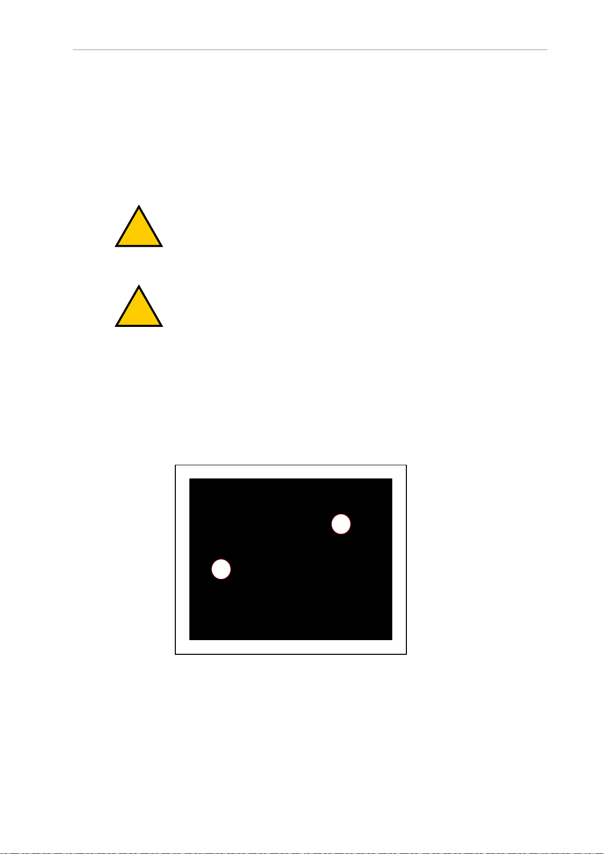
Obtain a DebugInfo File from SetNetGo
After you access SetNetGo as described in the preceding sections, you will see the following
screen:
1.
In the SetNetGo screen, click the Status tab and then select Debug Info to activate the
Download debug info button.
2.
Click Download debug info.
3.
When prompted, save the downloaded file, and attach it to your support request email.
See: Support on page 25.
Figure 1-11. SetNetGo Status Tab
31500-000 Rev B HD-1500 Platform User's Manual 26
Page 28

Page 29

This chapter provides an overview of important safety considerations for your HD-1500. All
!
!
!
persons operating or working in the vicinity of an HD-1500 must thoroughly read and understand this information. For more information on safety, refer to the Mobile Robot HDSafety
Manual (Cat. No. I647).
2.1 General Hazards
This section describes potentially hazardous situations and conditions.
WARNING: The following situations could result in injury or damage to the
equipment.
l
Do not ride on the AMR.
l
Do not exceed the maximum weight limit.
l
Do not drive the AMR on inclined floors or surfaces.
l
Do not exceed the maximum recommended speed, acceleration, deceleration, or rotation
limits. See Center of Gravity (CG) on page 147 and Acceleration, Deceleration, and Rotation Limits on page 136.
Chapter 2: Safety
Rotational speed becomes more significant when the payload’s center of gravity is
increasingly offset from the AMR's center of gravity.
l
Do not drop the AMR, run it off a ledge, or otherwise operate it irresponsibly.
CAUTION: PERSONALINJURYRISK
The user must not stand close to the AMR while it is rotating with no
forward motion.
l
Do not allow the AMR to drive through an opening that has an automatic gate or door
unless the door and AMR are configured correctly with the Call/Door Box option.
l
Do not throw an object in front of the AMR or suddenly step into the path of the AMR.
The AMR braking system cannot be expected to function as designed and specified in
such instances.
WARNING: PERSONALINJURYORPROPERTYDAMAGERISK
Abrupt appearance of objects or persons in the path of the AMR could
result in personal injury or property damage. You must make sure that
the operating environment of the AMR is adequately controlled.
l
Do not expose the AMR to rain or moisture.
l
Do not use unauthorized parts to repair the AMR.
31500-000 Rev B HD-1500 Platform User's Manual 28
Page 30
2.2 Unprotected Areas
!
!
A
B
l
Do not power on the AMR without its wireless antennas in place.
l
Although the lasers used are Class 1 (eye-safe), OMRON recommends that you not look
into the laser light.
l
Reflective surfaces can interfere with the AMR's laser operation.
l
Do not operate the AMR in areas where it may be exposed to intense interference light,
such as direct sunlight.
l
Do not operate the AMR in a flammable gas environment.
l
Do not operate the AMR with the safety interlock switches disabled.
WARNING: PERSONALINJURYORPROPERTYDAMAGERISK
Do not operate the AMR in hazardous environments where there is
explosive gas, and oil mist.
WARNING: ELECTRICAL SHOCKRISK, FIRERISK, BURNRISK
The safety interlock switches shall not be defeated or bypassed as this
could potentially result in short circuit.
l
The HD-1500 shall only be powered by an HD-1500 battery. Do not use any other batteries.
l
The HD-1500 battery shall only be charged by an HD-1500 charger. Do not use any
other chargers.
2.2 Unprotected Areas
The HD-1500 charges its battery autonomously by driving itself to the docking target where it
mates with the docking target's charging paddle, as displayed in the following figure.
Figure 2-1. HD-1500 Mating with the Charging Paddle, (A) HD-1500, and (B) Charging Paddle
29 HD-1500 Platform User's Manual 31500-000 Rev B
Page 31

Chapter 2: Safety
!
!
The HD-1500 travels at a low speed when docking:
l
When traveling between 0 to 20 mm/s (or angular speed of less than 3 deg/s), there are
no hardware-based safety laser protection zones. The HD-1500 beeps any time it moves
at a linear speed below 20 mm/s, or an angular speed of less than 3 deg/sec for longer
than 2 seconds. The AMR respects its software-based obstacle-avoidance clearances at
all speeds, but it will not use a hardware-based safety laser protection zone at speeds
below 20 mm/s or 3 deg/sec. This is done intentionally to allow operators to manually
drive the AMR away from any obstacles that are too close to the AMR. It also allows
the operators to back the AMR when needed.
l
At speeds between 20 to 115 mm/s (or angular speed of less than 12 deg/s), the AMR's
hardware-based laser protection zones exclude the area where the charging paddle
enters the laser channel. The safety zones of the two safety scanning lasers are identical,
and therefore, the unprotected areas are present at both front and rear ends of the AMR.
The operator must take necessary precautions to ensure that the operator's hands or
other body parts do not get stuck in between the charging pad and the platform when
docking.
l
At speeds above 115 mm/s, the hardware-based laser protective zones are fully active
and there are no unprotected areas.
The following table lists the hardware-based safety laser protection zones for the speeds mentioned in the preceding paragraph:
Table 2-1. Hardware-Based Safety Laser Protective Zones
Linear speed
(mm/s)
0≥ and < 20 0≥ and <3 No protective zones.
20≥ and <115 3≥ and <12 Two unprotected areas. Area
≥115 ≥12 No unprotected areas.
CAUTION: PERSONALINJURYORPROPERTYDAMAGERISK
Although the AMR respects its software-based obstacle-avoidance clearances at
all speeds, the user must be aware of the location of the E-Stop buttons at all
times, and keep out of the unprotected areas.
CAUTION: PERSONALINJURYORPROPERTYDAMAGERISK
It is the end user's responsibility to ensure that the area within the radius of
2 m from the center of the HD-1500 is kept clear, when the AMR is traveling at
less than 115 mm/s.
Angular speed
(deg/s)
Hardware-based safety laser
protective Zones
where the charging paddle enters
the laser channel (both at front
and rear of the AMR).
31500-000 Rev B HD-1500 Platform User's Manual 30
Page 32

2.2 Unprotected Areas
A
B
C
D
E
F
F
A
B
Figure 2-2. HD-1500 Protective Zones with Openings for the Charging Paddle - Movement at Less
Than 115 mm/s (Dimensions are in mm)
ID Description ID Description
A AMR Y-axis D Front laser zone
B AMR X-axis E HD-1500
C Rear laser zone F Safety scanning laser
The following figure provides dimensions of the HD-1500 unprotected area. The same dimensions are true for the rear laser unprotected area.
Figure 2-3. HD-1500's Unprotected Zone Dimensions - Movement at Less Than 115 mm/s, (A) AMR
Y-Axis, and (B) AMR X-Axis
31 HD-1500 Platform User's Manual 31500-000 Rev B
Page 33

2.3 What to Do in an Emergency
!
In case of an emergency such as a fire or collision, you should stop the AMR quickly and
safely. If the emergency situation is near the charging station, you must turn off the power
using the main disconnect switch. See Figure 7-10.
CAUTION: Combustible LithiumBattery.
For AMR fire suppression use either foam, dry chemical extinguisher, ABC, AB,
powdered graphite, copper powder, or a CO2extinguisher.
The HD-1500 has four E-Stop buttons, two on either side of the platform (a red push-lock button). The Operator Panel provides an additional E-Stop button (a red push-lock button on a yellow background). See the following figures.
Chapter 2: Safety
Figure 2-4. E-Stop Button on the Platform
Figure 2-5. E-Stop Button on the Operator Panel
Use the User Safety Interface connection, located on the user access panel, to add E-Stop buttons to your payload structure, if required. See: SCPU on page 165.
31500-000 Rev B HD-1500 Platform User's Manual 32
Page 34

2.3 What to Do in an Emergency
In the event of an emergency stop:
l
The AMR uses motor power to come to a controlled stop then engages its motor brakes
and removes power to its drive motors.
l
Indicator lights on the AMR, and the pendant (if attached) show the E-Stop state. See:
Light Discs and Beacon on page 204 and Front and Back Light Strips on page 208.
A user-initiated E-Stop differs from a laser-initiated protective stop (they both are category 1
stop). The latter occurs when one or both of the AMR's safety scanning laser detects an object
within its protected zone. In such cases, the AMR safely stops, and then resumes operation
after a delay of at least two seconds, and after confirming that its protected zone is clear of
obstacles. See: Protective Stops Initiated by AMR Safety Lasers on page 50.
An emegency stop initiated by pressing one of the E-Stop buttons, is a controlled stop function.
In this case, the power to the AMR motors remains on in order to achieve a controlled stop.
Once the controlled stop is achieved, the power to the motors is disconnected. If for any reason
the controlled stop function fails or does not function as expected, the power will still be disconnected to the motors. Activating an emergency stopby pressing one of the E-Stop buttons
requires manual deactivation of the E-Stop button, and manual reset of the AMR through the
ON button for the AMR to restart its operation. The AMR will not automatically recover from
an emergency stop initiated by pressing one of the E-Stop buttons on the AMR.
To use an E-Stop button:
1. Push firmly on the red button so that it latches.
2.
Follow your site-specific emergency and safety procedures.
If you need to move the AMR manually after correcting the emergency condition, press and
hold the brake release button and move the AMR. You can also use the pendant to drive the
AMR manually, if it is safe to do so. In order to use the pendant, you must first release the
E-Stop.
To enable the AMR's drive motors and put it back into service, follow the procedure described
in: Releasing an E-Stop on page 35.
Releasing the Brakes
In case of an emergency or abnormal situation, the AMR can be manually moved. However,
only qualified personnel who have read and understood this manual and the Mobile Robot
HDSafety Manual (Cat. No. I647) should manually move the platform. The brakes on the drive
wheels can be released with the brake release button. This requires battery power, and an EStop must be pressed on the AMR.
NOTE: You should move the HD-1500 manually only when absolutely necessary during an emergency, for safety, or if it is lost or stuck. If you find that you
must frequently move the HD-1500, use MobilePlanner to reconfigure its route to
avoid problem areas.
33 HD-1500 Platform User's Manual 31500-000 Rev B
Page 35

Chapter 2: Safety
!
!
!
WARNING: PERSONALINJURYORPROPERTYDAMAGERISK
Using the brake release button while the HD-1500 is positioned on a slope of
greater than 3% will cause the HD-1500 to roll down. You must not use the
brake release button to move the HD-1500 manually, when positioned on a
slope of greater than 3%, unless necessary precautions have been taken to prevent uncontrolled rolling of the HD-1500. The HD-1500 is not intended to be
operated on ramps or sloped surfaces.
CAUTION: PERSONALINJURYORPROPERTYDAMAGERISK
Pushing an HD-1500 requires significant effort and might cause personal
injury or property damage. Take appropriate care and follow all safety instructions.
WARNING: PINCHRISK
Take necessary precautions when moving an
AMRwithout its skins attached. The motor and
motor assemblies will be exposed when the side
skins are removed, exposing the potential pinch
points. Refer to the following figure.
The rear and top of the AMR also pose pinch
hazard when the rear skin and the top plate are
removed.
Figure 2-6. Side Skin Removed - Exposing Motor and Motor Assemblies
Application-specific attachments can affect an AMR's stability. All operators should know the
locations on the AMR (or its payload) where they can push safely without tipping the AMR
over or damaging its components. This should be as low as possible and near the center of
gravity.
OMRON recommends that you train personnel on the safe use of the brake release button, and
procedures for safely pushing an HD-1500. For instructions on how to safely use the brake
release button, see: Brake Release Button on page 203.
31500-000 Rev B HD-1500 Platform User's Manual 34
Page 36

2.4 Dangers, Warnings, and Cautions
!
!
!
!
CAUTION: PERSONALINJURYRISK
The pushing locations of the AMR are low. You must use safe pushing/
pulling practices when manually moving the AMR.
Releasing an E-Stop
This section describes how to release an E-Stop and bring the AMR back into service.
CAUTION: PERSONALINJURYORPROPERTYDAMAGERISK
If an AMR’s E-Stop is triggered, ensure that the cause of the E-Stop is resolved,
and all surrounding areas are clear before releasing the E-Stop.
To release an E-Stop:
1.
Make sure that all surrounding areas are clear before you release the E-Stop button so
that the AMR has room to maneuver.
2.
Rotate the E-Stop button in the direction of the arrows on the button and allow it to pop
up.
3.
After you release the E-Stop button, you must enable the motors manually by pressing
the green ON button on the operator panel.
After you enable the motors there is a delay of several seconds before the AMR can resume
operation.
NOTE: If you manually move the AMR while it is powered off, it may not be
able to determine its current location. Use the localization feature in MobilePlanner to localize the AMR.
Enabling motor power, either at the start-up or after an E-Stop release, must be done through a
manual action at the system, and only after the operator has confirmed that it is safe to return
the AMR to operation. Enabling the motor power must be an additional act after releasing an
E-Stop, and it is done by pressing the Operator Panel's On button.
2.4 Dangers, Warnings, and Cautions
Alert Levels
There are three levels of alert notation used in this document. In descending order of importance, they are:
DANGER: Identifies an imminently hazardous situation which, if not
avoided, is likely to result in serious injury, and might result in fatality or
severe property damage.
WARNING: Identifies a potentially hazardous situation which, if not avoided,
will result in minor or moderate injury, and might result in serious injury, fatality, or significant property damage.
35 HD-1500 Platform User's Manual 31500-000 Rev B
Page 37

Chapter 2: Safety
!
!
!
CAUTION: Identifies a potentially hazardous situation which, if not avoided,
might result in minor injury, moderate injury, or property damage.
Alert Icons
The icon that starts each alert can be used to indicate the type of hazard. These will be used
with the appropriate signal word - Danger, Warning, or Caution - to indicate the severity of the
hazard. The text following the signal word will specify what the risk is, and how to avoid it.
Icon Meaning Icon Meaning
Falling Hazards
This is a generic alert
icon. Any specifics on the
risk will be in the text following the signal word.
This identifies a hazardous electrical situation.
This warning icon warns
against riding on the
AMR.
This warning icon warns
against hazardous
magnetic field.
This warning icon warns
against a pinch hazard.
This identifies a hazardous burn-related situation, or a Hot surface.
This identifies a hazardous ESD situation.
This identifies a fire risk.
This identifies a tip hazard.
WARNING: PERSONALINJURYORPROPERTYDAMAGERISK
The AMR can cause serious injury to personnel or damage to itself or other
equipment if it drives off of a ledge, such as a loading dock, or down stairs.
Physical Barriers
Use physical barriers together with logical barriers (map restrictions) to prevent the AMR from
approaching any fall hazard that is within its operating area. Such hazards include:
l
The edge of a loading dock or ramp.
l
Entrance to downward stairs.
l
Any other vertical drop that exceeds the AMR's maximum step height.
31500-000 Rev B HD-1500 Platform User's Manual 36
Page 38

2.4 Dangers, Warnings, and Cautions
Required characteristics of physical barriers are:
l
Strength—The barrier must be attached to a solid wall or floor and should be strong
enough to stop a fully-laden AMR traveling at maximum speed.
l Continuity—The barrier must extend around the hazard completely.
l
Visibility—Mark all physical barriers to make sure that the AMR's safety lasers can
detect them easily. Barriers must extend above and below the laser's sensing plane, particularly if the floor is not flat.
Logical Barriers
In addition to physical barriers, use MobilePlanner to create forbidden areas or lines on the
workspace map to prevent AMRs from closely approaching a fall hazard. These restrictions
must be continuous so that the AMR cannot plan a path around the logical barrier.
The map features mentioned in the preceding paragraph are not interlocked methods of preventing an AMR from entering a specific zone. These map features assume proper AMR localization, and therefore, if the AMR is not able to properly localize its current position it may
enter the forbidden zones. You must always install physical barriers where there is a risk of
property damage or safety hazard.
You can also use the configuration parameters FrontPaddingAtSlowSpeed and FrontPad-
dingAtFastSpeed to increase the AMR's safety clearances. This causes the AMR to decelerate as
it approaches a hazard. See: Fleet Operations Workspace Core User's Manual (Cat. No. I635).
Special Information
This manual uses the following typographic styles to identify specific types of information:
IMPORTANT: Information to ensure safe use of the product.
NOTE: Information for more effective use of the product.
Additional Information: Offers helpful tips, recommendations, and best prac-
tices.
Version Information: Information on differences in specifications for different
versions of hardware or software.
37 HD-1500 Platform User's Manual 31500-000 Rev B
Page 39

2.5 User's Responsibilities
!
!
!
!
You are responsible for continuous safe use of the AMR.
WARNING: PERSONALINJURYORPROPERTYDAMAGERISK
Any modifications made to the AMR can lead to loss of safety or functionality
of the AMR. It is the end-user's responsibility to perform complete risk assessment after making any modifications to the AMR, and to confirm that all safety
features of the AMR are fully functional.
WARNING: PERSONALINJURYRISK
It is the end-user's responsibility to perform a task-based risk assessment and
to implement appropriate safety measures at the point of use of the AMR in
accordance with local regulations.
WARNING: PERSONALINJURYORPROPERTYDAMAGERISK
It is the end-user's responsibility to make sure that the AMR design and implementation complies with all local standards and legal requirements.
Chapter 2: Safety
WARNING: PERSONALINJURYORPROPERTYDAMAGERISK
It is the end-user's responsibility to make sure that the AMR is operated within
its specifications, intended use, and intended environments.
Safe use of the AMR requires that you:
l
Read the installation and operation instructions, in addition to the Mobile Robot
HDSafety Manual (Cat. No. I647), before using the AMR.
l Review, and understand the safety protections (E-Stops, safety laser stopping distances,
overhanging load, etc.) associated with your specific application and environment.
l
Make sure that the environment is suitable for safe operation of the AMR.
l
Make use of the Fleet Manager when two or more AMRs are used in the same environment, and are not confined to separate workspaces. See: Fleet Operations Workspace
Core User's Manual (Cat. No. I635).
l
Make sure that any person working with or near an AMR is trained, and has read the
Mobile Robot HDSafety Manual (Cat. No. I647) for safe AMR operation.
l
Mechanically maintain and service AMRs for proper operation of all control and safety
functions.
Electrical Hazards
WARNING: ELECTROCUTIONRISK
The charging station has ACpower inside. Its covers are not interlocked. You
must disconnect the power prior to maintenance work.
31500-000 Rev B HD-1500 Platform User's Manual 38
Page 40

2.5 User's Responsibilities
!
!
WARNING: FIRE RISK, ELECTRICAL BURNRISK
The HD-1500 battery, and the charger outputs have high current. You must
take appropriate precautions to avoid potential short circuit.
l
Never access the interior of the platform with the charger attached.
l
Avoid shorting the battery terminals or connectors.
l
Do not use any charger or battery not supplied by OMRON. The charger shall only be
used to charge an HD-1500 battery.
l
The HD-1500 battery shall only be charged by an HD-1500 Charger.
l
If any liquid is spilled on the AMR, power off the AMR, clean up all possible liquid,
and allow the AMR to air dry thoroughly before restoring power.
Contact your OMRON representative if you suspect that liquid has penetrated the skins
or contaminated the AMR's interior.
l
Avoid liquid near the charging station, and the AMR.
l
Do not open the power supply box, electrician access box, or even the docking target
until you have read the appropriate sections of this user's guide, and performed appropriate Lock-Out, Tag-Out (LOTO) procedure. See: Lock-Out, Tag-Out Procedure on page
222.
Magnetic Field Hazards
The rare-earth magnet embedded in the HD-1500 charging contacts create a strong magnetic
field. Persons with medical implants must not approach the HD-1500. See the following figure
for location of the charging contacts.
WARNING: MAGNETIC FIELD MEDICAL IMPLANT RISK
Magnetic fields can be hazardous if
you have a medical implant. Keep a
minimum of 30 cm away from the
HD-1500.
Figure 2-7. HD-1500 Charging Contacts Location
39 HD-1500 Platform User's Manual 31500-000 Rev B
Page 41

Chapter 2: Safety
Burn Hazard
CAUTION: BURNRISK
The charging station and the charging contacts on both the docking target, and
the AMR can get hot during the operation. The operator must allow for cool
down prior to servicing.
CAUTION: BURNRISK
The AMR drive wheel motors can get extremely hot during the operation. The
operator must allow the drive wheel motors to cool down prior to performing
any maintenance work near or around them.
Qualification of Personnel
It is the end-user’s responsibility to ensure that all personnel who will work with or around
AMRs have attended an appropriate training, and have a working knowledge of the system.
The user must provide the necessary additional training for all personnel who will be working
with the system.
As described in this guide, and the Mobile Robot HDSafety Manual (Cat. No. I647), you should
allow only skilled persons or instructed persons to do certain procedures:
l
Skilled persons have technical knowledge or sufficient experience to enable them to
avoid either electrical or mechanical dangers.
l
Instructed persons are adequately advised or supervised by skilled persons to enable
them to avoid either electrical or mechanical dangers.
For example, replacing a battery is a task for a skilled person, while an instructed person can
complete the task of charging a battery.
All personnel must observe industry-prescribed safety practices during the installation, operation, and testing of all electrically-powered equipment.
IMPORTANT: Before working with the AMR, every person must confirm that
they:
l
Have the necessary qualifications and training.
l
Have received the guides (both this user’s guide, and the Mobile Robot HDSafety
Manual (Cat. No. I647)).
l
Have read the guides.
l
Understand the guides.
l
Will work in the manner specified by the guides.
Payload Movement and Transfer
A typical AMR application uses a payload structure to transport objects within a facility. For
example, the AMR might pick up and carry a crate of engine parts from one conveyor belt
then deliver it to another conveyor belt.
31500-000 Rev B HD-1500 Platform User's Manual 40
Page 42

2.5 User's Responsibilities
!
!
WARNING: PERSONALINJURYORPROPERTYDAMAGERISK
It is the end user's responsibility to ensure that the payload is properly secured
to the HD-1500 platform, and that the payload does not experience any shifting
during movement of the AMR. For example, when transporting containers of
liquids, the operator must take necessary precautions to prevent sloshing of the
fluid as it affects the stability of the AMR.
Intentional movement of the payload structure (such as conveyor or AMR arm) during the
AMR movement is prohibited. It is the end-user's responsibility to design an appropriate interlock to prevent this.
During movement and transfer, you must actively monitor and confirm the transfer operation
to make sure that it completes successfully. If any operation fails, a fail-safe interlock must trigger an AMR E-Stop condition. An E-Stop condition prevents the AMR from moving until you
resolve the problem and confirm that it is safe to restart operations.
Your facility should provide such fail-safe interlocks between the AMR and any facility equipment with which it interfaces. After you attach your payload to the AMR, verify the correct
operation of the fail-safe as part of your risk assessment.
Configurable Warning Buzzer
The HD-1500 has a configurable warning buzzer. You should configure this buzzer as appropriate for the facility in which the AMR will be operating. The warning buzzer is configured
with MobilePlanner.
The buzzer must be audible above the ambient noise of the environment that the HD-1500
operates in. In environments with higher levels of noise, you may need to supply and install
an additional warning buzzer to an appropriate location on the payload structure. For information on how to install an additional warning buzzers, see: Warning Buzzer on page 141.
You can also configure the buzzer to activate in other specific situations, or to operate continuously whenever the AMR moves.
l
Any time the AMR moves at a linear speed below 20 mm/s, or a rotational speed of less
than 3 deg/sec for longer than 2 seconds. This is done to alert the users of a very slowly
moving AMR which is not configured with hardware-based safety zones by default.
NOTE: The software-based obstacle protection is used regardless of the
AMR speed.
l
For 2 seconds prior to starting motion any time it has stopped moving for at least 10
seconds. This includes the first motion after start-up.
l
For 2 seconds when an emergency stop or a protective stop from hardware-based safety
zones is triggered.
NOTE: These parameters are only available with the Fleet Operations Workspace 1.1 and later.
CAUTION: PERSONALINJURYRISK
Changing buzzer parameter values might make the AMR unsafe and affect its
compliance to safety standards. Refer to the applicable safety standards for
your locale before you change any parameter values.
41 HD-1500 Platform User's Manual 31500-000 Rev B
Page 43

Chapter 2: Safety
Speakers
The HD-1500 is equipped with two speakers, located at the front of the AMR as displayed in
Figure 1-1.
When speakers are used as a means of notifying personnel of an approaching AMR, you must
routinely verify that they are still functioning normally. Verify that the speakers are audible,
and the sound level is at the same level as needed during the operation.
Mechanical Brakes
Perform annual inspection of the mechanical brakes for proper function. Follow these steps to
verify that the mechanical brakes engage and disengage properly.
Before you begin, make sure it is safe to manually move the AMR to an open area with level
floor.
1.
Connect the pendant to the AMR, and drive forward approximately 2 m in order to
align the casters in the direction of motion. For instructions on how to use the pendant,
refer to Pendant Controls and Operation Description on page 215.
2.
Next, release the three-position enabling device to ensure that the AMR is in protective
stop mode.
3.
Then, press and hold the brake release button, and push the AMR straight forward. One
or two people should be able to push an unloaded or lightly loaded platform. For a
heavily loaded platform, you may need more people.
You will hear a click sound when the brake release button is pressed. The AMR should
roll smoothly at this point. contact your OMRON representative if the AMR does not
move.
4.
Next, release the brake release button and then try to push the AMR forward with the
same amount of force used in the last step. The AMR should not move.
5.
If the AMR moves, stop using the AMR, and contact your OMRON representative.
Fleet Management
When two or more AMRs operate in the same workspace they may not be able to accurately
detect each other or to precisely determine each other's dimensions. This is due to the fact that
the AMRs' scanning lasers are positioned inside of the platform perimeter. There are channels
along the front, rear, and sides of the platform that allow a clear line of sight for the scanning
laser. When two similar AMRs approach each other their scanning lasers will detect the inner
surface of that channel and not the outer perimeter of the other AMR. Operating an HD-1500
with any of its skins detached will worsen this effect. Typically this will not present a problem,
however, in close proximity each AMR will plan its motion more accurately with information
from the Fleet Manager about the position of the other AMR.
To manage and administer multiple AMRs in the same workspace, you must use a EM2100
appliance configured as a Fleet Manager, running the Fleet Operations Workspace (FLOW) software.
31500-000 Rev B HD-1500 Platform User's Manual 42
Page 44

2.6 Environment
!
!
The Fleet Manager controls AMRs over a wireless network (WiFi), improving the efficiency of
AMR operations by sharing the information between all AMRs in the fleet. The shared information includes: improving the efficiency of AMR operations.
l
Dynamic position and heading (velocity and direction of travel) of the AMR.
l
AMR size (including payload structure).
l
Path planning information (the individual AMR's intended route).
CAUTION: PERSONALINJURYORPROPERTYDAMAGERISK
Improper path planning can result in personal injury or property damage.
IMPORTANT: Do not leave an AMR that is not localized, not connected to the
Enterprise Manager, or not powered on in a location that can be accessed by
other AMRs.
AMRs factor this data into their path planning.
IMPORTANT: Fleet Manager is not an interlocked method of collision prevention. It is your responsibility to implement interlocked methods of collision
prevention where necessary.
For operational redundancy and fail-over you can add a second EM2100. See the Fleet Oper-
ations Workspace Core User's Manual (Cat. No. I635) for more information.
2.6 Environment
General Environmental Conditions
Make sure that the HD-1500's operating environment remains safe for the HD-1500.
WARNING: PERSONALINJURYORPROPERTYDAMAGERISK
An AMR can be unsafe if operated under environmental conditions other than
those specified in this manual.
l
Environmental Hazards—These are areas where it is unsafe for the HD-1500 to operate.
Provide physical barriers that the HD-1500 can detect accurately with its scanning laser
so that it does not attempt to drive near the hazard. Be aware that in addition to being
easily detectable, a barrier must be strong enough to resist a fully-loaded HD-1500 traveling at its maximum speed.
l
Restricted Zones—These are zones of inadequate clearance which cannot be protected
by the AMR detection devices. Only authorized persons are permitted to enter. You can
use map features such as forbidden areas to keep HD-1500s within their designated
area of operation. See the Fleet Operations Workspace Core User's Manual (Cat. No. I635) for
information about editing your workspace map.
l
Operating Hazard Zones—These operating zones are areas of inadequate clearance
(less than 500 mm) between the sides of the AMR (or front/rear of the AMR) and an
43 HD-1500 Platform User's Manual 31500-000 Rev B
Page 45

Chapter 2: Safety
obstacle such as a wall that would not leave sufficient room for a person to escape and
avoid getting crushed between the AMR and the obstacle. It can also be an area which
cannot be protected by the AMR detection devices. These areas shall be clearly indicated
by suitable signs or preferably floor markings. In this operating hazard zone, the AMR
speed shall be in accordance with ISO 3691-4, and shall emit additional audible or
visual warnings.
l
Confined Zones—These are zones of inadequate clearance, and where the AMR detection devices may be omitted, at any speed. The confined zones shall be marked, and be
enclosed with fixed guards that are at least 2.1 m high.
l
Load Transfer Stations—These are the designated locations for load transfer. When the
load transfer stations are outside the restricted or confined zones, these stations shall be
designed to prevent personal injury by the rigid parts of the AMR or its payload. These
load transfer stations shall be designated as operating hazard zones as defined in this
section of the manual.
Although the HD-1500's software provides the option of using the map features to keep the
HD-1500 within its designated workspace, you must always install physical barriers where
there is a risk of property damage or personal hazard.
Public Access
The HD-1500 is designed to operate in indoor industrial environments, and in presence of
trained personnel. You must deploy it only in applications where you anticipate and mitigate
potential risks to personnel and equipment.
OMRON intends for the HD-1500 to be used in controlled areas for which a risk assessment
has been conducted. OMRON does not intend the HD-1500 to be used in, for example, areas
open to general public access.
Operating Clearances
This section provides information regarding the side clearances, rotation clearances, and the
docking clearances when operating.
Side Clearances
The HD-1500 is designed to operate in environments that contain doors, passageways, or other
constrained areas that are wide enough for it to traverse.
However, you must maintain adequate side clearance (free space) on both sides of the AMR so
that it cannot trap a person against a wall or other fixed object. Consult the applicable
Autonomous Vehicle and Robotics operating standards for your locale.
An AMR must often maneuver close to machinery, conveyors, or other fixed objects. In such
cases, operating standards usually allow an exception to side clearance requirements.
For information about software parameters that you can use to control the HD-1500's front and
side clearance zones, see: Fleet Operations Workspace Core User's Manual (Cat. No. I635).
Rotation Clearances
The HD-1500 travels in forward and backward directions. To change its direction, the HD1500 rotates on its center of rotation (turns in place). The HD-1500 has a full safety coverage of
360°, and therefore, obstacles will trigger a safety system event when the AMR rotates.
31500-000 Rev B HD-1500 Platform User's Manual 44
Page 46

2.6 Environment
A
B
1300
The HD-1500's Light Discs as well as its front and back light strips display a distinct turn signal pattern when it rotates. For more information, see: Light Discs and Beacon on page 204
and Front and Back Light Strips on page 208.
Docking Clearances
You should set a 2.5 m distance between the docking target (the goal defined in the map) and
the dock goal position of the AMR. This distance provides sufficient room for the AMR to
align with the docking target when docking. See: Figure 2-8. and Figure 2-9.
When docked, the distance between the AMR and the docking target is less than 500 mm, and
therefore, this area is considered to be a hazard zone.
Figure 2-8. Goal Position - Measured From the Center of the Docking Target to the Center of
the HD-1500, (A) Docking Target, and (B) HD-1500
Figure 2-9. Goal Position - Measured from the Front Face of the HD-1500 to the Charging Paddle
45 HD-1500 Platform User's Manual 31500-000 Rev B
Page 47

Chapter 2: Safety
A
B
Figure 2-10. HD-1500 Docked with the Docking Target, (A) 500 mm, and (B) Floor Marking
Obstacles
Before an AMR enters a high-traffic area, you must take appropriate precautions to alert people
working in those areas:
l
The HD-1500 provides programmable warning features such as a warning buzzer,
speech synthesis, and warning indicator lights.
l
The user access panel provides user ports that enable you to add warning indicators to
your payload structure. See: User Access Panel Connections on page 159
If high-traffic areas include other moving vehicles such as fork-lift trucks or autonomous moving machines, consider adjusting the AMR's operating parameters to reduce the risk of a collision. You can do this by:
l
Editing the workspace map to include features that restrict the AMR's operation in specific areas, such as preferred lines, resisted areas, and movement parameter sectors to
reduce speed.
l
Editing the AMR's configuration to affect its behavior in all locations, such as restricting
its maximum speed.
Additional Information: For more information, see: Fleet Operations Workspace
Core User's Manual (Cat. No. I635).
IMPORTANT: The safety scanning laser password, required to make any safetycritical changes to the safety scanning laser configuration, can be changed by the
user. The user can change the password to limit access by unauthorized users.
For instructions on how to change the password, refer to Safety Laser Scanner
OS32C Series User's Manual (Cat. No. Z296-E1).
31500-000 Rev B HD-1500 Platform User's Manual 46
Page 48

2.7 Intended and Non-intended Use
2.7 Intended and Non-intended Use
Intended Use
The intended use of the HD-1500 is to navigate autonomously in indoor industrial environments, and reach the specific locations it is deployed to. The HD-1500 is capable of transferring a payload of up to 1500 kg. You must ensure that the payload structure does not extend
beyond the HD-1500's footprint. The center of gravity (CG) of the combined mass of the payload structure (including all onboard tooling and loads being transported) must be within the
specified CG limits. The CG limits must be observed to ensure stability when loading and
unloading the AMR. See: Center of Gravity (CG) on page 147.
OMRON does not provide the method of loading the payload onto or off the HD-1500. It is the
end user's responsibility to perform a complete task-based risk assessment in accordance with
EN ISO 12100, and ensure safe transfer of the payload. The HD-1500 shall be commissioned as
instructed in this manual.
The HD-1500 is designed to operate in indoor industrial environments. This includes structured or semi-structured workplaces such as warehouses, distribution and logistics facilities
where general public access is restricted. The environment must be flat and level (maximum of
3% grade), free of clutter and debris, and with wide enough doorways to be navigable by an
HD-1500. The HD-1500 can operate at its maximum speed through a 2200 mm opening, and
will traverse at a slower speed through a 2100 mm opening.
DANGER: PERSONALINJURYRISK
Improper operation of the AMR on inclined floors that do not comply with the
applicable operating specifications can result in the AMR tipping over, and
consequently a serious personal injury.
The following guidelines apply:
l
Floor—Clean and dry floors that you sweep regularly and routinely keep free of debris,
dust, and liquids.
l
Temperature—5 to 40°C with a humidity range of 5% to 95%, non-condensing. Operating the HD-1500 at high or low ambient temperatures (particularly with a full payload and high speeds) can cause the battery to exceed its operating temperature limits.
l
Altitude—Up to 2,000 m.
The HD-1500 has an ingress protection rating of IP20. Do not expose the HD-1500 to liquid.
Non-Intended Use
When deploying an AMR, anticipate potential risks to personnel and equipment. OMRON
intends the HD-1500 for use in a carefully controlled and managed environment with restricted access granted only to authorized and trained personnel.
You must conduct a risk analysis before you deploy the HD-1500 in a new environment.
Application of the HD-1500 in environments other than those described in the preceding paragraph generally requires additional safety measures.
OMRON does not intend the HD-1500 for deployment in environments that contain:
l
Hazardous (explosive or corrosive) atmospheres.
l
Ionizing radiation.
47 HD-1500 Platform User's Manual 31500-000 Rev B
Page 49

Chapter 2: Safety
l
Intense interference light, such as direct sunlight.
l
Extreme heat or humidity.
l
Inclined floors or ramps.
l
Soft surfaces such as carpet.
l Floors that are damp or have any standing water.
IMPORTANT: The HD-1500 is not intended to operate in a damp/wet
environment where it will be exposed to liquid or liquid ingress.
In addition, OMRON does not intend the HD-1500 for deployment in the following environments:
l
Outdoor or uncontrolled areas without risk analysis.
l
Environments with general public access.
l
Life-support systems.
l
Residential areas.
l
Non-stationary areas, including moving floors or any type of land vehicle, watercraft, or
aircraft. (HD-1500 navigation is assisted by sensing embedded in the AMR Controller
that requires a stationary environment to be effective.).
IMPORTANT: You must always observe the instructions for operation, installation, and maintenance provided in this guide and in the Mobile Robot HDSafety
Manual (Cat. No. I647).
Other non-intended use of the HD-1500 includes:
l
Towing applications.
l
Personnel riding vehicle.
IMPORTANT: The HD-1500 is not intended to be used with a battery that is not
supplied by OMRON. Additionally, it is not intended to be charged by any
charger other than the OMRON charging station.
Non-intended use of an HD-1500 can:
l
Cause injury to personnel.
l
Damage the HD-1500 or other equipment.
l
Reduce reliability and performance.
If there is any doubt concerning the application, contact your OMRON representative for support.
HD-1500 Platform Modifications
OMRON recognizes that end-users or integrators make modifications to the HD-1500 to adapt
it to a specific application. When doing so, make sure that:
31500-000 Rev B HD-1500 Platform User's Manual 48
Page 50

2.7 Intended and Non-intended Use
l
You use the User Safety Interface connection located on the user access panel, to include
appropriate safety devices into the HD-1500's integrated safety systems. See: SCPU on
page 165.
l
The modification causes no hazardous sharp edges, corners, or protrusions and does
not extend further than the HD-1500 footprint. If the modification causes extension beyond the HD-1500 footprint, you must contact your OMRON representative for assistance with modifying the safety zones.
l
The final design of the HD-1500 meets all relevant local and national safety standards,
and requirements for the new intended use.
l
There is no reduction in functionality.
l
All safety features (such as lasers and brakes) are functional and operate within the specifications determined by local product safety standards for AMRs.
l
You add additional safety features if determined to be necessary based on risk assessment results.
l
You perform proper risk assessment in accordance with EN ISO 12100, and identify any
risks associated with the modification made to the HD-1500 platform. It is the enduser's responsibility to ensure that these risks are properly mitigated/eliminated, so the
AMR does not cause personal injury or property damage.
49 HD-1500 Platform User's Manual 31500-000 Rev B
Page 51

2.8 Protective Stops Initiated by AMR Safety Lasers
Under certain conditions, the AMR safety systems might cause a protective stop.
For example, an AMR reacts to obstacles in its path by slowing and, if necessary, stopping
safely. It then either plans a new path around the obstacle or (if the obstacle has moved)
resumes its original path. The safety lasers initiate a protective stop any time they detect
unavoidable obstacles in the AMR's path.
During the protective stop, the AMR decelerates to a stop at the maximum allowed rate. It then
removes power to its motors and engages the brakes.
NOTE: A protective stop initiated by an intrusion into a safety laser's protection
field differs from pressing an E-Stop button. After you press an E-Stop button,
you must first resolve the problem and then manually resume AMR operation.
See: What to Do in an Emergency on page 32.
Other circumstances might cause a protective stop, such as:
l
User-supplied sensors connected to the Safety Controller.
After the AMR comes to a complete protective stop caused by laser protection zone intrusion,
it waits a minimum of two seconds before it resumes operation. No user intervention is necessary and the AMR does the following:
Chapter 2: Safety
1.
Verifies that there is adequate space to maneuver.
2.
Plans a local path deviation around the obstacle and resumes its operation.
This may cause the AMR to turn around, and move in a different direction. If no such path is
available, the AMR fails the current job, and waits for the Fleet Manager to assign a new job.
31500-000 Rev B HD-1500 Platform User's Manual 50
Page 52

2.9 Safety System Overspeed Faults
2.9 Safety System Overspeed Faults
The HD-1500 has an independent safety system that uses a Machine Automation Controller
(Safety Controller) to redundantly monitor its velocity. This device makes sure that the AMR
always operates within the speed limits.
If the AMR operates outside the specified velocity limit, its Safety Controller reports a Channel
1 or Channel 2 system fault to its operating firmware and begins an emergency stop (E-Stop)
sequence. The fault causes the AMR's motion controllers to execute a controlled stop (stop category 1).
If motion is already disabled (for example, an E-Stop button is engaged) and you override the
brake release, the safety system cannot stop the AMR. This is because power to the drive
motors is already disabled. After you resolve the error condition, the safety system stops reporting the safety fault to the motion controllers. At this point the safety system allows for the normal start-up process to begin but it does not automatically restart the AMR's operations.
Additional Information: Motion control configuration parameters in the ARAM
software (such as AbsoluteMaxTransVel parameter) limit the maximum allowable
velocities. Use MobilePlanner to modify the value of these parameters. See: Fleet
Operations Workspace Core User's Manual (Cat. No. I635).
When the HD-1500 protective stop is engaged, Polo commands a controlled stop at the highest
deceleration allowed. During the deceleration process, the Safety Controller continuously monitors the deceleration. If the AMR is not able to stop quickly enough, the Safety Controller disables the drive motors and engages the mechanical motor brakes in order to stop the AMR.
The motor brakes are powerful enough to stop a fully loaded HD-1500 traveling at its top
speed. However, engaging the mechanical motor brakes to stop the AMR is not a typical function. In the unlikely event that this occurs, you receive an error message in MobilePlanner, and
at the Operator Panel, which should not be ignored. This error can occur if:
l
the HD-1500 software fails to command a controlled stop (for any reason).
l
the floor is excessively slippery, and does not provide good traction.
l
the AMR is traveling down a slope steeper than its specified capability.
There may be other reasons for why this error occurs. A single occurrence of this error may not
cause a serious problem, however, repeated occurrence of this error should be investigated. If
this error occurs multiple times a day, contact your OMRON representative for support.
The use of the mechanical motor breaks to stop the AMR too many times will reduce the effectiveness of the motor brakes. This increases the distance required for the AMR to come to a full
stop.
If this error happens enough, MobilePlanner will present a stronger warning after each occurrence. If the problem is not resolved, the AMR may stop operating in order to prevent the use
of the potentially degraded brakes. Generally the degradation of the motor brakes requires hundreds of occurrences.
2.10 Laser Safety
The safety scanning lasers, optional side lasers, and Low Lasers are all Class 1 lasers. The
Class 1 laser, which is an invisible laser radiation, is safe under all conditions of normal use.
However, the maximum permissible exposure cannot be exceeded when viewing the laser
with the naked eye. OMRON recommends that you avoid long-term viewing of the laser.
51 HD-1500 Platform User's Manual 31500-000 Rev B
Page 53

2.11 Interlock Switches
The HD-1500 is equipped with the interlock switches located on the battery door, and the
AMR side skins. The interlock switches continuously monitor and ensure that the battery door,
and the side skins are properly attached to the platform. This is to ensure that the battery compartment as well as the electronics bay enclosure are isolated, and protected from unauthorized/unsafe access. If the battery door, or any of the side skins opens or get removed, the
interlock switches disable the AMR's motion and disable power to the main bus bars.
CAUTION: BURNRISK
Do not touch the AMR drive wheel motors when the side skins are removed,
as the drive wheel motors can get extremely hot during the operation. You
must allow sufficient time for the drive wheel motors to cool down prior to
coming into contact with them.
Chapter 2: Safety
Figure 2-11. Location of the Interlock Switch on the Electronics Bay Access Door Frame
31500-000 Rev B HD-1500 Platform User's Manual 52
Page 54

2.12 Battery Safety
!
Figure 2-12. Location of the Interlock Switch on the Battery Door Frame
To restore power to the main bus bars, you must:
l
Re-install the removed skin, or
l
If the battery door was opened, close the battery door.
Once the above is done, the AMR will return to its normal operating mode.
IMPORTANT: If you remove the side skins or open the battery door while the
HD-1500 is docked, and is charging its battery, the charging will stop. Once the
removed skin is re-installed or the battery door properly closed, the charging will
not re-engage automatically. The AMR must repeat the normal docking process
for autonomous charging, and re-start charging.
WARNING: ELECTRICAL SHOCKRISK, FIRE RISK, BURNRISK
The interlock switches shall not be defeated or bypassed as this would energize
the AMR, and expose the user to potential electrical hazards.
2.12 Battery Safety
Effective April 1, 2016, IATA regulations (UN 3480, PI 965) require that air-shipped lithium ion
batteries must be transported at a state of charge not exceeding 30%. To avoid total discharge,
fully charge the battery immediately upon receipt. (The battery might arrive fully charged if it
is not shipped by air.)
NOTE: After receiving the battery, check its state of charge by pressing and holding in the push-button on the battery indicator. If the battery is in a low charge
state, you must immediately charge to a full charge to avoid discharging the
53 HD-1500 Platform User's Manual 31500-000 Rev B
Page 55

Chapter 2: Safety
A
B
D
D
C
C
battery below a usable state, which would require battery replacement. For
information on the battery indicator, see: Battery Indicators and Controls on page
188.
Battery Safety Precautions
This section provides safety information and precautions when storing, transporting, and
removing/installing the battery.
Storage
Store the batteries within the following temperature range:
l -20 to 35°C, 5-95% RH non-condensing
For transportation of up to 2 weeks, the manufacturer recommends:
l -20 to 60°C, 5-95% RH non-condensing
Storage Position
The batteries must be stored as displayed in the following figure. You must not lay the batteries on their sides, top, front or rear end.
Figure 2-13. Position of the Battery for Storage
ID Description ID Description
A Front of the battery C Side of the battery
B Rear of the battery D Top of the battery
Environmental Considerations
l
Batteries stored at temperatures greater than 35°C or less than -20°C must stabilize for 48 hours until within the nominal operating temperature before use.
l
Store the batteries on a flat surface, and in an area free of vibration.
l
Do not stack anything on top of the batteries.
l
Never expose the battery to water. If the battery is leaking, use a chemical neutralizer
31500-000 Rev B HD-1500 Platform User's Manual 54
Page 56

2.12 Battery Safety
!
!
(such as HF ACID EATER) to absorb the electrolyte. Then, clean up the electrolyte and
the chemical neutralizer using a dry cloth, and put the cloth in a bag.
You should place the leaking battery in a bag or a drum containing the chemical neutralizer, and contact your OMRON representative.
IMPORTANT: You must wear proper PPE when working around a leaking battery.
IMPORTANT: Follow the appropriate disposal guidelines for your locale.
l
Do not store in direct sunlight or near other heat sources.
l
Do not store the batteries in a flammable environment.
l
In case of fire use foam, dry chemical, ABC, AB, powdered graphite, copper powder or
CO₂.
Battery Removal/Installation
Removal or installation of the battery must be performed by persons who have read and understood this manual as well as the Mobile Robot HDSafety Manual (Cat. No. I647). Refer to Replacing the Battery on page 231 for instructions on how to replace the HD-1500 battery.
WARNING: PERSONALINJURYORPROPERTYDAMAGERISK
If removal/replacement of the battery is not handled with care or in accordance
with instructions provided in this manual, it can cause serious injury to personnel or damage to itself or other equipment.
WARNING: PERSONALINJURYRISK
Use safe lifting practices when removing or installing the battery. See the battery lift points below:
Figure 2-14. Battery Lift Points
55 HD-1500 Platform User's Manual 31500-000 Rev B
Page 57

IMPORTANT: The battery weights 68 kg. There must be at least 3 persons lifting
!
the battery. For rolling the battery around, one person is sufficient.
Operating the AMR at high ambient temperatures (particularly when carrying a full payload
at high speeds) can cause the battery to exceed its operating temperature limits. If this happens, do not try to access the battery. You must allow several hours for an overheated battery
to cool sufficiently before trying to remove/replace it.
Battery Maintenance
Every six months:
l
Inspect the battery for damage or leaks.
l
Connect the battery to a charger and allow to fully balance (battery indicator shows all
solid blue LEDs when the state of charge is ≥ 80%).
2.13 Charging Station
The HD-1500charging station consists of two main parts; the power supply box, and the docking target which the AMR drives itself into. The charging station provides both manual and
automated methods of recharging the AMR's battery.
Chapter 2: Safety
The power supply box outputs a maximum of 6.84 kW of power, and can charge a fully
depleted battery pack in 40 minutes.
WARNING: FIRE RISK, ELECTRICAL BURN RISK
The HD-1500 battery, and the charger outputs have high current. You must
take appropriate precautions to avoid potential short circuit.
WARNING: ELECTRICALSHOCKRISK
The charging station transfers high electric power, and contains hazardous
voltage. The user must take necessary precautions when working near the charging station, and follow appropriate Lock-Out, Tag-Out (LOTO) instructions
prior to any maintenance work done on the charging station.
Due to high power transfer, OMRON has taken several safety measures to keep the users safe:
o
The electrician access box has a main disconnect switch, as displayed in Figure 7-10.
When the user turns the main disconnect switch ON, the access door locks automatically, and prevents access to the interior of the electrician access box. This is to
block access to the hazardous electrical circuits in the electrician access box.
o
The main electrical compartment door can only be accessed with a key; this prevents
unauthorized access to the main electrical compartment.
o
When the HD-1500 engages with the charging paddle, the docking target performs a
voltage check. It verifies that the HD-1500 is present before it begins charging the HD1500's battery. The docking target ensures that the voltage presented is between 40 to 57
volts. It also uses a detection sensor to verify the presence of the HD-1500.
The power supply box uses a 4 meter long power cord (25.4 mm diameter) to transfer power to
the docking target.
31500-000 Rev B HD-1500 Platform User's Manual 56
Page 58

2.13 Charging Station
!
WARNING: PERSONALINJURYORPROPERTYDAMAGERISK
You must route, and secure the power cord properly. It must be secured in
such a way that prevents straining of the connection points. There must be a
physical protection that prevents the tripping hazard and cable crushing.
If the power cord is laid on the ground, use a visible cover (e.g. yellow and black tripped
cover) that goes over the power cord, and prevents crushing of the power cord.
WARNING: HOT SURFACEHAZARD
The docking target charging contacts heat up during the charging process. Take
necessary precautions to avoid burn dangers.
Safety Precautions
Lock-out, Tag-out (LOTO)
Prior to any maintenance work on the charging station, you must perform Lock-Out, Tag-Out
(LOTO) procedure. For information on how to perform LOTO, see: Lock-Out, Tag-Out Procedure on page 222.
Decommissioning
Follow these steps to discontinue the operation of a power supply box, and remove it from service:
1.
Cut the facility power to the power supply box through the facility disconnect switch,
and confirm that the blue LED is off.
2.
Turn the power supply box main disconnect switch to OFF position as displayed in the
following figure.
Figure 2-15. Main Disconnect Switch in OFF Position (Horizontal Position)
3.
Then, remove the facility power cable from the electrician access box.
57 HD-1500 Platform User's Manual 31500-000 Rev B
Page 59

Figure 2-16. Facility Power Cable
Chapter 2: Safety
Commissioning
Follow these steps to commission the power supply box:
1.
Prepare the facility AC supply, and its disconnect switch.
2.
Make sure that the facility power is in off state.
3.
Wire the facility power to the electrician access box as instructed in Facility Electrical
Installation on page 121. You must make sure to adjust the jumpers as required for the
voltage range.
To connect the facility power cable to electrician access box you must punch a hole
through the electrician access box, and install a proper strain relief or conduit for the
facility power cable used.
4.
Once the wiring is complete, and the facility power cable is connected to the electrician
access box, you can enable the facility power through the facility AC supply switch.
5.
Confirm that the disconnect switches inside the electrician access box are in ON position.
31500-000 Rev B HD-1500 Platform User's Manual 58
Page 60

2.13 Charging Station
Figure 2-17. Disconnect Switches in the Electrician Access Box - ON Position
6.
Turn the power supply box main disconnect switch (located on the electrician access
box) to ON position (vertical position). This will allow the facility AC power to run
through the power supply box.
59 HD-1500 Platform User's Manual 31500-000 Rev B
Page 61

Figure 2-18. Main Disconnect Switch - ON Position
Chapter 2: Safety
7.
Next, confirm that the blue LED on the power supply box comes on.
Figure 2-19. Power Supply Box Blue LED On
Installation
You must follow the instructions provided in this document for safe and correct installation of
the charging station. Consider the following safety measures for power supply box installation:
l
The power supply box and the docking target must be properly secured to the wall or
floor prior to start-up. For instructions on how to install the power supply box and the
docking target refer to Installing the Charging Station on page 115.
31500-000 Rev B HD-1500 Platform User's Manual 60
Page 62

2.14 Additional Safety Information
WARNING: PERSONALINJURYRISK
Improper installation of the power supply box could result in tipping
hazard. You must make sure that the power supply box is safely and
properly installed.
l
For instructions on how to safely move the power supply box refer to Power Supply Box
Unpacking on page 100.
l
The power supply box must be installed according to the local regulations or codes, and
by authorized personnel or licensed electricians.
WARNING: ELECTRICALSHOCKRISK
Improper installation of the power supply box could result in electrical
shock hazard. You must ensure of the safe and proper installation of the
power supply box in accordance with the applicable rules and regulations, and by qualified personnel.
Storage
l
Store both power supply box and the docking target at: -20 to 60°C
l
Humidity: 5% to 95%, non-condensing
Environmental Considerations
l
In case of fire, use a class C extinguisher: foam, dry chemical, or CO₂.
l
IP rating for the power supply box is IP20.
l
IP rating for the docking target is IP20.
NOTE: The IPrating for the copper charging pads is IP10. Do not expose
them to liquid.
2.14 Additional Safety Information
Contact your OMRON representative for other sources of safety information.
Mobile Robot HDSafety Manual (Cat. No. I647)
The Mobile Robot HDSafety Manual (Cat. No. I647) is included with your HD-1500 and
provides detailed information about safe operation of your HD-1500. It also provides resources
for information about relevant standards.
2.15 Disposal
Dispose of in accordance with applicable regulations.
Customers can contribute to resource conservation and protecting the environment by the
proper disposal of WEEE (Waste Electronics and Electrical Equipment). All electrical and
61 HD-1500 Platform User's Manual 31500-000 Rev B
Page 63

Chapter 2: Safety
electronic products should be disposed of separately from the municipal waste system via designation collection facilities. For information about disposal of your old equipment, contact
your OMRON representative.
Do not incinerate or dispose of the HD-1500 battery. Return the end-of-life or defective batteries
to a designated facility per the appropriate local regulations.
31500-000 Rev B HD-1500 Platform User's Manual 62
Page 64

Page 65

This chapter describes how to set up your HD-1500 and configure it for operation. It includes
information for optional features.
3.1 Overview of HD-1500 Setup
Setup tasks consist of preparing the HD-1500 for use by unpacking it and completing some
mechanical configuration such as installing the battery and the charging station. This includes
software procedures such as commissioning the HD-1500, and communication tasks such as
configuring the HD-1500 to use a wireless network.
Setup also includes creating and editing the workspace map that the HD-1500 uses for navigation. This manual provides an overview of the map creation procedure, which is described
in detail in the Fleet Operations Workspace Core User's Manual (Cat. No. I635).
Preparing the platform might also include attaching your payload structure to the HD-1500
and then cabling the payload structure to the User Access Panel, Safety Controller, Machine
Automation Controller, and Ethernet Switch for power, control, and data communications. The
procedures described in this section assume that you independently complete and implement
a design for your payload structure, using information and technical specifications provided
in this guide or obtained from your OMRON representative.
Chapter 3: Setup
Tasks
The tasks required to set up an HD-1500 are:
l
Install the charging station. See: Installing the Charging Station on page 115.
l
Fully charge the battery, either outside of or inside the platform.
l
Install the battery in the platform. See: Installing the Battery on page 109.
l
Set up the wireless Ethernet for the platform. See: Settings and Configuration on page
128.
l
Design, build, and install a payload structure to suit your application. See: Payload
Structures on page 140.
l
Configure the AMR for your environment, so it can perform useful tasks.
This includes generating the map that the AMR will use for its navigation. Mapping is
covered briefly in Create a Workspace Map on page 134 and in detail in the Fleet Oper-
ations Workspace Core User's Manual (Cat. No. I635).
You might require additional steps to attach and configure a payload structure such as a robot
arm.
3.2 Transport and Storage
HD-1500 Shipping and Storage
Ship and store the HD-1500 only under the conditions described in this section.
31500-000 Rev B HD-1500 Platform User's Manual 64
Page 66

3.2 Transport and Storage
IMPORTANT: To prevent damage to electronic safety components, and to
ensure the safe operation of the HD-1500, observe the shipping and storage
instructions in this section.
Ship and store the HD-1500 in:
l
A temperature-controlled environment, ranging from -20 to 60°C. The humidity range is
5% to 95%, non-condensing.
l
Its original shipping crate, which is designed to prevent damage from shock and vibration in transit. Protect the crate from excessive shock and vibration.
Use a rated forklift, pallet jack or similar devices to move the shipping crate.
Always ship and store the platform in an upright position in a clean and dry area. Do not lay
the crate on its side or any other non-upright position. This could damage the platform.
For dimensions, and weight of the HD-1500 crate, see: HD-1500 Unpacking on page 77.
Battery Crate
Ship and store the HD-1500 battery only under the conditions described in this section.
Storage Requirements
OMRON recommends the following temperatures based on the duration of storage:
ll -20 to 35°C, 5-95% RH non-condensing
For transportation of up to 2 weeks, the manufacturer recommends:
l -20 to 60°C, 5-95% RH non-condensing
The battery should start the storage period as fully-charged. If storing the battery for an extended period, recharge it periodically to avoid total discharge, which would damage the battery.
Fully recharging a battery every six months is sufficient to keep it charged enough to avoid
damage.
Storage Position
The batteries must be stored as displayed in the following figure. You must not lay the batteries on their sides, top, front or rear end. For information on the safety considerations, see:
Battery Safety on page 53.
65 HD-1500 Platform User's Manual 31500-000 Rev B
Page 67

A
B
D
D
C
C
Figure 3-1. Battery Storage Position
ID Description ID Description
A Front of the battery C Side of the battery
Chapter 3: Setup
B Rear of the battery D Top of the battery
Maintenance
Every six months:
l
Inspect the battery for damage or leaks.
l
Connect the battery to a charger (power supply box) and allow to fully balance. To
check the state of charge, press and hold the On button until the LED lights start blinking (battery shows all solid LEDs when fully balanced), see: Battery Indicators and Controls on page 188.
For dimensions, and weight of the battery crate, see: Battery Unpacking on page 69.
Power Supply Box, and Docking Target Crates
Ship and store the power supply box, and the docking target only under the conditions
described in this section.
IMPORTANT: To prevent damage to electronic safety components, and to
ensure the safe operation of the power supply box, and the docking target,
observe the shipping and storage instructions in this section.
Ship and store the HD-1500 in:
l
A temperature-controlled environment, ranging from -20 to 60°C. The humidity range is
5% to 95%, non-condensing.
l
The original shipping crates, which are designed to prevent damage from shock and
vibration in transit. Protect the crates from excessive shock and vibration.
Use a rated forklift, pallet jack or similar devices to move the shipping crates.
31500-000 Rev B HD-1500 Platform User's Manual 66
Page 68

3.3 Before Unpacking
!
Always ship and store the power supply box, and the docking target in an upright position in
a clean and dry area. Do not lay the crates on their side or any other non-upright position.
This could damage the power supply box, and the docking target.
For dimensions and weight of the crates, see: Power Supply Box Unpacking on page 100, and
Docking Target Unpacking on page 93.
3.3 Before Unpacking
Carefully inspect all shipping boxes and crates for evidence of damage during transit. If any
damage is indicated, request that the carrier’s agent be present at the time the crate is
unpacked.
3.4 Unpacking Considerations
Before signing the carrier’s delivery sheet, compare the actual items received (not just the packing slip) with your equipment purchase order. Verify that all items are present and that the
shipment is correct and free of visible damage.
l
If the items received do not match the packing slip, or are damaged, do not accept the
delivery.
l
If the items received do not match your order, contact your OMRON representative
immediately.
Retain the containers and packaging materials. These items may be necessary to settle claims
or, at a later date, to relocate the equipment.
At a minimum the shipment contains:
l
A fully assembled HD-1500.
The power supply box, docking target, and the battery are packed in separate crates and ship
separately. Any optional devices or accessories purchased with the HD-1500, are packed in a
carton, and placed in the main crate containing the HD-1500.
WARNING: PERSONALINJURYORPROPERTYDAMAGERISK
Follow all unpacking safety instructions and use appropriate tools and equipment. Failure to do so could result in personal injury or property damage.
You require the following tools to unpack each crate (all tools and equipment except for the
pendant are user-supplied):
Table 3-1. Required Tools and Equipment to Unpack the HD-1500 Crate
Tool QTY Description
PPE N/A Eye protection, toe protection and gloves.
OMRON Pendant 1 Pendant is needed to drive the HD-1500 down the ramp.
Forklift or similar
device
13 mm socket 1 The 13 mm socket is used to remove the side screws connecting
67 HD-1500 Platform User's Manual 31500-000 Rev B
1 The forklift or any other lifting machine you use to move the crate
must be safety rated for at least 1100 kg of weight.
Page 69

Chapter 3: Setup
the housing crate to the base pallet.
19 mm socket 1 The 19 mm socket is used to remove the wood bars on top of the
HD-1500.
Screwdriver, or
hammer
Safety box cutter 1 The cutter is needed to cut the film wrapped around the HD-1500.
1 Screwdriver, or the hammer is used to remove the metal clips
attaching the front panel to the housing crate.
NOTE: Do not use an open-blade knife such as a wallboard knife to cut into the packaging or the cling film
because this might damage the contents.
Table 3-2. Required Tools and Equipment to Unpack the Battery Crate
Tool QTY Description
PPE N/A Eye protection, toe protection and gloves.
Table 3-3. Required Tools and Equipment to Unpack the Docking Target Crate
Tool QTY Description
PPE N/A Eye protection, toe protection and gloves.
13 mm socket
with impact
driver
1 The impact driver is used to remove side screws connecting the
housing crate to the base pallet.
Screwdriver, or
hammer
1 Screwdriver or hammer is used to remove the metal clips attaching
the front panel to the housing crate.
Table 3-4. Required Tools and Equipment to Unpack the Power Supply Box Crate
Tool QTY Description
PPE N/A Eye protection, toe protection and gloves.
Safety-rated
slings
Forklift or similar
device
14 mm socket
wrench
13 mm socket
with impact
driver
Screwdriver, or
hammer
4 The slings ship with the platform.
1 The forklift or any other lifting machine you use must be safety
rated for at least 1100 kg of weight.
1 Socket wrench is used to unscrew the bolts connecting the power
supply box to the base pallet.
1 The impact driver is used to remove side screws connecting the
housing crate to the base pallet.
1 Screwdriver, or the hammer is used to remove the metal clips
attaching the front panel to the housing crate.
31500-000 Rev B HD-1500 Platform User's Manual 68
Page 70

3.4 Unpacking Considerations
!
A
B
C
D
D
E
E
Battery Unpacking
The battery ships in a separate crate, and not inside the platform. The battery crate measures
1118 x 483 x 470 mm, and weighs 101 kg. Locate the crate that contains the battery before continuing. The following figure displays the battery crate.
Effective April 1, 2016, IATA regulations (UN 3480, PI 965) require that air-shipped lithium ion
batteries must be transported at a state of charge not exceeding 30%. To avoid total discharge,
fully charge the battery immediately upon receipt. (The battery might arrive fully charged if it
is not shipped by air.)
NOTE: After receiving the battery, check its state of charge by pressing and holding in the push-button on the battery indicator. If the battery is in a low charge
state, you must immediately charge to a full charge to avoid discharging the battery below a usable state, which would require battery replacement. For information on the battery indicator, see: Battery Indicators and Controls on page 188.
WARNING: PERSONALINJURYRISK
Use safe lifting practices when removing or installing the battery.
IMPORTANT: The battery weighs 68 kg. There must be at least 3 persons lifting
the battery.
Description Image
A Crate top cover - to be used as a
ramp
B Crate front panel
C Base pallet
D Latches
E Protective foams
69 HD-1500 Platform User's Manual 31500-000 Rev B
Page 71

Chapter 3: Setup
483
470
1118
1041
311
394
The following figures display dimensions of the battery crate. All dimensions are in mm.
Figure 3-2. Battery Crate Outer Dimensions
Figure 3-3. Battery Crate Inner Dimensions
31500-000 Rev B HD-1500 Platform User's Manual 70
Page 72

3.4 Unpacking Considerations
B
A
Figure 3-4. Battery Crate, (A)Top Cover (used as a ramp), and (B) Front Panel
Follow these steps to remove the battery from its shipping crate:
1. Unlock the top cover latches by twisting them, as displayed in the following figure.
Figure 3-5. Twisting the Latch to Unlock the Top Cover
71 HD-1500 Platform User's Manual 31500-000 Rev B
Page 73

Chapter 3: Setup
2. Lift the top cover and remove completely, and set aside. You will use the top cover as a
ramp to move the battery out of the crate, and onto the floor.
Figure 3-6. Removing the Top Cover
3. Unlock the front panel latches (similar to how it was done for the top cover), and
remove the front panel.
31500-000 Rev B HD-1500 Platform User's Manual 72
Page 74

3.4 Unpacking Considerations
Figure 3-7. Unlatching the Front Panel
Figure 3-8. Removing the Front Panel
73 HD-1500 Platform User's Manual 31500-000 Rev B
Page 75

Chapter 3: Setup
4. Place the rear edge of the top cover over crate's front edge as displayed in the following
figure. This allows you to use the top cover as a ramp.
Figure 3-9. Using the Top Cover as a Ramp
5. Next, remove the protective foams from the top cover.
31500-000 Rev B HD-1500 Platform User's Manual 74
Page 76

3.4 Unpacking Considerations
Figure 3-10. Protective Foams Removed
6. The battery has a handle that can extend out. Unlatch the battery locks and extend the
handle out.
Figure 3-11. Unlatching the Battery Locks
75 HD-1500 Platform User's Manual 31500-000 Rev B
Page 77

Chapter 3: Setup
Figure 3-12. Extending the Battery Handle Out
7. Grab the extended handle, and pull the battery out of the crate and onto the ramp. The
battery has two wheels on the back. These wheels allow you to roll the battery on the
floor and carry it similar to how would you carry a suitcase.
Figure 3-13. Rolling the Battery Down the Ramp
31500-000 Rev B HD-1500 Platform User's Manual 76
Page 78

3.4 Unpacking Considerations
Figure 3-14. Battery Case Roller Wheels
After unpacking, you may install the battery in the platform. For information on how to install
the battery, see: Installing the Battery on page 109.
HD-1500 Unpacking
The HD-1500 arrives in a crate secured by straps to the base pallet. The HD-1500 crate measures 1969 x 1448 x 991 mm, and weighs 802 kg. You must use a rated device to move the
crate.
The following figures display the HD-1500 crate and its main parts.
IMPORTANT: The pallet jack, overhead hoist or forklift used to lift the HD-1500
crate must be rated for at least 1100 kg.
77 HD-1500 Platform User's Manual 31500-000 Rev B
Page 79

Description Image
A
C
D
B
E
F
G
A Crate housing
B Crate front panel
C Plywood base pallet
D Crate top section - stores
the ramps
Chapter 3: Setup
E First ramp
F Second ramp
G Wood rails
The following figure illustrates the movement of the HD-1500 down the ramp, and on to the
floor.
31500-000 Rev B HD-1500 Platform User's Manual 78
Page 80

3.4 Unpacking Considerations
1969
1448
991
Figure 3-15. HD-1500 Moving Down the Ramp
The following figures display dimensions of the HD-1500 crate. All dimensions are in mm.
Figure 3-16. HD-1500 Shipping Crate Outer Dimensions
79 HD-1500 Platform User's Manual 31500-000 Rev B
Page 81

Chapter 3: Setup
1918
1397
838
Figure 3-17. HD-1500 Shipping Crate Inner Dimensions
31500-000 Rev B HD-1500 Platform User's Manual 80
Page 82

3.4 Unpacking Considerations
Follow these steps to unpack the HD-1500:
1.
Make sure you have 7 m of clear working space in front of the housing crate where the
HD-1500 will be unloaded. You should also have 2 m of clear space behind the housing
crate to allow the housing crate to be pushed back, as instructed in step 13.
2.
Remove any weatherproof film or plastic sheet material wrapped around the shipping
crate using a safety box cutter.
3.
Remove the carton containing the accessories or optional devices, and set aside. You
need the pendant to drive the HD-1500 down the ramp. If you purchased the pendant
with your HD-1500, look for the pendant in the optional devices carton before continuing with the rest of the unpacking instructions. For instructions on how to use the
pendant, see: Pendant Controls and Operation Description on page 215.
IMPORTANT: You must purchase at least one pendant per HD-1500 fleet
to create a workspace map, and also to drive the HD-1500 down the
ramp.
4.
Remove the side screws attaching the crate housing to the base pallet using the 13 mm
socket with impact driver.
Figure 3-18. Removing the Side Screws
5.
Remove the metal clips attaching the front panel to the housing crate using a screwdriver, or a hammer. Place the screwdriver or the hammer in between the crate and the
metal clips, and apply enough force to remove the clips.
There are three bolts on the bottom of the front panel which should also be removed.
81 HD-1500 Platform User's Manual 31500-000 Rev B
Page 83

Chapter 3: Setup
Figure 3-19. Removing the Bolts Attaching the Front Panel to the Housing Crate
Figure 3-20. Removing the Metal Clips Attaching the Front Panel to the Housing Crate
6.
Pull the front panel and detach it from the crate. The front panel should come off with
little force.
31500-000 Rev B HD-1500 Platform User's Manual 82
Page 84

3.4 Unpacking Considerations
B
A
Figure 3-21. Removing the Front Panel
7.
The HD-1500 crate contains two ramps (located on the top section of the crate, as displayed in the following figure). The ramps will be used to transport the HD-1500 onto
the floor.
Pull the ramps out of the crate, using two persons, and place on the floor as shown in
the following figures. Use the ramp handles located on each side of the ramp to carry
them.
Figure 3-22. Ramps in the Crate, (A) First Ramp, and (B) Second Ramp
83 HD-1500 Platform User's Manual 31500-000 Rev B
Page 85

Chapter 3: Setup
Figure 3-23. Pulling the First Ramp Out of the Crate
Figure 3-24. Removing the Second Ramp from the Crate
31500-000 Rev B HD-1500 Platform User's Manual 84
Page 86

3.4 Unpacking Considerations
Figure 3-25. Using the Handles to Carry the Ramp
Figure 3-26. First Ramp Placed on the Ground
8.
Next, put the support bars in upright position.
85 HD-1500 Platform User's Manual 31500-000 Rev B
Page 87

Figure 3-27. Support Bars in Upright Position
9.
Flip the ramp so the ramp sits on its support bars.
Chapter 3: Setup
10.
After flipping, the guard rails will be in upright position. The guard rails prevent the
HD-1500 from tipping off the ramps.
Figure 3-28. Guard Rails in Upright Position
11.
Position the first ramp over the edge of the crate.
31500-000 Rev B HD-1500 Platform User's Manual 86
Page 88

3.4 Unpacking Considerations
Figure 3-29. Placing the First Ramp Over the Edge of the Housing Crate
12.
Position the second ramp so it is aligned with the first one. Connect and secure the two
ramps using the locking clip.
Figure 3-30. The Two Ramps Installed
87 HD-1500 Platform User's Manual 31500-000 Rev B
Page 89

Figure 3-31. Ramps Connected and Secured by the Locking Clips
13.
Next, place the two wood rails as displayed the following figure.
Chapter 3: Setup
Figure 3-32. Wood Rails Installed
14.
Remove the housing crate, using two persons, each pushing one side of the housing
31500-000 Rev B HD-1500 Platform User's Manual 88
Page 90

3.4 Unpacking Considerations
crate away from the base pallet.
Figure 3-33. Housing Crate Removed
To remove the wood bars used to secure the HD-1500 to the pallet, you must first
15.
unbuckle the strap's lever, and then pull the lever all the way to the end of the strap.
Once the straps are loosened, you can unscrew and remove the wood bars.
89 HD-1500 Platform User's Manual 31500-000 Rev B
Page 91

Chapter 3: Setup
A
C
B
Figure 3-34. Unbuckling the Straps, (A) Wood Bar, (B) Strap, and (C) Bolts
16.
Next, you need to install the battery into the HD-1500. Roll the battery up the ramp and
install as displayed in the following figure. For instructions on how to install the battery, see: Installation on page 109.
31500-000 Rev B HD-1500 Platform User's Manual 90
Page 92

3.4 Unpacking Considerations
A
C
B
Figure 3-35. Installing the Battery
17.
Once the battery is installed, you need to connect the pendant to the HD-1500 in order
to drive the HD-1500 down the ramp. Connect the pendant to the pendant port located
on the HD-1500 Operator Panel.
Figure 3-36. (A) Pendant, (B) Pendant port on the Operator Panel, and (C) Operator Panel Loca-
tion on the HD-1500
18.
Press the ON button on the operator panel, and use the pendant to drive the HD-1500
down the ramp and on to the floor.
91 HD-1500 Platform User's Manual 31500-000 Rev B
Page 93

Chapter 3: Setup
Figure 3-37. Driving the HD-1500 Down the Ramp Using the Pendant
Figure 3-38. HD-1500 on the Floor
31500-000 Rev B HD-1500 Platform User's Manual 92
Page 94

3.4 Unpacking Considerations
!
A
B
D
E
C
F
F
Docking Target Unpacking
The docking target ships in a separate crate, and is not included in the HD-1500 crate. The
docking target crate measures 1565 x 806 x 533 mm, and weighs 94 kg. The following figures
display the docking target crate.
CAUTION: PERSONALINJURYRISK
Use safe lifting practices when moving/lifting the docking target.
IMPORTANT: The docking target weighs 28.7 kg. There must be at least 2 persons lifting the docking target.
Description Image
A Crate housing
B Crate front panel
C Base pallet
D Protective wood
E Wooden board
F Protective foam
93 HD-1500 Platform User's Manual 31500-000 Rev B
Page 95

Chapter 3: Setup
1565
806
533
1514
756
381
The following figures display dimensions of the docking target crate. All dimensions are in
mm.
Figure 3-39. Docking Target Outer Dimensions
Figure 3-40. Docking Target Inner Dimensions
31500-000 Rev B HD-1500 Platform User's Manual 94
Page 96

3.4 Unpacking Considerations
Follow these steps to remove the docking target from its shipping crate:
1. Remove the brackets holding the front panel to the housing crate using a screwdriver or
any tool that allows you to pop open the brackets.
Figure 3-41. Brackets Holding the Front Panel to the Housing Crate
2. Remove the front panel.
Figure 3-42. Front Panel Removed
3. Remove the screws attaching the housing crate to the base pallet using a 13 mm socket
with impact driver.
4. Next, remove the housing crate by pulling it away.
95 HD-1500 Platform User's Manual 31500-000 Rev B
Page 97

Chapter 3: Setup
Figure 3-43. Housing Crate Removed
5. Loosen the strap securing the protective wood on top of the docking target. You can
loosen the strap by unbuckling the strap lever, and then pulling the lever all to the to
the end of the strap.
6. Once the strap is loosened, remove the protective wood along with the strap.
31500-000 Rev B HD-1500 Platform User's Manual 96
Page 98

3.4 Unpacking Considerations
Figure 3-44. Protective Wood and Strap Removed
7. Untighten the bolts attaching the wooden board to the base pallet. Then, unstrap the protective foam, and remove the wooden board.
The protective foam prevents damage to the charging paddle during vibration or shock.
IMPORTANT: Take care not to damage/scratch the copper charging pads
during unpacking.
97 HD-1500 Platform User's Manual 31500-000 Rev B
Page 99

Chapter 3: Setup
A
B
C
Figure 3-45. (A) Strap Holding the Protective Foam, (B) Protective Foam, and (C) Wooden
Board
Figure 3-46. Bolt Securing the Wooden Board to the Base Pallet
8. Then, using lifting recesses, located on each side of the docking target, lift and place the
31500-000 Rev B HD-1500 Platform User's Manual 98
Page 100

3.4 Unpacking Considerations
docking target on the ground.
Figure 3-47. Lifting Recesses on the Right and Left Side of the Docking Target
After unpacking, you may install the docking target to your designated location in the facility.
For information on how to install the docking target, see: Installing the Charging Station on
page 115.
99 HD-1500 Platform User's Manual 31500-000 Rev B
 Loading...