

Page 1

Mobile Robot
HD
Safety Manual
I647-E-01
Page 2

Copyright Notice
The information contained herein is the property of OMRON, and shall not be reproduced in whole or in
part without prior written approval of OMRON. The information herein is subject to change without
notice and should not be construed as a commitment by OMRON. The documentation is periodically
reviewed and revised.
OMRON, assumes no responsibility for any errors or omissions in the documentation.
Copyright 2020 by OMRON All rights reserved.
Any trademarks from other companies used in this publication are the property of those respective companies.
MPEG Layer-3 audio coding technology licensed from Fraunhofer IIS and Thomson.
Acapela© voice technology licensed from ACAPELA GROUP (https://www.acapela-group.com) Copy-
right2003, all rights reserved.
Created in the United States of America
Page 3

Terms and Conditions Agreement
Warranties
a. Exclusive Warranty. Omron’s exclusive warranty is that the Products will be free from
defects in materials and workmanship for a period of twelve months from the date of
sale by Omron (or such other period expressed in writing by Omron). Omron disclaims
all other warranties, express or implied.
b. Limitations. OMRON MAKES NO WARRANTY OR REPRESENTATION, EXPRESS OR
IMPLIED, ABOUT NON-INFRINGEMENT, MERCHANTABILITY OR FITNESS FOR A
PARTICULAR PURPOSE OF THE PRODUCTS. BUYER ACKNOWLEDGES THAT IT
ALONE HAS DETERMINED THAT THE PRODUCTS WILL SUITABLY MEET THE
REQUIREMENTS OF THEIR INTENDED USE. Omron further disclaims all warranties
and responsibility of any type for claims or expenses based on infringement by the
Products or otherwise of any intellectual property right.
c. Buyer Remedy. Omron’s sole obligation hereunder shall be, at Omron’s election, to (i)
replace (in the form originally shipped with Buyer responsible for labor charges for
removal or replacement thereof) the non-complying Product, (ii) repair the non-complying Product, or (iii) repay or credit Buyer an amount equal to the purchase price of
the non-complying Product; provided that in no event shall Omron be responsible for
warranty, repair, indemnity or any other claims or expenses regarding the Products
unless Omron’s analysis confirms that the Products were properly handled, stored,
installed and maintained and not subject to contamination, abuse, misuse or inappropriate modification. Return of any Products by Buyer must be approved in writing
by Omron before shipment. Omron Companies shall not be liable for the suitability or
unsuitability or the results from the use of Products in combination with any electrical
or electronic components, circuits, system assemblies or any other materials or substances or environments. Any advice, recommendations or information given orally or
in writing, are not to be construed as an amendment or addition to the above warranty.
See http://www.omron.com/global/ or contact your Omron representative for published
information.
Limitation on Liability; Etc.
OMRON COMPANIES SHALL NOT BE LIABLE FOR SPECIAL, INDIRECT, INCIDENTAL, OR
CONSEQUENTIAL DAMAGES, LOSS OF PROFITS OR PRODUCTION OR COMMERCIAL
LOSS IN ANY WAY CONNECTED WITH THE PRODUCTS, WHETHER SUCH CLAIM IS
BASED IN CONTRACT, WARRANTY, NEGLIGENCE OR STRICT LIABILITY.
Further, in no event shall liability of Omron Companies exceed the individual price of the
Product on which liability is asserted.
31500-100 RevA Mobile Robot HDSafety Manual 3
Page 4

Suitability of Use.
Omron Companies shall not be responsible for conformity with any standards, codes or regulations which apply to the combination of the Product in the Buyer’s application or use of the
Product. At Buyer’s request, Omron will provide applicable third party certification documents
identifying ratings and limitations of use which apply to the Product. This information by
itself is not sufficient for a complete determination of the suitability of the Product in combination with the end product, machine, system, or other application or use. Buyer shall be
solely responsible for determining appropriateness of the particular Product with respect to
Buyer’s application, product or system. Buyer shall take application responsibility in all cases.
NEVER USE THE PRODUCT FOR AN APPLICATION INVOLVING SERIOUS RISK TO LIFE
OR PROPERTY WITHOUT ENSURING THAT THE SYSTEM AS A WHOLE HAS BEEN
DESIGNED TO ADDRESS THE RISKS, AND THAT THE OMRON PRODUCT(S) IS
PROPERLY RATED AND INSTALLED FOR THE INTENDED USE WITHIN THE OVERALL
EQUIPMENT OR SYSTEM.
Programmable Products
Omron Companies shall not be responsible for the user’s programming of a programmable
Product, or any consequence thereof.
Performance Data
Data presented in Omron Company websites, catalogs and other materials is provided as a
guide for the user in determining suitability and does not constitute a warranty. It may represent the result of Omron’s test conditions, and the user must correlate it to actual application
requirements. Actual performance is subject to the Omron’s Warranty and Limitations of Liability.
Change in Specifications
Product specifications and accessories may be changed at any time based on improvements
and other reasons. It is our practice to change part numbers when published ratings or features are changed, or when significant construction changes are made. However, some specifications of the Product may be changed without any notice. When in doubt, special part
numbers may be assigned to fix or establish key specifications for your application. Please consult with your Omron’s representative at any time to confirm actual specifications of purchased Product.
Errors and Omissions
Information presented by Omron Companies has been checked and is believed to be accurate;
however, no responsibility is assumed for clerical, typographical or proofreading errors or
omissions.
Even if it conforms to all instructions in this safety guide, it isn't possible to guarantee
that a robot system will be free from an accident resulting in injury or death or considerable damage to property caused by the industrial robot. It is the customer's
responsibility to implement appropriate security measures based on their own risk
assessment.
4 Mobile Robot HDSafety Manual 31500-100 RevA
Page 5

Table of Contents
Chapter 1: Alerts and Special Information 7
1.1 Alert Levels
1.2 Alert Icons
Falling Hazards 8
1.3 Special Information
Chapter 2: Operational Safety 11
2.1 Definitions
2.2 General Hazards
2.3 Unprotected Areas
2.4 What to Do in an Emergency
Releasing the Brakes 17
Releasing an E-Stop 19
2.5 User's Responsibilities
Electrical Hazards 21
Magnetic Field Hazards 21
Burn Hazard 22
Qualification of Personnel 22
Payload Movement and Transfer 23
Configurable Warning Buzzer 23
Speakers 24
Mechanical Brakes 24
Fleet Management 25
Other Hazards 26
2.6 Risk Assessment
Exposure 26
Severity of Injury 26
Obstacle Avoidance 26
Safety System Behavior 27
2.7 Environment
General Environmental Conditions 27
Public Access 28
Operating Clearances 28
Obstacles 30
2.8 Intended and Non-intended Use
Intended Use 31
Non-Intended Use 31
HD-1500 Platform Modifications 33
11
11
13
16
20
26
27
31
7
7
9
31500-100 RevA Mobile Robot HDSafety Manual 5
Page 6

Table of Contents
2.9 Safety Considerations when Performing Maintenance
Electrical Hazards 34
Electrical Hazard Precautions 34
Burn Hazard 34
ESD Hazards 35
2.10 Safety Measures Prior and After Maintenance
Lock-Out, Tag-Out Procedure 35
2.11 Safety Inspection
Safety and Warning Devices 39
Warning Labels 40
2.12 Protective Stops Initiated by AMR Safety Lasers
2.13 Safety System Overspeed Faults
2.14 Laser Safety
2.15 Interlock Switches
2.16 Battery Safety
Battery Safety Precautions 46
Battery Maintenance 48
2.17 Charging Station
Safety Precautions 49
2.18 Payload Structure
Safety 54
Considerations 55
2.19 Additional Safety Information
Mobile Robot HDSafety Manual (Cat. No. I647) 64
2.20 Additional Safety Information
Mobile Robot HDSafety Manual (Cat. No. I647) 64
2.21 Disposal
33
35
39
41
42
42
44
45
48
53
63
64
64
Chapter 3: Safety Function Description 65
PL and PFH 65
6 Mobile Robot HDSafety Manual 31500-100 RevA
Page 7
Chapter 1: Alerts and Special Information
!
!
!
!
This chapter provides information on the alters and special safety information you need to
safely operate or work around an AMR.
1.1 Alert Levels
There are three levels of alert notation used in this document. In descending order of importance, they are:
DANGER: Identifies an imminently hazardous situation which, if not
avoided, is likely to result in serious injury, and might result in fatality or
severe property damage.
WARNING: Identifies a potentially hazardous situation which, if not avoided,
will result in minor or moderate injury, and might result in serious injury, fatality, or significant property damage.
CAUTION: Identifies a potentially hazardous situation which, if not avoided,
might result in minor injury, moderate injury, or property damage.
1.2 Alert Icons
The icon that starts each alert can be used to indicate the type of hazard. These will be used
with the appropriate signal word - Danger, Warning, or Caution - to indicate the severity of the
hazard. The text following the signal word will specify what the risk is, and how to avoid it.
Icon Meaning Icon Meaning
This is a generic alert
icon. Any specifics on the
risk will be in the text following the signal word.
This identifies a hazardous electrical situation.
This warning icon warns
against riding on the
AMR.
31500-100 RevA Mobile Robot HDSafety Manual 7
This identifies a hazardous burn-related situation, or a Hot surface.
This identifies a hazardous ESD situation.
This identifies a fire risk.
Page 8
1.2 Alert Icons
!
Icon Meaning Icon Meaning
This warning icon warns
against hazardous
magnetic field.
This warning icon warns
against a pinch hazard.
This identifies a tip hazard.
Falling Hazards
WARNING: PERSONALINJURYORPROPERTYDAMAGERISK
The AMR can cause serious injury to personnel or damage to itself or other
equipment if it drives off of a ledge, such as a loading dock, or down stairs.
Physical Barriers
Use physical barriers together with logical barriers (map restrictions) to prevent the AMR from
approaching any fall hazard that is within its operating area. Such hazards include:
l
The edge of a loading dock or ramp.
l
Entrance to downward stairs.
l
Any other vertical drop that exceeds the AMR's maximum step height.
Required characteristics of physical barriers are:
l
Strength—The barrier must be attached to a solid wall or floor and should be strong
enough to stop a fully-laden AMR traveling at maximum speed.
l Continuity—The barrier must extend around the hazard completely.
l
Visibility—Mark all physical barriers to make sure that the AMR's safety lasers can
detect them easily. Barriers must extend above and below the laser's sensing plane, particularly if the floor is not flat.
Logical Barriers
In addition to physical barriers, use MobilePlanner to create forbidden areas or lines on the
workspace map to prevent AMRs from closely approaching a fall hazard. These restrictions
must be continuous so that the AMR cannot plan a path around the logical barrier.
The map features mentioned in the preceding paragraph are not interlocked methods of preventing an AMR from entering a specific zone. These map features assume proper AMR localization, and therefore, if the AMR is not able to properly localize its current position it may
enter the forbidden zones. You must always install physical barriers where there is a risk of
property damage or safety hazard.
You can also use the configuration parameters FrontPaddingAtSlowSpeed and FrontPad-
dingAtFastSpeed to increase the AMR's safety clearances. This causes the AMR to decelerate as
it approaches a hazard. See: Fleet Operations Workspace Core User's Manual (Cat. No. I635).
8 Mobile Robot HDSafety Manual 31500-100 RevA
Page 9

1.3 Special Information
This manual uses the following typographic styles to identify specific types of information:
IMPORTANT: Information to ensure safe use of the product.
NOTE: Information for more effective use of the product.
Additional Information: Offers helpful tips, recommendations, and best prac-
tices.
Version Information: Information on differences in specifications for different
versions of hardware or software.
Chapter 1: Alerts and Special Information
31500-100 RevA Mobile Robot HDSafety Manual 9
Page 10

Page 11

2.1 Definitions
This document uses the following terms to describe the HD-1500:
AMR(Autonomous Mobile Robot):This term describes the HD-1500 with an attached payload
structure, creating a complete Mobile Robot.
We use the term AMR when talking about controlling or monitoring the full mobile robot with
attached payload structure.
Fleet Manager: The operational mode of the computing appliance (EM2100 appliance) that
runs the FLOW Core software to control a fleet of AMRs.
Fleet Operations Workspace (FLOW): A computing system that consists of software and hardware packages, and is used to set up, integrate and manage a fleet of AMRs within a factory
environment. FLOW consists of two main elements: FLOW Core and FLOW iQ.
FLOW Core: All of the software used by Fleet Operations Workspace. The software runs on
the EM2100 appliance(s), the AMRs, and the user's PC.
FLOW iQ: A software package that captures, analyzes, and reports data to users in order to
measure, evaluate and constantly improve their AMR fleet performance in the factory.
Fleet: Two or more AMRs operating in the same workspace.
Chapter 2: Operational Safety
HD-1500:This is the model name of the AMRplatform. This document uses the model name
HD-1500 when describing the setup, configuration, and connections.
Mobile Robot: An alternative industry term for AMR.
Payload Structure: Any passive or dynamic device attached to and possibly powered by the
HD-1500. This could be as simple as a crate for carrying objects such as factory parts or as
sophisticated as a robotic arm that picks up and manipulates factory parts.
Platform: The most basic part of the AMR. It includes:
o
The chassis, drive assemblies, light discs, light strips, suspension, casters, battery and
lasers.
o
An on-board AMR controller with built-in Inertial Measurement Units (IMU), navigation software, data and power connectors for a payload structure.
o
An Operator Panel.
o
The HD-1500 skins (external covers), and the chassis where you attach a payload structure.
2.2 General Hazards
This section describes potentially hazardous situations and conditions.
31500-100 RevA Mobile Robot HDSafety Manual 11
Page 12
2.2 General Hazards
!
!
!
WARNING: The following situations could result in injury or damage to the
equipment.
l
Do not ride on the AMR.
l
Do not exceed the maximum weight limit.
l
Do not drive the AMR on inclined floors or surfaces.
l
Do not exceed the maximum recommended speed, acceleration, deceleration, or rotation
limits.
Rotational speed becomes more significant when the payload’s center of gravity is
increasingly offset from the AMR's center of gravity.
l
Do not drop the AMR, run it off a ledge, or otherwise operate it irresponsibly.
CAUTION: PERSONALINJURYRISK
The user must not stand close to the AMR while it is rotating with no
forward motion.
l
Do not allow the AMR to drive through an opening that has an automatic gate or door
unless the door and AMR are configured correctly with the Call/Door Box option.
l
Do not throw an object in front of the AMR or suddenly step into the path of the AMR.
The AMR braking system cannot be expected to function as designed and specified in
such instances.
WARNING: PERSONALINJURYORPROPERTYDAMAGERISK
Abrupt appearance of objects or persons in the path of the AMR could
result in personal injury or property damage. You must make sure that
the operating environment of the AMR is adequately controlled.
l
Do not expose the AMR to rain or moisture.
l
Do not use unauthorized parts to repair the AMR.
l
Do not power on the AMR without its wireless antennas in place.
l
Although the lasers used are Class 1 (eye-safe), OMRON recommends that you not look
into the laser light.
l
Reflective surfaces can interfere with the AMR's laser operation.
l
Do not operate the AMR in areas where it may be exposed to intense interference light,
such as direct sunlight.
l
Do not operate the AMR in a flammable gas environment.
12 Mobile Robot HDSafety Manual 31500-100 RevA
Page 13
!
WARNING: PERSONALINJURYORPROPERTYDAMAGERISK
!
A
B
Do not operate the AMR in hazardous environments where there is
explosive gas, and oil mist.
l
Do not operate the AMR with the safety interlock switches disabled.
WARNING: ELECTRICAL SHOCKRISK, FIRERISK, BURNRISK
The safety interlock switches shall not be defeated or bypassed as this
could potentially result in short circuit.
l
The HD-1500 shall only be powered by an HD-1500 battery. Do not use any other batteries.
l
The HD-1500 battery shall only be charged by an HD-1500 charger. Do not use any
other chargers.
2.3 Unprotected Areas
The HD-1500 charges its battery autonomously by driving itself to the docking target where it
mates with the docking target's charging paddle, as displayed in the following figure.
Chapter 2: Operational Safety
Figure 2-1. HD-1500 Mating with the Charging Paddle, (A) HD-1500, and (B) Charging Paddle
31500-100 RevA Mobile Robot HDSafety Manual 13
Page 14
2.3 Unprotected Areas
!
!
The HD-1500 travels at a low speed when docking:
l
When traveling between 0 to 20 mm/s (or angular speed of less than 3 deg/s), there are
no hardware-based safety laser protection zones. The HD-1500 beeps any time it moves
at a linear speed below 20 mm/s, or an angular speed of less than 3 deg/sec for longer
than 2 seconds. The AMR respects its software-based obstacle-avoidance clearances at
all speeds, but it will not use a hardware-based safety laser protection zone at speeds
below 20 mm/s or 3 deg/sec. This is done intentionally to allow operators to manually
drive the AMR away from any obstacles that are too close to the AMR. It also allows
the operators to back the AMR when needed.
l
At speeds between 20 to 115 mm/s (or angular speed of less than 12 deg/s), the AMR's
hardware-based laser protection zones exclude the area where the charging paddle
enters the laser channel. The safety zones of the two safety scanning lasers are identical,
and therefore, the unprotected areas are present at both front and rear ends of the AMR.
The operator must take necessary precautions to ensure that the operator's hands or
other body parts do not get stuck in between the charging pad and the platform when
docking.
l
At speeds above 115 mm/s, the hardware-based laser protective zones are fully active
and there are no unprotected areas.
The following table lists the hardware-based safety laser protection zones for the speeds mentioned in the preceding paragraph:
Table 2-1. Hardware-Based Safety Laser Protective Zones
Linear speed
(mm/s)
0≥ and < 20 0≥ and <3 No protective zones.
20≥ and <115 3≥ and <12 Two unprotected areas. Area
≥115 ≥12 No unprotected areas.
CAUTION: PERSONALINJURYORPROPERTYDAMAGERISK
Although the AMR respects its software-based obstacle-avoidance clearances at
all speeds, the user must be aware of the location of the E-Stop buttons at all
times, and keep out of the unprotected areas.
CAUTION: PERSONALINJURYORPROPERTYDAMAGERISK
It is the end user's responsibility to ensure that the area within the radius of
2 m from the center of the HD-1500 is kept clear, when the AMR is traveling at
less than 115 mm/s.
Angular speed
(deg/s)
Hardware-based safety laser
protective Zones
where the charging paddle enters
the laser channel (both at front
and rear of the AMR).
14 Mobile Robot HDSafety Manual 31500-100 RevA
Page 15
Chapter 2: Operational Safety
A
B
C
D
E
F
F
A
B
Figure 2-2. HD-1500 Protective Zones with Openings for the Charging Paddle - Movement at Less
Than 115 mm/s (Dimensions are in mm)
ID Description ID Description
A AMR Y-axis D Front laser zone
AMR X-axis
B
C Rear laser zone F Safety scanning laser
The following figure provides dimensions of the HD-1500 unprotected area. The same dimensions are true for the rear laser unprotected area.
E HD-1500
Figure 2-3. HD-1500's Unprotected Zone Dimensions - Movement at Less Than 115 mm/s, (A) AMR
Y-Axis, and (B) AMR X-Axis
31500-100 RevA Mobile Robot HDSafety Manual 15
Page 16

2.4 What to Do in an Emergency
!
2.4 What to Do in an Emergency
In case of an emergency such as a fire or collision, you should stop the AMR quickly and
safely. If the emergency situation is near the charging station, you must turn off the power
using the main disconnect switch. You must also turn off the power supply box in case a
docked AMRis E-Stopped.
CAUTION: Combustible LithiumBattery.
For AMR fire suppression use either foam, dry chemical extinguisher, ABC, AB,
powdered graphite, copper powder, or a CO2extinguisher.
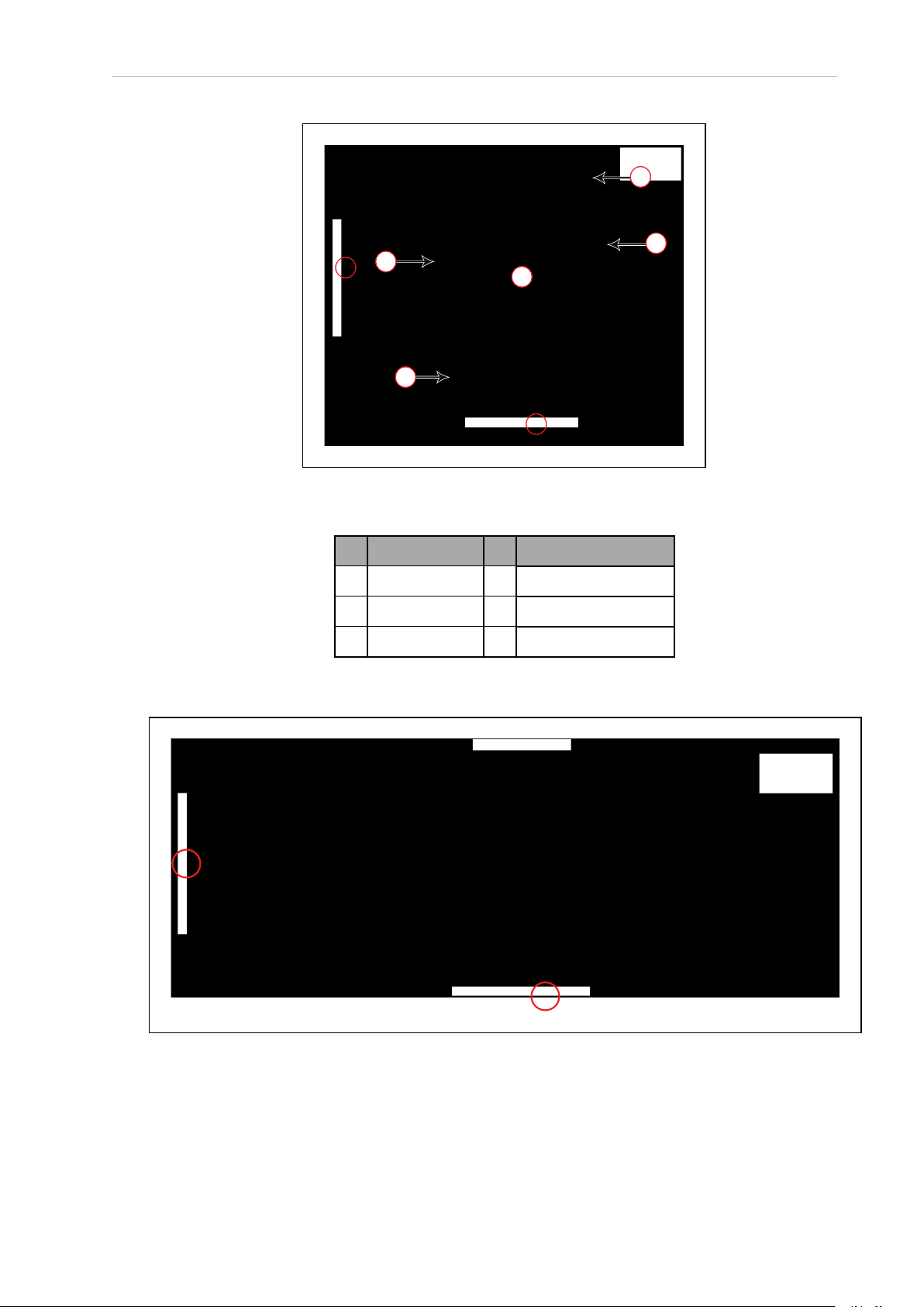
The HD-1500 has four E-Stop buttons, two on either side of the platform (a red push-lock button). The Operator Panel provides an additional E-Stop button (a red push-lock button on a yellow background). See the following figures.
Figure 2-4. E-Stop Button on the Platform
Figure 2-5. E-Stop Button on the Operator Panel
16 Mobile Robot HDSafety Manual 31500-100 RevA
Page 17

Chapter 2: Operational Safety
Use the User Safety Interface connection, located on the user access panel, to add E-Stop buttons to your payload structure, if required.
In the event of an emergency stop:
l
The AMR uses motor power to come to a controlled stop then engages its motor brakes
and removes power to its drive motors.
l
Indicator lights on the AMR, and the pendant (if attached) show the E-Stop state.
A user-initiated E-Stop differs from a laser-initiated protective stop (they both are category 1
stop). The latter occurs when one or both of the AMR's safety scanning laser detects an object
within its protected zone. In such cases, the AMR safely stops, and then resumes operation
after a delay of at least two seconds, and after confirming that its protected zone is clear of
obstacles.
An emegency stop initiated by pressing one of the E-Stop buttons, is a controlled stop function.
In this case, the power to the AMR motors remains on in order to achieve a controlled stop.
Once the controlled stop is achieved, the power to the motors is disconnected. If for any reason
the controlled stop function fails or does not function as expected, the power will still be disconnected to the motors. Activating an emergency stopby pressing one of the E-Stop buttons
requires manual deactivation of the E-Stop button, and manual reset of the AMR through the
ON button for the AMR to restart its operation. The AMR will not automatically recover from
an emergency stop initiated by pressing one of the E-Stop buttons on the AMR.
To use an E-Stop button:
1. Push firmly on the red button so that it latches.
2.
Follow your site-specific emergency and safety procedures.
If you need to move the AMR manually after correcting the emergency condition, press and
hold the brake release button and move the AMR. You can also use the pendant to drive the
AMR manually, if it is safe to do so. In order to use the pendant, you must first release the
E-Stop.
To enable the AMR's drive motors and put it back into service, follow the procedure described
in: Releasing an E-Stop on page 19.
Releasing the Brakes
In case of an emergency or abnormal situation, the AMR can be manually moved. However,
only qualified personnel who have read and understood this manual and the HD-1500 Plat-
form User's Manual (Cat. No. I645) should manually move the platform. The brakes on the drive
wheels can be released with the brake release button. This requires battery power, and an EStop must be pressed on the AMR.
NOTE: You should move the HD-1500 manually only when absolutely necessary during an emergency, for safety, or if it is lost or stuck. If you find that you
must frequently move the HD-1500, use MobilePlanner to reconfigure its route to
avoid problem areas.
31500-100 RevA Mobile Robot HDSafety Manual 17
Page 18
2.4 What to Do in an Emergency
!
!
!
WARNING: PERSONALINJURYORPROPERTYDAMAGERISK
Using the brake release button while the HD-1500 is positioned on a slope of
greater than 3% will cause the HD-1500 to roll down. You must not use the
brake release button to move the HD-1500 manually, when positioned on a
slope of greater than 3%, unless necessary precautions have been taken to prevent uncontrolled rolling of the HD-1500. The HD-1500 is not intended to be
operated on ramps or sloped surfaces.
CAUTION: PERSONALINJURYORPROPERTYDAMAGERISK
Pushing an HD-1500 requires significant effort and might cause personal
injury or property damage. Take appropriate care and follow all safety instructions.
WARNING: PINCHRISK
Take necessary precautions when moving an
AMRwithout its skins attached. The motor and
motor assemblies will be exposed when the side
skins are removed, exposing the potential pinch
points. Refer to the following figure.
The rear and top of the AMR also pose pinch
hazard when the rear skin and the top plate are
removed.
Figure 2-6. Side Skin Removed - Exposing Motor and Motor Assemblies
Application-specific attachments can affect an AMR's stability. All operators should know the
locations on the AMR (or its payload) where they can push safely without tipping the AMR
over or damaging its components. This should be as low as possible and near the center of
gravity.
18 Mobile Robot HDSafety Manual 31500-100 RevA
Page 19

Chapter 2: Operational Safety
!
!
OMRON recommends that you train personnel on the safe use of the brake release button, and
procedures for safely pushing an HD-1500.
CAUTION: PERSONALINJURYRISK
The pushing locations of the AMR are low. You must use safe pushing/
pulling practices when manually moving the AMR.
Releasing an E-Stop
This section describes how to release an E-Stop and bring the AMR back into service.
CAUTION: PERSONALINJURYORPROPERTYDAMAGERISK
If an AMR’s E-Stop is triggered, ensure that the cause of the E-Stop is resolved,
and all surrounding areas are clear before releasing the E-Stop.
To release an E-Stop:
1.
Make sure that all surrounding areas are clear before you release the E-Stop button so
that the AMR has room to maneuver.
2.
Rotate the E-Stop button in the direction of the arrows on the button and allow it to pop
up.
3.
After you release the E-Stop button, you must enable the motors manually by pressing
the green ON button on the operator panel.
After you enable the motors there is a delay of several seconds before the AMR can resume
operation.
NOTE: If you manually move the AMR while it is powered off, it may not be
able to determine its current location. Use the localization feature in MobilePlanner to localize the AMR.
Enabling motor power, either at the start-up or after an E-Stop release, must be done through a
manual action at the system, and only after the operator has confirmed that it is safe to return
the AMR to operation. Enabling the motor power must be an additional act after releasing an
E-Stop, and it is done by pressing the Operator Panel's On button.
31500-100 RevA Mobile Robot HDSafety Manual 19
Page 20
2.5 User's Responsibilities
!
!
!
!
2.5 User's Responsibilities
You are responsible for continuous safe use of the AMR.
WARNING: PERSONALINJURYORPROPERTYDAMAGERISK
Any modifications made to the AMR can lead to loss of safety or functionality
of the AMR. It is the end-user's responsibility to perform complete risk assessment after making any modifications to the AMR, and to confirm that all safety
features of the AMR are fully functional.
WARNING: PERSONALINJURYRISK
It is the end-user's responsibility to perform a task-based risk assessment and
to implement appropriate safety measures at the point of use of the AMR in
accordance with local regulations.
WARNING: PERSONALINJURYORPROPERTYDAMAGERISK
It is the end-user's responsibility to make sure that the AMR design and implementation complies with all local standards and legal requirements.
WARNING: PERSONALINJURYORPROPERTYDAMAGERISK
It is the end-user's responsibility to make sure that the AMR is operated within
its specifications, intended use, and intended environments.
Safe use of the AMR requires that you:
l
Read the installation and operation instructions, in addition to the HD-1500 Platform
User's Manual (Cat. No. I645), before using the AMR.
l Review, and understand the safety protections (E-Stops, safety laser stopping distances,
overhanging load, etc.) associated with your specific application and environment.
l
Make sure that the environment is suitable for safe operation of the AMR.
l
Make use of the Fleet Manager when two or more AMRs are used in the same environment, and are not confined to separate workspaces. See: Fleet Operations Workspace
Core User's Manual (Cat. No. I635).
l
Make sure that any person working with or near an AMR is trained, and has read the
HD-1500 Platform User's Manual (Cat. No. I645) for safe AMR operation.
l
Mechanically maintain and service AMRs for proper operation of all control and safety
functions.
20 Mobile Robot HDSafety Manual 31500-100 RevA
Page 21
Electrical Hazards
!
!
WARNING: ELECTROCUTIONRISK
The charging station has ACpower inside. Its covers are not interlocked. You
must disconnect the power prior to maintenance work.
WARNING: FIRE RISK, ELECTRICAL BURNRISK
The HD-1500 battery, and the charger outputs have high current. You must
take appropriate precautions to avoid potential short circuit.
l
Never access the interior of the platform with the charger attached.
l
Avoid shorting the battery terminals or connectors.
l
Do not use any charger or battery not supplied by OMRON. The charger shall only be
used to charge an HD-1500 battery.
l
The HD-1500 battery shall only be charged by an HD-1500 Charger.
Chapter 2: Operational Safety
l
If any liquid is spilled on the AMR, power off the AMR, clean up all possible liquid,
and allow the AMR to air dry thoroughly before restoring power.
Contact your OMRON representative if you suspect that liquid has penetrated the skins
or contaminated the AMR's interior.
l
Avoid liquid near the charging station, and the AMR.
l
Do not open the power supply box, electrician access box, or even the docking target
until you have read the appropriate sections of this user's guide, and performed appropriate Lock-Out, Tag-Out (LOTO) procedure. See: Lock-Out, Tag-Out Procedure on page
35.
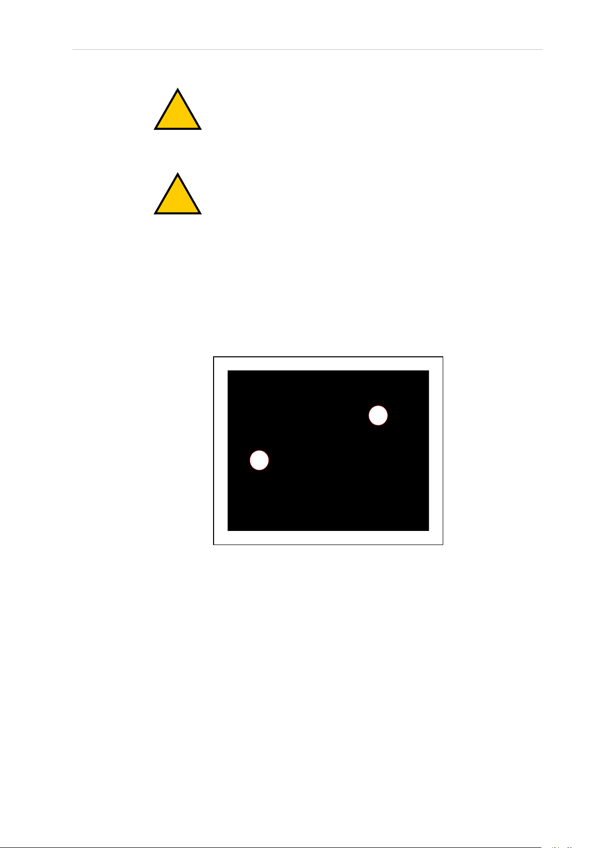
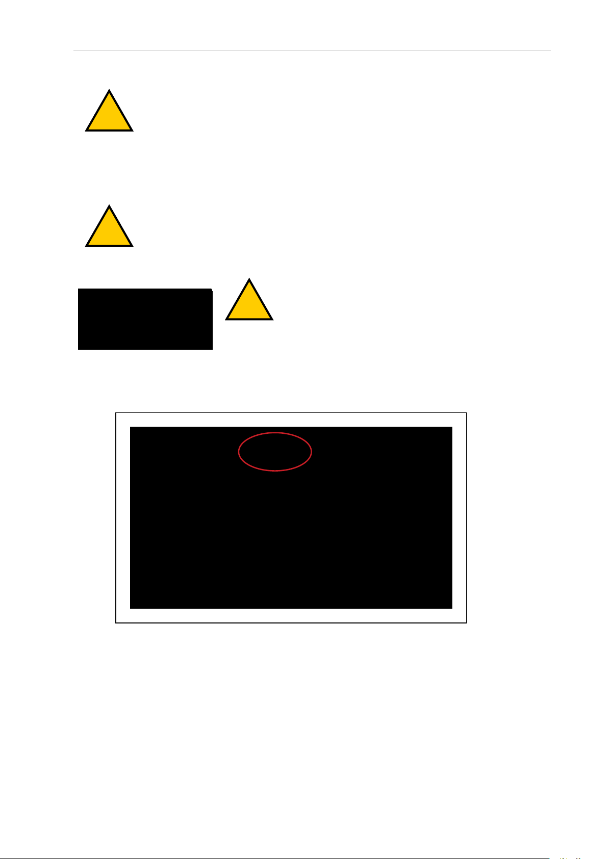
Magnetic Field Hazards
The rare-earth magnet embedded in the HD-1500 charging contacts create a strong magnetic
field. Persons with medical implants must not approach the HD-1500. See the following figure
for location of the charging contacts.
WARNING: MAGNETIC FIELD MEDICAL IMPLANT RISK
Magnetic fields can be hazardous if
you have a medical implant. Keep a
minimum of 30 cm away from the
HD-1500.
31500-100 RevA Mobile Robot HDSafety Manual 21
Page 22

2.5 User's Responsibilities
Burn Hazard
Figure 2-7. HD-1500 Charging Contacts Location
CAUTION: BURNRISK
The charging station and the charging contacts on both the docking target, and
the AMR can get hot during the operation. The operator must allow for cool
down prior to servicing.
CAUTION: BURNRISK
The AMR drive wheel motors can get extremely hot during the operation. The
operator must allow the drive wheel motors to cool down prior to performing
any maintenance work near or around them.
Qualification of Personnel
It is the end-user’s responsibility to ensure that all personnel who will work with or around
AMRs have attended an appropriate training, and have a working knowledge of the system.
The user must provide the necessary additional training for all personnel who will be working
with the system.
As described in this guide, and the HD-1500 Platform User's Manual (Cat. No. I645), you should
allow only skilled persons or instructed persons to do certain procedures:
l
Skilled persons have technical knowledge or sufficient experience to enable them to
avoid either electrical or mechanical dangers.
l
Instructed persons are adequately advised or supervised by skilled persons to enable
them to avoid either electrical or mechanical dangers.
For example, replacing a battery is a task for a skilled person, while an instructed person can
complete the task of charging a battery.
All personnel must observe industry-prescribed safety practices during the installation, operation, and testing of all electrically-powered equipment.
22 Mobile Robot HDSafety Manual 31500-100 RevA
Page 23

Chapter 2: Operational Safety
!
IMPORTANT: Before working with the AMR, every person must confirm that
they:
l
Have the necessary qualifications and training.
l
Have received the guides (both this user’s guide, and the HD-1500 Platform User's
Manual (Cat. No. I645)).
l
Have read the guides.
l
Understand the guides.
l
Will work in the manner specified by the guides.
Payload Movement and Transfer
A typical AMR application uses a payload structure to transport objects within a facility. For
example, the AMR might pick up and carry a crate of engine parts from one conveyor belt
then deliver it to another conveyor belt.
WARNING: PERSONALINJURYORPROPERTYDAMAGERISK
It is the end user's responsibility to ensure that the payload is properly secured
to the HD-1500 platform, and that the payload does not experience any shifting
during movement of the AMR. For example, when transporting containers of
liquids, the operator must take necessary precautions to prevent sloshing of the
fluid as it affects the stability of the AMR.
Intentional movement of the payload structure (such as conveyor or AMR arm) during the
AMR movement is prohibited. It is the end-user's responsibility to design an appropriate interlock to prevent this.
During movement and transfer, you must actively monitor and confirm the transfer operation
to make sure that it completes successfully. If any operation fails, a fail-safe interlock must trigger an AMR E-Stop condition. An E-Stop condition prevents the AMR from moving until you
resolve the problem and confirm that it is safe to restart operations.
Your facility should provide such fail-safe interlocks between the AMR and any facility equipment with which it interfaces. After you attach your payload to the AMR, verify the correct
operation of the fail-safe as part of your risk assessment.
Configurable Warning Buzzer
The HD-1500 has a configurable warning buzzer. You should configure this buzzer as appropriate for the facility in which the AMR will be operating. The warning buzzer is configured
with MobilePlanner.
The buzzer must be audible above the ambient noise of the environment that the HD-1500
operates in. In environments with higher levels of noise, you may need to supply and install
an additional warning buzzer to an appropriate location on the payload structure.
You can also configure the buzzer to activate in other specific situations, or to operate continuously whenever the AMR moves.
31500-100 RevA Mobile Robot HDSafety Manual 23
Page 24

2.5 User's Responsibilities
!
l
Any time the AMR moves at a linear speed below 20 mm/s, or a rotational speed of less
than 3 deg/sec for longer than 2 seconds. This is done to alert the users of a very slowly
moving AMR which is not configured with hardware-based safety zones by default.
NOTE: The software-based obstacle protection is used regardless of the
AMR speed.
l
For 2 seconds prior to starting motion any time it has stopped moving for at least 10
seconds. This includes the first motion after start-up.
l
For 2 seconds when an emergency stop or a protective stop from hardware-based safety
zones is triggered.
NOTE: These parameters are only available with the Fleet Operations Workspace 1.1 and later.
CAUTION: PERSONALINJURYRISK
Changing buzzer parameter values might make the AMR unsafe and affect its
compliance to safety standards. Refer to the applicable safety standards for
your locale before you change any parameter values.
Speakers
The HD-1500 is equipped with two speakers, located at the front of the AMR.
When speakers are used as a means of notifying personnel of an approaching AMR, you must
routinely verify that they are still functioning normally. Verify that the speakers are audible,
and the sound level is at the same level as needed during the operation.
Mechanical Brakes
Perform annual inspection of the mechanical brakes for proper function. Follow these steps to
verify that the mechanical brakes engage and disengage properly.
Before you begin, make sure it is safe to manually move the AMR to an open area with level
floor.
1.
Connect the pendant to the AMR, and drive forward approximately 2 m in order to
align the casters in the direction of motion.
2.
Next, release the three-position enabling device to ensure that the AMR is in protective
stop mode.
3.
Then, press and hold the brake release button, and push the AMR straight forward. One
or two people should be able to push an unloaded or lightly loaded platform. For a
heavily loaded platform, you may need more people.
You will hear a click sound when the brake release button is pressed. The AMR should
roll smoothly at this point. contact your OMRON representative if the AMR does not
move.
4.
Next, release the brake release button and then try to push the AMR forward with the
24 Mobile Robot HDSafety Manual 31500-100 RevA
Page 25

Chapter 2: Operational Safety
!
same amount of force used in the last step. The AMR should not move.
5.
If the AMR moves, stop using the AMR, and contact your OMRON representative.
Fleet Management
When two or more AMRs operate in the same workspace they may not be able to accurately
detect each other or to precisely determine each other's dimensions. This is due to the fact that
the AMRs' scanning lasers are positioned inside of the platform perimeter. There are channels
along the front, rear, and sides of the platform that allow a clear line of sight for the scanning
laser. When two similar AMRs approach each other their scanning lasers will detect the inner
surface of that channel and not the outer perimeter of the other AMR. Operating an HD-1500
with any of its skins detached will worsen this effect. Typically this will not present a problem,
however, in close proximity each AMR will plan its motion more accurately with information
from the Fleet Manager about the position of the other AMR.
To manage and administer multiple AMRs in the same workspace, you must use a EM2100
appliance configured as a Fleet Manager, running the Fleet Operations Workspace (FLOW) software.
The Fleet Manager controls AMRs over a wireless network (WiFi), improving the efficiency of
AMR operations by sharing the information between all AMRs in the fleet. The shared information includes: improving the efficiency of AMR operations.
l
Dynamic position and heading (velocity and direction of travel) of the AMR.
l
AMR size (including payload structure).
l
Path planning information (the individual AMR's intended route).
CAUTION: PERSONALINJURYORPROPERTYDAMAGERISK
Improper path planning can result in personal injury or property damage.
IMPORTANT: Do not leave an AMR that is not localized, not connected to the
Enterprise Manager, or not powered on in a location that can be accessed by
other AMRs.
AMRs factor this data into their path planning.
IMPORTANT: Fleet Manager is not an interlocked method of collision prevention. It is your responsibility to implement interlocked methods of collision
prevention where necessary.
For operational redundancy and fail-over you can add a second EM2100. See the Fleet Oper-
ations Workspace Core User's Manual (Cat. No. I635) for more information.
31500-100 RevA Mobile Robot HDSafety Manual 25
Page 26

2.6 Risk Assessment
!
Other Hazards
NOTE: Hazards specific to maintenance are covered in Safety Considerations
when Performing Maintenance on page 33, and Safety Measures Prior and After
Maintenance on page 35.
2.6 Risk Assessment
Safety standards in many countries require appropriate safety equipment to be installed as
part of the system. Safeguards must comply with all applicable local and national standards
for the location where the AMR is installed.
WARNING: It is the end-user's responsibility to perform a task-based risk
assessment, and to implement appropriate safety measures at the point of use
of the AMR in accordance with the local regulations.
Exposure
Based on the risk assessment performed by OMRON, the hazards associated with exposure to
the AMR are minimal. However, these significantly rely on the awareness and training of the
personnel around the AMR. Along with common sense, the following should be observed and
practiced in order to avoid the minimal risks associated with exposure to the AMR.
l
Do not ride on the AMR. Riding on the AMR or staying in the vicinity of the AMR for
long periods (when ON or while charging) will expose you to the magnetic fields generated by the AMR.
l
The users must be aware of the HD-1500 unprotected zones (operating hazard zones),
and keep a safe distance from the AMR to prevent personal injury.
Severity of Injury
The severity of injury depends on the type of payload and how the payload is integrated with
the HD-1500. The severity of injury increases with the mass of the payload. Follow all industrial safety practices, such as use of steel-toe shoes around the AMR, and adding additional
protection like side lasers, etc. depending on how the AMR is configured, to reduce any workrelated injuries.
Obstacle Avoidance
The AMR will avoid obstacles unless modified or the safety systems are intentionally defeated.
The AMR has a dual-channel, safety-rated laser to avoid obstacles. OMRON offers side lasers
option that enables the AMR to avoid obstacles and persons.
IMPORTANT: When the pendant is connected to the AMR, the operator must
maintain control of the pendant and AMR at all times.
The HDPlatforms are fully-autonomous AMRs that, once configured, work around people in
industrial settings with no intervention needed. Risks associated with integrating the AMR in
the industry can be avoided, with a few basic steps.
26 Mobile Robot HDSafety Manual 31500-100 RevA
Page 27

l
!
Only trained personnel, who understand what the AMR does, should be in the vicinity
of the AMR.
l
Audio and visual alarms are built into the AMR. Do not modify these unless necessary.
l
Additional safety measures may be implemented as deemed necessary by the integrator
after risk assessment is completed.
Safety System Behavior
The standard control system is fully-hardened to all EMI influences. In addition, software monitors and controls all dual redundancy safety-rated features for certainty.
2.7 Environment
General Environmental Conditions
Make sure that the HD-1500's operating environment remains safe for the HD-1500.
Chapter 2: Operational Safety
WARNING: PERSONALINJURYORPROPERTYDAMAGERISK
An AMR can be unsafe if operated under environmental conditions other than
those specified in this manual.
l
Environmental Hazards—These are areas where it is unsafe for the HD-1500 to operate.
Provide physical barriers that the HD-1500 can detect accurately with its scanning laser
so that it does not attempt to drive near the hazard. Be aware that in addition to being
easily detectable, a barrier must be strong enough to resist a fully-loaded HD-1500 traveling at its maximum speed.
l
Restricted Zones—These are zones of inadequate clearance which cannot be protected
by the AMR detection devices. Only authorized persons are permitted to enter. You can
use map features such as forbidden areas to keep HD-1500s within their designated
area of operation. See the Fleet Operations Workspace Core User's Manual (Cat. No. I635) for
information about editing your workspace map.
l
Operating Hazard Zones—These operating zones are areas of inadequate clearance
(less than 500 mm) between the sides of the AMR (or front/rear of the AMR) and an
obstacle such as a wall that would not leave sufficient room for a person to escape and
avoid getting crushed between the AMR and the obstacle. It can also be an area which
cannot be protected by the AMR detection devices. These areas shall be clearly indicated
by suitable signs or preferably floor markings. In this operating hazard zone, the AMR
speed shall be in accordance with ISO 3691-4, and shall emit additional audible or
visual warnings.
l
Confined Zones—These are zones of inadequate clearance, and where the AMR detection devices may be omitted, at any speed. The confined zones shall be marked, and be
enclosed with fixed guards that are at least 2.1 m high.
l
Load Transfer Stations—These are the designated locations for load transfer. When the
load transfer stations are outside the restricted or confined zones, these stations shall be
designed to prevent personal injury by the rigid parts of the AMR or its payload. These
31500-100 RevA Mobile Robot HDSafety Manual 27
Page 28

2.7 Environment
load transfer stations shall be designated as operating hazard zones as defined in this
section of the manual.
Although the HD-1500's software provides the option of using the map features to keep the
HD-1500 within its designated workspace, you must always install physical barriers where
there is a risk of property damage or personal hazard.
Public Access
The HD-1500 is designed to operate in indoor industrial environments, and in presence of
trained personnel. You must deploy it only in applications where you anticipate and mitigate
potential risks to personnel and equipment.
OMRON intends for the HD-1500 to be used in controlled areas for which a risk assessment
has been conducted. OMRON does not intend the HD-1500 to be used in, for example, areas
open to general public access.
Operating Clearances
This section provides information regarding the side clearances, rotation clearances, and the
docking clearances when operating.
Side Clearances
The HD-1500 is designed to operate in environments that contain doors, passageways, or other
constrained areas that are wide enough for it to traverse.
However, you must maintain adequate side clearance (free space) on both sides of the AMR so
that it cannot trap a person against a wall or other fixed object. Consult the applicable
Autonomous Vehicle and Robotics operating standards for your locale.
An AMR must often maneuver close to machinery, conveyors, or other fixed objects. In such
cases, operating standards usually allow an exception to side clearance requirements.
For information about software parameters that you can use to control the HD-1500's front and
side clearance zones, see: Fleet Operations Workspace Core User's Manual (Cat. No. I635).
Rotation Clearances
The HD-1500 travels in forward and backward directions. To change its direction, the HD1500 rotates on its center of rotation (turns in place). The HD-1500 has a full safety coverage of
360°, and therefore, obstacles will trigger a safety system event when the AMR rotates.
The HD-1500's Light Discs as well as its front and back light strips display a distinct turn signal pattern when it rotates.
Docking Clearances
You should set a 2.5 m distance between the docking target (the goal defined in the map) and
the dock goal position of the AMR. This distance provides sufficient room for the AMR to
align with the docking target when docking. See: Figure 2-8. and Figure 2-9.
When docked, the distance between the AMR and the docking target is less than 500 mm, and
therefore, this area is considered to be a hazard zone.
28 Mobile Robot HDSafety Manual 31500-100 RevA
Page 29

Chapter 2: Operational Safety
A
B
1300
Figure 2-8. Goal Position - Measured From the Center of the Docking Target to the Center of
the HD-1500, (A) Docking Target, and (B) HD-1500
Figure 2-9. Goal Position - Measured from the Front Face of the HD-1500 to the Charging Paddle
31500-100 RevA Mobile Robot HDSafety Manual 29
Page 30

2.7 Environment
A
B
Figure 2-10. HD-1500 Docked with the Docking Target, (A) 500 mm, and (B) Floor Marking
Obstacles
Before an AMR enters a high-traffic area, you must take appropriate precautions to alert people
working in those areas:
l
The HD-1500 provides programmable warning features such as a warning buzzer,
speech synthesis, and warning indicator lights.
l
The user access panel provides user ports that enable you to add warning indicators to
your payload structure.
If high-traffic areas include other moving vehicles such as fork-lift trucks or autonomous moving machines, consider adjusting the AMR's operating parameters to reduce the risk of a collision. You can do this by:
l
Editing the workspace map to include features that restrict the AMR's operation in specific areas, such as preferred lines, resisted areas, and movement parameter sectors to
reduce speed.
l
Editing the AMR's configuration to affect its behavior in all locations, such as restricting
its maximum speed.
Additional Information: For more information, see: Fleet Operations Workspace
Core User's Manual (Cat. No. I635).
IMPORTANT: The safety scanning laser password, required to make any safetycritical changes to the safety scanning laser configuration, can be changed by the
user. The user can change the password to limit access by unauthorized users.
For instructions on how to change the password, refer to Safety Laser Scanner
OS32C Series User's Manual (Cat. No. Z296-E1).
30 Mobile Robot HDSafety Manual 31500-100 RevA
Page 31

2.8 Intended and Non-intended Use
Intended Use
The intended use of the HD-1500 is to navigate autonomously in indoor industrial environments, and reach the specific locations it is deployed to. The HD-1500 is capable of transferring a payload of up to 1500 kg. You must ensure that the payload structure does not extend
beyond the HD-1500's footprint. The center of gravity (CG) of the combined mass of the payload structure (including all onboard tooling and loads being transported) must be within the
specified CG limits. The CG limits must be observed to ensure stability when loading and
unloading the AMR. See: Center of Gravity (CG) on page 60.
OMRON does not provide the method of loading the payload onto or off the HD-1500. It is the
end user's responsibility to perform a complete task-based risk assessment in accordance with
EN ISO 12100, and ensure safe transfer of the payload. The HD-1500 shall be commissioned as
instructed in this manual.
The HD-1500 is designed to operate in indoor industrial environments. This includes structured or semi-structured workplaces such as warehouses, distribution and logistics facilities
where general public access is restricted. The environment must be flat and level (maximum of
3% grade), free of clutter and debris, and with wide enough doorways to be navigable by an
HD-1500. The HD-1500 can operate at its maximum speed through a 2200 mm opening, and
will traverse at a slower speed through a 2100 mm opening.
Chapter 2: Operational Safety
DANGER: PERSONALINJURYRISK
Improper operation of the AMR on inclined floors that do not comply with the
applicable operating specifications can result in the AMR tipping over, and
consequently a serious personal injury.
The following guidelines apply:
l
Floor—Clean and dry floors that you sweep regularly and routinely keep free of debris,
dust, and liquids.
l
Temperature—5 to 40°C with a humidity range of 5% to 95%, non-condensing. Operating the HD-1500 at high or low ambient temperatures (particularly with a full payload and high speeds) can cause the battery to exceed its operating temperature limits.
l
Altitude—Up to 2,000 m.
The HD-1500 has an ingress protection rating of IP20. Do not expose the HD-1500 to liquid.
Non-Intended Use
When deploying an AMR, anticipate potential risks to personnel and equipment. OMRON
intends the HD-1500 for use in a carefully controlled and managed environment with restricted access granted only to authorized and trained personnel.
You must conduct a risk analysis before you deploy the HD-1500 in a new environment.
Application of the HD-1500 in environments other than those described in the preceding paragraph generally requires additional safety measures.
OMRON does not intend the HD-1500 for deployment in environments that contain:
31500-100 RevA Mobile Robot HDSafety Manual 31
Page 32

2.8 Intended and Non-intended Use
l
Hazardous (explosive or corrosive) atmospheres.
l
Ionizing radiation.
l
Intense interference light, such as direct sunlight.
l
Extreme heat or humidity.
l
Inclined floors or ramps.
l
Soft surfaces such as carpet.
l Floors that are damp or have any standing water.
IMPORTANT: The HD-1500 is not intended to operate in a damp/wet
environment where it will be exposed to liquid or liquid ingress.
In addition, OMRON does not intend the HD-1500 for deployment in the following environments:
l
Outdoor or uncontrolled areas without risk analysis.
l
Environments with general public access.
l
Life-support systems.
l
Residential areas.
l
Non-stationary areas, including moving floors or any type of land vehicle, watercraft, or
aircraft. (HD-1500 navigation is assisted by sensing embedded in the AMR Controller
that requires a stationary environment to be effective.).
IMPORTANT: You must always observe the instructions for operation, installation, and maintenance provided in this guide and in the HD-1500 Platform
User's Manual (Cat. No. I645).
Other non-intended use of the HD-1500 includes:
l
Towing applications.
l
Personnel riding vehicle.
IMPORTANT: The HD-1500 is not intended to be used with a battery that is not
supplied by OMRON. Additionally, it is not intended to be charged by any
charger other than the OMRON charging station.
Non-intended use of an HD-1500 can:
l
Cause injury to personnel.
l
Damage the HD-1500 or other equipment.
l
Reduce reliability and performance.
If there is any doubt concerning the application, contact your OMRON representative for support.
32 Mobile Robot HDSafety Manual 31500-100 RevA
Page 33

Chapter 2: Operational Safety
!
HD-1500 Platform Modifications
OMRON recognizes that end-users or integrators make modifications to the HD-1500 to adapt
it to a specific application. When doing so, make sure that:
l
You use the User Safety Interface connection located on the user access panel, to include
appropriate safety devices into the HD-1500's integrated safety systems.
l
The modification causes no hazardous sharp edges, corners, or protrusions and does
not extend further than the HD-1500 footprint. If the modification causes extension beyond the HD-1500 footprint, you must contact your OMRON representative for assistance with modifying the safety zones.
l
The final design of the HD-1500 meets all relevant local and national safety standards,
and requirements for the new intended use.
l
There is no reduction in functionality.
l
All safety features (such as lasers and brakes) are functional and operate within the specifications determined by local product safety standards for AMRs.
l
You add additional safety features if determined to be necessary based on risk assessment results.
l
You perform proper risk assessment in accordance with EN ISO 12100, and identify any
risks associated with the modification made to the HD-1500 platform. It is the enduser's responsibility to ensure that these risks are properly mitigated/eliminated, so the
AMR does not cause personal injury or property damage.
2.9 Safety Considerations when Performing Maintenance
This section describes important safety considerations when maintaining your AMR.
Prior to performing maintenance work on your AMR, you should make sure that the area you
will be performing maintenance in, can not be interrupted by other AMRs and is adequately
protected.
IMPORTANT: Only skilled or instructed persons, as defined in this manual,
should perform the procedures and replacement of parts covered in this section.
WARNING: PERSONALINJURYORPROPERTYDAMAGERISK
When working near the encoder cables, take care not to disconnect or damage
them. Improper connection or disconnection of encoder cables may result in
erratic motion of the AMR during operation. The AMR might rotate uncontrollably during loss of encoder signals.
31500-100 RevA Mobile Robot HDSafety Manual 33
Page 34

2.9 Safety Considerations when Performing Maintenance
!
Electrical Hazards
WARNING: ELECTROCUTIONRISK
During maintenance and repair, you must turn off power to the charging station. Remove and lock up the power cord along with all other electrical inputs
to prevent unauthorized third parties from turning on power. The access covers on the charging station are not interlocked.
WARNING: ELECTROCUTIONRISK
There are no user-serviceable parts inside the charging station. Do not remove
the covers of the charging station. There is high voltage inside, and the covers
are not interlocked.
WARNING: FIRE RISK, ELECTRICAL BURNRISK
The HD-1500 battery, and the charger outputs have high current. You must
take appropriate precautions to avoid potential short circuit.
Electrical Hazard Precautions
l
There are no user-serviceable parts inside of the battery. Do not open the battery.
l
Do not use any charger not supplied by OMRON.
l
If the AMR comes into contact with any liquid:
1.
Power off the AMR.
2.
Clean off as much liquid as is possible.
3.
Allow the AMR to air dry thoroughly before restoring power.
4.
Contact your OMRON representative if you suspect that liquid has penetrated
the skins or contaminated the AMR's interior.
Burn Hazard
CAUTION: BURNRISK
The charging station and the charging contacts on both the docking target, and
the AMR can get hot during the operation. The operator must allow for cool
down prior to servicing.
CAUTION: BURNRISK
The AMR drive wheel motors can get extremely hot during the operation. The
operator must allow the drive wheel motors to cool down prior to performing
any maintenance work near or around them.
34 Mobile Robot HDSafety Manual 31500-100 RevA
Page 35

ESD Hazards
CAUTION: PROPERTYDAMAGE RISK
The electrical charge accumulated on the HD-1500's skins does not have a path
to ground, and therefore can not discharge. This can be hazardous to electrostatic sensitive devices. Users must keep the electrostatic sensitive devices at
least 30 cm away from the AMR skins.
2.10 Safety Measures Prior and After Maintenance
Prior to performing maintenance work (safety inspection, cleaning, removing parts, installing
parts, etc.), following safety measures must be taken:
l
Ensure that the AMR has come to a complete stop, by pressing an E-Stop button.
l
Power off the AMR by pressing the OFF button on the Operator Panel.
Once maintenance work has completed, and the AMR is ready for use, press the ON button on
the Operator Panel.
Chapter 2: Operational Safety
Lock-Out, Tag-Out Procedure
You must complete the appropriate Lock-Out, Tag-Out (LOTO) procedure prior to any maintenance work on the charging station or the AMR.
The following sections describe the LOTO procedure for the AMR, and the charging station.
LOTO Procedure for the AMR
Follow this LOTO procedure for the AMR:
1.
Prepare the AMR for shutdown. You must make sure that the AMR is in a safe location,
and that there are no hazards near it. There must be sufficient clearance around the
AMR to allow for safe maintenance work.
2.
Press an E-Stop button.
3.
Shutdown the AMR by pressing the OFF button on the Operator Panel.
4.
Turn the AMRmain disconnect switch to OFF position (horizontal position). The
AMRmain disconnect switch is located on the Operator Panel.
You must lock the main disconnect switch, and tag according to your facility requirement and regulations.
31500-100 RevA Mobile Robot HDSafety Manual 35
Page 36

2.10 Safety Measures Prior and After Maintenance
!
Figure 2-11. AMR Main Disconnect Switch Located on the Operator Panel
5.
Each motor controller is equipped with a capacitor that stores energy. You must check
and make sure that the voltage left is less than 7 V. Probe the appropriate connector
pins on the module displayed in Figure 2-12. using a digital multimeter. Prob the back
of the pin 4 (positive), and pin 3 (negative) as shown in Figure 2-13.
WARNING: ELECTRICALSHOCKRISK
Do not perform maintenance work on the AMR until the measured
voltage is below 7 V.
Figure 2-12. Location of the Module to be Probed
36 Mobile Robot HDSafety Manual 31500-100 RevA
Page 37

Chapter 2: Operational Safety
A
B
AA
B
Figure 2-13. Module Connector Configuration - Viewed from the Rear, (A) Pin 3 (Negative),
and (B) Pin 4 (Positive)
6.
Continuously check and verify that the AMR is de-energized by pressing the ON/OFF
button on the Operator Panel.
LOTO Procedure for the Charging Station
Follow this LOTO procedure for the charging station:
1.
Turn the power off. You can do this by switching the main disconnect switch, located
on the electrician access box, to OFF position.
Figure 2-14. Main Disconnect Switch on the Electrician Access Box, (A) ON Position, and
(B) OFF Position
31500-100 RevA Mobile Robot HDSafety Manual 37
Page 38

2.10 Safety Measures Prior and After Maintenance
Figure 2-15. Main Disconnect Switch Placed in OFF Position
2.
Lock the main disconnect switch as displayed in the following figure. The type of lock
used depends on your needs, and your facility LOTOrequirements. You may also add
your name to the lock, or have multiple names on the lock. This lets other users know
who has locked the power supply box in case they must get in touch with that person.
Figure 2-16. Main Disconnect Switch Locked
3.
Verify that the power is off. You can do this by checking the LED indicators, located on
the power supply box. When there is no power going through the power supply box, the
38 Mobile Robot HDSafety Manual 31500-100 RevA
Page 39

blue LED is off.
Chapter 2: Operational Safety
2.11 Safety Inspection
Safety and Warning Devices
Perform inspections of the following safety and warning devices for proper function.
The E-Stop buttons and the mechanical brakes must be inspected annually. The speakers must
be inspected as needed. The rest of the warning devices listed in this section must be inspected
weekly.
Flashing Light
Each AMR must have a readily visible flashing light, to serve as a warning whenever the
AMR is ready to move or is moving. The exact nature of this light will vary depending on the
design of the payload structure. For more information refer to HD-1500 Platform User's Manual
(Cat. No. I645).
Light Discs
Check the light discs on each side of the AMR for proper function. Refer to HD-1500 Platform
User's Manual (Cat. No. I645) for more information.
Figure 2-17. Blue LED Off
Front and Back Lights
Check the front and back lights of the AMR for proper function. For more information refer to
HD-1500 Platform User's Manual (Cat. No. I645).
31500-100 RevA Mobile Robot HDSafety Manual 39
Page 40

2.11 Safety Inspection
Buzzer
Check the warning buzzer for proper function. To comply with applicable standards, it is
important that the buzzer be audible in all operating conditions and environments. The buzzer
must exceed the ambient noise at the end use application. See also: Configurable Warning
Buzzer on page 23.
Speakers
When the speakers are used as a means of notifying personnel of an approaching AMR, you
must routinely verify that they are still functioning normally. Verify that the speakers are audible, and the sound level is at the same level as needed during the operation.
E-Stop Buttons
Inspect the E-Stop buttons for any sign of physical damage, and check for proper function.
Mechanical Brakes
Check the AMR mechanical brakes at least once a year, and make sure that the mechanical
brakes properly engage and disengage. For instructions on how to perform the inspection, refer
to the HD-1500 Platform User's Manual (Cat. No. I645).
Warning Labels
The only warning labels that are shipped with the HD-1500, unattached to the platform, are
the No Riding labels. All other labels are installed in the factory.
For information on where to attach the No Riding labels, refer to the HD-1500 Platform User's
Manual (Cat. No. I645).
Any additional safety labels for the payload structure or specific to the end-use application
shall be evaluated by the user as part of the risk assessment.
40 Mobile Robot HDSafety Manual 31500-100 RevA
Page 41

Chapter 2: Operational Safety
2.12 Protective Stops Initiated by AMR Safety Lasers
Under certain conditions, the AMR safety systems might cause a protective stop.
For example, an AMR reacts to obstacles in its path by slowing and, if necessary, stopping
safely. It then either plans a new path around the obstacle or (if the obstacle has moved)
resumes its original path. The safety lasers initiate a protective stop any time they detect
unavoidable obstacles in the AMR's path.
During the protective stop, the AMR decelerates to a stop at the maximum allowed rate. It then
removes power to its motors and engages the brakes.
NOTE: A protective stop initiated by an intrusion into a safety laser's protection
field differs from pressing an E-Stop button. After you press an E-Stop button,
you must first resolve the problem and then manually resume AMR operation.
See: What to Do in an Emergency on page 16.
Other circumstances might cause a protective stop, such as:
l
User-supplied sensors connected to the Safety Controller.
After the AMR comes to a complete protective stop caused by laser protection zone intrusion,
it waits a minimum of two seconds before it resumes operation. No user intervention is necessary and the AMR does the following:
1.
Verifies that there is adequate space to maneuver.
2.
Plans a local path deviation around the obstacle and resumes its operation.
This may cause the AMR to turn around, and move in a different direction. If no such path is
available, the AMR fails the current job, and waits for the Fleet Manager to assign a new job.
31500-100 RevA Mobile Robot HDSafety Manual 41
Page 42

2.13 Safety System Overspeed Faults
2.13 Safety System Overspeed Faults
The HD-1500 has an independent safety system that uses a Machine Automation Controller
(Safety Controller) to redundantly monitor its velocity. This device makes sure that the AMR
always operates within the speed limits.
If the AMR operates outside the specified velocity limit, its Safety Controller reports a Channel
1 or Channel 2 system fault to its operating firmware and begins an emergency stop (E-Stop)
sequence. The fault causes the AMR's motion controllers to execute a controlled stop (stop category 1).
If motion is already disabled (for example, an E-Stop button is engaged) and you override the
brake release, the safety system cannot stop the AMR. This is because power to the drive
motors is already disabled. After you resolve the error condition, the safety system stops reporting the safety fault to the motion controllers. At this point the safety system allows for the normal start-up process to begin but it does not automatically restart the AMR's operations.
Additional Information: Motion control configuration parameters in the ARAM
software (such as AbsoluteMaxTransVel parameter) limit the maximum allowable
velocities. Use MobilePlanner to modify the value of these parameters. See: Fleet
Operations Workspace Core User's Manual (Cat. No. I635).
When the HD-1500 protective stop is engaged, Polo commands a controlled stop at the highest
deceleration allowed. During the deceleration process, the Safety Controller continuously monitors the deceleration. If the AMR is not able to stop quickly enough, the Safety Controller disables the drive motors and engages the mechanical motor brakes in order to stop the AMR.
The motor brakes are powerful enough to stop a fully loaded HD-1500 traveling at its top
speed. However, engaging the mechanical motor brakes to stop the AMR is not a typical function. In the unlikely event that this occurs, you receive an error message in MobilePlanner, and
at the Operator Panel, which should not be ignored. This error can occur if:
l
the HD-1500 software fails to command a controlled stop (for any reason).
l
the floor is excessively slippery, and does not provide good traction.
l
the AMR is traveling down a slope steeper than its specified capability.
There may be other reasons for why this error occurs. A single occurrence of this error may not
cause a serious problem, however, repeated occurrence of this error should be investigated. If
this error occurs multiple times a day, contact your OMRON representative for support.
The use of the mechanical motor breaks to stop the AMR too many times will reduce the effectiveness of the motor brakes. This increases the distance required for the AMR to come to a full
stop.
If this error happens enough, MobilePlanner will present a stronger warning after each occurrence. If the problem is not resolved, the AMR may stop operating in order to prevent the use
of the potentially degraded brakes. Generally the degradation of the motor brakes requires hundreds of occurrences.
2.14 Laser Safety
The safety scanning lasers, optional side lasers, and Low Lasers are all Class 1 lasers. The
Class 1 laser, which is an invisible laser radiation, is safe under all conditions of normal use.
42 Mobile Robot HDSafety Manual 31500-100 RevA
Page 43

Chapter 2: Operational Safety
However, the maximum permissible exposure cannot be exceeded when viewing the laser
with the naked eye. OMRON recommends that you avoid long-term viewing of the laser.
31500-100 RevA Mobile Robot HDSafety Manual 43
Page 44

2.15 Interlock Switches
2.15 Interlock Switches
The HD-1500 is equipped with the interlock switches located on the battery door, and the
AMR side skins. The interlock switches continuously monitor and ensure that the battery door,
and the side skins are properly attached to the platform. This is to ensure that the battery compartment as well as the electronics bay enclosure are isolated, and protected from unauthorized/unsafe access. If the battery door, or any of the side skins opens or get removed, the
interlock switches disable the AMR's motion and disable power to the main bus bars.
CAUTION: BURNRISK
Do not touch the AMR drive wheel motors when the side skins are removed,
as the drive wheel motors can get extremely hot during the operation. You
must allow sufficient time for the drive wheel motors to cool down prior to
coming into contact with them.
Figure 2-18. Location of the Interlock Switch on the Electronics Bay Access Door Frame
44 Mobile Robot HDSafety Manual 31500-100 RevA
Page 45

Chapter 2: Operational Safety
!
Figure 2-19. Location of the Interlock Switch on the Battery Door Frame
To restore power to the main bus bars, you must:
l
Re-install the removed skin, or
l
If the battery door was opened, close the battery door.
Once the above is done, the AMR will return to its normal operating mode.
IMPORTANT: If you remove the side skins or open the battery door while the
HD-1500 is docked, and is charging its battery, the charging will stop. Once the
removed skin is re-installed or the battery door properly closed, the charging will
not re-engage automatically. The AMR must repeat the normal docking process
for autonomous charging, and re-start charging.
WARNING: ELECTRICAL SHOCKRISK, FIRE RISK, BURNRISK
The interlock switches shall not be defeated or bypassed as this would energize
the AMR, and expose the user to potential electrical hazards.
2.16 Battery Safety
Effective April 1, 2016, IATA regulations (UN 3480, PI 965) require that air-shipped lithium ion
batteries must be transported at a state of charge not exceeding 30%. To avoid total discharge,
fully charge the battery immediately upon receipt. (The battery might arrive fully charged if it
is not shipped by air.)
NOTE: After receiving the battery, check its state of charge by pressing and holding in the push-button on the battery indicator. If the battery is in a low charge
state, you must immediately charge to a full charge to avoid discharging the
31500-100 RevA Mobile Robot HDSafety Manual 45
Page 46

2.16 Battery Safety
A
B
D
D
C
C
battery below a usable state, which would require battery replacement. For
information on the battery indicator, refer to the HD-1500 Platform User's Manual
(Cat. No. I645).
Battery Safety Precautions
This section provides safety information and precautions when storing, transporting, and
removing/installing the battery.
Storage
Store the batteries within the following temperature range:
l -20 to 35°C, 5-95% RH non-condensing
For transportation of up to 2 weeks, the manufacturer recommends:
l -20 to 60°C, 5-95% RH non-condensing
Storage Position
The batteries must be stored as displayed in the following figure. You must not lay the batteries on their sides, top, front or rear end.
Figure 2-20. Position of the Battery for Storage
ID Description ID Description
A Front of the battery C Side of the battery
Rear of the battery
B
Environmental Considerations
l
Batteries stored at temperatures greater than 35°C or less than -20°C must stabilize for 4-
D Top of the battery
8 hours until within the nominal operating temperature before use.
l
Store the batteries on a flat surface, and in an area free of vibration.
l
Do not stack anything on top of the batteries.
l
Never expose the battery to water. If the battery is leaking, use a chemical neutralizer
46 Mobile Robot HDSafety Manual 31500-100 RevA
Page 47

Chapter 2: Operational Safety
!
!
(such as HF ACID EATER) to absorb the electrolyte. Then, clean up the electrolyte and
the chemical neutralizer using a dry cloth, and put the cloth in a bag.
You should place the leaking battery in a bag or a drum containing the chemical neutralizer, and contact your OMRON representative.
IMPORTANT: You must wear proper PPE when working around a leaking battery.
IMPORTANT: Follow the appropriate disposal guidelines for your locale.
l
Do not store in direct sunlight or near other heat sources.
l
Do not store the batteries in a flammable environment.
l
In case of fire use foam, dry chemical, ABC, AB, powdered graphite, copper powder or
CO₂.
Battery Removal/Installation
Removal or installation of the battery must be performed by persons who have read and understood this manual as well as the HD-1500 Platform User's Manual (Cat. No. I645). Refer to HD-
1500 Platform User's Manual (Cat. No. I645) for instructions on how to replace the HD-1500 battery.
WARNING: PERSONALINJURYORPROPERTYDAMAGERISK
If removal/replacement of the battery is not handled with care or in accordance
with instructions provided in this manual, it can cause serious injury to personnel or damage to itself or other equipment.
WARNING: PERSONALINJURYRISK
Use safe lifting practices when removing or installing the battery. See the battery lift points below:
31500-100 RevA Mobile Robot HDSafety Manual 47
Page 48

2.17 Charging Station
!
IMPORTANT: The battery weights 68 kg. There must be at least 3 persons lifting
the battery. For rolling the battery around, one person is sufficient.
Operating the AMR at high ambient temperatures (particularly when carrying a full payload
at high speeds) can cause the battery to exceed its operating temperature limits. If this happens, do not try to access the battery. You must allow several hours for an overheated battery
to cool sufficiently before trying to remove/replace it.
Battery Maintenance
Every six months:
l
Inspect the battery for damage or leaks.
l
Connect the battery to a charger and allow to fully balance (battery indicator shows all
solid blue LEDs when the state of charge is ≥ 80%).
2.17 Charging Station
Figure 2-21. Battery Lift Points
The HD-1500charging station consists of two main parts; the power supply box, and the docking target which the AMR drives itself into. The charging station provides both manual and
automated methods of recharging the AMR's battery.
The power supply box outputs a maximum of 6.84 kW of power, and can charge a fully
depleted battery pack in 40 minutes.
WARNING: FIRE RISK, ELECTRICAL BURN RISK
The HD-1500 battery, and the charger outputs have high current. You must
take appropriate precautions to avoid potential short circuit.
WARNING: ELECTRICALSHOCKRISK
The charging station transfers high electric power, and contains hazardous
voltage. The user must take necessary precautions when working near the charging station, and follow appropriate Lock-Out, Tag-Out (LOTO) instructions
prior to any maintenance work done on the charging station.
Due to high power transfer, OMRON has taken several safety measures to keep the users safe:
o
The electrician access box has a main disconnect switch, as displayed in Figure 1-1.
When the user turns the main disconnect switch ON, the access door locks automatically, and prevents access to the interior of the electrician access box. This is to
block access to the hazardous electrical circuits in the electrician access box.
o
The main electrical compartment door can only be accessed with a key; this prevents
unauthorized access to the main electrical compartment.
o
When the HD-1500 engages with the charging paddle, the docking target performs a
voltage check. It verifies that the HD-1500 is present before it begins charging the HD-
48 Mobile Robot HDSafety Manual 31500-100 RevA
Page 49

Chapter 2: Operational Safety
!
1500's battery. The docking target ensures that the voltage presented is between 40 to 57
volts. It also uses a detection sensor to verify the presence of the HD-1500.
The power supply box uses a 4 meter long power cord (25.4 mm diameter) to transfer power to
the docking target.
WARNING: PERSONALINJURYORPROPERTYDAMAGERISK
You must route, and secure the power cord properly. It must be secured in
such a way that prevents straining of the connection points. There must be a
physical protection that prevents the tripping hazard and cable crushing.
If the power cord is laid on the ground, use a visible cover (e.g. yellow and black tripped
cover) that goes over the power cord, and prevents crushing of the power cord.
WARNING: HOT SURFACEHAZARD
The docking target charging contacts heat up during the charging process. Take
necessary precautions to avoid burn dangers.
Safety Precautions
Lock-out, Tag-out (LOTO)
Prior to any maintenance work on the charging station, you must perform Lock-Out, Tag-Out
(LOTO) procedure. For information on how to perform LOTO, see: Lock-Out, Tag-Out Procedure on page 35.
Decommissioning
Follow these steps to discontinue the operation of a power supply box, and remove it from service:
1.
Cut the facility power to the power supply box through the facility disconnect switch,
and confirm that the blue LED is off.
2.
Turn the power supply box main disconnect switch to OFF position as displayed in the
following figure.
Figure 2-22. Main Disconnect Switch in OFF Position (Horizontal Position)
3.
Then, remove the facility power cable from the electrician access box.
31500-100 RevA Mobile Robot HDSafety Manual 49
Page 50

2.17 Charging Station
Figure 2-23. Facility Power Cable
Commissioning
Follow these steps to commission the power supply box:
1.
Prepare the facility AC supply, and its disconnect switch.
2.
Make sure that the facility power is in off state.
3.
Wire the facility power to the electrician access box as instructed in the HD-1500 Plat-
form User's Manual (Cat. No. I645). You must make sure to adjust the jumpers as
required for the voltage range.
To connect the facility power cable to electrician access box you must punch a hole
through the electrician access box, and install a proper strain relief or conduit for the
facility power cable used.
4.
Once the wiring is complete, and the facility power cable is connected to the electrician
access box, you can enable the facility power through the facility AC supply switch.
5.
Confirm that the disconnect switches inside the electrician access box are in ON position.
50 Mobile Robot HDSafety Manual 31500-100 RevA
Page 51

Chapter 2: Operational Safety
Figure 2-24. Disconnect Switches in the Electrician Access Box - ON Position
6.
Turn the power supply box main disconnect switch (located on the electrician access
box) to ON position (vertical position). This will allow the facility AC power to run
through the power supply box.
31500-100 RevA Mobile Robot HDSafety Manual 51
Page 52

2.17 Charging Station
7.
Next, confirm that the blue LED on the power supply box comes on.
Installation
Figure 2-25. Main Disconnect Switch - ON Position
Figure 2-26. Power Supply Box Blue LED On
You must follow the instructions provided in this document for safe and correct installation of
the charging station. Consider the following safety measures for power supply box installation:
l
The power supply box and the docking target must be properly secured to the wall or
floor prior to start-up. For instructions on how to install the power supply box and the
docking target refer to the HD-1500 Platform User's Manual (Cat. No. I645).
52 Mobile Robot HDSafety Manual 31500-100 RevA
Page 53

Storage
Chapter 2: Operational Safety
WARNING: PERSONALINJURYRISK
Improper installation of the power supply box could result in tipping
hazard. You must make sure that the power supply box is safely and
properly installed.
l
For instructions on how to safely move the power supply box refer to HD-1500 Platform
User's Manual (Cat. No. I645).
l
The power supply box must be installed according to the local regulations or codes, and
by authorized personnel or licensed electricians.
WARNING: ELECTRICALSHOCKRISK
Improper installation of the power supply box could result in electrical
shock hazard. You must ensure of the safe and proper installation of the
power supply box in accordance with the applicable rules and regulations, and by qualified personnel.
l
Store both power supply box and the docking target at: -20 to 60°C
l
Humidity: 5% to 95%, non-condensing
Environmental Considerations
l
In case of fire, use a class C extinguisher: foam, dry chemical, or CO₂.
l
IP rating for the power supply box is IP20.
l
IP rating for the docking target is IP20.
NOTE: The IPrating for the copper charging pads is IP10. Do not expose
them to liquid.
2.18 Payload Structure
A payload structure is any mechanical equipment that you attach to the HD-1500 for the purpose of performing a task. It might be as simple as shelves to receive bins of parts or as complex as a robot arm. In some cases, OMRON designs and constructs a custom payload
structure for a specific application. In most cases the OMRON customer or an integrator
designs and implements their own payload structure.
The HD-1500 provides the mobility and navigation for the payload structure together with the
electrical power and data signal connections required to operate a payload structure. This
chapter describes considerations and requirements when designing payload structures for the
HD-1500.
31500-100 RevA Mobile Robot HDSafety Manual 53
Page 54

2.18 Payload Structure
!
Safety
Warning Labels
The only warning labels that are shipped with the HD-1500, unattached to the platform, are
the No Riding labels. All other labels are installed in the factory.
For information on where to attach the No Riding labels, refer to the HD-1500 Platform User's
Manual (Cat. No. I645).
Any additional safety labels for the payload structure or specific to the end-use application
shall be evaluated by the user as part of the risk assessment.
Warning Lights
Your HD-1500 must include warning lights appropriate for its application. In most cases, the
light discs and the light strips in front and back of the AMR provide sufficient light indication.
However, for large payload structures you may need to install an additional warning light
(user-supplied) to ensure visibility of the AMR.
CAUTION: To comply with CE requirements, an AMR must have a readilyvisible warning device, such as a flashing light (user-supplied) to indicate
when it is either ready to move or is moving.
The HD-1500 provides the following:
l
Colored light discs on each side that provide visual cues about the AMR's status and
its pending movement. Refer to the HD-1500 Platform User's Manual (Cat. No. I645) for
more information.
l
Colored light strips in front and back of the AMR. Similar to light discs, these light
strips provide visual cues about the AMR's movement status. Refer to the HD-1500 Plat-
form User's Manual (Cat. No. I645) for more information.
l
Provision for an auxiliary warning light on the AMR Controller. Refer to the HD-1500
Platform User's Manual (Cat. No. I645) for more information. You can use this connector
to mount a warning light in a more prominent location, which might be more appropriate for AMRs that have taller payloads.
Warning Buzzer
The AMR Controller provides an output for controlling a warning buzzer as an auditory warning device. The warning buzzer is connected to the Safety Controller.
The buzzer must be audible above the ambient noise of the environment that the HD-1500
operates in. Depending on your environment's noise level, you may need to add an additional
buzzer and install to a location on your payload structure where the buzzer noise level reaches
higher than the ambient noise level.
You can optionally supply an LED signal tower which includes a built-in warning buzzer, or
a dedicated warning buzzer. OMRON offers a variety of LED signal towers, and dedicated
warning buzzers. Contact your OMRON representative for more information on the available
options.
You require the following tools to install the additional warning buzzer:
54 Mobile Robot HDSafety Manual 31500-100 RevA
Page 55

l
!
3 mm allen wrench for M5 screws.
Before you begin, press an E-Stop button and turn the HD-1500 off.
Follow these steps to install your additional warning buzzer:
1.
Remove the user access panel cover.
2.
Locate the LIGHTS port on the user access panel.
3.
Connect the buzzer cable to the LIGHTS port. For information on the type of connector
required to connect to the LIGHTS port.
4.
Then, connect the other end of the buzzer cable to the buzzer device itself, if it isn’t connected already.
5.
Configure the buzzer as appropriate for the environment in which the HD-1500 operates.
6.
Mount the buzzer on your desired location, and verify that the buzzer works properly.
Considerations
Chapter 2: Operational Safety
Performance
Performance factors to consider when designing a payload structure are:
l
Size, weight, and center of gravity of the payload structure.
l
Power requirements for any electrical devices on the payload.
l
Serviceability and maintenance requirements.
Weight Constraints
The total operating weight of the AMR should comply with its specifications for payload and
any objects carried.
DANGER: PERSONALINJURYORPROPERTYDAMAGERISK
The end-user of the AMR must perform a risk assessment to identify and mitigate any additional personal and property damage hazards caused by the payload.
When designing and implementing your payload, consider the following:
l
If you operate the HD-1500 on the recommended hard, flat surface, additional payload
mass has a minimal effect on battery duration and operating time between recharges.
l
If the payload is tall and also has substantial weight, consider its effect on the AMR's
center of gravity.
l
If the payload overhangs or extends outward dynamically from the AMR (such as a
robot arm), it has a greater effect on the center of gravity. This is particularly important
if the payload is also conveying objects that add additional mass.
l
If the payload structure shifts during AMR movement, consider its effect on the AMR's
31500-100 RevA Mobile Robot HDSafety Manual 55
Page 56

2.18 Payload Structure
center of gravity.
IMPORTANT: You must ensure that the payload structure is properly
secured to the platform.
l
If the AMR transports containers of liquids, consider the effect of the fluid sloshing on
the AMR's stability.
l
If the AMR's center of gravity is too far from the platform's center of gravity (due to
uneven load distribution), the maximum stable speed of the AMR may be lower than
the platform's default operating parameters. It is the end user's responsibility to ensure
that the AMR is configured for safe operation.
NOTE: The total weight of your payload structure plus any objects carried by
the payload must not exceed the maximum payload capacity of your HD-1500.
Power Consumption
Any electrical devices on your payload structure that consume significant power will noticeably shorten the AMR's run time. Examples of power-consuming payload structures are robot
arms attached, or a motorized conveyor.
Minimize power consumption whenever possible. The battery is rated at 3696 W*hr (3.7 kWh).
Power Limits
OMRON recommends that you use external current limiting devices to prevent transient current overload. The limits are:
l
For Battery_Out max inrush peak current is 50A.
Momentary current spikes over these thresholds will activate current limiting protection causing power loss at the connector. Simultaneous inrush loads might trip the over current protection at the battery. The maximum permitted duration of an overcurrent level is as follows:
Current
Protection Level
(user power)
Payload Attachment Location
(A)
50
Overcurrent
Level (A)
100 100
205 1
Overload
Duration
(ms)
The HD-1500 chassis is where you attach and secure your payload structure to the platform.
The user panel allows you to make the necessary electrical connections from your payload
structure to the AMR Controller.
Considerations when designing your payload structure are:
l
Provide access to the payload attachment location for serviceability. You must ensure
that the mechanical connection points, as well as the electrical connections are conveniently accessible.
l
Always take care to not damage any cabling between your payload structure and the
56 Mobile Robot HDSafety Manual 31500-100 RevA
Page 57

Chapter 2: Operational Safety
!
!
HD-1500. Provide adequate slack in all cables, or include connectors. Also, provide
adequate strain relief where more flexibility is required.
l
Label all cables for accurate reconnection.
Payload Dimensions and Design
To maintain safe operation of the AMR when adding a payload, the following considerations
might apply.
Avoid Projections and Overhangs
Your payload structure should not overhang or project beyond the outer dimensions of the platform. Doing so might place parts of the structure outside the safety envelope provided by the
safety lasers.
WARNING: If you do design an overhanging payload, you must:
l Contact your OMRON representative to change the size of the safety
scanning lasers' safety zones.
l Repeat the safety commissioning. For instructions on how to perform
safety commissioning, refer to HD-1500 Platform User's Manual (Cat. No.
I645).
l Modify the Robot Physical: General parameters to change the AMR's
width, LengthFront, LengthRear, and potentially its Radius. Refer to:
Fleet Operations Workspace Core User's Manual (Cat. No. I635).
When making these modifications, ensure that the AMR's accurate
dimensions are used during path planning and obstacle avoidance.
Side lasers are useful if the overhang might cause the AMR to encounter obstacles that are not
visible to the safety scanning lasers, or the low lasers.
Do Not Block AMR Lasers
WARNING: PERSONALINJURYORPROPERTYDAMAGERISK
The entire payload, and anything it carries, must be kept higher than the top of
the platform. If the payload blocks any of the HD-1500's sensors, it cannot function correctly. This is important in the case of the side lasers.
The optional side lasers are mounted sideways to create vertical scanning planes and detect
objects high enough that they are not detectable by the safety scanning lasers. Mount the side
lasers in such a way, that they protrude enough to miss the payload structure itself with their
laser beams. Refer to HD-1500 Platform User's Manual (Cat. No. I645).
IMPORTANT: It is the end user's responsibility to ensure that the payload structure does not obstruct the side lasers' beam.
If it is not possible to prevent some interference between the payload structure and the side
lasers' sensing plane, you might be able to use the LaserIgnore parameter to constrain sensing
to zones that do not include the payload structure. However, this might compromise the
31500-100 RevA Mobile Robot HDSafety Manual 57
Page 58

2.18 Payload Structure
detection ability of the sensors, and you should avoid using LaserIgnore parameter if at all pos-
sible.
When installed in factory, the side lasers are mounted at the outer edge of the laser corners,
above the safety scanning lasers, and are protected by aluminum cover fins. If you relocate the
side lasers, consider using protective guards to protect them from damage. Make sure that
guards do not block the lasers beam or extend outward too far.
Do Not Block Wireless Antennas
You must ensure that the payload structure does not obstruct the wireless antennas. If it is not
possible to prevent some interference between the payload structure and the wireless antennas,
you may relocate the wireless antennas to a payload position where the signal does not get
attenuated. For information on how to relocate the wireless antennas.
IMPORTANT: It is the end user's responsibility to ensure that the payload structure does not attenuate the wireless antennas' signal.
Do Not Block E-Stop Buttons
You must ensure that the payload structure does not block or limit easy access to the E-Stop
buttons. The E-Stop buttons shall be placed within 600 mm of reach. The operator should be
able to easily reach an E-Stop button from any approach angle without the need to reach
across the moving AMR or any moving payload parts.
The payload structure shall not be positioned in such a way that would put the operator in
danger while trying to reach an E-Stop button.
Do Not Block Light Discs, Front and Back Light Strips
You must ensure that the payload structure does not block the light discs, front and back light
strips as they provide visual indication of the AMR movement.
Mounting Locations in the Platform
The HD-1500 chassis provides the mounting structure necessary for the end user to attach
their payload structure to the platform. The platform top cover is secured onto the chassis, and
therefore, the user can attach the payload structure directly on to the top cover.
Payload Mount Points
The top cover has longitudinal and transverse mounting points. Figure 2-27. or the location of
the mounting points and the center lines.
IMPORTANT: Do not exceed 10 kN per mounting point.
For the location of the center of gravity, refer to the HD-1500 Platform User's Manual (Cat. No.
I645).
The chassis steel bars bear the main structural load of any payload. You can easily adjust and
move your payload in relationship to the HD-1500's center of gravity. See: Center of Gravity
(CG) on page 60.
58 Mobile Robot HDSafety Manual 31500-100 RevA
Page 59

Chapter 2: Operational Safety
0
125.00
375.00
125.00
375.00
650.00
660.00
660.00
650.00
0
187.50
300.00
187.50
300.00
394.00
394.00
Use mounting screws appropriate for the mass of your payload. To maintain access to the
mounting locations or the user access panel, ensure that the mechanical connection points as
well as the electrical connections are conveniently accessible.
Figure 2-27. Chassis Payload Mount Locations - (20) M12 X 1.75 Threaded Holes, and (4) M16 X 2.0
Threaded Holes (units are in mm)
AMR Coordinate System
OMRON AMRs use the X, Y, Z and Theta (θ) coordinate system displayed in Figure 2-28. This
information is relevant for some of the procedures used in this manual, such as identifying
which are the left or right sides of the AMR. For example, the AMR Controller is located near
31500-100 RevA Mobile Robot HDSafety Manual 59
Page 60

2.18 Payload Structure
Y
Z
X
D
A
B
C
the rear of the AMR, and the +X direction is the direction of AMR forward travel. Refer to the
following figure.
The origin of the AMR coordinate system is the ideal point on the floor exactly half way
between the center of the two drive wheels. The origin of the coordinate system is the AMR's
center of rotation.
Coordinates are required for procedures such as installing and configuring options such as
lasers, and for understanding the center of gravity envelope. The AMR's coordinates also relate
to the map coordinates.
The rotation value Theta (θ) specifies the AMR's angle of rotation, which determines its heading, or direction of travel.
The origin of the vertical coordinate (Z) is set at ground level (Z=0). The value of Z is required
when you calculate the mount position of options (such as side lasers). You then specify the
position of the option in MobilePlanner.
Additional Information: For location of the AMR's center of rotation, refer to
HD-1500 Platform User's Manual (Cat. No. I645).
Center of Gravity (CG)
Keep your payload structure's center of gravity (CG)centered over the HD-1500's own center of
gravity and as low (close to the HD-1500's top) as possible. This provides optimum stability,
60 Mobile Robot HDSafety Manual 31500-100 RevA
Figure 2-28. AMR Coordinate System
Callout AMR Reference
A Left side +90 degrees Positive Y
B Right side -90 degrees Negative Y
C Front 0 degrees Positive X
D Rear 180 degrees Negative X
Theta θ
(Rotation)
Coordinate
X, Y
Page 61

Chapter 2: Operational Safety
particularly when the HD-1500 crosses raised thresholds or irregularities in the floor.
Refer to HD-1500 Platform User's Manual (Cat. No. I645) for information that will help you
design and locate the payload, in particular:
l
Center of Rotation—The mid-point of a line between the center of the drive wheel hubs,
about which the HD-1500 will rotate.
l
Center of Gravity—The unloaded HD-1500's center of gravity.
l
X and Y Axis Mid-lines—Lines that cross in the HD-1500 center of rotation.
l
AMR Coordinate System—The X,Y,Z, and Theta reference system relating the AMR to
its environment, and to the relative position of other devices such as the optional side
lasers. See: AMR Coordinate System on page 59.
Tilt Detection and Reporting
The tilt detection feature monitors the angle of the HD-1500 (with respect to flat ground) during its operation. If the AMR tilts 60 degrees or more in any direction, an E-Stop occurs and
the power is discontinued to any user-supplied equipment. This will not prevent an improperly loaded AMR from tipping over.
Safe Payload Placement
The following figures show the calculated safe CGplacements for HD-1500's maximum
allowed payload weight (1500 kg). The payload structure's CG must be within the area shown.
Assumptions in these calculations are:
l
The payload is securely attached to the AMR.
l
The payload does not overhang the AMR.
l The AMR does not exceed its specified default limits for:
o
Acceleration, deceleration, and velocity.
o
Angular velocity.
o
Coefficient of friction (0.6 min).
l
The casters and drive wheels are in good condition.
You must inspect the casters and drive wheels for signs of damage, excessive wear/tear,
or uneven spots as they could degrade the AMR stability.
In the following graphs:
l
X is the direction of the AMR's motion (rear to front).
l
Y is perpendicular to the AMR's direction of motion (side to side).
l
Z is the vertical dimension (height).
All units are in millimeters (mm). See also: AMR Coordinate System on page 59.
31500-100 RevA Mobile Robot HDSafety Manual 61
Page 62

2.18 Payload Structure
A
A
Figure 2-29. 3D View of Recommended Payload CG, (A) HD-1500
Figure 2-30. Top View of Recommended Payload CG, (A) HD-1500
62 Mobile Robot HDSafety Manual 31500-100 RevA
Page 63

Chapter 2: Operational Safety
A
A
Figure 2-31. Front View of Recommended Payload CG, (A) HD-1500
Figure 2-32. Side View of Recommended Payload CG, (A) HD-1500
2.19 Additional Safety Information
Contact your OMRON representative for other sources of safety information.
31500-100 RevA Mobile Robot HDSafety Manual 63
Page 64

2.20 Additional Safety Information
Mobile Robot HDSafety Manual (Cat. No. I647)
The Mobile Robot HDSafety Manual (Cat. No. I647) is included with your HD-1500 and
provides detailed information about safe operation of your HD-1500. It also provides resources
for information about relevant standards.
2.20 Additional Safety Information
Contact your OMRON representative for other sources of safety information.
Mobile Robot HDSafety Manual (Cat. No. I647)
The Mobile Robot HDSafety Manual (Cat. No. I647) is included with your HD-1500 and
provides detailed information about safe operation of your HD-1500. It also provides resources
for information about relevant standards.
2.21 Disposal
Dispose of in accordance with applicable regulations.
Customers can contribute to resource conservation and protecting the environment by the
proper disposal of WEEE (Waste Electronics and Electrical Equipment). All electrical and electronic products should be disposed of separately from the municipal waste system via designation collection facilities. For information about disposal of your old equipment, contact
your OMRON representative.
Do not incinerate or dispose of the HD-1500 battery. Return the end-of-life or defective batteries
to a designated facility per the appropriate local regulations.
64 Mobile Robot HDSafety Manual 31500-100 RevA
Page 65

Chapter 3: Safety Function Description
This chapter provides information on the safety function of the HD-1500.
PL and PFH
The Performance Level (PL) calculation for safety functions of the OMRON AMRs are based
on the ISO 13849 standard. PL evaluation has been performed for the HD-1500, including the
supplied pendant.
The PL achieved and the Probability of Dangerous Failure per Hour (PFH) are calculated using
SISTEMA as per ISO 13849-1 for the following Safety Functions:
Table 3-1. Compliance, ISO 13849-1 Functional Safety Information
Function
#
SF0 E-Stop Button on
SF1 Enabling Device on
SF2 E-Stop Button on
SF3 E-Stop Connection
SF4 E-Stop Buttons on
SF5 Safety Laser Scanner
SF6 Safe Motion Detec-
SF7 Protective Stop Con-
Safety Function Safety Stop Type
Pendant
Pendant
Operator Panel
on User Panel
Side of AMR
Detection
tion
nection on User
Panel
Reset
Type
Emergency Stop Manual
Reset
Protective Stop Automatic
Reset
Emergency Stop Manual
Reset
Emergency Stop Manual
Reset
Emergency Stop Manual
Reset
Protective Stop Automatic
Reset
Protective Stop Manual
Reset
Protective Stop Automatic
Reset
PL Cat PFHd
d 3 5.67E-
d 3 5.67E-
d 3 5.67E-
TBD by
the
user
d 3 5.67E-
d 3 6.50E-
d 3 5.67E-
TBD by
the
user
3 5.79E-
3 5.79E-
07
07
07
08
07
07
07
08
SF8 Brake Release Mon-
itoring
SF9 Warnings N/A N/A b B 5.71E-
SF10 Automatic Battery
Charging
Protective Stop Manual
Reset
N/A N/A b 1 7.13E-
b B 7.13E-
06
06
06
31500-100 RevA Mobile Robot HDSafety Manual 65
Page 66

Table 3-2. Safety Function (SF) Descriptions
Function
#
Safety Function Description
SF0 E-Stop Button on
Pendant
SF1 Enabling Device on
Pendant
Pressing the E-Stop button on the pendant results in an emergency stop (controlled stop)*1.
In this case, the power to the AMR motors
remains on in order to achieve a controlled
stop. Once the controlled stop is achieved, the
power to the motors is disconnected.
SF0 has functional safety rating of Pld Category 3*2.
The pendant is used in manual mode to drive
the AMR under the operator control. The
three-position enabling device must be held in
the center enable position to allow the AMR to
move. Releasing the enabling device or compressing it beyond the center position will
cause a Category 1 Stop*1on the AMR. This is
a protective stop, and the AMR resumes its
operation automatically after a two-second
delay, and when the pendant enabling device
is held in the center enable position.
SF1 has functional safety rating of Pld Category 3*2.
What is
controlled
AMR
AMR
SF2 E-Stop Button on
Operator Panel
SF3 E-Stop Connection
on User Panel*
3
Pressing the E-Stop button on the Operator
Panel results in an emergency stop (controlled
stop)*1. In this case, the power to the AMR
motors remains on in order to achieve a controlled stop. Once the controlled stop is
achieved, the power to the motors is disconnected.
SF2 has functional safety rating of Pld Category 3*2.
The user-supplied E-Stop button can be
attached to the SCPU connection located on
the user access panel. Pressing the user-supplied E-Stop button results in an emergency
stop (controlled stop). In this case, the power
to the AMR motors remains on in order to
achieve a controlled stop. Once the controlled
stop is achieved, the power to the motors is disconnected. The final SF3 functional safety rating is to be calculated using the given PFHd
value (logic and output) combined with the
user supplied E-Stop (input) PFHd values. If no
user E-Stop is connected to the user access
panel SCPU connector, then an E-Stop jumper
AMR
AMR
66 Mobile Robot HDSafety Manual 31500-100 RevA
Page 67

Chapter 3: Safety Function Description
Function
#
Safety Function Description
SF4 Emergency Stop
(Four E-Stop buttons
on the sides of the
HD-1500)
SF5 Safety Laser Scan-
ner Detection
must be attached to the connector. Refer to
HD-1500 Platform User's Manual (Cat. No.
I645) for specific information.
There are four E-Stop buttons on the sides of
the AMR (two E-Stop buttons on each side of
the AMR). Pressing any E-Stop button on the
sides of the AMR initiates the emergency stop
(controlled stop)*1function. In this case, the
power to the AMR motors remains on in order
to achieve a controlled stop. Once the controlled stop is achieved, the power to the
motors is disconnected.
SF4 has functional safety rating of Pld Category 3*2.
Each safety scanning laser has 70 safety
zones (1-70). When safety zones of the two
safety scanning lasers overlap, they create a
total of 41 safety zone pairs. If an obstacle
(such as a person) intrudes into the safety
zones, the safety scanning laser will trigger a
protective stop (category 1 stop). Since this is
also a controlled stop, the power to the AMR
motors remains on in order to achieve a controlled stop. In such cases, the AMR safely
stops, and then resumes operation after a
delay of two seconds, and after confirming
that its protected zone is clear of obstacles.
What is
controlled
AMR
AMR
SF5 has functional safety rating of Pld Category 3*2.
SF6 Safe Motion Detec-
tion
The SF6 monitors for overspeed and speed
inconsistency. The AMR linear speed is limited
AMR
to 1800 mm/s (both forward and backward).
If the calculated speed exceeds this speed limits, the HD-1500 protective stop is triggered.
In such cases, the AMR safely stops, and
requires manual re-set.
SF6 has functional safety rating of Pld Category 3*2.
SF7 Protective Stop Con-
nection on User
3
Panel*
A user-supplied protective device can be
attached to the SCPU connection located on
the user access panel. The user-supplied pro-
AMR
tective device initiates a protective stop, and
resets automatically once the protective
device signal is cleared, and after a two-second
delay. If no user-supplied protective device is
connected to the user access panel SCPU con-
31500-100 RevA Mobile Robot HDSafety Manual 67
Page 68

Function
#
Safety Function Description
nector, then an E-Stop jumper must be
attached to the connector. Refer to HD-1500
Platform User's Manual (Cat. No. I645) for specific information.
The final SF7 functional safety rating is to be
calculated using the given PFHd value (logic
and output) combined with the user supplied
protective device (input) PFHd values.
What is
controlled
SF8 Brake Release Mon-
itoring
SF9 Warnings SF9 is for the visual warning system, and has
SF10 Automatic Battery
Charging
*1
Stop Categories according to IEC 60204-1 (NFPA79).
*2
The PL achieved and the Probability of Dangerous Failure per Hour (PFHd) are calculated
SF8 monitors the brake, and ensures it is in
use when necessary, and not in use when not
necessary. The brake release monitoring initiates a category 1 stop, and requires manual
reset in order to resume AMR operation.
SF8 has functional safety rating of Plb Category B.
functional safety rating of Plb Category B.
SF10 is used to ensure that the AMR is properly connected to docking target before the
charging contacts are activated.
SF10 has functional safety rating of Plb Category 1.
AMR
AMR
AMR
using SISTEMA as per ISO 13849-1, for the Safety Functions listed in Table 3-1.
*3
The SCPU connector on the user access panel is provided for use with a user-supplied
external E-Stop along with a user-supplied protective device. The user is responsible for calculating the overall PL and PFHd, inclusive of user-supplied components, and performing a
final risk assessment.
68 Mobile Robot HDSafety Manual 31500-100 RevA
Page 69

Page 70

OMRON Corporation Industrial Automation Company
Kyoto, JAPAN
Regional Headquarters
OMRON EUROPE B.V.
Wegalaan 67-69, 2132 JD Hoofddorp
The Netherlands
Tel: (31)2356-81-300/Fax: (31)2356-81-388
OMRON ASIA PACIFIC PTE. LTD.
No. 438A Alexandra Road # 05-05/08 (Lobby 2),
Alexandra Technopark,
Singapore 119967
Tel: (65) 6835-3011/Fax: (65) 6835-2711
Contact: www.ia.omron.com
OMRON ELECTRONICS LLC
2895 Greenspoint Parkway, Suite 200 Hoffman Estates,
IL 60169 U.S.A.
Tel: (1) 847-843-7900/Fax: (1) 847-843-7787
OMRON ROBOTICS AND SAFETY TECHNOLOGIES, INC.
4225 Hacienda Drive, Pleasanton, CA 94588 U.S.A
Tel: (1) 925-245-3400/Fax: (1) 925-960-0590
OMRON (CHINA) CO., LTD.
Room 2211, Bank of China Tower, 200 Yin Cheng Zhong Road,
PuDong New Area, Shanghai, 200120, China
Tel: (86) 21-5037-2222/Fax: (86) 21-5037-2200
Authorized Distributor:
© OMRON Corporation 2020 All Rights Reserved.
In the interest of product improvement, specifications are
subject to change without notice.
Cat. No. I647-E-01
1120
31500-100 A
 Loading...