

Page 1
1
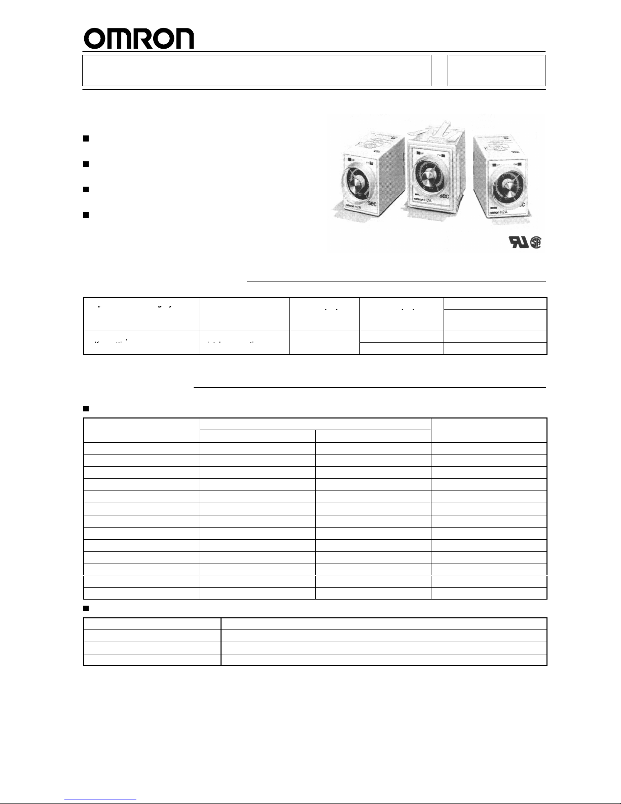
Motor Timer H2A
Miniature, High-performance Motor
Timer
Employs high-reliability bifurcated contacts for
output.
Moving
pointer provided in all types for
confirmation
of elapsed time.
Employs time-out and power ON indicators for all
types.
Wide variety of timing ranges from 5 s to 24 hrs.
Ordering Information
Operation/resetting
system
Internal connection
Time-limit
Instantaneous
Mounting
pgy
contact contact
Surface mounting
(see note 2)
T
ime-limit operation/
Parallel motor and
SPDT --- H2A
p
self-resetting
clutch connection
SPST-NO H2A-H
Note: 1.
Specify both the model number and supply voltage when ordering.
2.
Surface mounting models can be used as a flush mounting type by attaching an exclusive adapter (Y92F-40) to the timer
.
Specifications
Time Ranges
Rated
time
T
ime setting range
T
ime division
50 Hz 60 Hz
5 s
0.2 to 6 s 0.2 to 5 s
0.2 s
10 s
0.5 to 12 s 0.5 to 10 s
0.5 s
30 s
1 to 36 s 1 to 30 s
1.0 s
60 s
2 to 72 s 2 to 60 s
2.0 s
3 min 1/6 to 3 1/2 min 1/6 to 3 min
10.0 s
6 min 1/4 to 7 1/6 min 1/4 to 6 min
15.0 s
12 min 1/2 to 14 min 1/2 to 12 min
30.0 s
30 min 1 to 36 min 1 to 30 min 1.0 min
60 min 2 to 72 min 2 to 60 min 2.0 min
3 hrs
1/6 to 3 1/2 hrs
1/6 to 3 hrs
10.0 min
6 hrs
1/4 to 7 hrs 1/4 to 6 hrs
15.0 min
12 hrs
1/2 to 14 hrs 1/2 to 12 hrs
30.0 min
24 hrs
1 to 28 hrs 1 to 24 hrs
1.0 hrs
Ratings
Rated
supply voltage
100, 1
10, 200, or 220 V
AC (50 Hz), 100/1
10, 200/220 V
AC (60 Hz)
Operating voltage range
85% to 1
10% of rated supply voltage
Power consumption
Approx. 3 V
A
Control outputs
Standard type: 2 A at 250 V
AC, resistive load (cosφ
= 1)
Note:
The front panel of the timer is color-coded to identify the following supply voltage classifications:
100, 1
10 V
: Blue
200, 220 V
: Red
Other classes: Black
Page 2
H2A
H2A
2
Characteristics
Accuracy
of operating time
±
2% max. 〈±3% max. for the 5-s model)
Setting error ±
5% max.
Reset time
0.3 s max.
Influence of voltage
±
1% max.
Influence of temperature
±
2% max.
Insulation resistance
100 MΩ min. (at 500 VDC)
Dielectric strength
2,000 V
AC, 50/60 Hz for 1 min (between current-carrying and non-current-carrying parts,
between contact and control circuit and between) contacts of dif
ferent polarities)
1,000 V
AC, 50/60 Hz for 1 min (between non-continuous contacts)
V
ibration resistance
Destruction:
16.7 Hz with 4-mm double amplitude
Malfunction:
10 to 55 Hz with 0.5-mm double amplitude
Shock resistance
Destruction:
1,000 m/s2 (approx. 100G)
Malfunction:
100 m/s2 (approx. 10G) (5G for lateral shocks)
Ambient temperature
Operating: –10°
C to 50
°C
Ambient humidity
Operating: 45% to 85%
Life expectancy
Mechanical:
1,000,000 operations min. (under no load at operating of 1,800 operations/hr)
Electrical:
See
“Engineering Data”
Motor life expectancy
20,000 hrs
Approved standards
UL (File No. E52800-US), CSA (File No. LR22310-US)
Weight
Approx. 170 g
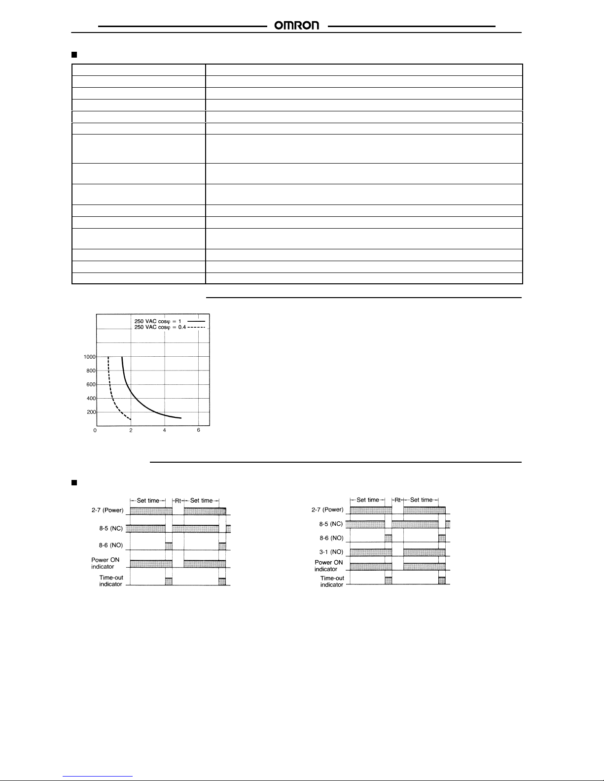
Engineering Data
Switching operations (x 10 )
3
Load current (A)
Operation
Timing Chart
H2A H2A-H
Rt: Resetting time Rt: Resetting time
Page 3

H2A
H2A
3
Dimensions
Note: All
units are in millimeters unless otherwise indicated.
H2A/H2A-H
Note: F-shaped hook (PHC-1)
for PF085A and L-shaped
hook
(PHc-4) for PL08
are
supplied
with the timer
.
H2A(-H) with Adapter
Panel Cutouts
Note: Back
connecting socket US08 and Y
-shaped hook
PHC-3
are supplied with the timers.
Panel
Y92F-40 adapter for
flush mounting
(See note)
Accessories (Order Separately)
Track Mounted/Front Connecting Socket
PF085A Mounting
Holes
T
erminal Arrangement
(T
op V
iew)
Mounting Height of
T
imer with Socket
Adapter for Flush Mounting
Y92F-40
Panel Cutouts
Note: PF085A can be
used as a front
connecting
socket.
Two, 4.5 dia.
holes
Eight, M3.5 ×
7 sems
Two, 4.5 dia. or M4 holes
Top View
Back Connecting Socket
PL08 (Solder Terminals)
Mounting
Holes
T
erminal Arrangement
(Bottom View)
Mounting Height of
T
imer with Socket
Two, 2 dia. holes
Bottom View
Page 4

H2A
H2A
4
Mounting Track (Meets DIN EN50022)
PFP-100N/PFP-50N
(see note)
Note: This
dimension applied to PFP-50N.
End Plate
PFP-M
PFP-S
Hold-down Clips (Attached)
PHC-1 For PF085A
Installation
Terminal Arrangement
H2A H2A-H
Precautions
Mounting
When
two or more timers are to be mounted in line, provide a dis
-
tance of more than 5 mm between the two adjacent timers.
When
two or more timers mounted in line are to be continuously en
-
ergized
at the same time after the set time has elapsed, be sure to
limit
the carry current to less than 1 A.
When using the timers at an ambient temperature of more than
40°C,
be sure to reset the
timers immediately after the set time has
elapsed.
Wiring
When
wiring, employ a multi-core cable
having a finished outer di
ameter of less than 10.5 mm, or insulated (twisted) wires with less
than
a 3 mm outer diameter
.
ALL DIMENSIONS SHOWN ARE IN MILLIMETERS.
To
convert millimeters into inches, multiply by 0.03937. T
o convert grams into ounces, multiply by 0.03527.
Cat. No. L04-E1-8
In the interest of product improvement, specifications are subject to change without notice.
Printed
in Japan
0697-0.5C (0696)
OMRON Corporation
Systems
Components Division
28th Fl., Crystal T
ower Bldg.
1-2-27, Shiromi, Chuo-ku,
Osaka 540 Japan
Phone: 06-949-6012 Fax: 06-949-6021
 Loading...