

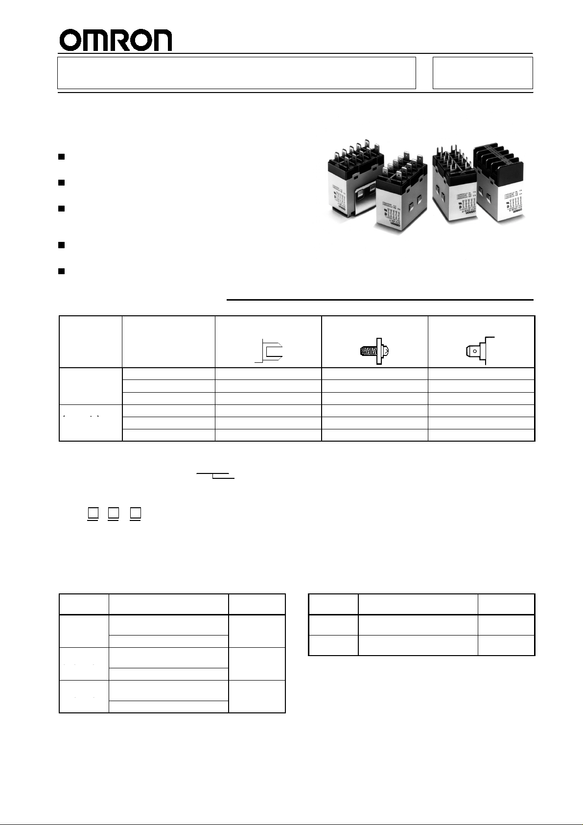
Power Relay G7J
SSC
S
C
A High-capacity,
High-dielectric-strength, Multi-pole
Relay Used Like a Contactor
Miniature hinge for maximum switching power for
motorloadsaswellasresistiveandinductiveloads.
No contact chattering for momentary voltage drops
up to 50% of rated voltage.
Withstandingmorethan4kVbetweencontactsthat
are different in polarity and between the coil and
contacts.
Flame-resistant materials (UL94V-0-qualifying)
used for all insulation material.
Standard models approved by UL and CSA.
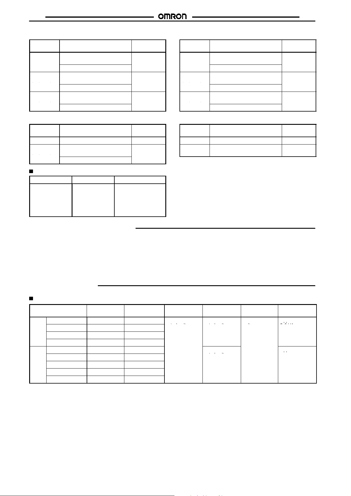
Ordering Information
RC
Mounting type Contact form PCB terminals Screw terminals Quick-connect
PCB mounting
W-bracket
(see note)
These Relays need a W-bracket (sold separately) for mounting.
Note:
When ordering specify the voltage.
4PST-NO G7J-4A-P, G7J-4A-PZ --- --3PST-NO/SPST-NC G7J-3A1B-P, G7J-3A1B-PZ --- --DPST-NO/DPST-NC G7J-2A2B-P --- --4PST-NO --- G7J-4A-B, G7J-4A-BZ G7J-4A-T , G7J-4A-TZ
3PST-NO/SPST-NC --- G7J-3A1B-B, G7J-3A1B-BZ G7J-3A1B-T, G7J-3A1B-TZ
DPST-NO/DPST-NC --- G7J-2A2B-B G7J-2A2B-T
Example: G7J-4A-P 240 VAC
Rated coil voltage
terminals
Model Number Legend
G7J - - -
12
PCB Terminals
Contact
form
4PST-NO
3PST-NO/
SPST-NC
DPST-NO/
DPST-NC
24, 50, 100 to 120,
200 to 240 VAC
12, 24, 48, 100 VDC
24, 50, 100 to 120,
200 to 240 VAC
12, 24, 48, 100 VDC
24, 50, 100 to 120,
200 to 240 VAC
12, 24, VDC
3
1. Contact Form
4A: 4PST-NO
3A1B: 3PST-NO/SPST-NC
2A2B: DPST-NO/DPST-NC
Rated voltage (V) Model
G7J-4A-P
G7J-3A1B-P
G7J-2A2B-P
2. Terminal Shape
P: PCB terminals
B: Screw terminals
T: Quick-connect terminals
(#250 terminal)
3. Contact Structure
Z: Bifurcated contact
None: Single contact
Note:
PCB Terminals (Bifurcated Contact)
Contact
form
4PST-NO 200 to 240 VAC
3PST-NO/
SPST-NC
Rated voltage (V) Model
24 VDC
12, 24 VDC G7J-3A1B-PZ
For bifurcated contact type,
output is 1NO (4PST-NO) or
1NC (3PST-NO/SPST-NC).
G7J-4A-PZ
1
G7J
SSC
S
C
SSC
SSC
S
C
p
p
p
p
G7J
W-bracket Screw Terminals
Contact
form
4PST-NO
3PST-NO/
SPST-NC
DPST-NO/
DPST-NC
Rated voltage (V) Model
24, 50, 100 to 120,
200 to 240 VAC
12, 24 VDC
24, 50, 100 to 120,
200 to 240 VAC
12, 24 VDC
24, 50, 100 to 120,
200 to 240 VAC
12, 24, VDC
G7J-4A-B
G7J-3A1B-B
G7J-2A2B-B
Screw Terminals (Bifurcated Contact)
Contact
form
4PST-NO Under registration G7J-4A-BZ
3PST-NO/
SPST-NC
Rated voltage (V) Model
24, 50, 100 to 120,
200 to 240 VAC
6, 12, 24, 48, 100, 110 VDC
G7J-3A1B-BZ
Accessories (Order Separately)
Name Model Applicable Relay
W-bracket
R99-04 for G5F G7J-4A-B
G7J-3A1B-B
G7J-2A2B-B
G7J-4A-T
G7J-3A1B-T
G7J-2A2B-T
Tab Terminals
Contact
form
4PST-NO
3PST-NO/
SPST-NC
DPST-NO/
DPST-NC
Rated voltage (V) Model
24, 50, 100 to 120,
200 to 240 VAC
12, 24 VDC
24, 50, 100 to 120,
200 to 240 VAC
12, 24 VDC
24, 50, 100 to 120,
200 to 240 VAC
12, 24, VDC
G7J-4A-T
G7J-3A1B-T
G7J-2A2B-T
T a b Terminals (Bifurcated Contact)
Contact
form
4PST-NO 100 to 120, 200 to 240 VAC G7J-4A-TZ
3PST-NO/
SPST-NC
Rated voltage (V) Model
Under registration G7J-3A1B-TZ
Application Examples
Compressors for air conditioners and heater switching
!
controllers.
Switching controllers for power tools or motors.
!
Lamp controls, motor drivers, and power supply switching
!
controllers in copy machines, facsimile machines, and other
office equipment.
Power controllers for packers or food processing equipment.
!
Power controllers for inverters.
!
Specifications
Coil Ratings
Rated voltage Rated current Coil resistance Must-operate
AC
24 VAC
50 VAC
100 to 120 VAC
200 to 240 VAC
DC
6VDC
12 VDC
24 VDC
48 VDC
100 VDC
1. Theratedcurrentandcoilresistancearemeasuredatacoiltemperatureof23#Cwithtolerancesof +15%/--20%forACratedcurrent
Note:
and$15% for DC coil resistance. (The values given for AC rated current apply at 50 Hz or 60 Hz.)
2. Performance characteristic data are measured at a coil temperature of 23#C.
3. The maximum voltage is one that is applicable to the Relay coil at 23#C.
75 mA --36 mA --18 to 21.6 mA --9to10.8mA --333 mA 18
167 mA 72
83 mA 288
42 mA 1,150
20 mA 5,000
"
"
"
"
"
voltage
75% max. of
rated voltage rated voltage voltage
Must-release
voltage
15% min. of
10% min. of
rated voltage
Max. voltage Power
110% of rated
consumption
Approx. 1.8 to
2.6 VA
Approx. 2.0 W
2
G7J
Contact Ratings
Item Resistive load (cos%=1) Inductive load (cos%=0.4) Resistive load
Contact mechanism
Contact material
Rated load
Rated carry current
Max. switching voltage
Max. switching current
The values in parentheses indicate values for a bifurcated contact.
Note:
Double break
Ag alloy
NO: 25 A at 220 VAC (24 A at 230 VAC)
NC: 8 A at 220 VAC (7.5 A at 230 VAC)
NO: 25 A (1 A)
NC: 8 A (1 A)
250 VAC 125 VDC
NO: 25 A (1 A)
NC: 8 A (1 A)
NO: 25 A at 30 VDC
NC: 8 A at 30 VDC
Characteristics
Contact resistance (see note 2)
Operate time (see note 3)
Release time (see note 3)
Max. operating frequency
Insulation resistance (see note 4)
Dielectric strength
Impulse withstand voltage
Vibration resistance
Shock resistance
Life expectancy
Error rate (see note 6)
Ambient temperature
Ambient humidity
Weight
1. The above values are all initial values.
Note:
2. The contact resistance was measured with 1 A at 5 VDC using the voltage drop method.
3. Theoperateandthe release times weremeasuredwiththerated voltage imposed with any contact bounce ignoredatanambient
temperature of 23#C.
4. Theinsulationresistancewas measuredwitha500-VDCmeggerappliedtothesame placesasthoseusedfor checkingthedielectric strength.
5. The electrical life expectancy was measured at an ambient temperature of 23#C.
6. This value was measured at a switching frequency of 60 operations per minute.
50 m"max.
50 ms max.
50 ms max.
Mechanical: 1,800 operations/hr
Electrical: 1,800 operations/hr
1,000 M"min. (at 500 VDC)
4,000 VAC, 50/60 Hz for 1 min between coil and contacts
4,000 VAC, 50/60 Hz for 1 min between contacts of different polarity
2,000 VAC, 50/60 Hz for 1 min between contacts of same polarity
10,000 V between coil and contact (with 1.2 x 50&s impulse wave)
Destruction: 10 to 55 Hz, 1.5-mm double amplitude
Malfunction: NO: 10 to 55 Hz, 1.5-mm double amplitude
Destruction:1,000 m/s
Malfunction:NO: 100 m/s
Mechanical: 1,000,000 operations min. (at 1,800 operations/hr)
Electrical: 100,000 operations min. (at 1,800 operations/hr) (see note 5)
100 mA at 24 VDC (bifurcated contact: 24 VDC 10 mA)
Operating: --25#Cto60#C (with no icing or condensation)
Storage: --25#Cto60#C (with no icing or condensation)
Operating: 35% to 85%
Storage: 35% to 85%
PCB terminal: approx. 140 g
Screw terminal: approx. 165 g
Quick-connect terminal: approx. 140 g
NC: 10 to 26 Hz, 1.5-mm double amplitude
2
2
NC: 20 m/s
2
G7J
3

G7J
,
,
,
,
g
g
G7J
Approved by Standards
TheG7Jsatisfies thefollowinginternationalstandards.Approvalfor someinternationalmarkingsand symbolsarestillpending,however,and
information on them will be added when they are approved.
UL (File No. E41643)
CSA (File No. LR35535)
Coil ratings Contact ratings Number of test
24 to 265 VAC
6to110VDC
NO contact
NC contact
25 A 277 VAC, Resistive
25 A 120 VAC, General Use
25 A 277 VAC, General Use
1.5 kW 120 VAC, Tungsten
1.5 hp 120 VAC
3 hp 240/265/277 VAC
3-phase 3 hp 240/265/277 VAC
3-phase 5 hp 240/265/277 VAC
20FLA/120LRA 120 VAC
17FLA/102LRA 277 VAC
TV-10 120 VAC 25,000
25 A 30 VDC, Resistive 30,000
1 A 277 VAC, General Use 6,000
8 A 277 VAC,Resistive
8 A 120 VAC, General Use
8 A 277 VAC, General Use
8 A 30 VDC, Resistive
1 A 277 VAC, General Use 6,000
operations
30,000
6,000
30,000
30,000
Reference
UL approval: UL508 for industrial control devices
CSA approval: CSA C22.2 No. 14 for industrial control devices
UL1950 for information processing equipment including business machines
CSA C22.2 No. 950 for information processing equipment including business machines
VDE (File No. 5381UG)
Model Coil ratings
G7J-4A-B(P) (T) (Z)
G7J-2A2B(P) (T)
G7J-3A1B-B(P) (T) (Z)
Add the suffix “-KM” to the model number when ordering.
Note:
* These ratings are bifurcated contact ratings.
Reference
VDE approval: VDE0435 for electromagnetic relays
IEC255 for relays
6, 12, 24, 48, 100 VDC
24, 50, 100 to 120, 200 to 240 VAC
KEMA (File No. 97.9140.01)
Model Coil ratings
G7J-4A-B(P) (T) (Z)
G7J-2A2B(P) (T)
G7J-3A1B-B(P) (T) (Z)
Add the suffix “-KM” to the model number when ordering.
Note:
* This rating is the bifurcated contact rating.
Reference
KEMA approval: EN60947-4-1 for contacts
IEC947-4-1 for contacts
6, 12, 24, 48, 100 VDC
24, 50, 100 to 120, 200 to 240 VAC
NO contact NC contact
25 A 240 VAC cos%=0.4
25 A 240 VAC cos%=1
25 A 30 VDC L/R≧1
*1 A 240 VAC cos%=0.4
Contact ratings
8 A 240 VAC cos%=0.4
8 A 240 VAC cos%=1
8A30VDCL/R≧1
*1 A 240 VAC cos%=0.4
Contact ratings
NO contact
Class AC1: 25 A at 220 VAC
11.5 A at 380 to 480 VAC
Class AC3: 11.5 A at 220 VAC and 8.5 A at
380 to 480 VAC
*Class AC 1 : 1 A at 220 VAC
4

G7J
Engineering Data
Maximum Switching Power Life Expectancy
G7J
AC resistiveload
(cos'=1)
AC inductive load
(cos'=0.4)
(NO contact)
DC resistive
load (NO
contact)
Switching current (A)
DC resistiveload
(NC contact)
Switching voltage (V) Switching current (A)
Malfunctioning Shock
G7J-2A2B
A1 downwards
Button upwards
Unit: m/s
2
Terminals upwards
Not energized
Terminals
downwards
Energized
AC resistiveload
(cos'=1)
AC inductive load
(cos'=0.4)
(NC contact)
Button downwards
A2 downwards
Shock direction
5,000
3,000
1,000
3
700
500
300
100
Life expectancy (x10 operations)
70
50
Number of samples: 5
Measurement conditions: Increaseand decrease
the specified shockgradually imposed in$X,$Y,
and$Z directions three times each with theRelay
energized and not energized to check the shock
values that causethe Relay to malfunction.
Criteria: There mustnot be any contact
separation for 1 ms or greater with a shock of
100 m/s2imposed when thecoil is energized or
with a shock of20 m/s2when the coilis not
energized.
220 VAC (NO contact)
220 VAC (NC contact)
5

G7J
G7J
Ambient Temperature vs. Must-operate
and Must-release Voltage
G7J 100 to 120 VAC
Number of Relays: 5
Must-operate and reset voltage (%)
Ambient temperature (#C)
Must-operate voltage
Must-release voltage
Ambient Temperature vs.
Coil Temperature Rise
G7J-4A 100 to 120 VAC
Number of Relays: 5
#
Coil temperature rise ( C)
G7J24VDC G7J-4A24VDC
Number of Relays: 5
Must-operate voltage
Must-release voltage
Number of Relays: 5
#
Ambient temperature (#C)
Must-operate and reset voltage(%)
Motor Load
Load
Life expectancy
Coil temperature rise ( C)
Ambient temperature (#C)
Ambient temperature (#C)
Item G7J-4A-P, G7J-3A1B-P, G7J-4A-B, G7J-3A1B-B, G7J-4A-T, G7J-3A1B-T
3%, 220 VAC, 2.7 kW (with a inrush current of 78 A and a breaking current of 13 A)
Electrical: 100,000 operations min.
6

G7J
Dimensions
All units are in millimeters unless otherwise indicated.
Note:
Screw Terminals with W-bracket
G7J-4A-B, G7J-4A-BZ, G7J-3A1B-B, G7J-3A1B-BZ, G7J-2A2B-B
Ten, M3.5
34.5 max.
7.6
G7J
Mounting Holes
Two, 4.5 dia. or M4
4.3
55.2
51.5 max.
43.2
2
Quick-connect Terminals with W-bracket
G7J-4A-T, G7J-4A-TZ, G7J-3A1B-T, G7J-3A1B-TZ, G7J-2A2B-T
34.5 max.
Note: W-bracket is sold
separately.
51.5 max.
35+0.1
64 max.
Mounting Holes
Two, 4.5 dia. or M4
64 max.
PCB Terminals with PCB Mounting
G7J-4A-P, G7J-4A-PZ, G7J-3A1B-P, G7J-3A1B-PZ, G7J-2A2B-P
33.5
max.
51.5 max.
Mounting Dimensions
Two, 4.5 dia. or M4
51 max.
7

G7J
Terminal Arrangement/Internal Connections
G7J-4A-P(B) (T) (Z)
G7J-3A1B-P(B) (T) (Z) G7J-2A2B-P(B) (T)
G7J
14
24
34
44
A2
13
23
33
43
A1
14
24
34
42
A2
The coil hasno polarity.
Accessories (Order Separately)
R99-04 W-bracket (for G5F)
35
30
44
13
23
33
41
A1
Two, M4 or 4.5 dia.
24
9
29
4.4
14
24
32
42
A2
13
23
31
41
A1
Terminals 43 and 44 of the
Note:
G7J-4A-P(B)(T)(Z) andcontacts41
and42oftheG7J-3A1B-P(B)(T)(Z)
are bifurcated contacts.
Mounting Holes
Two, M4
28
7
35$0.1
Precautions
Refer to page NO TAG for general precautions.
Installation
PCB Terminal-equipped Relays weigh approximately 140 g. Be
sure that the PCB is strong enough to support them. We recommend dual-side through-hole PCBs to reduce solder cracking from
heat stress.
Mount the G7J with its test button facing downwards. The Relay
may malfunction due to shock if the test button faces upwards. Be
carefulnotto pressthetest buttonbymistakebecausethe contacts
will go ON if the test button is pressed.
Be sure to use the test button for test purposes only.
ThetestbuttonisusedforRelaycircuittests,suchasacircuitcontinuity test. Do not attempt to switch the load with the test button.
Minute Loads
The G7J is used for switching power loads, such as motor, transformer, solenoid, lamp, and heater loads. Do not use the G7J for
switching minute loads, such as signals. Use a Relay with a bifurcated contact construction for switching minute loads, in which
case, however, only SPST-NO or SPST-NC output is obtained.
Soldering PCB Terminals
Be sure to solder the PCB terminals manually only. In the case of
automatic soldering, some flux may stick to the test button andthe
G7J. As a result, the G7J may malfunction.
TheG7J isnotofenclosedconstruction.Therefore, donot washthe
G7J with water or any detergent.
Connecting
Refertothefollowingdiagramwhen connecting a wirewitha screw
terminal to the G7J.
7.6
7
4.5
M3.5
Allow suitable slack on leads when wiring, and do not subject the
terminals to excessive force.
Tightening torque: 0.98 NSm
Donot imposeexcessiveexternalforceonthe G7Jinthehorizontal
or vertical directions when inserting the G7J to the Faston receptacle or pulling the G7J out from the Faston receptacle. Do not attempt to insert or pull out more than one G7J Unit together.
Do not solder the tab terminals.
Terminal
#250
terminal
(6.35 mm
in width)
Receptacle Housing
AMP170333-1
(170327-1)
AMP170334-1
(170328-1)
AMP170335-1
(170329-1)
Numbers in parentheses are for air feed use.
Note:
8.8
AMP172076-1: natural
AMP172076-4: yellow
AMP172076-5: green
AMP172076-6: blue
8

G7J
Operating Coil
Internal Connections of Coils
DC coil
A2 A1
AC coil
A2 A1
If a transistor drives the G7J, check the leakage current, and connect a bleeder resistor if necessary.
The AC coil is provided with a built-in full-wave rectifier. If a triac,
such as anSSR,drivestheG7J,theG7Jmay notrelease. Besure
toperformatrialoperationwiththeG7Jandthetriac beforeapplying
them to actual use.
G7J
ALL DIMENSIONS SHOWN ARE IN MILLIMETERS.
To convert millimeters into inches, multiply by 0.03937. To convert grams into ounces, multiply by 0.03527.
Cat. No. J088-E1-2A
9
 Loading...