

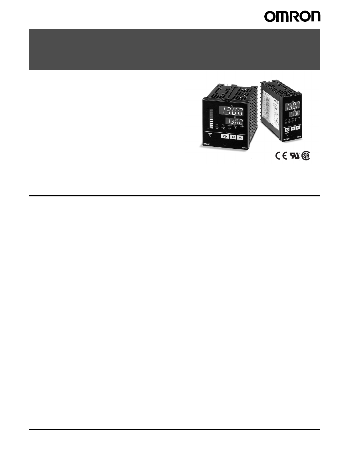
Digital Controller
E5AK/E5EK
Advanced Digital Controllers Ideal for
Worldwide Use
• Modular structure
• High-accuracy: 100 ms sampling (for analog input)
• Auto-tuning and fuzzy self-tuning
• Conforms to international EMC and safety standards.
• IP66/NEMA4 (indoor use) front face
• Remote set point
• Serial communications (RS-232C, RS-422 and RS-485) and
transfer output (4 to 20 mA)
• Position-proportional control model
• Heating/cooling control
• AC/DC24V types are also available.
Model Number Structure
■ Model Number Legend
®
E5@K- @@@ @ -500
123
1. Size
A: 96
E: 96
2. Model
AA: Standard model
PRR: Position-proportional model
3. Number of alarms
2: Two alarms
× 96 mm
× 48 mm
Digital Controller E5AK/E5EK 1
Ordering Information
■ List of Models
Description Model Specification
Base Unit E5AK-AA2 AC100-240 Standard model
E5AK-AA2-500 AC100-240 Standard model with terminal cover
E5AK-AA2 AC/DC24 Standard model
E5AK-AA2-500 AC/DC24 Standard model with terminal cover
E5AK-PRR2 AC100-240 Position-proportional model
E5AK-PRR2-500 AC100-240 Position-proportional model with terminal cover
E5AK-PRR2 AC/DC24 Position-proportional model
E5AK-PRR2-500 AC/DC24 Position-proportional model with terminal cover
E5EK-AA2 AC100-240 Standard model
E5EK-AA2-500 AC100-240 Standard model with terminal cover
E5EK-AA2 AC/DC24 Standard model
E5EK-AA2-500 AC/DC24 Standard model with terminal cover
E5EK-PRR2 AC100-240 Position-proportional model
E5EK-PRR2-500 AC100-240 Position-proportional model with terminal cover
E5EK-PRR2 AC/DC24 Position-proportional model
E5EK-PRR2-500 AC/DC24 Position-proportional model with terminal cover
Note: 1. When using the heater burnout alarm function with a standard model, the Linear Output Unit cannot be used for the control outputs (heat).
2. Be sure to specify the Current Transformer, Output Unit, and Option Unit when ordering.
3. The Digital Controller provides transfer outputs at 4 to 20 mA for the PV and other values and control outputs at 4 to 20 mA for the current
outputs.
Description Model Specification
Output Unit E53-R Relay
E53-S SSR
E53-Q Pulse (NPN) 12 VDC
E53-Q3 Pulse (NPN) 24 VDC
E53-Q4 Pulse (PNP) 24 VDC
E53-C3 Linear (4 to 20 mA)
E53-C3D Linear (0 to 20 mA)
E53-V34 Linear (0 to 10 V)
E53-V35 Linear (0 to 5 V)
Note: The Digital Controller uses a dedicated, high-resolution Output Unit. The E53-C Current Output Unit for the E5@X cannot be used with the
Digital Controller.
Description Model Specification
Option Unit E53-AKB Event input
E53-EN01 Communication (RS-232C)
E53-EN02 Communication (RS-422)
E53-EN03 Communication (RS-485)
E53-AKF Transfer output
Note: 1. The Option Unit can be used either by the E5AK or E5EK.
2. The E5AK allows a maximum of three Option Units to be mounted. Refer to page 8 for mounting combinations.
The E5EK allows only one Option Unit to be mounted.
Inspection Report
The Digital Controller can be provided together with an inspection report.
Refer to the following legend with the suffix “K” when ordering a model provided together with an inspection report.
E5@K-AA2-K, E5@K-PRR2-K, E53-AKF-K
2 Digital Controller E5AK/E5EK
■ Accessories (Order Separately)
Name Model Hole diameter
Current Transformer E54-CT1 5.8 mm
E54-CT3 12.0 mm
Note: No CT is required unless the heater burnout alarm function is used.
Name Model Connectable models
Terminal Cover E53-COV0809 E5AK
E53-COV08 E5EK
Specifications
■ Ratings
Item AC100-240V type AC/DC24V type
Supply voltage AC100 to 240V, 50/60 Hz AC/DC24V, 50/60 Hz
Power consumption E5AK: 16 VA
Operating voltage range 85% to 110% of rated supply voltage
Input Thermocouple: K, J, T, E, L, U, N, R, S, B, W, PLII
Input impedance Current input: 150
Control output Standard Model
Auxiliary output SPST-NO, 3 A at 250 VAC (resistive load)
Control method (see note 2) ON/OFF or 2-PID control (with auto-tuning)
Setting method Digital setting using front panel keys
Indication method 7-segment digital display and LEDs
Potentiometer 100
Event input Contact input: ON: 1 kΩ max., OFF: 100 kΩ min.
Transfer output 4 to 20 mA, permissible load impedance: 600
Remote SP input Current input: 4 to 20 mA (Input impedance: 150
Current Transformer input Connect an exclusive Current Transformer (E54-CT1 or E54-CT3)
Other functions Standard
Degree of protection Conforms to IEC IP66 and NEMA4 (Indoor use)
Note: 1. All control outputs are insulated from the input circuit.
2. Fuzzy self-tuning is available when using the Digital Controller in standard control operation with temperature input.
E5EK: 15 VA
Platinum resistance thermometer: JPt100, Pt100
Current input: 4 to 20 mA, 0 to 20 mA
Voltage input: 1 to 5 V, 0 to 5 V, 0 to 10 V
Ω; Voltage input: 1 MΩ min.
According to Output Unit (see “Output Unit Ratings and Characteristics”)
Position-proportional Model
2 Relay outputs: SPST-NO, 1 A at 250 VAC (including inrush current) (see note 1)
Ω to 2.5 kΩ
No-contact input: ON: residual voltage: 1.5 V max., OFF: leakage current: 0.1 mA max.
Manual output, heating/cooling control, SP limiter, loop burnout alarm, SP ramp, MV limiter, MV
change rate limiter, input digital filter, input shift, run/stop, protect functions
Option
Multiple SP, run/stop selection, transfer output functions
12 VA, 8 W
Ω max., resolution: approx. 2,600
Ω)
■ Input Ranges
Platinum Resistance Thermometer
Input (switch selectable) JPt100 Pt100
Range
Setting 01
°C −199.9 to 650.0 −199.9 to 650.0
°F −199.9 to 999.9 −199.9 to 999.9
Digital Controller E5AK/E5EK 3
Thermocouple
Input (switch
selectable)
(see note)
Range
Setting 23456 78910111213141516
Note: Setting number is factory-set to 2 (K1).
Thermocouple W is W/Re5-26 (tungsten rhenium 5, tungsten rhenium 26).
K1 K2 J1 J2 T E L1 L2 U N R S B W PLII
°C −200
to
1,300
°F −300
to
2,300
0.0 to
500.0
0.0 to
900.0
−100
to 850
−100
to
1,500
0.0 to
400.0
0.0 to
750.0
−199.9
to 400.0
−199.9
to 700.0
0 to
600
0 to
1,100
−100
to 850
−100
to
1,500
0.0 to
400.0
0.0 to
750.0
−199.9
to 400.0
−199.9
to 700.0
−200
to
1,300
−300
to
2,300
0 to
1,700
0 to
3,000
0 to
1,700
0 to
3,000
100 to
1,800
300 to
3,200
0 to
2,300
0 to
4,100
0 to
1,300
0 to
2,300
Current/Voltage
Input (switch selectable) Current input Voltage input
4 to 20 mA 0 to 20 mA 1 to 5 V 0 to 5 V 0 to 10 V
Range One of following ranges depending on results of scaling
Setting 17 18 19 20 21
−1999 to 9999
−199.9 to 999.9
−19.99 to 99.99
−1.999 to 9.999
4 Digital Controller E5AK/E5EK
■ Characteristics
Indication accuracy (see note 1) Thermocouple:
±0.3% of indication value or ±1°C, whichever greater) ±1 digit max.
(
Platinum resistance thermometer:
(
±0.2% of indication value or ±0.8°C, whichever greater) ±1 digit max.
Analog input:
±0.2% FS ±1 digit max.
Hysteresis 0.01% to 99.99% FS (in units of 0.01% FS)
Proportional band (P) 0.1% to 999.9% FS (in units of 0.1% FS)
Integral (reset) time (I) 0 to 3,999 s (in units of 1 s)
Derivative (rate) time (D) 0 to 3,999 s (in units of 1 s)
Control period 1 to 99 s (in units of 1 s)
Manual reset value 0.0% to 100.0% (in units of 0.1%)
Alarm setting range
−1,999 to 9,999 or −199.9 or 999.9 (decimal point position dependent on input type or result of scaling)
Sampling period (see note 2) Temperature input: 250 ms
Current/voltage input: 100 ms
Insulation resistance 20 M
Ω min. (at 500 VDC)
Dielectric strength 2,000 VAC, 50/60 Hz for 1 min between terminals of different polarities
Vibration resistance
Malfunction: 10 to 55 Hz, 10 m/s
Destruction: 10 to 55 Hz, 20 m/s
Shock resistance
Malfunction: 200 m/s
Destruction: 300 m/s
Ambient temperature Operating:
Storage:
2
min. (approx. 20G), 3 times each in 6 directions
(100 m/s
2
(approx. 10G) applied to the relay)
2
min. (approx. 30G), 3 times each in 6 directions
−10°C to 55°C (with no icing)/3-year warranty period: –10°C to 50°C
−25°C to 65°C (with no icing)
2
(approx. 1G) for 10 min each in X, Y, and Z directions
2
(approx. 2G) for 2 hrs each in X, Y, and Z directions
Ambient humidity Operating: 35% to 85%
Degree of protection Front panel: NEMA4 for indoor use (equivalent to IP66)
Rear case: IEC standard IP20
Terminals: IEC standard IP00
Memory protection Non-volatile memory (number of writings: 100,000 operations)
Weight E5AK: approx. 450 g
E5EK: approx. 320 g
Mounting bracket: approx. 65 g
EMC Emission Enclosure: EN55011 Group 1 class A
Emission AC Mains: EN55011 Group 1 class A
Immunity ESD: EN61000-4-2: 4 kV contact discharge (level 2)
8 kV air discharge (level 3)
Immunity RF-interference: ENV50140: 10 V/m (amplitude modulated, 80 MHz to 1 GHz)
(level 3)
10 V/m (pulse modulated, 900 MHz)
Immunity Conducted Disturbance: ENV50141: 10 V (0.15 to 80 MHz) (level 3)
Immunity Burst: EN61000-4-4: 2 kV power-line (level 3)
2 kV I/O signal-line (level 4)
Approved standards UL1092, CSA22.2 No. 142, CSA22.2 No. 1010-1
Conforms to EN50081-2, EN50082-2, EN61010-1 (IEC1010-1)
Conforms to VDE0106/part 100 (Finger Protection), when the separately-ordered terminal cover is
mounted.
Note: 1. The indication accuracy of the K1, T, and N thermocouples at a temperature of −100°C or less is ±2°C ±1 digit maximum. The indication
accuracy of the U, L1, and L2 thermocouples at any temperature is
The indication accuracy of the B thermocouple at a temperature of 400
The indication accuracy of the R and S thermocouples at a temperature of 200
The indication accuracy of the W thermocouple at any temperature is (
±2°C ±1 digit maximum.
°C or less is unrestricted.
°C or less is ±3°C ±1 digit maximum.
±0.3% of the indicated value or ±3°C, whichever is greater) ±1 digit
maximum.
The indication accuracy of the PLII thermocouple at any temperature is (
±0.3% or ±2°C, whichever is greater) ±1 digit maximum.
2. The sampling period of the standard model with CT and remote SP inputs is 250 ms.
Digital Controller E5AK/E5EK 5
■ Output Unit Ratings and Characteristics
Relay output 5 A at 250 VAC (resistive load)
SSR output 1 A at 75 to 250 VAC (resistive load)
Voltage output NPN: 40 mA at 12 VDC (with short-circuit protection)
Linear current output 4 to 20 mA, permissible load impedance: 600
Linear voltage output 0 to 10 VDC, permissible load impedance: 1 k
Note: An output relay (1 A at 250 VAC) is mounted on the position-proportional model. (When replacing, use the E53-R.)
NPN: 20 mA at 24 VDC (with short-circuit protection)
PNP: 20 mA at 24 VDC (with short-circuit protection)
0 to 20 mA, permissible load impedance: 600
0 to 5 VDC, permissible load impedance: 1 k
Ω max., resolution: approx. 2,600
Ω max., resolution: approx. 2,600
Ω max., resolution: approx. 2,600
Ω max., resolution: approx. 2,600
■ Option Unit Ratings and Characteristics
Event inputs Contact input:
Communications Interface: RS-232C, RS-422 or RS-485
Transfer output 4 to 20 mA:
ON: 1 k
Ω max., OFF: 100 kΩ min.
No-contact input:
ON: residual voltage 1.5 V max., OFF: leakage current 0.1 mA max.
Transmission method: Half-duplex
Synchronization method: Start-stop synchronization (asynchronous method)
Baud rate: 1.2/2.4/4.8/9.6/19.2 kbps
Transmission code: ASCII
Permissible load impedance: 600
Resolution: approx. 2,600
Ω max.
■ Current Transformer Ratings
Dielectric strength 1,000 VAC (for 1 min)
Vibration resistance
Weight E54-CT1: approx. 11.5 g; E54-CT3: approx. 50 g
Accessories (E54-CT3 only) Armature: 2; Plug: 2
50 Hz, 98 m/s
2
(10G)
■ Heater Burnout Alarm
Max. heater current Single-phase 50 A VAC (see note 1)
Heater current value display accuracy
Heater burnout alarm setting range 0.1 to 49.9 A (in units of 0.1 A) (see note 2)
Min. detection ON time 190 ms (see note 3)
Note: 1. Use the K2CU-F@@A-@GS (with gate input terminals) for the detection of three-phase heater burnout.
2. The heater burnout alarm is always OFF if the alarm is set to 0.0 A and always ON if the alarm is set to 50.0 A.
3. No heater burnout detection or heater current value measurement is possible if the control output (heat) is ON for less than 190 ms.
±5% FS±1 digit max.
6 Digital Controller E5AK/E5EK
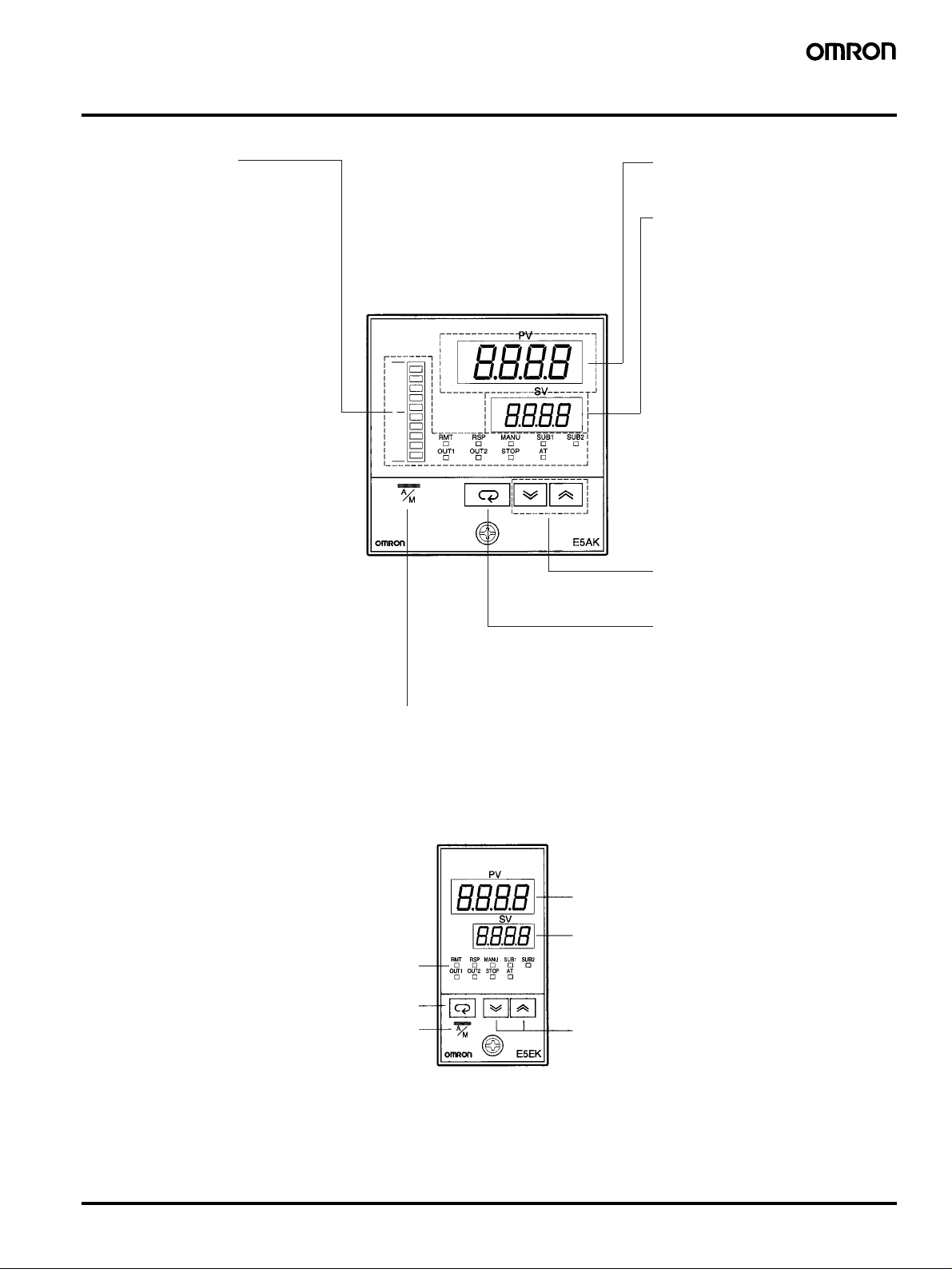
Nomenclature
E5AK
Operation Indicators
OUT1
•
Lights when the pulse output
function assigned to control output
1 turns ON.
•
OUT2
Lights when the pulse output
function assigned to control output
2 turns ON.
• SUB1
Lights when the output function
assigned to auxiliary output 1
turns ON.
• SUB2
Lights when the output function
assigned to auxiliary output 2
turns ON.
• MANU
Lights when the manual operation
mode.
• STOP
Lights during operation has
stopped.
• RMT
Lights during remote operation.
• AT
Flashes during auto-tuning.
• RSP
Lights during remote SP operation.
• Bar Graph
On a standard model (E5AKAA2), this bar graph indicates the
manipulated variable (heat) in
10% increments per single segment. On a position-proportional
model (E5AK-PRR2), this bar
graph indicates the valve opening
in 10% increments per single segment.
No. 1 Display
Displays the process value or parameter symbols.
No. 2 Display
Displays the set point, manipulated
variable, or parameter settings.
Up Key/Down Key
Press to increase or decrease the
value on the No.2 display.
Display Key
Press for less than 1 s to shift the
display to the next parameter. When
this key is pressed for 1 s or more,
the menu screen will be displayed in
any case.
A/M Key
Press to select the auto operation or
manual operation.
E5EK
Operation indicators
Display Key
A/M Key
No. 1 display
No. 2 display
Up Key/Down Key
Digital Controller E5AK/E5EK 7
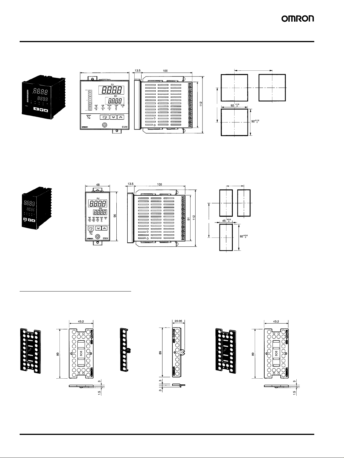
Dimensions
Note: All units are in millimeters unless otherwise indicated.
E5AK
E5EK
96 × 96
Panel Cutouts
91 × 91
120 min.
Note: 1. Recommended panel thickness is 1 to 8 mm.
2. Maintain the specified vertical and horizontal
mounting space between each Unit. Units must
not be closely mounted vertically or horizontally.
Panel Cutouts
60 min.
120 min.
110 min.
Note: 1. Recommended panel thickness is 1 to 8 mm.
2. Maintain the specified vertical and horizontal
mounting space between each Unit. Units must
not be closely mounted vertically or horizontally.
Accessories (Order Separately)
Terminal Cover
E53-COV0809 E53-COV08
8 Digital Controller E5AK/E5EK
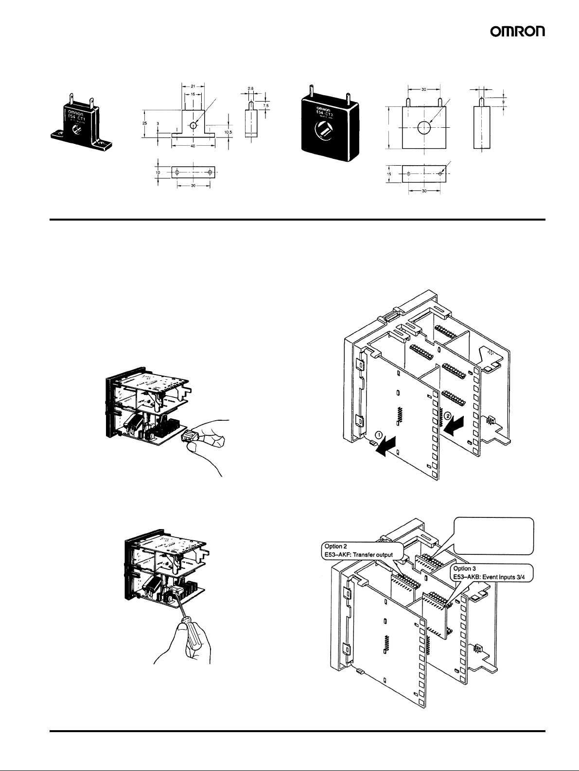
Current Transformer
E54-CT1 E54-CT3
5.8 dia.
40x40
Installation
Note: Always turn off the power supply to the Digital Controller before changing any switch settings.
■ Settings
On a standard model, set up the Output Units for control outputs 1
and 2 before mounting the Controller.
On a position-proportional model, the Relay Output Unit is already
set. Therefore, this setup operation is unnecessary. (Do not replace
with other Output Units.)
When setting up the Output Units, draw out the internal mechanism
from the housing and insert the Output Units into the sockets for control outputs 1 and 2.
Setting Up the Option Unit
•E5AK
1. Remove the power board and option boards in the order shown in
the following diagram.
2.36 dia.
12 dia.
Two, M3 (depth: 4)
Setting Up the Output Unit
Removing the Output Unit
To replace the Output Unit, use a flat-blade screwdriver to push up
the Output Unit.
2. Insert the Option Units into the sockets for options 1 to 3. The following diagram shows the relationship between the Option Units
and mounting positions.
Option 1
E53-AKB: Event inputs 1/2
E53-EN01: RS-232C
E53-EN02: RS-422
E53-EN03: RS-485
3. Mount the option boards and the power board in the order shown.
Digital Controller E5AK/E5EK 9
•E5EK
1. Remove the power board and option boards in the order shown in
the following diagram.
2. Insert the Option Unit into the socket for option 1. The following
diagram shows the relationship between the Option Unit and
mounting position.
Option 1
E53-AKB: Event inputs 1/2
E53-EN01: RS-232C
E53-EN02: RS-422
E53-EN03: RS-485
E53-AKF: Transfer output
Draw-out
To draw out the internal mechanism from the housing, use a Phillips
screwdriver matching the screw on the lower part of the front panel.
1. Turn the screw counterclockwise while pressing the hook on the
upper part of the front panel.
Hook
2. Draw out the internal mechanism while holding the left and right
sides of the front panel.
Mounting
1. Insert the E5AK Controller into the panel’s mounting hole at the
position shown in the figure below.
2. Fit the mounting bracket (accessory) into the fixing slots on the
top and bottom of the rear case.
3. Mount the option board and the power board in the order shown.
3. Tighten the mounting bracket screws on the upper and lower
parts of the E5AK in small increments alternately and equally until
the ratchet start to slide.
10 Digital Controller E5AK/E5EK
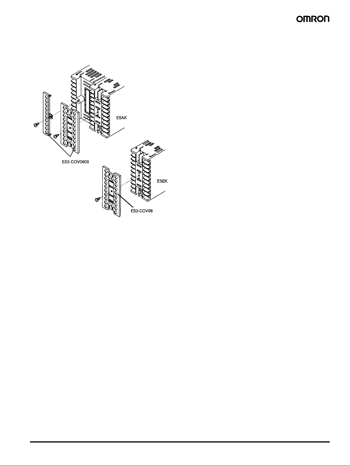
E53-COV0809, E53-COV08 Terminal Cover
(Sold Separately)
Fasten the terminals covers as follows by using the snap pins. Snap
pins are provided with the terminal covers.
Digital Controller E5AK/E5EK 11
 Loading...