

Omron E5*D User Manual
1
Introduction
2
Preparations
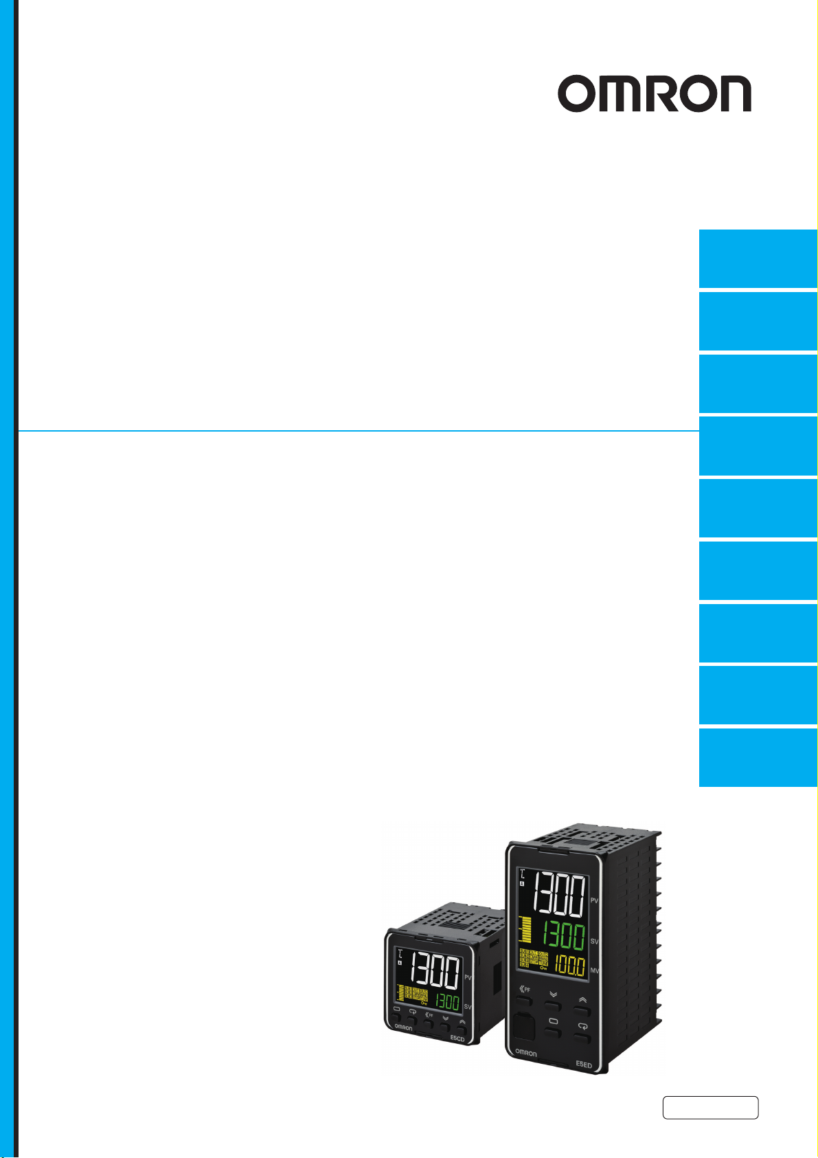
Digital Temperature Controllers
User’s Manual
E5@D
3
Part Names and
Basic Procedures
4
Basic
Operation
5
Advanced
Operations
6
Parameters
7
User Calibration
A
Appendices
I
Index
H224-E1-02


Preface
© OMRON, 2017
All rights reserved. No part of this publication may be reproduced, stored in a retrieval system or transmitted, in any form,
or by any means, mechanical, electronic, photocopying, recording, or otherwise, without the prior written permission of
OMRON.
No patent liability is assumed with respect to the use of the information contained herein. Moreover, because OMRON is
constantly striving to improve its high-quality products, the information contained in this manual is subject to change
without notice. Every precaution has been taken in the preparation of this manual. Nevertheless, OMRON assumes no
responsibility for errors or omissions. Neither is any liability assumed for damages resulting from the use of the
information contained in this publication.
Thank you for purchasing an E5@D Digital Controller.
This manual describes how to use the E5@D. Read this manual thoroughly and be sure you understand
it before attempting to use the Digital Controller and use the Digital Controller correctly according to the
information provided. Keep this manual in a safe place for easy reference. Refer to the E5
Controllers Communications Manual (Cat. No. H225) for information on communications.
Preface
@
D Digital
E5@D Digital Temperature Controllers User’s Manual (H224)
1

Terms and Conditions Agreement
Terms and Conditions Agreement
Warranty, Limitations of Liability
Warranties
Exclusive Warranty
Omron’s exclusive warranty is that the Products will be free from defects in materials and
workmanship for a period of twelve months from the date of sale by Omron (or such other period
expressed in writing by Omron). Omron disclaims all other warranties, express or implied.
Limitations
OMRON MAKES NO WARRANTY OR REPRESENTATION, EXPRESS OR IMPLIED, ABOUT
NON-INFRINGEMENT, MERCHANTABILITY OR FITNESS FOR A PARTICULAR PURPOSE OF
THE PRODUCTS. BUYER ACKNOWLEDGES THAT IT ALONE HAS DETERMINED THAT THE
PRODUCTS WILL SUITABLY MEET THE REQUIREMENTS OF THEIR INTENDED USE.
Omron further disclaims all warranties and responsibility of any type for claims or expenses based
on infringement by the Products or otherwise of any intellectual property right.
Buyer Remedy
Omron’s sole obligation hereunder shall be, at Omron’s election, to (i) replace (in the form originally
shipped with Buyer responsible for labor charges for removal or replacement thereof) the
non-complying Product, (ii) repair the non-complying Product, or (iii) repay or credit Buyer an
amount equal to the purchase price of the non-complying Product; provided that in no event shall
Omron be responsible for warranty, repair, indemnity or any other claims or expenses regarding the
Products unless Omron’s analysis confirms that the Products were properly handled, stored,
installed and maintained and not subject to contamination, abuse, misuse or inappropriate
modification. Return of any Products by Buyer must be approved in writing by Omron before
shipment. Omron Companies shall not be liable for the suitability or unsuitability or the results from
the use of Products in combination with any electrical or electronic components, circuits, system
assemblies or any other materials or substances or environments. Any advice, recommendations or
information given orally or in writing, are not to be construed as an amendment or addition to the
above warranty.
See http://www.omron.com/global/ or contact your Omron representative for published information.
Limitation on Liability; Etc
OMRON COMPANIES SHALL NOT BE LIABLE FOR SPECIAL, INDIRECT, INCIDENTAL, OR CONSEQUENTIAL DAMAGES, LOSS OF PROFITS OR PRODUCTION OR COMMERCIAL LOSS IN ANY
WAY CONNECTED WITH THE PRODUCTS, WHETHER SUCH CLAIM IS BASED IN CONTRACT,
WARRANTY, NEGLIGENCE OR STRICT LIABILITY.
Further, in no event shall liability of Omron Companies exceed the individual price of the Product on
which liability is asserted.
2
E5@D Digital Temperature Controllers User’s Manual (H224)

Application Considerations
Suitability of Use
Omron Companies shall not be responsible for conformity with any standards, codes or regulations
which apply to the combination of the Product in the Buyer’s application or use of the Product. At
Buyer’s request, Omron will provide applicable third party certification documents identifying ratings
and limitations of use which apply to the Product. This information by itself is not sufficient for a complete determination of the suitability of the Product in combination with the end product, machine, system, or other application or use. Buyer shall be solely responsible for determining appropriateness of
the particular Product with respect to Buyer’s application, product or system. Buyer shall take application responsibility in all cases.
NEVER USE THE PRODUCT FOR AN APPLICATION INVOLVING SERIOUS RISK TO LIFE OR
PROPERTY WITHOUT ENSURING THAT THE SYSTEM AS A WHOLE HAS BEEN DESIGNED TO
ADDRESS THE RISKS, AND THAT THE OMRON PRODUCT(S) IS PROPERLY RATED AND
INSTALLED FOR THE INTENDED USE WITHIN THE OVERALL EQUIPMENT OR SYSTEM.
Terms and Conditions Agreement
Programmable Products
Omron Companies shall not be responsible for the user’s programming of a programmable Product, or
any consequence thereof.
Disclaimers
Performance Data
Data presented in Omron Company websites, catalogs and other materials is provided as a guide for
the user in determining suitability and does not constitute a warranty. It may represent the result of
Omron’s test conditions, and the user must correlate it to actual application requirements. Actual performance is subject to the Omron’s Warranty and Limitations of Liability.
Change in Specifications
Product specifications and accessories may be changed at any time based on improvements and other
reasons. It is our practice to change part numbers when published ratings or features are changed, or
when significant construction changes are made. However, some specifications of the Product may be
changed without any notice. When in doubt, special part numbers may be assigned to fix or establish
key specifications for your application. Please consult with your Omron’s representative at any time to
confirm actual specifications of purchased Product.
Errors and Omissions
Information presented by Omron Companies has been checked and is believed to be accurate; however, no responsibility is assumed for clerical, typographical or proofreading errors or omissions.
E5@D Digital Temperature Controllers User’s Manual (H224)
3
Safety Precautions
Safety Precautions
Definition of Precautionary Information
The following notation is used in this manual to provide precautions required to ensure safe usage of
the E5@D Digital Controllers.
The safety precautions that are provided are extremely important to safety. Always read and heed the
information provided in all safety precautions.
The following notation is used.
Indicates a potentially hazardous situation which, if not avoided,
CAUTION
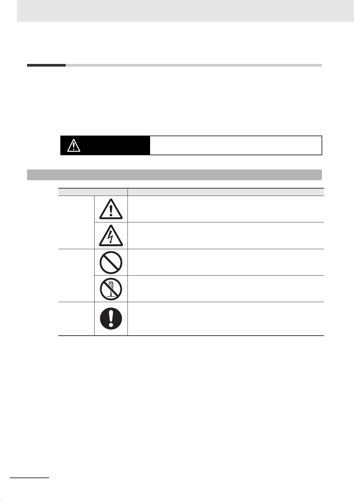
Symbols
may result in minor or moderate injury or in property damage.
Symbol Meaning
Caution
Prohibition
Mandatory
Caution
General Caution
Indicates non-specific general cautions, warnings, and dangers.
Electrical Shock Caution
Indicates possibility of electric shock under specific conditions.
General Prohibition
Indicates non-specific general prohibitions.
Disassembly Prohibition
Indicates prohibitions when there is a possibility of injury, such as from electric
shock, as the result of disassembly.
General Caution
Indicates non-specific general cautions, warnings, and dangers.
4
E5@D Digital Temperature Controllers User’s Manual (H224)
Safety Precautions
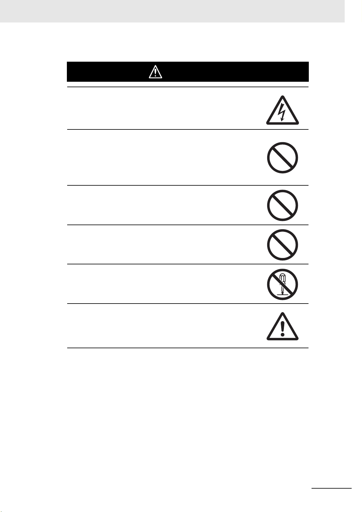
CAUTION
Minor injury due to electric shock may occasionally occur.
Do not touch the terminals while power is being supplied.
Electric shock, fire, or malfunction may occasionally occur.
Do not allow metal objects, conductors, debris (such as cuttings)
from installation work, moisture, or other foreign matter to enter the
Digital Controller, the Setup Tool ports, or between the pins on the
connectors on the Setup Tool cable.
Attach the cover to the front-panel Setup Tool port whenever you
are not using it to prevent foreign objects from entering the port.
Safety Precautions
Minor injury from explosion may occasionally occur.
Do not use the product where subject to flammable or explosive gas.
Minor electric shock or fire may occasionally occur.
Do not use a Digital Controller or cable that is damaged.
Minor electric shock, fire, or malfunction may occasionally occur.
Never disassemble, modify, or repair the product or touch any of the
internal parts.
If the output relays are used past their life expectancy, contact fusing
or burning may occasionally occur.
Always consider the application conditions and use the output relays
within their rated load and electrical life expectancy. The life
expectancy of output relays varies considerably with the output load
and switching conditions.
E5@D Digital Temperature Controllers User’s Manual (H224)
5
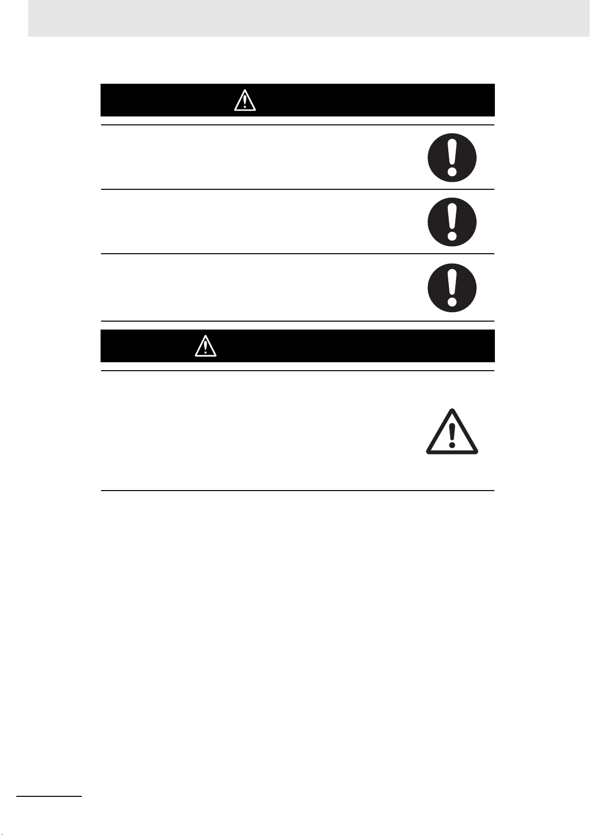
Safety Precautions
Loose screws may occasionally result in fire.
Tighten the terminal screws to the specified torque of 0.43 to
0.58 N·m.
Set the parameters of the product so that they are suitable for the
system being controlled. If they are not suitable, unexpected
operation may occasionally result in property damage or accidents.
A malfunction in the Digital Controller may occasionally make control
operations impossible or prevent alarm outputs, resulting in property
damage. To maintain safety in the event of malfunction of the Digital
Controller, take appropriate safety measures, such as installing a
monitoring device on a separate line.
CAUTION
Safety Standards
CAUTION - Risk of Fire and Electric Shock
(a) This product is UL listed as Open Type Process Control
Equipment. It must be mounted in an enclosure that does not
allow fire to escape externally.
(b) More than one disconnect switch may be required to
de-energize the equipment before servicing.
(c) Signal inputs are SELV, limited energy.
(d) Caution: To reduce the risk of fire or electric shock, do not
interconnect the outputs of different Class 2 circuits.
*1 An SELV (separated extra-low voltage) system is one with a power supply that has double or reinforced
insulation between the primary and the secondary circuits and has an output voltage of 30 V r.m.s. max.
and 42.4 V peak max. or 60 VDC max.
*2 A class 2 circuit is one tested and certified by UL as having the current and voltage of the secondary output
restricted to specific levels.
*1
*2
6
E5@D Digital Temperature Controllers User’s Manual (H224)
Precautions for Safe Use
Be sure to observe the following precautions to prevent operation failure, malfunction, or adverse
affects on the performance and functions of the product. Not doing so may occasionally result in unexpected events. Do not handle the Digital Controller in ways that exceed the ratings.
( 1) The product is designed for indoor use only. Do not use or store the product outdoors or in any of
the following places.
Places directly subject to heat radiated from heating equipment.
Places subject to splashing liquid or oil atmosphere.
Places subject to direct sunlight.
Places subject to dust or corrosive gas (in particular, sulfide gas and ammonia gas).
Places subject to intense temperature change.
Places subject to icing and condensation.
Places subject to vibration and large shocks.
( 2) Use and store the Digital Controller within the rated ambient temperature and humidity.
Gang-mounting two or more Digital Controllers, or mounting Digital Controllers above each other
may cause heat to build up inside the Digital Controllers, which will shorten their service life. In
such a case, use forced cooling by fans or other means of air ventilation to cool down the Digital
Controllers.
( 3) To allow heat to escape, do not block the area around the Digital Controller. Do not block the ven-
tilation holes on the Digital Controller.
( 4) Always check the terminal names and polarity and be sure to wire properly.
( 5) To connect bare wires, use copper stranded or solid wires.
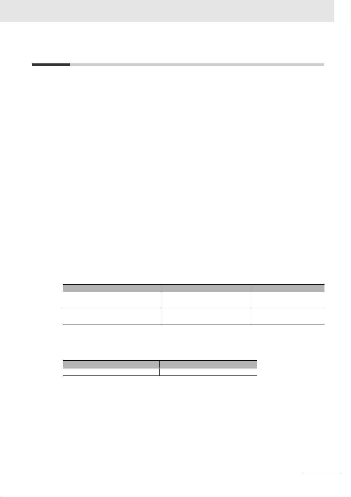
Use the wire sizes and stripping lengths given in the following table to prevent smoking and firing
of the wiring material.
Precautions for Safe Use
Recommended Wires
Model Recommended wires Stripping length
E5CD or E5ED AWG24 to AWG18
(0.205 to 0.823 mm
E5@D-B
(Push-In Plus terminal blocks)
0.25 to 1.5 mm
(equivalent to AWG24 to AWG16)
2
2
)
6 to 8 mm
Without ferrules: 8 mm
Use the specified size of crimped terminals to wire the E5CD or E5ED.
Crimp Terminal Sizes
Model Crimp terminal size
E5CD or E5ED M3, Width: 5.8 mm max.
For the E5@D-B (models with Push-In Plus terminal blocks), connect only one wire to each terminal.
For the E5CD or E5ED (models with screw terminals), you can connect up to two wires of the same
size and type, or two crimped terminals, to a single terminal.
( 6) Do not wire the terminals that are not used.
E5@D Digital Temperature Controllers User’s Manual (H224)
7

Precautions for Safe Use
( 7 ) To avoid inductive noise, keep the wiring for the Digital Controller's terminal block away from
power cables that carry high voltages or large currents. Also, do not wire power lines together with
or parallel to Digital Controller wiring. Using shielded cables and using separate conduits or ducts
is recommended.
Attach a surge suppressor or noise filter to peripheral devices that generate noise (in particular,
motors, transformers, solenoids, magnetic coils or other equipment that have an inductance component).
When a noise filter is used at the power supply, first check the voltage or current, and attach the
noise filter as close as possible to the Digital Controller.
Allow as much space as possible between the Digital Controller and devices that generate power-
ful high frequencies (high-frequency welders, high-frequency sewing machines, etc.) or surge.
( 8) Use the Digital Controller within the rated load and power supply.
( 9 ) Make sure that the rated voltage is attained within 2 seconds of turning ON the power using a
switch or relay contact. If the voltage is applied gradually, the power may not be reset or output
malfunctions may occur.
(10) Make sure that the Digital Controller has 30 minutes or more to warm up after turning ON the
power before starting actual control operations to ensure the correct temperature display.
(11) When using adaptive control, turn ON power for the load (e.g., heater) at the same time as or
before supplying power to the Digital Controller. If power is turned ON for the Digital Controller
before turning ON power for the load, tuning will not be performed properly and optimum control
will not be achieved.
(12) During tuning,* ensure that the power for the load (e.g., heater) is ON. If the power supply to the
load (e.g., heater) is not turned ON during tuning, tuning results will not be calculated correctly and
it will not be possible to achieve optimum control.
* “Tuning” refers to the following functions: AT, adaptive control, automatic filter adjustment, and
water-cooling output adjustment.
(13) A switch or circuit breaker must be provided close to Digital Controller. The switch or circuit
breaker must be within easy reach of the operator, and must be marked as a disconnecting means
for Digital Controller.
(14) Wipe off any dirt from the Digital Controller with a soft dry cloth. Never use thinners, benzine, alco-
hol, or any cleaners that contain these or other organic solvents. Deformation or discoloration may
occur.
(15) Design the system (e.g., control panel) considering the 2 seconds of delay in setting the Digital
Controller’s output after the power supply is turned ON.
(16) The output will turn OFF when you move to the Initial Setting Level. Take this into consideration
when performing control.
(17) The number of non-volatile memory write operations is limited. Therefore, use RAM write mode
when frequently overwriting data, e.g., through communications.
(18) Always touch a grounded piece of metal before touching the Digital Controller to discharge static
electricity from your body.
(19) Use suitable tools when taking the Digital Controller apart for disposal. Sharp parts inside the Dig-
ital Controller may cause injury.
(20) Install the DIN Track vertically to the ground.
8
E5@D Digital Temperature Controllers User’s Manual (H224)

Precautions for Safe Use
(21) Observe the following precautions when drawing out the body of the Digital Controller.
• Follow the procedure given in 2-1-4 Drawing Out the Interior Body of the Digital Controller to
Replace It on page 2-7 of this manual.
• Turn OFF the power supply before you start and never touch nor apply shock to the terminals or
electric components.
When connecting or disconnecting the Main Unit, do not allow the electronic components to touch
the rear case.
• When you insert the interior body into the rear case, confirm that the hooks on the top and bottom
are securely engaged with the case.
• If the terminals are corroded, replace the rear case as well
(22) For the power supply voltage input, use a commercial power supply with an AC input. Do not use
the output from an inverter as the power supply. Depending on the output characteristics of the
inverter, temperature increases in the product may cause smoke or fire damage even if the prod-
uct has a specified output frequency of 50/60 Hz.
(23) Do not continue to use the Digital Controller if the front surface peels.
(24) Do not exceed the communications distance that is given in the specifications and use the speci-
fied communications cable.
(25) Do not turn the power supply to the Digital Controller ON or OFF while the USB-Serial Conversion
Cable is connected. The Digital Controller may malfunction.
(26) Do not place heavy objects on top of the USB-Serial Conversion Cable, bend the Cable beyond its
natural bending limit, or pull on the Cable. Doing so may result in failure.
(27) Make sure that the indicators on the USB-Serial Conversion Cable are operating properly.
Depending on the application conditions, deterioration in the connectors and cable may be accel-
erated, and normal communications may become impossible. Perform periodic inspection and
replacement.
(28) Do not disconnect the USB-Serial Conversion Cable while communications are in progress. The
Digital Controller may be damaged or may malfunction.
(29) Connectors may be damaged if they are inserted with excessive force. When connecting a con-
nector, always make sure that it is oriented correctly. Do not force the connector if it does not con-
nect smoothly.
(30) Do not touch the external power supply terminals or other metal parts of the cables on the Digital
Controller.
(31) Noise may enter on the USB-Serial Conversion Cable, possibly causing equipment malfunctions.
Do not leave the USB-Serial Conversion Cable connected constantly to the equipment.
(32) With the E5ED/E5ED-B, do not connect cables to both the front-panel Setup Tool port and the
top-panel Setup Tool port at the same time. The Digital Controller may be damaged or may mal-
function.
(33) Observe the following precautions when wiring the E5@D-B.
• Follow the procedures given in E5@D-B (Models with Push-In Plus Terminal Blocks) on page 2-25
of this manual.
• Do not wire anything to the release holes.
• Do not tilt or twist a flat-blade screwdriver while it is inserted into a release hole on the terminal
block. The terminal block may be damaged.
• Insert a flat-blade screwdriver into the release holes at an angle. The terminal block may be
damaged if you insert the screwdriver straight in.
• Do not allow the flat-blade screwdriver to fall out while it is inserted into a release hole.
• Do not bend a wire past its natural bending radius or pull on it with excessive force. Doing so may
cause the wire to break.
• Do not use crossover wiring except for the input power supply and communications.
E5@D Digital Temperature Controllers User’s Manual (H224)
9

Precautions for Correct Use
Precautions for Correct Use
Service Life
( 1) Use the Digital Controller within the following temperature and humidity ranges:
Temperature: −10 to 55°C (with no icing or condensation), Humidity: 25% to 85%
If the Digital Controller is installed inside a control board, the ambient temperature must be kept to
under 55°C, including the temperature around the Digital Controller.
( 2 ) The service life of electronic devices like Digital Controllers is determined not only by the number
of times the relay is switched but also by the service life of internal electronic components. Component service life is affected by the ambient temperature: the higher the temperature, the shorter
the service life and, the lower the temperature, the longer the service life. Therefore, the service
life can be extended by lowering the temperature of the Digital Controller.
( 3 ) When two or more Digital Controllers are mounted horizontally close to each other or vertically
next to one another, the internal temperature will increase due to heat radiated by the Digital Controllers and the service life will decrease. In such a case, use forced cooling by fans or other
means of air ventilation to cool down the Digital Controllers. When providing forced cooling, however, be careful not to cool down the terminals sections alone to avoid measurement errors.
Ensuring Measurement Accuracy
( 1 ) When extending or connecting the thermocouple lead wire, be sure to use compensating wires
that match the thermocouple types.
( 2 ) When extending or connecting the lead wire of the platinum resistance thermometer, be sure to
use wires that have low resistance and keep the resistance of the three lead wires the same.
( 3) Mount the Digital Controller so that it is horizontally level.
( 4) If the measurement accuracy is low, check to see if input shift has been set correctly.
Resistance to Water
The degree of protection is as shown below. Sections without any specification on their degree of
protection or those with IP@0 are not waterproof.
Front panel: IP66
Rear case: IP20, Terminal section: IP00
When waterproofing is required, insert the Waterproof Packing on the backside of the front panel.
Keep the Port Cover on the front-panel Setup Tool port of the E5ED or E5ED-B securely closed.
The degree of protection when the Waterproof Packing is used is IP66. To maintain an IP66 degree
of protection, the Waterproof Packing and the Port Cover for the front-panel Setup Tool port must be
periodically replaced because they may deteriorate, shrink, or harden depending on the operating
environment. The replacement period will vary with the operating environment. Check the required
period in the actual application. Use 3 years or sooner as a guideline. If the Waterproof Packing and
Port Cover are not periodically replaced, waterproof performance may not be maintained.
If a waterproof structure is not required, then the Waterproof Packing does not need to be installed.
10
E5@D Digital Temperature Controllers User’s Manual (H224)

Precautions for Correct Use
Precautions during Operation
( 1 ) It takes approximately two seconds for the outputs to turn ON from after the power supply is
turned ON. Design the system (e.g., control panel) to allow for this delay.
( 2 ) Make sure that the Digital Controller has 30 minutes or more to warm up after turning ON the
power before starting actual control operations to ensure the correct temperature display.
( 3 ) Avoid using the Digital Controller in places near a radio, television set, or wireless installing. The
Digital Controller may cause radio disturbance for these devices.
Others
( 1 ) Do not rapidly and repeatedly insert and disconnect the USB connector on the USB-Serial Con-
version Cable. The computer may operate incorrectly.
( 2 ) The personal computer requires time to recognize the cable connection after the USB connector is
connected to the personal computer. This delay does not indicate failure. Check the COM port
number before starting communications.
( 3 ) Do not connect to a personal computer through a USB hub. The USB-Serial Conversion Cable
may malfunction.
( 4 ) Do not extend the USB cable with an extension cable to connect to the personal computer. The
USB-Serial Conversion Cable may malfunction.
E5@D Digital Temperature Controllers User’s Manual (H224)
11

Preparations for Use
Preparations for Use
Be sure to thoroughly read and understand the manual provided with the product, and check the following points.
Timing Check point Details
Purchasing
the product
Setting the
Unit
Wiring Terminal wiring Do not subject the terminal screws to excessive stress (force) when
Operating
environment
Product
appearance
Product model and
specifications
Product installation
location
Power supply
inputs
Ambient
temperature
Vibration and
shock
Foreign particles Install the product in a location that is not subject to liquid or foreign
After purchase, check that the product and packaging are not dented or
otherwise damaged. Damaged internal parts may prevent optimum control.
Make sure that the purchased product meets the required specifications.
Provide sufficient space around the product for heat dissipation. Do not
block the vents on the product.
tightening them.
Make sure that there are no loose screws after tightening terminal screws to
the specified torque of 0.43 to 0.58 N·m.
Be sure to confirm the polarity for each terminal before wiring the terminal
block and connectors.
For the E5
to wire anything to the release holes.
For the E5
wiring only for the input power supply and communications. Do not exceed
the maximum number of Digital Controllers given below if you use crossover
wiring for the input power supply.
100 to 240 VAC Controllers: 16 max.
24 VAC/VDC Controllers: 8 max.
Wire the power supply inputs correctly. Incorrect wiring will result in damage
to the internal circuits.
The ambient operating temperature for the Digital Controller is −10 to 55°C
(with no condensation or icing).
To extend the service life of the product, install it in a location with an
ambient temperature as low as possible. In locations exposed to high
temperatures, if necessary, cool the products using a fan or other cooling
method.
Check whether the standards related to shock and vibration are satisfied at
the installation environment. (Install the product in locations where the
contactors will not be subject to vibration or shock.)
particles entering the product.
@D-B (models with Push-In Plus terminal blocks), do not attempt
@D-B (models with Push-In Plus terminal blocks), use crossover
12
E5@D Digital Temperature Controllers User’s Manual (H224)

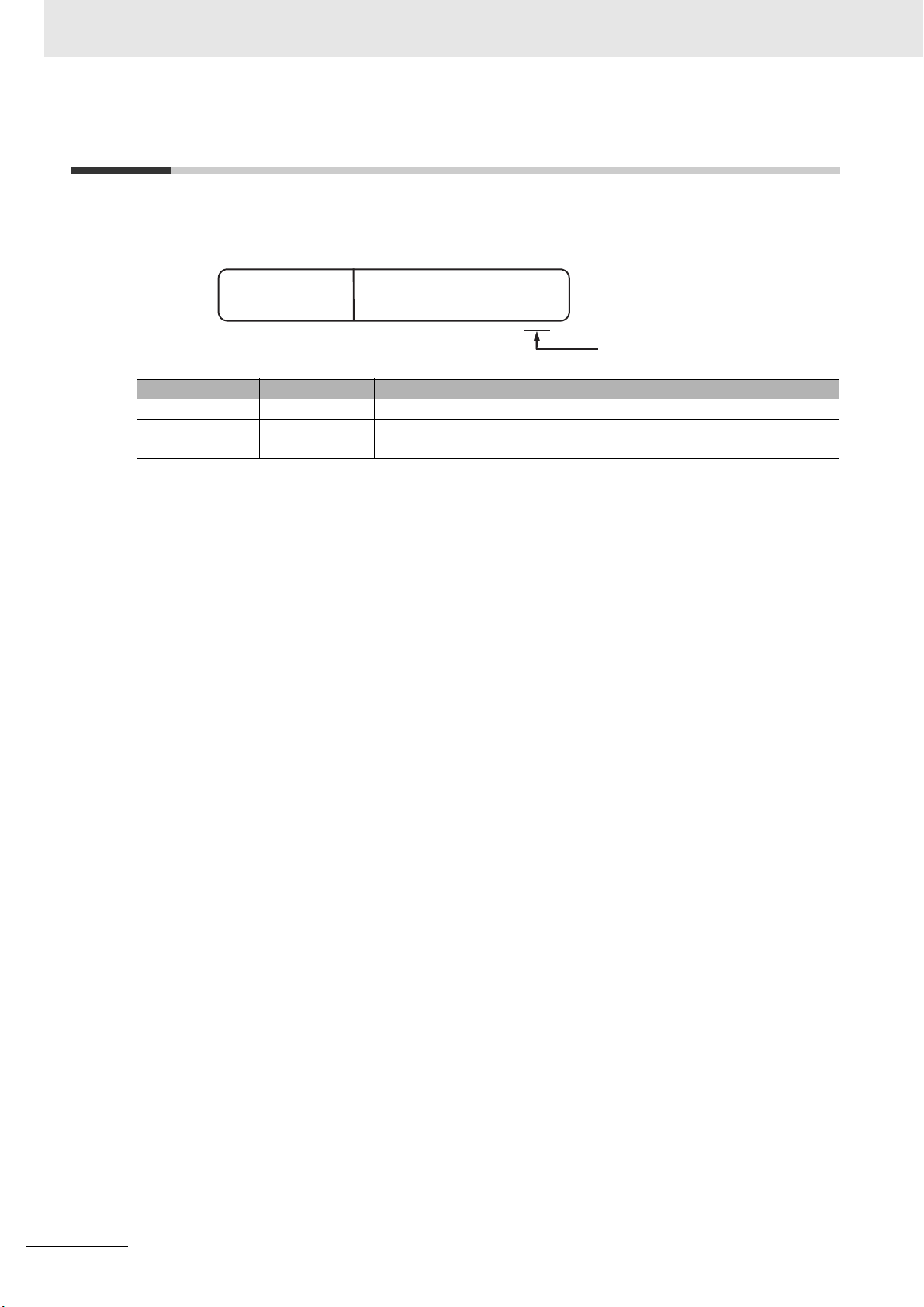
Versions
8
E5CD-RX2A6M-000
DIGITAL CONTROLLER
Ver1.0
The version is given here.
The version is given here.
Check the version on the nameplate on the E5@D Digital Controller or on the label on the packing box.
Versions
Product nameplate Package label
E5@D Digital Temperature Controllers User’s Manual (H224)
13
Revision History
H224-E1-02
Revision code
Cat. No.
Revision History
A manual revision code appears as a suffix to the catalog number on the front cover of the manual.
Revision code Date Revised content
01 March 2017 Original production
02 October 2017 • Added E5CD-B and E5ED-B.
• Added models with linear current outputs.
14
E5@D Digital Temperature Controllers User’s Manual (H224)
Conventions Used in This Manual
000
MASK
MASK8
Conventions Used in This Manual
Model Notation
“E5@D” is used to indicate information that is the same for the E5CD and E5ED Digital Controllers.
“E5@D-B” is used to indicate information that is the same for the E5CD-B and E5ED-B Digital Controllers.
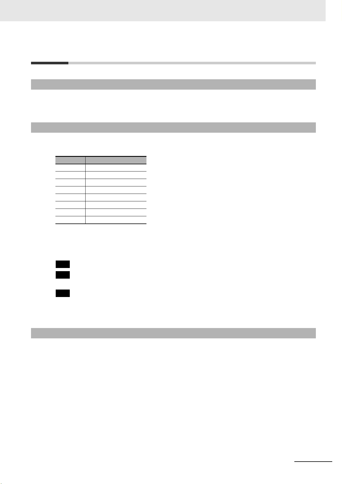
Meanings of Abbreviations
The following abbreviations are used in parameter names, figures, and other descriptions. These
abbreviations mean the following:
Symbol Term
PV Process value
SP Set point
SV Set value
AT Auto-tuning
EU Engineering unit*
LBA Loop burnout alarm
HB Heater burnout
HS Heater short
* “EU” stands for Engineering Unit. EU is used as the minimum unit for engineering units such as °C, m, and g.
The size of the EU depends on the input type. For example, when the input temperature setting range is −200
to 1,300°C, 1 EU is 1°C, and when the input temperature setting range is −20.0 to 500.0°C, 1 EU is 0.1°C.
For analog inputs, the size of the EU depends on the decimal point position of the scaling setting, and 1 EU is
the minimum scaling unit.
: Functions with this mark can be used only with the E5@D-@-0@@.
: Parameters with this mark can be used with either the E5@D-@-0@@ or E5@D-@-8@@, but they
are masked with the default settings.
: Parameters with this mark can be used with the E5@D-@-8@@, but they are masked with the
default settings.
Refer to 5-12 Hiding and Displaying Parameters on page 5-46 for information on displaying parameters
that are masked.
Terminology
The following term definitions are used in this manual.
system: The control loop, including the Digital Controller.
system fluctuations: Fluctuations in the temperature inside and outside the control loop.
Examples: Deterioration in heaters or other equipment
Seasonal changes in the ambient temperature
E5@D Digital Temperature Controllers User’s Manual (H224)
15
Conventions Used in This Manual
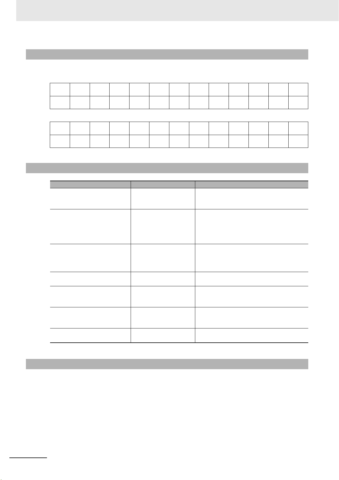
How to Read Display Symbols
The following tables show the correspondence between the symbols displayed on the displays and
alphabet characters.
abcdefghijklm
ABCDEFGH I JKLM
nopqrstuVwxyz
NOPQRS T UVWXY Z
How This Manual is Organized
Goal Related sections Contents
Learning about the
appearance, features,
functions, and model numbers
Setting up the E5@D Section 2 Preparations This section describes the steps that are
Learning the basic procedures
from turning ON the power
supply to starting actual
operation
Learning the basic operating
methods
Learning advanced operating
methods
Calibrating the E5@D Section 7 User Calibration This section describes the procedures that you
Learning the specifications
and parameters of the E5@D
Section 1 Introduction ---
required before turning ON the power supply
(including installation, terminal usage, wiring,
and isolation/insulation block diagram). It also
describes how to use the Setup Tool ports.
Section 3 Part Names and
Basic Procedures
Section 4 Basic Operation
Section 6 Parameters
Section 5 Advanced
Operations
Section 6 Parameters
Appendices ---
This section serves as a basic tutorial for
first-time users of the E5@D.
These sections describe basic operating
methods.
These sections describe advanced operating
methods.
can use to calibrate the sensor or transfer
output of the E5@D.
Related Manuals
Also refer to the E5
communications.
16
@
D Digital Controllers Communications Manual (Cat. No. H225) for information on
E5@D Digital Temperature Controllers User’s Manual (H224)
1
2
3
4
5
6
7
1
2
3
4
5
6
7
Introduction
Preparations
Part Names and Basic Procedures
Basic Operation
Advanced Operations
Parameters
User Calibration
A
A
Appendices
I
I
Index
Sections in this Manual
Sections in this Manual
E5@D Digital Temperature Controllers User’s Manual (H224)
17

CONTENTS
CONTENTS
Preface .......................................................................................................................1
Terms and Conditions Agreement...........................................................................2
Warranty, Limitations of Liability ................................................................................................................... 2
Application Considerations ........................................................................................................................... 3
Disclaimers ................................................................................................................................................... 3
Safety Precautions.................................................................................................... 4
Definition of Precautionary Information ......................................................................................................... 4
Symbols ....................................................................................................................................................... 4
Precautions for Safe Use..........................................................................................7
Precautions for Correct Use...................................................................................10
Preparations for Use...............................................................................................12
Versions ...................................................................................................................13
Revision History......................................................................................................14
Conventions Used in This Manual.........................................................................15
Model Notation ............................................................................................................................................ 15
Meanings of Abbreviations .......................................................................................................................... 15
Terminology ................................................................................................................................................ 15
How to Read Display Symbols .................................................................................................................... 16
How This Manual is Organized ................................................................................................................... 16
Related Manuals ......................................................................................................................................... 16
Sections in this Manual ..........................................................................................17
Section 1 Introduction
1-1 Appearance, Features, and Functions of the E5@D............................................................. 1-2
1-1-1 Appearance.................................................................................................................................1-2
1-1-2 Features...................................................................................................................................... 1-2
1-1-3 Main Functions............................................................................................................................1-5
1-2 I/O Configuration and Model Number Legend ...................................................................... 1-7
1-2-1 I/O Configuration.........................................................................................................................1-7
1-2-2 Model Number Legends.............................................................................................................. 1-8
Section 2 Preparations
2-1 Installation................................................................................................................................ 2-2
2-1-1 Dimensions (Unit: mm)................................................................................................................2-2
2-1-2 Panel Cutout (Unit: mm).............................................................................................................. 2-4
2-1-3 Mounting ..................................................................................................................................... 2-5
2-1-4 Drawing Out the Interior Body of the Digital Controller to Replace It ..........................................2-7
2-2 Using the Terminals ................................................................................................................ 2-9
2-2-1 E5CD Terminal Block Wiring Example........................................................................................2-9
2-2-2 E5CD-B Terminal Block Wiring Example ..................................................................................2-13
2-2-3 E5ED Terminal Block Wiring Example......................................................................................2-17
2-2-4 E5ED-B Terminal Block Wiring Example .................................................................................. 2-21
2-2-5 Precautions when Wiring ..........................................................................................................2-25
2-2-6 Wiring........................................................................................................................................ 2-28
18
E5@D Digital Temperature Controllers User’s Manual (H224)

CONTENTS
2-3 Installing Temperature Sensors for Packing Machines ..................................................... 2-36
000
2-4 Insulation Block Diagrams ................................................................................................... 2-38
2-5 Using the Setup Tool Port ......................................................................................... 2-39
2-5-1 Procedure ................................................................................................................................. 2-39
2-5-2 Connection Method................................................................................................................... 2-39
2-5-3 Installing the Driver................................................................................................................... 2-42
Section 3 Part Names and Basic Procedures
3-1 Basic Flow of Operation ......................................................................................................... 3-2
3-2 Power ON ................................................................................................................................. 3-3
3-3 Part Names, Part Functions, and Setting Levels .................................................................. 3-4
3-3-1 Part Names and Functions ......................................................................................................... 3-4
3-3-2 Entering Numeric Values............................................................................................................ 3-7
3-3-3 Setting Levels ............................................................................................................................. 3-8
3-4 Procedures after Turning ON the Power Supply ................................................................ 3-11
3-4-1 Basic Flow of Operations.......................................................................................................... 3-11
3-4-2 Basic Procedure ....................................................................................................................... 3-11
Section 4 Basic Operation
4-1 Moving between Setting Levels ............................................................................................. 4-3
4-1-1 Moving to the Initial Setting Level............................................................................................... 4-3
4-1-2 Moving to the Adjustment Level.................................................................................................. 4-4
4-1-3 Moving to the Protect Level ........................................................................................................ 4-4
4-1-4 Moving to the Advanced Function Setting Level......................................................................... 4-5
4-1-5 Moving to the Communications Setting Level............................................................................. 4-7
4-2 Initial Setting Examples .......................................................................................................... 4-8
4-3 Setting the Input Type ........................................................................................................... 4-11
4-3-1 Input Type................................................................................................................................. 4-11
4-4 Selecting the Temperature Unit ........................................................................................... 4-13
4-4-1 Temperature Unit...................................................................................................................... 4-13
4-5 Selecting PID Control or ON/OFF Control ........................................................................... 4-14
4-6 Setting Output Specifications .............................................................................................. 4-15
4-6-1 Control Period........................................................................................................................... 4-15
4-6-2 Direct and Reverse Operation .................................................................................................. 4-15
4-6-3 Assigned Output Functions....................................................................................................... 4-16
4-6-4 Auxiliary Output Opening or Closing in Alarm .......................................................................... 4-19
4-7 Setting the Set Point (SP) ..................................................................................................... 4-20
4-7-1 Changing the SP....................................................................................................................... 4-20
4-8 Using ON/OFF Control .......................................................................................................... 4-21
4-8-1 ON/OFF Control........................................................................................................................ 4-21
4-8-2 Settings..................................................................................................................................... 4-22
4-9 Determining PID Constants (AT, Manual Setup) ................................................................ 4-24
4-9-1 AT (Auto-tuning) ....................................................................................................................... 4-24
4-9-2 RT (Robust Tuning) (Use with AT) ..........................................................................................4-27
4-9-3 Manual Setup............................................................................................................................ 4-29
4-10 Alarm Outputs........................................................................................................................ 4-31
4-10-1 Alarm Types.............................................................................................................................. 4-31
4-10-2 Alarm Values ............................................................................................................................ 4-34
4-11 Alarm Hysteresis ................................................................................................................... 4-37
4-11-1 Standby Sequence ................................................................................................................... 4-37
4-11-2 Alarm Latch............................................................................................................................... 4-38
E5@D Digital Temperature Controllers User’s Manual (H224)
19

CONTENTS
4-12 Using Heater Burnout (HB) and Heater Short (HS) Alarms ............................................... 4-39
4-12-1 HB Alarm................................................................................................................................... 4-39
4-12-2 HS Alarm................................................................................................................................... 4-41
4-12-3 Installing Current Transformers (CT) ........................................................................................4-43
4-12-4 Calculating Detection Current Values ....................................................................................... 4-44
4-12-5 Application Examples................................................................................................................4-44
4-13 Customizing the PV/SP Display ........................................................................................... 4-46
4-13-1 PV/SP Display Selections .........................................................................................................4-46
Section 5 Advanced Operations
5-1 Suppressing Temperature Variations When Using a Temperature Sensor for Packing
Machines (for Packing Machines).......................................................................................... 5-3
5-2 Automatically Adjusting a Water-cooling Output (for Water-cooled Extruders) ............... 5-7
5-3 Performing Adaptive Control................................................................................................ 5-11
5-3-1 Overview ...................................................................................................................................5-11
5-3-2 Application Methods for Adaptive Control .................................................................................5-19
5-4 Indication Data ....................................................................................................................... 5-21
5-5 Shifting Input Values............................................................................................................. 5-25
5-6 Setting Scaling Upper and Lower Limits for Analog Inputs .............................................. 5-27
5-7 Executing Heating/Cooling Control ..................................................................................... 5-29
5-7-1 Heating/Cooling Control............................................................................................................ 5-29
5-8 Using Event Inputs ................................................................................................................ 5-33
5-8-1 Event Input Settings..................................................................................................................5-33
5-8-2 How to Use the Multi-SP Function ............................................................................................ 5-33
5-8-3 Operation Commands Other than Multi-SP ..............................................................................5-35
5-9 Setting the SP Upper and Lower Limit Values.................................................................... 5-39
5-9-1 Set Point Limiter........................................................................................................................5-39
5-9-2 Setting.......................................................................................................................................5-40
5-10 Using the SP Ramp Function to Limit the SP Change Rate .............................................. 5-41
5-10-1 SP Ramp...................................................................................................................................5-41
5-11 Using the Key Protect Level .................................................................................................5-43
5-11-1 Protection..................................................................................................................................5-43
5-11-2 Entering the Password to Move to the Protect Level ................................................................ 5-44
5-12 Hiding and Displaying Parameters ...................................................................................... 5-46
5-12-1 Parameter Mask Setting............................................................................................................ 5-46
5-13 OR Output of Alarms ............................................................................................................. 5-49
5-13-1 Integrated Alarm........................................................................................................................5-49
5-14 Alarm Delays .......................................................................................................................... 5-51
5-14-1 Alarm Delays............................................................................................................................. 5-51
5-15 Loop Burnout Alarm.............................................................................................................. 5-53
5-15-1 Loop Burnout Alarm (LBA)........................................................................................................5-53
5-16 Performing Manual Control .................................................................................................. 5-56
5-16-1 Manual MV................................................................................................................................5-56
5-17 Using the Simple Program Function.................................................................................... 5-59
5-17-1 Simple Program Function.......................................................................................................... 5-59
5-17-2 Operation at the Program End..................................................................................................5-62
5-17-3 Application Example Using a Simple Program..........................................................................5-64
5-18 Output Adjustment Functions .............................................................................................. 5-65
5-18-1 Output Limits.............................................................................................................................5-65
5-18-2 MV at Stop ................................................................................................................................5-65
5-18-3 MV at PV Error..........................................................................................................................5-65
20
E5@D Digital Temperature Controllers User’s Manual (H224)

CONTENTS
5-19 Using the Extraction of Square Root Parameter ................................................................ 5-67
000
000
5-19-1 Extraction of Square Roots....................................................................................................... 5-67
5-20 Setting the Width of MV Variation ........................................................................................ 5-69
5-20-1 MV Change Rate Limit.............................................................................................................. 5-69
5-21 Setting the PF Key ................................................................................................................. 5-70
5-21-1 PF Setting (Function Key) ........................................................................................................ 5-70
5-22 Displaying PV/SV Status ....................................................................................................... 5-73
5-22-1 PV and SV Status Display Functions........................................................................................5-73
5-23 Logic Operations ........................................................................................................ 5-75
5-23-1 The Logic Operation Function (CX-Thermo) ............................................................................ 5-75
5-23-2 Using Logic Operations ............................................................................................................ 5-75
5-24 Initializing Settings ................................................................................................................ 5-84
5-25 Setting the Operating Status to Use When Power Is Turned ON...................................... 5-85
5-26 Using the Transfer Output for the Process Value, Set Point, or other Data ......... 5-86
5-26-1 Transfer Output Function.......................................................................................................... 5-86
Section 6 Parameters
6-1 Conventions Used in this Section ......................................................................................... 6-2
6-2 Protect Level ............................................................................................................................ 6-3
6-3 Operation Level ....................................................................................................................... 6-7
6-4 Adjustment Level................................................................................................................... 6-16
6-5 Monitor/Setting Item Level.................................................................................................... 6-37
6-6 Manual Control Level ............................................................................................................ 6-38
6-7 Initial Setting Level................................................................................................................ 6-40
6-8 Advanced Function Setting Level ........................................................................................ 6-62
6-9 Communications Setting Level ............................................................................................ 6-97
Section 7 User Calibration
7-1 User Calibration ....................................................................................................................... 7-2
7-2 Parameter Structure ................................................................................................................ 7-3
7-3 Thermocouple Calibration ...................................................................................................... 7-4
7-4 Resistance Thermometer Calibration .................................................................................... 7-7
7-5 Calibrating Analog Input ........................................................................................................ 7-9
7-6 Calibrating the Transfer Output ........................................................................................... 7-13
7-7 Checking Indication Accuracy ............................................................................................. 7-15
E5@D Digital Temperature Controllers User’s Manual (H224)
21

CONTENTS
Section A Appendices
000
000
000
A-1 Specifications ..........................................................................................................................A-2
A-1-1 Ratings........................................................................................................................................A-2
A-1-2 Characteristics ............................................................................................................................A-4
A-1-3 Rating and Characteristics of Options.........................................................................................A-5
A-1-4 Waterproof Packing.....................................................................................................................A-5
A-1-5 Setup Tool Port Cover for Front Panel
A-1-6 Draw-out Jig ................................................................................................................................A-7
A-2 Current Transformer (CT) .......................................................................................................A-8
A-2-1 Specifications ..............................................................................................................................A-8
A-2-2 Dimensions (Unit: mm)................................................................................................................A-8
A-3 USB-Serial Conversion Cable and Conversion Cable ............................................A-11
A-3-1 E58-CIFQ2 USB-Serial Conversion Cable................................................................................A-11
A-3-2 E58-CIFQ2-E Conversion Cable...............................................................................................A-12
A-4 Temperature Sensor for Packing Machines........................................................................A-13
A-4-1 Model Number Legend..............................................................................................................A-13
A-4-2 Dimensions ...............................................................................................................................A-14
A-4-3 Mounting Brackets ....................................................................................................................A-15
A-5 Error Displays ........................................................................................................................A-16
A-6 Troubleshooting ....................................................................................................................A-20
A-7 Parameter Operation Lists....................................................................................................A-23
A-7-1 Operation Level.........................................................................................................................A-23
A-7-2 Adjustment Level.......................................................................................................................A-24
A-7-3 Initial Setting Level ....................................................................................................................A-26
A-7-4 Manual Control Level ................................................................................................................A-30
A-7-5 Monitor/Setting Item Level ........................................................................................................A-30
A-7-6 Advanced Function Setting Level..............................................................................................A-30
A-7-7 Protect Level .............................................................................................................................A-35
A-7-8 Communications Setting Level..................................................................................................A-35
A-7-9 Initialization According to Parameter Changes .........................................................................A-36
A-8 Sensor Input Setting Range, Indication Range, Control Range........................................A-39
...........................................................................A-6
A-9 Setting Levels Diagram.........................................................................................................A-40
A-10 Parameter Flow ...........................................................................................................A-41
A-11 Parameter Flow (For E5@D-@-80@)......................................................................................A-43
Index ................................................................................................Index-1
22
E5@D Digital Temperature Controllers User’s Manual (H224)

Introduction
1-1 Appearance, Features, and Functions of the E5@D . . . . . . . . . . . . . . . . . . 1-2
1-1-1 Appearance . . . . . . . . . . . . . . . . . . . . . . . . . . . . . . . . . . . . . . . . . . . . . . . . . . . 1-2
1-1-2 Features . . . . . . . . . . . . . . . . . . . . . . . . . . . . . . . . . . . . . . . . . . . . . . . . . . . . . . 1-2
1-1-3 Main Functions . . . . . . . . . . . . . . . . . . . . . . . . . . . . . . . . . . . . . . . . . . . . . . . . . 1-5
1-2 I/O Configuration and Model Number Legend . . . . . . . . . . . . . . . . . . . . . . . 1-7
1-2-1 I/O Configuration . . . . . . . . . . . . . . . . . . . . . . . . . . . . . . . . . . . . . . . . . . . . . . . . 1-7
1-2-2 Model Number Legends . . . . . . . . . . . . . . . . . . . . . . . . . . . . . . . . . . . . . . . . . . 1-8
1
E5@D Digital Temperature Controllers User’s Manual (H224)
1 - 1
1 Introduction
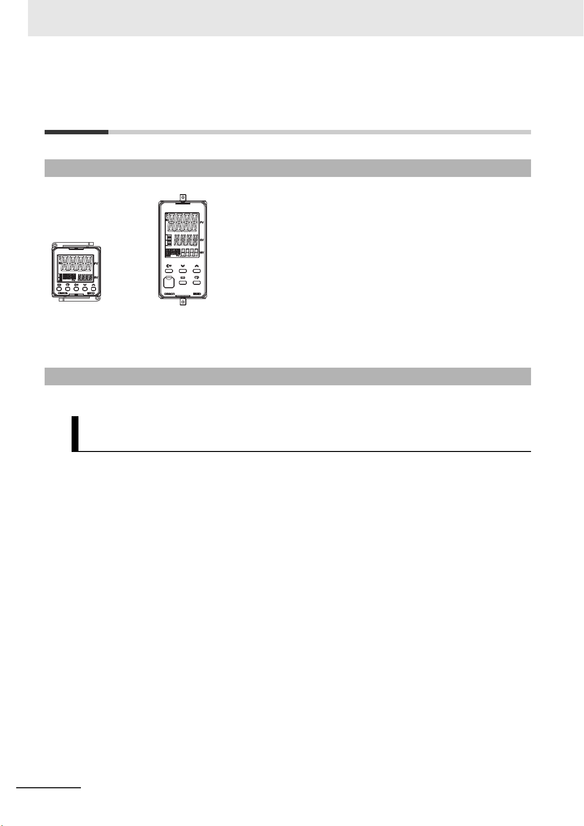
E5CD/E5CD-B E5ED/E5ED-B
1-1 Appearance, Features, and
Functions of the E5@D
1-1-1 Appearance
• Functions specialized for packaging machines.
• Functions specialized for water-cooled extruders.
• Automatic optimization of control for system fluctuations.*
• Displays of the heater current or manipulated value on a bar display.
• Various indication data.
• A stylish design that gives a new look to control panels.
• Large display characters and white backlight for better visibility.
• A compact size to help downsize control panels.
1-1-2 Features
The E5@D provides the following features.
Temperature Sensors for Packing Machines and Automatic Filter
Adjustment
Temperature Sensors for Packing Machines are available and automatic filter adjustment is supported.
Mainly, temperature variations in packing machines are suppressed to maintain stable performance.
Temperature Sensors for Packaging Machines
The temperature of a packing machine is normally controlled by measuring the temperature of a
heater that is separate from the sealing section. When that is done, a deviation occurs between the
temperature of the seal and the temperature of the heater, which can lead to sealing faults.
To solve this problem, OMRON provides Temperature Sensors for Packing Machines
(E52-CA@@A@ D=1 S@, sold separately) that can be used to measure the actual temperature of
the seal. You can use these Temperature Sensors to reduce the number of sealing faults caused by
this temperature deviation.
* system fluctuations: Fluctuations in the temperature inside and outside the
control loop.
Examples: Deterioration in heaters or other equipment
Seasonal changes in the ambient temperature
Automatic Filter Adjustment
When controlling the temperature of a packing machine, temperature variations can occur due to
periodic disturbances and other factors.
To handle this, you can use the automatic filter adjustment function in the Digital Controller to
suppress temperature variations caused by periodic disturbances and other factors.
Particularly if you use the above Temperature Sensors for Packing Machines, the affect of packing
material heat increases and the periodic temperature variation becomes apparent. Automatic filter
adjustment enables stable control.
We recommend that you use automatic filter adjustment in the following cases.
1 - 2
E5@D Digital Temperature Controllers User’s Manual (H224)

1 Introduction
• If temperature variation occurs when Temperature Sensors for Packing Machines are used even
if AT is performed
• If temperature variation occurs after a heater is replaced
• If temperature variation occurs after packing materials are changed or the packing speed is
changed
• If temperature variation occurs due to changes in the operating environment
Note: This function cannot be used during ON/OFF control or heating/cooling control.
1-1 Appearance, Features, and
Functions of the E5@D
1
Water-cooling Output Adjustment
Mainly, temperature variations in water-cooled extruders are suppressed to maintain stable performance.
When hunting occurs in heating/cooling control of water-cooled extruders, it was previously necessary
to have a worker skilled in PID adjustment or water-cooled valve adjustment adjust the system.
With water-cooling output adjustment, you can automatically adjust the cooling proportional band to
suppress temperature hunting. Because adjustment is performed during operation, optimum control is
enabled even during material condition changes.
We recommend that you use water-cooling output adjustment in the following cases.
• If temperature variation occurs due to changes in the water-cooling system
• If temperature variation occurs due to changes in the cooling valve settings
• To reduce the amount of work required to adjust cooling valves
Note: This function cannot be used during any of the following: standard control, an analog input type, any other
heating/cooling method (i.e., except for water cooling), direct operation, and SP ramp operation.
Adaptive Control
Adaptive control is a control method that helps to maintain optimum temperature control by following
any changes that may occur due to system fluctuations, such as changes in the environment or equipment deterioration.
With adaptive control, AT (auto-tuning) is required only the first time operation is performed. After that,
the equipment startup temperature is monitored to detect system fluctuations and update the PID constants for adaptive control.
There is no need to execute AT again or to manually adjust the PID constants, and higher control performance is achieved than is possible with AT alone.
1-1-2 Features
We recommend that you use adaptive control in the following cases.
• To reduce decline in control performance caused by environmental changes or equipment
deterioration
• To increase control performance over AT
Note: This function cannot be used during any of the following: heating/cooling control, an analog input type, direct
operation, and SP ramp operation.
Various Indication Data
Various indication data is provided to help predict the product service life and replacement period.
You can use it in the host system to collect and analyze data and make predictions.
E5@D Digital Temperature Controllers User’s Manual (H224)
1 - 3

1 Introduction
The following data can be read through host communications or checked with key operations on the
front panel.
• Power ON time data: You can display the total power ON time of the Digital Controller or read it with
• Ambient temperature
monitor:
• Output relay ON/OFF
count monitors:
communications.
The service life of the Digital Controller and equipment depends on the operating
environment.
You can collect power ON time data to clarify the relation between the operating
environment and service life and use it to predict future machine maintenance periods
and to improve the operating environment.
You can display the temperature around the terminals or read it with communications.
You can monitor trends in the ambient temperature to monitor for abnormal heat
generation in the panel.
The contacts in the relays have a service life. You can display the number of relay
ON/OFF operations or read it with communications.
You can monitor this data to determine replacement periods before the service life
count to make maintenance more efficient.
1 - 4
E5@D Digital Temperature Controllers User’s Manual (H224)

1-1-3 Main Functions
For details on particular functions and how to use them, refer to Section 3 Part Names and Basic Procedures and following sections.
Input Sensor Types
You can connect the following sensors and signals to the universal input.
1 Introduction
1-1 Appearance, Features, and
Functions of the E5@D
Thermocouple (temperature input): K, J, T, E, L, U, N, R, S, B, C/W, or PL II
Resistance thermometer (temperature input): Pt100, JPt100
Infrared Temperature Sensor (temperature input): ES1B
10 to 70°C, 60 to 120°C, 115 to 165°C, 140 to 260°C
Current input (analog input): 4 to 20 mA DC, 0 to 20 mA DC
Voltage input (analog input): 1 to 5 VDC, 0 to 5 V DC, 0 to 10 V DC
Control Outputs
• A control output can be a relay output, voltage output (for driving SSR), or linear current output,
depending on the model.
Adjusting PID Constants
• You can easily set the optimum PID constants by performing AT (auto-tuning) with the limit cycle
method.
• You can also add RT (robust tuning) to give priority to controlling stability.
Alarms
Standard Alarms
• You can output an alarm when the deviation, process value, set point, or manipulated value
reaches a specified value.
• You can also output alarms for the PV rate of change and for loop burnouts.
• If necessary, a more comprehensive alarm function can be achieved by setting a standby
sequence, alarm hysteresis, auxiliary output close in alarm/open in alarm, alarm latch, alarm ON
delay, and alarm OFF delay.
1
1-1-3 Main Functions
HB and HS Alarms
• With models with the optional HB and HS alarms, you can detect heater burnout and heater short
alarms based on CT inputs.
Integrated Alarm
• You can output an integrated alarm if a standard alarm, HB alarm, or HS alarm turns ON.
E5@D Digital Temperature Controllers User’s Manual (H224)
1 - 5

1 Introduction
Event Inputs
• With any model that supports event inputs, you can use external contact or transistor inputs to
achieve any of the following functions: Switching set points (Multi-SP No. Switch, 8 points max.),
switching RUN/STOP, switching between automatic and manual operation, starting/resetting the
program, inverting direct/reverse operation, 100% AT execute/cancel, 40% AT execute/cancel,
setting change enable/disable, communications write enable/disable, canceling the alarm latch,
PID updating (adaptive control), automatic filter adjustment, and water-cooling output adjustment.
Communications Functions
With any model that supports communications, you can use communications via CompoWay/F,
Modbus-RTU,* or programless communications.
* Modbus is a registered trademark of Schneider Electric.
Transfer Output
With any model that provides a transfer output, you can output the set point, process value,
manipulated variable, or other values as a 4 to 20 mA or 1 to 5 V transfer output.
1 - 6
E5@D Digital Temperature Controllers User’s Manual (H224)
 Loading...