

Page 1
Digital Controller E5AX-LA/-MA
A 96 x 96-mm (DIN) Digital Process
Controller
Optimum PID control with feed-forward control
circuitry.
High accuracy (+0.3% FS +1 digit max.).
Replaceable Output Units.
Models with communications capabilities also
available.
Ordering Information
Digital Controller
Communications None RS-232C RS-422* RS-485* BCD Transmission
output*/**
(4 to 20 mA)
Communica-
tions Board
Add-on type
Model E5AX-
L(M)A
*The Controller can also be equipped with a terminal block to connect communications. Specify a terminal block by adding “-X” to the model
number. Example: E5AX-LA02-X
**Capable of transmitting the process value or output value, but remote setting by external input is not possible.
E5AXL(M)A01
E5AXL(M)A02
E5AXL(M)A03
E5AXL(M)A20
E5AX-L(M)AF E5AX-L(M)AM
Control Output Units
Output Relay output SSR output Voltage output (for driving SSR) Current output
Model E53-R E53-S E53-Q E53-C
Control Input
Model E5AX-LA E5AX-MA
Input (switch
selectable)
Input range 4 to 20 mA 0 to 20 mA 1 to 5 V 0 to 5 V 0 to 1 V 0 to 100 mV 0 to 10 mV –10 to 10 mV
Setting 0 1 2 3 4 0 1 2
Current Voltage Voltage
Communications Boards
Communications RS-232C RS-422 RS-485 BCD Transmission
Model E53-X01 E53-X02 E53-X03 E53-X20 E53-XF
output
(4 to 20 mA)
1
Page 2
E5AX-LA/-MA
E5AX-LA/-MA
Specifications
Digital Controller Ratings
Supply voltage 100 to 240 VAC, 50/60 Hz (either frequency applicable with same unit)
Operating voltage range 85% to 110% of rated supply voltage
Power consumption Approx. 10 VA (at 100 VAC) to 15 VA (at 240 VAC)
Input E5AX-LA: 4 to 20 mA, 0 to 20 mA, 1 to 5 V, 0 to 5 V, 0 to 1 V
Input impedance Current input: 150 W
Control output See Control Output Unit Ratings.
Control mode ON/OFF or PID control with auto-tuning
Alarm output Relay output, 2 independent SPST-NO contacts; 3 A, 250 VAC
Setting method Digital setting via Up and Down Keys
Indication method Digital indications (character heights PV: 15 mm and SV: 11 mm) (Color PV: red, SV: green)
Shift set input No voltage, contact signal input (set value shifted when ON); Contact impedance: 100 W max.
Other functions Upper and lower limits for set value
Note: The control output is optically insulated from the internal circuits.
Control Output Unit Ratings
Relay Output Unit E53-R SPDT; 5 A, 250 VAC (resistive load)
SSR Output Unit E53-S SPST-NO; 1 A, 75 to 250 VAC (resistive load)
Voltage Output Unit E53-Q 40 mA, 12 VDC; NPN (with short-circuit protection)
(for driving SSR) E53-Q3 20 mA, 24 VDC; NPN (with short-circuit protection)
E53-Q4 20 mA, 24 VDC; PNP (with short-circuit protection)
Current Output Unit E53-C 4 to 20 mA, DC; Load: 600 W max. resolution: 212
Approx. 12 VA (at 100 VAC) to 15 VA (at 240 VAC) with communication function
E5AX-MA: 0 to 100 mV, 0 to 10 mV, –10 to 10 mV
Voltage input: 1 MW min.
Key protection
Input shift
Manual output (balanceless-bumpless operation switchable)
Normal and reverse output selection
Shift set
Scaling
Watchdog timer function (Detects failures in the CPU and restores the CPU.)
(Leakage current is 1.5 mA max. at 200 VAC)
2
Page 3
E5AX-LA/-MA
E5AX-LA/-MA
Characteristics
Setting accuracy +0.3% FS +1 digit max.
Indication accuracy +0.3% FS +1 digit max. (Set value coincides with the indicated value, because no relative
Indication range –10% to 110% FS
Hysteresis 0.0% to 100.0% FS (in units of 0.1% FS)
Proportional band 0.0% to 999.9% FS (in units of 0.1% FS)
Integral time 0 to 3,999 s (in units of 1 s)
Derivative time 0 to 3,999 s (in units of 1 s)
Alarm output setting range –999 to 9999 (Decimal point is displayed at set position)
Alarm output hysteresis 0.0% to 100.0% FS (in units of 0.1% FS)
Scaling setting range –999 to 9999 (Decimal point is displayed at set position)
Manual output setting range 0% to 100% (in units of 1%)
Control period Pulse output: 1 to 99 s (in units of 1 s)
Sampling period 500 ms
Output refresh period Pulse output: 500 ms
Display refresh period 500 ms
Shift set –999 to 9999 (Decimal point is displayed at set position)
Input shift –999 to 9999 (Decimal point is displayed at set position)
Insulation resistance* 20 MW min. (at 500 VDC)
Dielectric strength* 2,000 VAC 50/60 Hz for 1 min between terminals of different polarity
Vibration resistance Malfunction: 2 to 55 Hz, 2G 10 min each in X, Y, and Z directions
Shock resistance Malfunction: 200 m/s2 3 times each in 6 directions
Ambient temperature Operating: –10% to 55%C (with no icing)
Ambient humidity Operating: 35% to 85%
Memory protection Non-volatile memory
Enclosure ratings Front panel: IEC standard IP50
Weight Standard: Approx. 350 g; Communications: Approx. 480 g; Mounting bracket: Approx. 50 g
*Tested with an Output Unit mounted.
error exists between both values.)
Current output: 500 ms
Destruction: 10 to 55 Hz, 0.75-mm double amplitude 2 hrs each in X, Y, and Z directions
Destruction: 300 m/s
Storage: –25% to 65%C (with no icing)
Rear case: IEC standard IP20
Terminals: IEC standard IP00
2
3 times each in 6 directions
Output Unit Characteristics
Relay unit life expectancy Mechanical: 10,000,000 operations min.
Electrical: 100,000 operations min.
3
Page 4
E5AX-LA/-MA
E5AX-LA/-MA
Communications
Protocol RS-232C, RS-422 RS-485 BCD Transmission output
Transmission method Half-duplex Data select code 4 to 20 mA DC
Synchronization method Start-stop synchronization --- ---
Baud rate 150/300/600/1,200/2,400/4,800/9,600 bps
Transmission code ASCII (7-bit)
Communications Write to
Digital
Controller
Read from
Digital
Controller
Main setting, set alarm value, proportional
band, integral time, derivative time, AT
start/stop etc.
Main setting, set alarm value, proportional
band, integral time, derivative time, output
value, scaling value, process value, error
codes, etc.
Main setting, set
alarm value
Main setting, set
alarm value,
process value, error
codes, etc.
Load: 600 W max.
Resolution: Approx. 3,200
Write disabled
Process value (see note 3),
output value
Note: 1. The maximum total cable length must not exceed the following limits.
RS-422: 500 m; RS-232C: 15 m; RS-485: 500 m
$ Recommended connectors for E5AX.
RS-485, -422, Transmission output XM4 D-sub connector (9 pin) (OMRON)
RS-232C, BCD XM4, D-sub connector (25 pin) (OMRON)
2. A maximum of 32 Digital Controllers can be connected to one host computer using serial communications (RS-422, RS-485).
3. Outputs process value within the set limits.
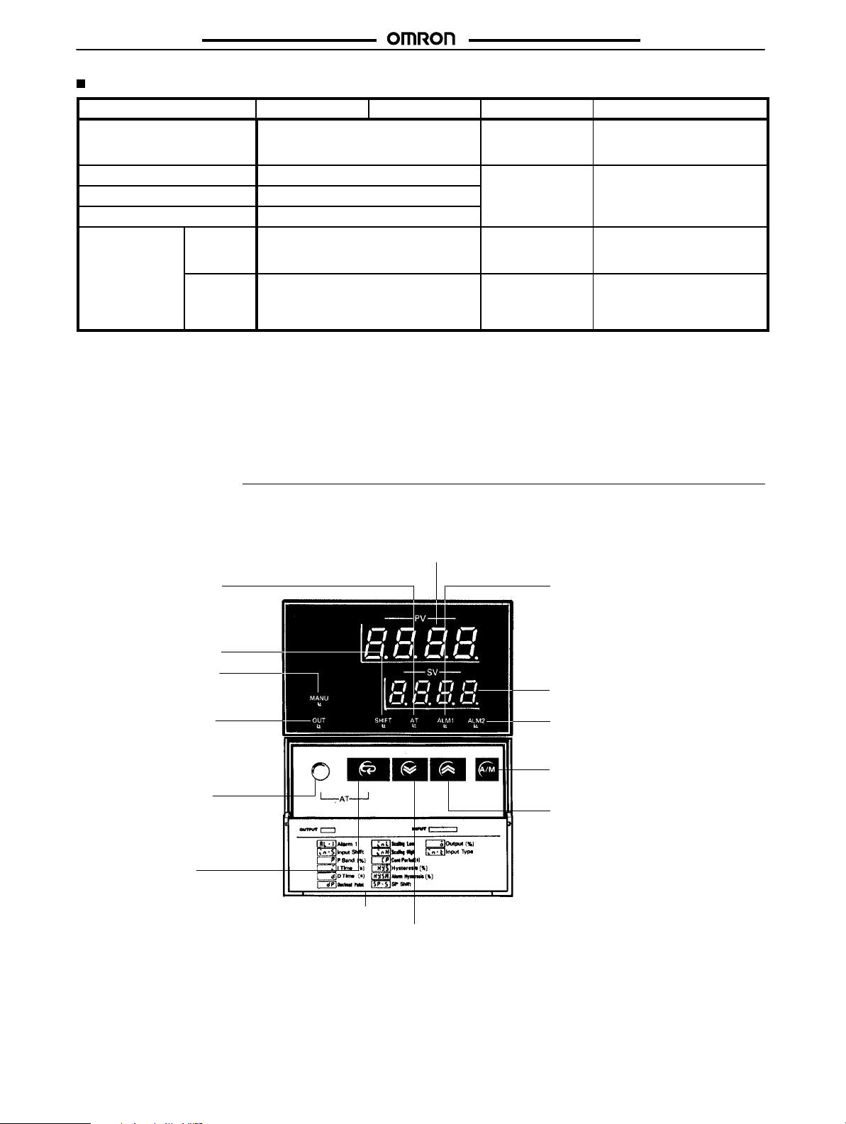
Nomenclature
Process Value (PV) Display
Displays not only the process value but also indicates the character for parameter being displayed on the SV display and error messages.
Auto-tuning Indicator
Flashes on and off every
second when auto-tuning is taking place.
Shift Set Indicator
Lights when shift set function is in operation.
Manual Mode Indicator
Lights when in manual
mode.
Output Indicator
Lights when the control
output is ON. Lights off
when the current output is
ON.
Level Key
Press for 2 seconds minimum to change levels to
set different groups of parameters.
Display Key
Press to shift the display
to the next parameter.
Front Cover
Down Key
Press to decrease the set value or other parameters. Successively decreases the value when held down.
Alarm 1 Indicator
Lights when the alarm 1 output is ON.
Set Value (SV) Display
Displays set value and other
parameters.
Alarm 2 Indicator
Lights when the alarm 2 output is ON.
A/M Key (Automatic/Manual)
Press for 1 second minimum to switch
between auto output mode and manual
output mode.
Up Key
Press to increase the set value or other parameters. Successively increases the value when held down.
4
Page 5
E5AX-LA/-MA
Operation
NOTICE: Always turn off power to the Digital Controller before changing any switch settings.
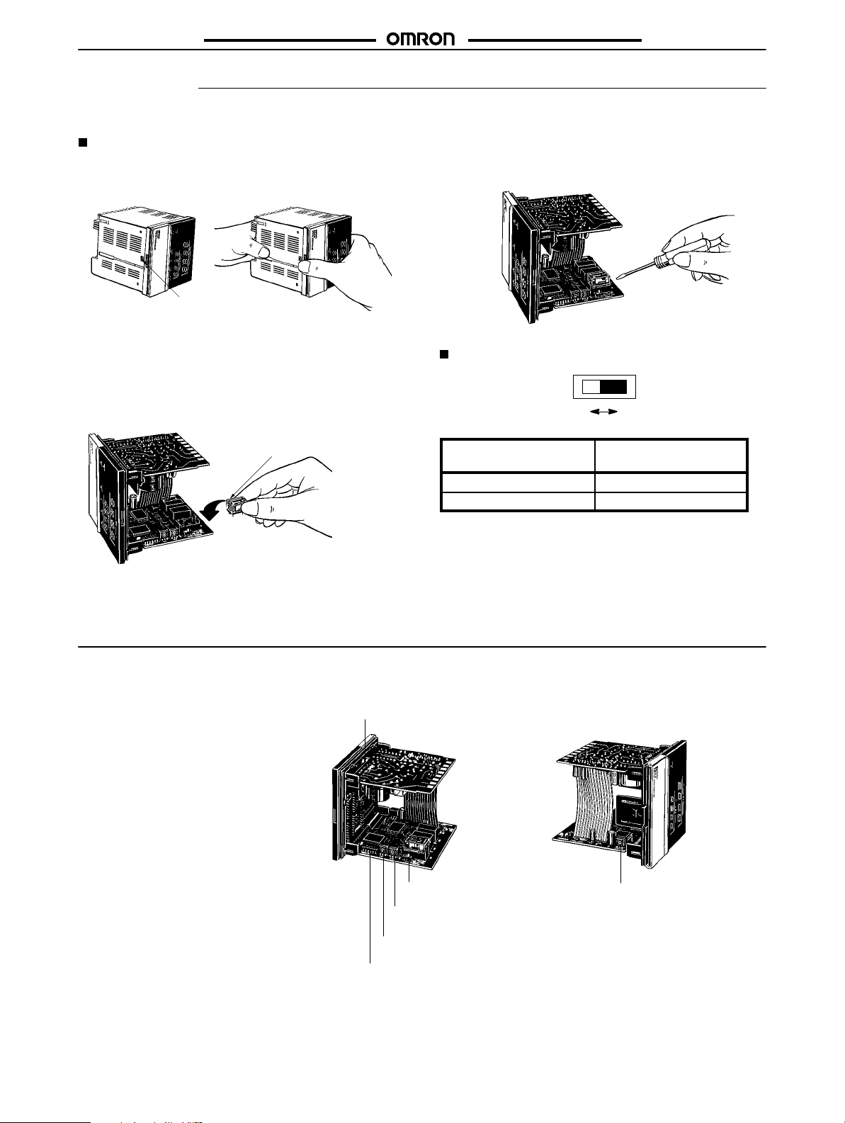
Settings
1. Remove the internal mechanism from the housing. Lift the
internal mechanism while pressing the hook at the bottom of
the front panel.
To remove a Control Output Unit, push it up with the tip of
a flat-blade screwdriver as shown below.
E5AX-LA/-MA
Hook
Pull out the internal mechanism
while holding down the hook with
your finger.
2. Connect a Control Output Unit to the vacant socket on the
printed circuit board as shown below.
Mount the Control Output Unit
with this mark facing the direction
indicated by the arrow.
Set the output selector to PUL (Pulse) when a Relay
(SW202, OUT), SSR, or Voltage Output Unit is mounted.
Set the output selector to CUR (current) when a Current
Output Unit is mounted.
3. Four internal switches must be set on the E5AX: the input
type selector, the operating mode selector, and the alarm
mode selectors 1 and 2.
Protection switch (SW101, PROTECT)
Flat-blade screwdriver
Output Selector (SW202)
OFF ON
PUL CUR
Output
Current ON
Pulse OFF
The figures show the locations of these switches and the
protection switches on the internal mechanisms. The
protection switch can be used to disable key operation.
Setting
(factory-set to OFF)
Output selector
(SW202, OUT)
Alarm mode selector 2
(SW203, ALM2)
Alarm mode selector 1
(SW205, ALM1)
Operating mode selector (SW 201,
FUNCTION)
Input type selector (SW206,
INPUT)
5
Page 6

E5AX-LA/-MA
E5AX-LA/-MA
Input Selector (SW206, INPUT)
This selector selects the input to be used. It is factory-set to position
0. The following table lists the other possible settings for input.
Switch setting E5AX-LA E5AX-MA
0 4 to 20 mA 0 to 100 mV
1 0 to 20 mA 0 to 10 mV
2 1 to 5 V –10 to 10 mV
3 0 to 5 V ---
4 0 to 1 V ---
5 --- ---
6 --- ---
7 --- ---
8 --- ---
9 --- ---
Note: Settings of 5 through 8 for LA models and settings of 3
through 8 for MA models are regarded the same as a setting of 0, i.e., 4 to 20 mA or 0 to 100 mV. A setting of 9 is
regarded the same as a setting of 1 for all models, i.e., 0 to
20 mA or 0 to 10 mV.
Operating Mode Selector (SW201,
FUNCTION)
This DIP switch selects the operational aspects listed in the following table.
Function
Control mode 1 ON ON/OFF operation
Control output 2 ON Normal
Input shift 3 ON Enabled
SP (set point)** 4 ON Enabled
protection cancel OFF Disabled
Not used.*** 5 Leave turned OFF.
PID display 6 ON Enabled
*PID with feed-forward circuitry.
**SP protection cancel is effective only when SW101 is ON. If the
SP protection cancel is ON, key protection (SW101 ON) will not apply to the set point, i.e., you will be able to change the set point regardless of the setting of SW101.
***Always operate with pin 5 OFF. Operating with pin 5 ON could result in malfunction.
Pin
number
Pin
setting
OFF PID operation*
OFF Reverse
OFF Disabled
OFF Disabled
Control setting
Alarm Mode Selectors (SW205: ALM1; SW203: ALM2)
Alarm mode selectors are provided for all E5AX Digital Controllers. Ten alarm modes, listed in the following table, can be selected using this
switch. The switch is factory-set to position 2, i.e., the upper-limit alarm mode.
6
Page 7

E5AX-LA/-MA
Switch Mode (SW203, 205) Alarm output Setting range
setting Alarm operation Display When X is positive When X is negative
0 No alarm No display OFF ---
1 Upper- and lower-limit alarm
)––(
XX
--- 0 to 9999
E5AX-LA/-MA
2 Upper-limit alarm
3 Lower-limit alarm
4 Upper- and lower-limit range
alarm
5 Upper- and lower-limit alarm with
standby sequence
6 Upper-limit alarm with standby
sequence
7 Lower-limit alarm with standby
sequence
8 Absolute-value alarm
9 SW205: Proportional alarm*
SW203: No alarm No display OFF
*The proportional alarm is detected when the temperature reaches
the set alarm point (A in the figure on the right), which is the lower
limit of a proportional band. When the temperature rises to the upper
limit of the proportional band (point B in the figure), the alarm output
is turned ON. This alarm function is convenient when the main setting is used for heating control, while the proportional alarm function
is used for cooling control, so that heating and cooling control can be
easily performed.
–––(
)–––
–()–
3––e
–––e
3–––
1––(
pro
X X
X X
XX
XX
X X
X X
Y
0
X X
---
---
Y
0
Note:
ON
X
AB
SP
PB: proportional band (fixed to 10.0% FS)
Proportional period is 20 seconds.
The operation of the alarm is not affected by pin
2 of the operating mode selector (SW201).
–999 to 9999
0 to 9999
–999 to 9999
PB
Key Protection Switch (SW101, PROTECT)
When the key protection switch is set to the ON position, the Level Key, Up and Down Keys, and Auto-tuning Key cannot be operated. In effect,
the Digital Controller is write-protected and the set values (such as the alarm value) can be read out only. The set point, however, will not be
protected if the SP protection disable is turned ON (pin 4 of SW201).
7
Page 8

E5AX-LA/-MA
E5AX-LA/-MA
Inputting Parameters
The Digital Controller has three display levels, 0, 1, and 2, in which only specific parameters can be set. Level 0 is the initial and is automatically
entered at power application. To change the mode to set or change a different group of parameters, hold down the Level Key for 2 seconds
minimum. The display level mode changes as shown below. Actual displays vary with models and switch settings. If a display does not appear
as expected, check your switch settings.
Level 0
PV
Power ON
Process value
SV
o 0
Process value
al–1
al–2
in–5
Level 0
Manual output value,
main setting, alarm set
value, input shift
Press a.
0.0
Press a.
0.0
Press a.
0.0
Press a.
0.0
Press a.
p
10.0
Press a.
i
240
Press a.
d
60
Press a.
–––––––
(Note 1)
Manual output setting
Main setting
(Note 2)
Alarm value 1
(Note 3)
Alarm value 2
(Note 4)
Input shift
(Note 5)
Proportional band
(Note 5)
Integral time
(Note 5)
Derivative time
Level 1 Level 2
Press the Level Key. Press the Level Key. Press the Level Key.
Decimal point setting, scaling
–––––––
setting, control period, hysteresis, hysteresis alarm setting,
shift set
Note: 1. Not displayed in auto output mode.
2. Not displayed when alarm 1 is disabled (SW205 set to
3. Not displayed when alarm 2 is disabled (SW203 set to 0
4. Not displayed when the input shift display is disabled
5. Not displayed when PID display is disabled (SW201, pin
Proportional Band: p
When the character p is displayed on the PV display, the proportional band (P constant) can be changed using the Up and Down
Keys. The new value will be displayed on the SV display. It can be
set in a range from 0.0 to 999.9% FS in units of 0.1% FS. The factory
setting is 10.0% FS.
Integral Time (Reset Time): i
When the character i is displayed on the PV display, the integral time
(I constant) can be changed using the Up and Down Keys. It can be
set in a range from 0 to 3,999 seconds in units of 1 second. The factory setting is 240 seconds.
Derivative Time (Rate Time): d
The derivative time (D constant) can be changed when the character d is displayed on the PV display using the Up and Down Keys. It
can be set in a range from 0 to 3,999 seconds in units of 1 second.
The factory setting is 60 seconds.
Process Value
Manual output value (only in manual output mode) and main setting
can be changed when process value is displayed by using the Up
and Down keys.
Selecting the Output Mode
The A/M Key can be pressed for one second or longer to change
between the auto and manual output modes.
Auto Output Mode
In auto output mode, the control will function automatically. When
the A/M Key is pressed and the auto output mode is first entered,
displays like the following will appear (display level 0).
Manual Output Mode
This mode is used to turn on outputs manually. Use the Up and
Down Keys to set the desired output value (as a percentage) in the
SV display. About 2 seconds after the desired value is set, outputs
will turn on accordingly.
Control output value, input type, alarm mode
0).
or 9).
(SW201, pin 3 ON).
6 ON).
PV
SV
–––––––
123
80
Process value
Main setting
8
Page 9

E5AX-LA/-MA
E5AX-LA/-MA
If the A/M Key is pressed to switch to the manual output mode, a display like the following will appear and the MANU indicator will light.
PV
SV
Balanceless-bumpless function prevents sudden changes in output
values when the mode is changed.
Note: 1. Balanceless-bumpless function will not operate in the
ON/OFF operating mode or when I is set to zero.
Alarm 1, 2 : al–1 , al–2
When al–1 or al–2 (or al) is displayed on the PV display, the alarm
value for alarm output can be set on the SV display. When the value
exceeds or falls below the set alarm value, the corresponding alarm
output is produced and the ALM indicator on the front panel lights.
Usually, the alarm value is set as a deviation from the set value, but it
can also be set as an absolute value when the event alarm mode is
selected. Set the alarm value by using the Up and Down Keys while
al is displayed. The message is not displayed if the alarm mode selector is set to position 0. Factory-set to upper-limit, alarm value 0.0.
Input Shift: in–5
Set the input value by using Up and Down Keys while in–5 is displayed.
Input shift value
0.0 (without shift) 10.0 10.0
1.0 (shifted by 1.0) 10.0 11.0
–1.0 (shifted by –1.0) 10.0 9.0
This function can be used mainly for fine tuning compensation,
while leaving the set value unaffected. Select this function by pressing the Display Key three times in display level 0, as shown below.
123
Process value
Set manual output
o 80
value (%)
Input value Display
Level 1
PV
SV
dp
Press a.
inl
0.0
Press a.
inh
100.0
Press a.
cp
20
Press a.
hys
0.2
Press a.
hysa
0.1
Press a.
sp–s
1
Decimal point setting
Scale value for 0% input
Scale value for 100% input
(Note 1)
Control period
(Note 2)
Hysteresis
(Note 3)
Hysteresis alarm
0.0
Shift set
Press a.
Note: 1. Not displayed in ON/OFF control (SW201 pin 1
If the input range is changed so that the main setting no longer lies
within it, the set point will automatically be changed to inl. If main setting stays within the range, the set point will remain as it is.
If inl is set to a value greater than or equal to inh, inl will automatically
be set to inh + 1.
If dp is set to 3, the leading zero will not be displayed for negative
values, e.g., –0.023 will be displayed as –.023.
Set inl and inh so that the difference between them (i.e., the resolution) is 5,000 or less. Otherwise, the display may not function properly.
ON) or current output (SW202 ON).
2. Not displayed in PID with feed-forward control circuit (SW201 pin 1 OFF). (However, if P is 0, the display will appear.)
3. Not displayed when the alarm 1 and 2 are disabled
(SW205 set to 0, and SW203 set to 0 or 9)
9
Page 10

E5AX-LA/-MA
E5AX-LA/-MA
Decimal Point: dp
Set the position of the decimal point by pressing the Up and Down
Keys. A value between 0 and 3 will be displayed to indicate the position of the decimal point as shown in the following table. The decimal
point is factory-set to 1.
Value of dp
0 1 0000
1 0.1 000.0
2 0.01 00.00
3 0.001 0.000
Scale Value for 0% Input: inl
Set the scale value for 0% input by pressing the Up and Down Keys.
The value can be set between –999 and 9998 in increments of 1 and
is factory-set to 0.0.
Scale Value for 100% Input: inh
Set the scale value for 100% input by pressing the Up and Down
Keys. The value can be set between –inl +1 and 9999 in increments
of 1 and is factory-set to 100.0.
Example:
When measuring liquid flow between 100.0 and 510.5 m
4 to 20 mA input.
1. The decimal point is set to “1.”
Decimal point
PV
SV
dp
a
3
/h using a
1
Hysteresis: hys
The hysteresis value for the ON/OFF control can be set between
0.0% and 100.0% FS while hy5 is displayed on the PV display using
the Up and Down Keys. The factory setting is 0.2% FS.
Hysteresis
Reverse operation
Normal operation
Hysteresis Alarm: hysa
The hysteresis alarm value for the alarm 1 and 2 can be set between
0.0% and 100.0% FS while hy5 is displayed on the PV display using
the Up and Down Keys. The factory setting is 0.1% FS.
Shift Set: sp–s
By short-circuiting the shift set input terminal, the control value is
shifted from the set value by the value input for the shift set. When
sp–s is displayed, the Up and Down Keys can be pressed to set the
shift set between –999 and 9999.
Set
value
200
150
ON
OFF
Low High
ON
OFF
Low
Shift set input
short-circuited
SP
Hysteresis
SP High
With a set value of
200 and a shift set
of –50
2. The 0% scale value is set to the value to be displayed for 4
mA, i.e.,100.0.
PV
SV
3. The 100% scale value is set to the value to be displayed for
20 mA, i.e.,510.5.
PV
SV
Control Period: cp
Control period for PID control with feed-forward can be set. To set
the control period, pin 1 on the operating mode selector (SW201)
must be set to the OFF position. When cp is displayed on the PV display, the control period can be set or changed in a range from 1 to 99
seconds in units of 1 second. The factory setting is 20 seconds.
When a Voltage Output Unit is used, it is recommended that the control period be set to 20 seconds or less (ideally, about 2 seconds), so
that the control operation can be performed more accurately.
Control output
ON
OFF
20 seconds
inl
100.0
a
inh
510.5
a
When control period is
set to 20 seconds
LED (SHIFT) is lit when a shift set input is short-circuited. sp–s is
factory-set to 0.
Level 2
In level 2 the control output value, selected input type, and modes
for alarm output can be monitored. Note that level 2 is a monitoring
level only and thus no parameters can be changed. When the Level
Key is pressed for 2 seconds minimum after power application, 5l–l
is displayed on the PV display. Hold down the Level Key again for 2
seconds minimum to display o on the PV display. Then the control
output value, selected input sensor, and alarm modes can be monitored each time the Display Key is pressed.
PV
SV
o
0
Control output value
Press a.
in–t
cur 1
Input sensor
Press a.
al–1
–––C
Alarm 1 mode
Press a.
al–2
–––C
Alarm 2 mode
Press a.
10
Page 11

E5AX-LA/-MA
E5AX-LA/-MA
Control Output Value: o
When the Digital Controller enters level 2, the control output value is
displayed on the SV display in a range of 0.0% to 100.0%.
Input Type: in–t
When in–t is displayed on the PV display, the present setting of the
input type selector (SW206), is displayed on the SV display. The following table shows the messages that may be displayed:
Model
E5AX-LA
E5AX-MA
Alarm Mode: al–1, al–2
When al is displayed on the PV display in level 2, alarm output mode
or the present setting of the corresponding alarm mode selector is
displayed on the SV display. The following table shows the messages that may be displayed.
Display Sensor
cur 1
cur 2
uol 1
uol 2
uol 3
uol 1
uol 2
uol 3
4 to 20 mA
0 to 20 mA
1 to 5 V
0 to 5 V
0 to 1 V
0 to 100 mV
0 to 10 mV
–10 to 10 mV
Display
No display No alarm
)––(
–––(
)–––
–()–
3––e
–––e
3–––
1––c
pro
Upper- and lower-limit alarm
Upper-limit alarm
Lower-limit alarm
Upper- and lower-limit range
alarm
Upper- and lower-limit alarms
with standby sequence
Upper-limit alarm with standby
sequence
Lower-limit alarm with standby
sequence
Absolute-value alarm
Proportional alarm
Alarm mode
Starting Control Operation
The E5AX will start control operations as soon as power is turned on
until power is turned off. If you don’t want control operations to be
performed while setting parameters, turn off the power and then turn
it back on after setting the desired parameters.
Auto-tuning
When the Level Key and Mode Key are pressed simultaneously for
1 second minimum, the Digital Controller automatically starts tuning
the PID constants. While auto-tuning is in operation, the auto-tuning
indicator on the front panel will flash. The Digital Controller executes
control based on the set PID constants (factory set to P = 10.0% FS,
I = 240 seconds, and D = 60 seconds) until process value of the controlled system reaches main setting. After that, the Digital Controller
automatically adjusts the PID constants using the limit cycle method. When the auto-tuning indicator turns off, the auto-tuning is terminated and PID constants are renewed.
Previous PID
Main
setting
Limit cycle method: The optimum PID constants are calculated by
this method by varying the control output variable and generating
external oscillation.
constants
AT indicator flashes
New PID constants
Auto-tuning can be carried out regardless of whether the Digital
Controller is performing reverse or normal operation. To stop autotuning, hold down the Level Key and Mode Key again simultaneously for 1 second minimum. All settings will return to those prior to the
beginning of auto-tuning. Automatic tuning can be executed at any
time: at power application, while the temperature is rising, or after
the control action has stabilized.
11
Page 12

E5AX-LA/-MA
E5AX-LA/-MA
Error Messages
The Digital Controller is provided with self-diagnostic functions, and will display an error message on the PV display when an error is detected.
Message
ffff
––––
5.err (flashes)
e111 (flashes)
e333 (flashes)
Note: If the display range (–999 to 9999) is exceeded, “FFFF” or “––––” will be displayed.
Input value has exceeded the upper-limit of
input range by 10% FS.
Input value has fallen below the lower-limit of
input range by 10% FS.
The input is disconnected or shorted or the
input value has greatly exceeded the input
range.
Memory failure (e111) or A/D converter failure
(e333) has occurred. Digital Controller must
be repaired if recovery is not made by turning
power off once and on again.
Cause Control output Alarm output
Pulse output Current output*
OFF during reverse operation
ON during normal operation
OFF during reverse operation
ON during normal operation
OFF Approx. 1 mA The output will turn ON ac-
OFF Approx. 1 mA OFF
4 mA during reverse operation
20 mA during normal operation
20 mA during reverse operation
4 mA during normal operation
Input Error Displays
The following displays will appear when the input is not within specifications for the various types of input.
The output will turn ON according to the alarm mode
for an input value that is
greater than the upper limit
of the input range by 10%
of full scale.
The output will turn ON according to the alarm mode
for an input value that is
less than the lower limit of
the input range by 10% of
full scale.
cording to the alarm mode
when the input goes to
maximum except in the
proportional alarm mode,
in which it will remain OFF.
Input
E5AX-LA 0 4 to 20 mA –––– –––– ffff (overflow) or 5.err
1 0 to 20 mA Value of cnl cnl –––– (underflow)
2 1 to 5 V –––– ––––
3 0 to 5 V Value of cnl cnl
4 0 to 1 V Value of cnl cnl
E5AX-MA 0 0 to 100 mV Value of 5.err cnl
1 0 to 10 mV Value of 5.err cnl
2 –10 to 10 mV Value of 5.err (cnh + cnl )/2
Example: If dp is 1, inl is 0.0, and inh is 100.0, the following displays will appear for burnouts or shorts.
Input
E5AX-LA 0 4 to 20 mA –––– ––––
1 0 to 20 mA 0.0 0.0
2 1 to 5 V –––– ––––
3 0 to 5 V 0.0 0.0
4 0 to 1 V 0.0 0.0
E5AX-MA 0 0 to 100 mV 5.err 0.0
1 0 to 10 mV 5.err 0.0
2 –10 to 10 mV 5.err 50.0
Burnout Short Outside input range Exceeding input
Burnout Short
12
Page 13

E5AX-LA/-MA
Dimensions
Note: All units are in millimeters unless otherwise indicated.
_96
E5AX-LA/-MA
12
89
11
2 to 11
Mounting
screw
Communications connector
(RS-232C and BCD connector is shown.)
RS-422 RS-485
RDB
RDA
SG
SDA
SDB
Communications board
(RS-422 and 485 terminals are shown.)
Panel Cutout Side-by-side Mounting
of N Controllers
+0.8
92
0
+0.8
+0.8
92
92
120 min.
0
0
L = (96N – 3.5)
4 to 20 mA
transmission output
SG
Communications board
(4 to 20 mA transmission output is shown.)
L
+1
0
13
Page 14

E5AX-LA/-MA
Installation
E5AX-LA/-MA
For relay
output
Control
output
Alarm output 1
Alarm output 2
Shift set input
For current
output
4 to 20 mA
For
SSR
output
For voltage
output
Precautions
Mounting
The dimensions of the Digital Controller conform to DIN 43700.
Recommended panel thickness is 1 to 8 mm.
Do not install the Digital Controller in a location exposed to excessive dust or corrosive gases. Moreover, avoid locations subject to
heavy vibration or shock, water or oil spray, or high temperatures.
Any of these condition will affect product life.
Isolate the Digital Controller from equipment that generates strong,
high-frequency noises such as high-frequency welders, because
such equipment may prevent proper operation.
Attach the two mounting brackets supplied with E5AX on the top
and bottom of the Digital Controller. Tighten the screws of the
mounting brackets with your fingers.
Mounting bracket
Ground FG terminal 18 under
noise-interfered environment
100 to 240 VAC, 50/60 Hz
E5AX-LA E5AX-MA
For 1 to 5 V,
0 to 5 V, 0 to 1 V
For 4 to 20 mA,
0 to 20 mA
For 0 to 100 mV
For 0 to 10 mV
–10 to 10 mV
Note: Do not connect unused terminals.
Solder-dipped Leads
Strip 6 to 12 mm of the lead wires and carefully arrange the wire tips.
Do not tighten the terminal screw with excessive force, because doing so may damage them. The terminal block of the Digital Controller is constructed so that the lead wires can be connected to all the
terminals from the same direction.
To p
Connection Examples
With Solderless Terminal
Use M3.5 solderless terminals with the Digital Controller’s M3.5
self-rising pressure plate screws.
14
Bottom
Input Connection
To reduce inductive noise influence, the lead wires connecting the
input to the Digital Controller must be separated from the power
lines and load lines.
Sequenced Circuits
Several seconds are required until the relay in turned ON after power has been supplied to the Digital Controller. Therefore, take this
time delay into consideration when designing sequenced circuits
which incorporate a Digital Controller.
Page 15

E5AX-LA/-MA
Terminal Arrangement Diagram on the Housing
The Digital Controller allows the input and output devices to be freely selected. Use the terminal arrangement diagram shown on the
housing of the Digital Controller to identify the output device
mounted on the Digital Controller, by marking the diagram as follows:
Check here with a felt-tip pen.
Output
100 to 240 VAC
3 A
Alarm 1
250 VAC
Stickers Inside Frontcover
Stickers indicating the input type and Control Output Unit (R, S, Q,
and C) are supplied with the Digital Controller. Attach the proper
stickers to the front panel as shown below, allowing the input type
and Control Output Unit mounted in the Digital Controller to be easily identified.
50/60 Hz 15 VA
E5AX-LA/-MA
Sticker identifying
Control Output Unit
Sticker identifying input type
ALL DIMENSIONS SHOWN ARE IN MILLIMETERS.
To convert millimeters into inches, multiply by 0.03937. To convert grams into ounces, multiply by 0.03527.
Cat. No. H52-E1-1A In the interest of product improvement, specifications are subject to change without notice.
OMRON Corporation
Temperature Control Devices Division
29th Fl., Crystal Tower Bldg.
1-2-27, Shiromi, Chuo-ku,
Osaka 540 Japan
Phone: 06-949-6070 Fax: 06-949-6084
Printed in Japan
0091-1M (0691)
15
 Loading...