

Page 1

E5AK
Digital Controller
Digital Controller (Programmable Type)
User's Manual
(Programmable Type)
Cat. No. H088-E1-01A
User's Manual
Cat. No. H088-E1-01A
Page 2

Preface
The E5AKĆT is a highĆperformance programmable digital controller. The E5AKĆT alĆ
lows the user to carry out the following:
• Set program patterns to each step by time or ramp rise rate
• Execute advance, hold and reset step operations
• Execute continuous operation of all patterns and repeated operation of same patterns
• Check the start of each step or program end time by signals.
• Count time from the beginning of each step (time signal)
• Select from many types of temperature and analog input (multiĆinput)
• Support positionĆproportional control (positionĆproportional type controllers only)
• Select output functions such as control output or alarm output (output assignment)
• Use the HBA (heater burnout alarm) function (standard type controllers only)
• Monitor the control loop by LBA (Loop Break Alarm)
• Use the communications function
• Calibrate input or transfer output
• The E5AKĆT also features a watertight construction (NEMA4: equivalent to IP66).
This User's Manual describes how to use the E5AKĆT.
Before using your E5AKĆT thoroughly read and understand this manual in order to
ensure correct use.
Also, store this manual in a safe place so that it can be retrieved whenever necessary.
PRECAUTIONS IN USING THE PRODUCT
When the product is used under the circumstances or environment below, ensure adĆ
herence to limitations of the ratings and functions. Also, take countermeasures for
safety precautions such as failĆsafe installations.
(1) Use under circumstances or environments which are not described in this user's manual.
(2) Use for nuclear power control, railway, air craft, vehicle, incinerator, medical equipment, enterĆ
tainment equipment, safety device, etc.
(3) Use for applications where death or serious property damage is possible and extensive safety preĆ
cautions are required.
About this manual
(1) All rights reserved. No part of this publication may be reproduced, stored in a retrieval system or transmitted,
in any form, or by any means, mechanical, electronic, photocopying, recording, or otherwise, without the prior
written permission of OMRON.
(2) Moreover, because OMRON is constantly striving to improve its high-quality products, the information in this
manual is subject to change without notice.
(3) Every precaution has been taken in the preparation of this manual. Nevertheless, if you find any errors or omis-
sions, please contact the branch of OMRON or sales office listed at the end of this manual, and inform them
of the catalog No. on the front cover.
I
Page 3
Conventions Used in This Manual
JMeanings of Abbreviations
Sometimes the following abbreviations are used in parameter names, figures and in text exĆ
planations. These abbreviations mean the following:
Symbol Term
PV Process value
SP (Present) set point *1
LBA Loop break alarm
HB Heater burnout
AT AutoĆtuning
EU Engineering unit *2
*1 In program pattern diagrams, the present SP is indicated.
*2 C, m, g and other units are indicated for scaled data. However, EU" is used as the minimum
unit for the data. For example, for 50.02 (m)", 1EU is taken as the minimum unit 0.01 (m).
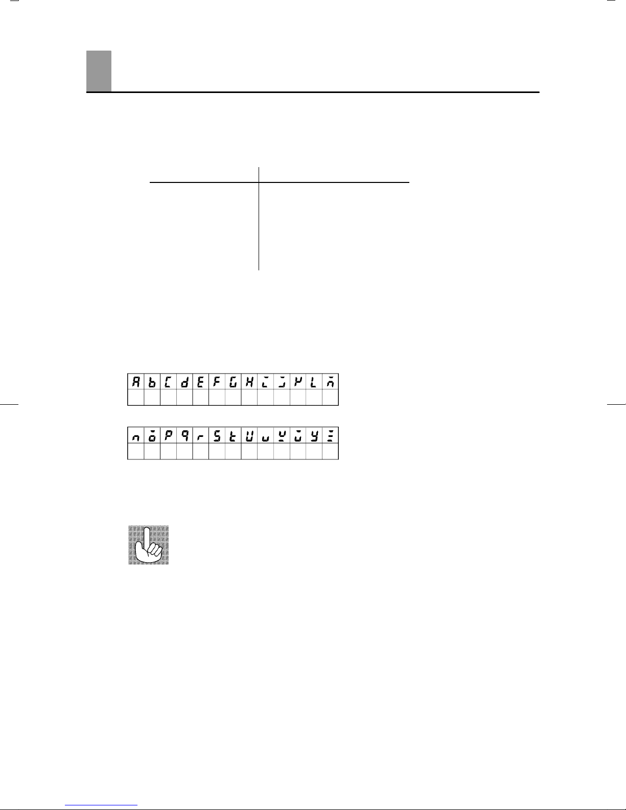
JHow to Read Display Symbols
The following tables show the correspondence between the symbols displayed on the displays
and alphabet characters.
ABCDEFGHI J KLM
NOPQRSTUVWXYZ
J“Reference” mark
This mark indicates that extra, useful information follows, such as supplementary explanations
and how to apply functions.
II
Page 4

JHow This Manual is Organized
Purpose Title Description
Learning about the gener-
al features of the E5AK-T
Chapteră1ăăINTRODUCĆ
TION
This chapter describes the feaĆ
tures of the E5AKĆT, names of
parts, and typical functions.
Setting up
Basic E5AK-T operations
Applied E5AK-T opera-
tions
Using a Position-propor-
tional type controller
Communications with a
host computer
Chapteră2ăăPREPARAĆ
TIONS
Chapteră3ăăBASIC OPERAĆ
TION
Chapteră5ăăPARAMETERS
Chapteră4ăăAPPLIED OPĆ
ERATION
Chapteră5ăăPARAMETERS
Chapteră4ăăAPPLIED OPĆ
ERATION
/4.1ăăSelecting the Control
Method
Chapteră6ăăUSING THE
COMMUNICATIONS
FUNCTION
This chapter describes the operaĆ
tions that you must carry out
(e.g. installation, wiring and
switch settings) before you can
use the E5AKĆT.
These chapters describe using
basic control examples how to
use the front panel keys and how
to view the display when setting
the parameters of the major funcĆ
tions for the E5AKĆT.
These chapters describes the imĆ
portant functions of the E5AKĆT
and how to use the parameters
for making full use of the
E5AKĆT.
This chapter describes how to use
the functions related specifically
to positionĆproportional type
controllers.
This chapter mainly describes
how to use the communications
commands, and gives program
examples.
Calibration
Troubleshooting
Chapteră7ăăCALIBRATION This chapter describes how the
user should calibrate the
E5AKĆT.
Chapteră8ăăTROUBLEĆ
SHOOTING
This chapter describes what to do
if any problems occur.
III
Page 5
PRECAUTIONS ON SAFETY
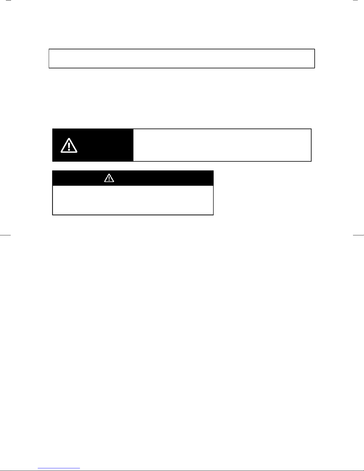
Marks For Ensuring Safe Use and Their Meanings
This manual uses the following marks to indicate precautions for ensuring that the
E5AKĆT is used safely.
The precautions indicated below describe important information regarding safety. Be
sure to follow the instructions described in these precautions.
WARNING
Incorrect handling may cause death or injury.
WARNING
Do not touch the terminals while the power is
ON.
This may cause an electric shock.
IV
Page 6

NOTICE
Be sure to observe these precautions to ensure safe use.
Do not use the product in places where explosive or flammable gases may be present.
Never disassemble, repair or modify the product.
Tighten the terminal screws properly.
Use the specified size of solderless terminals for wiring.
Use the product within the rated supply voltage.
Use the product within the rated load.
The life expectancy of the output relay varies considerably according to its switching capacity and
operating conditions. Be sure to use the output relay within its rated load and electrical life expecĆ
tancy. If the output relay is used beyond its life expectancy, its contacts may become fused or burned.
If you remove the controller from its case, never touch nor apply shock to the electronic parts inside.
Do not cover the E5AKĆT. (Ensure sufficient space around the controller to allow heat radiation.)
Do not use the controller in the following places:
Ă• Places subject to icing, condensation, dust, corrosive gas (especially sulfide gas or ammonia gas).
Ă• Places subject vibration and large shocks.
Ă• Places subject to splashing liquid or oil atmosphere.
Ă• Places subject to intense temperature changes.
Ă• Places subject to heat radiation from a furnace.
Be sure to wire properly with correct polarity of terminals.
When wiring input or output lines to your controller, keep the following points in mind to reduce the
influence from inductive noise:
Ă• Allow adequate space between the high voltage/current power lines and the input/output lines.
Ă• Avoid parallel or common wiring with high voltage sources and power lines carrying large currents.
Ă• Using separating pipes, ducts, and shielded line is also useful in protecting the controller, and its
lines from inductive noise.
Cleaning: Do not use paint thinner or organic solvents. Use standard grade alcohol to clean the prodĆ
uct.
Use a voltage (100 to 240 VAC at 50 to 60 Hz). At power ON, the prescribed voltage level must be
attained within two seconds.
Allow as much space as possible between the controller and devices that generate a powerful high
frequency (highĆfrequency welders, highĆfrequency sewing machines, etc.) or surge. These devices
may cause malfunctions.
If there is a large powerĆgenerating peripheral device and any of its lines near the controller, attach
a surge suppressor or noise filter to the device to stop the noise affecting the controller system. In
particular, motors, transformers, solenoids and magnetic coils have an inductance component, and
therefore can generate very strong noise.
When mounting a noise filter on the power supply to the controller, be sure to first check the filter's
voltage and current capacity, and then mount the filter as close as possible to the controller.
V
Page 7

Use within the following temperature and humidity ranges:
Ă• Temperature: Ć10C to 55C, humidity: 35%RH to 85%RH (with no icing or condensation)
If the controller is installed inside a control board, the ambient temperature must be kept to under
55C, including the temperature around the controller.
If the controller is subjected to heat radiation, use a fan to cool the surface of the controller to under
55C.
Store within the following temperature and humidity ranges:
Ă• Temperature: Ć25C to 65C, humidity: 35%RH to 85%RH (with no icing or condensation)
Never place heavy objects on, or apply pressure to the controller that may cause it to deform and deteĆ
riorate during use or storage.
Avoid using the controller in places near a radio, television set, or wireless installation. These devices
can cause radio disturbances which adversely affect the performance of the controller.
VI
Page 8

Table of Contents
Preface I. . . . . . . . . . . . . . . . . . . . . . . . . . . . . . . . . . . . . .
Conventions Used in This Manual II. . . . . . . . . . . . . . .
Precautions on Safety V. . . . . . . . . . . . . . . . . . . . . . . . .
CHAPTER 1 INTRODUCTION 1–1. . . . . . . . . . . . . . . . . . . . . . . . . . .
This chapter introduces the names of parts on the E5AK-T and their functions.
For details on how to use the controller and parameter settings, see Chapter 2
onwards.
1.1 Names of parts 1–2. . . . . . . . . . . . . . . . . . . . . . . . . . . . . . . . . . . . . . . . . .
1.2 Input and Output 1–5. . . . . . . . . . . . . . . . . . . . . . . . . . . . . . . . . . . . . . . . .
1.3 Program 1–8. . . . . . . . . . . . . . . . . . . . . . . . . . . . . . . . . . . . . . . . . . . . . . . .
1.4 Parameters and Menus 1–9. . . . . . . . . . . . . . . . . . . . . . . . . . . . . . . . . . .
1.5 About the Communications Function 1–12. . . . . . . . . . . . . . . . . . . . . . .
1.6 About Calibration 1–13. . . . . . . . . . . . . . . . . . . . . . . . . . . . . . . . . . . . . . . .
CHAPTER 2 PREPARATIONS 2–1. . . . . . . . . . . . . . . . . . . . . . . . . . .
This chapter describes the operations (e.g. setup, installation and wiring) you
should carry out before turning the E5AK-T ON.
2.1 Setup 2–2. . . . . . . . . . . . . . . . . . . . . . . . . . . . . . . . . . . . . . . . . . . . . . . . . .
2.2 Installation 2–5. . . . . . . . . . . . . . . . . . . . . . . . . . . . . . . . . . . . . . . . . . . . . .
2.3 Wiring Terminals 2–8. . . . . . . . . . . . . . . . . . . . . . . . . . . . . . . . . . . . . . . . .
CHAPTER 3 BASIC OPERATION 3–1. . . . . . . . . . . . . . . . . . . . . . . .
This chapter describes actual examples for understanding the basic operation of
the E5AK-T.
3.1 Convention Used in this Chapter 3–2. . . . . . . . . . . . . . . . . . . . . . . . . . .
3.2 Setting Input Specifications 3–4. . . . . . . . . . . . . . . . . . . . . . . . . . . . . . .
3.3 Setting Output Specifications 3–7. . . . . . . . . . . . . . . . . . . . . . . . . . . . . .
3.4 Setting Alarm Type 3–10. . . . . . . . . . . . . . . . . . . . . . . . . . . . . . . . . . . . . . .
3.5 Setting Patterns 3–14. . . . . . . . . . . . . . . . . . . . . . . . . . . . . . . . . . . . . . . . .
3.6 Protect Mode 3–19. . . . . . . . . . . . . . . . . . . . . . . . . . . . . . . . . . . . . . . . . . . .
3.7 Starting and Stopping Operation 3–21. . . . . . . . . . . . . . . . . . . . . . . . . . .
3.8 Adjusting Control Operation 3–22. . . . . . . . . . . . . . . . . . . . . . . . . . . . . . .
CHAPTER 4 APPLIED OPERATION 4–1. . . . . . . . . . . . . . . . . . . . . .
This chapter describes each of the parameters required for making full use of the
features of the E5AK-T.
Read this chapter while referring to the parameter descriptions in chapter 5.
4.1 Selecting the Control Method 4–2. . . . . . . . . . . . . . . . . . . . . . . . . . . . . .
4.2 Operating Condition Restrictions 4–7. . . . . . . . . . . . . . . . . . . . . . . . . . .
4.3 Ramp Rise Rate Setup Program 4–9. . . . . . . . . . . . . . . . . . . . . . . . . . .
4.4 Program Operation 4–13. . . . . . . . . . . . . . . . . . . . . . . . . . . . . . . . . . . . . .
Page 9

4.5 Wait Operation 4–16. . . . . . . . . . . . . . . . . . . . . . . . . . . . . . . . . . . . . . . . . .
4.6 Program output 4–17. . . . . . . . . . . . . . . . . . . . . . . . . . . . . . . . . . . . . . . . . .
4.7 Setting Running Conditions 4–19. . . . . . . . . . . . . . . . . . . . . . . . . . . . . . .
4.8 How to Use Event Input 4–21. . . . . . . . . . . . . . . . . . . . . . . . . . . . . . . . . .
4.9 How to Use the Heater Burnout Alarm 4–23. . . . . . . . . . . . . . . . . . . . . .
4.10 LBA 4–26. . . . . . . . . . . . . . . . . . . . . . . . . . . . . . . . . . . . . . . . . . . . . . . . . . . .
4.11 How to Use Transfer Output 4–28. . . . . . . . . . . . . . . . . . . . . . . . . . . . . . .
CHAPTER 5 PARAMETERS 5–1. . . . . . . . . . . . . . . . . . . . . . . . . . . . .
This chapter describes the parameters of the E5AK-T.
Use this chapter as a reference guide.
Conventions Used in this Chapter 5–2. . . . . . . . . . . . . . . . . . . . . . . . . . . . . .
Protect Mode 5–3. . . . . . . . . . . . . . . . . . . . . . . . . . . . . . . . . . . . . . . . . . . . . . . .
Manual Mode 5–5. . . . . . . . . . . . . . . . . . . . . . . . . . . . . . . . . . . . . . . . . . . . . . . .
Level 0 Mode 5–6. . . . . . . . . . . . . . . . . . . . . . . . . . . . . . . . . . . . . . . . . . . . . . . .
Program Mode 5–11. . . . . . . . . . . . . . . . . . . . . . . . . . . . . . . . . . . . . . . . . . . . . . .
Level 1 Mode 5–17. . . . . . . . . . . . . . . . . . . . . . . . . . . . . . . . . . . . . . . . . . . . . . . .
Level 2 Mode 5–24. . . . . . . . . . . . . . . . . . . . . . . . . . . . . . . . . . . . . . . . . . . . . . . .
Setup Mode 5–30. . . . . . . . . . . . . . . . . . . . . . . . . . . . . . . . . . . . . . . . . . . . . . . . .
Expansion Mode 5–38. . . . . . . . . . . . . . . . . . . . . . . . . . . . . . . . . . . . . . . . . . . . .
Option Mode 5–46. . . . . . . . . . . . . . . . . . . . . . . . . . . . . . . . . . . . . . . . . . . . . . . . .
Calibration Mode 5–52. . . . . . . . . . . . . . . . . . . . . . . . . . . . . . . . . . . . . . . . . . . . .
CHAPTER 6 USING THE COMMUNICATIONS FUNCTION 6–1. .
This chapter mainly describes communications with a host computer and communications commands.
6.1 Outline of the Communications Function 6–2. . . . . . . . . . . . . . . . . . . .
6.2 Preparing for Communications 6–3. . . . . . . . . . . . . . . . . . . . . . . . . . . .
6.3 Command Structure 6–5. . . . . . . . . . . . . . . . . . . . . . . . . . . . . . . . . . . . . .
6.4 Commands and Responses 6–7. . . . . . . . . . . . . . . . . . . . . . . . . . . . . . .
6.5 How to Read Communications Error Information 6–15. . . . . . . . . . . . .
6.6 Program Example 6–17. . . . . . . . . . . . . . . . . . . . . . . . . . . . . . . . . . . . . . .
CHAPTER 7 CALIBRATION 7–1. . . . . . . . . . . . . . . . . . . . . . . . . . . . .
This chapter describes procedures for each calibration operation.
Read this chapter only when the controller must be calibrated.
7.1 Parameter Structure 7–2. . . . . . . . . . . . . . . . . . . . . . . . . . . . . . . . . . . . .
7.2 Calibrating Thermocouples 7–4. . . . . . . . . . . . . . . . . . . . . . . . . . . . . . . .
7.3 Calibrating Platinum Resistance Thermometers 7–7. . . . . . . . . . . . .
7.4 Calibrating Current Input 7–9. . . . . . . . . . . . . . . . . . . . . . . . . . . . . . . . . .
7.5 Calibrating Voltage Input 7–10. . . . . . . . . . . . . . . . . . . . . . . . . . . . . . . . . .
Page 10

7.6 Checking Indication Accuracy 7–12. . . . . . . . . . . . . . . . . . . . . . . . . . . . .
CHAPTER 8 TROUBLESHOOTING 8–1. . . . . . . . . . . . . . . . . . . . . .
This chapter describes how to find out and remedy the cause if the E5AK-T does
not function properly .
Remedy E5AK-T trouble in the order of the descriptions in this chapter
8.1 Initial Checks 8–2. . . . . . . . . . . . . . . . . . . . . . . . . . . . . . . . . . . . . . . . . . . .
8.2 How to Use the Error Display 8–3. . . . . . . . . . . . . . . . . . . . . . . . . . . . . .
8.3 How to Use the Error Output 8–5. . . . . . . . . . . . . . . . . . . . . . . . . . . . . .
8.4 Checking Operation Restrictions 8–6. . . . . . . . . . . . . . . . . . . . . . . . . . .
APPENDIX
SPECIFICATIONS A–2. . . . . . . . . . . . . . . . . . . . . . . .
ABOUT CURRENT TRANSFORMER (CT) A–5. . .
CONTROL BLOCK DIAGRAM A–6. . . . . . . . . . . . . .
SETTING LIST A–8. . . . . . . . . . . . . . . . . . . . . . . . . . .
MODEL LIST A–12. . . . . . . . . . . . . . . . . . . . . . . . . . . . .
PARAMETER OPERATIONS LIST A–13. . . . . . . . . .
ASCII CODE LIST A–15. . . . . . . . . . . . . . . . . . . . . . . .
INDEX
REVISION HISTORY
Page 11

CHAPTER1
CHAPTER 1
INTRODUCTION
This chapter introduces the names of parts on the E5AKĆT and their
functions.
For details on how to use the controller and parameter settings, see
Chapter 2 onwards.
CHAPTER 1 INTRODUCTION
1.1 Names of parts 1Ć2. . . . . . . . . . . . . . . . . . . . . . . .
Main parts 1Ć2. . . . . . . . . . . . . . . . . . . . . . . . . . . .
Front panel 1Ć2. . . . . . . . . . . . . . . . . . . . . . . . . . .
About the displays 1Ć3. . . . . . . . . . . . . . . . . . . . .
How to use keys 1Ć4. . . . . . . . . . . . . . . . . . . . . . .
1.2 Input and Output 1Ć5. . . . . . . . . . . . . . . . . . . . . .
Input 1Ć5. . . . . . . . . . . . . . . . . . . . . . . . . . . . . . . . .
Output 1Ć6. . . . . . . . . . . . . . . . . . . . . . . . . . . . . . . .
1.3 Program 1Ć8. . . . . . . . . . . . . . . . . . . . . . . . . . . . . .
How programs are structured 1Ć8. . . . . . . . . . .
Program operation 1Ć8. . . . . . . . . . . . . . . . . . . . .
Alarm output 1Ć8. . . . . . . . . . . . . . . . . . . . . . . . . .
Program output 1Ć8. . . . . . . . . . . . . . . . . . . . . . . .
1.4 Parameters and Menus 1Ć9. . . . . . . . . . . . . . . . .
Parameter types 1Ć9. . . . . . . . . . . . . . . . . . . . . . .
Selecting modes 1Ć10. . . . . . . . . . . . . . . . . . . . . . . .
Selecting parameters 1Ć11. . . . . . . . . . . . . . . . . . .
Fixing settings 1Ć11. . . . . . . . . . . . . . . . . . . . . . . . .
1.5 About the Communications Function 1Ć12. . . .
1.6 About Calibration 1Ć13. . . . . . . . . . . . . . . . . . . . . .
1–1
Page 12
CHAPTER 1 INTRODUCTION
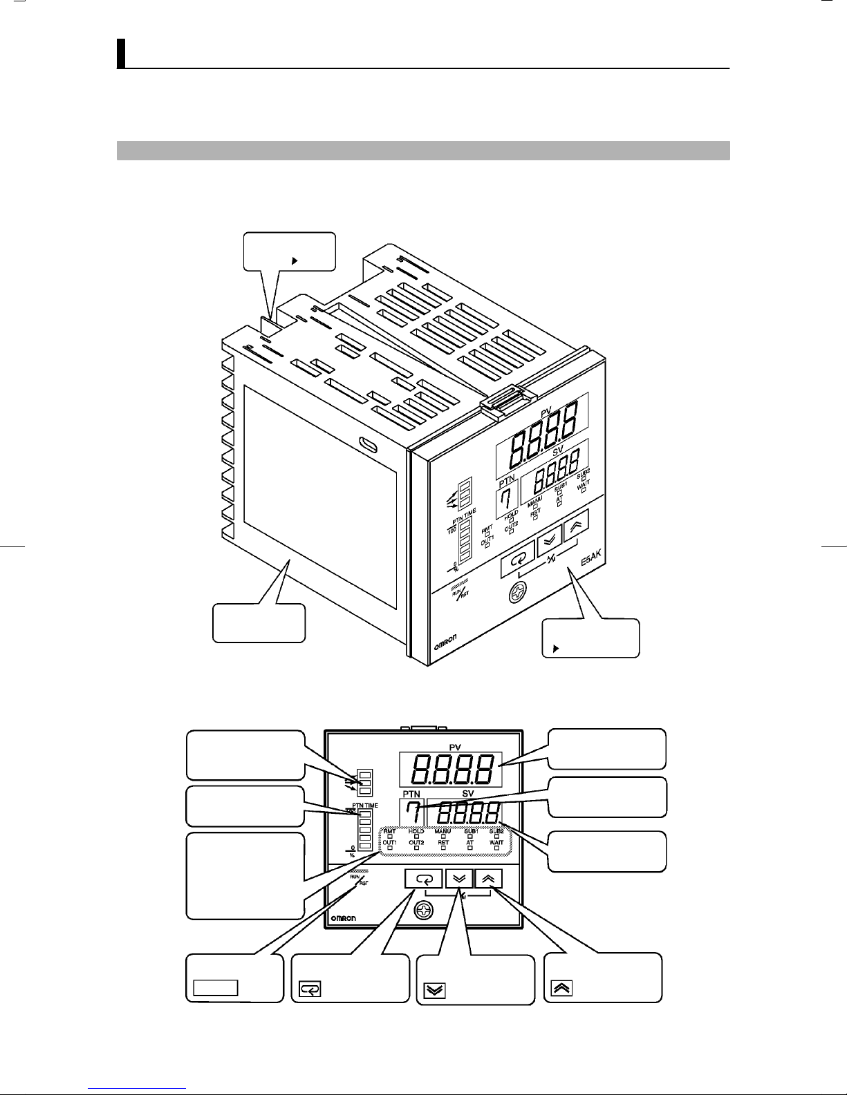
1.1 Names of parts
JMain parts
Terminals
P 2-6
Rear case
JFront panel
Program state indicators
Bar graph
Operation st atus indicators
OUT1
SUB1
MANU
HOLD
WAIT
Run/Reset key Display key Down key Up key
RUN/RST
OUT2
SUB2
RMT
RST
AT
Front panel
This page
No.1 display
Pattern No.
No.2 display
E5AK
1–2
Page 13

JAbout the displays
1.1 Names of parts
F No.1 display
F No.2 display
F Pattern No.
F Program status
indicators
F Operation status
indicators
Displays the process value or parameter symbols.
Displays the set point, manipulated variable or parameter settings.
Displays pattern No..
Indicate how the presentĆSP of the operating step changes.
Ă• OUT1
Lights when the pulse output function assigned to control output 1" is
ON.
Ă• OUT2
Lights when the pulse output function assigned to control output 2" is
ON.
Ă• SUB1
Lights when the pulse output function assigned to auxiliary output 1"
is ON.
Ă• SUB2
Lights when the pulse output function assigned to auxiliary output 2"
is ON.
Ă• MANU
Lights in the manual operation mode.
Ă• RST
Lights when the control is in reset status.
Ă• RMT
Lights during remote operation.
Ă• HOLD
Lights when the program is in hold status.
Ă• WAIT
Lights when the program is in wait status.
Ă• AT
Flashes during autoĆtuning.
F Bar graph
Ă• This bar graph indicates how much of the pattern has elapsed in 20% inĆ
crements (five stages) per single segment.
1–3
Page 14

CHAPTER 1 INTRODUCTION
JHow to use keys
RUN/RST
F key
F key
F key
The following describes basic key operations.
To change to run operation from the reset status, press this key for one seĆ
cond minimum.
To change to the reset status from run operation, press this key for two seĆ
conds minimum.
The functions of this key change according to how long it is pressed. If the
key is pressed for less than one second, the parameters are switched. If the
key is pressed for one second minimum, the menu display appears. In key
operations from here on, press the key" refers to pressing the key for less
than one second.
For details on switching of parameters and menu display items, see page
1Ć10.
Each press of key increments or advances the values or settings on the
No.2 display, while each press of the key decrements or returns the
values or settings on the No.2 display.
Functions vary, for example, when the
RUN/RST
key is held down simultaĆ
neously with the key, or a key is held down continuously. For details,
see page 1Ć10. Also, chapters 3 and 4 describe examples using various key
combinations.
1–4
Page 15
1.2 Input and Output
1.2 Input and Output
Temperature input
Voltage input
Current input
CT input
Potentiometer
Event input
Controller
Control output
(heat)
Control output
(cool)
Alarm 1
Alarm 2
Alarm 3
HBA
LBA
Time signal 1
Time signal 2
Program end
Stage output
Error 1
Error 2
Control output 1
Control output 2
Auxiliary output 1
Auxiliary output 2
Transfer output
JInput
The E5AKĆT supports the following inputs:
Temperature input, Current input, Voltage input, CT input/potentiomeĆ
ter, and Event input.
F Temperature input/Voltage input/Current input
Ă• Only one of temperature input, current input and voltage input can be
selected and connected to the controller.
Ă• The following input sensors can be connected for temperature input:
Thermocouple: K, J, T, E, L, U, N, R, S, B, W, PLII
Platinum resistance thermometer: JPt100, Pt100
Ă• The following currents can be connected for current input:
4 to 20 mA, 0 to 20 mA
Ă• The following voltages can be connected for voltage input:
1 to 5 VDC, 0 to 5 VDC, 0 to 10 VDC
F CT input/Poten-
tiometer
Ă• Connect CT input when using the HBA (heater burnout alarm) function
on a standard type controller (E5AKĆTAA2). Note that CT input cannot
be used when the linear output unit is mounted.
Ă• Connect the potentiometer when monitoring the valve opening on a
positionĆproportional type controller (E5AKĆTPRR2).
1–5
Page 16

CHAPTER 1 INTRODUCTION
F Event input
JOutput
F Output assign-
ments
Add on the input unit (E53ĆCKB) when using event input. You can select
from the following six event inputs:
Run/Reset, Remote/Local, Auto/Manual, Hold/Hold Cancel, Advance,
Pattern
The output functions of the E5AKĆT do not operate for five seconds after the
E5AKĆT is turned ON.
The E5AKĆT supports the following five outputs:
Control output 1
Control output 2
Auxiliary output 1
Auxiliary output 2
Transfer output
When using control output 1 and 2, set the output unit (sold separately).
Nine output units are available to suit the output circuit configration.
When using transfer output, add on the communication unit (E53ĆAKF).
Ă• The E5AKĆT supports the following thirteen output functions:
Control output (heat), Control output (cool), Alarms 1 to 3, HBA,
LBA, Time Signals 1 and 2, Program End, Stage Output,
Error 1 (input error), Error 2 (A/D converter error)
Ă• Assign these output functions to control output 1, control output 2, auxĆ
iliary output 1, and auxiliary output 2.
However, note that as control output 1 is used as the open output and
control output 2 is used as close output on a positionĆproportional type
controller (E5AKĆTPRR2), control outputs 1 and 2 cannot be used as asĆ
signment destinations. Also, of the output functions, control output
(heat), control output (cool), HBA and LBA are disabled.
Ă• On a standard type controller, there are restrictions on how assignment
destinations (control output 1, control output 2, auxiliary output 1, and
auxiliary output 2) can be used. For details, see Chapter 3 Basic OperaĆ
tion/3.3 Setting Output Specifications (page 3Ć7).
Ă• In the example on the previous page, control output (heat)" is assigned
to control output 1", alarm 1" is assigned to control output 2", and
alarm 2" is assigned to auxiliary output 1". Accordingly, the configuĆ
ration is such that heating control output is connected to control output
1, and alarm output is connected to control output 2 and auxiliary outĆ
put 1.
Ă• Control outputs 1 and 2 are used depending on the differences in control
method as follows:
1–6
Page 17

1.2 Input and Output
F Transfer output
Control Method Model
Standard control E5AK-TAA2 AC100-240
E5AK-TAA2 AC/DC24
Heating and
cooling control
Position-proportional control
Ă• The E5AKĆT supports the following five transfer outputs:
Set point, Process value, Heating side manipulated variable,
Cooling side manipulated variable, Valve opening
However, note that heating/cooling side manipulated variables can be outĆ
put only on standard type controllers, and valve opening can be output
only on positionĆproportional type controllers.
Ă• These transfer outputs can be output after being scaled. Setting of an upĆ
per limit value smaller than the lower limit value is allowed, so reverse
scaling can also be carried out.
E5AK-TAA2 AC100-240
E5AK-TAA2 AC/DC24
E5AK-TPRR2 AC100-240
E5AK-TPRR2 AC/DC24
Control Output 1/
Control Output 2
Control output (heat)
/ Alarm, etc.
Control output (heat)
/ Control output (cool)
Open/Close
1–7
Page 18

CHAPTER 1 INTRODUCTION
1.3 Program
JHow programs
are structured
E5AKĆT allows you to configure programs made up of a maximum of eight
patterns (pattern 0 to 7).
The number of steps (16 maximum) in each pattern can be specified in paĆ
rameters.
Pattern 7
Pattern 1
Pattern 0
Step 0 Step 1 Step 2 Step 15
Ă• Generally, the time setup method" is used to configure programs. By
this method, set points at each step and time are used as program eleĆ
ments. However, the ramp rise rate setup method" can also be used. By
this method, the set point, ramp time and soak times are used as program
elements.
JProgram opera-
tion
F Step operation
F Wait operation
JAlarm output
JProgram output
1–8
Ă• Generally, the target patterns are specified before the program is
executed.
Ă• In parameter setup, you can specify repeated execution of the same patĆ
tern (Repeat) or consecutive execution of all patterns 0 to 7 (Run all).
Ă• During program operation, steps can be skipped (Advance) and the conĆ
trol monitoring can be paused (Hold).
Ă• When the wait width is specified in parameter setup, the program does
not go to the next step and waits until the PV reaches the specified time
(wait width) at the end of each step.
Ă• Alarms that are assigned as outputs operate referenced to the alarm valĆ
ues preset to each pattern.
Ă• Time signals, program end and stage output can be output according to
output assignment.
Ă• ON/OFF signals are output as time signals according to the timer that
takes a specified step as its start point.
Page 19

1.4 Parameters and Menus
1.4 Parameters and Menus
JParameter types
F Protect mode
F Manual mode
E5AKĆT parameters are distributed between the following ten modes:
Protect mode
Manual mode
Level 0 mode
Program mode
Level 1 mode
Level 2 mode
Setup mode
Expansion mode
Option mode
Calibration mode
The settings of parameters in each of eight modes (excluding the protect
mode and manual mode) can be checked and modified by selection on the
menu display.
The protect function is for preventing unwanted modification of parameĆ
ters, and switching between run and reset operation or auto and manual
operation.
In this mode, the controller can be switched to manual operation. The maĆ
nipulated variable can be manipulated manually only in this mode.
F Level 0 mode
F Program mode
F Level 1 mode
F Level 2 mode
F Setup mode
Set the controller to this mode during normal operation. In this mode, you
can change the set point and pattern during operation, and execute step
operation (e.g. advance). You can only monitor (not change) the process
value, step No., standby time, pattern elapsing time, pattern execution
count and manipulated variable.
This is the programming mode. In this mode, you can set the number of
steps used in each pattern, pattern execution count, alarm values, set
points for each step, step time, and time signals for two steps.
This is the main mode for adjusting control. In this mode, you can execute
AT (autoĆtuning), and set up the control period, PID parameters and heatĆ
er burnout alarm (HBA) conditions.
This is the auxiliary mode for adjusting control. In this mode, you can set
the parameters for limiting the manipulated variable, switch between the
remote and local modes, and set the loop break alarm (LBA), alarm hysterĆ
esis and the digital filter value of inputs.
This is the mode for setting the basic specifications. In this mode, you can
set parameters that must be checked or set before operation such as the
input type, scaling, output assignments and direct/reverse operation.
1–9
Page 20
CHAPTER 1 INTRODUCTION
F Expansion mode
F Option mode
F Calibration mode
JSelecting modes
This is the mode for setting expanded functions. In this mode, you can set
SP setting limitter, switching between advanced PID control or ON/OFF
control, program time unit, selection of step time/rate of rise programĆ
ming, time unit of ramp rise rate, and the time for automatic return to the
monitoring display.
This is the mode for setting optional functions. You can select this mode
only when an option unit is mounted in the controller. In this mode, you
can set the communications conditions, transfer output and event input
parameters to match the type of option unit mount in the controller. HeatĆ
er burnout alarm function and positionĆproportional travel time are also
located in this mode.
This mode is provided so that the user can calibrate inputs and output.
When calibrating input, the selected input type is calibrated. Whereas,
transfer output can be calibrated only when the communication unit
(E53ĆAKF) is set in the controller.
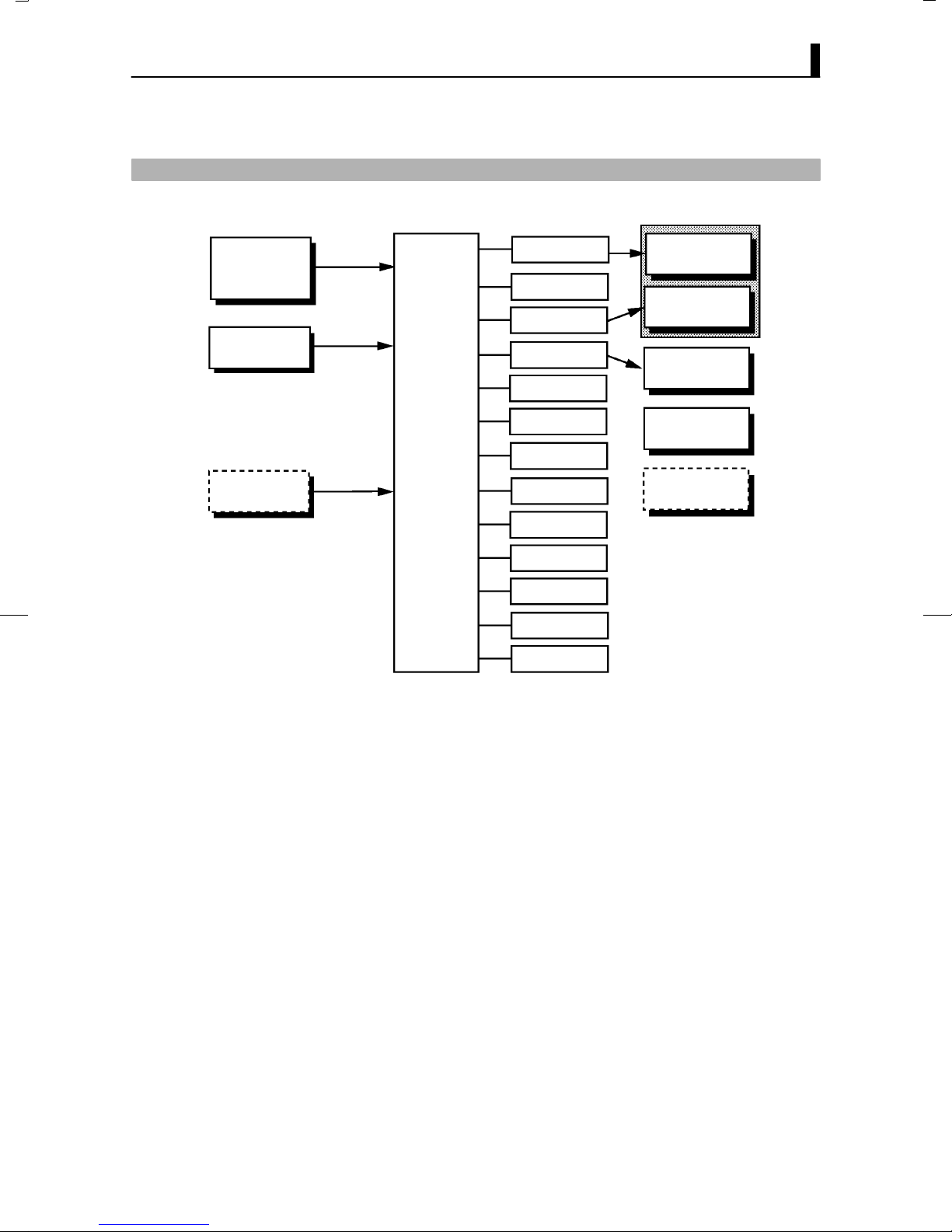
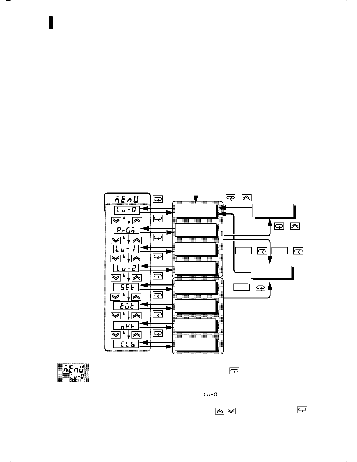
The following diagram shows the order in which modes are selected.
Power ON
+
1 second min.
Level 0 mode
1 second min.
Manual mode
1 second min.
1 second min.
1 second min.
1 second min.
1 second min.
1 second min.
1 second min.
Program mode
Level 1 mode
Level 2 mode
Setup mode
Expansion mode
Option mode
Calibration mode
RUN/RST
1 second min.
RUN/RST
1 second min.
+
Protect mode
+
+
1 second min.
RUN/RST
1 second min.
+
Ă• To select the menu display in any of the above modes (excluding the proĆ
tect mode and manual mode), press the key for 1 second minimum.
When you have selected the menu display, the previous mode is selected.
For example, if you selected the menu display while in the level 0 mode,
the No.2 display changes to [ ] as shown on the left.
Ă• To move to the desired mode after you have entered the menu display,
select the desired mode using the keys and hold down the
key for one second minimum. The display switches to the first parameter
of the mode that you specified.
1–10
Page 21
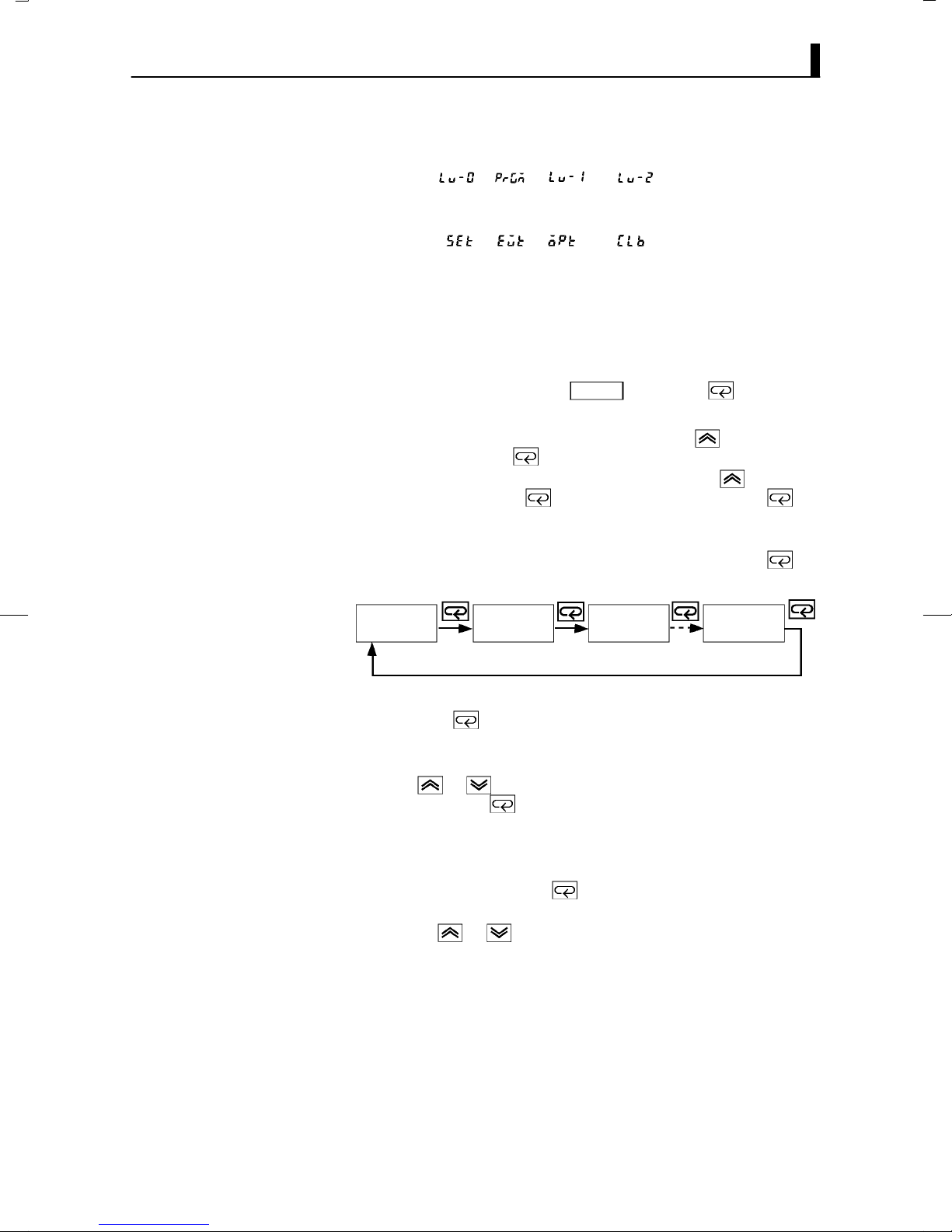
1.4 Parameters and Menus
Ă• Protected modes cannot be selected. Also, the menu display does not apĆ
pear when modes are protected up to the program mode.
Ă• If you select [ ], [ ], [ ] or [ ] in the menu display, the
level 0, program, level 1 and level 2 modes, respectively, are selected.
These modes are selected with control still continuing.
Ă• If you select[ĂĂ ] [ĂĂ ] [ĂĂ ] or [ĂĂ ] in the menu display, the
setup, expansion, option and calibration modes, respectively, are seĆ
lected.
When these modes are selected, the control is reset. So, control outputs
and auxiliary output are turned OFF. When another mode is selected
while in these modes control, reset is canceled.
Ă• To set the controller to the protect mode or to return to the level 0 mode
from the protect mode, press the
neously for 1 second minimum.
Ă• To set the controller to the manual mode, press the key for one seĆ
cond minimum with the key held down in the level 0 to 2 modes. To
return to the level 0 mode in the manual mode, press the key for one
second minimum with the key pressed. Be sure to press the key
first in this operation.
RUN/RST
key and the key simultaĆ
JSelecting
parameters
JFixing settings
Ă• When the controller is not in the manual mode, each press of the key
switches the parameter in the respective mode.
Parameter
1
Ă• If you press the key when at the final parameter, the display returns
to the top parameter for the current mode.
Ă• When you change parameter settings or contents, specify the parameter
using the or keys, and either leave the setting for at least two
seconds or press the key. This fixes the setting.
Ă• When another mode is selected, the content of the parameters before the
mode was selected is fixed.
Ă• When you turn the power OFF, you must first fix the settings and paramĆ
eter contents (by pressing the key or selecting another mode). The
settings and parameter contents are sometimes not changed by merely
pressing the or keys.
Parameter
2
Parameter
3
Parameter
n
1–11
Page 22

CHAPTER 1 INTRODUCTION
1.5 About the Communications Function
The E5AKĆT can be provided with a communications function that allows
you to check and set controller parameters from a host computer. If the
communications function is required, add on the communications unit.
For details on the communications function, refer to Chapter 6.
F RS-232C
F RS-422
F RS-485
When using the communications function on the RSĆ232C interface, add
on the communications unit (E53ĆAK01).
When using the communications function on the RSĆ422 interface, add on
the communications unit (E53ĆAK02).
When using the communications function on the RSĆ485 interface, add on
the communications unit (E53ĆAK03).
1–12
Page 23

1.6 About Calibration
The E5AKĆT controller is calibrated before shipment from the factory. So,
the user need not calibrate the E5AKĆT controller during regular use.
However, if the E5AKĆT controller must be calibrated by the user, use the
parameters provided for the user to calibrate temperature input, analog
input (voltage, current) and transfer output. In this case, note that the reĆ
sults of calibration will not be assured.
Also, note that calibration data is updated to the latest value each time
that the E5AKĆT controller is calibrated. Calibration data set before shipĆ
ment from the factory cannot be returned to after calibration by the user.
1.6 About Calibration
F Calibrating
inputs
F Calibrating trans-
fer output
F Registering cal-
ibration data
The input type selected in parameters is the item to be calibrated. The
E5AKĆT is provided with the following four calibration parameters:
Ă• Thermocouple
Ă• Platinum resistance thermometer
Ă• Current input
Ă• Voltage input
Two parameters are provided for thermocouple and voltage input.
Transfer output also can be calibrated when the communications unit
(E53ĆAKF) is added on.
When calibrating each item, the calibration data is temporarily regisĆ
tered. This data can be registered as final calibration data only when all
items have been newly calibrated. So, all items must be temporarily regisĆ
tered when the E5AKĆT controller is calibrated.
When registering data, information regarding whether or not calibration
has been carried out is also registered.
To calibrate these items, the user must prepare separate measuring deĆ
vices and equipment. For details on handling these measuring devices and
equipment, refer to the respective manuals.
For details, see Chapter 7 Calibration.
1–13
Page 24

CHAPTER 1 INTRODUCTION
1–14
Page 25

CHAPTER2
CHAPTER 2
PREPARATIONS
This chapter describes the operations (e.g. setup, installation and wirĆ
ing) you should carry out before turning the E5AKĆT ON.
CHAPTER 2 PREPARATIONS
2.1 Setup 2Ć2. . . . . . . . . . . . . . . . . . . . . . . . . . . . . . . . .
DrawĆout 2Ć2. . . . . . . . . . . . . . . . . . . . . . . . . . . . . .
Setting up the output unit 2Ć3. . . . . . . . . . . . . .
Setting up the option unit 2Ć4. . . . . . . . . . . . . . .
2.2 Installation 2Ć5. . . . . . . . . . . . . . . . . . . . . . . . . . . .
Dimensions 2Ć5. . . . . . . . . . . . . . . . . . . . . . . . . . . .
Panel cutout 2Ć5. . . . . . . . . . . . . . . . . . . . . . . . . . .
Mounting 2Ć6. . . . . . . . . . . . . . . . . . . . . . . . . . . . .
2.3 Wiring Terminals 2Ć8. . . . . . . . . . . . . . . . . . . . . .
Terminal arrangement 2Ć8. . . . . . . . . . . . . . . . .
Precautions when wiring 2Ć8. . . . . . . . . . . . . . .
Wiring 2Ć8. . . . . . . . . . . . . . . . . . . . . . . . . . . . . . . .
2–1
Page 26
CHAPTER 2 PREPARATIONS
2.1 Setup
Ă• On a standard type controller, set up the output units for control outputs
1 and 2 before mounting the controller.
Ă• On a positionĆproportional type controller, the relay output unit is alĆ
ready mounted. So, this setup operation is unnecessary. (That is, do not
replace the currently mounted unit with other output units.)
Ă• When setting up the output units, draw out the internal mechanism
from the housing, and insert the output units into the sockets for control
outputs 1 and 2.
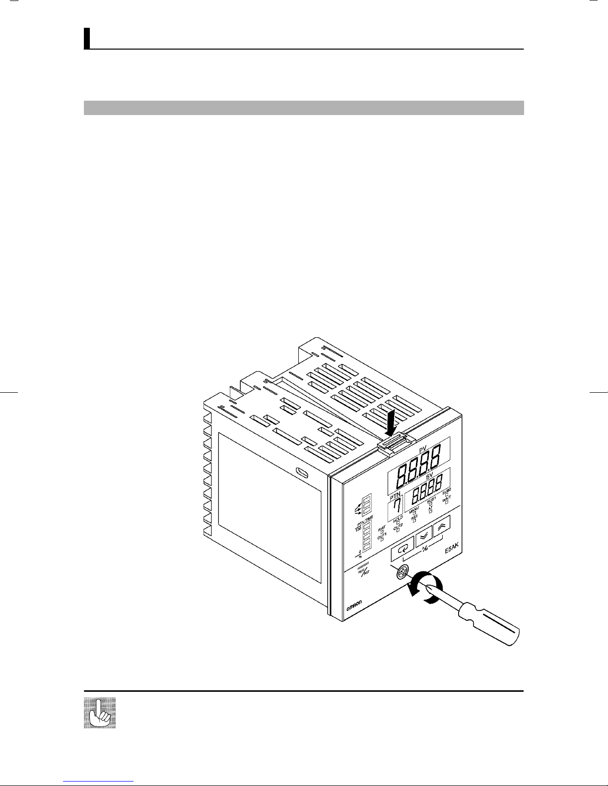
JDraw-out
When drawing out the internal mechanism from the housing, prepare a
Phillips screwdriver matched to the size of the screw on the lower part of
the front panel.
(1) Press down on the hook on the top of the front panel, and turn the
Phillips screwdriver to the left to loosen the screw on the lower part
of the front panel.
Fixing Screw for
Front Panel
2–2
(2) Draw out the internal mechanism towards you holding both sides of
the front panel.
Tighten this screw by a torque of 0.3 to 0.5 N⋅m (approx. 3 to 5 kgf⋅cm).
Page 27
JSetting up the output unit
2.1 Setup
F Before setup
F Procedure
Ă• Check the type of the output unit you are about to set up.
Ă• For details on types of output unit and main specifications, see page 2Ć7.
(1) Check the positions of the sockets you are about to insert the output
units into as shown in the following diagram.
OUT1
OUT2
Bracket
(2) Insert the output unit for control output 1 into the socket OUT1"
and the output unit for control output 2 into the socket OUT2".
(3) Fasten the output units with the bracket (accessory).
2–3
Page 28
CHAPTER 2 PREPARATIONS
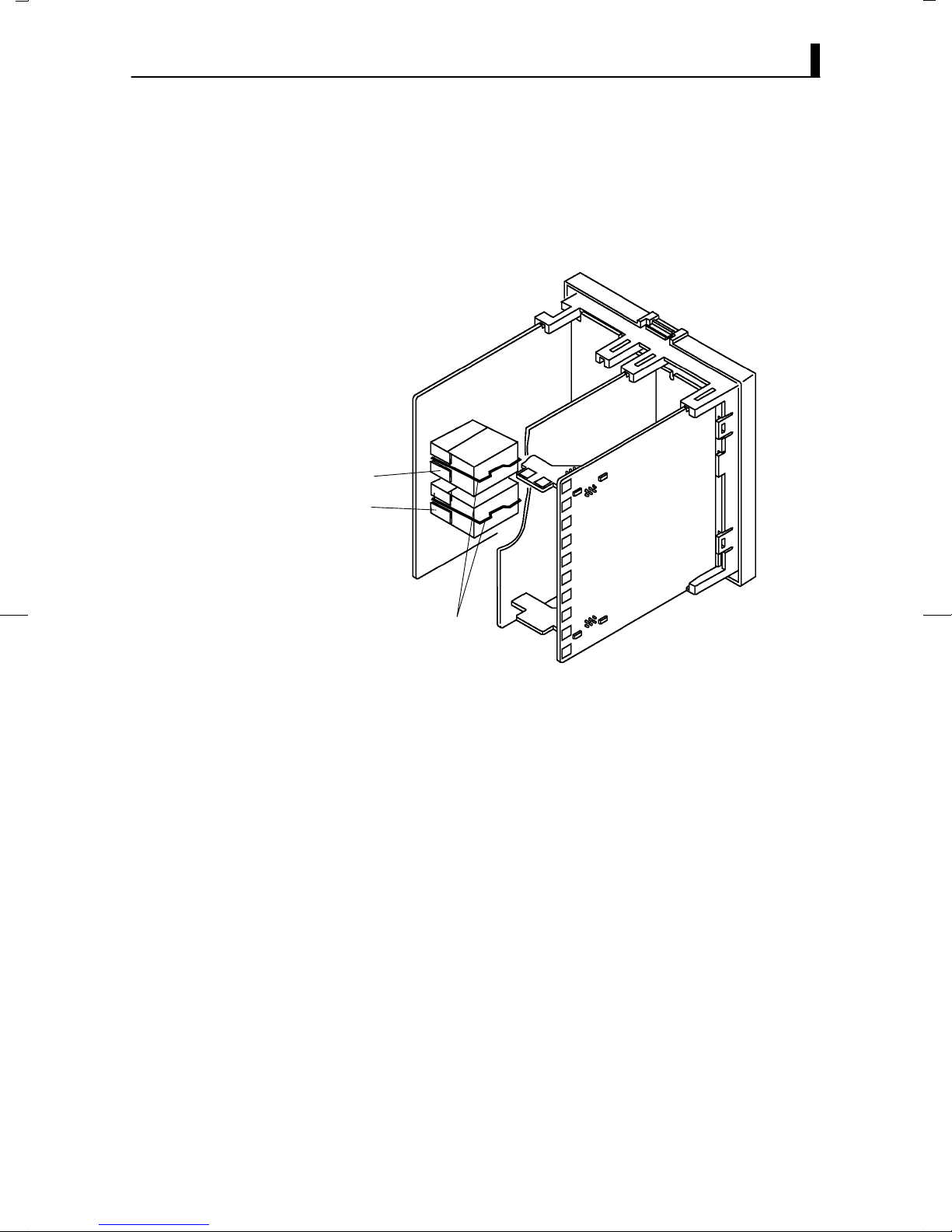
JSetting up the option unit
F Before setup
F Procedure
Ă• Check the type of the option unit you are about to set up.
Ă• For details on types of option unit and main specifications, see Appendix,
Model List (page AĆ12) and Appendix, Option Unit Ratings and CharacĆ
teristics (page AĆ4).
Ă• For details on the relationship between units and terminals, see page
2Ć8.
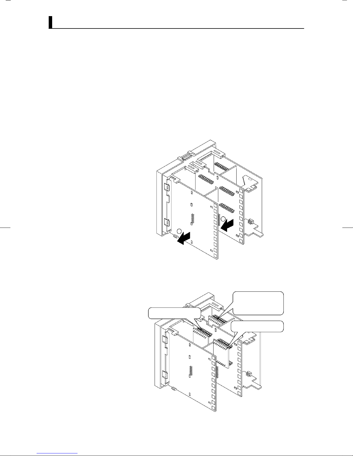
(1) Remove the power board and option boards in the order shown in the
following diagram.
2
1
(2) Insert the option units into the sockets for options 1 to 3. The followĆ
ing diagram shows the relationship between option units and mountĆ
ing positions.
Option 1
E53–AKB: Event inputs 1/2
E53–AK01: RS–232C
Option 2
E53–AKF: Transfer output
E53–AK02: RS–422
E53–AK03: RS–485
Option 3
E53–AKB: Event inputs 3/4
(3) Mount the option boards and the power board in the order shown.
2–4
Page 29
2.2 Installation
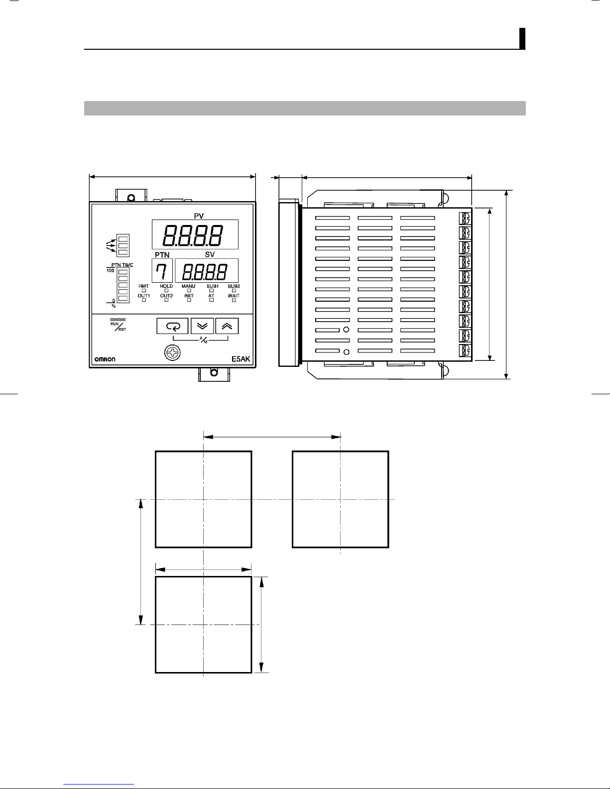
JDimensions
96 13.5 100
2.2 Installation
91
112
JPanel cutout
Unit (mm)
120 min.
92
+0.8
0
110 min.
+0.8
92
Ă• Recommended panel thickness is 1 to 8
mm.
Ă• Maintain the specified vertical and horiĆ
zontal mounting space between each conĆ
0
troller.
Controllers must not be closely mounted
vertically or horizontally.
2–5
Page 30
CHAPTER 2 PREPARATIONS
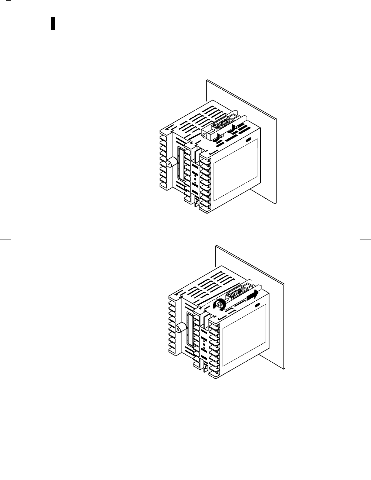
JMounting
(1) Insert the E5AKĆT controller into the mounting hole in the panel.
(2) Fit the mounting bracket (accessory) into the fixing slots on the top
and bottom of the rear case.
(3) Tighten the mounting bracket screws alternately a little at a time unĆ
til the ratchet starts to slide.
2–6
Page 31

F Setting up the terminal covers
Ă• Fasten the terminal covers (E53ĆCOV0809) to protect terminals.
Ă• E5AKĆ2Ć500 controller is provided with terminal covers.
Ă• Use E53ĆCOV09 for terminals 1 to 10, and E53ĆCOV08 for terminals 11
to 33.
Ă• Fasten the terminal covers as follows by using the snap pins.
2.2 Installation
E5AK-T
E53-COV0809
Ă• To remove the terminal covers, pull the edges of the snap pins.
2–7
Page 32

CHAPTER 2 PREPARATIONS
2.3 Wiring Terminals
JTerminal arrangement
TRSF : Transfer output
EV1 to 4 : Event inputs
PTMR : Potentiometer
SOURCE : 100 to 240 VAC, 50/60 Hz 16VA or 24VAC/DC, 50/60 Hz, 12VA 8W
SOURCE
OUT1
OUT2
SUB1
SUB2
10
EV1/2
30
TRSF
9
8
7
6
5
EV3/4
4
3
2
1
29
28
27
26
25
24
23
22
21
31 32
33
20
19
18
17
16
15
14
13
12
11
RS232C
RS422
RS485
CT
PTMR
TC
Pt
I
V
JPrecautions
when wiring
JWiring
F Power supply
10
9
8
7
6
5
4
3
2
1
30
29
28
27
26
25
24
23
22
21
31 32
33
20
19
18
17
16
15
14
13
12
11
Ă• On some models, terminals are not used and are left free. Do not wire
these terminals.
Ă• Separate input leads and power lines in order to protect the controller
and its lines from external noise.
Ă• We recommend using solderless terminals when wiring the controller.
Ă• Tighten the terminal screws using a torque no greater than 0.78 Nm
(8kgfcm).
Ă• Use the following type of solderless terminals for M3.5 screws.
7.2mm max.
7.2mm max.
In the following wiring diagrams, the left side of the terminal Nos. indiĆ
cates the inside of the controller.
Ă• Input power to terminals Nos. 9 and 10. Power specifications are as follows:
100 to 240 VAC, 50/60 Hz, approx. 16 VA
or
24 VAC, 50/60 Hz, approx. 12 VA
24 VDC, 8W
2–8
Page 33

2.3 Wiring Terminals
F Sensor input
10
9
8
7
6
5
4
3
2
1
30
29
28
27
26
25
24
23
22
21
31 32
33
F Control output
10
9
8
7
6
5
4
3
2
1
30
29
28
27
26
25
24
23
22
21
31 32
33
20
19
18
17
16
15
14
13
12
11
20
19
18
17
16
15
14
13
12
11
Ă• Connect the sensor input to terminal Nos. 11 to 14 and 33 as follows acĆ
cording to the input type.
14
13
12
11
33
Thermocouple Platinum
-
+
resistance
thermometer
14
13
12
11
33
+
14
V
13
12
-
11
33
Voltage input Current input
14
13
12
11
33
-
mA
+
Ă• Terminal Nos. 7 and 8 are for control output 1 (OUT1), and terminal Nos.
5 and 6 are for control output 2 (OUT2). The following diagrams show the
available output units and their internal equalizing circuits.
86
75
NPN
E53-Q
E53-Q3
+
L
GND
-
86
75
Relay
E53-R E53-S E53-Q4
+
86
mA V
4 to 20mA/0 to 20mA
E53-C3
E53-C3D
LL
75
-
86
75
SSR PNP
86
75
0 to 10V/0 to 5V
E53-V34
E53-V35
+v
GND
+
-
+v
86
75
+
L
-
Ă• With E53ĆV output units, about 2 V is output for one second after the
power is interrupted.
Ă• The following table shows the specifications for each output unit.
Model Output Type Output Mode Specifications
E53-R Relay Pulse 250 VAC, 5 A
E53-S SSR Pulse 75 to 250 VAC, 1 A
E53-Q
E53-Q3
E53-Q4
E53-C3
E53-C3D
E53-V34
E53-V35
Voltage (NPN)
Voltage (NPN)
Voltage (PNP)
4 to 20 mA
0 to 20 mA
0 to 10 V
0 to 5 V
Pulse
Pulse
Pulse
Linear
Linear
Linear
Linear
NPN : 12 VDC, 40 mA (with short-circuit protection)
NPN : 24 VDC, 20 mA (with short-circuit protection)
PNP : 24 VDC, 20 mA (with short-circuit protection)
4 to 20 mA, Permissible load impedance: 600 Ω max., Resolution: Approx. 2600
0 to 20 mA, Permissible load impedance: 600 Ω max., Resolution: Approx. 2600
0 to 10 VDC, Permissible load impedance: 1 kΩ min., Resolution: Approx. 2600
0 to 5 VDC, Permissible load impedance: 1 kΩ min., Resolution: Approx. 2600
Ă• With E5AKĆTPRR2 controllers, relay output (250 VAC, 1A) is fixed.
When the output unit is replaced, use the E53ĆR. The following diagrams
show the relationship between terminals and open/close relay terminal
settings.
8
7
Open
6
5
Close
2–9
Page 34

CHAPTER 2 PREPARATIONS
F Auxiliary output
10
9
8
7
6
5
4
3
2
1
30
29
28
27
26
25
24
23
22
21
31 32
33
F CT input/
Potentiometer
10
9
8
7
6
5
4
3
2
1
30
29
28
27
26
25
24
23
22
21
31 32
33
20
19
18
17
16
15
14
13
12
11
20
19
18
17
16
15
14
13
12
11
Ă• Terminal Nos.3 and 4 are for auxiliary output 1 (SUB1) and terminal
Nos.1 and 2 are for auxiliary output 2 (SUB2).
Ă• The internal equalizing circuits for the auxiliary outputs are as follows:
4
3
Auxiliary
output 1
2
1
Auxiliary
output 2
Ă• Output specifications are as follows:
SPSTĆNO, 250 VAC, 3 A
Ă• When the HBA function on an E5AKĆTAA2 controller is used, connect
CT input (CT) to terminal Nos.15 and 17. When monitoring the valve
opening on an E5AKĆTPRR2 controller, connect the potentiometer
(PTMR) to terminal Nos.15 to 17. Connect each of these inputs as folĆ
lows:
17
16
CT
15
CT input Potentiometer
17
16
15
O
W
C
Ă• For details on CT inputs, see Appendix, About Current Transformer
(CT) Input (page AĆ5).
Ă• For details on the potentiometer, see the Instruction Manual for the
valve connected to the controller.
The meaning of terminal symbols is as follows:
O: OPEN, W: WIPE, C: CLOSE
The variable resistance range is 100 Ω to 2.5 kΩ.
About Isolation
2–10
The E5AKĆT has independent power supplies
for each of the terminal blocks shown on the
right.
AB C
10
9
8
7
B
6
5
4
E
3
2
1
30
29
28
27
26
C
25
24
23
22
21
31 32
33
20
19
18
17
16
15
14
13
12
11
FD
Page 35

2.3 Wiring Terminals
F Event input
10
9
8
7
6
5
4
3
2
1
30
29
28
27
26
25
24
23
22
21
31 32
33
20
19
18
17
16
15
14
13
12
11
Ă• Connect event inputs 1 and 2 (EV1/2) to terminal Nos.18 to 20, and event
events 3 and 4 (EV3/4) to terminal Nos.24 to 26. However, note that terĆ
minal Nos.18 to 20 cannot be used on controllers supporting the commuĆ
nications function.
Ă• Connect the event inputs as follows:
EV1
EV2
COM
Event input 1 and 2
19
18
+
-
+
20
EV3
EV4
COM
+
26
+
25
24
-
Event input 3 and 4
Terminal Nos.18 and 24 (COM) are connected internally.
Ă• Use event inputs under the following conditions:
Contact input ON: 1 kΩ max., OFF: 100 kΩ min.
No-contact input ON: residual voltage 1.5 V max.,
OFF: leakage current 0.1 mA max.
Ă• Polarities during noĆcontact input are as follows:
+
20
EV1
19
18
+
-
EV2
COM
Event input 1 and 2
EV3
EV4
COM
Event input 3 and 4
26
25
24
+
+
-
F Transfer output
F Communications
Ă• Connect transfer output (TRSF) to terminal Nos. 29 and 30.
Ă• The internal equalizing circuit for transfer output is as follows:
+
30
4 to 20mA L
29
-
Ă• Transfer output specifications are as follows:
4 to 20 mA DC, Permissible load impedance: 600 Ω max., Resolution:
Approx. 2600
Ă• Terminal Nos.18 to 20, 31 and 32 can be used only on controllers that
support the communications units (E53ĆAK01/02/03).
Ă• For details on wiring, see Chapter 6, Using the Communications FuncĆ
tion.
2–11
Page 36

CHAPTER 2 PREPARATIONS
2–12
Page 37

CHAPTER3
CHAPTER 3
BASIC OPERATION
This chapter describes actual examples for understanding the basic opĆ
eration of the E5AKĆT.
3.1 Convention Used in this Chapter 3Ć2. . . . . . . .
3.2 Setting Input Specifications 3Ć4. . . . . . . . . . . . .
Input type 3Ć4. . . . . . . . . . . . . . . . . . . . . . . . . . . . .
CHAPTER 3 BASIC OPERATION
Temperature input 3Ć5. . . . . . . . . . . . . . . . . . . . .
Analog input 3Ć5. . . . . . . . . . . . . . . . . . . . . . . . . .
3.3 Setting Output Specifications 3Ć7. . . . . . . . . . .
Output assignments 3Ć7. . . . . . . . . . . . . . . . . . . .
Direct/reverse operation 3Ć8. . . . . . . . . . . . . . . .
Control period 3Ć8. . . . . . . . . . . . . . . . . . . . . . . . .
3.4 Setting Alarm Type 3Ć10. . . . . . . . . . . . . . . . . . . .
Alarm type 3Ć10. . . . . . . . . . . . . . . . . . . . . . . . . . . .
Alarm value 3Ć10. . . . . . . . . . . . . . . . . . . . . . . . . . .
Alarm hysteresis 3Ć11. . . . . . . . . . . . . . . . . . . . . . .
Close in alarm/open in alarm 3Ć11. . . . . . . . . . . .
3.5 Setting Patterns 3Ć14. . . . . . . . . . . . . . . . . . . . . . .
Pattern No. 3Ć15. . . . . . . . . . . . . . . . . . . . . . . . . . . .
Number of steps 3Ć15. . . . . . . . . . . . . . . . . . . . . . .
Step SP/Step time 3Ć15. . . . . . . . . . . . . . . . . . . . . .
Alarm value 3Ć16. . . . . . . . . . . . . . . . . . . . . . . . . . .
3.6 Protect Mode 3Ć19. . . . . . . . . . . . . . . . . . . . . . . . . .
Security 3Ć19. . . . . . . . . . . . . . . . . . . . . . . . . . . . . . .
Key protect 3Ć19. . . . . . . . . . . . . . . . . . . . . . . . . . . .
3.7 Starting and Stopping Operation 3Ć21. . . . . . . .
3.8 Adjusting Control Operation 3Ć22. . . . . . . . . . . .
Changing currently running programs 3Ć22. . .
Manual operation 3Ć24. . . . . . . . . . . . . . . . . . . . . .
AutoĆtuning (A.T.) 3Ć25. . . . . . . . . . . . . . . . . . . . .
3–1
Page 38
CHAPTER 3 BASIC OPERATION
3.1 Convention Used in this Chapter
This chapter describes basic E5AKĆT operations such as how to set up paĆ
rameters, start and stop operation, and adjust control operation.
For more complex control examples, refer to Chapter 4 Applied Operation
and Chapter 5 Parameters.
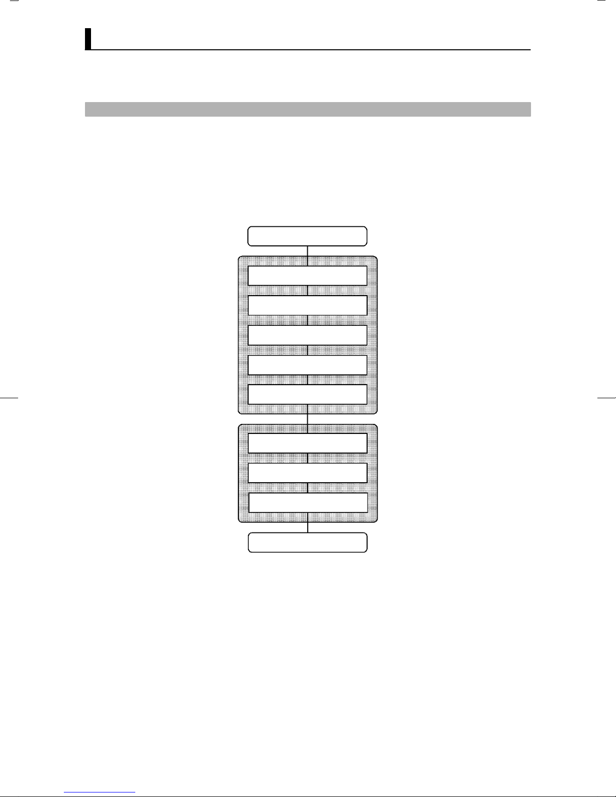
F Basic Operation
Flow
The following diagram shows the basic flow of operation.
Power ON
Setup
Setting input specifications
Setting output specifications
Setting alarm output
Setting patterns
Protecting parameters
Operation
Start
Adjustment
Stop
3–2
Power OFF
The descriptions in this chapter follow the order of basic operations shown
in the flow above. Examples of operation of each of the items are described
up to completion of parameter setup. However, you must move to the top
parameter of the following setting. For example, when you have finished
setting input specifications" and you want to set output specifications,"
move to the top parameter of setting output specifications" from the botĆ
tom parameter of setting input specifications."
For details on moving to parameters between items, refer Chapter, SelectĆ
ing modes and Selecting parameters (page 1Ć10).
Page 39

3.1 Convention Used in this Chapter
F Setup examples
Alarm 2 (upper limit)
(alarm value=10°C)
This description assumes that the controller is operated under the followĆ
ing conditions.
Ă• A K thermocouple is used as the input.
Ă• Control output (heat), alarm 1 and alarm 2 functions are assigned to
control output 1," control output 2" and auxiliary output 1, respecĆ
tively. Of these, only control output 1 and auxiliary output 1 are used.
Ă• The relay output unit is mounted at control output 1.
Ă• The upperĆlimit alarm is set as alarm 2. The alarm is output when the
temperature exceeds 10C with respect to the PV.
Ă• The program is made up of one pattern comprising four steps.
Ă• The following figures show terminal wiring and the program used in the
setting examples.
Temperature sensor:
K thermocouple
Control target
AC100-240V
OUT1
SUB1
10
9
8
7
6
5
4
3
2
1
E5AK-TAA
(Control output 1: E53-R)
30
29
28
27
26
25
24
23
22
21
31 32
33
20
19
18
17
16
15
14
13
12
11
-
4 to 20mA
+
SP
Step 1 Step 2 Step 3
100
Pattern 0
50
0.20 0.40 0.20
Time: hr, min
3–3
Page 40

CHAPTER 3 BASIC OPERATION
3.2 Setting Input Specifications
Setting input specifications
Input type
Temperature input?
Y
Temperature unit
Temperature input shift
End of setup
N
Scaling
Decimal point
Setup mode
Level 2 mode
Ă• With temperature input, scaling and decimal point parameters need not
be set as this information is determined by the input (sensor) type.
(These parameters are not displayed.) Note that temperature unit and
temperature input shift parameters need to be set.
Ă• With analog input, the scaling upper limit", scaling lower limit" and
decimal point" parameters need to be set.
JInput type
3–4
Ă• Set the type No. (0 to 21) in the input type" parameter (Set up mode).
The factory setting is 2: K1 (thermocouple)."
Ă• For details on input types and setting ranges, see page 5Ć31.
Page 41

JTemperature input
F Temperature unit
3.2 Setting Input Specifications
Ă• To switch the temperature unit from C" toF" when input is temperĆ
ature, switch the C/F selection" parameter (setup mode) from "
to ".
F Temperature
input shift
JAnalog input
Ă• When input is temperature input, the upper and lower limit values of the
sensor can be shifted linearly. For example, if both the upper and lower
limit values are shifted by 1.2C, the process value (before shift) is reĆ
garded as 201.2C after shift when input is 200C before shift.
Ă• To set input shift, set shift values in the input shift upper limit" and inĆ
put shift lower limit" parameters (level 2 mode).
Temperature
Input shift upper limit value
Upper limit value
After shift
Before shift
Input shift lower
Lower limit value
0
limit value
Input (%FS)
100
Ă• When the analog input (the voltage input and current input) is selected,
scaling matched to the control is required.
Ă• The scaling upper limit", scaling lower limit" and decimal point" paĆ
rameters (setup mode) are used for scaling. These parameters cannot be
used when the temperature input type is selected.
Ă• The scaling upper limit" parameter sets the physical quantity to be exĆ
pressed by the upper limit value of input, and the scaling lower limit"
parameter sets the physical quantity to be expressed by the lower limit
value of input. The decimal point" parameter sets the number of digits
past the decimal point.
Ă• The following figure shows a scaling example of 4 to 20 mA input. After
scaling, the humidity can be directly read. In this case, the decimal
point" parameter is set to 1".
Readout (humidity)
Scaling upper limit
value (95.0%)
Scaling lower limit
value (10.0%)
0
100%FS
Input (4 to 20 mA)
3–5
Page 42

CHAPTER 3 BASIC OPERATION
Setting Example
1 second min.
1 second min.
1 second min.
In this example, let's check the input type and temperature units, and shift
the lower limit by 1C and the upper limit by 3C.
input type" = 2: K1"
temperature unit" = C"
input shift upper limit" = 3.0"
input shift lower limit" = 1.0"
(1) Select the menu display, and select ăă : setup mode" using the
or keys. For details on selecting the menu display, see page
1Ć10.
(2) Press the key for one second minimum to enter the setup mode.
The top parameter in the setup mode : input type" is displayed.
This parameter is factoryĆset to 2: K1".
(3) Press the key to fix the set value. The display changes to ăă :
C/F selection" parameter. This parameter is factoryĆset to : C".
(4) Select the menu display, and select : level 2 mode" using the
or keys.
(5) Press the key for one second minimum to enter the level 2 mode.
The top parameter in the level 2 mode [ăă ] (local/remote" paĆ
rameter) is displayed.
(6) Press the key until [ ] (input shift upper limit" parameter)
is selected. This parameter is factoryĆset to 0.0".
(7) Press the key until 3.0" is displayed.
(8) Press the key until [ ] (input shift lower limit" parameter)
is selected. This parameter is factoryĆset to 0.0".
(9) Press the key until 1.0" is displayed. This sets the input shift
upper limit" and input shift lower limit" values.
3–6
Page 43

3.3 Setting Output Specifications
Destinati
Some output specifications are different according to controller type,
standard or positionĆproportional. The following table summarizes which
outputĆrelated parameter settings are supported.
3.3 Setting Output Specifications
JOutput assignments
F Standard type
Ă• Thirteen outputs are supported. These functions are assigned to control
Ă• Restrictions on assignment destination are placed on some of the outĆ
Ă• The following table shows where outputs may be assigned to.
Parameter
Control output 1 assignment
Control output 2 assignment
Auxiliary output 1 assignment
Auxiliary output 2 assignment
Direct/reverse operation
Control period (heat)
Control period (cool)
( Indicates that an output specification is supported.)
Standard
Type
Position-
proportional
Type
Output assignments are described according to controller type.
outputs 1 and 2, and auxiliary outputs 1 and 2.
puts.
Assignment
Control Output Auxiliary Output
on
Output Function
Control output (heat)
Control output (cool)
Alarm 1
Alarm 2
Alarm 3
HBA
LBA
Time signal 1
Time signal 2
Program end
Stage output
Error 1 : Input error
Error 2 : A/D convertor error
1 2 1 2
With control output (cool), the conditions for switching from standard control
to heating and cooling control are reached when the output function is assigned
at the cooling side during heating and cooling control.
In other words, heating and cooling control is carried out when control
output (cool) is assigned, and standard control is carried out when outĆ
put is not assigned. For details on heating and cooling control, see ChapĆ
ter 4 Applied Operation/4.1 Selecting the Control Method (page 4Ć2).
3–7
Page 44

CHAPTER 3 BASIC OPERATION
Destinati
Ă• Factory settings are as follows:
control output 1 = Control output (heat)
control output 2 = Alarm 1
auxiliary output 1 = Alarm 2
auxiliary output 2 = Alarm 3
Ă• Output assignments are set in the control output 1 assignment", conĆ
trol output 2 assignment", auxiliary output 1 assignment" and auxilĆ
iary output 2 assignment" parameters (setup mode).
F Position-propor-
tional type
JDirect/reverse
operation
Ă• PositionĆproportional type controllers support nine output functions.
These are assigned to auxiliary outputs 1 and 2.
Ă• Restrictions on assignment destinations are placed on some of the outĆ
puts. The following table shows where outputs may be assigned to.
Assignment
Output Function
Alarm 1
Alarm 2
Alarm 3
Time signal 1
Time signal 2
Stage output
Program end output
Error 1 : Input error
Error 2 : A/D converter error
Ă• Direct operation" (or normal operation) refers to control where the maĆ
nipulated variable is increased according to the increase in the process valĆ
ue. Alternatively, reverse operation" refers to control where the manipuĆ
lated variable is decreased according to the decrease in the process value.
For example, when the process value (PV) (temperature), is lower than
the set point (SP) (temperature), in a heating control system, the manipĆ
ulated variable increases by the difference between the PV and SP valĆ
ues.
Accordingly, this becomes reverse operation" in a heating control sysĆ
tem, or alternatively, direct operation" in a cooling control system.
Ă• Direct/reverse operation is set in the direct/reverse operation" parameĆ
ter (setup mode). Default is : reverse operation".
Control Output Auxiliary Output
on
1 2 1 2
JControl period
3–8
Ă• On positionĆproportional type controllers, this item cannot be set.
Ă• On a standard type controller, when the output unit is for pulse output
such as relay output, set the pulse output cycle (control period). Though
a shorter control period provides better control performance, the conĆ
trol period should be set to 20 seconds minimum taking the life expectanĆ
cy of the output unit into consideration when the output unit is for relay
output.
Ă• The control period is set in the control period (heat)" parameter (level
1 mode). Default of the control period" parameter is factoryĆset to
20:20 seconds." The control period (cool)" output function is not
assigned. So, the control period (cool)" parameter cannot be set.
Page 45

3.3 Setting Output Specifications
Setting Example
1 second min.
1 second min.
1 second min.
All of the above settings in this example are factory settings. In this examĆ
ple, let's check the parameter settings.
In this example, the parameters are set as follows:
control output 1 assignment" = control output (heat)"
auxiliary output 1 assignment" = alarm output 2"
direct/reverse operation" = reverse operation"
control period" = 20 secs"
(1) Select the menu display, and select ĂĂĂ : setup mode" using the
or keys. For details on selecting the menu display, see page
1Ć10.
(2) Press the key for one second minimum to enter the setup mode.
The top parameter in the setup mode : input type" is displayed.
(3) Press the key until [ ] (control output 1 assignment" paĆ
rameter) is displayed. Default is [ ].
(4) As the setting in this example is to be left as it is, press the key
twice. The display changes to [ ] (auxiliary output 1 assignĆ
ment" parameter). Default is [ ].
(5) As the setting in this example is to be left as it is, press the key
until [ ] (direct/reverse operation" parameter) is displayed.
Default is [
(6) As the setting in this example is to be left as it is, press the
].
or
keys to select : level 1 mode". For details on selecting the menu
display, see page 1Ć7.
(7) Press the key for one second minimum to enter the level 1 mode.
The top parameter in the level 1 mode ĂĂĂĂ : Proportional band" is
displayed.
(8) Press the key until [ĂĂĂĂ ] (control period (heat)" parameter)
is displayed. Default is 20". As the setting in this example is to be left
as its is, quit key operation.
3–9
Page 46

CHAPTER 3 BASIC OPERATION
Al
3.4 Setting Alarm Type
Ă• Three alarm outputs are supported: alarms 1 to 3. Of these, only the
alarm assigned as the output can be used.
Ă• Alarm output conditions are determined according to the combination
of the alarm type", alarm value" and alarm hysteresis" parameter
settings.
Ă• The contact conditions for when alarm output is ON can be set to open"
or closed" in the close in alarm/open in alarm" parameter.
JAlarm type
Ă• The following table shows the alarm types supported by the E5AKĆT
controller and their respective operations.
arm Type
Upper-and lower-limit alarm
1
(deviation)
Upper-limit alarm
2
(deviation)
Lower-limit alarm
3
(deviation)
Upper-and-lower-limit range
alarm
4
(deviation)
Upper-and-lower-limit alarm
with standby sequence
5
(deviation)
Upper-limit alarm with stand-
by sequence
6
(deviation)
Lower-limit alarm with stand-
7
by sequence
Absolute-value upper-limit
8
alarm
Absolute-value lower-limit
9
alarm
Absolute-value upper-limit
10
alarm with standby sequence
Absolute-value lower-limit
11
alarm with standby sequence
When X is positive When X is negative
ON
OFF
ON
OFF
ON
OFF
ON
OFF
ON
OFF
ON
OFF
ON
OFF
ON
OFF
ON
OFF
ON
OFF
ON
OFF
Alarm Output Operation
XX
SP
X
SP
X
SP
XX
SP
XX
SP
X
SP
X
SP
X
0
X
0
X
0
X
0
Always ON
ON
OFF
ON
OFF
Always OFF
Always OFF
ON
OFF
ON
OFF
ON
OFF
ON
OFF
ON
OFF
ON
OFF
X
SP
X
SP
X
SP
X
SP
X
0
X
0
X
0
X
0
Ă• Alarm types are set independently for each alarm in the alarm 1 to 3"
parameters (setup mode). Default is 2: UpperĆlimit alarm (devicaĆ
tion)".
JAlarm value
3–10
Ă• Alarm values are indicated by X" in the table above. Alarm output opĆ
eration differs according to whether the value of the alarm is positive or
negative.
Ă• Alarm values are built into the program and are set for each pattern. For
details, see 3.5 Setting Patterns" (page 3Ć14).
Page 47

3.4 Setting Alarm Type
Cl
O
JAlarm hysteresis
F Standby
sequence
Ă• The hysteresis of alarm outputs when alarms are switched ON/OFF can
be set as follows:
Upper lim i t a l a r m Lower limit alarm
ON
OFF
Alarm hysteresis
Alarm value
ON
OFF
Alarm value
Alarm hysteresis
Ă• Alarm hysteresis is set independently for each alarm in the alarm 1 to
3 hysteresis" parameters (level 2 mode). Default is 0.02: 0.02%FS".
Ă• Standby sequence" is a function for unconditionally turning alarm outĆ
put OFF when the process value has left the alarm range once and it next
enters the alarm range.
Ă• For example, when the alarm type is set to lowerĆlimit alarm," generalĆ
ly the process value is within the alarm range, and alarm output smaller
than the set point, and alarm output becomes ON when this state continĆ
ues. However, if the alarm type is set to lowerĆlimit alarm with standby
sequence", alarm output first becomes ON when the process value exĆ
ceeds the alarm setting value to leave the alarm range and once again
falls below the alarm value.
Ă• The standby sequence is canceled when an alarm is output. It is, howevĆ
er, restarted later by one of the following conditions:
Operation is started or power is turned ON.
A pattern is started.
The program advances to the next step.
The SP of the current step is changed.
The currently running alarm value is changed.
The input shift value is changed.
Advance is executed.
JClose in alarm/open in alarm
Ă• When the controller is set to close in alarm," the status of the alarm outĆ
put function is output as it is. When set to open in alarm," the status
of the alarm output function is output inverted.
Output Output LED
ose in alarm
pen in alarm
Alarm
ON ON Lit
OFF OFF Not lit
ON OFF Lit
OFF ON Not lit
Ă• Alarm type and close in alarm (normally open)/open in alarm (normally
close) can be set independently for each alarm.
Ă• Close in alarm/open in alarm is set in the alarm 1 to 3 open in alarm"
parameters (setup mode). Default is ĂĂ : close in alarm".
3–11
Page 48

CHAPTER 3 BASIC OPERATION
F Summary of
alarm operations
The figure below visually summarizes the above descriptions of alarm opĆ
erations (when alarm type is set to lowerĆlimit alarm with standby seĆ
quence"):
Alarm type: lower limit alarm with
standby sequence
PV
Alarm value
Alarm hysteresis
Time
Standby sequence
canceled
Alarm
output
ON
OFF
ON (closed)
OFF (open)
3–12
Page 49

3.4 Setting Alarm Type
Setting Example
1 second min.
1 second min.
Alarm 2 is output when the temperature exceeds alarm value 2 proĆ
grammed to the SP. Parameter factory settings for alarm type 2," alarm
hysteresis" and close in alarm/open in alarm" are used.
In this example, the related parameters are set as follows:
alarm type 2" = 2: upperĆlimit"
alarm value 2" = (set in program setting)
alarm hysteresis: = 0.02"
close in alarm/open in alarm" = : close in alarm"
In this example, let's check the alarm type.
(1) Select the menu display, and select ĂĂ : setup mode" pressing the
or keys. For details on selecting the menu display, see page
1Ć9.
(2) Press the key to enter the setup mode. The top parameter in the
setup mode : input type" is displayed.
(3) Press the key until [ ] (alarm type 2" parameter) is disĆ
played. Default is 2: upper limit".
1 second min.
3–13
Page 50

CHAPTER 3 BASIC OPERATION
3.5 Setting Patterns
If you want to set parameters in the program mode during controller operation, you must first stop operation.
Operation may continue only in special instances, for example, to change SP during controller operation.
Ă• Parameters that you use frequently for programming can be set in the
program mode." The flow below shows the parameters that are availĆ
able in the program mode and the order in which they are set.
Select the program mode.
Select pattern No.
Set number of steps
Step time/Rate of rise
programming
Step time setting
Set step SP/step time
Set pattern execution count
Set alarm value
Set time signal 1, 2
Step/ON time/OFF time
n
All patterns completed?
Rate of rise setting
Set SP/Ramp time
/Soak time of each step
y
3–14
End of program
This chapter describes the basic operation of programming. For details on
the following parameters, refer to Chapter 4 Applied Operation:
Step time/Rate of rise programming", Pattern execution count", Time
signal 1, 2"
Page 51

3.5 Setting Patterns
JPattern No.
JNumber of steps
JStep SP/Step
time
: 0 to 15
Ă• This parameter cannot be changed during controller operation.
Ă• Set the desired pattern No. Step SP, step time, alarms and other parameĆ
ters that follow this parameter are set for the pattern that is set in this
parameter.
Ă• Set within the range 0 to 7 (pattern 0 to 7). Default is 0".
Ă• Set the number of steps for the pattern that you specified in the pattern
No." parameter.
Ă• Set within the range 1 to 16 (step). Default is 8".
Ă• Set only the number of steps used in the program in order from step 0,
as step 0 SP", step 0 time", step 1 SP", step 1 time" and so forth.
Ă• Set within the range from set point lower limit to set point upper limit
for step SP. Default is 0".
Ă• Set within the range 0.00 to 99.59 (hours:minutes or minutes:seconds).
Default is 0.00".
SP
Step 0 Step 1 Step 2 Step 3
B
A
Step 0 time
A: SP of steps 0 and 3
B: SP of steps 1 and 2
Ă• As shown in the above figure, step 0 is a fixed value, so when ramp operaĆ
tion is started, set the step 0 time" parameter to 0.00" to configure the
program so that ramp operation starts from step 1.
Step 1 time Step 2 time Step 3 time
Time
3–15
Page 52

CHAPTER 3 BASIC OPERATION
JAlarm value
: 0 to 3
Ă• Alarm values can be set only for alarms that have been assigned as outĆ
put.
Ă• When a deviation alarm is assigned as output, the alarm value is set with
respect to SP. The following example shows the relationship between the
SP and alarm value when the alarm type is set to upper limit."
SP
Step 0 Step 1 Step 2
Step 1 SP
Step 0 SP
Alarm type: upper-limit alarm
Alarm value
Time
About the Alarm
Value Decimal
Point
3–16
The decimal point of the alarm value conforms to the setting of the decimal point"
parameter.
Page 53

3.5 Setting Patterns
Setting Example
1 second min.
In this example, let's set the next program to pattern 0.
SP
100
50
Step 0 50 0.00 10
Step 1 100 0.20 10
Step 2 100 0.40 10
Step 3 50 0.20 10
Step 1 Step 2 Step 3
0.20 0.40 0.20
SP
Time
(hr, min.)
Alarm
value 2
Ă• Pattern execution count 1"
Ă• Time signals are not used.
Time: hr, min
(1) Select the menu display, and select : program" pressing the
or keys. For details on selecting the menu display, see page 1Ć10.
(2) Press the key to enter the program mode. The top parameter in
the program mode
: pattern" is displayed. Default is 0 : patĆ
tern 0".
(3) As the setting 0: pattern 0" in this example is to be left as it is, press
the
key. The display changes to the [ ] (number of steps" paĆ
rameter). Default is 8".
(4) Set the parameter to 4" pressing the or keys.
(5) When you press the , the display changes to the [ ] (step 0 SP"
parameter). Default is 0".
(6) Set the parameter to 50" pressing the or keys.
(7) When you press the , the display changes to the [ ] (step 0
time" parameter). Default is 0.00".
(8) As the setting 0.00: 0 minutes" in this example is to be left as it is,
press the key. The display changes to the [ ] (step 1 SP" paĆ
rameter). Default is 0".
(9) Set the parameter to 100" pressing the or keys.
(10) In the same way, set the : step 1 time", : step 2 SP",
: step 2 time", : step 3 SP", : step 3 time" parameters, in
that order.
(11) When you have finished setting the step SPs and times press the
key. The [ ] (pattern execution count" parameter, is displayed.
Default is 1".)
3–17
Page 54

CHAPTER 3 BASIC OPERATION
(12) As the setting in this example is to be left as it is, set the alarm value.
(13) Set the parameter to 10: 10 seconds" pressing the or keys.
Press the key until [ ] (alarm 2" parameter) is displayed.
Default is 0".
3–18
Page 55

3.6 Protect Mode
Mod
3.6 Protect Mode
JSecurity
Ă• This parameter allows you to protect until start of operation parameters
that do not change during operation to prevent unwanted modification.
Ă• The set value of the security" parameter (protect mode) limits the
range of protectable parameters. The following table shows the relationĆ
ship between set values and the range of protection. (Only modes
marked by can be operated.)
e
Calibration
Option
Expansion
Setup
Level 2
Level 1
Program
Level 0 *1
*1 Only the PV/Present SP” parameter can be displayed.
Ă• When this parameter is set to 0", parameters are not protected.
Ă• When this parameter is set to 5", operations in only the level 0 mode can
be selected, and the mode is not displayed on the menu display.
Ă• When this parameter is set to 6", the PV/Present SP" parameter can
only be monitored.
Ă• Default is 1".
0 1 2 3 4 5 6
Set value
JKey protect
Ă• This parameter disables key operation for switching run/reset or auto/
manual. For example, if you protect the key operation for switching
auto/manual by the key protect" parameter (protect mode) during auĆ
tomatic operation, the controller cannot be set to the manual mode, preĆ
venting manual operation of the controller during operation.
Ă• The following table shows the relationship between set values and keys
that are protected.
Set value
0
1
2
3
Ă• Default is 0 : All keys can be operated."
Key protection OFF
A/M cannot be selected.
RUN/RST cannot be selected.
Both A/M and RUN/RST cannot be selected.
Description
3–19
Page 56

CHAPTER 3 BASIC OPERATION
Setting Example
1 second min.
1 second min.
RUN/RST
RUN/RST
In this example, let's set the parameters as follows:
Security" 2" (all parameters in modes other than the setup
mode are protected)
Key protect" 1" (Auto/manual key operation cannot be switched)
(1) Press the
RUN/RST
and keys simultaneously for 1 second miniĆ
mum. The controller enters the protect mode. In the protect mode, the
top parameter in the protect mode security" is displayed.
Default is 1".
(2) Press the key to change the parameter setting to 2".
(3) Press the key to switch to the key protect" parameter.
(4) Press the key to change the parameter setting to 1".
(5) Press the and
RUN/RST
keys simultaneously for 1 second miniĆ
mum. The display changes to the PV/Present SP monitor" parameĆ
ter (level 0 mode).
3–20
Page 57

3.7 Starting and Stopping Operation
3.7 Starting and Stopping Operation
Ă• To start program operation (that is, switch from the reset state to run
RUN/RST
operation), press the
Ă• To stop program operation (that is, switch from run operation to the reĆ
set state), press the
controller has stopped operating (reset state), the RST" LED lights.
Ă• The controller cannot be reset during autoĆtuning (A.T.).
RUN/RST
RUN/RST
key for one second minimum.
key from two seconds minimum. When the
F Manipulated vari-
able at reset
Ă• On a standard type controller, specify the manipulated variable (Ć5.0 to
105.0%) in the MV at reset" parameter (level 2 mode) to output the maĆ
nipulated variable during reset. Default is 0.0:0.0%".
Ă• When the controller is reset in the manual mode, the manual MV takes
precedence.
Ă• Both the MV limitter and MV change rate limitter are ineffective against
the manipulated value at reset.
Ă• On a positionĆproportional type controller, you can select either of the
open, closed or hold state. In an open state, only control output 1 is ON.
In a closed state, only control output 2 is ON. In a hold state, both control
outputs 1 and 2 are OFF. Default is ".
Using Event Input
On the E53ĆAKB, run/reset can be selected by event input.
For details on how to use event input, see 4.8 How to Use Event Input, page 4Ć21.
3–21
Page 58

CHAPTER 3 BASIC OPERATION
3.8 Adjusting Control Operation
JChanging cur-
rently running
programs
F Changing the SP
Before change
After change
Ă• Programs are changed in the program mode. Note that pattern Nos. canĆ
not be changed during program operation. So, only the pattern that is
currently running can be changed.
Ă• You cannot change the program when the security" parameter (protect
mode) is set to 5" or 6".
Ă• Change the SP of steps 0 to 15 in step 0 to 15 SP" parameters (program
mode).
Ă• When the SP is changed midway through a step, the Present SP is shifted
on a line obtained by taking the new SP as the target point.
SP
Changing point
Time
Step N Step N+1
F Changing the
time value
Before change
After change
About Changing
the Number of
Steps
Ă• Change the time value of steps 0 to 15 in step 0 to 15 time" parameters
(program mode).
Ă• When the time value is changed midway through a step, the step time
changes. The gradient of the line by which SP shifts also changes.
SP
Changing point
Time
Step N Step N+1
Step N Step N+1
If you set the number of steps" parameter (program mode) to a value smaller than
the current number of steps during program operation, program operation is imĆ
mediately exited.
3–22
Page 59

3.8 Adjusting Control Operation
Setting Example
1 second min.
1 second min.
In the following example, let's change the temperature set point to 60C"
from 50C".
(1) Press the key for 1 second minimum at the currently executing
PV/Present SP" display.
(2) The display changes to the menu display.
(3) Set the parameter to : program" pressing the or keys.
(4) Press the key to enter the program mode. The top parameter in
the program mode : pattern" is displayed.
(5) Press the key to display the [ ] (number of steps" parameĆ
ter).
(6) Press the key. [ ] (step 0 SP" parameter) is displayed, and the
No.2 display indicates 50.0".
(7) Press the key to set the parameter to "60.0".
(8) Press the key for 1 second minimum. The menu display (
: program" parameter) is redisplayed.
(9) Select : level 0 mode" pressing the or keys, and press
the key for 1 second minimum. The PV/Present SP" display is
redisplayed.
1 second min.
1 second min.
3–23
Page 60

CHAPTER 3 BASIC OPERATION
JManual operation
F Standard type
Ă• On a standard type controller, the manipulated variable is controlled,
and on a positionĆproportional type controller, the valve opening is conĆ
trolled.
Ă• To set manual operation and manually set the manipulated variable or
the valve opening, press the key and key simultaneously for 1
second minimum. Then the controllers enters the manual mode. To quit
the manual mode, press the key and key again simultaneously
for 1 second minimum. The controller enters the level 0 mode without
entering the menu display.
Ă• Though the control shifts to manual operation if the controller is set to
the manual mode during program operation, the program advances.
When program operation is started in the manual mode, program also
advances.
Ă• In the manual mode, the automatic return of display mode does not
work.
Ă• The process value is displayed on the No.1 display, and the manipulated
variable is displayed on the No.2 display.
Ă• To change the manipulated variable, press the or keys. After
two seconds, the manipulated variable is updated to the new setting.
Ă• When switching between manual and auto operation, the manipulated
variable is subject to balanceĆless, bumpĆless operation.
Ă• If the power is interrupted during manual operation, manual operation
is resumed at the manipulated variable that was active at power interĆ
ruption when the power is reset.
Manipulated variable (%)
Manual
Auto
F Position-propor-
tional type
Balance-less,
Bump-less Operation
Balance-less,
bump-less points
0
Manipulated variable switched
++
OFF ON
Power interruption
Time
Ă• When a potentiometer is connected to the controller, the process value
is displayed on the No.1 display, and the valve opening is displayed on the
No.2 display.
Ă• When you press the key, the open side becomes ON. When you press
the key, the close side becomes ON.
To prevent sudden changes in the manipulated variable when switching between
manual and auto operation, operation is resumed using the value that was active imĆ
mediately before operation was switched, and the value is brought gradually closer
to the value immediately after operation was switched.
3–24
Page 61

3.8 Adjusting Control Operation
JAuto-tuning
(A.T.)
F 40%AT
Deviation at start of AT
execution y 10% FS
Ă• AT (autoĆtuning) cannot be executed while operation is reset or during
ON/OFF control.
Ă• When you execute autoĆtuning, the optimum PID parameters are autoĆ
matically set by forcibly changing the manipulated variable to calculate
the characteristics (called the limit cycle method") of the control target.
During autoĆtuning, time counting is stopped and the AT" LED flashes.
Ă• 40%AT or 100%AT can be selected by the limit cycle of MV change width.
Specify [ ] or [ ], respectively, in the AT execute/cancel" paĆ
rameter (level 1 mode).
Ă• During heating and cooling control on a standard type controller, and on
a positionĆproportional type controller, only 100%AT can be executed.
(So, : 40%AT" is not displayed.)
Ă• To cancel AT execution, specify ĂĂĂ : AT cancel".
In order to set the limit cycle of MV change width to 40%, select 40%AT
to execute autoĆtuning with fluctuations in the process value kept to a
minimum. However, note that autoĆtuning takes longer to execute
compared with 100%AT.
The timing by which limit cycles are generated varies according to whether
or not the deviation (DV) at the start of AT execution is 10% fullĆscale or less.
Deviation at start of AT
execution < 10% full-scale
Limit cycle of MV change
width 40%
Limit cycle of MV change
width 40%
Set point Set point
Deviation 10%
full-scale
Start of AT
execution
F 100%AT
End of AT
execution
In order to set the limit cycle of MV change width to 100%, select 100%AT
Time Time
to shorten the AT execution time without worrying about fluctuations in
the process value.
Limit cycle of MV
change width 100%
Set point
Start of AT
execution
Deviation 10%
full-scale
End of AT
execution
Start of A T
execution
End of A T
x
i
Time
n
3–25
Page 62

CHAPTER 3 BASIC OPERATION
Setting Example
1 second min.
AT execute
End of AT execution
In this example, let's execute 40%AT.
(1) Select the menu display, and select : level 1 mode" using the
or keys. For details on selecting the menu display, see page
1Ć10.
(2) Press the key to enter the level 1 mode. The top parameter in the
setup mode ĂĂĂĂ : AT execute/cancel" is displayed. In this example,
the parameter setting is ĂĂĂ : AT cancel".
(3) Press the key to specify : 40%AT".
(4) The AT LED flashes, and AT execution starts. When the AT LED goes
out (end of AT execution), the parameter automatically returns to
ĂĂĂ : AT cancel".
3–26
About PID Parameters
AT Execution Timing
When control characteristics are already known, the PID parameters can be set diĆ
rectly to adjust control.
PID parameters are set in the proportional band" (P), integrated time" (I) and
derivative time" (D) parameters (level 1 mode).
For details on the setting ranges of these parameters, see chapter 5 Level 1 Mode
(page 5Ć18).
The E5AKĆT differs from fixedĆvalue type controllers in that the SP changes autoĆ
matically. So, the timing of AT execution is the most important factor in control.
To obtain PID parameters for a specific SP, make a fixedĆvalue program as follows
and execute AT.
10 minutes
100
Step 0
Set value
SP Time
Step 0 100 0.10
Page 63

CHAPTER4
CHAPTER 4
APPLIED OPERATION
This chapter describes each of the parameters required for making full
use of the features of the E5AKĆT.
Read this chapter while referring to the parameter descriptions in chapĆ
ter 5.
CHAPTER 4 APPLIED OPERATION
4.1 Selecting the Control Method 4Ć2. . . . . . . . . . . .
Heating and cooling control 4Ć2. . . . . . . . . . . . .
PositionĆproportional control 4Ć4. . . . . . . . . . . .
ON/OFF control 4Ć5. . . . . . . . . . . . . . . . . . . . . . .
4.2 Operating Condition Restrictions 4Ć7. . . . . . . .
Manipulated variable restrictions 4Ć7. . . . . . . .
Set point limiter 4Ć8. . . . . . . . . . . . . . . . . . . . . . .
4.3 Ramp Rise Rate Setup Program 4Ć9. . . . . . . . .
Running the ramp rise rate setup program 4Ć11
Program example 4Ć12. . . . . . . . . . . . . . . . . . . . . .
4.4 Program Operation 4Ć13. . . . . . . . . . . . . . . . . . . .
Hold/Advance 4Ć13. . . . . . . . . . . . . . . . . . . . . . . . . .
Pattern operation 4Ć14. . . . . . . . . . . . . . . . . . . . . .
4.5 Wait Operation 4Ć16. . . . . . . . . . . . . . . . . . . . . . . .
4.6 Program output 4Ć17. . . . . . . . . . . . . . . . . . . . . . . .
Time signal 4Ć17. . . . . . . . . . . . . . . . . . . . . . . . . . . .
Program output 4Ć18. . . . . . . . . . . . . . . . . . . . . . . .
4.7 Setting Running Conditions 4Ć19. . . . . . . . . . . . .
Operation at power ON 4Ć19. . . . . . . . . . . . . . . . .
Starting the program run 4Ć19. . . . . . . . . . . . . . .
End condition 4Ć20. . . . . . . . . . . . . . . . . . . . . . . . .
4.8 How to Use Event Input 4Ć21. . . . . . . . . . . . . . . .
Input assignments 4Ć21. . . . . . . . . . . . . . . . . . . . .
Detailed description of input functions 4Ć22. . .
4.9 How to Use the Heater Burnout Alarm 4Ć23. . .
Heater burnout detection 4Ć23. . . . . . . . . . . . . . .
Operating conditions 4Ć23. . . . . . . . . . . . . . . . . . .
How to calculate the heater burnout
set value 4Ć24. . . . . . . . . . . . . . . . . . . . . . . . . . . . . .
4.10 LBA 4Ć26. . . . . . . . . . . . . . . . . . . . . . . . . . . . . . . . . .
4.11 How to Use Transfer Output 4Ć28. . . . . . . . . . . .
4–1
Page 64

CHAPTER 4 APPLIED OPERATION
4.1 Selecting the Control Method
JHeating and
cooling control
When selecting the control method, set the parameters according to the
following table. (Parameters are factoryĆset to heating control.)
Parameter
Control
Method
Heating control
(Standard)
Cooling control
(Standard)
Heating and cooling
control
(Parameters are factoryĆset to heating control.)
Ă• For details on how to assign outputs, see 3.3 Setting Output SpecificaĆ
tions (page 3Ć7).
Ă• When heating and cooling control is selected, the dead band" and coolĆ
ing coefficient" parameters can be used.
F Dead band
The dead band is set with the set point as its center. The dead band width
is the set value of the dead band" parameter (level 1 mode). Setting a posiĆ
tive value produces a dead band, while setting a negative value produces
an overlap band.
The dead band is factoryĆset to 0.00:0.00%FS."
Output Output
Dead band: dead
band width = positive
Control Output 1
Assignment
Control output (heat)
Control output (heat)
Control output (heat) Control output (cool) Reverse operation
Control Output 2
Assignment
-
-
Overlap band: dead
band width = negative
Direct/Reverse
operations
Reverse operation
Direct operation
Heating
side
0
F Cooling
coefficient
Cooling
side
PV
Set point Set point
Heating
side
0
If the heating and cooling characteristics of the control target greatly difĆ
fer, preventing satisfactory control characteristics from being obtained by
the same PID parameters, adjust the proportional band (P at cooling side)
using the cooling coefficient to balance control between the heating and
cooling sides. In heating and cooling control, P at the heating or cooling
side is calculated by the following formula:
Heating side P = P; Cooling side P = cooling coefficient P
Cooling
side
PV
4–2
Page 65

4.1 Selecting the Control Method
F Manipulated vari-
able at reset
Ă• In heating and cooling control, the manipulated variable output that is
output when controller operation is stopped is dependent on the set valĆ
ue of the MV at reset" parameter (level 2 mode) in the same way as for
standard control.
Ă• However, note that in heating and cooling control, the manipulated variĆ
able at the cooling side is treated as a negative value for the sake of conveĆ
nience. When the manipulated variable at reset is a negative value, the
manipulated variable is output to only the cooling side, and when a posiĆ
tive value, the manipulated variable is output to only the heating side.
Default is 0". If the controller is operated with default, the manipulated
variable is not output to both the heating and cooling sides.
Switching with
Manual Operation
When the overlap band is set, the bumpless function that operates when switching
between manual and automatic operation may not work.
4–3
Page 66

CHAPTER 4 APPLIED OPERATION
JPosition-propor-
tional control
8
Open
7
6
Close
5
O
17
W
16
C
15
Potentiometer
F Travel time
F Valve opening
monitor
Ă• Use the positionĆproportional type controller for positionĆproportional
control.
Ă• On a positionĆproportional type controller, control output 1 is used for
open output, and control output 2 is used for closed output. Accordingly,
control outputs 1 and 2 cannot be used as output assignments. Special
output units are already set on positionĆproportional type controllers.
Ă• On a positionĆproportional type controller, the following functions are
disabled:
MV limitter
P and PD control
40% AT
LBA
HBA
ON/OFF control
Ă• To change the travel time, either set in the travel time" parameter (opĆ
tion mode), or execute motor calibration in the motor calibration" paĆ
rameter (option mode).
Ă• Default is 30:30 seconds."
Ă• The valve opening can be monitored when a potentiometer is connected
to the controller. However, be sure to execute motor calibration after
connecting the potentiometer.
F Manipulated vari-
able at reset/PV
error
F Other functions
Ă• Open, closed or hold can be selected as output at reset or PV error. Set
these outputs in the MV at reset" or MV at PV error" parameters (levĆ
el 2 mode).
Ă• Set the dead band in the positionĆproportional dead band" parameter
(level 1 mode). Default is 2.0:2.0%".
Ă• Set the open/close hysteresis in the open/close hysteresis" parameter
(level 2 mode).
Open/close hysteresis
Dead band
ON
OFF
MV-Valve opening
100%0-100%
4–4
Page 67

4.1 Selecting the Control Method
JON/OFF control
F Hysteresis
Ă• Switching between advanced PID control and ON/OFF control is carĆ
ried out by the PID/ON/OFF" parameter (expansion mode). When this
parameter is set to [ĂĂĂ ], advanced PID control is selected, and when
set to [ ], ON/OFF control is selected. Default is [ĂĂĂ ].
Ă• During positionĆproportional control, ON/OFF control cannot be seĆ
lected.
Ă• In ON/OFF control, hysteresis is provided in the program when switchĆ
ing between ON and OFF to stabilize operation. The hysteresis width
provided during ON/OFF control is simply referred to as hysteresis."
Control output (heat) and control output (cool) functions are set in the
hysteresis (heat)" and hysteresis (cool)" parameters, respectively.
Ă• In standard control (heating or cooling control), hysteresis can be set
only for the heating side.
Hysteresis (heat)
ON
OFF
Set point
PV
Ă• In heating and cooling control, a dead band can be set. So, 3Ćposition conĆ
trol is made possible.
Dead band
Hysteresis (heat)
ON
Heating
side
OFF
Hysteresis (cool)
Cooling side
PV
Set point
4–5
Page 68

CHAPTER 4 APPLIED OPERATION
Parameters
Symbol Parameter Name: Mode Description
Control output 1
assignment : Setup
Control output 2
assignment : Setup
Direct/reverse
operation : Setup
Dead band : Level 1 Heating and cooling control
Cooling coefficient : Level 1 Heating and cooling control
MV at reset : Level 2 Manipulated variable when control
MV at PV error : Level 2 Manipulated variable when control
Travel time : Option Position-proportional control
Motor calibration : Option Position-proportional control
Positional-proportional
dead band : Level 1
Open/close
hysteresis : Level 2
Hysteresis (heat) : Level 1 ON/OFF control
Hysteresis (cool) : Level 1 ON/OFF control
PID / ON/OFF : Expansion ON/OFF control
For specifying control method
For specifying control method
For specifying control method
operation is stopped
operation is PV error
Position-proportional control
Position-proportional control
4–6
Page 69

4.2 Operating Condition Restrictions
4.2 Operating Condition Restrictions
JManipulated vari-
able restrictions
F MV limiter
The upperĆ and lowerĆlimit values of the manipulated variable can be reĆ
stricted by the MV limitter, and the change rate of manipulated variable
can be restricted by the MV change rate limitter.
The upperĆ and lowerĆlimit values of the manipulated variable are set in
the MV upper limit" and MV lower limit" parameters (level 2 mode).
When the manipulated variable calculated by the E5AKĆT is outside of the
range of the MV limitter, actual outputs are dependent on the set value of
these parameters.
Output (%)
100
0
MV upper limit value
MV lower
limit value
PV
In heating and cooling control, the manipulated variable at the cooling
side is treated as a negative value for the sake of convenience. The upper
limit is set for the heating side (positive value), and the lower limit is set
for the cooling side (negative value) as shown in the following figure.
F MV change rate
limiter
Output (%)
100
MV lower limit value
MV upper limit value
Heating
side
0
Set point
Cooling
side
PV
The MV change rate limitter" parameter (level 2 mode) sets the maxiĆ
mum permissible change width per second of the manipulated variable. If
a change in the manipulated variable exceeds this parameter setting, the
value calculated by the E5AKĆT is reached while changing the value by the
perĆsecond value set in this parameter.
Output (%)
100
MV change rate
limit value
1 second
0
Switching point
Time
4–7
Page 70

CHAPTER 4 APPLIED OPERATION
F Limiter operation
conditions
JSet point limiter
Set point Upper-and lower-limit values of the limitter
Scaling (sensor) upper-and lower-limitter values
The limitters are disabled or cannot be set when any of the following
conditions occurs:
Ă• During ON/OFF control
Ă• During AT execution (only by MV change rate limitter)
Ă• During manual operation
Ă• When operation is stopped
Ă• When an error has occurred
Ă• During positionĆproportional control (manipulated variable limitter
only)
The setting range of the set point is limited by the set point limitter. The
upperĆ and lowerĆlimit values of this set point limitter are set in the set
point upper limit" and set point lower limit" parameters (expansion
mode), respectively. However, note that when the set point limitter is reset,
the set point is forcibly changed to the upperĆ or lowerĆlimit value of the
set point limitter if the set point is out of the limitter range. Also, when the
input type, temperature unit and scaling (sensor) range are changed, the
set point limitter is forcibly reset to the scaling (sensor) range.
Scaling (sensor) range
Set point limiter
Setting range
Changed to upper
limit value
Input type changed
Changed t o
the new upper limit
value
A
ĘB
C
CB
(setting impossible)
(setting possible)
Ę
Set Point
Set Point
Set Point
Parameters
4–8
Symbol Parameter Name: Mode Description
MV upper limit : Level 2 For limiting manipulated variable
MV lower limit : Level 2 For limiting manipulated variable
MV change rate limit : Level 2 For limiting manipulated variable
Set point upper limit : Expansion For limiting SP setting
Set point lower limit : Expansion For limiting SP setting
Page 71

4.3 Ramp Rise Rate Setup Program
4.3 Ramp Rise Rate Setup Program
Chapter 3 described programs that used the time setup method." ProĆ
grams were executed using a combination of SPs and step time values. The
E5AKĆT also supports the ramp rise rate setup method." By this method,
programs are executed using three program elements: target SP", rate
of rise" and soak time."
To select a ramp rise rate program, set the Step time/rate of rise programĆ
ming" parameter (expansion mode) to : rate of rise."
Target SP
Time unit of ramp rate
Soak time
Rate of rise
Step
N N+1
Ramp step Soak step
Set each of the above program elements in the target SP 0 to 7", rate of
rise 0 to 7" and soak time 0 to 7" parameters.
In a ramp rise rate program, parameters are set to two steps as shown in
the figure above. The following figure shows the relationship between the
program and parameters.
Target SP 1
Soak time 0 Soak time 1 Soak time 2
Target SP 0
Target SP 2
Step
Parameter
012345
Target SP 0 Target SP 1 Target SP 2
Rate of rise 0 Rate of rise 1 Rate of rise 2
Soak time 0 Soak time 1 Soak time 2
4–9
Page 72

CHAPTER 4 APPLIED OPERATION
F Relationship with
the number of
steps
F When the rate of
rise is set to “0”
When the number of steps is set to an odd number, the final soak time canĆ
not be set. For example, if we set the number of steps" parameter to 7",
the soak time 3" parameter cannot be set even though the target SP 3"
and rate of rise 3" parameters can be set.
Accordingly, when the number of steps are set to an even number, the final
step is a soak step. When it is set to an odd number, the final step is a ramp
step.
Number of steps = even number Number of steps = odd number
When rate of rise 0 to 7" parameter is set to 0", the ramp step is skipped
and the soak step appears to be continuous.
Step N is skipped.
Step
N N-1
Ramp step Soak step
N+1
Soak step
4–10
Page 73

4.3 Ramp Rise Rate Setup Program
JRunning the ramp
rise rate setup
program
F Changing
parameters
Ramp rise rate setup programs take the PV at start of program operation
as the SP (PV start) when they are started.
When the rate of rise is changed midway during operation, the SP rate of
rise and the step time in the ramp cycle both change.
After change
Before
change
Switching point
Time
Before change
After change
Ă• In the above figure, increasing the rate of rise results in a shorter target
step time. Likewise, when the SP is changed, the step time of the ramp
cycle also changes.
Ă• When the soak time is changed, only the step time in the soak cycle
changes.
Step N Step N+1
Step N Step N+1
4–11
Page 74

CHAPTER 4 APPLIED OPERATION
JProgram example
F Program
structure
F How the program
works
Let's describe a typical example of a ramp rise rate setup program. In an
actual program, set the parameters to match the application.
100
10
Step 0 Step 1 Step 2 Step 3
30 60 90 120
Target SP 0 : 100
Rate of rise 0 : 3
Soak time 0 : 0.30
“Number of steps” = 4, “Time unit of ramp rate” = minutes, “PV start” = 10
Target SP 1 : 10
Rate of rise 1 : 3
Soak time 1 : 0.30
In a program comprising four steps, steps 0 and 1 follow the settings of the
target SP 0", rate of rise 0" and soak time 0" parameters. Steps 2 and
3 follow the settings of the target SP 1", rate of rise 1" and soak time
1" parameters.
(1) As the program starts at PV (PV start), the program starts operation
from 10" in this example.
(2) As the rate of rise is set to 3", the Present SP takes 30 minutes
(100Ć10/3=30) to reach the target SP value 100" in step 0. If the PV
is 40" when the program is started, this time then becomes 20 minĆ
utes using the same formula.
(3) In step 1, the Present SP does not change, and the step time is the valĆ
ue set to the soak time 0" parameter (in this example, 30 minutes").
(4) In step2, the Present SP changes according to the value of rate of rise
1" parameter from that of target SP 0" parameter to that of target
SP 1" parameter. It takes 30 minutes in this example.
(5) In step 3, the Present SP does not change, and the step time is the valĆ
ue set to the soak time 1" parameter (in this example, 30 minutes").
Parameters
Operation
at Input Error
4–12
Symbol Parameter Name: Mode Description
Step time/Rate of rise programming : Expansion Ramp rise rate
Target SP 0 to 7 : Program Ramp rise rate
Rate of rise 0 to 7 : Program Ramp rise rate
Soak time 0 to 7 : Program Ramp rise rate
: to
By ramp rise rate setup method, starting at input error, the program start step is the
step 1".
Page 75

4.4 Program Operation
4.4 Program Operation
JHold/advance
Ă• Steps in currently executing programs can be forcibly stopped (Hold)
and advanced (Advance).
Ă• Hold and Advance operation is according to the following procedure:
Run in level 0 mode
Check step No.
Hold?
Y
Hold = ON
Continue
End of hold?
End
Hold = OFF
Advance
Y
N
N
Advance = ON
Continue
End of advance
End
End: To program operation
Ă• Execute hold/advance operation while making sure the step No. in the
step No. monitor" parameter (level 0 mode).
Ă• When the hold" parameter (level 0 mode) is set to : ON", step time
counting is paused (Hold), and the HOLD" LED lights. " and the
SP appear alternately on the No.2 display when in the PV/Present SP"
parameter.
Ă• Hold is canceled time and counting is restarted by one of the following
conditions: hold" parameter = : OFF", Run, Reset, End operation
using advance instruction
Ă• Each time that advance" parameter (level 0 mode) is set to : ON",
the program advances one step. With each step advance, the Advance"
parameter setting returns to : OFF".
Ă• If the advance function is executed with the program in a hold state, the
hold state is continued in the next step.
4–13
Page 76

CHAPTER 4 APPLIED OPERATION
JPattern operation
F Repeating execu-
tion of the same
pattern
Ă• To repeatedly execute the same pattern, set the number of times that the
pattern is to be executed in the pattern execution count" parameter
(program mode).
Ă• The pattern execution count can be set up to 9999 (times). (Default is
0".)
Ă• Patterns for which the pattern execution count" parameter is set to 0"
cannot be executed.
Ă• The count of the currently executing pattern in the program can be veriĆ
fied in the pattern execution count monitor" parameter (level 0 mode).
0" is indicated in this parameter when the controller of reset or in a
standby state.
F Executing all
patterns
Ă• To execute all preset patterns in order from pattern 0, set the run all
enable" parameter (expansion mode) to : ON". (Default is :
OFF".)
Pattern 0 Pattern 1 Pattern 2
Time
Ă• When a power interruption occurs during run all execution, if the opĆ
eration at power ON" parameter (expansion mode) is set to
tinue", the currently executing pattern No. is held in memory. When
power is restored, program operation resumes from the pattern that was
being executed when the power was interrupted. (For details on operaĆ
tion at power ON, see page 4Ć19.)
Ă• Patterns whose pattern execution count" is set to 0" are skipped.
: ConĆ
4–14
Pattern 0 Pattern 1 Pattern 3
“pattern execution count” of pattern 2 is set to 0
Time
Page 77

4.4 Program Operation
Parameters
Symbol Parameter Name: Mode Description
Hold : Level 0 Pauses program execution.
Advance : Level 0 Advances the program one step.
Pattern execution count : Program
Run all :Expansion Executes all patterns.
Repeatedly executes current
pattern.
About Reset
Ă• A reset cancels a hold state.
Ă• When the controller is reset during run all execution, the program returns to
step 0 of the currently executing pattern.
4–15
Page 78

CHAPTER 4 APPLIED OPERATION
4.5 Wait Operation
Ă• Wait" is the operation of not advancing the program steps and waiting
for the PV to enter the preset wait width at the end of each step. During
wait operation, the WAIT" LED lights.
Ă• As the PV is smaller than SP Ć wait width" at the end of the rising step
in the above figure, control monitoring is stopped, and the control waits
for PV to reach SP Ć wait width" before the step is updated.
Ă• In the case of a falling step, the control waits for PV to reach SP + wait
width."
Ă• Set the wait width in the wait width" parameter (expansion mode)
within the range 0 to 9999 (EU). (Default is 0".)
Ă• Setting the wait width" to 0" disables wait operation.
Wait width
SP
PV
During wait
Counting stop Step updated Time
Wait width
Parameters
Symbol Parameter Name: Mode Description
Wait width : Expansion Wait operation
4–16
Page 79

4.6 Program output
Ă• The E5AKĆT outputs the following signals according to how far the proĆ
gram has elapsed:
Ă• These functions can be used only when they have been assigned as outputs.
4.6 Program output
Time signal 1/2
Program end
Stage output
JTime signal
Ă• Two types of time signals can be set to each pattern.
ON time
Time signal output
OFF time
Ă• There are two timers for time signals: ON time timer and OFF time timĆ
er. These times are counted from the beginning of the step.
Ă• Output is ON from the ON time elapsed point up to the OFF time elapsed
point.
Ă• Set the step at which to output the time signal in the time signal 1/2 enĆ
abled step" parameter (program mode). (Default is 0: step 0.")
Ă• Set the ON/OFF timing in the time signal 1/2 ON time" and time sigĆ
nal OFF time" parameters (program mode).
Time
F About ON
conditions
About Pattern
Elapsing Time
Ă• When the OFF time is set shorter than the ON time, output is ON until
a reset from the ON time elapsed point onwards or at start of the next
pattern.
Ă• Output does not turn ON when ON and OFF times are set the same.
Ă• When step advance is executed during execution of the time signal enĆ
abled step, the controller judges that the time equivalent to the enabled
step has elapsed. For example, in the above figure, output is ON from the
start of the following step up to the OFF time elapsed point.
You can verify the pattern elapsing time in the pattern elapsing time" parameter
(level 0 mode). During repeated execution of patterns or run all execution, the proĆ
gram is counting for each pattern.
If the count exceeds the monitor range (99 hours:59 minutes or 99 minutes:59 seĆ
conds), 99.59" is displayed flashing.
During Hold, time counting is paused.
Executing Advance, the skipped step time is counted.
4–17
Page 80

CHAPTER 4 APPLIED OPERATION
JProgram status
F Program end
F Stage output
Ă• OneĆsecond pulse signal is output after the final step is completed.
Time
Program end output
Final step
1s
Ă• OneĆsecond pulse signal is output at the beginning of each step.
Parameters
1s
Stage output
Symbol Parameter Name: Mode Description
Time signalset step : Program Time signal
Time signalON time : Program Time signal
Time signalON time : Program Time signal
Control outputassignment : Setup Program status
Auxiliary outputassignment : Setup Program status
: to
Time
4–18
Page 81

4.7 Setting Running Conditions
4.7 Setting Running Conditions
JOperation at
power ON
Ă• You can select from one of the following operations at power ON:
Continue, Reset, Run, Manual
Ă• If you select Continue," operation is started from the state that was acĆ
tive when power was interrupted.
Ă• If you select Reset," the controller is reset.
Ă• If you select Run," normal program operation is started.
Ă• If you select Manual," the controller enters the manual mode.
Ă• The following table shows the relationship between operation at power
ON and the operation details that are stored to memory when a power
interruption occurs.
Continue Reset Run Manual
Pattern No.
Step No. - -
Pattern elapsing time - -
Pattern execution count - -
Hold status - -
Auto/Manual Run/Reset - -
MV at reset *1 - -
Manual MV *2
*1 During auto mode at power interruption on a standard type controller
*2 During manual mode at power interruption on a standard type controller
Ă• Set the desired operation in the operation at power ON" parameter (exĆ
pansion mode). Default is
: Continue".
4–19
Page 82

CHAPTER 4 APPLIED OPERATION
JStarting the
program run
F PV start
F Standby
operation
JEnd condition
Ă• When the program is configured by the time setup method, a rampĆ
priority PV start" can be selected as one of the run start conditions. If
you select PV start" in the PV start" parameter (expansion mode),
program operation is started from the position of the SP that first
matches the PV when program run is started. If the SP does not match
the PV, the program run is started from the beginning.
SP
Step 0 Step 1 Step 2 Step 3
Disabled time
PV
Start point
Time
Ă• After the run instruction, the controller is reset until the standby time
elapses.
Ă• Set the standby time in the standby time" parameter (level 2 mode)
within the range 0.00 to 99.59 (hours:minutes). Defaults is 0.00".
Ă• After end of operation, the controller normally is reset. However, control
can be continued on the SP of the final step by setting the end condiĆ
tion" parameter (expansion mode). If the end condition" is set, the SP
of the final step and [
Ă• When the number of steps" parameter is changed after operation has
ended, the controller state does not change state. However, if control
with respect to the SP is continued, the SP switches to the new value of
the final step.
] appears alternately on the No.2 display.
Parameters
4–20
Symbol Parameter Name: Mode Description
Operation at power ON : Expansion
PV start : Expansion Start of program run
Standby time : Level 2 Start of program run
End condition : Expansion Operation end program run
Operation when power is
turned ON
Page 83

4.8 How to Use Event Input
Specify by combination of three inputs ( 1).
Ă• When using event input, mount the option unit (E53ĆAKB).
up to two E53ĆAKB units can be mounted on the E5AKĆT, and two event
input can be used for each E53ĆAKB unit.
E53ĆAKB 1 unit : 2 event inputs
E53ĆAKB 2 unit : 4 event inputs
Ă• Switching by event input is not possible on the menu display.
Ă• Switch event inputs ON and OFF while controller power is ON.
4.8 How to Use Event Input
JInput
assignments
Ă• You can choose from the following six event input functions:
Run/Reset
Remote/Local
Auto/Manual
Hold/Hold cancel
Advance
Pattern select
Ă• Event input ON/OFF judgment is carried out on inputs of 200 ms miniĆ
mum.
Ă• When event inputs are used as program advance input, the program step
is advanced at the rising (OFF³ON) edge of the input signal. When
event inputs are used as run/reset input, program operation is stopped
(reset) at the rising (OFF
operation is started (run) at the falling (ON
³ON) edge of the input signal, and program
³OFF) edge. Other signals
are accepted at all times.
Ă• Set event input assignments in the event input assignments 1 to 4" paĆ
rameters (option mode). However, note that event input assignment
1/2" parameters cannot be used when only one unit of the E53ĆAKB is
installed.
Ă• The following table shows the relationship between the settings and
functions of the event input assignment 1 to 4" parameters.
Setting Function
Event input disabled
OFF³ON: Reset /ON³OFF: Run
ON: Remote /OFF: Local
ON: Manual /OFF: Auto
ON: Hold /OFF: Hold cancel
Execute at OFF³ON
Specify by combination of three inputs (*1).
*1 The following table shows the relationship between pattern select No. and
pattern No.
Pattern No. 0 1 2 3 4 5 6 7
Pattern select 0
Pattern select 1
Pattern select 2
4–21
Page 84

CHAPTER 4 APPLIED OPERATION
JDetailed
description of
input functions
F Run/Reset
Reset Run
F Remote/Local
F Auto/Manual
Ă• There is no order of priority in event input, key operations and commuĆ
nications command setup. However, remote/local, auto/manual, hold/
hold cancel or pattern selection be set to either of ON or OFF. So, paramĆ
eters will always follow event input even if you try to switch settings by
key operation and communications commands.
Ă• Program operation is stopped (reset) at the rising (ON³ON) edge of the
event input signal, and the RST" LED lights. Program operation is
started (run) at the falling (ON³OFF) edge of the event input signal.
Ă• This function is supported only when E53ĆAK01/02/03, the option unit
for serial communications, is installed.
Ă• Remote/local cannot be assigned in the event input assignment 1/2" paĆ
rameters.
Ă• When event input is set to ON", parameters can be written only by usĆ
ing the communications function, and the RMT" LED lights. The conĆ
tent of event input is reflected in the remote/local" parameter (level 2
mode).
Ă• Remote/local can be switched up to 100,000 times.
Ă• When event input is set to ON", the controller is switched to manual
operation, and the MANU" LED lights.
F Hold/Hold cancel
F Advance
Advance
F Pattern select
Parameters
Ă• This function is enabled only during program operation.
Ă• The program is paused (Hold) when the event input is ON, and the
HOLD" LED lights. Holds continue until the state of the event input
changes to OFF.
Ă• This function is enabled only during program operation.
Ă• Program steps are advanced at the rising (OFF³ON) edge of the event
input signal. Accordingly, be sure to set event input OFF before you use
this function.
Ă• This function is enabled only when the program is reset.
Ă• Patterns are selected using a combination of pattern select 0 to 2.
Ă• Pattern select 0 to 2 inputs that are not assigned are normally treated
as OFF. For example, when only pattern select 1 is assigned, pattern seĆ
lect inputs 0 and 2 are treated as OFF, so pattern 0 and 2 are patterns
targeted for switching.
Symbol Parameter Name: Mode Description
Event input assignments 1 to 4: Option
: to
Event input functions
4–22
Page 85

4.9 How to Use the Heater Burnout Alarm
4.9 How to Use the Heater Burnout Alarm
Ă• On a standard type controller, the HBA (heater burnout alarm) function
can be used only when the assignment destination of the output function
control output (heat)" is set to pulsed output.
Ă• When using the HBA function, assign output function heater burnout
alarm" to control outputs 1/2 or auxiliary outputs 1/2.
JHeater burnout
detection
To E5AK
CT terminal
CT
Heater wire
F HBA
latch/release
Ă• Heater burnout detection works as follows:
(1) Connect the current transformer (CT) to terminal Nos.15 and 17, and
insert the heater lead through the CT hole.
(2) When current flows through this lead, the current transformer generĆ
ates AC current proportional to the current value. The E5AK meaĆ
sures this AC current to calculate the current flowing to the heater.
(3) If the heater is burned out, the current measured at the current transĆ
former decreases. This value is compared with the value set as the
heater burnout set value and is output as the heater burnout alarm.
Ă• Set the heater burnout set value in the heater burnout alarm" parameĆ
ter. To verify the current value of the current transformer, use the heatĆ
er current monitor" parameter.
Ă• When you are not using the HBA function, set the heater burnout
alarm" parameter to 0.0 (disabled)".
Ă• When the HBA latch function is set to ON", the heater burnout alarm
is held until either of the following measures is taken:
a Set the heater burnout set value to 0.0A" (default).
b Reset the controller.
(Turn the controller's power OFF then back ON again.)
Ă• To enable the HBA latch function, set the HBA latch" parameter to
ON".
JOperating
conditions
Ă• Turn the heater power supply ON at the same time as or before turning
the E5AKĆT power supply ON. If the heater power supply is turned ON
after turning the E5AKĆT power supply ON, the heater burnout alarm
is output.
Ă• Control is continued even when the heater burnout alarm is output.
(That is, the controller attempts to control the heater as if the heater
burnout alarm has not occurred.)
Ă• The heater burnout alarm is detected only if the control output is continĆ
uously ON for 190 ms minimum.
Ă• The rated current value may sometimes differ slightly from the actual
current value flowing to the heater. Verify the current value in an actual
operating state in the heater current monitor" parameter.
Ă• If there is little difference between the current in a normal state and the
current in a burnout state, detection may become unstable. On a heater
of current 10.0 A or less, maintain a difference of 1.0 A minimum. On a
heater of current 10.0 A minimum, maintain a difference of 2.5 A miniĆ
mum.
4–23
Page 86

CHAPTER 4 APPLIED OPERATION
Ă• The heater burnout alarm function cannot be used when the heater is
controlled by a phase control system or by a cycle control system. Also,
the heater burnout alarm function cannot be applied on 3Ćphase heatĆ
ers.
To detect heater burnout on a 3Ćphase heater, use the K2CUĆFAĆGS (with
gate input terminal). (For details, see the respective product catalog.)
JHow to calculate
the heater burnout set value
Ă• Calculate the set value by the following formula:
Set value =
Ă• Set the current value at burnout when two or more heaters are conĆ
nected to the CT to the value at the time that the heater having the smallĆ
er(est) current value burns out (the value when one of the heaters burns
out with all heaters at the same current).
Ă• Make sure that the following condition is satisfied:
Heater of current 10.0 A or less
Current value at normal operation Ć current value at heater burnĆ
out y 1A
When resultant current is less than 1 A, detection is unstable.
Heater of current 10.0 A minimum
Current value at normal operation Ć current value at heater burnĆ
out y 2.5 A
When resultant current is less than 2.5 A, detection is unstable.
Ă• The set value can be set within the range 0.1 to 49.9 A. Heater burnout
is not detected when the setting is 0.0" or 50.0". When the setting is
0.0", the heater burnout alarm is set to OFF," and when the setting is
50.0", the heater burnout alarm is set to ON."
Ă• Set the total current value at normal heater operation to 50 A or less.
When set to 55.0 A minimum, [ ] is displayed in the heater current
monitor" parameter.
(current value at normal operation + current value at burnout)
2
4–24
Page 87

4.9 How to Use the Heater Burnout Alarm
F Examples of use
CT
17
1KWx3
CT
17
15
15
Control output
Control output
Heater
1KW
E5AK-T
Heater
E5AK-T
Example 1 : when using a 200 VAC, 1 kW heater
Current at normal operation =
1000
200
Current at heater burnout = 0A
AC200V
Set value =
5+0
2
= 2.5A
(current at normal operationĆcurrent at heater burnout
= 5 Ć 0 = 5A (y 1A)
Example 2 : when using three 200 VAC, 1 kW heaters
1000
200
1000
200
AC200V
Current at normal operation =
Current at burnout of one heater =
Set value =
15+10
2
= 12.5A
(current at normal operationĆcurrent at heater burnout
= 15 Ć 10 = 5A (y 2.5A)
= 5A (t 10A)
3 = 15A (y 10A)
2 = 10A
Parameters
Symbol Parameter Name: Mode Description
Heater current monitor : Level 1 Heater current value monitor
Heater burnout detection : Level 1 Heater burnout detection
Heater burnout latch : Option Heater burnout detection alarm latch
4–25
Page 88

CHAPTER 4 APPLIED OPERATION
4.10 LBA
Ă• The LBA (Loop Break Alarm) function can be used only on standard
type controllers.
Ă• The LBA function can be used only when it is assigned as an output.
Also, the LBA function does not work when a memory error or A/D conĆ
verter error results.
Ă• LBA (Loop Break Alarm) is a function for judging that an error has ocĆ
curred somewhere on the control loop and for outputting an alarm when
the process value does not change with the manipulated variable at a
maximum or minimum state. Accordingly, the LBA function can be used
as a means for detecting a malfunctioning control loop.
F LBA detection
time
F LBA detection
width
F LBA detection
example
Ă• Normally, when output is set to maximum or minimum, the process valĆ
ue rises or falls after the dead time has elapsed. LBA is output if the proĆ
cess value does not change in the predicted direction after a fixed amount
of time has elapsed. This fixed amount of time is the LBA detection
time."
Ă• LBA operation sometimes becomes unstable when the process value
fluctuates considerably due to the control characteristics. The LBA
detection width is provided so that changes with respect to output can
be correctly detected. Changes smaller than the detection width due to
LBA detection timing are not regarded as changes.
Ă• The following example describes what happens when a heater burnout
occurs at maximum output.
LBA detection time
PV
LBA detection time
Heater burnout
LBA detection width
Output
Time
LBA=ON
4–26
Ă• LBA judgment is carried out at each LBA detection time from the point
of maximum output. In the above figure, the process value (PV) is changĆ
ing greatly at the 1st judgment time band, so LBA remains OFF.
Ă• At the 2nd judgment time band, the process value increases as indicated
by the broken line if the process value is normal. This means that the
change width exceeds the LBA detection width, and LBA output remains
OFF.
Ă• If the heater burns out at the point shown in the above figure, the process
value decreases." Accordingly, it is judged that the process value is not
changing in the increasing direction" at the 2nd judgment time band
and the LBA output becomes ON.
Page 89

4.10 LBA
F Setting the LBA
detection time
F Determining the
LBA detection
time
Ă• The LBA detection time is automatically set by autoĆtuning (except in
heating and cooling control).
Ă• If the optimum LBA detection time cannot be obtained by autoĆtuning,
set the time in the LBA detection time" parameter (level 2 mode).
Ă• Calculate the LBA detection time as follows:
(1) Set output to maximum.
(2) Measure the time it takes for the input change width to reach the LBA
detection width (factory setting: 0.2% FS).
Measurement time Tm
PV
0.2%FS
Output
Time
LBA detection time = Tm x 2
(3) Take a value twice that of the measurement time as the LBA detection
time.
Parameters
Symbol Parameter Name: Mode Description
A T execute/Cancel : Level 1 For automatic setting of LBA
detection time
LBA detection time : Level 2 For setting LBA detection time
LBA detection width : Expansion For changing LBA detection
width
4–27
Page 90

CHAPTER 4 APPLIED OPERATION
4.11 How to Use Transfer Output
Ă• When using transfer output, add on the communications unit
(E53ĆAKF).
F Transfer output
type
F Transfer output
scaling
Transfer output Transfer output
Ă• You can select the following five data items in the transfer output type"
parameter (option mode) as the transfer outputs:
Present SP (default), Process value, Manipulated variable (heat),
Manipulated variable (cool), Valve opening
However, note that heating/cooling side manipulated variables can be
output only on standard type controllers, and valve opening can be outĆ
put on positionĆproportional type controllers.
Ă• If the output assignment is changed when either the manipulated variĆ
able (heat)" or manipulated variable (cool)" parameter is selected, the
factory setting set point" is returned to.
Ă• These transfer outputs can be scaled according to the settings of the
transfer output upper limit" and transfer output lower limit" paramĆ
eters before output. Setting of an upper limit value smaller than the lowĆ
er limit value is allowed, so reverse scaling can also be carried out. Also,
the scale can be enlarged by the upperĆ and lowerĆlimit width specified
for each data item. The following example shows scaling of the heating
side manipulated variable.
(mA)
20
Reverse scaling Enlarged scale
(mA)
20
Parameters
4–28
4
Transfer output
upper limit: 0
Transfer
output lower
limit: 100
Manipulated
variable
(%)
4
0
Transfer
output lower
limit: 10
Transfer
output upper
limit: 80
100
Symbol Parameter Name: Mode Description
Transfer output type : Option Transfer output designation
Transfer output upper limit : Option Transfer output scaling
Transfer output lower limit : Option Transfer output scaling
Manipulated
variable (%)
Page 91

CHAPTER5
CHAPTER 5
PARAMETERS
This chapter describes the parameters of the E5AKĆT.
Use this chapter as a reference guide.
CHAPTER 5 PARAMETERS
Conventions Used in this Chapter 5Ć2. . . . . . . . . . . .
Protect Mode 5Ć3. . . . . . . . . . . . . . . . . . . . . . . . . . . . . . .
Manual Mode 5Ć5. . . . . . . . . . . . . . . . . . . . . . . . . . . . . .
Level 0 Mode 5Ć6. . . . . . . . . . . . . . . . . . . . . . . . . . . . . . .
Program Mode 5Ć11. . . . . . . . . . . . . . . . . . . . . . . . . . . . .
Level 1 Mode 5Ć17. . . . . . . . . . . . . . . . . . . . . . . . . . . . . . .
Level 2 Mode 5Ć24. . . . . . . . . . . . . . . . . . . . . . . . . . . . . . .
Setup Mode 5Ć30. . . . . . . . . . . . . . . . . . . . . . . . . . . . . . . .
Expansion Mode 5Ć38. . . . . . . . . . . . . . . . . . . . . . . . . . . .
Option Mode 5Ć46. . . . . . . . . . . . . . . . . . . . . . . . . . . . . . .
Calibration Mode 5Ć52. . . . . . . . . . . . . . . . . . . . . . . . . . .
5–1
Page 92

CHAPTER 5 PARAMETERS
Conventions Used in this Chapter
JThe meaning of icons used in this chapter
Describes the functions of the parameter.
Function
Describes the range and defaults of the parameter setting.
Setting
Used for monitorĆdedicated parameters.
Describes the range of the monitor values.
Monitor
Describes a procedure using parameters in operating instructions.
Example
of use
Describes related parameters and items.
See
Describes models of the E5AKĆT or optional units that support the parameter being
described.
Model
JAbout parameter display
On the E5AKĆT controller, only parameters that can be used are displayed. These parameters are
displayed only when the Conditions of Use" on the right of the parameter heading are satisfied.
However, note that the settings of protected parameters are still valid, and are not displayed
regardless of the conditions of use.
AT Execute/cancel
Conditions of Use
The controller must
be in operation.
JAbout the Order in Which Parameters Described in This Chapter
Parameters are described mode by mode
The first page of each mode lists the parameters available in that mode. The parameter names
in these contents are listed in the order that they are displayed on the controller.
5–2
Page 93

Mod
Protect Mode
Ă• The protect function restricts key use to prevent unwanted key operation. Before
changing parameters in this mode, first make sure that protecting the keys will not
cause any problems in operation.
Ă• To select this mode, press the
minimum. To exit this mode, press the
for 1 second minimum.
Ă• The following table shows the parameters supported in this mode and the page where
the parameter is described.
Symbol Parameter Name Page
Security
RUN/RST
and keys simultaneously for 1 second
RUN/RST
and keys simultaneously again
Security 5-3
Key protect 5-4
Function
Setting
Ă• This parameter specifies which parameters are protected. Note that the protect mode
and manual mode cannot be protected.
Ă• Only the modes indicated by the " mark in the table below can be selected on the
menu display. For example, when this parameter is set to 3", only levels 0 and 1 and
the program mode can be selected.
e
Calibration
Option
Expansion
Setup
Level 2
Level 1
Program
Level 0 *1
0 1 2 3 4 5 6
Setting value
*1 The “PV/Present SP” parameter is only displayed.
Ă• When this parameter is set to 0", the protection function is disabled.
Ă• When this parameter is set to 5", only the parameters in the level 0 mode can be used,
and the menu display is not selected.
Ă• When this parameter is set to 6", PV/Present SP" parameter can only be displayed.
(The set point cannot be changed.)
Ă• Default is 1". (Only the calibration mode is protected.)
ĂRelated description
3.6 Protect Mode (page 3Ć19)
See
5–3
Page 94

CHAPTER 5 PARAMETERS
Protect Mode
Key protect
Ă• Disables key operation of the RUN/RESET or AUTO/MANUAL. For example, if
AUTO/MANUAL key operation is disabled (by simultaneously pressing the and
Function
keys) in the key protect" parameter (protect mode) during automatic operation,
manual operation is no longer possible.
Ă• The following table shows the relationship between set values and protected keys.
Setting
See
Set value
1 No keys are protected.
2 AUTO/MANUAL key operation cannot be selected.
3 “RUN/RST” key cannot be selected.
4
RUN/RST
Both the AUTO/MANUAL and RUN/RESET key operations
cannot be selected.
Ă• Default is 0" (all keys can be operated).
ĂRelated description
3.6 Protect Mode (page 3Ć19)
Description
5–4
Page 95

Function
Manual Mode
Ă• In this mode, manual operation is possible, and the MANU" LED lights.
Ă• When this mode is selected, the manipulated variable that was active immediately
before the mode was switched to is output. To change the manipulated variable, use
the or keys. If this mode is switched to during autoĆtuning, autoĆtuning is
canceled.
Ă• To select this mode when in the level 0 to 2 modes, press the and keys simulĆ
taneously for 1 second minimum. To exit this mode, press the and keys
simultaneously again for 1 second minimum. The mode changes to the level 0 mode.
Ă• Manual MV" is the only parameter available in this mode.
Manual MV
Ă• Sets the manipulated variable or the valve opening for manual operation. On a standard
type controller, when you press the or keys, the manipulated variable is
changed. On a positionĆproportional type controller, when you press the key, the
open side becomes ON, and when you press the key, the close side becomes ON.
Ă• On standard type controllers, the process value is displayed on the No.1 display and
the manipulated variable is displayed on the No.2 display.
Ă• On positionĆproportional controllers, the process value is displayed on the No.1 disĆ
play, and the valve opening is displayed on the No.2 display when the potentiometer
is connected.
Ă• On standard type controllers, the manual MV is held when the power is interrupted.
Setting
See
Ă• Standard type
Control Method Setting Range
Standard -5.0 to 105.0 % 0.0
Heating and cooling -105.0 to 105.0 % 0.0
Unit Default
Ă• PositionĆproportional type
Control Method
Position-proportional -10.0 to 110.0 %
Monitor Range Unit
ĂRelated description
3.8 Adjusting Control Operation/Manual operation (page 3Ć22)
5–5
Page 96
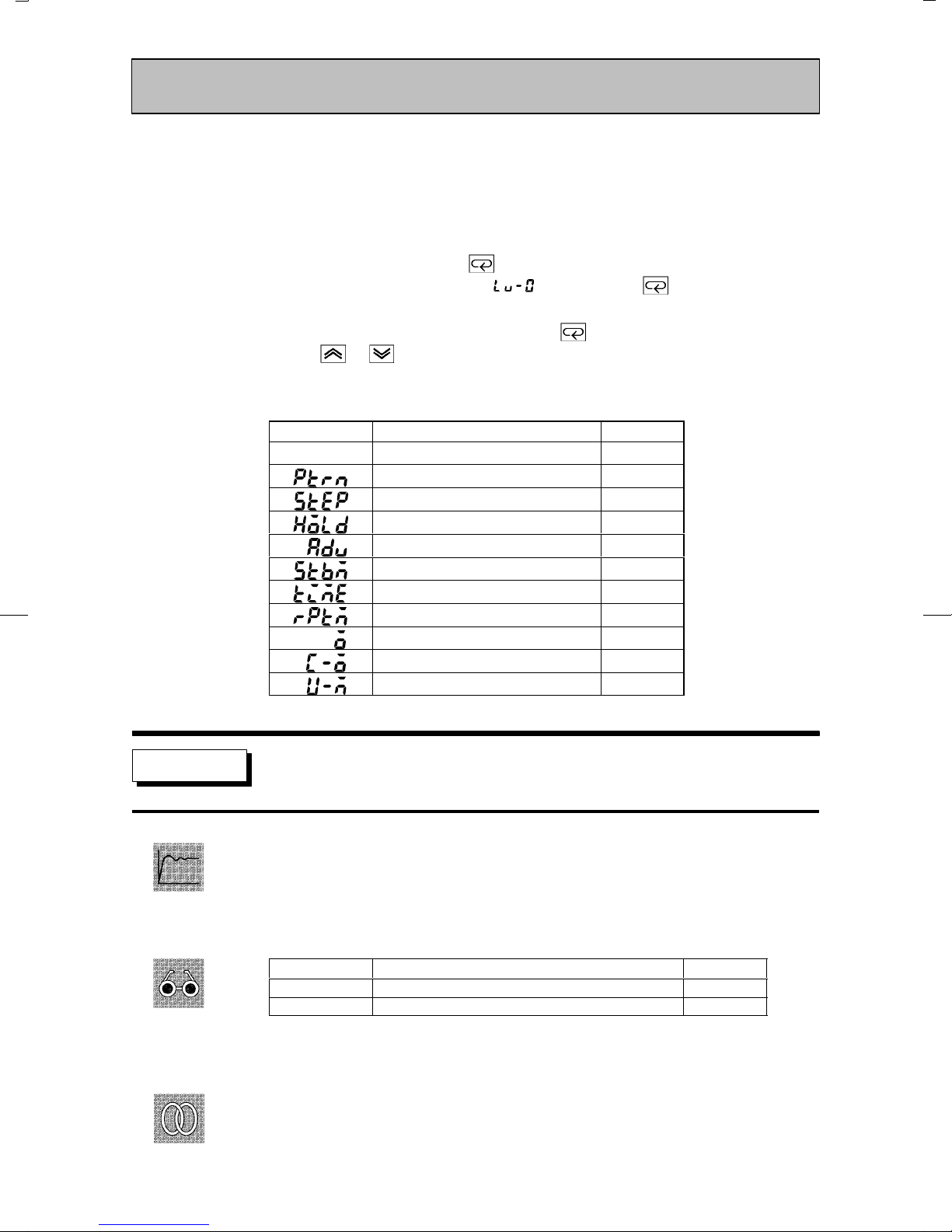
CHAPTER 5 PARAMETERS
Level 0 Mode
Ă• The parameters in this mode can be used only when the security" parameter (proĆ
tect mode) is set to 0" to 5". Only the PV/Present SP" parameter can be used when
the security" parameter is set to 6".
Ă• The parameters in this mode comprise step operation parameters and parameters
required for monitoring program operating states.
Ă• To select this mode, press the key for 1 second minimum. The display changes
to the menu display. If you select [ ] then press the key for 1 second miniĆ
mum, the controller enters the level 0 mode.
Ă• To select parameters in this mode, press the key. To change parameter settings,
use the or keys.
Ă• The following table shows the parameters supported in the level 0 mode and the page
where the parameter is described.
Function
Symbol Parameter Name
PV/Present SP 5-6
Pattern No. 5-7
Step No. monitor 5-7
Hold 5-8
Advance 5-8
Standby time monitor 5-9
Pattern elapsing time 5-9
Pattern execution count monitor 5-9
MV monitor (heat) 5-10
MV monitor (cool) 5-10
V alve opening monitor 5-10
Page
PV/Present SP
Ă• The process value is displayed on the No.1 display, and the Present SP is displayed
on the No.2 display.
Ă• The decimal point position is dependent on the selected sensor during temperatures
input and on the results of scaling during analog input.
Process Value
Monitor
Present SP
Ă• During temperature input, the range of the currently selected sensor is taken as the
PV monitor range.
ĂRelated parameters
Input type" Scaling upper limit" Scaling lower limit" Decimal point" (setup mode)
Set point upper limit" Set point lower limit" (expansion mode)
See
5–6
Monitor Range
Scaling lower limit -10%FS to scaling upper limit +10%FS
Set point lower limit to set point upper limit
Unit
EU
EU
Page 97

Function
Setting
See
Level 0 Mode
Pattern No.
Ă• This parameter can be set only when the controller is reset.
Ă• Displays the execution pattern during program operation, and the set pattern after
the controller is reset.
Ă• This parameter can also be used in the program mode.
Setting Range Unit Default
0 to 7 None 0
ĂRelated description
3.5 Setting Patterns (page 3Ć14)
ĂRelated parameters
All parameters in the program mode
Function
Monitor
See
Step No. monitor
Ă• Monitors the current step No. (This parameter is reset to 0" when the controller is
reset.)
Monitor Range
0 to Number of steps-1 None
ĂRelated description
4.4 Program Operation (page 4Ć13)
ĂRelated parameters
Hold" Advance" (level 0 mode)
Unit
5–7
Page 98

CHAPTER 5 PARAMETERS
Level 0 Mode
Hold
Ă• This parameter can only be used for monitoring when the controller is reset.
Ă• Pauses (holds) or cancels program operation.
Function
Ă• When the event input to which Hold/Hold cancel" is assigned is ON, " (Hold) is
displayed, and when : OFF" (Hold cancel) is displayed.
Ă• In addition to the setting of this parameter, hold is canceled by the following condiĆ
tions:
Setting
See
Function
Example
of use
Setting Range
OFF : Hold cancel / ON: Hold
Default
ĂRelated description
4.4 Program Operation (page 4Ć13)
4.8 How to Use Event Input (page 4Ć21)
ĂRelated parameters
Event input assignment 1 to 4" (option mode)
Advance
Ă• This parameter can only be used for monitoring when the controller is reset.
Ă• Forcibly advances program operation by one step.
Ă• When the event input to which Hold/Hold cancel" is assigned is ON, " (Advance)
is displayed.
Ă• Selecting this parameter, it is set to : OFF".
Ă• When : ON" is selected, program operation is advanced by one step.
Ă• After program exection is completed, the setting automatically returns to ".
Ă• Hold is also continued after the program step is advanced when the program is
executed in a hold state.
ĂRelated description
4.4 Program Operation (page 4Ć13)
4.8 How to Use Event Input (page 4Ć21)
See
ĂRelated parameters
Event input assignment 1 to 4" (option mode)
5–8
Page 99

Level 0 Mode
Function
Monitor
See
Function
Standby time monitor
Conditions of Use
The controller must be in a standby state.
Ă• Displays the remaining standby time. (This time is not displayed when the controller
is reset.)
Monitor Range
0.00 to 99.59 Hour, minute
Unit
ĂRelated description
4.7 Setting Running Conditions (page 4Ć19)
ĂRelated parameter
Standby time" (level 2 mode)
Pattern elapsing time
Ă• Displays the time that has elapsed since the start of the pattern. When a pattern is
repeatedly executed or all patterns are executed, the time counting restarts at the top
of each pattern.
Monitor
Function
Monitor
See
Monitor Range
0.00 to 99.59 Program time unit
Unit
When the time exceeds 99.59", 99.59" blinks on the display.
Pattern execution count monitor
Ă• Displays the number of times that the current pattern has been executed. 0" is disĆ
played when the controller is reset or when the controller is in a standby state.
Monitor Range
0 to pattern execution count Times
ĂRelated parameter
Pattern execution count" (program mode)
Unit
5–9
Page 100

CHAPTER 5 PARAMETERS
Level 0 Mode
Function
Monitor
MV monitor (heat)
Conditions of Use
The control must be standard control or
heating and cooling control.
MV monitor (cool)
Ă• This parameter cannot be set.
Ă• Monitors the manipulated variable on the heating or cooling side.
Ă• The manipulated variable in a standard control system is monitored in the MV monĆ
itor (heat)" parameter.
Ă• The MV monitor (cool)" parameter can be used only during heating and cooling conĆ
trol.
Ă• MV monitor (heat)
Control
Standard -5.0 to 105.0 %
Heating and cooling 0.0 to 105.0 %
Monitor Range
Ă• MV monitor (cool)
Control
Heating and cooling 0.0 to 105.0 %
Monitor Range
Unit
Unit
Model
Function
Monitor
See
E5AKĆTAA2
Valve opening monitor
Conditions of Use
The control must be position-proportional
control.
Ă• Monitors the valve opening during positionĆproportional control.
Moniter Range
-10.0 to +1 10.0 %
Unit
ĆĆĆĆ" is displayed when a potentiometer is not connected.
ĂRelated description
4.1 Selecting the Control Method/PositionĆproportional control (page 4Ć3)
E5AKĆTPRR2
Model
5–10
 Loading...