

Omron E5CD-**2**M-004 Series, E5CD-**2**M-002 Series, E5ED-**4**M-004 Series, E5ED-**4**M-022 Series, E5ED-**4**M-008 Series Connection Manual
...Page 1
Machine Automation Controller NJ-series
General-purpose Serial
Connection Guide
(RS-485 CompoWay/F)
OMRON Corporation
Digital Temprature Controller
(E5□D / E5□C / E5□C-T)
P520-E1-02
Page 2

About Intellectual Property Rights and Trademarks
Microsoft product screen shots reprinted with permission from Microsoft Corporation.
Windows is a registered trademark of Microsoft Corporation in the USA and other countries.
EtherCAT® is registered trademark and patented technology, licensed by Beckhoff Automation
GmbH, Germany.
Sysmac is a trademark or registered trademark of OMRON Corporation in Japan and other
countries for OMRON factory automation products.
Company names and product names in this guide are the t rademarks or registered trademarks
of their respective companies.
Page 3

Table of Contents
1. Related Manuals ........................................................................................ 1
2. Terms and Definitions ............................................................................... 1
3. Precautions ................................................................................................ 2
4. Overview .................................................................................................... 3
5. Applicable Devices and Device Configuration ....................................... 4
Applicable Devices ............................................................................. 4 5.1.
Device Configuration .......................................................................... 6 5.2.
6. Serial Communications Settings ............................................................. 8
Parameters ........................................................................................ 8 6.1.
Cable Wiring ...................................................................................... 9 6.2.
7. Serial Communications Connection Procedure ................................... 10
Work Flow ........................................................................................ 10 7.1.
Digital Temperature Controller Setup ................................................ 11 7.2.
Controller Setup ............................................................................... 15 7.3.
Serial Communication Status Check ................................................ 30 7.4.
8. Initialization Method ................................................................................ 32
Initializing a Controller ...................................................................... 32 8.1.
Initializing a Digital Temperature Controller ...................................... 33 8.2.
9. Program .................................................................................................... 34
Overview .......................................................................................... 34 9.1.
Destination Device Command .......................................................... 40 9.2.
Error Detection Processing .............................................................. 43 9.3.
Variables .......................................................................................... 44 9.4.
ST Program ...................................................................................... 46 9.5.
Timing Charts ................................................................................... 51 9.6.
Error Processing .............................................................................. 52 9.7.
10. Revision History .................................................................................. 56
Page 4

1.Related Manuals
1
for NJ-series CPU Unit
1. Related Manuals
To ensure system safety, make sure to always read and follow the information provided in all
Safety Precautions and Precautions for Saf e Use in the manuals for each device which is
used in the system.
The table below lists the manuals pertaining to t his guide.
Cat. No. Model Manual name
W500 NJ501-□□□□
NJ301-□□□□
NJ101-□□□□
W501 NJ501-□□□□
NJ301-□□□□
NJ101-□□□□
W502 NJ501-□□□□
NJ301-□□□□
NJ101-□□□□
W504 SYSMAC-SE2□□□ Sysmac Studio Version 1 Operation Manual
W494 CJ1W-SCU□2 CJ-series
NJ-series
CPU Unit
Hardware User's Manual
NJ/NX-series
CPU Unit
Software User's Manual
NJ/NX-series
Instructions Reference Manual
Serial Communications Units
Operation Manual
H225 E5□D Digital Temperature Controllers
Communications Manual
H224 E5□D Digital Temperature Controllers User’s Manual
H175 E5□C Digital Temperature Controllers
Communications Manual
H174 E5□C Digital Temperature Controllers User’s Manual
H186 E5□C-T Digital Temperature Controllers
Programmable Type
Communications Manual
H185 E5□C-T Digital Temperature Controllers
Programmable Type User’s Manual
2. Terms and Definitions
Term Explanation and Definition
Serial Gateway
mode
This is a function of PLC that performs serial communic ations by
automatically converting a message (command data) to a specified
protocol (CompoWay/F, Modbus-RTU, or Modbus-ASCII), depending on
the type of message.
Page 5
3.Precautions
2
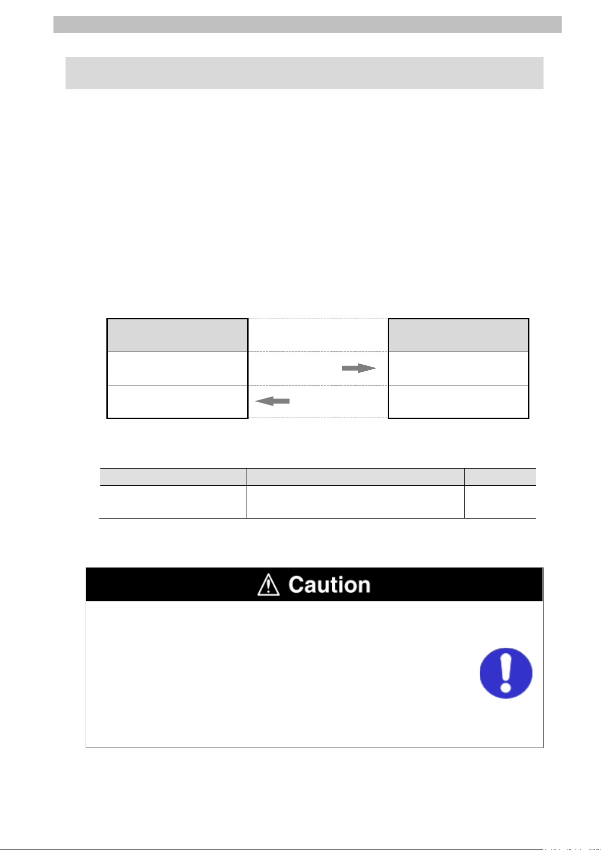
Indicates a potentially hazardous situation whi ch, if not avoided,
damage.
Precautions for Correct Use
Additional Information
Symbol
3. Precautions
(1) Understand the specifications of devices which are used in the system. Allow some
margin for ratings and performance. Provide saf ety measures, such as installing a safety
circuit, in order to ensure safety and minimize the risk of abnormal occurrence.
(2) To ensure system safety, make sure to always read and follow the information provided in
all Safety Precautions and Precautions for Safe Use in the manuals for each device
which is used in the system.
(3) The user is encouraged to confirm the standards and regulations that the system must
conform to.
(4) It is prohibited to copy, to reproduce, and to distribute a part or the whole of this guide
without the permission of OMRON Corporation.
(5) The information contained in this guide is current as of March 2018. It is subject to
change for improvement without notice.
The following notations are used in this guide.
may result in minor or moderate injury, or may result in serious
injury or death. Additionally there may be significant property
Indicates a potentially hazardous situation whi ch, if not avoided,
may result in minor or moderate injury or property damage.
Precautions on what to do and what not to do to ensure proper operation and performance.
Additional information to read as required.
This information is provided to increase unders tanding or make operation easier.
The filled circle symbol indicates operations that you must do.
The specific operation is shown in the circl e and explained in the text.
This example shows a general precaution for something t hat you must do.
Page 6
4.Overview
3
Name
File name
Version
Command data
Response data
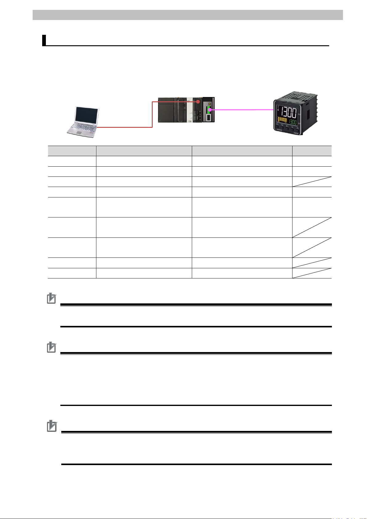
4. Overview
This guide describes procedures for connecting a Digital Temperature Controller (E5□D,
E5□C or E5□C-T) to an NJ-series Machine Automation Controller + Serial Communications
Unit (hereinafter referred to as the "Controller") via serial communications, both produced by
OMRON Corporation (hereinafter referred to as "OM RO N"), and for checking their
communication status.
Refer to Section 6. Serial Communications Set tings and Section 7. Serial Communications
Connection Procedure to understand setting methods and key points to send or receive a
message via serial communications.
The program in the prepared Sysmac Studio project file is used to check the serial connection
by sending or receiving a message of ''Read Controller Attributes'' to/from the Digital
Temperature Controller.
■The send/receive messages of "Read Controller Attributes''
Controller
Sending command data Executing the command
Receiving response data
and storing in memory
Prepare the Sysmac Studio project file with a lat est version beforehand.
To obtain the Sysmac Studio project file, contact your OMRON representative.
Sysmac Studio project file
(extension: csm2)
Hereinafter, the Sysmac Studio project file is referred to as “the project file".
This guide aims to explain wiring methods and communications settings
necessary to connect corresponding devic es and provides the setting
procedures. The program used in this guide is not designed to be cons tantly
used at a site but is designed to check if the c onnection is properly established.
Both functionalities and performances are therefore not fully considered for the
program.
When you actually construct a system, please us e the wiring methods,
communications settings and setting procedures described in this guide as a
reference, and design a program according to you r appl ication needs.
Serial communications
(RS-485)
Returni ng response data
P520_NJ_CWF485_OMRON_E5CD_V100.
csm2
Digital Temperature
Controller
Ver.1.00
Page 7

4
5. Applicable Devices and Device Configuration
OMRON
NJ-series CPU Unit
NJ501-□□□□
NJ101-□□□□
OMRON
Serial Communications Unit
CJ1W-SCU□2
E5CD-□□2□□M-002
E5EC-T□□4□SM-022
5.Applicable Devices and Device Configuration
Applicable Devices 5.1.
The applicable devices are as follows:
Manufacturer Name Model
NJ301-□□□□
OMRON Digital Temperature Controller
E5CD-□□2□□M-004
E5ED-□□4□□M-004
E5ED-□□4□□M-008
E5ED-□□4□□M-022
E5CC-□□□□□M-002
E5CC-□□□□□M-003
E5CC-□□□□□M-004
E5AC-□□□□SM-004
E5AC-□□□□SM-008
E5AC-□□□□SM-009
E5AC-□□□□SM-012
E5AC-□□□□SM-014
E5EC-□□□□□M-004
E5EC-□□□□□M-008
E5EC-□□□□□M-009
E5EC-□□□□□M-012
E5EC-□□□□□M-014
E5DC-□□□□□M-002
E5DC-□□□□□M-015
E5GC-□□□□□M-015
E5CC-T□□3□SM-002
E5CC-T□□3□SM-003
E5CC-T□□3□SM-004
E5AC-T□□4□SM-004
E5AC-T□□4□SM-008
E5AC-T□□4□SM-020
E5AC-T□□4□SM-022
E5EC-T□□4□SM-004
E5EC-T□□4□SM-008
E5EC-T□□4□SM-020
Page 8

5.Applicable Devices and Device Configuration
5
Precautions for Correct Use
Additional Information
In this guide, the devices with models and versions listed in 5.2. Device Configuration are
used as examples of applicable devices to des cribe the procedures for connecting the
devices and checking their connection.
You cannot use devices with versions lower than the versions list ed i n 5.2.
To use the above devices with models not listed in 5.2. or versions higher than those listed in
5.2., check the differences in the specifications by referring to t he manuals before operating
the devices.
This guide describes the procedures for establi shing the network connection.
It does not provide information on operation, installation, wiring method, device functional it y,
or device operation, which is not related to the connection procedures.
Refer to the manuals or contact your OMRON representative.
Page 9
5.Applicable Devices and Device Configuration
6
OMRON
Serial Communications Unit
CJ1W-SCU42
Ver.2.0
OMRON
Sysmac Studio
SYSMAC-SE2□□□
Ver.1.21
-
Serial cable (RS-485)
-
Precautions for Correct Use
Precautions for Correct Use
Precautions for Correct Use
Personal computer
NJ501-1500+
CJ1W-SCU42
Serial cable
E5CD-RX2A6M-002
USB cable
Device Configuration 5.2.
The hardware components to reproduce the connect i on procedures in this guide are as
follows:
(Sysmac Studio installed,
OS: Windows 7)
Manufacturer Name Model Version
OMRON NJ-series CPU Unit NJ501-1500 Ver.1.16
OMRON Power Supply Unit NJ-PA3001
(RS-485)
OMRON Sysmac Studio project file P520_NJ_CWF485_OMRON_E
Ver.1.00
5CD_V100.csm2
- Personal computer
-
(OS: Windows 7)
- USB cable
-
(USB 2.0 type B connector)
OMRON Digital Temperature Controller E5CD-RX2A6M-002
Prepare the project file with a latest version beforeh and.
To obtain the project file, contact your OMRON representative.
Update Sysmac Studio to the version speci fied in this Clause 5.2. or to a higher version.
If you use a version higher than the one specified, the procedures and related screenshots
described in Section 7. and the subsequent sections may not be applicable.
In that case, use the equivalent procedures described in this guide by referring to the Sysmac
Studio Version 1 Operation Manual (Cat. No. W504).
Turn ON the terminating resistance switch on the Serial Communications Unit and connect
120 Ω (1/2 W) terminating resistance to the terminals of the Digital Temperature Controller at
either end of the RS-422A/485 transmission path.
Page 10

7
Additional Information
Operation Manual (Cat. No. W504).
For information on the serial cable (RS-485), refer to 3-3 RS-232C and RS-422A/485 Wiring
of the CJ-series Serial Communications Units Operation Manual for NJ-series CPU Unit (Cat.
No. W494).
Additional Information
The system configuration in this guide uses USB for the connection between the personal
computer and the Controller. For information on how to install the USB driver, refer to A-1
Driver Installation for Direct USB Cable Connection of the Sysmac Studio Version 1
5.Applicable Devices and Device Configuration
Page 11

6.Serial Communications Settings
8
(transmission character)
Baud rate
9,600 bps (default)
9,600 bps (default)
6. Serial Communications Settings
This section describes the parameters and cable wiri ng, which are set up in this guide.
Parameters 6.1.
The following parameters are required to connect t he Controller and the Digital Temperature
Controller via serial communications .
Setting item
Device name J01 Unit No. 0 Communications Unit No.
(slave address)
Serial communications port
(connection)
Terminating resistance Terminating resistance ON
2-wire or 4-wire 2-wire (WIRE: 2) 2-wire (fixed)
Serial communications mode Serial Gateway Data length
(Serial Communications Unit)
- 1 (default)
Port 1 (RS-422A/485) -
(TERM: ON)
7 bits (default) 7 bi ts (default)
Controller
Digital Temperature
Controller
-
Stop bits 2 bits (default) 2 bi ts (default)
Parity (parity bit) Even (default) Even (default)
Communications method - CompoWay/F (default)
Send data wait time - 20 ms (default)
Precautions for Correct Use
The connection procedure described in this gui de assumes that the following Serial
Communications Unit, port and setting values are used.
Model: CJ1W-SCU42
Serial communications port: Port 1
Unit No.: 0
Device name: J01
If you connect devices under different conditions, refer to Section 9. Program and create a
program by changing the variable names and sett i ng values .
Page 12
6.Serial Communications Settings
9
Pin No.
Signal name
Input/Output
5 (See note 2.)
FG
Shield
-
SDB+
4
Additional Information
refer to their respective manuals.
Ter minating r esistance
Cable Wiring 6.2.
Refer to Section 3 Installation and Wiring of the CJ-series Serial Communications Units
Operation Manual for NJ-series CPU Unit (Cat. No. W494) for details on cable wiring.
Check the connector configurations and pin assignments before wiring.
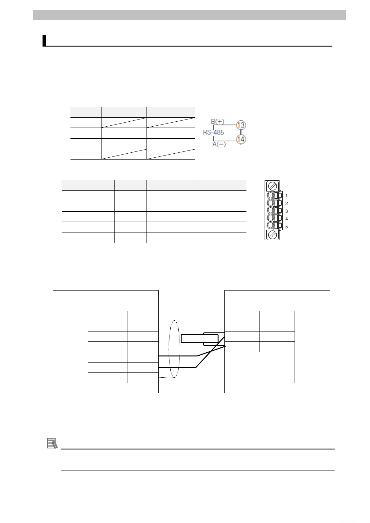
■Connector configuration and pin assignment
Digital Temperature Controller (E5CD) applicable connector: Termi nal block
1-12
13 B(+) Input/Output
14 A(-) Input/Output
15-18
Serial Communications Unit (CJ1W-SCU42) applicable connector: Terminal block
Pin No. Symbol Signal name Input/Output
1 (See note 1.) RDA Receive data - Input
2 (See note 1.) RDB Receive data + Input
3 (See note 1.) SDA Send data - Output
4 (See note 1.) SDB Send data + Output
Note 1: For 2-wire connection, use either pins 1 and 2 or pins 3 and 4.
2: Pin 5 (Shield) is connected to the GR terminal on the Power Supply Unit though the
Serial Communications Unit. The cable shield can thus be grounded if you ground the
GR terminal of the Power Supply Unit.
■Cable and pin assignment
Serial Communications
Digital Temperature Controller
Unit (CJ1W-SCU42)
RS-422A/
485
interface
Signal
name
Pin No. Terminal
No.
RDA- 1 13 B(+)
RDB+ 2 14 A(-)
SDA- 3
FG 5
Terminal block Terminal block
Connect 120 Ω (1/2 W) terminating resistance
between B(+) and A(-) of the Digital Temperature
Controller that is connected at the end of the
network.
(E5CD)
Signal
name
RS-485
interface
For information on the connector configurations and pin assignments of the other models,
Page 13

7.Serial Communications Connection Procedure
10
Setup
Set up the Digital Temperature Controller.
Set parameters for the Digital Temperature
Controller.
7.3. Controller Setup
Set up the Controller.
Set the hardware switches on the Serial
Communications Unit and connect the cables .
Importing the Project File
Start Sysmac Studio and import the project f i le.
Check the parameters of the Serial
on the project data, and build the project programs.
Go online with Sysmac Studio and transfer t he
Transfer the setting data of the Serial
Communications Unit.
Check
Start the send/receive processing and confirm t hat
Check that correct data is written to the variables of
the Controller in Sysmac Studio.
7. Serial Communications Connection Procedure
This section describes the procedures for connecting the Controller to the Digital Temperature
Controller via serial communications . The procedures f or setting up the Controller and the
Digital Temperature Controller in this guide are based on the f actory default settings.
For the initialization, refer to Section 8. Initialization Method.
Work Flow 7.1.
Take the following steps to connect the Controller and the Digital Temperature Controller via
serial communications and to send or receive a message.
7.2. Digital Temperature Controller
↓
7.2.1. Parameter Settings
↓
↓
7.3.1. Hardware Settings
↓
7.3.2. Starting Sysmac Studio and
↓
7.3.3. Checking the Parameters and
Building Programs
↓
7.3.4. Going Online and Transferring
the Project Data
Communications Unit, execute the program check
project data to the Controller.
↓
7.3.5. Transferring the Unit Settings
↓
7.4. Serial Communication Status
↓
7.4.1. Checking Received Data
serial communications performs normall y.
Page 14
7.Serial Communications Connection Procedure
11
1
manuals.
2
(Down) Key
3
4
Serial cable
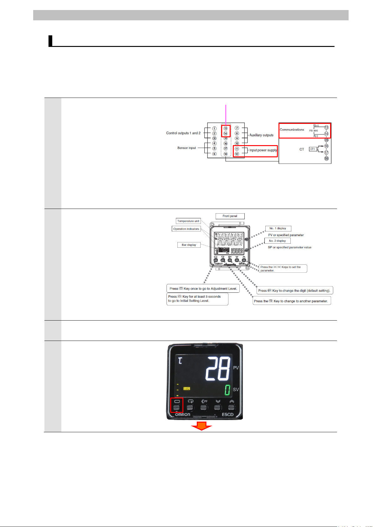
Digital Temperature Controller Setup 7.2.
Set up the Digital Temperature Controller.
7.2.1. Parameter Settings
Set parameters for the Digital T emperature Controller.
Connect the power supply and a
serial cable to the terminal block
located on the back of Digital
Temperature Controller.
*Only the parameters in
Communications Setting Level
are described in this guide.
If you use the parameters in
Adjustment Level that is
specific to each of the models,
refer to their respective
(RS-485)
Check the positions of each of
the keys, No.1 and No. 2
displays and Operation
indicators.
In this guide, the keys are
described as follows:
L (Level) Key
M (Mode) Key
U (Up) Key
D
Turn ON Digital Temperature
Controller.
The current temperature is
displayed on No. 1 display once
Digital Temperature Controller is
turned ON. (Operation Level)
Press the L (Level) Key for at
least 3 seconds.
L (Level) Key for at least 3 seconds
Page 15
7.Serial Communications Connection Procedure
12
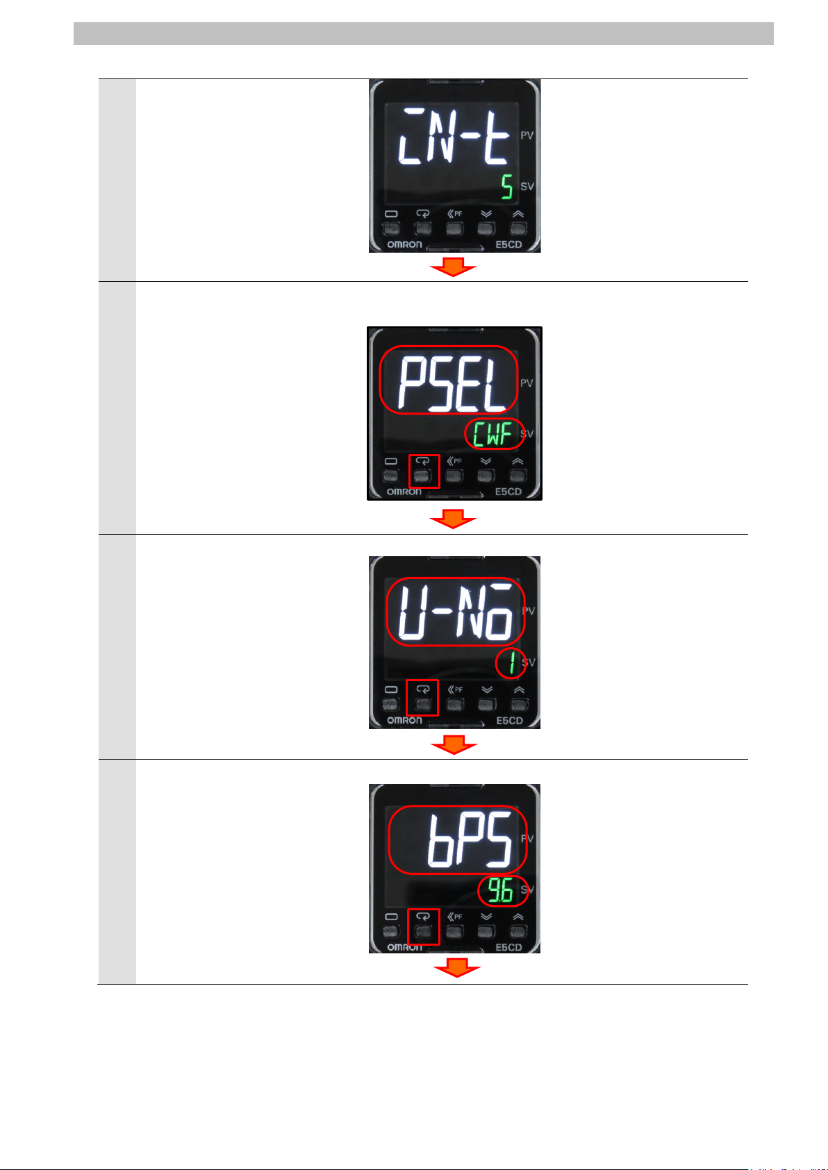
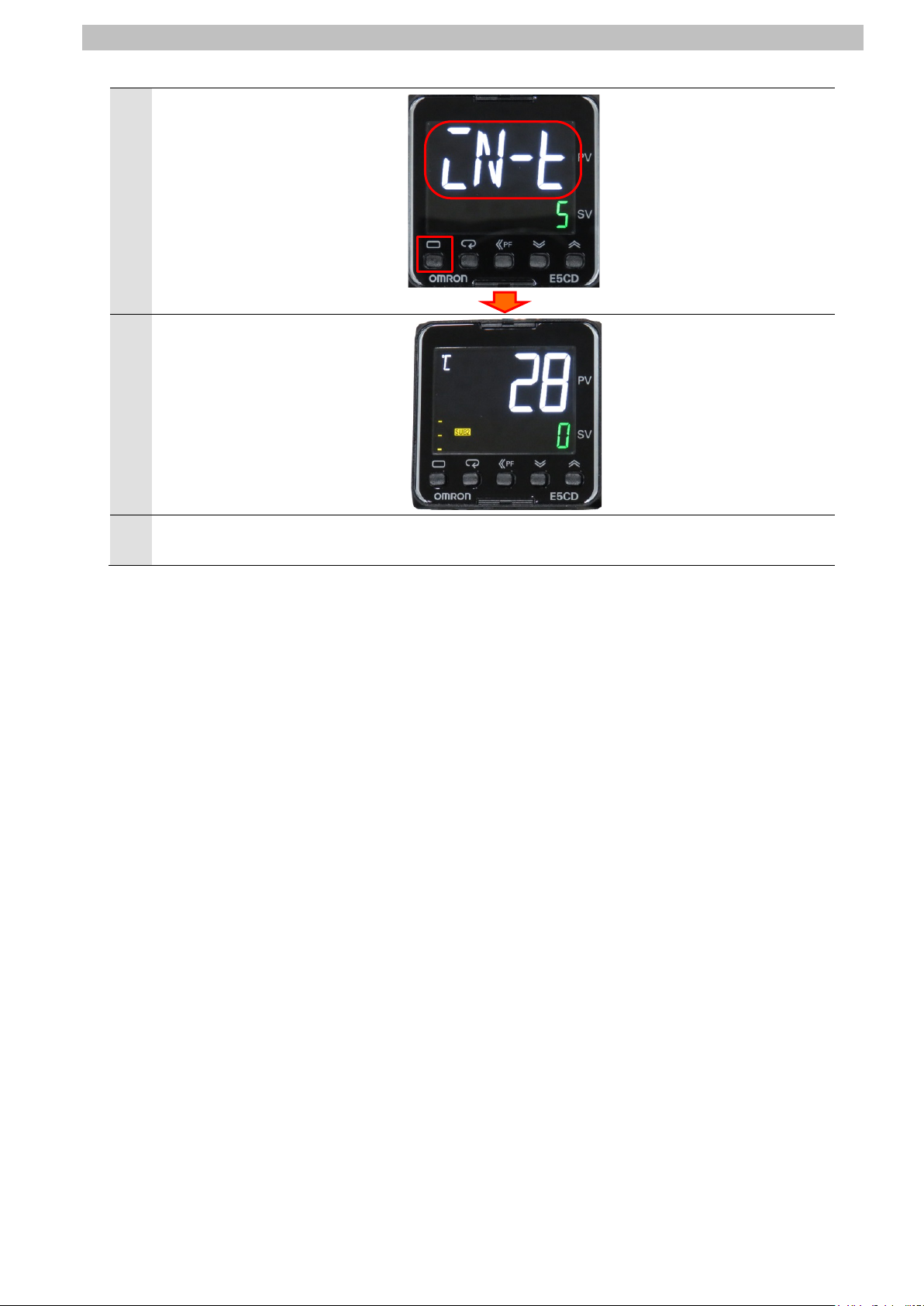
"in-t" (Initial Setting Level) is
5
displayed on No. 1 display.
Press the L (Level) Key again
for less than 1 second.
The display changes to
6
Communications Setting Level.
"psel" (Protocol Setting) and
"cwf" (CompoWay/F) are
displayed on No. 1 and No. 2
displays, respectively.
*If the setting value is different,
press the U (Up) or D (Down)
Key to change the parameter.
Press the M (Mode) Key.
"u-no" (Communications Unit
7
No.) is displayed.
Check that Communications
Unit No. is 1.
*If the setting value is different,
change it in the same way as
step 6.
Press the M (Mode) Key.
"bps" (Communications Baud
8
Rate) is displayed.
Check that Communications
Baud Rate is 9.6 kbps.
*If the setting value is different,
change it in the same way as
step 6.
Press the M (Mode) Key.
L (Level) Key
< Setting value>
CWF / Mod
(default: CWF)
CWF: CompoWay/F
Mod: Modbus-RTU
M (Mode) Key
<Setting value>
0 to 99 (default: 1)
M (Mode) Key
<Setting value>
9.6, 19.2, 38.4 or
57.6 kbps
(default: 9.6)
M (Mode) Key
Page 16
7.Serial Communications Connection Procedure
13
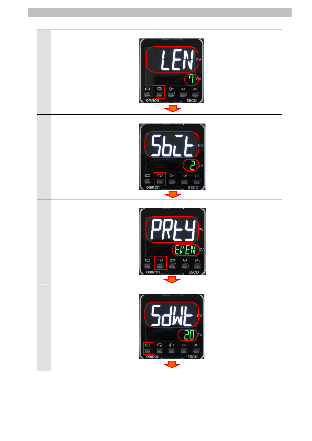
"len" (Communications Data
9
Length) is displayed.
Check that Communications
Data Length is 7 bits.
*If the setting value is different,
change it in the same way as
step 6.
Press the M (Mode) Key.
"sbit" (Communications Stop
10
Bits) is displayed.
Check that Communications
Stop Bits is 2 bits.
*If the setting value is different,
change it in the same way as
step 6.
Press the M (Mode) Key.
"prty" (Communications Parity)
11
is displayed.
Check that Communications
Parity is EVEN.
*If the setting value is different,
change it in the same way as
step 6.
Press the M (Mode) Key.
"sdwt" (Send Data Wait Time) is
12
displayed.
Check that Send Data Wait Time
is 20.
*If the setting value is different,
change it in the same way as
step 6.
Press the L (Level) Key for less
than 1 second.
<Setting value>
7 or 8 bits (default: 7)
M (Mode) Key
<Setting value>
1 or 2 bits (default: 2)
M (Mode) Key
<Setting value>
NONE, EVEN or ODD
(default: EVEN)
M (Mode) Key
<Setting value>
0 to 99 ms (default: 20)
L (Level) Key.
Page 17
7.Serial Communications Connection Procedure
14
15
"in-t" ((Initial Setting Level) is
13
displayed.
Press the L (Level) Key for at
least 1 second.
The display returns to Operation
14
Level as shown in step 4.
Turn OFF Digital Temperature
Controller.
L (Level) Key for at least 1 second
Page 18
7.Serial Communications Connection Procedure
15
be applicable.
2
3
4
5
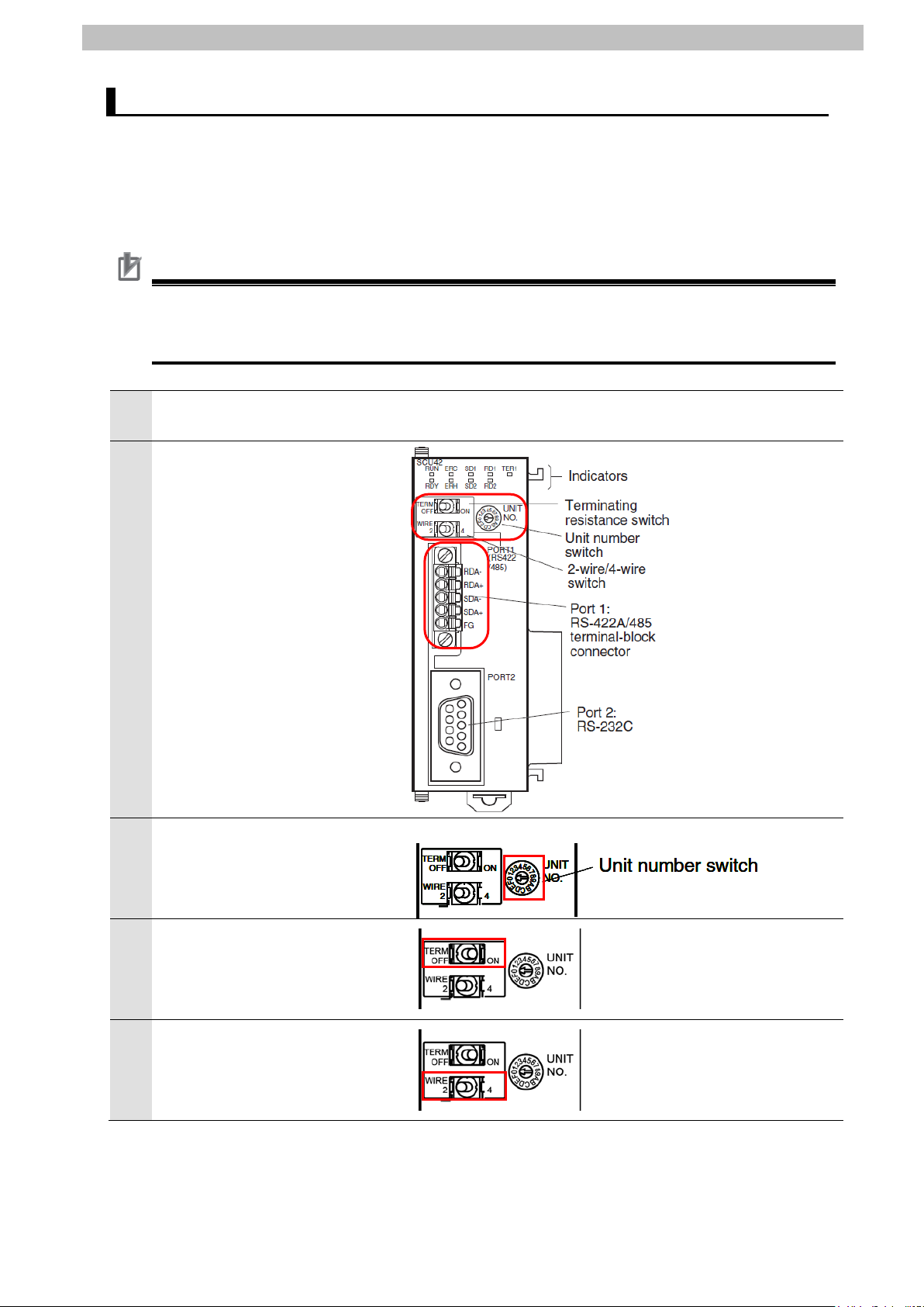
・TERM
・WIRE (2-wire or 4-wire switch)
2: 2-wire, 4: 4-wire
Controller Setup 7.3.
Set up the Controller.
7.3.1. Hardware Settings
Set the hardware switches on the Serial Communications Unit and connect the cables.
Precautions for Correct Use
Make sure that the power supply is OFF when you set up.
If it is ON, the settings described in the following steps and subsequent proc edures may not
Make sure that Controller is
1
powered OFF.
Check the positions of the
hardware switches and Port 1
on the front panel of Serial
Communications Unit by
referring to the figure on the
right.
Set Unit number switch to 0.
*The unit number is set to 0 as
the factory default setting.
Set Terminating resistance
ON/OFF switch to ON.
(Terminating resistance ON)
Set 2-wire or 4-wire switch to 2.
(2-wire)
(Terminating resistance ON/OFF switch)
OFF: Terminating resistance OFF
ON: Terminating resistance ON
Page 19

7.Serial Communications Connection Procedure
16
Serial cable
(RS-485)
Serial Communications Unit
USB
Cable
Controller
End Cover
Power Supply Unit
CPU Unit
Personal
Connect Serial Communications
6
Unit to Controller as shown on
the right.
Connect Digital T emperature
Controller and Port 1 on Serial
Communications Unit with the
serial cable.
Connect Personal computer and
Controller with a USB cable.
computer
Page 20

7.Serial Communications Connection Procedure
17
1
Sysmac Studio.
2
7.3.2. Starting Sysmac Studio and Importing the Project File
Start Sysmac Studio and import the project f i le.
Install Sysmac Studio and the USB driver on your pers onal computer beforehand.
Start Sysmac Studio.
*If the User Account Control
Dialog Box is displayed at start,
make a selection to start
Click Import.
The Import file Dialog Box is
3
displayed.
Select P520_NJ_CWF485_
OMRON_E5CD_V100.csm2
and click Open.
*Obtain the project file from
OMRON.
Page 21

18
The P520_NJ_CWF485_
Controller
Toolbox
Edit Pane
Multiview
Output T ab
Build T ab
4
OMRON_E5CD_V100 project is
displayed.
The following panes are
displayed in this window.
Left: Multiview Explorer
Top right: T oolbox
Bottom right: Controller Status Pane
Top middle: Edit Pane
The following tabs are displayed
in the bottom middle of this
window.
Output T ab Page
Build T ab Page
7.Serial Communications Connection Procedure
Explorer
Page
Page
Status
Pane
Page 22

7.Serial Communications Connection Procedure
19
1
2
Settings.
3
7.3.3. Checking the Parameters and Building Programs
Check the parameters of the Serial Communic ations Unit, exec ute the program chec k on the
project data, and build the project programs.
Double-click CPU/Expansion
Racks under Configurations
and Setup in the Multiview
Explorer.
The CPU/Expansion Racks Tab
Page is displayed in the Edit
Pane.
Select Serial Communications
Unit as shown on the right.
The setting values of
CJ1W-SCU42 are displayed.
Check that the device name is
J01 and that the unit No. is 0.
*If the setting values are
different from the above,
change the values.
Click Edit Special Unit
The 0 [Unit 0] : CJ1W-SCU42
(J01) Tab Page is displayed.
Select Port1: Serial Gateway
Settings from the pull-down list
of Parameter group to show.
Page 23

20
Parameter group to show is set
Apply.
5
6
4
to Port1: Serial Gateway
Settings.
The setting items of Port1: Serial
Gateway Settings are shown.
Check that Port1: Port settings
is set to User settings and that
the other settings are the same
as those listed in 6.1.
Parameters.
*If the setting values are
different, select the values from
the pull-down list. After
changing the values, click
7.Serial Communications Connection Procedure
Double-click I/O Map under
Configurations and Setup in
the Multiview Explorer.
The I/O Map Tab Page i s
displayed, and then the
parameters of Serial
Communications Unit are listed.
Check that the variable names
in the Variable Column start with
J01 and that "Global Variables"
is set for each of them in the
Variable Type Column.
*If the settings are different from
the above, right-click
CJ1W-SCU42 and select
Create Device Variable.
Page 24

21
Double-click Task Settings
8
9
10
12
13
7
under Configurations and
Setup in the Multiview Explorer.
The Task Settings Tab Page is
displayed in the Edit Pane.
Click the Program Assignment
Settings Button. Check that
Program0 is set in the Primary
Task Field and that Run is set as
the initial status.
Select Check All Programs
from the Project Menu.
The Build Tab Page is displayed.
Check that "0 Errors" and "0
Warnings" are displayed.
7.Serial Communications Connection Procedure
Select Rebuild Controller from
11
the Project Menu.
A confirmation dialog box is
displayed. Check the contents
and click Yes.
Check that "0 Errors" and "0
Warnings" are displayed on the
Build Tab Page.
Page 25

7.Serial Communications Connection Procedure
22
Unit.
1
Temperature Controller.
2
3
4
7.3.4. Going Online and Transferring the Project Data
Go online with Sysmac Studio and transfer t he proje ct data to the Controller.
Always confirm safety at the destination node before you transfer a user
program, configuration data, setup data, devi ce variables, or values in memory
used for CJ-series Units from Sysmac Studio. The devices or machines may
perform unexpected operation regardless of t he operating mode of the CPU
Always confirm safety before you reset the Controll er or any components.
Turn ON Controller and Digital
Select Change Device from the
Controller Menu.
The Change Device Dialog Box
is displayed.
Check that the Device and
Version Fields are set as shown
on the right.
Click Cancel.
*If the settings are different,
select the setting items from
the pull-down list, and click OK.
Select Communications Setup
from the Controller Menu.
Page 26

23
The Communications Setup
6
processing.
Additional Information
8
5
Dialog Box is displayed.
Select Direct connection via
USB in the Connection type
Field.
Click OK.
Select Online from the
Controller Menu.
The dialog box on the right is
displayed, check the contents
and click Yes.
*The contents of the dialog box
vary depending on the status of
Controller. Check the contents
and click on an appropriate
button to proceed with the
7.Serial Communications Connection Procedure
When an online connection is
7
established, a yellow line is
displayed under the toolbar.
For details on the online connections to the Controller, refer to Section 6. Online Connections
to a Controller of the Sysmac Studio Version 1 Operation Manual (Cat. No. W504).
Select Synchronize from the
Controller Menu.
Page 27

7.Serial Communications Connection Procedure
24
10
The Synchronization Dialog Box
9
is displayed.
Check that the data to transfer
(NJ501 shown on the right) is
selected.
Click Transfer To Contro ller.
*After executing "Transfer To
Controller", the Sysmac Studio
data is transferred to
Controller, and the data is
synchronized.
A confirmation dialog box is
displayed. Confirm that there is
no problem, and click Yes.
A screen is displayed stating
"Synchronizing".
A confirmation dialog box is
displayed. Confirm that there is
no problem, and click No.
*Do not return to RUN mode.
Page 28

7.Serial Communications Connection Procedure
25
from step 1.
Precautions for Correct Use
As shown in the figure on the
11
right, the font color that is used
to display the synchronized data
changes to the same color as
the one used to specify
"Synchronized". Check that a
message is displayed stating
"The Synchronization process
successfully finished".
Confirm that there is no
problem, and click Close.
*When the Sysmac Studio
project data coincides with the
Controller data, a message is
displayed stating "The
synchronization process
successfully finished".
*If the synchronization fails,
check the wiring and repeat
Always confirm safety before you reset the Controll er or any components in step 13 and
subsequent steps.
Page 29

26
Select Reset Controller from
13
14
15
12
the Controller Menu.
*”Reset Controller” cannot be
selected when the operating
mode of Controller is RUN
Mode. In this case, select
Mode - PROGRAM Mode from
the Controller Menu to change
to PROGRAM mode, and then
perform this step.
7.Serial Communications Connection Procedure
A confirmation dialog box is
displayed. Check the contents
and click Yes.
A confirmation dialog box is
displayed. Check the contents
and click Yes.
The Controller is reset, and
Sysmac Studio goes offline.
The yellow line under the toolbar
disappears.
Page 30

7.Serial Communications Connection Procedure
27
1
4
5
Settings
7.3.5. Transferring the Unit Settings
Transfer the setting data of the Serial Communications Unit.
Select Online from the
Controller Menu.
When an online connection is
2
established, a yellow line is
displayed under the toolbar.
Select Mode - PROGRAM
3
Mode from the Controller Menu.
A confirmation dialog box is
displayed. Confirm that there is
no problem, and click Yes.
PROGRAM mode is displayed
in the Controller Status Pane.
Double-click CPU/Expansion
6
Racks under Configurations
and Setup in the Multiview
Explorer.
Select Serial Communications
Unit displayed on the CPU Rack
configuration.
Click Edit Special Unit
.
Page 31

28
The 0 [Unit 0] : CJ1W-SCU42
8
Yes
9
10
7
(J01) Tab Page is displayed.
Click Transfer to Controller.
A confirmation dialog box is
displayed. Check the contents
and click Yes.
A dialog box is displayed
indicating that transferring is
being performed. After that, the
dialog box on the right is
displayed. Check the contents
and click
The Port Selection Dialog Box is
displayed.
Select All ports and click OK.
.
7.Serial Communications Connection Procedure
A confirmation dialog box is
displayed. Check the contents
and click OK.
Page 32

29
Select Port1: Serial Gateway
11
Settings from the pull-down list
of Parameter group to show.
Click Compare.
Check that "≠" (mismatch) is
12
not shown within the red oval in
the figure on the right.
7.Serial Communications Connection Procedure
Page 33

7.Serial Communications Connection Procedure
30
change the variable values on a Watch Tab
Precautions for Correct Use
1
2
3
Serial Communication Status Check 7.4.
Start the send/receive processing and confirm that serial communications performs norm al ly.
If you change the variable values on a Watch Tab Page when Sysmac Studio is
online with the CPU Unit, the devices connected to the Controller may operat e
regardless of the operating mode of the CPU Unit.
Always ensure safety before you
Page when Sysmac Studio is online with the CPU Unit.
Check that the serial cable is connected before performing the following procedure.
If not, turn OFF both devices, and then connect the seri al cable.
7.4.1. Checking Received Data
Check that correct data is written to the variables of the Controller in Sysmac Studio.
Select Mode - RUN Mode from
the Controller Menu.
The dialog box on the right is
displayed. Confirm that there is
no problem, and click Yes.
RUN mode is displayed in the
Controller Status Pane.
Page 34

31
Select Watch Tab Page from
5
6
variable.
7
pull-down list.
9
Communications start switch
String data
The number of data bytes
4
the View Menu.
Select the Watch (Project)1
Tab.
Check that the variables shown
on the right are displayed in the
Name Column.
*Click Input Name to add a
7.Serial Communications Connection Procedure
Check that the display format of
Output_recvByteSize is
Decimal.
*If not, select Decimal from the
Click TRUE in the Modify
8
Column for Input_Start.
The online value of Input_Start
changes to True, and the
communications processing
starts.
Check received data on the
Watch Tab Page of Sysmac
Studio.
*The example on the right shows
that the online values of
Output_recvByteSize (the
number of data bytes) and
Output_recvCWFdata (string
data) are 28 bytes and “01 00
00 0503 0000 E5CD-RX2A6
00D9”, respectively.
The response data varies
depending on the device used.
・・・
Response data
01= Node No.
00= Subaddress
00= End code
0503= Command (MRC, SRC)
0000= Response (MRES, SRES)
E5CD-RX2A6 = Receive data (Controller Attributes)
00D9 = Buffer size
Page 35

8.Initialization Method
32
8. Initialization Method
The setting procedures in this guide are based on the f actory default settings.
Some settings may not be applicable unless you use the devices with the factory default
settings.
Initializing a Controller 8.1.
To initialize the settings of a Controller, it is necessary to initialize a Serial Communications
Unit and a CPU Unit. Change the operating mode of the Controller to PROGRAM mode
before the initialization.
8.1.1. Serial Communications Unit
To initialize the settings of a Serial Communications Unit, select the displayed Serial
Communications Unit (CJ1W-SCU42) and click Edit Special Unit Settings on the
CPU/Expansion Racks Tab Page of Sysmac Studio.
Click Return to default and Apply. Then, click Transfer to Controller.
Page 36

8.Initialization Method
33
8.1.2. CPU Unit
To initialize the settings of a CPU Unit, select Clear All Memory from the Controller Menu in
Sysmac Studio.
The Clear All Memory Dialog Box is displayed. Check the contents and click OK.
Initializing a Digital Temperature Controller 8.2.
To initialize the settings of a Digital Tem perature Controll er, refer to Parameter Initialization in
6-8 Advanced Function Setting Level of the Digital Temperature Controllers User's Manual
(Cat. No. H224/H174/H185).
Page 37

9.Program
34
Additional Information
9. Program
This section describes the details on the program in the project file that is used in this guide.
Overview 9.1.
The following explains the specificat i ons and functions of the program that are used to check
the connection between the Digital Temperature Controller (hereinafter referred to as the
"Destination Device") and the Controller (Serial Communications Unit (hereinafter referred t o
as the "SCU")).
This program performs communications via CompoWay/F using the Serial Gateway function
of the SCU, to send/receive the "Read Controller Attributes" command to/from the Destination
Device and detect a normal end or an error end.
A normal end of the send/receive processing means a normal end of communications via
CompoWay/F.
An error end means an error end of communications via Com poWay/F and an error of the
Destination Device (identified in the response data from the Destination Device).
Here, the prefix "10#" (possible to omit) is added to decimal data and the prefix "16#" is added
to hexadecimal data when it is necessary to distinguis h between decimal and hexadecimal
data. (e.g., "1000" or "10#1000" for decimal dat a and "16#03E8" for hexadecimal data)
The prefix "<data type>#" is also added to deci m al or hexadecimal data when specifying a
specific data type. (e.g.,"WORD#16#03E8")
OMRON has confirmed that normal communic ations can be performed using this program
under the conditions of 5.2. Device Configuration. However, we do not guarantee the normal
operation under disturbances such as electri cal noise or device performance variation.
Page 38

9.Program
35
Controller
CPU Unit
SCU
ST program
setting area
Serial Gateway
function
(1) Executes the send command
Command data
Response data
storage area
(2) Sends command data.
(3) Executes the
(4) Receives the response data
9.1.1. Outline of Processing
The following figure shows the data flow from when the Controller (SCU) sends CompoWay/F
command to the Destination Device until the Controller receives response data from the
Destination Device.
(1)The ST program executes the send command instruction (SendCmd instruction) for which
CompoWay/F is specified.
(2)The Controller sends command data of "Read C ontroller Attributes" to the Digital
Temperature Controller using communications via CompoWay/F.
(3)The Digital Temperature Controller executes the command by receiving the command data
from the Controller, and returns response data to the Controller.
(4)The Controller receives the response data f rom the Digital Temperature Controller and
stores in the specified variable.
Controller
RS-485
Digital Temperature
IF …. THEN
……….
ELSE
……….
End_IF
instruction.
SendCmd(…
(SendCmd instruction)
(Specifying CompoWay/F)
Local_cmddata
Command data
Local_recvdata
Response data
(Communications via
CompoWay/F)
command
and returns
response data.
and stores it at the specified
variable in the memory.
Page 39

9.Program
36
Additional Information
(Cat.No. W502).
Name
Function block
Description
Command
Gateway and sends a command to SCU.
9.1.2. SendCmd Instruction and Send/Receive Messages
The following describes the function block for sending a command (hereinafter referred to as
"the SendCmd instruction") and the general operation of sending/receiving a message.
For details on the SendCmd instruction, refer t o Serial Communications Instructions in
Section 2. Instruction Descriptions of the NJ/NX-series Instructions Reference Manual
●SendCmd instruction
Send
SendCmd
●SendCmd instruction argument data
The SendCmd instruction uses a Serial
Page 40

37
[DstNetAdr: Destination network addres s]
= 16#A9
a destination unit address.
The following table shows the variables that store a destination network address.
Variable Setting item Data type Description
DstNetAdr
Destination
network address
Network
NetNo
address
NodeNo Node address USINT
UnitNo Unit address BYTE
_sDNET_
Destination network address
ADR
USINT USINT#16#00 (fixed): Local network
USINT#16#00 (fixed): Communications in local
Controller
Make the following setting.
Serial port's unit address
For SCU
Port 1: 16#80 + 16#04 x [Unit number (hex)]
Port 2: 16#81 + 16#04 x [Unit number (hex)]
For example, when the unit number (No. 10) port 2 is
used, the unit address of serial port is as follows:
= 16#81 + 16#04 x 16#0A = 16#81 + 16#28
9.Program
[CommPort: Destination serial port]
The following table shows the variable that stores a destination serial port number.
Variable Sett i ng item Data type Description
_NONE: The destination is not a serial port i n H os t
CommPort
Destination
_ePORT
serial port
Link Mode.
Set _NONE to specify the serial port unit address as
[CmdSize: Command data size]
The following table shows the variable that stores the number of command data bytes (send
data).
Variable Sett i ng item Data type Description
CmdSize
Command data
UINT
size
Sets the number of command data bytes.
(UNIT#2 to maximum data length)
[Option: Response]
The following table shows the variables that store settings to receive a response.
Variable Sett i ng item Data type Description
Option Response
isNonResp No response BOOL
TimeOut Timeout time UINT
Retry Retry count USINT Sets USINT#0 to 15 (0 to 15 times).
_sRESPO
Response monitoring and retry spec ifications
NSE
TRUE: Response is not required.
FALSE: Response is required.
Sets UINT#1 to 65535 (indicates 0.1 t o 6553.5
seconds). (UINT#0: 2 seconds (default))
Page 41

9.Program
38
[0]
[1]
[2]
[3]
[4]
[5]
[6]
[7]
[8]
[9]
[10]
[11]
28
03
AA
BB
CC
DD
EE
FF
GG
HH
II
**
**
**
CompoWay/F
Node No.
Subaddress
SID
Command
Text
[0]
[1]
[2]
[3]
[4]
[5]
[6]
[7]
[8]
[9]
[10]
[11]
[12]
[13]
[14]
[15]
[16]
[17]
28
03
aa
bb
AA
BB
CC
DD
cc
dd
FF
GG
HH
II
ee
ff
gg
hh
**
CompoWay/F
Comm-
code
Command
Response
[CmdDat[] array: Command array (send data)]
With this program, the command data (send data), after bei ng set with the STRING array
variable (Local_cmdCWFdata), is c onverted and stored in the BYTE array variable
(Local_cmddata), and then transferred to t he command array (CmdDat[]).
Command array
・・・・・・
command
The CompoWay/F command (16#2803) is a command that can be executed when using
CompoWay/F with the Serial Gateway function of the SCU.
The shaded areas of the command data (from AA onwards) are expressed in ASCII codes.
[RespDat[] array: Response storage array (receive data)]
With this program, the response data (receive data), after being received in the response
storage array (RespDat[]), is stored in the BYT E array v ari able (Local_recvdata).
The data is then converted into the STRING array variable (Output_recvCWFdata) and is
checked.
Response storage array
command
and end
Node
No.
Sub
address
End code
The shaded areas of the response data (from AA onwards) are expressed in ASCII codes.
The response data that are not boxed with thick lines such as AA will be the same values as
those of the command code.
The response data boxed with thick lines (cc, dd, ee to hh) will be stored in the following
variables as Destination Device error codes when a Destination Device error occurs.
For details, refer to 9.7.2. Destination Device Error.
Ouitput_CWFErrCode1: End code
Ouitput_CWFErrCode2: Response (MRES, SRES)
"aa" and "bb" command end codes are not used in this guide or this program.
MRC SRC
MRC SRC MRES SRES
・・
Text
Page 42

39
●Send/Receive Messages
STX
Node
No.
Sub
address
Command
ETX
16#02
MRC
SRC
16#03
STX
Node
No.
Sub
address
End
code
Command
Response
ETX
16#02
MRC
SRC
MRES
SRES
16#03
Local_cmd
CWFdata
Command
MRC
SRC
Local_cm
ddata
[0]
[1]
[2]
[3]
[4]
[5]
[6]
[7]
[8]
[9]
[10]
28
03
AA
BB
CC
DD
EE
FF
GG
HH
II
**
CPU
SCU
CompoWay/F
Node No.
Subaddress
SID
Command
Text
SCU
(send data)
STX
Command
ETX
Destination
data)
Local_re
cvdata
[0]
[1]
[2]
[3]
[4]
[5]
[6]
[7]
[8]
[9]
[10]
[11]
[12]
[13]
[14]
[15]
[16]
[17]
28
03
aa
bb
AA
BB
CC
DD
cc
dd
FF
GG
HH
II
ee
ff
gg
hh
**
SCU
Compo
command
Comm-
code
Node No.
Sub
End code
Command
Response
Text
MRC
SRC
MRES
SRES
Output_rec
Node
No.
Sub
address
End
code
Command
Response
MRC
SRC
MRES
SRES
Controller
Destination
Device
[Frames of send/receive messages]
Send message (command)
SID
Text
9.Program
BCC
Reception message (response)
Text
BCC
[Relationship between send command (S endCm d instruction operand) and send message]
Node No. Subaddress SID
→
command
MRC
SRC
→
Destination
Device
Node
16#02 MRC SRC 16#03
No.
Sub
address
SID
Text
[Relationship between receive response (S endCmd instruction operand) and receive
message]
Device →
SCU
(receive
STX
Node
16#02 MRC SRC MRES SRES 16#03
No.
Sub
address
End
code
Command Response
Text
Text
・・
BCC
ETX
BCC
・
→
CPU
Way/F
and end
address
vCWFdata
Text
Page 43

40
Destination Device Command 9.2.
Read Controller Attributes
Reads the attributes of the Destination Device.
The following describes the Destination Device command used in this program.
9.2.1. Overview of the Command
This program reads the Destination Device information by using the "Read Controller
Attributes" command.
Command name Description
9.2.2. Detailed Description of the Function
The following describes the "Read Controller Attributes" command.
●SendCmd instruction send data
[DstNetAdr: Destination network addres s]
Variable Setting item Data type Setting value
DstNetAdr
NetNo Network address USINT 16#00 Fixed: Local network
NodeNo Node address USINT 16#00 Fixed: Within local controller
UnitNo Unit address BYTE 16#80 Unit number 0 + Port number 1
Destination network address
_sDNET_ADR -
9.Program
[CommPort: Destination serial port]
Variable Setting item Data type Setting value
CommPort
Destination serial port
_ePORT _NONE Fixed
[CmdSize: Command data size]
Variable Setting item Data type Setting value
CmdSize Command data size UINT 11 11 bytes
[Option: Response]
Variable Setting item Data type Setting value
Option Response _sRESPONSE -
isNonResp
TimeOut Timeout time UINT 0 Default: 2 sec
Retry Retry count USINT 3 3 times
Response is not
BOOL FALSE Response is re qui red.
required.
Page 44

41
[CmdDat[ ]: Command array]
Variable
Setting item
Data type
Setting value
CmdDat
Element
number
0
CompoWay/F
command
BYTE
16#28
1 BYTE
16#03
2
BYTE
16#30
"01": Unit No. of Destination
Device
3 BYTE
16#31
4
BYTE
16#30
5 BYTE
16#30 6
SID
BYTE
16#30
"0": Fixed (Not used)
7
BYTE
16#30
8 BYTE
16#35
9
BYTE
16#30 10
BYTE
16#33
" ": The setting is not required f or
this command.
Variable
Storing item
Data type
Storing value
RespDat
Element
number
0
CompoWay/F
command
BYTE
16#28
Fixed: Same as CmdDat[0]
1 BYTE
16#03
Fixed: Same as CmdDat[1]
2
BYTE
16#**
End code of CompoWay/F
command
3 BYTE
16#** 4
BYTE
16#30
"01": Unit No. of Destination
Device
5 BYTE
16#31 6
BYTE
16#30
7 BYTE
16#30
8
BYTE
16#**
"xx": End code
("00": Normal end)
9 BYTE
16#** 10
BYTE
16#30
11
BYTE
16#35 12
BYTE
16#30
13
BYTE
16#33 14
BYTE
16#**
15
BYTE
16#**
16
BYTE
16#** 17
BYTE
16#**
:
Text
BYTE
16#**・・
"xxxx
"
9.Program
: Text BYTE・・・ 16#00
Command array
Node No.
Subaddress
MRC
Command
SRC
ARRAY[0..255
] OF BYTE
-
Fixed
"00": Fixed (Not used)
"0503": "Read Controller
Attributes" command
After the data boxed in red above is set with the following STRING array variable, it is
transferred to the command array (CmsDat[]).
Variable Data type Data
CONCAT(NodeNo, SubAddress,SID,
Local_cmdCWFdata STRING[256]
MRCSRC, SendText);
●SendCmd instruction receive data
[RespDat[ ]: Response storage array]
Response storage
array
Command end code
Node No.
Subaddress
End code
Command
Response
MRC
SRC
MRES
SRES
ARRAY[0..255
] OF BYTE
・・・
-
"00": Fixed (Not used)
"0503": "Read Controller
Attributes" command
"xxxx"
("0000": Normal end)
・・・
Page 45

9.Program
42
02
30
31
30
30
30
30
35
30
33 03
xx
STX
Node No.
Subaddress
SID
Command
MRC
Command
SRC
Text
(Not used)
ETX
BCC
02
30
31
30
30
30
30
30
35
30
33
30
30
30
30
STX
Node No.
Subaddress
End code
Command
MRC
Command
SRC
Response
MRES
Response
SRES
**
**
**
**
**
**
**
**
**
**
**
**
**
**
Model number
Buffer size
03
**
ETX
BCC
02
30
31
30
30
**
**
30
35
30
33
**
**
**
**
STX
Node No.
Subaddress
End code
Command
MRC
Command
SRC
Response
MRES
Response
SRES
03
**
ETX
BCC
Additional Information
●Send message
This is the command frame of the message that is sent by the Controller to the Destination
Device according to the setting of the "Read Controller Attributes" command.
・Except for STX, ETX and BCC, ASCII codes are sent.
・STX, ETX and BCC are automat ically added to the send message by the SCU.
・Data not used is moved forward.
●Receive message (at normal operation)
This is the response frame of the normal message received by the Controller from the
Destination Device according to the setting of the "Read Controller Attributes" command.
・Except for STX, ETX and BCC, ASCII codes are received.
・STX, ETX and BCC are automatically removed from the receive message by the SCU.
・Data not used is moved forward.
●Receive message (at error operation)
This is the response frame of the error message rec eived by the Controller from the
Destination Device.
・Except for STX, ETX and BCC, ASCII codes are received.
・STX, ETX and BCC are automatically removed from t he receive message by the SCU.
For details on the end codes and response codes, refer to 9.7.2 Destination Device Error.
For details on the Destination Device comm and and data format, refer to Chapter 3
Communications Data for CompoWay/F of the Digital Temperature Controllers
Communications Manual (Cat. No. H225/ H175/H186).
Page 46

9.Program
43
Local
[0]
[1]
[2]
[3]
[4]
[5]
[6]
[7]
[8]
[9]
[10]
[11]
[12]
[13]
[14]
[15]
[16]
[17]
28
03
aa
bb
AA
BB
CC
DD
cc
dd
FF
GG
HH
II
ee
ff
gg
hh
**
CompoWay/F
Comm-
code
Node
Subad-
End code
Command
Response
Text
Serial cable
Controller
Destination Device
(1)
(2)
Error Detection Processing 9.3.
With this program, the error detection processing is performed according to the following
descriptions (1) and (2).
For information on error codes, refer to 9.7. Error Processing.
(1)Errors at the execution of the SendCmd ins truction (SendCmd instruction errors)
Errors such as a Unit error, a command format error and a parameter error are detected as
SendCmd instruction errors when executing the SendCmd instruction. If an error occurs,
the error code ErrorID or ErrorIDEx of the SendCmd instruction will be generated to identify
the error. If an error in communications with the Destination Device is caused by a
transmission error due to, for example, a character corruption or unmatched baud rate
setting, the transmission error status (J01_P1_TransErrSta) that is the allocated variable
area of the SCU will be stored in the output variable to show the communication error
status.
(2)Errors in the Destination Device (Destinat i on Device errors)
Destination Device errors include a command err or, a parameter error and an execution
failure in the Destination Device. An error is identified in the response data (receive data)
that is returned from the Destination Device. If an error occurs in the Destination Device, the
corresponding error code will be st ored in the end code or response of the receive data.
_recv
data
command
and
end
No.
dress
・
Page 47

9.Program
44
Variable name
Data type
Description
Communications start switch (The program is started when this
switch changes from FALSE to TRUE.)
Input_NodeNo
STRING[3]
Destination node address
Command execution code
Read Controller Attributes: "0503"
Command parameter
Read Controller Attributes: " " (no parameter)
Output_recvByteSize
UINT
The number of receive data bytes
Output_recvCWFdata
STRING[256]
An area that stores receive data. (STRING type: 256 characters)
An area that stores an error code of SendCmd instruction.
Normal end: 16#0000
An area that stores an expansion error code of SendCmd
instruction. Normal end: 16#00000000
Transmission error status when a communication error occurs.
Normal end: 16#0000
An area that stores the Destination Device end code when a
Normal end: 16#0000
An area that stores the response cod e when a Destination
Normal end: 16#0000
Variable name
Data type
Description
J01_P1_TransErr
BOOL
Transmission error
J01_P1_TransErrSta
BOOL
Transmission error status
Additional Information
For details on the device variables for the SCU, ref er to 2-3. Device Variable for CJ-series
(Cat. No. W494).
Network Communications Instruc tion Enabled Flag
TRUE: A port is available. FALSE: A port is not available.
Additional Information
For information on the system-defined variables for the SendCmd instruction, refer to Serial
Instructions Reference Manual (C at. No. W502).
Variables 9.4.
The variables used in this program are listed below.
9.4.1. Lists of Variables
The following tables list the external variables (user-defined global variables, device variables
for CJ-series Unit and system-defined varia bles) and internal variables, which are both used
in this program.
●External variables
[User-defined global variables]
Input_Start BOOL
Input_MRCSRC STRING[5]
Input_SendText STRING[128]
Output_CmdErrorID WORD
Output_CmdErrorIDEx DWORD
Output_TransErrCode WORD
Output_CWFErrCode1 WORD
Output_CWFErrCode2 WORD
Storage area of J01_P1_TransErrSta
Destination Device error occurs.
Device error occurs.
[Device variables for CJ-series Unit] (SCU)
Unit of the CJ-series Serial Communications Uni ts Operation Manual for NJ-series CPU Unit
[System-defined variable]
Variable name Data type Description
_Port_isAvailable BOOL
Communications Instructions in Section 2. Instruction Descriptions of the NJ/NX-series
Page 48

9.Program
45
Variable name
Data type
Description
This function block sends a comm and to the SCU using the
Serial Gateway function.
Additional Information
No.W502).
Variable name
Data type
Description
Communications processing st atus flag
(Communications processing in pr ogress)
Communications processing st atus flag
(Communications processing normal end)
Communications processing st atus flag
(Communications processing error end)
Local_State
DINT
Processing number
Local_ExecFlgs
BOOL
Communications instruction e xecution flag
Local_DstNetAdr
_sDNET_ADR
Destination address for SendCmd instruction setting
Destination serial port specific ation for SendCmd
instruction setting
Local_sendSize
UINT
Send command data size for SendCmd inst ruction setting
Local_Option
_sRESPONSE
Response setting for SendCmd instr uction setting
Local_SubAddress
STRING[3]
Subaddress "00" (fixed)
Local_SID
STRING[2]
SID "0" (fixed)
ARRAY[0..255]
OF BYTE
Command array for SendCmd instruction s etting
(256 bytes)
ARRAY[0..255]
OF BYTE
Response storage array for SendCmd instruction setting
(256 bytes)
An area that stores send data
(STRING type: 256 characters)
●Internal variables (instance variables)
The following tables list the internal variables to execute the function block in the progra m.
An internal variable is called an "instance". The name of the function block used is specified
as the data type of the variable.
[Instance for the SendCmd instruction]
SendCmd_instance SendCmd
For details on the SendCmd instruction, refer t o Serial Communications Instructions in
Section 2. Instruction Descriptions of the NJ/NX-series Instructions Reference Manual (Cat.
●Internal variables
Local_Busy BOOL
Local_Done BOOL
Local_Error BOOL
Local_CommPort _ePORT
Local_cmddata
Local_recvdata
Local_cmdCWFdata STRING[256]
Page 49

46
ST Program 9.5.
9.5.1. Functional Components of the Program
The program used in this guide is written in the ST language.
The functional components are as follows:
Major
classification
1.Communications
processing
2.Initialization
processing
3.CompoWay/F
communications
processing
4.Processing
number error
process
1.1. Starting the communications pr ocessing
1.2. Clearing the communications processing
status flags
1.3. Communications processing in progress
status
2.1. Initializing the communications instruction
2.2. Initializing the communications instruction
execution flag
2.3. Initializing the error code storage areas
2.4. Setting the SendCmd instruction control
data
2.5. Setting the send variables
2.6. Initializing the receive dat a storage areas
2.7. Initialization setting end p r ocessing
3.1. Determining the communicat ions
processing status and setting the e xecution
flag
3.2. Executing the communications instruction
- The error processing is performed
Minor classification Description
9.Program
The communications processing
is started.
The receive data storage areas
and the error code storage areas
are initialized.
The parameters and send data
are set for the SendCmd
instruction. (CompoWay/F)
The SendCmd instruction
(CompoWay/F) is executed.
A normal end or an error end of
the execution is detected.
when a non-existent number is
detected.
Page 50

9.Program
47
9.5.2. Program list
The program used in this guide is shown below.
The send data (command data) setting to the Dest ination Device is boxed in red in this
program list.
●Program: Program0 (General-purpose s erial communications connection check program)
1. Communications processing
Page 51

48
2. Initialization processing
9.Program
Page 52

49
3. CompoWay/F communications processing
9.Program
Page 53

50
4. Processing number error process
9.Program
Page 54

9.Program
51
Error end (1)
Error end (2)
Timing Charts 9.6.
The timing charts are shown below.
■Normal end
Input_Start
Local_Status.Busy
Output_recvCWFdata
Local_Status.Done
Local_Status.Error
Output_CmdErrorID
Output_TransErrorCode
Output_CWFErrCode1 and 2
■Error end
instruction error
Input_Start
Local_Status.Busy
Output_recvCWFdata Error Error response
Local_Status.Done
Local_Status.Error
Output_CmdErrorID
Output_TransErrorCode
Output_CWFErrCode1 and 2
*1 If Input_Start changes from TRUE to FALSE during the execution (Busy=ON), a normal end or an error end
is output for one period after the processing is completed (Busy=OFF).
Normal response Normal response
Output for 1 period*
16#FFFF
16#FFFF
16#FFFF
SendCmd
16#FFFF 16#xxxx 16#FFFF 16#FFFF 16#0000 16#FFFF 16#0000
16#FFFF 16#xxxx 16#FFFF 16#FFFF 16#1000 16#FFFF 16#1000
16#FFFF
6#0000
16#0000
16#0000
16#FFFF 16#xxxx 16#FFFF 16#xxxx
16#FFFF
16#0000
16#FFFF
16#FFFF
Destination Device
error
16#0000
16#0000
Output for 1 period*1
Page 55

9.Program
52
output parameter.
Additional Information
Error Processing 9.7.
The errors that may occur during the program exec ution are shown below.
9.7.1. SendCmd Instruction Error
These error codes are generated when the SendCmd i nstruction ends in error.
●SendCmd instruction error code [Output_CmdErrorID, Output_CmdErrorIDEx]
An error code of ErrorID is stored in Output_CmdsErrorID, and an error code of ErrorIDEx is
stored in Output_CmdsErrorIDEx.
[Output_CmdErrorID]
Value Error description
16#0400 An input parameter for an instruction exceeded the valid range for an input
variable.
16#0406 The data position specified for an instruction excee ded the data area range.
16#0407 The results of instruction processing exceeded the data area range of the
16#0800 An error occurred when a FINS command was sent or received.
Detailed information is stored in Output_CmdErrorIDEx.
16#0801 The port is being used.
For details on errors, refer to A-3 Error Code Detail s of the NJ/NX-series Instructions
Reference Manual (Cat. No. W502).
For information on troubleshooting, refer to 9-3 Troubleshooting of the CJ-series Serial
Communications Units Operation Manual for NJ-series CPU Unit (Cat. No. W494).
[Output_CmdErrorIDEx]
For information on error codes to be stored, refer to t he l ist of expansion error code
ErrorIDEx described in SendCmd in Section 2. Instruction Descriptions of the NJ/NX-series
Instructions Reference Manual (Cat . No. W502).
Page 56

9.Program
53
13
1: SendCmd instruction error 0: Normal
8
1: Processing number error 0: Normal
5
1: Timeout error 0: Normal
3
1: Framing error 0: Normal
Value
Description
●Transmission error status [Output_TransErrCode]
The data of J01_P1_TransErrSta transmission error status is stored in
Output_TransErrCode.
When a SendCmd instruction error, a destination device error or a processing number error
occurs, bits 8, 12 and 13 will change to TRUE, respectively.
[Status of each bit at a transmission error]
Bit Description
15 1: Transmission error 0: No transmission error
14 (Not used)
12 1: Destination Device error 0: Normal
9 to 11 (Not used)
7 1: F CS check error 0: FCS check normal
6 (Not used)
4 1: Overrun error 0: Normal
2 1: Parity error 0: Normal
0 and 1 (Not used)
16#0000 and 16#FFFF indicate the following stat us.
16#0000 Normal end
16#FFFF Initialized
Page 57

54
9.7.2. Destination Device Error
Bit
15 8 7
0
#00 Fixed
"**" End code
These error codes are used for errors in the Destination Device.
●Destination Device error code [Output_CWFErrCode1, Output_CWFErrCode2]
[Output_CWFErrCode1] (End code)
End code Name Description Priority
00 Normal completion The command ende d normally without error. None
The specified FINS command could not be
0F FINS command error
10 Parity error
11 Framing error Stop bit is "0". 1
12 Overrun error
13 BCC error
14 Format error
16 Sub-address error
18 Frame length error
executed.
The FINS response code should indicate why
the command could not be executed.
The sum total of bits whose received d ata is "1"
does not match the set value of the
"communications parity" bit.
An attempt was made to transfer new data
when the reception data buffer was already full.
The calculated BCC value is different from t he
received BCC value.
- The command text contains characters other
than 0 to 9, and A to F.
- There was no SID and command text, or there
was no command text.
- "MRC/SRC" not included in command tex t.
- Illegal (unsupported) subaddress
- There was no subaddress, SID and command
text.
- Subaddress was less than two characters,
and there was no SID and command text
The received frame exceeds the specified
(supported) number of bytes.
9.Program
8
2
3
5
7
6
4
Page 58

55
1104
End address out-of-range error
6
1100
Parameter error
9
[Output_CWFErrCode2] (Response code)
Response code Error name Priority
0000 Normal completion None
0401 Unsupported command 1
1001 Command too long 2
1002 Command too short 3
1101 Area type error 4
1103 Start address out-of-range error 5
1003 Number of elements/data mismatch 7
110B Response to o long 8
3003 Read-only error 10
2203 Operation error 11
9.Program
Additional Information
For details and troubleshooting on the Desti nation Device errors, refer to the Digital
Temperature Controllers User's Manual (Cat. No. H224/H 174/H185) and the Digital
Temperature Controllers Communications Manual (Cat. No. H225/H175/H186).
Page 59

10.Revision History
56
code
10. Revision History
Revision
01 January 2013 First edition
02 June 2018 Added the model numbers of the Digital Temperature
Date of revision Description of revi sion
Controller.
Revision and changes associated with upgrades of the
Controller and Sysmac Studio.
Page 60

2013-2018
P-E1-0
0618- (0113)
 Loading...