

Page 1

Ultrasonic Sensor with Separated Digital Amplifier
Amplifier Unit
E4C-UDA__
Instruction Manual
Thank you for purchasing this Amplifier Unit.
When using this Amplifier Unit, be sure to observe the following:
• The Amplifier Unit must be operated by personnel knowledgeable in electrical engineering.
• To ensure correct use, please read this manual thoroughly to deepen your understanding of the product.
• Please keep this manual in a safe place so that it can be referred to whenever necessary.
Omron Corporation
© OMRON Corporation 2005 All Rights Reserved.
READ AND UNDERSTAND THIS DOCUMENT
Please read and understand this document before using the products. Please consult your OMRON
representative if you have any questions or comments.
1636705-7B
WARRANTY
OMRON’s exclusive warranty is that the products are free from defects in materials and workmanship for a
period of one year (or other period if specified) from date of sale by OMRON.
OMRON MAKES NO WARRANTY OR REPRESENTATION, EXPRESS OR IMPLIED, REGARDING NONINFRINGEMENT, MERCHANTABILITY, OR FITNESS FOR PARTICULAR PURPOSE OF THE
PRODUCTS. ANY BUYER OR USER ACKNOWLEDGES THAT THE BUYER OR USER ALONE HAS
DETERMINED THAT THE PRODUCTS WILL SUITABLY MEET THE REQUIREMENTS OF THEIR
INTENDED USE. OMRON DISCLAIMS ALL OTHER WARRANTIES, EXPRESS OR IMPLIED.
LIMITATIONS OF LIABILITY
OMRON SHALL NOT BE RESPONSIBLE FOR SPECIAL, INDIRECT, OR CONSEQUENTIAL DAMAGES,
LOSS OF PROFITS OR COMMERCIAL LOSS IN ANY WAY CONNECTED WITH THE PRODUCTS,
WHETHER SUCH CLAIM IS BASED ON CONTRACT, WARRANTY, NEGLIGENCE, OR STRICT
LIABILITY.
In no event shall responsibility of OMRON for any act exceed the individual price of the product on which
liability is asserted.
IN NO EVENT SHALL OMRON BE RESPONSIBLE FOR WARRANTY, REPAIR, OR OTHER CLAIMS
REGARDING THE PRODUCTS UNLESS OMRON’S ANALYSIS CONFIRMS THAT THE PRODUCTS
WERE PROPERLY HANDLED, STORED, INSTALLED, AND MAINTAINED AND NOT SUBJECT TO
CONTAMINATION, ABUSE, MISUSE, OR INAPPROPRIATE MODIFICATION OR REPAIR.
- 1 -
Page 2

SUITABILITY FOR USE
THE PRODUCTS CONTAINED IN THIS DOCUMENT ARE NOT SAFETY RATED. THEY ARE NOT
DESIGNED OR RATED FOR ENSURING SAFETY OF PERSONS, AND SHOULD NOT BE RELIED UPON
AS A SAFETY COMPONENT OR PROTECTIVE DEVICE FOR SUCH PURPOSES. Please refer to
separate catalogs for OMRON's safety rated products.
OMRON shall not be responsible for conformity with any standards, codes, or regulations that apply to the
combination of products in the customer’s application or use of the product.
At the customer’s request, OMRON will provide applicable third party certification documents identifying
ratings and limitations of use that apply to the products. This information by itself is not sufficient for a
complete determination of the suitability of the products in combination with the end product, machine,
system, or other application or use.
The following are some examples of applications for which particular attention must be given. This is not
intended to be an exhaustive list of all possible uses of the products, nor is it intended to imply that the uses
listed may be suitable for the products:
• Outdoor use, uses involving potential chemical contamination or electrical interference, or conditions or
uses not described in this document.
• Nuclear energy control systems, combustion systems, railroad systems, aviation systems, medical
equipment, amusement machines, vehicles, safety equipment, and installations subject to separate
industry or government regulations.
• Systems, machines, and equipment that could present a risk to life or property.
Please know and observe all prohibitions of use applicable to the products.
NEVER USE THE PRODUCTS FOR AN APPLICATION INVOLVING SERIOUS RISK TO LIFE OR
PROPERTY WITHOUT ENSURING THAT THE SYSTEM AS A WHOLE HAS BEEN DESIGNED TO
ADDRESS THE RISKS, AND THAT THE OMRON PRODUCT IS PROPERLY RATED AND INSTALLED
FOR THE INTENDED USE WITHIN THE OVERALL EQUIPMENT OR SYSTEM.
Please observe the following precautions for safe use of the product:
1) Do not use the product in environments where it can be exposed to inflammable/explosive gas.
2) Do not use this product in locations where it will be sprayed by water, oil or chemical fumes, or in steamy locations.
3) Do not attempt to dismantle, repair, or modify the product.
4) The supply voltage and current must be within the rated ranges.
5) Do not wire the product incorrectly (e.g. mistake the polarity of the power supply, or mistake wiring terminals).
6) Correctly connect the load to both control and analog outputs.
7) Both ends of the load on control outputs and analog outputs should not be short-circuited.
8) Do not use the product with the case damaged.
9) Dispose of this product as industrial waste.
1) Electrical lines and power lines must be wired separately from this product. Wiring them together or placing them in the
same duct may cause induction, resulting in malfunction or damage.
2) Limit cable extensions to 10 m. Use extension cable of 0.3 mm
3) Sensing is possible 200 ms after the product is turned on.
When the load and product are powered by different power supplies, be sure to turn the product on before the load.
4) Be sure to use the product with its protective cover attached.
5) When a write error occurs (ERR/EEP flashes) due to power being cut off, or static electricity or other noise, initialize the
product settings by its setting keys.
6) After the product is turned on, it sometimes takes time for the displayed distance value to stabilize in some operating
environments.
7) An output pulse is sometimes generated when the product power is cut. For this reason, cut the power of the load or
load line before turning the product off.
8) Do not use paint thinner, benzene, acetone, or kerosene for cleaning.
9) Before connecting or disconnecting connectors to the Sensor Head, be sure to turn the product off.
Only the E4C Sensor Head can be used. Other Sensor Heads cannot be used. Use of a different model of Sensor
Head may damage the product.
10)The distance value displayed in the amplifier's display is different from the value measured using a tape measure or
other apparatuses. When the value must be adjusted for use, adjust the value using the scaling function.
Precautions for Safe Use
Precautions for Correct Use
2
in diameter or thicker.
- 2 -
Page 3
.
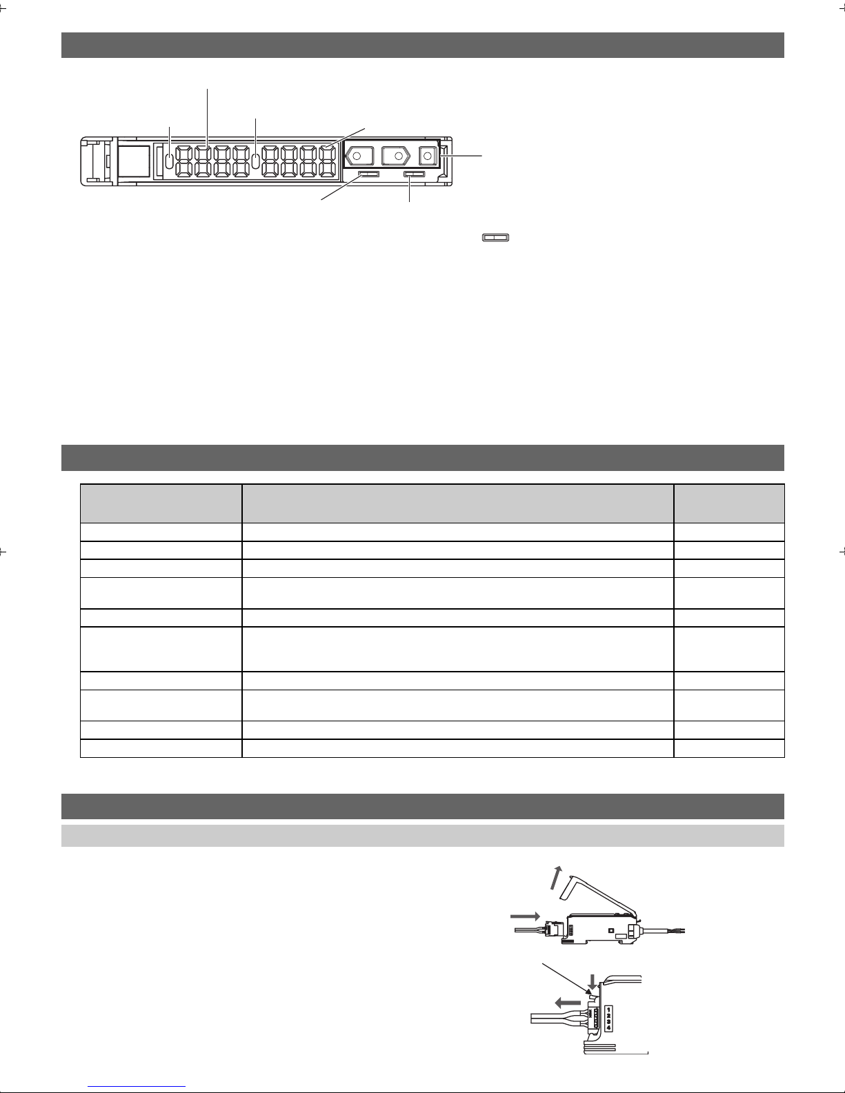
1. Part Names and Functions
(2) Main display (red display)
(3) Twin output model: Operation indicator (2CH side)
(1) Operation indicator
(1CH)
Analog output model: None
(4) Sub-display (green display)
UP
DOWN MODE
SET RUN
12
(7) Control keys
(5) SET/RUN switch
(6) Twin output type: Channel switch
Analog output type: Operating mode switch
NF
(1) This indicator lights when the output turns ON.
In the case of the twin output model, this indicator lights when the output of 1CH turns ON.
(2) This display shows the distance to the workpiece and function name.
(3) In the case of the twin output model, this indicator lights when the output of 2CH turns ON.
(4) This sub-display shows additional information and function settings for sensing.
(5) This switch selects the operating mode.
(6) In the case of the twin output model, this switch selects the channel to be displayed and set.
In the case of the analog output model, this switch selects whether to turn output ON when the workpiece is in the near
distance or the workpiece is in the far distance.
(7) These keys switch the display and set functions.
2. List of Functions
Function Name Overview
Operating mode setting This function sets the operating mode. P.7
Threshold setting This function sets the threshold values. P.8
Bank setting/call This function saves and reads settings. P.10
Scaling setting This function changes the display values for specific measurement values to the
desired values. (twin output model only)
Judgment output setting This function selects the output method. P.12
Analog output range setting This function sets the range and display ratio of the analog output with respect to the
display value.
(analog output model only)
Zero reset/offset This function sets the current distance to 0 (zero) or to any value. P.15, P.15
Display inversion This function inverts how the display for the distance to the workpiece is
incremented/decremented.
Keylock This function disables key operation. P.16
Initialization This function returns the amplifier settings to their factory settings. P.16
Page for Description
of Operation
P. 11
P. 1 3
P. 1 5
3. Installation & Connection
Connecting the Sensor Head
1. Open the protective cover.
2. Orient the Amplifier Unit so that the lock lever of the Sensor
Head connector is facing up, and push the Sensor Head into the
connector insertion slot as far as it can go.
To remove the Sensor Head, press down on the lock lever and draw
the Sensor Head out.
1
2
Lock lever
- 3 -
Page 4
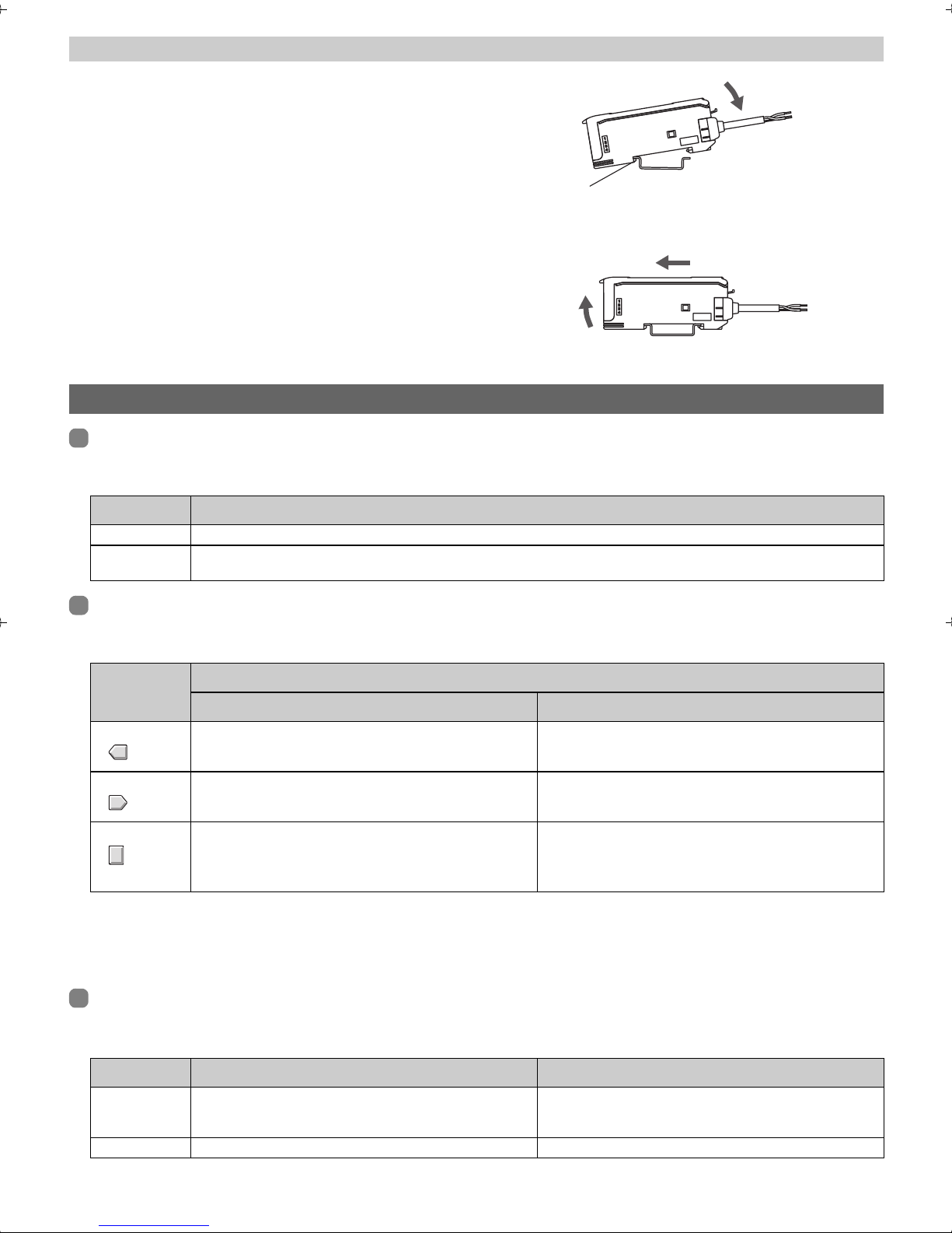
Installing the Amplifier Unit
JInstallation procedure
Hook the Sensor Head connector end of the Amplifier Unit on the
DIN Track and press in at the bottom until the Amplifier Unit locks
into place.
Be sure to mount the Amplifier Unit by hooking the Sensor Head
connector end of the Amplifier Unit on the DIN Track.
Hooking the other end may impair the mounting strength of the DIN
Track attachment.
JRemoval procedure
Push the Amplifier Unit in direction 1 and pull out the Sensor Head
connector end in direction 2.
4. Basic Knowledge for Operation
Switching Modes
To switch the operating mode, use the SET/RUN Switch.
Switch to the desired mode before operating the Amplifier Unit.
Mode Details
SET Select this mode to set the sensing conditions or threshold value by teaching.
RUN Select this mode to perform actual sensing or to set the following:
Manual adjustment of the threshold value, power adjustment, zero reset, key lock
Key Operations
Use the Control Keys to change the display and set sensing conditions.
The currently selected mode determines the key functions.
DIN track
Hook on sensor head connector
1
2
DIN track
Key
UP key Increases the threshold value. The function changes depending on the settings.
DOWN key Decreases the threshold value. The function changes depending on the settings.
MODE key
The function changes depending on the "MODE key
setting".
• Executes a zero reset
• Teaching with and without a workpiece
RUN Mode SET Mode
Function
• Executes teaching.
• Changes the setting value in the forward direction.
• Executes teaching.
• Changes the setting value in the reverse direction.
Changes the display to the function to be set.
About key pressing time
Unless otherwise mentioned in text descriptions, press keys for about one second.
Example: Press the UP key.
This means that you hold down the key for about one second and then release the key.
Reading Displays
The data displayed on the main and sub-displays depends on the currently selected mode. When the power is first turned
ON after shipment, RUN mode data is displayed.
Mode Main Display (Red Display) Sub-Display (Green Display)
SET Displays distance values and function names in order when
the Control Keys are pressed.
RUN* Displays the current distance value. (default) Displays the current threshold value. (default)
Displays the threshold values and setting values of
functions currently displayed on the main display in order
when the Control Keys are pressed.
* Display details can be changed by the display switch function. Refer to "Function Transition Charts" in "5. Function
Overview."
- 4 -
Page 5
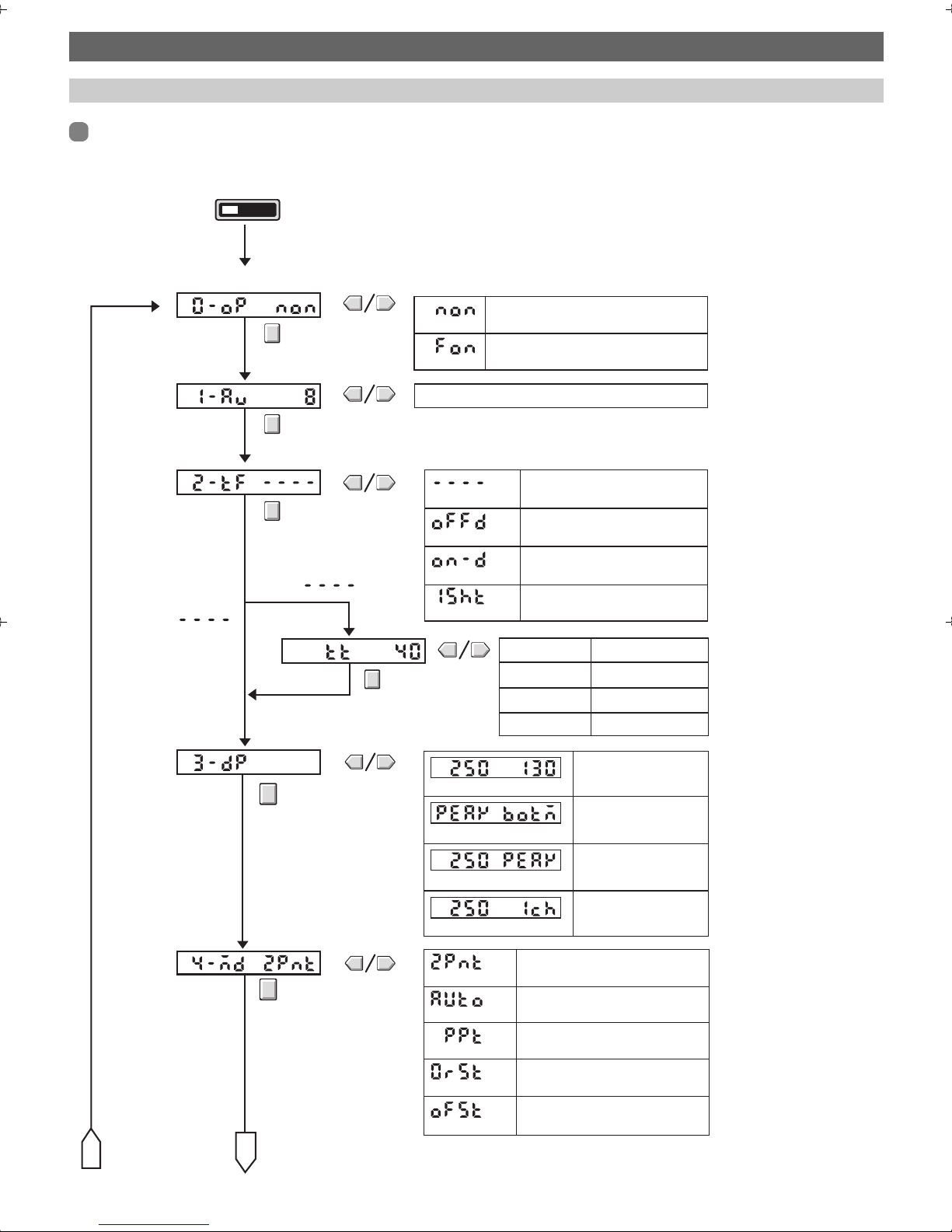
5. Function Overview
Function Transition Charts
SET mode
The following function can be set in SET mode.
The following explanation is for the SET mode on both the twin output model and analog output model.
Switch to the SET mode.
RUNSET
0. Operation mode
* In the case of an analog output, "0. Operation mode" is not provided.
Near distance ON
NON
Far distance ON
1. Number of samples
to average
2. Timer
FON
1 to 256
3. Display switch
4. MODE key setting
Not
Timer time
----
OFFD
ON-D
1SHT
Current distance Threshold value
PEAK BOTM
Current distance PEAK
Current distance Channel
2PNT
Timer disabled.
OFF-delay timer
ON-delay timer
One-shot timer
20 ms to 200 ms
Teaching with and without a
workpiece
1 ms increments1 to 20 ms
5 ms increments
100 ms increments200 ms to 1 s
1 s increments1 s to 5 s
Current distance
and threshold value
Distance between the
nearest workpiece on the
Near side and the farthest
workpiece within the Far side
Current distance
and distance at peak
Current distance
and channel No.
A
B
AUTO
PPT
0RST
OFST
- 5 -
Automatic-teaching
Position teaching
Executes a zero reset
Offset
Page 6
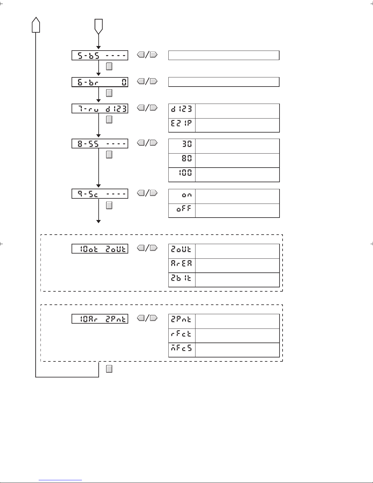
A
5. Bank selection
6. Bank registration
7. Display orientation
8.
Sensor model selection
9. Scaling
B
0 to 3
0 to 3
Normal display
D123
E21P
Reversed display
E4C-DS30
30
E4C-DS80
80
E4C-DS100
100
Scaling set
ON
Scaling not set
OFF
* In the case of the twin output model
10. Output method setting
* In the case of the analog output model
10. Output area setting
2OUT
AREA
2BIT
2PNT
RFCT
MFCS
Output on each channel
This is output only when there is a workpiece
between two threshold value distances.
2BIT output
Range of two preSET points is
output as 1 to 5 V.
Near-distance side rated distance to background setting range is output as 1 to 5 V.
Range of two points preset by
direct entry is output as 1 to 5 V.
- 6 -
Page 7

6. Basic Settings
N
p
1. Setting the Head Type
Initial setting of the head type
Set the head type when the power is first turned ON after the Amplifier Unit is purchased.
JSetting procedure
When the power is first turned ON, the following is displayed.
Sub-display:Main display:
Select the model (30, 80, 100) by the UP or DOWN key,
and then press the MODE key to apply the setting.
(In this example, E4C-DS30(L) is selected.)
The sub-display stops flashing and lights.
After one second, measurement starts.
Note: The head type does not need to be set from the second time that the power is turned ON.
Changing the head type
This feature is used to display the type of head to connect the
Amplifier Unit to.
Switch the SET/RUN switch to SET and change the head type by
following the procedure below.
SET
RU
JChange procedure
Sub-display:Main display:
Select [8-SS] by the MODE key.
Select the model (30, 80, 100) by the UP or DOWN key,
and then press the MODE key to apply the setting.
(In this example, E4C-DS30(L) is selected.)
Switch the SET/RUN switch to RUN.
RUNSET
This com
letes setting, and the display returns to regular measurement.
2. Setting the Operating Mode
Select whether to turn output ON when the distance between workpiece and the Sensor Head is shorter than the threshold
value (near distance) or when it is longer than the threshold value (far distance).
Selection Details
NON (near ON)
(default)
FON (far ON) Output turns ON when the distance between the workpiece and the Sensor Head is longer than the threshold value.
Output turns ON when the distance between the workpiece and the Sensor Head is shorter than the threshold value.
• The setting method varies depending on the Amplifier Unit model.
Model Method
Twin output model The setting method is set by the "operating mode" in the SET mode.
Analog output
model
Refer to "Function Transition Charts" in "5. Function Overview."
Select this method by the operating mode switch.
FN
- 7 -
Page 8

3. Setting Threshold Values
1) Teaching settings
(1) Teaching with and without a workpiece
Set two points one with a workpiece and another without a workpiece to be respectively sensed, and set the point between
these two points as the threshold value. This setting can be made in both of the RUN and SET modes.
When this setting is made in the RUN mode, make sure that the "MODE key setting" function is set to [2PNT]. The default
setting is [2PNT]. Refer to "Function Transition Charts" in "5. Function Overview."
Operation
RUN
mode
operation
SET
mode
operation
Display
RUNSET
Switch to the
RUN mode.
RUNSET
Switch to the
SET mode.
Hold down the MODE key
for more than 3 seconds.
Press the UP or
DOWN key.
The sub-display flashes.
Workpiece
Workpiece present
More than
3 seconds
TECH -
No workpiece present
More than
3 seconds
Hold down the MODE key
for more than 3 seconds
Press the UP or
DOWN key.
2PNT Threshold
value
The preset threshold value
flashes twice.
RUNSET
Switch to the
RUN mode.
(2) Teaching without a workpiece (background teaching)
Set the threshold value referenced to a state in which a workpiece is not present (background).
Set the threshold value 10% in front the sensing range width referenced to the distance in a workpiece absent state.
Example: In the case of a 50 to 300 mm type, set the threshold value about 25 mm in front.
Operation
RUNSET
Switch to the
SET mode.
Display
No workpiece present
Press the UP or
DOWN key
TECH -
The sub-display flashes
More than
3 seconds.
Hold down the UP or DOWN
key for more than 3 seconds.
RFCT Threshold
The preset threshold
value flashes twice.
value
- 8 -
RUNSET
Switch to the
RUN mode.
Page 9

(3) Automatic-teaching (set by a moving workpiece)
Measure the sensing distance while the key is held down, and set the value between the minimum and maximum distance
values as the threshold value.
Before making this setting, make sure that the MODE key setting is set to [AUTO]. The default setting is [2PNT]. Refer to
"Function Transition Charts" in "5. Function Overview."
Operation
Display
Workpiece Workpiece
Hold down the MODE key
for more than 3 seconds.
Sensing distance AUTO
"AUTO" is displayed as the subdisplay value, and sampling of
the sensing distance is started.
Workpiece
AUTO Threshold
The preset threshold
value flashes twice.
value
(4) Position teaching
Set the sensing distance of the workpiece as the threshold value.
Before making this setting, make sure that the MODE key setting is set to [PPT]. The default setting is [2PNT]. Refer to
"Function Transition Charts" in "5. Function Overview."
Operation
Workpiece Workpiece
Hold down the MODE key
for more than 3 seconds.
Workpiece
Display
PPT Sensing
"PPT" is displayed on the main
display and the preset threshold
value flashes on the sub-display.
Threshold
value
distance
"PPT" changes to the current
sensing distance to indicate that
the setting is completed.
Threshold
value
• Teaching error display
An error occurs if the following is displayed on the sub-display after teaching is executed.
Execute teaching again.
Flashes twice.
OVER
Flashes twice.
NEAR
OVER error
The taught distance is outside the sensing range.
Check the position of the workpiece, and then execute teaching again.
NEAR error
The difference between the maximum taught distance and the minimum
taught distance is too small.
Check the teaching position, and then execute teaching again.
(This error occurs with teaching with and without a workpiece, and
automatic-teaching.)
- 9 -
Page 10

2) Manual setting
N
N
(
)
Manually set the threshold value.
Operation
Switch to the RUN mode.
RUNSET
Set the threshold value by
the UP or DOWN key.
Increments the threshold value.
Decrements the threshold value.
Display
Sensing distance
Threshold value
4. Setting Banks
Switch the SET/RUN switch to SET and register by following the
procedure below.
JRegistration procedure
Sub-display:Main display:
Select [6-BR] by the MODE key.
Select the desired bank No. (0 to 3) by the UP or DOWN key.
(In this example, bank 2 is selected.)
Switch the SET/RUN switch to RUN.
RUNSET
Select YES by the UP or DOWN key,
and then press the MODE key to complete registration.
After about 3 seconds, the display returns
to the display set in the display setup.
SET
RU
The display returns to regular measurement.
Note: If you perform the following at this stage,
Selecting bank information
Switch the SET/RUN switch to SET and select the bank
information by following the procedure below.
JSelection procedure
Sub-display:Main display:
Press the MODE key.
registration is canceled.
• Select NO and press the MODE key.
• Set the SET/RUN switch to SET without
pressing the MODE key.
SET
RU
Select [5-BS] by the MODE key.
Select the desired bank No. (0 to 3) by the UP or DOWN key.
(In this example, bank 2 is selected.)
Switch the SET/RUN switch to RUN.
RUNSET
Selection is completed, and the display moves to [6-BR].
Refer to "Function Transition Charts in "5. Function Overview."
Registration is completed, and the display returns to regular measurement.
- 10 -
Page 11

5. Setting Scaling
JSetting procedure
Sub-display:Main display:
Select [9-SC] by the MODE key,
and then press the UP or DOWN key once.
Displays the current scaling execution state.
Press the UP or DOWN key to select "ON",
and press the MODE key to apply the setting.
Place the workpiece at the first point,
and press the MODE key.
Press the UP or DOWN key to set the distance,
and press the MODE key to apply the setting.
Place the workpiece at the second point,
and press the MODE key.
Press the UP or DOWN key to set the distance,
and press the MODE key to apply the setting.
(The display flashes twice.)
RUNSET
Switch the SET/RUN switch
to RUN.
This completes setting, and the display
returns to regular measurement.
The display moves to the next setting.
Press the MODE key.
(This display example is for a twin output model.)
Note: The scalable width is 1/2 to 2 times the current distance value.
Note: When the values of the first and second points are the same, "NEAR" flashes twice on the error display, and the points
must be set again.
Note: "OVER" is sometimes displayed and the setting cannot be made depending on the setting value. In this case, change
and then set the setting value again.
- 11 -
Page 12

JCancel procedure
g
N
(
)
)
Sub-display:Main display:
Select [9-SC] by the MODE key,
and then press the UP or DOWN key once.
Displays the current scaling execution state.
Press the UP or DOWN key to select [OFF],
and press the MODE key to cancel the setting.
(The display flashes twice.)
RUNSET
Switch the SET/RUN switch
to RUN.
This completes setting, and the display
returns to regular measurement.
The display moves to the next settin
Press the MODE key.
(This display example is for a twin output model.)
.
6. Output Settings
Setting the output method (twin output model)
The output method can be selected.
This function is mounted only on the twin output model.
Switch the SET/RUN switch to MODE, and select from [100T].
(Refer to "Function Transition Charts" in "5. Function Overview"
for detailed settings.)
SET
JOutput method details
Display Output method Overview Timing Chart (Near ON mode)
2OUT Output on each
channel
Independent control signals are output in
response to the threshold values of each
of channels 1CH and 2CH.
RU
1ch threshold value (a) 2ch threshold value (b
(ON)
(1ch)
(OFF)
(ON)
(2ch)
OFF
AREA Output during threshold
2BIT 2-bit output The distance is divided into four areas by
value
Control signals are output in response
during the threshold values of each of
channels 1CH and 2CH.
The regular independent control signal is
output for channel 1CH.
the threshold values of each of channels
1CH and 2CH and the three mid-points
between each of these threshold values.
Four states are judged according to the
relationship between the outputs of
channels 1CH and 2CH.
- 12 -
1ch threshold value (a) 2ch threshold value (b)
(ON)
(1ch)
(OFF)
(ON)
(2ch)
(OFF)
1ch threshold value (a) 2ch threshold value (b)
(ON)
(1ch)
(OFF)
(ON)
(2ch)
(OFF)
(a+b)/2
Page 13

Setting the output range (analog output model)
p
JFunction
• This function sets the range and display ratio of linear output with respect to the display value.
• This function is mounted only on the analog output model.
Note: The preset output range is canceled by initializing the product settings.
Note: When the output range is set, zero reset and offset are automatically cleared.
1) 2-point setting
• Determine the 1 V and 5 V ranges at the workpiece position.
• The output ramp is as follows according to the positional
relationship between the first and second points.
JSetting procedure
Sub-display:Main display:
5 V
First point
< second point
1 V
First point
5 V
First point
> second point
1 V
Second point
Select [10AR] by the MODE key,
and then press the UP or DOWN key to select [2PNT].
Press the MODE key to apply the setting.
The current distance is displayed on the sub-display.
Press the MODE key for 1 second or more to apply the setting.
Place the workpiece at the second point.
"B 5V" is displayed on the main display,
and the current distance is displayed on the sub-display.
Second point
oint
First
Press the MODE key for 1 second or more to apply the setting.
"OK" is displayed on the sub-display to indicate that the setting
is completed.
RUNSET
Switch the SET/RUN switch
to RUN.
This completes setting, and the display
returns to regular measurement.
The display moves to the next setting.
Press the MODE key.
Note: When the values of the first and second points are the same, "NEAR" flashes twice on the error display, and the points
must be set again.
2) Background setting
Set the analog output referenced to the background distance (5
V).
5 V
1 V
Nearest point
Distance to rear
- 13 -
Page 14

JSetting procedure
(mm)
(mm)
Sub-display:Main display:
Select [10AR] by the MODE key,
and then press the UP or DOWN key to select [RFCT].
Press the MODE key to apply the setting. The current
distance is displayed on the sub-display.
Align with the rear, and hold down the MODE key for
more than 3 seconds.
"OK" is displayed on the sub-display to indicate that
the setting is completed.
RUNSET
Switch the SET/RUN switch
to RUN.
This completes setting, and the display returns
to regular measurement.
The display moves to the next setting.
3) Direct setting
Directly set the distance with respect to output (1 V, 5 V).
JSetting procedure
Sub-display:Main display:
Press the MODE key.
Output voltage
(V)
5
1
0
50 300
Select [10AR] by the MODE key,
and then press the UP or DOWN key to select [MFCS].
The distance value currently assigned to 1 V is displayed.
Measured
value
Output voltage
(V)
5
1
0
100 200
Measured
value
RUNSET
Switch the SET/RUN switch
to RUN.
This completes setting, and the display
returns to regular measurement.
Note: When the values of the first and second points are the same, "NEAR" flashes twice on the error display, and the points
must be set again.
Press the UP or DOWN key to set the distance to assign to 1 V,
and press the MODE key to apply the setting.
The distance value currently assigned to 5 V is displayed.
Press the UP or DOWN key to set the distance to assign to 5 V,
and press the MODE key to apply the setting.
"OK" is displayed on the sub-display to indicate that the setting
is completed.
Press the MODE key.
The display moves to the next setting.
- 14 -
Page 15

7. Handy Ways of Setting Functions
g
Setting the Display to Zero (zero reset)
Before making this setting, make sure that the "MODE key setting" is set to [0RST] (zero reset).
The default setting is [2PNT] (teaching with and without a workpiece). (Refer to "Function Transition Charts" in "5. Function
Overview.")
JSetting method JCancel method
Switch to the RUN mode.
RUNSET
Hold down the MODE key
for more than 3 seconds.
The current distance
display stops fluctuating.
Current distance Threshold
value
The zero reset is
executed, and the
current distance display
es to "0".
chan
Current distance Threshold
+
Setting the Display to Any Value (offset)
Before making this setting, make sure that the "MODE key setting" is set to [oFST] (offset).
The default setting is [2PNT] (teaching with and without a workpiece). (Refer to "Function Transition Charts" in "5. Function
Overview.")
JSetting method JCancel method
Switch to the RUN mode.
RUNSET
Hold down the DOWN key for more
than 3 seconds
with the MODE key pressed.
Press the MODE key and then
immediately press the DOWN key.
The zero reset is
canceled.
value
Switch to the RUN mode.
RUNSET
Hold down the MODE key
for more than 3 seconds.
The current distance
display stops fluctuating.
Current distance Threshold
value
Press the UP or DOWN
key to change the
current distance.
Press the MODE key to
execute offset.
+
Current distance Threshold
Switch to the RUN mode.
RUNSET
Hold down the DOWN key for more
than 3 seconds with the MODE key
pressed.
Press the MODE key and then
immediately press the DOWN key.
The offset is
canceled.
value
Inverting the Increment/decrement Direction of the Main Display (display inversion)
When display inversion is executed, how the display to the reference distance is indicated is inverted.
Before making this setting, make sure that the MODE key setting is set to [0RST] (zero reset) or [oFST] (offset).
JSetting method JCancel method
(In the zero reset mode)
Current
distance
Display inversion is
executed together
with the zero reset.
Threshold
value
Switch to the RUN mode.
RUNSET
Hold down the UP key for more
than 3 seconds with the MODE
+
key pressed.
Press the MODE key and then
immediately press the UP key.
(In the offset mode)
Current
distance
Threshold
value
Press the UP
or DOWN key
to change the
current
distance.
Press the
MODE key to
execute display
inversion
together with
the offset.
Current
distance
+
Switch to the RUN mode.
RUNSET
Hold down the UP key for more
than 3 seconds with the MODE
key pressed.
Press the MODE key and then
immediately press the UP key.
Both zero reset (offset) and
Threshold
value
display inversion are
canceled.
- 15 -
Page 16

Keylock
JSetting method JCancel method
Switch to the RUN mode.
RUNSET
Hold down the UP key for more
than 3 seconds with the MODE
+
LOC ON
key pressed.
Press the MODE key and then
immediately press the UP key.
The sub-display flashes twice,
and key entry is disabled.
Initializing all Setting Data (initialization processing)
JSetting method
Switch to the SET mode.
RUNSET
+
INIT NO?
INIT GOOD
Hold down the UP and DOWN keys for
more than 3 seconds.
When "YES?" is displayed,
press the MODE key.
Initialization is completed.
YES?
NO?
Data is not
initialized.
Data is
initialized.
Switch to the RUN mode.
RUNSET
Hold down the UP key for more
than 3 seconds with the MODE
+
LOC OFF
key pressed.
Press the MODE key and then
immediately press the UP key.
The sub-display flashes twice,
and key entry is enabled.
The head type setting is not cleared even if all setting data is initialized.
Refer to "1. Setting the Head Type" in "6. Basic Settings."
- 16 -
Page 17

8. Ratings
Ratings and Specifications
Type Twin output model Analog output model
Model E4C-UDA11 E4C-UDA41 E4C-UDA11AN E4C-UDA41AN
NPNoutput PNPoutput NPNoutput PNPoutput
Connection method Prewired
Supply voltage 12 to 24 VDC ± 10%, ripple 10% max.
Current consumption 80 mA max.
Control output NPN open collector (26.4 VDC max.)
Hysteresis
Timer OFF/OFF-delay/ON-delay/one-shot
Timer time 1 ms to 5 s
Analog
output
Operating temperature Operating: -25 to +55°C Storage: -30 to +70°C (with no icing)
Operating humidity Operating and storage: 35% to 85% (with no condensation)
Insulation resistance 50 MΩ min. (by 500 VDC)
Dialectic strength 1,000 VAC, 50/60 Hz for 1 min
Vibration resistance 10 to 150 Hz, 0.75 mm double amplitude, 80 min each in X, Y, and Z directions
Shock resistance
Materials Case: PBT (polybutylene terephthalate), Cover: Polycarbonate
Weight Approx. 150 g
Accessories Instruction Manual
Output form - Voltage output (DC 1 to 5 V)
Connected load - 10 kΩ min.
Temperature
characteristics
Resolution - 2.0% F.S.max. *
Linearity - 2.0% F.S.max.
* Value one hour after the product is turned on. Note, however, that external disturbance sometimes causes minute output.
Load current: 50 mA max., Residual voltage: 1 V max.
2.0% F.S.max.
- 0.3% F.S./°C
500 mm/s2, 3 times each in X, Y and Z directions
I/O Circuit Diagrams
JE4C-UDA11 (NPN type) JE4C-UDA41 (PNP type)
Brown
Black 1CH output
Orange 2CH output
Internal circuit
Blue
Load
Load
DC
12 to 24 V
Internal circuit
JE4C-UDA11AN (NPN type) JE4C-UDA41AN (PNP type)
Brown
Black Control output
Orange Analog output
Internal circuit
Blue
Load
10 KW min.
Load
DC
12 to 24 V
Internal circuit
Brown
Black
Orange
Blue
Brown
Black control output
Orange
Blue
1CH
2CH
Analog
output
Load
output
output
10kǡ
MIN
DC
12 to 24 V
Load
Load
DC
12 to 24 V
Load
- 17 -
Page 18

External Dimensions
S
C
G
T
1
T
S
JE4C-UDA11/-UDA41
JE4C-UDA11AN/-UDA41AN
18.15
21.1
18.15
21.1
38.8
35.8
3.9 x 3=11.7
38.8
3.9 x 3=11.7
3.9 x 3=11.7
3.9 x 3=11.7
(Unit: mm)
(Unit: mm)
13.8
10
2.5 50.3
32
9.93.4
24.7
76
36.7
8.1
32
12.50
S
ens
ing
D
evices
D
ivision
hiokoji Horikawa, Shimogyo-ku,Kyoto, 600-8530 Japan Tel: (81)75-344-7068/Fax: (81)75-344-7107
R
e
gional
H
ea
OMRON EUR
ensor Business Unit,
arl-Benz-Str. 4, D-71154 Nufringen,
ermany
el: (49)7032-811-0/Fax: (49)7032-811-199
OMRON
East Commerce Drive, Schaumburg, IL 60173 U.S.A.
el: (1)847-843-7900/Fax: (1)847-843-8568
dquarters
OPE B.V.
ELECTRONICS LL
H.Q.
C
In the intereste of product improvement,specifications are subject to change without notice.
A
pplicat
OMRON C
ion Sensor
s
- 18 -
orporation
D
ivision
OMRON ASIA PAC
83 Clemenceau Avenue,
#11-01, UE Square,
239920 Singapore
Tel: (65)6835-3011/Fax: (65)6835-2711
OMRON (CHINA) C
Room 2211, Bank of China Tower,
200 Yin Cheng Road (M),
Shanghai, 200120 China
Tel: (86)21-5037-2222/Fax: (86)21-5037-2200
I
ndustrial
IFIC PTE. LTD.
O., LTD.
A
utomation
C
ompan
y
 Loading...