

Page 1

OPERATION MANUAL
CX-Integrator Ver. 1.1
SYSMAC
CXONE-AL
@@@@
C-E
Cat. No. W445-E1-02
Page 2

CXONE-AL@@C-E
CX-Integrator Ver. 1.1
Operation Manual
Revised November 2005
Page 3

iv
Page 4

g
p
j
y p
g
Notice:
OMRON products are manufactured for use according to proper procedures by a qualified operator
and only for the purposes described in this manual.
The following conventions are used to indicate and classify precautions in this manual. Always heed
the information provided with them. Failure to heed precautions can result in injury to people or
damage to property.
!DANGER Indicates an imminently hazardous situation which, if not avoided, will result in death or
serious injury. Additionally, there may be severe property damage.
!WARNING Indicates a potentially hazardous situation which, if not avoided, could result in death or
serious injury. Additionally, there may be severe property damage.
!Caution Indicates a potentially hazardous situation which, if not avoided, may result in minor or
moderate injury, or property damage.
OMRON Product References
All OMRON products are capitalized in this manual. The word “Unit” is also capitalized when it refers
to an OMRON product, regardless of whether or not it appears in the proper name of the product.
The abbreviation “Ch,” which appears in some displays and on some OMRON products, often means
“word” and is abbreviated “Wd” in documentation in this sense.
The abbreviation “PLC” means Programmable Controller. “PC” is used, however, in some
Programming Device displays to mean Programmable Controller.
Visual Aids
The following headings appear in the left column of the manual to help you locate different types of
information.
Note Indicates information of particular interest for efficient and convenient
operation of the product.
1,2,3... 1. Indicates lists of one sort or another, such as procedures, checklists, etc.
OMRON, 2005
All rights reserved. No part of this publication may be reproduced, stored in a retrieval system, or transmitted, in any form,
or by any means, mechanical, electronic, photocopying, recordin
OMRON.
atent liability is assumed with respect to the use of the information contained herein. Moreover, because OMRON is
No
constantly striving to improve its high-quality products, the information contained in this manual is sub
without notice. Ever
responsibility for errors or omissions. Neither is any liability assumed for damages resultin
contained in this publication.
recaution has been taken in the preparation of this manual. Nevertheless, OMRON assumes no
, or otherwise, without the prior written permission of
ect to change
from the use of the information
v
Page 5

vi
Page 6

TABLE OF CONTENTS
PRECAUTIONS
1 Intended Audience.......................................................................................................... xvi
2 Safety Precautions.......................................................................................................... xvi
3 Application Precautions .................................................................................................xviii
4 Operating Environment Precautions................................................................................ xx
5 Guide to Version Upgrade ..............................................................................................xxi
Section 1 Overview
1-1 The CX-Integrator ........................................................................................................ 1-2
1-2 Specifications............................................................................................................... 1-8
1-3 Installation.................................................................................................................. 1-14
1-4 PLC Connecting Cables ............................................................................................ 1-15
1-5 Window Descriptions ................................................................................................. 1-22
1-6 Menus ........................................................................................................................ 1-34
Section 2 Basic Operations
2-1 Basic Procedures......................................................................................................... 2-2
2-2 Connecting Online to the Relay PLC......................................................................... 2-10
2-3 Uploading Network Configurations and Checking for Communications Unit Errors . 2-21
2-4 Switching the Target PLC .......................................................................................... 2-27
2-5 Creating Virtual Network Configurations Offline........................................................ 2-29
2-6 Manipulating Component Parameters ....................................................................... 2-38
2-7 Uploading, Downloading, and Comparing Network Parameters ............................... 2-43
2-8 Comparing Network Configurations........................................................................... 2-44
2-9 File Operations .......................................................................................................... 2-45
2-10 Target PLC Online Operations .................................................................................. 2-49
2-11 Starting Specified Applications .................................................................................. 2-51
2-12 Printing....................................................................................................................... 2-52
Section 3 Routing Tables
3-1 Routing Table Overview .............................................................................................. 3-2
3-2 Setting the Routing Tables .......................................................................................... 3-9
3-3 Maintenance after Network Configuration ................................................................. 3-25
Section 4 Data Links for Controller Link and SYSMAC LINK
4-1 Overview...................................................................................................................... 4-2
4-2 User Interface Overview .............................................................................................. 4-4
4-3 Manually Setting Data Links ........................................................................................ 4-8
4-4 Automatically Set Data Links ..................................................................................... 4-41
Section 5 Ethernet
5-1 Broadcast Node Search .............................................................................................. 5-2
5-2 Ping Test...................................................................................................................... 5-4
vii
Page 7

Section 6 DeviceNet
6-1 DeviceNet Setting Procedures..................................................................................... 6-2
6-2 Setting Slave Parameters ............................................................................................6-4
6-3 Adding Slaves to the Master ........................................................................................ 6-8
6-4 Setting Master Properties .......................................................................................... 6-13
6-5 Editing Master Parameters ........................................................................................ 6-15
6-6 Parameter Wizard ...................................................................................................... 6-16
6-7 Master Parameter Editing Details (Tab Descriptions) ............................................... 6-21
6-8 Manual I/O Allocations ............................................................................................... 6-29
6-9 Advanced Settings (Connection, Communication Cycle Time, Slave Function Settings,
Etc.)............................................................................................................................ 6-36
6-10 Creating and Editing I/O Comments .......................................................................... 6-43
6-11 Displaying Device Properties..................................................................................... 6-45
6-12 Downloading the Network Configuration/Device Parameters to Devices.................. 6-51
6-13 Uploading and Verifying Device Parameters ............................................................. 6-57
6-14 Monitoring Devices .................................................................................................... 6-62
6-15 Using General-purpose Tools to Set Devices ........................................................... 6-70
6-16 Optional Functions ..................................................................................................... 6-72
Section 7 CompoWay/F
7-1 CompoWay/F System Configuration ........................................................................... 7-2
7-2 CompoWay/F Slaves Connected to a PLC ................................................................. 7-3
7-3 CompoWay/F Slaves Connected to a Computer....................................................... 7-10
Section 8 NT Links
8-1 NT Link Connection Auto-detect Function ................................................................... 8-2
8-2 Transferring Screen Data through the PLC ................................................................. 8-6
Section 9 Network Testing
9-1 Controller Link Network Diagnostic Tool...................................................................... 9-2
9-2 Echoback Test between Nodes ................................................................................. 9-22
9-3 Ethernet Ping Test ..................................................................................................... 9-25
Appendices
A-1 CPS File Management................................................................................................. A-2
A-2 EDS File Management................................................................................................. A-4
Revision History
viii
Page 8

About this Manual:
!
This manual describes the installation and operation of CX-Integrator and includes the sections
described below.
Please read this manual carefully and be sure you understand the information provided before
attempting to use the CX-Integrator. Be sure to read the precautions provided in the following section.
Precautions provides general precautions for using the CX-Integrator.
Section 1 outlines the functions of the CX-Integrator and describes the menus and connecting to
networks.
Section 2 describes the basic operations required to use the CX-Integrator.
Section 3 describes how to set routing tables.
Section 4 describes how to set data links for Controller Link and SYSMAC LINK Networks.
Section 5 describes the how to use the diagnostic tools for Controller Link Networks.
Section 6 describes settings and operations unique to DeviceNet Networks, including registering
slaves in the master, allocating I/O, monitoring devices, etc.
Section 7 describes settings and operations unique to CompoWay/F Networks.
Section 8 settings and operations unique to NT Links.
The Appendix describes CPS files for Ethernet, Controller Link, CompoWay/F, and NT Link
Networks and EDS files for DeviceNet Networks.
WARNING Failure to read and understand the information provided in this manual may result in
personal injury or death, damage to the product, or product failure. Please read each
section in its entirety and be sure you understand the information provided in the section
and related sections before attempting any of the procedures or operations given.
ix
Page 9

Manuals Related to the CX-Integrator
Cat No. Models Name Description
W445
(this manual)
W444
W446 WS02-CXPC1-E-V60 CX-Programmer Ver. 6.1
W447 WS02-CXPC1-E-V60
CXONE-AL@@C-E
CXONE-AL@@C-E
CS1G-CPU@@H
CS1H-CPU@@H
CJ1G- CPU@@H
CJ1H- CPU@@H
CJ1M- CPU@@
CP1H- X@@@@-@
CP1H- XA@@@@-@
CX-Integrator Operation
Manual
CX-One Setup Manual Describes installation and provides an
Operation Manual
CX-Programmer Ver. 6.1
Operation Manual:
Function Blocks
Describes CX-Integrator operating
methods, e.g., for setting up and
monitoring networks.
overview of the CX-One FA Integrated
Tool Package.
Describes CX-Programmer operations
except those related to function blocks.
Describes function blocks for
CS/CJ-series CPU Units unit version 3.0
or later and CP-series CPU Units, and
CX-Programmer operations related to
function blocks.
Refer to the W447 manual above for other
CX-Programmer operations.
Manuals Related to DeviceNet
Cat No. Models Name Description
W267 --- DeviceNet Operation
Manual
W380 CS1W-DRM21(-V1)
CJ1W-DRM21
W379 C200HW-DRM21-V1
CVM1-DRM21-V1
W381 3G8F7-DRM21 DeviceNet PCI Board
DeviceNet Unit Operation
Manual
DeviceNet Master Unit
Operation Manual
Operation Manual
Describes network communications
settings and wiring common to all
DeviceNet networks.
Describes CX/CJ-series DeviceNet Units.
Describes C200H and CV/CVM1-series
DeviceNet Master Units.
Describes the DeviceNet PCI Board.
x
Page 10

Read and Understand this Manual
Please read and understand this manual before using the product. Please consult your OMRON
representative if you have any questions or comments.
Warranty and Limitations of Liability
WARRANTY
OMRON's exclusive warranty is that the products are free from defects in materials and workmanship for a
period of one year (or other period if specified) from date of sale by OMRON.
OMRON MAKES NO WARRANTY OR REPRESENTATION, EXPRESS OR IMPLIED, REGARDING
NON-INFRINGEMENT, MERCHANTABILITY, OR FITNESS FOR PARTICULAR PURPOSE OF THE
PRODUCTS. ANY BUYER OR USER ACKNOWLEDGES THAT THE BUYER OR USER ALONE HAS
DETERMINED THAT THE PRODUCTS WILL SUITABLY MEET THE REQUIREMENTS OF THEIR
INTENDED USE. OMRON DISCLAIMS ALL OTHER WARRANTIES, EXPRESS OR IMPLIED.
LIMITATIONS OF LIABILITY
OMRON SHALL NOT BE RESPONSIBLE FOR SPECIAL, INDIRECT, OR CONSEQUENTIAL DAMAGES,
LOSS OF PROFITS OR COMMERCIAL LOSS IN ANY WAY CONNECTED WITH THE PRODUCTS,
WHETHER SUCH CLAIM IS BASED ON CONTRACT, WARRANTY, NEGLIGENCE, OR STRICT
LIABILITY.
In no event shall the responsibility of OMRON for any act exceed the individual price of the product on
which liability is asserted.
IN NO EVENT SHALL OMRON BE RESPONSIBLE FOR WARRANTY, REPAIR, OR OTHER CLAIMS
REGARDING THE PRODUCTS UNLESS OMRON'S ANALYSIS CONFIRMS THAT THE PRODUCTS
WERE PROPERLY HANDLED, STORED, INSTALLED, AND MAINTAINED AND NOT SUBJECT TO
CONTAMINATION, ABUSE, MISUSE, OR INAPPROPRIATE MODIFICATION OR REPAIR.
xi
Page 11

Application Considerations
SUITABILITY FOR USE
OMRON shall not be responsible for conformity with any standards, codes, or regulations that apply to the
combination of products in the customer's application or use of the products.
At the customer's request, OMRON will provide applicable third party certification documents identifying
ratings and limitations of use that apply to the products. This information by itself is not sufficient for a
complete determination of the suitability of the products in combination with the end product, machine,
system, or other application or use.
The following are some examples of applications for which particular attention must be given. This is not
intended to be an exhaustive list of all possible uses of the products, nor is it intended to imply that the
uses listed may be suitable for the products:
•Outdoor use, uses involving potential chemical contamination or electrical interference, or conditions or
uses not described in this manual.
•Nuclear energy control systems, combustion systems, railroad systems, aviation systems, medical
equipment, amusement machines, vehicles, safety equipment, and installations subject to separate
industry or government regulations.
•Systems, machines, and equipment that could present a risk to life or property.
Please know and observe all prohibitions of use applicable to the products.
NEVER USE THE PRODUCTS FOR AN APPLICATION INVOLVING SERIOUS RISK TO LIFE OR
PROPERTY WITHOUT ENSURING THAT THE SYSTEM AS A WHOLE HAS BEEN DESIGNED TO
ADDRESS THE RISKS, AND THAT THE OMRON PRODUCTS ARE PROPERLY RATED AND
INSTALLED FOR THE INTENDED USE WITHIN THE OVERALL EQUIPMENT OR SYSTEM.
PROGRAMMABLE PRODUCTS
OMRON shall not be responsible for the user's programming of a programmable product, or any
consequence thereof.
xii
Page 12

Disclaimers
CHANGE IN SPECIFICATIONS
Product specifications and accessories may be changed at any time based on improvements and other
reasons.
It is our practice to change model numbers when published ratings or features are changed, or when
significant construction changes are made. However, some specifications of the products may be changed
without any notice. When in doubt, special model numbers may be assigned to fix or establish key
specifications for your application on your request. Please consult with your OMRON representative at any
time to confirm actual specifications of purchased products.
DIMENSIONS AND WEIGHTS
Dimensions and weights are nominal and are not to be used for manufacturing purposes, even when
tolerances are shown.
PERFORMANCE DATA
Performance data given in this manual is provided as a guide for the user in determining suitability and
does not constitute a warranty. It may represent the result of OMRON's test conditions, and the users must
correlate it to actual application requirements. Actual performance is subject to the OMRON Warranty and
Limitations of Liability.
ERRORS AND OMISSIONS
The information in this manual has been carefully checked and is believed to be accurate; however, no
responsibility is assumed for clerical, typographical, or proofreading errors, or omissions.
xiii
Page 13

xiv
Page 14

PRECAUTIONS
This section provides precautions for using the CX-Integrator.
The information contained in this section is important for the safe and reliable application of the CX-Integrator.
You must read this section and understand the information contained before attempting to use the
CX-Integrator.
1 Intended Audience.......................................................................................... xvi
2 Safety Precautions .......................................................................................... xvi
3 Application Precautions.................................................................................. xviii
4 Operating Environment Precautions............................................................... xx
5 Guide to Version Upgrade.............................................................................. xxi
Page 15

1 Intended Audience
1 Intended Audience
This manual is intended for the following personnel, who must also have
knowledge of electrical systems (an electrical engineer or the equivalent).
• Personnel in charge of installing FA systems
• Personnel in charge of designing FA systems
• Personnel in charge of managing FA systems and facilities
2 Safety Precautions
!Caution When performing any of the following operations, always check the network
address and node address of the other node (PLC) and the node address
and unit number of the mounted Unit (PLC CPU Bus Unit or Special I/O Unit)
or the node address of the Component (DeviceNet Master/Slave or
CompoWay/F Slave), and be sure that these operations can be performed
safely for the current status of the node (Unit or Component):
• Transferring parameter or program data to the other node
• Changing the operating mode of the other node
Unexpected operation may result if parameter or program data is transferred
to the wrong node (DeviceNet Master/Slave or CompoWay/F Slave), the
operating mode of the wrong node is changed, or the other node is not in a
suitable status to receive the program or parameter data or the operating
mode change.
!Caution When changing the target PLC to any PLC other than the relay PLC, check
the node address and node number of the target PLC carefully before
executing the change. Unexpected operation and injury may result if the
wrong PLC is set as the target PLC.
• Changing the operating mode
• Transferring or verifying user-set data link tables
• Transferring or verifying routing tables
• Performing I/O table operations (including transferring CPU Bus Unit or
Special I/O Unit parameters)
Note Operations performed from the CX-Integrator are performed for the target
PLC, which is not necessarily the same as the relay PLC.
!Caution When transferring parameters that have been created or edited on the
computer to actual Units (PLC CPU Bus Units or PLC Special I/O Units) or to
actual Components (DeviceNet Masters/Slaves or CompoWay/F Slaves),
always check the identifying number of the actual Units or Components (i.e.,
the unit numbers and unit addresses or node addresses) before executing
the transfer. Unexpected operation and injury may result if parameters are
transferred to the wrong Unit or Component.
xvi
!Caution When changing or removing a routing table (see note), be sure to update the
display for the Online Connection Information Window. The display for the
Online Connection Information Window could possibly be different from the
actual network status. If operations are executed without first updating the
display, particularly online operations in the Network Configuration Window, it
could cause data to be mistakenly read or written for the wrong network or
node address or unit number.
Page 16

2 Safety Precautions
Note: Changing or removing a routing table refers to using the
CX-Integrator (or a CX-Integrator for another personal computer) to
start the Routing Table Component and then changing or removing
a routing table for the target PLC (either a local network table or a
relay network table).
!Caution Do not execute a broadcast node search if a node exists for something other
than an OMRON Ethernet Unit or FinsGateway within the same segment on
Ethernet, and when the Ethernet network system is in operation. When a
broadcast node search is executed, an OMRON FINS command is sent to all
nodes in the segment. Therefore, if a node exists for something other than an
OMRON Ethernet Unit or FinsGateway, the FINS command will not be
received at that node and unexpected operation may occur.
xvii
Page 17

3 Application Precautions
3 Application Precautions
Observe the following precautions when using the CX-Integrator.
General Communications Precautions
• Do not turn OFF the power to the PLC or disconnect the cable connecting
the PLC when the CX-Integrator is online with the PLC. Doing so may cause
the computer running CX-Integrator to malfunction.
• Before changing the operating mode, always confirm that doing so will not
adversely affect system operation.
• Always check the operation of parameters sufficiently before using them for
actual system operation.
• Confirm that resetting CPU Bus Units and Special I/O Units will not
adversely affect system operation before resetting these Units.
DeviceNet
• Enable the scan list to before operating the system.
• When adding a new node to the network, make sure that the baud rate is
the same as other nodes.
• Use specified communications cables.
• Do not extend connection distances beyond the ranges given in the
specifications.
• Always turn OFF the power supply to the personal computer, Slaves, and
Communications Units before attempting any of the following.
• Attaching or detaching the DeviceNet Board or Card
• Assembling the Units
• Setting rotary switches
• Connecting or wiring the cables
• Connecting or disconnecting connectors
• Be sure that the communications cables and other items with locking
devices are properly locked into place.
• Observe the following precautions when wiring the communications cable.
• Separate the communications cables from the power lines or
high-tension lines.
• Do not bend the communications cables.
xviii
• Do not pull on the communications cables.
• Do not place heavy objects on top of the communications cables.
• Be sure to wire communications cable inside ducts.
• Use appropriate communications cables.
• Before touching the PCI Board, be sure to first touch a grounded metallic
object in order to discharge any static build-up. Not doing so may result in
malfunction or damage.
• When transporting a Board or Card, use the special box in which it was
shipped to protect the LSIs and ICs from being damaged. Also do not
subject the Board or Card to excessive vibration or shock.
Page 18

3 Application Precautions
•
Because the devices are reset in order, communications errors will
temporarily occur in the master and slaves. For this reason, do not
download the network configuration while the master-side PLC (CPU Unit)
is operating.
• When downloading the network configuration, each of the devices is reset.
If the Master Unit is reset first, it may cause errors in writing parameters to
the subsequent slaves. For that reason, this method (downloading the
network configuration) should be used only when the Master Unit has been
given the highest address.
• Downloaded device parameters will be valid only after the devices are reset
unless they are the OMRON CVM1-DRM21-V1, C200HW-DRM21-V1,
CS1W-DRM21(-V1), or CJ1W-DRM21.
• When the devices are reset, communications errors will temporarily occur.
For this reason, do not reset the devices while the master-side PLC (CPU
Unit) is operating.
Data Links in Controller Link or SYSMAC LINK Networks
• The data link mode (manual setting or automatic setting) and data link
method are determined according to the data link setting in the startup node.
In the startup node, set a data link table for manual settings and data link
automatic setting parameters for automatic settings. If the settings are
incorrect, the data links will not start.
Check the following items before starting data links.
(1) Manually Set Data Links
Check the data link tables in each node participating in the data link to
see that they are correct.
Be sure that data link tables are deleted from nodes that are not
participating in the data links.
(2) Automatically Set Data Links
Be sure that the correct DM parameters have been set in the data link
startup node.
• If incorrect data link tables or parameters are set, injury may result due to
unexpected operation of the system. Even if the correct data link tables and
parameters have been set, do not start or stop data links before verifying
that there will be no adverse influence on the system.
Routing Tables
CPU Bus Units are reset when routing tables are transferred from a
Programming Device to a PLC to allow set routing tables to be read. Make
sure that resetting CPU Bus Units will not cause equipment damage or
dangerous system behavior before transferring tables.
xix
Page 19

4 Operating Environment Precautions
4 Operating Environment Precautions
!Caution Perform installation properly, according to the procedures described in this
manual.
!Caution Do not install in the following locations:
• Locations subject to direct sunlight
• Locations subject to temperatures or humidity outside the range specified in
the specifications
• Locations subject to condensation as the result of severe changes in
temperature
• Locations subject to corrosive or flammable gases
• Locations subject to dust (especially iron dust) or salts
• Locations subject to exposure to water, oil, or chemicals
• Locations subject to shock or vibration
!Caution Take appropriate and sufficient countermeasures when installing in the
following locations:
• Locations subject to static electricity or other forms of noise
• Locations subject to strong electromagnetic fields
• Locations subject to possible exposure to radioactivity
• Locations close to power supplies
xx
Page 20

5 Guide to Version Upgrade
5 Guide to Version Upgrade
The following table shows the changes in the upgrade from CX-Integrator
Ver. 1.0 to Ver. 1.1.
Item Previous (Ver. 1.0) Ver. 1.1
CP1H supported as PLC model
Automatic
online
connection
Ethernet network PING test
Echoback test between nodes
on Ethernet, Controller Link,
SYSMAC LINK, and DeviceNet
Controller Link network
diagnosis Repeater display
Start Special Application
Support for NSJ Series
Automatic
USB
connection
No Yes
No
No Yes
No Yes. (Response time can be
No Branching information can be
No It is possible to select an Inverter
No Yes
Yes. When Automatic USB
Connection is selected from the
Network Menu, the PLC model
(such as the CP1H) is
automatically recognized and
connected online.
measured.)
displayed by Repeater Units.
on DeviceNet, and to start the
CX-Drive.
xxi
Page 21

1
Communications
Section 1 Overview
This section provides an overview of the CX-Integrator and describes CX-Integrator
menus and connections.
Page 22
1-1 The CX-Integrator
1-1-1 Overview
1-1 The CX-Integrator
1-1-1 Overview
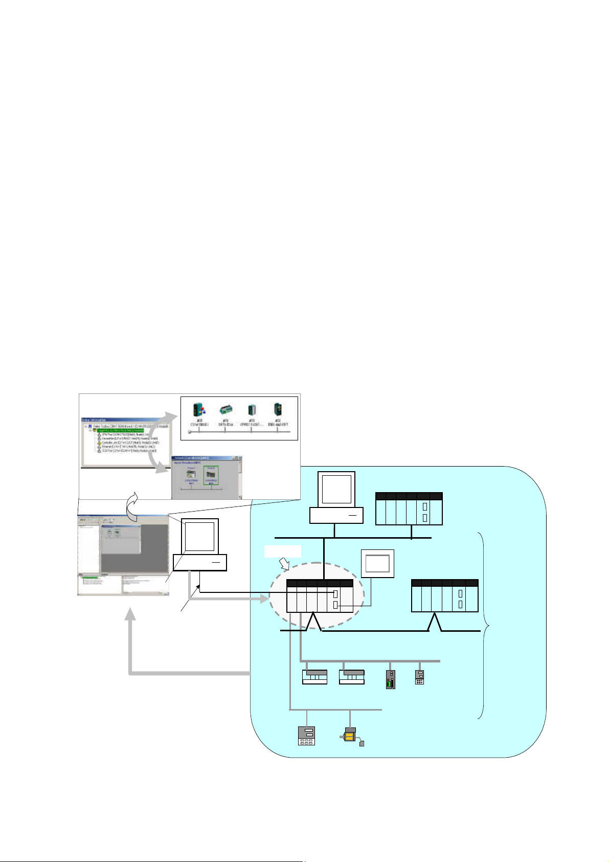
The CX-Integrator is a Programming Device software package that enables reading the
PLC's network and serial network configuration from a personal computer via an online
connection. This enables easily performing many operations, such as monitoring the
connection status of various networks, setting parameters, and diagnosing networks.
The CX-Integrator can be placed online manually or automatically with the CS/CJ-series
PLC to which it is directly connected to enable uploading and monitoring the network
configuration (including device parameters) for that PLC or other network PLCs for each
network.
Direction connection to serial communications using the CompoWay/F protocol is also
possible without going through a PLC. The CompoWay/F network configuration can be
uploaded or automatic connection is possible using the NT Link protocol for NS-series PTs
and CS/CJ-series PLCs.
Furthermore, parameters in slaves on the networks can be set, edited, uploaded, and
downloaded.
Whenever required, network configuration information can be saved in files. The
configuration information in previously saved files can be later compared to the actually
current configuration.
Uploading and displaying network and serial
communications configuration of t he target PLC for
each network
CS/CJ-series PLC
Computer r unning CX-Integ rator
Ethernet
Target PLC
CS/CJ-seri es PLC
General-purpose slaves,
such as I/O Terminals
CompoWay/ F
Temperature
Controll er
DeviceNet
Smart Sensor
Serial
connection
(NT Link)
Controller Link
PLC
Temperature Controller
or other device
Seri al
communications/net
works that can be
accessed
Direct serial connection
(Toolbus or Host Link) or
network connection
Uploaded to computer
Online connection
Access
1-2
Page 23
1-1 The CX-Integrator
g
1-1-1 Overview
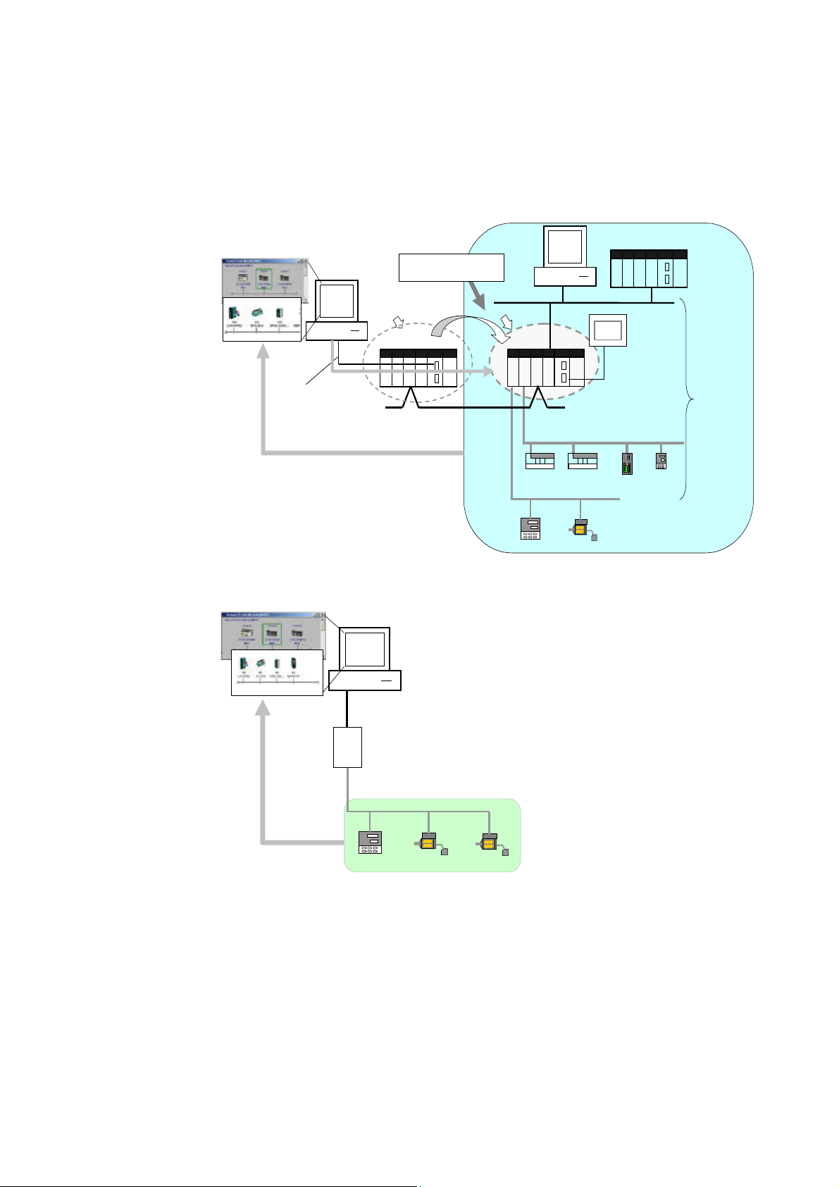
The network/serial communications configuration of a PLC other than the one originally
connected to online to can be set as the target. The PLC that was originally connected to
online (called the relay PLC, see note 1), is relayed through to connect to another PLC
(called the target PLC, see note 2) to switch the online connection.
Note 1: The relay PLC is the PLC to which an online connection was first made from the computer
through a network or serial connection.
Note 2: The target PLC is the PLC from which the network configuration can be uploaded.
Uploading and displaying network and serial
communications configuration of t he tar
network
Direct serial connection
(Toolbus or Host Link) or
network connection
et PLC for each
Computer running
CX-Integrator
Online
connection
Access
Uploaded to computer
A PLC other than the relay PLC
can be set as the target .
Relay PLC
CS/CJ-seri es PLC
Controller Link
Target PLC
CS/CJ-series
PLC
DeviceNe t
General-purpose slaves,
such as I/O Terminals
CompoWay/F
Ethernet
CS/CJ-seri es PLC
Serial connection
(NT Link)
PLC
Temperature
Controll er or
other device
Serial
communi cations /net
works that can be
accessed
Temperature
Controll er
Smart Sensor
Direction connection from the CX-Integrator to serial communications using the
CompoWay/F protocol is also possible using RS-232C or RS-485 communications without
going through a PLC. The CompoWay/F network configuration can also be uploaded.
Computer runnin g
CX-Integrator
Standard RS-232C cable (f emale-female)
K3SC RS-232C to RS-485 Interface
Converter
RS-485 cable connectio n
CompoWay/F protocol
Uploaded to computer
Temperature
Controller
Smart Sensor
Smart Sensor
1-3
Page 24

1-1 The CX-Integrator
1-1-2 Functions According to Network
1-1-2 Functions According to Network
The functions for each network are listed in the following table.
Network Functions
DeviceNet or CompoWay/F A virtual network or virtual serial communications
Controller Link or SYSMAC LINK User-set data link tables can be created offline
Controller Link A Controller Link Network Diagnostic Tool can be
Ethernet Broadcast node searches and ping tests are
NT Link Settings for an NS-series PT with a model number
FINS networks, such as Ethernet, Controller
Link, SYSMAC LINK, and DeviceNet
configuration can be created offline and connected
device parameters can be set, uploaded,
downloaded, and compared.
and then transferred online to CS/CJ-series PLCs.
Data link parameters can be set automatically
online and then transferred to CS/CJ-series PLCs.
started to diagnose Controller Link networks.
enabled (with CX-Integrator Ver. 1.1 or later).
ending in V1 or later serially connected to a
CS/CJ-series PLC via NT Link can be
automatically detected and set for the serial port of
the CS/CJ-series PLC. This is called NT Link Auto
Online Setting function.
Routing tables can be set offline and then
transferred online to CS/CJ-series PLCs.
Echoback tests between nodes are enabled (with
CX-Integrator Ver. 1.1 or later).
1-1-3 Connecting to the Relay PLC
Either of the following methods can be used to connect the CX-Integrator online to the relay
PLC.
Serial communications (Toolbus or Host Link Mode)
FINS network communications, such as Controller Link, SYSMAC LINK, Ethernet, Ethernet
FINS/TCP, or FinsGateway
Note: If the computer running the CX-Integrator is connected directly to a network, the network
address and node can be specified to set any PLC on the local network or an interconnected
network as the relay PLC.
1-4
Page 25

1-1-4 Accessible Network
The network configuration of the target PLC (i.e., either the relay PLC or a PLC connected to
the relay PLC) can be uploaded and monitored for each of the following networks.
Accessible Networks
Network Conditions
Ethernet Monitoring and editing parameters is possible for all CS/CJ-series PLCs
and NSJ-series NSJ Controllers on the Ethernet network. Only monitoring
the network configuration is possible for CVM1/CV-series PLCs and
computers with FinsGateway.
Controller Link Monitoring and editing parameters is possible for all CS/CJ-series PLCs
and NSJ-series NSJ Controllers on the Controller Link network. Only
monitoring the network configuration is possible for C200HX/HG/HS
PLCs, CVM1/CV-series PLCs, and computers with FinsGateway.
SYSMAC LINK Monitoring and editing parameters is possible for all CS-series PLCs on
the SYSMAC LINK network. Only monitoring the network configuration is
possible for C200HX/HG/HS PLCs, CVM1/CV-series PLCs, and
computers with FinsGateway.
DeviceNet Monitoring and editing parameters is possible for all CS/CJ-series
DeviceNet Units and NSJ-series NSJ Controllers. Only setting the
DeviceNet Master Unit is possible for C200H-series DeviceNet Master
Unit and CVM1/CV-series DeviceNet Master Units.
Accessible Serial Communications
Serial
communications
CompoWay/F The serial communications mode of the serial port must be Serial
Gateway Mode or Protocol Macro Mode. (See note.)
Note: To use the built-in serial ports on CS/CJ-series CPU Units,
unit version 3.0 or later must be used. For Serial Communications
Boards and Serial Communications Units, unit version 1.2 or later
must be used.
Monitoring and parameter editing is possible only for CompoWay/F slaves
for which CPS files have been installed on the computer running the
CX-Integrator.
(If the CompoWay/F slave is a Temperature Controller, however, only
monitoring the network configuration is possible. Parameters are edited
using the CX-Thermo.)
NT Link The serial communications mode of the serial port must be 1:N NT Link.
Monitoring is possible only for NS-series PTs with model numbers ending
in V1or later. (Monitoring is not possible for earlier NS-series PTs without
a model number suffix or for NT-series PTs.)
1-1 The CX-Integrator
1-1-4 Accessible Network
Conditions
1-5
Page 26

1-1 The CX-Integrator
1-1-4 Accessible Network
Local Network Table Requirements
A local network table must be registered in the target PLC in the following cases.
Communications Conditions
Network
communications
Serial
communications
Note: As an exception, local network tables are not required even when more than one Network
Communications Unit is mounted in the following situation:
Access is possible without a local network table when connecting online to the target PLC via a
direct serial connection and access is required only to the network of the Network
Communications Unit with the smallest unit number (set on the front panel rotary switches) of all
the Network Communications Units that are mounted to the target PLC.
• More than one Network Communications Unit is mounted to the target
PLC. (See note.)
Note: Network Communications Units include Ethernet Units, Controller
Link Units, SYSMAC LINK Units, DeviceNet Units, and FL-net Units.
Serial Communications Units and Serial Communications Boards are not
included except in the following case: If serial ports are registered in the
local network table to treat them as networks, the serial ports must be
treated as Network Communications Units, including the serial ports on
the CPU Unit.
• Routing tables are already registered in one or more nodes on the network.
• Communications are required between networks.
Serial ports on Serial Communications Units and Serial Communications
Boards are used as serial gateways to Host Link FINS and access is
required via networks via Host Link FINS to PLCs functioning as Host Link
slaves.
Note: Serial ports do not necessarily need to be registered in the local
network table (to treat them as networks) to enable using other serial
gateway functions. Registration is normally not required to convert from
serial to serial. Refer to 3-6 Overview of Serial Gateway Functions in the
CS/CJ-series Communications Commands Reference Manual (Cat. No.
W342) for details on whether local network tables are required to use
serial gateway functions.
1-6
Page 27
1-1-5 Communicating Across Network Layers
p
1-1-5 Communicating Across Network Layers
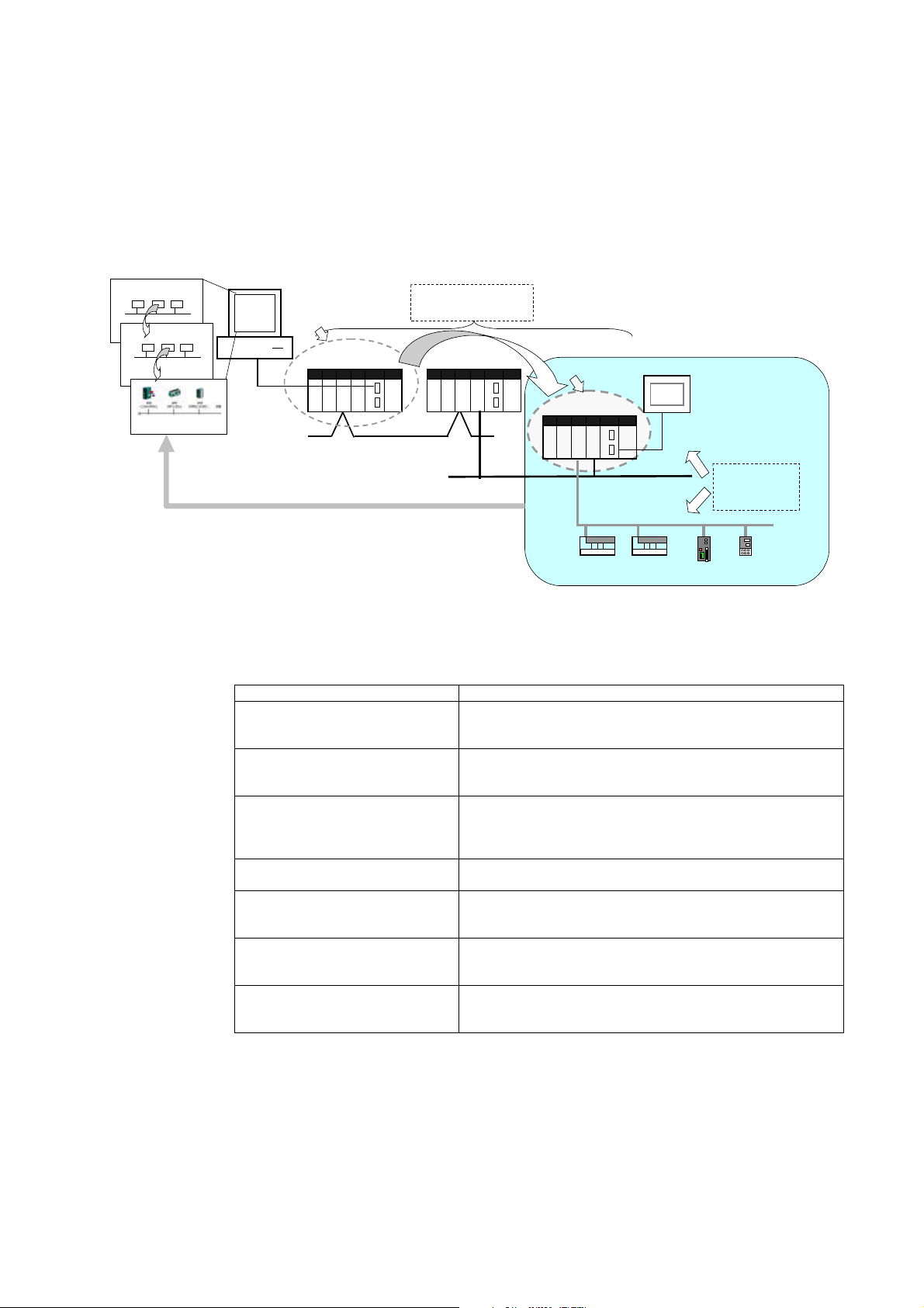
If relay network routing tables are set in the CPU Units of the PLCs, a PLC on a different
network layer than the network of the PLC connected to the CX-Integrator can be set as the
target PLC to enable uploading, saving, and comparing the network configuration of the
target PLC.
Uploading and displaying network and serial communications configurati on
of a target PLC on a remote network for each network
Computer running
CX-Integrator
Relay PLC
Relay network routing tables
set in the CPU Units
1-1 The CX-Integrator
CS/CJ-ser ies PLC
Controller Link
Serial connection
(Toolbus or Host
Link) or network
connection
Uploaded to computer
CS/CJ-series PLC
1-1-6 Starting Other Applications
The following applications can be started from the CX-Integrator.
Application Starting method
CX-Programmer Right-click the desired CS/CJ-series PLC in the Network
Configuration Window and select Start Special Application
from the pop-up menu.
Data Link Component Either select Tools – Start Data Link or right-click the desired
Routing Table Component Either select Tools – Start Routing table or right-click the
Controller Link Network Diagnostic
Tool
CX-Designer Right-click the desired NS-series PT in the Network
CX-Thermo Right-click the desired OMRON Temperature Controller in the
CX-Drive Right-click the desired Inverter or Servo in the Network
Controller Link Unit in the Online Connection Information
Window and select Start Data Link from the pop-up menu.
desired Communication Unit/port in the Online Connection
Information Window and select Start Routing table from the
pop-up menu.
Select Tools – Controller Link tool – Network diagnosis.
Configuration Window and select Start Special Application
from the pop-up menu.
Network Configuration Window and select Start Special
Application from the pop-up menu.
Configuration Window and select Start Special Application
from the pop-up menu.
Ethernet
Target PLC
CS/CJ-series PLC
General-purpose sl aves, such
as I/O Terminals
DeviceNet
Serial connection
(NT Link)
Network and serial
communications
structure can be
u
PLC
loaded.
Temperature
Controller or
other device
1-7
Page 28

1-2 Specifications
1-2-1 CX-Integrator Specifications
1-2 Specifications
1-2-1 CX-Integrator Specifications
Item Specification
Model Provided in the CX-One FA Integrated Tool Package (CXONE-AL@@C-E).
Setup media CD-ROM
Applicable
computers
(with
FinsGateway)
PLCs that can be used
as relay PLC for online
connections
Note: A relay PLC is the
PLC to which the
CX-Integrator is
connected online.
Computer IBM PC/AT or compatible
CPU Pentium II, 333 MHz or better, for Windows 98 SE or NT 4.0 with service pack 6a Pentium III, 1
GHz or better, is recommended.
OS Microsoft Windows 98 SE, Me, 2000, or XP
Microsoft Windows NT version 4.0 service pack 6a
Note: CX-Integrator cannot be used with Windows 95.
Memory 64 MB min. for Windows 98 SE or NT 4.0 with service pack 6a
Hard disk
drive
Monitor SVGA, 800 x 600 pixels or better
CD-ROM
drive
Communi
cations
port
100 MB min. of available space
Note: Use the small font size.
At least one required.
At least one RS-232C or USB port (See note.)
Note: The USB port on a computer can be connected to if the CJ1W-CIF31 USB-Serial
Conversion Cable is used. (The driver software included with the CJ1W-CIF31 must be installed
on the computer.)
Series Device type
CS Series
CJ Series
(See note 3.)
NSJ Series NSJ G5D (Used for the NSJ5-TQ0@-G5D, NSJ5-SQ0@-G5D,
(See note 1.)
CS1H CS1H-CPU67/66/65/64/63(-V1)
CS1G/CJ1G CS1G-CPU45/44/43/42(-V1)
CS1G-H CS1G-CPU45H/44H/43H/42H
CS1H-H CS1H-CPU67H/66H/65H/64H/63H
CS1D-H CS1D-CPU67H/65H (See note 2.)
CS1D-S CS1D-CPU67S/65S/44S/42S
CS1G/CJ1G CJ1G-CPU45/44
CJ1M CJ1M-CPU23/22/21/13/12/11
CJ1G-H CJ1G- CPU45H/44H/43H/42H
CJ1H-H CJ1H-CPU67H/66H/65H
CP1H-XA CP1H-XA@@@@-@ CP-Series
CP1H-X CP1H-X@@@@-@
NSJ8-TV0@-G5D, NSJ10-TV0@-G5D, and NSJ12-TS0@-G5D.)
CPU Unit model
Note 1: To connect the computer running CX-Integrator directly as a CompoWay/F slave, set
the Device type to CompoWay/F Device.
Note 2: When using a pre-Ver. 1.1 CS1D-H CPU Unit, use it as if it were a CS1H-H CPU
Unit.
Note 3: Use commercially available USB cable (B type to A type connectors) for connecting
CP-series CPU Units.
1-8
Page 29

Item Specification
Connecting to the
Relay PLC
Either of the following can be used.
Serial
communications
FINS network
communications
Direction connection is possible to any of the following serial ports on a
CS/CJ-series PLC.
• CPU Unit peripheral port (Toolbus or Host Link)
• CPU Unit RS-232C port (Toolbus or Host Link)
• CPU Unit USB port (CP Series only)
• Serial Communications Board or Serial Communications Unit RS-232C
port or RS-422A/485 port (Host Link)
Direct connection is possible to any of the following serial ports on an
NSJ-series NSJ Controller.
• RS-232C port A (Toolbus) on NSJ Controller
• RS-232C port B (Toolbus) on NSJ Controller
• USB port on NSJ Controller
Note: Automatic online connection is possible for serial communications
ports. (The user does not have to set the computer communications
settings.) The communications settings will be automatically set to
those of the PLC. Connection is possible to a serial port on the CPU
Unit, a Serial Communications Board, or a Serial Communications
Unit. For PLC serial ports, however, only the Toolbus or Host Link
serial communications modes can be used and the baud rate must be
9600, 19200, 38400, or 115200 bits/s.
Direction connection is possible through any of the following networks on
a CS/CJ-series PLC or NSJ-series NSJ Controller.
• Ethernet (Ethernet, Ethernet FINS/TCP, or FinsGateway)
• Controller Link (Controller Link or FinsGateway)
• SYSMAC LINK (SYSMAC LINK or FinsGateway)
1-2 Specifications
1-2-1 CX-Integrator Specifications
1-9
Page 30

1-2 Specifications
1-2-1 CX-Integrator Specifications
Item Specification
PLCs that are
accessible as target
PLCs
Note: The target PLC
is the PLC actually
being accessed, e.g.,
to upload/download
the PLC’s network
configurations.
Supported
communications
Series Device type CPU Unit model
CS Series
CJ Series
NSJ
Series
Note: The CS/CJ-series PLC must have a lot number of 030201 or later (manufactured 1
The following communications are possible for a directly connected target PLC.
Supported network
communications
Supported serial
communications
Note: Accessing PLC Communications Across Network Layers
If relay network routing tables are set, a PLC on a different network layer than the network of the
PLC connected to the CX-Integrator can be set as the target PLC.
CS1H CS1H-CPU67/66/65/64/63(-V1)
CS1G/CJ1G CS1G-CPU45/44/43/42(-V1)
CS1G-H CS1G-CPU45H/44H/43H/42H
CS1H-H CS1H-CPU67H/66H/65H/64H/63H
CS1D-H CS1D-CPU67H/65H
CS1D-S CS1D-CPU67S/65S/44S/42S
CS1G/CJ1G CJ1G-CPU45/44
CJ1M CJ1M-CPU23/22/21/13/12/11
CJ1G-H CJ1G- CPU45H/44H/43H/42H
CJ1H-H CJ1H-CPU67H/66H/65H
CP1H-XA CP1H-XA@@@@-@ CP-Series
CP1H-X CP1H-X@@@@-@
NSJ G5D (Used for the NSJ5-TQ0@-G5D,
February 2003 or later) to start the CX-Designer and transfer screen data to an NS-series PT
from the CX-Designer through the PLC. The following PLCs can be used:
CS1G-H, CS1H-H, CS1D-S, CJ1M, or CJ1H-H. (The CS1D-H cannot be used.)
Note: CompoWay/F cannot be
used with a built-in serial
port on the CPU Unit.
Note: A CPU Unit with unit
version 3.0 or later must be
used when using
CompoWay/F with a
built-in serial port on the
CPU Unit
Note: CompoWay/F cannot be
Note: When using a pre-Ver. 1.1
CS1D-H CPU Unit, use it as if it
were a CS1H-H CPU Unit.
NSJ5-SQ0@-G5D, NSJ8-TV0@-G5D,
NSJ10-TV0@-G5D, and
NSJ12-TS0@-G5D.)
Ethernet (Access is possible only to CS/CJ-series PLCs, NS-series PTs,
and computers with FinsGateway on the Ethernet network. For
CVM1/CV-series PLCs, only display functions are supported.)
Controller Link (Access is possible only to CS/CJ/CP-series PLCs,
NS-series PTs, and computers with FinsGateway on the Controller Link
network.) For C200H-series PLCs and CVM1/CV-series PLCs, only
display functions are supported.)
Note: When the Controller Link Network Diagnosis application is
being used, it is possible to monitor and troubleshoot PLC models in
the Controller Link network other than CS/CJ-series PLCs.
SYSMAC LINK (Monitoring is possible only to CS/CJ-series PLCs,
NS-series PTs, and computers with FinsGateway on the SYSMAC LINK
network.)
DeviceNet (CS/CJ-series DeviceNet Units, C200H DeviceNet Master
Units, or CVM1/CV-series DeviceNet Master Units)
Note: A C200H-DRM21-V1 or CVM1-DRM21-V1 DeviceNet Master
Unit can be used through a CS/CJ-series DeviceNet Unit.
CompoWay/F (CS/CJ-series CPU Units must be unit version 3.0 or later.)
Serial Communications Boards and Serial Communications Units must be
unit version 1.2 or later. Only slaves for which CPS files are installed on
the computer can be accessed.
NT Links (Connection is possible only for NS-series PTs with model
numbers ending in V1 or later.)
used with a built-in serial
port on the CPU Unit.
Note: A CPU Unit with unit
version 3.0 or later must
be used when using
CompoWay/F with a
built-in serial port on the
CPU Unit
Note: CompoWay/F cannot be
used with a built-in USB
port on the CPU Unit. It
can be used with a serial
communications port.
Note: CompoWay/F can be used
on serial port C (RS-232C
port) on the Controller
Section of the NSJ
Controller.
1-10
Page 31

1-2-1 CX-Integrator Specifications
Item Specification
Online Connection
Information Window
Communications
monitoring functions
Setting functions
Verification functions Verifying communications/network configurations
Operations The following operations are possible for the CPU Unit at the target PLC.
When the target PLC is online, Communications Units connected to the target PLC (referred to here
as simple “Communications Units”) are displayed as follows:.
Target Device, Target PLC CPU Unit model (network address) (node address)
• CPU Unit name [model] (network address) (-) (serial port FINS unit address)
• Communications Unit name [model] (network address) (node address) (unit number)
• Communications Unit name [model] (network address) (node address) (unit number)
Communications configuration information can be uploaded by right-clicking a Communications Unit
and selecting Transfer – Network to PC.
Ethernet Node information for FINS communications (CPU Unit model, Ethernet
Unit mode, node address, and network address)
Controller Link Information on nodes participating in the Controller Link network (CPU
SYSMAC LINK Information on nodes participating in the SYSMAC LINK network (CPU
DeviceNet Information on nodes connected to DeviceNet for which EDS files are
CompoWay/F Information on nodes connected to a serial port in serial gateway mode or
NT Link Information on nodes connected to 1:N NT Links (NS-series PT model
Ethernet Ethernet Unit settings (CPU Bus Unit System Settings)
Controller Link
SYSMAC LINK
DeviceNet DeviceNet Unit master parameters (remote I/O allocations, connection
CompoWay/F CompoWay/F slave parameters (except for Temperature Controllers)
NT Link None
FINS networks, such
as Ethernet, Controller
Link, SYSMAC LINK,
and DeviceNet
Verifying component parameters
Creating, editing, and transferring I/O tables
Displaying current errors and error logs
Changing the operating mode
Transferring or verifying a manually set data link table
Transferring or verifying a routing table (FINS local routing table)
Unit model, Controller Link Unit mode, node address, and network
address)
The following functions are also possible if the Controller Link Network
Diagnostic Tool is started.
Configuration node diagnosis (network participation status, current
Controller Link Unit errors, current CPU Unit errors, and differences from
node files), setting diagnosis (e.g., DM Area parameter setting
consistency), line disconnection information diagnosis, transmission
status diagnosis, node status (displaying current error status and error
log), error log collection, and node file editing (node names, connection
order, and Repeater Units)
Unit model, Controller Link Unit mode, node address, and network
address)
installed on the computer (DeviceNet Unit model, slave model,
master/slave node addresses)
protocol macro mode for which CPS files are installed on the computer
(CompoWay/F SLAVE model and CompoWay/F node address).
Note: CS/CJ-series CPU Units with unit version 3.0 or later, or Serial
Communications Boards/Units with unit version 1.2 or later, or
CP-series Communications Option Boards must be used.
and NT Link unit number)
Note: Automatic detection of NS-series PTs connected serially to a
CS/CJ-series PLC is also possible. (The NT Link Automatic Setting
Function automatically changes the setting of the PLC’s serial port to
match those of the NS-series PT.)
User-set data link tables
Controller Link and SYSMAC LINK Unit settings (in allocated DM Area
words), including automatically set data link parameters (transferred to
the startup node set as the target PLC)
settings, device information check, communications cycle time, etc.)
Slave parameters
Note: Parameters for CompoWay/F-compatible Temperature Controllers
are set using the CX-Thermo, started as an application.
PLC serial port communications settings (CPU Unit: part of PLC Setup,
Serial Communications Boards/Units: allocated DM Area words)
Routing tables (FINS local routing tables and FINS network routing
tables)
Note: The FINS local routing table is transferred to the target PLC.
1-2 Specifications
1-11
Page 32

1-2 Specifications
1-2-2 Files Created by the CX-Integrator
1-2-2 Files Created by the CX-Integrator
The following files can be created by the CX-Integrator.
Files Contents Details
Project files (.cin) Connection
information to relay
PLC, all network
configurations for
target PLC, and
parameters for
DeviceNet masters,
DeviceNet slaves,
and CompoWay/F
slaves
Network
configuration files
Component
parameter files
Data link table files
DeviceNet network
structure files (.npf)
Controller Link node
files (.crg)
DeviceNet device
parameter files
(.dvf)
CompoWay/F
component
parameter files
(.xml)
Controller Link data
link table files (.cl2)
SYSMAC LINK data
link table files (.sl3)
These files are used offline to check network configurations and parameters
and for other purposes, such as printing. Each file consists of the following:
Device type setting information of the relay PLC
Communications Unit models connected to the target PLC (Ethernet Units,
Controller Link Units, SYSMAC LINK Units, DeviceNet Units, and Serial
Communications Boards/Units)
Device models connected to the above CPU Units or Communications
Units via communications (DeviceNet slaves, CompoWay/F slaves,
NS-series PTs, etc.)
Parameters for DeviceNet Master Unit and Device parameters and
DeviceNet slaves (for all devices for which EDS files are installed on the
computer including slaves from other manufacturers)
Parameters for CompoWay/F slaves (for all components for which CPS
files are installed on the computer (except for Temperature Controllers)
Controller Link network parameters
Controller Link and SYSMAC LINK Unit allocated DM Area words settings,
including automatically set data link parameters
Ethernet Unit CPU Bus Unit System Settings
Serial Communications Board/Unit serial communications settings
Note: Routing tables (local network tables and relay network tables) and
user-set data link tables are not included in project files.
Network configuration for one DeviceNet network connected directly to the
target PLC (including master and slave parameters)
Note: These are the same as the DeviceNet network structure files (.npf)
created with DeviceNet Configurator version 2.@. Files created with
DeviceNet Configurator version 2.@ can be imported/exported.
Network configuration for Controller Link networks connected directly to the
target PLC
Parameters for individual DeviceNet devices (master or slave)
Note: These are the same as the DeviceNet device parameter files (.dvf)
created with DeviceNet Configurator version 2.@. Files created with
DeviceNet Configurator version 2.@ can be imported.
Parameters for individual CompoWay/F slaves (except for Temperature
Controllers)
CPU Unit parameters (parts of PLC Setup: serial communications settings)
Controller Link or SYSMAC LINK network parameters
Controller Link and SYSMAC LINK Unit allocated DM Area words settings,
including automatically set data link parameters
Ethernet Unit CPU Bus Unit System Settings
Serial Communications Board/Unit serial communications settings
Controller Link user-set data link tables
Note: These are the same as the Controller Link data link table files (.cl3)
created with the CX-Net. Files created with the CX-Net can be
imported.
SYSMAC LINK user-set data link tables
Note: These are the same as the SYSMAC LINK data link table files (.sl3)
created with the CX-Net. Files created with the CX-Net can be
imported.
1-12
Page 33

File name Contents Details
Routing table files
FINS local routing
table files (.rtg)
FINS network
routing table files
(.rt3)
Routing tables of the target PLC
Note: These are the same as the FINS local routing table files (.rtg) created
with the CX-Net. Files created with the CX-Net can be imported.
Routing tables for all PLCs on networks to which the target PLC belongs
Note: These are the same as the FINS network routing table files (.rt3)
created with the CX-Net. Files created with the CX-Net can be
imported.
Note With DeviceNet only, the following files can also be exported and saved.
EDS files (.eds)
The device list saved in CSV format (.csv)
The I/O comments saved in CSV format (.csv)
The device parameters of an OMRON DeviceNet Master Unit saved as an Open
Network Controller DRM_UNIT (virtual unit) file
The device parameters of an OMRON DeviceNet Master Unit saved as a NetX Server
(NetX Server for DeviceNet) file
Note The CX-Integrator does not support files created in the DeviceNet Configurator Ver.
1.0 file format.
1-2 Specifications
1-2-2 Files Created by the CX-Integrator
1-13
Page 34

1-3 Installation
1-2-2 Files Created by the CX-Integrator
1-3 Installation
The CX-Integrator is installed from the CX-One Installer. Refer to the CX-One Setup Manual
(W444) for details.
1-14
Page 35

1-4-1 Direct Serial Connections to a PLC
1-4 PLC Connecting Cables
1-4-1 Direct Serial Connections to a PLC
When connecting the computer running the CX-Integrator directly to a PLC using a serial
line, make the connection correctly using the following Connecting Cables and connection
diagrams.
Connecting Cables to CS/CJ-series PLCs
Unit Unit port Computer
CPU Unit
Built-in
peripheral port
IBM PC/AT
or
Computer
port
D-sub
9-pin male
compatible
Built-in
RS-232C port
D-sub 9-pin
IBM PC/AT
or
compatible
D-sub
9-pin male
male
Serial
Communications
Boards/Units
RS-232C port
D-sub 9-pin
male
IBM PC/AT
or
compatible
Host Link
Refer to the following connection diagrams.
Connection to IBM PC/AT or Compatible
Connection to Peripheral Por t
IBM PC/AT or compatibl e
Connection to RS-232C Port
IBM PC/AT or compatibl e
Network type
(serial
communications
mode)
Peripheral bus
(Toolbus)
or Host Link
(SYSWAY)
Peripheral bus
(Toolbus)
or Host Link
(SYSWAY)
Host Link
(SYSWAY)
(SYSWAY)
1-4 PLC Connecting Cables
Model Length Remarks
CS1W-CN226/626 2 m/6 m ---
XW2Z-200S-CV/
500S-CV
XW2Z-200S-V/
500S-V
XW2Z-200S-CV/
500S-CV
XW2Z-200S-V/
500S-V
2 m/5 m Connector
with ESD
(electrostatic
discharge)
countermeasu
res used.
2 m/5 m ---
2 m/5 m Connector
with ESD
(electrostatic
discharge)
countermeasu
res used.
2 m/5 m -
9-pin
CS1W-CN2 26 (2.0 m)
CS1W-CN6 26 (6.0 m)
CPU Unit peripheral port
9-pin
XW2Z-200S-CV (2.0 m)
XW2Z-500S-CV (5.0 m)
9-pin
Built-in RS-232C
port on CPU Unit
or port on Serial
Communications
Board/Unit
Note
•When using an RS-232C cable for the computer running CX-Integrator and
connecting to a CS/CJ-series PLC with a Toolbus connection, use a
XW2Z-200S-CV/500S-CV Connecting Cable. (This cable can be used only with IBM
PC/AT or compatible computers.)
•The following connection methods can be used when connecting an RS-232C cable
to a peripheral port on a CS/CJ-series PLC.
1-15
Page 36

1-4 PLC Connecting Cables
p
p
1-4-1 Direct Serial Connections to a PLC
Unit Unit port Computer
CPU Unit Built-in
peripheral port
IBM
IBM
PC/AT or
compatible
PC/AT or
compatible
Connection to
RS-232C Port
XW2 Z-@@@S-@@
RS-232C cable
(listed above)
Computer
D-sub 9-pin
male
D-sub 9-pin
male
port
Network type
(serial
communications
mode)
Peripheral bus
(Toolbus)
or Host Link
(SYSWAY)
Host Link
(SYSWAY)
Model Length Remarks
CS1W-CN118 +
XW2Z-200S-CV/
500S-CV
CS1W-CN118 +
XW2Z-200S-V/
500S-V
0.1 m +
2 m/5 m
0.1 m +
2 m/5 m
The
XW2Z-@@@
S-CV uses a
connector
with ESD
(electrostatic
discharge)
countermeas
ures.
---
Peri
heral port
CS1W-CN118
Note The following connection methods can be used when connecting an CQM1-CIF01/02
cable to a peripheral port on a CS/CJ-series PLC.
Unit Unit port Computer
CPU Unit Built-in peripheral
port
IBM
PC/AT or
compatible
Computer
port
D-sub 9-pin
male
Network type
(serial
communications
mode)
Host Link
(SYSWAY)
Note: Baud rate
must be 19.2
Kbits/s or less.
Model Length Remarks
CS1W-CN114 +
CQM1-CIF02
05 m +
3.3 m
---
Connection to
RS-232C Port
CQM1-CIF01/02
Peripheral Cable
CS1W-CN114
Peri
heral port
1-16
Page 37

Note Connecting the PLC Using a USB Port on the Computer
Computer
running
CX-Integrator
1-4 PLC Connecting Cables
1-4-1 Direct Serial Connections to a PLC
A USB port on the computer can be used to connect the computer running the
CX-Integrator to a PLC. To do so, connect the computer to the PLC as shown below
using a CS1W-CIF31 USB-Serial Conversion Cable. When connecting the computer to
a CP-series PLC, it is possible to make a direct connection using a
commercially-available USB cable (B type – A type connectors).
The driver software included with the CJ1W-CIF31 must be installed on the computer
to use a USB port to connect the CX-Integrator. Refer to the PDF User’s Manual
included with the CS1W-CIF31 USB-Serial Conversion Cable for details.
PLC Connection Methods
CS1W-CIF31 Cable 1
CS1W-N226/626 CS/CJ-series
Peripheral Port Programming
Device Connecting Cable
or
CS1W-CIF31
USB Connecting Cable
+
CQM1H-CIF02 C-series
Peripheral Port Programming
Device Connecting Cable
+
or
@@@
XW2Z-
RS-232C Programming
Device Connecting Cable
Cable 2
(when required)
CS1W-CN114
C-series-CS/CJ-series
Peripheral Conversion Cable
CS1W-CN118
RS-232C-CS/CJ-series
Peripheral Conversion Cable
PLC
CS/CJ-series CPU Unit Connection Patterns
USB
Connecting
Cable
Model Connector Model Connector Connector Model Connector
CS1W-CIF31
D-sub 9-pin
female
D-sub 9-pin
female
D-sub 9-pin
female
D-sub 9-pin
female
D-sub 9-pin
female
D-sub 9-pin
female
Cable 1
CS1W-CN226/626
(length: 2 m/6 m)
CQM1-CIF02
(length: 3.3 m)
XW2Z-200S-CV
/500S-CV
(length: 2 m/5 m)
XW2Z-200S-V
/500S-V
(length: 2 m/5 m)
XW2Z-200S-CV
/500S-CV
(length: 2 m/5 m)
XW2Z-200S-V
/500S-V
(length: 2 m/5 m)
CS/CJ
peripheral
C peripheral C peripheral CS1W-CN114
D-sub 9-pin
male
D-sub 9-pin
male
RS-232C
D-sub 9-pin
male
RS-232C
D-sub 9-pin
male
D-sub 9-pin
female
D-sub 9-pin
female
Cable 2
Not needed.
(length: 5 cm)
CS1W-CN118
(length: 0.1 m)
CS1W-CN118
(length: 0.1 m)
Not needed.
Not needed.
CS/CJ
peripheral
CS/CJ
peripheral
CS/CJ
peripheral
Port Serial
communications
CS/CJ
peripheral
RS-232C
D-sub 9-pin
female
mode
(network
type)
Peripheral
(Toolbus)
or Host Link
(SYSWAY)
Host Link
(SYSWAY)
Peripheral
(Toolbus)
or Host Link
(SYSWAY)
Host Link
(SYSWAY)
Peripheral
(Toolbus)
or Host Link
(SYSWAY)
Host Link
(SYSWAY)
1-17
Page 38

1-4 PLC Connecting Cables
1-4-1 Direct Serial Connections to a PLC
Connection diagrams are shown below.
Connecting to the Peripheral Port
-Using the CS1W-CN226/626 Connecting Cable
USB A-plug connector,
male
CS1W-CIF31
D-sub connector
(9-pin male)
D-sub connector
(9-pin female)
Recommended cable:
CS1W-CN226/6 26
-Using the CQM1-CIF02 Connecting Cable
●
●
CS/CJ peripheral connector
CS/CJ-series PLCs
Customizable Counter Units
Peripheral port
USB A-plug connector,
male
CS1W-CIF31
D-sub connector
(9-pin male)
D-sub connector
(9-pin female)
Recommended cable:
CQM1-CIF02
C peripheral connector
●
CS/CJ-series PLCs (See note.)
CS1W-CN114
CS/CJ peripheral connector
Peripheral p ort
Note: Only a Host Link connection is possible for CS/CJ-series PLCs.
1-18
Page 39

1-4 PLC Connecting Cables
1-4-1 Direct Serial Connections to a PLC
-Using the XW2Z-200S-CV/500S-CV or XW2Z-200S-V/500S-V Connecting Cable for
RS-232C
USB A-plug connector,
male
CS1W-CIF31
D-sub connector
(9-pin male)
CS/CJ peripheral
connector
Peripheral port
D-sub connector
(9-pin female)
XW2Z-200S-CV/500S-CV
XW2Z-200S-V/500S-V (See note.)
or
CS/CJ-series PLCs
D-sub connector (9-pin male)
D-sub connector
(9-pin female)
CS1W-CN118
Note: Only a Host Link connection is possible for CS/CJ-series PLCs.
-Using the XW2Z-200S-CV/500S-CV or XW2Z-200S-V/500S-V Connecting Cable for
RS-232C
USB A-plug connector,
male
CS1W-CIF31
D-sub connector
(9-pin male)
D-sub connector
(9-pin female)
CS/CJ-series PLCs
D-sub connector
(9-pin male)
RS-232C port
D-sub connector
(9-pin female)
Recommended cable:
XW2Z-200S-CV/500S-CV
or
XW2Z-200S-V/500S-V (See note.)
Note: Only a Host Link connection is possible for CS/CJ-series PLCs.
1-19
Page 40

1-4 PLC Connecting Cables
1-4-1 Direct Serial Connections to a PLC
Connecting Cables for CP1H-series PLCs
Connecting to USB Port in CPU Unit Using Commercially-available USB Cable
Unit Port at
Unit
CPU Unit USB port
(B
connector)
USB port
Commerciallyavailable USB
cable
Peripheral USB port
Computer Port at
computer
DOS/V USB port
(A
connector)
DOS/V computer
CP1H CPU Unit
Network type
Model Length Remarks
(serial
communications
mode)
USB Cable
for USB
1.1 or
2.0
Connecting by RS-232C Cable to the RS-232C Port in a Serial Communications
Option Board
Unit Unit port Computer Computer
CP1WCIF01
Serial
Option
Board
RS-232C
port, D-SUB
9-pin,
female
IBM
PC/AT or
compatible
port
D-SUB
9-pin, male
Network type
(serial
communications
mode)
Host Link
(SYSWAY)
Model Length Remarks
XW2Z200S-CV/
500S-CV
2 m/
5 m
5 m max.
Connect
or with
ESD
(electrostatic discharge)
counterm
easure
used.
---
1-20
Page 41

1-4 PLC Connecting Cables
1-4-2 Direct Connections to a Relay PLC via a Network
1-4-2 Direct Connections to a Relay PLC via a Network
When connecting the computer running the CX-Integrator directly to the relay PLC via a
network, make the connection correctly using the following connection diagrams.
Ethernet
CS/CJ-series
Ethernet Unit
Ethernet port
CS/CJ-series
relay PLC
Ethernet
DeviceNet network
Controller Link or SYSMAC LINK
PCI Controller Link Support Board
(See note.)
Controller Link
Note:
Optical ring with H-PCF cable 3G8F7-CLK12-V1
Optical ring with GI cable 3G8F7-CLK52-V1
Wired (twisted-pair cable)
Type Board Model
CS/CJ-series
Controller Link Unit
Controller Link PCI-bus
Support Board
CS/CJ-series
relay PLC
DeviceNet network
3G8F7-CLK21-V1
1-21
Page 42

1-5 Window Descriptions
1-5-1 Starting Methods
1-5 Window Descriptions
1-5-1 Starting Methods
The CX-Integrator can be started with any of the following three methods.
1) When using the CX-Programmer Ver. 6.0 or later, select Tools
2) When using the CX-Programmer that was installed from the CX-One, right-click a
Communication Unit in the CX-Programmer’s I/O table display and select Start Special
Application from the pop-up menu.
Note: If the Communication Unit is a Serial Communications Board/Unit, a Start Special Application
Dialog Box will be displayed. Select CX-Integrator in the dialog box to start the CX-Integrator.
3) Select CX-Integrator from the Start Menu.
1-5-2 Main Window
One of the following windows will appear when the CX-Integrator is started.
Offline Window
−
Network Settings.
Workspace Window
Online Window
Workspace Window
Online Conn ection
Information Window
Network Configuration Window
Network Configuration Window
Output Wind ow
1-22
Page 43

1-5 Window Descriptions
=
1-5-2 Main Window
Note The following operations can be performed on the Workspace Window, Output
Window, Component List Window, and Outline Window.
Moving a Window and Displaying the Window Separately
Drag the window by its top border to move it.
Closing a Window
Click the X Button (Close Button) at the upper-right corner of the window.
Displaying a Window
−
Select the desired window from the View
next to the windows that are displayed.)
Windows Menu. (A check mark appears
Online Connection Information Window
The Online Connection Information Window displays the online/offline status and the Relay
PLC’s communications settings.
When online, the target PLC will be displayed in a tree structure with all of the
Communications Units and ports that belong to it.
Online Operation
The target PLC and Communication Units/ports mounted to the target PLC will be listed
below the relay PLC.
Relay PLC Communications Settings
The relay PLC’s communications settings will be displayed to the right of the Online icon
Online).
(
Relay PLC
Target PLC
Target PLC Information
The target PLC’s CPU Unit model, Net (network address), and Node (node address) will be
displayed to the right of the Target icon (
Display format: Target PLC [Target PLC’s CPU Unit model] Net (network address) Node (node address)
Description:
In brackets
[ ] to the right of
TargetPLC
Target PLC’s
CPU Unit model
[Target PLC’s CPU Unit
Target PLC’s CPU Unit
model
After Connecting Online
The target PLC is displayed in green.
model]
When the computer is directly
connected to a PLC, the same
PLC will be both the relay PLC
and the target PLC.
Target PLC).
Net (Network address) Node (Node address)
Network address (1 to 127,
decimal)
Note: This is the network
address registered when this
PLC is registered as the target
PLC via the relay PLC.
Node address (decimal)
Note: This is the node
address on the network
registered when this PLC
is registered as the target
PLC via the relay PLC.
1-23
Page 44

1-5 Window Descriptions
1-5-2 Main Window
Communications Unit and Port Information for Target PLC
The following CPU Unit built-in serial ports, Inner Boards, and Communications Units
(referred to here as Communications Units/Ports) that are part of the target PLC are
displayed under TargetPLC in directory tree format.
Display format:
FINS unit address)
Description:
Communications
Unit/port
CPU Unit built-in
serial port
Serial port on
Inner Board
(Nothing
displayed if an
Inner Board is not
mounted.)
Communications
Unit name, Model
Right of or :
Unit name
CPU Unit/port Target PLC’s
Serial Communications
Board
Communications Unit
name (Ethernet Unit,
Controller Link Unit,
SYSMAC LINK Unit, or
DeviceNet Unit)
If a connection is established and access is enabled for a Communications Unit/port, the
icon on the left will be
Right-click the Communications Unit/port and select Connect to connect to the
Communications Unit/port and enable access. (With the CX-Integrator, only one
Communications Unit/port can be accessed at any one time.)
The actual network configuration can then be uploaded by right-clicking the Communications
Unit/port and selecting Transfer
Unit name [Unit model] Net (network address) Node (node address) Unit (unit number or
or
: Not connected (access not possible).
: Connected (access possible).
[Unit model]
CPU Unit
model
Serial Communications
Board model
Communications Unit
model
Net (Network
address)
The network address
(1 to 127, decimal),
when the serial port is
registered in the local
network table to treat
it as a network.
Note: “−” will be
displayed if the serial
port is not registered
in the local network
table.
Same as above. − (Does not
Network address (1 to
127, decimal)
Note: “−” will be
displayed if a local
network table is not
registered.
Node (Node
address)
− (Does not
change.)
change.)
Node
address
(node ID on
the network)
Unit (Unit number
Serial port’s FINS
unit address
(decimal)
Peripheral port: 253
RS-232C port: 252
Note: “−” will be
displayed if the
serial port is not
registered in the
local network table.
Serial port’s FINS
unit address
(decimal)
Port 1: 225
Port 2: 226
Note: “−” will be
displayed if the
serial port is not
registered in the
local network table.
Unit number
(decimal)
(Rotary switch on
front of CPU Bus
Unit: 0 to 15)
instead of .
−
Network to PC.
or FINS unit
address)
1-24
Page 45

1-5 Window Descriptions
1-5-2 Main Window
Online Connec tion
Information W indow
Target PLC displayed in green.
Note: If an onl ine connection is
made to the rel ay PLC, the relay
PLC will also b e the target PLC
by default.
The
the Communic at ion Unit/port that is
presently conn ected and accessible.
Note CX-Integrator Communications Connections
Network Type
COM Port No., Baud Rate, Parity, Data
Bits, Stop Bits
Relay PLC’s CPU Unit model
Online
displayed.
icon will be displayed next to
Unit No.
Node Address
Network Address
Communications Unit model (CPU Unit model for C PU Unit built-in serial por ts)
Communications Unit name (CPU Unit for CPU Un it built-in serial ports)
Relay PLC’s FINS destinat ion network
address
Relay PLC’s FI NS destination node
address
Target PLC’s CPU Uni t model
Target PLC’s net work address
Target PLC’s node address
Communicati ons Unit and port inform ation
for target P LC
Displayed from the top in the following order.
•
CPU ports: CPU Unit ser ial ports
• Inner Boards ( Nothing is displaye d if no
Inner Boards are m ounted.)
• Communications Units
Note: If an online connection is made to the relay PLC, that PLC will be both the relay PLC and the
target PLC. The Communications Units mounted in the relay PLC will be displayed in the Online
Connection Information Window. Normally, the CX-Integrator is used with the same PLC as both
the relay PLC and the target PLC.
Once a connection has been made, it is possible to download the network configuration and
switch the target PLC to any PLC on the network. To do this, right-click a PLC on a network and
select Connect to this PLC.
There are three levels of CX-Integrator communications connections depending on
where the connection is made.
Relay PLC
communication s
settings
Target PLC
information
1-25
Page 46

1-5 Window Descriptions
1-5-2 Main Window
Display in Online
Connection
Information
Window
1) Online connection to
the relay PLC
Online
2) Status Online
connection to the
target PLC
TargetPLC or
TargetComponent
(See note.)
3) A connection to one
of the Communications
Units/ports at the
target PLC (Access is
possible.)
Note:To connect the computer (CX-Integrator) directly to a CompoWay/F Slave through a serial
connection, select CompoWay/F Device as the PLC model.
Offline Displays
Level Operation Remarks
Right-click the
communications settings
for the relay PLC and
select Auto Online or
Remember that this icon
indicates that the online
connection is to the relay
PLC.
Work Online.
The operation is the same
as above when the relay
PLC is the target PLC.
If the target PLC is
different from the relay
PLC, upload the
communications
configuration, right-click
the target PLC, and select
Connect to this PLC.
An online connection to the
target PLC is made after
connecting online to the relay
PLC, as described above.
The following operations are
possible for the CPU Unit at
the target PLC.
I/O tables: Creating, editing,
and transferring I/O tables
Error log: Displaying current
errors and error logs
Mode setting: Changing the
operating mode
Right-click the
Communications Unit/port
and select Connect.
Only one Communications
Unit/port can be accessed at
any one time.
Communications
configurations can be
uploaded only for a
Communications Unit/port in
this status.
Note: Access is possible to a
Communications Unit/port
only when it is connected.
Access is not possible when
disconnected.
Online Connectio n
Information Wi ndow
Relay PLC Communications Settings
Network Type
COM Port No., Ba ud Rate, Pari ty, Data
Bits, Stop Bits
Offline displayed.
Relay PLC’s CPU Unit
Relay PLC’s FINS dest ination network addres s
Relay PLC’s FINS dest ination node
Relay PLC
communications
settings
1-26
Page 47

1-5 Window Descriptions
1-5-2 Main Window
Relay PLC Communications Settings
Display format: Offline, Network Type, COM Port No., Baud Rate, Parity, Data Bits, Stop Bits
[relay PLC’s CPU Unit model] Net (Network Address) Node (Node Address)
Description:
Display item Network Type
Contents The following network
Example Toolbus COM1, 19200, None, 8, 1
types will be displayed for
the connection to the
relay PLC.
Toolbus (peripheral)
SYSMAC WAY (Host
Link)
SYSMAC LINK
Ethernet
Ethernet (FINS/TCP)
FinsGateway
Controller Link
Display item
Example [CS1H-CPU67H] Net (0) Node (0)
Contents Relay PLC’s CPU Unit
Relay PLC’s CPU Unit
model
model
Updating the Online Connection Information Window Display
This section describes how to update the target PLC display in the Online Connection
Information Window display, and how to display the updated information.
COM Port
No.
COM port on
computer
Relay PLC’s FINS destination
network address (decimal)
For a direct serial connection, the FINS destination network and node addresses
are normally displayed as 0.
For direct network connections, any FINS destination network (1 to 127) and
node addresses can be set. (If routing tables are registered in the PLCs on the
networks, specifying a PLC on any network other than the network that is
directly connected to is also possible.
Baud Rate Parity Data Bits Stop Bits
(Displayed
only for
Toolbus or
SYSMAC
WAY)
Baud rate is
displayed in
bits/s.
(Displayed
only for
SYSMAC
WAY)
The
communicatio
ns data
format parity
is displayed.
Even, Odd, or
None
Relay PLC’s FINS destination node
(Displayed
only for
SYSMAC
WAY)
7 or 8
address (decimal)
(Displayed
only for
SYSMAC
WAY)
1 or 2
!Caution When changing or removing a routing table (see note), be sure to update the
display for the Online Connection Information Window. The display for the
Online Connection Information Window could possibly be different from the actual network status. If operations are executed without first updating the display,
particularly online operations in the Network Configuration Window, it could
cause data to be mistakenly read or written for the wrong network or node address or unit number.
Note: Changing or removing a routing table refers to using the CX-Integrator (or a
CX-Integrator for another personal computer) to start the Routing Table
Component and then changing or removing a routing table for the target PLC
(either a local network table or a relay network table).
Use the following procedure.
1. In the Online Connection Information Window, either select Update of Online
Information Window from the View Menu or press the F5 Key.
1-27
Page 48

1-5 Window Descriptions
1-5-2 Main Window
2. The following dialog box will be displayed for confirmation. To execute the update,
click the Yes Button.
3. The display contents of the Online Connection Information Window will be updated.
4. After the display has been updated, operations can be executed with respect to the
Units and Components that are displayed.
Precautions for Online Operations After a Routing Table has been Changed or
Removed
After a routing table has been changed or removed, observe the following precautions
regarding the windows from which to execute online operations such as connections,
network transfers, and starting of special applications.
1. Executing online operations in the Network Configuration Window:
The actual network status may be different from what is being displayed in the Online
Connection Information Window. Be sure to select Display – Change Online
Connection Information Window and update the Online Connection Information
Window.
2. Executing online operations except for “connect” (see note) in a window other
than the Network Configuration Window:
A dialog box will be displayed to notify of a display update. Click the OK Button to
update the Online Connection Information W indow display. Then execute the online
operation again.
Note: When the “connect” operation is executed, the connection is made after the Online
Connection Information Window display has been automatically updated, without any
dialog box displayed for updating the window display.
1-28
Page 49

1-5 Window Descriptions
1-5-2 Main Window
Workspace Window
Workspace Window
Note Accessible Status for Networks
The Workspace Window lists the networks displayed in the Network Configuration Window.
Project name
List of networks displayed in
Network Configuration Window
Network address (3 digits following #)
Network type
Network name
The icon to the left of the network that is currently connected and can be accessed will be
either
accessed at any one time.) To enable accessing a network, right-click on it and select
Connect. The actual communications configuration can then be uploaded by right-clicking
the Communications Unit/port and selecting Transfer
actual communications configuration with that on the CX-Integrator, right-click the
Communications Unit/port and select Compare.
Note: The Workspace Window corresponds 1:1 to the Network Configuration Window.
The following status is possible for a network displayed in the Workspace Window.
Display in
Workspace
Window
or
If the Network Configuration Window is closed, double-click on a network in the Workspace
Window, and the communications configuration of that network will be displayed in the Network
Configuration Window.
Accessible network Right-click the network and
Inaccessible networks Networks created offline
With the CX-Integrator, only one Communications Unit/port can be
−
Network to PC. To compare the
Status Operation Remarks
Only one network can be
select Connect.
or networks for which the
communications
configuration has been
uploaded and then the
connection was changed to
a different network by
right-clicking and selecting
Connect.
accessed at any one time.
Network configurations can
be uploaded or compared
only for a network in this
status.
Note: Access is possible to a
network only when it is
connected.
Note: Access is not possible
to a network that is not
connected.
1-29
Page 50

1-5 Window Descriptions
k
”
1-5-2 Main Window
Network Configuration Window
When the network configuration is uploaded online from the target PLC, the network
configuration will be displayed in this window. If a network is inserted offline, the new
network will be displayed in the Network Configuration Window.
The Network Configuration Window corresponds 1:1 with the Workspace Window.
Online (Same for All Network Types)
The target component’s actual network configuration (including component parameters) can
be uploaded online from the target component by selecting Transfer [Network to PC] after
selecting Connect. The uploaded network configuration will be displayed in this Network
Configuration Window.
Meaning of Window Background Colors and Target Component Highlighting
The background of the Network Configuration Window will be gray when the window can be
accessed. Also, the target component will be highlighted with a green border.
The window title shows network number (assigned in order starting
with Network1), then the network type, and finally the networ
address in parentheses.
The network type is displayed after the network number.
The default component name is “Compo
followed by a number (assigned in order starting
with 1).
The target PLC is highlighted with a green
border.
The background is gray when online and white when offline.
Item Online Offline
Network
Configuration
Window
Component
display
Note: The relay PLC will remain the target PLC with the green border until another node (PLC) is
specified as the target PLC by selecting Connect to this PLC.
Background color Gray
Target component
(See note.)
Other component No border
Green border
White
No border
Offline (for DeviceNet or CompoWay/F Only)
When offline in a DeviceNet network, components can be selected from the Component List
Menu and added to the virtual network in the Network Configuration Window by dragging
them from the EDS (DeviceNet) Tab and dropping them in the Network Configuration
Window.
1-30
Page 51

1-5 Window Descriptions
1-5-2 Main Window
DeviceNet:
A Master or Slave can be selected fr om the EDS (DeviceNet) Tab
Page and then dragged and dropped in the Network Configuration
Window.
Other Device:
Other components can be selected from the CPS Tab Page and
then dragged and dropped in the Network Configur ation Window.
With DeviceNet, the node address, product name, and slave allocation status in the master
will be displayed as shown below.
Node addresses are
displayed with a # prefix.
Product names are
displayed.
When slaves are registered with the master,
the node address of the master is displayed
after the
icon with a # prefix.
Later, the component parameters in the virtual network that was created can be downloaded
to the devices on the actual network online. Furthermore, the configuration of the virtual
network that was created (not including component parameters) or selected component
parameters can be compared to the actual network configuration or the parameters in the
actual component.
Note The same functions can be performed by right-clicking in the window and selecting
from the Edit or Component Menu. If the mouse pointer is moved to a component, a
description of the component will be displayed in a pop-up.
For other than DeviceNet, the version of each component is also displayed (except for
version 0).
1-31
Page 52

1-5 Window Descriptions
1-5-2 Main Window
Parts List (Component List)
Components are listed in the Parts List. A component can be added to the network just by
selecting the component in the Parts List and then dragging and dropping it in the Network
Configuration Window. There are lists in the CPS and EDS Tabs.
CPS Tab
The Parts List shows the OMRON components that have had CPS files installed. The
components are organized by component type in the directory tree format.
A component can be added by selecting the desired component from the Parts List and then
dragging and dropping it in the non-DeviceNet Network Configuration Window.
The following component types are available.
Component type Description
Generic Device These are general-purpose devices such as computers that are not
Human-Machine Interface Contains the supported OMRON NS-series PT models.
PLC Contains the supported OMRON CS/CJ-series PLC (CPU Unit)
Sensor Contains the supported OMRON ZX-series Smart Sensor models.
Temperature Controller Contains the supported OMRON E5@-series Temperature Controllers.
Note: The CPS files are installed in the following directory:
Program Files\Common Files\Omron\Profiles\CPSFiles
EDS Tab
CPS-compatible.
models.
1-32
The Parts List shows components that have had EPS files installed. The components are
organized by both vendor and component type in the directory tree format. A single device
will be displayed in both the vendor and component type directory trees. Select the device in
whichever directory is easier to use.
A component can be added by selecting the desired component from the Parts List and then
dragging and dropping it in the DeviceNet Network Configuration Window.
Vendor List
The installed devices are organized by vendor name in this directory. When the
CX-Integrator is first installed, the OMRON directory will be the only directory, but other
manufacturer’s directories will be created automatically when another manufacturer’s
EDS files are installed.
Page 53

1-5 Window Descriptions
1-5-2 Main Window
DeviceType List
The installed devices are organized by device type in this directory. The following
device types are available.
Device type Description
Generic Purpose Discrete I/O Contains general-purpose I/O devices.
Communications Adapter Contains devices that operate as network gateways.
Human-Machine Interface Contains devices that operate as human-machine interfaces, such
as PTs.
AC Drives Contains AC drive devices.
Position Controller Contains devices equipped with positioning functions, such as
Generic Device Other devices
servomotors and stepping motors.
1-33
Page 54

1-6 Menus
1-6-1 Menus
1-6 Menus
1-6-1 Menus
Main
menu
File
Edit
View Tool bar Used to customize the toolbar. OK OK
Workspace
Output
Component List
Status Bar Displays and hides the status bar. OK OK
Update of Online Connection
Large Icons Displays components in the
Large Icons-Maintenance mode Displays components in the
Detail Switches to a detailed display. DeviceNet
Sub-menu/command Description
New Creates a new project. OK OK
Open Opens a project that already
exists.
Close Closes the project being edited. OK OK
Save Saves (overwrites) the project
Save As Saves the project being edited
Import Network Imports a DeviceNet network
Export
Print Preview Displays a printing preview. OK OK
Print Prints component parameters and
NewProject.smt Opens the previous file. OK OK
Exit Exists the CX-Integrator.
Undo Undoes the previous operation. OK No
Redo Restores an operation that has
Cut Cuts the specified range. OK No
Copy Copies the selected object to the
Paste Pastes the object on the clipboard
Delete Deletes the selected object. OK No
Select All Selects all objects. OK No
Toggle Position Switches the positions of
Windows
Information Window
Network Exports the DeviceNet network
DeviceNet
Component
Comment
list
Alt+1
Alt+2
Alt+3
Online
Connection
Information
Alt+4
being edited.
under a different name.
configuration file (.npf).
configuration file (.npf) for the
DeviceNet network selected in the
Workspace Window.
Saves I/O comments in a
CSV-format file.
I/O comment lists.
been undone.
clipboard.
to the cursor position.
components in the Network
Configuration Window between
above and below the network line.
Displays and hides the Workspace
Window.
Displays and hides the Output
Window.
Displays and hides the
Component List Window.
Displays and hides the Online
Connection Information Window.
Updates the display for the Online
Connection Information Window.
Network Configuration Window
with large icons.
Network Configuration Window
with large icons in Maintenance
Mode.
Network
type
All networks
DeviceNet
only
DeviceNet
only
DeviceNet
only
All networks
All networks
except
DeviceNet
All networks
DeviceNet
only
DeviceNet
only
only
Offline Online
OK OK
OK OK
OK OK
OK No
OK OK
OK OK
OK OK
OK OK
OK No
OK No
OK No
OK No
OK OK
OK OK
OK OK
OK OK
No OK
OK OK
OK OK
OK OK
1-34
Page 55

1-6 Menus
1-6-1 Menus
Main
menu
View 200% Displays components in the
100% Displays components in the
75% Displays components in the
Properties Displays the properties of the
Insert
Network Work Online Switches between working offline
Communication Settings Used to change the device type
IP address table setting Sets the CX-Integrator IP address
Auto Online Automatically connects to the
Change connection to the PLC Switches the connection to the
Transfer [PC to Network] Downloads all component
Transfer [Network to PC] Uploads the network configuration
Compare Compares the virtual network on
Sub-menu/command Description
Zoom
Network Configuration Window at
200% of the default size.
Network Configuration Window at
the default size.
Network Configuration Window at
75% of the default size.
50% Displays components in the
Network Configuration Window at
50% of the default size.
selected project, network,
component, or EDS file.
Network Adds a new virtual network to the
Network Configuration Window
offline.
Component Adds the component selected in
the Component List Window to the
Network Configuration Window
offline.
Insert TBranch Adds a new T-branch to the
Network Configuration Window
offline (Controller Link only).
and online with the relay PLC
using the device type setting in
the computer.
settings of the relay PLC on the
computer. The Change Dialog Box
PLC is displayed.
table. (Only when the relay PLC is
set for Ethernet communications
and the network address is 1 or
greater.)
relay PLC using the
communications settings of the
PLC (supported for serial
communications only).
After the auto-connection has
been made, the device type
information of the relay PLC that
was connected to will be
uploaded.
selected network to enable
accessing it.
parameters from the virtual
network on the computer to the
components in the actual network.
of the Communications Unit
selected in the Online Connection
Information Window, provided that
the network can be displayed and
accessed in the W orkspace
Window.
the computer to the network
configuration of the actual
networks (without component
parameters). The target PLC must
be online and accessible.
Network
type
All networks OK OK
OK OK
OK No
OK No
OK No
OK OK
OK No
Ethernet only. OK OK
OK No
No OK
No OK
No OK
No OK
Offline Online
1-35
Page 56

1-6 Menus
1-6-1 Menus
Main
menu
Network Edit Enables editing the parameters of
Write Writes the parameters of the
Read Reads the parameters from a
Transfer [PC to
Transfer
Move to upper network Displays the next higher network
Move to lower network Displays the next lower network
Rename Network Changes the network name. OK No
Change Network Address Changes the network address.
Update Maintenance Information Updates the device’s maintenance
Component
Edit Enables editing the parameters of
Load Reads the parameters from a
Save Saves the parameters of the
Download Downloads the selected
Upload Uploads the selected component
Monitor Enables monitoring the selected
Reset Resets the selected component. DeviceNet
Start Special
Start Only Starts the associated Support
Sub-menu/command Description
Parameter
Parameter
Application
Network]
[Network to PC]
Compare Compares the network
Wizard Enables setting component
Compare Compares the selected
Start with
Settings Inherited
the selected Controller Link
network.
selected component to a
component parameter file.
component parameter file to a
selected component.
Downloads all component
parameters or network parameters
from the virtual network on the
computer to the actual network.
Uploads the network configuration
and all component parameters or
network parameters from the
actual network to the virtual
network on the computer.
configuration and all component
parameters or network parameters
between the actual network and
the virtual network on the
computer.
layer.
layer.
information.
parameters with a wizard (for
supported components only).
the selected component.
component parameter file to a
selected component.
selected component to a
component parameter file.
component parameters to the
actual component.
parameters from the actual
component.
component parameters with those
in the actual component.
component (for supported
components only).
Starts the associated Support
Software for the selected
component or PLC, keeping the
CX-Integrator settings.
Software for the selected
component or PLC, without
keeping the CX-Integrator
settings.
Network
type
All networks OK OK
OK OK
OK No
No OK
No OK
No OK
DeviceNet
only
DeviceNet
only
All networks
DeviceNet
only
DeviceNet
only
All networks
OK OK
No OK
No OK
No OK
DeviceNet
only
only
All networks OK OK
OK OK
Offline Online
No OK
No OK
OK No
No OK
OK OK
OK OK
OK OK
No OK
No OK
1-36
Page 57

1-6 Menus
1-6-1 Menus
Main
menu
Component
Error Log Display the CPU Unit error log
Mode Setting Reads or changes the CPU Unit’s
Maintenance information Displays the maintenance
Status/Error of Communication Unit Displays the status and error
Error Log of Communication Unit Displays the error log of a
Resister to
Change Node address Changes the node address of a
I/O Comment Enables editing the comments of a
Edit Device Comment Enables changing the comment of
Tools
Sub-menu/command Description
IO table Starts the I/O Table Component
No applicable
another device
Start Data Link Starts the Data Link Component. OK OK
Start Routing Table Starts the Routing Table
NT Link tool Auto online setting Automatically detects an
DeviceNet
tool
Controller
Link tool
Echoback
test between
PLC nodes
CPS file Install CPS Installs a CPS file on the computer
EDS file
devices
Generic parameter
setting
Edit Configuration
file
Edit configuration
file
Install of plugin
module
Setup monitor
refresh timer
Parameter auto
update when I/O
size changed
Network Diagnosis Starts the Controller Link Network
Ping test Starts the Ethernet ping test tool. No OK Ethernet tool
Broadcast node
search
Starts the echoback test tool for
Install EDS Installs an EDS file on the
Create Creates a new EDS file on the
Delete Deletes an EDS file from the EDS
Save Saves an EDS file from the EDS
online.
online.
operating mode online.
information of the selected
component.
information on a Communications
Unit online.
Communications Unit online.
Registers the current device to the
scan list in another device.
component.
DeviceNet device (component).
a component.
Component.
NS-series PT connected serially
via an NT Link to a CS/CJ-series
PLC.
Sends an explicit message. DeviceNet
Edits each settings file. DeviceNet
Edits a variety of setting files. DeviceNet
Enables installing a plug-in
module.
Set the monitor refresh timer for
the device monitor window.
Enables automatically updating
the slave I/O size registered in the
scan list in the master when a
slave I/O size is changed. The
default setting is OFF (not
automatically updated). Normally,
leave this function set to OFF.
Diagnosis Tool.
Uses IP broadcast to search for
nodes on Ethernet.
checking the communications
status of the network.
and adds the component to the
CPS list.
computer and adds the device to
the EDS list.
computer and adds the device to
the EDS list.
list.
list in a file with a different name.
Network
type
All networks
No OK
DeviceNet
only
All networks No OK
No OK
DeviceNet
only
All networks OK No
DeviceNet
only
DeviceNet
only
All networks
NT Link only No OK
only
only
only
DeviceNet
only
DeviceNet
only
DeviceNet
only
All networks No OK
Ethernet only
All networks
DeviceNet
only
DeviceNet
only
DeviceNet
only
DeviceNet
only
Offline Online
No OK
No OK
No OK
OK No
OK No
OK No
OK OK
OK OK
OK OK
OK OK
OK OK
OK OK
OK OK
OK OK
No OK
OK OK
OK OK
OK OK
OK OK
OK OK
1-37
Page 58

1-6 Menus
1-6-1 Menus
Main
menu
Tools EDS file Find Searches for the specified EDS
Window
Help
Sub-menu/command Description
file in the EDS list.
Close All Closes all windows. OK OK
Next Docked Moves the focus to the next
Previous
Docked
Cascade Cascades the windows. OK OK
Tile Horizontally Tiles the windows horizontally. OK OK
Tile Vertically Tiles the windows vertically. OK OK
Help Contents Displays help. OK OK
Online Registration Displays the online registration
About CX-Integrator Displays version information. OK OK
Moves the focus to the previous
docked window.
docked window.
window.
Network
type
DeviceNet
only
All networks
OK OK
OK OK
Offline Online
OK OK
OK OK
1-38
Page 59

1-6-2 Pop-up Menus
Online Connection Information Window
Pop-up Menu for the Relay PLC's Communications Settings
The following pop-up menu will be displayed if you right-click the relay PLC’s
communications settings line (starting with Offline) in the Online Connection Information
Window.
1-6 Menus
1-6-2 Pop-up Menus
Pop-up menu item Description Offline Online
Work Online Connects to the relay PLC using the device
type settings on the computer.
Auto Online For a serial connection, automatically
connects using the communications settings
in the PLC. (The device type settings of the
connected relay PLC will be uploaded.)
Edit Communication
Settings
Used to change the device type settings of
the relay PLC on the computer. The Change
PLC Dialog Box is displayed.
OK No
OK No
OK No
Note: The following will be displayed when online.
Pop-up menu item Description Offline Online
Offline Closes the connect and places the
CX-Integrator offline.
No OK
Pop-up Menu for Target PLC Online
Pop-up menu item Description Offline Online
I/O table Starts the I/O Table Component. No OK
Error Log Starts the PLC Error Component. No OK
Mode Setting Changes the operating mode of the CPU Unit No OK
Start Routing Table Starts the Routing Table Component. No OK
Echoback test
between PLC nodes
Starts the echoback test for checking the
communications status of the network.
No OK
1-39
Page 60

1-6 Menus
1-6-2 Pop-up Menus
Pop-up Menu for Communications Units/Ports under TargetPLC Online
Pop-up menu Description Offline
Transfer [Network to PC] Uploads the communications configuration
of the selected Communications Unit/port.
Connect Enables accessing the selected
Communications Unit/port.
Start Data Link Starts the Data Link Component. (Controller
Link or SYSMAC Link only)
Start Routing Table Starts the Routing Table Component. No OK --NT Link Tool - NT Link
Auto Online Setting
Controller Link Tool –
Network diagnosis
Ethernet tool – Ping test Starts the Ethernet ping test tool. No OK OK
Echoback test between
PLC nodes
Automatically detects the communications
settings of an NS-series PT that is
connected serially to the selected
Communications Unit/port, overwrites the
PLC serial port’s communications settings
to match them, and connects automatically.
Starts the Controller Link Network
Diagnostic Tool.
Starts the echoback test for checking the
communications status of the network.
Online
Not
connected
No No OK
No OK OK
No OK OK
No OK OK
No OK OK
No OK OK
Connected
1-40
Page 61

1-6 Menus
1-6-2 Pop-up Menus
Network Configuration Window
Pop-up Menu for Components
PLCs
Pop-up menu Description Offline Online
Parameter Edit Edits the selected PLC’s parameters. OK No
Load Reads the selected PLC’s parameters from
Save Saves the selected PLC’s parameters. OK OK
Compare and Change Unit
Version
Display Error Log Displays present CPU Unit errors and the
Status/Error of
Communication Unit
Error Log of
Communication Unit
Connect to this PLC Switches to the selected PLC as the target
Toggle Position Moves a component’s icon above or below
Copy Copies the selected PLC. OK No
Paste Pastes the selected PLC in the network. OK No
Delete Deletes the selected PLC. OK No
Edit Name Changes the selected PLC’s name. OK No
Edit Node Address Edits the selected PLC’s node address. OK No
Start Special
Application
Start with
Settings
Inherited
Start Only Starts the associated application
a file.
Compares the unit version of the actual
component (Unit) with the unit version
supported by the software on the computer.
Also changes the unit version of the
component on the computer to match the
unit version of the actual component (Unit).
CPU Unit error log online.
Displays a Communications Unit’s status
and error information online.
Displays a Communications Unit’s error log
online.
PLC so it is possible to access that PLC.
Allows the network configuration to be read.
the network line.
Starts the associated application while
keeping the PLC model settings.
(CX-Programmer for a PLC).
OK No
No OK
No OK
No OK
No OK
No OK
OK No
OK OK
OK OK
1-41
Page 62

1-6 Menus
1-6-2 Pop-up Menus
Other Components
Pop-up menu Description Offline Online
Parameter Edit Edits the selected PLC’s parameters. OK No
Load Reads the selected PLC’s parameters from
Save Saves the selected PLC’s parameters. OK OK
Toggle Position Moves a component’s icon above or below
Copy Copies the selected PLC. OK No
Paste Pastes the selected PLC in the network. OK No
Delete Deletes the selected PLC. OK No
Edit Name Changes the selected PLC’s name. OK No
Edit Node Address Edits the selected PLC’s node address. OK No
Start Special
Application
Start Only Starts the associated application
Start with
Settings
Inherited
a file.
the network line.
Starts the associated application while
keeping the PLC model settings.
(CX-Thermo for a Temperature Controller).
OK No
OK No
OK OK
OK OK
DeviceNet Networks
1-42
Sub-menu/command Description Offline Online
Parameter
Monitor Enables monitoring a device on the network
Wizard Enables setting device parameters with a
wizard (for supported devices only).
Edit Enables editing device parameters. OK OK
Load Loads parameters from a device parameter
file.
Save Saves device parameters to a file.
Upload Uploads device parameters from a device on
the network.
Download Downloads device parameters to a device on
the network.
Compare Compare device parameters with the
parameters in a device on the network.
(supported devices only).
OK OK
OK OK
OK OK
No OK
No OK
No OK
No OK
Page 63

1-6 Menus
1-6-2 Pop-up Menus
Sub-menu/command Description Offline Online
Reset Resets a device on the network. No OK
Maintenance information Displays the maintenance information for the
Resister to another device Registers the current device to the scan list in
Export Comment list Exports I/O comments in CSV format
NX-Server DDE
NX-Server ONC
ONC DRM Unit
Cut Cuts the selected device. OK No
Copy Copies the selected device. OK No
Paste Pastes the device on the clipboard. OK No
Delete Deletes the selected device. OK No
Change Node Address Changes the selected device’s node address. OK No
Change Device Comment Changes the selected device’s description
I/O Comment Enables editing I/O comments. OK No
Start Special
Application
Properties Displays the properties of the device. OK OK
Setup File
Setup File
Setup File
Start with
Settings
Inherited
Start Only Starts the associated application. OK OK
selected device.
another device.
(supported devices only).
Scan list information is output in the
NX-Server DDE Edition file format.
Scan list information is output in the
NX-Server ONC Edition file format.
Scan list information is output in the ONC
Master parameter file format.
(comment).
Starts the associated application while
keeping the PLC model settings. OK OK
OK OK
OK OK
OK OK
OK OK
OK OK
OK OK
OK No
1-43
Page 64

1-6 Menus
1-6-2 Pop-up Menus
Workspace Window
Pop-up Menu for the Project Name or Network
Pop-up menu Selected Description Offline
Open Network Displays the network
configuration of the selected
network in the Network
Configuration Window.
Insert Network Project name Adds a new network on the
Delete Deletes a virtual network
Transfer [PC to Network] Downloads the network
Transfer [Network to PC] Uploads the network
Compare Compares the virtual
Connect Enables access the virtual
Rename Network Changes the name of a
Change Network Address Changes the network
Copy
Paste Project name Pastes the virtual network
Network
computer.
from the computer.
configuration (including
component parameters) of a
virtual network on the
computer to the same
network address.
configuration and
component parameters from
the actual network to the
virtual network on the
computer for the actual
network of the same
network address as the
virtual network.
network on the computer to
the network configuration of
the actual network (without
component parameters).
network on the computer.
virtual network on the
computer.
address of a virtual network
on the computer.
Copies the selected
network.
that was copied offline.
Online
Not
connected
OK OK OK
OK No No
OK No No
No No OK
No No OK
No No OK
No OK OK
OK OK OK
OK No No
OK No No
OK No No
Connected
1-44
Page 65

Pop-up menu Selected Description Offline
Parameter
Edit Edits the network
Load Reads the network
Save Writes the selected
Transfer
[PC to
Network]
Transfer
[Network
to PC]
Compare
Network
parameters of a virtual
Controller Link network on
the computer (Controller
Link or SYSMAC Link only).
parameters from a network
parameter file to the
selected network.
network’s network
parameters to a network
file.
Downloads the network
parameters from the
computer to the network.
Uploads the actual
network’s network
parameters to the computer.
Compares the computer’s
network parameters with the
actual network parameters.
1-6 Menus
1-6-2 Pop-up Menus
Online
Not
connected
OK OK OK
OK OK No
OK OK No
No No OK
No No OK
No No OK
Connected
1-45
Page 66

1-6 Menus
1-6-3 Toolbars
1-6-3 Toolbars
The most commonly used functions are provided as icons on toolbars.
The following menu commands are allocated to these icons.
Icon Description Actual menu command
Creates a new project. File - New
Opens a project file. File - Open
Saves a project. File - Save
Print. File - Print
Print Preview. File - Print Preview
Undo. Edit - Undo
Redo. Edit - Redo
Cuts devices. Edit - Cut
Copies devices. Edit - Copy
Pastes devices. Edit - Paste
Switches between working offline and online
with the device type setting in the computer.
Enables changing device type settings on the
computer.
Automatically connects to the relay PLC
using the communications settings of the
PLC (supported for serial communications
only).
Downloads a network configuration created
offline in the Network Configuration Window
to the Communications Unit selected in the
Online Connection Information Window.
Uploads the network configuration of the
Communications Unit selected in the Online
Connection Information Window.
Compares a network configuration created
offline in the Network Configuration Window
with network configuration of the
Communications Unit selected in the Online
Connection Information Window.
Increases or decreases the magnification of
the components displayed in the Network
Configuration Window.
Displays the next higher network layer. Network - Move to upper network
Displays the next lower network layer. Network - Move to Lower network
Uploads network device information. Network - Transfer [Network to PC]
Downloads network device information. Network - Transfer [PC to Network]
Displays the windows in network
configuration mode.
Maintenance mode View - Large Icons Maintenance Mode
Displays the windows in detailed report
mode.
Device parameter wizard. Component - Parameter - Wizard
Edits device parameters. Component - Parameter - Edit
Network - Work Online
Network - Communication Settings
Network - Auto Online
Network - Transfer [PC to Network]
Network - Transfer [Network to PC]
Network - Compare
View - Zoom
View - Large Icons
View - Detail
1-46
Page 67

1-6 Menus
1-6-3 Toolbars
Icon
Reads parameters from device parameter
files.
Saves device parameters in files. Component - Parameter - Save
Uploads device parameters. Transfer [PC to Component]
Downloads device parameters. Transfer [Component to PC]
Maintenance information Component - Maintenance
Monitors supported network devices. Component - Monitor
Edits I/O comments. Component - I/O Comment
Displays device properties. Component - Properties
Adds new EDS files. Tools - EDS file - Install EDS
Deletes EDS files. Tools - EDS file - Delete
Saves a new EDS file with a new EDS file
name.
Inserts components. Insert - Component
Searches for EDS files. Tools - EDS file - Find
Displays EDS file properties. View - Properties
Description Actual menu command
Component - Parameter - Read
information
Tools - EDS file - Save
1-47
Page 68

2
Communications
Section 2 Basic Operations
This section describes the basic operations used for the CX-Integrator.
Page 69

2-1 Basic Procedures
2-1 Basic Procedures
This section describes the overall procedures used for the CX-Integrator.
Basic procedure Page
Online
Uploading Network Configurations from Target PLCs Other than the Relay PLC 2-5
Reading Network Configurations and Parameters from Actual Networks and Saving
Them to Files Online
Designing DeviceNet and CompoWay/F Networks Offline 2-7
Reading Saved Parameters and Downloading Them Online to DeviceNet or
CompoWay/F Components
Directly Connecting the Computer Running CX-Integrator to CompoWay/F
Components without Going Through a PLC
Uploading Network Configurations Online
The PLC that is initially connected online form the CX-Integrator is called the relay
PLC. The relay PLC is connected directly, either serially or though a network. The
network configuration and component parameters of the relay PLC can be uploaded.
PLCs with Only One Network Communications Unit
If the relay PLC (which is the target PLC when the online connection is first made) has
only one Network Communications Unit (see note), it is not necessary to create and
transfer a local network table.
Note: Network Communications Units include Ethernet Units, Controller Link Units, SYSMAC
LINK Units, DeviceNet Units, and FL-net Units. Serial Communications Boards/Units are
not included.
Overall Procedure
Start the CX-Integrator.
Connect online to the relay PLC.
PLCs with Only One Network
Communications Unit
PLCs with More Than One Network
Communications Unit
Example: Sel ect
from the menu bar to automatically connect
online using a serial connection.
Component
−
Auto Online
2-2 Uploading Network Configurations
2-3
2-6
2-8
2-9
Connect to a Communications Unit/port to
enable accessing it.
Upload the network structure.
Network Configuration Example
Computer running CX-Integrator
Relay PLC (= target PLC)
Direct serial or
network connection
CS/CJ-series PLC
One Network Communications Unit (Ethernet
Unit, Controller Link Unit, SYSMAC LINK
Unit, DeviceNet Unit, or FL-net Unit)
Right-click the desired network in the Online
Connection Information W indow and select
from the pop-up menu.
Connect
Right-click and select
.
PC]
The network address will be 0.
Transfer [Network to
2-2
Page 70

2-1 Basic Procedures
t
PLCs with More Than One Network Communications Unit
If the relay PLC has more than one Network Communications Unit (see note 1), it is
normally necessary to create and transfer a local network table (see note 2).
−
Select Tools
local network table, and download it to the relay PLC.
Note 1: Network Communications Units include Ethernet Units, Controller Link Units,
Note 2: The local network table is one of the routing tables. It lists the unit numbers and
Overall Procedure
Connect online to the relay PLC.
Start Routing Table to start the Routing Table Component, set the
SYSMAC LINK Units, DeviceNet Units, and FL-net Units. Serial Communications
Boards/Units are not included except in the following case: If serial ports are registered in the local network table to treat them as networks, the serial ports must be
treated as Network Communications Units, including the serial ports on the CPU
Unit.
network addresses of the network Communications Units.
Number of Network Communications
Units
Only 1 Not required
More than 1 Required
Start the CX-Integrator.
Local network table registration
Example: S elect
from the menu bar to automatically connect
online using a serial conn ection.
Component
−
Auto Online
Create the local network table.
Transfer the local network table to the relay PLC
via the serial connection.
Connect to a Communications Unit/port to
enable accessing it.
Upload the network structure.
Network Configuration Example
Computer running CX-Integrator
Relay PLC (= target PLC)
Direct serial or
network connection
CS/CJ-series PLC
Select
Tools - Start Routing Table
menu bar.
Create the local network table and select
−
Option
Transfer to PLC
Right-click the de sired network in the Online
Connection Information Window and select
from the pop -up menu.
Connec
Right-click and select
.
PC]
Transfer [Network to
At least one network address mu st be
assigned in the local network table.
from the
.
Required
More than One Network Communication s Unit
(Ethernet Unit, Controller Link Unit, SYSMAC
LINK Unit, DeviceNet Unit, or FL-net Unit)
The local network table must be tr ansferred
when the relay PLC is still the target PLC to
register the correspondence between unit
numbers and network addresses.
Note A local network table must be registered in the CPU Unit when the target PLC has
more than one Network Communications Unit, except in the case outlined below.
Even if an online connection is made to a PLC, it will not be possible to upload or
download the network configurations unless a local network table is registered.
2-3
Page 71

2-1 Basic Procedures
Note The following case is an exception to the rule that a local network table must be regis-
tered if there are two or more Network Communications Units mounted.
Overview: If a local network table is not registered and a direct serial connection is
made to a target PLC in which two or more Network Communications
Units are mounted, it will be possible to access only the network of the
Communications Unit with the lowest unit number.
In this case, the network address of each network will be 0 and the
network addresses will be displayed as “
Information Window.
Procedure: Connect online to the relay PLC. Open the Online Connection
Information Window and right-click the Network Communications Unit
with the lowest unit number and select Connect from the pop-up menu.
That Network Communication Unit’s network is the only network that will
be accessible.
Computer running CX-Integrator
After connecting online to the relay PLC, the Network Communications Unit will
be displayed in the Online Connection Information Window with the network
addresses given as “−”.
Right-click the Network Communications Unit with the smallest unit number and
select
from the pop-up menu to enable accessing that network.
Connect
−” in the Online Connection
Direct serial
communications
DeviceNet Unit’s unit number: 3
Ethernet Unit’s unit number: 2
Controller Link Unit’s unit number: 1
Relay PLC (= target PLC)
CS/CJ-series PLC
Ethernet (network address = 0)
DeviceNet (network address = 0)
More than One Network Communications Unit (Ethernet Unit,
Controller Link Unit, SYSMAC LINK Unit, DeviceNet Unit, or FL-net
Unit)
Local Network Table Not Registered in PLC to which a Direct
Serial Connection Has Been Made:
Access is possible only to the Network Communications Unit
with the smallest unit number, which is the Controller Link Unit
in this example.
Controller Link (network address = 0)
2-4
Page 72

2-1 Basic Procedures
Uploading
Network Configurations from Target PLCs other than the Relay
PLC
The network configuration of another PLC can be read via the PLC that was first
connected to the computer (known as the relay PLC). To read another PLC’s network
configuration, switch the target PLC from the relay PLC to the desired PLC connected.
At this point, it is possible to upload the configuration of the network (including
component parameters) of the network connected to that target PLC.
Note: When accessing a target PLC other than the relay PLC, observe the following two pre-
cautions, set routing tables, and transfer them to the PLCs.
• Always create local network tables and transfer them to the relay PLC and target PLC.
• When specifying a target PLC in another network, register both local network tables and
relay network tables in all of the PLCs on the path between the relay PLC and target PLC.
Overall Procedure
Start the CX-Integrator.
Connect online to the relay PLC.
Create the local network table.
Transfer the local network table to the relay
PLC via the serial connection.
Example: Select Component −Auto
Online from the menu bar to automatically
connect online using a serial connection.
Required when there is
more than one Network
Communications Unit in
the relay PLC.
Create the local network tables
and relay network tables.
Transfer the routing tables to all PLCs
between the relay PLC and target PLC.
Required when the target PLC
is on a remote network.
Connect to a Communications
Unit/port to enable accessing it.
Upload the network structure.
Switch the target PLC.
Connect to a Communications
Unit/port to enable accessing it.
Upload the network structure.
Right-click the desired net work in the Online
Connection Information Window and select
from the pop-up menu.
Connect
Right-click the target PLC in the
Network Structure Window and select
Connect to this PLC.
2-5
Page 73

2-1 Basic Procedures
t
Reading Network Configurations and Parameters from Actual Networks
and Saving Them to Files Online
To simplify maintenance, the target PLC’s actual network configuration and all of the
DeviceNet and CompoWay/F component parameters can be uploaded and saved in a
project file (.cin) for each network.
Overall Procedure
Start the CX-Integrator.
Connect online to the relay PLC (= target PLC).
Create the local network table.
Transfer the local network table to the relay PLC
via the serial connection.
Connect to a Communications Unit/port to
enable accessing it.
Upload the network configuration.
Save the project file (.cin).
Example: Select Component - Auto Online
from the menu bar to automatically connect
online using a serial connection.
Select Tools - Start Routing Table from the
menu bar.
Create the local network table and select
Option - Transfer to PLC.
Right-click the desired network in t he Online
Connection Information Window and select
Connec
Right-click and sel ect Transfer [Network to
PC].
Select Network - Parameter - Write to file
from the menu bar.
from the pop-up menu.
Required when there
is more than one
Network
Communications Unit
in the relay PLC
(= target PLC).
2-6
Page 74

2-1 Basic Procedures
Designing DeviceNet and CompoWay/F Networks Offline
Networks can be designed on the CX-Integrator even before they have been installed.
Parameters for individual DeviceNet masters and slaves can be set.
Parameters for individual CompoWay/F slaves can be set.
The specified parameters can be saved in project files.
All DeviceNet device and CompoWay/F component properties are included in the
project file (.cin).
Overall Procedure
●
DeviceNet Networks
Add devices to the virtual network.
Set slave parameters for slaves that require
Register slaves in the master.
setting.
Set master parameters.
Start the CX-Integrator.
●
CompoWay/F Networks
Add CompoWay/F slaves to the virtual network.
Set CompoWay/F slave parameters.
Save everything in the project file (.cin).
2-7
Page 75

2-1 Basic Procedures
Reading Saved Parameters and Downloading Them Online to DeviceNet
or CompoWay/F Components
All of the component parameters on a network can be downloaded to the actual
components from a previously saved project file (.cin) after the network has been
installed. Parameters can also be downloaded for individual components.
Overall Procedure
Start the CX-Integrator.
Read network structure file.
Connect online to the relay PLC (= target PLC).
Create the local network table.
Transfer the local network table to the relay
PLC via the serial connection.
Connect to a Communications Unit/port to enable
accessing it.
Download parameters to the network or
to individual components.
Network
−
Parameter − Read from
Select
from the menu bar.
file
Select
Tools - Start Routing Table
menu bar.
Create the local network table and select
−
Option
Transfer to PLC
Right-click the desired network in the Online
Connection Information W indow and select
from the pop-up menu.
Connect
Network
−
−
Transfer [PC to Network]
Download
Select
Component
from the
.
from the menu bar.
Required when there
is more than one
Network
Communications Unit
in the relay PLC (=
target PLC).
or
2-8
Page 76

2-1 Basic Procedures
Directly Connecting the Computer Running CX-Integrator to CompoWay/F
Components without Going Through a PLC
Uploading the CompoWay/F network configuration is possible through a direction
connection from the CX-Integrator to CompoWay/F protocol components using
RS-232C or RS-485 communications without going through a PLC. Component
parameters can also be set.
Overall Procedure
Change the device type in the Change PLC
Connect online to the CompoWay/F component.
Start the CX-Integrator.
Dialog Box to
Upload the network structure.
CompoWay/F Device.
Set the CompoWay/F component parameters.
Download parameters to the CompoWay/F
component.
2-9
Page 77

2-2 Connecting Online to the Relay PLC
2-2-1 Overview
2-2 Connecting Online to the Relay PLC
2-2-1 Overview
To use the CX-Integrator, the computer must first connect online to a PLC connected
though a direct serial connection or another PLC in the network (known as the relay
PLC). Once the online connection is established with the relay PLC, another PLC can
be specified as the target PLC and accessed through the relay PLC.
Normally, the same PLC is both the relay PLC and the target PLC.
Computer running CX-I ntegrator
Relay PLC (= tar get PLC)
Direct serial or
network connection
First, connect online to
the relay P LC.
CS/CJ-series PLC
Serial
communications/ network
communications to be
accessed
Note: If an online connection is made to the relay PLC, the same PLC will be both the relay PLC
and the target PLC. Once the relay PLC has been connected to online, the network configuration can be uploaded or the target PLC can be changed to a different PLC.
Computer running CX-I ntegrator
Relay PLC
Direct serial or
network connection
First, connect online to
the relay PLC.
Initially, the relay PLC and
the target PLC are the
same. The CX-Integrator is
(The target PLC can be
changed later.)
CS/CJ-series PLC
Target PLC
CS/CJ-serie s PLC
2-10
Serial communications/network
communications to be access ed
After connecting online to the relay PLC, check for CPU Unit errors, eliminate the
cause of the errors, and clear the errors.
Page 78

2-2-2 Procedures
An online connection to the relay PLC can be established automatically or manually.
Automatic Online Connection
For automatic connections, the communications settings are automatically set to those
of the PLC (i.e., the user does not have to make any communications settings on the
computer).
−
1. Select Network
The Auto Online Dialog Box will be displayed.
Auto Online from the menu bar or click the icon.
2-2 Connecting Online to the Relay PLC
2-2-2 Procedures
2. Select the connection method.
• If the connecting port at the PLC is a serial port (peripheral, RS-232C, or
RS-422/485), check the box for a serial connection (including when Serial-USB
conversion cable is used). From the Serial port of PC pull-down list, select the
COM port for the computer that is to be used.
• If the connecting port is the USB port on the NSJ-series or CP-series, select USB
connection.
Depending on the connection method selected, follow the procedures described
below.
2-11
Page 79

2-2 Connecting Online to the Relay PLC
p
2-2-2 Procedures
When Serial Connection Is Selected
1. Detection of the serial connection method will start and the Auto-Connecting Dialog
Box will be displayed.
2. If automatic connection with the PLC is successful, the online status and
information on the target PLC will be displayed in the Online Connection
Information Window.
Online
displayed.
Online Connection
Information
Window
Relay PL C’s model s ettings
in the com
Target PLC information
Information on accessible
Communications Units and ports
in the target PLC
uter
Note 1: The device type information that was uploaded can be checked offline by clicking
the icon or selecting Network - Communications Settings from the menu
bar.
Note 2: Once an automatic connection has been made, switching between offline and
online is possible by clicking the
icon or selecting Network − Work Online
from the menu bar. If the network and node address settings for the relay PLC and
the target PLC are the same, the Unit that was connected immediately before will
be automatically connected again the next time online.
Note 3: When connecting online for the first time after opening a project, the target Unit will
be determined in the following order.
1. The Unit with the same network and node addresses.
2. When a routing table is set for the target PLC, the communicating Unit or port
with the lowest network address in the target networks.
When USB Connection Is Selected
(USB connection can be selected when connecting to an NSJ-series or CP-series.)
1. Detection of the selected connection method will start and the Auto-Connecting
Dialog Box will be displayed.
2. If automatic connection with the Controller is successful, just as with serial
connection, the online status and information on the target Controller will be
displayed in the Online Connection Information Window.
2-12
Page 80

2-2 Connecting Online to the Relay PLC
2-2-2 Procedures
Manual Online Connections
For a manual connection, the communications settings of the relay PLC on the
computer are set first before an online connection is made.
Communications Settings
Select Network − Communication Settings from the menu bar, click the
communications setting icon.
The Change PLC Dialog Box will be displayed.
2-13
Page 81

2-2 Connecting Online to the Relay PLC
2-2-2 Procedures
Item Contents
Device Name Relay Device (fixed)
Device Type
Network Type
Click the Settings Button to display the Network Settings Dialog Box for each type of
network. Details are described here for Toolbus, SYSMAC WAY, and Ethernet. Refer
to the CX-Programmer Operation Manual for other methods.
Series Device Type CPU Unit model
CS Series
CJ Series
NSJ Series NSJ G5D (Used for the NSJ5-TQ0@-G5D,
- CompoWay/F
Select one of the following network types.
Network type Contents
Toolbus Select to connect the computer with a direct serial
SYSMAC WAY Select to connect the computer with a direct serial
Ethernet Select to connect the computer directly to an Ethernet
Ethernet (FINS/TCP) Select to connect the computer directly to an Ethernet
FinsGateway Select to use FinsGateway for communications.
Controller Link Select to connect the computer directly to a Controller
SYSMAC LINK Select to connect the computer directly to a SYSMAC
CompoWay/F Select to connect the computer with a direct serial
USB Select to connect the computer directly to an
CS1H CS1H-CPU67/66/65/64/63(-V1)
CS1G/CJ1G CS1G-CPU45/44/43/42(-V1)
CS1G-H CS1G-CPU45H/44H/43H/42H
CS1H-H CS1H-CPU67H/66H/65H/64H/63H
CS1D-H CS1D-CPU67H/65H
CS1D-S CS1D-CPU67S/65S/44S/42S
CS1G/CJ1G CJ1G-CPU45/44
CJ1M CJ1M-CPU23/22/21/13/12/11
CJ1G-H CJ1G- CPU45H/44H/43H/42H
CJ1H-H CJ1H-CPU67H/66H/65H
CP1H-XA CP1H-XA@@@@-@ CP-Series
CP1H-X CP1H-X@@@@-@
Device
NSJ5-SQ0@-G5D, NSJ8-TV0@-G5D,
NSJ10-TV0@-G5D, and
NSJ12-TS0@-G5D.)
Select CompoWay/F Device to connect
the computer running CX-Integrator
directly as a CompoWay/F slave using
serial communications.
connection using the Toolbus protocol.
Note: The Toolbus (peripheral) protocol is faster
than the SYSMAC WAY protocol. Serial
connections are generally made using this
network type.
connection using the SYSMAC WAY protocol.
Note: The SYSMAC WAY protocol enables 1:N
connections, which are not possible for the
Toolbus protocol.
network using the Ethernet UDP/IP protocol.
network using the Ethernet TCP/IP protocol.
(Selected when using FinsGateway for all
communications.)
Link network through a Controller Link Support Board.
LINK network through a SYSMAC LINK Support
Board.
connection to a CompoWay/F slave.
NSJ-series NSJ Controller using a USB cable.
2-14
Page 82

2-2 Connecting Online to the Relay PLC
Toolbus
Click the Driver Tab and set the following settings as required.
2-2-2 Procedures
Note
Port Name: Select the computer’s COM port from the drop-down list.
Baud Rate: Select the baud rate (bits/s) from the drop-down list.
Baud Rate Auto-Detect: Clear this selection to connect with the baud rate set on the
computer, ignoring the baud rate of the serial port on the
CPU Unit. To disable automatic detection of the baud rate,
the DIP switch on the CPU Unit must be set as follows:
For peripheral port connection: Pin 4 of the DIP switch must
be OFF (automatic detection of communications settings:
use Programming Console or CX-Integrator settings).
For RS-232C port connection: Pin 5 of the DIP switch must
be ON (automatic detection of communications settings: use
CX-Integrator settings).
For automatic baud rate detection with the Toolbus protocol, the baud rate setting on
the computer is used and the serial port on the CPU Unit is set to the same value.
For automatic online connections, the communications settings (device type, serial
communications mode, baud rate, and other communications settings) of the serial
port on the CPU Unit are detected and the device type information on the computer
are set to the same values.
2-15
Page 83

2-2 Connecting Online to the Relay PLC
2-2-2 Procedures
SYSMAC WAY
Click the Driver Tab and set the following settings as required.
Port Name: Select the computer’s COM port from the drop-down list.
Baud Rate: Select the baud rate (bits/s) from the drop-down list.
Data Format: Select the data length (data bits), parity, and number of stop bits from the
pull-down lists.
Data Bits: 7 or 8 (Settings of 4 to 6 are not used.)
Parity: Even, odd, none, mark (no parity), or space (no parity)
Stop bits: 1 or 2
Ethernet
Set the network address of the Ethernet network connected to the
computer.
Set the node address of the connected Ethernet
Unit.
Set the network address of the Ethernet network connected to the PLC
to which the connected Ethernet Unit is mounted.
2-16
Page 84

2-2 Connecting Online to the Relay PLC
2-2-2 Procedures
Field name on
Network Tab Page
FINS Source
Address
FINS Destination
Address
Click the Driver Tab and set the following settings as required.
Item Contents Settings
Network Set the network address of the Ethernet network
connected to the computer.
1 to 127
Use the default setting of 0
if there is only one Ethernet
Unit in the PLC and only
one network is being used.
Network Set the network address of the Ethernet network
connected to the PLC to which the connected
Ethernet Unit is mounted.
1 to 127
Use the default setting of 0
if there is only one Ethernet
Unit in the PLC and only
one network is being used.
Node Set the node address of the connected Ethernet
1 to 254
Unit.
Set the node address set on the rotary switches
on the Ethernet Unit.
Frame
Length
Set the maximum frame length.
Do not change the default setting.
CS/CJ-series PLCs: 2,000
bytes
CVM1/CV-series PLCs:
1,950 bytes
Response
Timeout
This is the timeout time for receiving a response.
Increase this setting only if there are many
2 s
communications errors.
Select whether FINS node addresses are to be automatically generated
from IP addresses on the computer. This option is selected by default.
Set the IP address of the connected
Ethernet Unit.
Clear this selection to enable using an IP address
table or combined method.
Set the computer’s IP address according to the IP
address table.
Set the UDP port number.
Normally, the default value of 9600 is used.
2-17
Page 85

2-2 Connecting Online to the Relay PLC
2-2-2 Procedures
Field name on
Driver Tab Page
Workstation Node
Number
IP Address Set the IP address of the connected
Port Number Set the UDP port number. Normally,
Auto-detect
The node address of the computer is
set when the Auto-detect selection is
cleared (IP address table or combined
method).
Ethernet Unit.
Note: The IP address setting
method and default depends on
the model of Ethernet Unit being
used. Refer to the operation
manual of the Ethernet Unit for
details.
the default value of 9600 should be
used.
Setting the IP Address Table at the CX-Integrator (Computer)
When Ethernet is selected as the network type in the communications settings, and
the IP conversion for any node on Ethernet (i.e., an Ethernet Unit or personal
computer) is set for either the IP address table method or the combined method, the
IP address table at the CX-Integrator (personal computer) must be preset. (For details
on IP conversion, refer to the Ethernet Units Construction of Networks Operation
Manual.)
1. Select Communication Settings from the Network Menu.
Contents Settings
Selected
(default).
Selection
cleared.
The node number (node address) is
automatically created based on the IP
address of the computer. The node
number on the left will be grayed out
and the node number will be the
least-significant digit of the IP address of
the computer at that time.
Clear this selection to enable using an
IP address table or combined method.
The workstation node address on the
left can be input when the selection is
cleared.
1 to 254
Default IP address for the
CS1W-ETN21/CJ1W-ETN21 Ethernet
Unit:
192.168.250.FINS_node_address
1 to 65535
Default: 9600
2-18
2. The Change PLC Dialog Box will be displayed.
3. Select Ethernet as the network type, and click the Settings Button. The Network
Settings [Ethernet] Dialog Box will be displayed.
Page 86

2-2 Connecting Online to the Relay PLC
2-2-2 Procedures
4. For Network, under FINS Destination Address, enter the network address of the
network to be connected, and then click the OK Button.
5. Select IP address table setting from the Network Menu.
6. The IP address table setting Dialog Box will be displayed.
In the IP address column, enter the IP address corresponding to the FINS node
address. Enter the IP address for all nodes for which the conversion is set for either
the IP address table method or the combined method, and click the OK Button to
complete the setting. It need not be input for nodes for which the conversion is set
for automatic generation (either dynamic or static).
Note
If the IP address table is not set correctly, the target node may not be displayed when
network uploads are executed.
2-19
Page 87

2-2 Connecting Online to the Relay PLC
2-2-3 CPU Unit Troubleshooting
Online Connection
Click the
menu bar to go online. The
Connection Information Window. The following will appear in the status bar at the
same time:
Online Connection Icon or select Network
Online Icon will be displayed in the Online
2-2-3 CPU Unit Troubleshooting
Right-click the desired target PLC in the Online Connection Information Window and
select Error Log. Refer to 2-4 Switching the Target PLC for details.
The PLC Errors Dialog Box will be displayed. Check the errors that have occurred in
the CPU Unit and perform any required error processing.
−
Work Online from the
For example, the PLC Errors Window above will be displayed when an I/O Table
Setting Error has occurred in a CJ-series PLC. In this case, the registered I/O table
does not match the actual I/O table. There are three ways to correct this error: change
the actual Units in the PLC, create a new I/O table, or edit and transfer the I/O table.
2-20
Page 88

2-3 Uploading Network Configurations and Checking for Communications
Unit Errors
2-3-1 Overview
2-3 Uploading Network Configurations and Check-
ing for Communications Unit Errors
2-3-1 Overview
With the CX-Integrator, the actual network configuration including component
parameters can be uploaded from the target PLC and displayed in the Network
Configuration Window.
Computer running
CX-Integrator
Network Configuration Window
Rela y PLC
Note: The network that is uploaded will be automatically added to the Workspace Window.
After uploading the network, check the connection status of the nodes and check the
status of Communications Units (check for errors).
2-3-2 Procedure
Right-click a Communications Unit or port below TargetDevice in the Online
Connection Information Window and select Connect from the pop-up menu.
Accessing the Communications Unit or port will be enabled and the icon to the left will
change to
displayed (Net(-) displayed), it will be necessary to select the desired network in the
Workspace Window, right-click, and select Connect. )
Then select Transfer [Network to PC].
Note: When uploading the network configuration of a target PLC through the relay PLC, select
and right-click the desired target PLC on the network and select Connect to this PLC
from the pop-up menu to make that PLC the target PLC. Refer to 2-4 Switching the Tar-
get PLC for details.
Uplo ad
Target PLC
CS/CJ Series PLC
Access must be enabled by executing
Example: Controller Link
Connect
.
. (If the network has been uploaded but a network address is not
Uploading the Serial Network Configuration Connected to a CPU Unit
CompoWay/F Networks
Right-click a CPU Unit under TargetPLC in the Online Connection Information Window
and select Connect from the pop-up menu. The serial port will become accessible.
(If the network has been uploaded but a network address is not displayed (Net(-)
displayed), it will be necessary to select the desired network in the Workspace
Window, right-click, and select Connect. )
Right-click the CPU Unit again and then select Transfer [Network to PC].
Refer to 7-2 CompoWay/F Slaves Connected to a PLC for details.
2-21
Page 89

2-3 Uploading Network Configurations and Checking for Communications
Unit Errors
2-3-2 Procedure
NT Link
Right-click a CPU Unit under TargetPLC in the Online Connection Information Window
and select Connect or NT Link Auto Online Setting from the pop-up menu.
NT Link Auto Online Setting
With an NT Link, the NT Link baud rate and maximum PT unit number for an
NS-series PT with a model number ending in V1 or later serially connected to a
CS/CJ-series PLC via an NT Link can be automatically detected and set for the serial
port on the CS/CJ-series PLC. This is called NT Link Auto Online Setting.
Refer to Communications Section 8 NT Links, 8-1 NT Link Connection Auto-detect
Function for details.
Computer running
CX-Integrator
PLC serial port settings automatically changed to the
Relay PLC
CS/CJ-series PLC
serial port settings of the NS-series PTs.
Overwritten
NS-series PT with model
number ending in V1 or later
Serial connection
(Toolbus or Host
Link) or network
connection
Note: The settings of the PLC serial port will be as follows after automatic connection:
Serial communications mode: 1:N NT Link
Port baud rate: Same as NS-series PT
Maximum unit number in NT Link Mode: Same as NS-series PT unless it is set to 0, in
Automatic serial
connections for NT Link
which case 1 will be used.
Uploading the Network Configuration Connected to a Communications
Unit
Use the following procedure to upload the network configuration of a network
connected to an Ethernet, Controller Link, SYSMAC LINK, or DeviceNet
Communications Unit.
1. With the CX-Integrator online, right-click a Communications Unit under TargetPLC
in the Online Connection Information Window and select Connect from the pop-up
menu.
2-22
The same operation can be executed by double-clicking the Communications Unit.
2. Right-click the Communications Unit/port and select Transfer [Network to PC].
Page 90

2-3 Uploading Network Configurations and Checking for Communications
r
Unit Errors
2-3-2 Procedure
Select the desired Communications
Unit, right-click, and select Transfe
[Network to PC].
The icon
indicates that the
network structure
can be uploaded.
3.
1) For networks other than Ethernet:
The dialog box for selecting the data to be transferred will be displayed.
The selection is fixed for DeviceNet.
Clicking the Transfer Button is will start the transfer. Clicking the Cancel Button
will cancel it.
2-23
Page 91

2-3 Uploading Network Configurations and Checking for Communications
Unit Errors
2-3-2 Procedure
2) For Ethernet networks:
The following message will be displayed for verification.
Check to confirm that no nodes other than OMRON Ethernet Units or FinsGateway
exist in the same segment, and then click the OK Button. The dialog box will then
be displayed for selecting the data to be transferred.
Click the Transfer Button to display the following Searching Node Setting Dialog
Box.
Check the range of FINS node addresses on the Ethernet network for the
applicable nodes and input the minimum and maximum values of the range. Then
click the OK Button. The transfer will start.
If the range of addresses is unknown, select All (1 to 254), and then click the OK
Button.
Click the Cancel Button to cancel the transfer.
Note If the default settings are use for the minimum and maximum nodes (1 for both),
the network configuration will be uploaded only from the node with node address
1. Always set the minimum and maximum node addresses.
If nodes in the specified range do not exist, it will take 20 seconds per node to
All (1 to 254) is selected, it will take up to approximately 85 minutes
!Caution
search for it. If
for the transfer to be completed. The transfer will also take longer if a maximum
address is entered that is higher than any of the existing node address.
Do not use this function if a node exists for something other than an OMRON
Ethernet Unit or FinsGateway within the same segment on Ethernet, and when the
Ethernet network system is in operation. When an Ethernet network configuration
upload is executed, an OMRON FINS command is sent to all nodes in the
segment. Therefore, if a node exists for something other than an OMRON Ethernet
Unit or FinsGateway, the FINS command will not be received at that node and
unexpected operation may occur.
2-24
Page 92

2-3 Uploading Network Configurations and Checking for Communications
Unit Errors
2-3-3 Checking and Correcting Communications Unit Errors
4. The network configuration uploaded from the Unit will be displayed in the Network
Configuration Window.
5. Check the connection status of the nodes. To check the CPU Unit and
Communications Units for errors, right-click the node in the Network Configuration
Window and select Error Log or Status/Error of Communication Unit from the
pop-up menu.
The target PLC is displayed
with a green border.
The window
background will be
gray when online.
2-3-3 Checking and Correcting Communications Unit Errors
Checking a Communications Unit’s Status and Errors
Right-click the target PLC in the Network Configuration Window and select
Status/Error of Communication Unit from the pop-up menu.
The PLC Unit Status Dialog Box will be displayed. In this example, a Controller Link
Unit is selected.
Note: The Communications Unit’s status and error information can be saved as a CSV file by
clicking the Save Button, so the Communications Unit’s status at that point can be read
from the CSV file later and analyzed.
2-25
Page 93

2-3 Uploading Network Configurations and Checking for Communications
Unit Errors
2-3-3 Checking and Correcting Communications Unit Errors
Checking a Communications Unit’s Error Log
Right-click the target PLC in the Network Configuration Window and select Error Log
of Communication Unit from the pop-up menu.
The Error log Dialog Box will be displayed. In this example, a Controller Link Unit is
selected.
The Communications Unit’s error log (stored in the Unit’s EEPROM) will be displayed,
showing each error’s Error occurring time, Error code, Detail information, and Content
of Error. Refer to the Communications Unit’s Operation Manual or details on individual
errors.
Note: The Communications Unit’s error log can be saved as a CSV file by clicking the Save
Button, so the Communications Unit’s error log at that point can be read from the CSV file
later and analyzed.
2-26
Page 94

2-4 Switching the Target PLC
2-4-1 Overview
When an online connection is made from the CX-Integrator to the relay PLC, initially
the same PLC will be both the relay PLC and the target PLC and the Communications
Units and ports of the relay PLC will be displayed in the Online Connection Information
Window.
From there, the network configuration can be uploaded and other PLC on a network
specified to make it the target PLC.
2-4-2 Procedure
1. Right-click a Communications Unit or port connected of the relay PLC and select
Connect to enable accessing the Communications Unit or port. (If the network has
been uploaded but a network address is not displayed (Net(-) displayed), it will be
necessary to select the desired network in the Workspace Window, right-click, and
select Connect.) The
Communications Unit or port can be accessed.
2. Right-click the Communications Unit/port again and select Transfer [Network to
PC] to upload the network configuration.
The network configuration will be displayed in the Network Configuration Window.
icon will be displayed to indicate the selected
2-4 Switching the Target PLC
2-4-1 Overview
Network Structure Window
2-27
Page 95

2-4 Switching the Target PLC
pop-up
2-4-2 Procedure
3. Right-click a PLC on the network and select Connect to this PLC from the pop-up
menu.
Network Structure Window
Right-click the PLC for which the
network structure is to be uploaded
and select Connect to this PLC from
the
menu.
The selected PLC will be set as the target PLC.
Here, the target PLC is
switched to this PLC.
Example: CS1G-CPU45H
The new target PLC
can be confirmed here.
4. Right-click a Communications Unit/port from the new target PLC and select
Transfer [Network to PC] to upload the network configuration.
2-28
Page 96

2-5 Creating Virtual Network Configurations Offline
2-5-1 Overview
2-5 Creating Virtual Network Configurations Offline
2-5-1 Overview
For a DeviceNet or CompoWay/F network, the network configuration can be created
offline, the component parameters can be set, and both the configuration and
parameters can be saved in a network configuration file even before the network has
been installed.
All of the component parameters on a network can be downloaded to the actual
components from a previously saved network configuration file after the network has
been installed.
2-5-2 Procedure
CompoWay/F Networks
1. Offline, select Insert − Network. The Select Network Dialog Box will be displayed.
2. Select CompoWay/F and click the OK Button.
3. Select a component from the CPS Tab Page in the Component List Window and
drag and drop it in the Network Configuration Window.
Drag and drop
4. The Unit Type Select Dialog Box will be displayed.
2-29
Page 97

2-5 Creating Virtual Network Configurations Offline
2-5-2 Procedure
For example, when CompoWay/F slaves, such as Temperature Controllers, are
dragged and dropped, the communications unit number of the CompoWay/F slave
is set.
In the following example, a PLC CPU Unit model number has been dragged and
dropped:
Connecting CompoWay/F to a CPU Unit's RS-232C Port
Select the model number of the CPU Unit and click the OK Button.
Note: Always select the same CPU Unit model number as the one selected in the Compo-
nent List Window.
The Port Select Dialog Box will be displayed.
If the peripheral port is being used for the CompoWay/F connection, select 01:
Peripheral and click the OK Button. If the RS-232C port is being used for the
CompoWay/F connection, select 02: Host Link and click the OK Button.
2-30
Page 98

2-5 Creating Virtual Network Configurations Offline
2-5-2 Procedure
Connecting CompoWay/F to a Serial Port on a Serial Communications Unit
Select the model number of the Serial Communications Unit and click the OK Button.
The Unit Number Select Dialog Box will be displayed. Select a unit number between
00 and 15 and click the OK Button.
Connecting CompoWay/F to a Serial Port on a Serial Communications Board
• Select the model number of the Serial Communications Board and click the OK
Button.
• The Unit Number Select Dialog Box will be displayed. Click the OK Button.
• The Port Select Dialog Box will be displayed. Select the serial port to which to
connect CompoWay/F and click the OK Button. Select 01: Host Link 1 for port 1 or
02: Host Link 2 for port 2.
2-31
Page 99

2-5 Creating Virtual Network Configurations Offline
p
2-5-2 Procedure
5. The component will be registered in the Network Configuration Window as shown
below.
In this example, a PLC CPU Unit and two Temperature Controllers have been
dragged and dropped:
DeviceNet Networks
Adding the Master
1. Offline, select Insert − Network. The Select Network Dialog Box will be displayed.
2. Select DeviceNet and click the OK Button.
3. Select a device (component) from the EDS (DeviceNet) Tab Page in the
Component List Window and drag and drop it in the Network Configuration
Window.
4. The device will be registered in the Network Configuration Window as shown
below.
Drag and dro
2-32
Page 100

2-5 Creating Virtual Network Configurations Offline
2-5-2 Procedure
Adding Slaves
Slaves are added just like the master was, by dragging and dropping them from the
Component List Window.
Drag and drop
Example of Devices Registered by Dragging and Dropping
Note Devices can also be added to the network by right-clicking the device in the Compo-
nent List Window and selecting Add to Network from the pop-up menu.
2-33
 Loading...