

Omron CV500, CV2000, CV1000, CVM1 Installation Manual
Cat. No. W195-E1-5
Programmable Controllers
SYSMAC CV-series
CV500/CV1000/CV2000/CVM1
SYSMAC CV-series
CV500/CV1000/CV2000/CVM1
Programmable Controllers
Installation
Guide
Revised October 1999

iv

!
!
!
v
Notice:
OMRON products are manufactured for use according to proper procedures by a qualified operator
and only for the purposes described in this manual.
The following conventions are used to indicate and classify precautions in this manual. Always heed
the information provided with them. Failure to heed precautions can result in injury to people or damage to property.
DANGER Indicates an imminently hazardous situation which, if not avoided, will result in death or
serious injury.
WARNING Indicates a potentially hazardous situation which, if not avoided, could result in death or
serious injury.
Caution Indicates a potentially hazardous situation which, if not avoided, may result in minor or
moderate injury, or property damage.
OMRON Product References
All OMRON products are capitalized in this manual. The word “Unit”
is also capitalized when it refers to an OMRON product, regardless of whether or not it appears in the
proper name of the product.
The abbreviation “Ch,” which appears in some displays and on some OMRON products, often means
“word” and is abbreviated “Wd” in documentation in this sense.
The abbreviation “PC” means Programmable Controller and is not used as an abbreviation for anything else.
Visual Aids
The following headings appear in the left column of the manual to help you locate different types of
information.
Note Indicates
information of particular interest for ef
ficient and convenient operation
of the product.
1, 2, 3...
1. Indicates lists of one sort or another, such as procedures, checklists, etc.
OMRON, 1992
All rights reserved. No part of this publication may be reproduced, stored in a retrieval system, or transmitted, in any
form, or by any means, mechanical, electronic, photocopying, recording, or otherwise, without the prior written permission of OMRON.
No patent liability is assumed with respect to the use of the information contained herein. Moreover, because OMRON is
constantly striving to improve its high-quality products, the information contained in this manual is subject to change
without notice. Every precaution has been taken in the preparation of this manual. Nevertheless, OMRON assumes no
responsibility for errors or omissions. Neither is any liability assumed for damages resulting from the use of the information contained in this publication.

vi

TABLE OF CONTENTS
vii
PRECAUTIONS . . . . . . . . . . . . . . . . . . . . . . . . . . . . . . . . .
1 Intended Audience . . . . . . . . . . . . . . . . . . . . . . . . . . . . . . . . . . . . . . . . . . . . . . . . . . . . . . . . . . .
2 General Precautions . . . . . . . . . . . . . . . . . . . . . . . . . . . . . . . . . . . . . . . . . . . . . . . . . . . . . . . . . .
3 Safety Precautions . . . . . . . . . . . . . . . . . . . . . . . . . . . . . . . . . . . . . . . . . . . . . . . . . . . . . . . . . . .
4 Operating Environment Precautions . . . . . . . . . . . . . . . . . . . . . . . . . . . . . . . . . . . . . . . . . . . . .
5 Application Precautions . . . . . . . . . . . . . . . . . . . . . . . . . . . . . . . . . . . . . . . . . . . . . . . . . . . . . .
6 Conformance to EC Directives . . . . . . . . . . . . . . . . . . . . . . . . . . . . . . . . . . . . . . . . . . . . . . . . .
SECTION 1
Introduction . . . . . . . . . . . . . . . . . . . . . . . . . . . . . . . . . . . .
1-1 Control Systems . . . . . . . . . . . . . . . . . . . . . . . . . . . . . . . . . . . . . . . . . . . . . . . . . . . . . . . . .
1-2 The Role of the PC . . . . . . . . . . . . . . . . . . . . . . . . . . . . . . . . . . . . . . . . . . . . . . . . . . . . . . .
1-3 PC Operation . . . . . . . . . . . . . . . . . . . . . . . . . . . . . . . . . . . . . . . . . . . . . . . . . . . . . . . . . . .
1-4 CV-series Manuals . . . . . . . . . . . . . . . . . . . . . . . . . . . . . . . . . . . . . . . . . . . . . . . . . . . . . . .
1-5 C-series–CV-series System Compatibility . . . . . . . . . . . . . . . . . . . . . . . . . . . . . . . . . . . . .
1-6 Networks and Remote I/O Systems . . . . . . . . . . . . . . . . . . . . . . . . . . . . . . . . . . . . . . . . . .
1-7 New CPUs and Related Units . . . . . . . . . . . . . . . . . . . . . . . . . . . . . . . . . . . . . . . . . . . . . .
1-8 CPU Comparison . . . . . . . . . . . . . . . . . . . . . . . . . . . . . . . . . . . . . . . . . . . . . . . . . . . . . . . .
1-9 Improved Specifications . . . . . . . . . . . . . . . . . . . . . . . . . . . . . . . . . . . . . . . . . . . . . . . . . . .
SECTION 2
System Configuration and Components . . . . . . . . . . . . . .
2-1 System Configuration . . . . . . . . . . . . . . . . . . . . . . . . . . . . . . . . . . . . . . . . . . . . . . . . . . . . .
2-2 Racks . . . . . . . . . . . . . . . . . . . . . . . . . . . . . . . . . . . . . . . . . . . . . . . . . . . . . . . . . . . . . . . . .
2-3 Rack Components . . . . . . . . . . . . . . . . . . . . . . . . . . . . . . . . . . . . . . . . . . . . . . . . . . . . . . .
SECTION 3
Installation . . . . . . . . . . . . . . . . . . . . . . . . . . . . . . . . . . . . .
3-1 Assembly . . . . . . . . . . . . . . . . . . . . . . . . . . . . . . . . . . . . . . . . . . . . . . . . . . . . . . . . . . . . . .
3-2 Installation Environment . . . . . . . . . . . . . . . . . . . . . . . . . . . . . . . . . . . . . . . . . . . . . . . . . .
3-3 Mounting Racks . . . . . . . . . . . . . . . . . . . . . . . . . . . . . . . . . . . . . . . . . . . . . . . . . . . . . . . . .
3-4 Power Supply Units . . . . . . . . . . . . . . . . . . . . . . . . . . . . . . . . . . . . . . . . . . . . . . . . . . . . . .
3-5 Wiring I/O Units . . . . . . . . . . . . . . . . . . . . . . . . . . . . . . . . . . . . . . . . . . . . . . . . . . . . . . . . .
3-6 Compliance with EC Directives . . . . . . . . . . . . . . . . . . . . . . . . . . . . . . . . . . . . . . . . . . . . .
SECTION 4
Inspection and Maintenance . . . . . . . . . . . . . . . . . . . . . . .
4-1 CPU Battery . . . . . . . . . . . . . . . . . . . . . . . . . . . . . . . . . . . . . . . . . . . . . . . . . . . . . . . . . . . .
4-2 Memory Card Battery . . . . . . . . . . . . . . . . . . . . . . . . . . . . . . . . . . . . . . . . . . . . . . . . . . . .
4-3 Output Unit Fuses . . . . . . . . . . . . . . . . . . . . . . . . . . . . . . . . . . . . . . . . . . . . . . . . . . . . . . . .
4-4 Output Unit Relays . . . . . . . . . . . . . . . . . . . . . . . . . . . . . . . . . . . . . . . . . . . . . . . . . . . . . . .
SECTION 5
Troubleshooting . . . . . . . . . . . . . . . . . . . . . . . . . . . . . . . . .
5-1 Error Messages and Alarm Outputs . . . . . . . . . . . . . . . . . . . . . . . . . . . . . . . . . . . . . . . . . .
5-2 Troubleshooting Flowcharts . . . . . . . . . . . . . . . . . . . . . . . . . . . . . . . . . . . . . . . . . . . . . . . .
5-3 Error Processing and Correction . . . . . . . . . . . . . . . . . . . . . . . . . . . . . . . . . . . . . . . . . . . .
Appendices
A Standard Models . . . . . . . . . . . . . . . . . . . . . . . . . . . . . . . . . . . . . . . . . . . . . . . . . . . . . . . . . . .
B Specifications . . . . . . . . . . . . . . . . . . . . . . . . . . . . . . . . . . . . . . . . . . . . . . . . . . . . . . . . . . . . . .
Glossary . . . . . . . . . . . . . . . . . . . . . . . . . . . . . . . . . . . . . . .
Index . . . . . . . . . . . . . . . . . . . . . . . . . . . . . . . . . . . . . . . . . .
Revision History . . . . . . . . . . . . . . . . . . . . . . . . . . . . . . . . .
ix
About this Manual:
This manual describes the installation of the SYSMAC CV-series Programmable Controllers (CV500,
CV1000,
CV2000, and CVM1). This manual is designed to be used together with three CV
-series PC op
-
eration
manuals. The entire set of CV
-series PC manuals is listed
below
. Only the basic portions of the
catalog numbers are given; be sure you have the most recent version for your area.
Manual Cat. No.
CV-series PC Installation Guide W195
CV-series PC Operation Manual: SFC W194
CV-series PC Operation Manual: Ladder Diagrams W202
CV-series PC Operation Manual: Host Interface W205
Programming and operating CV-series PCs are performed with the CV Support Software (CVSS), the
SYSMAC
Support Software (SSS), and the CV
-series Programming Console
for which the following man
-
uals are available.
Product Manuals
CVSS The CV Series Getting Started Guidebook (W203) and the CV Support Software
Operation Manuals: Basics (W196), Offline (W201), and Online (W200).
SSS SYSMAC Support Software Operation Manuals: Basics (W247), C-series PC Op-
erations (W248), and CVM1 Operations (W249)
CV-series Programming
Console
CVM1-PRS21-E Programming Console Operation Manual (W222)
Note The
CVSS does not support new instructions added for version-2 CVM1 PCs. The SSS does not
support SFC programming (CV500, CV1000, or CV2000).
Section 1
introduces programmable controllers in general and provides tables of the Units the can be
used
with CV
-series PCs and operation manuals available for CV
-series products. Special products used
to
create networks, enable remote I/O, or provide additional programming capabilities are also provided.
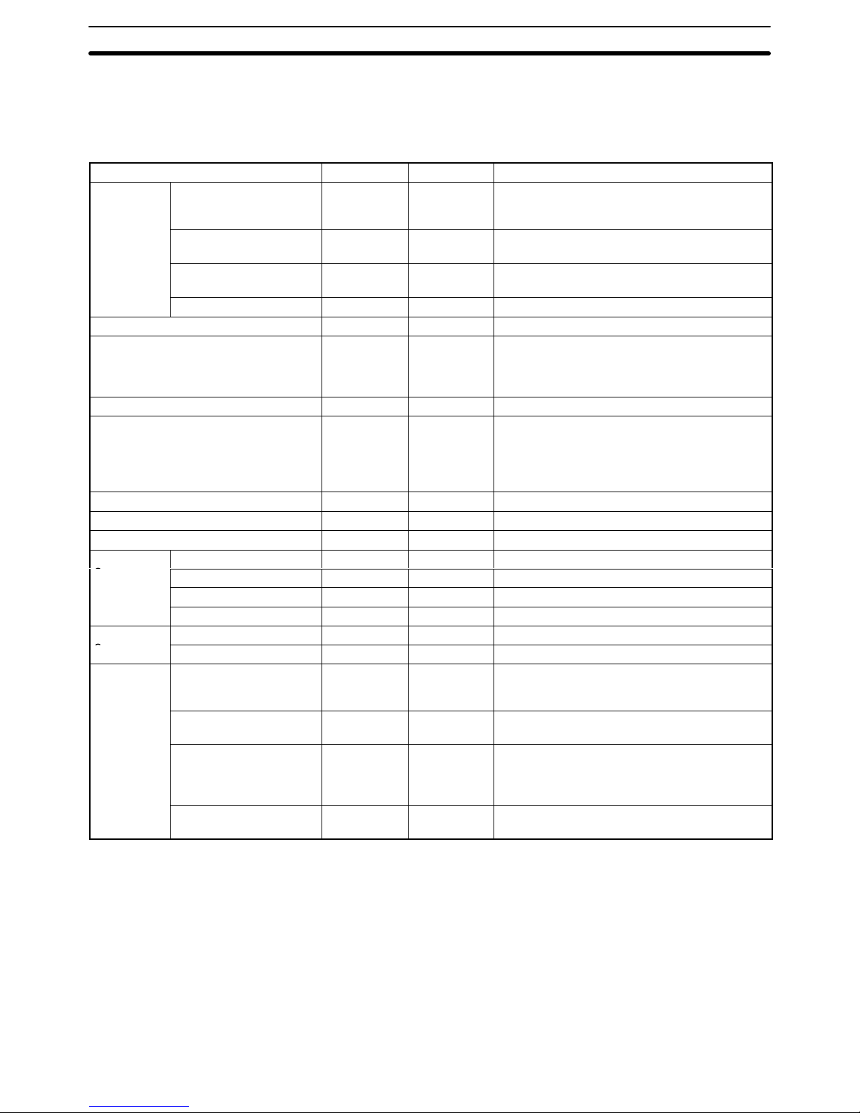
Tables
are also provided of new products included for the first
time in this version of the manual, along with
a comparison of CPU capabilities, and a list of improvements made in recent CPU versions.
Section
2
describes the overall configuration that the PC System
can take and introduces the main Units
used in the system configuration.
Section 3
provides procedures on installing and wiring.
Section 4
provides information on ongoing maintenance.
Section 5
describes general troubleshoot and provides troubleshooting flowcharts.
Appendix A
provides tables of C- and CV-series products that can be used with CV-series PCs.
Appendix
B
provides general PC specifications, dimensions, and I/O Unit specifications (including inter
-
nal circuit configurations and wiring diagrams).
WARNING Failure to read and understand the information provided in this manual may result in
personal injury or death, damage to the product, or product failure. Please read each
section
in its entirety and be sure you understand the information provided
in the section
and related sections before attempting any of the procedures or operations given.
!

xi
PRECAUTIONS
This section provides general precautions for using the Programmable Controller (PC) and related devices.
The
information contained in this section is important for the safe and r
eliable application of the Pr
ogrammable Con
-
troller. You must r
ead this section and understand the information contained befor
e attempting to set up or operate a
PC
system.
1 Intended Audience . . . . . . . . . . . . . . . . . . . . . . . . . . . . . . . . . . . . . . . . . . . . . . . . . . . . . . . . . . . .
2 General Precautions . . . . . . . . . . . . . . . . . . . . . . . . . . . . . . . . . . . . . . . . . . . . . . . . . . . . . . . . . . .
3 Safety Precautions . . . . . . . . . . . . . . . . . . . . . . . . . . . . . . . . . . . . . . . . . . . . . . . . . . . . . . . . . . . .
4 Operating Environment Precautions . . . . . . . . . . . . . . . . . . . . . . . . . . . . . . . . . . . . . . . . . . . . . .
5 Application Precautions . . . . . . . . . . . . . . . . . . . . . . . . . . . . . . . . . . . . . . . . . . . . . . . . . . . . . . . .
6 Conformance to EC Directives . . . . . . . . . . . . . . . . . . . . . . . . . . . . . . . . . . . . . . . . . . . . . . . . . .

!
!
!
!
!
!
3Safety Precautions
xii
1 Intended Audience
This
manual is intended for the following personnel, who must also have knowl
-
edge of electrical systems (an electrical engineer or the equivalent).
• Personnel in charge of installing FA systems.
• Personnel in charge of designing FA systems.
• Personnel in charge of managing FA systems and facilities.
2 General Precautions
The
user must operate the product according to the performance specifications
described in the operation manuals.
Before
using the product under conditions which are
not described in the manual
or applying the product to nuclear control systems, railroad systems, aviation
systems, vehicles, combustion systems, medical equipment, amusement machines, safety equipment, and other systems, machines, and equipment that
may
have a serious influence on lives and property if
used improperly
, consult
your OMRON representative.
Make sure that the ratings and performance characteristics of the product are
sufficient
for
the systems, machines, and equipment, and be sure to provide the
systems, machines, and equipment with double safety mechanisms.
This manual provides information for programming and operating the Unit. Be
sure
to read this manual before attempting to use the
Unit and keep this manual
close at hand for reference during operation.
WARNING It is extremely important that a PC and all PC Units be used for the specified
purpose
and under the specified conditions, especially in applications that can
directly or indirectly affect human life. You must consult with your OMRON
representative before applying a PC System to the above-mentioned
applications.
3 Safety Precautions
WARNING Do
not attempt to take any Unit apart while the power is being supplied. Doing
so
may result in electric shock.
WARNING Do not touch any of the terminals or terminal blocks while the power is being
supplied. Doing so may result in electric shock.
WARNING Do
not
attempt to disassemble, repair
. or modify any Units. Any attempt to do so
may result in malfunction, fire, or electric shock.
WARNING There is a lithium battery built into the SRAM Memory Cards. Do not short the
positive
and negative terminals of the battery
, charge the battery, attempt to take
it apart, subject it to pressures that would deform it, incinerate it, or otherwise
mistreat it. Doing any of these could cause the battery to erupt, ignite, or leak.
Caution Tighten the screws on the terminal block of the AC Power Supply Unit to the
torque
specified in the operation manual. The loose screws may result in
burning
or malfunction.

!
!
!
!
!
5Application Precautions
xiii
4 Operating Environment Precautions
Caution Do not operate the control system in the following places:
• Locations subject to direct sunlight.
• Locations subject to temperatures or humidity outside the range specified in
the specifications.
• Locations
subject to condensation as the result of severe changes in tempera
-
ture.
• Locations subject to corrosive or flammable gases.
• Locations subject to dust (especially iron dust) or salts.
• Locations subject to exposure to water, oil, or chemicals.
• Locations subject to shock or vibration.
Caution Take
appropriate and suf
ficient countermeasures when installing systems in the
following locations:
• Locations subject to static electricity or other forms of noise.
• Locations subject to strong electromagnetic fields.
• Locations subject to possible exposure to radioactivity.
• Locations close to power supplies.
Caution The
operating environment of the PC
System can have a large ef
fect on the lon
-
gevity
and reliability of the system. Improper operating environments can lead to
malfunction,
failure, and other
unforeseeable problems with the PC System. Be
sure
that the operating environment is within the specified conditions at installa
-
tion and remains within the specified conditions during the life of the system.
5 Application Precautions
Observe the following precautions when using the PC System.
WARNING Always heed these precautions. Failure to abide by the following precautions
could lead to serious or possibly fatal injury.
• Always
ground the system to 100 Ω or less when installing the Units. Not con
-
necting to a ground of 100 Ω or less may result in electric shock.
• Always
turn OFF the power supply to the PC before attempting any of the fol
-
lowing.
Not turning OFF the power supply may result in malfunction or
electric
shock.
• Mounting
or dismounting I/O Units, Memory Cassettes, or any other Units.
• Setting switches.
• Connecting cables or wiring the system.
• Connecting or disconnecting the connectors.
Caution Failure
to abide by the following precautions could lead to faulty operation of the
PC
or the system, or
could damage the PC or PC Units. Always heed these pre
-
cautions.
• Fail-safe measures must be taken by the customer to ensure safety in the
event
of incorrect, missing, or abnormal signals caused by broken signal lines,
momentary power interruptions, or other causes.

6Conformance to EC Directives
xiv
• Interlock
circuits, limit circuits,
and similar safety measures in external circuits
(i.e.,
not in the Programmable Controller) must be provided by the customer
.
• Always
use the power supply voltage specified in the operation manuals. An
incorrect voltage may result in malfunction or burning.
• Take
appropriate measures to ensure that the specified power with the rated
voltage
and frequency is supplied. Be particularly careful in places where the
power
supply is unstable. An incorrect power supply may result in malfunction.
• Install
external breakers and take other safety measures against short-circuit
-
ing
in external wiring. Insuf
ficient safety measures against short-circuiting may
result in burning.
• Do not apply voltages to the Input Units in excess of the rated input voltage.
Excess voltages may result in burning.
• Do not apply voltages or connect loads to the Output Units in excess of the
maximum
switching capacity
. Excess voltages or loads may result in
burning.
• Disconnect
the functional ground terminal when
performing withstand voltage
tests.
Not disconnecting the functional ground terminal may result in burning.
• Install
the Unit properly as
specified in the operation manual. Improper installa
-
tion of the Unit may result in malfunction.
• Be sure that all the mounting screws, terminal screws, and cable connector
screws
are tightened to the torque specified in the
relevant manuals. Incorrect
tightening torque may result in malfunction.
• Use
crimp terminals for wiring. Do not connect bare stranded wires directly to
terminals. Connection of bare stranded wires may result in burning.
• Double-check
all the wiring before turning on the power supply
. Incorrect wir
-
ing may result in burning.
• Be
sure that the terminal blocks, Memory
Units, expansion cables, and other
items with locking devices are properly locked into place. Improper locking
may result in malfunction.
• Check
the user program for proper execution before actually running it on the
Unit. Not checking the program may result in an unexpected operation.
• Confirm
that no adverse ef
fect will occur in the system before attempting any of
the following. Not doing so may result in an unexpected operation.
• Changing the operating mode of the PC.
• Force-setting/force-resetting any bit in memory.
• Changing the present value of any word or any set value in memory.
• Resume
operation only after transferring to the new CPU Unit the contents of
the DM Area, HR Area, and other data required for resuming operation. Not
doing so may result in an unexpected operation.
• Do
not pull on the cables or bend the cables beyond their natural limit.
Doing
either of these may break the cables.
• Do not place objects on top of the cables. Doing so may break the cables.
6 Conformance to EC Directives
The
CV
-series PCs that comply with EC Directives must be installed as follows:
1, 2, 3...
1. The
CV
-series PCs are designed for installation inside control panels. The
PC must be installed within a control panel.
2. Use
reinforced insulation or double
insulation for the DC power supplies to
be connected to the DC I/O Units for CV500-PS211. Use separate power
supplies
as the external power supplies for the Relay Output Units and the
power supplies for the DC I/O Units.
3. To
meet the EC Directives (Low V
oltage Directive), the maximum switching
capacity while the CV500-PS211 is being operated is 24 VDC/2 A.
6Conformance to EC Directives
xv
4. PCs
complying with EC Directives also conform to the Common Emission
Standard
(EN50081-2). When a PC is built
into a machine, however
, noise
can be generated by switching devices using relay outputs and cause the
overall machine to fail to meet the Standards. If this occurs, surge killers
must be connected or other measures taken external to the PC.
The following methods represent typical methods for reducing noise, and
may not be sufficient in all cases. Required countermeasures will vary
depending
on the devices connected to the
control panel, wiring, the config
-
uration of the system, and other conditions.
Countermeasures
Refer to EN50081-2 for more details.
Countermeasures are not required if the frequency of load switching for the
whole system including the PC is less than 5 times per minute.
Countermeasures
are required if the frequency of load switching for the whole
system including the PC is 5 or more times per minute.
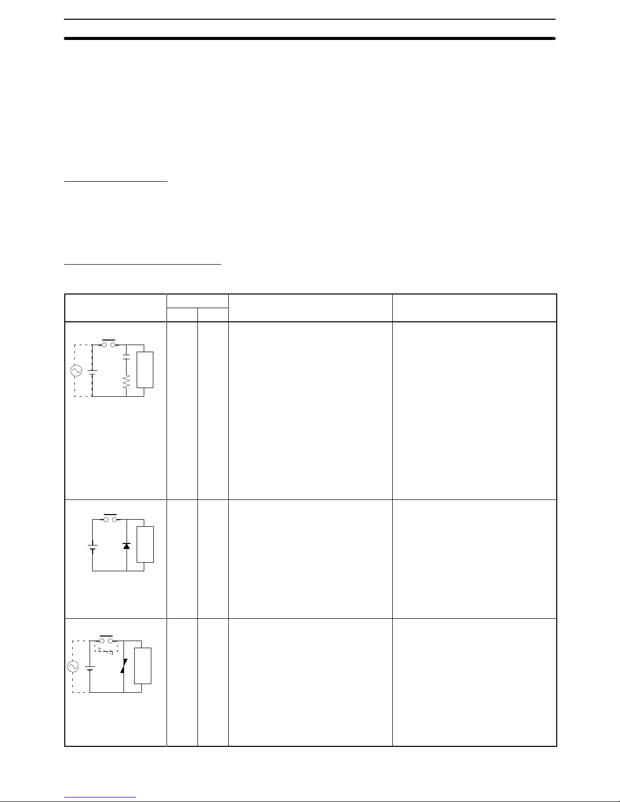
Countermeasure Examples
When
switching an inductive load, connect a surge protector
, diodes, etc., in par
-
allel with the load or contact as shown below.
Circuit Current Characteristic Required element
AC DC
CR method
Power
supply
Inductive
load
Yes Yes If the load is a relay or solenoid, there
is a time lag between the moment the
circuit is opened and the moment the
load is reset.
If the supply voltage is 24 or 48 V,
insert the surge protector in parallel
with the load. If the supply voltage is
100 to 200 V, insert the surge
protector between the contacts.
The capacitance of the capacitor must
be 1 to 0.5
µF per contact current of
1
A and resistance of the resistor must
be 0.5 to 1
Ω per contact voltage of
1 V. These values, however, vary with
the load and the characteristics of the
relay. Decide these values from
testing, and take into consideration
that the capacitance suppresses spark
discharge when the contacts are
separated and the resistance limits
the current that flows into the load
when the circuit is closed again.
The dielectric strength of the capacitor
must be 200 to 300 V. If the circuit is
an AC circuit, use a capacitor with no
polarity.
Diode method
Power
supply
Inductive
load
No Yes The diode connected in parallel with
the load changes energy accumulated
by the coil into a current, which then
flows into the coil so that the current
will be converted into Joule heat by
the resistance of the inductive load.
This time lag, between the moment
the circuit is opened and the moment
the load is reset, caused by this
method is longer than that caused by
the CR method.
The reversed dielectric strength value
of the diode must be at least 10 times
as large as the circuit voltage value.
The forward current of the diode must
be the same as or larger than the load
current.
The reversed dielectric strength value
of the diode may be two to three times
larger than the supply voltage if the
surge protector is applied to electronic
circuits with low circuit voltages.
Varistor method
Power
supply
Inductive
load
Yes Yes The varistor method prevents the
imposition of high voltage between the
contacts by using the constant voltage
characteristic of the varistor. There is
time lag between the moment the
circuit is opened and the moment the
load is reset.
If the supply voltage is 24 or 48 V,
insert the varistor in parallel with the
load. If the supply voltage is 100 to
200 V, insert the varistor between the
contacts.
---

6Conformance to EC Directives
xvi
When
switching a load with a high
inrush current such as an incandescent lamp,
suppress the inrush current as shown below.
OUT
COM
R
OUT
COM
R
Countermeasure
1
Providing a dark current of approx.
one-third of the rated value through
an incandescent lamp
Countermeasure 2
Providing a limiting resistor

1
SECTION 1
Introduction
This
section provides general information about
Programmable Controllers and how they fit into a Control System. It also list
the
C-series products that can be used with the CV
-series PCs and operation manuals available for CV
-series products. Finally
,
this
section introduces Systems that can be used to create networks and enable remote I/O.
1-1
Control Systems
. . . . . . . . . . . . . . . . . . . . . . . . . . . . . . . . . . . . . . . . . . . . . . . . . . . . . . . . . .
1-2 The Role of the PC . . . . . . . . . . . . . . . . . . . . . . . . . . . . . . . . . . . . . . . . . . . . . . . . . . . . . . . .
1-2-1
Input Devices
. . . . . . . . . . . . . . . . . . . . . . . . . . . . . . . . . . . . . . . . . . . . . . . . . . . . .
1-2-2
Output Devices
. . . . . . . . . . . . . . . . . . . . . . . . . . . . . . . . . . . . . . . . . . . . . . . . . . .
1-3 PC Operation . . . . . . . . . . . . . . . . . . . . . . . . . . . . . . . . . . . . . . . . . . . . . . . . . . . . . . . . . . . .
1-4 CV
-series Manuals
. . . . . . . . . . . . . . . . . . . . . . . . . . . . . . . . . . . . . . . . . . . . . . . . . . . . . . . .
1-5 C-series–CV-series System Compatibility . . . . . . . . . . . . . . . . . . . . . . . . . . . . . . . . . . . . . .
1-6
Networks and Remote I/O Systems
. . . . . . . . . . . . . . . . . . . . . . . . . . . . . . . . . . . . . . . . . . .
1-7
New CPUs and Related Units
. . . . . . . . . . . . . . . . . . . . . . . . . . . . . . . . . . . . . . . . . . . . . . .
1-8
CPU Comparison
. . . . . . . . . . . . . . . . . . . . . . . . . . . . . . . . . . . . . . . . . . . . . . . . . . . . . . . . .
1-9 Improved Specifications . . . . . . . . . . . . . . . . . . . . . . . . . . . . . . . . . . . . . . . . . . . . . . . . . . . .
1-9-1 Upgraded Specifications . . . . . . . . . . . . . . . . . . . . . . . . . . . . . . . . . . . . . . . . . . . .
1-9-2 V
ersion-1 CPUs
. . . . . . . . . . . . . . . . . . . . . . . . . . . . . . . . . . . . . . . . . . . . . . . . . . .
1-9-3 V
ersion-2 CVM1 PCs
. . . . . . . . . . . . . . . . . . . . . . . . . . . . . . . . . . . . . . . . . . . . . .

2
1-1 Control Systems
A
Control
System is the electronic equipment needed to control a particular pro
-
cess.
It may include everything from a process control computer
, to the factory
computer,
down through the PCs, and then on down through the network to the
I/O
devices: control components like the switches, stepping motors,
solenoids,
and sensors which monitor and control mechanical operations.
PC PC PC
PCs
Process Control Computer
Factory Computer
I/O devices
A
Control System can involve very large applications where many dif
ferent mod
-
els
of PC are networked together or it could be an application as small as a single
PC controlling a number of output devices.
1-2 The Role of the PC
The
PC is the part of the Control System that directly controls the manufacturing
process. According to the program stored in its memory, the PC accepts data
from the input devices connected to it and uses this data to monitor the controlled system. When the program calls for some action to take place, the PC
sends data to the output devices connected to it to cause that action to take
place.
The PC may be used to control
a simple, repetitive task, or it may be con
-
nected
to other PCs or to a host computer in order to integrate the control of a
complex process.
The Role of the PC Section 1-2
3
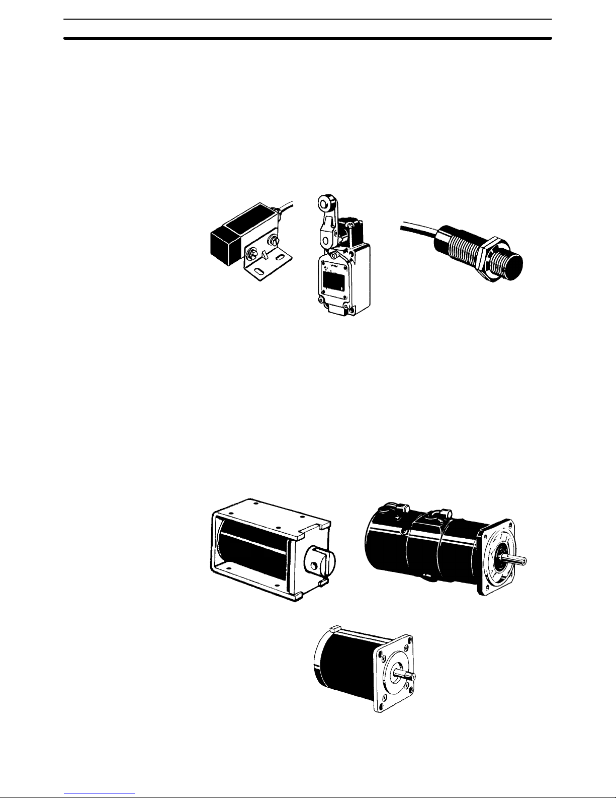
1-2-1 Input Devices
PCs
can receive inputs from either automated or
manual devices. The PC could
receive
data from the user via a pushbutton
switch, keyboard, or similar device.
Automated
inputs could come
from a variety of devices: micro-switches, timers,
encoders,
photoelectric sensors, and so on. Some devices, like the limit switch
shown
below
, turn ON or OFF
when the equipment actually makes contact with
them.
Other devices, like the photoelectric sensor and proximity sensor shown
below,
use other means, such as light or inductance, in order to get information
about the equipment being monitored.
Photoelectric
Sensor
Limit Switch
Proximity Sensor
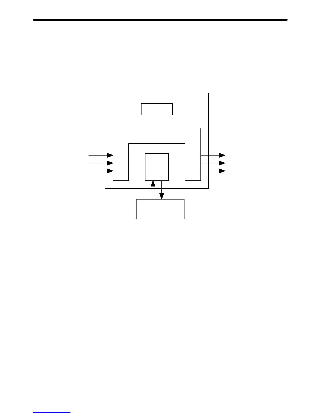
1-2-2 Output Devices
A
PC can output to a myriad of devices for use in automated control. Almost
any
-
thing
that you can think of could be controlled by a PC. Some of the most com
mon devices are motors, solenoids, servomotors, stepping motors, valves,
switches,
indicator lights, buzzers, and alarms. Some of these output devices,
such
as the motors, solenoids, servomotors, stepping motors, and valves,
af
fect
the
controlled system directly
. Others, such as the indicator lights, buzzers, and
alarms,
provide outputs to notify personnel operating or monitoring the system.
Solenoid
Servomotor
Stepping Motor
The Role of the PC Section 1-2
4
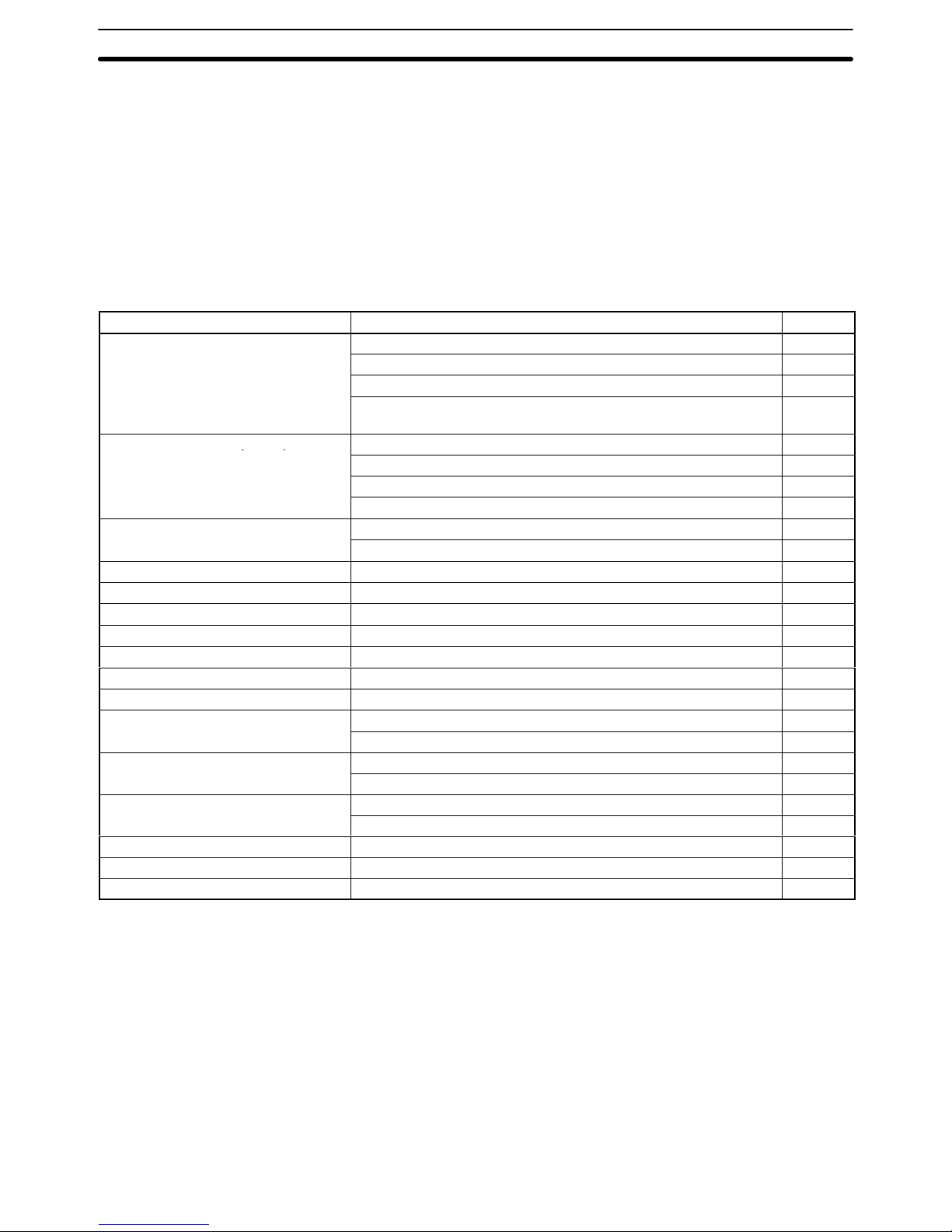
1-3 PC Operation
PCs operate by monitoring input signals and providing output signals. When
changes are detected in input signals, the PC reacts through the user-programmed
internal
logic to produce output signals. The PC continually executes
the program in its memory to achieve this control.
Block Diagram of PC
Power Supply
Input Output
CPU
Memory
Programming
Device
Signals
from
switches,
sensors,
etc.
Signals to
Solenoids,
motors,
etc.
A program for your applications must be designed and stored in the PC. This
program is then executed as part of the cycle of internal operations of the PC.
Execution Cycle When a PC operates, i.e., when it executes its program to control an external
system, a series of operations are performed inside the PC. These internal oper
ations can be broadly classified into the following four categories. Refer to the
CV-series PCs Operation Manual: Ladder Diagrams
for details.
1, 2, 3...
1. Common
(or overseeing) processes, such as watchdog timer operation and
testing the program memory.
2. Data input and output.
3. Program execution.
4. Peripheral device servicing.
Cycle Time The
total time required for a PC to perform all these internal operations is called
the cycle time.
Timing
is one of the most important factors in designing a Control System.
For
accurate
operations, it is necessary to have answers to such
questions as these:
• How
long does it take for the PC to execute all the instructions in its memory?
• How
long does it take for the PC to produce a control
output in response to a
given input signal?
PC Operation Section 1-3
5
The
cycle time of the PC can be automatically calculated and monitored,
but it is
necessary to have an understanding of the timing relationships within the PC
for
effective
System
design and programming. Refer to the
CV
-series PCs Opera
tion
Manual: Ladder Diagrams
for details on internal PC processing and to
the
CVSS Operation Manuals
for details on monitoring the cycle time.
1-4 CV-series Manuals
The
following manuals are available for the various CV
-series products. Other
manuals
are
also available for compatible C-series products (see next section).
Catalog
number suf
fixes have been omitted; be sure you have
the most recent
version for your region.
Product Manual Cat. No.
CV-series PCs CV-series PCs Installation Guide W195
CV-series PCs Operation Manual: SFC W194
CV-series PCs Operation Manual: Ladder Diagrams W202
CV-series PCs Operation Manual: Host Link System,
CV500-LK201 Host Link Unit
W205
CV Support Software (CVSS)
The CV Series Getting Started Guidebook W203
()
CV Support Software Operation Manual: Basics W196
CV Support Software Operation Manual: Offline W201
CV Support Software Operation Manual: Online W200
SYSMAC Support Software (SSS) SYSMAC Support Software Operation Manual: Basics W247
SYSMAC Support Software Operation Manual: CVM1 PCs W249
Graphic Programming Console (GPC) CV500-MP311-E Graphic Programming Console Operation Manual W216
Programming Console CVM1-PRS21-E Programming Console Operation Manual W222
SYSMAC NET Link System SYSMAC NET Link System Manual W213
SYSMAC LINK System SYSMAC LINK System Manual W212
SYSMAC BUS/2 Remote I/O System SYSMAC BUS/2 Remote I/O System Manual W204
CompoBus/D (DeviceNet) CompoBus/D (DeviceNet) Operation Manual W267
CV-series Ethernet Unit CV-series Ethernet System Manual W242
BASIC Unit BASIC Unit Reference Manual W207
BASIC Unit Operation Manual W206
Personal Computer Unit
Personal Computer Unit Operation Manual W251
Personal Computer Unit Technical Manual W252
Motion Control Unit
Motion Control Unit Operation Manual: Introduction W254
Motion Control Unit Operation Manual: Details W255
Temperature Controller Data Link Unit CV500-TDL21 Temperature Controller Data Link Unit W244
Memory Card Writer CV500-MCW01-E Memory Card Writer Operation Manual W214
Optical Fiber Cable Optical Fiber Cable Installation Guide W156
CV-series Manuals Section 1-4
6
1-5 C-series–CV-series System Compatibility
The
following table shows when C-series Units can be used and when CV
-series
Units must be used. Any C-series Unit or Peripheral Device not listed in this table
cannot be used with the CV-series PCs.
Unit C Series CV Series Remarks
CPU Rack CPU No Yes CV500-CPU01-EV1, CV1000-CPU01-EV1,
CV2000-CPU01-EV1, CVM1-CPU01-EV2,
CVM1-CPU11-EV2, and CVM1-CPU21-EV2
Power Supply No Yes CV500-PS221, CV500-PS21
1, and
CVM1-PA208
CPU Backplane No Yes CV500-BC031, CV500-BC051, CV500-BC101,
CVM1-BC103, and CVM1-BC053
I/O Control Unit No Yes CV500-ICj01
Expansion CPU Backplane No Yes CV500-BI111
Expansion I/O Backplane No Yes CV500-BI042, CV500-BI062, CV500-BI112,
CVM1-BI114, and CVM1-BI064 (C500
Expansion I/O Racks can be used with certain
limitations.)
16-/32-/64-point I/O Units Yes Yes --Special I/O Units Yes Yes Applicable Units include Analog Input, Analog
Output, High-speed Counter, PID, Position
Control, Magnetic Card, ASCII, ID Sensor
, and
Ladder Program I/O Units (The C500-ASC03
cannot be used.)
BASIC Unit No Yes CV500-BSCj1
Personal Computer Unit No Yes CV500-VP213-E/217-E/223-E/227-E
Temperature Control Data Link Unit No Yes CV500-TDL21
Link
SYSMAC NET No Yes CV500-SNT31
Systems
SYSMAC LINK No Yes CV500-SLK11 and CV500-SLK21
Host Link Unit No Yes CV500-LK201
Ethernet Unit No Yes CV500-ETN01
Remote I/O
SYSMAC BUS Units Yes Yes ---
Systems
SYSMAC BUS/2 No Yes CV500-RM211/221 and CV500-RT211/221
Peripheral
Devices
CV Support Software No Yes
(See note.)
CV500-ZS3AT1-EV2 (3 1/2” floppy disks) and
CV500-ZS5AT1-EV2 (5 1/4” floppy disks) for
IBM PC/AT compatible
SYSMAC Support
Software (SSS)
Yes Yes
(See note.)
C500-ZL3AT1-E (3.5” floppy disks) for IBM
PC/AT compatible
Graphic Programming
Console
Yes (Main
unit only)
Yes
(System
Cassette)
(See note.)
GPC: 3G2C5-GPC03-E
System Cassette: CV500-MP311-E
Programming Console No Yes
(See note.)
CVM1-PRS21-EV1 (set)
Note The
CVSS does
not support new instructions added for version-2 CVM1 PCs.
The
SSS does not
support SFC programming (CV500, CV1000, and CV2000).
New instructions added for version-2 CVM1 PCs are also supported by version-1
CV
-series Programming Consoles.
C-series–CV-series System Compatibility Section 1-5
7
1-6 Networks and Remote I/O Systems
Systems
that can be used to create networks and enable remote I/O are intro
-
duced
in this section. Refer
to the operation manuals for the Systems for details.
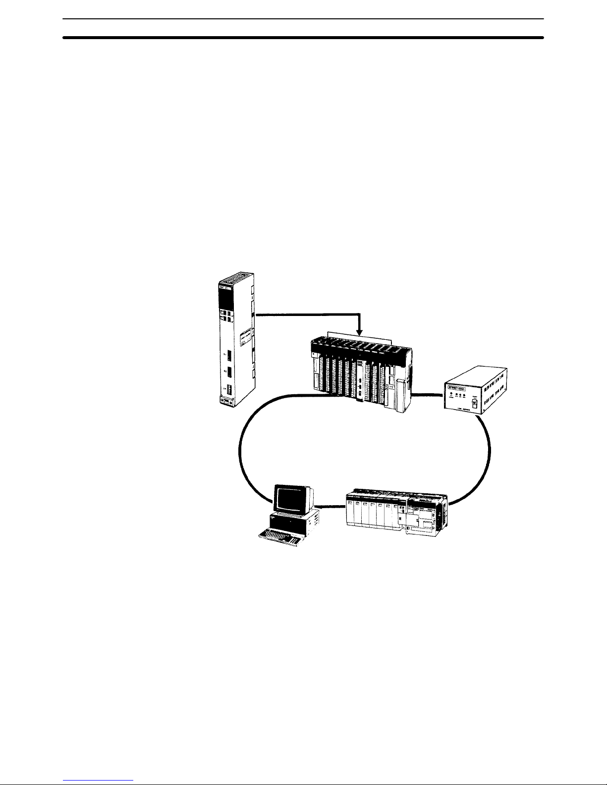
The
SYSMAC NET Link System is
a LAN (local area network) for use in factory
automation
systems. The SYSMAC NET Link System can consist of up to 128
nodes among which communications may be accomplished via datagrams,
data transfers, or automatic data links.
Datagrams
transmit and receive data using a
command/response format. Com
mands can be issued from the user program by the DELIVER COMMAND instruction (CMND(194)).
Data can also be transmitted and received using the NETWORK SEND and
NETWORK RECEIVE (SEND(192)/RECV(193)) instructions in the user program. Up to 256 words of data can be transferred for each instruction.
Automatic data links allow PCs and computers to create common data areas.
SYSMAC
NET Link Unit
CV500-SNT31
Up to 4 Units can
be mounted.
CV-series
CPU Rack/Expansion CPU Rack
Line Server
Center Power
Feeder
C200H
C500
C1000H
C2000H
Personal
computer
Note Up to four SYSMAC NET Link Units (CV500-SNT31) can be mounted to the
CPU Rack and/or Expansion CPU Rack of each CV-series PC.
SYSMAC NET Link System
Networks and Remote I/O Systems Section 1-6

8
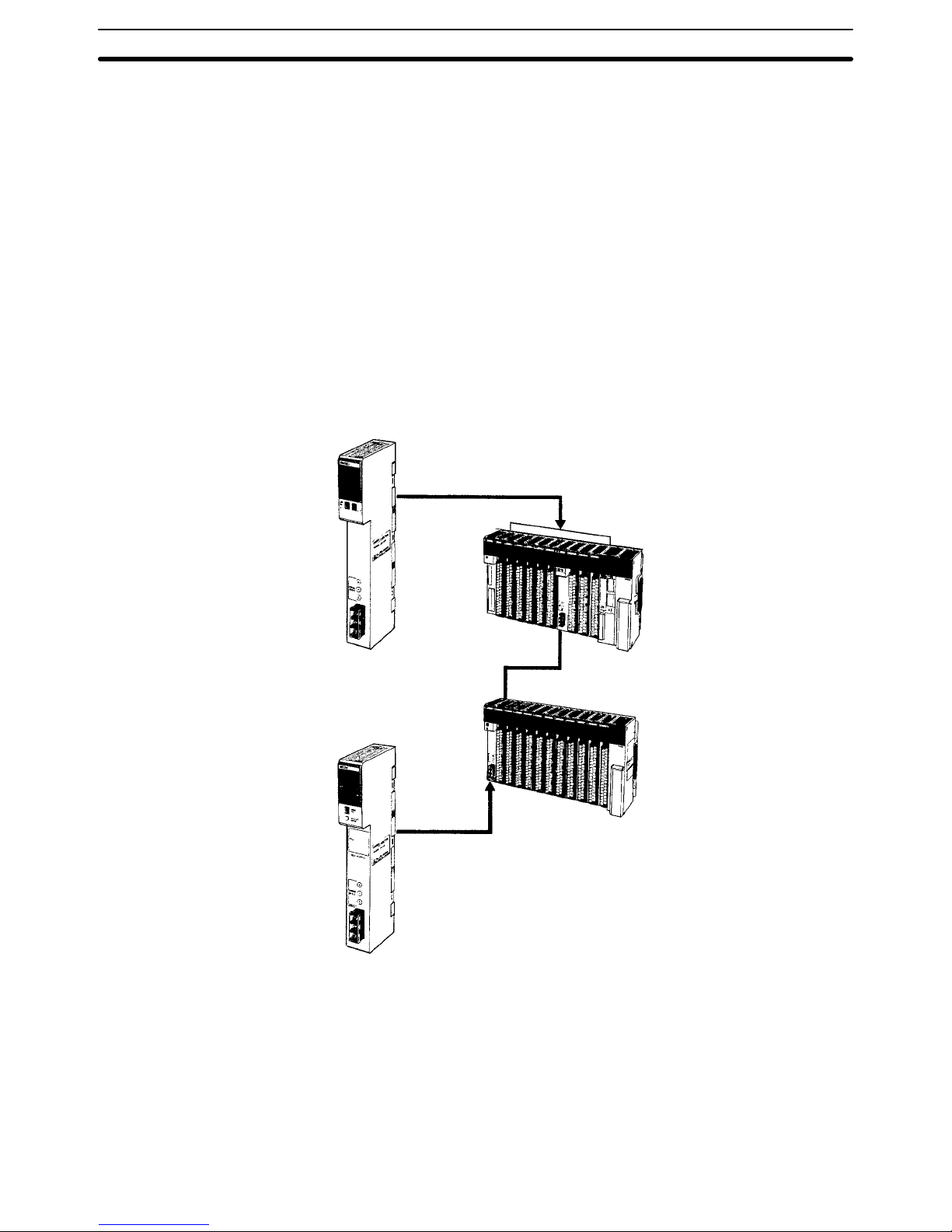
SYSMAC LINK System Networks
can also be created using SYSMAC LINK Systems.
A SYSMAC LINK
System can consist of up to 62 PCs, including the CV500, CV1000, CV2000,
CVM1,
C200H, C1000H, and C2000H. Communications between the PCs is ac
-
complished
via datagrams, data transfers, or automatic data links in ways simi
-
lar to the SYSMAC NET Link System.
The
main dif
ferences between
SYSMAC NET Link and SYSMAC LINK Systems
is
in the structure of automatic data links and in the system configuration, e.g.,
only
PCs
can be linked in SYSMAC LINK Systems, whereas other devices can
form nodes in SYSMAC NET Link Systems.
Datagrams
transmit and receive data using a
command/response format. Com
mands can be issued from the user program by the DELIVER COMMAND instruction (CMND(194)).
Data can also be transmitted and received using the NETWORK SEND and
NETWORK RECEIVE (SEND(192)/RECV(193)) instructions in the user program. Up to 256 words of data can be transferred for each instruction.
Automatic data links allow PCs and computers to create common data areas.
SYSMAC
LINK Unit
CV500-SLK1
1 (optical)
CV500-SLK21 (wired)
Up to 4 Units can
be mounted.
CV-series
CPU Rack/Expansion CPU Rack
CV500/CV1000/
CV2000/CVM1
C200H/C1000H/
C2000H
Note Up to four SYSMAC LINK Units (CV500-SLK11/21) can be mounted the CPU
Rack and/or Expansion CPU Rack of each CV-series PC.
Networks and Remote I/O Systems Section 1-6
9
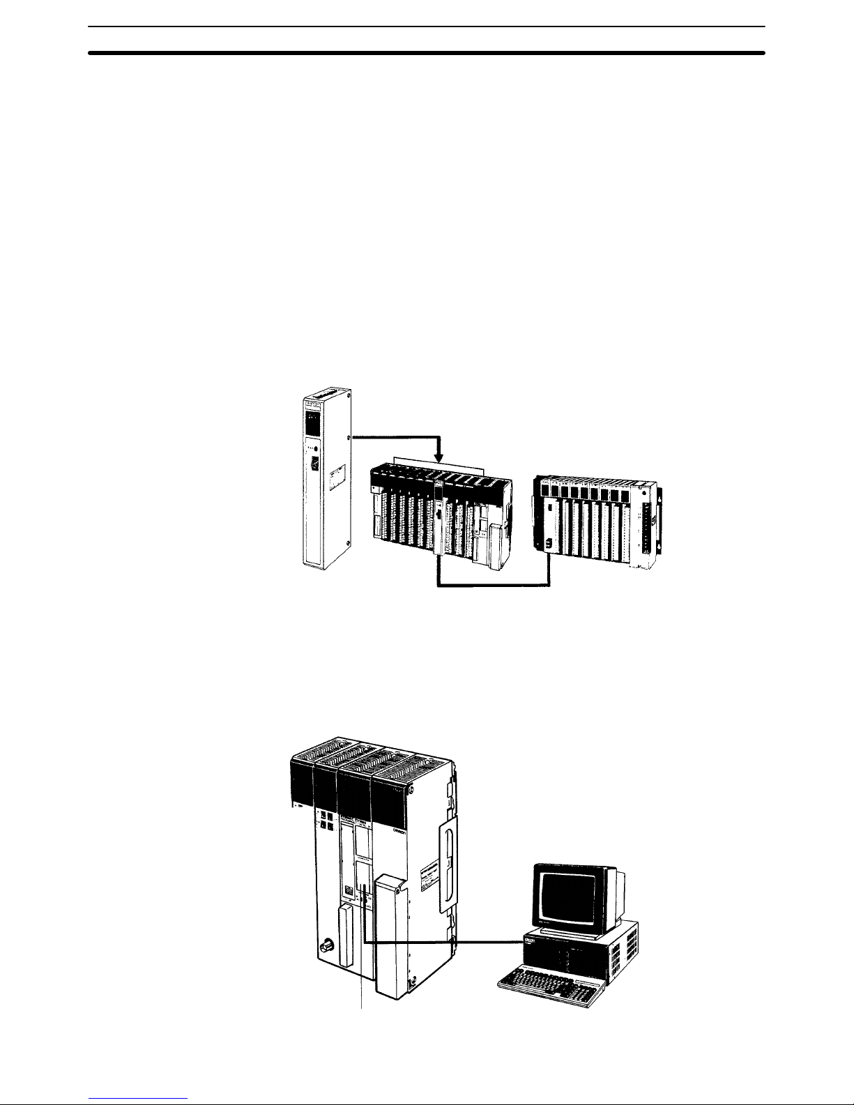
Remote
I/O can be enabled by adding a SYSMAC BUS/2 Remote I/O System
to
the
PC. The SYSMAC BUS/2 Remote I/O System is available in two types: opti
cal and wired.
Two
Remote
I/O Master Units, optical or wired, can be mounted to the CV500 or
CVM1-CPU01-EV2 CPU Rack or Expansion CPU Rack. Four Remote
I/O
Mas
ter Units can be mounted to the CV1000, CV2000, or CVM1-CPU11/21-EV2
CPU Rack or Expansion CPU Rack.
Up to eight Remote I/O Slave Racks can be connected per PC.
Slaves can be used to provide up to 1,024 remote I/O points for the CV500 or
CVM1-CPU01-EV2;
up to 2,048 remote I/O points for the CV1000, CV2000, or
CVM1-CPU11/21-EV2.
These limits are the totals for all Slaves control by one
PC.
A
Programming Device (such as the
CVSS) can be connected to up to two Re
mote I/O Slave Units for each Remote I/O Master Unit as long as a total of no
more than four Programming Devices are connected per PC.
Remote
I/O Master Unit
CV500-RM21
1 (optical)
CV500-RM221 (wired)
CV500, CVM1-CPU01-EV2:
4 Masters max. can be mounted
CV1000, CV2000, CVM1-CPU1
1/21-EV2:
8 Masters max. can be mounted
CV-series
CPU Rack/Expansion CPU Rack
Remote I/O Slave
Up to 8 Slave can be con
nected per PC for 58M
Slaves; 4 Slaves for 122M
or 54MH Slaves.
Remote I/O Slave Unit
CV500-RT21
1 (optical)
CV500-R
T221 (wired)
SYSMAC BUS/2 Remote I/O
System
Networks and Remote I/O Systems Section 1-6
10
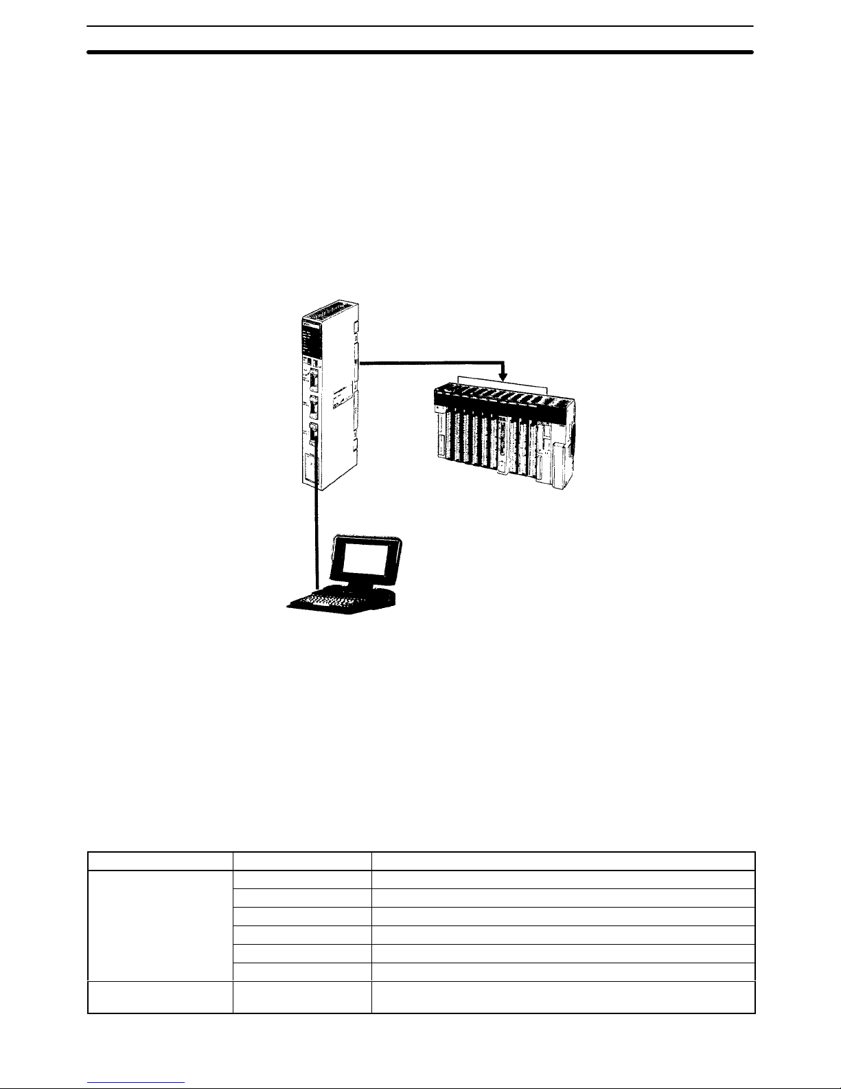
Remote
I/O can also be enabled by using the C-series
SYSMAC BUS Remote
I/O System with CV-series PC.
Remote
I/O
Master Units can be mounted on any slot of the CPU Rack, Expan
sion CPU Rack, or Expansion I/O Rack. Up to four Masters can be mounted for
the
CV500 or CVM1-CPU01-EV2, up to eight Masters for the CV1000, CV2000,
or CVM1-CPU11/21-EV2.
For each Master, up to two Slave Racks can be connected for the CV500 or
CVM1-CPU01-EV2; up to eight Slave Racks for the CV1000, CV2000, or
CVM1-CPU11/21-EV2.
No more than 16 Slave Racks can be connected per PC.
Slaves can be used to provide up to 512 remote I/O points for the CV500 or
CVM1-CPU01-EV2;
up to 1,024 remote I/O points for the CV1000, CV2000, or
CVM1-CPU11-EV2; up to 2,048 remote I/O points for the CVM1-CPU21-EV2.
These limits are the totals for all Slaves control by one PC.
Programming Devices cannot be connected to SYSMAC BUS Slave Racks.
Remote
I/O Master Unit
3G2A5-RM001-(P)EV1 (optical)
C500-RM201 (wired)
Up to 8 Units
CV-series
CPU Rack/Expansion CPU
Rack/Expansion I/O Rack
C-series
Remote I/O Slave Rack
CV500, CVM1-CPU01-EV2:
2 Masters max. can be mounted
CV1000, CV2000, CVM1-CPU1
1/21-EV2:
4 Masters max. can be mounted
The
CV
-series PCs can be connected to a host computer with the host link con
-
nector via the CPU or a CV500-LK201 Host Link Unit mounted to a Rack.
RS-232C
or RS-422 communications can be used depending on the switch set
-
ting.
When RS-422
is selected, up to 32 PCs can be connected to a single host.
Data is transmitted and received by commands and responses.
Host
link connector
Host
computer
SYSMAC BUS Remote I/O
System
Host Link System
(SYSMAC W
AY)
Networks and Remote I/O Systems Section 1-6
11
BASIC Unit The
BASIC Unit can be connected to a personal computer to enable communi
cations with the PC using the BASIC programming language. Up to 512 bytes
(256
words) of data
can be transferred between the BASIC Unit and the CPU by
the PC READ/WRITE command without using the PC program.
Up
to 256 words of data can also be transferred between the BASIC Unit and
the
PC’s CPU by using the NETWORK SEND and NETWORK RECEIVE
(SEND(192)/RECV(193)) instructions in the PC program.
Data
can also be transferred to other BASIC Units mounted on the same PC, or
to BASIC Units mounted to other PCs connected by networks formed using a
SYSMAC
NET Link
or SYSMAC LINK System. RS-232C, RS-422, Centronics,
and GPIB interfaces are available.
BASIC
Unit
CV500-BSCj1
Personal computer
CV-series
CPU Rack/Expansion
CPU Rack
Personal Computer Unit The
Personal Computer Unit is a full-fledged IBM PC/A
T compatible that can
be
used
to run independent programming directly on a
Rack to eliminate the need
for
separate installation space. It can run along or connected to any of the normal
peripherals
supported by IBM PC/A
T compatibles (mice, keyboards, monitors,
data
storage devices, etc.), and as a CPU Bus
Unit, the Personal Computer Unit
interfaces directly to the PC’
s CPU though the CPU bus to eliminate the need for
special interface hardware, protocols, or programming.
1-7 New CPUs and Related Units
The
following
new CV
-series CPUs and related Units are included in this version
of
the manual for the first time. Refer to relevant sections of this manual or the
CV-series PC Operation Manual: Ladder Diagrams
for further details.
Unit Model number Main specifications
CPU
CVM1-CPU01-EV2 I/O capacity: 512 pts; Ladder diagrams only
CVM1-CPU11-EV2 I/O capacity: 1,024 pts; Ladder diagrams only
CVM1-CPU21-EV2 I/O capacity: 2,048 pts; Ladder diagrams only
CV500-CPU01-EV1 I/O capacity: 512 pts; Ladder diagrams or SFC + ladder diagrams
CV1000-CPU01-EV1 I/O capacity: 1,024 pts; Ladder diagrams or SFC + ladder diagrams
CV2000-CPU01-EV1 I/O capacity: 2,048 pts; Ladder diagrams or SFC + ladder diagrams
Temperature Controller
Data Link Unit
CV500-TDL21 Connects up to 64 temperature control devices via 2 ports.
New CPUs and Related Units Section 1-7
12
1-8 CPU Comparison
The following table shows differences between the various CV-series CPUs.
CPU
CVM1-
CPU01-EV2
CVM1-
CPU11-EV2
CVM1-
CPU21-EV2
CV500-
CPU01-EV1
CV1000-
CPU01-EV1
CV2000-
CPU01-EV1
Ladder diagrams
Supported Supported Supported Supported Supported Supported
Program-
SFC
Not supported Not supported Not supported
Supported Supported Supported
ming
Instructions 284 284 285 169 170 170
Speed
Basic
instructions (ms)
0.15 to 0.45 0.125 to 0.375 0.125 to 0.375 0.15 to 0.45 0.125 to 0.375 0.125 to 0.375
Other
instructions (ms)
0.6 to 9.9 0.5 to 8.25 0.5 to 8.25 0.6 to 9.9 0.5 to 8.25 0.5 to 8.25
Program capacity (see note)
30K words 30K words 62K words 30K words 62K words 62K words
Local I/O capacity
512 pts
1,024 pts 2,048 pts
512 pts
1,024 pts 2,048 pts
Remote
SYSMAC BUS/2
1,024 pts 2,048 pts 2,048 pts 1,024 pts 2,048 pts 2,048 pts
I/O
capacity
SYSMAC BUS
512 pts
1,024 pts 2,048 pts
512 pts
1,024 pts 1,024 pts
DM Area 8K words 24K words 24K words 8K words 24K words 24K words
Expansion DM Area
Not supported Not supported
32K words
each for 8
banks
Not supported
32K words
each for 8
banks
32K words
each for 8
banks
Timers 512 1,024 1,024 512 1,024 1,024
Counters 512 1,024 1,024 512 1,024 1,024
SFC steps
None None None 512 1,024 1,024
Step Flags
None None None 512 1,024 1,024
T
ransition Flags
None None None 512 1,024 1,024
Note The useable program capacity is 28K words or 60K words.
1-9 Improved Specifications
1-9-1 Upgraded Specifications
The following improvements are applicable to all CV500-CPU01-E and
CV1000-CPU01-E CPUs with lot numbers in which the rightmost digit is 3
(jjj3) or higher.
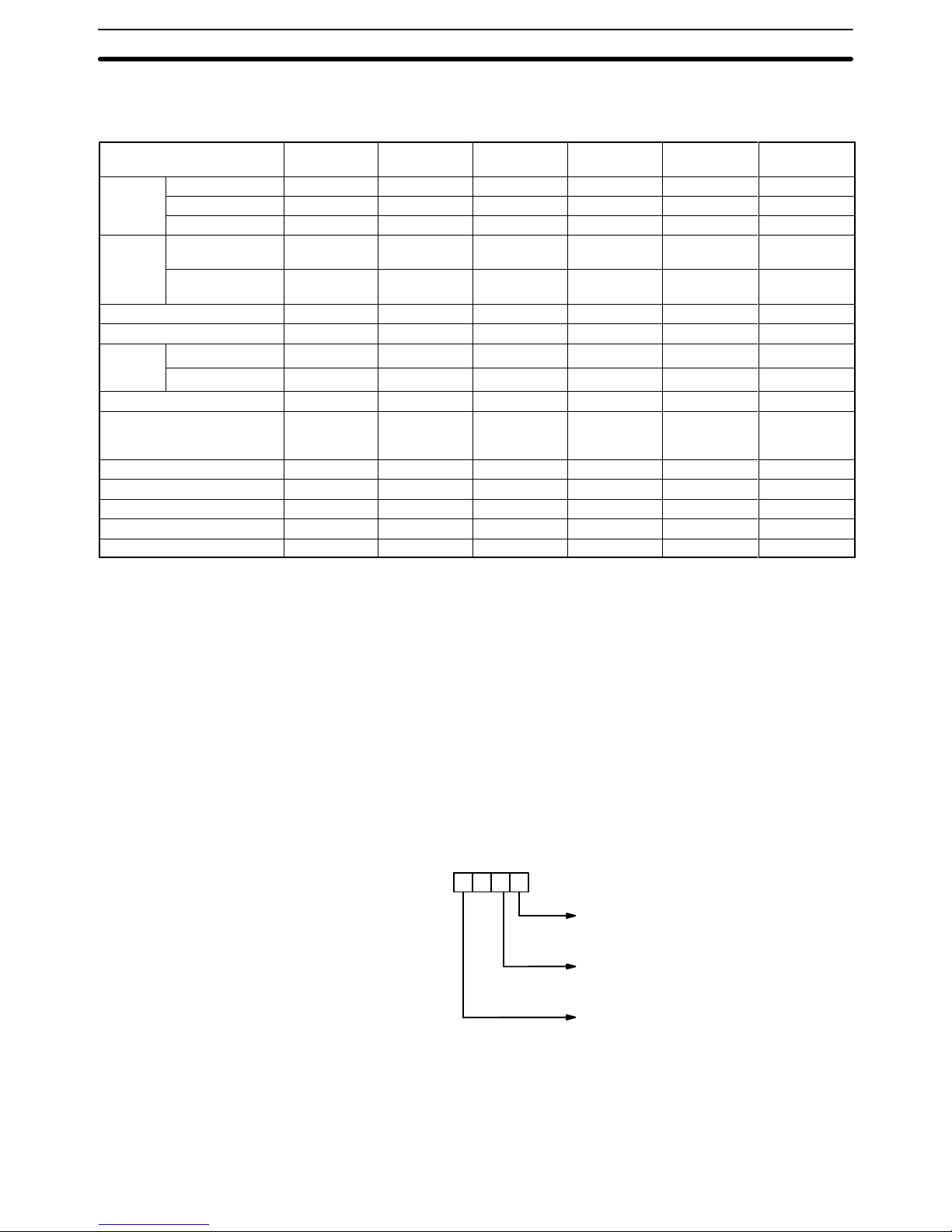
1, 2, 3...
1. The MLPX(110) (4-TO-16 DECODER) instruction has been improved to
also
function as a 8-to-256 decoder and the DMPX(111) (16-T
O-4 ENCOD
-
ER)
instruction has been improved to also function as a 256-to-8 encoder
.
To
enable this improvement, the digit designator
(Di) has been changed as
shown below.
Specifies
the first digit to be converted
4-to-16/16-to-4: 0 to 3
8-to-256/256-to-8: 0 or 1
Number of digits to be converted
4-to-16/16-to-4: 0 to 3 (1 to 4 digits)
8-to-256/256-to-8: 0 or 1 (1 or 2 digits)
Process
0: 4-to-16/16-to-4
1: 8-to-256/256-to-8
Digit number:
3210
0
2. The following operating parameter has been added to the PC Setup.
JMP(004) 0000 Processing
Y: Enable multiple usage (default)
N: Disable multiple usage
Improved Specifications Section 1-9

13
3. The
operation of Completion Flags for timers has been changed so that the
Completion Flag for a timer turns ON only when the timer instruction is
executed
with a PV of 0000
and not when the timer’s PV is refreshed to a PV
value of 0000, as was previously done.
Only
the timing of the activation of the Completion Flag
has been changed,
and
the
timer’s PV is still refreshed at the same times (i.e., when the timer
instruction is executed, at the end of user program execution, and every
80 ms if the cycle time exceeds 80 ms).
4. The
READ(190) (I/O READ) and WRIT(191) (I/O WRITE) instructions have
been improved so that they can be used for Special I/O Units on Slave
Racks under the following conditions.
a) The
lot number of the Remote I/O Master Unit and Remote I/O Slave Unit
must be the same as or latter than the following.
1992
October (Y
: November; Z: December)
1st
01 X 2
b) The DIP switch on the Remote I/O Slave Unit must be set to “54MH.”
c) The Special I/O Unit must be one of the following: AD101, CT012,
CT021,
CT041, ASC04, IDS01-V1, IDS02, IDS21, IDS22, or LDP01-V1.
(The
NC221-E, NC222, CP131, and FZ001 cannot be mounted to Slave
Racks.)
1-9-2 Version-1 CPUs
CV-series CPUs were changed to version 1 from December 1993. The new
model numbers are as follows: CVM1-CPU01-EV1, CVM1-CPU11-EV1,
CV500-CPU-EV1, CV1000-CPU-EV1, and CV2000-CPU-EV1. (Of these, all
CVM1
CPUs were changed to version 2 from December 1994; refer to the next
sections for details.)
The following additions and improvements were made to create the version-1
CPUs.
PT Link Function The
host
link interface on the CPU can be used to connect directly to Program
-
mable Terminals (PT
s) to create high-speed data links. T
o use the PT links,
turn
ON
pin 3 of the DIP switch on the CPU. Pin 3 must be turned OFF for host link
connections.
EEPROM Writes With
the new CPUs, you can write to EEPROM Memory Cards mounted to the
CPU
by using the file write operation from a
Peripheral Device. A Memory Card
Writer
is no longer required for this write operation. W
riting is possible in PRO
-
GRAM mode only.
New Command A
new I/O REGISTER command (QQ) has been added so that words from dif
fer-
ent data areas can be read at the same time.
Faster Host Links The
communications response time for the built-in host link interface
on the CPU
has been improved by a factor of approximately 1.2.
Faster Searches The search speed from Peripheral Devices for instructions and operands has
been nearly doubled.
1-9-3 Version-2 CVM1 PCs
CVM1 CPUs were changed to version 2 and a new CPU was added from December 1994. The new model numbers are as follows: CVM1-CPU01-EV2,
CVM1-CPU11-EV2, and CVM1-CPU21-EV2.
Improved Specifications Section 1-9

14
The following additions and improvements were made to create the version-2
CPUs.
CMP/CMPL New versions of the CMP(020) and CMPL(021) have been added that are not
intermediate
instructions. The new instructions are CMP(028) and CMPL(029)
and
are programs as right-hand (final) instructions. A total of 24 other new com
-
parison
instructions have also been
added with symbol mnemonics (e.g., >, +,
and <).
XFER(040) This instruction has been upgraded so that source and destination areas can
overlap.
DMPX(111) This instruction has been upgraded so that either the MSB or the LSB can be
specified
for use as the end code. Previously only the
the MSB could be used.
New Flags Underflow and Overflow Flags have been added at A50009 and A50010, re-
spectively.
These flags can be turned ON or OFF when executing ADB, ADBL,
SBB, and SBBL and can be saved or loaded using CCL and CCS.
New Instructions A total of 125 new instructions have been added. These instructions are sup-
ported by version-2 CPUs only.
Faster Online Editing The
time that operation is stopped for online editing has been reduced and is no
longer added to the cycle time. The following are just a couple of examples.
Edit Time operation is stopped
Adding or deleting one instruction block at the
beginning of a 62K-word program
Approx. 0.5 s
Deleting an instruction block containing JME
from the beginning of a 62K-word program
Approx. 2.0 s
The
above speed increase
also applies to all V1 CPUs with lot numbers in which
the rightmost digit is 5 (jjj5) or higher.
New Host Link Commands New
C-mode
commands for the CPU Host Interface have been added and the
functionality of existing commands has been improved as follows:
New Commands
• RL/WL: Read and write commands for the CIO Area.
• RH/WH: Read and write commands for the CIO Area.
• CR: Read command for the DM Area.
• R#/R$/R%: SV read commands.
• W#/W$/W%: SV change commands.
• *: Initialization command.
Improved Commands
• The Link Area (CIO 1000 to CIO 1063) and Holding Area (CIO 1200 to
CIO 1299) can now be specified for the KS, KR, KC, and QQ commands.
• CVM1-CPU21-EV2 can now be read for the MM command.
The above new and improved commands can also be used with all V1 CPUs
with lot numbers in which the rightmost digit is 5 (jjj5) or higher.
Note Only the following Programming Devices support version-2 CPUs: SSS
(C500-ZL3AT1-E) and the CVM1-PRS21-EV1 Programming Console
(CVM1-MP201-V1).
Of these, the SSS does not support SFC
and thus cannot
be used for the CV500, CV1000, and CV2000. Use the CVSS for these PCs.
Improved Specifications Section 1-9

15
SECTION 2
System Configuration and Components
This
section provides information about the types of system configuration in which the CV
-series PCs
can be used and the
individual
Units that make up these configuration. Refer to
Appendix A Standar
d Models
for a list of C- and CV
-series prod
-
ucts
that can be used in CV
-series PC Systems.
2-1 System Configuration . . . . . . . . . . . . . . . . . . . . . . . . . . . . . . . . . . . . . . . . . . . . . . . . . . . . . .
2-2 Racks . . . . . . . . . . . . . . . . . . . . . . . . . . . . . . . . . . . . . . . . . . . . . . . . . . . . . . . . . . . . . . . . . .
2-2-1
CPU Racks
. . . . . . . . . . . . . . . . . . . . . . . . . . . . . . . . . . . . . . . . . . . . . . . . . . . . . . .
2-2-2
Expansion CPU Racks
. . . . . . . . . . . . . . . . . . . . . . . . . . . . . . . . . . . . . . . . . . . . . .
2-2-3
Expansion I/O Racks
. . . . . . . . . . . . . . . . . . . . . . . . . . . . . . . . . . . . . . . . . . . . . . .
2-3
Rack Components
. . . . . . . . . . . . . . . . . . . . . . . . . . . . . . . . . . . . . . . . . . . . . . . . . . . . . . . .
2-3-1 CPUs . . . . . . . . . . . . . . . . . . . . . . . . . . . . . . . . . . . . . . . . . . . . . . . . . . . . . . . . . . .
2-3-2 I/O Control Units . . . . . . . . . . . . . . . . . . . . . . . . . . . . . . . . . . . . . . . . . . . . . . . . . .
2-3-3 I/O Interface Units . . . . . . . . . . . . . . . . . . . . . . . . . . . . . . . . . . . . . . . . . . . . . . . . .
2-3-4 Power Supply Units . . . . . . . . . . . . . . . . . . . . . . . . . . . . . . . . . . . . . . . . . . . . . . . .
2-3-5 T
ermination Resistance Units
. . . . . . . . . . . . . . . . . . . . . . . . . . . . . . . . . . . . . . . .
2-3-6 I/O Units . . . . . . . . . . . . . . . . . . . . . . . . . . . . . . . . . . . . . . . . . . . . . . . . . . . . . . . .
16
2-1 System Configuration
This
section provides illustrations of CV
-series PC Systems, which can be clas
-
sified into five different types of configuration.
• Systems with only a CPU Rack
• Systems with only CV-series Expansion I/O Racks.
• Systems with an Expansion CPU Rack.
• Systems with a Single CV-series Expansion I/O Rack.
• Systems with C500 Expansion I/O Racks.
If
only a CPU Rack is used, an I/O Control Unit is not required, but the CPU Rack
is otherwise the same as those in the following examples. The specific Units
used in the configuration are described in more detail later.
The maximum I/O capacity with any configuration is 512 points (32 words) for
the CV500 or CVM1-CPU01-EV2; 1,024 points (64 words) for the CV1000 or
CVM1-CPU11-EV2; and 2,048 points (128 words) for the CV2000 or
CVM1-CPU21-EV2.
The I/O capacity will be less depending on the Racks and
the types of Units mounted.
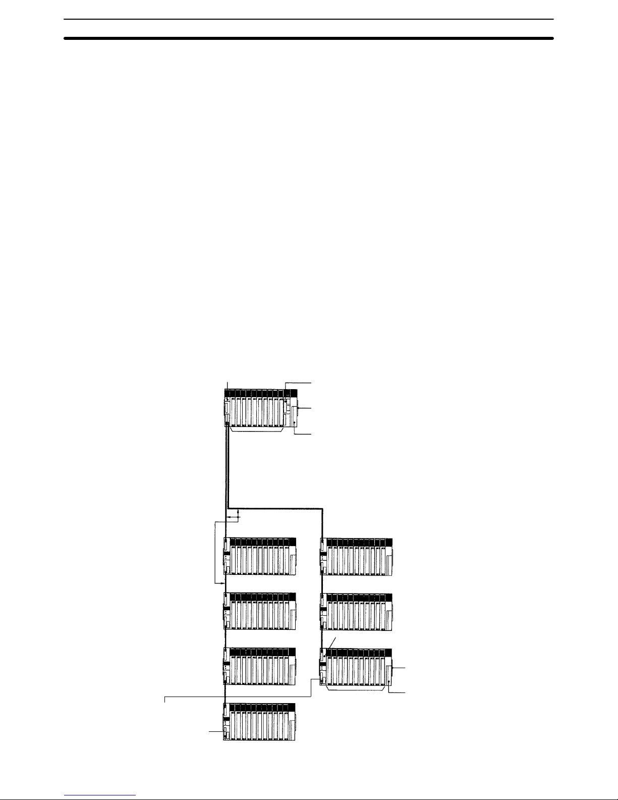
The
following figure shows an assembled CV
-series CPU Rack and seven Ex
-
pansion
I/O Racks. Up to seven Expansion I/O Racks may be connected in one
or
two series from the CPU Rack. The total length of I/O Connecting Cable must
be
50 m or less for each series and a T
ermination Resistance Unit must be be
connected to the last Rack or to the unused I/O Control Unit connector.
Units can be mounted to any slot on the Racks shown for them below.
I/O
Control Unit:
CV500-IC201/IC101
CPU: CV500-CPU01-EV1, CV1000-CPU01-EV1,
CV2000-CPU01-EV1, CVM1-CPU01-EV2, CVM1-CPU11-EV2,
or CVM1-CPU21-EV2
CPU Backplane: CV500-BC031/051/101
Power Supply Unit: CV500-PS221/PS21
1 or CVM1-P
A208
I/O Interface Unit
CV500-II201
I/O Backplane
CV500-BI042/062/112
Power Supply Unit
CV500-PS221/PS211
or CVM1-P
A208
3, 5, or 10 slots
SYSMAC NET Link Units
SYSMAC LINK Units
SYSMAC BUS/2 Masters
Personal Computer Units
BASIC Units
C500 I/O Units
C500 Special I/O Units
SYSMAC BUS Masters
I/O Connecting Cable
CV500-CNjj
2
(50 m max. total length
for 1 series)
4/6/11 slots
C500 I/O Units
C500 Special I/O Units
SYSMAC BUS Masters
T
ermination Resistance Unit:
CV500-TER01
(T
wo included with CV500-IC101/201
I/O Control Unit.)
Systems with only
CV-series Expansion I/O
Racks
System Configuration Section 2-1
17
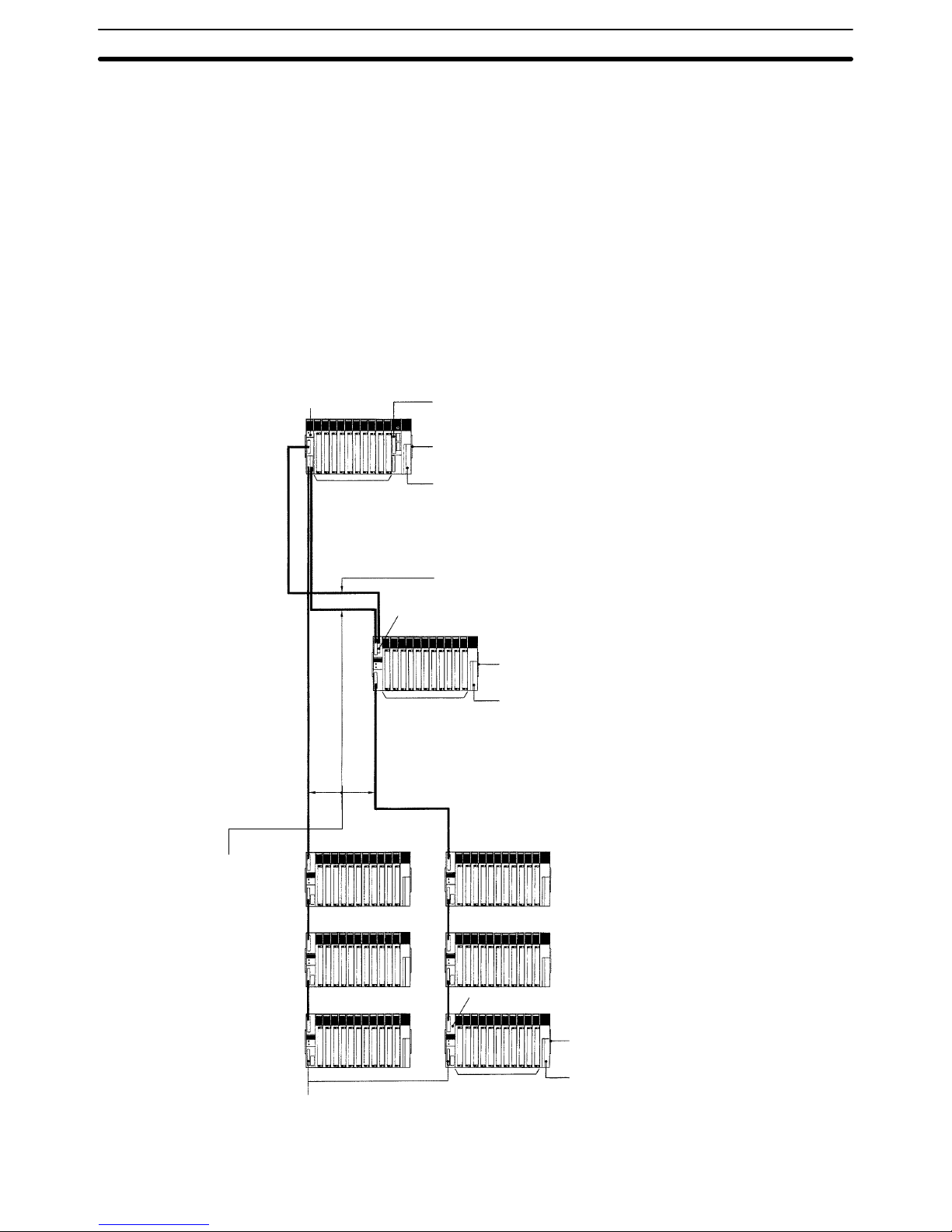
When nine or more CPU Bus Units (Temperature Controller Data Link Units,
SYSMAC
NET Link Units, SYSMAC LINK Units, SYSMAC BUS/2 Remote I/O
Master Units, Ethernet Units,
BASIC Units, and Personal Computer Units) are
required
in a System, the CPU Rack may be extended by connecting an Expan
-
sion CPU Rack to enable mounting up to 16 CPU Bus Units.
Only
one Expansion CPU Rack may be connected to a CPU Rack. A system that
includes
an Expansion CPU Rack can be extended by connecting up to six Ex
-
pansion
I/O Racks.
The Expansion I/O Racks may be connected in one or two
series from the CPU Rack. The total length of I/O Connecting Cable must be
50 m or less for each series and a Termination Resistance Unit must be connected to the last Rack or to the unused I/O Control Unit connector.
Using
an Expansion CPU Rack does not increase the maximum
I/O capacity of
the PC; it only increases the number of CPU Bus Units that can be used.
Units can be mounted to any slot on the Racks shown for them below.
CPU
Backplane: CV500-BC031/051/101
Power Supply Unit: CV500-PS221/PS21
1 or
CVM1-PA208
CPU Connecting Cable
CV500-CNjj1
Expansion CPU Backplane CV500-BI1
11
Power Supply Unit:
CV500-PS221/PS21
1 or CVM1-P
A208
I/O Connecting Cable
CV500-CNjj
2
(50 m max. total
length for 1 series)
T
ermination Resistance Unit CV500-TER01
(T
wo included with CV500-IC101/201 I/O Control Unit.)
I/O Backplane
CV500-BI042/062/112
4/6/11 slots
C500 I/O Units
C500 Special I/O Units
SYSMAC BUS Masters
I/O Interface Unit
CV500-II101
I/O Interface Unit
(CV500-II201)
I/O Control Unit: CV500-IC101
CPU: CV500-CPU01-EV1, CV1000-CPU01-EV1,
CV2000-CPU01-EV1, CVM1-CPU01-EV2, CVM1-CPU1
1-EV2, or
CVM1-CPU21-EV2
3, 5, or 10 slots
SYSMAC NET Link Units
SYSMAC LINK Units
SYSMAC BUS/2 Masters
Personal Computer Units
BASIC Units
C500 I/O Units
C500 Special I/O Units
SYSMAC BUS Masters
11 slots
SYSMAC NET Link Units
SYSMAC LINK Units
SYSMAC BUS/2 Masters
Personal Computer Units
BASIC Units
C500 I/O Units
C500 Special I/O Units
SYSMAC BUS Masters
Power Supply Unit:
CV500-PS221/PS21
1 or CVM1-P
A208
Systems with an Expansion
CPU Rack
System Configuration Section 2-1
 Loading...