


Cat. No. W343-E1-07
SYSMAC
CS/CJ Series
CS1W-ETN01 (10Base-5)
CS1W-ETN11 (10Base-T)
CJ1W-ETN11 (10Base-T)
Ethernet Units
OPERATION MANUAL

CS1W-ETN01 (10Base-5) CS1W-ETN11 (10Base-T) CJ1W-ETN11 (10Base-T) Ethernet Units
Operation Manual
Revised January 2008

iv

Notice:
r
f
OMRON products are manufactured for use according to proper procedures by a qualified operator
and only for the purposes described in this manual.
The following conventions are used to indicate and classify precautions in this manual. Always heed
the information provided with them. Failure to heed precautions can result in injury to people or damage to property.
!DANGER Indicates an imminently hazardous situation which, if not avoided, will result in death or
serious injury. Additionally, there may be severe property damage.
!WARNING Indicates a potentially hazardous situation which, if not avoided, could result in death or
serious injury. Additionally, there may be severe property damage.
!Caution Indicates a potentially hazardous situation which, if not avoided, may result in minor or
moderate injury, or property damage.
OMRON Product References
All OMRON products are capitalized in this manual. The word “Unit” is also capitalized when it refers to
an OMRON product, regardless of whether or not it appears in the proper name of the product.
The abbreviation “Ch,” which appears in some displays and on some OMRON products, often means
“word” and is abbreviated “Wd” in documentation in this sense.
The abbreviation “PC” means Programmable Controller and is not used as an abbreviation for anything
else.
Visual Aids
The following headings appear in the left column of the manual to help you locate different types of
information.
OMRON, 2000
All rights reserved. No part of this publication may be reproduced, stored in a retrieval system, or transmitted, in any form, o
by any means, mechanical, electronic, photocopying, recording, or otherwise, without the prior written permission o
OMRON.
No patent liability is assumed with respect to the use of the information contained herein. Moreover, because OMRON is constantly striving to improve its high-quality products, the information contained in this manual is subject to change without
notice. Every precaution has been taken in the preparation of this manual. Nevertheless, OMRON assumes no responsibility
for errors or omissions. Neither is any liability assumed for damages resulting from the use of the information contained in
this publication.
Note Indicates information of particular interest for efficient and convenient opera-
tion of the product.
1,2,3...
1. Indicates lists of one sort or another, such as procedures, checklists, etc.
v

vi

TABLE OF CONTENTS
PRECAUTIONS . . . . . . . . . . . . . . . . . . . . . . . . . . . . . . . . xvii
1 Intended Audience . . . . . . . . . . . . . . . . . . . . . . . . . . . . . . . . . . . . . . . . . . . . . . . . . xviii
2 General Precautions . . . . . . . . . . . . . . . . . . . . . . . . . . . . . . . . . . . . . . . . . . . . . . . . xviii
3 Safety Precautions. . . . . . . . . . . . . . . . . . . . . . . . . . . . . . . . . . . . . . . . . . . . . . . . . . xviii
4 Operating Environment Precautions . . . . . . . . . . . . . . . . . . . . . . . . . . . . . . . . . . . . xix
5 Application Precautions . . . . . . . . . . . . . . . . . . . . . . . . . . . . . . . . . . . . . . . . . . . . . xix
6 Conformance to EC Directives . . . . . . . . . . . . . . . . . . . . . . . . . . . . . . . . . . . . . . . . xxi
SECTION 1
Features and System Configuration . . . . . . . . . . . . . . . . 1
1-1 Features . . . . . . . . . . . . . . . . . . . . . . . . . . . . . . . . . . . . . . . . . . . . . . . . . . . . . . . . . . 2
1-2 System Configuration . . . . . . . . . . . . . . . . . . . . . . . . . . . . . . . . . . . . . . . . . . . . . . . 3
1-3 Devices Required in a Network . . . . . . . . . . . . . . . . . . . . . . . . . . . . . . . . . . . . . . . 4
1-4 Related Programming Devices . . . . . . . . . . . . . . . . . . . . . . . . . . . . . . . . . . . . . . . . 6
1-5 Specifications . . . . . . . . . . . . . . . . . . . . . . . . . . . . . . . . . . . . . . . . . . . . . . . . . . . . . 7
1-6 Software Configuration . . . . . . . . . . . . . . . . . . . . . . . . . . . . . . . . . . . . . . . . . . . . . . 10
1-7 IP Addresses . . . . . . . . . . . . . . . . . . . . . . . . . . . . . . . . . . . . . . . . . . . . . . . . . . . . . . 12
1-8 Precautions . . . . . . . . . . . . . . . . . . . . . . . . . . . . . . . . . . . . . . . . . . . . . . . . . . . . . . . 14
SECTION 2
Communications Functions . . . . . . . . . . . . . . . . . . . . . . . 15
2-1 Communications Functions. . . . . . . . . . . . . . . . . . . . . . . . . . . . . . . . . . . . . . . . . . . 16
2-2 FINS Communications . . . . . . . . . . . . . . . . . . . . . . . . . . . . . . . . . . . . . . . . . . . . . . 18
2-3 Socket Services . . . . . . . . . . . . . . . . . . . . . . . . . . . . . . . . . . . . . . . . . . . . . . . . . . . . 19
2-4 FTP Server . . . . . . . . . . . . . . . . . . . . . . . . . . . . . . . . . . . . . . . . . . . . . . . . . . . . . . . 21
2-5 Mail . . . . . . . . . . . . . . . . . . . . . . . . . . . . . . . . . . . . . . . . . . . . . . . . . . . . . . . . . . . . .21
SECTION 3
Installation and Initial Setup . . . . . . . . . . . . . . . . . . . . . . 23
3-1 Before Operation. . . . . . . . . . . . . . . . . . . . . . . . . . . . . . . . . . . . . . . . . . . . . . . . . . . 24
3-2 Overview of Startup Procedure . . . . . . . . . . . . . . . . . . . . . . . . . . . . . . . . . . . . . . . . 26
3-3 Unit Components . . . . . . . . . . . . . . . . . . . . . . . . . . . . . . . . . . . . . . . . . . . . . . . . . . 28
3-4 Switch Settings . . . . . . . . . . . . . . . . . . . . . . . . . . . . . . . . . . . . . . . . . . . . . . . . . . . . 33
3-5 Mounting to a PC . . . . . . . . . . . . . . . . . . . . . . . . . . . . . . . . . . . . . . . . . . . . . . . . . . 37
3-6 Connecting to the Network . . . . . . . . . . . . . . . . . . . . . . . . . . . . . . . . . . . . . . . . . . . 39
3-7 Creating an I/O Table . . . . . . . . . . . . . . . . . . . . . . . . . . . . . . . . . . . . . . . . . . . . . . . 45
3-8 Creating Routing Tables . . . . . . . . . . . . . . . . . . . . . . . . . . . . . . . . . . . . . . . . . . . . . 46
3-9 System Setup. . . . . . . . . . . . . . . . . . . . . . . . . . . . . . . . . . . . . . . . . . . . . . . . . . . . . . 51
3-10 Creating an IP Address Table . . . . . . . . . . . . . . . . . . . . . . . . . . . . . . . . . . . . . . . . . 52
3-11 Creating an IP Router Table . . . . . . . . . . . . . . . . . . . . . . . . . . . . . . . . . . . . . . . . . . 52
3-12 Checking Communications . . . . . . . . . . . . . . . . . . . . . . . . . . . . . . . . . . . . . . . . . . . 53
vii

TABLE OF CONTENTS
SECTION 4
System Setup and Memory Allocations. . . . . . . . . . . . . . 57
4-1 Allocated Words . . . . . . . . . . . . . . . . . . . . . . . . . . . . . . . . . . . . . . . . . . . . . . . . . . 58
4-2 CPU Bus Unit System Setup . . . . . . . . . . . . . . . . . . . . . . . . . . . . . . . . . . . . . . . . . 59
4-3 CIO Area Allocations . . . . . . . . . . . . . . . . . . . . . . . . . . . . . . . . . . . . . . . . . . . . . . 67
4-4 DM Area Allocations. . . . . . . . . . . . . . . . . . . . . . . . . . . . . . . . . . . . . . . . . . . . . . . 73
SECTION 5
FINS Communications . . . . . . . . . . . . . . . . . . . . . . . . . . . 79
5-1 Overview of FINS Communications . . . . . . . . . . . . . . . . . . . . . . . . . . . . . . . . . . . 80
5-2 Procedure Before Using FINS Communications. . . . . . . . . . . . . . . . . . . . . . . . . . 82
5-3 Sending Commands From a PC. . . . . . . . . . . . . . . . . . . . . . . . . . . . . . . . . . . . . . . 83
5-4 Sending Commands From a Host Computer. . . . . . . . . . . . . . . . . . . . . . . . . . . . . 96
5-5 FINS Server . . . . . . . . . . . . . . . . . . . . . . . . . . . . . . . . . . . . . . . . . . . . . . . . . . . . . . 102
SECTION 6
Socket Services. . . . . . . . . . . . . . . . . . . . . . . . . . . . . . . . . . 103
6-1 Overview . . . . . . . . . . . . . . . . . . . . . . . . . . . . . . . . . . . . . . . . . . . . . . . . . . . . . . . . 104
6-2 Using Socket Services with Socket Service Request Switches. . . . . . . . . . . . . . . 112
6-3 Using Socket Services with CMND(490) . . . . . . . . . . . . . . . . . . . . . . . . . . . . . . . 139
SECTION 7
FTP Server . . . . . . . . . . . . . . . . . . . . . . . . . . . . . . . . . . . . . 161
7-1 Overview . . . . . . . . . . . . . . . . . . . . . . . . . . . . . . . . . . . . . . . . . . . . . . . . . . . . . . . . 162
7-2 Setting Login Names and Passwords. . . . . . . . . . . . . . . . . . . . . . . . . . . . . . . . . . . 163
7-3 Using File Memory . . . . . . . . . . . . . . . . . . . . . . . . . . . . . . . . . . . . . . . . . . . . . . . . 163
7-4 FTP Server Application Example . . . . . . . . . . . . . . . . . . . . . . . . . . . . . . . . . . . . . 167
7-5 Using FTP Commands. . . . . . . . . . . . . . . . . . . . . . . . . . . . . . . . . . . . . . . . . . . . . . 168
7-6 UNIX Application Example . . . . . . . . . . . . . . . . . . . . . . . . . . . . . . . . . . . . . . . . . 174
SECTION 8
Mail . . . . . . . . . . . . . . . . . . . . . . . . . . . . . . . . . . . . . . . . . . . 177
8-1 Overview of Mail Function . . . . . . . . . . . . . . . . . . . . . . . . . . . . . . . . . . . . . . . . . . 178
8-2 Sending Mail . . . . . . . . . . . . . . . . . . . . . . . . . . . . . . . . . . . . . . . . . . . . . . . . . . . . . 182
8-3 Mail Example. . . . . . . . . . . . . . . . . . . . . . . . . . . . . . . . . . . . . . . . . . . . . . . . . . . . . 182
SECTION 9
Testing Communications . . . . . . . . . . . . . . . . . . . . . . . . . 185
9-1 Communications Testing Functions . . . . . . . . . . . . . . . . . . . . . . . . . . . . . . . . . . . 186
9-2 PING Command . . . . . . . . . . . . . . . . . . . . . . . . . . . . . . . . . . . . . . . . . . . . . . . . . . 186
9-3 Internode Test . . . . . . . . . . . . . . . . . . . . . . . . . . . . . . . . . . . . . . . . . . . . . . . . . . . . 187
viii

TABLE OF CONTENTS
SECTION 10
Troubleshooting . . . . . . . . . . . . . . . . . . . . . . . . . . . . . . . . 191
10-1 Troubleshooting with Indicators . . . . . . . . . . . . . . . . . . . . . . . . . . . . . . . . . . . . . . . 192
10-2 Error Status . . . . . . . . . . . . . . . . . . . . . . . . . . . . . . . . . . . . . . . . . . . . . . . . . . . . . . . 194
10-3 Error Log. . . . . . . . . . . . . . . . . . . . . . . . . . . . . . . . . . . . . . . . . . . . . . . . . . . . . . . . . 194
10-4 Error Log Error Codes . . . . . . . . . . . . . . . . . . . . . . . . . . . . . . . . . . . . . . . . . . . . . . 195
10-5 Troubleshooting Procedures . . . . . . . . . . . . . . . . . . . . . . . . . . . . . . . . . . . . . . . . . . 197
10-6 Troubleshooting with Response Codes . . . . . . . . . . . . . . . . . . . . . . . . . . . . . . . . . . 207
10-7 Results Storage Area Response Codes . . . . . . . . . . . . . . . . . . . . . . . . . . . . . . . . . . 210
SECTION 11
FINS Commands Addressed to Ethernet Units . . . . . . . 213
11-1 Command Codes and Response Codes. . . . . . . . . . . . . . . . . . . . . . . . . . . . . . . . . . 214
11-2 Socket Applications . . . . . . . . . . . . . . . . . . . . . . . . . . . . . . . . . . . . . . . . . . . . . . . . 215
11-3 Command/Response Reference . . . . . . . . . . . . . . . . . . . . . . . . . . . . . . . . . . . . . . . 217
Appendices
A Network Installation . . . . . . . . . . . . . . . . . . . . . . . . . . . . . . . . . . . . . . . . . . . . . . . . 251
B Ethernet Network Parameters . . . . . . . . . . . . . . . . . . . . . . . . . . . . . . . . . . . . . . . . 261
C Buffer Configuration . . . . . . . . . . . . . . . . . . . . . . . . . . . . . . . . . . . . . . . . . . . . . . . 263
D TCP Status Transitions . . . . . . . . . . . . . . . . . . . . . . . . . . . . . . . . . . . . . . . . . . . . . . 265
E Auxiliary Area Data . . . . . . . . . . . . . . . . . . . . . . . . . . . . . . . . . . . . . . . . . . . . . . . . 267
F CPU Bus Unit Allocations in the CPU Unit . . . . . . . . . . . . . . . . . . . . . . . . . . . . . 269
G ASCII Characters . . . . . . . . . . . . . . . . . . . . . . . . . . . . . . . . . . . . . . . . . . . . . . . . . . 277
H Dimensions . . . . . . . . . . . . . . . . . . . . . . . . . . . . . . . . . . . . . . . . . . . . . . . . . . . . . . . 279
I Maintenance . . . . . . . . . . . . . . . . . . . . . . . . . . . . . . . . . . . . . . . . . . . . . . . . . . . . . . 283
J Inspections . . . . . . . . . . . . . . . . . . . . . . . . . . . . . . . . . . . . . . . . . . . . . . . . . . . . . . . 285
Index. . . . . . . . . . . . . . . . . . . . . . . . . . . . . . . . . . . . . . . . . . 287
Revision History . . . . . . . . . . . . . . . . . . . . . . . . . . . . . . . . 293
ix


About this Manual:
This manual describes the installation and operation of the SYSMAC CS-series CS1W-ETN01
(10Base-5) and CS1W-ETN11 (10Base-T) Ethernet Units and the CJ-series CJ1W-ETN11 (10Base-T)
Ethernet Unit, and includes the sections described on the next page.
An Ethernet Unit is classified and treated as a CPU Bus Unit in PC processing.
This manual is based on Ethernet* networks comprised of Ethernet Unit nodes and UNIX* host computer nodes. Although details can vary, theoretically any device supporting the same Ethernet protocols as the Ethernet Unit can form nodes on the network.
Note *Ethernet is a trademark of the Xerox Corporation. UNIX is a registered trademark of USL.
Please read this manual and all related manuals listed in the following table carefully and be sure you
understand the information provided before attempting to install and operate an Ethernet Unit.
Name Cat. No. Contents
SYSMAC CS/CJ-series
CS1W-ETN01/ETN11
CJ1W-ETN11
Ethernet Units
Operation Manual
(this manual)
SYSMAC CS/CJ-series
CS1W-ETN21
CJ1W-ETN21
Ethernet Units
Operation Manual
(Construction of Networks)
SYSMAC CS/CJ-series
CS1W-ETN21
CJ1W-ETN21
Ethernet Units
Operation Manual
(Construction of Applications)
SYSMAC CS-series
CS1G/H-CPU@@
Programmable Controllers
Operation Manual
SYSMAC CJ-series
CJ1G-CPU@@
Programmable Controllers
Operation Manual
SYSMAC CS/CJ-series
CS1G/H-CPU@@
CJ1G/H-CPU@@H, CJ1M-CPU@@,
CJ1G-CPU@@
Programmable Controllers
Programming Manual
SYSMAC CS/CJ-series
CS1G/H-CPU@@-EV1, CS1G/H-CPU@@H,
CJ1G/H-CPU@@H, CJ1M-CPU@@,
CJ1G-CPU@@
Programmable Controllers
Instructions Reference Manual
-EV1, CS1G/H-CPU@@H
-EV1, CS1G/H-CPU@@H,
W343-E1-@ Describes the installation and operation of the CS1W-ETN01 (10Base-
5), CS1W-ETN11 (10Base-T), and CJ1W-ETN11 Ethernet Units.
Refer to the CX-Programmer User’s Manual for information on setting
the CPU Bus Unit Setup for the Ethernet Unit.
Refer to the Communications Commands Reference Manual (W342) for
information on FINS commands that can be addressed to CS/CJ-series
CPU Units.
W420-E1-@ Describes the basic settings and FINS communications for the CS1W-
ETN21 (100Base-TX) and CJ1W-ETN21 (100Base-TX) Ethernet Units.
Refer to the Communications Commands Reference Manual (W342) for
information on FINS commands that can be addressed to CS/CJ-series
CPU Units.
W421-E1-@ Provides information for the CS1W-ETN21 (100Base-TX) and CJ1W-
ETN21 (100Base-TX) Ethernet Units on functions such as mail transmission, socket services, automatic clock adjustment, FTP server, and
creating host applications with FINS communications.
W339-E1-@ Provides an outline of and describes the design, installation, mainte-
nance, and other basic operations for the CS-series PCs.
W393-E1-@ Provides an outline of and describes the design, installation, mainte-
nance, and other basic operations for the CJ-series PCs.
W394-E1-@ This manual describes programming and other methods to use the func-
tions of the CS/CJ-series PCs.
W340-E1-@ Describes the ladder diagram programming instructions supported by
CS-series and CJ-series PCs.
xi

About this Manual, Continued
Name Cat. No. Contents
SYSMAC CS/CJ-series
C200H-PRO27-E, CQM1H-PRO01-E
CQM1-PRO01-E
Programming Consoles
Operation Manual
SYSMAC CS/CJ-series
CS1G/H-CPU@@
CS1W-SCB21-V1/41-V1, CS1W-SCU21,
CJ1W-SCU41
Communications Commands
Reference Manual
SYSMAC WS02-CXPC1-EV3
CX-Programmer Ver. 3.1
Operation Manual
SYSMAC CS/CJ-series
CS1W-SCB21-V1/41-V1, CS1W-SCU21
CJ1W-CSU41
Serial Communications Boards and Serial
Communications Units
Operation Manual
-EV1, CJ1G-CPU@@,
This manual contains the following sections.
Section 1 introduces the overall structure of an Ethernet network, outlines the features of the Ethernet
Unit, describes the communications protocols used by an Ethernet network, and provides basic precautions for use of an Ethernet network.
Section 2 provides an overview of the communications functions that can be used with the Ethernet
Unit.
Section 3 explains how to install the Ethernet Unit and make the initial settings required for operation.
Section 4 explains the system setup and the words allocated in the CIO Area and the DM Area for
Ethernet Unit operations.
Section 5 provides information on communicating on Ethernet networks and interconnected networks
using FINS commands. The information provided in the section deals only with FINS communications
in reference to Ethernet Units. FINS commands issued from a PC are sent via the SEND(090),
RECV(098), and CMND(490) instructions programmed into the user ladder-diagram program. Refer to
the CS/CJ-series CS1G/H-CPU@@
ence Manual (W340) for further details on programming these instructions.
Section 6 describes the functionality provided by the Ethernet Unit via the socket services.
Section 7 describes the functions provided by the FTP server.
Section 8 explains the Ethernet Unit’s mail function.
Section 9 describes functions that allow you to test communications.
Section 10 describes information and procedures that can be used to troubleshoot problems that
sometimes occur with Ethernet Unit and Ethernet communications.
Section 11 describes the FINS commands that can be sent to an Ethernet Unit and the responses that
are returned by the Ethernet Unit.
Var ious Appendices are provided for reference. Refer to the table of contents for a list of the appendices.
W341-E1-@ Provides information on how to program and operate CS/CJ-series PCs
using a Programming Console.
W342-E1-@ Describes the C-series (Host Link) and FINS communications com-
mands used with CS/CJ-series PCs.
W414-E1-@ Provide information on how to use the CX-Programmer, a programming
device that supports the CS/CJ-series PCs, and the CX-Net contained
within CX-Programmer.
W336-E1-@ Describes the use of Serial Communications Units and Boards to per-
form serial communications with external devices, including the usage
of standard system protocols for OMRON products.
-E, CJ1G-CPU@@ Programmable Controllers Instruction Refer-
!WARNING Failure to read and understand the information provided in this manual may result in per-
sonal injury or death, damage to the product, or product failure. Please read each section
in its entirety and be sure you understand the information provided in the section and
related sections before attempting any of the procedures or operations given.
xii

Read and Understand this Manual
Please read and understand this manual before using the product. Please consult your OMRON
representative if you have any questions or comments.
Warranty and Limitations of Liability
WARRANTY
OMRON's exclusive warranty is that the products are free from defects in materials and workmanship for a
period of one year (or other period if specified) from date of sale by OMRON.
OMRON MAKES NO WARRANTY OR REPRESENTATION, EXPRESS OR IMPLIED, REGARDING NONINFRINGEMENT, MERCHANTABILITY, OR FITNESS FOR PARTICULAR PURPOSE OF THE
PRODUCTS. ANY BUYER OR USER ACKNOWLEDGES THAT THE BUYER OR USER ALONE HAS
DETERMINED THAT THE PRODUCTS WILL SUITABLY MEET THE REQUIREMENTS OF THEIR
INTENDED USE. OMRON DISCLAIMS ALL OTHER WARRANTIES, EXPRESS OR IMPLIED.
LIMITATIONS OF LIABILITY
OMRON SHALL NOT BE RESPONSIBLE FOR SPECIAL, INDIRECT, OR CONSEQUENTIAL DAMAGES,
LOSS OF PROFITS OR COMMERCIAL LOSS IN ANY WAY CONNECTED WITH THE PRODUCTS,
WHETHER SUCH CLAIM IS BASED ON CONTRACT, WARRANTY, NEGLIGENCE, OR STRICT
LIABILITY.
In no event shall the responsibility of OMRON for any act exceed the individual price of the product on which
liability is asserted.
IN NO EVENT SHALL OMRON BE RESPONSIBLE FOR WARRANTY, REPAIR, OR OTHER CLAIMS
REGARDING THE PRODUCTS UNLESS OMRON'S ANALYSIS CONFIRMS THAT THE PRODUCTS
WERE PROPERLY HANDLED, STORED, INSTALLED, AND MAINTAINED AND NOT SUBJECT TO
CONTAMINATION, ABUSE, MISUSE, OR INAPPROPRIATE MODIFICATION OR REPAIR.
xiii

Application Considerations
SUITABILITY FOR USE
OMRON shall not be responsible for conformity with any standards, codes, or regulations that apply to the
combination of products in the customer's application or use of the products.
At the customer's request, OMRON will provide applicable third party certification documents identifying
ratings and limitations of use that apply to the products. This information by itself is not sufficient for a
complete determination of the suitability of the products in combination with the end product, machine,
system, or other application or use.
The following are some examples of applications for which particular attention must be given. This is not
intended to be an exhaustive list of all possible uses of the products, nor is it intended to imply that the uses
listed may be suitable for the products:
• Outdoor use, uses involving potential chemical contamination or electrical interference, or conditions or
uses not described in this manual.
• Nuclear energy control systems, combustion systems, railroad systems, aviation systems, medical
equipment, amusement machines, vehicles, safety equipment, and installations subject to separate
industry or government regulations.
• Systems, machines, and equipment that could present a risk to life or property.
Please know and observe all prohibitions of use applicable to the products.
NEVER USE THE PRODUCTS FOR AN APPLICATION INVOLVING SERIOUS RISK TO LIFE OR
PROPERTY WITHOUT ENSURING THAT THE SYSTEM AS A WHOLE HAS BEEN DESIGNED TO
ADDRESS THE RISKS, AND THAT THE OMRON PRODUCTS ARE PROPERLY RATED AND
INSTALLED FOR THE INTENDED USE WITHIN THE OVERALL EQUIPMENT OR SYSTEM.
PROGRAMMABLE PRODUCTS
OMRON shall not be responsible for the user's programming of a programmable product, or any
consequence thereof.
xiv

Disclaimers
CHANGE IN SPECIFICATIONS
Product specifications and accessories may be changed at any time based on improvements and other
reasons.
It is our practice to change model numbers when published ratings or features are changed, or when
significant construction changes are made. However, some specifications of the products may be changed
without any notice. When in doubt, special model numbers may be assigned to fix or establish key
specifications for your application on your request. Please consult with your OMRON representative at any
time to confirm actual specifications of purchased products.
DIMENSIONS AND WEIGHTS
Dimensions and weights are nominal and are not to be used for manufacturing purposes, even when
tolerances are shown.
PERFORMANCE DATA
Performance data given in this manual is provided as a guide for the user in determining suitability and does
not constitute a warranty. It may represent the result of OMRON's test conditions, and the users must
correlate it to actual application requirements. Actual performance is subject to the OMRON Warranty and
Limitations of Liability.
ERRORS AND OMISSIONS
The information in this manual has been carefully checked and is believed to be accurate; however, no
responsibility is assumed for clerical, typographical, or proofreading errors, or omissions.
xv

xvi

PRECAUTIONS
This section provides general precautions for using the CS/CJ-series Programmable Controllers (PCs) and related devices.
The information contained in this section is important for the safe and reliable application of Programmable
Controllers. You must read this section and understand the information contained before attempting to set up or
operate a PC system.
1 Intended Audience . . . . . . . . . . . . . . . . . . . . . . . . . . . . . . . . . . . . . . . . . . . . . xviii
2 General Precautions . . . . . . . . . . . . . . . . . . . . . . . . . . . . . . . . . . . . . . . . . . . . xviii
3 Safety Precautions. . . . . . . . . . . . . . . . . . . . . . . . . . . . . . . . . . . . . . . . . . . . . . xviii
4 Operating Environment Precautions . . . . . . . . . . . . . . . . . . . . . . . . . . . . . . . . xix
5 Application Precautions . . . . . . . . . . . . . . . . . . . . . . . . . . . . . . . . . . . . . . . . . xix
6 Conformance to EC Directives . . . . . . . . . . . . . . . . . . . . . . . . . . . . . . . . . . . . xxi
xvii

Intended Audience 1
1 Intended Audience
This manual is intended for the following personnel, who must also have
knowledge of electrical systems (an electrical engineer or the equivalent).
• Personnel in charge of installing FA systems.
• Personnel in charge of designing FA systems.
• Personnel in charge of managing FA systems and facilities.
2 General Precautions
The user must operate the product according to the performance specifications described in the operation manuals.
Before using the product under conditions which are not described in the
manual or applying the product to nuclear control systems, railroad systems,
aviation systems, vehicles, combustion systems, medical equipment, amusement machines, safety equipment, and other systems, machines, and equipment that may have a serious influence on lives and property if used
improperly, consult your OMRON representative.
Make sure that the ratings and performance characteristics of the product are
sufficient for the systems, machines, and equipment, and be sure to provide
the systems, machines, and equipment with double safety mechanisms.
This manual provides information for programming and operating the Unit. Be
sure to read this manual before attempting to use the Unit and keep this manual close at hand for reference during operation.
!WARNING It is extremely important that a PC and all PC Units be used for the specified
purpose and under the specified conditions, especially in applications that can
directly or indirectly affect human life. You must consult with your OMRON
representative before applying a PC System to the above-mentioned applications.
3 Safety Precautions
!WARNING Do not attempt to take any Unit apart while the power is being supplied. Doing
so may result in electric shock.
!WARNING Do not touch any of the terminals or terminal blocks while the power is being
supplied. Doing so may result in electric shock.
!WARNING Do not attempt to disassemble, repair, or modify any Units. Any attempt to do
so may result in malfunction, fire, or electric shock.
!WARNING Do not touch the Power Supply Unit while power is being supplied or immedi-
ately after power has been turned OFF. Doing so may result in electric shock.
!Caution Tighten the screws on the terminal block of the AC Power Supply Unit to the
torque specified in the operation manual. The loose screws may result in
burning or malfunction.
xviii

Operating Environment Precautions 4
!Caution Execute online edit only after confirming that no adverse effects will be
caused by extending the cycle time. Otherwise, the input signals may not be
readable.
4 Operating Environment Precautions
!Caution Do not operate the control system in the following places:
• Locations subject to direct sunlight.
• Locations subject to temperatures or humidity outside the range specified
in the specifications.
• Locations subject to condensation as the result of severe changes in tem-
perature.
• Locations subject to corrosive or flammable gases.
• Locations subject to dust (especially iron dust) or salts.
• Locations subject to exposure to water, oil, or chemicals.
• Locations subject to shock or vibration.
!Caution Take appropriate and sufficient countermeasures when installing systems in
the following locations:
• Locations subject to static electricity or other forms of noise.
• Locations subject to strong electromagnetic fields.
• Locations subject to possible exposure to radioactivity.
• Locations close to power supplies.
!Caution The operating environment of the PC System can have a large effect on the
longevity and reliability of the system. Improper operating environments can
lead to malfunction, failure, and other unforeseeable problems with the PC
System. Be sure that the operating environment is within the specified conditions at installation and remains within the specified conditions during the life
of the system. Follow all installation instructions and precautions provided in
the operation manuals.
5 Application Precautions
Observe the following precautions when using the PC System.
!WARNING Always heed these precautions. Failure to abide by the following precautions
could lead to serious or possibly fatal injury.
• Always connect to a ground of 100 Ω or less when installing the Units. Not
connecting to a ground to a ground of 100
shock.
• A ground of 100 Ω or less must be installed when shorting the GR and LG
terminals on the Power Supply Unit.
• Always turn OFF the power supply to the PC before attempting any of the
following. Not turning OFF the power supply may result in malfunction or
electric shock.
Ω or less may result in electric
xix

Application Precautions 5
• Mounting or dismounting I/O Units, CPU Units, Inner Boards, or any
other Units.
• Assembling the Units.
• Setting DIP switches or rotary switches.
• Connecting cables or wiring the system.
!Caution Failure to abide by the following precautions could lead to faulty operation of
the PC or the system, or could damage the PC or PC Units. Always heed
these precautions.
• Fail-safe measures must be taken by the customer to ensure safety in the
event of incorrect, missing, or abnormal signals caused by broken signal
lines, momentary power interruptions, or other causes.
Interlock circuits, limit circuits, and similar safety measures in external cir-
•
cuits (i.e., not in the Programmable Controller) must be provided by the
customer.
• Always use the power supply voltages specified in the operation manuals.
An incorrect voltage may result in malfunction or burning.
• Take appropriate measures to ensure that the specified power with the
rated voltage and frequency is supplied. Be particularly careful in places
where the power supply is unstable. An incorrect power supply may result
in malfunction.
• Install external breakers and take other safety measures against short-cir-
cuiting in external wiring. Insufficient safety measures against short-circuiting may result in burning.
• Be sure that all the mounting screws, terminal screws, and cable connec-
tor screws are tightened to the torque specified in the relevant manuals.
Incorrect tightening torque may result in malfunction.
• Leave the label attached to the Unit when wiring. Removing the label may
result in malfunction if foreign matter enters the Unit.
• Remove the label after the completion of wiring to ensure proper heat dis-
sipation. Leaving the label attached may result in malfunction.
• Use crimp terminals for wiring. Do not connect bare stranded wires
directly to terminals. Connection of bare stranded wires may result in
burning.
• Wire all connections correctly.
• Double-check all wiring and switch settings before turning ON the power
supply. Incorrect wiring may result in burning.
• Mount Units only after checking terminal blocks and connectors com-
pletely.
• Be sure that the terminal blocks, Memory Units, expansion cables, and
other items with locking devices are properly locked into place. Improper
locking may result in malfunction.
• Check the user program for proper execution before actually running it on
the Unit. Not checking the program may result in an unexpected operation.
• Do not lay communications cables near power lines or high-voltage lines.
• Always lay communications cables in ducts.
xx

Conformance to EC Directives 6
• Do not pull on the communications cables or bend the communications
cables beyond their natural limit. Doing either of these may break the
cables.
• Do not place objects on top of the communications cables or other wiring
lines. Doing so may break the cables.
• Before touching a Unit, be sure to first touch a grounded metallic object in
order to discharge any static built-up. Not doing so may result in malfunction or damage.
• When transporting or storing Units, place them in special packing boxes
and do not allow them to be subject to excessive shock or vibration during
transportation.
• Confirm that no adverse effect will occur in the system before attempting
any of the following. Not doing so may result in an unexpected operation.
• Changing the operating mode of the PC.
• Force-setting/force-resetting any bit in memory.
• Changing the present value of any word or any set value in memory.
6 Conformance to EC Directives
6-1 Applicable Directives
• EMC Directives
• Low Voltage Directive
6-2 Concepts
EMC Directives
OMRON devices that comply with EC Directives also conform to the related
EMC standards so that they can be more easily built into other devices or the
overall machine. The actual products have been checked for conformity to
EMC standards (see the following note). Whether the products conform to the
standards in the system used by the customer, however, must be checked by
the customer.
EMC-related performance of the OMRON devices that comply with EC Directives will vary depending on the configuration, wiring, and other conditions of
the equipment or control panel on which the OMRON devices are installed.
The customer must, therefore, perform the final check to confirm that devices
and the overall machine conform to EMC standards.
Note Conformance with the EMC (Electromagnetic Compatibility) standards for
EMS (Electromagnetic Susceptibility) and EMI (Electromagnetic Interference)
vary with the model in the way shown below.
Ethernet Unit EMS EMI
CS1W-ETN01/11 EN61131-2 EN61000-6-4 (Radiated emisCJ1W-ETN11 EN61000-6-2
Low Voltage Directive
Always ensure that devices operating at voltages of 50 to 1,000 VAC and 75
to 1,500 VDC meet the required safety standards for the PC (EN61131-2).
sion: 10-m regulations)
xxi


SECTION 1
Features and System Configuration
This section introduces the overall structure of an Ethernet network, outlines the features of the Ethernet Unit, describes
the communications protocols used by an Ethernet network, and provides basic precautions for use of an Ethernet network.
1-1 Features . . . . . . . . . . . . . . . . . . . . . . . . . . . . . . . . . . . . . . . . . . . . . . . . . . . . . . 2
1-2 System Configuration . . . . . . . . . . . . . . . . . . . . . . . . . . . . . . . . . . . . . . . . . . . 3
1-2-1 Device Configuration . . . . . . . . . . . . . . . . . . . . . . . . . . . . . . . . . . . . 3
1-2-2 Node Connections. . . . . . . . . . . . . . . . . . . . . . . . . . . . . . . . . . . . . . . 3
1-3 Devices Required in a Network . . . . . . . . . . . . . . . . . . . . . . . . . . . . . . . . . . . 4
1-3-1 10Base-5 Ethernet Unit. . . . . . . . . . . . . . . . . . . . . . . . . . . . . . . . . . . 4
1-3-2 10Base-T Ethernet Unit . . . . . . . . . . . . . . . . . . . . . . . . . . . . . . . . . . 5
1-4 Related Programming Devices . . . . . . . . . . . . . . . . . . . . . . . . . . . . . . . . . . . . 6
1-5 Specifications . . . . . . . . . . . . . . . . . . . . . . . . . . . . . . . . . . . . . . . . . . . . . . . . . 7
1-6 Software Configuration . . . . . . . . . . . . . . . . . . . . . . . . . . . . . . . . . . . . . . . . . . 10
1-7 IP Addresses . . . . . . . . . . . . . . . . . . . . . . . . . . . . . . . . . . . . . . . . . . . . . . . . . . 12
1-7-1 IP Address Configuration . . . . . . . . . . . . . . . . . . . . . . . . . . . . . . . . . 12
1-7-2 Allocating IP Addresses . . . . . . . . . . . . . . . . . . . . . . . . . . . . . . . . . . 12
1-7-3 IP Address Settings. . . . . . . . . . . . . . . . . . . . . . . . . . . . . . . . . . . . . . 13
1-7-4 Subnet Masks . . . . . . . . . . . . . . . . . . . . . . . . . . . . . . . . . . . . . . . . . . 13
1-8 Precautions . . . . . . . . . . . . . . . . . . . . . . . . . . . . . . . . . . . . . . . . . . . . . . . . . . . 14
1-8-1 Installation . . . . . . . . . . . . . . . . . . . . . . . . . . . . . . . . . . . . . . . . . . . . 14
1-8-2 Ethernet and IEEE802.3 Standards. . . . . . . . . . . . . . . . . . . . . . . . . . 14
1

Fe at ur es Section 1-1
1-1 Features
Select from 10Base-5 or
10Base-T
Wide-ranging Control
Capability Using Ethernet
Communications by UDP/
IP and TCP/IP
Easy Use of Socket
Services
FINS Message
Communications
(FINS Communications
Service Using UDP/IP)
Three models of Ethernet Unit are provided to support both 10Base-5
(CS1W-ETN01) and 10Base-T (CS1W-ETN11/CJ1W-ETN11) Ethernet transmission media.
The Ethernet Unit enables a Programmable Controller (PC) to support a wide
range of protocols via Ethernet, including data communications by TCP/IP
and UDP/IP socket services, FINS command execution (OMRON’s standard
protocol), FTP file transfers, and SMTP message communications.
The Ethernet Unit supports the standard Ethernet protocols, UDP/IP and
TCP/IP, so it can communicate with other Ethernet devices, workstations, personal computers, and Ethernet Units produced by other manufacturers. It can
utilize up to eight socket ports for the various protocols, allowing it to be
employed in a wide range of applications.
TCP or UDP socket services can be easily accessed either by executing the
CMND(490) instruction or by presetting parameters and then manipulating
dedicated control switches in memory. Presetting parameters eliminates the
need for ladder programs to monitor the completion timing of instructions and
socket service processing, and thereby reduces the work hours involved in
program development.
The Ethernet Unit also supports FINS message communications, OMRON’s
standard communications service, so other OMRON PCs can be accessed by
using SEND(090), RECV(098), and CMND(490) instructions in ladder programs. In addition, the FINS gateway function can be used to allow access to
other PCs on not only the same Ethernet network but also on other networks
such as Controller Link and SYSMAC Link.
File Transfers Between PC
and Host Computer
(FTP Server Function)
E-mail Capability User-defined messages, Unit error information, status information, and so on,
24-VDC Power Supply for
Transceiver
Controller Link Network
Connection
Abundant
Troubleshooting
Functions
The Ethernet Unit has a built-in FTP server function, so any workstation or
personal computer with an FTP client function can be used for reading files
from or writing files to the PC. This enables large amounts of data to be transferred at one time without any need for writing a ladder program.
can be sent from the PC to the mail server as e-mail. This function allows
information generated at the production site to be sent out as e-mail.
For the CS1W-ETN01 (10Base-5), a 24-VDC power supply can be used as
the power supply for the transceiver. The Ethernet Unit voltage output provides for a voltage drop in the transceiver cables, so there is no need to adjust
the power supply voltage.
Ethernet, the information-system network, can be connected to Controller
Link, the control-system network, using the FINS communications service.
This allows a PC on the Controller Link network to be monitored from a PC on
the Ethernet network, and, conversely, for data to be exchanged between a
PC on the Controller Link network and a PC on the Ethernet network.
The Ethernet Unit is provided with a variety of troubleshooting functions for
prompt recovery in case of errors.
• Self-diagnostic function at startup
• PING command for checking remote nodes
• Inter-nodal tests for checking remote nodes
• Error log for recording error history data
• E-mail notification when errors occur
2
System Configuration Section 1-2
1-2 System Configuration
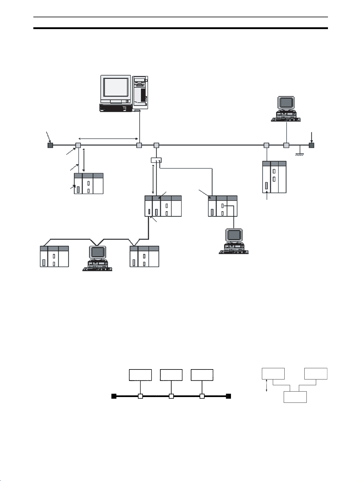
1-2-1 Device Configuration
Workstation or personal computer
CX-Programmer
Ethernet (10 Mbps)
Terminator
Between nodes:
Integral multiples of 2.5 m
500 m/segment max.
10Base-5 coaxial cable
(or 10Base-T twisted-pair cable)
Terminator
Transceiver
Transceiver cable
CS-series
CS1W-ETN01
Ethernet Unit
(10Base-5)
Controller Link network
C200HX/HG/HE PC
50 m max.
CS-series PC
FA computer
100 m max.
CS-series
CS1W-ETN11
Ethernet Unit
(10Base-T)
CS-series
PC
CS-series Controller Link Unit
CS-series PC
CJ-series
CJ1W-ETN11
Ethernet Unit
(10Base-T)
CJ-series
PC
CX-Programmer
Note 1. Transmission distance (from Terminator to Terminator):
500 meters/segment max.
2. When segments are indirectly connected by a repeater: 2.5 km/network
3. Node interval (from transceiver to transceiver): Integral multiples of 2.5 m
4. Transceiver cable length: 50 m max.
Ground
CVM1/CV-series
PC
CVM1/CV Ethernet Unit
(10Base-5)
1-2-2 Node Connections
Minimal Configuration: 1 Segment
10Base-5 10Base-T
Node Node Node
Node Node
1 segment
Hub
3
Devices Required in a Network Section 1-3
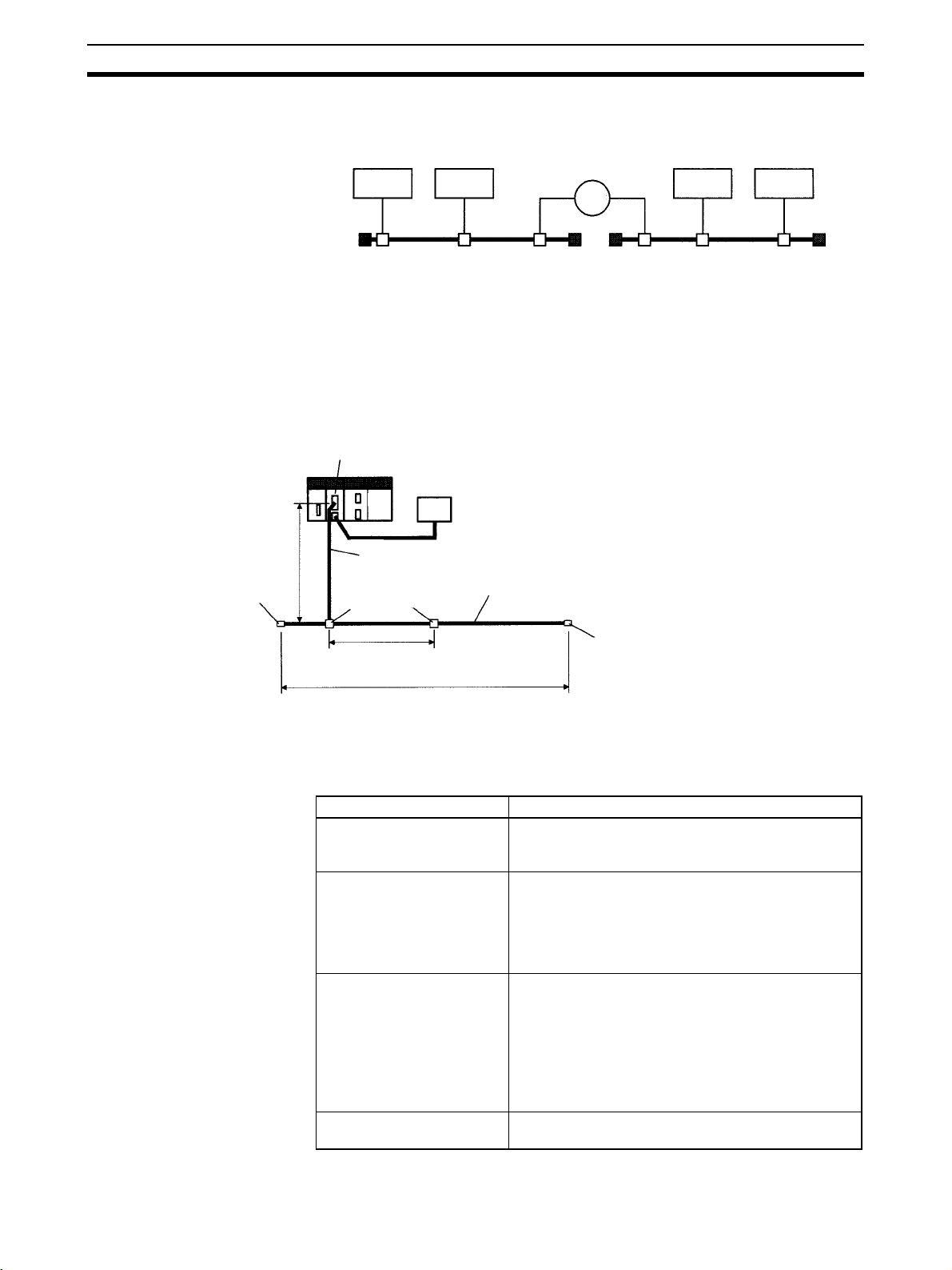
Configuration With
Segment Extension
Use repeaters to extend the distance between nodes or to increase the number of connected nodes.
10Base-5
Node Node
1-3 Devices Required in a Network
1-3-1 10Base-5 Ethernet Unit
The basic configuration of a 10Base-5 Ethernet System consists of a single
coaxial cable together with the transceivers, transceiver cables, nodes, and so
on, that are connected to it. In an Ethernet System, this basic configuration is
called a “segment.”
CS1W-ETN01 Ethernet Unit
24-VDC
power supply
50 m max.
Terminator
(terminating resistance)
Transceiver cable (AUI cable)
Transceivers
Coaxial cable (10Base-5, outer diameter approx. 10 mm)
Repeater
Node Node
2.5 m min.
(multiple of 2.5 m)
Segment (500 m max.)
Number of branch points: 100
Terminator (terminating resistance)
The devices shown in the following table must be obtained to configure a network using a 10Base-5 Ethernet Unit, so prepare them in advance. Use only
devices in the network that conform to IEEE802.3 standards.
Network device Contents
CS-series 10Base-5
Ethernet Unit
(CS1W-ETN01)
24-VDC power supply This is a external 24-VDC power supply for the
Transceiver The transceiver is a device for interfacing between the
Transceiver cable (AUI
cable)
The 10Base-5 Ethernet Unit is a Communications Unit
that connects a CS-series PC to an Ethernet network.
purpose of providing power to the transceivers via
transceiver cable. Use a power supply with an output
current of at least 0.3 A per node. The power is
converted within the Unit to the transceiver power
supply voltage, and is provided to the transceiver.
coaxial cable and the nodes.
Note: The Ethernet Unit can provide a maximum
current of 0.4 A to the transceiver, so use a
transceiver with a current consumption of not more
than 0.4 A. Check with the manufacturer for
information regarding transceiver current
consumption.
This is the cable for connecting between transceivers
and nodes.
4
Devices Required in a Network Section 1-3
Network device Contents
Coaxial cable The coaxial cable comprises the main line of the
Terminator for coaxial cable
(terminating resistance)
Ethernet System.
The Terminators connect to both ends of the coaxial
cable.
Note 1. It is also possible to use 10Base-T twisted-pair cable by connecting the
Ethernet Unit to a 10Base-T conversion adapter.
2. A 24-VDC power supply is required even if a 10Base-T conversion adapter
is used.
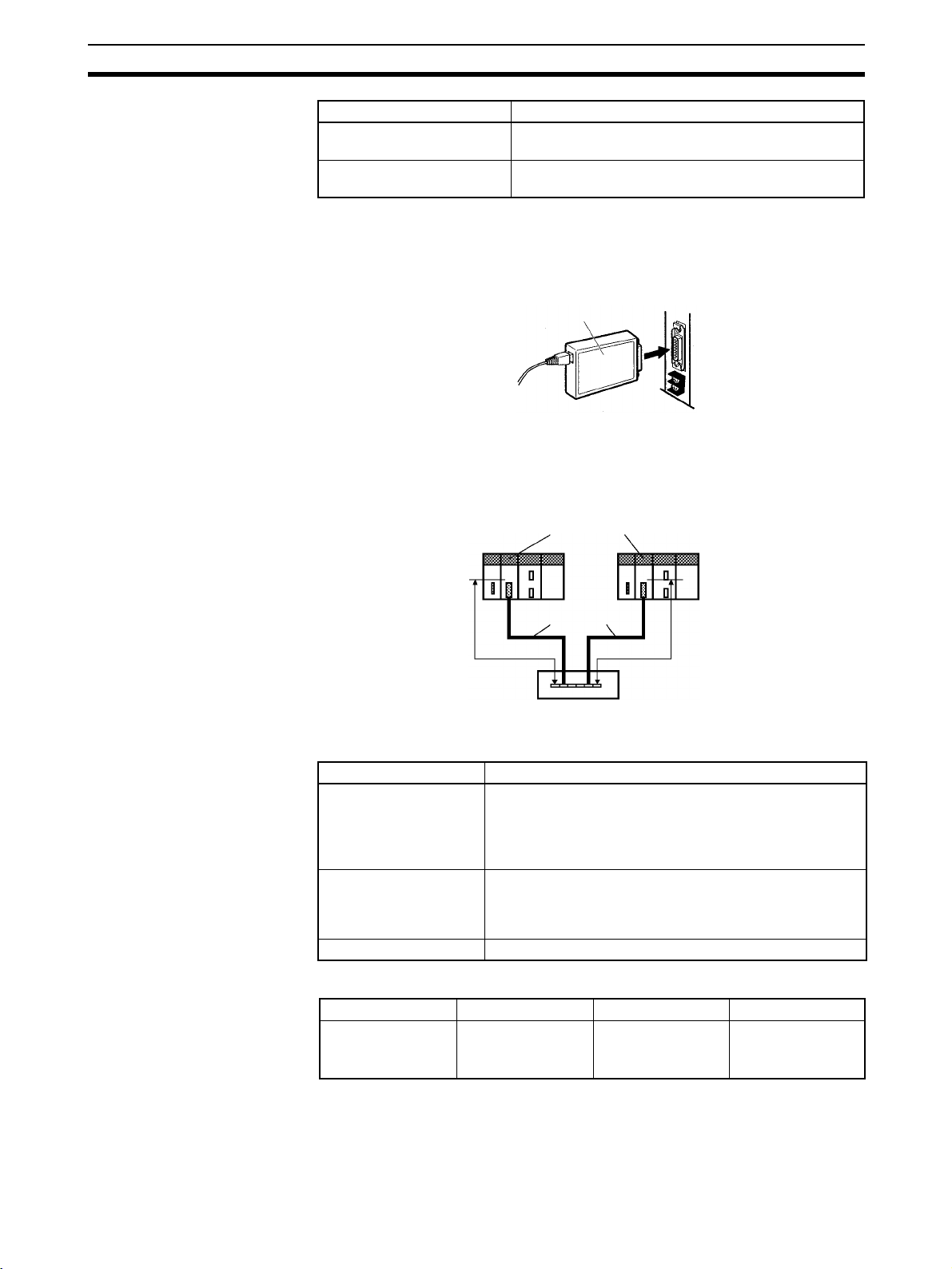
10Base-T conversion adapter
1-3-2 10Base-T Ethernet Unit
The basic configuration of a 10Base-T Ethernet System consists of one hub
to which nodes are attached in star form through twisted-pair cable.
CS1W-ETN11/CJ1W-ETN11 Ethernet Units
Recommended Hub
Twisted-pair cables
100 m max. 100 m max.
Hub
The devices shown in the following table must be obtained to configure a network using a 10Base-T Ethernet Unit, so prepare them in advance.
Network device Contents
CS-series 10Base-T
Ethernet Unit (CS1WETN11) or CJ-series
10Base-T Ethernet Unit
(CJ1W-ETN11)
Twisted-pair cable A twisted-pair cable that connects the 10Base-T Ethernet
Hub A relay devices that connect multiple nodes in as star LAN.
Manufacturer Model number Specifications Inquires
Allied Telesis MR820TLX 9-port hub with
The 10Base-T Ethernet Units are Communications Units
that connect a CS-series or CJ-series PCs to Ethernet
networks.
Unit to the hub. The twisted-pair cable must have an RJ45
Modular Connector attached to each end. Use a category
3, 4, or 5 UTP (unshielded twisted-pair) cable.
10Base-5 backbone port
Allied Telesis
(0120) 86-0442
(in Japan only)
5
Related Programming Devices Section 1-4
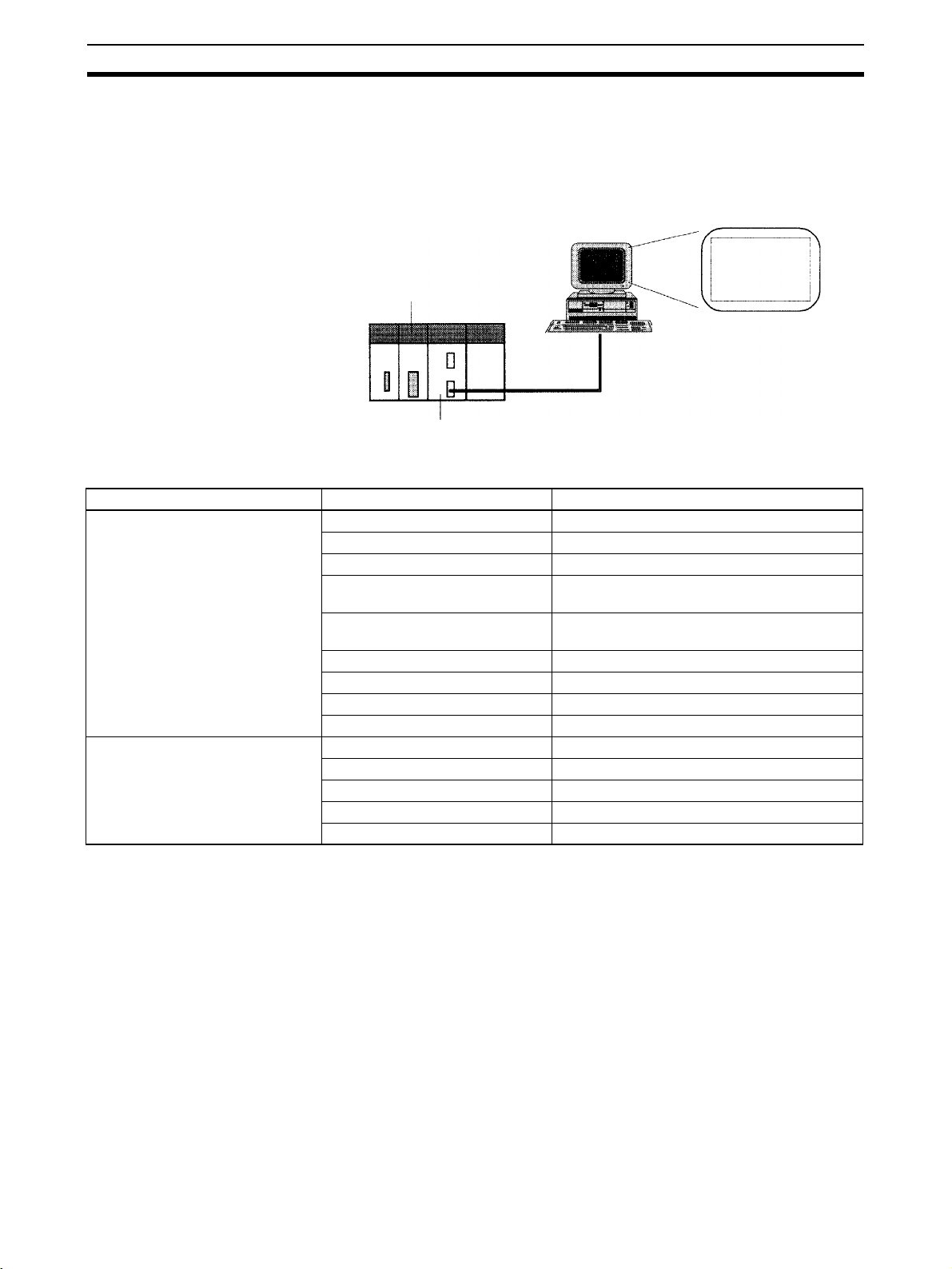
1-4 Related Programming Devices
The Ethernet Unit functions as a node on the Ethernet network. The basic settings for operation are made in the CPU Bus Unit System Setup in the CS/CJseries CPU Unit. Use the CX-Programmer to make the settings.
Personal computer running Windows
CX-Programmer
CPU Bus Unit
System Setup
Ethernet Unit
CS/CJ-series CPU Unit
The following items are included in the System Setup.
Screen Item Default
Setup Screen Broadcast setting All 1 (4.3BSD specifications)
Address conversion method Automatic generation
FINS UDP port number 9600
Local IP address (CJ Series only) 0.0.0.0 (Set the IP address in the allocated
words in the DM Area.)
Subnetwork mask 0.0.0.0 (Uses value corresponding to IP
address class.)
FTP login name CONFIDENTIAL
FTP password Not set.
IP address table Not set.
IP router table Not set.
Mail Setup Screen Mail settings None set.
User-created mail data address Not set.
Local node address Not set.
Destination address Not set.
SMTP server address 0.0.0.0 (Not set.)
Screen
When using the default values that are already stored in the CS/CJ-series
CPU Unit, there is no need to make any settings with the CX-Programmer.
Refer to 4-2 CPU Bus Unit System Setup for details on the above settings.
6

Specifications Section 1-5
1-5 Specifications
CS-series Ethernet Units
Item Specifications
Model number CS1W-ETN01 CS1W-ETN11
Type 10Base-5 10Base-T
Applicable PCs CS-series PCs
Unit classification CS-series CPU Bus Unit
Mounting location CPU Rack or Expansion Rack
Number of Units that can be
mounted
Tr an s fe r
specifications
Current consumption (Unit) 400 mA max. at 5 VDC 400 mA max. at 5 VDC
External power supply Capacity: 0.3 A min. at 24 VDC (per node)
Power supply to transceiver Capacity: 0.4 A at 12 V
Vibration resistance Conforms to JIS 0040.
Shock resistance Conforms to JIS 0041.
Ambient temperature Operating: 0 to 55°C
Humidity 10% to 90% (with no condensation)
Atmosphere Must be free from corrosive gas.
Weight 300 g max.
Dimensions 35 x 130 x 101 mm (W x H x D)
Media access method CSMA/CD
Modulation Baseband
Transmission paths Bus Star
Baud rate 10 Mbps
Transmission media Coaxial cable Unshielded twisted-pair (UTP)
Tr an s mission
distance
Number of connectable nodes
Distance between
nodes
Transceiver cable
length
Segment
length
Distance
between
nodes
4 max. (including Expansion Racks)
cable
500 m max. 100 m max.
2,500 m max. ---
100/segment max. ---
Multiples of 2.5 m ---
50 m max. ---
Inrush current: 2.5 A max.
Permissible voltage fluctuation range:
Recommended power supply: OMRON S82J-series
Voltage fluctuation range: 13.05 to 14.48 VDC
Ripple: 2% p-p
10 to 57 Hz, 0.075-mm amplitude, 57 to 150 Hz, acceleration: 9.8 m/s
directions for 80 minutes each
(Time coefficient; 8 minutes × coefficient factor 10 = total time 80 minutes)
147 m/s
Storage: –20 to 75°C
20.4 to 26.4 VDC (24 VDC –15% to +10%)
2
three times each in X, Y, and Z directions
(24-VDC startup time of 5 ms)
---
---
2
in X, Y, and Z
7

Specifications Section 1-5
CJ-series Ethernet Units
Item Specifications
Model number CJ1W-ETN11
Ty pe 1 0B a s e- T
Applicable PCs CJ-series PCs
Unit classification CJ-series CPU Bus Unit
Mounting location CPU Rack or Expansion Rack
Number of Units that can be mounted 4 max. (including Expansion Racks)
Tr an s fe r
specifications
Current consumption (Unit) 380 mA max. at 5 VDC
Vibration resistance Conforms to JIS 0040.
Shock resistance Conforms to JIS 0041.
Ambient temperature Operating: 0 to 55°C
Humidity 10% to 90% (with no condensation)
Atmosphere Must be free from corrosive gas.
Weight 100 g max.
Dimensions 31 x 90 x 65 mm (W x H x D)
Media access method CSMA/CD
Modulation Baseband
Transmission paths Star
Baud rate 10 Mbps
Transmission media Unshielded twisted-pair (UTP) cable
Transmission
distance
Segment
length
100 m max.
10 to 57 Hz, 0.075-mm amplitude, 57 to 150 Hz, acceleration: 9.8 m/s2 in X, Y,
and Z directions for 80 minutes each
(Time coefficient; 8 minutes × coefficient factor 10 = total time 80 minutes)
2
147 m/s
Storage: –20 to 75°C
three times each in X, Y, and Z directions
8
Specifications Section 1-5
(
)(
)
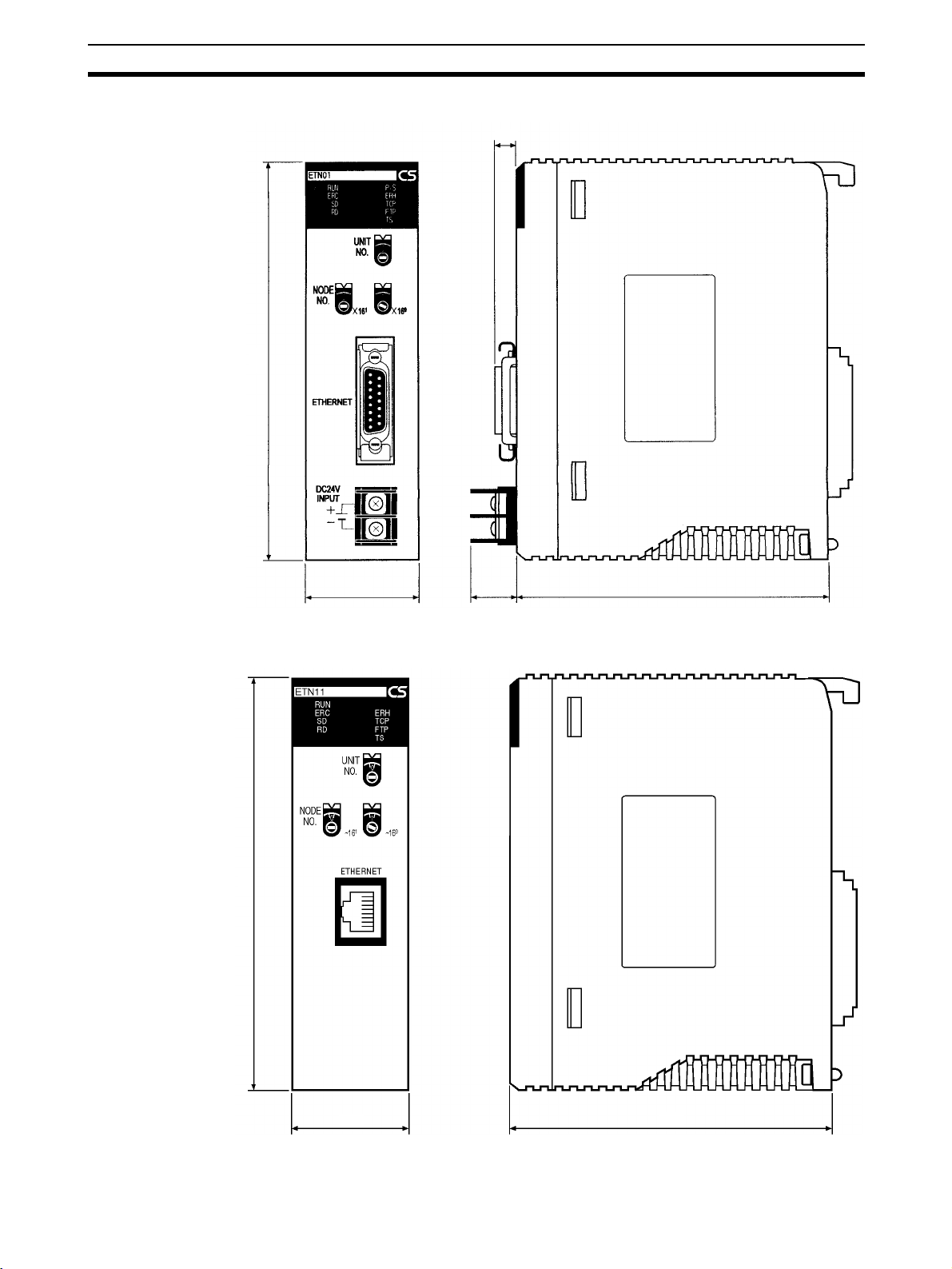
Dimensions
CS1W-ETN01
130
35 15
6.6
101
CS1W-ETN11
130
16.5 including cover
Unit: mm
35 101
(Unit: mm)
9

Software Configuration Section 1-6
t
CJ1W-ETN11
31
ETN11
RUN
ERC SD RD
ERH TCP FTP TS
5
4
UNIT
6
3
7
2
8
1
9
0
A
F
No.
B
E
C
D
5
4
NODE
6
3
7
2
8
1
9
0
A
F
No.
B
E
C
D
1
x16
5
4
6
3
7
2
8
1
9
0
A
F
B
E
C
D
0
x16
90 2.72.7
ETHERNET
1-6 Software Configuration
The software supported by the Ethernet Unit runs in the layers shown in the
following diagram. The components that form the various layers are defined
below the diagram.
65
(Unit: mm)
Memory Card/
EM File Memory
Mail
transmissions
SMTP
TCP
ICMP ARP
FTP
CS/CJ-series PC's CPU Uni
FTP server
Ethernet Unit
FINS Communication
Service
CS/CJ-series PC's CPU
Socket
Services
FINS
UDP
IP
Socket
Services
Ethernet (V2.0)
Ethernet The Version-2.0 Ethernet frame format is used for communications.
IP Internet Protocol: Transfers datagrams to target nodes using IP addresses.
ICMP Internet Control Message Protocol: Supports IP communications by signalling
errors in data transfers.
ARP Address Resolution Protocol: Determines the Ethernet address (i.e., physical
address) by broadcasting based on the target IP address.
UDP User Datagram Protocol: Performs datagram communications. Data resends,
priority control, flow control, and other measures to ensure communications
reliability are not performed for UDP communications, i.e., there is no way of
guaranteeing normal communications without programming special measures
to do so into the user’s application program.
TCP Transmission Control Protocol: Performs communications after establishing a
connection (i.e., a virtual circuit) with the target node to provide a highly reliable communications method.
10

Software Configuration Section 1-6
FINS Factory Interface Network Service: A protocol that sends messages between
PCs on any of various OMRON FA networks. The user must provide measures such as retry processing to ensure that transmitted messages arrive at
the destination node.
SMTP Simple Mail Transfer Protocol: A communications protocol for sending e-mail
by TCP/IP.
FTP File Transfer Protocol: Transfers data files.
11

IP Addresses Section 1-7
1-7 IP Addresses
Ethernet networks use IP addresses for communications. IP addresses (Internet addresses) identify both the Ethernet network and the node (host computer, Ethernet Unit, etc.) on the Ethernet network. IP addresses must be set
and controlled so that they are not duplicated.
1-7-1 IP Address Configuration
IP addresses are made up of 32 bits of binary data divided into four 8-bit fields
called octets. These four octets provide the network number (net ID) and host
number (host ID). The network number identifies the network and the host
number identifies the node (or host) on the network.
The network numbers in an IP addresses are divided into three classes, A, B,
and C, so that the address system can be selected according to the scale of
the network. (Classes D and E are not used.) The configuration of the IP
address for each of these classes is shown in the following diagram.
Class A
Class B
Class C
Class D
Class E
Bit 31
0 Network number (7 bits) Host number (24 bits)
Bit 31
1 Network number (14 bits) Host number (16 bits)
0
Bit 31
1 Network number (21 bits) Host number (8 bits)
1 0
Bit 31
1 1 1 0
Bit 31
1 1 1 1
23
15 00
700
Multicast address
Test address
The number of networks in each class and the number of nodes possible on
the network differ according to the class.
Class Number of networks Number of hosts
Class A Small
Class B Medium
Class C Large
00
00
(Cannot be used.)
00
(Cannot be used.)
24
– 2 max. (16,777,214 max.)
2
16
– 2 max. (65.534 max.)
2
28 – 2 max. (254 max.)
IP addresses are represented by the decimal equivalent of each of the four
octets in the 32-bit address, each separated by a period. For example, the
binary address 10000010 00111010 00010001 00100000 would be represented as 130.58.17.32.
Note The same network number must be set for every node on the same Ethernet
network.
1-7-2 Allocating IP Addresses
IP (Internet Protocol) is a standard communications protocol used throughout
the world and is designed to enable communications between any Ethernet
12

IP Addresses Section 1-7
nodes regardless of the networks on which they exist. To achieve this, network numbers are allocated by the Network Solutions, InterNIC Registration
Services, to ensure that all Ethernet networks have unique numbers regardless of where they exist. The local system administrator is left the responsibility of allocating unique host numbers locally. You therefore should obtain a
network number from the InterNIC Registration Services to ensure uniqueness and allow for future network expansions if required.
1-7-3 IP Address Settings
An IP address must be set for the Ethernet Unit before Ethernet communications can proceed. The IP address is set for each CS-series Ethernet Unit
using the rotary switch on the back of the Unit. For more details, refer to Set-
ting the Local IP Address. The IP address for each CJ-series Ethernet Unit is
set in the DM Area words allocated to CPU Bus Units or the CPU Bus Unit
System Setup using a Programming Device. For more details, refer to
CPU Bus Unit System Setup
or 4-4 DM Area Allocations.
4-2
1-7-4 Subnet Masks
Operation and management of a network may become very difficult if too
many nodes are connected on a single network or if a single organization has
to manage too many network numbers. It can therefore be convenient to
divide a single network up into several subnetworks by using part of the host
number as a subnet number. Internally the network can be treated as a number of subnetworks, but from the outside it acts as a single network and uses
only a single network number.
To establish subnetworks, the host number in the IP address is divided into a
subnet number and a host number by using a setting called the subnet mask.
The subnet mask indicates which part of the host number is to be used as the
subnet number. The user must first determine the number of bits of the host
number to be used as the subnet number and then set the subnet mask
accordingly. All bits in the subnet mask that correspond to the bits in the IP
address used either as the network number or subnet number are set to “1”
and the remaining bits, which will correspond to the bits in the IP address
actually used for the host number, are set to “0”.
The following example shows the subnet mask for an 8-bit subnet number
used in a class-B IP address. This subnet mask is structured as follows:
This would thus be a class-B IP address masked as a class-C IP address, i.e.,
externally it would be allocated a class-B IP address but internally it can be
addressed using class-C IP addresses.
Subnet mask: 11111111 11111111
It is only necessary to set subnet masks if subnetworks are used. If a subnet
mask is not set by the user, a default mask will be set automatically according
to the IP address class to indicate that the entire host number will be used as
the host number, i.e., no bits will be assigned for use as the subnet number.
All nodes on the network that are going to belong to the same subnetwork
must have the same subnet mask.
In this case, the following subnet mask values will be used depending on the
IP address class.
Class Network mask value
Class A 255.0.0.0
Class B 255.255.0.0.0
Class C 255.255.255.0.0.0
11111111 00000000 (FFFFFF00)
13

Precautions Section 1-8
1-8 Precautions
Be sure to observe the following precautions when installing and using an
Ethernet Unit.
1-8-1 Installation
Observe the following precautions when installing an Ethernet System. (Refer
to Section 3 Installation and Initial Setup for details.)
1,2,3... 1. Use transceiver cable that meets IEEE802.3 standards to ensure high
noise resistance.
2. Use a transceiver with a current consumption of not more than 0.4 A per
port.
3. Always turn off the power supply to the PC before connecting or disconnecting the transceiver cable.
4. Be sure not to exceed the current capacity of the Power Supply Unit on the
Rack to which the Ethernet Unit is mounted. The current consumption of
the CS-series Ethernet Units is 400 mA maximum and the current consumption of the CJ-series Ethernet Unit is 380 mA maximum. This value
added to the current consumption of all other Units mounted to the same
Rack must not exceed the capacity of the Power Supply Unit.
5. Do not install the transceiver cables or coaxial cables of the Ethernet System near power supply lines. If installation near possible sources of noise
is unavoidable, install the cables in grounded metal ducts or take other
measure to eliminate noise interference.
1-8-2 Ethernet and IEEE802.3 Standards
The Ethernet Unit was designed based on version-2 Ethernet standards and
not on the international IEEE802.3 standards, which were developed based
on Version-2.0 Ethernet specifications. Although these two sets of standards
are similar, they are not necessarily the same. Particularly, different frame formats are used, making direct communications impossible between systems
that do not support the same standards. Standards for equipment used to
configure networks are the same, allowing IEEE802.3-standard equipment to
be used with the Ethernet Unit. Particularly the transceiver cable for the
IEEE802.3 standards provides superior noise resistance and should be used
for the Ethernet Unit.
Terminology also differs between Version-2.0 Ethernet and IEEE802.3 standards. These differences are shown in the following table. Version-2.0 Ether-
net terminology is used in this manual.
Version-2 Ethernet IEEE802.3
Tr an s c ei v er M AU
Transceiver cable AUI
Ethernet address MAC address
Ethernet 10Base-5/10Base-T
14

SECTION 2
Communications Functions
This section provides an overview of the communications functions that can be used with the Ethernet Unit.
2-1 Communications Functions. . . . . . . . . . . . . . . . . . . . . . . . . . . . . . . . . . . . . . . 16
2-1-1 Ethernet Unit Functions . . . . . . . . . . . . . . . . . . . . . . . . . . . . . . . . . . 17
2-1-2 Socket Ports Used By the Ethernet Unit. . . . . . . . . . . . . . . . . . . . . . 17
2-1-3 Selecting Communications Services. . . . . . . . . . . . . . . . . . . . . . . . . 18
2-2 FINS Communications . . . . . . . . . . . . . . . . . . . . . . . . . . . . . . . . . . . . . . . . . . 18
2-3 Socket Services . . . . . . . . . . . . . . . . . . . . . . . . . . . . . . . . . . . . . . . . . . . . . . . . 19
2-4 FTP Server . . . . . . . . . . . . . . . . . . . . . . . . . . . . . . . . . . . . . . . . . . . . . . . . . . . 21
2-5 Mail . . . . . . . . . . . . . . . . . . . . . . . . . . . . . . . . . . . . . . . . . . . . . . . . . . . . . . . . . 21
15

Communications Functions Section 2-1
2-1 Communications Functions
The following table shows the communications service functions that are
available with the Ethernet Unit.
Function FINS communications Socket services FTP server Mail
Client
to
server
PC to PC --- ---
By executing
SEND(090),
RECV(098),
or CMND(490)
FINS command
By executing
CMND(490) or
manipulating dedicated
control switches in
memory.
Any data
PC to host
computer
By executing
SEND(090),
RECV(098), or
CMND(490)
Host computer (with
FINS Gateway function)
FINS command
Host computer to
PC
By sending FINS
messages from the
host computer.
Host computer
(with FINS Gateway function)
FINS command
Data type FINS commands (vari-
ous commands for I/O
memory communications in the PC, changing the operating mode,
reading and writing
files, and so on)
Maximum data size PC to PC: 1,980 bytes
max.
PC to host computer:
1,980 bytes max.
Host computer to PC:
2,000 bytes max.
Features Enables control of PC
and host computer that
support FINS commands.
Reference Section 5 FINS Com-
munications
At PC: By executing
CMND(490) or
manipulating dedicated
control switches in
memory.
Host computer (without
FINS Gateway function)
(Passive open)
Any data
(Active open)
At PC: By executing
CMND(490) or
manipulating dedicated
control switches in
memory.
Host computer (without FINS Gateway
function)
(Active open)
Any data
(Passive open)
Any data (PC’s internal
I/O memory)
---
FTP commands
executed by
host computer
Host computer
File
DOS files in File Memory (Memory Card or
EM File Memory)
E-mail can be set to be
sent when specified
bits turn ON, when
errors occur, or at
fixed intervals.
Mail server
E-mail
---
User-defined messages, error log information, status
information
1,984 bytes max. No particular limit. User-defined mes-
sages: 1,024 bytes
max.
Communications by
standard TCP/IP and
UDP/IP via Ethernet.
No need to set FINS
addresses.
Section 6 Socket Ser-
Files are read by
means of simple commands and applications from host
computers with FTP
Ethernet Unit status is
obtained by e-mail.
Notification of errors is
received by e-mail.
client functions.
Section 7 FTP Server Section 8 Mail
vices
16

Communications Functions Section 2-1
2-1-1 Ethernet Unit Functions
Function Contents
FINS communications • A SEND(090), RECV(098), or CMND(490) instruction from the PC’s lad-
Socket services The Ethernet Unit supports up to 16 ports (8 TCP ports and 8 UDP ports)
FTP server The FTP server function allows data files to be transferred between a client
Mail The types of data listed below can be sent as e-mail when a dedicated con-
der program is used to send a FINS command to a remote node, and a
response is received.
• A FINS command is received from a remote node. If the command is
addressed to the local Unit, it is processed internally. If it is addressed to
another Unit, a request is made to the CPU Unit and the result is sent
back to the remote node as a response.
• Following the FINS header information, the Ethernet Unit serves as a
gateway for FINS commands and responses between other Communications Units mounted to the same PC.
for socket interface with respect to the ladder program. When this function
is used, communications can be carried out by either TCP or UDP with various devices on the Ethernet network.
This function can be used by either manipulating dedicated control
switches in memory or by executing CMND(490).
1) Manipulating dedicated control switches in memory:
Socket services can be used by first setting the required parameters in
the Socket Service Parameter Area allocated in the DM Area (refer
to4-4 DM Area Allocations) and then turning ON dedicated control
switches in memory.
There is no need to monitor the completion timing for instructions or
socket services, so the work hours involved in developing ladder programs can be reduced.
Only eight socket ports (UDP and TCP combined) can be used with
this method. For any ports that exceed that number, use the
CMND(490) instruction.
2) Using CMND(490)
Socket services can be used by utilizing the CMND(490) instruction to
execute FINS commands. Up to 16 socket ports can be used with
CMND(490).
workstation or personal computer and the PC’s file system (Memory Card
or EM Area).
trol switch in memory is turned ON, when an error occurs, or when a preset
time interval elapses. Any of the following types of data can be specified for
transmission with any of these timing methods. (Refer to Section 8 Mail.)
• User-created data (Data at PC: ASCII, 1,024 bytes max.)
• Error log information (64 records)
• Status information
A mail server must be provided separately in order to use the mail function.
2-1-2 Socket Ports Used By the Ethernet Unit
Port number Application
UDP 9600 Used for FINS. (Can be changed by CPU Bus Unit System Setup.)
TCP 20 Used for FTP server function (for data transfer).
21 Used for FTP server function (for connection).
17

FINS Communications Section 2-2
2-1-3 Selecting Communications Services
Refer to the following guidelines to select the appropriate communications
service to use in a given situation.
To communicate with an
OMRON PC.
To communicate with a host
computer (with the FINS
gateway function enabled).
To perform operations with
an OMRON PC other than
sending or receiving data
(for example, reading or
writing files or changing the
operating mode).
To perform operations
with a host computer (with
the FINS gateway function enabled) other than
sending or receiving data
(for example, reading or
writing files or changing
the operating mode).
To communicate with a
non-OMRON PC.
To communicate with an
OMRON PC within the
socket services system.
To communicate with a host
computer (with the FINS
gateway function disabled).
By manipulating a
dedicated control
switch.
By using CMND(490).
FINS Communications
Socket services
(control switch manipulation)
Socket services (CMND(490))
Refer to
Section 5 FINS Communications.
Refer to
Section 6 Socket Services.
To designate from the host
computer a file transfer
between the PC and the
host computer.
To send e-mail from the PC
to the mail server by any of
the required conditions.
2-2 FINS Communications
FINS commands can be sent to or received from other PCs or computers on
the same Ethernet network by executing SEND(090), RECV(098), or
18
FTP server
Mail Service
Refer to
Section 7 FTP Server.
Refer to Section 8 Mail.

Socket Services Section 2-3
CMND(490) instructions in the ladder-diagram program. This enables control
operations such as the reading and writing of I/O memory between PCs,
mode changes, and file memory operations. (When a FINS message is sent
on an Ethernet network, a UDP/IP header is automatically added to the message.)
The FINS gateway function allows access not only to PCs on the same Ethernet network, but also to PCs on other networks such as SYSMAC LINK or
Controller Link.
Ethernet
CS/CJ-series
CPU Unit
Executing from the host computer FINS commands with UDP/IP headers
added enables various control operations such as the reading and writing of
I/O memory of PCs on the Ethernet network, mode changes, and file memory
operations.
2-3 Socket Services
Ethernet Unit
User program
SEND(090,
RECV(098), or
CMND(490)
CS/CJ-series
CPU Unit
Ethernet Unit Ethernet Unit
Ethernet
Ethernet Unit
By Manipulating
Dedicated Control
Switches
The socket services allow devices on the Ethernet to send and receive various data using the UDP or TCP protocol. There are two ways to use socket
services, as explained below. (For details, refer to Section 6 Socket Services.)
The first way to use socket services is to set the required parameters in the
parameter area allocated in the DM Area, and then to request particular UDP
or TCP socket services by turning ON dedicated control switches in memory.
The Ethernet Unit turns OFF the same bit when the requested process has
been completed. Data that is sent or received is automatically handled
according to the I/O memory locations specified in the parameter area.
19

Socket Services Section 2-3
There is no need to execute the CMND(490) instruction or to monitor the completion timing and actual processing of the instruction, so this helps to simplify
ladder programming.
A total of eight ports (UDP and TCP combined) can be used for socket services.
UNIX computer, etc.
(node with socket services interface)
Ethernet
TCP/UDP protocol
Ethernet Unit
CS/CJ-series
CPU Unit
Socket Service Request Switches
Socket
TCP/UDP
protocol
Ethernet Unit
Parameters
CS/CJ-series
CPU Unit
By Executing CMND(490) The other way to use socket services is to request a UDP or TCP socket ser-
vice by sending a FINS command to the Ethernet Unit by executing
CMND(490) from the CPU Unit. When the Ethernet Unit receives the socket
service request, it returns a response to the CPU Unit to confirm that it
received the request and then begins the requested processing. When the
processing is completed, the results are stored in the Results Storage Area in
the CPU Unit.
Eight TCP ports and eight UDP ports can be used.
20
TCP/UDP protocol
CS/CJ-series
CPU Unit
TCP protocol
UDP protocol
UNIX computer, etc.
(node with socket
services interface)
Ethernet
Ethernet Unit
FINS command
FINS response
Socket
Processing results
Socket interface
Ethernet Unit
Results Storage Area
CS/CJ-series
CPU Unit

FTP Server Section 2-4
2-4 FTP Server
The Ethernet Unit has a built-in FTP server function, so other computers on
the Ethernet can read or write individual files in a Memory Card mounted to
the CPU Unit or in EM file memory. This allows files to be exchanged between
the host computer and the PC, with the host computer functioning as an FTP
client and the PC as an FTP server. For details, refer to Section 7 FTP Server.
Host computer (FTP client)
Ethernet
2-5 Mail
FTP command
CS/CJ-series
CPU Unit
(Host computer to PC) (PC to host computer)
File data
Ethernet Unit
File data
Memory Card or
EM file memory
Memory Card or
EM file memory
Memory Card or
EM file memory
Data such as user-created information (1,024 bytes max. in ASCII), Ethernet
Unit error log information (64 records max.), and status information can be
sent as e-mail to specified addresses.
The e-mail can be sent with any of the following three types of timing. (Simultaneous specification is also possible.)
• When the Mail Send Switch turns ON.
• When an error occurs (when an error log is recorded.)
• At regular intervals.
This enables periodic e-mail and error messages to be sent from the PC to
the mail server.
Mail server
Ethernet
Mail
CS/CJ-series
CPU Unit
Ethernet Unit
Note 1. A mail server is required in order to use the mail function.
2. Mail server settings require specialized knowledge, so they should always
be handled by the network administrator.
3. Be sure you have a clear understanding of the mail system before using
this function.
21

Mail Section 2-5
4. Mail delivery is not guaranteed. Depending on factors such as the condition of the network, mail that has been sent may not arrive at its destination.
22

SECTION 3
Installation and Initial Setup
This section explains how to install the Ethernet Unit and make the initial settings required for operation.
3-1 Before Operation. . . . . . . . . . . . . . . . . . . . . . . . . . . . . . . . . . . . . . . . . . . . . . . 24
3-1-1 Automatic Address Generation. . . . . . . . . . . . . . . . . . . . . . . . . . . . . 24
3-1-2 IP Address Table. . . . . . . . . . . . . . . . . . . . . . . . . . . . . . . . . . . . . . . . 25
3-2 Overview of Startup Procedure . . . . . . . . . . . . . . . . . . . . . . . . . . . . . . . . . . . . 26
3-3 Unit Components . . . . . . . . . . . . . . . . . . . . . . . . . . . . . . . . . . . . . . . . . . . . . . 28
3-3-1 Nomenclature . . . . . . . . . . . . . . . . . . . . . . . . . . . . . . . . . . . . . . . . . . 29
3-3-2 Indicators . . . . . . . . . . . . . . . . . . . . . . . . . . . . . . . . . . . . . . . . . . . . . 32
3-4 Switch Settings . . . . . . . . . . . . . . . . . . . . . . . . . . . . . . . . . . . . . . . . . . . . . . . . 33
3-4-1 CS-series Ethernet Units. . . . . . . . . . . . . . . . . . . . . . . . . . . . . . . . . . 33
3-4-2 CJ-series Ethernet Units . . . . . . . . . . . . . . . . . . . . . . . . . . . . . . . . . . 35
3-5 Mounting to a PC . . . . . . . . . . . . . . . . . . . . . . . . . . . . . . . . . . . . . . . . . . . . . . 37
3-5-1 Mounting to a CS-series PC . . . . . . . . . . . . . . . . . . . . . . . . . . . . . . . 37
3-5-2 Mounting to a CJ-series PC . . . . . . . . . . . . . . . . . . . . . . . . . . . . . . . 38
3-6 Connecting to the Network . . . . . . . . . . . . . . . . . . . . . . . . . . . . . . . . . . . . . . . 39
3-6-1 Ethernet Network Installation. . . . . . . . . . . . . . . . . . . . . . . . . . . . . . 39
3-6-2 Ethernet Connectors . . . . . . . . . . . . . . . . . . . . . . . . . . . . . . . . . . . . . 39
3-6-3 Connecting the Cable . . . . . . . . . . . . . . . . . . . . . . . . . . . . . . . . . . . . 40
3-6-4 Connecting the Power Supply (CS1W-ETN01 Only) . . . . . . . . . . . 42
3-7 Creating an I/O Table . . . . . . . . . . . . . . . . . . . . . . . . . . . . . . . . . . . . . . . . . . . 45
3-7-1 I/O Table Overview. . . . . . . . . . . . . . . . . . . . . . . . . . . . . . . . . . . . . . 45
3-7-2 Connecting Programming Devices to the PC . . . . . . . . . . . . . . . . . . 45
3-7-3 Procedure for Creating an I/O Table. . . . . . . . . . . . . . . . . . . . . . . . . 45
3-8 Creating Routing Tables . . . . . . . . . . . . . . . . . . . . . . . . . . . . . . . . . . . . . . . . . 46
3-8-1 Routing Table Overview. . . . . . . . . . . . . . . . . . . . . . . . . . . . . . . . . . 46
3-8-2 Connecting and Using a Peripheral Device for the PC. . . . . . . . . . . 48
3-9 System Setup. . . . . . . . . . . . . . . . . . . . . . . . . . . . . . . . . . . . . . . . . . . . . . . . . . 51
3-9-1 When Settings are Required . . . . . . . . . . . . . . . . . . . . . . . . . . . . . . . 51
3-9-2 Using a Programming Device. . . . . . . . . . . . . . . . . . . . . . . . . . . . . . 51
3-9-3 CPU Bus Unit System Setup Defaults . . . . . . . . . . . . . . . . . . . . . . . 51
3-10 Creating an IP Address Table . . . . . . . . . . . . . . . . . . . . . . . . . . . . . . . . . . . . . 52
3-11 Creating an IP Router Table . . . . . . . . . . . . . . . . . . . . . . . . . . . . . . . . . . . . . . 52
3-12 Checking Communications . . . . . . . . . . . . . . . . . . . . . . . . . . . . . . . . . . . . . . . 53
3-12-1 PING Command and Internode Testing . . . . . . . . . . . . . . . . . . . . . . 53
3-12-2 PING Command . . . . . . . . . . . . . . . . . . . . . . . . . . . . . . . . . . . . . . . . 53
3-12-3 Internode Test . . . . . . . . . . . . . . . . . . . . . . . . . . . . . . . . . . . . . . . . . . 53
3-12-4 Simple Startup Test Example . . . . . . . . . . . . . . . . . . . . . . . . . . . . . . 54
23

Before Operation Section 3-1
3-1 Before Operation
In order to connect the Ethernet Unit to an Ethernet network, it is necessary to
set the IP address. This section explains the process of address conversion,
which is required information for determining the Ethernet Unit’s IP address.
Address Conversion (for
FINS Communications
Only)
Ethernet Unit
IP address: 153.211.32.114
Node number: 23
When using the FINS communication service, it is necessary to specify the
nodes according to the FINS address system. Even in this case, data must be
sent and received on the Ethernet network using IP addresses. Therefore, IP
addresses are converted from FINS addresses.
Ethernet Unit
CS/CJ-series
CPU Unit
Data
To 153.211.32.114
User program
Network address: 5
Data
Node number: 23
To 153.211.32.114
To
Address conversion
There are three ways to convert addresses. For each method, there are
restrictions on the maximum number nodes at the same network level for
which communications is possible. The methods and the maximum number of
nodes are shown in the following table.
Address conversion method Maximum number of nodes
Automatic generation (the default) 126
IP address table 32
Combined method
(using both automatic generation
and IP address table)
(including local node)
126
Use the CX-Programmer to select the address conversion method in the System Setup. For an explanation of how to make the setting, refer to 4-2 CPU
Bus Unit System Setup.
3-1-1 Automatic Address Generation
Automatic address generation converts addresses using the FINS node number as the host number of the IP address. The network ID of the local IP
address is used for the network ID. The IP address of a remote node is calculated from the local Ethernet Unit’s IP address, the subnet mask, and the
remote node number (Fins node number), as follows:
Remote IP address =
(local IP address AND subnet mask) OR remote FINS node number
Example
The remote IP address is calculated for the node using the following settings:
Local IP address: 130.25.36.8 (decimal)
Subnet mask: 255.255.255.0 (decimal)
Remote FINS node number: 5
24

Before Operation Section 3-1
130.25.36. 8 Local IP address
AND 255.255.255.0 Subnet mask
130.25.36.0
OR 5 Remote FINS node number
130.25.36.5 Remote IP address
Note The rightmost byte of the host number becomes the FINS node number, and
set the rest of the host number to all zeroes.
Example 1: Class B
Local IP address: 130.25.0.8
Subnet mask: 255.255.0.0
Remote FINS node number: 5
Host number
Remote IP address
Example 2: Class A
Local IP address: 130.0.0.8
Subnet mask: 255.0.0.0
Remote FINS node number: 5
Remote IP address 130.0.0.5
Note With CS-series Ethernet Units, when using either the address conversion
method (the default) or the combined method, set the local IP address
switches 7 and 8 on the back of the Ethernet Unit and the node number to the
same values, and set the other host settings to 0. If the values are wrong, the
ERC indicator will flash.
With CJ-series Units, when using either the address conversion method (the
default) or the combined method, set the rightmost byte of the local IP
address and the node number to the same values, and set the other host settings to 0. If the values are wrong, the ERH indicator will flash.
Characteristics of Automatic Generation Method
The automatic address generation method has the advantage of clarifying the
correspondence between the FINS address and the IP address, but it also
has the following restrictions.
130.25.0.5
Becomes 0.
Host number
Becomes 0.
1,2,3... 1. It cannot be applied outside of the range with the same network ID.
2. The remote host number must be within the range of FINS node numbers
3. The Ethernet Unit’s host number and the node number must be set to the
The automatic address generation method is the default setting, so there is no
need to set it with the CX-Programmer if the setting has not been changed.
3-1-2 IP Address Table
The IP address table method converts the FINS node number to an IP
address based on a preset correspondence table called an IP address table.
The IP address table is prepared in the System Setup, using the CX-Programmer. For details on the System Setup, refer to 4-2 CPU Bus Unit System
(1 to 126).
same value.
25

Overview of Startup Procedure Section 3-2
Setup. With different segments, nodes with different network IDs can also be
registered.
IP address
FINS node
address
18 153.214.0.62
FINS node number
20 153.214.0.129
23 153.218.51.8
Characteristics of IP Address Table Method
The IP address table method provides a simple correspondence table, so it
has the advantage of allowing FINS node numbers and IP address to be
freely allocated. It does, however, have the following restrictions.
1,2,3... 1. Not more than 32 pairs of node number and IP addresses can be regis-
tered in the IP address table, so that limits the number of nodes, including
the local node, to 32.
2. The correspondences must be preset, or the remote FINS node numbers
will not be recognized.
Combined Method The combined method incorporates both the automatic generation method
and the IP address table method. It first refers to the IP address table, and if
there is an applicable FINS address, it reads the corresponding IP address. If
there is no applicable FINS address, it uses the automatic generation method
to calculate an IP address.
IP address table
IP address
FINS node number
If found in
IP address table
If not found in
IP address table
3-2 Overview of Startup Procedure
CS Series
1,2,3... 1. Determine the local IP address and the address conversion method.
Refer to 3-1 Before Operation.
2. Set the unit number of the Ethernet Unit as a CPU Bus Unit.
Refer to 3-4 Switch Settings.
3. Set the node address.
Refer to 3-4 Switch Settings.
4. Set the local IP address.
Refer to 3-4 Switch Settings.
5. Mount the Unit to the Backplane.
Refer to 3-5 Mounting to a PC.
IP address table
FINS node
number
18 153.214.0.62
20 153.214.0.129
23 153.218.51.8
Host number: XX.XX.00.00
FINS node number: XX
IP address table
+
IP address
IP address
26

Overview of Startup Procedure Section 3-2
6. Connect to the network. Connect the transceiver cable and external 24VDC power supply for 10Base-5 systems and the twisted-pair cable for
10Base-T systems.
Refer to 3-6 Connecting to the Network.
7. Turn ON the external 24-VDC power supply (for 10Base-5 systems) and
turn ON power to the CPU Unit. When turning ON the power supply, either
first turn ON the external power supply (i.e., the power to the transceiver),
and then turn ON the power to the CPU Unit afterwards, or else turn them
both ON at the same time. If the power is turned ON first to the CPU Unit,
a communications error will be generated.
8. Create the I/O tables using a Programming Device, such as CX-Programmer, CX-Net, or a Programming Console. (This step can be omitted if the
I/O table has already been created.)
Refer to 3-7 Creating an I/O Table.
9. Create the routing tables using the CX-Net. (This step is required only if
FINS communications are used, or if CMND(490) is used by a PC with multiple Communications Units mounted to it.)
Refer to 3-8 Creating Routing Tables.
10. Make the settings in the System Setup using the CX-Programmer. (Create
the IP address table and IP router table.)
Refer to 3-9 System Setup, 3-10 Creating an IP Address Table, and 3-11
Creating an IP Router Table.
This step is required only in the following cases:
• When using a method other than automatic generation for IP address
conversion. (Address conversion method, IP address table.)
• When using the mail notification function.
• When setting a subnet mask.
• When setting an FTP login name and password.
• When Ethernet is configured in multiple segments. (IP router table)
• When Ethernet 4.28 is used (broadcast settings)
• When the UDP port number for FINS is changed to something other
than the default setting (9600).
11. Check communications. (Use PING command and an internode test.)
CJ Series
1,2,3... 1. Determine the local IP address and the address conversion method.
Refer to 3-1 Before Operation.
2. Set the unit number of the Ethernet Unit as a CPU Bus Unit.
Refer to 3-4 Switch Settings.
3. Set the node address.
Refer to 3-4 Switch Settings.
4. Mount the Unit to the PC.
Refer to 3-5 Mounting to a PC.
5. Connect to the network. Connect the twisted-pair cable.
Refer to 3-6 Connecting to the Network.
6. Turn ON power to the CPU Unit.
7. Create the I/O tables using a Programming Device, such as CX-Programmer, CX-Net, or a Programming Console.
27

Unit Components Section 3-3
Refer to 3-7 Creating an I/O Table.
8. For simple operation where the IP address only (and no other System Setup settings) is set, or for operation using the Programming Console only,
set the IP address in the allocated words in the DM Area using the CX-Programmer or Programming Console. (This method is mainly used when setting the IP address in the allocated words in the DM Area using the
Programming Console only. When using this method, be sure to set the local IP address value in the CPU Bus Unit System Setup to 00.00.00.00
(default). If a different value is set, the IP address set in the allocated words
in the DM Area will be overwritten with this value.)
Refer to 4-4 DM Area Allocations.
For operation with the System Setup set as desired, set the IP address in
the CPU Bus Unit System Setup with the CX-Programmer. This method is
used when setting the local IP address with the CX-Programmer. Any set
value other than 00.00.00.00 will be enabled as the local IP address.)
Refer to 4-2 CPU Bus Unit System Setup.
9. Create the routing tables using the CX-Net. (This step is required only if
FINS communications are used, or if CMND(490) is used by a PC with multiple Communications Units mounted to it.)
Refer to 3-8 Creating Routing Tables.
10. Make the settings in the System Setup using the CX-Programmer. (Create
the IP address table and IP router table.)
Refer to 3-9 System Setup, 3-10 Creating an IP Address Table, and 3-11
Creating an IP Router Table.
This step is required only in the following cases:
• When using a method other than automatic generation for IP address
conversion. (Address conversion method, IP address table.)
• When using the mail notification function.
• When setting a subnet mask.
• When setting an FTP login name and password.
• When Ethernet is configured in multiple segments. (IP router table)
• When Ethernet 4.28 is used (broadcast settings)
• When the UDP port number for FINS is changed to something other
than the default setting (9600).
11. Check communications. (Use PING command and an internode test.)
3-3 Unit Components
This section explains the Ethernet Unit’s components, settings, and LED indicators. For details regarding the settings, refer to the individual explanations
later in this section.
28

Unit Components Section 3-3
3-3-1 Nomenclature
CS-series Ethernet Units
CS1W-ETN01 (10Base-5)
Front
Indicators
Display the operating status
of the Unit.
Unit Number Switch
Used to set the Ethernet Unit's unit
number in one digit hexadecimal.
Node Number Switches
Used to set the Ethernet Unit's FINS node
number in two digits hexadecimal.
Ethernet Connector
Used to connect the Ethernet transceiver cable.
CS1W-ETN11 (10Base-T)
Power Supply Terminals
Used to connect an external 24-VDC
power supply for the transceiver.
Front
Indicators
Display the operating status
of the Unit.
Unit Number Switch
Used to set the Ethernet Unit's unit
number in one digit hexadecimal.
Node Number Switches
Used to set the Ethernet Unit's FINS node
number in two digits hexadecimal.
Ethernet Connector
Used to connect the Ethernet transceiver cable.
29

Unit Components Section 3-3
CS1W-ETN01 and CS1W-ETN11
Back
Local IP Address Switches
Used to set the Ethernet Unit's IP address
in eight digits hexadecimal.
Each communications device connected to the Ethernet network is allocated
a unique Ethernet address. For the Ethernet Unit, this Ethernet address is
shown on the right side of the Unit as a 12-digit hexadecimal number.
Ethernet address (12 digits)
Note The Ethernet address can also be checked using the FINS command, CON-
TROLLER DATA READ. (Refer to 11-3-2 CONTROLLER DATA READ.)
30

Unit Components Section 3-3
CJ-series Ethernet Units
CJ1W-ETN11 (10Base-T)
Front
Slider
Mount to other Units.
Indicators
ETN11
RUN
ERC SD RD
ERH TCP FTP TS
ETHERNET
5
4
UNIT
6
3
7
2
8
1
9
0
A
F
No.
B
E
C
D
5
4
NODE
6
3
7
2
8
1
9
0
A
F
No.
B
E
C
1
x16
5
4
6
3
7
2
8
1
9
0
A
F
B
E
C
D
0
x16
Display the operating status of the Unit.
Unit Number Switch
Used to set the Ethernet Unit’s unit number in one
digit hexadecimal.
Node Number Switches
Used to set the Ethernet Unit’s FINS node number
in two digits hexadecimal.
Ethernet Connector
Used to connect the Ethernet twisted-pair cable.
DIN Track Mounting Pin
Used when mounting the Unit to a DIN track.
Slider
Mount to other Units.
Note An IP address label is provided with the CJ1W-ETN11. Writing the IP address
and the subnet mask on this label and then attaching it to the front of the Unit
allows the IP address and subnet mask to be confirmed easily.
ETN11
RUN
ERC SD RD
ERH TCP FTP TS
3
2
1
0
F
E
3
2
1
0
F
E
3
2
1
0
F
E
IP ADDRESS
133.113. 0. 42
SUBNET MASK
255.255.255.0
ETHERNET
5
4
UNIT
6
7
8
9
A
No.
B
C
D
5
4
NODE
6
7
8
9
A
No.
B
C
D
1
x16
5
4
6
7
8
9
A
B
C
D
0
x16
Example
IP ADDRESS
133.113. 0. 42
SUBNET MASK
255.255.255.0
Attach the label to the front
of the Ethernet Unit
between the node number
switches and the Ethernet
connector.
31

Unit Components Section 3-3
Each communications device connected to the Ethernet network is allocated
a unique Ethernet address. For the Ethernet Unit, this Ethernet address is
shown on the right side of the Unit as a 12-digit hexadecimal number.
CJ1W-ETN11
ETHERNET UNIT
Lot No.
OMRON Corporation MADE IN JAPAN
@@@@@@@@@@@@
Ethernet Address
Ethernet address (12 digits)
Note The Ethernet address can also be checked using the FINS command, CON-
TROLLER DATA READ. (Refer to 11-3-2 CONTROLLER DATA READ.)
3-3-2 Indicators
The status of the indicators show the operating status of the Unit.
CS1W-ETN01 (10Base-5) CS1W-ETN11 (10Base-T)
RUN
ERC
SD
RD
P/S
ERH
TCP
FTP
TS
Indicator Color Status Meaning
RUN Green Not lit • Operation stopped.
• Hardware error.
Lit Normal operation.
P/S
(Power Supply)
(CS1W-ETN01 only.)
ERC
(Ethernet Unit Error)
Green Not lit Power is not being supplied to the transceiver.
Lit Power is being supplied to the transceiver.
Red Not lit Unit normal.
Lit • Node number not between 1 and 126.
• A hardware (e.g., internal memory) error has occurred.
Flashing An illegal IP address has been set. With automatic address generation,
the rightmost two digits of the IP address do not match the node number. (Refer to Setting the Local IP Address.) This error is generated for
the CS Series only.
ERH
(PC Error)
Red Not lit PC normal.
Lit • A PC error has occurred.
• An error exists in I/O table, unit number, system data, or routing table
settings.
Flashing An illegal IP address has been set. With automatic address generation,
the rightmost two digits of the IP address do not match the node number. (Refer to Section 4-2-1 Settings.) This error is generated for the CJ
Series only.
SD
(Send Data)
RD
(Receive Data)
TCP
(TCP Socket in Use)
Yellow Not lit Not sending data. (Ready to send.)
Lit Sending data.
Yellow Not lit Not receiving data. (Ready to receive.)
Lit Receiving data.
Yellow Not lit None of the eight TCP sockets provided for socket services is in use.
Lit At least one of the eight TCP sockets provided for socket services is in
use.
FTP
(File Server Service)
Yellow Not lit FTP server on stand-by.
Lit FTP server operating.
CJ1W-ETN11 (10Base-T)
ETN11
RUN
ERC SD RD
ERH TCP FTP TS
32

Switch Settings Section 3-4
Indicator Color Status Meaning
TS
(Internode Testing)
Yellow Not lit Not running internode test.
Lit Running internode test.
3-4 Switch Settings
This section explains how to set the various switches on the Ethernet Unit.
3-4-1 CS-series Ethernet Units
Setting the Unit Number
The unit number is used to identify individual CPU Bus Units when more than
one CPU Bus Unit is mounted to the same PC. Use a small screwdriver to
make the setting, taking care not to damage the rotary switch. The unit number is factory-set to 0.
Setting range:
0 to F
Note 1. Turn OFF the power supply before setting the unit number.
2. If the unit number is being set for the first time or changed, then an I/O table
must be created for the PC.
Unit Number and CPU Bus
Unit Allocations
CIO Area Allocations
With CS-series PCs, words are automatically allocated in the CIO Area and
the DM Area. The Ethernet Unit uses these words for receiving control data
from the CPU Unit and for notifying the CPU Unit of Ethernet Unit and communications status. The word addresses in the allocated areas for the CPU
Bus Unit are important in creating the user program for using the Ethernet
Unit, so be careful to take them into account when setting the unit number.
The following table shows the areas allocated for the CPU Bus Unit by unit
number. This table only shows the correspondences between unit numbers
and the areas allocated for the CPU Bus Unit. For more details, refer to Sec-
tion 4 System Setup and Memory Allocations.
Unit No.
(decimal)
0 (0) CIO 1500 to CIO 1524 8 (8) CIO 1700 to CIO 1724
1 (1) CIO 1525 to CIO 1549 9 (9) CIO 1725 to CIO 1749
2 (2) CIO 1550 to CIO 1574 A (10) CIO 1750 to CIO 1774
3 (3) CIO 1575 to CIO 1599 B (11) CIO 1775 to CIO 1799
4 (4) CIO 1600 to CIO 1624 C (12) CIO 1800 to CIO 1824
5 (5) CIO 1625 to CIO 1649 D (13) CIO 1825 to CIO 1849
6 (6) CIO 1650 to CIO 1674 E (14) CIO 1850 to CIO 1874
7 (7) CIO 1675 to CIO 1699 F (15) CIO 1875 to CIO 1899
Allocated words Unit No.
(decimal)
Allocated words
33

Switch Settings Section 3-4
DM Area Allocations
Unit No.
(decimal)
0 (0) D30000 to D30099 8 (8) D30800 to D30899
1 (1) D30100 to D30199 9 (9) D30900 to D30999
2 (2) D30200 to D30299 A (10) D31000 to D31099
3 (3) D30300 to D30399 B (11) D31100 to D31199
4 (4) D30400 to D30499 C (12) D31200 to D31299
5 (5) D30500 to D30599 D (13) D31300 to D31399
6 (6) D30600 to D30699 E (14) D31400 to D31499
7 (7) D30700 to D30799 F (15) D31500 to D31599
Allocated words Unit No.
(decimal)
Allocated words
Setting the Node Number
With the FINS communications service, when there are multiple Ethernet
Units connected to the Ethernet network, the Ethernet Units are identified by
node numbers. Use the node number switches to set the node number
between 01 and 7E hexadecimal (1 to 126 decimal). Do not set a number that
has already been set for another node on the same network.
Setting range:
01 to 7E (1 to 126 decimal)
The left switch sets the sixteens digit (most significant digit) and the right
switch sets the ones digit (least significant digit). The node number is factoryset to 01.
When using the automatic generation method for address conversion, set the
node number to the same value as that of the local IP address switches. If this
is not possible, then either the IP address table method or the combined
method must be used for address conversion. For details, refer to 4-2 CPU
Bus Unit System Setup.
If the FINS communications service is not being used over the Ethernet network, then there is no problem if the node number duplicates that of another
Ethernet Unit. The node number must still be set from 01 to 7E, however, or
the ERC indicator will light.
Note Turn OFF the power supply before setting the node number.
Setting the Local IP Address
The nodes on an Ethernet network are identified by IP addresses. Each IP
address is set with 32 bits of binary data. These 32 bits are divided into four 8bit fields called octets, and each octet is expressed as four decimal numbers.
At CS-series Ethernet Units, four bits are expressed as a hexadecimal digit,
and the eight hexadecimal rotary switches (the local IP address switches) on
the back of the Unit are used to set the local IP address. Set the eight
switches in hexadecimal as shown below, combining SW1 and SW2, SW3
and SW4, SW5 and SW6, and SW7 and SW8. Each switch can be set from 0
to F.
34

Switch Settings Section 3-4
Setting range:
0 to F
1
Local IP Address Switch No.
The switches are all factory-set to 0 (00.00.00.00). The Ethernet Unit cannot
be used with this setting; a proper IP address must be set. The following settings cannot be made for the IP address, or the ERC indicator will flash.
All bits in the network number field set to 0 or 1.
All bits in the host number field set to 0 or 1.
All bits in the subnet number field set to 1.
The beginning of the IP address set to 127 (7F Hex)
Example: 127.35.21.16
2 . 3 4 . 5 6 . 7 8 .
Note 1. When using the automatic generation method for address conversion, set
switches 7 and 8 to the same values as the node number setting, and set
the rest of the host number to zeroes. For details regarding the host number, refer to 1-7 IP Addresses. The value for the host number field in the IP
address must match the value for the node number or the ERC indicator
will flash.
2. If a subnet mask is to be set, use the CX-Programmer to set it in the CPU
Bus Unit System Setup. For details, refer to 4-2 CPU Bus Unit System Set-
up.
3-4-2 CJ-series Ethernet Units
Note With CJ-series Ethernet Units, the local IP address is set with the Program-
ming Device for the PC, such as CX-Programmer. For details, refer to 4-2
CPU Bus Unit System Setup and 4-4 DM Area Allocations.
Setting the Unit Number
The unit number is used to identify individual CPU Bus Units when more than
one CPU Bus Unit is mounted to the same PC. Use a small screwdriver to
make the setting, taking care not to damage the rotary switch. The unit number is factory-set to 0.
5
4
UNIT
6
3
7
2
8
1
9
0
A
F
No.
B
E
C
D
Setting range:
0 to F
Note 1. Turn OFF the power supply before setting the unit number.
2. If the unit number is being set for the first time or changed, then an I/O table
must be created for the PC.
35

Switch Settings Section 3-4
Unit Number and CPU Bus
Unit Allocations
CIO Area Allocations
DM Area Allocations
With CJ-series PCs, words are automatically allocated in the CIO Area and
the DM Area. The Ethernet Unit uses these words for receiving control data
from the CPU Unit and for notifying the CPU Unit of Ethernet Unit and communications status. The word addresses in the allocated areas for the CPU
Bus Unit are important in creating the user program for using the Ethernet
Unit, so be careful to take them into account when setting the unit number.
The following table shows the areas allocated for the CPU Bus Unit by unit
number. This table only shows the correspondences between unit numbers
and the areas allocated for the CPU Bus Unit. For more details, refer to Sec-
tion 4 System Setup and Memory Allocations.
Unit No.
(decimal)
0 (0) CIO 1500 to CIO 1524 8 (8) CIO 1700 to CIO 1724
1 (1) CIO 1525 to CIO 1549 9 (9) CIO 1725 to CIO 1749
2 (2) CIO 1550 to CIO 1574 A (10) CIO 1750 to CIO 1774
3 (3) CIO 1575 to CIO 1599 B (11) CIO 1775 to CIO 1799
4 (4) CIO 1600 to CIO 1624 C (12) CIO 1800 to CIO 1824
5 (5) CIO 1625 to CIO 1649 D (13) CIO 1825 to CIO 1849
6 (6) CIO 1650 to CIO 1674 E (14) CIO 1850 to CIO 1874
7 (7) CIO 1675 to CIO 1699 F (15) CIO 1875 to CIO 1899
Unit No.
(decimal)
0 (0) D30000 to D30099 8 (8) D30800 to D30899
1 (1) D30100 to D30199 9 (9) D30900 to D30999
2 (2) D30200 to D30299 A (10) D31000 to D31099
3 (3) D30300 to D30399 B (11) D31100 to D31199
4 (4) D30400 to D30499 C (12) D31200 to D31299
5 (5) D30500 to D30599 D (13) D31300 to D31399
6 (6) D30600 to D30699 E (14) D31400 to D31499
7 (7) D30700 to D30799 F (15) D31500 to D31599
Allocated words Unit No.
(decimal)
Allocated words Unit No.
(decimal)
Allocated words
Allocated words
Setting the Node Number
36
With the FINS communications service, when there are multiple Ethernet
Units connected to the Ethernet network, the Ethernet Units are identified by
node numbers. Use the node number switches to set the node number
between 01 and 7E hexadecimal (1 to 126 decimal). Do not set a number that
has already been set for another node on the same network.
5
4
NODE
6
3
7
2
8
1
9
0
A
F
No.
B
E
C
D
5
4
6
3
7
2
8
1
9
0
A
F
B
E
C
D
The top switch sets the sixteens digit (most significant digit) and the bottom
switch sets the ones digit (least significant digit). The node number is factoryset to 01.
x16
x16
1
0
Setting range:
01 to 7E (1 to 126 decimal)

Mounting to a PC Section 3-5
When using the automatic generation method for address conversion, set the
node number to the same value as the rightmost byte of the local IP address.
If this is not possible, then either the IP address table method or the combined
method must be used for address conversion. For details, refer to 4-2 CPU
Bus Unit System Setup.
If the FINS communications service is not being used over the Ethernet network, then there is no problem if the node number duplicates that of another
Ethernet Unit. The node number must still be set from 01 to 7E, however, or
the ERC indicator will light.
Note Turn OFF the power supply before setting the node number.
3-5 Mounting to a PC
3-5-1 Mounting to a CS-series PC
Ethernet Units can be mounted to any slots in either a CS-series CPU Rack or
a CS-series Expansion CPU Rack, but the number of slots to which they can
be mounted depends on the Backplane. Up to four Ethernet Units can be
mounted to a single PC. If it is mounted in combination with other CPU Bus
Units (e.g., Controller Link Units), the maximum total number of CPU Bus
Units that can be mounted is 16.
Note Tighten PC Backplane mounting screws to a torque of 1.2 N
screws to a torque of 0.8 N
CS1W-BC023/BC033/BC053/BC083/BC103 CPU Backplane
CS-series CPU Rack
Can mount to any position,
with 2, 3, 5, 8, or 10 slots.
CPU
PS
2, 3, 5, 8, or 10 slots
(Expansion Backplane not possible with 2-slot CPU Backplane.)
CS1W-BI033/BI053/BI083/BI103 CS-series Expansion Backplane
CS-series Expansion Rack
Can mount to any position,
PS
with 3, 5, 8, or 10 slots.
3, 5, 8, or 10 slots
C200H Expansion I/O Backplane
C200H Expansion Rack
Ethernet Unit cannot be
PS
mounted to any slots.
⋅m.
CPU: CPU Unit
PS: Power Supply Unit
⋅m, and the Unit’s
Up to four Units can be mounted
to the slots shown in the diagrams
on the left.
Note The CS1W-ETN01/ETN11 Ethernet Unit’s maximum current consumption is
400 mA. (The power provided to the transceiver is not included because it
comes from a 24-VDC power supply connected to the Unit’s power supply terminals.) Make sure that the total current consumption of all the Units connected to the same CPU Backplane or Expansion Backplane does not exceed
the output capacity of the Power Supply Unit.
37

Mounting to a PC Section 3-5
3-5-2 Mounting to a CJ-series PC
Ethernet Units can be connected to either a CJ-series CPU Rack or a CJseries Expansion CPU Rack. Connect the Ethernet Unit in any of the positions shown below using the sliders on the top and bottom of the Unit. Up to
four Ethernet Units can be mounted to a single PC. If it is mounted in combination with other CPU Bus Units (e.g., Controller Link Units), the maximum
total number of CPU Bus Units that can be mounted is 16.
Note Tighten PC Backplane mounting screws to a torque of 1.2 N
CPU Rack
P
SIC
Expansion Backplane
PSI
Expansion Backplane
PSI
screws to a torque of 0.8 N
10 Units max.
C
P
U
10 Units max.
I
10 Units max.
I
⋅m.
End cover
End cover
End cover
⋅m, and the Unit’s
Up to four Ethernet
Units can be mounted.
Expansion Backplane
PSI
PS: Power Supply Unit
CPU: CPU Unit
IC: I/O Control Unit
II: I/O Interface Unit
Note The CS1W-ETN01/ETN11 Ethernet Unit’s maximum current consumption is
10 Units max.
I
End cover
380 mA. Make sure that the total current consumption of all the Units connected to the same CPU Backplane or Expansion Backplane does not exceed
the output capacity of the Power Supply Unit.
38

Connecting to the Network Section 3-6
3-6 Connecting to the Network
3-6-1 Ethernet Network Installation
When installing an Ethernet network, be sure to take all appropriate safety
measures and to follow the applicable standards (ISO 8802-3). You must
obtain a copy of these specifications and be sure you understand them before
attempting to install an Ethernet System. Unless you are already experienced
in installing communications systems, we strongly recommend that you
employ a professional to install your system.
For information regarding basic installation precautions, equipment, recommended products, and installation examples, refer to Appendix A Network
Installation.
3-6-2 Ethernet Connectors
CS1W-ETN01 The following standards and specifications apply to the connectors for the
Ethernet transceiver cable.
• Electrical specifications: Conforming to IEEE802.3 standards.
• Lock structure: IEEE802.3 standards for slide latches
Connector
pin
1 Signal ground GND --2 Collision detection signal + COL+ Input
3 Send data + TX+ Output
4 Signal ground GND --5 Receive data + RX+ Input
6 Power ground (common with signal ground) VC --7 Not used --- --8 Signal ground GND --9 Collision detection signal – COL– Input
10 Send data – TX– Output
11 Signal ground GND --12 Receive data – RX– Input
13 Transceiver +12 VDC power supply +12 V Output
14 Signal ground GND --15 Not used --- --Connector
hood
Frame ground FG ---
Signal name Abbr. Signal
direction
CS1W-ETN11 and CJ1WETN11
The following standards and specifications apply to the connectors for the
Ethernet twisted-pair cable.
• Electrical specifications: Conforming to IEEE802.3 standards.
• Connector structure: RJ45 8-pin Modular Connector
(conforming to ISO 8877)
39

Connecting to the Network Section 3-6
Connector
pin
1 Transmission data + TD+ Output
2 Transmission data – TD– Output
3 Reception data + RD+ Input
4 Not used. --- --5 Not used. --- --6 Reception data – RD– Input
7 Not used. --- --8 Not used. --- ---
3-6-3 Connecting the Cable
Transceiver Cable (for CS1W-ETN01)
!Caution Turn OFF the PC’s power supply before connecting or disconnecting trans-
ceiver cable.
1,2,3... 1. Prepare a coaxial cable.
2. Connect the transceivers to the coaxial cable.
• Mark the coaxial cable at intervals of 2.5 meters. Then connect the
transceivers at those marks.
• The transceiver connection method depends on the type of transceiver, so refer to the transceiver operation manual.
3. Prepare the transceiver cable, and then connect it to the transceivers.
For more details regarding these steps, refer to Appendix A Network Installa-
tion. The cable preparation should be performed by an experienced professional.
4. Connect the transceiver cable to the Ethernet Unit connector. The Ethernet
Unit connector has a slide latch conforming to IEEE802.3 specifications
that serves as a lock mechanism. To connect the transceiver cable, operate the slide latch as described below.
a) First push the slide latch upwards.
b) Insert the cable connector into the Ethernet Unit’s connector with the
two locking posts at the end of the cable connector aligned with the
holes in the slide latch.
c) Then push the slide latch down to lock the cable connector in place.
Signal name Abbr. Signal
direction
40

Connecting to the Network Section 3-6
Lock post
Slide latch
CS1W-ETN01
Lock post
Twisted-pair Cable (for CS1W-ETN11 and CJ1W-ETN11)
!Caution Turn OFF the PC’s power supply before connecting or disconnecting twisted-
pair cable.
!Caution Allow enough space for the bending radius of the twisted-pair cable as shown
in below.
35mm
1,2,3... 1. Lay the twisted-pair cable.
41

Connecting to the Network Section 3-6
2. Connect the cable to the hub. Be sure to press in the cable until it locks into
place.
Examples of the above two steps are provided in Appendix A. Request cable installation from a qualified professional.
3. Connect the cable to the connector on the Ethernet Unit. Be sure to press
in the cable until it locks into place.
Example: CS1W-ETN11
RJ45 Modular Connector
CS1W-ETN11
3-6-4 Connecting the Power Supply (CS1W-ETN01 Only)
Connect a 24-VDC power supply to the power supply terminals. The Ethernet
Unit converts this 24-VDC power supply to the power supply voltage for the
transceivers and provides it through the transceiver cable.
24-VDC input
Crimp terminals must be used for the power supply cable. The applicable M3
crimp terminals and recommended products are shown below.
6.2 mm max. 6.2 mm max.
24-VDC power supply
42

Connecting to the Network Section 3-6
Maker Model Specifications Applicable power line
J.S.T.MFG.CO.,
LT D
MOLEX JAPAN
CO.,LTD
V1.25-N3A Fork terminal with
vinyl insulation
V1.25-MS3 Ring terminal with
vinyl insulation
VSY1.25-3.5L Fork terminal with
vinyl insulation
RAV1.25-M3 Ring terminal with
vinyl insulation
range (stranded wire)
0.25 to 1.65 mm
(AWG: #22 to #16)
0.3 to 1.65 mm
(AWG: #22 to #16)
2
2
!Caution Be sure to turn OFF the power supply to the PC before connecting to the
power supply terminal block.
Note 1. Do not connect a power supply with a voltage other than 24 VDC.
2. To reduce the effects of noise, wire the power supply cable separately from
power lines and high-voltage lines.
3. Crimp terminals must be used for wiring. Do not just twist loose wire
strands.
4. Use the recommended crimp terminals.
5. Use the proper tools and procedure for installing the crimp terminals. Consult with the terminal manufacturers for instructions. If the proper tools and
procedure are not used, it may cause the cable to become disconnected.
6. When installing the crimp terminals, use a length of cable that will not need
to be bent too much when combined with the terminals. Also, cover the terminal and the end of the cable with insulating tape and heat-absorbing tubing.
7. Be careful not to mistake the plus and minus terminals when connecting
the power supply.
8. Tighten the terminal block screws to a torque of 0.5 N·m. If the screws are
too loose, it may result in short-circuiting, malfunctioning, or fire damage.
9. Check the wiring carefully before turning ON the power.
10. Use a dedicated power supply, and do not use the same power supply for
the I/O power supply, motor power lines, or control power lines.
11. Position the power supply as close as possible to the Unit, and separate
the power supply cable by at least 20 cm from other power lines in order to
avoid adverse effects from high-voltage lines.
12. Noise influence may be reduced by installing a noise filter near the primary
side of the power supply.
13. Carefully twist the power supply cable that is to be connected to the Unit.
14. Do not excessively bend or stretch the cable.
15. Do not place anything on top of cables or cords.
16. If errors occur due to noise related to an external power supply, it may be
possible to solve the problem by not grounding the communications power
supply. Normally the switching power supply is connected to the case and
capacitor, as shown in the following diagram, so along with isolating the FG
terminal it is necessary to insulate the power supply itself from the control
panel.
43

Connecting to the Network Section 3-6
General Switching Power Supply Configuration
Switching power supply
Power
AC power supply
Communications Power Supply Isolation Method
AC input
Standard Switching Power Supply Circuit
S8J2 Power Supply
supply
circuit
DC output
Case
DC power supply
S82Y-@@N (Mounting Stand)
(1) When S82J is used. (2) When another power supply is used.
Insulating material (bakeboard, acrylic board, etc.)
17. If communications are adversely affected by noise from the Unit’s power
supply terminals, the problem may be solved by implementing the measures shown below.
a) Add to the communications retry processing at the application. In par-
ticular, noise resistance capacity can be improved by increasing the
number of retries for applications using UDP.
b) Insert a noise filter right next to the Unit’s power supply terminals.
24 VDC
Noise filter
As close as possible
Recommended filter: MAS-1206-33 by Nemic-Rambda K.K.
Specifications Rated voltage: 250 V (AC, DC)
Rated current: 6 A
Dimensions
105.5 x 52.5 x 40 mm (W x H x D)
(Not including connector.)
24-VDC power supply
Power Supply
Specifications
44
The following table shows the power supply specifications. Make sure that
these specifications are met.
Item Specifications
Power supply voltage 24 VDC
Allowable power supply voltage
20.4 VDC to 26.4 VDC (24 VDC –15% + 10 %)
fluctuation
Current consumption 300 mA max. at 24 VDC (per node)
Inrush current 2.5 A max. (24 VDC when rise time is 5 ms)
OMRON’s S82J Series is recommended for the power supply.

Creating an I/O Table Section 3-7
Note 1. Use a power supply that meets these specifications.
2. If the power supply is separate from a node, make sure that these specifications are met at the node’s terminal block.
3. Turn ON the Unit’s power supply either before or at the same time as the
CPU Unit’s power supply. If the CPU’s power is turned ON first, a communications error may be generated.
4. Use a power supply with double or reinforced insulation.
5. Confirm that the Power Status Bit is ON before starting communications.
(Refer to Power Status (Bit 15) in 4-3 CIO Area Allocations.)
6. In the IEEE802.3 standards, the transceiver power supply specifications
require a voltage of 11.28 V (12 V – 6%) to 15.75 V (15 V + 5%) at the
transceiver inputs. The voltage output by the Ethernet Unit takes into account a voltage drop at the transceiver cable.
3-7 Creating an I/O Table
After the hardware settings and connections have been completed, turn ON
the power supply to the PC and create an I/O table.
3-7-1 I/O Table Overview
An I/O table is used to identify Units connected to the PC and to allocate I/O
to them. If any change is made to the Unit configuration of a CS/CJ-series PC,
an I/O table must be created to register the Units to the CPU Unit.
3-7-2 Connecting Programming Devices to the PC
To create the I/O table, connect a Programming Device (such as a Programming Console or CX-Programmer) to the PC.
Applicable Programming
Devices
The following Programming Devices can be used with CS/CJ-series PCs.
Programming Console
Model number Key Sheet (required) Recommended cable (required)
C200H-PRO27-E CS1W-KS001-E CS1W-CN224 (cable length: 2.0 m)
CS1W-CN624 (cable length: 6.0 m)
CQM1-PRO01-E CS1W-CN114 (cable length: 0.1 m)
CX-Programmer and CX-Net
Model number: WS02-CXP@@-EV2
The operations are explained here using a Programming Console. For details
regarding the CX-Programmer and the CX-Net, refer to the CX-Programmer
User’s Manual.
CX-Net is software that comes with CX-Programmer and is automatically
installed when CX-Programmer is installed.
Connecting Programming
Devices
To connect a Programming Console, attach a CS/CJ-series Key Sheet and
then connect the Console to the CPU Unit’s peripheral port. (It cannot be connected to the RS-232C port.)
3-7-3 Procedure for Creating an I/O Table
The procedure for creating an I/O table is shown here, taking as an example
an I/O table that is generated automatically for a PC connected online. In this
example, a Programming Console is used for creating the I/O table. For an
45

Creating Routing Tables Section 3-8
explanation of how to create an I/O table using a CX-Programmer, refer to the
CX-Programmer User’s Manual.
Use the following procedure to create the I/O table.
Note With the CJ Series, it is necessary to create an I/O table only when I/O alloca-
tion is performed by the user. With the CS Series, it is always necessary to
create an I/O table.
Initial screen
CH
SHIFT
*DM
000000 I/O TBL ?
CHG
000000 I/O TBL
WRIT ????
WRITE
000000CPU BU ST?
0:CLR 1:KEEP
000000 I/O TBL
WRIT OK
3-8 Creating Routing Tables
When the FINS communications service is used, routing tables must be created in advance. Routing tables are required in the following circumstances.
• When the FINS communications service is used on an Ethernet network
(including when communications are only carried out between FA networks via an Ethernet network).
• When there are multiple Communications Units mounted to the PC, and
socket services are requested by executing the CMND(490) instruction.
If neither of these circumstances apply, then a routing table is not required. In
that case, proceed to 3-9 System Setup.
The routing table is required not only for nodes communicating via the FINS
communications service but for all relay nodes on the network.
Password
or
(Save or clear the CPU Bus Unit System Setup.)
3-8-1 Routing Table Overview
The routing tables describe the transmission path for FINS messages when
the FINS communications are used. It consists of two tables: A local network
table and a relay network table.
46

Creating Routing Tables Section 3-8
Local Network Table The local network table is a table describing the correspondences among unit
numbers of the Communications Units and Boards mounted to each node
(PC or FA Computer).
Example
Unit #04
Unit #05
Unit #06
Unit #07
Local Network Table
Local network
address
1
2
3
4
Unit number
04
05
06
07
Network #1
Network #2
Network #3
Network #4
Note 1. The unit number is set (from 0 to F: 1 to 15) by the rotary switch on the front
of the Ethernet Unit.
2. The network address is the number of the network (from 1 to 127) to which
the Communications Unit or Board is connected. It is set when the local
network table is created.
Relay Network Table A relay table is a table that shows the nodes to which data should be sent first
in order to send data to a network that is not connected to the local node. It
shows the correspondence between the address of the final destination network, and the network address and node number of the first relay point of the
path to reach there. When internetwork communications are carried out, the
end network can be reached by following the relay points.
The following example shows a routing table for sending data from PC #1 (the
local node: network address 1, node number 1) to PC #4 (the destination
node: network address 3, node number 2).
PC #1 (local node)
Node #1
PC #1
relay network table
End
Relay
network
network
To go to network #3,
first go to node #3 at
network #1.
Network #1
Relay
node
PC #2 (relay node)
Node #2
Network #2
PC #2
relay network table
End
Relay
network
Relay
node
network
To go to network #3,
first go to node #2 at
network #2.
PC #3
(relay node)
Node #3
Node #1
Node #2
Network #3
PC #3
relay network table
Local
network
address
(To go to network #3
according to the local
network table, go
through the unit
number of the local
CPU Rack.)
Unit #0
Node #1
Unit #1
End network
Unit
number
PC #4 (destination node)
Node #2
(The network is the same,
so go to node #2 at network #3.)
47

Creating Routing Tables Section 3-8
3-8-2 Connecting and Using a Peripheral Device for the PC
Routing tables must be created by a CX-Net connected to the PC. (They cannot be created using a Programming Console.) For details on how to connect
and use a CX-Net, refer to the CX-Programmer User’s Manual. (CX-Net is
automatically installed when CX-Programmer is installed.)
Note 1. To transfer routing tables for multiple nodes to a PC in one batch, connect
the CX-Net to a PC with only one Communications Unit mounted. Routing
tables cannot be transferred to other nodes from a PC with multiple Communications Units mounted.
2. Routing tables can only be transferred as a batch to multiple nodes within
the same network as the PC to which the CX-Net is connected.
Routing Table Setting Examples
Example 1: Local Network Table for a PC With Multiple Units Mounted
This example shows the local network table settings for a PC to which multiple
CPU Bus Units are mounted.
Ethernet network
(Network #A)
Controller Link network
Unit #a Unit #b
Local Network Table
Local
network
CPU Bus
Unit
(Network #B)
PS: Power Supply Unit
CPU: CPU Unit
ETN: Ethernet Unit
CLK: Controller Link Unit
48

Creating Routing Tables Section 3-8
Example 2: Three Interconnected Networks
This example shows the relay network table settings for three different interconnected networks.
Relay Network Table
PC #1
Node #a
No.
End
network
Relay
network
Node
Network #A
Network #B
Network #C
PC #2
Node #b
Node #c
PC #3
Node #d
PC #4
Node #e
Node #f
Node #g
In the table for PC #3, for example, if network #A is taken as the end network,
then network #B becomes the relay network and node #c becomes the relay
node. If network #C is taken as the end network, then network #B still
becomes the relay network and node #e becomes the relay node.
49

Creating Routing Tables Section 3-8
Example 3: All Nodes
This example uses the following configuration to show the routing tables for all
nodes.
Unit #5
Node #6
Unit #3
Node #4
Unit #2
Node #3
Network #20
Network #10
Unit #4
Node #5
Unit #7
Node #15
Network #30
Unit #0
Node #1
Unit #1
Node #2
Unit #5
Node #5
Unit #6
Node #10
PC #1 Routing Table
(Local network table) (Relay network table)
Local
network
CPU Bus
Unit No.
End
network
Relay
network
Relay
node
PC #2 Routing Table
(Local network table)
Local
CPU Bus
network
Unit No.
(Relay network table)
End
network
Relay
network
Relay
node
PC #3 Routing Table
(Local network table)
Local
CPU Bus
network
Unit No.
(Relay network table)
End
network
Relay
network
Relay
node
PC #4 Routing Table
(Local network table)
Local
CPU Bus
network
Unit No.
(Relay network table)
End
network
Relay
network
Relay
node
50
PC #5 Routing Table
(Local network table)
Local
CPU Bus
network
Unit No.
PC #6 Routing Table
(Local network table)
Local
CPU Bus
network
Unit No.
PC #7 Routing Table
(Local network table)
Local
CPU Bus
network
Unit No.
(Relay network table)
End
network
Relay
network
Relay
node
(Relay network table)
End
network
Relay
network
Relay
node
(Relay network table)
End
network
Relay
network
Relay
node

System Setup Section 3-9
3-9 System Setup
The settings for the Ethernet Unit’s basic and special functions are made in
the CPU Bus Unit System Setup. These settings, and the situations in which
the settings must be made, are shown in the following table. For details on
how to make the settings, refer to 4-2 CPU Bus Unit System Setup.
3-9-1 When Settings are Required
Settings When settings are required
Broadcast setting When Ethernet is used with UNIX 4.2BSD specifications.
Address conversion method • When the FINS communications service is used on an Ethernet network.
• When it is necessary to set a value outside of the range of 1 to 126 for the least significant byte of the local IP address.
UDP port number for FINS When it is necessary to set a value other than the default (9600) for the FINS UDP
port number.
Local IP address (CJ Series only) When setting the local IP address with the CPU Bus Unit System Setup (i.e., when
not setting the local IP address with the allocated words in the DM Area).
Subnet mask When it is necessary to set a subnet mask.
FTP login name
FTP password
IP address table • When the FINS communications service is used on an Ethernet network.
IP router table • When the Ethernet network is configured with multiple segments.
Mail function When the mail function is used.
When setting the login name and password at the FTP server.
• When it is necessary to set a value outside of the range of 1 to 126 for the least significant byte of the local IP address.
Refer to 4-2 CPU Bus Unit System Setup for details.
3-9-2 Using a Programming Device
The settings for the CPU Bus Unit System Setup must be made using the Unit
settings on a CX-Programmer connected to the PC. The settings cannot be
made using a Programming Console. For details on how to connect and use a
CX-Programmer, refer to the CX-Programmer User’s Manual.
3-9-3 CPU Bus Unit System Setup Defaults
The following table shows the items in the CPU Bus Unit System Setup, and
their default settings.
Item Default
Broadcast settings All 1 (4.3BSD specifications)
Address conversion method Automatic address generation
UDP port number for FINS 9600
Local IP address (CJ Series only) 0.0.0.0 (The local IP address is set with
Subnet mask 0.0.0.0 (A value corresponding to the IP
FTP login name CONFIDENTIAL
FTP password Not set.
IP address table Not set.
IP router table Not set.
Mail settings None set.
User-created mail data address Not set.
Local mail address Not set.
allocated words in the DM Area.)
address is used.)
51

Creating an IP Address Table Section 3-10
Item Default
Destination mail address Not set.
SMTP server address 0.0.0.0 (Not set.)
For information on IP address table settings, refer to 3-10 Creating an IP
Address Table. For information on IP router table settings, refer to 3-11 Creating an IP Router Table. For information on IP mail transmission settings, refer
to Section 8 Mail.
3-10 Creating an IP Address Table
An IP address table is a table of correspondences between node numbers
and IP addresses, and it is used for finding IP addresses from FINS node
numbers. It is necessary to register an IP address table when using the IP
address table method as the method for address conversion. (For details
regarding preliminary procedures, refer to 3-1 Before Operation.)
An IP address table does not necessarily need to be registered in order to use
the combined method for address conversion. If none is registered, however,
the automatic address generation method will always be used.
If the automatic address generation method is to be used exclusively, then
there is no need to register an IP address table. In that case, proceed to 3-11
Creating an IP Router Table.
Connecting and Using a
Programming Device for
the PC
The IP address table must be created using the Unit settings on a CX-Programmer connected to the PC. It cannot be created using a Programming
Console. For details on how to connect and use a CX-Programmer, refer to
the CX-Programmer User’s Manual.
Note An IP address table can also be registered using the FINS command IP
ADDRESS TABLE WRITE. For details, refer to IP ADDRESS TABLE WRITE
on page 237.
3-11 Creating an IP Router Table
An IP router table is a table of correspondences between IP router IP
addresses and the network numbers of segments relayed by the IP router. If
the Ethernet network is configured of multiple segments, an IP router table
must be registered for communications between the segments. (For details on
segments and connecting nodes, refer to 1-2-2 Node Connections.)
If the Ethernet network has the minimal configuration of just one segment,
there is no need to create an IP router table. In that case, proceed to 3-12
Checking Communications.
Note 1. An IP router table needs to be created only when the IP address table
method or the combined method is used for address conversion.
2. With CJ-series Ethernet Units, it is possible to register one default IP router
(the IP router selected when the applicable network number is not registered).
Connecting and Using a
Programming Device for
the PC
52
The IP router table must be created using the Unit settings on a CX-Programmer connected to the PC. It cannot be created using a Programming Console.
For details on how to connect and use a CX-Programmer, refer to the CX-Pro-
grammer User’s Manual.

Checking Communications Section 3-12
3-12 Checking Communications
The Ethernet Unit supports the PING command, which is also widely supported by host computers. It also supports a function for internode testing in
the FINS communications service by simply manipulating bits with a Programming Device.
After the settings and connections have been completed, use either the PING
command or the internode test function as required to check communications
with the remote nodes.
3-12-1 PING Command and Internode Testing
The following table outlines the points of difference between the PING command and internode testing.
Item PING command Internode testing
Main application Testing communications as
Test objects Ethernet Units and Ether-
Network classification Within Ethernet networks
Address system used IP addresses FINS address system (net-
Transmission from Ethernet Unit
Reception at Ethernet Unit When PING command is
an Ethernet node.
net devices that support
PING.
(including between segments).
PING command is issued
to Ethernet Unit by
CMND(490) instruction in
user program.
received, it is automatically returned.
Checking settings such as
FINS addresses for using
the FINS communications
service.
OMRON Units and Boards
that support FINS communications service internode testing.
Up to three levels of Ethernet networks, and FA networks.
work and node numbers)
Note: Requires routing
tables.
Set required parameters in
DM from Programming
Device, and manipulate
start switch bit.
When internode test message is received, it is automatically returned.
3-12-2 PING Command
The PING command checks communications with another node by sending
an echo back request packet and receiving a response packet. Use the PING
command as required to check communications. Using the PING command
between nodes that support the PING command makes it possible to check
whether internode communications are normal.
For details on using the PING command, refer to 9-2 PING Command.
3-12-3 Internode Test
The internode test is a function for checking a network by sending data to and
from specified nodes and checking the responses. Use the internode test as
required to check the FINS communications service settings. Using it between
Communications Units and Boards that support it makes it possible to check
whether the FINS communications service settings are correct.
For details on using the internode test, refer to 9-3 Internode Test.
53

Checking Communications Section 3-12
Note 1. The internode test can be easily carried out by manipulating dedicated
control switches for the Ethernet Unit. For details, refer to 9-3 Internode
Te st .
2. Internode testing of the FINS communications service can also be carried
out by means of the FINS commands INTERNODE ECHO TEST and
BROADCAST TEST RESULTS READ. For details, refer to 11-3-4 INTER-
NODE ECHO TEST and 11-3-5 BROADCAST TEST RESULTS READ.
3-12-4 Simple Startup Test Example
When performing FINS communications using UDP with the Ethernet Unit, it
is recommended that a startup test (a connections verification test) is performed under simple conditions, according to the procedure detailed below.
Users starting up the system for the first time should perform the following settings and operations and ensure correct operation. The actual application
conditions and setting methods for the CS1W-ETN01 are indicated below as
an example.
Application Conditions
• A 1-to-1 connection is made between the host computer (workstation or
personal computer) and the PC (Programmable Controller). There are no
communications beyond the network, i.e., there are no inter-network communications.
• The MEMORY AREA READ command (a FINS command addressed to
the PC with command code 0101 hex) is sent to the PC from the host
computer via Ethernet.
• IP address conversion is set to automatic generation (default setting).
Setting Method
1,2,3... 1. Set the IP Address
Set the IP address of the Ethernet Unit using the 8 hexadecimal rotary
switches on the back of the Unit so that it does not coincide with the IP address of the host computer. For example, if the IP address of the host computer (workstation or personal computer) is 133.113.0.40
(85.71.00.28 Hex), set 133.113.00.42 (85.71.00.2A Hex) as the IP address
of the Ethernet Unit. When using the automatic generation method for address conversion, set SW7 and SW8 to the same values as the node number setting. Set the rest of the host number setting (SW5 and SW6) to
zeroes.
Note If the IP address of the host computer is 133.113.102.40, set the IP
address of the Unit to 133.113.102.42. In this case, set the subnet
mask to the class-C subnet mask 255.255.255.0.
2. Set the Unit Number and the Node Address
• Set the unit number to 00.
• Set the node address to 2A.
3. Set the Routing Tables
The routing tables describe the transmission path for FINS messages
when the FINS communications are used. Connect CX-NET and make the
following settings.
54

Checking Communications Section 3-12
Local network table
Local network
address
1 0
When the above settings have been completed, reset the power supply.
4. Check Communications
In order to check that connection is established with Ethernet Unit at an IP
protocol level (i.e., whether communications are possible), send the following PING command from the host computer to the Ethernet Unit.
PING 133.113.0.42
(For details, refer 9-2-2 Host Computer.)
If a normal response is not returned for the PING command, it is possible
that there is a problem with a connection cable or an IP address. If this is
the case, sending any FINS command will end in an error. Check the cables and other setup conditions and eliminate any possible factors preventing normal communications. Confirm that a normal response is received to
the PING command.
5. Send a FINS Command
Send the following kind of PC-addressed FINS command to the PC (MEMORY AREA READ, command code 0101) from the host computer’s UDP
port 9600 (same port number as the Ethernet Unit’s default FINS UDP
port). If a normal response is received, this means that the startup test is
completed.
For details of FINS frames (ICF to SID below), refer to 5-4-2 FINS Frames.
For details of FINS commands, refer to the CS/CJ-series Programmable
Controllers Communications Commands Reference Manual (W342).
Unit number
Set to the same value as the
unit number set with the rotary
switch on the front of the Unit.
Command
80 00 02 01 2A 00 01 28 00 01 01 01
ICF RSV GCT DNA DA1 DA2 SNA SA1 SA2 SID Command code
82 00 64 00 00 96
I/O memory area
(DM Area)
Beginning address to
read
(Word 100, word units)
Number of
items to read
(150)
(READ)
55

Checking Communications Section 3-12
Normal Response
C0 00 02 01 28 00 01 2A 00 01 01 01
ICF RSV GCT DNA DA1 DA2 SNA SA1 SA2 SID Command code
00 00
Data read
from D100
Completion code
(Normal completion)
Data read
from D249
(READ)
56

SECTION 4
System Setup and Memory Allocations
This section explains the System Setup and the words allocated in the CIO Area and the DM Area for Ethernet Units.
4-1 Allocated Words . . . . . . . . . . . . . . . . . . . . . . . . . . . . . . . . . . . . . . . . . . . . . . . 58
4-2 CPU Bus Unit System Setup. . . . . . . . . . . . . . . . . . . . . . . . . . . . . . . . . . . . . . 59
4-2-1 Settings . . . . . . . . . . . . . . . . . . . . . . . . . . . . . . . . . . . . . . . . . . . . . . . 60
4-2-2 Mail Settings . . . . . . . . . . . . . . . . . . . . . . . . . . . . . . . . . . . . . . . . . . . 64
4-3 CIO Area Allocations . . . . . . . . . . . . . . . . . . . . . . . . . . . . . . . . . . . . . . . . . . . 67
4-4 DM Area Allocations . . . . . . . . . . . . . . . . . . . . . . . . . . . . . . . . . . . . . . . . . . . 73
57

Allocated Words Section 4-1
4-1 Allocated Words
The Ethernet Unit is allocated words in the following three areas for reading
settings and status.
• System Setup for CPU Bus Units
Stores initial setup for the Ethernet node.
• Allocated Words in the CIO Area
Stores software switches and status information for functions.
• Allocated Words in the DM Area
Stores software switch and status information for functions.
CPU Unit Ethernet Unit
CPU Bus Unit System Setup
(Set using CX-Programmer.)
Transferred
when power
supply is turned
ON or Unit is
restarted.
to
Allocated Words in CIO Area for
n = CIO 1500 + 25 x unit number
Allocated Words in DM Area for
n = D30000 + 100 x unit number
m + 99
CPU Bus Units
15 0
n
n + 1
to
n + 24
CPU Bus Units
15 15
m
m + 1
to
0
I/O refresh
I/O refresh
The words in the CIO Area and DM Area are allocated according to the unit
number as shown in the following tables. The 25 words are allocated per Unit
in the CIO Area and 100 word are allocated per Unit in the DM Area.
15
to
0
to
0
to
58

CPU Bus Unit System Setup Section 4-2
CIO Area Allocations
Unit No.
(decimal)
0 (0) CIO 1500 to CIO 1524 8 (8) CIO 1700 to CIO 1724
1 (1) CIO 1525 to CIO 1549 9 (9) CIO 1725 to CIO 1749
2 (2) CIO 1550 to CIO 1574 A (10) CIO 1750 to CIO 1774
3 (3) CIO 1575 to CIO 1599 B (11) CIO 1775 to CIO 1799
4 (4) CIO 1600 to CIO 1624 C (12) CIO 1800 to CIO 1824
5 (5) CIO 1625 to CIO 1649 D (13) CIO 1825 to CIO 1849
6 (6) CIO 1650 to CIO 1674 E (14) CIO 1850 to CIO 1874
7 (7) CIO 1675 to CIO 1699 F (15) CIO 1875 to CIO 1899
DM Area Allocations
Unit No.
(decimal)
0 (0) D30000 to D30099 8 (8) D30800 to D30899
1 (1) D30100 to D30199 9 (9) D30900 to D30999
2 (2) D30200 to D30299 A (10) D31000 to D31099
3 (3) D30300 to D30399 B (11) D31100 to D31199
4 (4) D30400 to D30499 C (12) D31200 to D31299
5 (5) D30500 to D30599 D (13) D31300 to D31399
6 (6) D30600 to D30699 E (14) D31400 to D31499
7 (7) D30700 to D30799 F (15) D31500 to D31599
Allocated words Unit No.
(decimal)
Allocated words Unit No.
(decimal)
Allocated words
Allocated words
4-2 CPU Bus Unit System Setup
To operate the Ethernet Unit as a node on an Ethernet network, the required
parameters must be set in the CPU Bus Unit System Setup, part of the CPU
Unit’s Parameter Areas. If any of the following items apply, then the system
parameters must be set.
• Either the IP address table or both the IP address table and automatic
address generation are used as the destination IP address conversion
method.
• Transmissions are broadcast using a host number set to all zeroes as the
broadcast address (when UNIX 4.2BSD specifications are used for the
broadcast address).
• The FINS UDP port number is set to a value other than 9600.
• With CJ-series Ethernet Units, the local IP address is set with the allocated words in the DM Area.
• A subnet mask other than the one determined from the IP address is set.
• A login name other than CONFIDENTIAL is used for the FTP server function.
• Communications between segments are required.
• The mail function is used.
Newly set parameters go into effect after the Ethernet Unit has been restarted
or after the CPU Unit is started again.
The settings are made using the Unit settings on the CX-Programmer.
Note The CPU Bus Unit System Setup is located in the CPU Unit’s Parameter Area,
and not in I/O Memory; parameters cannot be written using instructions or by
editing I/O Memory. The settings can be made only using the CX-Program-
59

CPU Bus Unit System Setup Section 4-2
mer. With CJ-series Ethernet Units, however, it is possible to set the local IP
address and the subnet mask using the FINS command IP ADDRESS
WRITE. For details, refer to
11-3-20 IP ADDRESS WRITE.
4-2-1 Settings
Item CX-Programmer default
Broadcast setting All 1s (4.3BSD specifications)
Address conversion method Automatic address generation
FINS UDP port number 9600
Local IP address (CJ Series only) 0.0.0.0 (The local IP address set in allo-
Subnet mask 0.0.0.0 (A value corresponding to the IP
FTP login name Not set. (CONFIDENTIAL)
FTP password Not set.
IP address table Not set.
IP router table Not set.
Broadcast Settings
Set the method for specifying the broadcast address.
Setting Meaning
All 1s (4.3BSD) (Default) Broadcast with host number set to all ones. (4.3BSD
specifications)
All 0s (4.2BSD) Broadcast with host number set to all zeroes. (4.2BSD
specifications)
cated words m+98 and m+99 of the DM
Area is enabled.)
address is used.)
Address Conversion Method
Set the method for converting the FINS node number to an IP address.
Setting Meaning
Automatic generation
(Default)
IP address table Uses an IP address table.
Combined Uses both automatic address generation and an I/O
Uses automatic address generation. The IP address is
automatically generated from the FINS node number
without using an IP address table.
address table.
Automatic Address Generation
With the automatic generation, the FINS node number is regarded as the host
number of the IP address, just as it is.
Destination IP address = (Local IP address and subnet mask) + Destination
FINS node number
With the CS Series, the local IP address is set using the local IP address
switches (rotary switches) on the back of the Unit. With the CJ Series, the
local IP address is set using either the CPU Bus Unit System Setup or the
allocated words in the DM Area. The method used depends on whether or not
the local IP address setting in the CPU Bus Unit System Setup is 00.00.00.00.
For details, refer to
Local IP Address (CJ Series Only).
Example
Local IP address: 130.25.36.8
Subnet mask: 255.255.0.0
Destination FINS node number:5
→Destination IP address = 130.25.0.5
60

CPU Bus Unit System Setup Section 4-2
Note When using automatic address generation (the default) for address conver-
sion, make the following settings.
With the CS Series, set local IP address DIP switches 7 and 8 on the back of
the Ethernet Unit to the same value as the node number setting on the front of
the Unit, and set all other host settings to 0.
With the CJ Series, set the rightmost byte of the local IP address and the
node number setting on the front of the Ethernet Unit to the same value, and
set all other host settings to 0.
If the IP address host number does not match the node number, the ERC indicator (CS Series) or ERH indicator (CJ Series) will flash.
IP Address Table
With an IP address table, the address is converted according to a preset table
of correspondences (i.e., an IP address table) between FINS node numbers
and IP addresses.
The following is an example of an IP address table.
Destination FINS address
FINS node
number
11 150.31.2.83
23 150.31.3.68
IP address
Destination IP address
FINS messages addressed to FINS node number 23 are sent to the node with
IP address 150.31.3.68.
Automatic Address Generation and IP Address Table
With the combined method, first the IP address table is referenced. If the
applicable node is not registered, then the automatic address generation
method is used.
FINS UDP Port Number
Set the method for specifying the UDP port number for FINS communications.
Setting Meaning
9600 (Default) Uses the default value of 9600.
User-defined Uses the input value (from 1 to 65535).
Local IP Address (CJ Series Only)
‘Set the IP address for CJ-series Ethernet Units. (The IP address can also be
set with the allocated words in the DM Area.) This setting is enabled (as the
local IP address) if it is set to any value other than 00.00.00.00. If it is set to
00.00.00.00, the value set in allocated words m+98 and m+99 in the DM Area
is enabled.
For details on the setting method, refer to the CX-Programmer user’s manual.
Note Choose the method used to set the local IP address as follows:
Set the local IP address in the CPU Bus Unit System Setup when making
other settings in the CPU Bus Unit System Setup (i.e., the default settings are
not used). The settings are made with CX-Programmer.
61

CPU Bus Unit System Setup Section 4-2
Set the local IP address in the allocated words in the DM Area when using the
CPU Bus Unit System Setup at its default settings (i.e., for simple operation).
The setting is usually made with a Programming Console.
Application Setting device Setting area Remarks
Operation with the
CPU Unit Bus System Setup set as
desired (i.e., The
default settings are
not used.)
Simple operation
(i.e., The CPU Unit
Bus System Setup is
used at its default
settings. Only the IP
address is set.)
CX-Programmer CPU Unit Bus System Setup The IP address set in the CPU
Programming Console (CXProgrammer can also be
used.)
Allocated words in the DM
Area
Unit Bus System Setup is
stored in the allocated words
in the DM Area.
The setting in the allocated
words in the DM Area is
enabled only when the IP
address in the CPU Unit Bus
System Setup is set to
00.00.00.00.
If the IP address in the CPU
Unit Bus System Setup is set
to a value other than
00.00.00.00, this value is
stored in the allocated words
in the DM Area.
Note 1. With CS-series Ethernet Units, set the local IP address using the 8 rotary
switches on the back of the Unit. For details, refer to Setting the Local IP
Address on page 34.
2. If no local IP address is set in either the CPU Bus Unit System Setup or the
allocated words in the DM Area (m+98 and m+99), the Ethernet Unit will
not be able to perform communications. Be sure to set the local IP address
in one of these areas. It is not possible, however, to set the following IP addresses. If any of these values are set, the ERH indicator will flash.
• IP addresses where all network number bits are 0.
• IP addresses where all host number bits are 0.
• IP addresses where all subnet number bits are 0.
• IP addresses starting with 127 (7F Hex), e.g., 127.35.21.16.
62
Subnet Mask
Set all bits in the subnet mask that correspond to the bits in the IP address
used for the network number and the bits used for the subnet number to “1,”
and set all bits in the subnet mask that correspond to the bits in the IP
address used for the host number to “0”. The subnet mask must be set only
when configuring a system which includes subnetworks.
If no subnet mask is set, the subnet mask will be automatically set to one of
the following values, depending on the local IP address setting:
Class Subnet mask value
Class-A IP address 255.0.0.0
Class-B IP address 255.255.0.0
Class-C IP address 255.255.255.0
The default is 0.0.0.0. (A value corresponding to the IP address class is used.)
FTP Login Name
Enter the user’s FTP server login name using up to 12 characters. Alphanumeric characters, hyphens, commas, quotation marks, and underlines can be
used in login name. Once the login name has been set, a password must also
be set or both the FTP login name and FTP password will be invalid.

CPU Bus Unit System Setup Section 4-2
If the login name is incorrectly specified, or if no login name is specified at all,
the default login name of “CONFIDENTIAL” will be used and no FTP password will be required. The default is for no FTP login name to be set.
FTP Password
Enter the Unit’s FTP server password using up to eight characters. Alphanumeric characters, hyphens, commas, quotation marks, and underlines can be
used as password characters. If a login name has been set, then a password
must also be set or both the FTP login name and FTP password will be
invalid. The default is for no FTP password to be set.
IP Address Table
This table contains the conversion data used to generate IP addresses from
FINS node numbers when using FINS communications. This table is ignored
if the IP address conversion method is set to automatic generation only. The
IP address table cannot be edited. It is configured as follows by the CX-Programmer:
FINS node number IP address
11 150.31.2.83
23 150.31.6.68
Setting range: 1 to 126
Setting range: 0.0.0.0 to 255.255.255.255.
Up to 32 records can be registered. The default is for nothing to be set.
For an explanation of how to make the settings, refer to the CX-Programmer
User’s Manual.
IP Router Table
The IP router table sets how the Ethernet Unit communicates via the IP router
with nodes on other IP network segments. This table cannot be edited when
the automatic generation method is used for address conversion.
(Network number)
Node A
130.25.36.253 130.26.2.254
IP router
(Network number)
Node B
The IP router table is configured by the CX-Programmer as shown below. For
the IP network number, set the network number of the other IP network segment that is to be communicated with. The length of the network number varies depending on the IP address class. Four bytes are provided in the field for
setting the IP network number, so set the network from the beginning and
then set 00 in the remainder.
Note With the CJ Series, it is possible to set one default IP router. The default IP
router is selected if there is no network number for the communications destination in the IP router table. To specify the default IP router, specify 0.0.0.0 as
the IP network address (net ID), and set the IP address of the default IP
router.
Settings
The following settings are for node A when network No. 130.26.X.X is connected by the IP router with IP address 130.25.36.253. (Refer to the preceding diagram.)
63

CPU Bus Unit System Setup Section 4-2
IP network number IP address of IP router
130.26.0.0 130.25.36.253
Setting range: 0.0.0.0 to 255.255.255.0
A maximum of eight records can be registered. The default is for nothing to be
set.
For an explanation of how to make the settings, refer to the CX-Programmer
User’s Manual.
4-2-2 Mail Settings
Item CX-Programmer default
Mail settings None set.
User-created mail data address Not set.
Local mail address Not set.
Destination mail address Not set.
SMTP server address 0.0.0.0 (Not set.)
Mail Settings User Data in User Mail
Specify whether or not user data is to be added to mail contents when mail is
sent by turning ON the Mail Send Switch in the CPU Unit’s I/O Memory. (Refer
to page 68.) The user data is ASCII data stored with the CPU Unit’s I/O memory address set for the mail function’s user-created mail data address. When
user data is sent, 1,024 bytes or the data up to the null code (00 Hex) will be
sent.
Setting Meaning
Not selected
(Default)
Selected User data included in user mail.
User data not included in user mail.
Setting range: 0.0.0.0 to 255.255.255.255
Error Log in User Mail
Specify whether or not all error log information is to be added to mail contents
when mail is sent by turning ON the Mail Send Switch in the CPU Unit’s I/O
Memory. (Refer to Mail Send Switch in 4-3 CIO Area Allocations.)
Setting Meaning
Not selected (Default) Error log information not included in user mail.
Selected Error log information included in user mail.
Status in User Mail
Specify whether or not status information is to be added to mail contents
when mail is sent by turning ON the Mail Send Switch in the CPU Unit’s I/O
Memory. (Refer to Mail Send Switch in 4-3 CIO Area Allocations.)
Setting Meaning
Not selected (Default) Status information not included in user mail.
Selected Status information included in user mail.
Sending Mail for Errors
Specify whether or not mail is to be sent to a preset mail address whenever an
error is registered in the error log. The following types of data can be specified
to be sent as mail.
64

CPU Bus Unit System Setup Section 4-2
•User Data
(Refer to Sending User Data for Errors below.)
• Error Log Information
(Refer to Sending Error Log Information for Errors below.)
• Status Information
(Refer to Status Information for Errors below.)
If none of these types of data is selected, mail will not be sent even if the setting is made for mail to be sent whenever an error is registered.
Setting Meaning
Not selected (Default) Mail not sent when error is registered in error log.
Selected Mail not sent when error is registered in error log.
Sending User Data for Errors
Specify whether or not user data is to be added to mail contents when mail is
sent whenever an error is registered to the error log.
Setting Meaning
Not selected (Default) User data not included in mail when error is registered to
Selected User data included in mail when error is registered to
error log.
error log.
Sending Error Log Information for Errors
Specify whether or not all error log information is to be added to mail contents
when mail is sent whenever an error is registered to the error log.
Setting Meaning
Not selected (Default) Error log information not included in mail when error is
Selected Error log information included in mail when error is regis-
registered to error log.
tered to error log.
Sending Status Information for Errors
Specify whether or not status information is to be added to mail contents
when mail is sent whenever an error is registered to the error log.
Setting Meaning
Not selected (Default) Status information not included in mail when error is reg-
Selected Status information included in mail when error is regis-
istered to error log.
tered to error log.
Periodic Mail
Specify whether or not mail is to be sent at the time intervals set for the mail
interval in the mail settings. The following types of data can be specified to be
sent as mail.
• User data
(Refer to Periodic Mail for User Data below.)
• Error log information
(Refer to Periodic Mail for Error Log Information below.)
•Status information
(Refer to Periodic Mail for Status Information.)
65

CPU Bus Unit System Setup Section 4-2
If none of these types of data is selected, mail will not be sent even if the setting is made for mail to be sent whenever an error is registered.
Setting Meaning
Not selected (Default) Mail is not sent periodically.
Selected Mail is sent periodically.
Mail Interval
When mail is sent periodically, it is sent at the time interval that is set here.
The setting range is 1 to 1,440, in units of 10 seconds, so the mail can be sent
at intervals of from once every 10 seconds to once every 10 days. This setting
is only enabled when the periodic mail setting (see above) is selected.
If the mail interval is set to 0, then mail will not be sent periodically. If it is set to
a value greater than 1,440, it will be processed as 1,440 (10 days).
The default setting is 0 (mail not sent periodically).
Periodic Mail for User Data
Specify whether or not user data is to be added to mail contents when mail is
sent periodically. The user data is ASCII data stored with the CPU Unit’s I/O
memory address set for the mail function’s “user-created mail data address”
at the beginning. (When user data is sent, 1,024 bytes or the data up to the
null code (00 Hex) is transmitted.)
Setting Meaning
Not selected (Default) User data not included in periodic mail.
Selected User data included in periodic mail.
Periodic Mail for Error Log Information
Specify whether or not all error log information (64 records max.) is to be
added to mail contents when mail is sent periodically.
Setting Meaning
Not selected (Default) Error log information not included in periodic mail.
Selected Error log information included in periodic mail.
Periodic Mail for Status Information
Specify whether or not status information is to be added to mail contents
when mail is sent periodically.
Setting Meaning
Not selected (Default) Status information not included in periodic mail.
Selected Status information included in periodic mail.
User-created Mail Data
Address
Specify, by area classification and beginning word address, the CPU Unit’s
memory address for the data (user-created information) to be transmitted
when data is sent by user request. The default setting is for no address to be
set.
Local Mail Address In 50 or fewer characters, specify the mail address to be entered in the “From”
field in the mail.
Destination Mail Address In 50 or fewer characters, specify the address to which the mail is to be sent.
SMTP Server Address Specify the IP address of the mail server (i.e., the SMTP server address). The
setting range is 0.0.0.0 to 255.255.255.255. The default is 0.0.0.0 (nothing
set).
66

CIO Area Allocations Section 4-3
4-3 CIO Area Allocations
The various kinds of data are stored in the offset positions shown in the following diagram, from the beginning word in the area for each Unit.
The beginning word n is calculated by the following equation:
Beginning word n = CIO 1500 + (25 x unit number)
Offset
n
n+1
n+2
n+3
n+4
n+5
n+6
n+7
n+8
nn+9
n+10
n+11
n+12
n+13
n+14
n+15
n+16
n+17
n+18
n+19
n+20
n+21
n+22
n+23
n+24+
Bit
15 8 7
Unit Control Switch
UDP Socket No. 1 Status
UDP Socket No. 2 Status
UDP Socket No. 3 Status
UDP Socket No. 4 Status
UDP Socket No. 5 Status
UDP Socket No. 6 Status
UDP Socket No. 7 Status
UDP Socket No. 8 Status
TCP Socket No. 1 Status
TCP Socket No. 2 Status
TCP Socket No. 3 Status
TCP Socket No. 4 Status
TCP Socket No. 5 Status
TCP Socket No. 6 Status
TCP Socket No. 7 Status
TCP Socket No. 8 Status
Service Status
Error Status
Socket Service Request Switches 2
Socket Service Request Switches 4
Socket Service Request Switches 6
Socket Service Request Switches 8
(Not used.)
(Not used.)
Socket Service Request Switches 1
Socket Service Request Switches 3
Socket Service Request Switches 5
Socket Service Request Switches 7
0
Data direction
CPU Unit to Ethernet Unit
Ethernet Unit to CPU Unit
CPU Unit to Ethernet Unit
Related communications services
Socket Services
(Refer to Section 6
Socket Services.)
Mail Function
(Refer to Section 8 Mail.)
Socket Services
(Refer to Section 6
Socket Services.)
FTP Service, etc.
All error conditions
Socket Services
(Refer to Section 6
Socket Services.)
The following items in the diagram can also be checked using software switch
settings on the CX-Programmer.
• The status of UDP/TCP sockets 1 to 8 (Opening Flag, Receiving Flag,
Sending Flag, Closing Flag, Results Storage Error Flag, Socket Open
Flag)
• Service status (FTP status)
For explanations of how to use the related communications services listed in
the above diagram, refer to the indicated sections.
67

CIO Area Allocations Section 4-3
Unit Control Switches (CPU Unit to Ethernet Unit)
15 14 13 12 11 10 9 8 7 6 5 4 3 2 1 0
n
Internode Test Start Switch
Socket Force-close Switch
Mail Send Switch
Bit Switch Status Manipulated
by
0 (Not used.) --- --- --- --1 Internode Test Start Switch ON User Executes internode test while ON. 9-3 Intern-
OFF User Stops internode test.
2 Socket Force-close Switch ON User All sockets are forcibly closed when this
bit turns ON.
OFF Unit Turned OFF by Unit after sockets are
closed.
3 Mail Send Switch ON User User mail is sent when this bit turns ON. 8-1-3 Send-
OFF Unit Turned OFF by Unit after user mail has
been sent.
4 to 15 (Not used.) --- --- --- ---
Unit operation Reference
ode Test
Page 129
ing Mail
Internode Test Start Switch (Bit 1)
Internode testing is executed and stopped by turning ON and OFF this switch.
The parameters for designating the remote node for testing, and so on, are
set in the allocated words in the DM Area. For details, refer to 9-3 Internode
Te st . The software switch settings on the CX-Programmer can also be used to
set parameters and control internode tests.
Socket Force-close Switch (Bit 2)
All UDP and TCP sockets used for socket services can be force-closed by
turning ON this switch. This can be used for operations such as error processing.
Be careful not to force-close sockets during communications, or an error will
occur. After all sockets have been force-closed, the Ethernet Unit will turn the
switch OFF again. Do not attempt to forcibly manipulate this switch before it is
automatically turned OFF by the Unit.
Ports used exclusively by the Ethernet Unit will not be closed.
68
Mail Send Switch (Bit 3)
User mail can be sent by turning ON this switch. The contents of the user mail
are set in the CPU Bus Unit System Setup.
After the user mail has been sent, the Ethernet Unit will turn this switch OFF
again. Do not attempt to forcibly manipulate this switch before it is automatically turned OFF by the Unit.

CIO Area Allocations Section 4-3
Status of UDP/TCP Sockets 1 to 8 (Ethernet Unit to CPU Unit)
15 14 13 12 11 10 9 8 7 6 5 4 3 2 1 0
n+1 to n+16
Opening Flag
Results Storage Error Flag
TCP/UDP Open Flag
Bit Flag Status Manipulated
0 Opening Flag ON Unit ON during open processing. (Turns ON when
OFF Unit Turns OFF when open processing has been
1 Receiving Flag ON Unit ON during receive processing. (Turns ON when
OFF Unit Turns OFF when receive processing has been
2 Sending Flag ON Unit ON during send processing. (Turns ON when
OFF Unit Turns OFF when send processing has been
3 Closing Flag ON Unit ON during close processing. (Turns ON when
OFF Unit Turns OFF when close processing has been
4 to 13 (Not used.) --- --- --- --14 Results Storage Error
Flag
15 TCP/UDP Open Flag ON Unit Turns ON when open processing has been com-
ON Unit Turns ON if there is an error in storing the results
OFF Unit Turns OFF when the next request is received.
OFF Unit Turns OFF when close processing has been
by
open request is received.)
completed.
receive request is received.)
completed.
send request is received.)
completed.
close request is received.)
completed.
when socket services are used by means of the
CMND(490) instruction.
(Connected by TCP.)
pleted.
completed. (Stays OFF for abnormal open processing completion.)
Unit operation Reference
Receiving Flag
Sending Flag
Closing Flag
Section 6
Socket Services
Section 6
Socket Services
Note The status of these flags can also be checked using the software switch set-
tings on the CX-Programmer.
Opening Flag (Bit 0)
Turns ON when an open request is received either by control switch manipulation or the CMND(490) instruction, and turns OFF again when the open processing has been completed. When CMND(490) is used, the Results Storage
Error Flag (bit 14) will turn ON at the same time as the Opening Flag turns
OFF if there is an error in the Results Storage Area designation.
Receiving Flag (Bit 1)
Turns ON when a receive request is received either by control switch manipulation or the CMND(490) instruction, and turns OFF again when the receive
processing has been completed. When CMND(490) is used, the Results Storage Error Flag (bit 14) will turn ON at the same time as the Receiving Flag
turns OFF if there is an error in the Results Storage Area designation.
69

CIO Area Allocations Section 4-3
Sending Flag (Bit 2)
Turns ON when a send request is received either by control switch manipulation or the CMND(490) instruction, and turns OFF again when the send processing has been completed. When CMND(490) is used, the Results Storage
Error Flag (bit 14) will turn ON at the same time as the Sending Flag turns
OFF if there is an error in the Results Storage Area designation.
Closing Flag (Bit 3)
Turns ON when a close request is received either by control switch manipulation or the CMND(490) instruction, and turns OFF again when the close processing has been completed. When CMND(490) is used, the Results Storage
Error Flag (bit 14) will turn ON at the same time as the Closing Flag turns OFF
if there is an error in the Results Storage Area designation.
Results Storage Error Flag (Bit 14)
Turns ON if there is an error in the Results Storage Area for a socket service
request (open, receive, send, close) made using CMND(490). This flag turns
ON at the same time as the services request processing flags (bits 0 to 3) turn
OFF. It remains ON until the next services request is received, and then it
turns OFF again. When this flag turns ON, check the set values in the Results
Storage Area.
The Results Storage Error Flag does not operate when socket services are
requested by control switch manipulation.
TCP/UDP Open Flag (Bit 15)
Remains ON while a socket is open by means of control switch manipulation
or the CMND(490) instruction. In the case of TCP, it indicates a connection.
When the socket is closed, this flag turns OFF again. (If the socket did not
close properly, the flag remains ON.)
Check to be sure that this flag is ON before executing a send or receive
request.
Service Status (Ethernet Unit to CPU Unit)
15 14 13 12 11 10 9 8 7 6 5 4 3 2 1 0
n+17
Power status (CS1W-ETN01 only)
Bit Name Status Manipulated
0 FTP Status Flag ON Unit FTP server operating. (FTP client connected.) Page 173
OFF Unit FTP server on standby. (FTP client not connect.
2 to 14 (Not used.) --- --- --- --15 Power status
(CS1W-ETN01 only)
ON Unit Power is being supplied
OFF Unit Power is not being
by
to transceiver.
supplied to transceiver.
Unit operation Reference
CS1W-ETN11: Always
OFF
CJ1W-ETN11: Always
OFF
FTP status
Page 42
FTP Status (Bit 0)
Turns ON while connected to an FTP client, and OFF while not connected.
With the FTP server function only one FTP client can be connected at a time,
so while this bit is ON no other clients can connect to the server.
The FTP status is also shown by the Ethernet Unit’s FTP indicator, as follows:
Not lit: FTP server on standby. (FTP status: OFF)
Lit: FTP server operating. (FTP status: ON)
70

CIO Area Allocations Section 4-3
Power Status (Bit 15)
Turns ON while power is being supplied from the Ethernet Unit to the transceiver, and OFF when power is not being supplied. Check to be sure that this
bit is ON before beginning communications.
Error Status (Ethernet Unit
to CPU Unit)
15 14 13 12 11 10 9 8 7 6 5 4 3 2 1 0
n+18
Bit Error Status Manipulated by Unit operation
0 (Not used.) --- --- --1 Transceiver echo test error
(CS1W-ETN01 only) (See
note.)
2 IP address setting error ON Unit ON if any of the following conditions apply to the IP
3 IP address table error ON Unit On if the IP address table information is incorrect.
4 IP router table error ON Unit ON if the IP router table information is incorrect.
5 (Not used.) --- --- --6 Routing table error ON Unit ON if the routing table information is incorrect.
7 Transceiver error (CS1W-
ETN01 only) (See note.)
8 Internode Test Flag ON Unit ON during internode testing.
9 to 13 (Not used.) --- --- --14 Address mismatch ON Unit ON if the remote IP address is set to automatic genera-
15 EEPROM error ON Unit ON if an error has occurred in the EEPROM memory.
The status of errors that occur at the Ethernet Unit is reflected as shown in the
following diagram.
Bit 01: Transceiver echo test error (CS1W-ETN01 only)
Bit 02: IP address error
Bit 03: IP address table error
Bit 04: IP router table error
Bit 06: Routing table error
Bit 07: Transceiver error (CS1W-ETN01 only)
Bit 08: Internode test flag (OFF: Test stopped, ON: Test running)
Bit 14: Address mismatch
Bit 15: EEPROM error
ON Unit ON if an error occurred during the self diagnostic testing
after the Unit was turned ON or reset.
OFF Unit OFF if the self diagnostic testing after the Unit was
turned ON or reset was normal.
address.
• All bits in the host ID are 0 or 1.
• All bits in the network ID are 0 or 1.
• All bits in the subnet ID are 1.
• The IP address begins with 127 (0x7F)
OFF Unit OFF when the IP address is normal.
OFF Unit OFF when the IP address table is normal.
OFF Unit OFF when the IP address table is normal.
OFF Unit OFF when the routing table is normal.
ON Unit ON when the transceiver cable is disconnected, the
transceiver is not receiving power, or the transceiver is
defective. Returns to OFF when the transceiver status
returns to normal.
OFF Unit OFF when the transceiver is normal.
OFF Unit OFF while internode testing is stopped.
tion but the local IP address host number and FINS
node number do not agree.
OFF Unit OFF under all other circumstances.
OFF Unit OFF when the EEPROM memory is normal.
71

CIO Area Allocations Section 4-3
Note A transceiver is built into the CS1W-ETN11 and CJ1W-ETN11. If this bit turns
ON, the Ethernet Unit has malfunctioned.
Socket Service Request
Switches 1 to 8 (CPU Unit
to Ethernet Unit)
Bit Switch Status Manipulated
8 0 UDP Open Request
Switch
9 1 TCP Passive Open
Request Switch
10 2 TCP Active Open
Request Switch
11 3 Send Request
Switch
12 4 Receive Request
Switch
13 5 Close Request
Switch
14 6 (Not used.) --- --- --- --15 7 (Not used.) --- --- --- ---
When a socket service request is executed by control switch manipulation, it
is the following bits that are manipulated. For details, refer to 6-2 Using Socket
Services with Socket Service Request Switches.
15 14 13 12 11 10 9 8
7 6 5 4 3 2 1 0
n+19 to n+22
UDP Open Request Switch
TCP Passive Open Request Switch
TCP Active Open Request Switch
Send Request Switch
Receive Request Switch
Close Request Switch
Unit operation Page
by
ON User UDP socket opened when switch is turned ON. 117 to
OFF Unit Unit turns OFF switch when open processing has been
completed (i.e., when a connection has been made).
ON User Passive TCP socket opened when switch is turned ON.
OFF Unit Unit turns OFF switch when open processing has been
completed (i.e., when a connection has been made).
ON User Active TCP socket opened when switch is turned ON.
OFF Unit Unit turns OFF switch when open processing has been
completed (i.e., when a connection has been made)
ON User Send processing executed when switch is turned ON.
(The protocol (TCP/UDP) is determined when the
socket is opened.)
OFF Unit Unit turns OFF switch when send processing has been
completed.
ON User Receive processing executed when switch is turned
ON.
(The protocol (TCP/UDP) is determined when the
socket is opened.)
OFF Unit Unit turns OFF switch when receive processing has
been completed.
ON User Close processing executed when switch is turned ON.
(The protocol (TCP/UDP) is determined when the
socket is opened.)
OFF Unit Unit turns OFF switch when close processing has
been completed.
122
72

DM Area Allocations Section 4-4
4-4 DM Area Allocations
The various kinds of data are stored in the offset positions shown in the following diagram, from the beginning word in the area for each Unit.
The beginning word m is calculated by the following equation:
Beginning word m = D30000 + (100 x unit number)
Offset
m
m+1
m+2
m+3
m+4
m+5
m+6
m+7
m+8
m+9
m+16
m+17
m+18
m+28
m+88
m+98
m+99
Bit
15 8 7
Internode test remote network address and node number
Internode test number of send bytes
Internode test response monitoring time
Internode test status
Number of internode test runs
Number of internode test timeout errors
Number of internode test response errors
Number of internode test send errors
Number of times internode test data did not match
TCP socket No. 1 connection status
TCP socket No. 8 connection status
Mail status
Socket Services Parameter Area 1
Socket Services Parameter Area 2
Socket Services Parameter Area 8
IP Address Display/Setting Area (See note.)
Data direction
0
CPU Unit to Ethernet Unit
Ethernet Unit to CPU Unit
CPU Unit to Ethernet Unit
Ethernet Unit to CPU Unit or
CPU Unit to Ethernet Unit
Related communications services
Internode Test Function
(Refer to 9-3 Internode Test.)
Socket Services
(Refer to Section 6
Socket Services.)
Mail function
(Refer to Section 8 Mail.)
Socket Services
(Refer to Section 6
Socket Services.)
Note For CS-series Ethernet Units, this area is the IP Address Display Area and
data in this area can be transferred from the Ethernet Unit to the CPU Unit
only. For CJ-series Ethernet Units, this area is the IP Address Display/Setting
Area and data in this area can be transferred in either direction.
The meanings of the items shown in the above diagram are explained on the
following pages. For details regarding the related communications services
shown in the diagram, refer to the indicated sections.
Internode Test Remote Network Address and Node Number (CPU Unit to Ethernet Unit)
15 14 13 12 11 10 9
m
Remote network address Remote node number
876543210
Specify the remote network address and node number in hexadecimal within
the following ranges:
Remote network address: 00 to 7F Hex (0 to 127 decimal)
Remote node number: 01 to 7E Hex (0 to 126 decimal)
If a remote network address is set to 00, it will specify the local network (i.e.,
the network to which the Ethernet Unit is connected.)
Internode Test Number of Send Bytes (CPU Unit to Ethernet Unit)
15 14 13 12 11 10 9 8 7 6 5 4 3 2 1 0
m+1
Number of send bytes (0000 to 07CC Hex)
73

DM Area Allocations Section 4-4
Specify, in hexadecimal, the number of bytes of test data to be sent between
nodes.
0000 (Hex): 1,996 bytes
0001 to 07CC (Hex): 1 to 1,996 bytes
Internode Test Response Monitoring Time (CPU Unit to Ethernet Unit)
15 14 13 12 11 10 9 8 7 6 5 4 3 2 1 0
m+2
Specify, in hexadecimal, the amount of time to wait for the internode test
response.
0000 (Hex): 2 seconds
0001 to FFFF (Hex): 0.01 to 655.35 seconds
Internode Test Status (Ethernet Unit to CPU Unit)
15 14 13 12 11 10 9 8 7 6 5 4 3 2 10
m+3
Error code
Response monitoring time (0000 to FFFF Hex)
Timeout
Response error
Send error
Data does not match
Routing table error
Send parameter error
Internode test results are reflected here. (The bits all turn back OFF when the
internode test is started.)
Bits 0 to 5 turn ON when their applicable error occurs.
The error code for the error that occurred is stored in bits 13 to 15. The mean-
ings of the error codes are shown in the following table.
Bit Meaning
15 14 13
000Normal
001Timeout error
010Response (response code) error
011Send error
100Data disagreement error
101Routing table error (See note.)
110Send parameter error (See note.)
Note When a routing table error or a sent parameter error occurs, the number of
internode test runs is not incremented.
Number of Internode Test Runs (Ethernet Unit to CPU Unit)
15 14 13 12 11 10 9 8 7 6 5 4 3 2 1 0
m+4
Number of test runs (0000 to FFFF Hex)
Internode tests are executed repeatedly as long as the Internode Test Start
Switch, one of the Unit Control Switches in the CIO area, remains ON.
In this word, specify in hexadecimal the number of times that the internode
test is actually to be executed.
0000 to FFFF (Hex): 0 to 65,535 times
74

DM Area Allocations Section 4-4
When the count reaches FFFF (Hex), it will start over again at 0. The count
value will be retained until the internode test is restarted.
Note When a routing table error or a transmission parameter error occurs, the num-
ber of internode tests is not incremented.
Number of Internode Test Timeout Errors (Ethernet Unit to CPU Unit)
15 14 13 12 11 10 9 8 7 6 5 4 3 2 1 0
m+5
The number of timeout errors that have occurred in the internode test is
stored in this word in hexadecimal.
0000 to FFFF (Hex): 0 to 65,535 times
When the count reaches FFFF (Hex), it will not go any further. The count
value will be retained until the internode test is restarted.
Number of Internode Test Response Errors (Ethernet Unit to CPU Unit)
15 14 13 12 11 10 9 8 7 6 5 4 3 2 1 0
m+6
The number of response errors that have occurred in the internode test is
stored in this word in hexadecimal.
0000 to FFFF (Hex): 0 to 65,535 times
When the count reaches FFFF (Hex), it will not go any further. The count
value will be retained until the internode test is restarted.
Number of timeout errors (0000 to FFFF)
Number of response errors (0000 to FFFF)
Number of Internode Test Transmission Errors (Ethernet Unit to CPU Unit)
15 14 13 12 11 10 9 8 7 6 5 4 3 2 1 0
m+7
Number of transmission errors (0000 to FFFFHex)
The number of transmission errors that have occurred in the internode test is
stored in this word in hexadecimal.
0000 to FFFF (Hex): 0 to 65,535 times
When the count reaches FFFF (Hex), it will not go any further. The count
value will be retained until the internode test is restarted.
Number of Times Internode Test Data Did Not Match (Ethernet Unit to CPU Unit)
1514131211109876543210
m+8
Number of data disagreement errors (0000 to FFFF)
The number of data disagreement errors that have occurred in the internode
test is stored in this word in hexadecimal.
0000 to FFFF (Hex): 0 to 65,535 times
When the count reaches FFFF (Hex), it will not go any further. The count
value will be retained until the internode test is restarted.
TCP Socket No. (1 to 8) Connection Status (Ethernet Unit to CPU Unit)
15 14 13 12 11 10 9 8 7 6 5 4 3 2 1 0
m+9 to m+16
TCP connection status
The connection status for each TCP socket is stored by code in this word. For
details, refer to Appendix D TCP Status Transitions.
75

DM Area Allocations Section 4-4
Mail Status (Ethernet Unit to CPU Unit)
15 14 13 12 11 10 9 8 7 6 5 4 3 2 1 0
m+17
User mail status
Periodic mail status
Error log mail status
The transmission statuses of user mail, periodic mail, and error log mail are
stored in this word as shown in the following table.
Bits Status
210
654
10 9 8
OFF OFF OFF Mail is either waiting to be sent or can be sent using
OFF OFF ON Mail is being sent.
OFF ON OFF Mail is either waiting to be sent or can be sent using
ON ON OFF Mail is either waiting to be sent or can be sent using
ON ON ON Mail cannot be sent (system setting error).
the Mail Send Switch. No mail is being sent.
the Mail Send Switch. The previous mail transmission was completed normally.
the Mail Send Switch. An error occurred in the previous mail transmission.
Socket Services Parameter Area 1 to 8 (Ethernet Unit to CPU Unit)
Offset Socket
+0
+1
+2
+4
+5
+6
+8
+9
No. 1
m+18 m+88
m+19 m+89
m+20
m+21
m+22 m+92
m+23 m+93
m+24 m+94
m+25 m+95
m+26 m+96
m+27 m+97
Socket
...
No. 8
...
m+90
m+91
...
...
15 14 13 12 11 10 9 8 7 6 5 4 3 2 1
UDP/TCP socket number (1 to 8)
Local UDP/TCP port number (0000 to FFFF Hex)
Remote IP address (00000000 to FFFFFFFF Hex)
Remote UDP/TCP port number (0000 to FFFF Hex)
Number of send/receive bytes (0000 to 07C0 Hex (1984))
Send/receive data address
(Same as FINS variable area designation method.)
Timeout value (0000 to FFFF Hex)
Response code
When socket services are requested by control switch manipulation, the settings must be made in advance in a Socket Service Parameter Area. The
parameters used will vary depending on the service requested. For details,
refer to 6-2 Using Socket Services with Socket Service Request Switches.
IP Address Display/Setting Area
CS-series Ethernet Units
15 14 13 12 11 10 9 8 7 6 5 4 3 2 1 0
m+98
m+99
SW1 SW2 SW3 SW4
SW5 SW6 SW7 SW8
0
76
The set values of the Local IP Address Switches (rotary switches 1 to 8) on
the back of the Ethernet Unit are read and stored here when the power is
turned ON or the Unit restarted. If an incorrect address is set, 0000 (Hex) will

DM Area Allocations Section 4-4
be stored here and the ERC indicator will flash. (Refer to Setting the Local IP
Address.)
CJ-series Ethernet Units
15 14 13 12 11 10 9 8 7 6 5 4 3 2 1 0
m+98
m+99
IP address: 12.34.56.78 (Hex)
If the local IP address in the CPU Bus Unit System Setup is set to a value
other than 00.00.00.00, this area (words m+98 and m+99) will act as an IP
Address Display Area and the local IP address set in the CPU Bus Unit System Setup will be read and stored here when the power is turned ON or the
Unit restarted. If the local IP address in the CPU Bus Unit System Setup is set
to 00.00.00.00 (the default setting), this value is read by the Ethernet Unit
when the power is turned ON or the Unit restarted and is used as the local IP
address.
Note Choose the method used to set the local IP address as follows:
Set the local IP address in the CPU Bus Unit System Setup when making
other settings in the CPU Bus Unit System Setup (i.e., the default settings are
not used). The settings are made with CX-Programmer.
Set the local IP address in the allocated words in the DM Area when using the
CPU Bus Unit System Setup at its default settings (i.e., for simple operation).
The setting is usually made with a Programming Console.
(1) (2) (3) (4)
(5) (6) (7) (8)
Application Setting device Setting area Remarks
Operation with the
CPU Unit Bus System Setup set as
desired (i.e., The
default settings are
not used.)
Simple operation
(i.e., The CPU Unit
Bus System Setup is
used at its default
settings. Only the IP
address is set.)
CX-Programmer CPU Unit Bus System Setup The IP address set in the CPU
Unit Bus System Setup is
stored in the allocated words
in the DM Area.
Programming Console (CXProgrammer can also be
used.)
Allocated words in the DM
Area
The setting in the allocated
words in the DM Area is
enabled only when the IP
address in the CPU Unit Bus
System Setup is set to
00.00.00.00.
If the IP address in the CPU
Unit Bus System Setup is set
to a value other than
00.00.00.00, this value is
stored in the allocated words
in the DM Area.
Note 1. If a value other than 00.00.00.00 is set as the local IP address in the CPU
Bus Unit System Setup, even if an IP address is set in the allocated words
in the DM Area, it will be overwritten with the setting in the CPU Bus Unit
System Setup.
2. If no local IP address is set in either the CPU Bus Unit System Setup or the
allocated words in the DM Area (m+98 and m+99), the Ethernet Unit will
not be able to perform communications. Be sure to set the local IP address
in one of these areas. It is not possible, however, to set the following IP addresses. If any of these values are set, the ERH indicator will flash.
• IP addresses where all network number bits are 0.
• IP addresses where all host number bits are 0.
• IP addresses where all subnet number bits are 0.
77


SECTION 5
FINS Communications
This section provides information on communicating on Ethernet Systems and interconnected networks using FINS
commands. The information provided in the section deals only with FINS communications in reference to Ethernet Units.
FINS commands issued from a PC are sent via the SEND(090), RECV(098), and CMND(490) instructions programmed
into the user ladder-diagram program. Although an outline of these instructions is provided in this section, refer to the CS/
CJ-series Programmable Controllers Programming Manual (W340) for further details on programming these instructions.
5-1 Overview of FINS Communications. . . . . . . . . . . . . . . . . . . . . . . . . . . . . . . . 80
5-1-1 Communications On an Ethernet Network. . . . . . . . . . . . . . . . . . . . 80
5-1-2 FINS Communications Service Features . . . . . . . . . . . . . . . . . . . . . 80
5-2 Procedure Before Using FINS Communications . . . . . . . . . . . . . . . . . . . . . . 82
5-3 Sending Commands From a PC . . . . . . . . . . . . . . . . . . . . . . . . . . . . . . . . . . . 83
5-3-1 Communications Specifications . . . . . . . . . . . . . . . . . . . . . . . . . . . . 83
5-3-2 Program Example . . . . . . . . . . . . . . . . . . . . . . . . . . . . . . . . . . . . . . . 92
5-3-3 Transmission Delays. . . . . . . . . . . . . . . . . . . . . . . . . . . . . . . . . . . . . 93
5-4 Sending Commands From a Host Computer . . . . . . . . . . . . . . . . . . . . . . . . . 96
5-4-1 Designating Remote Addresses . . . . . . . . . . . . . . . . . . . . . . . . . . . . 96
5-4-2 FINS Frames. . . . . . . . . . . . . . . . . . . . . . . . . . . . . . . . . . . . . . . . . . . 97
5-4-3 Sample Program . . . . . . . . . . . . . . . . . . . . . . . . . . . . . . . . . . . . . . . . 99
5-4-4 Delays for Accessing PC Memory . . . . . . . . . . . . . . . . . . . . . . . . . . 101
5-5 FINS Server. . . . . . . . . . . . . . . . . . . . . . . . . . . . . . . . . . . . . . . . . . . . . . . . . . . 102
79
 Loading...