

Page 1

Cat. No. W367-E1-02
SYSMAC
CS1W-SLK11/21
SYSMAC LINK Units
Page 2

CS1W-SLK11/21
SYSMAC LINK Units
Operation Manual
Revised June 2004
Page 3

iv
Page 4

Notice:
r
f
OMRON products are manufactured for use according to proper procedures by a qualified operator
and only for the purposes described in this manual.
The following conventions are used to indicate and classify precautions in this manual. Always heed
the information provided with them. Failure to heed precautions can result in injury to people or damage to property.
!DANGER Indicates an imminently hazardous situation which, if not avoided, will result in death or
serious injury.
!WARNING Indicates a potentially hazardous situation which, if not avoided, could result in death or
serious injury.
!Caution Indicates a potentially hazardous situation which, if not avoided, may result in minor or
moderate injury, or property damage.
OMRON Product References
All OMRON products are capitalized in this manual. The word “Unit” is also capitalized when it refers to
an OMRON product, regardless of whether or not it appears in the proper name of the product.
The abbreviation “Ch,” which appears in some displays and on some OMRON products, often means
“word” and is abbreviated “Wd” in documentation in this sense.
The abbreviation “PLC” means Programmable Controller. “PC” is used, however, in some Programming Device displays to mean Programmable Controller.
Visual Aids
The following headings appear in the left column of the manual to help you locate different types of
information.
OMRON, 1999
All rights reserved. No part of this publication may be reproduced, stored in a retrieval system, or transmitted, in any form, o
by any means, mechanical, electronic, photocopying, recording, or otherwise, without the prior written permission o
OMRON.
No patent liability is assumed with respect to the use of the information contained herein. Moreover, because OMRON is constantly striving to improve its high-quality products, the information contained in this manual is subject to change without
notice. Every precaution has been taken in the preparation of this manual. Nevertheless, OMRON assumes no responsibility
for errors or omissions. Neither is any liability assumed for damages resulting from the use of the information contained in
this publication.
Note Indicates information of particular interest for efficient and convenient opera-
tion of the product.
1,2,3... 1. Indicates lists of one sort or another, such as procedures, checklists, etc.
v
Page 5

vi
Page 6

TABLE OF CONTENTS
PRECAUTIONS . . . . . . . . . . . . . . . . . . . . . . . . . . . . . . . . . . . xiii
1 Intended Audience . . . . . . . . . . . . . . . . . . . . . . . . . . . . . . . . . . . . . . . . . . . . . . . . . . . . . . . . xiv
2 General Precautions . . . . . . . . . . . . . . . . . . . . . . . . . . . . . . . . . . . . . . . . . . . . . . . . . . . . . . . xiv
3 Safety Precautions. . . . . . . . . . . . . . . . . . . . . . . . . . . . . . . . . . . . . . . . . . . . . . . . . . . . . . . . . xiv
4 Operating Environment Precautions . . . . . . . . . . . . . . . . . . . . . . . . . . . . . . . . . . . . . . . . . . . xv
5 Application Precautions . . . . . . . . . . . . . . . . . . . . . . . . . . . . . . . . . . . . . . . . . . . . . . . . . . . .xv
6 Conformance to EC Directives . . . . . . . . . . . . . . . . . . . . . . . . . . . . . . . . . . . . . . . . . . . . . . . xvii
SECTION 1
Introduction . . . . . . . . . . . . . . . . . . . . . . . . . . . . . . . . . . . . . . 1
1-1 Overview. . . . . . . . . . . . . . . . . . . . . . . . . . . . . . . . . . . . . . . . . . . . . . . . . . . . . . . . . . . . . . . . 2
1-2 SYSMAC LINK Unit Features. . . . . . . . . . . . . . . . . . . . . . . . . . . . . . . . . . . . . . . . . . . . . . . 3
1-3 SYSMAC LINK Unit Functions . . . . . . . . . . . . . . . . . . . . . . . . . . . . . . . . . . . . . . . . . . . . . . 6
1-4 Programming Devices and Support Software . . . . . . . . . . . . . . . . . . . . . . . . . . . . . . . . . . . . 8
1-5 Data Link Procedures . . . . . . . . . . . . . . . . . . . . . . . . . . . . . . . . . . . . . . . . . . . . . . . . . . . . . . 10
1-6 Message Service Procedure . . . . . . . . . . . . . . . . . . . . . . . . . . . . . . . . . . . . . . . . . . . . . . . . . 14
SECTION 2
Unit Components and Switch Settings . . . . . . . . . . . . . . . . . 15
2-1 Nomenclature . . . . . . . . . . . . . . . . . . . . . . . . . . . . . . . . . . . . . . . . . . . . . . . . . . . . . . . . . . . . 16
2-2 Switch Settings . . . . . . . . . . . . . . . . . . . . . . . . . . . . . . . . . . . . . . . . . . . . . . . . . . . . . . . . . . . 18
2-3 Mounting to Backplanes . . . . . . . . . . . . . . . . . . . . . . . . . . . . . . . . . . . . . . . . . . . . . . . . . . . .18
2-4 Cable Connections . . . . . . . . . . . . . . . . . . . . . . . . . . . . . . . . . . . . . . . . . . . . . . . . . . . . . . . . 19
SECTION 3
Basic Communications . . . . . . . . . . . . . . . . . . . . . . . . . . . . . . 33
3-1 SYSMAC LINK System Communications. . . . . . . . . . . . . . . . . . . . . . . . . . . . . . . . . . . . . . 34
3-2 Unit Number . . . . . . . . . . . . . . . . . . . . . . . . . . . . . . . . . . . . . . . . . . . . . . . . . . . . . . . . . . . . . 35
3-3 Setting Node Address . . . . . . . . . . . . . . . . . . . . . . . . . . . . . . . . . . . . . . . . . . . . . . . . . . . . . . 35
3-4 Network Address Setting . . . . . . . . . . . . . . . . . . . . . . . . . . . . . . . . . . . . . . . . . . . . . . . . . . .36
3-5 Network Parameters . . . . . . . . . . . . . . . . . . . . . . . . . . . . . . . . . . . . . . . . . . . . . . . . . . . . . . . 36
3-6 Memory Areas. . . . . . . . . . . . . . . . . . . . . . . . . . . . . . . . . . . . . . . . . . . . . . . . . . . . . . . . . . . . 38
SECTION 4
Data Links . . . . . . . . . . . . . . . . . . . . . . . . . . . . . . . . . . . . . . . . 41
4-1 Introduction. . . . . . . . . . . . . . . . . . . . . . . . . . . . . . . . . . . . . . . . . . . . . . . . . . . . . . . . . . . . . . 42
4-2 Data Link Specifications. . . . . . . . . . . . . . . . . . . . . . . . . . . . . . . . . . . . . . . . . . . . . . . . . . . . 43
4-3 Data Link Indicators . . . . . . . . . . . . . . . . . . . . . . . . . . . . . . . . . . . . . . . . . . . . . . . . . . . . . . . 44
4-4 Data Link Settings. . . . . . . . . . . . . . . . . . . . . . . . . . . . . . . . . . . . . . . . . . . . . . . . . . . . . . . . . 44
4-5 Creating Data Links . . . . . . . . . . . . . . . . . . . . . . . . . . . . . . . . . . . . . . . . . . . . . . . . . . . . . . . 46
4-6 Data Link Area Allocations . . . . . . . . . . . . . . . . . . . . . . . . . . . . . . . . . . . . . . . . . . . . . . . . . 49
4-7 Data Link Table Example . . . . . . . . . . . . . . . . . . . . . . . . . . . . . . . . . . . . . . . . . . . . . . . . . . .53
vii
Page 7

TABLE OF CONTENTS
4-8 Controlling Data Links . . . . . . . . . . . . . . . . . . . . . . . . . . . . . . . . . . . . . . . . . . . . . . . . . . . . . 55
4-9 Data Link Status . . . . . . . . . . . . . . . . . . . . . . . . . . . . . . . . . . . . . . . . . . . . . . . . . . . . . . . . . . 56
4-10 Data Link Precautions . . . . . . . . . . . . . . . . . . . . . . . . . . . . . . . . . . . . . . . . . . . . . . . . . . . . . . 60
4-11 Data Link Characteristics . . . . . . . . . . . . . . . . . . . . . . . . . . . . . . . . . . . . . . . . . . . . . . . . . . . 62
4-12 CX-Programmer Procedures . . . . . . . . . . . . . . . . . . . . . . . . . . . . . . . . . . . . . . . . . . . . . . . . . 67
SECTION 5
Network Data Exchange. . . . . . . . . . . . . . . . . . . . . . . . . . . . . 83
5-1 What is Network Interconnection? . . . . . . . . . . . . . . . . . . . . . . . . . . . . . . . . . . . . . . . . . . . . 84
5-2 Routing Tables . . . . . . . . . . . . . . . . . . . . . . . . . . . . . . . . . . . . . . . . . . . . . . . . . . . . . . . . . . . . 86
5-3 Routing Table Examples . . . . . . . . . . . . . . . . . . . . . . . . . . . . . . . . . . . . . . . . . . . . . . . . . . . .87
SECTION 6
Message Service. . . . . . . . . . . . . . . . . . . . . . . . . . . . . . . . . . . . 91
6-1 About Data Read/Write Services. . . . . . . . . . . . . . . . . . . . . . . . . . . . . . . . . . . . . . . . . . . . . . 92
6-2 PLC Network Instructions. . . . . . . . . . . . . . . . . . . . . . . . . . . . . . . . . . . . . . . . . . . . . . . . . . .92
6-3 FINS Command/Response Format . . . . . . . . . . . . . . . . . . . . . . . . . . . . . . . . . . . . . . . . . . . . 108
6-4 FINS Commands for SYSMAC LINK Units . . . . . . . . . . . . . . . . . . . . . . . . . . . . . . . . . . . . 112
SECTION 7
Remote Monitoring and Programming . . . . . . . . . . . . . . . . 123
7-1 Remote Programming and Monitoring . . . . . . . . . . . . . . . . . . . . . . . . . . . . . . . . . . . . . . . . . 124
SECTION 8
Troubleshooting . . . . . . . . . . . . . . . . . . . . . . . . . . . . . . . . . . . 127
8-1 Troubleshooting. . . . . . . . . . . . . . . . . . . . . . . . . . . . . . . . . . . . . . . . . . . . . . . . . . . . . . . . . . . 128
8-2 Error Log . . . . . . . . . . . . . . . . . . . . . . . . . . . . . . . . . . . . . . . . . . . . . . . . . . . . . . . . . . . . . . . . 137
8-3 Polling Node Backup. . . . . . . . . . . . . . . . . . . . . . . . . . . . . . . . . . . . . . . . . . . . . . . . . . . . . . . 143
8-4 Node Bypass . . . . . . . . . . . . . . . . . . . . . . . . . . . . . . . . . . . . . . . . . . . . . . . . . . . . . . . . . . . . . 143
SECTION 9
Unit Replacement . . . . . . . . . . . . . . . . . . . . . . . . . . . . . . . . . . 145
9-1 Replacing the Unit . . . . . . . . . . . . . . . . . . . . . . . . . . . . . . . . . . . . . . . . . . . . . . . . . . . . . . . . . 146
9-2 Replacement Procedure . . . . . . . . . . . . . . . . . . . . . . . . . . . . . . . . . . . . . . . . . . . . . . . . . . . . .147
9-3 Using the C200H-SLK21 or C1000H-SLK21. . . . . . . . . . . . . . . . . . . . . . . . . . . . . . . . . . . . 148
SECTION 10
Inspection and Maintenance . . . . . . . . . . . . . . . . . . . . . . . . . 149
10-1 Periodic Inspections. . . . . . . . . . . . . . . . . . . . . . . . . . . . . . . . . . . . . . . . . . . . . . . . . . . . . . . . 150
10-2 Handling Precautions. . . . . . . . . . . . . . . . . . . . . . . . . . . . . . . . . . . . . . . . . . . . . . . . . . . . . . . 150
10-3 Tools and Equipment Needed for Inspection. . . . . . . . . . . . . . . . . . . . . . . . . . . . . . . . . . . . . 150
viii
Page 8

TABLE OF CONTENTS
Appendices
A Standard Models . . . . . . . . . . . . . . . . . . . . . . . . . . . . . . . . . . . . . . . . . . . . . . . . . . . . . . . . . 151
B Dimensions . . . . . . . . . . . . . . . . . . . . . . . . . . . . . . . . . . . . . . . . . . . . . . . . . . . . . . . . . . . . . . 153
C Related Auxiliary Area Information . . . . . . . . . . . . . . . . . . . . . . . . . . . . . . . . . . . . . . . . . . 155
D CPU Bus Unit Area Allocations . . . . . . . . . . . . . . . . . . . . . . . . . . . . . . . . . . . . . . . . . . . . . 157
E DM Area Allocations . . . . . . . . . . . . . . . . . . . . . . . . . . . . . . . . . . . . . . . . . . . . . . . . . . . . . .161
Glossary . . . . . . . . . . . . . . . . . . . . . . . . . . . . . . . . . . . . . . . . . . 163
Index . . . . . . . . . . . . . . . . . . . . . . . . . . . . . . . . . . . . . . . . . . . . 179
Revision History . . . . . . . . . . . . . . . . . . . . . . . . . . . . . . . . . . . 181
ix
Page 9

Page 10

About this Manual:
This manual describes the installation and operation of CS-series SYSMAC LINK Units and includes
the sections described below.
Please read this manual completely and be sure you understand the information provide before
attempting to install and operate a SYSMAC LINK System including CS-series SYSMAC LINK Units.
Section 1 Introduction introduces the features and operations of the SYSMAC LINK Units.
Section 2 Unit Components and Switch Settings describes the names and functions of the SYS-
MAC LINK Unit components and switch settings.
Section 3 Basic Communications describes the token bus method of communications used in SYSMAC LINK Systems, as well as the basic settings necessary for operation.
Section 4 Data Links describes the operation of data links, procedures required to establish data
links, and methods of monitoring data link operations.
Section 5 Network Data Exchange provides the details of the data exchange functions of the CSseries PLCs via SYSMAC LINK Networks.
Section 6 Message Service describes the PLC ladder network instructions and FINS commands that
can be used to transfer data and control operation via a SYSMAC LINK System.
Section 7 Remote Monitoring and Programming provides information on remote programming and
monitoring.
Section 8 Troubleshooting provides information to help identify and correct errors that might occur.
Section 9 Unit Replacement describes the replacement procedure and provides cautions for Unit
replacement.
Section 10 Inspection and Maintenance contains information describing periodic inspections
required by the System.
Appendices contain information describing SYSMAC LINK Unit models, their dimensions, and area
allocations.
!WARNING Failure to read and understand the information provided in this manual may result in per-
sonal injury or death, damage to the product, or product failure. Please read each section
in its entirety and be sure you understand the information provided in the section and
related sections before attempting any of the procedures or operations given.
xi
Page 11

Page 12

PRECAUTIONS
This section provides general precautions for using the CS-series SYSMAC LINK Units and related devices.
The information contained in this section is important for the safe and reliable application of the CS-series
SYSMAC LINK Units. You must read this section and understand the information contained before attempting
to set up or operate a SYSMAC LINK System.
1 Intended Audience . . . . . . . . . . . . . . . . . . . . . . . . . . . . . . . . . . . . . . . . . . . . . xiv
2 General Precautions . . . . . . . . . . . . . . . . . . . . . . . . . . . . . . . . . . . . . . . . . . . . xiv
3 Safety Precautions . . . . . . . . . . . . . . . . . . . . . . . . . . . . . . . . . . . . . . . . . . . . . xiv
4 Operating Environment Precautions. . . . . . . . . . . . . . . . . . . . . . . . . . . . . . . . xv
5 Application Precautions . . . . . . . . . . . . . . . . . . . . . . . . . . . . . . . . . . . . . . . . . xv
6 Conformance to EC Directives. . . . . . . . . . . . . . . . . . . . . . . . . . . . . . . . . . . . xvii
6-1 Applicable Directives. . . . . . . . . . . . . . . . . . . . . . . . . . . . . . . . . . . . xvii
6-2 Concepts. . . . . . . . . . . . . . . . . . . . . . . . . . . . . . . . . . . . . . . . . . . . . . xvii
6-3 Conformance to EC Directives . . . . . . . . . . . . . . . . . . . . . . . . . . . . xvii
xiii
Page 13

Intended Audience 1
1 Intended Audience
This manual is intended for the following personnel, who must also have
knowledge of electrical systems (an electrical engineer or the equivalent).
• Personnel in charge of installing FA systems.
• Personnel in charge of designing FA systems.
• Personnel in charge of managing FA systems and facilities.
2 General Precautions
The user must operate the product according to the performance specifications described in the operation manuals.
Before using the product under conditions which are not described in the
manual or applying the product to nuclear control systems, railroad systems,
aviation systems, vehicles, combustion systems, medical equipment, amusement machines, safety equipment, and other systems, machines, and equipment that may have a serious influence on lives and property if used
improperly, consult your OMRON representative.
Make sure that the ratings and performance characteristics of the product are
sufficient for the systems, machines, and equipment, and be sure to provide
the systems, machines, and equipment with double safety mechanisms.
This manual provides information for programming and operating the Unit. Be
sure to read this manual before attempting to use the Unit and keep this manual close at hand for reference during operation.
!WARNING It is extremely important that a PLC and all PLC Units be used for the speci-
fied purpose and under the specified conditions, especially in applications that
can directly or indirectly affect human life. You must consult with your OMRON
representative before applying a PLC System to the above-mentioned applications.
3 Safety Precautions
!WARNING Do not attempt to take any Unit apart while the power is being supplied. Doing
so may result in electric shock.
!WARNING Do not touch any of the terminals or terminal blocks while the power is being
supplied. Doing so may result in electric shock.
!WARNING Do not attempt to disassemble, repair, or modify any Units. Any attempt to do
so may result in malfunction, fire, or electric shock.
!WARNING Provide safety measures in external circuits (i.e., not in the Programmable
Controller), including the following items, in order to ensure safety in the system if an abnormality occurs due to malfunction of the PLC or another external factor affecting the PLC operation. Not doing so may result in serious
accidents.
• Emergency stop circuits, interlock circuits, limit circuits, and similar safety
measures must be provided in external control circuits.
• The PLC will turn OFF all outputs when its self-diagnosis function detects
any error or when a severe failure alarm (FALS) instruction is executed.
As a countermeasure for such errors, external safety measures must be
provided to ensure safety in the system.
xiv
Page 14

Operating Environment Precautions 4
• The PLC outputs may remain ON or OFF due to deposition or burning of
the output relays or destruction of the output transistors. As a countermeasure for such problems, external safety measures must be provided
to ensure safety in the system.
• When the 24-VDC output (service power supply to the PLC) is overloaded
or short-circuited, the voltage may drop and result in the outputs being
turned OFF. As a countermeasure for such problems, external safety
measures must be provided to ensure safety in the system.
!Caution Confirm safety at the destination node before transferring a program to
another node or changing the I/O memory area. Doing either of these without
confirming safety may result in injury.
4 Operating Environment Precautions
!Caution Do not operate the control system in the following places:
• Locations subject to direct sunlight.
• Locations subject to temperatures or humidity outside the range specified
in the specifications.
• Locations subject to condensation as the result of severe changes in temperature.
• Locations subject to corrosive or flammable gases.
• Locations subject to dust (especially iron dust) or salts.
• Locations subject to exposure to water, oil, or chemicals.
• Locations subject to shock or vibration.
!Caution Take appropriate and sufficient countermeasures when installing systems in
the following locations:
• Locations subject to static electricity or other forms of noise.
• Locations subject to strong electromagnetic fields.
• Locations subject to possible exposure to radioactivity.
• Locations close to power supplies.
5 Application Precautions
Observe the following precautions when using the SYSMAC LINK Unit.
!WARNING Failure to abide by the following precautions could lead to serious or possibly
fatal injury. Always heed these precautions.
• Always ground the system to 100
protect against electrical shock.
• Always turn OFF the power supply or the backup power supply to the PLC
or the computer before attempting any of the following. Performing any of
the following with the power supply turned ON may lead to electrical
shock:
• Installing or removing the SYSMAC LINK Unit.
• Mounting or dismounting Power Supply Units, I/O Units, CPU Units, Inner Boards, or any other Units.
• Assembling the Units.
• Setting DIP or rotary switches.
Ω or less when installing the system to
xv
Page 15

Application Precautions 5
• Connecting or disconnecting any cables or wiring.
• Connecting or disconnecting any connectors.
!Caution Failure to abide by the following precautions could lead to faulty operation or
the PLC or the system or could damage the PLC or PLC Units. Always heed
these precautions.
• Always use the power supply voltages specified in the operation manuals.
An incorrect voltage may result in malfunction or burning.
• Take appropriate measures to ensure that the specified power with the
rated voltage and frequency is supplied. Be particularly careful in places
where the power supply is unstable. An incorrect power supply may result
in malfunction.
• Install external breakers and take other safety measures against short-circuiting in external wiring. Insufficient safety measures against short-circuiting may result in burning.
• Disconnect the functional ground terminal when performing withstand
voltage tests. Not disconnecting the functional ground terminal may result
in burning.
• Do not attempt to disassemble, repair, or modify any Units. Any attempt to
do so may result in malfunction, fire, or electric shock.
• Be sure that all the mounting screws, terminal screws, and cable connector screws are tightened to the torque specified in the relevant manuals.
Incorrect tightening torque may result in malfunction.
• Leave the label attached to the Unit when wiring. Removing the label may
result in malfunction if foreign matter enters the Unit.
• Remove the label after the completion of wiring to ensure proper heat dissipation. Leaving the label attached may result in malfunction.
• Use crimp terminals for wiring. Do not connect bare stranded wires
directly to terminals. Connection of bare stranded wires may result in
burning.
• Double-check all wiring and switch settings before turning ON the power
supply. Incorrect wiring may result in burning.
• Wire all connections correctly.
• Mount Units only after checking terminal blocks and connectors completely.
• Be sure that the communications cable connectors and other items with
locking devices are properly locked into place. Improper locking may
result in malfunction.
• Use special packing box when transporting the SYSMAC LINK Unit. Handle the product carefully so that no excessive vibration or impact is
applied to the product during transportation.
• Check the user program for proper execution before actually running it on
the Unit. Not checking the program may result in an unexpected operation.
• Observe the following precautions when wiring the communications cable
or backup power supply cables.
• Separate the cables from the power lines or high-tension lines.
• Do not bend the cables beyond their natural bending radius.
• Do not pull on the cables.
xvi
Page 16

Conformance to EC Directives 6
• Do not place heavy objects on top of the cables.
• Route cables inside conduits.
• Before touching the Unit, be sure to first touch a grounded metallic object
in order to discharge any static build-up.
6 Conformance to EC Directives
6-1 Applicable Directives
•EMC Directives
6-2 Concepts
EMC Directives
OMRON devices that comply with EC Directives conform to the related EMC
standards so that they can be more easily built into other devices or
machines. The actual products have been checked for conformity to EMC
standards (see the following note). Whether the products conform to the standards in the system used by the customer, however, must be checked by the
customer.
EMC-related performance of the OMRON devices that comply with EC Directives will vary depending on the configuration, wiring, and other conditions of
the equipment or control panel in which the OMRON devices are installed.
The customer must, therefore, perform final checks to confirm that devices
and the overall machine conform to EMC standards.
Note Applicable EMC (Electromagnetic Compatibility) standards are as follows:
EMS (Electromagnetic Susceptibility): EN50082-2
EMI (Electromagnetic Interference): EN61000-6-2
6-3 Conformance to EC Directives
The CS1W-SLK11 and CS1W-SLK21 SYSMAC LINK Units comply with EC
Directives. To ensure that the machine or device in which these SYSMAC
LINK Units are used complies with EC directives, the SYSMAC LINK Units
must be installed as follows:
1,2,3...
1. In order to conform with EC Directives, the SYSMAC LINK Units must be
installed within a control panel. Use an SA20-712 (made by NITTO ELECTRIC WORKS) or a similar model.
2. Reinforced insulation or double insulation must be used for the DC power
supplies used for the communications and I/O power supplies.
3. SYSMAC LINK Units complying with EC Directives also conform to the
Common Emission Standard (EN50081-2). When a SYSMAC LINK Unit is
built into a machine, however, noise can be generated by switching devices using relay outputs and cause the overall machine to fail to meet the
Standards, particularly with radiated emission for 10-m regulations. The
customer must, therefore, take measures to ensure and perform final
checks to confirm that devices and the overall machine conform to EMC
standards.
xvii
Page 17

Page 18

This section introduces the features and operations of the SYSMAC LINK Units.
1-1 Overview . . . . . . . . . . . . . . . . . . . . . . . . . . . . . . . . . . . . . . . . . . . . . . . . . . . . 2
1-2 SYSMAC LINK Unit Features. . . . . . . . . . . . . . . . . . . . . . . . . . . . . . . . . . . . 3
1-2-1 Standard Models . . . . . . . . . . . . . . . . . . . . . . . . . . . . . . . . . . . . . . . 4
1-2-2 Specifications . . . . . . . . . . . . . . . . . . . . . . . . . . . . . . . . . . . . . . . . . . 4
1-3 SYSMAC LINK Unit Functions . . . . . . . . . . . . . . . . . . . . . . . . . . . . . . . . . . 6
1-3-1 Basic Settings . . . . . . . . . . . . . . . . . . . . . . . . . . . . . . . . . . . . . . . . . . 6
1-3-2 Data Links . . . . . . . . . . . . . . . . . . . . . . . . . . . . . . . . . . . . . . . . . . . . 7
1-3-3 Network Data Exchange . . . . . . . . . . . . . . . . . . . . . . . . . . . . . . . . . 7
1-3-4 Message Service. . . . . . . . . . . . . . . . . . . . . . . . . . . . . . . . . . . . . . . . 8
1-3-5 Remote Programming and Monitoring . . . . . . . . . . . . . . . . . . . . . . 8
1-3-6 RAS Functions . . . . . . . . . . . . . . . . . . . . . . . . . . . . . . . . . . . . . . . . . 8
1-4 Programming Devices and Support Software . . . . . . . . . . . . . . . . . . . . . . . . 8
1-4-1 Basic Programming . . . . . . . . . . . . . . . . . . . . . . . . . . . . . . . . . . . . . 9
1-4-2 CX-Programmer. . . . . . . . . . . . . . . . . . . . . . . . . . . . . . . . . . . . . . . . 9
1-5 Data Link Procedures . . . . . . . . . . . . . . . . . . . . . . . . . . . . . . . . . . . . . . . . . . . 10
1-5-1 Manually Setting Data Links . . . . . . . . . . . . . . . . . . . . . . . . . . . . . . 10
1-5-2 Automatically Setting Data Links . . . . . . . . . . . . . . . . . . . . . . . . . . 12
1-6 Message Service Procedure . . . . . . . . . . . . . . . . . . . . . . . . . . . . . . . . . . . . . . 14
SECTION 1
Introduction
1
Page 19

Overview Section 1-1
.
1-1 Overview
The SYSMAC LINK is an FA network that can send and receive large data
packets flexibly and easily among the OMRON CS-series, C200HX/HG/HE,
CVM1, CV-series, C1000H, C1000HF, C2000H, and CQM1H-series Programmable Controllers (PLCs), as well as IBM PC/AT or compatible computers.
The SYSMAC LINK supports data links that enable data sharing and a message service that enables sending and receiving data when required. Data
link words can be freely set to create a flexible data link system and effectively
use memory areas.
The network is connected using coaxial cable or optical fiber cable.
Coaxial System (Coaxial Cable)
CS1W-SLK21
SYSMAC LINK Unit
CS-series
PLC
C200HX/HG/HE
C200HW-SLK23/SLK24
SYSMAC LINK Unit
CVM1,
CV-series PLC
CV500-SLK21
SYSMAC LINK Unit
C1000H-SLK21-V1
SYSMAC LINK Unit
C1000H,
C1000HF,
C2000H
IBM PC/AT or
compatible
IBM PC/AT or
compatible
Coaxial cable
3G8C2-SLK21-E
SYSMAC LINK
Support Board
3G8C2-SLK21-E
SYSMAC LINK
Support Board
Optical System (Optical Fiber Cable)
CS1W-SLK11
SYSMAC LINK Unit
CS-series PLC
24-VDC
Backup Power
Supply
100-VAC
Backup Power
Supply
Optical fiber cable
(Daisy-chain
connection)
C200HW-SLK13/SLK14
SYSMAC LINK Unit
C200HX/HG/HE
C200H-APS03
Power Supply
Unit
CV500-SLK11
SYSMAC LINK Unit
CVM1,
CV-series PLC
C1000H, C1000HF,
C2000H
C1000H-APS01
Power Supply
Unit
C1000H-SLK11
SYSMAC LINK Unit
Internetwork Connections Communications across bridges or gateways can include up to three net-
works, including the local network. A CS-series, CVM1, or CV-series PLC can
be used as the bridge or gateway to easily and economically create networks
controlling multiple lines.
Network 1 (local network) Network 2 Network 3
SYSMAC LINK
Controller Link, Ethernet, SYSMAC LINK, SYSMAC NET, etc.
Controller Link, Ethernet, SYSMAC LINK, SYSMAC NET, etc
2
Page 20

SYSMAC LINK Unit Features Section 1-2
1-2 SYSMAC LINK Unit Features
CS-series SYSMAC LINK Units are equipped with a variety of special features
including some developed from those incorporated by the C-series SYSMAC
LINK Unit. These features allow PLCs in a SYSMAC LINK Network to communicate with or automatically exchange data with other PLCs in the same Network and to communicate with interconnected Networks.
High Speed, Reliability,
and Flexibility
Distributed Control with
Data Links
Active Communications Communications can also be programmed using ladder-diagram instructions
The specialized communications LSIs used in all SYSMAC LINK Units deliver
high speed, reliability, and flexibility in an advanced data link system, while
optical fiber cable systems provide high-speed communications with unparalleled immunity to noise.
In the event of an error or failure in the polling node, another node automatically takes over management of the SYSMAC LINK System without stopping
the entire network. The CX-Net within the CX-Programmer can monitor and/or
program PLCs anywhere in the network via the SYSMAC LINK System.
The data link function transfers data to and from other nodes automatically,
establishing simple but powerful peer-to-peer links between nodes. Data links
can be generated automatically or the user can use the flexibility of manually
generating data links to eliminate unused link words, improve data link I/O
response time, and to even create several data link groups in one network.
The data link communications cycle time can be fixed at a constant value, so
even simultaneous remote programming/monitoring and NETWORK READ/
WRITE instructions (RECV(98)/SEND(90)) execution have no effect on the
data link I/O response time.
The data link function allows data exchange not only between PLCs but also
between PLCs and host computers in the network, making it possible to
develop communications software with ease.
(SEND(90), RECV(98), and CMND(490)) to facilitate communications with
other PLCs and host computers on an as-needed basis. Use of these instructions enables the following:
1,2,3... 1. Broadcast transmissions
2. Response monitoring time setting (response time-out setting)
3. Transmit retry setting
4. Enabling/disabling responses
Internetwork
Communications
Remote Access The CX-Net within the CX-Programmer can access PLCs on the local net-
RAS Functions SYSMAC LINK Units are equipped with three RAS functions (RAS is an acro-
Routing tables can be set up in network PLCs so that communications are
possible with interconnecting networks or networks one network away from
the local network. This includes both bridging to other SYSMAC LINK Networks or passing gateways to other OMRON networks, including those in
SYSMAC NET Link Systems or SYSMAC BUS/2 Remote I/O Systems.
work, on adjacent networks, or on networks one removed from the local network, including Controller Link and Ethernet Networks. Access can be used to
monitor operation and/or manipulate data and programs.
nym for reliability, availability, and serviceability). The Polling Node Backup
and Failed Node Bypass (optical systems only) functions prevent the network
from failing when one Unit fails. The Internode Echo Test function aids in communications troubleshooting.
Remote monitoring of the network’s operating status and error logs also aids
in troubleshooting and quick correction of communications problems.
3
Page 21

SYSMAC LINK Unit Features Section 1-2
1-2-1 Standard Models
SYSMAC LINK Units
Applicable
PLCs
CS-series
PLCs
(CS1-H, CS1)
Unit
classification
CPU Bus Unit Coaxial SYSMAC
Name Transmission
LINK Unit
Optical SYSMAC
LINK Unit
path
Coaxial cable Data links (manually set or auto-
Optical fiber
cable
matically set), messages (through
SEND(90), RECV(98), and
CMND(490) instructions)
Communications Model
CS1W-SLK21
CS1W-SLK11
SYSMAC LINK Programming Devices
Product Specifications Model
CX-Net (within CX-Programmer)
Setting manually set data links, starting/stopping data links, reading
network status, reading error logs, setting routing tables, testing networks, changing network parameters settings
Note The CS-series SYSMAC LINK Unit cannot be directly con-
nected to SYSMAC Support Software.
WS02-CX@@E
1-2-2 Specifications
General Specifications
Conform to the specifications of the CS Series.
SYSMAC LINK Unit Specifications
Item Specifications
Model CS1W-SLK21 CS1W-SLK11
Type Coaxial Optical fiber
Unit classification CS-series CPU Bus Unit
Applicable PLCs CS-series PLCs
Max. number of Units 4 Units max. (total Coaxial Units and Optical Units)
Mounting position Four slots on the CPU Racks and CS-series Expansion Racks
Allowable unit number settings 0 to F
CPU Unit data
exchange areas
Settings Rotary switch: Unit number
Indicators LEDs: 9 on Optical Unit, 8 on Coaxial Unit
Front panel connectors BNC connector Two optical fiber connectors
Effect on CPU Unit cycle time 0.2 ms
Current consumption (supplied
from Power Supply Unit)
Dimensions 35 × 130 × 101 mm (W x H x D)
CPU Bus Unit
Area
Words allocated to CPU
Bus Units in
DM Area
25 words/Unit
SYSMAC Link Unit to CPU Unit:
Data link status, network participation status, error information, etc.
100 words/Unit (Only first word of the 100 words is used.)
CPU Unit to SYSMAC LINK Unit:
Polling/polled node setting, starting data links, data link mode (automatic/manual) settings, number of data link words for automatic data links, etc.
Rotary switches: Node addresses
Coaxial and Optical Units:
Running, communications error, CPU Unit error, network participation, polling, send,
receive, data link active
Optical Unit Only: Power ON
Power supply terminal block (24 V DC)
Requires an additional 1.5 ms + (No. of words transferred x 0.001 ms) when data links
are used.
Requires additional event processing time when servicing messages.
480 mA at 5 V DC 470 mA at 5 V DC
4
Page 22

SYSMAC LINK Unit Features Section 1-2
Item Specifications
Weight 302 g (including F adapter) 332 g (including cable bracket)
Standard accessories F Adapter, insulating cover Cable bracket
SYSMAC LINK Communications Specifications
Item Specifications
Type Coaxial Optical fiber
Communications functions Data links, messages
Communications method Token bus (N:N)
Transmission method Manchester encoding
Modulation Baseband
Synchronization Flag synchronization (HDLC frames)
Transmission path Bus Daisy chain
Baud rate and maximum
transmission distance
Transmission path Coaxial cable (5C-2V) 2-carrier hard-plastic-clad quartz optical
Node connection BNC connector Special full-lock connector (a half-lock con-
Number of nodes 62 max.
Number of data link words Send words per node: 508 words max. (254 words in CIO Area + 254 words in DM Area)
Data link words Automatic settings: CIO 1000 to CIO 1063 (Data Link Area), D00000 to D00127 (DM
Message length 552 bytes max. (including header)
RAS functions Automatic polling node backup, self-diag-
Error control
2 Mbps (fixed)
Maximum transmission distance: 1 km
Data link words (send and receive) that can be created in a single SYSMAC LINK Unit:
2,966 words max. (CIO Area + DM Area)
Area)
Manual settings: CIO 0000 to CIO 6143 (entire CIO), entire DM Area (D00000 to D32767)
When creating manually set data link tables using CX-Programmer Ver. 1.2 or earlier, the
words that can be set by the user are limited to the same words as for CVM1/CV, as follows:
CIO Area: CIO 0000 to CIO 2555
DM Area: D00000 to D24575
nostics (startup hardware check), internode
testing, broadcast test (using FINS command), watchdog timer, error log
Manchester encoding check, error (CRC-CCITT) detection = X
2 Mbps (fixed)
Maximum transmission distance: 10 km
Maximum distance between nodes:
Crimp cut: 800 m, adhesive polishing: 1 km
(The maximum distance between nodes is
determined by the connector cable processing method.)
fiber cable
nector can also be used)
Automatic polling node backup, self-diagnostics (startup hardware check), internode
testing, broadcast test (using FINS command), watchdog timer, error log, failed
node bypass
16
+ X12 + X5 + 1
5
Page 23

SYSMAC LINK Unit Functions Section 1-3
Data Link Specifications
Type of data link Automatic settings Manual settings
Number of data link nodes 62 nodes max. (2 nodes min.)
Number of words per node (sending
and receiving)
Areas supporting
data links
Starting data link
word
Number of words
sent per node
Allocating data
link words
CIO Area Data Link Area:
DM Area D00000 to
CIO Area CIO 1000 Manual settings can be made between
DM Area D00000 Manual settings can be made between
CIO Area Either 4, 8, 16, or 32 words (same for
DM Area Either 8, 16, 32, or 64 words (same for
CIO Area Each node has the same number of
DM Area
2,966 words max. (CIO Area + DM Area total)
Select from the
CIO 1000 to
CIO 1063
D00127
each node)
each node)
data link words and words are allocated to nodes in the order of node
addresses.
following: CIO
Area only, DM
Area only, CIO +
DM Areas
CIO Area (CIO 0000 to CIO 6143)
DM Area (D00000 to D32767)
CIO 0000 to CIO 6143
D00000 to D32767
0 to 254 words (separate for each
node)
The number of data link words and the
order of allocation can be set for each
node. The same order of allocation
must be used for both the CIO Area
and the DM Area.
Message Communications Specifications
Instructions SEND(90)/RECV(98) CMND(490)
Application Data sending and receiving Reading and writing data at other nodes
(e.g., reading/writing file memory), controlling operation (e.g., controller operating modes), reading error logs, etc.
Message contents Commands for sending and receiving
Local node to
partner node
Local node: partner node SEND(90): 1:1 or 1:N (broadcast)
Number of words sent and
received
PLC to PLC Possible Possible
PLC to computer Possible (requires program that returns
Computer to PLC Possible (requires program that receives
data
responses from the computer)
responses at the computer)
RECV(98): 1:1
256 words max. (512 bytes) 542 bytes max.
Any supported FINS commands
Possible (requires program that returns
responses from the computer)
Possible (requires program that receives
responses at the computer)
1:1 or 1:N (broadcast)
1-3 SYSMAC LINK Unit Functions
This section explains the settings and functions for the SYSMAC LINK Unit.
For details, refer to the relevant sections.
1-3-1 Basic Settings
Node Address
(See pages 18 and 35)
Unit Number
(See pages 18 and 35)
6
Perform the basic settings to use the SYSMAC LINK Unit.
Set the address of the local node in the network using the rotary switches on
the front of the SYSMAC LINK Unit.
Up to 16 CPU Bus Units (SYSMAC LINK Units, Controller Link Units, Ethernet
Units, Serial Communication Units, etc.) can be mounted on one PLC. Of
these, however, only a maximum of four Units may be SYSMAC LINK Units.
Page 24

SYSMAC LINK Unit Functions Section 1-3
Set the unit number of each Unit manually from between 0 to F Hex (0 to 15)
using the rotary switches on the front of the SYSMAC LINK Unit.
Network Parameters
(See page 36)
1-3-2 Data Links
Automatic Settings
(See page 49)
Manual Settings
(See page 49)
The following parameters are set with the Support Software (CX-Net within
the CX-Programmer).
• Communications cycle time
• Maximum node address
• Number of polled nodes
• Maximum number of frames
SYSMAC LINK Units can be used to create data links between PLCs and
computers on the same network. The data links support the following functions: Automatic settings (communications using data link words with settings
made automatically from settings made in PLC memory), and manual settings
(communications using data link tables with settings made using the CX-Net
within the CX-Programmer).
The areas to be used in creating the data links (CIO Area and/or DM Area)
and the number of data link words for each node are set in parameters in the
DM Area.
• Data Link Table Settings
The common link parameters and refresh parameters required by data
links are set using Support Software.
Common link parameters:The same for all nodes
Refresh parameters: Unique to each node
• Data Link Area Settings
The data areas (i.e., CIO Area and/or DM Area) to be used in the data links
are specified in the common link parameters.
• Number of Words in Data Links
The number of data link words for each node is specified in the common
link parameters.
• Data Link Node Settings
The nodes to be linked to the local node are specified in the refresh parameters. It is possible to use these settings to set multiple groups within a single network. The settings are made for each node individually.
1-3-3 Network Data Exchange
The SYSMAC LINK Unit can send and receive data by connecting to other
networks of the same type or to different networks.
• Bridges: Commands can be used to send and receive between SYSMAC
LINK Networks.
• Gateways: Commands can be used to send and receive between networks with different communications protocols, such as Controller Link
and Ethernet.
Commands and data can be sent and received across a maximum of three
networks (including the local network).
7
Page 25

Programming Devices and Support Software Section 1-4
Routing Tables (See page 86)
Routing tables are set using the Support Software to specify paths for sending
and receiving data between networks. The routing tables consist of the following two tables.
• Local Network Table: Set the combination of unit numbers and network
addresses for each Communications Unit.
• Relay Network Table: Set the communications path between the sender
and receiver.
1-3-4 Message Service
The SYSMAC LINK Units support SEND(90) and RECV(98) instructions for
reading data from and writing data to other node PLCs. The SYSMAC LINK
Units also support CMND(490) instructions for sending and receiving FINS
commands that control PLCs and CPU Bus Units. Using these instructions, it
is possible to control complicated functions without creating a communications program.
Refer to SECTION 6 Message Service for details.
1-3-5 Remote Programming and Monitoring
Remote programming and monitoring can be performed between SYSMAC
LINK, Controller Link, and Ethernet Networks. A maximum of three levels of
network communications (including the local network) are supported.
Refer to SECTION 7 Remote Monitoring and Programming for details.
1-3-6 RAS Functions
The SYSMAC LINK Unit supports RAS functions to help protect the network
and recover from errors.
Internode Test Communications between the local node and a specified node within the net-
work can be tested. The test settings are made using the Support Software.
Broadcast Test All the nodes within a specified network can be tested using the Support Soft-
ware broadcast test function.
Error Log
(See page 137)
Polling Node Backup
(See page 143)
Node Bypass
(See page 143)
If an error occurs in the Unit, the time of the error and the error contents are
logged in EEPROM within the Unit. The logged error information can be read
using the Support Software.
If an error occurs in the polling node, the Unit at another node automatically
becomes the polling node and rebuilds the network.
If a backup power supply is used with an Optical SYSMAC LINK System, any
node that goes down will be automatically bypassed, preventing the entire
network from going down.
1-4 Programming Devices and Support Software
The CX-Programmer is needed to use a SYSMAC LINK Network.
8
Page 26

Programming Devices and Support Software Section 1-4
1-4-1 Basic Programming
One of the following Programming Devices can be connected to the CPU Unit
to automatically set data links or use the message service.
The following operations are possible.
1-4-2 CX-Programmer
The CX-Net operations within the CX-Programmer are required when using
manually set data links, or when setting or monitoring detailed settings of the
SYSMAC LINK Unit. This Support Software can be used with a CS-series
PLC and is ideal for the following applications.
Programming
Console
Startup node
or
CPU Unit
SYSMAC LINK
+
CX-Programmer
IBM PC/AT or
compatible
• Selecting manual or automatic setting for data links.
• Setting the data links for automatic data link allocation (software
switches).
• Starting/stopping data links (Start Bit: ON/OFF)
• Programming the message service.
• Reading (monitoring) network status.
• Setting manual data links (i.e., creating and storing data link tables).
• Starting/stopping data links.
• Reading (monitoring) network status.
• Reading error logs.
• Setting routing tables.
• Testing the Network.
• Changing network parameters.
Software switches (DM Area)
Using a Personal Computer as a Peripheral Device
IBM PC/AT or
compatible
Setting data link tables
+
CX-Net in
CX-Programmer
Transmissions
CS-series PLC
Nodes
RS-232C
SYSMAC
LINK Unit
CPU Unit
9
Page 27

Data Link Procedures Section 1-5
Using a Personal Computer as a Node
CX-Net in
CX-Programmer
IBM PC/AT or compatible
+
SYSMAC LINK
Support Board
Setting data link tables
Software External
CX-Programmer WS02-CX@@E
Note (1) The CS-series SYSMAC LINK Units cannot be directly connected to
SYSMAC Support Software.
(2) For further details about the CX-Programmer, refer to the CX-Program-
mer Operation Manual.
(3) The CX-Net in the CX-Programmer cannot set data link tables for the
C200H-SLK21 or C1000H-SLK21. Refer to
or C1000H-SLK21
1-5 Data Link Procedures
1-5-1 Manually Setting Data Links
When the data link mode is set for manual data link table creation, the data
link tables can be input using the CX-Net within the CX-Programmer. Use the
following procedure.
1,2,3... 1. Install and wire the Units.
Contents Method Nodes Page
a. Mount the Units to
the PLCs.
b. Wire the Network. --- All nodes 19
c. Connect terminat-
ing resistance
Model
appearance
9-3 Using the C200H-SLK21
for details.
--- All nodes 18
Use C100H-TER01
Te r m i n a to r .
Coaxial systems only.
End nodes on the net-
work: Connect Terminator
10
2. Prepare for communications.
Contents Method Nodes Page
a. Set the unit num-
ber.
b. Set the node
address.
Use the front rotary
switches.
Use the front rotary
switches.
CS-series, CVM1, and
CV-series PLCs only
All nodes
18
Page 28

Data Link Procedures Section 1-5
3. Turn ON the power to the PLC.
Contents Method Nodes Page
Turn ON the power to
the PLC.
4. Connect the Programming Device.
Contents Method Nodes Page
Connect the Programming Console or Support Software.
5. Create I/O tables.
Contents Method Nodes Page
Input the I/O tables. Use the SYSMAC
6. Set the data link mode.
Contents Method Nodes Page
Set data link mode to
manual.
--- All nodes ---
Use the special connection cable.
Support Software or
Programming Console.
Use the SYSMAC
Support Software or
Programming Console.
CS-series, CVM1, and
CV-series PLCs
CS-series, CVM1, and
CV-series PLCs only
Data link startup node
only
The node that is used
to start the data link is
called the startup
node. It is necessary
to decide beforehand
which node will be the
startup node.
8
---
45
Note Be sure that the data link mode in the data link parameters in the DM
Area is set to 00 when using manually set data links.
7. Register the data link tables by making the following settings for each
node.
Contents Method Nodes Page
First data link status word Use the CX-Net
Data link nodes
Area 1First data link sta-
tus words
Numbers of data
link words
Area 2First data link sta-
tus words
Numbers of data
link words
within the CX-Programmer.
All nodes within the
network
Delete from the data
link tables all nodes
that are not in a data
link.
46, 67
Note Offsets are used to control where data is placed within the receive ar-
ea.
11
Page 29

Data Link Procedures Section 1-5
8. Start the data links.
Contents Method Nodes Page
Start the data links. Switch the Data link
Start/Stop Bit (see
below) from OFF to
ON using either the
Programming Device,
the user program, the
CX-Net within the CXProgrammer.
Note (a) Data link Start/Stop Bit (N= unit number):
CS Series: Word 0 of DM30000 + 100
(b) The data links will not start if there is an error in the data link ta-
bles in the startup node.
9. Stop the data links.
Contents Method Nodes Page
Stop the data links. Switch the Data link
Start/Stop Bit (listed
below) from OFF to
ON using either the
Programming Device,
the user program, the
CX-Net within the CXProgrammer.
Data link startup node
(The Start Bit can be
turned ON in more
then one node to
make sure the data
links start even when
the startup node is
down.)
× N
Any node that is active
in the data link
55, 67
55, 67
Note Data link Start/Stop Bit (N= unit number):
CS Series: Word 0 of DM30000 + 100
1-5-2 Automatically Setting Data Links
Data link tables can be automatically created by setting the data link mode to
automatic data link table creation. Use the following procedure.
1,2,3... 1. Install and wire the Units.
Contents Method Nodes Page
a. Mount the Units to
the PLCs.
b. Wire the Network. --- All nodes 19
c. Connect terminat-
ing resistance
2. Prepare for communications.
Contents Method Nodes Page
a. Set the unit num-
ber.
b. Set the node
address.
3. Turn ON the power to the PLC.
Contents Method Nodes Page
Turn ON the power to
the PLC.
× N
--- All nodes 18
Use C100H-TER01
Te r m i n a to r .
Use the front rotary
switches.
Use the front rotary
switches.
--- All nodes ---
Coaxial systems only.
End nodes on the net-
work: Connect Terminator
CS-series, CVM1, and
CV-series PLCs only
All nodes
18
12
Page 30

Data Link Procedures Section 1-5
4. Connect the Programming Device.
Contents Method Nodes Page
Connect the Programming Console or Support Software.
5. Create I/O tables.
Contents Method Nodes Page
Create the I/O tables. Use the SYSMAC
6. Set the parameters for automatic data link creation.
Contents Method Nodes Page
a. Set the data link
mode to automatic.
b. Set the number of
data link words.
Use the special connection cable.
Support Software or
Programming Console.
Use the SYSMAC
Support Software or
Programming Console.
CS-series, CVM1, and
CV-series PLCs only
CS-series, CVM1, and
CV-series PLCs only
Data link startup node
only
The node that is used to
start the data link is
called the startup node.
It is necessary to decide
beforehand which node
will be the startup node.
Data link startup node
only
8
---
45
7. Start the data links.
Contents Method Nodes Page
Start the data links. Switch the Data link
Start/Stop Bit (listed
below) from OFF to
ON using either the
Programming Device,
or the user program.
Note Data link Start/Stop Bit (N= unit number):
CS Series: Word 0 of DM30000 + 100
8. Stop the data links.
Contents Method Nodes Page
Stop the data links. Switch the Data link
Start/Stop Bit (listed
below) from OFF to
ON using either the
Programming Device,
or the user program.
Note (a) Data link Start/Stop Bit (N= unit number):
CS Series: Word 0 of DM30000 + 100
(b) The data links will not start if there is an error in the data link ta-
bles in the startup node. Data links can be started and stopped
using the CX-Net within the CX-Programmer.
Data link startup node
(The Start Bit can be
turned ON in more
then one node to
make sure the data
links start even when
the startup node is
down.)
× N
Any node that is active
in the data link
× N
55, 67
55, 67
13
Page 31

Message Service Procedure Section 1-6
1-6 Message Service Procedure
The following steps outline the basic procedure for using the message service.
1,2,3... 1. Install and wire the Units.
Contents Remarks Page
a. Mount the Units to the PLCs. --- 18
b. Wire the Network. --- 19
c. Connect terminating resistance Coaxial systems only.
2. Prepare for communications.
Contents Remarks Page
a. Set the unit number. CS-series, CVM1, and CV-series
PLCs only
b. Set the node address. ---
3. Turn ON the power to the PLC.
Contents Remarks Page
Turn ON the power to the PLC. --- ---
4. Create the I/O tables.
Contents Remarks Page
Create the I/O tables. CS-series, CVM1, and CV-series
PLCs only
18
---
5. Register routing tables if using internetwork connections.
Contents Remarks Page
a. Set the local network table --- 86
b. Set the relay network table ---
6. Create the user program.
Contents Remarks Page
a. Prepare the send and receive
data in memory.
b. Prepare the control data for the
communications instruction.
c. Check the conditions for exe-
cuting the SEND/RECV or
CMND instruction.
d. Execute the SEND/RECV or
CMND instruction.
e. Execute other instructions are
required for the results of the
communications instruction,
(e.g., retry or error processing
if an error occurs).
Stored in the memory areas of the
source node
The standard input conditions are
the Active Node Flags for the
source and destination nodes, and
the Port Enabled Flag.
---
The standard input condition is the
Port Error Flags.
CS-series PLCs have 8 communications ports. When 9 or more
communications instructions are
executed at the same time, exclusive control is necessary.
92
14
Page 32

SECTION 2
Unit Components and Switch Settings
The names and functions of the SYSMAC LINK Unit components and switch settings are described in this section.
2-1 Nomenclature . . . . . . . . . . . . . . . . . . . . . . . . . . . . . . . . . . . . . . . . . . . . . . . . . 16
2-1-1 Component Names and Functions . . . . . . . . . . . . . . . . . . . . . . . . . . 16
2-1-2 Indicators . . . . . . . . . . . . . . . . . . . . . . . . . . . . . . . . . . . . . . . . . . . . . 17
2-2 Switch Settings . . . . . . . . . . . . . . . . . . . . . . . . . . . . . . . . . . . . . . . . . . . . . . . . 18
2-3 Mounting to Backplanes. . . . . . . . . . . . . . . . . . . . . . . . . . . . . . . . . . . . . . . . . 18
2-4 Cable Connections . . . . . . . . . . . . . . . . . . . . . . . . . . . . . . . . . . . . . . . . . . . . . 19
2-4-1 Coaxial Units . . . . . . . . . . . . . . . . . . . . . . . . . . . . . . . . . . . . . . . . . . 19
2-4-2 Optical Units . . . . . . . . . . . . . . . . . . . . . . . . . . . . . . . . . . . . . . . . . . 25
2-4-3 Backup Power Supply . . . . . . . . . . . . . . . . . . . . . . . . . . . . . . . . . . . 29
15
Page 33

Nomenclature Section 2-1
2-1 Nomenclature
This section describes the names and components of the SYSMAC LINK
Unit.
2-1-1 Component Names and Functions
This section describes the names and functions of the SYSMAC LINK Unit
components.
CS1W-SLK11 Optical SYSMAC LINK Units
Indicators
LED indicators that display the Unit and network status.
Unit number switch
One rotary switch. The unit number is set in single-digit
hexadecimal for the network to which the PLC is connected.
Node address switches
Two rotary switches. The node address of the Unit on the
SYSMAC LINK Network is set in 2-digit decimal.
CS1W-SLK21 Coaxial SYSMAC LINK Units
Optical connectors
Connectors to connect to the SYSMAC LINK Network communications
cable (optical fiber cable).
Power Supply Terminal Block
Connect the backup battery for the node bypass function.
Indicators
LED indicators that display the Unit and network status.
Unit number switch
One rotary switch. The unit number is set in single-digit
hexadecimal for the network to which the PLC is connected.
Node address switches
Two rotary switches. The node address of the Unit on the
SYSMAC LINK Network is set in 2-digit decimal.
16
Coaxial connector
Connects to the SYSMAC LINK network communications coaxial cable.
Page 34

Nomenclature Section 2-1
2-1-2 Indicators
The status of the SYSMAC LINK Units is shown by the indicators listed below.
Optic al SYSMAC LINK
Unit (CS1W-SLK11)
Indicator name Color Condition Meaning
RUN Green Lit Unit is operating normally.
Not lit Watchdog timer error has occurred.
P/S
(power supply ON,
CS1W-SLK11 only)
ERC (communications error)
ERH (PLC error) Red Lit No I/O table has been set or PLC CPU, PLC model, PLC version, PLC
INS (Network inclusion)
M/S (polling node) Orange Lit Unit is polling node.
SD (send) Orange Lit Unit is sending data.
RD (receive) Orange Lit Unit is receiving data.
LNK (data link) Orange Lit Unit is part of active data link.
Green Lit Power is being supplied from the backup power supply.
Not lit Power is not being supplied from the backup power supply.
Red Lit Communications error has occurred, node address setting is incorrect,
Not lit None of the above errors has occurred.
Not lit None of the above errors has occurred.
Orange Lit Unit is part of Network.
Not lit Unit is not part of Network.
Not lit Unit is not part of Network or is polled node.
Not lit Unit is not sending data.
Not lit Unit is not receiving data
Flashing Data link error has occurred.
Rapid flash-
ing
Not lit Unit is not part of active data link.
or same node address has been set twice.
interface, EEPROM, unit number setting, or a unit number duplication
error has occurred.
Data link table communications cycle time is too short.
Coaxial SYSMAC LINK
Unit (CS1W-SLK21)
Note If the Unit is participating in the network, the SD and RD indicators will light
when sending and receiving the token.
17
Page 35

Switch Settings Section 2-2
2-2 Switch Settings
The SYSMAC LINK Unit provides rotary switches on the front panel with
which to set the node address (“NODE NO.”) and unit number. You must turn
OFF the PLC before setting the rotary switches. If you have changed the settings when the PLC is not turned OFF, you must restart the SYSMAC LINK
Unit or the PLC to use the new settings.
Switch Positions The switches are positioned as shown in the following diagram.
Set the unit number with SW1. Set the node address with SW2 and SW3. The
setting ranges are given in the following table.
Settings Values
Switches Range Remarks Page
Unit number
(UNIT No.)
Node address
(NODE No.
×101, ×100)
2-3 Mounting to Backplanes
Up to a total of four SYSMAC LINK Units (coaxial and optical) can be
mounted on the CPU Rack or CS-series Expansion Racks. SYSMAC LINK
Units cannot be mounted on C200H Expansion Racks or Slave Racks.
Note Tighten the screws on the Backplane to a torque of 0.9 N • m.
Tighten the mounting screws on the Units to a torque of 0.4 N • m.
0 to F Hex Each Unit in the PLC must
have a unique unit number.
01 to 62 decimal Each node on the network
must have a unique address.
35
35
18
Page 36

Cable Connections Section 2-4
CPU Rack
(CS1W-BC103, CS1W-BC083, CS1W-BC053, CS1W-BC033, CS1W-BC023)
CPU Rack
SYSMAC LINK Units can be mounted to the
2/3/5/8/10 slots shown in the diagram on the right.
2/3/5/8/10 slots
CS-series Expansion Racks
(CS1W-BI108, CS1W-BI083, CS1W-BI053, CS1W-BI033)
3/5/8/10 slots
C200H Expansion Rack
Note Up to 16 CPU Bus Units may be installed to on PLC.
2-4 Cable Connections
SYSMAC LINK Units can be connected with either coaxial cable or optical
fiber cable. This section describes the procedures required to connect these
cables.
2-4-1 Coaxial Units
This section describes the procedures required to connect SYSMAC LINK
Units with coaxial cables.
CS1 Expansion Rack
SYSMAC LINK Units can be mounted to the
3/5/8/10 slots shown in the diagram on the right.
C200H Expansion I/O Rack
SYSMAC LINK Units cannot be
mounted to Expansion I/O slots.
Mount to up to four
of these slots.
PS: Power Supply Unit
CPU: CPU Unit
Required Components
1,2,3... 1. Coaxial cable and Connectors:
Use the 5C-2V coaxial cable designed for indoor use. Install connectors on
each end of the cable. Cables must be continuous. No intervening cable
connectors or breaks are permitted. OMRON recommends the following
cables and connectors.
2. F Adapters (C1000H-CE001):
Coaxial cables are connected to the SYSMAC LINK Units via F Adapters.
One F Adapter is included as an accessory with SYSMAC LINK Units that
use coaxial cables (CV500-SLK21).
3. Terminator (C1000H-TER01):
Two Terminator units (sold separately) are required, one for the F Adapter
at each end of the network.
19
Page 37

Cable Connections Section 2-4
Connection Procedure
The connection procedure is described briefly below.
1,2,3... 1. Install connectors on each end of the cables.
2. Connect Terminator to the F Adapter at each end of the network (i.e., to the
unused connectors at the last Unit on each end). Hold the connector in one
hand and press the resistance into it firmly with the other.
3. Connect the F Adapters to the SYSMAC LINK Units by firmly pushing the
adapter onto the coaxial connector on the Unit and turning the locking ring
to the right until it locks. Start at one end of the network and connect the F
Adapters to the other end in order.
F Adapter
Connector
Cable Connection
Terminator
5C-2V coaxial cables
Terminator
1,2,3... 1. Firmly press the F-Adapter into the Unit, and turn the locking ring to the
right until it locks.
Turn locking ring to
the right.
20
Page 38

Cable Connections Section 2-4
2. Place an insulation cover over the F Adapter.
Insulation cover
3. Any bends in the coaxial cable must be 45 mm in radius or greater (six
times the outer diameter of the cable). When laying the cable, make bends
of 110 mm in radius or greater (15 times the outer diameter of the cable).
Note (1) Before connecting or removing the coaxial cable, always touch a ground-
ed metal object to discharge static electricity from your body.
(2) Always make sure the power is OFF before connecting the coaxial cable.
(3) Insert the coaxial connectors firmly. Also, be sure that the coaxial cable
is locked before use.
Attaching Connectors to Coaxial Cable
Assemble the connector parts as shown below.
Ferule
A hand crimp tool (CR-H-1130 by Dai-ichi Denshi Kogyo) is required when
crimping.
Sleeve
Radius
Contact clip
Contact
45 mm minimum
Body
Approx. 24.3 mm
21
Page 39
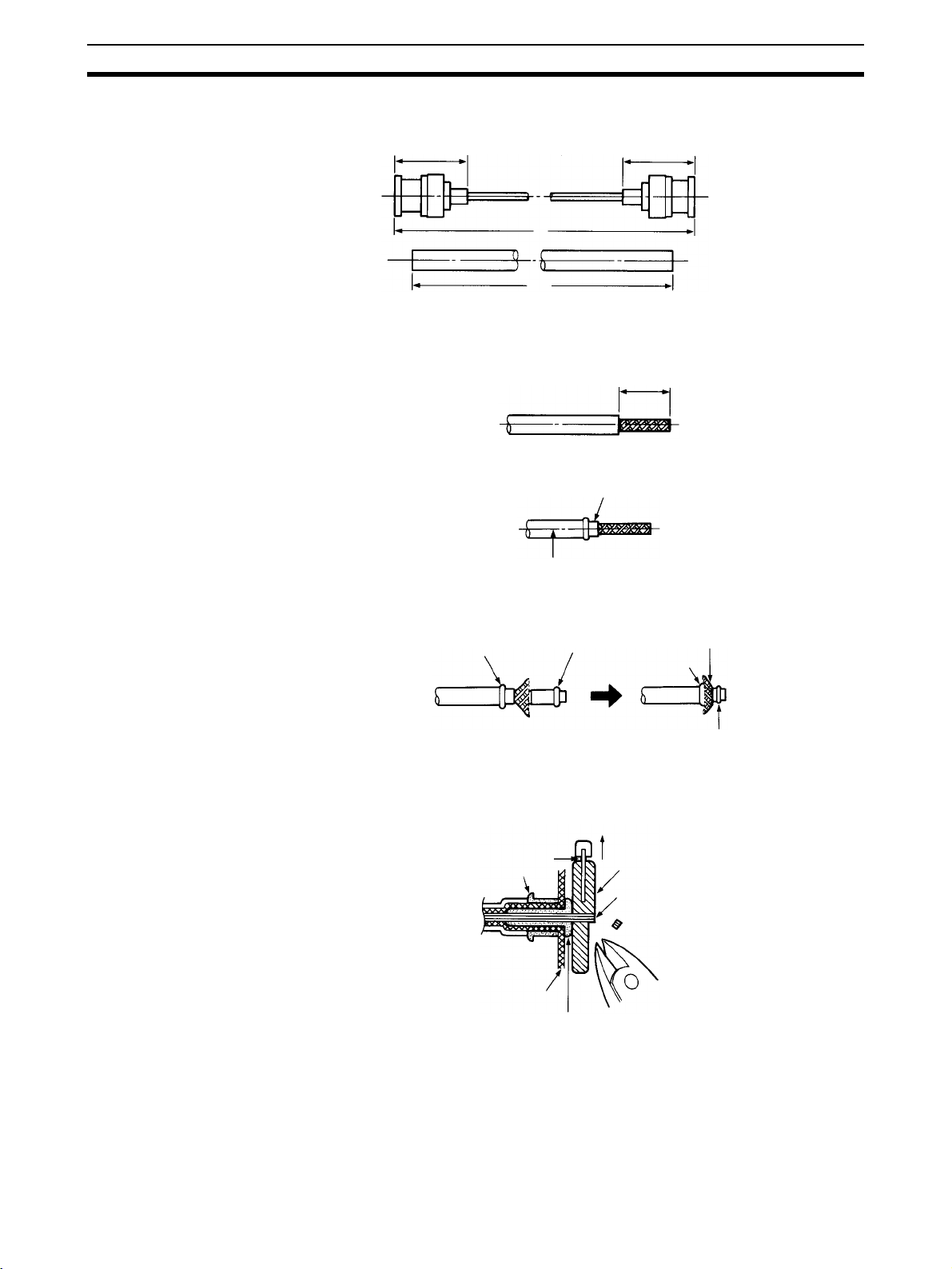
Cable Connections Section 2-4
1,2,3... 1. Cut the cable to the required length.
Approx. 24.5 mm Approx. 24.5 mm
Cable
LA mm = L mm − 12 mm
L
LA
(Unit: mm)
2. Remove 15 mm of the outer covering. Be careful not to damage or to distort the braiding.
15 mm
3. Insert the ferrule as shown below.
Ferrule
Cable
4. Spread the tip of the braiding, and insert the sleeve. Using the trimming
tool, push in the sleeve flange forcefully until it fits flush with the braiding.
Ferrule
Sleeve
Shield
Ferrule
Sleeve
5. Align A of the central conductor polyethylene projecting towards the outside of the trimming tool with the outside of the tool as shown below and
then cut the polyethylene.
B
C
Trimming tool
Conductor
A
Ferrule
Blade
Shield
Sleeve
22
Page 40

Cable Connections Section 2-4
6. Using your fingertips, press down on B on the trimming tool blade, forcing
the blade into the polyethylene, and twist several times. Continuing to
press down on B, withdraw in the direction of arrow D as shown below.
B
D
Conductor
7. Use scissors to cut off any protruding braiding as shown below.
8. Insert the contact into the contact crimp adapter, and set them inside the
crimp tool die. Insert the cable central conductor into the contact hole until
the severed face of the polyethylene meets the contact guard. Firmly grasp
the crimp tool handle and crimp.
9. Insert the completed contact subassembly into the body. Gently rotate and
press until the contact wings enter the insulator cavity, and align the contact tip with the insulator tip. After inserting the contact wings into the cavity, rotate the cable and the body until the body is crimped.
Contact
subassembly
Body
Insulator
23
Page 41

Cable Connections Section 2-4
10. Open the crimp tool handle, hold the tip of the body to the body stopper as
shown below, and close the handle until the ratchet can no longer turn.
Align the body hole with the hexagonal part of the die and crimp. A correct
crimp should resemble the diagram below.
Checks After Attaching
the Connector to the
Coaxial Cable
Body stopper
Cable
Crimp height
Body
Check that the body crimp is correct. If you crimp without holding the tip of the
body to the body stopper, the crimp will be partway along the body as shown
in the diagram on the right.
OK
Wrong
Check that the contact tip is in the same position as the open mouth of the
connector.
Body
Using a tester, check the following:
• Are the central conductor and the braiding insulated in the plug shell on
the coaxial cable connector?
• Are the plug shells conducting through the connectors at both ends of the
coaxial cable?
• Are the central conductors conducting through the connectors at both
ends of the coaxial cable?
24
Page 42
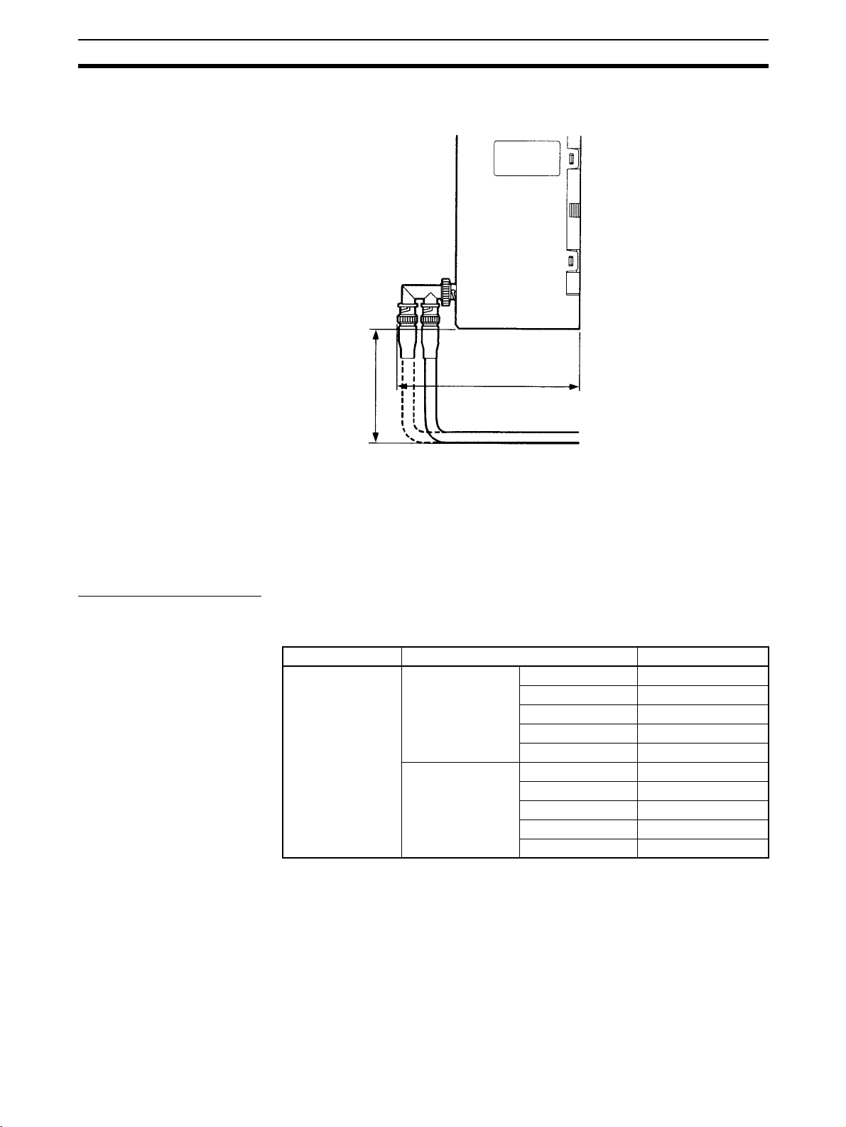
Cable Connections Section 2-4
Provide a space between the bottom of the Unit and the cable as shown
below to ensure a suitable bend radius.
200
137
(Unit: mm)
Note Separate the coaxial cable from other power lines and high-voltage lines to
prevent noise.
2-4-2 Optical Units
The following devices are required for the Optical SYSMAC LINK Network.
Required Components
Optical Fiber Cables Use the following adhesive-polished Optical Fiber Cables (Hard Plastic-clad
Fiber: H-PCF).
Name Specifications Model
H-PCF cables Black 10 m S3200-HCCB101
50 m S3200-HCCB501
100 m S3200-HCCB102
500 m S3200-HCCB502
1,000 m S3200-HCCB103
Orange 10 m S3200-HCCO101
50 m S3200-HCCO501
100 m S3200-HCCO102
500 m S3200-HCCO502
1,000 m S3200-HCCO103
25
Page 43

Cable Connections Section 2-4
Note The Optical Fiber Cable model numbers are as follows:
Connectors
S3200-H
Name Model Specifications
Connector S3200-COCF2071
Inline Adapter S3200-COIAT2000 Use to connect or extend cables.
(((((((
(See note 1.)
S3200-COCF2571
(See note 1.)
Tensioner option
None: Standard (with tension member)
N: Without tension member
Cable length
(((
A B
(A/10) x 10
Cable color
B: Black
O: Orange
Cable specification
L: With power supply line
C: Without power supply line
Type
B: Cord
C: Cable
Use to connect a cable to a node.
(Full-lock connector for crimp-cut cable.)
Use to connect a cable to a node.
(Half-lock connector for crimp-cut cable.)
(Use one adapter for each connection.)
B
m
Note (1) Production of S3200-COCF2011 (full-lock) and S3200-COCF2511 (half-
Optical Fiber Cable with
Connectors
lock) Connectors has been stopped. Use the above Connectors as replacements.
(2) Either full-lock or half-lock connectors can be used in a SYSMAC LINK
Network, but we recommend full-lock connectors to prevent accidental
disconnections during operation.
(3) The maximum distance between nodes is slightly shorter for connectors
with crimp-cut cables compared to connectors assembled with adhesive.
Also, the maximum distance is reduced due to extension loss when Inline
Adapters are used to extend cables.
The following adhesive-polished Optical Fiber Cables are available with Connectors already attached.
Specifications Length Model
Optical Fiber Cable Connectors:
S3200-COCF2011
ß
S3200-COCF2011
2 m S3200-CN201-20-20
5 m S3200-CN501-20-20
10 m S3200-CN102-20-20
15 m S3200-CN152-20-20
20 m S3200-CN202-20-20
Over 20 m S3200-CN-20-20
(Specify length (m) when ordering.)
26
Page 44

Cable Connections Section 2-4
Specifications Length Model
Optical Fiber Cable Connectors:
S3200-COCF2011
ß
S3200-COCF2511
Optical Fiber Cable Connectors:
S3200-COCF2511
ß
S3200-COCF2511
Note (1) The cables listed above are black and have power supply lines and ten-
sion members, although the power supply lines aren’t used in the SYSMAC LINK Network.
(2) All of the cables listed above are attached to the connectors with adhe-
sive.
(3) Special training is required to assemble Optical Fiber Cables and connec-
tors with adhesive.
2 m S3200-CN201-20-25
5 m S3200-CN501-20-25
10 m S3200-CN102-20-25
15 m S3200-CN152-20-25
20 m S3200-CN202-20-25
Over 20 m S3200-CN-20-25
(Specify length (m) when ordering.)
2 m S3200-CN201-25-25
5 m S3200-CN501-25-25
10 m S3200-CN102-25-25
15 m S3200-CN152-25-25
20 m S3200-CN202-25-25
Over 20 m S3200-CN-25-25
(Specify length (m) when ordering.)
Optical Fiber Cable
Use the following accessories to assemble and test Optical Fiber Cables.
Accessories
Optical Fiber
Assembly Tool
Optical Power Tester S3200-CAT2700 With S3200-CAT2702 Head Unit and
Master Fiber Set S3200-CAT2001H One meter cable for use with the
Note Use the CAK-0057 (made by Sumitomo Electric Industries, Ltd.) to assemble
the S3200-COCF2071/2571 Connectors. (Production of the S3200-CAK1062
Assembly Tool has been stopped.) The S3200-COCF2071/2571 Connectors
can be assembled using the S3200-CAK1062 by adding the JRFK-57PLUS
(made by Sumitomo Electric Industries, Ltd.).
This manual does not provide details on Optical Fiber Cable preparation. For
details, refer to the instructions provided with the CAK-0057 or S3200CAK1062 Assembly Tool.
Optical Fiber Cable Connections
All of the nodes in an Optical SYSMAC LINK Network are connected in a line
(daisy-chain configuration) with H-PCF Optical Fiber Cable.
The nodes can be connected in any order, but be sure to begin with the upper
connector (SL1) of the highest node in the network and connect to the lower
connector (SL2) in the next lower node, as shown in the following diagram.
Name Model Specifications
CAK-0057
(See note.)
Crimp-cut tool for the
S3200-COCF2071/2571 Connectors
adapter for the S3200-COCF2071/
2571 and S3200-COCF2011/2511
Connectors
S3200-CAT2702 Head Unit
27
Page 45
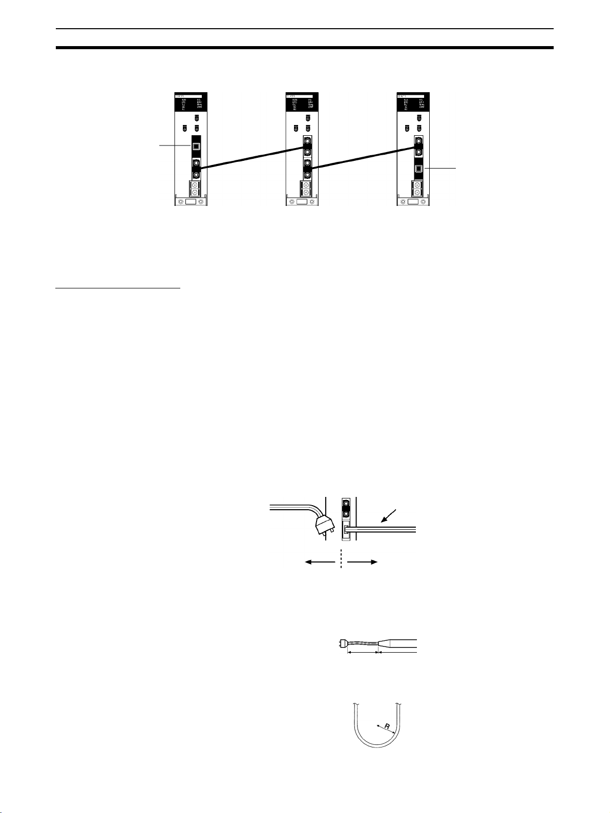
Cable Connections Section 2-4
Also be sure to cover the unused connectors on the highest and lowest nodes
in the network with the provided Optical Connector Covers.
Optical Connector Cover
(Included)
Optical Connector Cover
(Included)
← Higher Lower →
Note (1) Always use the specified Optical Fiber Cables.
(2) The maximum distance between nodes depends on the method used to
attach the connector to the cable.
Installing Connectors
A special connector is used to connect the Optical Fiber Cable to the SYSMAC LINK Unit.
This manual does not provide details on Optical Fiber Cable preparation.
Observe the following precautions when connecting the Optical Fiber Cables.
• Always turn OFF the PLC power supply before connecting Optical Fiber
Cables.
• Special tools are required to attach Optical Fiber Cables to the connectors. The cable may disconnect from the connector if the proper tools and
methods are not used during cable assembly.
• Insert the connectors completely and always check that the connectors
are locked before starting operation.
• If a connector becomes disconnected, the node will be unable to communicate with other nodes in that part of the network. The network will be
divided into two and communications with the remaining nodes will be
unreliable. Be sure not to remove connectors during communications.
Transmission possible
but unstable.
28
Isolated
(Transmission not possible)
• Do not pull on the Optical Fiber Cable too forcefully.
The maximum tension that can be applied to the cord is 10 kg and the
maximum tension that can be applied to the cable is 50 kg.
Cord
Cable
• Do not bend the cable too sharply. The minimum radius for bends is
10 cm.
Page 46
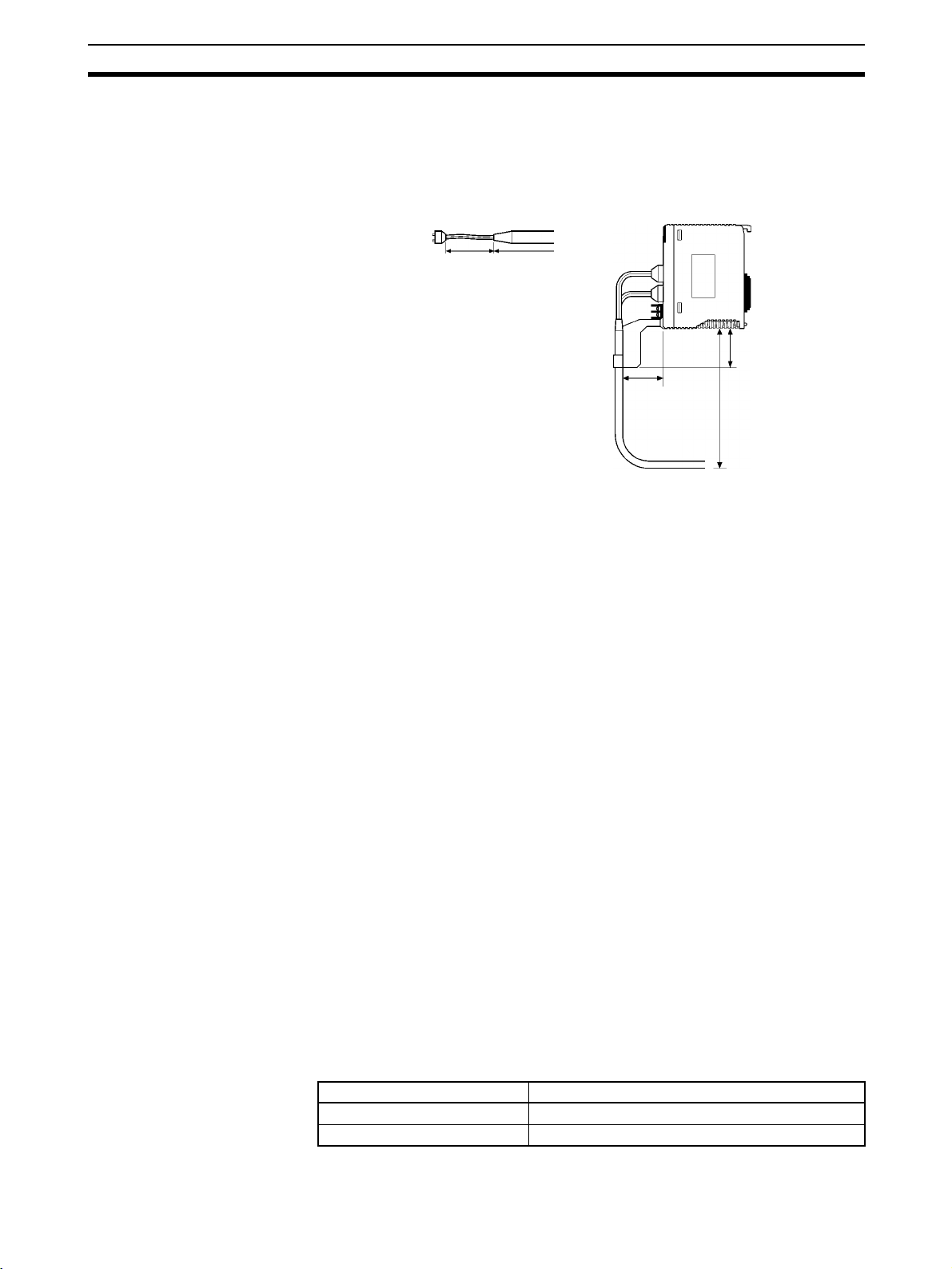
Cable Connections Section 2-4
• To prevent the Optical Fiber Cable from being pulled too forcefully, always
use the cable securing bracket and provide space behind the Unit as
shown in the following diagram. Do not exceed the maximum tension for
the cord and cable:
Cord: 0 kg (Do not apply any tension.)
Cable: 5 kg
Cord Cable
60
50
200
• Do not place objects on top of the Optical Fiber Cable. The maximum
pressure that can be placed on the cord and cable is as follows:
Cord: 30 kg/10 cm
Cable: 50 kg/10 cm
• Inspect the connector before installing it.
Connection Procedure Use the following procedure to connect Optical Fiber Cables to a Unit.
1,2,3... 1. Tighten screws in the mounting brackets so that the through-holes on the
terminal are on the top and bottom and then affix hexagonal nuts from the
opposite side of the terminal.
2. Insert bushing to the mounting bracket and secure the Unit with screws.
3. Pass the tension member through the through-holes, and tighten the terminal screws to affix the tension member.
4. Affix the cable to the mounting bracket so that it is clamped by the bracket.
Two cables can be attached at the same time.
5. Move the cable connector so that the loose ends are on the left-hand side,
and insert the Unit’s optical connector as far as it will reach.
2-4-3 Backup Power Supply
Each node requires a backup power supply for the node bypass function. Several nodes can be connected to a single power supply or each node can be
connected to an independent power supply.
Be sure that the backup power supply is providing sufficient current and voltage at the Unit’s connector.
Backup Power Supply
Specifications
The following table shows the input specifications required for backup power
supply to SYSMAC LINK Units. Be sure that the backup power supply being
used meets these specifications. (We recommend the OMRON S82K-series
Power Supplies.)
Voltage 24 V DC
Allowed voltage fluctuation 20.4 to 26.4 V DC (24 V DC –15% to +10%)
Item Specification
29
Page 47
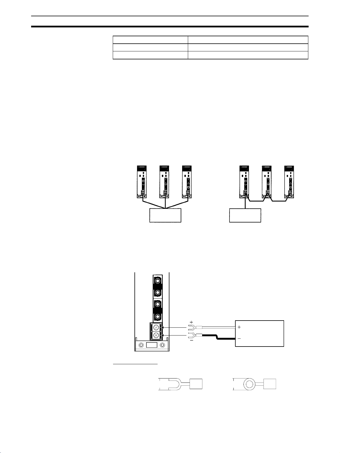
Cable Connections Section 2-4
Item Specification
Current consumption 200 mA max. at 24 V DC (per node)
Inrush current 2.5 A max. (24 V DC, 5-ms rise time)
Note (1) A label has been placed over the upper surface of the SYSMAC LINK Unit
to prevent wire cuttings from entering the Unit. When wiring the backup
power supply, leave the label in place.
(2) When wiring is complete, remove the label to avoid overheating.
(3) Use a power supply that is not connected to PLC operation, as in the case
of the node bypass function, for the backup power supply so that when
the power to the PLC is turned OFF, the backup power supply will contin-
ue.
(4) Use a dedicated power supply for the backup power supply. Do not share
a power supply being used for I/O, motors, or control systems.
(5) When two or more nodes are connected to a single backup power supply,
wire each node separately.
OK
Backup power
supply
Wrong
Backup power
supply
Note Unlike the CV500-SLK11, the CS1W-SLK11 does not require an Auxiliary
Power Supply Unit for the node bypass function. Instead, directly connect a
24-VDC external power source as a backup power supply.
Attach crimp terminals to the power supply cable when connecting the backup
power supply to the SYSMAC LINK Unit.
30
Crimp Terminals
Use an M3 crimp terminal, as illustrated below.
6.2 mm max. 6.2 mm max.
24 VDC
Backup
power
supply
Page 48

Cable Connections Section 2-4
Recommended Crimp Terminals
Manufacturer Model Remarks Suitable wiring
Japan Crimp Terminals KK
MOLEX JAPAN
CO., LTD.
V1.25-N3A Vinyl insulated
forked terminal
V1.25-MS3 Vinyl insulated
round terminal
VSY1.25-3.5L Vinyl insulated
forked terminal
RAV1.25-M3 Vinyl insulated
round terminal
Note (1) Always turn OFF the power to the PLC and the backup power supply be-
fore connecting the backup power supply cables.
(2) Separate the backup power supply wires from other power lines and high-
voltage lines to prevent noise.
(3) Always use a crimp terminal for wiring. Do not connect a wire that has
only been twisted directly to a terminal block.
(4) In the interests of safety, it is recommended that round crimp terminals
are used.
(5) When mounting the crimp terminal, always use the appropriate tools for
each crimp terminal and follow the appropriate installation procedures.
Contact the crimp terminal manufacturer for details on the appropriate
tools and procedures. Failure to use the appropriate tools and procedures
could cause cables to break.
(6) Measure the length of peeled cable during installation according to the
crimp terminal used and make sure that the peeled length is not too long.
Cover the compressed section of the crimp terminal and cable with vinyl
tape or heat-shrinking tube.
(7) Be sure not to reverse the power supply polarity.
(8) Tighten the screws on the terminal block firmly. The correct tightening
torque is 0.5 N
• m. If the screws are too loose, short-circuit, malfunction
or burning may result.
(9) Do not pull backup power supply cables with excessive force.
(10) Do not bend backup power supply cables.
(11) Do not place any object on top of backup power supply cables.
(12) Supply power only after checking the wiring thoroughly.
range
0.25 to 1.65 mm
(AWG #22 to #16)
2
0.3 to 1.65 mm
(AWG #22 to #15)
2
31
Page 49

Page 50

SECTION 3
Basic Communications
A description of the token bus method of communications used in SYSMAC LINK Systems is described briefly in this
section, as well as the basic settings necessary for operation.
3-1 SYSMAC LINK System Communications . . . . . . . . . . . . . . . . . . . . . . . . . . 34
3-2 Unit Number. . . . . . . . . . . . . . . . . . . . . . . . . . . . . . . . . . . . . . . . . . . . . . . . . . 35
3-3 Setting Node Address. . . . . . . . . . . . . . . . . . . . . . . . . . . . . . . . . . . . . . . . . . . 35
3-4 Network Address Setting . . . . . . . . . . . . . . . . . . . . . . . . . . . . . . . . . . . . . . . . 36
3-5 Network Parameters . . . . . . . . . . . . . . . . . . . . . . . . . . . . . . . . . . . . . . . . . . . . 36
3-6 Memory Areas . . . . . . . . . . . . . . . . . . . . . . . . . . . . . . . . . . . . . . . . . . . . . . . . 38
3-6-1 Word Allocations . . . . . . . . . . . . . . . . . . . . . . . . . . . . . . . . . . . . . . . 38
3-6-2 Word Applications . . . . . . . . . . . . . . . . . . . . . . . . . . . . . . . . . . . . . . 39
33
Page 51

SYSMAC LINK System Communications Section 3-1
3-1 SYSMAC LINK System Communications
SYSMAC LINK Units communicate through the SYSMAC LINK Network, a
token bus LAN. This section describes the token bus communications used in
the SYSMAC LINK Network.
Token Bus
Communications
In token bus communications, individual nodes are connected to a main trunk
line as a common bus line, as shown in the figure below.
To avoid having two nodes attempt to transmit simultaneously, only one node
has the right to transmit at a time. The right to transmit is held by the node that
holds what is called the token, which is passed in sequence from node to
node, beginning with the node with the lowest node address (the polling node,
see below).
If the token is passed to a node that does not have data to transmit, the token
is immediately passed to the node with the next higher node address. The
node with the highest node address passes the token back to the node with
the lowest node address. In this way, each node in the network has its turn to
transmit data without interfering with other nodes.
Lowest node address
NodeNodeNodeNode
Connecting cable
(trunk line)
NodeNode Node
Highest node address
Control
sequence
Polling Node In a SYSMAC LINK Network there is one node, called the polling node, that
controls communications in the network. Normally, the Unit with the lowest
node address is the polling node. If the polling node fails, the node with the
next higher node address automatically becomes the polling node, preventing
the whole network from failing.
Startup Node The node that starts the data link in a SYSMAC LINK Network is called the
startup node. The data link operates using the parameter settings in the DM
Area at the startup node. With automatic allocation of link words, the DM
parameter area settings are used, and with manual allocation, the common
link parameters in the startup node are used.
Communications Cycle The token in a SYSMAC LINK Network is first passed from the polling node.
The token is passed in sequence from node to node by node address until it is
finally returned to the polling node. One complete circuit around the network is
known as a token cycle.
At the end of each token cycle, the polling node polls all of the nodes in the
network to check whether any nodes have been added to or removed from the
network. The updated information on the network is transmitted to all nodes.
This polling and updating process is known as the polling cycle.
When the control cycle is completed, the polling node once again passes the
token, beginning the next token cycle. Together the token cycle and control
34
Page 52

Unit Number Section 3-2
cycle make up the communications cycle, and the time required for the communications cycle is known as the communications cycle time.
Communications cycle
Token cycle Polling cycle
Network Parameters The communications cycle time is one of the network parameters. The other
network parameters are the number of polled units, maximum number of
frames, and the maximum node address. These parameters are transmitted
from the polling node to the other nodes in the network. Refer to 3-5 Network
Parameters for details on the network parameters.
Refresh Cycle Time Data is constantly being refreshed in the data link words between the SYS-
MAC LINK Unit and the CPU Unit while the data links are operating. By
refreshing data, the CPU Unit sends local node data to the SYSMAC LINK
Unit, and receives data from other nodes from the SYSMAC LINK Unit. The
interval between data refreshing is called the refresh cycle time. The refresh
cycle time can be monitored using the Support Software.
Communications cycle
Token cycle Polling cycle
3-2 Unit Number
Up to four SYSMAC LINK Units can be mounted on a CS-series PLC and
used to connect each Unit to a different SYSMAC LINK Network. Because the
PLC incorporates bridge and gateway functions, these and other networks
can exchange data via the CPU Unit. If more than one SYSMAC LINK Unit or
other CPU Bus Unit is mounted on a single PLC, however, each Unit needs a
unit number for identification.
Setting Use the rotary switches on the front panel to set the unit number.
Unit No. 6 Unit No. 12 (hexadecimal C)
Setting Value Range A total of 16 SYSMAC LINK Units and/or other CPU Bus Units can be
mounted on a single PLC. Of these, up to four can be SYSMAC LINK Units.
The unit number settings range is from 0 to F Hex.
Note (1) Each Unit connected to the same PLC must have a unique number.
(2) Turn OFF the PLC when setting the rotary switches.
(3) If the unit number of any node has been changed, the I/O table on the
PLC must be generated again and that node must be turned ON after all
other nodes have been turned ON.
3-3 Setting Node Address
In token bus communications used in the SYSMAC LINK Network, the node
addresses make a logical ring around which the token is passed. The logical
ring of node addresses takes the place of the actual physical ring used in
some other networks. Consequently, proper setting of the node addresses is
essential to network operation.
35
Page 53

Network Address Setting Section 3-4
Settings Node address switches determine the node address. The left switch sets the
ten’s digit; the right switch sets the one’s digit. The node address must be
between 01 and 62. Each SYSMAC LINK Unit in a Network must have a
unique node address.
Node number: 53
Note (1) Always turn OFF the PLC power before setting or changing node ad-
dress.
(2) If the node address set on the Unit is outside of the allowed range (01 to
62), a communications error will occur and the red ERC indicator will light
on the Unit.
(3) Each Unit in the network must have a unique node address, so be sure
not to use the same address on more than one Unit.
(4) The token is passed from node to node according to node addresses, so
the more dispersed the node addresses are, the greater distance the token has to travel. In optical fiber systems, the communications cycle time
depends on the distance the token has to travel, so set node addresses
in the same order as the nodes’ positions in the network if possible.
(5) If you change a node address, start up the changed node last, and have
it participate in the network last.
Node number: 7
3-4 Network Address Setting
It is necessary to set a network address on each PLC for data exchange
between networks. By setting the network address, the local node can
exchange data with a destination node even if there is another network
between them.
Setting Use the Support Software to set the network address in the routing tables in
the CPU Unit (refer to 5-2 Routing Tables). Refer to the Support Software
operation manuals for setting details.
Setting Range A system can include up to 127 networks. The setting range of the network
address is thus 1 to 127 (decimal). (Network address 0 is used to indicate the
local network.)
3-5 Network Parameters
The operation of the SYSMAC LINK Network is determined by the network
parameters. Network parameters are set with Peripheral Devices, such as the
Support Software, and are automatically backed up within the SYSMAC LINK
Unit. The network parameters stored in the polling node are used in actual
system operation; the network parameters in other Units are ignored.
Network Parameters The following table shows the network parameters, their default values, and
the ranges within which the parameters can be set by the user. Default values
and setting ranges are in decimal.
Network parameter Default value Setting range
Communications cycle time Automatic 5 to 255
Maximum node address 62 2 to 62
36
Page 54

Network Parameters Section 3-5
Network parameter Default value Setting range
Number of polled units per communications cycle
Maximum number of frames per
communications cycle
Communications Cycle Time
This parameter sets a timer that fixes the length of the communications cycle
to the specified time. The timer operates only when the data link is in operation. Set the communications cycle time when setting the data link table’s
common link parameters.
When the timer is in operation, the communications cycle time is fixed at the
specified value, independent of the number of events that occur. Refer to 4-11
Data Link Characteristics for the formula needed to calculate the communications cycle time when the data link is set for automatic generation.
Maximum Node Address
This parameter sets the maximum node address that a node can have and
still be a part of the network. Nodes with node addresses greater than the
maximum node address will not be polled, and therefore will not participate in
network communications. This eliminates unnecessary polling of units with
node addresses above the maximum, and thus reduces the time required for
communications.
4 1 to 62
10 5 to 255
Setting Network
Parameters
Note Set the maximum node address above the highest node address set on the
SYSMAC LINK Units currently connected unless you specifically want to
exclude one or more nodes from system operation.
Number of Polled Nodes
This parameter determines how many nodes will be polled by the polling node
during a polling cycle. Setting a high number of Units increases the communications cycle time, but reduces the time required to recognize that nodes have
been removed from or added to the network.
Maximum Number of Frames
This parameter determines how many event transmissions can take place
during a token cycle when data links are operating. With the default value of
10 frames, up to 4 event transmissions can be issued.
Event transmissions include instructions such as SEND(90), RECV(98), or
CMND(490), as well as processes such as remote monitoring and remote
programming from the Support Software.
Setting a high number of frames increases the communications cycle time,
while setting a low number will cause errors because of restrictions on event
transmissions when the data link is operating. Increase the number of frames
by three for each additional event transmission if data links are operating.
Network parameters are set from the Support Software. Refer to the Support
Software manual for details. Network parameters are enabled immediately
after being set.
Note (1) Do not set network parameters while data links are operating.
(2) Set the maximum node address to a value greater than the maximum
node address used in the SYSMAC LINK Units connected to the network.
37
Page 55
Memory Areas Section 3-6
3-6 Memory Areas
The CPU Bus Unit Area and part of the DM Area in the CPU Unit are used to
write or read the status of the nodes and the data links of SYSMAC LINK
Units. The data from the SYSMAC LINK Unit is written to the input words in
these areas.
3-6-1 Word Allocations
The memory areas that are used to write or read the data will be allocated
according to the unit number.
CPU Bus Unit Area Each CPU Bus Unit is allocated 25 words from between CIO 1500 and
CIO 1899 as follows:
Unit No. Words Unit No. Words
0 CIO 1500 to CIO 1524 8 CIO 1700 to CIO 1724
1 CIO 1525 to CIO 1549 9 CIO 1725 to CIO 1749
2 CIO 1550 to CIO 1574 10 CIO 1750 to CIO 1774
3 CIO 1575 to CIO 1599 11 CIO 1775 to CIO 1799
4 CIO 1600 to CIO 1624 12 CIO 1800 to CIO 1824
5 CIO 1625 to CIO 1649 13 CIO 1825 to CIO 1849
6 CIO 1650 to CIO 1674 14 CIO 1850 to CIO 1874
7 CIO 1675 to CIO 1699 15 CIO 1875 to CIO 1899
DM Area Each CPU Bus Unit is also allocated 100 words from between D30000 and
D31599 as follows:
Unit No. Words Unit No. Words
0 D30000 to D30099 8 D30800 to D30899
1 D30100 to D30199 9 D30900 to D30999
2 D30200 to D30299 10 D31000 to D31099
3 D30300 to D30399 11 D31100 to D31199
4 D30400 to D30499 12 D31200 to D31299
5 D30500 to D30599 13 D31300 to D31399
6 D30600 to D30699 14 D31400 to D31499
7 D30700 to D30799 15 D31500 to D31599
38
Page 56

Memory Areas Section 3-6
3-6-2 Word Applications
The applications of the words in the CPU Bus Link Area and DM Area that are
allocated to SYSMAC LINK Units are described in the following tables.
CPU Bus Unit Area The words allocated in the CPU Bus Unit Area to a SYSMAC LINK Unit are
used to access the status of the SYSMAC LINK System as shown in the following table.
I/O Word Bit Item Page
--- +0 0 to 15 Reserved by the system. --Inputs
(from SYS-
MAC LINK
Unit to CPU
Unit)
+1 0 1: Network parameter error 129
1 1: Data link table error 129
2 1: Routing table error 129
3 1: Communications Unit (SYSMAC LINK Unit) setting error --4 to 6 Reserved by the system. --7 1: EEPROM error --8 1: Node address setting error 128
9 1: Node address duplication error 128
10 1: Network parameter disagreement error --11 1: Network controller error
12 to 14 Reserved by the system. --15 0: No error log record
+2 to +4 0 to 15 Network participation (1 bit per Unit for each of 62 Units)
+5 0 to 13
14 to 15 Reserved by the system. ---
+6 0 to 7 Local node address 35
8 to 15 Local network address 36
+7 0 to 7 Node address of polling node 34
8 to 15 Local unit number 35
+8 to +22 0 to 15 Data link status on each node using 4 bits per Unit for each of 62 Units:
+23 0 to 7
8 to 13 Node address of startup node (for data links)
15 Local Data Link Active Flag
+24 0 to 10 Reserved by the system. ---
11 0: No power supply
12 to 15 Reserved by the system. ---
1: Error log record(s) exists
0: Not participating
1: Participating
CPU Unit operating, CPU Unit error, communications error, no error
(data links operating)
1: Local node data links active.
0: Local node data links not active.
1: Power being supplied (CS1W-SLK11 only)
128
40
56
17
39
Page 57

Memory Areas Section 3-6
Network Participation Status
If a node is participating in a network, the bit corresponding to the node
address will be ON. Node addresses (1 through 62) and their corresponding
bits are listed in the following table. (Bits 14 and 15 of word +5 are always 0.)
Word: 1500 + (25 x Unit Number) + 2 to 5
12 11 10 9 876543210
Word
15 14 13
Bit
+2
16
15 14 13 12 11 10 9 8 7 6 5 4 3 2 1
32+3 31 30 29 28 27 26 25 24 23 22 21 20 19 18 17
48+4 47 46 45 44 43 42 41 40 39 38 37 36 35 34 33
-+5 - 6261605958575655545352515049
Note Even if the local node is disconnected from the network, only the bit corre-
sponding to the local node is turned OFF (i.e., the entire status area participating in the network is not turned OFF). While the local node is
disconnected, the bits corresponding to the other nodes will not be refreshed,
even if the participation status of other nodes changes.
Software Switches (D30000 + 100
CPU Bus Unit Settings Initialization (See note)
0: Do not initialize CPU Bus Unit Settings
1: Initialize CPU Bus Unit Settings
Polling Node/Polled Node Bit
0: Polling node
1: Polled node
Note Initializes the network parameters registered in the CPU Bus Unit Setting Area in the CPU Unit and
clears the data link tables.
× Unit Number)
Data link Star t Bit
Start: Changed from OFF to ON or already ON when power is turned ON
Stop: Changed from ON to OFF
Data Link Mode
00: Manual
01: Automatic for CIO Area only
10: Automatic for DM Area only
11: Automatic for CIO and DM Areas
Number of Send Words per Node
CIO Area DM Area
00: 4 words
01: 8 words
10: 16 words
11: 32 words
8 words
16 words
32 words
64 words
40
Page 58

SECTION 4
Data Links
The operation of data links, procedures required to establish data links, and methods of monitoring data link operations
are described in this section.
4-1 Introduction . . . . . . . . . . . . . . . . . . . . . . . . . . . . . . . . . . . . . . . . . . . . . . . . . . 42
4-2 Data Link Specifications . . . . . . . . . . . . . . . . . . . . . . . . . . . . . . . . . . . . . . . . 43
4-3 Data Link Indicators. . . . . . . . . . . . . . . . . . . . . . . . . . . . . . . . . . . . . . . . . . . . 44
4-4 Data Link Settings . . . . . . . . . . . . . . . . . . . . . . . . . . . . . . . . . . . . . . . . . . . . . 44
4-4-1 Rotary Switches . . . . . . . . . . . . . . . . . . . . . . . . . . . . . . . . . . . . . . . . 44
4-4-2 Specifying Data Link Mode and Number of Data Link Words . . . . 45
4-4-3 Data Link Start/Stop Bit. . . . . . . . . . . . . . . . . . . . . . . . . . . . . . . . . . 45
4-5 Creating Data Links . . . . . . . . . . . . . . . . . . . . . . . . . . . . . . . . . . . . . . . . . . . . 46
4-5-1 Automatic and Manual Settings. . . . . . . . . . . . . . . . . . . . . . . . . . . . 46
4-5-2 Automatic Data Link Tables . . . . . . . . . . . . . . . . . . . . . . . . . . . . . . 47
4-5-3 Manually Generating Data Link Tables . . . . . . . . . . . . . . . . . . . . . . 48
4-5-4 Table Backup . . . . . . . . . . . . . . . . . . . . . . . . . . . . . . . . . . . . . . . . . . 48
4-6 Data Link Area Allocations . . . . . . . . . . . . . . . . . . . . . . . . . . . . . . . . . . . . . . 49
4-6-1 Automatic Settings . . . . . . . . . . . . . . . . . . . . . . . . . . . . . . . . . . . . . . 49
4-6-2 Manual Settings . . . . . . . . . . . . . . . . . . . . . . . . . . . . . . . . . . . . . . . . 49
4-6-3 Refreshing Data Links with Automatic Settings . . . . . . . . . . . . . . . 51
4-6-4 Refreshing Data Links with Manual Settings . . . . . . . . . . . . . . . . . 52
4-7 Data Link Table Example. . . . . . . . . . . . . . . . . . . . . . . . . . . . . . . . . . . . . . . . 53
4-8 Controlling Data Links. . . . . . . . . . . . . . . . . . . . . . . . . . . . . . . . . . . . . . . . . . 55
4-8-1 DM Parameter Area Software Switches . . . . . . . . . . . . . . . . . . . . . 56
4-8-2 DATA LINK START/HALT Commands . . . . . . . . . . . . . . . . . . . . . 56
4-8-3 CX-Net in CX-Programmer . . . . . . . . . . . . . . . . . . . . . . . . . . . . . . . 56
4-9 Data Link Status . . . . . . . . . . . . . . . . . . . . . . . . . . . . . . . . . . . . . . . . . . . . . . . 56
4-9-1 Data Link Status. . . . . . . . . . . . . . . . . . . . . . . . . . . . . . . . . . . . . . . . 57
4-9-2 Word Structure . . . . . . . . . . . . . . . . . . . . . . . . . . . . . . . . . . . . . . . . . 59
4-10 Data Link Precautions . . . . . . . . . . . . . . . . . . . . . . . . . . . . . . . . . . . . . . . . . . 60
4-11 Data Link Characteristics . . . . . . . . . . . . . . . . . . . . . . . . . . . . . . . . . . . . . . . . 62
4-11-1 Data Link Communications Cycle Time . . . . . . . . . . . . . . . . . . . . . 62
4-11-2 Data Exchange Timing. . . . . . . . . . . . . . . . . . . . . . . . . . . . . . . . . . . 64
4-11-3 Calculation Examples for Data Link I/O Response Times . . . . . . . 65
4-12 CX-Programmer Procedures . . . . . . . . . . . . . . . . . . . . . . . . . . . . . . . . . . . . . 67
4-12-1 Overall Procedure. . . . . . . . . . . . . . . . . . . . . . . . . . . . . . . . . . . . . . . 67
4-12-2 Data Link Settings . . . . . . . . . . . . . . . . . . . . . . . . . . . . . . . . . . . . . . 68
41
Page 59

Introduction Section 4-1
4-1 Introduction
Data links can be created between PLCs or PLCs and computers in a SYSMAC LINK Network to exchange data. This data is transferred between interconnected PLCs automatically without requiring the use of normal I/O Units.
Words in the CIO and/or DM Areas are set aside as the data link words in
each PLC that is in the data link. Some of the data link words are allocated to
the local node and the rest are allocated to other nodes. Data can be written
only to the words allocated to the local node. During data link refreshing, data
written in the local node is transferred to corresponding words in other nodes’
memory areas. The result is that each PLC in the data link has a common
data link area, the only difference being in the read/write permissions for the
various words in it.
Data Link Tables The data link words in each PLC are defined by a data link table, which
includes both common link parameters and refresh parameters. The common
link parameters define the words output by each node in the data link and are
thus the same for all nodes, and the refresh parameters define the words
input by each node and can thus be different for each node.
Data link tables can be generated automatically or manually. Automatic generation is accomplished simply by setting parameters in the DM Area. Manual
generation is accomplished by setting specific data links from the CX-Net in
CX-Programmer.
The following diagram shows the operation of a data link among four nodes in
a network. This data link was generated manually.
Data link words
Data link table
Node 2 Node 5 Node 6 Node 8
Link Area Link Area Link Area Link Area
1000
1010
1030
1049
Refresh parameters
(can differ from
node to node)
#2
#5
#6
1010
1020
1039
#2
#5
Refresh parameters
(can differ from
node to node)
1000
1020
1039
Refresh parameters
(can differ from
node to node)
Common link
parameters
(the same in all
nodes)
#5
#6
1005
1015
1035
1054
#2
#5
#6
Refresh parameters
(can differ from
node to node)
42
Page 60
Data Link Specifications Section 4-2
Table Generation Data link tables can be generated automatically or manually. Data link tables
generated automatically are identical in all PLCs in the data link, with the
words of the data areas listed below divided equally among 2, 4, 8, or 16
nodes. The number of words allocated to each node depend on the number of
nodes linked and is given in 4-2-1 Specifications Ta bl e later in this section.
CIO Area CIO 1000 to CIO 1063
DM Area D00000 to D00127
Manual generation provides much greater flexibility in making data links
among PLCs, but require that you manually input the data link tables. Manually generated data links can contain far more words and can use any part of
the CIO Area and/or DM Area, as shown in the following table.
Area Data Link Area
CIO Area CIO 0000 to CIO 6143
DM Area D00000 to D32767
Note Use Ver. 1.2 Service Pack 1 of the CX-Programmer. Settings for CS-series
SYSMAC LINK Units cannot be made with earlier versions of the CX-Programmer.
Controlling Data Links Data links can be activated and deactivated by turning ON and OFF bit 00 of
the first CPU Bus Link Area word allocated to the SYSMAC LINK Unit in PLC
memory, i.e., bit 00 of word D30000 + (100 x unit number).
4-2 Data Link Specifications
Basic specifications for data links are provided in the following table.
Item Description
Number of data link nodes 62 max., 2 min.
Number of linked words per node CIO Area: 254 words max.
Maximum number of linked words
in network
Automatically generated data links Set in DM Area parameters.
Manually generated data links Set from the CX-Net in CX-Programmer.
Status Area (in CPU Bus Link
Area)
Data link table backup CPU Bus Unit Setting Area inside CPU Unit
Data Link Allocations for Automatic Settings
Area Words allocated Number of words per node
CIO Area CIO 1000 to CIO 1063 32 16 8 4
DM Area D00000 to D00127 64 32 16 8
DM Area: 254 words max.
2,966 words
(918 words for any Network with one or more
C200H PLCs)
(See following table)
CIO 1500 + (unit number x 25) + 8 to 23
(See following table)
(only for manually set data links)
2 nodes 4 nodes 8 nodes 16 nodes
43
Page 61
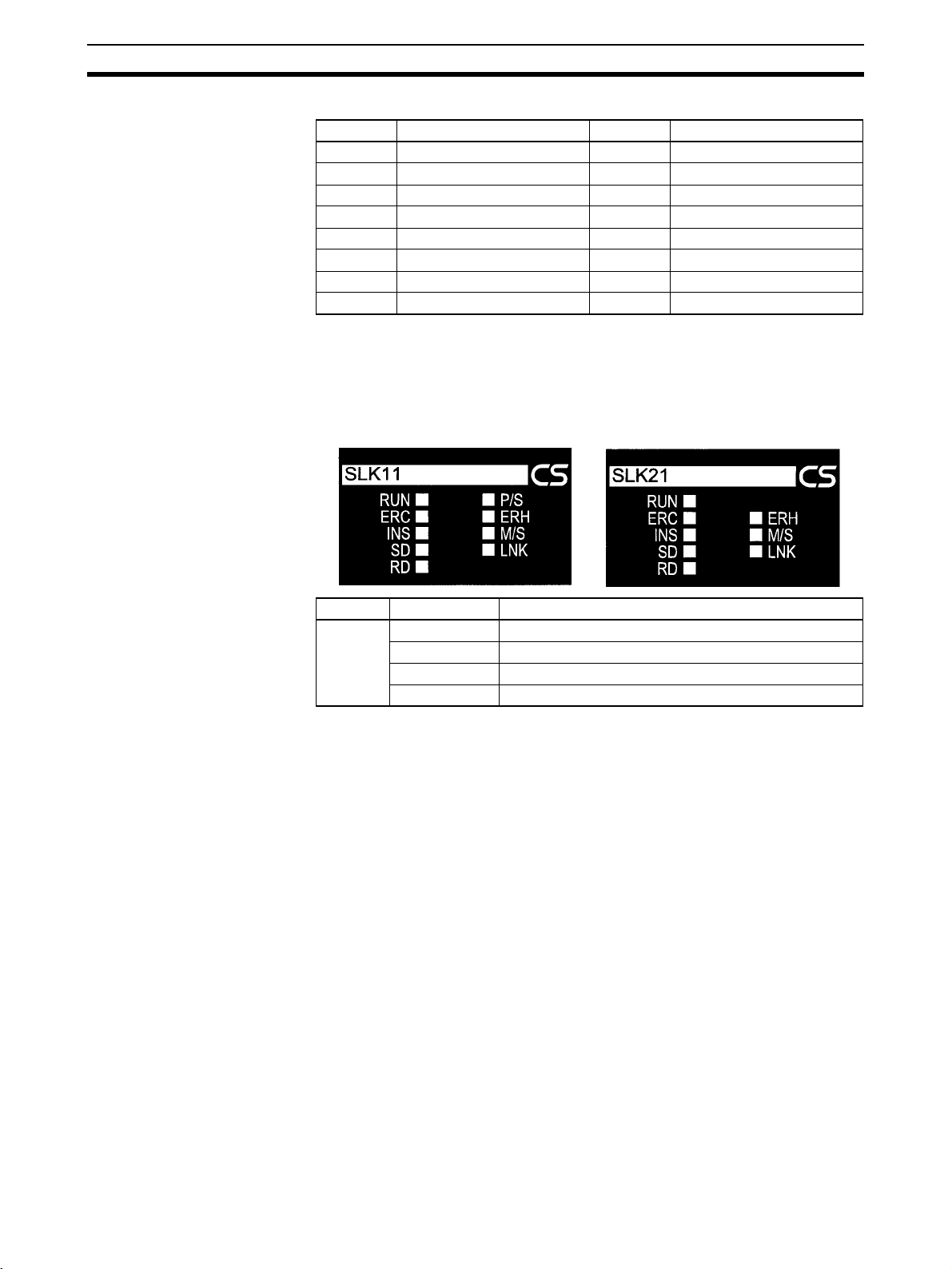
Data Link Indicators Section 4-3
Status Area Words
Unit No. Words Unit No. Words
0 CIO 1508 to CIO 1523 8 CIO 1708 to CIO 1723
1 CIO 1533 to CIO 1548 9 CIO 1733 to CIO 1748
2 CIO 1558 to CIO 1573 10 CIO 1758 to CIO 1773
3 CIO 1583 to CIO 1598 11 CIO 1783 to CIO 1798
4 CIO 1608 to CIO 1623 12 CIO 1808 to CIO 1823
5 CIO 1633 to CIO 1648 13 CIO 1833 to CIO 1848
6 CIO 1658 to CIO 1673 14 CIO 1858 to CIO 1873
7 CIO 1683 to CIO 1698 15 CIO 1883 to CIO 1898
4-3 Data Link Indicators
The data link status can be checked using an indicator on the SYSMAC LINK
Unit.
CS1W-SLK11 CS1W-SLK21
Name Condition Meaning
LNK Lit Data links are operating normally.
Note Refer to Setup and Activation in 4-10 Data Link Precautions for details.
4-4 Data Link Settings
The following settings are required to run data links.
4-4-1 Rotary Switches
Set the node address using the rotary switches on the front of the Unit. Refer
to 3-3 Setting Node Address for details on setting the rotary switches.
Flashing Data links are not active due to data link table error.
Rapid flashing Data link table communications cycle time is too short.
Not lit Data links are not active.
44
Page 62

Data Link Settings Section 4-4
4-4-2 Specifying Data Link Mode and Number of Data Link Words
Set the data link mode to either automatic settings or manual settings, and set
the number of send words per node for automatic settings. These settings are
made in the DM Parameter Area allocated to the SYSMAC LINK Unit.
Word: D30000 + (100 x Unit number)
Bit
Data Link Mode
00: Manual
01: Automatic with CIO Area only
10: Automatic with DM Area only
11: Automatic with CIO and DM Areas
Number of Words per Node (automatic settings only)
CIO Area
00: 4 words
01: 8 words
10: 16 words
11: 32 words
"---": Other settings
DM Area
8 words
16 words
32 words
64 words
Note (1) Set data link tables in each SYSMAC LINK node on the network when
specifying manual data link tables.
(2) The data link mode (manual settings or automatic settings) and the data
link system are determined by the data link settings for the startup node.
(3) Be sure to set the data link mode (manual settings) and the data link table
in the DM parameter area of the startup node when using manual set-
tings.
(4) Be sure to set the data link mode (automatic settings) and the number of
data link words in the DM parameter area of the startup node when using
automatic settings.
(5) The data links will not operate unless the settings are correct.
4-4-3 Data Link Start/Stop Bit
You can start and stop the data links by turning ON and OFF the bit in the first
word in the startup node in the DM Area allocated in the CPU Bus Unit. This
bit is in the DM Parameter Area allocated to the SYSMAC LINK Unit.
Words: D30000 + (100 x unit number)
Bit
!Caution Check the following before starting the data links. If the data link table settings
or the DM parameter settings are unsuitable, there is a risk of injury due to
unanticipated operation of the system.
"---": Other settings
Data Link Start/Stop Bit
The data links will start when the bit is turned ON
or if it is already ON when the power is turned ON.
The data links will be stopped when the bit is
turned OFF.
45
Page 63

Creating Data Links Section 4-5
a. Manual settings: Check that suitable data link tables have been set in
each data link node. Check that data link tables have been deleted for
nodes not participating in the data links.
b. Automatic settings: Check that suitable DM parameters have been set
in the data link startup node.
!Caution Even if the data link table settings or the DM parameter settings are suitable,
check that there will be no adverse effects on the controlled equipment before
starting or stopping the data links.
4-5 Creating Data Links
Data link tables store information required to run data link functions. The data
link area is created, and data is exchanged, based on the data link tables.
With manual settings, data link tables are backed up in the settings area in the
words allocated to SYSMAC LINK Unit as a CPU Bus Unit in the CPU Unit.
Note Data link areas must be continuous in the CIO Area or the DM Area. You can-
not make settings which leave unused words between the data link areas in
either the CIO Area or the DM Area.
4-5-1 Automatic and Manual Settings
• Automatic settings: Data link tables created automatically from the DM
parameter area settings.
• Manual settings: Data link tables set using Support Software.
Select either automatic or manual generation by specifying the data link mode
in the DM parameter area allocated to the SYSMAC LINK Unit in the DM
Area.
The differences between manually and automatically set data links are outlined in the following table.
Item Automatic setting Manual setting
Data link mode setting in
DM parameter area
(D30000 = 100 x unit No.)
Number of linked words All nodes have the same
Linkable words The following words are
Number of linkable nodes The number of nodes
Using CIO Area only
Bit 5: 0, bit 4: 1
Using DM Area only
Bit 5: 1, bit 4: 0
Using CIO Area and DM
Area
Bit 5: 1, bit 4: 1
number of linked words.
automatically used:
CIO 1000 to CIO 1063
D00000 to D00127
linked and the node
addresses are automatically set depending on the
number of words set per
node.
Bit 5: 0
Bit 4: 0
The number of words read
and the number of words
written can be set independently for each node.
Any of the words in the
CIO and DM Areas can be
linked.
Data links can be set for
any portion or all of the
nodes (max.: 62).
46
Page 64

Creating Data Links Section 4-5
4-5-2 Automatic Data Link Tables
Settings To automatically generate data link tables, the data link mode in the CPU Unit
DM Area parameters must be set for automatic generation and the numbers
of words per node in each of the CIO and DM Areas must be set. The data
link mode can be set to CIO Area only, DM Area only, or CIO and DM Areas.
You can select the number of send words to each node using the data link
word settings.
Allocated Words The words allocated to each node for the various word settings are given in
the following table.
DM Parameter Area (D30000 + 100 x unit number)
Automatic data link mode settings Words per node
Bit 5: 0
Bit4: 1
Bit 5: 1
Bit 4: 1
CIO Area
words*
1000 to 1003 D00000 to D00007 Node 1 Node 1 Node 1 Node 1
1004 to 1007 D00008 to D00015 Node 2
1008 to 1011 D00016 to D00023 Node 3 Node 2
1012 to 1015 D00024 to D00031 Node 4
1016 to 1019 D00032 to D00039 Node 5 Node 3 Node 2
1020 to 1023 D00040 to D00047 Node 6
1024 to 1027 D00048 to D00055 Node 7 Node 4
1028 to 1031 D00056 to D00063 Node 8
1032 to 1035 D00064 to D00071 Node 9 Node 5 Node 3 Node 2
1036 to 1039 D00072 to D00079 Node 10
1040 to 1043 D00080 to D00087 Node 11 Node 6
1044 to 1047 D00088 to D00095 Node 12
1048 to 1051 D00096 to D00103 Node 13 Node 7 Node 4
1052 to 1055 D00104 to D00111 Node 14
1056 to 1059 D00112 to D00119 Node 15 Node 8
1060 to 1063 D00120 to D00127 Node 16
Bit 5: 1
Bit 4: 0
DM Area words
(see note)
Bit 7: 0
Bit 6: 0
CIO:
4 Wds,
DM:
8 Wds
Bit 7:0
Bit 6: 1
CIO:
8 Wds,
DM:
16 Wds
Bit 7: 1
Bit 6: 0
CIO:
16 Wds,
DM:
32 Wds
Bit 7: 1
Bit 6: 1
CIO:
32 Wds,
DM:
64 Wds
Note When using a data link that combines C-series SYSMAC LINK Units, CS-
series SYSMAC LINK Units, and CVM1/CV-series SYSMAC LINK Units, LR
00 to LR 63 in C-series PLCs correspond to CIO 1000 to CIO 1063 in CS/CVseries PLCs and DM 0000 to DM 0127 correspond to D00000 to D00127.
47
Page 65

Creating Data Links Section 4-5
4-5-3 Manually Generating Data Link Tables
You can manually set the data link words by setting D30000 + 100 x unit number, bit 5 and bit 4 to OFF. The data links are set in the DM parameter area
allocated to the SYSMAC LINK Unit as a CPU Bus Unit.
The manual settings, made with the CX-Net in CX-Programmer, are as follows:
Item Contents
Common link
parameters
Refresh
parameters
Communications cycle time Set the data link communications cycle time.
Select automatic or manual setting. Manual setting range: 5 to 255 ms
Local node
send size
PLC type Select “CS” when using a CS-series SYSMAC LINK Unit.
Data link start
address
Refresh node order Set in order the node addresses with which the local node will refresh data,
CIO Area Set the CIO Area local node send size in
words. Setting range: 0 to 254 words.
DM Area Set the DM Area local node send size in
words. Setting range: 0 to 254 words.
If using CX-Programmer Ver. 1.2 Service Pack 1, set the CV/CVM1. (If the
CV/CVM1 is set, then only the ranges supported by the CVM1/CV-series
PLCs can be set.)
CIO Area Set the start address in the CIO Area data link area for the local node.
Setting range: CIO 0000 to 6143
DM Area Set the start address in the DM Area data link area for the local node.
Setting range: D00000 to D32767
starting with the data link start addresses set above.
If the address of the local node is set, it will send the specified word data to
other nodes. If the address of another node is set, the local node will receive
the data sent by that node. For example, if you enter 3, 2, 1 as the refresh
order, the node addresses will be allocated in the order 3, 2, 1, starting from
the start address. If the local node address is 1, it will receive data from
node 3, then from node 2, and finally, it will send data itself).
Always include the local node in the refresh node order. Data will not be
received from the local node by another other node if the local node is not
specified.
Note If 0 is set, the local node
will not send data (i.e., it
will receive only).
4-5-4 Table Backup
Note Data link tables are set in the CPU Bus Unit Settings Area of the CPU Unit. If
For settings using CX-Net, refer to 4-12 CX-Programmer Procedures.
When using a data link that combines C-series SYSMAC LINK Units, CS-
series SYSMAC LINK Units, and CVM1/CV-series SYSMAC LINK Units, set
the CIO Area data link words bearing in mind that the C-series data links have
a maximum of 64 words from LR0 to LR63.
The data link area must be continuous in the CIO Area and in the DM Area.
Data link tables are automatically stored up in the CPU Bus Unit Settings Area
of the CPU Unit of the SYSMAC LINK Unit involved if backup is specified from
the Support Software. It is advisable, however, for common link and refresh
parameters to be backed up for safety. Back up using the Support Software.
For details, refer to the Support Software operation manuals.
the CPU Unit is replaced or if the unit number or node address of a SYSMAC
LINK Unit is altered, it is necessary to set the data link tables again.
48
Page 66
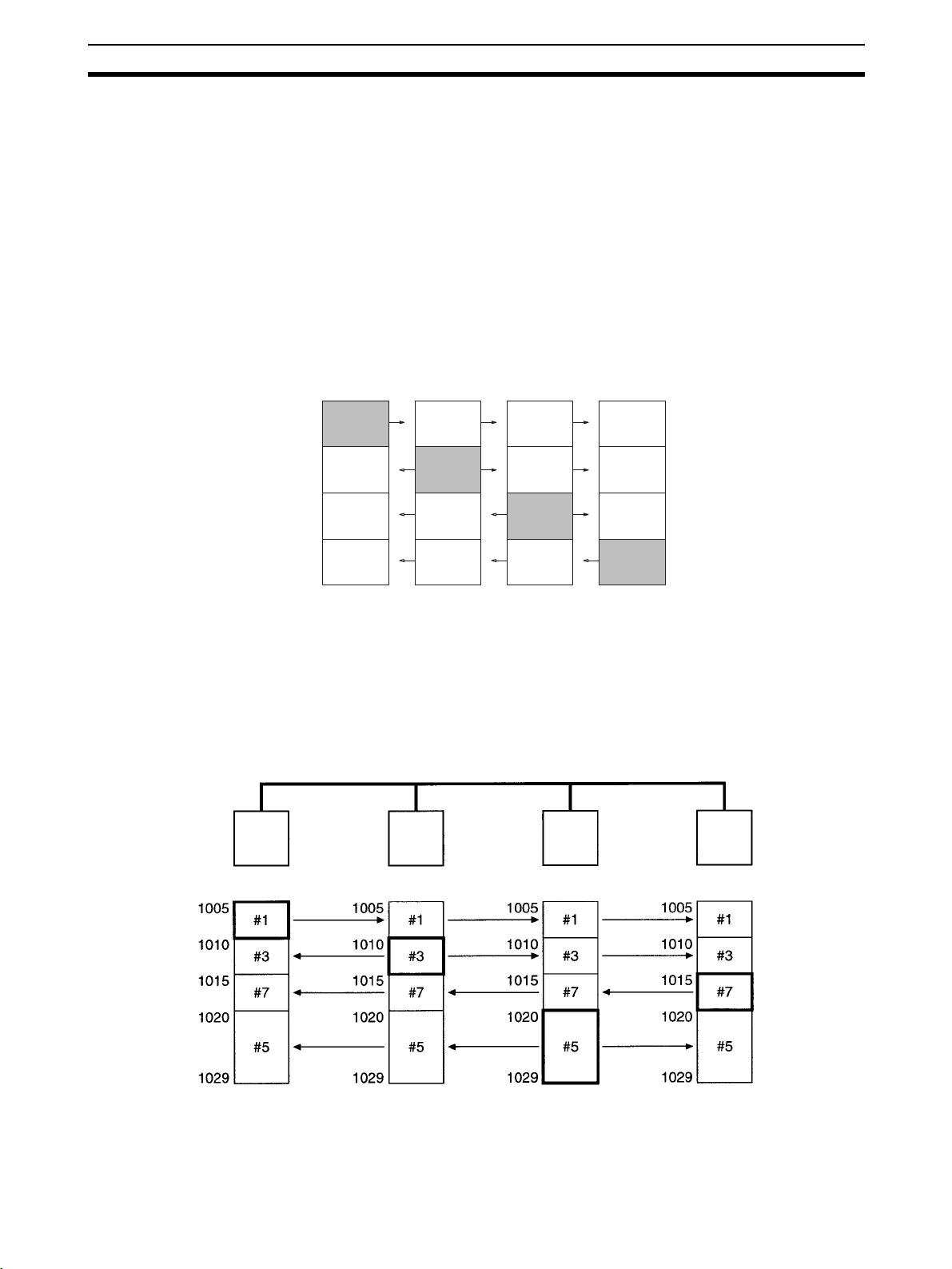
Data Link Area Allocations Section 4-6
4-6 Data Link Area Allocations
Data link area allocations when the data link functions are started up are carried out as shown below, depending on whether the startup node data link
table has been set automatically or by the user.
4-6-1 Automatic Settings
All nodes are allocated the same data link area depending on the number of
link words set in the startup node. When automatic allocations are made, the
settings in nodes other than the startup node are invalid. Send word data for
each node is sent to the receive words allocated to the same memory area
words at the other nodes, and stored there. The shaded areas in the following
diagram indicate the send words for each node.
Node 1
(CIO Area)
4-6-2 Manual Settings
The data link areas can be allocated as described in this section by using the
refresh parameter settings for each node.
Identical Allocations for
All Nodes
Node 1 Node 3 Node 5 Node 7
When editing data link table refresh parameters, set the same refresh parameters for all nodes. (Create refresh parameters for each node using the Support Software, even if the allocations are the same for all nodes. A copy
function is supported that will make identical settings easy.)
1000 to
1015
1016 to
1031
1032 to
1047
1048 to
1063
Node 2
(CIO Area)
1000 to
1015
1016 to
1031
1032 to
1047
1048 to
1063
Node 3
(CIO Area)
1000 to
1015
1016 to
1031
1032 to
1047
1048 to
1063
Node 4
(CIO Area)
1000 to
1015
1016 to
1031
1032 to
1047
1048 to
1063
(Node 1 data)
(Node 2 data)
(Node 3 data)
(Node 4 data)
CIO Area CIO Area CIO Area CIO Area
49
Page 67

Data Link Area Allocations Section 4-6
Different Allocations for
Each Node
To limit receiving from specified nodes and send only or receive only from
specified nodes, change the refresh parameters for each node. In the following example, node 5 does not receive data from node 6, and node 6 does not
receive data from node 2. Also, node 8 only receives data.
Node 2 Node 5 Node 6 Node 8
CIO Area CIO Area CIO Area CIO Area
DM Area DM Area DM Area DM Area
Note The send area for node 8 has specified 0 for both the CIO Area and DM Area
Creating Two or More Data
Link Groups in One
Network
50
in the common link parameters.
Only nodes with refresh parameters will participate in the data links.
Although the node order in the manual settings can be changed as you wish,
the Data Link Area must be created in continuous areas.
The common link parameters are the same for each network. Consequently,
multiple data link groups cannot be created in a SYSMAC LINK Network. Virtual data link groups, however, can be created using the refresh parameters.
As shown below, if you divide the groups and set the send and receive words
for the nodes within each group, you can set multiple data link groups, as
shown in the following diagram.
Page 68

Data Link Area Allocations Section 4-6
It is still necessary to set the total data link words for group 1 and group 2 to
within the maximum number of link words (2,966 words).
Group 1
Node 1 Node 2
CIO Area CIO Area CIO Area CIO Area
Node 3 Node 4
Group 2
4-6-3 Refreshing Data Links with Automatic Settings
Data link refreshing with automatic settings is carried out for all nodes in the
data link areas that have been specified.
In the following example, only nodes 2, 4, 5, and 6 are participating in the data
links. Nodes 1, 3, 7, and 8, however, will also be refreshed and words for them
cannot be used for other applications. If no data is received, nodes 1, 3, 7,
and 8 are refreshed with 0.
System Configuration
Node 2 Node 4 Node 5 Node 6
Refreshing for the above setup will be as shown below:
CIO Area
Node 1
Node 2
Node 3
Node 4
Node 5
Node 6
Node 7
Node 8
1000 to 1007
1008 to 1015
1016 to 1023
1024 to 1031
1032 to 1039
1040 to 1047
1048 to 1055
1056 to 1063
Refreshed.
Note When using the SYSMAC LINK Units listed below, the node areas outside of
the node address allocated the lowest word addresses (node 2 in the above
example) and the node allocated the highest word addresses (node 6 in the
above example) are not refreshed (nodes 1, 7, and 8 in the above example),
and can be used for other applications in the CPU Unit of these SYSMAC
LINK Units.
• CVM1/CV-series SYSMAC LINK Unit (CV500-SLK11/21)
• C200HX/HG/HE SYSMAC LINK Unit (C200HW-SLK13/14/23/24)
51
Page 69

Data Link Area Allocations Section 4-6
• C1000H/C200HF/C2000H SYSMAC LINK Unit (C1000H-SLK11/21-V1)
4-6-4 Refreshing Data Links with Manual Settings
When manual settings have been made, data link areas will be refreshed for
all nodes specified in the refresh parameters.
In the following example, only nodes 3, 4, 6, and 7 are participating in the data
links. Nodes 1, 2, 5, and 8, however, will also be refreshed and words for them
cannot be used for other applications. If no data is received, nodes 1, 2, 5,
and 8 are refreshed with 0.
Node 3 Node 4 Node 6 Node 7
CIO Area
0500
0510
0515
0520
0530
0535
0545
0550
0555
Data Link words for node 3
Node 5
Node 7
Node 3
Node 6
Node 8
Node 4
Node 1
Node 2
Range where the
data is refreshed
Note When using the SYSMAC LINK Units listed below, the node areas outside of
the node allocated the lowest word addresses (node 7 in the above example)
and the node allocated the highest word addresses (node 4 in the above
example) are not refreshed (nodes 1, 2, and 5 in the above example), and can
be used for other applications in the CPU Unit of these SYSMAC LINK Units.
• CVM1/CV-series SYSMAC LINK Unit (CV500-SLK11/21)
• C200HX/HG/HE SYSMAC LINK Unit (C200HW-SLK13/14/23/24)
• C1000H/C1000HF/C2000H SYSMAC LINK Unit (C1000H-SLK11/21-V1)
52
Page 70

Data Link Table Example Section 4-7
4-7 Data Link Table Example
In this example, the refresh parameters differ from node to node, so the data
link tables will also differ from node to node. There are four nodes in the network (2, 5, 6, and 8), but some nodes will not receive data from all other
nodes. The settings for the common link and refresh parameters are shown
after the data flow.
Node 5Node 2 Node 6 Node 8
CIO
Area
CIO Area CIO Area CIO Area CIO Area
1000
1010
1025
1029
D00000
D00010
D00020
D00025
D00029
1000
2
1010
5
6
DM Area DM Area DM Area DM Area
2
5
6
8
1025
1029
D00020
D00030
D00040
D00044
2
5
6
2
5
6
1005
1020
1024
D00000
D00010
D00014
5
6
5
6
Words written by local node
Words read by local node
1010
1015
1025
1039
D00000
D00005
D00015
D00025
D00029
6
2
5
6
2
5
8
In this example, node 5 does not receive data from node 8, and node 6 does
not receive data from node 2. Also, node 8 only receives CIO Area data from
the other nodes
Create the data link tables for each participating node using CX-Net in CXProgrammer. The following settings are required.
• Local node send size
• PLC type
• Local node data link start address
• Refresh node order
53
Page 71
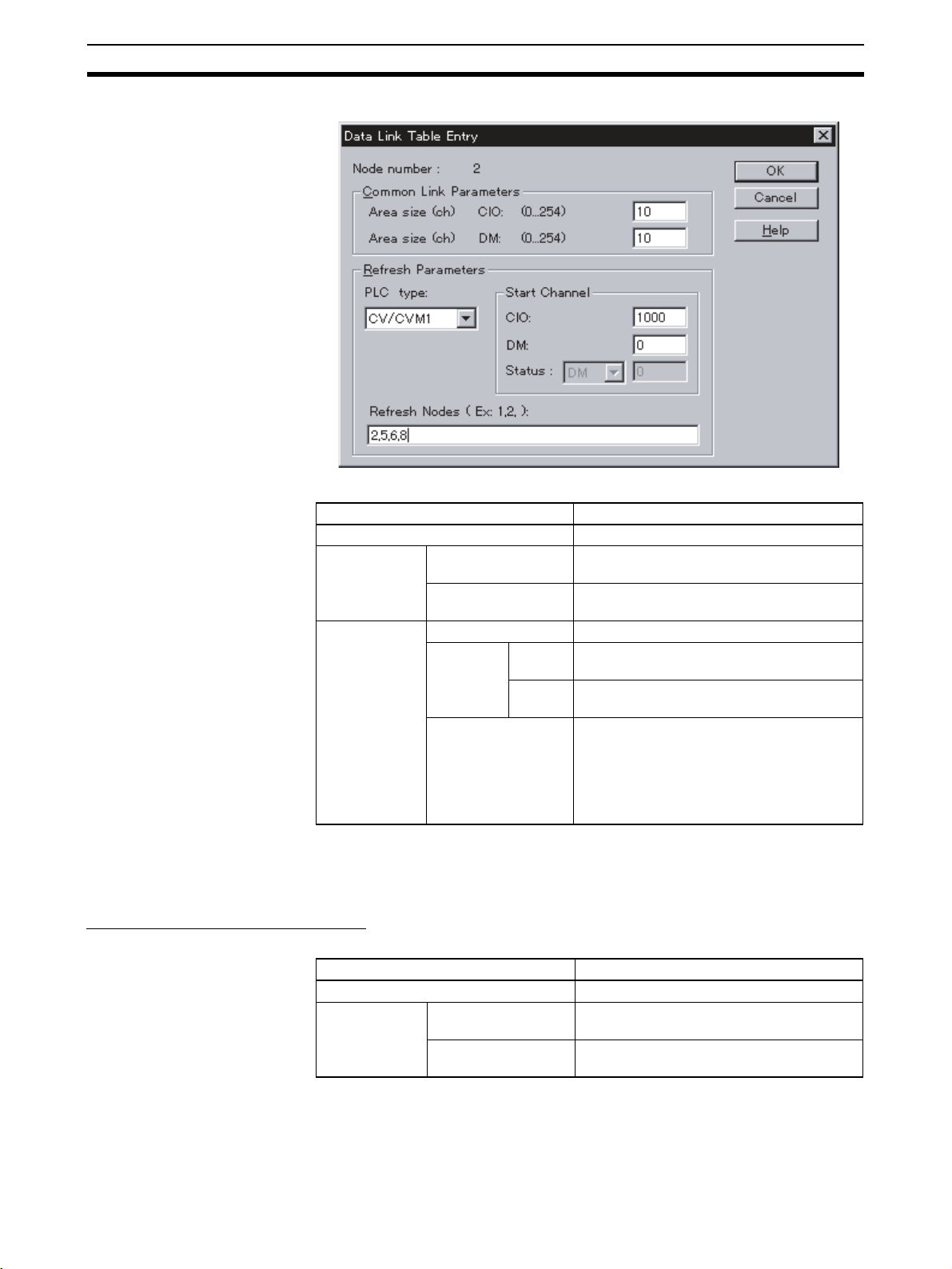
Data Link Table Example Section 4-7
Example of Node 2 Settings
Node 2 Table
Item Setting
Node address Local node address: 2
Common link
parameters
Refresh parameters
Number of words in
CIO Area
Number of words in
DM Area
PLC type Select “CV/CVM1”
Start word CIO CIO Area local node data link start address:
DM DM Area local node data link start address:
Refresh nodes Node refresh order: 2, 5, 6, 8
CIO Area local node send size: 10 words
DM Area local node send size: 10 words
CIO 1000
D00000
Node addresses are listed in order with the
starting node address first. Because here
the local node is listed first, node 2 will first
send data and then received data in order
from nodes 5, 6, and 8.
Note When setting data link tables for CS-series SYSMAC LINK Units with CX-Pro-
grammer Ver. 1.2 (Service Pack 1), set the PLC type to CV/CVM1. With CXProgrammer Ver. 2.0 or later, it is possible to set a CS-series PLC type.
Setting Tables for Other Nodes
Node 5 Table
Node address Local node address: 5
Common link
parameters
54
Item Setting
Number of words in
CIO Area
Number of words in
DM Area
CIO Area local node send size: 15 words
DM Area local node send size: 10 words
Page 72

Controlling Data Links Section 4-8
Item Setting
Refresh parameters
Node 6 Table
Node address Local node address: 6
Common link
parameters
Refresh parameters
Node 8 Table
Node address Local node address: 8
Common link
parameters
Refresh parameters
PLC type Select “CV/CVM1”
Start word CIO CIO Area local node data link start address:
DM DM Area local node data link start address:
Refresh nodes Node refresh order: 2, 5, 6
Item Setting
Number of words in
CIO Area
Number of words in
DM Area
PLC type Select “CV/CVM1”
Start word CIO CIO Area local node data link start address:
DM DM Area local node data link start address:
Refresh nodes Node refresh order: 5, 6
Item Setting
Number of words in
CIO Area
Number of words in
DM Area
PLC type Select “CV/CVM1”
Start word CIO CIO Area local node data link start address:
DM DM Area local node data link start address:
Refresh nodes Node refresh order: 6, 2, 5, 8
CIO 1000
D00020
CIO Area local node send size: 5 words
DM Area local node send size: 5 words
CIO 1005
D00000
CIO Area local node send size: 0 words
(nothing set)
DM Area local node send size: 5 words
CIO 1010
D00000
4-8 Controlling Data Links
It is necessary to start the data links after finishing the data link settings.
Starting the data links is carried out by any one of the following three startup
operations. This is true for both manual settings and automatic settings.
• From the DM parameter software switches
• By sending a command
• By using the Support Software
Note (1) The data link mode (manual settings or automatic settings) and the data
link system are determined by the data link settings for the startup node.
(2) Be sure to set the data link mode (manual settings) and the data link table
in the DM parameter area of the startup node when using manual settings.
(3) Be sure to set the data link mode (automatic settings) and the number of
data link words in the DM parameter area of the startup node when using
automatic settings.
(4) The data links will not operate unless the settings are correct.
55
Page 73

Data Link Status Section 4-9
!Caution Check the following before starting the data links. If the data link table settings
or the DM parameter settings are unsuitable, there is a risk of injury due to
unanticipated operation of the system.
(a) Manual settings: Check that suitable data link tables have been
set in each data link node. Check that data link tables have been
deleted for nodes not participating in the data links.
(b) Automatic settings: Check that suitable DM parameters have
been set in the data link startup node.
!Caution Even if the data link table settings or the DM parameter settings are suitable,
check that there will be no adverse effects on the controlled equipment before
starting or stopping the data links.
4-8-1 DM Parameter Area Software Switches
To start the data links, turn ON the Data Link Start/Stop Bit in DM parameter
area in the CPU Unit of the node you wish to use as the startup node.
To stop the data links, turn OFF Data Link Start/Stop Bit in DM parameter
area in the CPU Unit of a node participating in the data links.
The Data Link Start/Stop Bit can be turned ON and OFF using the user program, Support Software, or a Programming Console (refer to 4-4-3 Data Link
Start/Stop Bit).
Word: D30000 + (100 x unit number)
Bit
Data Link Start/Stop Bit
The data links will start when the bit is turned ON,
or if it is already ON when the power is turned ON.
The data links will be stopped when the bit
is turned OFF.
Refer to Section 4-12 CX-Programmer Procedures or CX-Programmer Operation Manual for actual procedures.
4-8-2 DATA LINK START/HALT Commands
Data links can be started by sending a DATA LINK START command from a
host computer or by executing the CMND(490) instruction to send the command from a PLC to the node you wish to use as the startup node.
Data links can be stopped by sending a DATA LINK HALT command from a
host computer or by executing the CMND(490) instruction to send the command from a PLC to a node participating in the data links.
Note Refer to 6-4-1 DATA LINK START and 6-4-2 DATA LINK HALT for details.
4-8-3 CX-Net in CX-Programmer
−: Other settings
The data link can be started or stopped from the Support Software. Refer to
CX-Programmer Operation Manual for details.
4-9 Data Link Status
The status of the local node and the nodes in the data links can be checked
from the data link status area in the words allocated to the SYSMAC LINK
Unit as a CPU Bus Unit.
56
Page 74

Data Link Status Section 4-9
4-9-1 Data Link Status
The following status is indicated through the ON/OFF status of each bit. Refer
to Word Configuration later in this section for specific allocations.
Item Bits Contents
Node status CPU Unit
Local node
status
Network status
Operating
Flag
CPU Unit
Error Flag
Data Link
Communications Error
Flag
Data Link
Active Flag
Local Node
Data Link
Active Flag
Startup
Node
Address
0, 4, 8, 12 ON if the CPU Unit of the node is operating (RUN or MONITOR
1, 5, 9, 13 ON if there is a fatal error in the CPU Unit of the node.
2, 6, 10, 14 ON if the node has a communications error and is not participating
3, 7, 11, 15 ON if the node has participated in the data links, even if only once.
Bit 15 of first
allocated
data link +
23 words
Bits 8 to 13
of first allocated data
link word +
23
mode).
OFF if the CPU Unit of the node is in PROGRAM mode.
• This flag is invalid if the Data Link Communications Error Flag for
the node is ON.
• If a fatal error (including an FALS instruction) occurs during operation, this flag will remain ON.
• When using this flag in programming, take an AND of NO conditions of it and the local node’s Data Link Active Flag.
OFF when the CPU Unit of the node is operating normally.
• This flag is invalid if the Data Link Communications Error Flag for
the node is ON.
• When using this flag in programming, take an AND of NO conditions of it and the local node’s Data Link Active Flag.
in the network (if the designated node is not sending data link data,
communications from that node are assumed to be in error).
OFF when the CPU Unit for the node is operating normally (data
link data is being sent continuously from the node).
• To check participation of a node in the data links, take an AND of
a NO condition of this flag and a NC condition of the Data Link
Active Flag.
OFF if the node has not yet participated in the data links.
• This bit turns ON once the node has participated in the data link,
and remains ON even if the node is no longer participating (used
to check system startup). Consequently, this flag cannot be used
to check the current participation status of a node in the data
links.
• When using this flag in programming, take an AND of NO conditions of it and the local node’s Data Link Active Flag.
ON if the node is participating in the data links.
OFF if the node is not participating in the data links.
• If this flag is OFF, local communications will not be operating normally, so there is no guarantee that the status of other flags will be
correct. Consequently, be sure to use this flag with an AND condition to check the status of other flags.
Startup node addresses 1 to 62 are stored as 1 to 3E Hex.
Note (1) The Data Link Active Flag is for checking the data link system. It is not
designed to check for data link errors. To check for data link errors, use
the Data Link Communications Error Flag.
(2) The CPU Unit Run Flag, CPU Unit Error Flag, Data Link Communications
Error Flag, and Data Link Active Flag are valid only if the Local Node Data
Link Active Flag is ON. Be sure to use the Local Node Data Link Active
Flag with an AND condition when using any of these flags in programming.
57
Page 75

Data Link Status Section 4-9
Program Example
Checking Data Link
Participation Status
Checking for Data Link
Errors in any Node
To check participation of any one node in the data links, take an AND of a NO
condition of the Local Node Data Link Active Flag and the Communications
Error Flag for each node as shown below.
Node A
Data Link Active Flag
Node A: Participating in data links
Local Node Data
Link Active Flag
Node A Communications
Error Flag
Node B Communications
Error Flag
Node n Communications
Error Flag
Node B
Data Link Active Flag
Node n
Data Link Active Flag
Node B: Participating in data links
Node n: Participating in data links
To check for an error in any node in the data links, take an OR of a NC condition of the Local Node Data Link Active Flag and the Communications Error
Flags for all nodes.
Data link error in one
Local Node Data
Link Active Flag
Node A Communications Error Flag
or more nodes
Outputting Local Node
Errors
Node B Communications Error Flag
Node n Communications Error Flag
The following example program section shows one way to output and error
signal when data links stop for the local node.
Local Node Data
Link Active Flag
Communications
Error Flag
Bit indicating data link
error in local node
Bit indicating data link
error in local node
58
Page 76

Data Link Status Section 4-9
4-9-2 Word Structure
The following table shows the data link status in memory. The numbers within
the table are in order of the nodes are set in the data link table (refresh parameters). These will correspond to the node addresses when using automatic
settings.
The data link status area corresponds to the first word of the words allocated
to the SYSMAC LINK Unit as a CPU Bus Unit +8 to +23.
Word: CIO 1500 + (25 x unit number) +8 to +23.
Word Bits 00 to 03 Bits 04 to 07 Bits 08 to 11 Bits 12 to 15
m+8 Link No. 1 Link No. 2 Link No. 3 Link No. 4
m+9 Link No. 5 Link No. 6 Link No. 7 Link No. 8
m+10 Link No. 9 Link No. 10 Link No. 11 Link No. 12
m+11 Link No. 13 Link No. 14 Link No. 15 Link No. 16
m+12 Link No. 17 Link No. 18 Link No. 19 Link No. 20
m+13 Link No. 21 Link No. 22 Link No. 23 Link No. 24
m+14 Link No. 25 Link No. 26 Link No. 27 Link No. 28
m+15 Link No. 29 Link No. 30 Link No. 31 Link No. 32
m+16 Link No. 33 Link No. 34 Link No. 35 Link No. 36
m+17 Link No. 37 Link No. 38 Link No. 39 Link No. 40
m+18 Link No. 41 Link No. 42 Link No. 43 Link No. 44
m+19 Link No. 45 Link No. 46 Link No. 47 Link No. 48
m+20 Link No. 49 Link No. 50 Link No. 51 Link No. 52
m+21 Link No. 53 Link No. 54 Link No. 55 Link No. 56
m+22 Link No. 57 Link No. 58 Link No. 59 Link No. 60
m+23 Link No. 61 Link No. 62 Bits 08 to 13: Address of startup
node (01 to 3E Hex)
Bit 15: Local Data Link Active
Flag (ON: data link active;
OFF: data link inactive)
The status of the bits allocated to each node is as follows:
Bit 00, 04, 08, or 12: CPU Unit Operating Flag
Bit 01, 05, 09, or 13: CPU Unit Error Flag
Bit 02, 06, 10, or 14: Data Link Communications Error Flag
Bit 03, 07, 11, or 15: Data Link Active Flag
The actual words allocated to each node address for data link status are
shown in the following table.
Unit No. Words Unit No. Words
0 CIO 1508 to CIO 1523 8 CIO 1708 to CIO 1723
1 CIO 1533 to CIO 1548 9 CIO 1733 to CIO 1748
2 CIO 1558 to CIO 1573 10 CIO 1758 to CIO 1773
3 CIO 1583 to CIO 1598 11 CIO 1783 to CIO 1798
4 CIO 1608 to CIO 1623 12 CIO 1808 to CIO 1823
5 CIO 1633 to CIO 1648 13 CIO 1833 to CIO 1848
6 CIO 1658 to CIO 1673 14 CIO 1858 to CIO 1873
7 CIO 1683 to CIO 1698 15 CIO 1883 to CIO 1898
If the Local Node Data Link Active Flag (bit 15 of first word +23) is OFF, the
data link status will be maintained as it was immediately before operation
stopped. This may not be the same as the actual current status. When using
59
Page 77

Data Link Precautions Section 4-10
the data link status, first check that the Local Node Data Link Active Flag is
ON.
4-10 Data Link Precautions
Be sure to consider the precautions listed below when activating a data link or
adding a node to an existing data link.
Setup and Activation Be sure to consider the precautions listed below when setting up and activat-
ing a data link.
1,2,3... 1. Refresh parameters must be set for each node in the data link when man-
ually generating data link tables. When a data link is started in a node that
does not have a data link table, a data link table error will occur and the
LNK indicator on that node will flash.
Refresh parameters must be set for all nodes that are included in the common link parameters in the startup node.
2. When data links are automatically generated, the node addresses of all the
nodes in the data link must be in the range resulting from the Communication Unit Settings.
For example, if the settings divide the data link area among nodes number
1 to 4 (16 CIO words and 32 DM words), node 5 cannot participate in the
data link.
3. With manual generation of data link tables, the node address of the local
node must be included in the local refresh parameters.
4. If the beginning CIO or DM word in the refresh parameters is set too large,
the CIO or DM Area will be exceeded during automatic allocation of link
words.
If the data area is exceeded in the startup node, the LNK indicator on the
startup node will flash and the data link will not operate. If the data area is
exceeded in another node, the LNK indicator on that node will flash and it
will not participate in the data link.
5. If the communications cycle time in data link tables is not generated automatically, and the setting for communications cycle time is too short, the
CS-series SYSMAC LINK Unit (CS1W-SLK11/21) will not participate in the
data links. The LNK indicator on the Unit will flash quickly, and a data link
table communications cycle time settings error (021D Hex) will be registered in the error log. If this CS-series SYSMAC LINK Unit is the startup
node for the data link, the data link will not be activated. The minimum possible communications cycle time setting can be obtained using the following calculation:
Minimum possible communications cycle time setting =
Maximum node address
+ Number of polled Units
+ Number of Link Units
+ Total number of words in link area
+ 5.322 (ms)
Round up the result of this calculation to obtain a value in milliseconds.
× 0.01
× 0.25
× 0.161
× 0.01
60
Page 78

Data Link Precautions Section 4-10
The data link table communications cycle time setting error registered in
the error log will contain the following information:
Error code Detail code
1st byte 2nd byte
021D Hex Communications cycle
time set in the data link status (Unit: ms, 2-digit hexadecimal)
Minimum possible communications cycle time setting (Unit: ms, 2-digit
hexadecimal)
The value in the 2nd byte of the detail code for 021D registered in the error
history will be the minimum possible communications cycle time setting.
For example, if the communications cycle time is set to 5 ms, and the LNK
indicator starts flashing quickly, an error code of “021D 0512” will indicate
that the minimum possible communications cycle time setting is 18 ms
(12 Hex).
021D 0512
Error code
Minimum possible communications cycle time setting
Communications cycle time set
Adding Nodes Be sure to consider the precautions listed below when adding a node to active
data links.
1,2,3... 1. The node address of the node being added must be in the common link
parameters of the data links.
2. Set data link tables in the node being added. This is not necessary, however, when using automatic settings with the startup node, although it is
necessary to include the node being added in the table of nodes participating in the data link in the automatic settings.
3. The common link parameters for the node being added must be the same
as for the common link parameters already in operation. If the common link
parameters for the node being added are different from the common link
parameters already in operation, the node being added cannot participate
in the data link. Refer to the example below.
4. If the communications cycle time for the data link tables is manually set
when a CS-series SYSMAC LINK Unit is to be added to the data links,
make sure that the value set is not below the minimum possible communications cycle time setting. For details of the values that can be set, refer to
the previous section, Setup and Activation.
61
Page 79

Data Link Characteristics Section 4-11
Adding a Node to a Data Link
Node 1 Node 2 Node 3 Node 4
1000
1010
1020
1030
1039
CIO Area
1
2
3
4
CIO Area CIO Area
1000
1010
1020
1030
1039
1
2
3
4
The number of send words for node 4 is set as 20 words in the common link
parameters, but the number of send words is set as 10 words in the common
link parameters for other nodes that are already operating. Consequently,
node 4 will not participate in the data link network.
4-11 Data Link Characteristics
4-11-1 Data Link Communications Cycle Time
Data link servicing is given priority in SYSMAC LINK Systems. The communications time for a data link can thus be maintained as a constant, regardless
of whether or not SEND(90), RECV(98), and CMND(490) are used. Fixing the
data link communications time at a constant value fixes the data link I/O
response time as well.
The communications cycle time can be set either automatically (the default) or
controlled externally.
Startup node
1000
1010
1020
1030
1039
Participating nodes
CIO Area
1
2
3
4
1000
1010
1020
1030
1049
1
2
3
4
Automatic Generation
62
When data link tables have been generated automatically, the communications time will be as follows for systems using coaxial cable:
No. of nodes Data link areas
CIO and DM Areas CIO Area only DM Area only
2 19 ms 17 ms 18 ms
4 19 ms 17 ms 18 ms
8 19 ms 18 ms 18 ms
16 19 ms 18 ms 19 ms
The communications time will be as follows for systems using optical fiber
cable:
No. of nodes Data link areas
CIO and DM Areas CIO Area only DM Area only
2 21 ms 20 ms 21 ms
4 22 ms 20 ms 21 ms
8 22 ms 21 ms 21 ms
16 22 ms 21 ms 22 ms
Page 80

Data Link Characteristics Section 4-11
Manual Generation
When data link tables have been generated manually, the communications
cycle time can be set to a constant value or generated automatically.
The communications cycle time can be set as a constant from 5 to 255 ms in
increments of 1 ms using the Support Software to eliminate variations caused
by noise or other factors. When the communications cycle time is not set as a
constant, it will be generated automatically according to the equations below.
Round the result of the calculation to the nearest millisecond.
Communications cycle time (coaxial cable systems) =
Maximum node address
× 0.654 ms + number of polled units × 0.75 ms + number of Link Units
× 0.056 ms + total number of words × 0.01 ms + 1.322 ms
Communications cycle time (optical fiber cable systems) =
maximum node address
ms
+ number of polled units
+ total number of words
Note The present and maximum values of the communications cycle time can be
monitored from the Support Software.
Example Calculations The examples below calculate the communications cycle time for both coaxial
and optical fiber cable with the following characteristics:
Maximum node address: . . . . . . 62
Maximum number of frames: . . .10
Number of polled units: . . . . . . . 4
Number of Link Units . . . . . . . . . 32
Total number of words . . . . . . . . 2,000
Communications cycle time (coaxial cable systems) =
× 0.085 ms + 10 × 0.654 ms + 4 × 0.75 ms + 32 × 0.056 ms + 2000 ×
62
0.01 ms + 1.322 ms
= 37.924 ms (38 ms after rounding)
Communications cycle time (optical fiber cable systems) =
× 0.1115 ms + 10 × 0.77 ms + 4 × 0.75 ms + 32 × 0.056 ms + 2000 ×
62
0.01 ms + 1.322 ms
= 40.727 ms (41 ms after rounding)
× 0.085 ms + maximum number of frames
× 0.1115 ms + maximum number of frames × 0.77
× 0.75 ms + number of Link Units × 0.056 ms
× 0.010 ms + 1.322 ms
Note Data links might not operate correctly if the communications cycle time is set
to a value shorter than that generated automatically by the system. If the LNK
indicator on the front of a CS-series SYSMAC LINK Unit (CS1W-SLK11/12)
flashes quickly (at approximately 100-ms intervals), either automatically set
the communications cycle time for the data link table, or manually set the
communications cycle time to a longer value.
Changing the Communications Cycle Time
When the communications cycle time is generated automatically, it can be
changed by changing the other network parameters on the Support Software.
The default values and setting ranges of the other network parameters are
shown in the table below.
Network parameter Default value Setting range
Maximum node address 62 2 to 62
Number of polled units 4 1 to 62
Maximum number of frames 10 5 to 255
Use the following formulas to calculate the change in the communications
cycle time that results from a change in other network parameters. A positive
63
Page 81

Data Link Characteristics Section 4-11
result indicates the communications cycle time has been decreased and a
negative result indicates it has been increased. Round the result of the calculation to the nearest millisecond.
Change of the communications cycle time (coaxial cable systems) =
(old maximum node address - new maximum)
+ (old maximum number of frames - new maximum)
+ (old number of polled units - new number)
Change of the communications cycle time (optical fiber cable systems) =
(old maximum node address - new maximum)
+ (old maximum number of frames - new maximum)
+ (old number of polled units - new number)
Example Calculations The examples below calculate the change of the communications cycle time
for both coaxial and optical fiber cable when the other network parameters are
changed as shown below:
Maximum node address: . . . . . .Changed from 62 to 16
Maximum number of frames: . . .Changed from 10 to 13
Number of polled units: . . . . . . .Changed from 4 to 5
Change of the communications cycle time (coaxial cable systems) =
(62 – 16)
× 0.085 ms + (10 – 13) × 0.654 ms + (4 – 5) × 0.75 ms =
1.198 ms (1 ms after rounding)
Change of the communications cycle time (optical fiber cable systems) =
(62 – 16)
× 0.1115 ms + (10 – 13) × 0.77 ms + (4 – 5) × 0.75 ms =
2.069 ms (2 ms after rounding)
× 0.085 ms
× 0.654 ms
× 0.750 ms
× 0.1115 ms
× 0.77 ms
× 0.75 ms
Note (1) If the maximum node address is set to a value less than the node address
of any nodes in the data link, those nodes will no longer be part of the
data links.
(2) If the maximum number of frames is set too low, errors might occur during
the execution of operations such as SEND(90), RECV(98), and
CMND(490) instructions, internode echo tests, and remote monitoring.
(3) Lowering the number of polled units will increase the delay between re-
setting a Unit or turning on its PLC’s power and its entrance into the network.
4-11-2 Data Exchange Timing
This section explains data link timing when using data links between SYSMAC LINK Units and a CPU Unit.
With a CS-series PLC, data exchange with the SYSMAC LINK Unit is performed by interrupt processing during the peripheral servicing time in the CPU
Unit cycle time. Data exchange timing is as follows:
PLC processing
Basic processing
Execution
I/O refreshing Basic processing
PLC cycle time
CPU Bus
Unit service
Interrupt processing
for data exchange
Programming
Device/Host Link
service
Execution
64
If interrupt processing for data exchange is executed, the PLC cycle time will
be lengthened by the time required for the interrupt processing.
Page 82

Data Link Characteristics Section 4-11
Data Processing Time The time required for interrupt processing for data exchange (data processing
time) can be roughly estimated as shown in the following table.
Data link scale Equation for estimating data processing time
Data link is established for both areas 1 and 2 0.001 × Total number of data link words + 1.7 (ms)
Data link is established for only area 1 or area 2 0.001 × Total number of data link words + 1.4 (ms)
4-11-3 Calculation Examples for Data Link I/O Response Times
In a SYSMAC LINK Unit data link, there is a slight time lag between the time
input is received at one node in the link and the time output is made from
another node in response to this input. This time lag is called the data link I/O
response time. In this section, examples illustrating how to calculate the minimum and maximum I/O response times are given for the configuration shown
below.
Coaxial cable
PLC 1
Input
Item Condition
Maximum node address 62
Number of polled nodes 4
Maximum number of frames 10
Number of participating nodes 8
Number of nodes participating in data links 8
Number of send words for area 1 8 words per node
Number of send words for area 2 16 words per node
Messages None
SYSMAC LINK
Unit
Node 1
LRXXX
Data link
Output
LRXXX
PLC 7
SYSMAC
LINK Unit
Node 7
OutputInput
The time required for each of the above items is given below:
Communications Cycle Time
62 × 0.085 + 10 × 0.654 + 4 × 0.75 + 8 × 0.056 + 192 × 0.01 + 1.322 = 18.5
≈ 19 ms (For details, refer to page 62.)
Input ON Response Time
This is the time between an input signal being received and the relevant input
bit actually turning ON. Taken as 0 ms (min.) to 1.5 ms (max.) in this example.
Output ON Response Time
This is the time between the relevant output bit turning ON in the CPU Unit
and the output signal actually being sent. Taken to be 0 ms (min.) to 1.5 ms
(max.) in this example.
65
Page 83

Data Link Characteristics Section 4-11
Scan Time for PLC 1
Taken to be 25 ms in this example.
Scan Time for PLC 7
Taken to be 10 ms in this example.
Maximum Data Link I/O Response Time
Input
(1)
Instruction
execution
I/O processing
Data exchange
Scan time for PLC 1
(2)
Communications cycle
(3)
Scan time for PLC 7
Instruction
execution
Instruction execution
Input ON response time 1.5 ms
Scan time for PLC 1 × 2 25 ms × 2
Communications cycle time × 2 19 ms × 2
Scan time for PLC 7 × 2 (see note a) below) 10 ms × 2
Output ON response time 15 ms
Total (data link I/O response time) 124.5 ms
Output
The following delays occur at 1, 2, and 3 in the above diagram:
1,2,3... 1. The input bit turns ON just after a scan and so the time required for one
more scan elapses before the input is processed. Therefore a multiplication factor of 2 is applied to the scan time, as shown in the above table.
2. Processing for the input data is exchanged immediately after the right to
transmit is transferred from PLC 1, and so the time required for communications is extended by approximately one communications cycle. Therefore a multiplication factor of 2 is applied to the communications cycle time,
as shown in the above table.
3. Data is exchanged data with PLC 7 just after one scan and so the time required for one more scan elapses before output processing is performed.
Therefore a multiplication factor of 2 is applied to the scan time, as shown
in the above table.
Note (a) A multiplication factor of 3 (not 2) is applied to the scan time for
PLC 7 if it is longer than the communications cycle time.
(b) The I/O response time will also be affected by noise and other fac-
tors.
66
Page 84

CX-Programmer Procedures Section 4-12
Minimum Data Link I/O Response Time
Input
Scan time for PLC 1
Communications cycle
Scan time for PLC 7
Output
Maximum transmission delay time
Input ON response time --Scan time for PLC 1 25 ms
Communications cycle time --Scan time for PLC 7 10 ms
Output ON response time --Total (data link I/O response time) 35 ms
4-12 CX-Programmer Procedures
This section describes the procedures from creation of data link tables to
starting up data links using CX-Net in CX-Programmer.
Here, the procedure for CX-Net in CX-Programmer Ver. 1.2 (Service Pack 1)
is given as an example. The operations, windows, and setting items may vary
with the version of CX-Programmer.
4-12-1 Overall Procedure
If building SYSMAC LINK data links for the first time, make the settings using
the following procedure. It is necessary to create data link tables if using manually set data links.
Note There is no need to create data link tables when using automatic settings. If
using automatically set data links, set the DM parameter areas (DM area
words allocated to the SYSMAC LINK Unit as a CPU Bus Unit) using a Programming Console or the PLC Memory Window in CX-Programmer.
1,2,3... 1. Start CX-Net from the CX-Programmer by selecting Tools and then Net-
work Configuration Tool.
2. Open the CX-Server file (*.CDM) in CX-Net or create a new file in CX-Net
by selecting Project and then Open in CX-Net.
3. Start the Data Link Editor to create the data link tables by selecting Data
Link and then Editor.
• If creating the same data link tables in all nodes, start the Data Link
Engineer from the Data Link Editor by selecting Table and then Data
Link Engineer.
• If creating different data link tables for each node, create data link parameters for each node by editing tables for each node individually.
67
Page 85

CX-Programmer Procedures Section 4-12
4. Check the data link tables from the Data Link Editor by selecting Ta ble and
then Check.
5. Save the data link tables from the Data Link Editor by selecting File and
then Save or Save as.
6. Connect to the network from CX-Net by selecting PLC and then Open.
7. Read the data link tables and transfer them to the PLC using the Data Link
Setup Dialog Box from CX-Net. Select Data Links and then Setup.
8. Start the data links using the Data Link Status Dialog Box from CX-Net. Select Data Link and then Status.
Note Data link tables cannot be set for the C200H-SLK21 and C1000H-SLK21.
Refer to
9-3 Using the C200H-SLK21 or C1000H-SLK21 for details.
4-12-2 Data Link Settings
System Configuration
CX-Programmer
Node 1, CS-series PLC
Note The network settings for the three PLCs shown above have already been
saved in the CX-Server file (.CDM). For CX-Server file creation, refer to in the
CX-Programmer Operation Manual.
Opening CX-Server Files (.CDM)
Read the CX-Server file in CX-Net using the following procedure.
1,2,3... 1. Start CX-Net from the CX-Programmer by selecting Tools and then Net-
work Configuration Tool.
Node 2, CVM1 PLC
Node 3, CS-series PLC
SYSMAC LINK Network
68
Page 86

CX-Programmer Procedures Section 4-12
2. Open the CX-Server file (*.CDM) in CX-Net or create a new file in CX-Net
by selecting Project and then Open in CX-Net. In this example, Sample.cdm is used as the file name. The following dialog box will be displayed.
Creating Data Link Tables
Starting the Data Link Editor
1,2,3... 1. Select Data Link and then Editor. A dialog box for selecting the type of
Making Manual Settings
without Using the Data
Link Table Engineer
Create the data link tables for each node entered in the CX-Server file. In this
example, the data link tables are created automatically using the Data Link
Table Engineer, then the parameters are changed manually.
data link will appear.
2. Select SYSMAC LINK Data Link Table and then click the OK button. The
Data Link Editor [SYSMAC LINK] will start.
You can make Manual Settings without using the Data Link Table Engineer.
Create data link tables manually in the following cases.
• The send area size is different for each node participating in the data link.
• The send node order is not the same as the order of node addresses.
• There are nodes that are not receiving data.
69
Page 87

CX-Programmer Procedures Section 4-12
Refer to the following example for details.
CIO Area
Node 1 Node 2 Node 3
DM Area
Send (1)
Receive
(3)
Receive
(2)
Node 1 Node 2 Node 3
Send (1)
Receive
(3)
Receive
(2)
Receive
(1)
Receive
(3)
Send (2)
Receive
(1)
Receive
(3)
Send (2)
Receive
(1)
Receive
(2)
Send (3)
Receive
(1)
Receive
(2)
Send (3)
1,2,3... 1. Select Data Link and then Editor. A dialog box for selecting the type of
data link will appear.
70
Page 88

CX-Programmer Procedures Section 4-12
2. Select SYSMAC LINK Data Link Table and then click the OK button. The
Data Link Editor [SYSMAC LINK] will start.
3. Set the data link communications cycle time in the Cycle Time field under
Common Link. If you select Auto, the optimum communications cycle time
will be automatically calculated according to the data link tables. If you select Manual, set the time manually between 5 to 255 ms (refer to 4-11 Data
Link Characteristics for communications cycle time details).
4. Double click a node address in the Nodes field, or select Ta ble and then
Edit Table Item. The Data Link Table Entry Dialog Box will appear.
Note (a) If using CX-Programmer Ver. 1.2 (Service Pack 1), select CV/
CVM1 for the PLC type when using a CS-series SYSMAC LINK
Unit.
If a CV/CVM1 PLC is set, the manual settings words will be limited to the same words as for CVM1/CV, as follows:
CIO Area: CIO 0000 to CIO 2555
DM Area: D00000 to D24575
(b) CS-series PLC types can be specified with CX-Programmer Ver.
2.0 or later and so the above limitations to manual settings words
do not apply.
71
Page 89

CX-Programmer Procedures Section 4-12
Set the local node CIO Area send size in
words. Setting range: 0 to 254 words.
When this setting is 0, the local node will
not send CIO data (i.e., will receive only).
Set the local node DM Area send
size in words. Settings range: 0 to
254 words. When this setting is 0,
The node address selected for editing
If using CX-Programmer Ver. 1.2
(Service Pack 1), select CV/CVM1
for the PLC type when using a CSseries SYSMAC LINK Unit. The
words for manual settings will be
limited to the same words as for
CVM1 and CV-series PLCs.
If using CX-Programmer Ver. 2.0 or
later, CS-series PLC types can be
specified and so the above
limitations to words for manual
settings do not apply.
the local node will not send DM
data (i.e., will receive only).
Set the address of the first
word in the CIO Area data link
of the local node. Setting
range: CIO 0000 to CIO 2555.
Set the address of the first word
in the DM Area data link of the
local node. Setting range:
D00000 to D24575. (Setting
range with CX-Programmer Ver.
2.0 or later: D00000 to D32767.)
Set in order the node addresses with which the local node will refresh data, starting
with the data link start addresses set above. If the address of the local node is set,
it will send the specified word data to other nodes. If the address of another node is
set, the local node will receive the data sent by that node. For example, if you enter
3, 2, 1 as the refresh order, the node addresses will be allocated in the order 3, 2,
1, starting from the start address. If the local node address is 1, it will receive data
from node 3, then from node 2, and finally, it will send data itself). Always include
the local node in the refresh node order. Data will not be received from the local
node by another other node if the local node is not specified.
5. Enter the value in each field.
The following example shows settings for node 1.
72
Page 90

CX-Programmer Procedures Section 4-12
Node address Local node address: 1
Common link
parameters
Refresh
parameters
6. Set the settings for node 2 and 3 in the same way. The following example
shows the settings for node 2.
CIO Area size CIO Area local node send size: 20 words.
DM Area size DM Area local node send size: 30 words.
PLC type Select “CV/CVM1”
Start
word
Refresh
nodes
CIO CIO Area local node data link start address:
CIO 1000.
DM DM Area local node data link start address: D00500
Node refresh order: 1, 3, 2
Node addresses are listed in order with the starting
node address first. Because here the local node is
listed first, node 1 will first send data and then
received data in order from nodes 3 and then 2.
The following example shows the settings for node 3.
73
Page 91
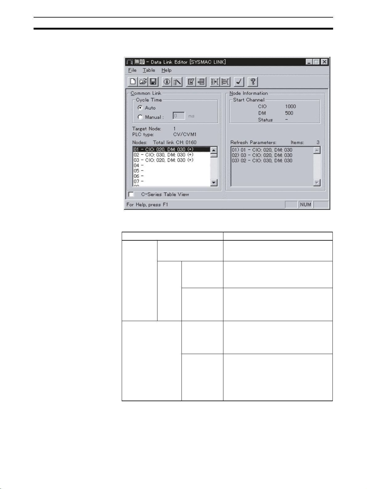
CX-Programmer Procedures Section 4-12
7. The following display will appear when the data link table settings have
been made for all nodes. The example shows node 1 selected.
Settings and Display
Contents
Item Contents
Common
Link: Com-
mon link
parameters
Node Information Start Channel:
Cycle Time:
Communications cycle
time
Ta rg e t
Node
Total link CH:
Total number of
link words
Nodes The number of send words is displayed for
Start words
Refresh
Parameters
Data link communications cycle time:
Select automatic or manual settings. Manual setting range: 5 to 255 ms.
Displays the total number of data link
words (CIO Area + DM Area). In the example, CIO 70 words + DM 90 words = 160
words.
each node. CIO: Number of CIO Area send
words. DM: Number of DM Area send
words. In the example, CIO: 20 send
words, DM: 30 send words.
Displays the words from which data links
start in the CIO and DM Areas for the
selected node. In the example, CIO 1000
and D00500 are displayed as the start
addresses.
Displays the order in which nodes are
refreshed in the second column from the
left. The values on the right are the number
of words received from the node in the CIO
Area and DM Area.
In this example, nodes are refreshed in the
order 1, 3, 2.
74
Page 92
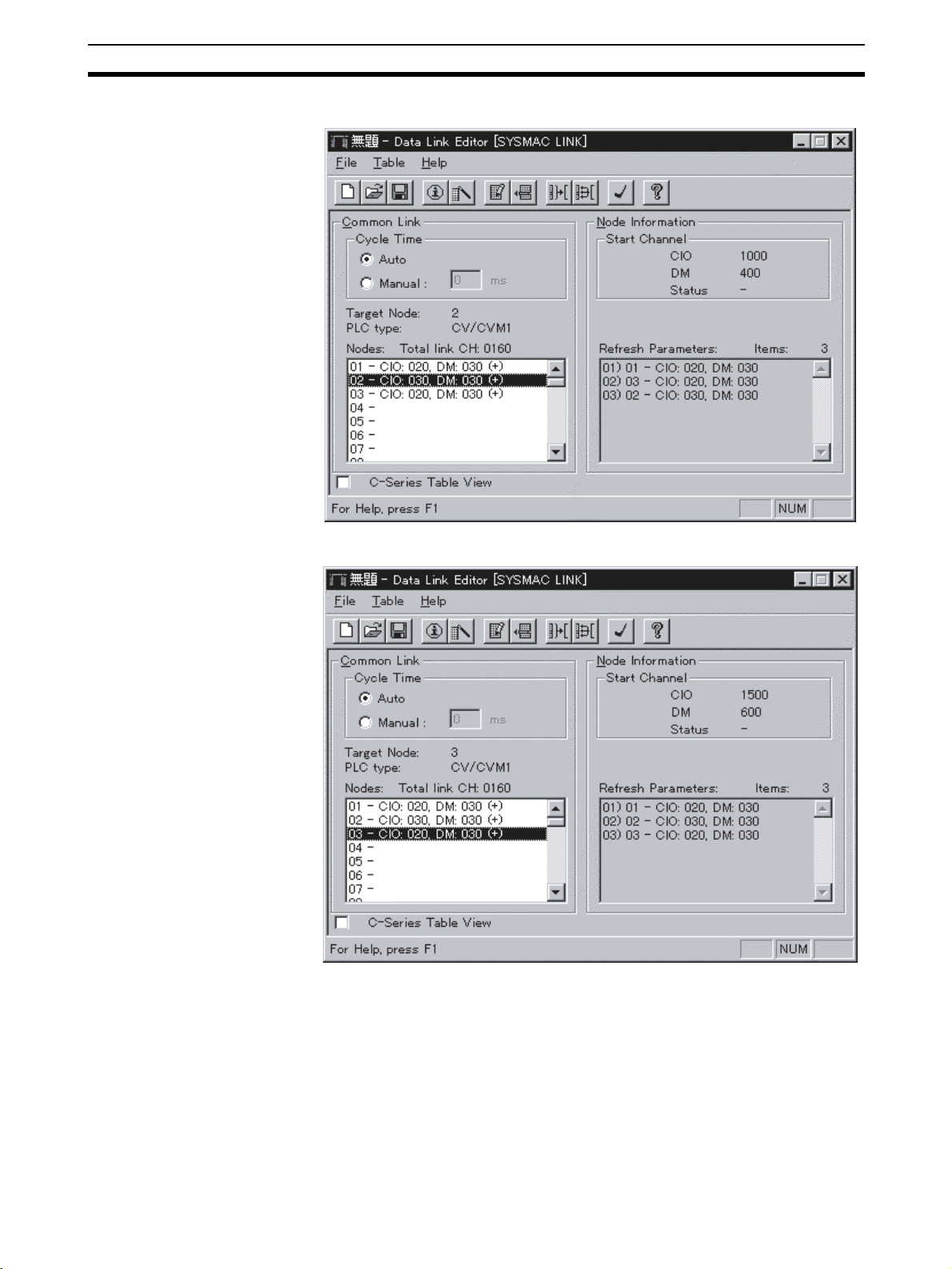
CX-Programmer Procedures Section 4-12
The following example shows the display for node 2.
Using the Data Link Table
Engineer
The following example shows the display for node 3.
Use the Data Link Table Engineer if creating data link tables similar to the
automatic settings. The Data Link Table Engineer will automatically create
data link tables with the following conditions:
• The PLC type will be the same for all nodes participating in the data links.
• The first word containing the data link status will be the same for all nodes
participating in the data links.
• The start word for data link area 1 and the start word for data link area 2
will be the same for all nodes participating in the data links.
75
Page 93

CX-Programmer Procedures Section 4-12
• The send area sizes will be the same for all nodes participating in the data
links.
• The send node order will be in the order of node addresses
• There will be no nodes that do not receive.
Setting Example
The following example shows the Data Link Table Engineer settings.
Area 1
Node 1 Node 2 Node 3
Area 2
Send (1)
Receive
(2)
Receive
(3)
Node 1
Send (1)
Receive
(2)
Receive
(3)
Receive
(1)
Send (2)
Receive
(3)
Node 2
Receive
(1)
Send (2)
Receive
(3)
Receive
(1)
Receive
(2)
Send (3)
Node 3
Receive
(1)
Receive
(2)
Send (3)
1,2,3... 1. Select Table and then Data Link Engineer. The Data Link Table Engineer
dialog box will be displayed, as shown below.
2. Make the following settings.
• In the Valid Nodes Field, enter the node addresses for the automatic
settings.
• In the Common Link Parameters Field, set the send size for each node
in the CIO Area and in the DM Area. All nodes must have the same
send sizes.
• Set the PLC type in the PLC Type Field under Refresh Parameters. Select “CV/CVM1.”
• In the Start Channel Field, set the first words in the CIO Area and DM
Area data links.
76
Page 94

CX-Programmer Procedures Section 4-12
Note If using CX-Programmer Ver. 1.2 (Service Pack 1), select “CV/CVM1” for the
PLC type when using a CS-series SYSMAC LINK Unit. With CX-Programmer
Ver. 2.0 or later, CS-series PLC types can be specified.
3. Click the OK button. As shown below, a data link table will be automatically
created for all nodes in the Nodes Valid Field. All nodes will have the same
start words and the same send sizes, and the refresh order set in the same
order as the node addresses.
This completes the data link tables creation. Next, check and save the data
link tables using the following procedures.
77
Page 95

CX-Programmer Procedures Section 4-12
Checking Data Link Tables
Select Data Link Editor [SYSMAC LINK], Table, and then Check. The check
results will be displayed as follows:
Refer to the CX-Programmer Operation Manual (W414) for details on error
messages for the check results of data link tables.
Saving Data Link Tables
Save the data link tables. Data link tables are saved with an .sl3 extension.
1,2,3... 1. Select Data Link Editor SYSMAC LINK, File, and then Save as. The
Save As Dialog Box will appear.
2. Enter the file name (e.g., “Sample”), specify the directory to which to save,
and click the Save button. The file will be saved with an .sl3 extension (e.g.,
“Sample.sl3”).
Connecting to the Network
1,2,3... 1. Select the PLC to connect to the network from the PLC Network Config-
uration Tool in CX-Net.
Select PLC to
connect.
PC001_Node 1 shows the SYSMAC Bus connection.
Shows the connection path. Red when
offline and green when online.
Shows the online PLC type and CPU model.
78
Page 96

CX-Programmer Procedures Section 4-12
2. Select PLC and then Open. When connected, the display will change as
follows:
Turns green
Shows connection status and PLC mode.
Select PLC and then Open to reconnect if disconnected.
Reading and Transferring Data Link Tables
Read the data link tables that have been created and then transfer them to all
the nodes participating in the data links.
Reading Data Link Tables
1,2,3... 1. Start the CX-Net and select Data Link and then Setup. If connected locally
(i.e., directly to the PLC), the Data Link Setup (Local) Dialog Box will appear.
Select this button to display the
Communications Units mounted on
the PLC .
If connected remotely (i.e., through a network), the Data Link Setup (SYSMAC LINK) Dialog Box will appear.
2. Select SYSMAC LINK and then click the OK button. The following dialog
box will appear.
Open the data link table file (*.sl3). Refer to
Link Setup (SYSMAC LINK) Dialog Box Functions
below for other button functions.
Data
79
Page 97

CX-Programmer Procedures Section 4-12
3. Click the Open button. The Open Dialog Box will appear.
4. Select the data link tables file (Sample.sl3), and then click the Open button. The data link tables will be read as follows:
The data link parameters (Common Link
Parameters and Refresh Parameters) will
be displayed when the data link tables are
read.
Click the Write button to transfer the
data link tables to the PLCs. Refer to
Data Link Setup (SYSMAC LINK) Dialog Box Functions
ton functions.
Transferring Data Link Tables
below for other but-
1,2,3... 1. Select the destination PLC node address in the Nodes Field under Com-
Note If directly connected online with a PLC for which the routing tables have not
Data Link Setup SYSMAC
LINK Dialog Box
Functions
mon Link, or select the Operate on all Nodes in Network Checkbox. If
Operate on all Nodes in Network is selected, you can transfer data link
tables simultaneously to all PLCs.
2. Click the Write button.
• Data link tables will start to be transferred to the nodes set in the
Nodes Field, or to all the nodes on the same network.
• When the transfer is finished, the bottom of the window will be displayed as follows:
been set, data link tables cannot be transferred to PLCs that are not directly
connected to the network. Perform one of the following to transfer data link
tables to PLCs on the network.
• Directly connect to a PLC in which the routing tables have been set and
transfer the data link tables.
• Connect online to a PLC on the network, and transfer the data link tables.
The following table displays the functions of the Data Link Setup (SYSMAC
LINK) Dialog Box.
Button name Function
Close Closes the dialog box.
New Clears the data link table currently in operation.
Open Reads the data link tables file (*.sl3).
Info Used to display and enter the name of the creator, file title, com-
ments, etc.
Save as Used to save the edited data link tables (*.sl3).
80
Page 98

CX-Programmer Procedures Section 4-12
Button name Function
Edit Used to edit the data link table that has been read.
Update Transfers the contents of the file edited in the Data Link Editor to the
Read Reads the data link table for a specified node.
Write Transfers data link tables to the nodes.
Verify Verifies data link tables between nodes and the Data Link Setup
Delete Deletes data link tables from the nodes.
Data Link Setup Dialog Box.
(SYSMAC LINK) Dialog Box.
Starting and Stopping Data Links (with Status Display)
Connect online to a node to which the data link tables have been transferred
before performing the following operations. Data links can be started or
stopped from any node if the node has a data link table.
Starting Data Links
1,2,3... 1. Start CX-Net and select Data Link and then Status. If connected locally
(i.e., directly connected to a PLC), the Data Link Status (Local) Dialog Box
will be displayed. If connected remotely (i.e., through a network), the Data
Link Status Dialog Box will appear.
Select this button to display the
Communications Units mounted on
the PLC.
Set the data link start and
stop using this selection
button and then the Set option button.
2. Select SYSMAC LINK and then click the OK button.
• The Data Link Status Dialog Box will be displayed.
• The status for each of the following will be displayed in the Data Link
Status Dialog Box. The communications cycle time and the refresh cycle time can be updated only when this window is open or when the
data link has been started or stopped.
81
Page 99

CX-Programmer Procedures Section 4-12
3. Select the Run option button under Operation.
4. Click the Set button. The data links will start, and the Operational Status
Box will display the operational status.
Stopping Data Links
1,2,3... 1. Open the Data Link Status Dialog Box and then select the Stop option but-
ton under Operation.
2. Select the Set button. The data link will stop.
82
Page 100

SECTION 5
Network Data Exchange
The CS-series PLCs allow data exchange between networks. This section provides the details of the data exchange
functions of the CS-series PLCs via SYSMAC LINK Networks.
5-1 What is Network Interconnection?. . . . . . . . . . . . . . . . . . . . . . . . . . . . . . . . . 84
5-1-1 Interconnecting SYSMAC LINK Networks . . . . . . . . . . . . . . . . . . 84
5-1-2 Interconnecting Different Types of Networks . . . . . . . . . . . . . . . . . 84
5-2 Routing Tables . . . . . . . . . . . . . . . . . . . . . . . . . . . . . . . . . . . . . . . . . . . . . . . . 86
5-2-1 Routing Table Configuration . . . . . . . . . . . . . . . . . . . . . . . . . . . . . . 86
5-2-2 Local Network Table . . . . . . . . . . . . . . . . . . . . . . . . . . . . . . . . . . . . 86
5-2-3 Relay Network Tables . . . . . . . . . . . . . . . . . . . . . . . . . . . . . . . . . . . 86
5-3 Routing Table Examples. . . . . . . . . . . . . . . . . . . . . . . . . . . . . . . . . . . . . . . . . 87
83
 Loading...