

Page 1

Cat. No. W359-E1-04
CS1W-MC221(-V1)/421(-V1)
Motion Control Units
OPERATION MANUAL
Page 2
CS1W-MC221(-V1)/421(-V1) Motion Control Units
Operation Manual
Revised February 2008
Page 3

iv
Page 4

Notice:
r
f
OMRON products are manufactured for use according to proper procedures by a qualified operator
and only for the purposes described in this manual.
The following conventions are used to indicate and classify precautions in this manual. Always heed
the information provided with them. Failure to heed precautions can result in injury to people or damage to property.
!DANGER Indicates an imminently hazardous situation which, if not avoided, will result in death or
serious injury. Additionally, there may be severe property damage.
!WARNING Indicates a potentially hazardous situation which, if not avoided, could result in death or
serious injury. Additionally, there may be severe property damage.
!Caution Indicates a potentially hazardous situation which, if not avoided, may result in minor or
moderate injury, or property damage.
OMRON Product References
All OMRON products are capitalized in this manual. The word “Unit” is also capitalized when it refers to
an OMRON product, regardless of whether or not it appears in the proper name of the product.
The abbreviation “Ch,” which appears in some displays and on some OMRON products, often means
“word” and is abbreviated “Wd” in documentation in this sense.
The abbreviation “PLC” means Programmable Controller. “PC” is used, however, in some Programming Device displays to mean Programmable Controller.
Visual Aids
The following headings appear in the left column of the manual to help you locate different types of
information.
Note Indicates information of particular interest for efficient and convenient opera-
tion of the product.
1,2,3... 1. Indicates lists of one sort or another, such as procedures, checklists, etc.
Trademarks and Copyrights
Windows is registered trademarks of the Microsoft Corporation.
Other product names and system names in this manual are trademarks or registered trademarks of
their respective companies.
OMRON, 1999
All rights reserved. No part of this publication may be reproduced, stored in a retrieval system, or transmitted, in any form, o
by any means, mechanical, electronic, photocopying, recording, or otherwise, without the prior written permission o
OMRON.
No patent liability is assumed with respect to the use of the information contained herein. Moreover, because OMRON is constantly striving to improve its high-quality products, the information contained in this manual is subject to change without
notice. Every precaution has been taken in the preparation of this manual. Nevertheless, OMRON assumes no responsibility
for errors or omissions. Neither is any liability assumed for damages resulting from the use of the information contained in
this publication.
v
Page 5

vi
Page 6

TABLE OF CONTENTS
PRECAUTIONS . . . . . . . . . . . . . . . . . . . . . . . . . . . . . . . . . . . xxi
1 Intended Audience . . . . . . . . . . . . . . . . . . . . . . . . . . . . . . . . . . . . . . . . . . . . . . . . . . . . . . . . xxii
2 General Precautions . . . . . . . . . . . . . . . . . . . . . . . . . . . . . . . . . . . . . . . . . . . . . . . . . . . . . . . xxii
3 Safety Precautions. . . . . . . . . . . . . . . . . . . . . . . . . . . . . . . . . . . . . . . . . . . . . . . . . . . . . . . . . xxii
4 Operating Environment Precautions . . . . . . . . . . . . . . . . . . . . . . . . . . . . . . . . . . . . . . . . . . . xxiii
5 Application Precautions . . . . . . . . . . . . . . . . . . . . . . . . . . . . . . . . . . . . . . . . . . . . . . . . . . . .xxiv
6 Conformance to EC Directives . . . . . . . . . . . . . . . . . . . . . . . . . . . . . . . . . . . . . . . . . . . . . . . xxvi
SECTION 1
Features and System Configuration . . . . . . . . . . . . . . . . . . . 1
1-1 Features . . . . . . . . . . . . . . . . . . . . . . . . . . . . . . . . . . . . . . . . . . . . . . . . . . . . . . . . . . . . . . . . . 2
1-2 System Configuration . . . . . . . . . . . . . . . . . . . . . . . . . . . . . . . . . . . . . . . . . . . . . . . . . . . . . . 4
1-3 Basic Operations . . . . . . . . . . . . . . . . . . . . . . . . . . . . . . . . . . . . . . . . . . . . . . . . . . . . . . . . . . 7
1-4 Control System Configuration and Principles. . . . . . . . . . . . . . . . . . . . . . . . . . . . . . . . . . . . 12
1-5 Specifications . . . . . . . . . . . . . . . . . . . . . . . . . . . . . . . . . . . . . . . . . . . . . . . . . . . . . . . . . . . . 16
1-6 Data Exchange . . . . . . . . . . . . . . . . . . . . . . . . . . . . . . . . . . . . . . . . . . . . . . . . . . . . . . . . . . . 26
1-7 Overview of G-language Programs in the MC Unit . . . . . . . . . . . . . . . . . . . . . . . . . . . . . . . 30
1-8 Commands Listed According to Purpose . . . . . . . . . . . . . . . . . . . . . . . . . . . . . . . . . . . . . . . 37
1-9 Comparison with Earlier MC Unit Model . . . . . . . . . . . . . . . . . . . . . . . . . . . . . . . . . . . . . . 38
1-10 Basic Operating Procedure . . . . . . . . . . . . . . . . . . . . . . . . . . . . . . . . . . . . . . . . . . . . . . . . . .42
1-11 Methods for Using MC Unit Functions . . . . . . . . . . . . . . . . . . . . . . . . . . . . . . . . . . . . . . . . 43
1-12 Overview of Version 1 Upgrades . . . . . . . . . . . . . . . . . . . . . . . . . . . . . . . . . . . . . . . . . . . . . 45
SECTION 2
Installation. . . . . . . . . . . . . . . . . . . . . . . . . . . . . . . . . . . . . . . . 101
2-1 Nomenclature and Unit Settings . . . . . . . . . . . . . . . . . . . . . . . . . . . . . . . . . . . . . . . . . . . . . . 102
2-2 Installation. . . . . . . . . . . . . . . . . . . . . . . . . . . . . . . . . . . . . . . . . . . . . . . . . . . . . . . . . . . . . . . 104
2-3 Wiring . . . . . . . . . . . . . . . . . . . . . . . . . . . . . . . . . . . . . . . . . . . . . . . . . . . . . . . . . . . . . . . . . . 107
2-4 Failsafe Circuits . . . . . . . . . . . . . . . . . . . . . . . . . . . . . . . . . . . . . . . . . . . . . . . . . . . . . . . . . . 133
2-5 Wiring Check Troubleshooting. . . . . . . . . . . . . . . . . . . . . . . . . . . . . . . . . . . . . . . . . . . . . . . 139
2-6 Changing the Mechanical Direction of Operation . . . . . . . . . . . . . . . . . . . . . . . . . . . . . . . . 141
2-7 Connecting Peripheral Devices. . . . . . . . . . . . . . . . . . . . . . . . . . . . . . . . . . . . . . . . . . . . . . . 142
SECTION 3
MC Unit Internal Data Configuration . . . . . . . . . . . . . . . . . 147
3-1 Data Configuration . . . . . . . . . . . . . . . . . . . . . . . . . . . . . . . . . . . . . . . . . . . . . . . . . . . . . . . . 148
3-2 Determining the Task Configuration. . . . . . . . . . . . . . . . . . . . . . . . . . . . . . . . . . . . . . . . . . . 149
3-3 System Parameters . . . . . . . . . . . . . . . . . . . . . . . . . . . . . . . . . . . . . . . . . . . . . . . . . . . . . . . . 151
3-4 Position Data . . . . . . . . . . . . . . . . . . . . . . . . . . . . . . . . . . . . . . . . . . . . . . . . . . . . . . . . . . . . . 187
3-5 Monitor Data . . . . . . . . . . . . . . . . . . . . . . . . . . . . . . . . . . . . . . . . . . . . . . . . . . . . . . . . . . . . . 189
3-6 Command Area . . . . . . . . . . . . . . . . . . . . . . . . . . . . . . . . . . . . . . . . . . . . . . . . . . . . . . . . . . . 196
vii
Page 7

TABLE OF CONTENTS
SECTION 4
Data Transfer and Storage. . . . . . . . . . . . . . . . . . . . . . . . . . . 201
4-1 Data Transfer and Storage: Overview . . . . . . . . . . . . . . . . . . . . . . . . . . . . . . . . . . . . . . . . . . 202
4-2 IOWR and IORD Specifications . . . . . . . . . . . . . . . . . . . . . . . . . . . . . . . . . . . . . . . . . . . . . . 209
4-3 Saving Data . . . . . . . . . . . . . . . . . . . . . . . . . . . . . . . . . . . . . . . . . . . . . . . . . . . . . . . . . . . . . . 221
SECTION 5
Exchanging Data with the CPU Unit . . . . . . . . . . . . . . . . . . 223
5-1 Overall Structure . . . . . . . . . . . . . . . . . . . . . . . . . . . . . . . . . . . . . . . . . . . . . . . . . . . . . . . . . . 224
5-2 Controlling the MC Unit from the CPU Unit . . . . . . . . . . . . . . . . . . . . . . . . . . . . . . . . . . . . 228
5-3 PLC Interface Area . . . . . . . . . . . . . . . . . . . . . . . . . . . . . . . . . . . . . . . . . . . . . . . . . . . . . . . . 237
5-4 Interface Specifics . . . . . . . . . . . . . . . . . . . . . . . . . . . . . . . . . . . . . . . . . . . . . . . . . . . . . . . . . 260
SECTION 6
Basic Positioning Operations . . . . . . . . . . . . . . . . . . . . . . . . . 325
6-1 Overview . . . . . . . . . . . . . . . . . . . . . . . . . . . . . . . . . . . . . . . . . . . . . . . . . . . . . . . . . . . . . . . . 326
6-2 PTP Control . . . . . . . . . . . . . . . . . . . . . . . . . . . . . . . . . . . . . . . . . . . . . . . . . . . . . . . . . . . . . . 327
6-3 Linear Interpolation . . . . . . . . . . . . . . . . . . . . . . . . . . . . . . . . . . . . . . . . . . . . . . . . . . . . . . . . 328
6-4 Circular Interpolation. . . . . . . . . . . . . . . . . . . . . . . . . . . . . . . . . . . . . . . . . . . . . . . . . . . . . . . 331
6-5 Helical Circular Interpolation . . . . . . . . . . . . . . . . . . . . . . . . . . . . . . . . . . . . . . . . . . . . . . . .332
6-6 Interrupt Feeding . . . . . . . . . . . . . . . . . . . . . . . . . . . . . . . . . . . . . . . . . . . . . . . . . . . . . . . . . . 334
6-7 Traverse Function . . . . . . . . . . . . . . . . . . . . . . . . . . . . . . . . . . . . . . . . . . . . . . . . . . . . . . . . . 336
6-8 Operating Modes . . . . . . . . . . . . . . . . . . . . . . . . . . . . . . . . . . . . . . . . . . . . . . . . . . . . . . . . . . 337
6-9 Changing Parameters. . . . . . . . . . . . . . . . . . . . . . . . . . . . . . . . . . . . . . . . . . . . . . . . . . . . . . . 345
6-10 Stopover Function . . . . . . . . . . . . . . . . . . . . . . . . . . . . . . . . . . . . . . . . . . . . . . . . . . . . . . . . . 346
6-11 CPU Unit Interrupt Processing . . . . . . . . . . . . . . . . . . . . . . . . . . . . . . . . . . . . . . . . . . . . . . . 348
6-12 Override Function . . . . . . . . . . . . . . . . . . . . . . . . . . . . . . . . . . . . . . . . . . . . . . . . . . . . . . . . . 349
6-13 Resetting the Error Counter . . . . . . . . . . . . . . . . . . . . . . . . . . . . . . . . . . . . . . . . . . . . . . . . . . 351
6-14 Servo Lock and Unlock . . . . . . . . . . . . . . . . . . . . . . . . . . . . . . . . . . . . . . . . . . . . . . . . . . . . . 353
6-15 Backlash Correction. . . . . . . . . . . . . . . . . . . . . . . . . . . . . . . . . . . . . . . . . . . . . . . . . . . . . . . . 356
6-16 Automatic Loading . . . . . . . . . . . . . . . . . . . . . . . . . . . . . . . . . . . . . . . . . . . . . . . . . . . . . . . . 359
6-17 Present Position Preset. . . . . . . . . . . . . . . . . . . . . . . . . . . . . . . . . . . . . . . . . . . . . . . . . . . . . . 363
6-18 Electronic Gear Function. . . . . . . . . . . . . . . . . . . . . . . . . . . . . . . . . . . . . . . . . . . . . . . . . . . . 365
6-19 Acceleration and Deceleration Curves . . . . . . . . . . . . . . . . . . . . . . . . . . . . . . . . . . . . . . . . . 369
6-20 Unlimited Feeding . . . . . . . . . . . . . . . . . . . . . . . . . . . . . . . . . . . . . . . . . . . . . . . . . . . . . . . . . 370
6-21 Stopping. . . . . . . . . . . . . . . . . . . . . . . . . . . . . . . . . . . . . . . . . . . . . . . . . . . . . . . . . . . . . . . . . 372
SECTION 7
G-language Programming . . . . . . . . . . . . . . . . . . . . . . . . . . . 375
7-1 Programs and Tasks . . . . . . . . . . . . . . . . . . . . . . . . . . . . . . . . . . . . . . . . . . . . . . . . . . . . . . . . 376
7-2 G Language Overview . . . . . . . . . . . . . . . . . . . . . . . . . . . . . . . . . . . . . . . . . . . . . . . . . . . . . .377
7-3 G-language Commands . . . . . . . . . . . . . . . . . . . . . . . . . . . . . . . . . . . . . . . . . . . . . . . . . . . . . 384
7-4 M Code Outputs. . . . . . . . . . . . . . . . . . . . . . . . . . . . . . . . . . . . . . . . . . . . . . . . . . . . . . . . . . . 431
viii
Page 8

TABLE OF CONTENTS
SECTION 8
G-Language Programming Examples . . . . . . . . . . . . . . . . . 445
8-1 Programming Examples . . . . . . . . . . . . . . . . . . . . . . . . . . . . . . . . . . . . . . . . . . . . . . . . . . . . 446
8-2 Executing MC Programs from the Ladder Program . . . . . . . . . . . . . . . . . . . . . . . . . . . . . . . 462
SECTION 9
Establishing the Origin . . . . . . . . . . . . . . . . . . . . . . . . . . . . . 465
9-1 Overview. . . . . . . . . . . . . . . . . . . . . . . . . . . . . . . . . . . . . . . . . . . . . . . . . . . . . . . . . . . . . . . . 466
9-2 Input Signals Required for an Origin Search . . . . . . . . . . . . . . . . . . . . . . . . . . . . . . . . . . . . 468
9-3 Origin Search Methods and Parameters . . . . . . . . . . . . . . . . . . . . . . . . . . . . . . . . . . . . . . . . 468
9-4 Origin Search Operations . . . . . . . . . . . . . . . . . . . . . . . . . . . . . . . . . . . . . . . . . . . . . . . . . . .470
9-5 Absolute Encoders . . . . . . . . . . . . . . . . . . . . . . . . . . . . . . . . . . . . . . . . . . . . . . . . . . . . . . . . 479
9-6 Setting the Origin With an Absolute Encoder. . . . . . . . . . . . . . . . . . . . . . . . . . . . . . . . . . . . 480
9-7 Absolute Encoder Interface Specifications . . . . . . . . . . . . . . . . . . . . . . . . . . . . . . . . . . . . . . 483
SECTION 10
Teaching . . . . . . . . . . . . . . . . . . . . . . . . . . . . . . . . . . . . . . . . . 487
10-1 Introduction . . . . . . . . . . . . . . . . . . . . . . . . . . . . . . . . . . . . . . . . . . . . . . . . . . . . . . . . . . . . . . 488
10-2 Setting the Teaching Address . . . . . . . . . . . . . . . . . . . . . . . . . . . . . . . . . . . . . . . . . . . . . . . .488
10-3 Performing Teaching . . . . . . . . . . . . . . . . . . . . . . . . . . . . . . . . . . . . . . . . . . . . . . . . . . . . . . . 490
10-4 Errors during Teaching . . . . . . . . . . . . . . . . . . . . . . . . . . . . . . . . . . . . . . . . . . . . . . . . . . . . . 492
SECTION 11
Getting Started . . . . . . . . . . . . . . . . . . . . . . . . . . . . . . . . . . . . 495
11-1 Operation Details . . . . . . . . . . . . . . . . . . . . . . . . . . . . . . . . . . . . . . . . . . . . . . . . . . . . . . . . . 496
11-2 System Configuration and Wiring. . . . . . . . . . . . . . . . . . . . . . . . . . . . . . . . . . . . . . . . . . . . . 498
11-3 Considerations When Starting Up the MC Unit . . . . . . . . . . . . . . . . . . . . . . . . . . . . . . . . . . 518
SECTION 12
Troubleshooting . . . . . . . . . . . . . . . . . . . . . . . . . . . . . . . . . . . 521
12-1 Troubleshooting Tables. . . . . . . . . . . . . . . . . . . . . . . . . . . . . . . . . . . . . . . . . . . . . . . . . . . . . 522
12-2 Error Indicators . . . . . . . . . . . . . . . . . . . . . . . . . . . . . . . . . . . . . . . . . . . . . . . . . . . . . . . . . . . 531
12-3 System Error Codes . . . . . . . . . . . . . . . . . . . . . . . . . . . . . . . . . . . . . . . . . . . . . . . . . . . . . . . 532
12-4 Task Error Codes. . . . . . . . . . . . . . . . . . . . . . . . . . . . . . . . . . . . . . . . . . . . . . . . . . . . . . . . . . 536
12-5 Axis Error Codes. . . . . . . . . . . . . . . . . . . . . . . . . . . . . . . . . . . . . . . . . . . . . . . . . . . . . . . . . . 541
12-6 Error Log. . . . . . . . . . . . . . . . . . . . . . . . . . . . . . . . . . . . . . . . . . . . . . . . . . . . . . . . . . . . . . . . 546
SECTION 13
Maintenance and Inspection . . . . . . . . . . . . . . . . . . . . . . . . . 549
13-1 Routine Inspections. . . . . . . . . . . . . . . . . . . . . . . . . . . . . . . . . . . . . . . . . . . . . . . . . . . . . . . . 550
ix
Page 9

TABLE OF CONTENTS
Appendices
A Performance . . . . . . . . . . . . . . . . . . . . . . . . . . . . . . . . . . . . . . . . . . . . . . . . . . . . . . . . . . . . . 553
B G-language Codes . . . . . . . . . . . . . . . . . . . . . . . . . . . . . . . . . . . . . . . . . . . . . . . . . . . . . . . . . 563
C PLC Interface Area Lists . . . . . . . . . . . . . . . . . . . . . . . . . . . . . . . . . . . . . . . . . . . . . . . . . . .565
D System Parameters . . . . . . . . . . . . . . . . . . . . . . . . . . . . . . . . . . . . . . . . . . . . . . . . . . . . . . . . 589
E Control Bit/Flag Timing Charts . . . . . . . . . . . . . . . . . . . . . . . . . . . . . . . . . . . . . . . . . . . . . . 613
F Origin Search Patterns . . . . . . . . . . . . . . . . . . . . . . . . . . . . . . . . . . . . . . . . . . . . . . . . . . . . . 629
G Encoder Divider Rate and Rotation Speed for OMRON Servo Drivers . . . . . . . . . . . . . . . . 657
H MC Program Coding Sheet . . . . . . . . . . . . . . . . . . . . . . . . . . . . . . . . . . . . . . . . . . . . . . . . . . 659
I System Parameter Settings . . . . . . . . . . . . . . . . . . . . . . . . . . . . . . . . . . . . . . . . . . . . . . . . . . 661
J Position Data Coding Sheet . . . . . . . . . . . . . . . . . . . . . . . . . . . . . . . . . . . . . . . . . . . . . . . . . 667
Index. . . . . . . . . . . . . . . . . . . . . . . . . . . . . . . . . . . . . . . . . . . . . 669
Revision History . . . . . . . . . . . . . . . . . . . . . . . . . . . . . . . . . . . 677
x
Page 10

About this Manual:
This manual describes the features, specifications, and operation of the CS1W-MC421/221 Motion
Control Unit and includes the sections described below.
Please read this manual and the other manuals related to the CS1W-MC421/221 Motion Control Unit
carefully and be sure you understand the information provided before attempting to install and operate
the Motion Control Unit.
Refer to 1-12 Overview of Version 1 Upgrades for an outline of the new features added to the CS1WMC421-V1 and CS1W-MC221-V1. (“-V1” is omitted in this manual.)
Section 1 explains the features and system configuration of the CS1W-MC421 and CS1W-MC221
Motion Control Units (MC Units), and outlines some of the differences with the features of the earlier
C200H-MC221 MC Unit.
Section 2 describes the MC Unit components and provides the information required for installing the
MC Unit.
Section 3 describes the data contained within the MC Unit.
Section 4 describes the means used to store data of various types and explains how data is trans-
ferred between the MC Unit and the CPU Unit.
Section 5 describes the ways in which data can be transferred between the CPU Unit and the MC
Unit, including using the IOWR/IORD instructions, using the PLC Interface Area, and using dedicated
bits/flags in memory.
Section 6 explains the basic positioning operations executed by the MC Unit.
Section 7 describes using the G language to program motion control in the MC Unit.
Section 8 provides examples of G-language programming for the CS1W-MC421/221.
Section 9 explains how to search for and establish the origin using either an incremental encoder or
an absolute encoder, and gives a general overview of absolute encoders.
Section 10 describes the teaching function. This function can be used to teach new positions by moving to a given position and then reading the present position of each axis as position data.
Section 11 explains how to get started using the MC Unit. It provides information on the MC Unit’s
startup procedures, system configuration, wiring, creating I/O tables, inputting MC programs, creating
ladder programs, transferring data, saving data, and conducting trial operation.
Section 12 explains the troubleshooting procedures to be employed if problems should occur in MC
Unit operation.
Section 13 explains the maintenance and inspection procedures that must be followed to keep the MC
Unit operating in optimum condition. It includes instructions on the proper procedure to follow when
replacing an MC Unit, and precautions to observe when replacing a Servomotor.
The Appendices provide MC Unit performance information, control bit/flag timing charts, MC program
coding sheet, sheets for recording system parameter settings, and position data coding sheet.
!WARNING Failure to read and understand the information provided in this manual may result in per-
sonal injury or death, damage to the product, or product failure. Please read each section
in its entirety and be sure you understand the information provided in the section and
related sections before attempting any of the procedures or operations given.
xi
Page 11

xii
Page 12
Unit Versions
A “unit version” has been introduced to manage Motion Control Units according to differences in functionality accompanying Unit upgrades.
Notation of Unit Versions
on Products
Confirming Unit Versions
with Support Software
1,2,3... 1. In the IO Table Window, right-click the Motion Control Unit and select Unit
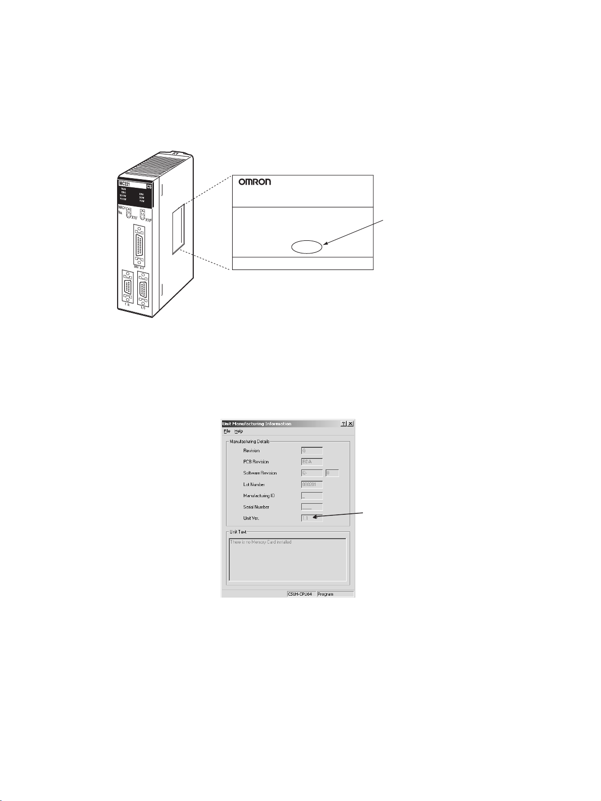
The unit version is given to the right of the lot number on the nameplate of the
products for which unit versions are being managed, as shown below.
Product nameplate
CS1W-MC221-V1
MC UNIT
Unit version
Example for unit version 1.1
Lot No. 080201 Ver.1.1
OMRON Corporation MADE IN JAPAN
The unit versions of Motion Control Units start with unit version 1.1.
CX-Programmer version 4.0 or higher can be used to confirm the unit version
using the Unit Manufacturing Information.
Manufacturing information.
2. The following Unit Manufacturing information Dialog Box will be displayed.
Unit version
xiii
Page 13

The unit version is displayed as 1.1 in the Unit Version Number field of the
above example. Use this display to confirm the unit version of the Motion Control Unit connected online.
Using the Unit Version
Label
A unit version label is provided with the Motion Control Unit. This label can be
attached to the front of the Motion Control Unit to differentiate between Motion
Control Units with different unit versions.
■ Unit Version Notation
Unit versions are given in this manual as shown in the following table.
Product label Notation in this manual Remarks
The version number is given
to the right of the lot number
for unit versions 1.1 and later,
e.g., “Ver. 1.1”
No version number is given to
the right of the lot number for
unit versions earlier than 1.1.
CS-series Motion Control Unit
with unit version 1.1 or later
Pre-Ver. 1.1 CS-series Motion
Control Unit
The contents of this
manual applies to all
unit version whenever the unit version
is not specified.
■ Functions Supported According to Unit Versions of Motion Control Units
Unit version Pre-Ver. 1.1 Units Units with unit
Internal system version Versions 1.01 to 3.01 Version 3.02
Absolute encoder functionality for
OMNUC G-series Servo Drivers
Not supported. Supported.
version 1.1
xiv
Page 14

Version Upgrade Information
Improvements from Pre-Ver. 1.1 to Version 1.1
The following improvements have been made.
Pre-Ver. 1.1 Ver. 1.1
The absolute encoder functionality for
OMNUC G-series Servo Drivers is not
supported.
The absolute encoder functionality for
OMNUC G-series Servo Drivers is supported.
xv
Page 15

xvi
Page 16

Read and Understand this Manual
Please read and understand this manual before using the product. Please consult your OMRON
representative if you have any questions or comments.
Warranty and Limitations of Liability
WARRANTY
OMRON's exclusive warranty is that the products are free from defects in materials and workmanship for a
period of one year (or other period if specified) from date of sale by OMRON.
OMRON MAKES NO WARRANTY OR REPRESENTATION, EXPRESS OR IMPLIED, REGARDING NONINFRINGEMENT, MERCHANTABILITY, OR FITNESS FOR PARTICULAR PURPOSE OF THE
PRODUCTS. ANY BUYER OR USER ACKNOWLEDGES THAT THE BUYER OR USER ALONE HAS
DETERMINED THAT THE PRODUCTS WILL SUITABLY MEET THE REQUIREMENTS OF THEIR
INTENDED USE. OMRON DISCLAIMS ALL OTHER WARRANTIES, EXPRESS OR IMPLIED.
LIMITATIONS OF LIABILITY
OMRON SHALL NOT BE RESPONSIBLE FOR SPECIAL, INDIRECT, OR CONSEQUENTIAL DAMAGES,
LOSS OF PROFITS OR COMMERCIAL LOSS IN ANY WAY CONNECTED WITH THE PRODUCTS,
WHETHER SUCH CLAIM IS BASED ON CONTRACT, WARRANTY, NEGLIGENCE, OR STRICT
LIABILITY.
In no event shall the responsibility of OMRON for any act exceed the individual price of the product on which
liability is asserted.
IN NO EVENT SHALL OMRON BE RESPONSIBLE FOR WARRANTY, REPAIR, OR OTHER CLAIMS
REGARDING THE PRODUCTS UNLESS OMRON'S ANALYSIS CONFIRMS THAT THE PRODUCTS
WERE PROPERLY HANDLED, STORED, INSTALLED, AND MAINTAINED AND NOT SUBJECT TO
CONTAMINATION, ABUSE, MISUSE, OR INAPPROPRIATE MODIFICATION OR REPAIR.
xvii
Page 17

Application Considerations
SUITABILITY FOR USE
OMRON shall not be responsible for conformity with any standards, codes, or regulations that apply to the
combination of products in the customer's application or use of the products.
At the customer's request, OMRON will provide applicable third party certification documents identifying
ratings and limitations of use that apply to the products. This information by itself is not sufficient for a
complete determination of the suitability of the products in combination with the end product, machine,
system, or other application or use.
The following are some examples of applications for which particular attention must be given. This is not
intended to be an exhaustive list of all possible uses of the products, nor is it intended to imply that the uses
listed may be suitable for the products:
• Outdoor use, uses involving potential chemical contamination or electrical interference, or conditions or
uses not described in this manual.
• Nuclear energy control systems, combustion systems, railroad systems, aviation systems, medical
equipment, amusement machines, vehicles, safety equipment, and installations subject to separate
industry or government regulations.
• Systems, machines, and equipment that could present a risk to life or property.
Please know and observe all prohibitions of use applicable to the products.
NEVER USE THE PRODUCTS FOR AN APPLICATION INVOLVING SERIOUS RISK TO LIFE OR
PROPERTY WITHOUT ENSURING THAT THE SYSTEM AS A WHOLE HAS BEEN DESIGNED TO
ADDRESS THE RISKS, AND THAT THE OMRON PRODUCTS ARE PROPERLY RATED AND INSTALLED
FOR THE INTENDED USE WITHIN THE OVERALL EQUIPMENT OR SYSTEM.
PROGRAMMABLE PRODUCTS
OMRON shall not be responsible for the user's programming of a programmable product, or any
consequence thereof.
xviii
Page 18

Disclaimers
CHANGE IN SPECIFICATIONS
Product specifications and accessories may be changed at any time based on improvements and other
reasons.
It is our practice to change model numbers when published ratings or features are changed, or when
significant construction changes are made. However, some specifications of the products may be changed
without any notice. When in doubt, special model numbers may be assigned to fix or establish key
specifications for your application on your request. Please consult with your OMRON representative at any
time to confirm actual specifications of purchased products.
DIMENSIONS AND WEIGHTS
Dimensions and weights are nominal and are not to be used for manufacturing purposes, even when
tolerances are shown.
PERFORMANCE DATA
Performance data given in this manual is provided as a guide for the user in determining suitability and does
not constitute a warranty. It may represent the result of OMRON's test conditions, and the users must
correlate it to actual application requirements. Actual performance is subject to the OMRON Warranty and
Limitations of Liability.
ERRORS AND OMISSIONS
The information in this manual has been carefully checked and is believed to be accurate; however, no
responsibility is assumed for clerical, typographical, or proofreading errors, or omissions.
xix
Page 19

xx
Page 20

PRECAUTIONS
This section provides general precautions for using the Motion Control Units (MC Units) and related devices.
The information contained in this section is important for the safe and reliable application of the Motion Control
Unit. You must read this section and understand the information contained before attempting to set up or operate
a Motion Control Unit.
1 Intended Audience . . . . . . . . . . . . . . . . . . . . . . . . . . . . . . . . . . . . . . . . . . . . . xxii
2 General Precautions . . . . . . . . . . . . . . . . . . . . . . . . . . . . . . . . . . . . . . . . . . . . xxii
3 Safety Precautions. . . . . . . . . . . . . . . . . . . . . . . . . . . . . . . . . . . . . . . . . . . . . . xxii
4 Operating Environment Precautions . . . . . . . . . . . . . . . . . . . . . . . . . . . . . . . . xxiii
5 Application Precautions . . . . . . . . . . . . . . . . . . . . . . . . . . . . . . . . . . . . . . . . . xxiv
6 Conformance to EC Directives . . . . . . . . . . . . . . . . . . . . . . . . . . . . . . . . . . . . xxvi
6-1 Applicable Directives . . . . . . . . . . . . . . . . . . . . . . . . . . . . . . . . . . . . xxvi
6-1-1 Concepts . . . . . . . . . . . . . . . . . . . . . . . . . . . . . . . . . . . . . . . . . . . . . . xxvi
6-1-2 Conformance to EC Directives . . . . . . . . . . . . . . . . . . . . . . . . . . . . . xxvi
xxi
Page 21

Intended Audience 1
1 Intended Audience
This manual is intended for the following personnel, who must also have
knowledge of electrical systems (an electrical engineer or the equivalent).
• Personnel in charge of installing FA systems.
• Personnel in charge of designing FA systems.
• Personnel in charge of managing FA systems and facilities.
2 General Precautions
The user must operate the product according to the performance specifications described in the operation manuals.
Before using the product under conditions which are not described in the
manual or applying the product to nuclear control systems, railroad systems,
aviation systems, vehicles, combustion systems, medical equipment, amusement machines, safety equipment, and other systems, machines, and equipment that may have a serious influence on lives and property if used
improperly, consult your OMRON representative.
Make sure that the ratings and performance characteristics of the product are
sufficient for the systems, machines, and equipment, and be sure to provide
the systems, machines, and equipment with double safety mechanisms.
This manual provides information for using the MC Unit. Be sure to read this
manual before attempting to use the Unit and keep this manual close at hand
for reference during operation.
!WARNING It is extreme important that Motion Control Units and related devices be used
for the specified purpose and under the specified conditions, especially in
applications that can directly or indirectly affect human life. You must consult
with your OMRON representative before applying Motion Control Units and
related devices to the above mentioned applications.
3 Safety Precautions
!WARNING Never attempt to disassemble any Units while power is being supplied. Doing
so may result in serious electrical shock or electrocution.
!WARNING Never touch any of the terminals while power is being supplied. Doing so may
result in serious electrical shock or electrocution.
!WARNING Provide safety measures in external circuits (i.e., not in the Programmable
Controller or MC Unit) to ensure safety in the system if an abnormality occurs
due to malfunction of the CPU Unit, malfunction of the MC Unit, or external
factors affecting the operation of the CPU Unit or MC Unit. Not providing sufficient safety measures may result in serious accidents.
• Emergency stop circuits, interlock circuits, limit circuits, and similar safety
measures must be provided in external control circuits.
• The CPU Unit will turn OFF all outputs when its self-diagnosis function
detects any error or when a severe failure alarm (FALS) instruction is executed. As a countermeasure for such errors, external safety measures
must be provided to ensure safety in the system.
xxii
Page 22

Operating Environment Precautions 4
• The CPU Unit or MC Unit outputs may remain ON or OFF due to deposits
on or burning of the output relays, or destruction of the output transistors.
As a countermeasure for such problems, external safety measures must
be provided to ensure safety in the system.
• When the 24-VDC output (service power supply to the CPU Unit) is overloaded or short-circuited, the voltage may drop and result in the outputs
being turned OFF. As a countermeasure for such problems, external
safety measures must be provided to ensure safety in the system.
!Caution Execute online edit only after confirming that no adverse effects will be
caused by extending the cycle time. Otherwise, the input signals may not be
readable.
!Caution Confirm the safety of the destination node before transferring a program to the
node or changing the contents of I/O memory. Doing either of these without
confirming safety may result in injury.
!Caution Connect the RUN command output (RUN signal) to the Servo Driver. Other-
wise, the motor may run when the power is turned ON or OFF or when en
error occurs in the Unit.
!Caution Do not save data into the flash memory during program execution or while the
motor is running. Otherwise, unexpected operation may be caused.
!Caution Do not reverse the polarity of the 24-V power supply. The polarity must be cor-
rect. Otherwise, the motor may start running unexpectedly and may not stop.
4 Operating Environment Precautions
!Caution Do not operate the control system in the following locations:
• Locations subject to direct sunlight.
• Locations subject to temperatures or humidity outside the range specified
in the specifications.
• Locations subject to condensation as the result of severe changes in temperature.
• Locations subject to corrosive or flammable gases.
• Locations subject to dust (especially iron dust) or salts.
• Locations subject to exposure to water, oil, or chemicals.
• Locations subject to shock or vibration.
!Caution Take appropriate and sufficient countermeasures when installing systems in
the following locations:
• Locations subject to static electricity or other forms of noise.
• Locations subject to strong electromagnetic fields.
• Locations subject to possible exposure to radioactivity.
• Locations close to power supplies.
xxiii
Page 23

Application Precautions 5
!Caution The operating environment of the PLC System can have a large effect on the
longevity and reliability of the system. Improper operating environments can
lead to malfunction, failure, and other unforeseeable problems with the PLC
System. Be sure that the operating environment is within the specified conditions at installation and remains within the specified conditions during the life
of the system.
5 Application Precautions
Observe the following precautions when using the MC Unit or the CPU Unit.
!WARNING Failure to abide by the following precautions could lead to serious or possibly
fatal injury. Always heed these precautions.
• Always ground the system to 100
protect against electrical shock.
• Always turn OFF the power supply to the Unit before attempting any of the
following. Not turning OFF the power supply may result in malfunction or
electric shock.
• Mounting or dismounting the MC Unit or any other Units.
• Assembling the Units.
• Setting rotary switches.
• Connecting cables or wiring the system.
• Connecting or disconnecting the connectors.
!Caution Failure to abide by the following precautions may lead to faulty operation of
the CPU Unit, the MC Unit. or the system, or could damage the CPU Unit or
MC Unit. Always heed these precautions.
• Check the task configuration before creating MC program for the MC Unit.
Set the task configuration (axis configuration, number of tasks, and task
axis definition) using the unit parameters within the system parameters. If
changes are made to the task configuration, the MC program must be
changed as well.
• After transferring the system parameters, G-language program, or position data to the MC Unit, be sure to save the data in flash memory within
the MC Unit (using the data save command from the CX-Motion or CPU
Unit) before turning OFF the power supply to the Unit. Transferring the
data to the MC Unit will simply save the data in the internal memory (SRAM) of the MC Unit and this data will be deleted when the power supply
to the Unit is turned OFF.
• After transferring the system parameter data to the MC Unit and saving
the data to flash memory, be sure to reset the power supply to the Unit or
restart the Unit. Otherwise, the unit parameters and machine parameters
will not be changed and the System Set Error, which can occur when the
system parameters are transferred to the MC Unit, will not be cleared.
• Do not turn OFF the power supply to the Unit while data is being written to
flash memory. Doing so may cause problems with the flash memory.
• Confirm that no adverse effects will occur in the system before changing
the operating mode of the Teaching Box.
• When a wiring error occurs, be sure to reset the power supply to the Unit,
check the wiring, and reset the machine parameters within the system
parameters.
Ω or less when installing the system to
xxiv
Page 24

Application Precautions 5
• Confirm that no adverse effect will occur in the system before attempting
any of the following. Not doing so may result in an unexpected operation.
• Changing the operating mode of the CPU Unit (including the setting of
the startup operating mode).
• Changing the present value of any word or any set value in memory.
• Force-setting/force-resetting any bit in memory.
• Install external breakers and take other safety measures against short-circuiting in external wiring. Insufficient safety measures against short-circuiting may result in burning.
• Be sure that all the mounting screws, terminal screws, and cable connector screws are tightened to the torque specified in this manual. Incorrect
tightening torque may result in malfunction.
• Tighten the mounting screws at the bottom of the Unit to a torque of
0.4 N • m. Incorrect tightening torque may result in malfunction.
• Before touching the Unit, be sure to first touch a grounded metallic object
in order to discharge any static built-up. Not doing so may result in malfunction or damage.
• Check the pin numbers before wiring the connectors.
• Be sure that the connectors, terminal blocks, I/O cables, cables between
drivers, and other items with locking devices are properly locked into
place. Improper locking may result in malfunction.
• Always use the power supply voltages specified in this manual. An incorrect voltage may result in malfunction or burning.
• Take appropriate measures to ensure that the specified power with the
rated voltage and frequency is supplied. Be particularly careful in places
where the power supply is unstable. An incorrect power supply may result
in malfunction.
• Use crimp terminals for wiring. Do not connect bare stranded wires
directly to terminals. Connection of bare stranded wires may result in
burning.
• Leave the label attached to the Unit when wiring. Removing the label may
result in malfunction if foreign matter enters the Unit.
• Remove the label after the completion of wiring to ensure proper heat dissipation. Leaving the label attached may result in malfunction.
• Do not apply voltages to the Input Units in excess of the rated input voltage. Excess voltages may result in burning.
• Do not apply voltages or connect loads to the Output Units in excess of
the maximum switching capacity. Excess voltage or loads may result in
burning.
• Separate the line ground terminal (LG) from the functional ground terminal (GR) on the Power Supply Unit before performing withstand voltage
tests or insulation resistance tests. Not doing so may result in burning.
• Double-check all wiring and switch settings before turning ON the power
supply. Incorrect wiring may result in burning.
• Do not pull on the cables or bend the cables beyond their natural limit.
Doing either of these may break the cables.
• Do not place objects on top of the cables or other wiring lines. Doing so
may break the cables.
• Resume operation only after transferring to the new MC Unit the contents
of the parameters, position data, and other data required for resuming
operation. Not doing so may result in an unexpected operation.
xxv
Page 25

Conformance to EC Directives 6
• Resume operation only after transferring to the new CPU Unit the contents of the DM Area, HR Area, and other data required for resuming
operation. Not doing so may result in an unexpected operation.
• Confirm that set parameters and data operate properly.
• Check the user program for proper execution before actually running it on
the Unit. Not checking the program may result in an unexpected operation.
• Do not attempt to take any Units apart, to repair any Units, or to modify
any Units in any way.
• Perform wiring according to specified procedures.
6 Conformance to EC Directives
6-1 Applicable Directives
•EMC Directives
• Low Voltage Directive
6-1-1 Concepts
EMC Directives
OMRON devices that comply with EC Directives also conform to the related
EMC standards so that they can be more easily built into other devices or
machines. The actual products have been checked for conformity to EMC
standards (see the following note). Whether the products conform to the standards in the system used by the customer, however, must be checked by the
customer.
EMC-related performance of the OMRON devices that comply with EC Directives will vary depending on the configuration, wiring, and other conditions of
the equipment or control panel in which the OMRON devices are installed.
The customer must, therefore, perform final checks to confirm that devices
and the overall machine conform to EMC standards.
Note Applicable EMC (Electromagnetic Compatibility) standards are as follows:
EMS (Electromagnetic Susceptibility): EN61131-2
EMI (Electromagnetic Interference): EN61000-6-4
Low Voltage Directive
Always ensure that devices operating at voltages of 50 to 1,000 VAC or 75 to
1,500 VDC meet the required safety standards for the PLC (EN61131-2).
6-1-2 Conformance to EC Directives
The CS-series PLCs comply with EC Directives. To ensure that the machine
or device in which a CS-series PLC is used complies with EC directives, the
PLC must be installed as follows:
1,2,3... 1. The PLC must be installed within a control panel.
2. Reinforced insulation or double insulation must be used for the DC power
supplies used for the communications and I/O power supplies.
3. PLCs complying with EC Directives also conform to the Common Emission
Standard (EN61000-6-4). When a PLC is built into a machine, however,
noise can be generated by switching devices using relay outputs and
cause the overall machine to fail to meet the Standards. If this occurs,
(Radiated emission: 10-m regulations)
xxvi
Page 26

Conformance to EC Directives 6
surge killers must be connected or other measures taken external to the
PLC.
The following methods represent typical methods for reducing noise, and
may not be sufficient in all cases. Required countermeasures will vary depending on the devices connected to the control panel, wiring, the configuration of the system, and other conditions.
xxvii
Page 27

Conformance to EC Directives 6
xxviii
Page 28

SECTION 1
Features and System Configuration
This section explains the features and system configuration of the CS1W-MC421 and CS1W-MC221 Motion Control Units
(MC Units), and outlines some of the differences with the features of the earlier C200H-MC221 MC Unit.
1-1 Features . . . . . . . . . . . . . . . . . . . . . . . . . . . . . . . . . . . . . . . . . . . . . . . . . . . . . . 2
1-1-1 Overview. . . . . . . . . . . . . . . . . . . . . . . . . . . . . . . . . . . . . . . . . . . . . . 2
1-1-2 Description of Features. . . . . . . . . . . . . . . . . . . . . . . . . . . . . . . . . . . 3
1-2 System Configuration . . . . . . . . . . . . . . . . . . . . . . . . . . . . . . . . . . . . . . . . . . . 4
1-2-1 System Configuration Example (CS1W-MC421) . . . . . . . . . . . . . . 4
1-3 Basic Operations . . . . . . . . . . . . . . . . . . . . . . . . . . . . . . . . . . . . . . . . . . . . . . . 7
1-3-1 Motion Control . . . . . . . . . . . . . . . . . . . . . . . . . . . . . . . . . . . . . . . . . 8
1-3-2 Other Functions . . . . . . . . . . . . . . . . . . . . . . . . . . . . . . . . . . . . . . . . 10
1-3-3 Summary of Function . . . . . . . . . . . . . . . . . . . . . . . . . . . . . . . . . . . . 11
1-4 Control System Configuration and Principles. . . . . . . . . . . . . . . . . . . . . . . . . 12
1-4-1 Servo System . . . . . . . . . . . . . . . . . . . . . . . . . . . . . . . . . . . . . . . . . . 12
1-4-2 Feedback Pulses . . . . . . . . . . . . . . . . . . . . . . . . . . . . . . . . . . . . . . . . 15
1-4-3 CW and CCW . . . . . . . . . . . . . . . . . . . . . . . . . . . . . . . . . . . . . . . . . . 15
1-5 Specifications . . . . . . . . . . . . . . . . . . . . . . . . . . . . . . . . . . . . . . . . . . . . . . . . . 16
1-5-1 Overview of Operations . . . . . . . . . . . . . . . . . . . . . . . . . . . . . . . . . . 21
1-5-2 Performance Chart . . . . . . . . . . . . . . . . . . . . . . . . . . . . . . . . . . . . . . 23
1-5-3 CX-Motion Functions . . . . . . . . . . . . . . . . . . . . . . . . . . . . . . . . . . . . 24
1-5-4 Teaching Box Functions . . . . . . . . . . . . . . . . . . . . . . . . . . . . . . . . . . 25
1-6 Data Exchange . . . . . . . . . . . . . . . . . . . . . . . . . . . . . . . . . . . . . . . . . . . . . . . . 26
1-6-1 Overall Structure. . . . . . . . . . . . . . . . . . . . . . . . . . . . . . . . . . . . . . . . 26
1-6-2 Explanation . . . . . . . . . . . . . . . . . . . . . . . . . . . . . . . . . . . . . . . . . . . . 27
1-6-3 Internal Block Diagram . . . . . . . . . . . . . . . . . . . . . . . . . . . . . . . . . . 28
1-6-4 Data Transfer Overview . . . . . . . . . . . . . . . . . . . . . . . . . . . . . . . . . . 29
1-7 Overview of G-language Programs in the MC Unit . . . . . . . . . . . . . . . . . . . . 30
1-7-1 Programs and Tasks . . . . . . . . . . . . . . . . . . . . . . . . . . . . . . . . . . . . . 30
1-7-2 Manual and Automatic Operation . . . . . . . . . . . . . . . . . . . . . . . . . . 32
1-7-3 G Language. . . . . . . . . . . . . . . . . . . . . . . . . . . . . . . . . . . . . . . . . . . . 33
1-7-4 G-language Codes. . . . . . . . . . . . . . . . . . . . . . . . . . . . . . . . . . . . . . . 35
1-8 Commands Listed According to Purpose . . . . . . . . . . . . . . . . . . . . . . . . . . . . 37
1-9 Comparison with Earlier MC Unit Model . . . . . . . . . . . . . . . . . . . . . . . . . . . 38
1-9-1 Changing From the C200H-MC221 to the CS1W-MC421/MC221 . 40
1-10 Basic Operating Procedure . . . . . . . . . . . . . . . . . . . . . . . . . . . . . . . . . . . . . . . 42
1-11 Methods for Using MC Unit Functions . . . . . . . . . . . . . . . . . . . . . . . . . . . . . 43
1-12 Overview of Version 1 Upgrades . . . . . . . . . . . . . . . . . . . . . . . . . . . . . . . . . . 45
1-12-1 Using Customized Functions . . . . . . . . . . . . . . . . . . . . . . . . . . . . . . 48
1-12-2 Easy Backup Function . . . . . . . . . . . . . . . . . . . . . . . . . . . . . . . . . . . 97
1
Page 29
Fe at ur e s Section 1-1
1-1 Features
1-1-1 Overview
The CS1W-MC421 and CS1W-MC221 are CS-series Motion Control Units
that can control four axes and two axes, respectively. With their internal G-language programming, they can be used for advanced motion control operations, such as traversing, and their multi-tasking capability allows operations
to be performed independently for each axis.
Two types of motion control are possible: point-to-point and continuous path.
Point-to-point Control With point-to-point (PTP) control, positioning is controlled independently for
each axis. The pathway varies according to the travel distances, the feed
rates, and so on, that are set.
Continuous Path Control With continuous path (CP) control, not only the start position and target posi-
tion can be controlled but also the path between those points. Linear interpolation, circular interpolation, helical circular interpolation, and traversing are all
possible.
The MC Unit has been developed for use in simple positioning applications
using servomotors. Applicable machines are as follows:
• Conveyor Systems: X/Y tables, palletizers/depalletizers, loaders/unloaders, etc. (Palletizers and depalletizers are devices used for loading goods
onto pallets or for unloading them from pallets. Loaders and unloaders
are devices that have shelves corresponding with the steps of a multistep
press and used for inserting or removing all the materials at one time.)
• Assembling Systems: Simple robots (including orthogonal robots), simple
automated assembling machines (such as coil winding, polishing, hole
punching), etc.
Note The MC Unit is not designed to perform linear interpolation, circular interpola-
tion, or helical circular interpolation with horizontal articulated robots or cylindrical robots, because it does not support coordinate conversions. The MC
Unit can, however, perform PTP control with these robots.
2
Page 30

Fe at ur e s Section 1-1
1-1-2 Description of Features
Multi-tasking G Language The MC Unit is provided with a multi-tasking G language, which is the opti-
mum language for motion control. The G language makes it simple to create
programs for multi-axis control, without placing a burden on the CPU Unit’s
ladder diagram program.
Simple and Fast Traverse
Operations
Fast Pick-and-place
Operations
Supports Absolute
Encoders
High-speed Response to
Start Commands from
CPU Unit
Two-axis MC Unit This function applies to the X axis when a 2-axis, 1-task configuration is used.
Four-axis MC Unit This function applies to the X axis when a 4-axis, 1-task configuration is used.
500-kp/s Encoder
Response Frequency
CPU Unit Interrupts A CPU Unit external interrupt task can be started by outputting a D code
Commands for 2-axis traverse operations enable simple and fast traverse
operations.
After a positioning command has been output, the in-position check OFF
function allows the next positioning operation to be started without waiting for
the first positioning operation to be completed. This makes it possible to perform high-speed pick-and-place operations.
The MC Unit is compatible with absolute encoders (such as the OMNUC W
Series) as a standard feature, eliminating the need to perform an origin
search. Incremental encoders can be used as well.
The response time from when a start command is received from the CPU Unit
until the command voltage is output from the MC Unit is 8 ms for two axes and
12 ms for four axes (MC421 only). This is 1.5 times faster than the previous
models.
The maximum feedback encoder response frequency is 500 kp/s, so the MC
Unit can be used with high-speed and high-precision servomotors. This is
double the response frequency of the earlier models.
(interrupt code) for the CPU Unit when positioning is completed or when passing through a particular position. This feature is ideal for high-speed synchronization between the MC Unit and CPU Unit.
Windows-based MC
Support Software
Data Creation Using
Teaching Box
Operate with MPG Positioning and simple sync operations can be performed using an MPG
Single-port Multi-access Function
A Windows-based Support Software package called CX-Motion can be used
on the same computer and through the same port as the CX-Programmer,
enabling multiple programming environments on a single computer.
Servo Information Trace Function
Speed reference values, the present speed, and the error counter can be
traced with specified starting conditions and a specified sampling period using
the MC Support Software. Up to 500 items can be traced, making it easy to
adjust the servo system.
Automatic Loading Function
When it is necessary to use more programs or position data than can be
stored in the MC Unit, programs or position data stored in an external memory
device at the computer where the MC Support Software is installed can be
automatically downloaded to the MC Unit’s internal memory.
In addition to entering numbers in the Position Data Edit Window of the MC
Support Software (CX-Motion), it is possible to create position data by using
the Teaching Box to teach positions while actually moving the machinery.
(manual pulse generator).
3
Page 31

System Configuration Section 1-2
F
E
D
C
B
A
9
8
7
6
5
4
3
2
1
0
F
E
D
C
B
A
9
8
7
6
5
4
3
2
1
0
Motor Driver Connection
Cables are provided for connecting to the motor driver.
Cables
1-2 System Configuration
The MC Unit receives control signals (CW limit, CCW limit, origin proximity,
and emergency stop input signals) from the Rack and control panel, and outputs command voltages to the servo driver.
1-2-1 System Configuration Example (CS1W-MC421)
Used for trial
operation,
debugging,
teaching, etc.
Teaching Box
Teaching Box
connector
SYSMAC
CS-series
PLC
I/O connector
• Monitoring (PV, I/O signals)
• Origin search
• Jogging
• Error reset
• Teaching
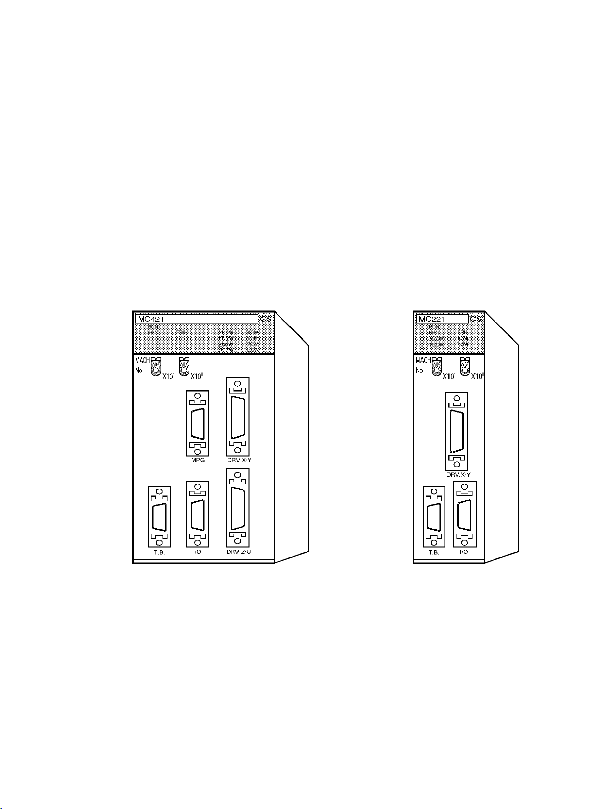
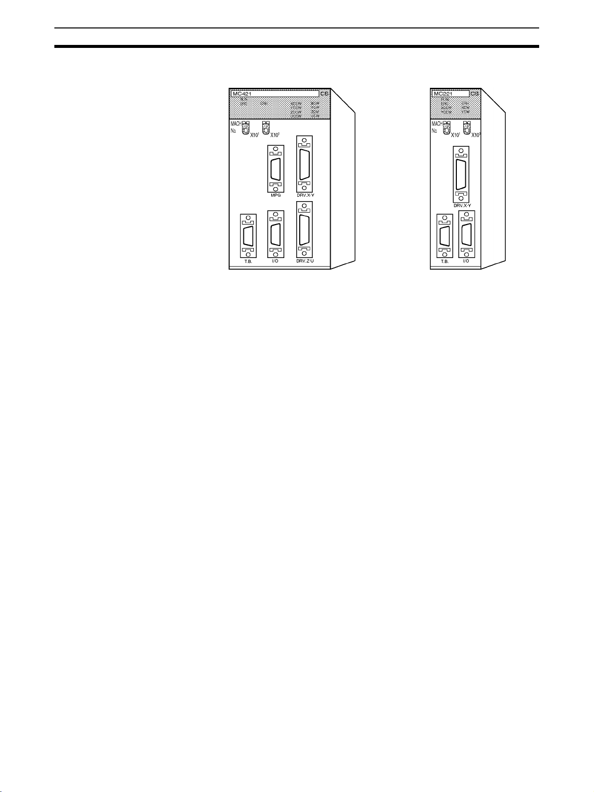
DRV X,Y connectors
MC
ERH
RUN
ERC
XCW
ZCW
XCCW
ZCCW
YCW
UCW
YCCW
UCCW
MACH
No.
1
0
X10
X10
WPC
DRV.X·Y
I/O
DRV.Z·U
TOOL
Terminal Block
(See note 2.)
MPG connector
Etc.
MC Unit
CPU Unit
Power Supply Unit
Peripheral port connector
RS-232C port
connector
DRV Z, U connectors
Driver Connection Cable (See note 1.)
Used for setting
data and programming in G
language.
• G language program editing
• Status monitoring
• File administration
Etc.
Personal computer
CX-Motion
CX-Programmer
External I/O
CCW limit input
CW limit input
Origin proximity input
Emergency stop input
One each for 4 axes
General-purpose inputs (4)
General-purpose outputs (4)
24-V power supply
for interface
ABS data backup battery (+2.8 V to +4.5 V) (See note 3.)
Servo driver
24-V power supply for interface
Either an absolute or incremental encoder
can be used.
Driver Connection Cable is available as an option for OMRON
H-, M-, U-, W-, and G-series
Servo Drivers.
MPG
MPG 1 channel
5-V power supply
for interface
Used when
precise positioning is required, as in
teaching.
•
Axis selection
•
Pulse ratio
selection
Etc.
4
Page 32

System Configuration Section 1-2
Note 1. A special Driver Connection Cable is available for OMRON U-, H-, M-,
W-, and G-series Servo Drivers. A cable can also be prepared by the user.
2. A special cable is available for connecting to a Terminal Block. The cable
can also be prepared by the user.
3. A data backup battery is required when using an absolute encoder.
The equipment and models used in this example system configuration are
shown in the following table.
Devices Model
Motion Control Unit CS1W-MC421/MC221
SYSMAC CS-series CPU
Unit
Power Supply Unit One of the following:
CPU Backplane CS1W-BC023/BC033/BC053/BC083/BC103
Teaching Box CVM1-PRO01 (Programming Console) + CVM1-MP702
Personal computer (for
CX-Motion and
CX-Programmer)
CX-Motion/CX-Programmer
Servo Driver R88D-M, -H, -U, -W, -G-series
Servomotor R88M-M, -H, -U, -W, -G-series
One of the following:
CS1H-CPU6@
CS1G-CPU4@
C200HW-PA204
C200HW-PA204S
C200HW-PA204R
C200HW-PA209R
C200HW-PD024
(ROM Cassette)
IBM PC/AT or compatible
CXONE-AL@@C-EV@/-AL@@D-EV@
Items Supplied by the
User
If you are using a manual pulse generator (MPG) in your system, prepare the
following items.
LGF-003-100 MPG (line driver output)
5-V power supply for the MPG
Sync encoders can also be connected to MPG connectors. Connecting a sync
encoder makes it possible, for example, to synchronize axis feeding with a
conveyer. If this is to be done, prepare the required sync encoder.
A data backup battery is required when using an absolute encoder. For
details, refer to the Servo Driver manual.
5
Page 33

System Configuration Section 1-2
In addition to the above, prepare power supplies for the Servo Driver interface
and for external I/O.
Power supply for the Servo Driver interface: 24 V
Power supply for the external I/O: 24 V
Cable to Connect CPU Unit to a IBM PC/AT or Compatible Running CX-Motion and CX-Programmer
Unit Port on Unit Port on
CPU Unit Peripheral 9-pin D-sub
RS-232C
(9-pin D-sub
female)
Serial Communications Board/
Unit
RS-232C
(9-pin D-sub
female)
computer
male
Serial
communications
mode (network)
Peripheral bus or
Host Link
Host Link XW2Z-200S-CV 2.0 m
Model numbers Length Remarks
CS1W-CN226 2.0 m --CS1W-CN626 6.0 m
XW2Z-200S-CV 2.0 m ESD (static
XW2Z-500S-CV 5.0 m
XW2Z-500S-CV 5.0 m
electricity)-resistant connectors
used.
Driver Connection Cable The Driver Connection Cable is a special cable for connecting the MC Unit to
the Servo Driver. It can be used for connecting OMRON H-, M-, U-, W-, and
G-series Servo Drivers.
I/O Cable and Terminal
Block
Connected Driver Cable model for 1
axis
R88D-H Series R88A-CPH001M1
R88A-CPH002M1
R88D-M Series R88A-CPM001M1
R88D-U Series (for
30-W to 750-W
Drivers)
R88D-U Series (for
1-KW to 5-KW
Drivers)
R88D-W Series R88A-CPW001M1
R88D-G Series R88A-CPG001M1
R88A-CPM002M1
R88A-CPU001M1
R88A-CPU002M1
R88A-CPUB001M1
R88A-CPUB002M1
R88A-CPW002M1
R88A-CPW003M1
R88A-CPW005M1
R88A-CPG002M1
R88A-CPG003M1
R88A-CPG005M1
The following table shows the model numbers of the I/O Cable and Terminal
Blocks for connecting CCW limit input signals, CW limit input signals, proxim-
Cable model for 2
axes
R88A-CPH001M2
R88A-CPH002M2
R88A-CPM001M2
R88A-CPM002M2
R88A-CPU001M2
R88A-CPU002M2
R88A-CPUB001M2
R88A-CPUB002M2
R88A-CPW001M2
R88A-CPW002M2
R88A-CPW003M2
R88A-CPW005M2
R88A-CPG001M2
R88A-CPG002M2
R88A-CPG003M2
R88A-CPG005M2
Length (m)
1.0
2.0
1.0
2.0
1.0
2.0
1.0
2.0
1.0
2.0
3.0
5.0
1.0
2.0
3.0
5.0
ity input signals, etc., to the MC Unit.
Name Model Remarks
MC Unit Terminal Block Connecting Cable
MC Unit Terminal Block XW2B-20J6-6 For CS1W-MC221 (2 axes)
XW2Z-100J-F1 Length: 1 m (for 2 or 4 axes)
XW2B-40J6-7 For CS1W-MC421 (4 axes)
6
Page 34

Basic Operations Section 1-3
1-3 Basic Operations
The MC Unit has been developed for use in simple positioning applications
using servomotors. Depending on the machine being controlled, the accuracy
of the MC Unit should be about five to ten times higher than the machine
being controlled. Applicable machines are as follows:
Conveyor Systems: X/Y tables, palletizers/depalletizers, loaders/unloaders,
etc.
Assembling Systems: Simple robots (including orthogonal robots), simple
automated assembling machines, etc.
Orthogonal Robots
One-axis robot Two-axis robot
Note The CS1W-MC221 can control one or two axes.
Horizontal Articulated Robots
Three-axis robot Four-axis robot
PTP control can be performed when horizontal articulated robots or cylindrical
robots are used, but linear interpolation, circular interpolation, and helical circular interpolation are not possible.
Two-axis robot
Three-axis robot
X: Although point-to-point control is
possible, linear and circular
interpolation are not possible for
the ends of the robot arms.
Four-axis robot
7
Page 35

Basic Operations Section 1-3
Cylindrical Robots
Two-axis robot
X: Although point-to-point control is
possible, linear and circular
interpolation are not possible for
the ends of the robot arms.
Four-axis robot
Three-axis robot
1-3-1 Motion Control
The MC Unit offers the following three types of motion control:
PTP Control
CP Control (linear interpolation and circular interpolation)
Interrupt Feeding
Control programs are created in the G language.
PTP Control PTP control is used to control each axis (X and Y axis) independently. Posi-
tioning time depends on the travel distance and speed of each axis.
Example: Moving from the origin to the X-axis coordinate of 100 and Y-axis
coordinate of 50 at the same speed.
Positioning is executed separately for each
axis, so travel between the two points is
carried out as shown in the diagram.
8
Page 36

Basic Operations Section 1-3
CP Control CP control is used to position by designating not only the starting point and
the target point, but also the path between these two points. Both linear interpolation and circular interpolation are possible.
Circular
interpolation
Target point
Linear interpolation
Starting point
Interrupt Feeding Interrupt feeding is used to perform speed control until an external signal is
input and to perform position control for a fixed distance when the external
signal is input. Positioning with no interrupt signal is also possible.
Multiturn Circular
Interpolation
Speed
Speed control Position control
Signal input
(fixed distance)
The multiturn circular interpolation function has been added to the existing circular and helical circular interpolation functions. This function can be used for
applications such as winding machine operations.
Central axis Z
End point (target position)
Movement in direction of central axis
Feed
pitch
Beginning point
(present position)
9
Page 37

Basic Operations Section 1-3
Traversing
The following illustration shows the action of the winder (traverse function) for
a winding machine.
Winder
Traverse axis
Unlimited Feeding This function executes unlimited feeding for the specified axis.
1-3-2 Other Functions
Origin Search Establishes the origin for a specified axis.
Jogging Starts and stops positioning at a specified speed along a specified axis.
Error Counter Reset Forcibly resets the error counter to zero and stops axis operation after a
deceleration command.
Present Position Preset Changes the present position according to specified position data.
Teaching Obtains the present position to create position data.
Zones A Zone Flag turns ON when the present position is within a preset range.
Override (Real Time
Speed Change)
Backlash Correction Compensates for inaccurate meshing in the mechanical system.
Electronic Gears Sets a pulse ratio for the input pulses with MPG/sync encoders.
Changes the speed during PTP, linear interpolation, or circular interpolation
operations.
10
Page 38

Basic Operations Section 1-3
1-3-3 Summary of Function
The following diagram summarizes the MC Unit functions.
Stop Mode
MC Unit functions
Automatic Mode
(Executes G-language programs
in the MC Unit.)
Manual Mode
(Executes manual commands
from the CPU Unit or Teaching
Box.)
Common to Automatic
and Manual Modes
Position control
Speed control
Origin search
Interrupt feeding
Traversing
Arithmetic operations, etc.
Deceleration stop
Origin search (manual)
Standard origin return
Jogging
Error counter reset
Forced origin
Absolute origin setting
Servo lock/Servo unlock
Present position preset
Teaching
Zones
Backlash correction
Override
Electronic gear
Pass Mode
In-position
Check OFF Mode
Dwell timer
Note Positioning operations using the MC Unit are performed based on two coordi-
nate systems: A reference coordinate system and a workpiece coordinate
system.
The reference coordinate system is the most fundamental one for positioning
operations. The workpiece coordinate system is offset from the reference
coordinate system by a specified amount, allowing the user to freely set a
coordinate system.
Offset of the
workpiece
coordinate
system
Workpiece
coordinate
system
Offset of the workpiece
Reference
coordinate
system
coordinate system
11
Page 39

Control System Configuration and Principles Section 1-4
1-4 Control System Configuration and Principles
1-4-1 Servo System
The servo system used by and the internal operations of the MC Unit are
briefly described below.
Semi-closed Loop System The servo system of the MC Unit uses a semi-closed loop system. This sys-
tem is designed to detect actual machine movements by rotation of the motor
in relation to a target value. It computes the error between the target value
and actual movement, and zeroes the error through feedback.
Ta bl e
Servomotor
Encoder
Actual
movement
Ball screw
Decelerator
Target value
Semi-closed loop systems occupy the mainstream in modern servo systems
applied to positioning devices for industrial applications.
Position controller
Internal Operations of the
MC Unit
1,2,3... 1. The error counter receives a target position in units of encoder pulses. This
Commands to the MC Unit, speed control voltage to the servo driver, and the
feedback signals from the encoder are described in the next few pages.
Speed
control
voltage
Desired position
Pulse string
Error
counter
D/A
converter
Position feedback
Feedback pulses
Servo driver Servomotor
Speed
feedback
Encoder
is called a pulse string.
2. The error counter is directly connected to the D/A converter where the
pulses received by the error counter are converted to analog voltages.
These analog voltages are sent to the servo driver as the speed control
voltages.
12
Page 40

Control System Configuration and Principles Section 1-4
3. When the speed control voltage is received by the servo driver, it rotates
the motor at a speed corresponding to the speed control voltage. The rotational speed is in proportion to the speed control voltage.
Servo Driver Speed Characteristics
Rotational speed +N (r/min)
Speed control voltage
4. The rotary encoder directly connected to the motor axis rotates in sync
with the motor and generates feedback pulses.
5. The error counter is reduced by the feedback pulses until the error counter
goes to zero. When the error counter goes to zero, the speed control voltage to the servo driver becomes zero and the motor stops rotating.
Target position value
(pulses)
Error counter count
(pulses)
Speed control voltage
Time
Time
Positioning end
Time
13
Page 41

Control System Configuration and Principles Section 1-4
6. Unless the target position is given, the error counter constantly maintains
the stopped position.
7. If the motor axis moves slightly due to a drift in the driver or voltage output,
the error counter receives a feedback pulse from the rotary encoder and a
speed control voltage is output in the reverse direction, causing the motor
to rotate toward its original position. This corrective operation for maintaining the present position is called servolock or servoclamp.
8. Using this principle, positioning with acceleration and deceleration is executed by continuously setting target positions in the error counter.
9. The target position set in the error counter becomes the error counter
count as shown below. The count is converted to a speed control voltage
for the servo driver to control the motor.
Target position value
(pulses)
Time
Error counter count
(pulses)
Time
Speed control voltage
Time
Thus, the position equals the total count of target positions (shaded area in
the figure), and the speed will depend on the target position value per unit
time.
14
Page 42

Control System Configuration and Principles Section 1-4
1-4-2 Feedback Pulses
Standard OMRON Servomotors are designed for an advanced phase-A for
forward rotation and an advanced phase-B for reverse rotation. The MC Unit
is designed to comply with this phase advancement, allowing OMRON Driver
Connecting Cables to be connected without modification.
Forward Rotation (Positive Speed Reference)
Phase A
Phase B
Reverse Rotation (Negative Speed Reference)
Phase A
Phase B
When using Servomotors by other manufacturers, check carefully the encoder
specifications. If the definition differs from the ones given above, take one of
the following actions:
• Reverse the phase-B wiring between the MC Unit and the servo driver.
(Reverse the +B terminal and the –B terminal.)
• Set the machine parameter “encoder polarity” in the system parameters
to “reverse rotation for encoder increase.” It is initially set to the “forward
rotation at the encoder increase.”
1-4-3 CW and CCW
The abbreviations “CW” and “CCW” used in this manual to describe the operation of the MC Unit are defined as follows:
CW (Clockwise) Clockwise is the direction in which the present position increases.
CW
Negative limit
CCW (Counterclockwise) Counterclockwise is the direction in which the present position decreases.
Positive limit
Negative limit
CCW
Positive limit
15
Page 43

Specifications Section 1-5
1-5 Specifications
General Specifications
Item Specifications
Model CS1W-MC221 CS1W-MC421
Power supply
voltage
Voltage fluctuation
tolerance
Internal current
consumption
Weight (Connectors excluded)
Safety standards Conforms to UL (Class 2), CSA (class 2), and EC specifica-
External
dimensions
Specifications other than those shown above conform to those for the
SYSMAC CS Series.
5 VDC (from Backplane)
24 VDC (from external power supply)
4.75-5.25 VDC (from Backplane)
21.6-26.4 VDC (from external power supply)
600 mA or less for 5 VDC (with
Teaching Box connected:
800 mA or less)
0.2 A or less for 24 VDC
450 g max. 540 g max.
tions.
130.0 x 35.0 x 100.5 mm
(H x W x D)
700 mA or less for 5 VDC (with
Teaching Box connected:
1,000 mA or less)
130.0 x 70.0 x 100.5 mm
(H x W x D)
Functions and Performance Specifications
Item Specifications
Applicable PLC CS Series
Type of Unit CS Special I/O Unit
Backplanes on which MC Unit can
be mounted
Method for data
transfer with
CPU Unit
Controlled Driver Analog input servo driver (Example: OMRON OMNUC H, M, U,
Built-in program language G language (Started by receiving a start command from the CPU
Control Control method Speed reference voltage output-type semi-closed loop system,
Words allocated
to Special I/O
Units in CIO Area
Words allocated
to Special I/O
Units in DM Area
Number of
controlled axes
CS1W-MC221 CS1W-MC421
CPU Backplane or CS Expansion I/O Backplane (See note 1.)
30 words/Unit (uses 3 unit
numbers.) (See note 2.)
CPU Unit to MC Unit:
Commands: G-language program execution/stop, origin search,
manual operation, etc.
Data transfer: Position data, acceleration/ deceleration data, etc.
MC Unit to CPU Unit:
Status: Positioning completed, zones, busy flag, etc.
Monitor data: Present position, error codes, M codes, etc.
Not used. Not used.
W, or G Series)
Unit ladder diagram program.)
using incremental and absolute encoder inputs.
2 max. 4 max.
Multitasking can be used to execute independent operating
modes and programs for each axis.
50 words/Unit (uses 5 unit
numbers.) (See note 2.)
16
Page 44

Specifications Section 1-5
Item Specifications
CS1W-MC221 CS1W-MC421
Automatic/Manual Mode (for each
task)
Encoder interface Line receiver input; maximum response frequency: 500 kp/s
Control unit Minimum setting
unit
Units mm, inch, degree, pulse (There is no unit conversion function.)
Maximum command value –39,999,999 to +39,999,999
Number of controlled axes 2 axes max. 4 axes max.
Positioning
operations
Speed reference 1 pps to 2,000 kp/s (when ratio is 4)
Acceleration/deceleration curve Trapezoidal or S-curve
Acceleration/deceleration time Individual acceleration/deceleration settings possible: 0 to
PTP (independent) control
Linear interpolation
Circular interpolation
Helical circular
interpolation
Traverse function Traverse operation for two axes
Speed control Speed control for each axis
Unlimited Feed
Mode
Interrupt feeding Feeding a fixed distance after an interrupt input, for each axis.
Automatic Mode: Mode for executing MC program created in G
language.
Manual Mode: Mode for executing manual commands from CPU
Unit (PLC interface area) or Teaching Box.
• The Automatic or Manual Mode is set according to the PLC
interface area of the CPU Unit.
• There are a total of 11 Automatic Mode commands, including
origin search, reference origin return, JOG, and error reset.
• The operation cycle is started in Automatic Mode through dedicated bits in the CPU Unit or from the Teaching Box.
(before multiplication)
Pulse ratio: Select 1, 2, or 4
Note: The applicable absolute encoders are the OMRON
OMNUC U-, W-, and G-series Encoders.
A Motion Control Unit with unit version 1.1 or later is
required to use the absolute encoder functionality of the
OMNUC G Series.
1, 0.1, 0.01, 0.001, 0.0001
See note 3.
(When the minimum setting unit is 1.) (See note 6.)
Execution by independent programs, operating modes for each
axis.
2 axes max. 4 axes max.
Circular interpolation for a maximum of two axes on a plane.
--- Circular interpolation for a max-
imum of two axes on a plane +
one axis for feed control
Axis feeding can be executed with no limit.
(Positioning with no interrupt input signals is also possible.)
100,000 ms (2-ms increments)
17
Page 45

Specifications Section 1-5
Item Specifications
CS1W-MC221 CS1W-MC421
External I/O Peripheral device Teaching Box (1 only)
Encoder Line receiver inputs:
MPG /sync
encoder
Servo driver
relationships
Individual axis
control (See note
4.)
Others (See note
4.)
Feed operations High-speed feed
rate
Interpolation feed
rate
High-speed feed
override
Interpolation feed
override
Jog feed override 0.1% to 100.0% (Setting unit: 0.1%)
Axis control Zone settings Up to 8 zones/axis can be set.
Backlash
correction
In-position zone Can be set from 0 to 10,000 pulses.
Position loop gain 1 to 250 (1/s)
Feedforward gain 0% to 100%
For two axes
(500 kp/s before multiplication)
Line driver output-type MPG/sync encoder: 1
500 kp/s max. (before multiplication)
The following signals are each
provided for two axes:
Inputs: Driver alarm signals
Outputs: Driver alarm reset signals
High-speed reference voltage outputs (±10 V)
Operation command outputs
SEN signals (for absolute encoder)
The following signals are each
provided for two axes:
Input: CCW limit inputs
CW limit inputs
Origin proximity inputs
Emergency stop inputs
General inputs: 4 pts. (interrupt inputs)
General outputs: 4 pts. (brake signal outputs)
Example: 36.86 m/min
Conditions
Encoder resolution: 2,048 p/r
Motor speed: 4,500 r/m
Control unit: 0.001 mm/pulse
0.1% to 100.0% (Setting unit: 0.1%)
0.1% to 199.9% (Setting unit: 0.1%)
Can be set from 0 to 10,000 pulses.
Line receiver inputs:
For four axes
(500 kp/s before multiplication)
The following signals are each
provided for four axes:
The following signals are each
provided for four axes:
18
Page 46

Specifications Section 1-5
Item Specifications
CS1W-MC221 CS1W-MC421
Task program
management
Saving program
data
Program and position data
automatic download function
Self-diagnostic function Memory corruption is detected.
Error detection functions Error counter warning, error counter over, absolute encoder error
Error log function Stores up to 20 error log records.
Number of tasks 2 max. (program execution
Number of
programs
Program capacity When 1 task is used:
Position data
capacity
Number of
registers
Subroutine
nesting
MC Unit Backed up by flash memory. (See note 5.)
External
peripheral devices
units)
The maximum number of
programs differs according to
the number of tasks.
When 1 task is used: 100
When 2 tasks are used: 50
2,000 blocks
When 2 tasks are used:
1,000 blocks/task
The maximum number of
blocks in a single program is
800.
2,000 positions max. (total for all axes)
32 (Mainly used for specifying position data numbers.)
5 levels max.
CX-Motion can be used to save data to a floppy disk or the hard
disk at the personal computer.
When the operation number (program or position data) is
specified by an IOWR instruction from the CPU Unit, CX-Motion
recognizes it and downloads the program or position data to the
MC Unit.
detection, CPU errors, communications errors (Teaching Box),
flash memory error, EEPROM error, software limit over error,
phase-Z error, overtravel, emergency stop, unit number error,
driver alarm detection, driver reverse wiring detection, CPU Unit
error detection
4 max. (program execution
units)
The maximum number of
programs differs according to
the number of tasks.
When 1 task is used: 100
When 2 tasks are used: 50
When 3 task are used: 33
When 4 tasks are used: 25
When 1 task is used:
When 2 tasks are used:
When 3 task are used:
When 4 tasks are used:
The maximum number of
blocks in a single program is
800.
2,000 blocks
1,000 blocks/task
666 blocks/task
500 blocks/task
Note 1. The MC Unit must be mounted to the CPU Rack to use D codes. D codes
will not be sent to the CPU Unit if the MC Unit is mounted to a CS Expansion Rack.
2. The number of MC Units that can be mounted under one CPU Unit must
be determined based on the maximum number of Special I/O Units that
can be allocated words in the CPU Unit, the power supply capacity on the
CPU or Expansion Rack, and the current consumption of the Units mounted to the Rack. Refer to the CPU Unit’s operation manual for details on calculation methods.
3. To display units other than pulses in the CX-Motion, change the display unit
and then set the Pulse Rate to the amount of workpiece movement per
pulse.
4. The required power supply must be provided by the user.
5. The service life for the flash memory is 100,000 writing operations.
19
Page 47

Specifications Section 1-5
6. The maximum position command values, software limit values, and zone
values are as shown in the following table for each minimum setting unit.
Minimum setting unit
1 0.1 0.01 0.001 0.0001
–39999999 to
+39999999
The actual maximum ranges that can be set may be smaller than those
shown above depending on the pulse rate. The maximum set value must
satisfy the following two conditions:
•|Set value (C)|
•|Set value (C)|
P: Pulse rate (Pulse/pulse, mm/pulse, degrees/pulse, and inch/pulse)
C: Minimum setting unit (1, 0.1, 0.01, 0.001, 0.0001)
Example: If the minimum setting unit is 0.01 and pulse rate is 0.0001, the
maximum set value can be calculated as follows:
1073741823 x 0.0001=10734.1823 < 399999.99
Therefore, the maximum range is –10734.18 to 10734.18 (because the
minimum setting unit is 0.01).
Also, the maximum present position shown by CX-Motion or the Teaching
Box will be within the ranges indicated in the table above.
–3999999.9 to
+3999999.9
≤ 1073741823 x P
≤ 39999999 (C)
–399999.99 to
+399999.99
–39999.999 to
+39999.999
–3999.9999 to
+3999.9999
Demand Positions and
Present Positions
Range of position data (mm) that can be
transferred between the MC Unit and other
devices (Teaching Box, CX-Motion, and CPU
Unit)
Position data (pulses)
handled inside the MC Unit
Data is stored internally in the MC Unit for the demand positions, software limits, present positions, zones, reference origin offsets, and workpiece origin offsets as 32-bit signed data in pulse units. The Teaching Box, CX-Motion, and
CPU Unit, however, handle data in millimeters within the ranges described in
note 2 for the above table. Depending on the pulse rate setting, the axes may
move or stop in positions that cannot be handled by these devices. If a position is beyond the range that can be handled by these devices, it will be indicated as the maximum (399,999,999) or minimum (–399,999,999) value until
the position returns within the range that can be indicated.
Pulse rate
conversion
The position will
be indicated as
−39,999,999 in
this range.
The position will be transferred
and updated in this range.
Pulse rate
conversion
The position will
be indicated as
39,999,999 in this
range.
20
Note 1. The present position data held inside the MC Unit (32-bit signed data) can
be directly read by the CPU Unit using the IORD instruction. Use addresses 17BA hex, 17BB hex, 17BC hex, and 17BD hex.
2. The present position monitoring function of the CX-Motion can be used to
display the reference coordinate system present value in pulses between
–268,435,455 and 268,435,455 (28-bit data).
Page 48

Specifications Section 1-5
1-5-1 Overview of Operations
Item Contents
Operating modes Manual Mode: Operation according to CPU Unit
Manual Jogging Moves axes continuously by manual operation.
Handle feed Moves axes by MPG.
Deceleration stop Decelerates to a stop according to command.
Manual origin search Searches for mechanical origin. (Origin search is
Manual origin return Moves to origin in reference coordinate system.
Forced origin Forcibly sets the present position to 0 to establish
Absolute origin setting Sets the origin for an absolute encoder.
Servo-lock Creates a position loop and turns ON the
Servo-unlock Releases the position loop and applies the brake,
Electronic gear function A fixed ratio (numerator and denominator) can be
memory area or commands from Teaching Box.
Automatic Mode: Operation according to com-
mands in G-language program.
possible in either an incremental or absolute
encoder system.)
it as the origin. (In an absolute encoder system,
only the present position of the MC Unit will be
set to 0.)
operation command output to the servo driver,
while simultaneously releasing the brake. When
an absolute encoder is used, the absolute
position is read before the servo-lock is applied.
and simultaneously turns OFF the operation
command output to the servo driver.
Servo-unlock can be executed even in Automatic
Mode.
applied to input pulses, and output to the
servomotor driver.
21
Page 49

Specifications Section 1-5
Item Contents
Automatic Positioning with linear interpolation Executes linear interpolation at the specified
Positioning with circular interpolation Executes clockwise or counterclockwise 2-axis
Positioning with helical circular
interpolation
Traverse function Executes winding (traverse operation).
Speed control Moves a maximum of either two or four axes at a
Interrupt feeding Moves a specified axis for a fixed amount when a
Switching to Pass Mode Changes to Pass Mode, in which operations are
Switching to In-position Check OFF
Mode
Stop-over function Outputs an M code or a D code while axes are
Dwell timer Pauses positioning for a specified time.
Workpiece origin return Automatically returns to workpiece origin.
Automatic origin return Automatically returns to reference coordinate
Automatic Cycle start Executes a specified program from the first block,
Single block Executes the program one block at a time.
Pause Temporarily halts program execution.
Forced block end Forcibly ends execution of a block.
Error reset Clears error status.
M code reset Resets the M code (for interlock).
Teaching Creates position data for each task.
Auxiliary Optional inputs 20 points: Specify input information to be
M code 0 to 999
D code (interrupt
code)
interpolation feed rate for up to either two or four
axes simultaneously.
circular interpolation at the specified interpolation
feed rate.
Executes clockwise or counterclockwise 2-axis
circular interpolation and 1-axis linear
interpolation (i.e., helical interpolation) at the
specified interpolation feed rate. (Available for
CS1W-MC421 only.)
controlled speed.
general input is turned ON. With interrupt feeding,
positioning without an interrupt signal can be
executed.
executed one by one with no deceleration stop. In
Pass Mode, the interpolation acceleration or
deceleration time of the previous operation can
be specified for the next operation (Pass Mode
time selection). A pass operation for only one axis
can be executed at a fixed acceleration (with a
fixed acceleration mode setting).
Starts the next positioning operation without
waiting for the current one to be completed.
being moved by a fixed amount (determined by
present position), without stopping the operation.
G codes are also possible for all operations.
system origin.
or resumes execution of a stopped program.
referenced by special G code.
Of the 20 input points, 4 can be specified as
general-purpose inputs for the MC Unit.
0 to 499: M code for taking interlock
500 to 999: M code not taking interlock
0 to 255
Starts a CPU Unit external interrupt task when
positioning is completed or when passing through
a particular position.
22
Page 50

Specifications Section 1-5
Item Contents
Automatic
and Manual
Mode
Backlash correction The amount of correction for backlash in the
Error counter reset Forcibly resets the error counter to 0, and stops
Override Changes the operating speed by applying a
Zones A zone flag turns ON when the present position
Unlimited Feed Mode, unlimited
present position display
Origin search function The search pattern can be selected to shorten
Trapezoid/S-curve acceleration and
deceleration
Driver alarm reset Resets the servo driver alarm.
Data transfer Data is transferred between the CPU Unit and the
Servo data trace function Up to 500 data items, including speed reference
mechanical system can be registered in advance.
axis operation. (Enabled when no speed
reference is provided to the servo driver.)
specified percentage to the speed specified in the
system parameters or G-language program.
enters a preset range.
Moves the axis with no limit. In this mode, a range
for refreshing the present position can be specified.
the origin search time. Either a deceleration stop
or accumulated pulse stop can be selected for
when a limit input is received during the origin
search.
Either trapezoid or S-curve acceleration and
deceleration can be specified for starting and
stopping each axis.
MC Unit by means of the CPU Unit’s IORD and
IOWR instructions. There are two modes for
transferring data: One for transferring large
amounts of data, and another for rapidly
transferring small amounts of data.
values, present speed, and error counter data,
can be traced for each axis. This data can be
referenced by CX-Motion.
1-5-2 Performance Chart
Item Typical value Description
Power ON startup time Average: 600 ms Time from turning ON the power until
Cyclic service time MC221: 0.8 ms/Unit
IOWR execution time 0.7 ms/instruction Time by which the cycle time will be
IORD execution time 0.8 ms/instruction Time by which the cycle time will be
Data write time 475 ms/1,000 words Time from when IOWR is executed
Data read time 470 ms/1,000 words Time from when IORD is executed
Operation startup time MC221: 8 ms
Analog voltage output
time lag per axis for
interpolation
Analog voltage output
time lag per axis for
independent operation
MC421: 0.85 ms/Unit
MC421: 12 ms
MC221: 150 µs
MC421: 210 µs
MC221: 4.3 ms/axis
MC421: 4.3 ms/axis
manual operation commands are
accepted.
Time by which the CPU Unit cycle
time will be extended per MC Unit.
extended when IOWR is executed.
extended when IORD is executed.
until data transfer is completed.
until data transfer is completed.
MC221: Time for X axis operation
with a 1-task, 2-axis configuration.
MC421: Time for X axis operation
with a 1-task, 4-axis configuration.
Time delay when interpolation is
performed for 1 task.
Time delay when one axis each is
started for all tasks simultaneously.
23
Page 51

Specifications Section 1-5
Item Typical value Description
Interrupt notification time 2.25 ms When C200H@-series Special I/O
G language
interpretation time
Minimum operation time MC221: 8.5 ms
Minimum traverse
reversal time
External input response
time
Zone Flag notification
time
MC221: 2.0 ms
MC421: 4.2 ms
MC421: 9.5 ms
2 ms Reversing operation is possible
General purpose input: 4.5 ms max.
Emergency stop input: 4.5 ms max.
CW/CCW limit input: 4.5 ms max.
Origin proximity input: 4.5 ms
MC221: 14.08 ms
MC421: 34.08 ms
Unit is not mounted.
Interpretation time for G language
when axis movement is not
performed.
When the time for linear interpolation
is equal to or less than the values
given, Stop Mode operation will be
used even in Pass Mode or
In-Position Check OFF Mode.
every 2 ms for traverse operation.
Response time to external input
signals.
The time required for one Zone Flag
to respond.
Note The above typical values will change depending on the task and axis configu-
ration.
1-5-3 CX-Motion Functions
Function Explanation
Program editing Creating, changing, and clearing MC programs.
Position data editing Creating, changing, and clearing position data.
Parameter editing Creating and changing system parameters, and
clearing to defaults.
Transfer and comparison Transferring and verifying MC programs, system parameters, and position
data contents between MC Unit and personal computer.
Printing Printing MC programs, system parameters, and position data contents.
Monitoring Monitoring MC programs that are being run.
Monitoring present values:
Reference coordinate system PV (user settings and pulses)
Workpiece coordinate system PV
Workpiece origin shift amount
Error counter value
MC Unit FAL status
MC Unit I/O status
MC Unit error log (CS1W-MC421/MC221 only)
File management File list display, loading, saving, changing
User-defined mnemonics Setting G code by mnemonics.
Servo trace Displaying servo trace data with the MC Unit
Automatic loading Automatic downloading of programs and position data to the MC Unit
File conversion Converting parameters created by MC Support
(CS1W-MC421/MC221 only).
(CS1W-MC421/MC221 only).
Software for use by the CS1W-MC421/MC221.
24
CX-Motion can be installed from the CX-One. Refer to the CX-One Setup
Manual (Cat. No. W463) for information on system requirements and installa-
tion methods for the CX-One.
Page 52

Specifications Section 1-5
1-5-4 Teaching Box Functions
Function Description
Deceleration stop Decelerates all axes to a stop and stops the execution of a program.
Error reset MC Unit error reset Resets errors that have occurred in the MC Unit.
Servo driver error
reset
Monitoring Present values Monitors the following present values:
Position data Reads, changes, and creates position data stored in the MC Unit.
Errors Reads errors that have occurred in the MC Unit.
I/O signals Monitors and changes I/O signals connected to the MC Unit.
Phase-Z margin Monitors the number of pulses to phase Z from the origin input.
Servo parameters Reads and changes servo parameters.
Origin search Searches for the origin.
Program execution Task/program No.
designation
Cycle run Executes tasks.
Single block run Executes the program block by block.
Jogging Jogs individual axes. More than one axis cannot be jogged at the same
MPG feeding Pulse ratio Designates the ratio for 1 pulse for the MPG.
Override Increases or decreases the operating speed during program execution.
Teaching Registers the present position as position data.
Extension Mode Changes the mode used to control the MC Unit.
Servo-lock/
servo-unlock
Memory protection Protects or clears protection for the memory (position data area, system
Absolute origin setting Sets the absolute encoder’s mechanical origin to 0, and establishes it as
Teaching Box
message display
Saving Stores system parameters, position data, and programs in the flash
Error detection CPU errors
Resets alarms for the servo driver.
Present position in the reference coordinate system (using user-set
unit such as mm).
Present position in the reference coordinate system (in pulses).
Error counter value.
Designates the desired task and program to be executed.
time.
Locks or releases the servomotor.
parameters) in the MC Unit.
the origin.
Executed when first using a absolute encoder or after replacing the
absolute encoder.
Switches between English and Japanese for the Teaching Box message
display.
memory.
Communications errors
25
Page 53

Data Exchange Section 1-6
1-6 Data Exchange
The CPU Unit Controls the MC Unit through the PLC interface area in the
CPU Unit during I/O refreshing and by data inputs and outputs at a any time.
1-6-1 Overall Structure
CPU Unit
PLC Interface Area
n
Operation-related commands
:
• Program number designation
:
• Automatic/manual
:
• Cycle star t
:
• M code reset
:
PLC interface area
• Jog operation
(10 or 18 words)
n+17 (n+9)
n+18 (n+10)
n+47 (n+25)
Status input
:
• Error classification data
:
• System status
:
• Error code
:
• M code
:
• Task status
:
• Present position
(16 or 30 words)
Specified words for transfer (See note 2.)
S
Specified words
Data
Etc.
Etc.
I/O refresh
I/O refresh
• INTELLIGENT I/O WRITE (IOWR) or
INTELLIGENT I/O READ (IORD).
Data transfer command executed.
Command interpretation
Address (See note 1.)
6120
Data saved.
Internal memory (data area)
Position data
(Corresponding to A0000 to A1999)
System parameters
• Unit parameters
• Memory control parameters
• Mechanical specifications
parameters
• Coordinate system parameters
• Feed rate parameters
• Zone parameters
• Servo parameters
Monitor information
• Error codes
• I/O monitoring
• Task status
• Present position
• Error counter values
etc.
Special information
Flash memory read/write
•
Position data read/write
•
Automatic loading etc.
•
•
Override function selection
(See note 3.) etc.
(See
note 4.)
MC Unit
Status
When powered up
or restarted.
26
G language program transfer command executed.
Servo
Driver
Servomotor
Data saved.
Flash memory
(See
note 4.)
When powered up
or restarted.
(See note 5.)G-language program
Page 54

Data Exchange Section 1-6
Note 1. With the CS1W-MC221, there are no addresses for task 3, task 4, the Z
axis, or the U axis. For the purposes of this illustration, CS1W-MC421 addresses are shown. For details, refer to SECTION 3 MC Unit Internal Data
Configuration.
2. Words data transfer are required when IORD or IOWR is used for transferring data between the CPU Unit and the MC Unit. They are not required
when using CX-Motion to transfer data.
3. The override function selection (6120) can be used only with Unit Ver. 1.15
or later, and with Units whose model number ends in -V1.
4. Position data, system parameters, and G-language programs are saved to
and read from flash memory. Monitor information and special information
are not.
5. When positioning by means of a G-language program, the positioning coordinates can be set directly or they can be set indirectly using position
data (A0000 to A1999).
1-6-2 Explanation
PLC Interface Area Words in the Special I/O Unit Area are allocated to MC Unit according to the
unit number setting switch on the front panel of the Unit. The CS1W-MC421 is
allocated 50 words, and the CS1W-MC221 is allocated 30 words. For details
on the PLC Interface Area, refer to SECTION 5 Exchanging Data with the
CPU Unit.
CS1W-MC421
During I/O refreshing, data in the 18 words from n to n+17 (including commands related to operations and other information) is transferred from the
CPU Unit to the MC Unit. Likewise, data in the 30 words from n+18 to n+47
(containing status information) is input from the MC Unit to the CPU Unit.
Words n+48 and n+49 are reserved for the system.
CS1W-MC221
During I/O refreshing, data in the 10 words from n to n+9 (including commands related to operations and other information) are transferred from the
CPU Unit to the MC Unit. Likewise, data in the 16 words from n+10 to n+25
(containing status information) is input from the MC Unit to the CPU Unit.
Words n+26 to n+29 are reserved for the system.
Data The data consists of system parameters, position data, monitoring informa-
tion, and a command area. System parameters and position data are required
for motion control. Basically, the data is set using CX-Motion and then transferred to the MC Unit. The transferred data is stored in the MC Unit’s internal
memory and identified by address. The data can then be read or set by using
IORD or IOWR in a ladder diagram program to specify addresses.
Monitoring information is read-only data. It includes MC Unit status, I/O monitoring data, and so on.
The command area is used for operations such as transferring position data
and system parameters by using IOWR to write specified data to specified
addresses.
G-language Programming
(MC Programs)
Internal Memory and Flash
Memory
G-language programs are executed by operation commands in the PLC interface area, and they control MC Unit positioning. They are created using CXMotion and then transferred to the MC Unit.
System parameters, position data, and G-language programs stored in internal memory can be saved to flash memory by means of data save commands
27
Page 55

Data Exchange Section 1-6
from the CPU Unit or CX-Motion. The saved data is then automatically read to
internal memory when the MC Unit is powered up or restarted.
1-6-3 Internal Block Diagram
Unit number
setting
switch
LED
indicators
CS1 bus
interface
circuitry
CS1 bus connector
I/O interface
circuitry
Servo
processing
circuitry
MPG interface
circuitry
MCU
EEPROM
Servo driver
interface circuitry
Teaching
Box
interface
circuitry
D/A
converter
Teaching Box connector
28
CS1 bus
I/O connector
MPG connector
DRV connector
Name Explanation
MCU Microcomputer for system control
FLASH-ROM1 Memory for storing system programs
FLASH-ROM2 Memory for storing G-language programs, system
parameters, and position data
S-RAM Memory for temporarily saving and executing
G-language programs, system parameters, and
position data
EEPROM Error log
Page 56

Data Exchange Section 1-6
Note G-language programs, system parameters, and position data transferred to
the MC Unit are temporarily saved to the internal memory (S-RAM). They can
be saved to flash memory (FLASH-ROM 2) by means of data save commands
from CX-Motion, the Teaching Box, or the CPU Unit. Be sure to save them to
flash memory before turning the power OFF.
MC Unit
CX-Motion
CPU Unit
Teaching Box
CX-Motion
CPU Unit
Teaching Box
Data
transfer
Command to save to flash memory
Internal memory
System
parameters
Position data
G-language
programs
Internal memory
System
parameters
Position data
G-language
programs
MC Unit
Data
transfer
Flash memory
Flash memory
System
parameters
Position data
G-language
programs
1-6-4 Data Transfer Overview
There are three ways to transfer data between the CPU Unit and the MC Unit,
as shown below.
1,2,3... 1. The CX-Motion can be used to transfer data to or from the MC Unit via the
CPU Unit.
Personal computer
System parameters
Position data
Monitoring/programs
CX-Motion
MC Unit
CPU Unit
29
Page 57

Overview of G-language Programs in the MC Unit Section 1-7
2. Data can be read or written by directly specifying MC Unit RAM addresses
in IORD or IOWR instructions in a ladder diagram program.
MC Unit
System parameters
Position data
Monitoring/
command area
CPU Unit
Ladder diagram program
Use IORD and IOWR instructions to change or read data while the CPU
Unit operations are in progress.
3. Position data can be transferred indirectly by using IOWR in a ladder diagram program to write specified data to the MC Unit’s command area. Up
to 2,000 data items (6,000 words) can be transferred in this way.
For details, refer to SECTION 4 Data Transfer and Storage.
1-7 Overview of G-language Programs in the MC Unit
1-7-1 Programs and Tasks
The CS1W-MC421 MC Unit can execute up to four tasks (tasks 1 to 4), and
the CS1W-MC221 can execute one or two (tasks 1 to 2). (A task is a unit of
execution for a program.)
By executing two or four tasks at the same time, the MC Unit can perform the
same functions as two or four controllers.
The number of tasks and axes to be used are set in advance using CX-Motion
to edit unit parameters.
Number of Tasks and Axes
The X and Y axes can be used with the CS1W-MC221, and the X, Y, Z, and U
axes can be used with the CS1W-MC421. Each axis can be used in only one
task, i.e., any axis assigned to one task cannot be used in another task.
Example: 4 Tasks and 4 Axes
Example 2: 2 Tasks and 3 Axes
Task 1 :
X, Y axis
Task 1 :
X axis
Task 2:
Z axis
Task 2:
Y axis
Task 3 :
Z axis
Task 4:
U axis
Task 1:
X, Y axis
Task 2:
Z axis
30
Page 58

Overview of G-language Programs in the MC Unit Section 1-7
Example 3: 2 Tasks and 4 Axes
Example 4: 1 Task and 2 Axes
Note The following table shows the factory settings for the task configuration (axis
Default Task
Configuration
Task 1 :
X, Y, Z axis
Task 2:
U axis
Task 1
X ,Y axis
Task 1:
X, Y, Z axis
Task 2:
U axis
The task configuration (axis configuration, number of tasks, and task axis
statements) is set by the unit parameters within the system parameters. (For
details, refer to 3-3 System Parameters.
configuration, number of tasks, and task axis statements). When using any
other task configuration, be sure to set these as the initial settings.
Item CS1W-MC421 CS1W-MC221
Axis configuration 4 axes 2 axes
Number of tasks 1 1
Task axis statement (for task 1) X, Y, Z, and U axes X and Y axes
Task axis statement (for task 2) Not used. Not used.
Task axis statement (for task 3) Not used. Not used.
Task axis statement (for task 4) Not used. Not used.
MC programs are managed according to the number of tasks, so it will be
necessary to rewrite the program if the task configuration is changed after the
program has been created. For details on changing the task configuration,
refer to Section 3-2 Determining the Task Configuration.
Tasks and Blocks The MC Unit is capable of storing a total of 2,000 blocks of programming. The
maximum number of blocks that can be executed in each task depends on the
number of tasks as shown in the following table. These figures include subroutines.
Number of tasks Maximum number of
blocks (CS1W-MC421)
1 2,000 blocks 2,000 blocks
2 1,000 blocks/task 1,000 blocks/task
3 666 blocks/task --4 500 blocks/task ---
Maximum number of
blocks (CS1W-MC221)
Note Up to 800 blocks can be used in one program, including subroutines.
Tasks and Programs A maximum of 100 programs can be managed by the MC Unit. The number of
programs that can be managed per task depends on the number of tasks as
shown in the following table. These figures include subroutines.
Number of tasks Maximum number of
programs (CS1W-MC421)
1 100 programs 100 programs
2 50 programs/task 50 programs/task
Maximum number of
programs (CS1W-MC221)
31
Page 59

Overview of G-language Programs in the MC Unit Section 1-7
Number of tasks Maximum number of
programs (CS1W-MC421)
3 33 programs/task --4 25 programs/task ---
Note The same program number cannot be used for different tasks.
1-7-2 Manual and Automatic Operation
Each task of the MC Unit can be executed either in Manual or Automatic
Mode. In the Automatic mode, MC programs created in the G language are
executed. In the Manual mode, manual commands from the CPU Unit or the
Teaching Box are executed.
Automatic Mode
PLC
Operation
command
Manual
command
Maximum number of
programs (CS1W-MC221)
MC program to be executed in the Automatic Mode
Automatic Mode
MC Unit
Teaching Box
G language
N000 P001 XY
N001 G26 XY
N094 G79
Operation
commands
Manual
commands
Manual Commands (from
the CPU Unit)
Manual Mode
The PLC interface area is used for executing the commands in the Manual
Mode or the MC program in the Automatic Mode.
There are 11 manual commands, including the deceleration stop, origin
search, reference origin return, and jogging commands, etc. For detail on
using these commands, refer to 5-2 Controlling the MC Unit from the CPU
Unit.
Command Description
DECELERATION STOP Decelerates and stops a moving axis.
ORIGIN RETURN For determining origins of mechanical system
when using an INC encoder.
REFERENCE ORIGIN RETURN For returning to the reference origin.
JOG For moving the axis at a fixed feed rate.
RESET ERROR COUNTER Resets the error counter (accumulated pulses)
to 0.
FORCED ORIGIN Forcibly sets the motor’s current stop position to
0, and establishes it as the origin.
SET ABSOLUTE ORIGIN Sets the present position as the origin for the
absolute encoder.
ENABLE MPG Takes input pulses from the MPG and executes
MPG operation.
SERVO-LOCK Places the axis in servo-lock status.
SERVO-UNLOCK Places the axis in servo-unlock status.
PRESET PRESENT POSITION Sets the present position to any given value.
32
Page 60

Overview of G-language Programs in the MC Unit Section 1-7
Operations from the
Teaching Box
The following table shows the operations that can be performed using the
Teaching Box.
Operation MC Unit operating mode
T.Box control T.Box enabled T.Box occupy
Monitoring Present values O O O
I/O signals ∆1O O
Errors O O O
Position data ∆2O O
Phase-Z
margin
Servo
parameters
Origin search X O O
Program execution X O O
Jogging X O O
Handle feeding X O O
Extension Mode O O O
Servo-lock/
servo-unlock
Memory
protection
Absolute origin
setting
Teaching Box
message
change
Saving X O O
Override ∆3O O
Teaching X O O
Deceleration stop X O O
Error reset X O O
OOO
OOO
XOO
XOO
XOO
OOO
1-7-3 G Language
Note Refer to Section 1-7-4 G-language Codes for a table showing the functions
O: Can be used.
X: Cannot be used.
∆1: Output signal ON/OFF status, analog output data, or other data is
only monitored and cannot be changed.
∆2: Position data is only monitored and cannot be changed.
∆3: Override values are only monitored and cannot be changed.
The G language is used widely in position control and its main feature is that it
is very easy to write for programming. Program functions can be entered simply by entering a “G” and a 2-digit numerical code, then adding any needed
parameters. G-language codes G00 through G91 are used in the MC Units.
For example, the function “PTP control positioning” is assigned to G00.
assigned to the G-language codes. For details on programming, refer to the
CX-Motion Online Help.
33
Page 61

Overview of G-language Programs in the MC Unit Section 1-7
Example Program The following diagram shows the format of a basic G-language program.
N000 P001 X A
Axis being used.
Program number (P000 to P499)
Block nu
N001 G90 B
N002 G00 X100 M100
Parameters
G-language code
N003 G26 X D
N004 G79
Program end command
Block Numbers Programs are composed of blocks, which are distinguished by block numbers
N000 through N999. Block numbers are equivalent to the program’s line numbers.
Always declare the program number and axis in block number N000 (A).
Program Numbers Program numbers range from P000 through P499. The program shown above
begins with block number N000 (A) and ends with the block (N004) that contains the program end command, G79.
Subroutines have program numbers ranging from P500 through P999, and
end with a subroutine end command, G73.
The number of blocks and number of programs are the total numbers of
blocks and programs being used. A maximum of 100 programs and 2,000
blocks can be used in the MC Unit. A maximum of 800 blocks can be used in
any one program.
mber (N000 to N999)
C
E
G-language Codes Code G00 in line C is a G-language code representing the PTP control posi-
tioning function.
Arguments Positions are input as arguments. In this example “X100” has been input to
indicate 100 on the X-axis.
The next argument, “M100,” outputs M-code 100 when the positioning to X100
has been completed.
Some commands, such as G90 in line B, don’t require arguments. The abso-
lute specification command (G90) indicates that coordinates are to be treated
as absolute coordinates.
Format The following table explains the contents of the MC program.
Line MC program blocks Function
A N000 P001 X Declares program number (001) and the axis being
B N001 G90 Specifies positioning by absolute coordinates.
C N002 G00 X100 M100 Moves to X-axis coordinate 100. Outputs M-code
D N003 G26 X Returns to the reference origin.
E N004 G79 Ends the MC program.
used (X).
100 when positioning is completed.
Executed the next block with the M Code Reset
Command from the CPU Unit.
34
Page 62

Overview of G-language Programs in the MC Unit Section 1-7
The following diagram shows the operation of the example program.
Operation
Speed
Time
M strobe
M code
(MC Unit output)
M code reset
(input from CPU Unit)
1-7-4 G-language Codes
The following table provides a summary and brief description of the G-language commands. For a more detailed explanation, refer to SECTION 7 G-
language Programming.
Code Name Function Page
G00 POSITIONING Positions up to 2 or 4 axes simultaneously with
G01 LINEAR INTERPOLATION Performs linear interpolation on 1, 2, 3, or 4 axes
G02 CIRCULAR INTERPOLATION (CLOCKWISE) Performs 2-axis circular interpolation in the
G03 CIRCULAR INTERPOLATION (COUNTER-
CLOCKWISE)
G04 DWELL TIMER Waits for the specified length of time. 395
G10 PASS MODE Performs operations one-by-one in sequence
G11 STOP MODE Performs the next operation after completing
G13
(See note 1.)
G17 CIRCULAR PLANE SPECIFICATION (X-Y) Sets the X-Y plane as the plane for circular inter-
G18
(See note 2.)
G19
(See note 2.)
G20
(See note 2.)
IN-POSITION CHECK OFF MODE Starts the next operation without waiting for posi-
CIRCULAR PLANE SPECIFICATION (X-Z) Sets the X-Z plane as the plane for circular inter-
CIRCULAR PLANE SPECIFICATION (Y-Z) Sets the Y-Z plane as the plane for circular inter-
CIRCULAR PLANE SPECIFICATION (X-U) Sets the X-U plane as the plane for circular inter-
PTP control at the maximum feed rate.
(1 or 2 axes for MC221).
The specified axes move simultaneously.
The feed rate can be specified.
clockwise direction at the specified
interpolation feed rate.
Performs 2-axis circular interpolation in the
counterclockwise direction at the specified interpolation feed rate.
without waiting for deceleration to stop.
positioning.
tioning to be completed.
polation.
polation.
polation.
polation.
384
385
388
388
396
398
399
400
400
400
400
35
Page 63

Overview of G-language Programs in the MC Unit Section 1-7
Code Name Function Page
G21
(See note 2.)
G22
(See note 2.)
G26 REFERENCE ORIGIN RETURN Moves to the reference origin. 402
G27 WORKPIECE ORIGIN RETURN Moves to the workpiece origin. 403
G28 ORIGIN SEARCH Performs an origin search on the specified axis. 404
G29 ORIGIN UNDEFINED Sets the origin to an undefined state. 405
G30 SPEED CONTROL Feeds up to 2 axes simultaneously at the con-
G31
(See note 1.)
G32
(See note 1.)
G50 SELECT REFERENCE COORDINATE SYSTEM Specifies the reference coordinate system. 416
G51 SELECT WORKPIECE COORDINATE SYSTEM Specifies the workpiece coordinate system. 417
G53 CHANGE WORKPIECE ORIGIN OFFSET Changes the origin of the workpiece
G54 CHANGE REFERENCE COORDINATE
G60 ARITHMETIC OPERATIONS Performs arithmetic operations on numerical val-
G63 SUBSTITUTION Substitutes numerical values, position data, or
G69
(See note 1.)
G70 UNCONDITIONAL JUMP Unconditionally jumps to the specified block. 423
G71 CONDITIONAL JUMP Jumps to the specified block when the
G72 SUBROUTINE JUMP Calls the specified subroutine. 424
G73 SUBROUTINE END Ends the subroutine. 425
G74 OPTIONAL END Ends the block currently being executed when
G75 OPTIONAL SKIP Skips the block after this command when the
G76 OPTIONAL PROGRAM STOP Pauses the program when the specified optional
G79 PROGRAM END Ends the main program. 429
G90 ABSOLUTE SPECIFICATION Positions with absolute coordinates when per-
G91 INCREMENTAL SPECIFICATION Positions with relative coordinates when
CIRCULAR PLANE SPECIFICATION (Y-U) Sets the Y-U plane as the plane for circular inter-
CIRCULAR PLANE SPECIFICATION (Z-U) Sets the Z-U plane as the plane for circular inter-
INTERRUPT FEEDING Performs an interrupt feeding operation. 406
TRAVERSE Executes traverse operation. 412
SYSTEM PV
CHANGE PARAMETER Changes the specified parameter. 421
polation.
polation.
trolled feed rate.
coordinate system.
Changes the present value in the reference coor-
dinate system.
ues, position data, and registers.
registers into other position data or
registers.
condition is met.
the specified optional input is ON.
specified optional input is ON.
input is ON.
forming axis operations.
performing axis operations.
400
400
405
418
419
420
421
424
425
427
428
430
430
Auxiliary Codes
36
Note 1. This command is either new for CS1W-MC221/MC421 MC Units, or the
specifications have been changed from earlier MC Units.
2. The CS2W-MC221 MC Unit does not have this command.
Code Name Function
M M code Outputs an M code.
D (See note.) D code Starts an external interrupt task for the CPU Unit.
Note D codes are either new for CS1W-MC221/MC421 MC Units, or the specifica-
tions have been changed from earlier MC Units.
Page 64

Commands Listed According to Purpose Section 1-8
1-8 Commands Listed According to Purpose
Purpose Command/Function Page
To speed up winding operations. TRAVERSE (G32) 336,
412
To speed up pick-and-place operations (by
starting the next operation without waiting for
positioning to be completed).
To use multiturn circular interpolation or helical circular interpolation (for winding machine
operations, etc.).
To start a CPU Unit interrupt task when
positioning is completed or when passing
through a specified position (with high-speed
synchronization between the ladder diagram
program and the MC Unit).
To control an axis in a fixed direction (for a
turntable or fixed-direction conveyer).
To refresh the present position in a 360°
range, for example, during unlimited feeding
(remembering the number of turns).
To speed up feeding for axes using the MPG
(Manual Pulse Generator).
To synchronize axis feeding with a device
such as a conveyer.
During interrupt feeding, to execute positioning even when no interrupt signal is input.
To change speeds during operation (during
PTP control, linear interpolation, or circular
interpolation).
After a fixed amount of axis movement during
operation, to notify the CPU Unit of interrupts,
and so on, without stopping operation.
(Improving tack time by controlling an external
device before the operation has been
completed.)
To perform an origin search to simplify
absolute encoder adjustment operations
(replacing motor, mechanical system belts,
decelerator, etc.).
To shorten the origin search time. Use origin search pattern 2. 472
To stop smoothly for CW and CCW inputs
during origin search.
To turn the motor, or to stop. Servo-lock, servo-unlock function 293,
To forcibly set the error counter to 0 when no
speed reference is provided to the servo driver
(when a deceleration reference has
finished being output). Example: molding
machine press control.
To change servo system parameters
(acceleration deceleration time, position loop
gain, in-position, etc.) during operation. Example: Increasing the accuracy of circular interpolation with position loop feedback gain.
Use IN-POSITION CHECK OFF MODE
(G13).
CIRCULAR INTERPOLATION
(CLOCKWISE) or CIRCULAR INTERPOLATION (COUNTERCLOCKWISE) (G02/G03)
Interrupt notification (D code output) 348,
Unlimited feeding function 370
Electronic gear function:
Multiplication of numerator and denominator
for MPG/sync encoder, and electronic gear
function ON/OFF switch
INTERRUPT FEEDING (G31). 334,
Override function 349
Stopover function (M code or D code output at
a given present position)
Absolute encoder system origin search
function
Either deceleration stop or accumulated pulse
stop can be selected.
Error counter reset function 284,
Changing servo system parameters:
Use CHANGE PARAMETER (G69).
342,
399
331,
388
438
370
365
365
406
279,
299,
346
Sec. 9
471
296,
353
351
345,
421
37
Page 65

Comparison with Earlier MC Unit Model Section 1-9
Purpose Command/Function Page
To trace servo system information (speed
reference values, present speed, error
counter) for a fixed period.
To use multiple programs and position data.
To manage personal computer memory
devices as internal MC Unit memory.
Servo data trace using CX-Motion CX-
Automatic loading function:
When using CX-Motion, programs and data
are automatically downloaded from the
personal computer to the MC Unit as required
(directed by the CPU Unit).
Motion
359,
CXMotion
1-9 Comparison with Earlier MC Unit Model
The following table shows the points of difference between the CS1W-MC221/
MC421 and C200H-MC221 MC Units.
Item CS1W-MC221/MC421 C200H-MC221
Number of control axes 2 or 4 axes 2 axes only
Binary indications (PLC interface
area)
Encoder response frequency 500 kp/s (before multiplication) 250 kp/s (before multiplication)
Encoder pulse ratio 1, 2, or 4 times 4 times only
Program capacity 2,000 blocks 800 blocks
Acceleration/deceleration time 0 to 100.000 s 0 to 9.999 s
Speed reference range 1 pps to 2,000 kp/s 1 pps to 1,000 kp/s
Start time 2-axis Units: 8 ms max.
Optional inputs Optional No. 0 to 15: Inputs from
General outputs, brake signal
outputs
MPG signals 500 kp/s max. (before pulse ratio
Circular interpolation (G02, G03) Multiturn circular interpolation
Helical circular interpolation With 4-axis Units, 2-axis circular
Traverse command (G32) A 2-axis traverse operation is
Unlimited Feed Mode Unlimited feeding can be either
Present position display for
unlimited feeding
All binary (present position, program number, block number, M
code, override, error code)
4-axis Units: 12 ms max.
(See note.)
CPU Unit
Optional No. 16 to 19: General
inputs 1 to 4
Four output signals are pro-
vided, and can be selected.
of 1, 2, or 4)
can be set.
interpolation on a plane + 1-axis
feed control is possible.
available, with a traverse time of
4 ms max.
specified or not specified for an
axis. (The software limit is
ignored.)
When unlimited feeding is specified for an axis, the software limit
is ignored. The present position
refresh range can be set.
BCD
2-axis Units: 12 ms max.
Optional No. 0 to 4: Inputs from
CPU Unit
Optional No. 5 and 6: General
inputs 1 and 2
No output signals are provided.
Y axis instead of MPG
Within one turn only.
Not supported.
Not supported.
Cannot be specified.
Not supported.
38
Note Two-axis MC Unit:
This function applies to the X axis when a 2-axis, 1-task configuration is used.
Page 66

Comparison with Earlier MC Unit Model Section 1-9
Four-axis MC Unit:
This function applies to the X axis when a 4-axis, 1-task configuration is used.
Item CS1W-MC221/MC421 C200H-MC221
Interrupt feeding (G31) Positioning is possible even
without any interrupt signal.
Override The feed rate can be changed
during G00, G01, G02, G03,
G26, G27, G30, G31, and G32
operations (except for pass oper-
ations).
Backlash setting range 0 to 10,000 pulses 0 to 999 pulses
In-position setting range 0 to 10,000 pulses 0 to 999 pulses
Zone setting Conditions for using zones:
Use only when origin is deter-
mined, or regardless of whether
or not origin is determined.
The initial setting is for zones to
be used only when the origin is
established.
Origin search Can be executed even when an
Forced origin Present position can be forcibly
Absolute encoder origin setting The absolute encoder origin can
Electronic gear function The numerator and denominator
IN-POSITION CHECK OFF
command (G13)
Error counter reset The error counter can be reset
D code (interrupt code) Can be used for notifying of the
Stopover function (Code output
during axis movement)
Acceleration/deceleration time
setting for pass operations
Fixed acceleration mode for pass
operations
absolute encoder is used.
Parameter can be set to shorten
origin search time.
Either deceleration stop or
accumulated pulse stop can be
selected for when CW or CCW
limit is detected.
set to 0, and established as the
origin. (In an absolute encoder
system, only the MC Unit’s
present position is set to 0.)
be set even while servo-lock is in
effect.
can be set.
After a positioning command out-
put has been completed, this
command lets the next operation
start without waiting for position-
ing to be completed.
for each axis.
CPU Unit of interrupts.
An M code or D code can be out-
put after a fixed amount of axis
movement during operation.
Either the acceleration or decel-
eration time of the previous oper-
ation can be selected for pass
operations.
A fixed acceleration mode is
added for when pass operations
are executed for one axis only.
Speed control remains in effect
when there is no interrupt signal.
The feed rate cannot be changed
during operation.
Use regardless of whether or not
the origin is established.
Cannot be executed when an
absolute encoder is used.
Not possible to select
deceleration stop or accumulated
pulse stop for when CW or CCW
limit is detected.
The present position is set to 0
by the present position preset
function.
Origin is set by either the
absolute-value initial setting or
the absolute-value software reset
function. (It cannot be set while
servo-lock is in effect.)
Integers only
Not supported.
Not supported.
Not supported.
Not supported.
Pass operations are executed
with the acceleration time.
Fixed acceleration time mode
only
39
Page 67

Comparison with Earlier MC Unit Model Section 1-9
Item CS1W-MC221/MC421 C200H-MC221
Servo system parameter
changes (G code: G69)
Servo-lock There is a brake signal timing
Servo-unlock There is a brake signal timing
Error log Up to 20 items can be saved. Not supported.
Absolute value initial setting Integrated with absolute origin
Absolute value software reset Not supported.
MPG Operating Flag Busy signal is used instead. Not supported.
Servo data trace function Traces servo data. Can be used
Data transfer method All data is transferred using
Present position preset Executed by IOWR. Executed by special interrupt bit.
Setting teaching address Executed by IOWR. Executed by special interrupt bit.
Saving to flash memory Executed by IOWR. Executed by special interrupt bit.
Emergency stop method Stopped by accumulated pulse
Automatic loading G-language programs and
Servo system parameters can be
changed by a G code.
adjustment function.
adjustment function. Servounlock can be used at any time.
setting.
with CX-Motion.
IORD or IOWR.
method or by operation
command output turning OFF
after a 0 V output.
position data are downloaded
from a personal computer by
means of commands from the
CPU Unit, used in combination
with CX-Motion.
Not supported.
There is no brake signal timing
adjustment function.
There is no brake signal timing
adjustment function.
Servo-unlock cannot be used
while other manual commands
are being executed.
Not supported.
Not supported.
Data is transferred by means of
either I/O transfers or
IORD/IOWR.
Stop by turning OFF operation
command output.
Not supported.
1-9-1 Changing From the C200H-MC221 to the CS1W-MC421/MC221
Be careful of the following points when changing over from the earlier MC
Unit, the C200H-MC221, to either a CS1W-MC421 or CS1W-MC221 MC Unit.
Position Data C200H-MC221 data can be used as is.
G-language Programming The optional numbers are changed as shown below, so revise them in the
programs. All other C200H-MC221 programming can be used as is.
C200H-MC221: Optional numbers 0 to 6 (Numbers 5 and 6 corre-
spond to general inputs 1 and 2.)
CS1W-MC421/MC221: Optional numbers 0 to 19 (Numbers 16 to 19 cor-
respond to general inputs 1 to 4.)
40
Page 68

Comparison with Earlier MC Unit Model Section 1-9
Ladder Diagram
Programming
CS1W-MC421
(Each Unit uses five unit numbers.)
The data area allocations are as follows for the C200H-MC221:
PLC Interface Area
(Each Unit uses two unit numbers.)
IR 100 to IR 119
to
IR 180 to IR 199
Allocated DM Area
(Each Unit uses two unit numbers.)
DM 1000 to DM 1001
DM 1100 to DM 1101
to
DM 1800 to DM 1801
Unit #0
to
Unit #8
Expansion Data (DM Area or EM Area)
Data transfer area specification
for I/O transfer instruction
Error code status, etc.
Transfer Data (DM Area or EM Area)
Position data (3 words each)
The data area allocations are as follows for the CS1W-MC421 and CS1WMC221. The words allocated DM Area and EM Area are not used. The bit
allocations within words are also different, so the ladder diagram programs
must be revised.
CS1W-MC221
(Each Unit uses three unit numbers.)
CIO 2000 to CIO 2029 Unit #0
to
to
Unit #91CIO 2910 to CIO 2959
CIO 2000 to CIO 2029
to
Unit #0
to
Unit #93CIO 2930 to CIO 2959
41
Page 69

Basic Operating Procedure Section 1-10
1-10 Basic Operating Procedure
Install the Unit.
Set the unit number.
Connections and wiring
Connect the Programming Device
(CX-Motion and CX-Programmer). Connect
the Teaching Box. Wire the I/O connectors.
Connect the servo driver. Connect the servo
driver to the servomotor.
Turn ON the power to the PLC.
Create the I/O table using the
CX-Programmer or another Programming
Device.
Change Teaching Box messages.
Determine the number of tasks.
Refer to SECTION 2 Installation
Refer to SECTION 2 Installation
Refer to SECTION 2 Installation
Refer to the CX-Programmer Operation
Manual (W414 or W425).
Refer to
2-7 Connecting Peripheral Devices
Refer to
3-2 Determining the Task Configuration
Use the CX-Motion to set the system parameters, transfer them to the MC Unit, and back
them up to flash memory.
Use the CX-Motion to create an MC program
(G language), transfer it to the MC Unit, and
back it up to flash memory.
Create a CPU Unit ladder diagram program
and transfer it to the CPU Unit. Use
CX-Programmer.
Trial operation
Perform MC monitoring.
Check servo-lock, origin search, jogging, etc.
Check MC program operation. (Set manual/
automatic switch to automatic, and press the
start button.) Use CX-Motion or the Teaching
Box.
Refer to the CX-Motion Online Help
3-3 System Parameters
and to
Refer to the CX-Motion Online Help
3-6 Command Area
and to
Refer to the CX-Programmer Operation
Manual (W414 or W425).
Refer to
and to the CX-Motion Online Help.
SECTION 11 Getting Started
42
Page 70

Methods for Using MC Unit Functions Section 1-11
1-11 Methods for Using MC Unit Functions
There are three methods for using MC Unit functions:
1,2,3... 1. G-language programs (MC programs)
2. Commands from the CPU Unit to the MC Unit using the PLC interface area.
3. Setting system parameters (using CX-Motion or IOWR).
Note The PLC interface area allocations are examples based on the CS1W-MC221
(X and Y axes, tasks 1 and 2). For the CS1W-MS421, refer to Section 5-1-1
PLC Interface Area.
Function Method Page
MC program
(G language)
Positioning with linear
interpolation
Positioning with circular
interpolation
Positioning with helical
circular interpolation
Traverse execution O (G32), Automatic --- --- 412
Speed control O (G30), Automatic --- --- 405
Interrupt feeding O (G31), Automatic --- --- 406
Pass Mode O (G10), Automatic --- --- 396
Specifying operations in
Pass Mode
Stop Mode O (G11), Automatic --- --- 398
Dwell timer setting and
execution
In-position Check OFF
Mode
In-position setting --- --- O (4601/4626), Automatic/
Stopover function O (G00, etc.), Automatic --- --- 440
Workpiece origin return O (G27), Automatic --- --- 403
Interrupts to CPU Unit O (D code output),
Position loop gain setting O (G69), Automatic --- O (4602/4627), Automatic/
Cycle start --- O (Word n+3/5, bit 02),
Single block --- O (Word n+3/5, bit 03),
Pause --- O (Word n+3/5, bit 05),
Forced block end --- O (Word n+3/5, bit 04),
Origin search O (G28), Automatic O (Word n+7/9, bit 01),
Reference origin return O (G26), Automatic O (Word n+7/9, bit 02),
Override setting --- O (Word n+7/9, bit 12),
O (G01), Automatic --- --- 385
O (G02, G03), Automatic --- --- 388
O (G02, G03), Automatic --- --- 388
--- --- O (4008), Automatic 158,
O (G04), Automatic --- --- 395
O (G13), Automatic --- --- 399
Automatic
PLC Interface Area System parameters
171
169,
Manual
--- --- 348,
Manual
--- 268
Automatic
--- 272
Automatic
--- 274
Automatic
--- 273
Automatic
--- 281,
Manual
--- 282,
Manual
--- 279,
Automatic/Manual
186
438
345,
421
404
402
299
43
Page 71

Methods for Using MC Unit Functions Section 1-11
Function Method Page
MC program
(G language)
Error counter reset --- O (Word n+7/9, bit 04),
Driver alarm reset --- O (Word n+7/9, bit 11),
M code reset --- O (Word n+3/5, bit 06),
Teaching --- O (Word n+3/5, bit 09),
Jogging --- O (Word n+7/9, bit 03),
Deceleration stop --- O (Word n+7/9, bit 00),
Forced origin --- O (Word n+7/9, bit 05),
Absolute origin setting --- O (Word n+7/9, bit 06),
Servo-lock --- O (Word n+7/9, bit 09),
Servo-unlock --- O (Word n+7/9, bit 10),
Trapezoidal/S-curve specification
Zone setting --- --- O (4500 to 4516/4525 to
Backlash correction --- --- O (4604/4629),
Origin search time shortening
Origin deceleration
method setting (selection
of deceleration stop or
accumulated pulse stop)
Electronic gear function --- --- O (4410/4417),
Unlimited Feed Mode --- --- O (4201/4226),
Brake ON or OFF time setting
Handle feeding --- O (Word n+7/9, bit 08) --- 292,
--- --- O (4405/4430),
--- --- O (4216/4241),
--- --- O (4217/4242),
--- --- O (4006, 4605/4606,
PLC Interface Area System parameters
--- 284
Automatic/Manual
--- 298
Automatic/Manual
--- 275
Automatic
--- 277,
Automatic/Manual
--- 283
Manual
--- 280
Manual
--- 290
Manual
--- 291
Manual
--- 293
Manual
--- 296
Automatic/Manual
Automatic/Manual
4541), Automatic/Manual
Automatic/Manual
Automatic/Manual
Automatic/Manual
Manual
Automatic/Manual
4630/4631),
Automatic/Manual
278
164,
183
167,
184
169,
356
161,
472
162,
471
165,
365
159,
370
157,
169,
187
301
44
Page 72

Overview of Version 1 Upgrades Section 1-12
1-12 Overview of Version 1 Upgrades
The functions described in this section have been added to the CS1WMC221-V1 and CS1W-MC421-V1. They are mainly divided into two categories: customized functions and the easy backup function.
Customized Functions
Function Summary and features Advantages
Virtual axes Any axis can be specified for virtual axis operation without connecting
to a Servo Driver and Servomotor.
A virtual axis can be used as the input axis for the electronic gear func-
tion or the electronic cam function to enable using these functions without using an external encoder.
G language program
Positioning
commands
Virtual axis
(virtual present position)
(pulse output)
Can be used as the master axis for electronic
gear or electronic cam
control. Enables operations such as position
compensation by integrating a virtual axis.
Electronic gear
(CONNECT)
Error counter: 0
Virtual Servo
Driver or
Servomotor for
virtual operation
This function synchronizes the operating axis to the input axis at a
specified gear ratio.
The following options can be selected for the input axis: Virtual axis
present position, real axis position command value, real axis encoder
feedback input, MPG input, or sync encoder input.
The gear ratio can be changed during operation.
Input axis Operating axis
• Virtual axis present
position
• Real axis position
command value
• Real axis encoder
feedback input
• MPG or sync encoder
input
Gear ratio numerator
Gear ratio denominator
• Winding axis
• Unwinding axis
• Conveyer
• Can reduce the amount
of mechanical equipment required.
• Can reduce the manhours required for
mechanical maintenance.
45
Page 73

Overview of Version 1 Upgrades Section 1-12
Function Summary and features Advantages
Electronic cam
(CAMBOX)
This function synchronizes the operating axis with the input axis based
on the set cam table.
The following options can be selected for the input axis: Virtual axis
present position, real axis position command value, real axis encoder
feedback input, MPG input, or sync encoder input. There are 720 cam
table points.
Input axis
• Virtual axis present posi-
tion
• Real axis position com-
mand value
• Real axis encoder feed-
back input
• MPG or sync encoder in-
put
Operating axis
Input axis
Operating axis
• Feed axis
• Cutter
position, etc.
Can improve design efficiency because adjustments are simpler than
with mechanical cams.
Note Electronic
gear (CONNECT) and
electronic cam
(CAMBOX)
Electronic cam/gear
cancel
(CANCEL)
Register (REGIST)
(present position
hardware latch)
With an electronic gear (CONNECT) or electronic cam (CAMBOX), the
operating axis can be operated by integrating the operation of another
axis (including a virtual axis) while synchronizing to the input axis.
X axis (real axis) Y axis (virtual axis) Z axis (real axis)
Speed Speed Speed
Integrate
Time Time Time
An electronic gear (CONNECT) or the electronic cam (CAMBOX) can
be cancelled.
The present position (encoder) at the leading edge of an external input
can be obtained. The present position is recorded by means of a hardware latch, enabling highly accurate compensation.
Present position
Present position saved to
position data address.
Time
Operations such as position compensation are
enabled by integrating a
virtual axis.
Can be used for purposes such as providing
accurate position compensation by means such
as marks printed on film.
External inputs
Linked traverse G32 commands can be linked across multiple blocks (line numbers). The winding width, num-
G language program
G32 (TRAVERSE) Xa ...
G32 (TRAVERSE) Xb ...
G32 (TRAVERSE) Xc ...
G32 (TRAVERSE): Wind at pitch a.
Linked operation
G32 (TRAVERSE): Wind at pitch b.
Linked operation
G32 (TRAVERSE): Wind at pitch c.
ber of windings, and pitch
can be set for individual
layers, enabling complex
traverse control.
46
Page 74

Overview of Version 1 Upgrades Section 1-12
Function Summary and features Advantages
Memory links The MC Unit's Position Data Area can be linked with words in the CPU
Unit's CIO, DM, and EM Areas.
Data is refreshed automatically during cyclic refreshing. Data values
can be changed when axes are moved by the amount set by means of
the stopover function.
MC Unit CPU Unit
• No ladder programming
is required, so program
size can be reduced.
• Multiple outputs are
enabled during servo
operation.
M code reset with
program execution
stopped
High-speed generalpurpose outputs
Position data
(A1970 to
A1985)
I/O memory
(CIO, DM,
EM)
Even while program execution is stopped, M codes can be reset from
the CPU Unit using allocated memory.
The MC Unit's general-purpose outputs (1 to 4) can be turned ON and
OFF according to zone bits.
MC Unit
General-purpose output 1
In zone 1
In zone 2
In zone 5
In zone 7
Four points can be output from
zones 1 to 8.
Zone 1 output
General-purpose output 2
Zone 2 output
General-purpose output 3
Zone 5 output
General-purpose output 4
Zone 7 output
---
Outputs can be made
directly, without going
through the CPU Unit,
and this enables faster
interlock operations. Tact
time can be shortened
and assembly precision
can be improved.
47
Page 75

Overview of Version 1 Upgrades Section 1-12
Easy Backup
Function Summary and features Advantages
Easy backup Data stored in the MC Unit's internal flash memory is backed up using
the CPU Unit's easy backup operation on a Memory Card mounted in
the CPU Unit. It can then be restored from the Memory Card and veri-
The entire system,
including MC Unit data,
can be backed up.
fied.
Override Function Selection
Function Summary and features Advantages
Override function
selection
This function enables/disables the override value after turning OFF the
Override Setting Bit.
For details on the setting method, refer to 3-6 Command Area.
Enable: The set override value is enabled even after the Override Set-
ting Bit is turned OFF, and operation proceeds with the set override
value.
Disable: The override value is disabled after the Override Setting Bit is
turned OFF, and operation proceeds with a 100% override.
The override is enabled when the power is turned ON.
The selection to return
override to 100%, or not
to return it to 100%, is
easy to make.
Command area R/W Address No. of words
transferred
Override func-
W 17E8 hex (6120) 0002 hex
tion selection
The timing chart is shown below.
Jog
Jog direction
Override setting
Override
Override function selection:
0000 hex (Enabled: Default)
Override function selection:
0001 hex (Disabled)
T
Jog operates with designated override (50.0%)
Jog operates with
designated override
(50.0%)
500 (50.0%)
Jog operates at 100%
regardless of
designated override
1-12-1 Using Customized Functions
This section describes setting and using the customized functions.
Overview The term “customized functions” in this manual indicates the following func-
tions.
• Synchronized control functions (virtual axes, electronic gear, electronic
cam, electronic cam/gear cancel function, and register function)
• Linked traverse function
• Memory link function
• M code reset with program execution stopped
• High-speed general-purpose output function
48
Page 76

Overview of Version 1 Upgrades Section 1-12
Using Customized Functions
The following table shows how the customized functions are used.
Function Method of use
Set with IOWR instruction in ladder
program
Synchronized
control functions
Linked traverse function Set operand C to FFFF hex and turn
Memory link function • Set operand C to FFFF hex and turn
M code reset with program execution
stopped
High-speed general-purpose output
function
Virtual axes Set operand C to FFFF hex and turn
ON customized function selection bit
Electronic gear function (CONNECT)
Electronic cam function (CAMBOX)
Electronic cam/gear
cancel function
(CANCEL)
Register function
(present position
hardware latch function)
04 (the virtual axes, electronic gear,
electronic cam, electronic cam/gear
cancel function, and register function
enable bit).
ON customized function selection bit
00 (the linked traverse function enable
bit).
ON customized function selection bit
01 (the memory link function enable
bit).
• Set operand C to 1838, 183A, 183C,
and 183E hex, and specify addresses
in the CPU Unit's I/O memory.
Set operand C to FFFF hex and turn
ON customized function selection bit
02 (the bit to enable M code reset with
program execution stopped).
Set operand C to FFFF hex and turn
ON customized function selection bit
03 (the high-speed general-purpose
output function enable bit).
Set the virtual axes with the IOWR
instruction.
With G01, specify register E31 and set
1 at the beginning of the operand table.
With G01, specify register E31 and set
2 at the beginning of the operand table.
With G01, specify register E31 and set
3 at the beginning of the operand table.
With G01, specify register E31 and set
4 at the beginning of the operand table.
Write G32 (TRAVERSE) to multiple
blocks.
---
None
For position data A1999, allocate
zones to general-purpose outputs.
Set with G language
Using IOWR Instructions in the Ladder Program to Make Settings
Overview It is necessary to specify, by means of IOWR instructions (operand C: FFFF
hex) in the ladder program, whether or not each function is to be used.
To retain compatibility with earlier versions, the customized functions are ini-
tially set so that they cannot be used. For any particular function to be used,
the setting must be made specifically for that function.
The default settings are for none of the functions to be available for use after
powering up or restarting (i.e., they are all set to all-zeros). These settings can
be changed by selecting customized functions. The settings can be changed
only once after powering up or restarting. If an attempt is made to change
them more than once, an error will occur.
Note With the virtual axis function, unlike the customized functions, each axis is
specified individually as a virtual axis using an IOWR instruction (operand C:
1840 hex) in the ladder program.
Settings With the IOWR instruction, set FFFF hex for the control data (C) and write the
data to the MC Unit.
49
Page 77

Overview of Version 1 Upgrades Section 1-12
MC Unit
Unit number 0 to 95
11
A200
First Cycle
Flag
R2
Write
R1
Ladder program
IOWR
Designations
Data
C
S
D
Destination unit number and
number of words to transfer
=
CS-series CPU Unit
Transfer data
15 0
IOWR
#FFFF
First source word
R1
S:
Writes to the MC
Unit the data stored
in the three words
beginning with the
first source word,
including the
customized function
selection bits.
41A
D00000
D00001 B E 5 3
D00002 0 0
C
Bits 00 to 04: Customized function selection bits
07 06 05 04 03 02 01 00
0 0 0
Bit 00: Linked traverse function
Bit 01: Memory link function
R2
Unit number specification
for MC Unit
MC No.
D+1 D
15 0 15 0
0002
0000 to 005F hex
Bit 02: M code reset with
memory operation stopped
Bit 03: High-speed general-purpose
output function
Bit 04: Synchronized
control functions
Unit number
IOWR Instruction Operand Settings
Operand Set value
C Control data FFFF hex (&65535): Customized function selection
S First source word Transfer data:
S+0: 41AC hex
S+1: BE53 hex
S+2:
Bits 00 to 04: Customized function selection bits
0: Not used; 1: Used
Bit 00: Linked traverse function
Bit 01: Memory link function
Bit 02: M code reset with program execution stopped
Bit 03: High-speed general-purpose output function
Bit 04: Synchronized control functions (See note.)
Note Indicates the electronic gear function, electronic
cam function, electronic cam/gear cancel function,
and register function.
50
D Destination unit
number and number
of words to transfer
15 12 11 00
S+0
S+1
S+2
41A
B E5
Bits 00 to 04: Customized function selection bits
0807 04 03
C
3
Bits 05 to 15: Reserved for system. (Set to 0.)
D+0: MC Unit’s unit number, 0 to 95 (0000 to 005F hex)
D+1: 0002 hex
15 12 11 00
D+0
MC Unit's unit number, 0 to 95 (0000 to 005F hex)
D+1
0 00
0807 04 03
2
Note When input as a constant, D+1 is the leftmost digit
and D is the rightmost.
Page 78

Overview of Version 1 Upgrades Section 1-12
Execution Results
With normal completion, after the IOWR instruction has been executed the
Equals Flag turns ON and the selected functions are enabled. Under the following conditions the operation will not be completed normally.
• If an intelligent transfer requested immediately before has not been completed.
• If the Teaching Box is in Enabled Mode or Occupy Mode.
• If a number other than 3 is specified as the number of words to be transferred.
• If the data in words S+0 and S+1 is not correct.
• If executed more than once after powering up or restarting.
The other Condition Flags operate the same as for other addresses used for
Application Example
A20011
First Cycle
Flag
R2
R1
=
C
D
S
IORD/IOWR in the MC Unit. (Refer to
If an attempt is made to change the settings more than once after powering
up or restarting, an IOWR instruction formatting error will occur.
MOVL
#FBE5341AC
D00000
MOV
#0010
D00002
IOWR
#FFFF
D00000
#00030000
R1
Writes 41AC hex to
D00000, and BE53 to
D00001.
Writes 0010 hex to D00002.
Turns ON customized function
selection bit 04 (synchronized
control functions). The other
functions are turned OFF and
not used.
Specifies FFFF hex for the
control data, and writes the
customized function usage
selections to the MC Unit
(example: Unit #0).
Transfer source data
15 0
S:
D00000
41
D00001BE53
0
D00002
0
07 06 05 04 03 02 01 00
0 0 0 1 0 0 0 0
Flags on page 210.)
AC
Bits 00 to 04: Customized function selection bits
Bit 00: Linked traverse function (not used)
Bit 01: Memory link function (not used)
Bit 02: M code reset with memory
operation stopped
Bit 03: High-speed general-purpose
output function (not used)
Bit 04: Synchronized
control functions (used)
R2
Application Precautions Set customized function selection bits 05 to 15 to 0 to prevent malfunctioning
in the future when new functions are added for these bits.
It is recommended that this function be executed first after the MC Unit is pow-
ered up or restarted. If it is executed while an operation related to the function
to be enabled is in progress, the function will be enabled in the middle of the
operation and may have an undesired effect.
Using G Language to Make Settings (Synchronized Control Functions Only)
When a synchronized control function (i.e., virtual axes, electronic gear, electronic cam, electronic cam/gear cancel function, or register function) is used,
normally G01 (the G code for linear interpolation commands) is used, and
register E31 is specified (indirectly specifying a position data address from
register E31 as the operand).
At the beginning of the indirectly specified operand table, specify which of the
synchronized control functions is to be used.
Specifically, use G63 (SUBSTITUTION) and the G01 operating axis (E31) as
follows:
Example: Electronic Gear Function
G63 E31 = 1000 ······Sets the operand table from A1000.
G63 A1000 = 1·······Sets 1000 to 1 (electronic gear function) at the beginning
of the operand table.
51
Page 79

Overview of Version 1 Upgrades Section 1-12
G63 A1001 = 0·······Sets the parameters in the operand table from A1001
onwards. (Example: Input axis = MPG)
:
;
G01 X(E31) ·······Specifies the X axis as the operating axis, and starts the
electronic gear operation.
1-12-1-1 Virtual Axes
This section describes setting and using virtual axes.
Overview Virtual axes can be used internally by the MC Unit even with no external
devices (such as servo drivers, servomotors, or encoders) or external I/O connected.
By executing the IOWR instruction in the CPU Unit's ladder program, the X, Y,
Z, or U axis can be specified as a virtual axis.
MC Unit
G-language program
Position commands
Pulse output
Error
counter
(Normally 0)
Virtual axis (internal present position)
Feedback
Program design and debugging, and control of synchronized operations, can
be simplified by specifying a virtual axis as the input axis for the electronic
gear or electronic cam function.
Moreover, in case of slippage in motor or workpiece operations, position compensation can be simplified by setting the compensation amount (i.e., the slippage amount) as the virtual axis target position, and using that with the
electronic gear or electronic cam function.
Note Position command values from the virtual axis are automatically returned as
feedback from the encoder, making it possible to simulate ideal operating conditions with an error level of zero.
Settings Virtual axes are used as follows:
Function Method of use
Set with IOWR instruction in
ladder program
Virtual axis function Set operand C to 1840 hex
and specify virtual/real axes in
other operand.
Set with G language
None
52
Page 80

Overview of Version 1 Upgrades Section 1-12
MC Unit
Unit number: 0 to 95
Ladder program
CS-series CPU Unit
011
A20
First Cycle
Flag
IOWR
Write
R1
Data
Designations
C
First source word
S
Destination unit number and
D
number of words to transfer
IOWR
840
#1
Writes the specified data for the
virtual axis to the
MC Unit from the
first source word.
Transfer data
S+1 S
15 0150
0000000
Bits 00 to 03: Virtual/real axis specifications
1: Virtual axis 0: Real axis
03 02 01 00
R2
=
IOWR Instruction Operand
Settings
R1
R2
MC Unit unit number specification
D+1 D
15 0 15 0
0002
0000 to 005F hex
MC Unit unit number
Operand Setting
C Control data 1840 hex (&6208): Virtual axis setting
S First source word Transfer data:
S+0:
For each axis (bits 00 to 03), specify whether that axis is
to be used normally or as a virtual axis.
Bit 00: X axis
Bit 01: Y axis
Bit 02: Z axis
Bit 03: U axis
1: Virtual axis; 0: Normal axis
15 00 15 00
L+1 L
Bit 00: X axis
Bit 01: Y axis
Bit 02: Z axis
Bit 03: U axis
03
D Destination unit
number and number
of words to transfer
0203 0001
U axis
Z axis
Y axis
X axis
Bits 04 to 15: Reserved for system use. (Set to 0.)
S+1: Always 0000 hex.
D+0: MC Unit's unit number, 0 to 95 (0000 to 005F hex)
D+1: 0002 hex
15 12 11 00
D+0
MC Unit's unit number, 0 to 95 (0000 to 005F hex)
D+1
0 00
0807 04 03
2
Note When input as a constant, D+1 is the leftmost digit
and D is the rightmost.
53
Page 81

Overview of Version 1 Upgrades Section 1-12
Results With normal completion, after the IOWR instruction has been executed the
Equals Flag turns ON and operation begins according to the settings. If not
completed normally, the results are as follows:
Busy (Equals Flag OFF)
• An intelligent transfer requested immediately before has not been completed.
• The Teaching Box is in Enabled Mode or Occupy Mode.
IOWR Format Error (Equals Flag OFF)
• The number of words to be transferred is not 2 words.
• Customized functions (G-code commands for synchronized control functions) are not enabled.
IOWR Data Error (Equals Flag ON)
• The data in S+0 or S+1 is not within the acceptable range.
• One or more of the axes specified by the task axis declaration is servolocked.
• An axis not specified by the task axis declaration is specified as a virtual
axis.
The other Condition Flags operate the same as for other addresses used for
IORD/IOWR in the MC Unit. (Refer to
Flags on page 210.)
Wiring and Control
1,2,3... 1. Short-circuit the CW and CCW limit inputs, emergency stop inputs, and
alarm inputs of the virtual axis to the 24-V ground.
2. Use the virtual axis with servolock ON. The Servolock Flag will also turn
ON.
Operation Specifications
1,2,3... 1. The RUN outputs, SEN signal outputs, and speed references that are out-
put to hardware ports will always be OFF (0). Therefore, axes can still be
operated even if devices are connected to external output signals. Also,
when system parameters are set for a brake and the outputs are not used
as high-speed general-purpose outputs, the general-purpose outputs
made to hardware ports will always be OFF (0).
2. Position command values are returned for encoder feedback, making it
possible to simulate operating conditions with an error level of zero. Operations can thus be performed with no need to connect an external motor
or encoder.
Application Example Task axis declarations
Tas k 1 : X Y Z
Tas k 2 : U
Mechanical specification parameters, encoder classification
U axis: Absolute
Servo-lock status
X axis: Servo unlocked
Y axis: Servo unlocked
Z axis: Servo unlocked
U axis: Servo unlocked
54
Page 82

Overview of Version 1 Upgrades Section 1-12
501
A20011
First Cycle
Flag
R2
R1
C
S
D
Application Precautions
D00000
#1840
D00000
R1
R2
Sets 00000006 hex in
D00000 and D00001
(i.e., only the U axis is
a virtual axis).
Uses 1840 hex for the
control data, and writes
the virtual and real axis
settings to the MC Unit
(example: Unit #0).
Transfer source data
S+1 S
1
0003000
Unit number specification for MC Unit
MC No.
15 0 15 0
0002
50
D+1 D
0000 to 005F hex
Unit number
Bits 00 to 03: Virtual axis settings
03 02 01 00
1 0 0 0
Bit 00: X axis (1: Virtual axis; 0: Real axis)
Bit 01: Y axis (1: Virtual axis; 0: Real axis)
Bit 02: Z axis (1: Virtual axis; 0: Real axis)
Bit 03: U axis (1: Virtual axis; 0: Real axis)
MOVL
#00000008
IOWR
#00020000
• If an axis connected to a motor and encoder is temporarily used as a virtual axis, there will be a discrepancy between the real axis position and
the position controlled in the MC Unit when the axis is returned to use as
a normal axis. Therefore, set the origin before using the axis as a normal
axis.
• An error may occur if the power is turned ON with no CW limit input, CCW
limit input, emergency stop input, or alarm input signal connected.
• When an absolute encoder is connected, the origin will remain undetermined if a virtual axis is set without a servo-lock after the power is turned
ON. In that case, use the present position preset to determine the origin.
• For an axis specified as a virtual axis, it is not possible to change the initial setting for encoder polarity in the mechanical specifications parameters from forward rotation for encoder increase.
1-12-1-2 Electronic Gear Function (CONNECT)
Overview This function moves an operating axis in sync with the input axis while apply-
ing a specified gear ratio (numerator/denominator). The operation is similar to
a roller connected to a gearbox.
For the input axis, a sync encoder input, MPG input, encoder feedback input
(X, Y, Z, or U), virtual axis position command value (X, Y, Z, or U), or real axis
position command value (X, Y, Z, or U) can be specified.
Input axis Operating axis
• Virtual axis present posi-
tion
• Real axis position com-
mand value
• Real axis encoder feed-
back input
• MPG or sync encoder in-
put
Gear ratio numerator
Gear ratio denominator
• Winding axis
• Unwinding axis
• Conveyer
55
Page 83

Overview of Version 1 Upgrades Section 1-12
While the electronic gear function is being executed, the gear ratio can be
changed in real time from the G-language program.
It is possible to integrate other axes (i.e., other than the input axis and operating axis) with the axis that is being operated by the electronic gear. This
enables position compensation according to other axis positions.
Block Diagrams
Input axis
Gear ratio
numerator
Gear ratio
denominator
Integrated axis
Note:
The input axis, operating axis, and integrated axis must all be different axes.
Sync Encoder Input Encoder Input
MC Unit MC Unit
G-language program
Electronic gear
(numerator/
denominator)
Sync encoder
Error
counter
D/A
converter
Speed
references
Position commands
Driver
Speed
references
Driver
Error
counter
D/A
converter
Position commands
Encoder
feedback
Integration
processing
Electronic gear
(numerator/
denominator)
Error
counter
D/A
converter
Speed
references
Operating axis
Position
commands
Driver
Motor
Motor
Motor
Virtual Axis Position Command Input Real Axis Position Command Input
MC Unit
G-language program
Virtual axis
(present
position)
Position
commands
Virtual
axis input
Speed references
Electronic gear
(numerator/
denominator)
Driver
Error
counter
D/A
converter
Position
commands
Motor
MC Unit
Electronic gear
(numerator/
denominator)
D/A
converter
Speed references
Driver
Motor
Error
counter
Position commands
G-language program
Speed references
Driver
Encoder
feedback
Motor
Error
counter
D/A
converter
Position commands
56
Page 84

Overview of Version 1 Upgrades Section 1-12
Overall Block
MPG
Sync encoder
Encoder X
Encoder Y
Encoder Z
Encoder U
Speed
Multiplication
Multiplication
Multiplication
Multiplication
Multiplication
Command
value X
Command
value Y
Command
value Z
Command
value U
Note: The items indicated by asterisks* can be set with this function. It is not possible,
however, to set the same axis as an input axis, operating axis, and integrated axis.
Input axes*
Numerator*
Denominator*
Remainder
Command
value X
Command
value Y
Command
value Z
Command
value U
Operating axes* Integrated axes*
Integration
processing
Integration
processing
Integration
processing
Integration
processing
Driver X
Driver Y
Driver Z
Driver U
Settings 1) With the IOWR instruction, enable using the synchronized control functions
of the customized functions, and then 2) with the G language, specify G01 for
register E31 to execute.
Selecting the Customized
Functions
Programming in G
Language
Note If any other operands are used, linear interpolation will be performed in the
With the IOWR instruction, turn ON customized function selection bit 04 and
write the data to the MC Unit.
With G01 (LINEAR INTERPOLATION), specify register E31 and execute the
operating axis (E31). Set 1 at the beginning of the operand table specified by
register E31. Set the input axis, integrated axis, gear ratio numerator, and
gear ratio denominator in the operand table. When the electronic gear function (CONNECT) is used with the G01 operating axis (E31), the operation can
be cancelled only by executing CANCEL (electronic cam/gear cancel function).
Format
G01 <operating axis> (E31)
normal way for G01.
Operand
Operating axis
Axis First address of operand
table
X(E31)
Y
Z
U
57
Page 85

Overview of Version 1 Upgrades Section 1-12
An error (number out of range) will occur if a number from 1996 to 1999 is
specified as the first address in the operand table.
Operand Table
Data name Data range Unit Explanation
First address Function number 1
Note Integers only
+1 Input axis 1st digit
0: MPG
1: X
2: Y
3: Z
4: U
2nd digit
0: Encoder
1: Position com-
mand value
Note Integers only
+2 Integrated axis 0: None
1: X
2: Y
3: Z
4: U
Note Integers only
+3 Gear ratio numera-
tor (output)
+4 Gear ratio denomi-
nator (input)
±39999999
Note Integers only
±39999999
Note
1. Integers only
2. Except 0
--- Specifies the function number.
Electronic gear function: 1
--- Specifies the input axis for the electronic gear function. Either the encoder
or position command value can be
specified.
References the speed (p/2 ms) in each
control cycle (2 ms), and is not affected
by other input axis attributes (origin status, errors, etc.).
With input axis backlash compensation, there is no effect if the position
command value is used, but there is if
an encoder is used.
Note
1. MPG position command values can-
not be set.
2. The same axis cannot be specified
for both the operating axis and integrated axis.
3. An axis from a separate task can be
specified.
--- Specifies the axis (position command
values) for adding outputs to electronic
gear function outputs. References the
speed (p/2 ms) in each control cycle
(2 ms), and is not affected by other
integrated axis attributes (origin status,
errors, backlash compensation, etc.).
Note
1. The same axis cannot be specified
for both the operating axis and input
axis.
2. An axis from a separate task can be
specified.
--- Specifies the gear ratio (numerator). If
changed during operation, the results
are reflected in real time.
--- Specifies the gear ratio (denominator).
If changed during operation, the results
are reflected in real time.
58
• The gear ratio numerator and denominator values in this operand table
are referenced in real time while the electronic gear function is being executed. The results are thus reflected in real time when the gear ratio is
changed using G63 (SUBSTITUTION).
None of the other values are reflected in real time (i.e., they are reflected
only when execution is started).
• Hold the values in this operand table according to the following timing.
• In Stop Mode: Until electronic gear operation begins.
Page 86

Overview of Version 1 Upgrades Section 1-12
• In Pass Mode or In-position Check Off Mode: Until the electronic gear
function advances to the next block.
• An error (number out of range) will occur if a value outside of the range
shown in the above table is set or if a value that cannot be specified is set.
Note An error will occur if a non-integer is specified for integer-only data.
An MPG ratio overflow error will occur if the value goes out of range when the
gear ratio is changed during axis operation using the electronic gear function.
Operation Specifications
Function The following calculations are performed every 2 ms in the servo cycle to
determine the output.
Input axis speed V: (p/2 ms) is calculated, integrated axis speed Vi (p/2 ms) is
added, and the result is output to output axis Vi (p/2 ms).
Output axis Vi = (Input axis Vi x Gear ratio numerator + remainder) / Gear
ratio denominator + Integrated axis
Note The division results are truncated.
Remainder = (Input axis Vi x Gear ratio numerator + remainder)
ratio denominator x Output axis Vi
If the output direction is negative (i.e., if the input axis Vi x gear ratio numerator + remainder < 0), 1 is subtracted and linearity is maintained.
Output axis Vi = (Input axis Vi x Gear ratio numerator + remainder
Gear ratio denominator + integrated axis Vi
Remainder = (Input axis Vi x Gear ratio numerator + remainder − 1) −
Gear ratio denominator x Output axis Vi
To change the sign of the remainder, add 1 to the output.
Changing a positive number to a negative number: Output axis Vi = Output
axis Vi
− 1
Changing a negative number to a positive number: Output axis Vi = Output
axis Vi + 1
− Gear
− 1) /
Output axis position
Input axis position
Input: 10 pulses
Input: −10 pulses
(to original position)
Example: When Gear Ratio = 1/4
10 2 3
Output: 2 pulses
Remainder: 2
Output: −2 pulses
Remainder: −3
The gear ratio can be changed in real time. When the gear ratio is changed,
the output waveform is smoothed by converting the remainder with the gear
ratios before and after the change.
Remainder = Remainder / Gear ratio denominator before change x Gear
ratio denominator after change
59
Page 87

Overview of Version 1 Upgrades Section 1-12
Relationship to Other G
Codes
The relationships of the electronic gear function to other G codes are
described in the following table.
For information on G codes, refer to
G codes Relationship to electronic gear function
G00/G26/G27/G28/
G30/G31
G01/G02/G03/G32
G04/G29/G54/G79
Independent instruc-
tions, M000 to M999
D000 to D255
G10/G11/G13 The electronic gear function also operates according to the
G17 to G22 None
G50/G51/G53 None
G60/G63 None
G69 Parameters changed by G69 are also valid for the electronic
G70/G71/G72/G73 None
G74/G75/G76 Enabled for electronic gear function. G75 is disabled, however,
G90/G91 None. The electronic gear function is unrelated to the coordi-
In Stop Mode
When the end condition is set to Repeat, the electronic gear
function does not end, so these G codes cannot be executed.
In Pass Mode or In-position Check Off Mode
If any of these G codes is executed while the electronic gear
function is being preread, the system waits until the electronic
gear function is ended. (See note.)
Note When the electronic gear function is executed, it is not
possible to proceed to the next block as long as the
electronic gear function is not ended by means of the
electronic cam/gear cancel function. (The program is
also not ended.)
mode, but operation in Pass Mode is the same as in In-position Check Off Mode.
Also, positioning completed checks are executed independently of the mode between start commands and functions
other than the electronic gear function or the electronic cam
function.
The electronic gear function is unrelated to the coordinate
system.
gear function. If G69 is executed while the electronic gear
function is being preread in Pass Mode or In-position Check
Off Mode, changes by G69 are reflected immediately.
for continuous operation after an error occurs when an operand is specified.
nate system.
SECTION 7 G-language Programming.
60
Page 88

Overview of Version 1 Upgrades Section 1-12
G codes Relationship to electronic gear function
G01 (E31) (Electronic cam function)
G01 (E31) (Electronic cam/gear cancel function)
G01 (E31) Register
function
In Stop Mode
When the electronic gear function is executed or when
“repeat” is set as the starting/ending condition for the electronic cam function, the next block is not executed.
In Pass Mode or In-position Check Off Mode
A second block can be preread and executed for the same
operating axis, and operation proceeds to the next block. If a
third electronic gear function or electronic cam function is executed for the same operating axis, the operation waits for the
first electronic gear function or electronic cam function to be
completed.
Note If the input axis or integrated axis for the electronic
gear/cam function is used as the operating axis for
another electronic gear/cam function, execute the command where the axis is not the operating axis for the
electronic gear/cam function first. These commands will
be automatically executed in this order even if they are
placed in the reverse order.
Also, if the G code commands for electronic gears/cams
serve as the input and output for each other and the
order cannot be determined, an MPG ratio overflow
error will occur.
In Stop Mode
When the end condition is set to Repeat, the electronic gear
function does not end, so these G codes cannot be executed.
In Pass Mode or In-position Check Off Mode
The electronic gear function can be cancelled by this G-code
command.
Not related.
Relationship to Bits/Flags The relationships of the electronic gear function to control bits and flags are
described in the following table.
Bit/Flag name Relationship to electronic gear function
Automatic/Manual
Mode
Forced Block End Bit Enabled for the electronic gear function. Operation is stopped
Pause Bit Enabled for the electronic gear function. Operation is stopped
Servo-unlock Bit Enabled for the electronic gear function. Operation is stopped
Axis Operating Flag Turns ON during electronic gear execution regardless of input.
Positioning Com-
pleted Flag
Error Counter Reset
Bit
Deceleration Stop Bit Uses up pulses accumulated in the error counter and stops.
If the mode is switched from automatic to manual during electronic gear function execution, the electronic gear function is
paused. Operation is stopped immediately with no deceleration. Continuous execution is possible if the operating axis is
not moved during the pause.
immediately with no deceleration. For continuous operation,
the previous operations are all cleared and execution proceeds again from the present block.
immediately with no deceleration. Continuous execution is
possible if the operating axis is not moved during the pause.
immediately with no deceleration. Continuous execution is not
possible.
Turns OFF during electronic gear execution regardless of
input.
When turned ON, tasks for that axis are stopped.
When turned OFF, prereading is started again.
61
Page 89

Overview of Version 1 Upgrades Section 1-12
Relationship to External
I/O
The relationships of the electronic gear function to external I/O are described
in the following table.
Signal name Relationship to electronic gear function
Limit inputs Causes a clockwise overtravel or counterclockwise overtravel
error. Operation is stopped immediately with no deceleration.
Emergency stop
input
Driver alarm input Causes a driver alarm input error. Operation is stopped imme-
MPG input Can be used as electronic gear function G-code command
Causes an emergency stop input error. Operation is stopped
immediately with no deceleration.
diately with no deceleration.
input.
Relationship to Errors The relationships of the electronic gear function to errors are described in the
following table.
Error classification Relationship to electronic gear function
System errors When a system error occurs, the electronic gear function is
Task errors When a task error occurs, the electronic gear function is
Axis errors When an axis error occurs, the electronic gear function is
stopped for all tasks. Operation is stopped immediately with
no deceleration.
stopped for that task. Operation is stopped immediately with
no deceleration.
stopped in tasks performing operations for that axis. Operation
is stopped immediately with no deceleration.
Relationship to
Parameters
The relationships of the electronic gear function to parameters are described
in the following table.
Parameter name Relationship to electronic gear function
MPG/sync encoder When MPG is set for electronic gear function input, operations
Minimum unit setting Not used for control by the electronic gear function.
Pulse rate numerator Not used for control by the electronic gear function.
Pulse rate denomi-
nator
Software limits Detects software limit errors during operation if there are limits
Maximum feed rate An MPG ratio overflow error occurs if the command speed for
Backlash compensation
In-position Executes positioning completion checks according to the
Application Example N000 P000 X
N001 G54 X0 .............................Presets X axis to 0.
N002 G63 E31=1000 .................Sets operand table from A1000.
N003 G63 A1000=1 ...................Electronic gear function
N004 G63 A1001=0 ...................Input axis = MPG
N005 G63 A1002=0 ...................Integrated axis = None
N006 G63 A1003=1 ...................Gear ratio numerator = 1
N007 G63 A1004=10 .................Gear ratio denominator = 10
N008 G01 X(E31).......................Operating axis = X axis
N009 G63 A1010=X ...................Gets present position of X axis.
are executed according to this setting.
Not used for control by the electronic gear function.
set for the axis and if the origin has been determined.
the operating axis exceeds the maximum feed rate.
Backlash compensation is enabled. It is executed according to
the direction of operation for the electronic gear function.
operating mode when the electronic cam/gear function cancel
and optional end commands are executed.
Executes positioning completion checks for forced block end,
pause, servo error, and servo-unlock operations regardless of
the operating mode.
62
Page 90

Overview of Version 1 Upgrades Section 1-12
N010 G71 N009/A1010<30 .......Waits until present position of X axis reaches
30 or higher.
N011 G63 A1004=11 ................. Changes gear ratio denominator to 11.
Etc.
Application Precautions
Note (1) When the electronic gear function is executed in Stop Mode, there is no
operation completion, so the axis command for the next block is not executed and the program does not end.
(2) Be careful of the execution timing when using G code commands for syn-
chronized control functions in more than one task. There is only one E
register, E31, that is used in the G code commands for synchronized control functions. When specifying the first position data address, be sure
that another address is not being specified in E31 in another task. Interlocking between tasks will be necessary.
Also, when in Stop Mode, operand table values indirectly referenced by
register E31 for the G01 operating axis (E31) must be held until the electronic gear function begins operating. When in Pass Mode or In-position
Check Off Mode, hold the values until operation moves to the next block
after the electronic gear function.
• The electronic gear function and the electronic cam function cannot be
simultaneously executed for the same operating axis. One of them must
be ended using the electronic cam/gear cancel function (CANCEL).
• When using customized functions other than synchronized control functions (i.e., the memory link, linked traverse, or high-speed general-purpose output functions), make sure that the position data for the respective
functions in the operand table do not overlap. For information on position
data for customized functions, refer to Appendix A.
• There may be cases where operations by input axes and integrated axes
do not function normally. For details, refer to Appendix B.
• Input axis speed (high and low) must be checked to ensure that operating
axis speed does not exceed the maximum feed rate.
• When an MPG or axis feedback (encoder) is used for the input axis, input
axis oscillation may affect the operating axis. If backlash compensation is
set for the operating axis, oscillation will occur in the backlash compensation range. The larger the backlash, the greater the oscillation becomes.
Note It is recommended that a higher resolution encoder be used for the input axis
than for the operating axis.
• The gear ratio (numerator and denominator) must be set in pulses. Even if
the unit is set to millimeters, degrees, or inches in the parameters, the values must be converted to pulse units for the gear ratio numerator (output)
and gear ratio denominator (input) in the electronic gear function's operand table.
• If the master axis and slave axis are switched and then the slave axis is
operated by the electronic gear function with respect to the master axis
encoder, the servomotor's present position will always have an error of
several pulses, and the calculation of the travel distance will gradually
deviate. This will require separate programming for position compensation.
• When the electronic gear function is executed, the override function for
the operating axis is disabled.
63
Page 91

Overview of Version 1 Upgrades Section 1-12
1-12-1-3 Electronic Cam Function (CAMBOX)
Overview This function moves an operating axis in sync with the specified input axis
according to a cam table (i.e., a table that sets the relationship between input
axis positions and the operating axis positions). The operation is similar to
that of the cam mechanism of a machine.
For the input axis, a sync encoder input, MPG input, encoder feedback input
(X, Y, Z, or U), virtual axis present position, or real axis position command
value (X, Y, Z, or U) can be specified.
Block Diagrams
Input axis
• Virtual axis present
position
• Real axis position
command value
Operating axis
• Feed axis
• Cutter position,
etc.
• Real axis encoder
feedback input
• MPG or sync encoder
input
Operating axis
Input axis
The cam table can be used for either reciprocating cam operation (with the
same stroke ratio for 0
ratios for 0
° and 360°).
° and 360°) or feed cam operation (with different stroke
It is possible to integrate other axes (i.e., other than the input axis and operating axis) to the axis that is being operated by the cam table. This enables
position compensation according to other axis positions.
Input axis
Operating
axis
Input axis
Integrated axis
Note: The input axis, operating axis, and integrated axis must all be different axes.
Integration
processing
Operating axis
64
Sync Encoder Input Encoder Input
MC Unit MC Unit
G-language program
Position
commands
Error
counter
D/A
converter
Speed
references
Driver
Motor
Sync encoder
Electronic
cam
Error
counter
D/A
converter
Speed
references
Driver
Position
commands
Motor
Encoder
feedback
Electronic
cam
Error
counter
D/A
converter
Speed
references
Driver
Position
commands
Motor
Page 92

Overview of Version 1 Upgrades Section 1-12
Virtual Axis Position Command Input
Overall Block
MPG
Sync encoder
Encoder X
MC Unit
G-language program
Position
commands
Virtual axis
(present
position)
Multiplication
Multiplication
Virtual
axis input
Speed
references
Driver
Position
Electronic
cam
Error
counter
D/A
converter
Electronic cam
See detailed
diagram below.
Position
commands
Motor
Real Axis Position Command Input
G-language program
MC Unit
D/A
converter
Speed
references
Driver
Motor
Electronic
cam
Error
counter
Position
commands
Command
value X
Command
value Y
Encoder
feedback
Speed
references
Driver
Motor
Error
counter
D/A
converter
Position
commands
Integration
processing
Integration
processing
Driver X
Driver Y
Encoder Y
Encoder Z
Encoder U
Multiplication
Multiplication
Multiplication
Command
value Z
Command
value U
Operating axes* Integrated axes*
Command
value X
Command
value Y
Command
value Z
Command
value U
Input axes*
Note: *The items indicated by asterisks* can be set with this function. It is not possible,
however, to set the same axis as an input axis, operating axis, and integrated axis.
Integration
processing
Integration
processing
Driver Z
Driver U
65
Page 93

Overview of Version 1 Upgrades Section 1-12
Electronic Cam Diagram
Position
Input axis
absolute
position*
Operating
axis phase-Z
leading edge*
Operating
axis general
input leading
edge*
Start condition*
Start
condition
check
Cam start
position*
Cam rotation
distance*
*The items indicated by asterisks* can be set with this function.
Cam angle
calculation
Cam
table*
Cam data
reception
Cam
stroke*
Cam stroke
conversion
Position
Settings 1) With the IOWR instruction, enable using the synchronized control functions
of the customized functions, and then 2) with the G language, specify G01 for
register E31 to execute.
1) Selecting the
Customized Functions
With the IOWR instruction, turn ON customized function selection bit 04 and
write the data to the MC Unit.
2) Programming in G
Language
With G01 (LINEAR INTERPOLATION), specify register E31 and execute the
operating axis (E31). Set 2 at the beginning of the operand table specified by
register E31. In the operand table, set the distance for one rotation of the input
axis (360
°), the operating axis stroke width, the cam angle and stroke ratio set
for the cam table (720 max.), etc.
Format G01 <operating axis> (E31)
Note If any other operands are used, linear interpolation will be performed in the
normal way for G01.
Operand
Operating axis
Axis First address of operand
X(E31)
Y
Z
U
An error (number out of range) will occur if the sum of the first number in the
operand table plus the size of the operand table exceeds 1999.
table
66
Page 94

Overview of Version 1 Upgrades Section 1-12
Operand Table
Data name Data range Unit Description
First address Function number 2
Note Integers only
+1 Input axis 1st digit
0: MPG
1: X
2: Y
3: Z
4: U
2nd digit
0: Encoder
1: Position command value
Note Integers only
+2 Integrated axis 0: None
+3 Stroke width 0 to 39,999,999 Pulses
+4 Cam rotation dis-
tance
+5 Cam start position 0 to 39,999,999 Sets the position to which the operating
1: X
2: Y
3: Z
4: U
Note Integers only
0.0001 to
39,999,999
--- Specifies the function number.
--- Specifies the input axis for the elec-
--- Specifies the axis (position command
mm
deg
inch
(See note 1.)
Electronic cam function: 2
tronic cam function. Either the encoder
or position command values can be
specified.
References the speed (p/2 ms) in each
control cycle (2 ms) and is not affected
by other input axis attributes (origin status, errors, etc.). With input axis backlash compensation, there is no effect if
the position command value is used,
but there is if an encoder is used.
Note
1. MPG position command values cannot be set.
2. The same axis as the operating axis
and integrated axis cannot be specified.
3. An axis from a separate task can be
specified.
values) for adding outputs to electronic
cam function outputs.
References the speed (p/2 ms) in each
control cycle (2 ms) and is not affected
by other integrated axis attributes (origin status, errors, backlash compensation, etc.).
Note
1. The same axis as the operating axis
and input axis cannot be specified.
2. An axis from a separate task can be
specified.
Specifies the operating axis stroke
width (i.e., the operating axis travel distance per cam rotation).
This value will be the standard for the
cam table data (stroke ratio).
Specifies the distance of a single rotation (360°) of the input axis.
axis is to move using the input axis
position. This is the parameter that
shifts the cam table phase. When cam
operation is started, the operation
begins from the angle in the cam table
that corresponds to this position.
Note A value smaller than the cam
rotation distance must be set.
67
Page 95

Overview of Version 1 Upgrades Section 1-12
Data name Data range Unit Description
+6 Start/end conditions
Latch
Input position
Repeat
+7 Input axis position ±39,999,999 Pulses
+8 Cam table size 2 to 720
+9 Cam table data n
+10 Cam table data n
+11 From here on, the descriptions are the same as for +9 and +10 according to the cam table size, alter+12 and higher
(cam angle)
(stroke ratio)
nating between cam angle and stroke ratio.
1st digit: Start condition
0: None
1: Input axis position
2: General-purpose
input leading edge
3: Phase-Z leading
edge
2nd digit: End condition
0: 1 rotation only
1: Repeat
Note Integers only
Note Integers only
Per axis (See
note 2.)
0.0000 to 360.0000 Deg Specifies the input axis position, in
0.0000 to
±3999.9999
--- Start condition: Specifies the electronic
mm
deg
inch
(See note.)
Points The cam table size is specified in
Factor Specifies the cam axis position as a
cam operation's start condition (trigger). If MPG is used for the input axis,
the input axis position cannot be specified for the start condition.
If the phase Z input is specified, the
input for the axis to latch will be monitored.
If a general-purpose input is specified,
the input for the axis number corresponding to the axis to latch (X to U
correspond to 1 to 4, respectively) will
be monitored.
End condition: Specifies whether electronic cam operations are to end after
one rotation or be repeated with no
limit.
Specifies the input axis position for
starting cam operation when the input
axis position is the start/end condition.
Electronic cam operation starts when
the position set here is crossed.
Note If 0 is set, the electronic cam
function does not operate even if
the input axis starts from 0. In
that case, set the start/end conditions to None (0).
points. A set consisting of a cam angle
and stroke ratio is counted as one
point.
increasing order, from 0° to 360°.
(Identical values are not possible.)The
beginning of the table must be 0°, and
the end of the table must be 360°.
percentage of the input axis position.
The normal range is from 0 to ±1.
68
Note (1) For version-1 MC Units, units are determined according to the parame-
ters. MPG can be pulses only.
(2) Up to 720 points can be set per axis. Their use, however, is limited by the
position data capacity.
• Values in this operand table are not reflected in real time (i.e., they are
reflected only when first executed).
• Hold the values in this operand table according to the following timing.
a. In Stop Mode: Until electronic cam operation begins. (If a start condi-
tion is set, wait for the start condition.)
b. In Pass Mode or In-position Check Off Mode: Until the electronic cam
function advances to the next block.
• An error (number out of range) will occur if a value outside of the range
shown in the above table is set, or if a value that cannot be specified is
set.
Note An error will occur if a non-integer is specified for integer-only data.
Page 96

Overview of Version 1 Upgrades Section 1-12
• An overflow error will occur if the stroke width is not within a range of 0 to
7FFF FFFF hex after being converted to pulse units at the operating axis
pulse rate.
• An overflow error will occur if the cam rotation distance is not within a
range of 1 to 3FFF FFFF hex after being converted to pulse units at the
input axis pulse rate.
• The settable resolution in the cam table is 1/10,000 for input axis phases.
A maximum of 720 points can be set.
• An overflow error will occur if the input axis position is not within a range
of C000 0001 to 3FFF FFFF hex after being converted to pulse units at
the input axis pulse rate.
• An error (number out of range) will occur if a stroke width converted to
pulse units and multiplied by the stroke ratio is not within a range of C000
0001 to 3FFF FFFF hex.
• A traverse continuation error will occur if a cycle start is executed after
operation has been stopped by a driver alarm during electronic cam operation.
Operation Specifications
Start/End Condition Starting and stopping the electronic cam function depends on the conditions
that are set.
Start Condition
Not specified.
Electronic cam operation begins immediately after the electronic cam function
is executed (or after the preceding axis operation is completed when prereading is executed).
Input Axis Position
Electronic cam operation is started when the position specified by the input
axis position is crossed. The input axis setting determines whether the command position or the present position (encoder) is used. The object of comparison is only the present position or command position display, and it is
unrelated to other input axis attributes (such as no origin and unlimited axes).
Latch
Electronic cam operation starts with the leading edge of the specified generalpurpose input or phase-Z input. When an encoder is used for the input axis,
hardware can be used to obtain an accurate starting position.
End Condition
One Rotation Only
Operation ends after one rotation (i.e., when the 0° position is reached) in
either direction. The operating axis is stopped at the 0
axis and overtraveling distance will not be output.
Repeated
Operation is repeated with no limit, until an electronic cam/gear cancel, forced
block end, or optional end is executed.
° position of the input
69
Page 97

Overview of Version 1 Upgrades Section 1-12
Starting Position for the
Electronic Cam Function
Reciprocating cam operation
When the stroke ratio is the same for 0° and 360
Operating axis
Cam rotation
distance
Stroke ratio width
*Stroke amount
Starting position
The electronic cam function operates with relative movement taking the starting position as the basis. Before executing the electronic cam function, adjust
the input axis and operating axis positions.
When repeating is set for the end condition, the function operates with relative
movement even when the 0
tion is used if the stroke ratio is different for cam angles 0
° position is crossed. Therefore, feed cam opera-
° and 360°. (See the
diagrams below.)
Feed cam operation
°
When the stroke ratio is different for 0° and 360
Operating axis
Cam rotation
distance
Stroke ratio width
*Stroke amount
Starting position
°
Starting position
Input axis
Starting position
Input axis
Cam Processing The following calculations are made every 2 ms in the servo cycle to deter-
mine the output.
Unlimited Axis Processing for the Input Axis
The input axis travel distance (p/ms) is added to the cam present position. If
the cam present position (p) exceeds the cam rotation distance (p), it is
reduced to within the rotation distance and the number of rotations is found.
Cam Angle
The cam angle (value in degrees × 10,000) is found.
Cam angle [value in degrees
× 10,000] = (Cam present position [p] ×
3,600,000 / Cam rotation distance [p])
70
Page 98

Overview of Version 1 Upgrades Section 1-12
Stroke Ratio Extraction
The cam angle is taken as a search key, and a dichotomizing search is made
of the cam table. If there is matching data, the stroke ratio is obtained.
If there is no matching data in the cam table, an interpolation value is found
from the previous and subsequent data. The following equation is used to calculate the interpolation value.
y = (y2
Note The division results are truncated.
− y1) × (x − x1)/(x2 − x1) + y1
Relationships to Other G
Codes
x is the present cam angle (value in degrees
stroke ratio (factor
× 10,000).
× 10,000), and y is the target
x1 is the previous cam angle (value in degrees × 10,000) in the cam table.
x2 is the subsequent cam angle (value in degrees × 10,000) in the cam table.
y1 is the previous stroke ratio (factor × 10,000) in the cam table.
y2 is the subsequent stroke ratio (factor × 10,000) in the cam table.
Operating Axis Position
The relative position of the operating axis is found.
Operating axis relative position [p] = ±Stroke width [p] × Stroke ratio
[Factor
× 10,000] / 10,000
Operating Axis Speed
The operating axis speed is found.
Operating axis speed [p/2 ms] = Operating axis relative position [p] −
Previous operating axis relative position [p]
When rotations occur with unlimited axis processing (A) for the input axis, the
following is added and feed cam operation is used.
Cam angle 360
× stroke width [p] × Rotation speed
ratio
° stroke ratio × stroke width [p] − Cam angle 0° stroke
The relationships of the electronic cam function to other G codes are
described in the following table. For information on G codes, refer to the
TION 7 G-language Programming
G code Relationship to electronic cam function
G00/G26/G27/G28/
G30/G31
G01/G02/G03/G32
G04/G29/G54/G79
Independent instruc-
tions, M000 to M999
D000 to D255
G17/G18/G19/G20/
G21/G22
G50/G51/G53 Not related. The electronic cam function is unrelated to the
G60/G63 None
G69 Parameters changed by G69 are also valid for the electronic
G70/G71/G72/G73 None
In Stop Mode
When repeat is set as the end condition, the electronic cam
operation does not end, so these G codes cannot be executed.
In Pass Mode or In-position Check Off Mode
If any of these G codes is executed while electronic cam function is being preread, execution will wait until the electronic
cam function is ended.
None
coordinate system.
cam function. If G69 is executed while the electronic cam
function is being preread in Pass Mode or In-position Check
Off Mode, changes by G69 are reflected immediately.
.
SEC-
71
Page 99

Overview of Version 1 Upgrades Section 1-12
G code Relationship to electronic cam function
G74/G75/G76 Enabled for electronic cam function. G75 is disabled, however,
G90/G91 None. The electronic cam function is unrelated to the coordi-
G01 (E31) (Electronic gear or electronic cam)
G01 (E31) (Electronic cam/gear cancel)
G01 (E31) (Register
function)
for continuous operation after an error occurs when an operand is specified.
nate system.
In Stop Mode
When the electronic gear function is executed or when
“repeat” is set as the starting/ending condition for the electronic cam function, the next block is not executed.
In Pass Mode or In-position Check Off Mode
A second block can be preread and executed for the same
operating axis, and operation proceeds to the next block. If a
third electronic gear function or electronic cam function is executed for the same operating axis, the operation waits for the
first electronic gear function or electronic cam function to be
completed.
Note If the input axis or integrated axis for the electronic
gear/cam function is used as the operating axis for
another electronic gear/cam function, execute the command where the axis is not the operating axis for the
electronic gear/cam function first. These commands will
be automatically executed in this order even if they are
placed in the reverse order.
Also, if the G code commands for electronic gears/cams
serve as the input and output for each other and the
order cannot be determined, an MPG ratio overflow
error will occur.
In Stop Mode
When repeat is set as the end condition, the electronic cam
operation does not end, so these G codes cannot be executed.
In Pass Mode or In-position Check Off Mode
The electronic cam function can be cancelled by this G-code
command.
Not related.
Relationship to Bits/Flags The relationships of the electronic cam function to control bits and flags are
described in the following table.
Bit name Relationship to electronic cam function
Automatic/Manual
Mode
Forced Block End Bit Enabled for the electronic cam function. Operation is stopped
Pause Bit Enabled for the electronic cam function. Operation is stopped
Servo-unlock Bit Enabled for the electronic cam function. Operation is stopped
Axis Operating Flag Turns ON during electronic cam execution regardless of
If the mode is switched from automatic to manual during electronic cam function execution, the electronic cam function is
paused. Operation is stopped immediately, with no deceleration. Continuous execution is possible if the operating axis is
not moved during the pause.
immediately with no deceleration. For continuous operation,
the previous operations are all cleared and execution proceeds again from the present block.
immediately with no deceleration. Continuous execution is
possible if the operating axis is not moved during the pause.
immediately with no deceleration. Continuous execution is not
possible.
inputs.
72
Page 100

Overview of Version 1 Upgrades Section 1-12
Bit name Relationship to electronic cam function
Positioning Completed Flag
Deceleration Stop Bit Uses up pulses accumulated in the error counter and stops.
Turns OFF during electronic cam execution regardless of
inputs.
Relationship to External
I/O
The relationships of the electronic cam function to external I/O are described
in the following table.
Signal name Relationship to electronic cam function
General-purpose
inputs
Phase-Z input Can be used as start condition.
Limit inputs Causes a clockwise overtravel or counterclockwise overtravel
Emergency stop
input
Driver alarm input Causes a driver alarm input error. Operation is stopped imme-
MPG input Can be used as electronic cam function G-code command
Error counter reset When turned ON, operation is stopped for all tasks that
Can be used as start condition.
error. Operation is stopped immediately with no deceleration.
Causes an emergency stop input error. Operation is stopped
immediately with no deceleration.
diately with no deceleration.
input.
include that axis. When turned OFF, prereading is started
again.
Relationship to Errors The relationships of the electronic cam function to errors are described in the
following table.
Error classification Relationship to electronic cam function
System errors When a system error occurs, the electronic cam function is
Task errors When a task error occurs, the electronic cam function is
Axis errors When an axis error occurs, the electronic cam function is
stopped for all tasks. Operation is stopped immediately with
no deceleration.
stopped for that task. Operation is stopped immediately with
no deceleration.
stopped in tasks performing operations for that axis. Operation
is stopped immediately with no deceleration.
Relationship to
Parameters
The relationships of the electronic cam function to parameters are described
in the following table.
Parameter name Relationship to electronic cam function
MPG/sync encoder When MPG is set for electronic cam function inputs, opera-
tions are executed according to this setting.
Minimum unit setting Not used for control by the electronic cam function.
Pulse rate numera-
tor/denominator
Software limits Detects software limit errors during operation if there are limits
Maximum feed rate An MPG ratio overflow error occurs if the command speed for
Backlash compensation
In-position Executes positioning completion checks according to the
Used when data for the input axis and the operating axis that
is specified in mm units is to be converted to pulse units.
set for the axis and if the origin has been determined.
the operating axis exceeds the maximum feed rate.
Backlash compensation is enabled. It is executed according to
the direction of operation for the electronic cam function.
operating mode when the electronic cam/gear function cancel
and optional end commands are executed.
Executes positioning completion checks for forced block end,
pause, servo error, and servo-unlock operations regardless of
the operating mode.
73
 Loading...