

Page 1

iii
CS1W-LC001
Loop Control Unit
Version 2.5
OPERATION MANUAL
Revised August 2001
Page 2

v
Notice:
OMRON products are manufactured for use according to proper procedures by a qualified operator
and only for the purposes described in this manual.
The following conventions are used to indicate and classify precautions in this manual. Always heed
the information provided with them. Failure to heed precautions can result in injury to people or
damage to property.
DANGER Indicates an imminently hazardous situation which, if not avoided, will result in
death or serious injury.
WARNING Indicates an imminently hazardous situation which, if not avoided, could result in
death or serious injury.
Caution Indicates an imminently hazardous situation which, if not avoided, may result in
minor or moderate injury, or property damage.
OMRON Product References
All OMRON products are capitalized in this manual. The work "Unit" is also capitalized when it refers
to an OMRON product, regardless of whether or not it appears in the proper name of the product.
The abbreviation "Ch" which appears in some displays and on some ONROM products, often means
"word" and is abbreviated "Wd" in documentation in this sense.
The abbreviation "PC" means Programmable Controller and is not used as an abbreviation for
anything else.
Visual Aids
The following headings appear in the left column of the manual to help you locate different types of
information.
Note Indicates information of particular interest for efficient and convenient
operation of the product.
1, 2, 3... 1. Indicates lists of one sort or another, such as procedures, checklists,
etc.
OMRON, 2000
All rights reserved. No part of this publication may be reproduced, stored in a retrieval system, or transmitted, in
any form, or by any means, mechanical, electronic, photocopying, recording, or otherwise, without the prior
written permission of OMRON.
No patent liability is assumed with respect to the use of the information contained herein. Moreover, because
OMRON is constantly striving to improve its high-quality products, the information contained in this manual is
subject to change without notice. Every precaution has been taken in the preparation of this manual.
Nevertheless, OMRON assumes no responsibility for errors or omissions. Neither is any liability assumed for
damages resulting from the user of the information contained in this publication.
Page 3

vii
TABLE OF CONTENTS
PRECAUTIONS.....................................................................................................xviii
1 Intended Audience.................................................................................................................................................... xix
2 General Precautions.......................................................................................................... ........................................ xix
3 Safety Precautions.................................................................................................................................................... xix
4 Operating Environment Precautions......................................................................................................................... xxi
5 Application Precautions............................................................................................................................................ xxi
6 EC Directives.......................................................................................................................................................... xxiv
7 Other Applicable Directives................................................................................................................................... xxiv
SECTION 1
SPECIFICATIONS .................................................................................................... 1
1-1 Outline................................................................................................................................................................... 2
1-2 Configuration of Instrumentation System............................................................................................................26
1-3 Specifications ...................................................................................................................................................... 37
1-4 How to Use Function Blocks for Specific Operations......................................................................................... 48
1-5 Basic Procedure for Using the Loop Control Unit............................................................................................... 52
SECTION 2
COMPONENTS, INSTALLATION AND WIRING.............................................59
2-1 Names and Functions of Parts.............................................................................................................................60
2-2 Installation........................................................................................................................................................... 64
2-3 Connecting to CX-Process Tool and CX-Process Monitor ................................................................................. 66
SECTION 3
MECHANISM OF THE LOOP CONTROL UNIT .............................................. 69
3-1 Configuration of Function Blocks....................................................................................................................... 70
3-2 Description of Operation.....................................................................................................................................84
3-3 Exchanging Data with the CPU Unit................................................................................................................. 114
3-4 Exchanging Data with CX-Process Monitor/SCADA Software and with Other Nodes.................................... 122
3-5 Fail-safe Countermeasure Guidelines................................................................................................................ 135
SECTION 4
SIMPLE EXAMPLE OF USE............................................................................... 139
4-1 Simple Example of Use..................................................................................................................................... 140
Page 4

viii
TABLE OF CONTENTS
SECTION 5
EXAMPLES OF FUNCTION BLOCK COMBINATIONS............................... 151
5-1 Basic Examples of PID Control......................................................................................................................... 152
5-2 Examples of Applied Control Types.................................................................................................................161
SECTION 6
HOW TO USE FINS COMMANDS ..................................................................... 173
6-1 How to Use FINS Commands........................................................................................................................... 174
6-2 FINS Command List.......................................................................................................................................... 177
6-3 Description of FINS Commands ....................................................................................................................... 178
SECTION 7
SERRORS AND ALARM TROUBLESHOOTING............................................ 191
7-1 Errors and Alarm Troubleshooting.................................................................................................................... 192
7-2 Maintenance ...................................................................................................................................................... 199
APPENDICES
1 How to Use the Step Ladder Program Block........................................................................................................... 205
2 How to Use the Node Terminal Blocks................................................................................................................... 217
3 List of Operation Execution Times.......................................................................................................................... 231
INDEX...................................................................................................................... 239
REVISION HISTORY............................................................................................241
Page 5
ix
About this Manual:
This manual describes the installation and operation of the CS1W-LC001 Loop Control Unit, and
includes the sections described below.
The CS1W-LC001 Loop Control Unit (CS1W-LC001) helps you build an instrumentation system
comprising multiple loops and is intended as a CPU Bus Unit on a PC (Programmable Controller).
Please read this manual and the other manuals related to the CS1W-LC001 Loop Control Unit
carefully and be sure you understand the information provided before attempting to install and operate
the Loop Control Unit.
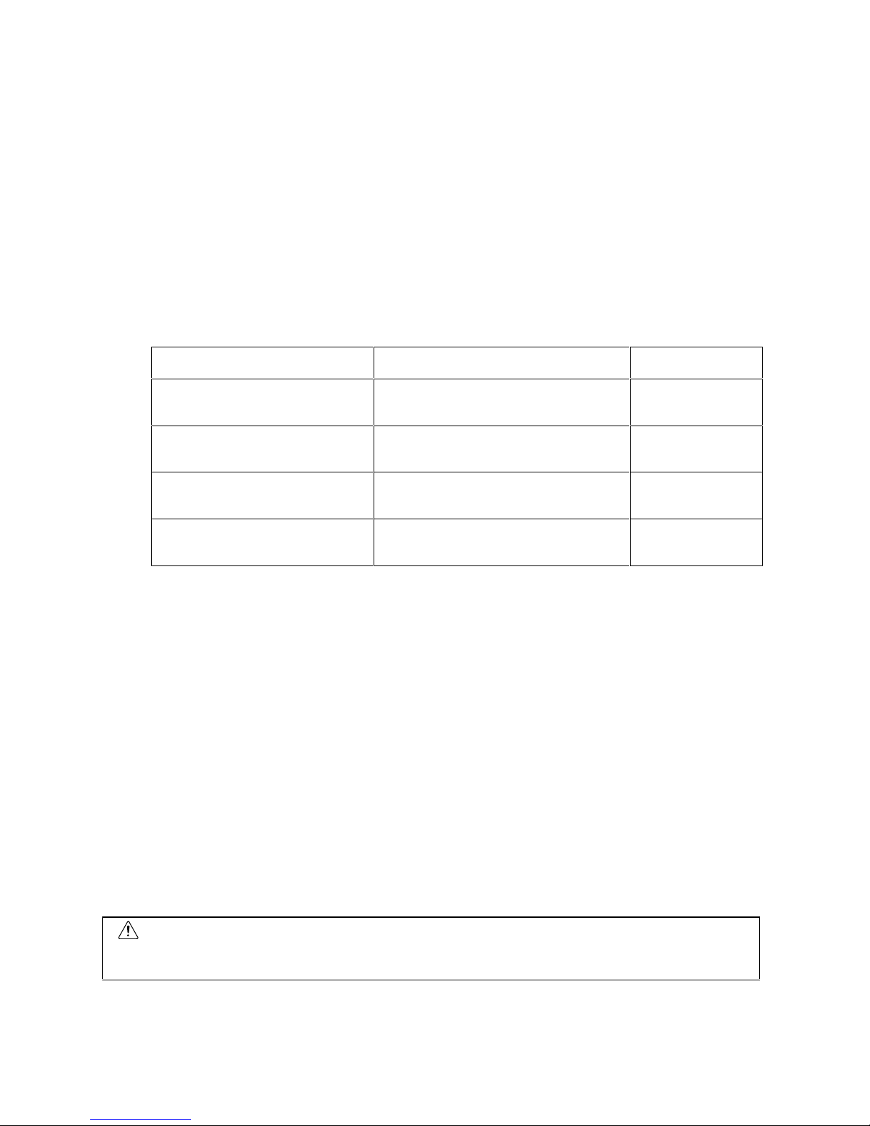
There are four manuals used with the CS1W-LC001. These manuals are listed in the following table.
The suffixes have been omitted from the catalog numbers. Be sure you are using the most recent
version for your area.
Name Contents
Cat. No.
(suffixes omitted)
SYSMAC CS1 Series
CS1W-LC001 Loop Control Unit
Operation Manual
Describes the basic running of the Loop
Control Unit (excluding detailed
descriptions of the function blocks).
W374
SYSMAC CS1 Series
CS1W-LC001 Loop Control Unit
Function Block Reference Manual
Provides detailed information on the
function blocks.
W375
SYSMAC CS1 Series
CS1W-LC001 CX-Process Tool
Operation Manual
Describes operation of the CX-Process
Tool.
W372
SYSMAC CS1 Series
CS1W-LC001 CX-Process Monitor
Operation Manual
Describes operation of the CX-Process
Monitor.
W373
Section 1 describes the features and system configuration of CS1W-LC001 Loop Control Units.
Section 2 describes the names and functions of parts, and provides other information required to
install and operate CS1W-LC001 Loop Control Units.
Section 3 provides information on the control mechanism, basic operation, exchanging data with other
Units and software, and fail-safe countermeasures for CS1W-LC001 Loop Control Units.
Section 4 describes a simple example of how to use CS1W-LC001 Loop Control Units.
Section 5 describes basic examples of PID control and examples of applied control types.
Section 6 provides information on how to use FINS commands.
Section 7 provides information on errors that may occur during running of CS1W-LC001 Loop Control
Units and guidelines for troubleshooting these errors.
Appendix 1 describes how to use the Step Ladder Program block on CS1W-LC001 Loop Control
Units, Appendix 2 describes how to use the Node Terminal blocks on CS1W-LC001 Loop Control
Units, and
Appendix 3 provides information on how to calculate the load rate, and operation execution times of
each function block and the execution times of sequence commands.
WARNING
Failure to read and understand the information provided in this manual may result in
personal injury or death, damage to the product, or product failure. Please read each
section in its entirety and be sure you unders ta nd the inf or mation provided in the section
and related sections before attempting any of the procedures or operations given.
Page 6

x
New Version Features: Ver. 2.0 to Ver.2.5
The following features had been added to the CS1W-LC001 Loop Control
Unit in upgrading from version 2.0 to version 2.5.
New Function Blocks
The following function blocks have been added: Fuzzy Logic (Block Model
016), Range Conversion (Block Model 127), Ramped Switch (Block Model
167), Level Check (Block Model 210), Ai4 Terminal (DRT1-AD04) (Block
Model 588), and Ao2Terminal (DRT1-DA02) (Block Model 589).
Notifying the CPU Unit of Function Block Changes
The CPU Unit can be informed when function blocks are downloaded by
block from the CX-Process Tool software to the Loop Control Unit. (See
note.)
*1: Similar to online editing for the Loop Control Unit.
Notification is achieved by monitoring the Function Block Change Flag (bit
15 in word n) allocated to the Loop Control Unit as a CPU Bus Unit.
Changes in the status of this flag can be used to trigger required
processing, such as notification that function blocks have changed.
Operation Specifications for Contact Type Control Target Operation
Blocks when Changing from AUTO to MAN or from Site to Central
Operation
For the ON/OFF Valve Manipulator block (Block Model 221), Motor
Manipulator block (Block Model 222), Reversible Motor Manipulator block
(Block Model 223), and Motor Opening Manipulator block (Block Model
224) only MAN status was switched to previously, but now the MAN input
is made to agree with the AUTO input to enter MAN status.
Also when the Site Manipulation Switch was changed from site to central
for these blocks, only operation was changed to the site, but now the
status is changed to MAN and the MAN input is made to agree with the
answer (feedback) input to switch to maintain status at the site while
allowing central operation.
Shorter I/O Refresh Cycle for Analog I/O Units
Although previously the external I/O refresh cycle for Mixed Analog I/O
Units was one cycle longer for Ai/Ao Terminals, specifications have been
changed so that the additional cycle is no longer required.
A Periodic Initialization Function Added to the Receive All Blocks
block (Block Model 461)
ITEM 030 (periodic initialization) and ITEM 031 (initialization interval) have
been added to the Receive All Blocks block (Block Model 461). These
ITEMs can be used to periodically initialize function block ITEM data in the
I/O memory of the CPU Unit.
ITEM Additions and Specification Changes for Other Blocks
A Block Registration Flag (ITEM 039) and the Tool Version (ITEM 110)
have been added to the System Common block (Block Model 000).
A Warning Limit (ITEM 012) has been added to the Basic PID block
(Block Model 011, Advanced PID block (Block Model 020), 2-Position
ON/OFF block (Block Model 001), 3-Position ON/OFF block (Block Model
002), Indication and Setting block (Block Model 031), Indication and
Operation block (Block Model 032), Ratio Setting block (Block Model
Page 7

xi
033), Indicator block (Block Model 034), and 4-Point Warning Indicator
block (Block Model 110).
An SP Rate-of-change Limit Time Unit (ITEM 030) has been added to
the Advanced PID block (Block Model 012).
In the Batch Flowrate Capture block (Block Model 014, the following
ITEMs have been added: Local SP Setting, Upper 4 Digits (ITEM 024),
Remote SP Setting, Upper 4 Digits (ITEM 028), Current SP Value, Upper
4 Digits (ITEM 030), Preset Value, Upper 4 Digits (ITEM 061), and Batch
Accumulated Value, Upper 4 Digits (ITEM 065) because the number of
digits has been increased from 4 to 8 digits for the Local SP, Remote SP,
Preset Value, and Batch Accumulated Value.
A Time Unit (ITEM 013) was added to the Rate-of-change Limit block
(Block Model 143).
A Reference Input Disable Switch (ITEM 020) was added to the Segment
Program 2 block (Block Model 157) to enable starting from the initial
value rather than the reference input value even when the source of the
reference input is specified.
An Output Type (ITEM 006) was added to the Contact Distributor block
(Block Model 201) to enable selecting between a constant output and a
one-shot output.
Range settings were added for individual points for the AI Terminal from
CPU Unit block (Block Model 453), AO Terminal to CPU Unit block
(Block Model 454), Ai4 Terminal block (Block Model 561), Pi4 Terminal
block (Block Model 562), and Ai8 Terminal block (Block Model 564).
A Receive Disable Switch (ITEM 225) was added to the Expanded DI
Terminal from CPU Unit block (Block Model 455) and Expanded AI
Terminal from CPU Unit block (Block Model 457) and a Send Disable
Switch (ITEM 225) was added to the Expanded DO Terminal from CPU
Unit block (Block Model 456) and Expanded AO Terminal from CPU Unit
block (Block Model 458).
A limit was set for writing ITEMs during execution of autotuning for Basic
PID (Block Model 011) and Advanced PID (Block Model 012). (Although
there was previous no limit on writing ITEMs during autotuning, ITEMs
could not be written except while process in g was disab le d, autot uning
was specified or executing, or A/M was being switched.)
Floating point decimal data can now be specified as the source data for
inputs X1 to X8. (Previously, normalized data was specified for inputs X1
to X8 and this data was scaled to floating point data. The source data
was automatically detected as normalized or floating point data and
scaling was disabled if the source data was already floating point data.
Page 8

xii
New Version Features: Ver. 1.5 to 2.0
The following features had been added to the CS1W-LC001 Loop Control
Unit in upgrading from version 1.5 to version 2.0.
New Function Blocks
The following function blocks have been added: ES100X Controller
Terminal (Block Model 045), 4-point Warning Indicator (Block Model
110), Arithmetic Operation (Block Model 126), Time Sequence Data
Statistics (Block Model 153), Receive All Blocks (Block Model 461), and
Send All Blocks (Block Model 462).
New ITEMS in Previous Function Blocks
PV Error Detection MV Output Value Traceback Time has been added to
2-position ON/OFF (Block Model 001), 3-position ON/OFF (Block Model
002), Basic PID (Block Model 011), and Advanced PID (Block Model
012).
MV Upper Limit Output Value and MV Lower Limit Output Value have
been added to Basic PID (Block Model 011), Indication and Operation
(Block Model 032), and Ratio Setting (Block Model 033).
MV Error Contact Input and MV Error Contact Display have been added
to Batch Flowrate Capture (Block Model 014), Indication and Operation
(Block Model 032), and Ratio Setting (Block Model 033).
PV Error Contact Input and PV Error Contact Display have been added
to Indication and Setting (Block Model 031), Indication and Operation
(Block Model 032), Ratio Setting (Block Model 033), and Indicator (Block
Model 034).
Inputs X1 to X8 have been added to Constant Comparator (Block Model
202).
Inputs X1 to X8 and Comparison Input R1 to R8 have been added to
Variable Comparator (Block Model 203)
Contact Inputs S33 to S224 have been added to Internal Switch (Block
Model 209).
Improved SCADA Software Support
Functions to monitor or set Loop Control Unit data from standard SCADA
software have been improved. Two new function blocks, Receive All
Blocks (Block Model 462) and Send all Blocks (Block Model 461) can be
used to access Control Block (e.g., Basic PID), Operation Block, and
External Controller Block data in the I/O memory of the CPU Unit using
CSV tags created from the CX-Process Tool software.
Flash Memory
Data Transfer between RAM and Flash Memory
The CX-Process Tool can be used to transfer function block data from
RAM in the Loop Control Unit to flash memory in the Loop Control Unit.
Data Transfer from Flash to RAM at Startup (Battery-free Operation)
Turn ON pin 2 of the DIP switch on the front of the Loop Controller Unit
will cause the contents of flash memory to be transferred to RAM in the
Loop Controller Unit each time the Unit is started. This enables operation
without worrying about the backup battery.
RS-232C Communications
A new ES100X Controller Terminal Block enables connecting an
OMRON ES100X Controller to the RS-232C port on the Loop Control
Page 9
xiii
Unit to monitor or set the ES100X via RS-232C communications or RS485 communications via RS-232C.
Restrictions in Use of Function Blocks According to Version
The following function blocks described in this manual can be used only
when Loop Control Unit CS1W-LC001 Ver.1.20 and onwards and CXProcess Tool Ver.1.20 and onwards are used:
The following function blocks can be registered on CX-Process Tool
when Loop Control Unit Ver.1.0 and CX-Process Tool Ver1 .20 or
onwards are used. However, if the data of these function blocks is
downloaded to the Loop Control Unit in major item units (units of Loop
Control Unit) when these function blocks are registered on CX-Process
Tool, an error occurs, and the download is canceled. (Other function
blocks also are not downloaded.)
The following function blocks cannot be registered on CX-Process Tool
when Loop Control Unit Ver.1.20 and onwards and CX-Process Tool
Ver.1.00 are used. For this reason, these function blocks cannot also be
downloaded to the Loop Control Unit.
If the following function blocks already exist on the Loop Control Unit and
are uploaded to CX-Process Tool, only the following function blocks are
not uploaded. (When a new upload is performed, these blocks become
empty.)
2-position ON/OFF (Block Model 001), 3-position ON/OFF (Block Model 002),
Blended PID (Block Model 013), 3-input Selector (Block Model 163), 3-output
Selector (Block Model 164), Batch Data Collector (Block Model 174), DI
Terminal from Expanded CPU Unit (Block Model 455), DO Terminal from
Expanded CPU Unit (Block Model 456), AI Terminal from Expanded CPU
Unit (Block Model 457), AO Terminal from Expanded CPU Unit (Block Model
458)
Note The version of the Loop Control Unit can be verified in the Monitor run status
screen ([Execute]-[Run]-[Monitor run status]) on CX-Process Tool.
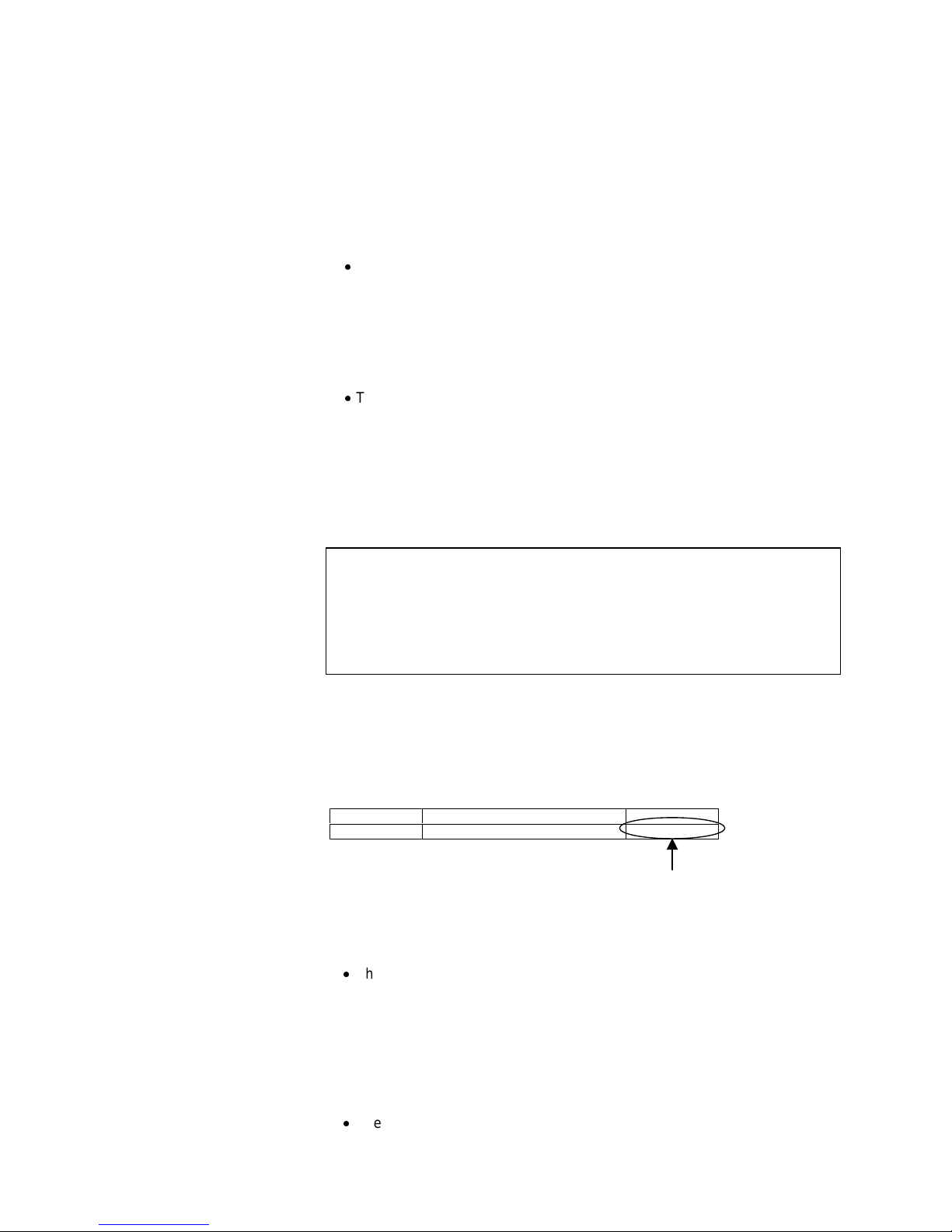
When the above function blocks are used, check in the Check System
Operation screen on CX-Process Tool beforehand that the content of ITEM
099 onwards in the System Common block (Block Model 000) is as follows.
ITEM Data name Data
099 MPU/FROM version indication V1.20V1.20
Version V1.20 and onwards must be indicated.
The following function blocks described in this manual can be used only
when Loop Control Unit CS1W-LC001 Ver.1.50 and onwards and CXProcess Tool Ver.1.50 and onwards are used:
The following function blocks can be registered on CX-Process Tool
when versions of Loop Control Unit earlier than Ver.1.50 (Ver.1.0 or
Ver.1.20) and CX-Process Tool Ver1.50 or onwards are used. However,
if the data of these function blocks is downloaded to the Loop Control
Unit in major item units (units of Loop Control Unit) when these function
blocks are registered on CX-Process Tool, an error occurs, and only
those function blocks are not downloaded. (Other function blocks are
downloaded successfully.)
The following function blocks cannot be registered on CX-Process Tool
when Loop Control Unit Ver.1.50 and onwards and versions of CX-
Page 10

xiv
Process Tool earlier than Ver.1.50 (Ver.1.00 or Ver. 1.20) are used. For
this reason, these function blocks cannot also be downloaded to the Loop
Control Unit.
If the following function blocks already exist on the Loop Control Unit and
are uploaded to CX-Process Tool, only the following function blocks are
not uploaded. (When a new upload is performed, these blocks become
empty.)
Segment Program (Block Model 157), Accumulated Value Input Adder (Block
Model 182), Accumulated Value Input Multiplier (Block Model 183), Constant
Comparator (Block Model 202), Variable Comparator (Block Model 203),
Clock Pulse (Block Model 207), ON/OFF Valve Manipulator (Block Model
221), Motor Manipulator (Block Model 222), Reversible Motor Manipulator
(Block Model 223), Motor Opening Manipulator (Block Model 224)
Likewise, the following functions can be used only when Loop Control Unit
CS1W-LC001 Ver.1.50 and onwards and CX-Process Tool Ver.1.50 and
onwards are used:
The following ITEMs can be set on CX-Process Tool when versions of
Loop Control Unit earlier than Ver.1.50 (Ver.1.0 or Ver.1.20) and CXProcess Tool Ver1.50 or onwards are used. However, if the data of these
ITEMs is downloaded to the Loop Control Unit when these ITEMs are set
on CX-Process Tool, only those ITEMs are not downloaded. (Other
ITEMs are downloaded successfully.)
The following ITEMs cannot be set on CX-Process Tool when Loop
Control Unit Ver.1.50 or onwards and versions of CX-Process Tool earlier
than Ver.1.50 (Ver.1.00 or Ver. 1.20) are used. For this reason, these
ITEMs cannot also be downloaded to the Loop C ontro l Unit.
If a download in major item units (units of Loop Control Unit) or a
download in function blocks units including initial setting data is
performed, the respective defaults are set to the following ITEMs on the
Loop Control Unit.
If the following ITEMs are already set on the Loop Control Unit and are
uploaded to the CX-Process Tool, only the following ITEMs are not
uploaded.
AT (auto-tuning) functions of Basic PID block (Block Model 011) and
Advanced PID (Block Model 012), and wait function and additional steps
(step numbers 8 to 15) of the Ramp Program block (Block Model 155)
Note 1 For details on which actual ITEM this restriction applies to, refer to the ITEM
list for the relevant function block in the Function Block Reference Manual.
Note 2 The version of the Loop Control Unit can be verified in the Monitor run status
screen ([Execute]-[Run]-[Monitor run status]) on CX-Process Tool.
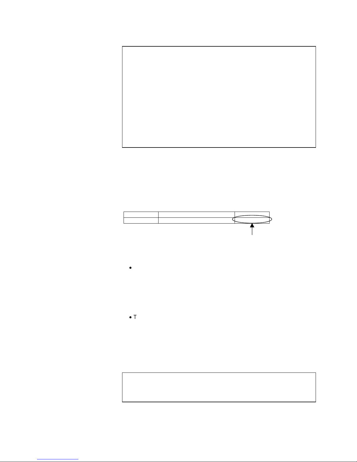
When the above function blocks are used, check in the Check System
Operation screen on CX-Process Tool beforehand that the content of ITEM
099 onwards in the System Common block (Block Model 000) is as follows.
ITEM Data name Data
099 MPU/FROM version indication V1.50V1.50
Version V1.50 and onwards must be indicated.
Page 11

xv
The following function blocks described in this manual can be used only
when Loop Control Unit CS1W-LC001 Ver. 2.00 and onwards and CXProcess Tool Ver. 2.00 and onwards are used:
The following function blocks can be registered on CX-Process Tool
when versions of Loop Control Unit earlier than Ver. 2.00 (Ver. 1.0,
Ver. 1.20, or Ver. 1.50) and CX-Process Tool Ver 1.50 or onwards are
used. However, if the data of these function blocks is downloaded to the
Loop Control Unit in major item units (units of Loop Control Unit) when
these function blocks are registered on CX-Process Tool, an error
occurs, and only those function blocks are not downloaded. (Other
function blocks are downloaded successfully.)
The following function blocks cannot be registered on CX-Process Tool
when Loop Control Unit Ver. 2.00 and onwards and versions of CXProcess Tool earlier than Ver. 2.00 (Ver. 1.00 Ver. 1.20, or Ver. 1.50) are
used. For this reason, these function blocks cannot also be downloaded
to the Loop Control Unit.
If the following function blocks already exist on the Loop Control Unit and
are uploaded to CX-Process Tool, only the following function blocks are
not uploaded. (When a new upload is performed, these blocks become
empty.)
ES100X Controller Terminal (Block Model 045), 4-point Warning Indicator
(Block Model 110), Arithmetic Operation (Block Model 126), Time Sequence
Data Statistics (Block Model 153), Receive All Blocks (Block Model 461),
Send All Blocks (Block Model 462)
Likewise, the following functions can be used only when Loop Control Unit
CS1W-LC001 Ver. 2.00 and onwards and CX-Process Tool Ver. 2.00 and
onwards are used:
The following ITEMs can be set on CX-Process Tool when versions of
Loop Control Unit earlier than Ver. 2.00 (Ver. 1.00 Ver. 1.20, or Ver. 1.50)
and CX-Process Tool Ver, 2.00 or onwards are used. However, if the
data of these ITEMs is downloaded to the Loop Control Unit when these
ITEMs are set on CX-Process Tool, only those ITEMs are not
downloaded. (Other ITEMs are downloaded successfully.)
The following ITEMs cannot be set on CX-Process Tool when Loop
Control Unit Ver. 2.0 or onwards and versions of CX-Process Tool earlier
than Ver. 2.00 (Ver. 1.00 Ver. 1.20, or Ver. 1.50) are used. For this
reason, these ITEMs cannot also be downloaded to the Loop Control
Unit.
If a download in major item units (units of Loop Control Unit) or a
download in function blocks units including initial setting data is
performed, the respective defaults are set to the following ITEMs on the
Loop Control Unit.
If the following ITEMs are already set on the Loop Control Unit and are
uploaded to the CX-Process Tool, only the following ITEMs are not
uploaded.
Page 12
xvi
MV Output Retrace Time for PV Error has been added to 2-position ON/OFF (Block
Model 001), 3-position ON/OFF (Block Model 002), Basic PID (Block Model 011), and
Advanced PID (Block Model 012).
High MV Limit Output and Low MV Limit Output have been added to Basic PID (Block
Model 011), Indication and Operation (Block Model 032), and Ratio Setting (Block
Model 033).
MV Error Input and MV Error Display have been added to Batch Flowrate Capture
(Block Model 014), Indication and Operation (Block Model 032), and Ratio Setting
(Block Model 033).
PV Error Input and PV Error Display have been added to Indication and Setting (Block
Model 031), Indication and Operation (Block Model 032), Ratio Setting (Block Model
033), and Indicator (Block Model 034).
Inputs X1 to X8 have been added to Constant Comparator (Block Model 202).
Inputs X1 to X8 and Comparison Input R1 to R8 have been added to Variable
Comparator (Block Model 203)
Contact Inputs S33 to S224 have been added to Internal Switch (Block Model 209).
Note 1 For details on which actual ITEM this restriction applies to, refer to the ITEM
list for the relevant function block in the Function Block Reference Manual.
Note 2 The version of the Loop Control Unit can be verified in the Monitor run status
screen ([Execute]-[Run]-[Monitor run status]) on CX-Process Tool.
When the above function blocks are used, check in the Check System
Operation screen on CX-Process Tool beforehand that the content of ITEM
099 onwards in the System Common block (Block Model 000) is as follows.
ITEM Data name Data
099 MPU/FROM version indication V2.00V2.00
Version V2.00 and onwards must be indicated.
The following function blocks described in this manual can be used only
when Loop Control Unit CS1W-LC001 Ver.2.50 and onwards and CXProcess Tool Ver.2.50 and onwards are used:
The following function blocks can be registered on CX-Process Tool
when the Loop Control Unit is pre-Ver.2.50 and the CX-Process Tool is
Ver 2.50 or later. However, if the data of these function blocks is
downloaded to the Loop Control Unit in major item units (units of Loop
Control Unit) when these function blocks are registered on CX-Process
Tool, an error occurs, and the download is canceled. (Other function
blocks will be downloaded normally.)
The following function blocks cannot be registered on CX-Process Tool
when the Loop Control Unit is Ver. 2.50 or later and CX-Process Tool is
pre-Ver.2.50. For this reason, these function blocks cannot also be
downloaded to the Loop Control Unit.
If the following function blocks already exist on the Loop Control Unit and
are uploaded to CX-Process Tool, only the following function blocks are
not uploaded. (When a new upload is performed, these blocks become
empty.)
Fuzzy Logic (Block Model 016), Range Conversion (Block Model 127), Level
Check (Block Model 210), Ai4 Terminal (DRT1-AD04) (Block Model 588),
Ao2 Terminal (DRT1-DA02) (Block Model 589)
Likewise, the following functions can be used only when Loop Control Unit
CS1W-LC001 Ver. 2.50 or onwards and CX-Process Tool Ver. 2.50 or
onwards are used:
Page 13

xvii
The following ITEMs can be set on CX-Process Tool when versions of
Loop Control Unit earlier than Ver. 2.50 and CX-Process Tool Ver. 2.50
or onwards are used. However, if the data of these ITEMs is downloaded
to the Loop Control Unit when these ITEMs are set on CX-Process Tool,
only those ITEMs are not downloaded. (Other ITEMs are downloaded
successfully.)
The following ITEMs cannot be set on CX-Process Tool when Loop
Control Unit Ver. 2.50 or onwards and versions of CX-Process Tool
earlier than Ver. 2.50 are used. For this reason, these ITEMs cannot also
be downloaded to the Loop Control Unit.
If a download in major item units (units of Loop Control Unit) or a
download in function blocks units including initial setting data is
performed, the respective defaults are set to the following ITEMs on the
Loop Control Unit.
If the following ITEMs are already set on the Loop Control Unit and are
uploaded to the CX-Process Tool, only the following ITEMs are not
uploaded.
Block Registration Flag (ITEM 039) and Tool Version (ITEM 110) in System Common
(Block Model 000).
Warning Limit (ITEM 012) in Basic PID (Block Model 011, Advanced PID (Block
Model 020), 2-Position ON/OFF (Block Model 001), 3-Position ON/OFF (Block Model
002), Indication and Setting (Block Model 031), Indication and Operation (Block Model
032), Ratio Setting (Block Model 033), Indicator (Block Model 034), and 4-Point
Warning Indicator (Block Model 110).
SP Rate-of-change Limit Time Unit (ITEM 030) in Advanced PID (Block Model 012).
Local SP Setting, Upper 4 Digits (ITEM 024), Remote SP Setting, Upper 4 Digits
(ITEM 028), Current SP Value, Upper 4 Digits (ITEM 030), Preset Value, Upper 4
Digits (ITEM 061), and Batch Accumulated Value, Upper 4 Digits (ITEM 065) in Batch
Flowrate (Block Model 014).
Time Unit (ITEM 013) in Rate-of-change Limit (Block Model 143).
Reference Input Disable Switch (ITEM 020) in Segment Program 2 (Block Model
157).
Output Type (ITEM 006) in Contact Distributor (Block Model 201).
Range settings in AI Terminal from CPU Unit (Block Model 453), AO Terminal to CPU
Unit (Block Model 454), Ai4 Terminal (Block Model 561), Pi4 Terminal (Block Model
562), and Ai8 Terminal (Block Model 564).
Receive Disable Switch (ITEM 225) in Expanded DI Terminal from CPU Unit (Block
Model 455) and Expanded AI Terminal from CPU Unit (Block Model 457) and Send
Disable Switch (ITEM 225) in Expanded DO Terminal from CPU Unit (Block Model
456) and Expanded AO Terminal from CPU Unit (Block Model 458).
Note 1 For details on which actual ITEM this restriction applies to, refer to the ITEM
list for the relevant function block in the Function Block Reference Manual.
Note 2 The version of the Loop Control Unit can be verified in the Monitor run status
screen ([Execute]-[Run]-[Monitor run status]) on CX-Process Tool.
When the above function blocks are used, check in the Check System
Operation screen on CX-Process Tool beforehand that the content of ITEM
099 onwards in the System Common block (Block Model 000) is as follows:
ITEM Data name Data
099 MPU/FROM version indication V2.50V2.50
Version V2.50 and onwards must be indicated.
Page 14

xviii
PRECAUTIONS
This section provides general precautions for using the Programmable Controller (PC) and related devices.
The information contained in this section is important for the safe and reliable application of the
Programmable Controller. You must read this section and understand the information contained
before attempting to set up or operate a PC system.
1 Intended Audience................................................................................................................................................. xix
2 General Precautions .............................................................................................................................................. xix
3 Safety Precautions ................................................................................................................................................ xix
4 Operating Environment Precautions................................................................................................................... xxi
5 Application Precautions ........................................................................................................................................ xxi
6 EC Directives........................................................................................................................................................ xxiv
7 Other Applicable Directives................................................................................................................................ xxiv
Page 15

Safety Precautions 3
xix
1 Intended Audience
This manual is intended for the following personnel, who must also have
knowledge of electrical systems (an electrical engineer or the equivalent) and
knowledge about instrumentation system.
Personnel in charge of installing FA systems
Personnel in charge of designing FA systems
Personnel in charge of managing FA systems and facilities
2 General Precautions
The user must operate the product according tot he performance
specifications described in the operation manuals.
Before using the product under conditions which are not described in this
manual or applying the product to nuclear control systems, railroad systems,
aviation systems, vehicles, combustion systems, medical equipment,
amusement machines, safety equipment, petrochemical plants, and other
systems, machines, and equipment that may have a serious influence on
lives and property if used improperly, consult your OMRON representative.
Make sure that the ratings and performance characteristics of the product are
sufficient for the systems, machines, and equipment, and be sure to provide
the system, machines and equipment with double safety mechanism.
This manual provides information for running OMRON Loop Control Units. Be
sure to read this manual before attempting to use the Loop Control Units and
related software (CX-Process Tool and CX-Process Monitor) and keep this
manual close at hand for reference during running.
WARNING
It is extremely important that a PC and all PC Units be used for the specified
purpose and under the specified conditions, especially in applications that
directly or indirectly affect human life. You must consult with your OMRON
representative before applying a PC System to the above-mentioned
applications.
3 Safety Precautions
WARNING
Do not attempt to take any Unit apart while power is being supplied. Doing
so may result in electric shock.
WARNING
Provide safety measures in external circuits (i.e., not in the Programmable
Controller), including the following items, to ensure safety in the system if an
abnormality occurs due to malfunction of the PC or another external factor
affecting the PC operation. Not doing so may result in serious accidents.
Emergency stop circuits, interlock circuits, limit circuits, and similar
safety measures must be prov ided in external control circuit s.
The PC will turn OFF all outputs when its self-diagnosis function detects
any error or when a severe failure alarm (FALS) instruction is executed.
As a countermeasure for such errors, external safety measures must be
provided to ensure safety in the system.
Page 16

Safety Precautions 3
xx
The PC outputs may remain ON or OFF due to deposition or burning of
the output relays or destruction of the output transistors. As a
countermeasure for such problems, external safety measures must be
provided to ensure safety in the system.
When the 24-VDC output (service power supply to the PC) is overloaded
or short-circuited, the voltage may drop and result in the outputs being
turned OFF. As a countermeasure for such problems, external safety
measures must be provided to ensure safety in the system.
WARNING
Check the following items before starting to run the Loop Control Unit:
Analog Input/Output Units used in combination with the Loop Control Unit
must be mounted correctly, and the unit number set on the front panel of
the Analog Input/Output Unit must match the unit number set on the Field
Terminal block. If the unit numbers do not match, input/output (read/write)
is performed on the data of another Special I/O Unit (whose unit number
is set on the Field Terminal block).
The defaults of the System Common block on the Loop Control Unit must
be set correctly. In particular, make sure that the Data Memory (D) for the
Node Terminals on the CPU Unit used by the Loop Control Unit is not set
in duplicate for other applications on the PC. If the application of the Data
Memory is set in duplicate, the PC system may act unexpectedly and
cause injury.
When writing data to the I/O memory in the CPU Unit with function blocks
(e.g., using Send All Blocks, Expanded DO/AO Terminal to CPU Unit, or
DO/AO Terminal to CPU Unit), be sure that the words written to in the I/O
memory are not being used for any other purpose. If I/O memory words
are allocated to more than one purpose, the PC system may act
unexpectedly and cause injur y.
WARNING
Do not perform processing in such a way that the Loop Control Unit and
CPU Unit perform writing on identical I/O memory addresses allocated to an
contact output or analog output to an external Unit. If writing is performed on
identical addresses, the externally connected load may act unexpectedly
and cause injury.
Page 17

Application Precautions 5
xxi
4 Operating Environment Precautions
Caution
Do not operate the control system in the following places:
Locations subject to direct sunlight
Locations subject to temperature or humidity outside the range specified
in the specifications
Locations subject to condensation as the result of severe changes in
temperature
Locations subject to corrosive or flammable gases
Locations subject to dust (especially iron dust) or salts
Locations subject to exposure to water, oil, or chemicals
Locations subject to shock or vibration
Caution
Take appropriate and sufficient countermeasures when installing systems in
the following locations:
Locations subject to static electricity or other forms of noise
Locations subject to strong electromagnetic fields
Locations subject possible exposure to radioactivity
Locations close to power supplies
Caution
The operating environment of the PC System can have a large effect on the
longevity and reliability of the system. Improper operating environments can
lead to malfunction, failure, and other unforeseeable problems with the PC
System. Be sure that the operating environment is within the specified
conditions at installation and remains within the specified conditions during
the life of the system.
5 Application Precautions
Observe the following precautions when using the PC.
WARNING
Always heed these precautions. Failure to abide by the following
precautions could lead to serious or possibly fatal injury.
Always connect to a class-3 ground (to 100
or less) when installing the
Units. Not connecting to a class-3 ground may result in electric shock.
Always turn OFF the power to the PC before attempting any of the
following. Not turning OFF the power may result in malfunction or electric
shock.
Mounting or dismounting I/O Units
Assembling the Units
Setting DIP switches or unit number setting switches
Connecting or wiring the cables
Connecting or disconnecting the connectors
Page 18

Application Precautions 5
xxii
Caution
Failure to abide by the following precautions could lead to faulty operation of
the PC or the system, or could damage the PC or PC Units. Always heed
these precautions.
To hold analog outputs or contact outputs at specific values (for example,
maximum value or minimum value) when the Loop Control Unit has
stopped running, create a Step Ladder Program on the CPU Unit so that
each of the allocated relays on the Analog Output Unit or Contact Output
Unit are set to a specific value taking the b contact of the Loop Control
Unit Running flag (bit 00 allocated relay n word) as the input conditions.
When a fatal error occurs on the CPU Unit (including during execution of
the FALS command), the Loop Control Unit also stops running. To hold
the analog output to the previous value before the stop occurred, and to
set the analog output to either the minimum value or maximum value, use
the output hold function of the Analog Output Unit or Analog Input/Output
Unit.
Before turning ON the power to the PC, make sure that the facilities are
safe.
The analog output values and contact outputs from the Loop Control Unit
are updated at the same time that the power to the PC is turned ON
regardless of the operation mode of the CPU Unit (including the
PROGRAM mode). (Internally, the analog output values and contact
outputs are sent via the CPU Unit to the Basic I/O Unit and Analog Output
Unit.)
The Loop Control Unit itself does not have a human interface. So, an
external interface such as CX-Process Monitor must be provided.
Fail-safe measures must be taken by the customer to ensure safety in the
event of incorrect, missing, or abnormal signals caused by broken signal
lines, momentary power interruptions or other causes.
Before touching the PC, be sure to first touch a grounded metallic object
in order to discharge any static build-up.
Otherwise, it might result in a malfunction or damage.
Before you replace the battery while the Loop Control Unit is ON, be sure
to touch a grounded metal object to discharge any static electricity from
your body
Never short-circuit the plus and minus poles of the battery, charge,
disassemble or heat the battery, or throw the battery into a fire.
Interlock circuits, limit circuits, and similar safety measures in external
circuits (i.e. not in the Programmable Controller) must be provided by the
customer.
Always use the power supply voltage specified in this manual. An
incorrect voltage may result in malfunction or burning.
Take appropriate measures to ensure that the specified power with the
rated voltage and frequency is supplied. Be particularly careful in places
where the power supply is unstable. An incorrect power supply may result
in malfunction.
Install external breakers and take other safety measures against short-
circuiting in external wiring. Insufficient safety measures against shortcircuiting may result in burning.
Do not apply voltages to input sections in excess of the rated input
Page 19

Application Precautions 5
xxiii
voltage. Excess voltages may result in burning.
Do no apply voltages or connect loads in excess of the maximum
switching capacity to output sections. Excess voltage or leads may result
in burning.
Turn OFF the power to the PC before performing the following operations:
Mounting or removing the Loop Control Unit, CPU Unit, or the Memory
Pack
Assembling Racks
Setting the DIP switch or unit number setting switch
Performing wiring or connecting cables
When connecting or disconnecting cables
Do not attempt to disassemble, repair, or modify any Units.
Be sure to confirm that the DIP switch and the Data Memory (D) are
properly set.
Leave the dust-protection label attached to the top Unit when wiring.
Removing the label ma y result in malf unc tion.
Remove the labels after the completion of wiring to ensure proper heat
dissipation. Leaving the label attached may result in malfunction.
Mount the Unit only after checking the terminal block and switch settings
completely.
Be sure that all mounting screws, terminal screws, and cable connector
screws are tightened to the torque specified in the user manuals.
Incorrect tightening torque may result in malfunction.
Check the user program for proper execution before actually running it on
the Unit. Not checking the program may result in an unexpected
operation.
Use crimp terminals for wiring. Do not connect stranded wires directly to
terminals. Connection of bare stranded wires may result in burning.
Double-check all the wiring before turning ON the power supply. Incorrect
wiring may result in burning.
Confirm that no adverse effect will occur in the system before attempting
any of the following:
Changing the operating mode of the PC
Force-setting/force-resetting of any contact in memory
Changing the present value or any set value in memory
Page 20

Other Applicable Directives 7
xxiv
6 EC Directives
CS1 Series Units confirm to EC Directives. For the system to conform to EC
Directives, however, the following precautions must be adhered to.
CS1 Series Units must be installed within control panel.
Use reinforced insulation of double insulation for the DC power supplies
used for the I/O power supplies.
CS1 Series Units that meet EC Directives also meet the Common Emission
Standard (EN50081-2). The measure necessary to ensure that standards,
such as the radiated emission standard (10 m), are met, however, will vary
depending on the overall configuration of the control panel, the other
devices to the control panel, and wiring. You must therefore confirm that
EC Directives are met for the overall machine or device.
7 Other Applicable Directives
Applicable Directives
EMC Directive
Low Voltage Directive
EMC and Low Voltage Directives
EMC Directive
In order that OMRON products can be used with any machinery and in
combination with other manufacturer’s equipment, the products themselves
are designed to comply with EMC standards (see Note), so that the
assembled machinery or device can then also easily comply with EMC
standards.
Even if machinery and equipm ent complies with EMC standards befor e
assembly, this compliance may change depending on the device, the
configuration of the control panel, and wiring, so OMRON cannot guarantee
that a particular system complies with the directive. You must therefore
confirm that EMC Directives are met for the overall machine or device.
Note EMC: One directive relating to Electro-Magnetic Compatibility
EMS: Electro-Magnetic Susceptibility standard EN61131-2
EMI: Electro-Magnetic Interference standard EN50081-2
Common Emission Standard EN50081-2, radiated emission standard (10 m)
Low Voltage Directive
The Low Voltage Directive provides that necessary safety standards are
guaranteed for devices operating at voltages of 50 to 1,000 VAC or 75 to
1,500 VDC.
Page 21

Outline Section 1-1
1
SECTION 1
Specifications
1-1 OUTLINE ........................................................................................................... 2
1-1-1 Outline........................................................................................................................................................... 2
1-1-2 Features.......................................................................................................................................................... 3
1-1-3 Basic System Configuration.......................................................................................................................... 6
1-1-4 Application Examples.................................................................................................................................... 6
1-1-5 Loop Control Unit Mechanism...................................................................................................................... 9
1-1-6 Overall Mechanism of Data Exchange........................................................................................................ 16
1-1-7 Internal Mechanism of Loop Control Unit .................................................................................................. 19
1-1-8 List of Function Blocks ............................................................................................................................... 20
1-2 CONFIGURATION OF INSTRUMENTATION SYSTEM ....................... 26
1-2-1 Mounting Location...................................................................................................................................... 26
1-2-2 Determining the System Configuration....................................................................................................... 27
1-2-3 Description of Basic System Configuration ................................................................................................ 29
1-3 SPECIFICATIONS.......................................................................................... 37
1-3-1 General Specifications................................................................................................................................. 37
1-3-2 Specifications............................................................................................................................................... 37
1-3-3 Function Specifications ............................................................................................................................... 38
1-3-4 Outline of PID Block Specifications............................................................................................................ 41
1-3-5 Software Specifications............................................................................................................................... 43
1-4 HOW TO USE FUNCTION BLOCKS FOR SPECIFIC OPERATIONS.48
1-5 BASIC PROCEDURE FOR USING THE LOOP CONTROL UNIT........ 52
Page 22

Outline Section 1-1
2
1-1 Outline
1-1-1 Outline
The Loop Control Unit is capable of the following:
- PID operation with up to 32 loops
1
- Operation of up to 250 various processes
- Basic logic sequence control
- Process progression control
The Loop Control Unit can also be used as an alarm/monitor terminal on a
computer without the need to use PID control functions.
The Loop Control Unit belongs to the CPU Bus Unit group for the CS1 series
PCs.
1 The maximum number of control loops is restricted by the operation
cycle. In most cases (when there is no Step Ladder Program), the
maximum number of control loops is 32 loops at operation cycles of 2, 1,
and 0.5 seconds; 16 loops at an operation cycle of 0.2 seconds; and
eight loops at an operation cycle of 0.1 seconds.
The Loop Control Unit itself has no external I/O functions. So, it must be used
in a pair with a unit having an external interface such as an Analog I/O Unit or
Basic I/O Unit. The Loop Control Unit exchanges data with the Unit having
the external interface via the CPU Unit I/O memory.
You can achieve all functions (operation functions/designation of field
input/output) simply by combining Control blocks, Operation blocks, and
other function blocks. This allows you to easily build a professional
instrumentation system on your PC (programmable controller).
The following functions can be achieved by function blocks:
Internal Operations
Control (max. 32 function blocks): 2-position ON/OFF Basic PID,
Advanced PID, Ratio Setting, etc.
Operation (max. 250 function blocks): Alarm/Signal restrictions/Hold,
Arithmetic (addition, subtraction, multiplication and division), Functions
(Square Root, Absolute Value, Segment Linearizer, etc.), Time Functions
(Lead/Delay, Dead Time, Ramp Program, etc.), Pulse Train Operation
(Accumulator), Signal Selection/Switching (Rank Selector, Constant
Selector, etc.), Sequential Control (Timers, Counter, etc.)
External controllers (max. 32 function blocks): ES100X Controller Terminal
Logic sequence/step progression control (max. 100 function blocks): Step
Ladder Program
External I/O
Each of the points on the Analog I/O Unit and Basic I/O Unit is read and
written by the Field Terminal block (max. 80 function blocks).
Specified contacts or analog data on the CPU Unit is read and written by
the CPU Unit Terminal block (max. 16 function blocks) and the Expanded
CPU Unit Terminal block (max. 32 function blocks).
Page 23

Outline Section 1-1
3
Data for Control, Operation, and External Controller blocks can be read
and written for SCADA software by using the Send All Blocks block and
Receive All Blocks block .
Contacts, analog data, and Control blocks (max. 32 function blocks) are
sent to the computer, and contacts with a Loop Control Unit mounted on a
networked PC or analog data are read and written (send: max. 50 function
blocks, receive: max. 100 function blocks) by the Node Terminal block.
Note Data in each of the function blocks can also be read and written by issuing
the FINS command to the Loop Control Unit by the CMND (DELIVER
COMMAND) command in the Step Ladder Program on the CPU Unit.
1-1-2 Features
All Functions Achieved by Using Only Function Blocks (operation
functions/designation of field input/output)
Wiring function blocks in the software allows you to achieve not only
combinations of operation blocks but also all functions including specification
of field I/Os.
Almost All Control Types Freely Achieved by Combining Function
Blocks
In addition to regular PID control, cascade control, feedforward control, dead
time compensation control, override control and other special control types
can be achieved as desired by combining function blocks for up to 32 loops.
Control can also be easily configured for processes with prolonged dead
time, non-linear processes, and processes involving fluctuating loads.
Changes in control type after start of operation can also be flexibly
accommodated.
Easy Integration of Loop Control and Sequence control
Data exchange with the CPU Unit and logic sequence/step progression
control on the Loop Control Unit can be achieved. This allows you to easily
integrate analog loop control and sequence control.
Data Exchange with Analog I/O Unit and Basic I/O Unit Achieved by
Function Blocks
External analog I/O and contact I/O can be easily input and output by
specifying the Analog I/O Unit on the PC and the Basic I/O Unit as the
function block.
Logic Sequence Control and Step Progression Control Achieved by
Function Blocks
Up to 4000 commands (mnemonic LOAD, OUT, etc.) can be programmed as
a function block. This block can be further divided into separate steps so that
program execution moves between steps when preset conditions are
satisfied. This allows you to easily control step progression, for example, on
devices that are analog process intensive.
Page 24

Outline Section 1-1
4
Note Command execution on the Loop Control Unit is slower (0.1 to 2 second
operation cycle) than that on a CPU Unit. So, these commands are used for
programming AND and OR conditions when combining function blocks and
specifying (Remote/Local, Auto/Manual, etc.) function block operating
conditions.
Data Exchange with CPU Unit Achieved by Function Blocks
Contacts and analog data in CPU Unit I/O memory can also be read and
written constantly (at each operation cycle) by specifying the I/O numbers of
function blocks. This facilitates cooperative control in setting up and
monitoring Step Ladder Programs on the CPU Unit.
Functions to monitor or set Loop Control Unit data from standard SCADA
software have been improved. Two new function blocks, Receive All Blocks
(Block Model 462) and Send all Blocks (Block Model 461) can be used to
access Control Block (e.g., Basic PID), Operation Block (e.g., math
functions), and External Controller Block (ES100X) data in the I/O memory of
the CPU Unit using CSV tags created from the CX-Process Tool software.
I/O with Host Computer (via CPU Unit) Achieved by Function Blocks
Data can also be sent to the host computer connected on the Host Link or
the computer (on which the Controller Link Support Boar d is m ounted)
connected on the Controller Link by designating the function block. (Note,
however, that data is only stored to the Data Memory for the Node Terminals
on the CPU Unit. Subsequent processing is dependent on accessing by FINS
commands issued from the host computer or on the Data Link with the
computer on the Controller Link.)
The contacts and analog data of the Loop Control Unit mounted on a
networked PC can also be read and written via the Controller Link by
designating the function blocks. (Note, however, that data is only stored to
the Data Memory for the Node Terminals on the CPU Unit. Subsequent
processing is dependent on the Data Link with the PC on the Controller Link.
Message Communications by FINS Commands
Data on each of the function blocks can also be read and written as desired
by issuing FINS commands by the CMND (DELIVER COMMAND) command
in the Step Ladder Program on the CPU Unit or by issuing FINS commands
from the host computer. Function block data can also be read and written
from PCs (CPU Units) on other networked nodes.
Simulated Software Wiring between Function Blocks
CX-Process Tool allows you to simulate wiring between function blocks in the
software by joining lines on your computer’s screen.
Simulated Monitoring of Monitor, Graphic Monitor, and Alarms
CX-Process Monitor or SCADA software can be used to monitor the control
state and change settings on the Loop Control Unit in a screen that is similar
to a field device. CX-Process Monitor also supports graphic monitoring,
generation of trend graphs, alarm monitoring, alarm logging and operation
logging of each of the instrumentation components. Commercially available
SCADA software can also be used to create a monitoring system.
Page 25

Outline Section 1-1
5
The CX-Process Tool is used to create tags for the CX-Process Monitor or
for SCADA software to enable accessing Loop Control Unit Data.
Connect ES100X Controllers Ext e rnall y
ES100X Controllers can be connected to the RS-232C port on the Loop
Control Unit and ES100X External Controller Terminal function blocks can be
used to monitor ES100X parameters, such as the SP, PV, and MV, and to
set ES100X parameters, such as the SP and PID constants. Converting from
RS-232C to RS-422A/485 enables connecting up to 32 ES100X Controllers.
Battery-free Operation
You now have a choice. You can either store function block data in RAM in
the Loop Control Unit and back it up with a battery or you can eliminate the
need for a backup battery by setting the Loop Control Unit to transfer flash
memory contents to RAM each time power is turned ON. (Automatic transfer
from flash memory is set using the DIP switch.)
Page 26
Outline Section 1-1
6
1-1-3 Basic System Configuration
1, 2, 3… 1. Unit Having External Interfac e Functi ons
The Loop Control Unit itself does not have external analog I/O and
external contact I/O functions. So, it must be used in combination with a
Unit having external interface functions such as an Analog I/O Unit as
shown in the example figures in the following pages.
2. CX-Process Tool
The Loop Control Unit itself does not have a human-machine interface for
preparing function block data. So, function block data must be prepared
on CX-Process Tool, and then downloaded to the Loop Control Unit for
use as shown in the example figures in the following pages.
3. CX-Process Monitor
The Loop Control Unit itself does not have a human-machine interface for
setting the Set Point and PID constant values, and displaying the PV. So,
the Set Point and PID constant values must be set, and PV monitored on
CX-Process Monitor as shown in the example figures in the following
pages.
1-1-4 Application Examples
The Loop Control Unit can be used, for example, to build control systems
capable of high-density monitoring of analog data through to advanced
control of instrumentation such as in the following four examples.
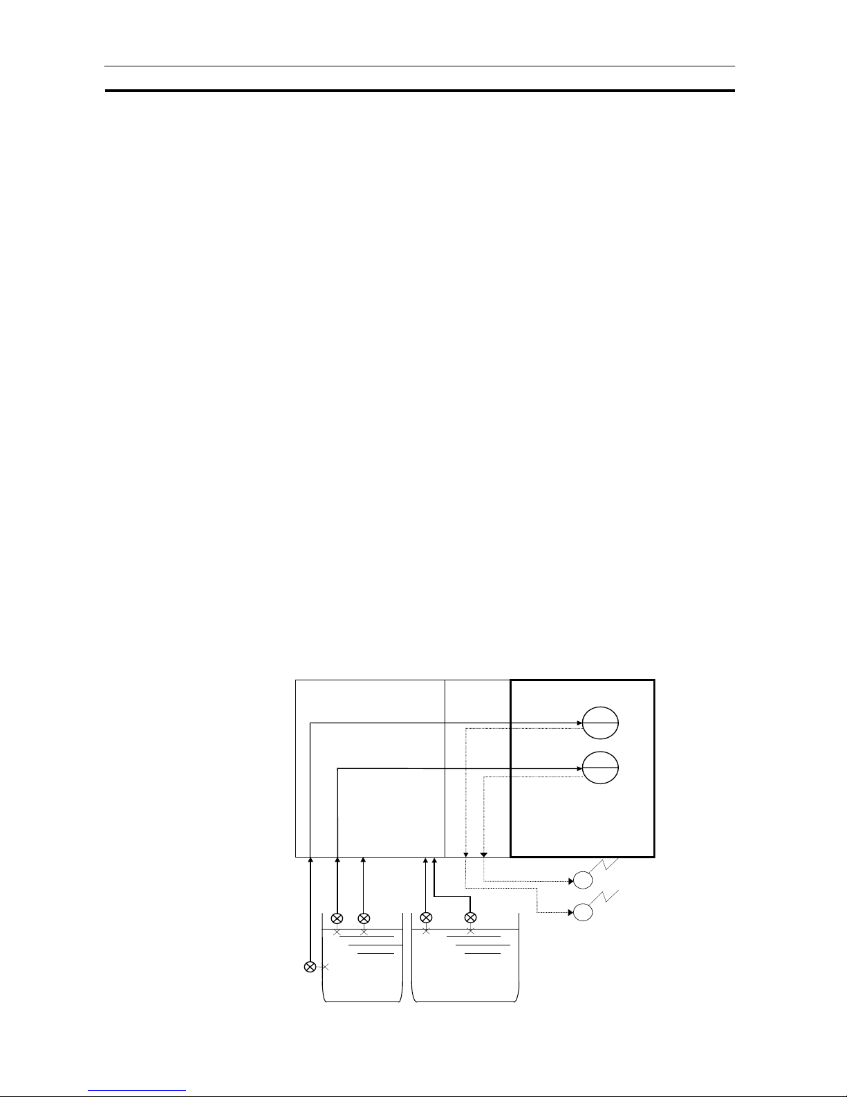
High-density Monitoring of Waterworks and Sewage Systems
Loop Control Unit
Contact
Output Un it
Analog Input
Unit
Alarm
Alarm
Temperature
PH
Temper-
ature
PH
Alarm
output
Alarm
output
Alarm
Alarm
Temper-
ature
Page 27

Outline Section 1-1
7
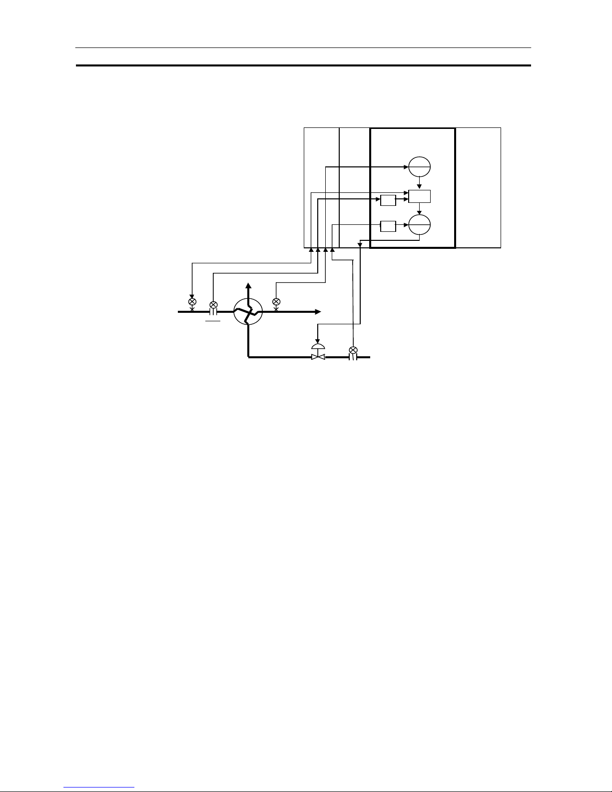
Temperature Control of Kettle Reboiler (cascade control)
CPU Unit
Temperat ure
Temperature
Cold water
Vapor
Drain
Loop Control
Analog
Output Unit
Analog Input
Unit
PV 2
PV 1
MV 1
PID1
PID2
MV 2
RSP1
Liquid-vapor
separation
converter
Temperature
Conversion
Boiler Drum Level Control (with cascade feedforward control function)
Water supply
Flow rate
Steam flow rate
Steam
MV2
PID2
MV 2
PV 2
MV 1
PID1
+
PV 1
Loop Control Unit
Analog
Output Unit
Analog
Input Unit
Level
CPU Unit
RSP
Page 28
Outline Section 1-1
8
Heat Exchanger Exit Temperature Control (with cascade feedforward
control)
Inlet
temperature
Steam flowrate
MV2
PID2
MV 2
PV 2
MV 1
PID1
FF
∗
PV 1
Loop Control UnitAnalog
Output
Unit
A nalog
Input U nit
Steam
Flowrate
Flowrate
CPU Unit
Exit temperature
Inlet
flowrate
Inlet temperature
Exit temperature
Steam
flowrate
Heat
exchanger
*1: Pr epar e a feedforw ar d m odel for c om pens ating M V 1 in
combination with lead/delay, segment linearizer and
rate-of-change operation.
RSP
Page 29
Outline Section 1-1
9
1-1-5 Loop Control Unit Mechanism
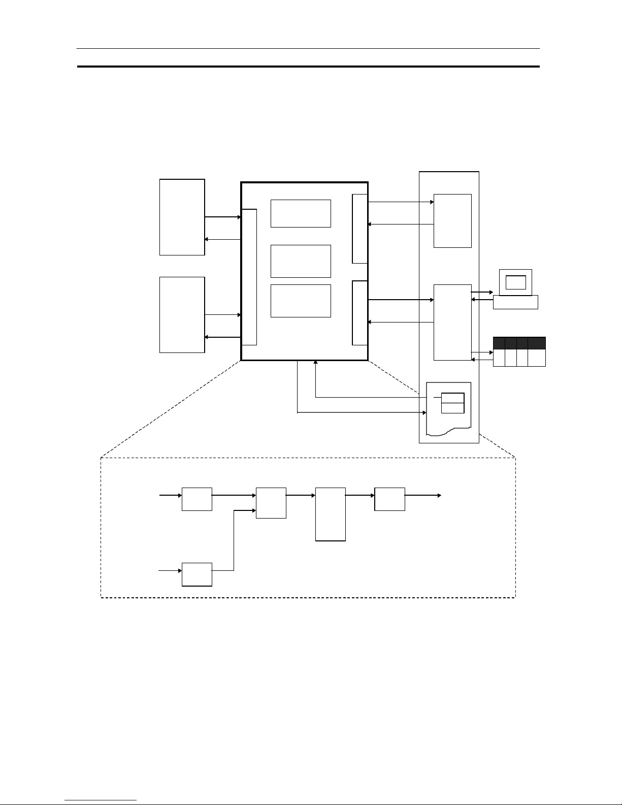
Overall Mechanism
The following illustration shows a block diagram of the overall mechanism.
Loop Control Unit
Control block
Operation bloc k
Step Ladder
Program bloc k
Fiel d Termin al s
CPU Termina lsNode Terminals
CPU Unit
I/O
memory
Analog
Input/Output Unit
Basic I/O Unit
Data
Memory
for No de
Terminals
Computer
Lo op Con tr ol Un it s a t
other node
CMND
User Program
Ex: Wi ring of ITEM
data in operati on
blocks using FINS
commands
Input 1 of Analog
Input Unit
Input 2 of Analog
Input Unit
Field Terminal
block
Analog
Input
Analog
input
Field Terminal
block
Addition
/Subtrac
-tion
Output of Anal og
Output Unit
Field Terminal
block
Analog
output
PID
Control block
All func tions are achieved by software wiring between any c om binations of functi on blocks.
Operation block
∗
1
∗
1
∗
1: Data is ex changed via
alloc at ed relay Area on
the CPU Unit
Page 30
Outline Section 1-1
10
The following describes each of the functions of the Loop Control Unit.
1) External I/O
WARNING
Do not perform writing operations on the same I/O memory address allocated
to contact outputs or analog outputs between the Loop Control Unit and the
CPU Unit.
If writing is performed on the same address, the externally connected load
may function unexpectedly, causing an injury.
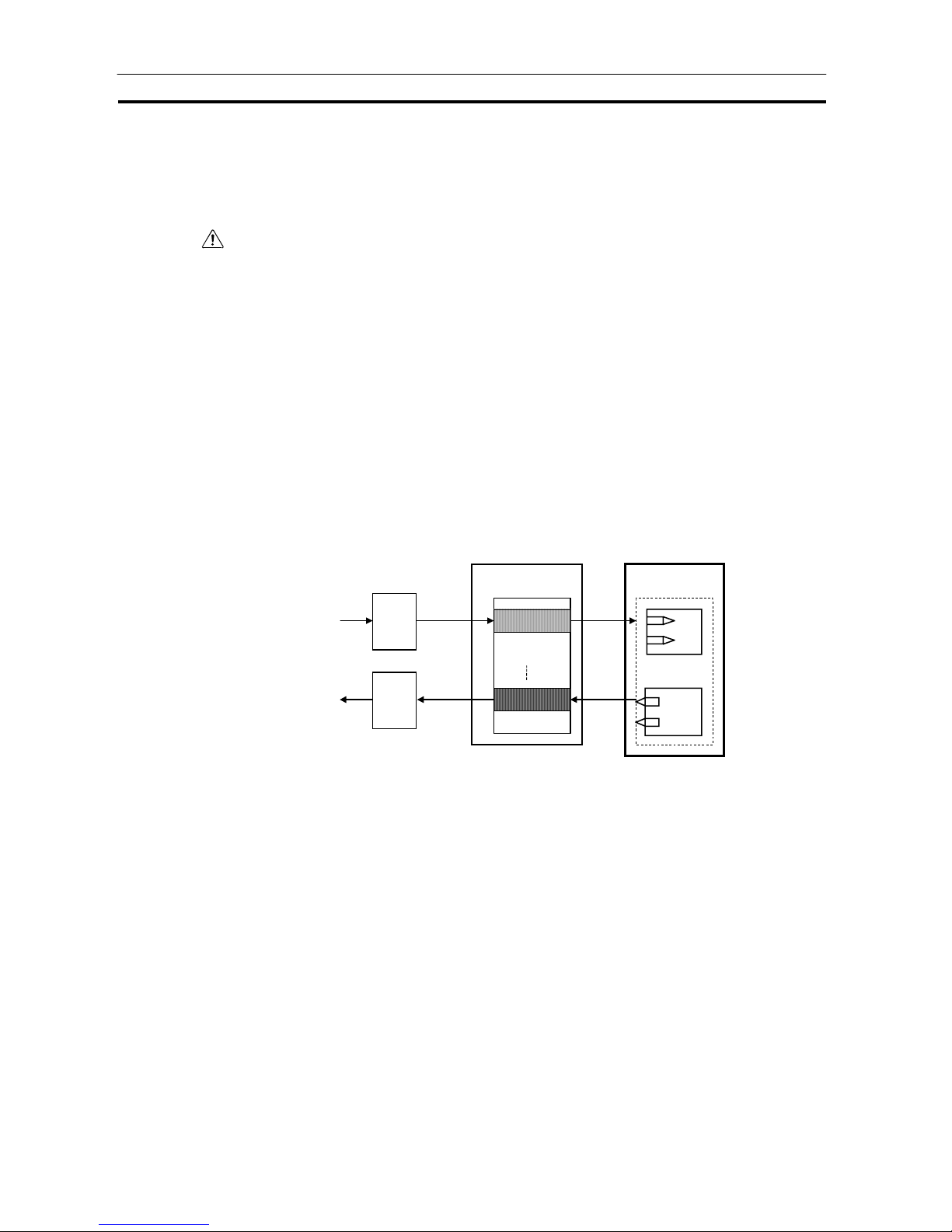
Analog I/O or Contact I/O
Analog signals or contact signals are input and output constantly (at each
operation cycle) between the Analog I/O Unit or Basic Unit on the same PC
and the CPU Unit I/O memory. At this time, the user is not required to be
aware of I/O memory addresses as the Field Terminal block is used.
With analog I/O, only the unit number of the Analog I/O Unit is set. With
contact I/O, however, the leading allocated address in I/O memory must be
set.
At each I/O
refresh
At each I/O
refresh
Analog Input Unit
CPU Unit
I/O memory
Loop Control Unit
Analog Output Unit
Field Terminal
block
At each
operation
cycle
At each
operation
cycle
Note The Loop Control Unit uses the Field Terminal block (regardless of the user
program on the CPU Unit) to read and write areas allocated for contact or
analog signals. So, do not perform write operations on the same allocated
areas between the Loop Control Unit and the CPU Unit.
Page 31

Outline Section 1-1
11
Data Exchange with Specified CPU Unit I/O Memory
I/O operations can be performed internally on the Loop Control Unit
constantly (at each operation cycle) with any specified CPU Unit I/O memory.
In this case, the CPU Unit Terminal block or the Expanded CPU Unit
Terminal block is used, and the I/O memory address must be specified.
Data exchange is possible with the following I/O memories:
- CIO (channel I/O) Area
- Work Area (W)
- Holding Area (H)
- Data Memory (D)
- Extended Data Memory (E) bank No. 0
Note 1 This function can also be used to designate units (CompoBus/D,
CompoBus/S and other Communications Units) on which field terminals are
not supported, and CPU Unit I/O memory (remote I/O allocated area, etc.) for
enabling I/O.
CPU Unit
I/O memory
Loop Control Unit
CPU Unit Terminal block
or Expanded CPU Unit
Terminal block
At each
operation
cycle
At each
operation
cycle
Note 2 The Loop Control Unit uses the CPU Unit Terminal block or the Expanded
CPU Unit Terminal block (regardless of the user program on the CPU Unit) to
read and write to specified CPU Unit I/O memory. So, do not perform write
operations on the same I/O memory addresses between the Loop Control
Unit and the CPU Unit.
Data Exchange with CX-Process Monitor
Loop Control Unit data can be exchanged with CX-Process Monitor. Data or
analog signals for controller use can be uploaded to CX-Process Monitor
running on a computer connected via the RS-232C interface or a network
such as Controller Link.
Data such as the Set Point Values can also be changed on CX-Process
Monitor.
There are two data exchange modes: on-demand mode and Data Link mode.
(For details, see 3-4 Exchanging Data with CX-Process Monitor/SCADA
Software and Other Nodes and Appendix-2 How to Use the Node Terminal
Blocks.)
Page 32

Outline Section 1-1
12
CPU Unit
Data Memory
for Node
Terminals
Loop Control Unit
Node Terminal
block
I/O memory
CX-Process Monitor
Uploading of
data to be
monitored
Manipulation of data
such as changes to
Set Point
At each
operation
cycle
Control block
PID, etc.
Data Exchange with SCADA Software
Commercially available SCADA software can also be used to read and write
function block data for the Loop Control Unit. Words in the I/O memory of the
CPU Unit are allocated for function block data so that Control Block,
Operation Block, and External Controller Block data can be read and written
using CSV tags with SCADA software. Expanded CPU Unit Terminal blocks
can also be used to read and write data using CSV tags for other ITEMs.
CSV tags are created using the CX-Process Tool.
Data Exchange with Loop Control Units at Other Nodes
Loop Control Unit data can be exchanged with Loop Control Units at other
nodes via Controller Link .
The following two methods can be selected.
1) When part of the data link is used (CPU Unit Terminal or Expanded
CPU Unit Terminal block)
CPU Unit
Specified words
Specified words
Words specifed
for Receive A ll
Blocks
Words specified
for Send All
Blocks
Loop Control Unit
Expansion CPU Unit
Terminals
Send All
Blocks
I/O memory
SCADA software
Set CSV tags
and read
Set CSV tags
and write
Set CSV tags
and write
Set CSV tags
and read
Control Block
ITEMs
Operation
Block ITEMs
External
Controller
Block ITEMs
Each
execution
cycle
Receive All
Blocks
Page 33

Outline Section 1-1
13
The PC on which the Loop Control Unit is mounted is linked via the regular
Controller Link Data Link with the PC at the other node. On this link, the Loop
Control Unit reads and writes analog signals or contact signals on part of the
Data Link Area on the CPU Unit by the CPU Unit Terminal or Expanded CPU
Unit Terminal block.
CPU Unit
Data Memory
for Node
Terminals
Loop Control Unit
CPU Unit Terminal or
Expanded CPU Unit
Terminal b lock
I/O memory
Loop Control Unit at
other node
Analog data or
contact data
At each
operation
cycle
At each
operation
cycle
Controller Link
Data Link
2) When Data Link Area 1 or 2 are occupied (Node Terminal block used)
The PC on which the Loop Control Unit is mounted occupies Data Link Area
1 or 2 for Loop Control Unit use, and is linked via the Controller Link Data
Link with the PC at the other node. Data Memory (D) for the Node Terminals
of the CPU Unit is allocated to Data Link Area. On this link, the Loop Control
Unit can exchange data with the other Loop Control Unit at the other node
PC by reading and writing Data Memory (D) for the Node Terminals of that
CPU Unit by the Node Terminal block.
CPU Unit
Data Memory
for Node
Terminals
Loop Control Unit
Node Terminal block
I/O mem ory
Loop Control Unit at
other node
Analog data or
contact data
At each
operation
cycle
Controller Link
Data Link is
occupied.
At each
operation
cycle
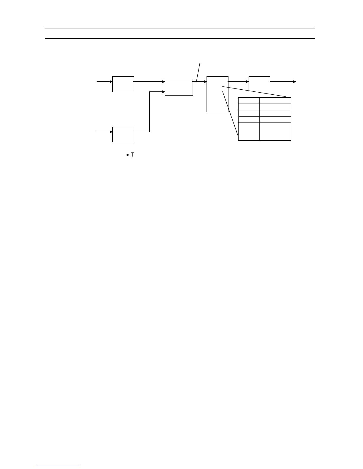
2) Internal processing
Prepare a data sheet for the function blocks shown below on CX-Process
Tool, and store the data sheet on the Loop Control Unit. The function block
data sheet describes: (a) software wiring of each function block and (b)
parameters in each function block.
Page 34
Outline Section 1-1
14
Fi el d Terminal
block
Analog
input
Analog
input
Field Terminal
block
Addition/
Subtraction
Fi el d Terminal bloc k
Analog
output
PID
Control blockOperat i on bl oc k
Software wirin g
ITEM Data
000
001
002
:
:
Parameters
The Loop Control Unit handles analog I/O signals not in engineering units
but in percentage units.
Example 1 At analog input, the converted values 0000 to 0FA0 (FF38 to 1068) Hex from
the Analog Input Unit for input 4 to 20 mA (3.2 to 20.8 mA) are converted to
0.00 to 100.00% (-5.00 to 105.00%) before they are processed by the Loop
Control Unit.
Example 2 At analog input, the converted values F830 to 07D0 (F768 to 0898) Hex from
the Analog Input Unit for input -10 to +10 mV (-11 to +11 V) are converted to
0.00 to 100.00% (-5.00 to 105.00%) before they are processed by the Loop
Control Unit.
Example 3 At analog output, the values 0.00 to 100.00% (-5.00 to 105.00%) are
converted to setting values 0000 to 0FA0 (FF38 to 1068) Hex before 4 to 20
mA (3.2 to 20.8 mA) is output from the Analog Output Unit.
Note Converted values (in the case of analog input) for 0 to 100% on the Loop
Control Unit and setting values (in the case of analog output) for 0 to 100%
on the Loop Control Unit are fixed to the same values as the user ranges.
However, in the case of isolated-type Analog Input Units (CS1WPTS01/02/03, PTW01, PDC01, PPS01, PTR01), the Analog Input Unit itself
has a range setting function. So, any values can be specified as the
converted values (on condition that the same setting as the range setting is
made).
Page 35

Outline Section 1-1
15
Likewise, data exchange with the CPU Unit is handled not in engineering
units but in percentage units. Values in I/O memory words are converted to
percentage units based upon the specified range before they are input to
the Loop Control Unit. Alternatively, percentage values are converted to
Hex values based upon the specified range before they are output to CPU
Unit I/O memory.
Example 1 At input from the CPU Unit, the values of 0000 to 0FA0 Hex in the I/O
memory words are converted to 0.00 to 100.00% before they are input to the
Loop Control Unit when the range 0 to 4000 (0000 to 0FA0 Hex) is specified.
Example 2 At output to the CPU Unit, the values of 0.00 to 100.00% are converted to
0000 to 0FA0 Hex before they are output to the Control Unit when the range
0 to 4000 (0000 to 0FA0 Hex) is specified.
Note 1 In data exchange with the CPU Unit, data can be actually exchanged within
the range -320.00 to +320.00% and not within the range 0.00 to 100.00%.
So, in the above example, the conversion range for 0 to 4000 (0000 to 0FA0
Hex) is 0.00 to +100.00. However, in actual operation, 8300 to FFFF Hex and
0000 to 7D00 Hex are converted to -320.00 to -0.01 and 0.00 to +320.00%,
respectively, before they are proces s ed.
Note 2 Any data range in CPU Unit I/O memory corresponding to 0 to 100% on the
Loop Control Unit can be specified. (The data range is dependent on the
specified input range and output range on the CPU Unit Terminal block or the
Expanded CPU Unit Terminal block.)
CX-Process Tool scales these percentage values to engineering units
values, and CX-Process Monitor monitors and sets the values in engineering
units. (For details, see 3-1 Configuration of Func tio n Bloc k s.)
Note 3 The Loop Control Unit does not process analog data in engineering units
(scaled values). (All analog data is processed in percentage values.) To
monitor/and set analog data in engineering units, the analog data must be
scaled on CX-Process Tool and then monitored and set on CX-Process
Monitor.
Page 36

Outline Section 1-1
16
1-1-6 Overall Mechanism of Data Exchange
The following block diagram shows the overall mechanism of data exchange.
Loop Control Unit at
other node
Analog/Basic I/O and other unitsLoop Control Unit
Square Root or
other Operation block
Analog I/O or other
External I/O (Field
Terminal) block
CPU Unit Terminal
block or Expanded
CPU Unit Terminal
block
PID or other Control
Block
CPU Unit
I/O memo ry
At each
execution of
block operation
Operation
cycle
Allocated area
At each I/O
refresh
Every 1 second
Allocated relays of
Analog Unit, etc.
Any area
At each
execution of
block operation
Allocated ar ea of
Loop Control Unit
Status
CMND
User program
I/O memo ry
FINS command
to Loop Control
Unit issued as
necessary
System Common
block
At each executio n
of block operation
Status
Data Memory
for Node
Terminals
Node Terminal block
CX-Process Monitor
Uploading of data to
be monitored
At each
execution of
block operati on
I/O memo ry
CX-Process Tool
Preparation of Function Block
Data
-1
-2
Step Ladder
Program block
Error log data
Data readable by
FINS command
CMND
User program
CX-Process
Monitor
Page 37

Outline Section 1-1
17
Function Block Operations (independent of and asynchronous with
CPU Unit)
The function blocks on the Loop Control Unit are cyclically executed
according to fixed operation cycles. Operations are executed asynchronously
with the user program on the CPU Unit.
The operation cycle is one of 0.1, 0.2, 0.5, 1 or 2 seconds (
1), and can be
specified to each function block. (The default operation cycle is one second
for each function block.)
Operation is started when the PC is turned ON regardless of the CPU Unit
operation mode.
1 The execution cycle for commands in the Step Ladder Program block
(Block Model 301) on the Loop Control Unit is one of 0.1, 0.2, 0.5, 1 or 2
seconds for each operation cycle in the Step Ladder Program block. The
command execution cycle is longer than the cycle time of commands in
the Step Ladder Program on the CPU Unit.
External I/O (via the CPU Unit I/O memory)
The Loop Control Unit actually updates external I/O data from each unit via
CPU Unit I/O memory at each operation cycle of the Field Terminal block.
Constant Data Exchange with CPU Unit (by Function block)
The Loop Control Unit refreshes data I/O with specified CPU Unit I/O
memory areas at each operation cycle of the CPU Unit Terminal block or the
Expanded CPU Unit Terminal block.
On-demand Data Exchange with CPU Unit (by FINS command
issued to Unit)
The CPU Unit can read and write Loop Control Unit data by issuing the FINS
command to the Loop Control Unit by the CMND (DELIVER COMMAND)
command in the Step Ladder Program whenever necessary.
CPU Unit Status Notification (by reflecting in System Common
block)
The status of the CPU Unit (operation mode, fatal error, etc.) is reflected in
the System Common block on the Loop Control Unit. If necessary, the Loop
Control Unit extracts data from this System Common block.
Loop Control Unit Status Notification (by allocated CIO Area)
The status of the Loop Control Unit is reflected on the CPU Unit at the CIO
Area allocated as the CPU Bus Unit. Note, however, that this status is
reflected every second and not at the I/O refresh cycle.
Page 38

Outline Section 1-1
18
Data Exchange with CX-Process Monitor and Loop Control Units at
Other Nodes (by Node Terminal block)
The Data Memory for node terminals is allocated to the CPU Unit Data
Memory area comprising the following two areas:
-1 Data exchange area with CX-Process Monitor
-2 Data exchange area with Loop Control Unit at other node
For either area, the Node Terminal block is used for performing data
exchange constantly (at each operation cycle) with CX-Process Monitor or
Loop Control Units at other nodes.
Reading of Error Log Data on Loop Control Unit
Error log data is stored on the Loop Control Unit. (The error code, detailed
information, date (year/month) and time (hour/minute/second) of occurrence
are recorded as one error log data record, and the latest 256 data records
are stored.) Error log data can be read using the read error log FINS
command (command code 2102 Hex).
Note Relationship between CPU Unit I/O Memory and Loop Control Unit
The Loop Control Unit can read from and write to CPU Unit I/O memory by
the methods indicated in the following table.
Purpose of data on Loop Control Unit
Data direction
Loop Control Unit
CPU Unit
Loop Control Unit
CPU Unit
Loop Control Unit
CPU Unit
Loop Control Unit
CPU Unit
I/O memory area
type on CPU Unit
Reading or writing
at CPU Unit
Terminals,
Expanded CPU
Unit Terminals, or
Send/Receive All
Blocks
: possible,
: impossible
Reading or writing
at field terminals
Writing at data
memory for node
terminals
Writing using
allocated area for
CPU Bus Unit
CIO
Reading/writing of
CIO area on
corresponding
unit at field
terminals
Notification of
Loop Control Unit
status
Work Area (W)
Holding Area (H)
Auxiliary Area
Temporary Relay
Area
Tmer
Counter
Data Memory
Area (D)
Up to 3836 words
allocated for use
for CX-Process
Monitor
Extended Data
Memory Area (E)
(bank No.0
only)
Page 39
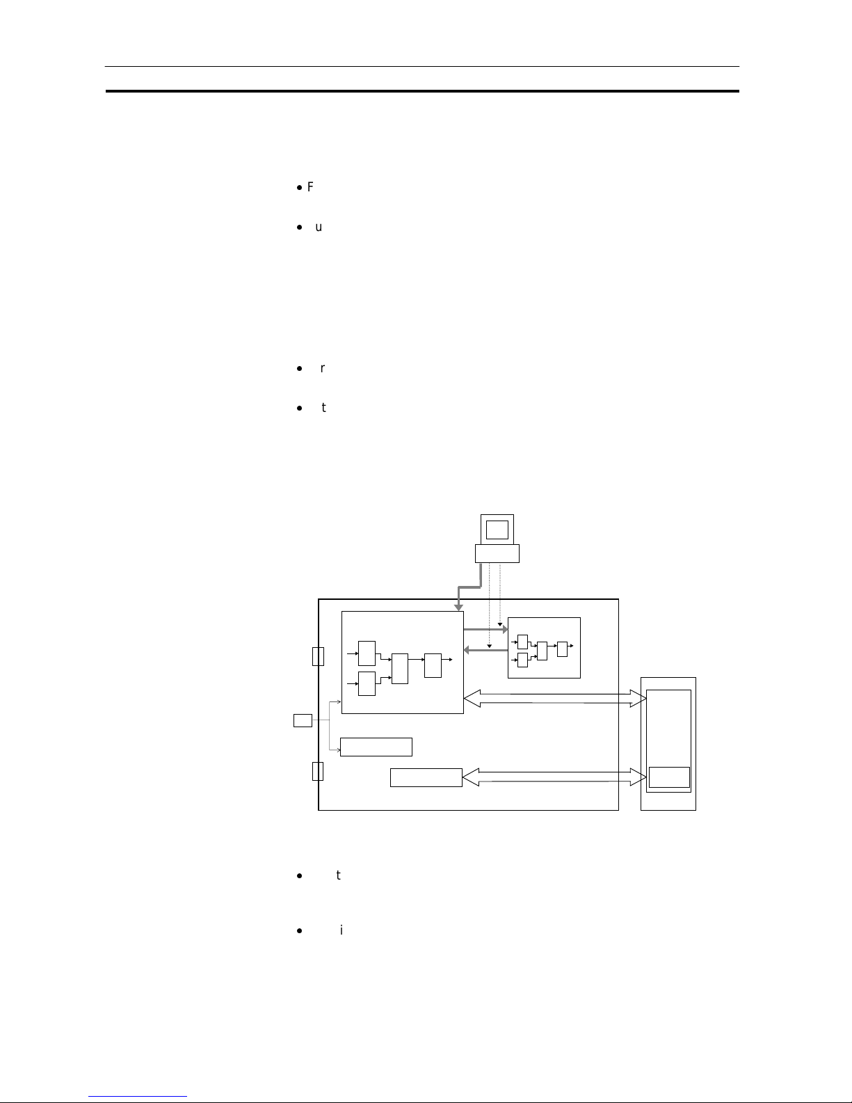
Outline Section 1-1
19
1-1-7 Internal Mechanism of Loop Control Uni t
The following describes the internal mechanism of the Loop Control Unit.
Function block data and error log data are backed up by internal battery in
RAM. During actual operation, the Loop Control Unit used the data in RAM.
Function block data is prepared and downloaded to RAM in the Loop
Control Unit from CX-Process Tool running on the computer.
From the CX-Process Tool, you can transfer data between RAM and flash
memory whenever necessary, or you can set the Loop Controller Unit to
automatically transfer the contents of flash memory to RAM whenever
power is turned ON. This enables operation without a backup battery.
(Error log data, however, is not backed up without a battery, i.e., it is not
store in flash memory.)
Error log data can be read using the READ ERROR LOG FINS command
(command code 2102 Hex). Error log data is not stored in flash memory.
In the default state, function block data is not stored on the Loop Control
Unit. Function block data must be downloaded from a computer before the
Loop Control Unit can be run.
Set whether or not to
transfer flash memory
contents to RAM at
startup.
I/O memory
Flash memory
RAM
Recover
Command
Download
The contents of RAM an d flash
memory can be transferred back
and forth as requried.
DIP switch
Function block data
Back up
CPU Unit
Function block data prepared and
downl o aded to RAM fro m CX-P rocess Tool
Loop Control Unit
Function block data sheet
(all function block data)
Stored error log data
Batter
Backup
Unit address
settin g switch
(front panel)
At each operation execution
Every 1 second
Alloca ted data
Allocated
words
Note:
Function block data in RAM can be backed up to flash memory using the
CX-Process Tool. Refer to the CX-Process Tool Operation Manual for
details.
Function block data in flash memory can be restored to RAM. This can be
achieved either automatically at startup (set by turning ON pin 2 of the DIP
switch) or by using the CX-Process Tool. The use of the DIP switch is
described later in this manual. Refer to the CX-Process Tool Operation
Manual for details on using the CX-Process Tool.
Page 40

Outline Section 1-1
20
1-1-8 List of Function Blocks
The following function blocks are combined and used in Loop Control Units.
Category Type
Block
model
Block name Function
Allocatable
block
address
System
Common
Block
System
Common
Block
000 System
Common
Makes settings common to all function blocks and
outputs signals for the system.
000
001 2-position
ON/OFF
2-position type ON/OFF controller
002 3-position
ON/OFF
3-position type ON/OFF controller for heating/cooling
ON/OFF control
011 Basic PID Performs basic PID control.
012 Advanced PID Performs PID with two degrees of freedom control for
enabling deviation/MV compensation, MV tracking,
etc.
013 Blended PID Performs PIF control on the cumulative value
(cumulative deviation) between the accumulated value
PV and accumulated value Remote Set Point.
014 Batch Flowrate
Capture
Functions to open the valve at a fixed opening until a
fixed batch accumulated value is reached.
016 Fuzzy Logic
Inputs up to eight analog inputs and then outputs up
to two analog outputs based on fuzzy inferences.
031 Indication and
Setting
Manual setter with PV indication and and SP setting
functions
032 Indication and
Operation
Manual setter with PV indication and MV setting
functions
033 Ratio Setting Ratio and bias setter with PV indication and ratio
setting function
Control
Block
Controller
034 Indicator PV indicator with PV alarm
001 to 032
External
Controller
Block
External
Controller
Block
045 ES100X
Controller
Terminal
Performs monitoring and setting for an ES100X
Controller connected directly to the RS-232C port on
the Loop Control Unit.
065 to 096
110
4-Point Warning
Indicator
Provides the alarm contact outputs for the high/high,
high, low, and low/low limits of single analog signals.
This function block provides the same function as the
Indicator block (model 034).
111 High/Low Alarm Provides the alarm contact outputs for the high and
low limits of single analog signals.
112 Deviation Alarm Provides the alarm contact outputs for the deviation of
two analog signals.
113 Rate-of-change
Operation and
Alarm
Provides the alarm contact outputs for the high and
low limits of rate-of-change operation when the analog
signal rate-of-change is output.
115 High/Low Limit Limits the high and low limits of single analog signals.
116 Deviation Limit Calculates the deviation between two analog signals,
and limits the deviation within that range.
Alarm/Signal
restrictions/
Hold
118 Analog Signal
Hold
Holds the maximum, minimum or inst anta neou s val ue
of single analog signals.
121 Addition or
Subtraction
Performs addition/subtraction with gain and bias on up
to 4 analog signals.
122 Multiplication Performs multiplication with gain and bias on up to 2
analog signals.
123 Division Performs division with gain and bias on up to 2 analog
signals.
126 Arithmetic
Operation
Performs various math operation (trigonometric.
logorithmic, etc.) on floating-point decimal values
converted (to industrial units) from up to 8 analog
inputs.
Operation
Block
Arithmetic
127 Range
Conversion
Converts analog ranges for up to eight analog signals
based only on values input for 0% and 100% inputs
and 0% and 100% outputs.
100 to 349
(Note: 349
is an
internal
switch in
CXProcess
Tool (One
Block
Model 209
is already
allocated
as the
default.))
Page 41

Outline Section 1-1
21
Category Type
Block
model
Block name Function
Allocatable
block
address
131 Square Root Performs square root extraction (with low-end
cutout) on single analog signals.
132 Absolute Value Performs non-linear (3 gain values) operation on
single analog signals. Analog signa ls can al so set as
a dead band (with different gap).
133 Non-linear Gain
(Dead Band)
Outputs the absolute value of single analog signals.
134 Low-end Cutout Sets output to zero close to the zero point of single
analog signals.
135 Segment
Linearizer
Converts single analog sigals to 15 segments before
the signals is output.
Functions
136 Temperature And
Pressure
Correction
Performs temperature and pressure correction.
Operation
Block
(continued)
141 First-order Lag Performs first-order lag operation on single analog
signals.
143 Rate-of-change
Limit
Performs rate-of-change restriction on sing le anal og
signals.
145 Moving Average Performs moving average operation on single
analog signals.
147 Lead/Delay
Performs lead/delay operation on single analog
signals.
100 to 349
(Note: 349
is an
internal
switch in
CXProcess
Tool (One
Block
Model 209
is already
allocated
as the
default.))
148 Dead Time Performs dead time and first-order lag operations on
single analog signals.
149 Dead Time
Compensation
Used for Smith’s dead time compensation PID
control
150 Accumulator for
instantaneous
value input
Accumulates analog signals, and outputs 8-digit
accumulated value signals.
151 CPU Unit Running
Time Accu mulator
Accumulates the operating time, and outputs the
pulse signal per specified time.
153 Time Sequence
Data Statistics
Records time sequence data from analog signals
and calculates statistics, such as averages and
standard deviations.
155 Ramp Program Ramp program setter for combining ramps for time
and hold values.
156 Segment Program Segment program setter setting the output values
with respect to time.
Time
Function
157 Segment Program2Segment program setting with wait function for
setting the output values with respect to time
161 Rank Selector Selects the rank of up to 8 analog signals.
162 Input Selector Selects the specified analog signals specified by the
contact signal from up to 8 analog signals.
163 3-input Selector Selects and outputs one of three analog input
signals.
164 3-output Selector Outputs one analog input signal in three switched
direction.
165 Constant Selector Selects 8 preset constants by the contact signal.
166 Constant
Generator
Outputs 8 independent constants.
Signal
Selection/
Switching
167 Ramped Switch
Creates a ramped switch based on two analog
inputs or constants.
171 Constant ITEM
Setting
Writes the constant to the specified ITEM at the
rising edge of the send command contact.
172 Variable ITEM
Setting
Writes the analog signal to the specified ITEM at the
rising edge of the send command contact.
174 Batch Data
Collector
Stores each of max. 8 analog inputs to buffer by a
certain timing within sequential processing.
182 Accumulated
Value Input Adder
Adds up to four accumulated value signals.
ITEM
Settings
183 Accumulated
Value Analog
Multiplier
Multiplies analog signals by the accumulated value
signals.
Page 42
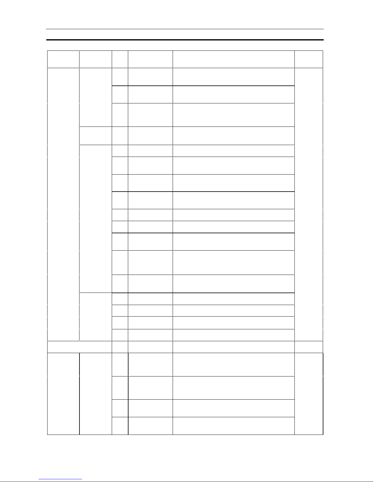
Outline Section 1-1
22
Category Type
Block
model
Block name Function
Allocatable
block
address
184 Accumulator for
accumulated value
input
Converts 4-digit accumulated value signals to 8
digits.
185 Contact
input/Accumulated
value output
Counts low-speed contact pulses, and outputs 8-
digit accumulated signals.
Operation
Block
(continued)
Pulse Train
Operation
186 Accumulated
Value
Input/Contact
Output
Converts 4-digit accumulated value signals to low-
speed contact pulses before they are output.
Others 192 Analog/Pulse
Width Converter
Changes the ON/OFF duration ratio in a constant
cycle duration so that it is proportional to the analog
signal.
201 Contact Distributor Connect contact signals between function blocks in
a 1:1 connection.
202 Constant
Comparator
Compares up to eight sets of analog signals and
constants, and outputs the compariso n result s as
contacts.
203 Variable
Comparator
Compares up to eight pairs of analog signals, and
outputs the comparison results as contacts.
205 Timer 2-stage output-type addition timer for forecast
values and reached values. Can also output the
present value.
100 to 349
(Note: 349
is an
internal
switch in
CXProcess
Tool (One
Block
Model 209
is already
allocated
as the
default.))
206 ON/OFF Timer Timer for performing ON-OFF operation at preset
ON and OFF times.
207 Clock Pulse Outputs clock pulses that turn ON for one operation
cycle only at each set time.
208 Counter 2-stage output type addition timer for forecast values
and arrival values. Can also output the current
value.
209 Internal Switch
Temporary storage contact for accepting relays in
the Step Ladder Program block.
(Note: One internal switch is already allocated as
"temporary storage" in CX-Process Tool.)
Sequence
Operation
210 Level Check
Checks the level of an analog input for eight levels
and outputs contacts according to the level. The
level number is also output via an analog output.
221 ON/OFF Valve
Manipulator
Manipulates and monitors ON/OFF valves with
open/close limit switches.
222 Motor Manipulator Manipulates and monitors motor operation.
223 Reversible Motor
Manipulator
Manipulates and monitors reversible motor
operation.
Contact Type
Control
Target
224 Motor Opening
Manipulator
Inputs a target opening, and manipulates an electric
positional-proportional motor .
Sequential Control 301 Step Ladder
Program
Performs logic sequence and step progression
control.
400 to 499
Node
Terminal
401 DO to Computer Sends 128 contacts to the send-to-computer area.
When CX-Process Monitor is used, the contac t
signals to be monitored are connected to this
function block.
501 to 532
402 AO to Computer Sends 16 analog values to the send-to-computer
area. When CX-Process Monitor is used, the analog
signals to be monitored are connected to this
function block.
403 1-Block Send
Terminal to
Computer
Sends a specified 1 block to the send-to-computer
area. When CX-Process Monitor is used, the 1 block
to be monitored are connected to this function block.
Send to
Computer
404 4-Block Send
Terminal to
Computer
Sends a specified 4 block to the send-to-computer
area. When CX-Process Monitor is used, the 4 block
to be monitored are connected to this function block.
Page 43

Outline Section 1-1
23
Category Type
Block
model
Block name Function
Allocatable
block
address
407 DO Terminal to
all nodes
Sends 32 contacts to nodes on the Controller Link
Data Link.
550 to 599
Send to All
Nodes
408 AO Terminal to
all nodes
Sends 2 analog values to nodes on the Controller Link
Data Link.
409 DO Terminal
Settings from
Computer
Receives 32 contacts sent from the computer. (Can
also be downloaded to the send-to-all nodes area.)
Send to All
Nodes
410 AO Terminal
Settings from
Computer
Receives 2 analog values sent from the computer.
(Can also be downloaded to the send-to-all nodes
area.)
550 to 599
Node
Terminal,
continued
Receive from
All Nodes
414 DI Terminal from
all nodes
Receives 32 contacts sent from nodes on the
Controller Link Data Link.
600 to 699
Node
Terminal
(continued)
Receive from
All Nodes
(continued)
415 AI Terminal from
all nodes
Receives 2 analog values sent from nodes on the
Controller Link Data Link.
451 DI Terminal from
CPU Unit
Inputs max. 128 points from any leading address in
CPU Unit I/O memory (one of CIO, WR, HR, DM and
EM area types). (read)
452 DO Terminal to
CPU Unit
Outputs max. 128 points from any leading address in
CPU Unit I/O memory (one of CIO, WR, HR, DM and
EM area types). (read and write)
453 AI Terminal from
CPU Unit
Inputs max. 8 words from any leading address in CPU
Unit I/O memory (one of CIO, WR, HR, DM and EM
area types). (read)
CPU Unit Terminal
454 AO Terminal to
CPU Unit
Outputs max. 8 words from any leading address in
CPU Unit I/O memory (one of CIO, WR, HR, DM and
EM area types). (read and write)
861 to 876
455 Expanded DI
Terminal from
CPU Unit
Inputs any contact data in CPU Unit I/O Memory, and
writes max. 64 points on another function block.
456 Expanded DO
Terminal from
CPU Unit
Inputs the contact data of another function block, and
writes max. 64 points on any I/O Memory in the CPU
Unit.
457 Expanded AI
Terminal from
CPU Unit
Inputs any analog data in CPU Unit I/O Memory, and
writes max. 64 words on another function block.
Expanded
CPU Unit
Terminal
458 Expanded AO
Terminal from
CPU Unit
Inputs the analog data of another function block, and
writes max. 64 words on any CPU Unit I/O Memory.
829 to 860
461 Receive All
Blocks
Reads ITEM data specified for Send/ Receive All
Blocks for up to 32 Control Blocks, 249 Operation
Blocks, and 32 External Controller Blocks starting
from a specified address in the I/O memory of the
CPU Unit.
897
SCADA
Interface
Send/
Receive All
Blocks
462 Send All Blocks Writes ITEM data specified for Send/ Receive All
Blocks for up to 32 Control Blocks, 249 Operation
Blocks, and 32 External Controller Blocks starting to a
specified address in the I/O memory of the CPU Unit.
898
Page 44

Outline Section 1-1
24
Category Type
Block
model
Block name Function
Allocatable
block
address
501 DI 8-point
Terminal
Inputs 8 contacts from 8-point Input Unit.
502 DI 16-point
Terminal
Inputs 16 contacts from 16-point Input Unit.
503 DI 32-point
Terminal
Inputs 32 contacts from 32-point Input Unit.
504 DI 64-point
Terminal
Inputs 64 contacts from 64-point Input Unit.
511 DO 5-point
Terminal
Outputs 5 contacts from 5-point Output Unit.
512 DO 8-point
Terminal
Outputs 8 contacts from 8-point Output Unit.
513 DO12-point
Terminal
Outputs 12 contacts from 12-point Output Unit.
514 DO16-point
Terminal
Outputs 16 contacts from 16-point Output Unit.
515 DO32-point
Terminal
Outputs 32 contacts from 32-point Output Unit.
516 DO64-point
Terminal
Outputs 64 contacts from 64-point Output Unit.
518 DI 16-
point/Do16-point
Terminal
Inputs and outputs 16 contacts each from 16-point
Input/16-point Output Unit.
588 Ai4 Terminal
(DRT1-AD04)
Inputs 4 analog inputs from a DRT1-AD04 Analog
Input Unit (a DeviceNet slave).
Field
Terminal
Contact I/O
589 Ao2 Terminal
(DRT1-DA02)
Outputs 2 analog outputs from the field outputs
on a
DRT1-DA04 Analog Output Unit (a DeviceNet
slave).
901 to 980
Page 45

Outline Section 1-1
25
Category Type
Block
model
Block name Function
Allocatable
block
address
525 DI 96-point
Terminal
Inputs 96 contacts from 96-contact Input Unit.
537 DO 96-point
Terminal
Outputs 96 contacts from 96-contact Output
Unit.
Contact I/O
544 DI 48-point/DO
48-point
Terminal
Inputs and outputs 48 contacts each from 48point Input/48-point Output Units.
551 AI 8-point
Terminal
(AD003)
Inputs 8 analog signals from the C200HAD003.
552 AO 8-point
Terminal
(DA003/4)
Inputs 8 analog signals from the C200HDA003/DA003.
Analog I/O
553 AI 2-point/AO 2-
point Terminal
(MAD01)
Inputs and outputs 2 analog signals each
from the C200H-MAD01.
561 AI 4-point
Terminal
(PTS01/02/03,P
DC01,PTW01)
Inputs 4 analog signals from one of CS1WPTS01 (Isolated-type Thermocouple Input
Unit), CS1W-PTS02/03 (Isolated-type
Temperature-resistance Thermometer Input
Unit), CS1W-PDC01 (Isolated-type Analog
Input Unit) or CS1W-PTW01 (2-lead
Transmitter Input Unit).
562 PI 4-point
Terminal
(PPS01)
Inputs 4 instantaneous values and
accumulated values each from CS1W-PPS01
(Isolated-type Pulse Input Unit).
563 AO 4-point
Terminal
(PMV01)
Outputs 4 analog signals from CS1W-PMV01
(Isolated-type Control Output Unit).
564 AI 8-point
Terminal
(PTR01/02)
Inputs 8 analog signals from CS1W-PTR01
(Power Transducer Input Unit) or CS1WPTR02 (Analog Input Unit (100 mV)).
583 AI 4-point/AO 4-
point Terminal
(MAD44)
Inputs and outputs 4 analog signals each
from the CS1W-MAD44.
584 AI 8-point
Terminal
(AD081)
Inputs 8 analog signals from the CS1WAD081.
585 AO 8-point
Terminal
(DA08V/C)
Outputs 8 analog signals from the CS1WDA08V/C.
586 AI 4-point
Terminal
(AD041)
Inputs 4 analog signals from the CS1WAD041.
Field Terminal
Analog I/O
587 AO 4-point
Terminal
(DA041)
Outputs 4 analog signals from the CS1WDA041.
901 to 980
Page 46

Configuration of Instrumentation System Section 1-2
26
1-2 Configuration of Instrumentation System
1-2-1 Mounting Location
The Loop Control Unit CS1W-LC001 is a CPU Bus Unit for the CS1 Series.
Up to three Loop Control Units can be mounted on the CPU Rack for the
CS1 Series CPU Unit at any of the positions indicated in the figure below.
Note The Loop Control Unit cannot be mounted on the Expansion Rack for the
CS1 Series, the Expansion I/O Rack for the C200H and SYSMAC BUS
Remote I/O Slave Rack.
Up to three units can be mounted at
any of these three positions.
CPU Rack
CPU Unit
Mountable CPU Unit Models
PC Series CPU Unit model Max. number of
Units mountable
on CPU Rack
Mounting position
restrictions
CS1 CS1H-CPU
CS1G-CPU
Three units
(unit No.0 to F)
None
Page 47

Configuration of Instrumentation System Section 1-2
27
1-2-2 Determining the System Configuration
Check the following points when determining the system configuration:
1, 2, 3… 1. Number of Analog I/O Points Used on Loop Control Unit
Which analog signals are input/output on the AI/AO terminals of the Field
Terminal block, and which analog signals are input/output on the CPU
Unit Terminal block or the Expanded CPU Unit Terminal block?
The total number of usable AI/AO terminals on the Field Terminal block
combined with the DO/DI terminals is 80. (For details of the unit types
that can be used, see page 30.)
The maximum number of usable CPU Unit Terminal blocks is 16. (For
details of I/O memory area that can be specified, see page 31.)
2. Number of Contact I/O Points Used on Loop Control Unit
Which contact signals are input/output on the DI/DO terminals of the
Field Terminal block, and which contact signals are input/output on the
CPU Unit Terminal block or the Expanded CPU Unit Terminal block?
The total number of DI/DO terminals on the Field Terminal block
combined with the AO/AI terminals is 80. (For details of the unit types
that can be used, see page 33.)
The maximum number of usable CPU Unit Terminal blocks is 16. (For
details of I/O memory area that can be specified, see page 33.)
3. Current Consumption
Is the current consumption of the units mounted on the rack less than the
current consumption of the Power Supply Unit?
Refer to CS1-series Operation Manual (Catalog No. W33 9-E1), 2-6 Unit
Current Consumption.
4. Evaluation of Load Rate
The Loop Control Unit cyclically processes operation of its own function
blocks asynchronously with I/O refreshing of the CPU Unit. The cycle by
which operations are processed, or the "operation cycle," is dependent
on the type and number of function blocks used.
For this reason, when many function blocks whose operation takes a long
time to process are used, the actual operation cycle of the entire Loop
Control Unit or an individual function block increases. As a result, the
desired preset operation cycle sometimes cannot be satisfied.
The ratio between the actual execution time required for processing
operation and the preset operation cycle is called the "load rate." The
maximum values and current value of each operation cycle group can be
confirmed on CX-Process Tool.
A load rate of 60% or less is required in all operation cycle groups on this
Loop Control Unit.
Page 48

Configuration of Instrumentation System Section 1-2
28
Note Running of the Loop Control Unit is automatically stopped when the operation
cycle of all function blocks is set to two seconds, and the load rate
continuously exceeds 70% for ten times. When this happens, processing of
the function blocks must be distributed across the Loop Control Units.
Use the following formula as a general guideline for estimating the load
rate of the Loop Control Unit at the system design stage.
How to Calculate the Load Rate
Calculate the load rate based upon the following formula.
When all operation cycles are the same operation cycle, the load rate is as
shown below. This, however, is to be used only as a guideline.
Formula
Load rate
Sum (ms) of operation execution times of each function block
operation cycle (ms) x 100 + fixed load rate (%)
Note 1 The following table shows the fixed load rates for each operation cycle:
Operation cycle Fixed load rate
0.1 sec 10%
0.2 sec 5%
0.5 sec 2%
1 sec 1%
2 sec 0%
Note 2 The "sum (ms) of operation execution times of each function block" is a value
obtained by discarding values less than 10 ms from the total time obtained by
adding the "operation execution time of the function blocks" to the "execution
time of the sequence commands."
Note 3 For details on the load rate, see 3-2 Description of Operations. For details on
the operation execution times for each function block and each of the
sequence commands in the Step Ladder Program block, see Appendix-4 List
of Operation Execution Times.
5. Evaluation of External I/O Refresh Cycle (dependent on CPU Unit’s
cycle time)
The operating speed (operation cycle) itself of each function block on the
Loop Control Unit is not related to the CPU Unit’s cycle time. However,
as the CPU Unit’s I/O memory is accessed during data exchange, for
example, between Analog I/O Units and the Basic I/O Unit, the timing of
data exchange is influenced by the CPU Unit’s cycle time.
The external analog I/O refresh cycle (equivalent to the I/O refresh cycle
on a general controller) when the Loop Control Unit is configured as part
of an instrumentation system is not the same as the operation cycle of
the function blocks; but is a cycle heavily dependent on the CPU Unit’s
cycle time.
Page 49

Configuration of Instrumentation System Section 1-2
29
In most cases, the maximum external analog I/O refresh cycle is as
follows depending on the operation timing:
"approximately 5 times the CPU Unit’s cycle time" + "approximately twice
the operation cycles of the Loop Control Unit’s function blocks"
So, when determining the system configuration, calculate how long the
external analog I/O refresh cycle will be within the instrumentation system
based upon factors such as the CPU Unit’s cycle time and the operation
cycles of the Loop Control Unit’s function blocks. Also, assess whether or
not there will be any problems when running applications at the analog
I/O refresh cycle that you have calculated.
(For details on the relationship between the Loop Control Unit’s operation
cycles and the CPU Unit’s cycle time, see 3-2 Description of Operations.
For details on how to calculate the CPU Unit’s cycle time, refer to the
CS1-series Operation Manual (W339-E1), 15-4 Computing the Cycle
Time.)
1-2-3 Description of Basic System Configuration
Mounting of Units for External Analog I/O and Contact I/O
The Loop Control Unit does not have direct external analog I/O and contact
I/O functions. External I/O is achieved via Analog I/O Units and Basic I/O
Units mounted on a basic PC System (CPU Rack, Expansion Rack for the
CS1, Expansion I/O Rack for the C200H) or on a SYSMAC BUS Remote I/O
Slave Rack.
So, in the basic system configuration, Analog I/O Units (Analog Input Unit,
Analog Output Unit, and Analog I/O Unit) must be mounted for the same PC.
A Basic I/O Unit must also be mounted for the same PC as necessary.
Page 50

Configuration of Instrumentation System Section 1-2
30
Input and Output of Analog Data
(1) When exchanging data without specifying the I/O memory address
(on Field Terminal block)
The table below shows the Units with which the Loop Control Unit can
exchange data regardless of I/O memory address. In data exchange with
these Units, use the AI Terminal or AO Terminal blocks on the Field Terminal
block that corresponds to the required Unit model as the Loop Control Unit’s
function blocks.
On the AI Terminal and AO Terminal blocks, set the unit number of the
Analog I/O Unit to enable input/output of analog signals.
Unit information Name Model Specification Function block
C200H Special
I/O Unit
Analog Input Unit C200H-AD003 8 analog inputs AI 8-point Terminal
(Block Model 551)
Analog Output
Unit
C200H-DA003/004 8 analog outputs AO 8-point Terminal
(Block Model 552)
Analog
Input/Output Unit
C200H-MAD01 2 analog inputs/2
analog outputs
AI 2-point/AO 2-
point Terminal
(Block Model 553)
CS1 Special
I/O Unit
Analog
Input/Output Unit
CS1W-MAD44 4 analog inputs/4
analog outputs
AI 4-point/AO 4-
point Terminal
(Block Model 583)
CS1W-AD081 8 analog inputs AI 8-point Terminal
(Block Model 584)
Analog Input Unit
CS1W-AD041 4 analog inputs AI 4-point Terminal
(Block Model 586)
CS1W-DA08V/C 8 analog outputs AO 8-point Terminal
(Block Model 585)
Analog Output
Unit
CS1W-DA041 4 analog outputs AO 4-point Terminal
(Block Model 587)
Isolated-type
Thermocouple
Input Unit
CS1W-PTS01 4 thermocouple
inputs
AI 4-point Terminal
(Block Model 561)
Isolated-type
Temperatureresistance
Thermometer
Input Unit
CS1W-PTS02/03 4 temperature-
resistance
thermometer inputs
2-lead Transmitter
Input Unit
CS1W-PTW01 4 2-lead transmitter
inputs
Isolated-type
Analog Input Unit
CS1W-PDC01 4 analog inputs
Isolated-type
Pulse Input Unit
CS1W-PPS01 4 pulse inputs PI 4-point Terminal
(Block Model 562)
Isolated-type
Analog Output
Unit
CS1W-PMV01 4 analog outputs AO 4-point Terminal
(Block Model 563)
Power Transducer
Input Unit
CS1W-PTR01 8 power transducer
inputs
AI 8-point Terminal
(Block Model 564)
Analog Input Unit
(100 mV)
CS1W-PTR002 8 analog inputs
Page 51

Configuration of Instrumentation System Section 1-2
31
Note 1 In the case of an analog output Field Terminal block, select the function block
according to the Unit model.
Note 2 In data exchange above, the Loop Control Unit handles analog I/O signals
not in engineering units but in percentage units. For example, the data 0000
to 0F0A (FF38 to 1068) Hex from the Analog Input Unit for input 4 to 20 mA
(3.2 to 20.8 mA) are converted to 0.00 to 100.00 (-5.00 to 105.00) % before
they are processed by the Loop Control Unit.
These percentage unit values are scaled to engineering units values by CXProcess Monitor.
WARNING When the Field Terminal block is used for analog I/O, the unit number set on
the Field Terminal block must match the unit number set on the Analog I/O
Unit front panel. Otherwise, input/output (read/write) operations will be
performed by mistake on the data of another Special I/O Unit (having the unit
number set on the field terminals).
(2) When exchanging data with a specified I/O memory address (on
CPU Unit Terminal block or the Expanded CPU Unit Terminal block)
When the Loop Control Unit exchanges analog data with a specified I/O
memory address, use the AI Terminal from CPU Unit and AO Terminal to
CPU Unit blocks on the CPU Unit Terminal block or the Expanded AI
Terminal from CPU Unit and Expanded AO Terminal to CPU Unit on the
Expanded CPU Unit Terminal block.
In this instance, the Loop Control Unit can exchange data with any type of
unit as long as the data is allocated to the I/O memory addresses indicated in
the following table. (For example, data on analog terminals allocated to the
CompoBus/D Area can also be exchanged.)
The following table shows I/O memory that can be specified on CPU Unit
Terminals or the Expanded AI Terminal from CPU Unit or Expanded AO
Terminal from CPU Unit in the Extended CPU Unit block:
Area type I/O memory address of CS1
CPU Unit
Remarks
CIO (channel
I/O) Area
0000 to 6143 words Including I/O Area,
CompoBus/D Area, Data Link
Area, and Special I/O Unit Area
(*1)
Work Ar ea (W) W000 to 511 words
Holding Area (H) H000 to 511 words
Data Memory (D) D00000 to 32767 (words) Including Special I/O Unit Area
in Data Memory Area
Extended Data
Memory (E) bank
No.0
E0_00000 to E0_32767
The following CPU Unit Terminal function blocks or the Expanded CPU Unit
Terminal block are used:
Number of points Function block
8 words AI Terminal from CPU Unit (Block Model 453)Input
64 words Expanded AI Terminal from CPU Unit (Block Model 457)
8 words AO Terminal to CPU Unit (Block Model 454)Output
64 words Expanded AO Terminal from CPU Unit (Block Model 458)
Page 52

Configuration of Instrumentation System Section 1-2
32
Note 1 In addition to the above number of points, the CPU Unit Terminal block differs
from the Expanded CPU Unit block as follows:
With the CPU Unit Terminal block, analog output to another function block
must go via the Variable ITEM Setting block (Block Model 172). Whereas,
with the Expanded CPU Unit Terminal block, analog output can be output
directly without going via the Variable ITEM Setting block (Block Model 172).
Also, with the CPU Unit Terminal block, analog input/output to and from
another function block is possible from only either "analog input" or "analog
output" type ITEMs. Whereas, with the Extended CPU Unit Terminal block,
input/output is also possible from all ITEMs (mainly parameter ITEMs) that
can be written by the Variable ITEM Setting block (Block Model 172) in
addition to the above ITEMs for the CPU Unit Terminal block.
Note 2
In data exchange above, the AI Terminal from CPU Unit block or Expanded
AI Terminal from CPU Unit treats data in the words as decimal data, and
specifies which values are to be converted to 0% and 100% values for any
specified range. For example, when the range 0 to 4000 (0000 to 0FA0
Hex) is specified for input from the CPU Unit, the AI Terminal from CPU
Unit block converts the values of 0000 to 0FA0 Hex in I/O memory words to
0.00 to 100.00% before inputting them to the Loop Control Unit.
Alternatively, the AO Terminal to CPU Unit block or AO Terminal to
Expanded CPU Unit can specify the target conversion values (decimal) at
0% and 100%. When the range 0 to 4000 (0000 to 0FA0 Hex) is specified
for output to the CPU Unit, the AO Terminal to CPU Unit block converts the
values of 0.00 to 100.00% to 0000 to 0FA0 Hex before outputting them to
the I/O memory words.
These percentage unit values are scaled to engineering units values by
CX-Process Monitor.
When the CPU Unit Terminals or the Expanded CPU Unit Terminals are
used to exchange Analog I/O Unit allocated CIO converted values and
setting values, data exchange functionally differs with data exchange using
the Field Terminal blocks as follows:
Item When field terminal blocks are used When CPU Unit Terminals or
the Expanded CPU Unit
Terminal block are used
Address specification The I/O memory address need not be
specified. (Set only the unit number.)
I/O memory address must be
specified.
Range conversion
At which values (for example, 0000 to 0FA0
Hex) the 0 to 100% values are stored to the
allocated area by the Analog I/O Unit need
not be set as the "range."
(This, however, is required on isolated-type
Analog I/O Units.)
At which values (for example,
0000 to 0FA0 Hex) the 0 to
100% values are stored to the
allocated area by the Analog
I/O Unit must be set as the
"range."
Value of allocated
relay area
Analog input The 1st word of the allocated relay area is
forcibly set by the Loop Control Unit. As a
result, the peak hold function is disabled.
Regular use
Analog output The 1st word of the allocated relay area is
forcibly set by the Loop Control Unit. As a
result, the Analog Output Conversion Enable
flag is always "1" (output after conversion
ON). When the mode is changed to the
PROGRAM mode, the hold output function
does not work.
Regular use
When the mode is changed to
the PROGRAM mode, the hold
output function works when the
Analog Output Conversion
Enable flag turns OFF.
Page 53

Configuration of Instrumentation System Section 1-2
33
Input and Output of Contacts
(1) When exchanging data without specifying the address on I/O
memory (on Field Terminal block)
The Loop Control Unit can exchange contacts (bit data) with the Basic I/O
Unit or the Contact I/O Unit of the Special I/O Unit. In data exchange with
these units, use the DI Terminal and DO Terminal blocks on the Field
Terminal block having the corresponding number of contact I/O points.
On the DI Terminal and DO Terminal blocks, set the leading allocated
address of the Contact I/O Unit for performing contact I/O operations.
Unit I/O Number of
points
Function block
Contact Input Unit I 8 DI 8-point Terminal (Block Model 501)
16 DI 16-point Terminal (Block Model 502)
I 32 DI 32-point Terminal (Block Model 503)
64 DI 64-point Terminal (Block Model 504)
Contact Output Unit O 5 DO 5-point Terminal (Block Model 511)
8 DO 8-point Terminal (Block Model 512)
12 DO 12-point Terminal (Block Model 513)
16 DO 16-point Terminal (Block Model 514)
32 DO 32-point Terminal (Block Model 515)
64 DO 64-point Terminal (Block Model 516)
Contact I/O Unit I/O 16/16 DI 16-point/DO 16-point Terminal (Block
Model 518)
Note In the case of a contact I/O Field Terminal block, select the function block not
according to Unit model but according to the number of contact I/O points.
(2) When exchanging data with a specified address on I/O memory (on
CPU Unit Terminal block or the Expanded CPU Unit Terminal block)
When the Loop Control Unit exchanges contacts (bit data) with a specified
I/O memory address, use the DI Terminal from CPU Unit and DO Terminal to
CPU Unit blocks on the CPU Unit Terminal block or the Expanded AI
Terminal from CPU Unit or Expanded AO Terminal from CPU Unit in the
Expanded CPU Unit block.
In this instance, the Loop Control Unit can exchange data with any type of
unit as long as the data is allocated to the I/O memory addresses indicated in
the following table. (For example, data on analog terminals allocated to the
CompoBus/D Area can also be exchanged.)
The following table shows I/O memory that can be specified on CPU Unit
Terminals or the Expanded CPU Unit Terminal:
Area type I/O memory address of
CS1 CPU Unit
Remarks
CIO (channel I/O) Area 0000 to 6143 words
Including I/O Area,
CompoBus/D Area, Data
Link Area, and Special I/O
Unit Area, (1)
Work Ar ea (W) W000 to 5 11 words
Holding Area (H) H000 to 511 words
Data Memory (D) D00000 to 32767 (words) Including Special I/O Unit
Area in Data Memory Area
Extended Data
Memory (E) bank No.0
E0_00000 to E0_32767
Page 54

Configuration of Instrumentation System Section 1-2
34
The following CPU Unit Terminal function blocks are used:
Number of points Function block
128 contacts DI Terminal from CPU Unit (Block Model 451)Input
64 contacts DI Terminal from Expanded CPU Unit (Block Model 455)
128 contacts DO Terminal to CPU Unit (Block Model 452)Output
64 contacts DO Terminal from Expanded CPU Unit (Block Model 456)
Note 1 In addition to the above number of points, the CPU Unit Terminal block differs
from the Expanded CPU Unit block as follows.
With the CPU Unit Terminal block, contact input/output to another function
block must go via the Contact Distributor block (Block Model 201) or the Step
Ladder Program block (Block Model 301). Whereas, with the Extended CPU
Unit Terminal block, contact input/output is possible without going via the
Contact Distributor block (Block Model 201) or the Step Ladder Program
block (Block Model 301).
Note 2 When the CPU Unit Terminals are used to exchange data with the Contact
I/O Unit allocated CIO Area, data exchange functionally is the same as when
the Field Terminal blocks are used to perform data exchange.
Note 3 Do not write to the same I/O memory addresses when exchanging data
between the Loop Control Unit and the CPU Unit.
Connecting to CX-Process Tool
Peripheral port or RS-232C port
CPU Unit
Loop Control Unit
Function block data prepared on
CX-Process Tool running on
computer
Function block
data
The Loop Control Unit achieves all functions by combining function blocks.
Function block data must be prepared on CX-Process Tool and then
downloaded to the Loop Control Unit for use.
The tag settings for CX-Process Monitor must also be prepared on CXProcess Tool.
CX-Process Tool runs on a computer that is connected to the peripheral port
or RS-232C port of the CPU Unit. (The Host Link can be used in the serial
communications mode but not on the Peripheral bus.)
CX-Process Tool is installed on a computer on which the Controller Link
Support Board is mounted, and function block data can be downloaded from
CX-Process Tool to the Loop Control Unit via the Controller Link.
Page 55

Configuration of Instrumentation System Section 1-2
35
Connecting to CX-Process Monitor
The Loop Control Unit itself does not have a man-machine interface. So, it
must be connected to CX-Process Monitor to monitor the run status of each
function block.
To use CX-Process Monitor to monitor the function block data (all ITEMs) on
the Loop Control Unit, analog signals (including parameters), and contact
signals (including parameters), the data to be monitored must be specified by
the Send to Computer block (Block Models 401 to 404). CX-Process Tool
must then be used to specify tags (No./name) to each of the function block
data (all ITEMs), analog signals, and contact signals.
CX-Process Monitor is used for monitoring and changing the settings of the
tags preset on CX-Process Tool.
Note 1 The following data can be monitored and set or manipulated on CX-Process
Monitor:
Data (ITEM to which tag ITEMs are allocated in advance in the Control
block) of the function block specified as the source designation on the 1Block Send Terminal to Computer block (Block Model 403). (This data can
be registered to the Tuning screen.)
Data (ITEM to which tag ITEMs are allocated in advance in the Control
block or Operation block) of the function block specified as the source
designation on the 4-Block Send Terminal to Computer block (Block Model
404). (This data, however, cannot be registered to the Tuning screen.)
Analog input signals (including parameters) specified as the source
designation on the AO to Computer block (Block Model 402) or the AO
Terminal to All Nodes block (Block Model 408)
Analog input signals (including parameters) specified as the source
designation on the DO to Computer block (Block Model 401) or the DO
Terminal to All Nodes block (Block Model 407)
Analog output signals received on the AO Terminal Settings from Computer
block (Block Model 410)
Contact output signals received on the DO Terminal Settings from
Computer block (Block Model 409)
Note 2 CX-Process Monitor identifies all data by "tags."
So, before you start to use CX-Process Monitor, it is essential that "tags" are
set to each Function block or ITEM that is to be monitored or manipulated
(Function block or ITEM that is specified as the source designation on the
above function blocks). These "tags" are preset on CX-Process Tool for use
by CX-Process Monitor.
Page 56

Configuration of Instrumentation System Section 1-2
36
Transferring Data to and from SCADA Software
The following methods can be used to read and write Loop Control Unit data
with commercially available SCADA software.
Read and Writing Block ITEMs Transferred by Receive All Blocks and Send All Blocks
Reading Data
The Send All Blocks function block (model 462) is used to transfer specific
ITEMs in Control Blocks, Operation Blocks, and External Controller Blocks to
the specified words in I/O memory in the CPU Unit. SCADA software is then
used to read the data from the I/O memory of the CPU Unit.
Writing Data
SCADA software is used to write data to words in the I/O memory of the CPU
Unit. The Receive All Blocks function block (model 461) is then used to
transfer specific ITEMs in Control Blocks, Operation Blocks, and External
Controller Blocks from the specified words in I/O memory to the Loop Control
Unit.
Read and Writing Block ITEMs Note Transferred by Receive All Blocks and Send All Blocks
Reading Data
The Expanded DO Terminal from CPU Unit or Expanded AO Terminal from
CPU Unit function block is used to transfer the specified ITEMs in to specified
words in I/O memory in the CPU Unit. SCADA software is then used to read
the data from the I/O memory of the CPU Unit.
Writing Data
SCADA software is used to write data to words in the I/O memory of the CPU
Unit. The Expanded DI Terminal from CPU Unit or Expanded AI Terminal to
CPU Unit function block is then used to transfer the specified ITEMs from the
specified words in I/O memory to the Loop Control Unit.
Page 57

Specifications Section 1-3
37
1-3 Specifications
1-3-1 General Specifications
These specifications conform to the general specifications of the SYSMAC
CS1 Series.
1-3-2 Specifications
Item Specification
Product name Loop Control Unit
Unit model CS1W-LC001
Applicable PC CS1 Series
Unit classification CS1 CPU Bus Unit
Mounting location Unrestricted as long as units are mounted on the CPU Rack
Number of mountable Units 3 units max.
Unit number 0 to F (duplicate setting in CPU Bus Unit not allowed)
Allocated Words in CIO
Area for CPU Bus Unit
Loop Control Unit CPU Unit:
Operation status, PV error input ON, MV error input ON, occurrence of
execution error, function block database error, battery error
Allocated Words in DM
Area for CPU Bus Unit
Not used
Data
exchange
method with
CPU Unit
Data Memory for Node
Terminals
Min. 8 words and max. 3836 words used as the Data Memory (D) Area
The system information of each leading 8 words on the Loop Control Unit (roles
0 to 2) are reflected in the CX-Process Monitor.
Leading addresses can be specified within the range D00000 to D32767 (set in
the System Common block). The default leading address is D16020.
Setup Front panel: Rotary switch: Unit number (0 to F)
Display 5 LEDs: In RUN mode, CPU Unit error, Unit error
Front panel interface RS-232C port x 1 (Used for connection to ES100X Controller.)
Battery backup data All function block data (including Step Ladder Program commands), stored
error log data
Battery service life 5 years at 25C (life shortened by use at higher temperatures)
Data stored in flash ROM Function block data
Backup from RAM to flash memory Executed from CX-Process Tool (as required)
Recovery from flash memory to RAM Executed automatically at PC startup (if pin 2 on DIP switch is ON) or executed
from CX-Process Tool (as required)
Influence on CPU Unit’s cycle time 0.2 ms
Current consumption (supplied from
Power Supply Unit)
360 mA at 5 V DC
External dimensions (mm) 34.5 (W) x 130 (H) x 100.5 (D)
Weight 220 g max.
Standard accessories Battery C200H-BAT09
Page 58

Specifications Section 1-3
38
1-3-3 Function Specifications
Item Description
Operation method Function block method
Number of function blocks Total: Max. 727 blocks
Control
Blocks
PID and other control functions Max. 32 blocks
Operation
Blocks
Alarm, square root operation,
time operations, pulse train
operation, and other operation
functions for various processes
Max. 250 blocks
Analog
operation
External
Controller
Block
Monitoring and setting functions
for external controllers
Max. 32 blocks
Step Ladder Program
block
Logic sequence and step
sequence functions
Max. 4000 commands
Max. 100 commands/1 block
Can be divided into max. 100
steps
Max. 100 commands/1 step
Field Terminal
block
Analog I/O function with Analog
I/O Unit, contact I/O function with
Basic I/O Unit
Max. 80 blocks
I/Ot
block
CPU Unit
Terminal block
Analog data I/O and contact I/O
functions with CPU Unit
Max. 16 blocks
Expanded
CPU Unit
Terminal block
Analog data I/O and contact I/O
functions with CPU Unit (direct
I/O with other function block
possible)
Max. 32 blocks
Send/Receive
All Blocks
blocks
Allocating words in the CPU Unit
for data transfer with standard
SCADA
Max. 2 blocks
Node Terminal
block
Send to computer Max. 32 blocks
Send to networked PC Max. 50 blocks
Receive from networked PC Max. 100 blocks
System Common block System common operation cycle
setting, run/stop command, load
rate monitor, etc.
Single block
Function block data
preparation/download
Function block data prepared by CX-Process Tool (sold separately) and downloaded to
Loop Control Unit
Function
block
execution
conditions
Common
to all
function
blocks
- Operation of all function blocks by turning power ON to the PC (Hot or cold start can be
specified.)
- Function block operation can be stopped by CX-Process Monitor, CX-Process Tool, or
FINS command.
- Hot start (state active before unit was stopped is continued before operation is started)
or cold start (all state signals and function block internally held values are cleared before
operation is started) is possible by CX-Process Monitor, CX-Process Tool or FINS
command.
For individual
function
block
- Function block operation can be stopped and hot start (state active before Unit was
stopped is continued before operation is started) is possible by CX-Process Monitor, CXProcess Tool or FINS command.
Execution of
function
blocks
Function block
operation cycle
Standard: Operation of all function blocks is executed at the same operation cycle preset
to ITEM 004 in the System Common block.
Settable operation cycles: 0.1 s, 0.2 s, 0.5 s, 1 s, 2 s (default: 1 s)
Option: Operation of individual function blocks is executed at the same operation cycle
preset to ITEM 004 in the System Common block.
Settable operation cycles: 0.1 s, 0.2 s, 0.5 s, 1 s, 2 s (default: 1 s)
Note 1: Note, however, that the external I/O refresh cycle on a single control loop does
not match this operation cycle. This refresh cycle is heavily dependent on the
CPU Unit’s cycle time. (See the external I/O refresh cycle item below.)
Note 2: In the case of the Field Terminal, CPU Unit Terminal, Expanded CPU Unit
Terminal and Node Terminal function blocks for exchanging data with the CPU
Unit, a cycle time approximately 3.3 times or more of the CPU Unit’s cycle time
is required in most cases.
Page 59

Specifications Section 1-3
39
Item Description
Execution of
function
blocks
Load rate
The "load rate" refers to the ratio between the actually applied execution time and preset
operation cycle.
The maximum value and current value are displayed for each operation cycle group on the
CX-Process Tool.
A load rate of 60% or less is required in all operation cycle groups.
When the load rate continuously exceeds 70% for ten times, the load rate automatically
changes to the next longer operation cycle. (This is called the "automatic operation cycle
switching function.")
Note: Operation of the Loop Control Unit is automatically stopped when the operation
cycle of all function blocks is set to two seconds, and the load rate continuously
exceeds 70% for ten times.
External I/O refresh cycle The time from external input of analog signals up to external output of analog signals on a
single control loop depends on the function block’s operation cycle and the CPU Unit’s
cycle time. Generally, the external I/O refresh cycle is obtained by adding "approximately 1
to 5 times the CPU Unit’s cycle time" to "approximately 1 to 3 times the operation cycles of
the Loop Control Unit’s function blocks." (For a detailed description of how to calculate the
external I/O refresh cycle, see 3-2 Description of Operations.)
Number of
control loops
Max. 32 loops (Max. 32 ON/OFF control, Basic PID blocks and Advanced PID blocks and
other control blocks can be used simultaneously.)
Note: The maximum number of control loops is restricted by the operation cycle. In most
cases (when there is no Step Ladder Program), the maximum number of control
loops is 32 loops at operation cycles of 2, 1 and 0.5 seconds; 16 loops at an
operation cycle of 0.2 seconds; and 8 loops at an operation cycle of 0.1 seconds.
Number of
operations for
process
(excluding
control)
Max. 250 blocks
Internal
Operation
Sequence
control
Max. 100 blocks per unit and total max. 4000 commands per unit
Divisable to max. 100 commands per block and max. 100 steps per block (max. 100
commands per step)
PID control PID with two degrees of freedomControl
method
Possible control
type
combinations
Basic PID control, cascade control, feedforward control, sample PI control, dead time
compensation, PID control with differential gap, override control, program control, time-
proportional control and other control types can be achieved by combining function blocks.
Integrated into
PID block
4 PV alarms (high/high limit, high limit, low limit, low/low limit) per PID block, 1 deviation
alarm
Alarm
Alarm block High/Low Alarm block, Deviation Alarm block
Internal analog signal Min. -320.00% to max. +320.00%
Scaling of the engineering units depends on the CX-Process Tool (sold separately).
Monitoring/setting by engineering units depends on CX-Process Monitor (sold separately).
Operating status monitor
method
Executed by CX-Process Monitor (sold separately)
External
I/O
External I/O
signals
By data exchange with Analog I/O Unit via
the Field Terminal block
External contact
I/O signals
By data exchange with Basic I/O Unit via
the Field Terminal block
Total number of I/O points:
(max. 8 points on Analog Input Unit or Analog
Output Unit, or max. 96 points on Basic I/O
Unit) x 80 blocks
CPU Unit analog
data I/O
By data exchange with CPU Unit I/O
memory via the CPU Unit Terminal Block
CPU Unit contact
data I/O
By data exchange with CPU Unit I/O
memory via the CPU Unit Terminal Block
Total number of I/O points:
(8 words or 128 contacts on CPU Unit) x 16
blocks
CPU Unit analog
data I/O
By data exchange with CPU Unit I/O
memory via the Expanded CPU Unit
Terminal Block (direct I/O with other
function blocks, and I/O of parameter
ITEMs on other function blocks possible)
CPU Unit contact
data I/O
By data exchange with CPU Unit I/O
memory via the Expanded CPU Unit
Terminal Block (direct I/O with other
function blocks possible)
Total number of I/O points:
(64 words or 64 contacts on CPU Unit) x 32
blocks
Analog/contact
I/O with SCADA
software
Data transfer between Loop Control Unit
and I/O memory in CPU Unit for Control,
Operation, and External Controller blocks
using Send/Receive All Blocks.
Total number of I/O points:
313 blocks max. x 20 words/block = 6,280
words allocated in CPU
Page 60
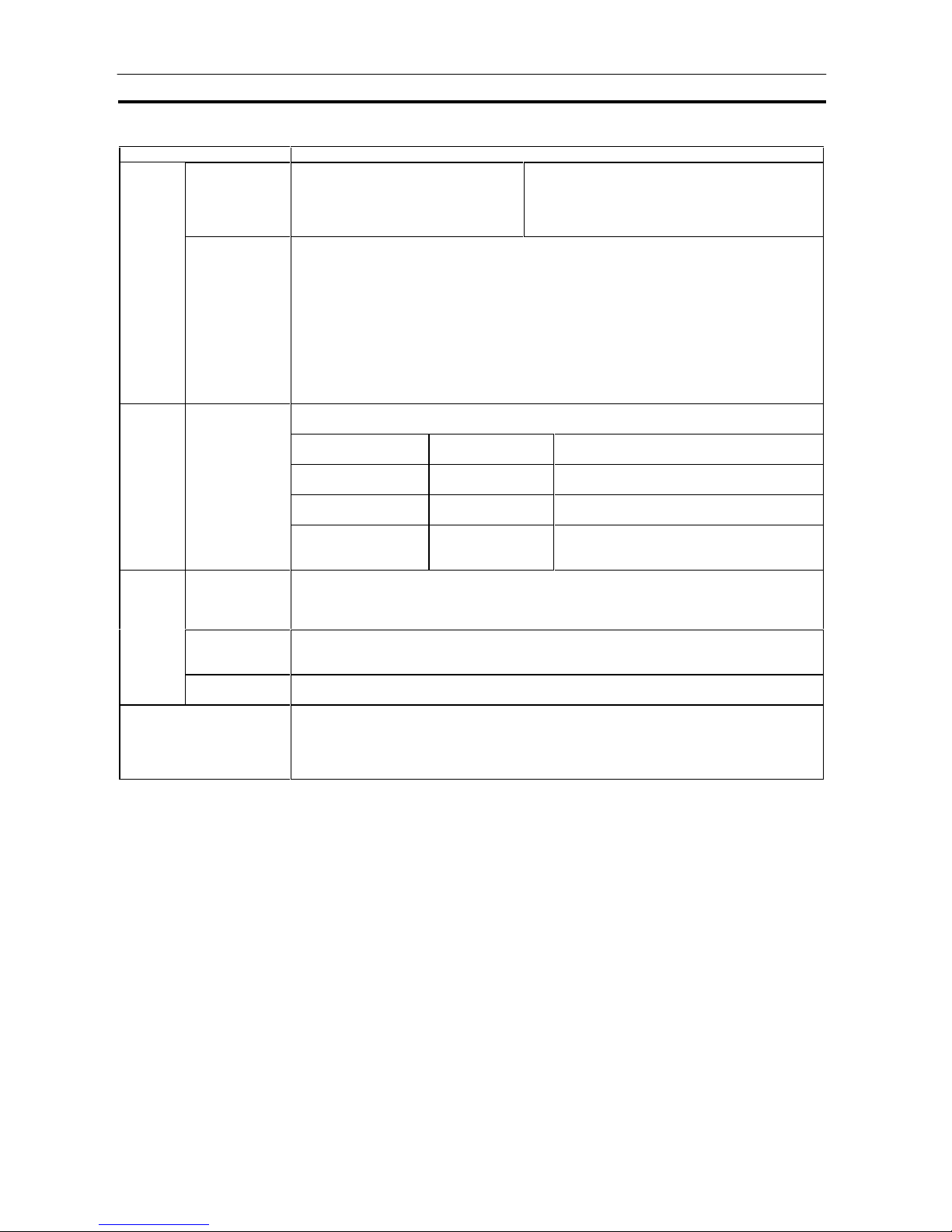
Specifications Section 1-3
40
Item Description
External
I/O
I/O via CPU Unit By data exchange with computer or
networked Loop Control Unit via the
Node Terminal block
Note: The Controller Link Data Link
must be used.
Send to computer: 128 contacts, 16 words
Send to computer: 1 block, 4 blocks
Receive from computer: 32 contacts, 2 words
Send to other node PC: 32 contacts, 2 words
Receive from other node PC: 32 contacts, 2 words
FINS command
to Loop Control
Unit
Read/write of ITEMs in Loop Control Unit function blocks and execution of run/stop
commands are possible from the CPU Unit (including other networked nodes) or host
computer by issuing the following FINS commands to the Loop Control Unit.
- READ MULTIPLE ITEMS IN FUNCTION BLOCK (0240 HEX)
- WRITE MULTIPLE ITEMS IN FUNCTION BLOCK (0241 HEX)
- READ ITEM IN MULTIPLE FUNCTION BLOCKS (0242 HEX)
- WRITE ITEM IN MULTIPLE FUNCTION BLOCKS (0243 HEX)
- READ UNIT INFORMATION (0501 HEX)
- ECHOBACK TEST (0801 HEX)
- READ ERROR LOG (2102 HEX)
- CLEAR ERROR LOG (2103 HEX)
Allocated
area
A Data Memory area comprising continuous 3836 words is used as communications I/O
area common to the Loop Control Units (3 units) on the PC.
Data memory for
communications
I/O
System error
information
8 words x 3 units =
24 words
Unit address, Loop Control Unit run status,
CPU Unit run status, data update check code
Area to send to
computer
16 words x 32
blocks = 512 words
Data send area to the host computer on
which the CX-Process Monitor is running
Area to send to all
nodes
2 words x 50 blocks
= 100 words
Data send area to all nodes (PCs or
computers) on Controller Link
Area to receive from
all nodes
2 words x 50 blocks
x 32 nodes = 3200
words
Data receive area from all nodes (PCs or
computers) on Controller Link
System
common
status
signals
Status output
signal for
sequence control
Constantly ON flags, constantly OFF flags, clock pulse (ON/OFF every 0.5 and 1 seconds)
Clock timing
output signal
Differential output at 00:00 every day, noon every day, every 10 minutes, every minute and
every 10 seconds
Note: The CPU Unit’s clock data are read as these clock data.
Calendar/clock
output signal
Year, year/month, month/hour, day/time, hour/minute and minute/second
Note: The CPU Unit’s clock data is read as these clock data.
Error display By front panel LED: unit number setting error, hardware test error, function block database
error, battery error
Storage of function block execution-related error codes to ITEM 003 of each function
block: source/destination designation error, illegal function block combination, illegal
parameter, etc.
Page 61

Specifications Section 1-3
41
1-3-4 Outline of PID Block Specifications
This item mainly describes an outline of the PID block specifications.
In the Basic PID block (Block Model 011) and Advanced PID block (Block
Model 012), the functions are set to ON and OFF. For actual details on each
ITEM setting, see the descriptions for each block.
: supported, : not
supported
Item Description Basic
PID
Advan-
ced PID
Number of points 1
Input Range -15.00 to +115.00%
PV (Process
Variable) Input
Operation function None (Calculation of square root, first-order lag, bias,
etc. is required by external blocks.)
Sampling cycle According to the specified operation cycle of this block
(one of 0.1, 0.2. 0.5, 1, 2 seconds or 1 to 128 seconds)
PV error input When the PV error contact turns ON, the Loop Control
Unit is forced to enter the Manual mode, and the MV
value active at that moment is held. At the same time,
the PV error is transferred to the CX-Process Monitor.
Number of points 1
Setting range -15.00 to +115.00%
Remote/Local
switching
Possible
SP rate-of-change
limitter
Possible (0 to 115.00%/s)
PV tracking Match the SP (Set Point) to the PV (Process Variable)
if the Loop Control Unit is in the Local and Manual
modes when PV tracking is set to ON.
SP (Set Point)
Bumpless
processing
between
primary/secondary
loops
When the self node is performing cascade control as
the secondary controller, processing is performed on
the MV of the primary controller to be input.
Deviation PV compensation Arithmetic operation (addition, subtraction, substitution)
is performed on the PV signals to be input to the PID
control section when the PV compensation input switch
is ON.
PID Control Control method Advanced PID (Various PID methods (proportional
priority type, PV differential priority type, deviation
differential type, etc.) can be selected according to the
settings of parameters and .)
Control action Direct/reverse switchable
PID constant 1 set
Automatic setting (AT: auto-tuning) by the limit cycle
mode is possible.
Proportional band: 0.1 to 999.9% (0.1% increments)
Integral time: 0 to 9999 s. (1 second increments)
0: No accumulator
Integral stop can be indicated from external contacts.
Differential time: 0 to 9999 s. 0: No differentiation
Manual reset -320.00 to 320.00 (0.01% increments)
Number of points 1 setMV
(Manipulated
Variable)
Output range -320.00 to +320.00%
Output refresh
cycle
According to the specified operation cycle of this block
(one of 0.1, 0.2. 0.5, 1, 2 seconds)
Auto/manual
switching
Possible (according to CX-Process Monitor, CX-
Process Tool or contact signal from Step Ladder
Program block/Contact Distributor block)
High/low MV limit High limit: -320.00 to +320.00%, low limit: -320.00 to
+320.00%
Page 62

Specifications Section 1-3
42
Item Description Basic
PID
Advan-
ced PID
MV high rate-ofchange limit
0 to 115.00%/s
Preset MV
switching
When the preset MV switch is set to ON, the MV
switches to the preset MV (fixed value) and control is
continued at this value.
MV hold The MV (Manipulated Variable) is held at the current
value when the MV hold switch is ON.
MV tracking The MV is switched (tracks) to the input value from other
blocks.
MV
compensation
Arithmetic operation (addition, subtraction, substitution)
is performed on the MV signals from the PID control
section when the MV compensation input switch is ON.
Out-of-range
processing at MV
output destination
block
PID accumulator is stopped when the range is exceeded
on the function block to which MV is connected.
MV
(Manipulated
Variable)
MV error input MV error is transferred to CX-Process Monitor when the
MV error contact turns ON.
Alarm PV alarm 4 (high/high limit, high limit, low limit, low/low limit),
setting range: each -15.00 to +115.00%
Hysteresis: 0 to +115.00%
Deviation alarm 1 (ON outside deviation)
State Output 1 current Set Point output (-15.00 to +115.00%),
1 deviation output (-115.00 to +115.00%)
Page 63

Specifications Section 1-3
43
1-3-5 Software Specifications
The following software (sold separately) is required to use the Loop Control
Unit:
CX-Process Tool: Tool for preparing function block data (essential)
CX-Process Monitor: Tool for monitoring/setting the Loop Control Unit (This
software is not required when using SCADA an d other
third-party software.)
CX-Process Tool Specifications
Item Specification
Product name CX-Process
Model WS02-LCTC1
Applicable PC-series CS1 Series
Applicable Unit Loop Control Unit
Computer PC AT or compatibleApplicable
computer
CPU Min. required: Pentium 133 MHz or faster, Recommended: Pentium MMX166
MHz or faster
OS Microsoft Windows NT4.0 Service Pack 4 or later, Windows 95, 98, Me, or 2000
(See note.)
Note: Microsoft Windows NT4.0 is required for preparing tag data to be used by
the CX-Process Monitor. This data cannot be prepared on Windows 95/98.
Memory Min. required: 32 Mbytes, Recommended: 64 Mbytes or more
Hard disk space Min. required: 20 Mbytes of free space, Recommended: 30 Mbytes or more of
free space
Monitor Min. required: SVGA, Recommended: XGA or higher
CD-ROM drive At least one
Mouse Recommended: Microsoft mouse or compatible pointing device
Using the FinsGateway SerialUnit Driver
Communications protocol with PC: Host Link (not supported on Peripheral bus)
The computer is connected to the CPU Unit peripheral port or built-in RS-232C
port, or RS-232C port of the Serial Communications Unit/Board.
- Connector cable: When connecting to the CPU Unit peripheral ports: Model
CS1W-CN (2 m, 6 m)
When connecting to the CPU Unit’s RS-232C port: Model XW2Z-- (2 m,
5 m)
(For details on model numbers, see 2-3 Connecting to CX-Process Tool and CX-
Process Monitor. )
Connection with CPU
Unit (or Serial
Communications
Board/Unit)
Using the CX-Server
Communications protocol with PC: Host Link or peripheral bus
Using the FinsGateway CLK (PCI) Driver
The Driver is installed on the computer on which the PCI Controller Link Support
Board is mounted to enable communications with the PC on which the Controller
Link Unit is mounted.
Connection via
Controller Link
Using the FinsGateway Controller Link Driver or the CX-Server
The Driver is installed on the computer on which the ISA Controller Link Support
Board is mounted to enable communications with the PC on which the Controller
Link Unit is mounted.
Connecting
method
Connection via Ethernet Using the FinsGateway ETH_UNIT Driver or the CX-Server
The Driver is installed on the computer on which the Ethernet Board is mounted to
enable communications with the PC on which the Ethernet Unit is mounted.
Offline operation functions - Setting of function block ITEM data (including System Common block settings)
- Software wiring of analog signals
- Pasting, displaying, and printing text-string comments (memos) in block or
ladder diagrams.
- Description of Step Ladder Program block commands
- Setting of tags for CX-Process Monitor (on block designated as the source in the
Send to Computer block, contacts and analog signals)
- Initialization of Loop Control Unit memory (RAM)
Page 64

Specifications Section 1-3
44
Item Specification
Online operation functions - Downloading of function block data (download/upload to and from Loop Control
Unit)
- Run/stop command for Loop Control Unit (all function blocks)
- System monitor run status: Monitoring/manipulation of System Common block
(Block Model 000) (including monitoring of load rate of function blocks in each
operation cycle group)
- Loop Control Unit monitor run status: Confirmation of function block wiring
operation (including operation stop/stop cancel on each function block),
confirmation of Step Ladder Program operation
- Autotuning PID constants and other parameters.
Note: Windows 95 does not support access via a PCI Control Link Support Board. A Pentium 150-MHz
processor or better is recommended for Windows Me.
Page 65

Specifications Section 1-3
45
CX-Process Monitor Specifications
Item Descriptions
Product name CX-Process
Model WS02-LCTC1
Applicable PC-series CS1 Series
Applicable Unit Loop Control Unit
Personal computer PC AT or compatible
CPU Min. required: Pentium 133 MHz or faster, Recommended: Pentium MMX233
MHz or faster
OS Microsoft Windows NT4.0 Service Pack 4 or later or Windows 2000 (Windows
95/98 cannot be used.)
Memory Min. required: 64 Mbytes, Recommended: 96 Mbytes or more
Hard disk drive Min. required: 150 Mbytes of free space, Recommended: 200 Mbytes or more
of free space
Monitor Min. required: XGA, Recommended: XGA or higher, min. 1024 x 768 dots,
256 colors
CD-ROM drive At least one
Mouse Recommended: Microsoft mouse or compatible pointing device
Applicable
computer
Sound board 1 pce.
Connecting
method
Connection with CPU Unit
(or Serial Communications
Board/Unit)
When
FinsGateway
SerialUnit
version is
used.
The computer is connected to the CPU Unit peripheral ports or
integrated RS-232C port, or RS-232C port of the Serial
Communications Unit. (Only a 1:1 connection is possible.)
- Connector cable:
When connecting to the CPU Unit peripheral ports: Model
CS1W-CN (2 m, 6 m)
When connecting to the CPU Unit’s RS-232C port: Model
XW2Z-- (2 m, 5 m)
(For details on model numbers, see 2-3 Connecting to CX-
Process Tool and CX-Process Monitor.
- Communications protocol with PC: Host Link (not supported
on Peripheral bus)
Connection via Controller
Link
When
FinsGateway
Controller
Link version
is used.
The FinsGateway Controller Link version is instal led on the
computer on which the Controller Link Support Board is
mounted to enable communications with the PC on which the
Controller Link Unit is mounted.
Loop Control Unit data specification
method
Function blocks, analog signals and contact signals (including parameters)
that are designated as the source by the Send to Computer blocks (Block
Models 401 to 404) are appended a tag number by the CX-Process Tool.
Specify this tag number to specify the Loop Control Unit data.
When reading from the Loop Control Unit:
Use the terminal to computer send area in the Data Memory for the node
terminals on the CPU Unit.
When performing operations on the Loop Control Unit:
Write to the function blocks that are specified as the source designation in the
Send to Computer block without using the terminal to computer send area.
Note: Microsoft Windows NT4.0 is required for preparing tag data to be used
by the CX-Process Monitor. This data cannot be prepared on Windows
95/98.
Mode name Description Connection method
On-demand read
mode:
CX-Process Monitor reads the
data in the terminal to
computer send area whenever
necessary.
One of Host Link,
Ethernet or Controller
Link
Data exchange method with CPU Unit
mounted on Loop Control Unit
Data Link mode: CX-Process Monitor reads the
terminal to computer send area
at all times by the Controller
Link data link.
Only Controller Link is
possible
Page 66

Specifications Section 1-3
46
Item Specification
Offline operation functions Prepare the user configuration screen for use in the online operation screen.
Online
operation
functions
Overview
screen
Place buttons for progressing to the Control screen, Trend screen and other
screens. 4 columns and 8 lines are displayed on each screen (max. 12
screens).
User
Configuration
screen
Control screen Control blocks such as the PID blocks and Indication blocks, and some
Operation blocks are displayed for up to 8 loops in a single screen in the form
of a field device. The maximum number of screens is 400.
This screen displays the Set Point, PV and MV numeric values, displays PV
as a bar graph, and can be used for changing Set Point, MAN and other
setting values. The color of bar graphs changes when an alarm occurs.
You can progress to the Tuning screen from the Control screen.
Tuning screen This screen is for setting P, I, D parameters in Control blocks such as the PID
blocks, and for setting alarm setting values. PV, Set Point and MV can be
tuned while their trends are monitored. The maximum number of screens is
3200.
Run stop/stop cancellation are possible on each function block.
Note: Only the Control block that is designated as the source at the 1-Block
Send Terminal to Computer block can be registered.
Trend screen The analog signals (analog values such as the Control block Set Point, PV
and MV, and other analog values) input from the terminals to the computer
are collected at a fixed cycle and saved to a file. If necessary, up to 8 analog
signals can be displayed on one screen in the form of a multi-dot recorder.
Real time
trend
12 hour’s of data is saved at 10-second
cycles appended with up to 160 tags.
Historic trend 10 day’s of data is saved at 1-minute
cycles appended with up to 320 tags.
Data collected
(logger function)
Batch trend 10-day’s of data is saved at 1-minute
cycles appended with up to 320 tags when
the Trend Start signal is ON.
Data display Horizontal (time) axis: 2, 4, 8, 12 and 24 hour time units
can be scrolled
Vertical (8-point common) axis: Graduation can be
enlarged by a factor or 1, 2, 5 and 10.
Data is displayed from the time when the specified display
start time is reached.
Display color: red, yellow, green, blue, magenta, purple,
cyan, white
Graphic screen This screen displays changes in the plant status using graphic elements
representing plant devices pasted to the screen from the graphic elements
library (provided with the CX-Process Monitor). The maximum number of
screens is 200.
Fixed graphic elements provided in library: Devices, thermometers,
transmitters, orifices, text
Variable graphic elements provided in library:
Analog input: Bar graph display, numeric indication, tanks
Analog output: Numeric setting (by AO Terminal Settings from Computer
block)
Contact input: Pumps, valves, indicators
Contact output: Switches (by DO Terminal Settings from Computer block)
Annunciator
screen
This screen notifies the operator of alarms or errors that occur by changing
the display color and emitting sound. At the same time, a 32-character
message is displayed over two lines on screen elements.
A total of 16 screen elements (4 columns x 4 lines) can be displayed on each
screen. The maximum number of screens is 5.
Operation
Guide/Message
screen
This screen displays pre-registered 128-character messages over two lines
together with the date of occurrence when the specified internal switch is set
to ON.
Max. number of registerable messages: 100, Number of display colors: 7
Up to 1000 messages are displayed in a single screen.
System Monitor
screen
This screen displays the Loop Control Unit operation run/stop commands,
operation start/stop status, execution errors , RAM sum errors, battery errors,
and the status of the Controller Link Data Link.
Page 67

Specifications Section 1-3
47
Item Specification
Online
operation
functions
System
Fixed
screen
Alarm Log
screen
A record of alarms (time of error occurrence, tag name, PV or MV current
value at occurrence, alarm type, etc.) that occur and that are input from the
Control and Alarm blocks is saved and displayed as a list later .
Up to 1000 alarm messages are displayed in a single screen.
Operation Log
screen
A record of changes (date and time of change, tag name, original ITEM data
setting, new ITEM data setting, etc.) made to ITEM data on the Loop Control
Unit in the Control or Tuning screen is saved and displayed as a list later.
Up to 1000 operation messages are displayed in a single screen.
System Monitor
Log screen
This screen displays a log of the run/stop history and a history of execution
errors that occur on the Loop Control Unit together with the date of
occurrence.
Page 68

How to Use Function Blocks for Specific Operations Section 1-4
48
1-4 How to Use Function Blocks for Specific Operations
To perform this specific operation Perform the following See page:
Direct exchange of large amounts
of data between the CPU Unit and
function blocks for data exchange
with a PT (Programmable Terminal)
for example
Use the Expanded CPU Unit Terminal
Blocks (Block Models 455 to 458).
Function Block
Reference Manual
Continuous data exchange with the
CPU Unit
Use the CPU Unit Terminal blocks (Block
Models 451 to 454).
3-3 Exchanging Data
with the CPU Unit
Read/write of specified data
(ITEMs) from a CPU Unit (including
a CPU Unit on a networked PC)
whenever necessary
Execute the CMND (DELIVER
COMMAND) instruction in the Step
Ladder Program, and issue the FINS
command (ITEM read/write command).
Continuous data exchange with a
Loop Control Unit at another node
Use Controller Link and the Node
Terminal blocks (Send Terminal to All
Nodes, Receive Terminal from All Nodes),
and execute the Controller Link Data Link
(at any setting).
3-4 Exchanging Data
with CX-Process
Monitor/SCADA
Software and with Other
Nodes
Appendix-2 How to Use
the Node Terminal Block
Continuous monitoring and
manipulation of all ITEM data in
multiple Control blocks (max. 4
blocks) on CX-Process Monitor
Use the Node Terminal blocks (4-Block
Send Terminal to Computer or 1-Block
Send Terminal to Computer).
3-4 Exchanging Data
with CX-Process
Monitorr/SCADA
Software and with Other
Nodes
Appendix-2 How to Use
the Node Terminal Block
Data
Exchange
Reading/writing specific ITEMs for
Control, Operation, and External
Controller Blocks with SCADA
software
Using Receive All Blocks (Block Model
461) and Send All Blocks (Block Model
462) to transfer Loop Control Unit data
using tags created with CX-Process Tool.
3-4 Exchanging Data
with CX-Process
Monitorr/SCADA
Software and with Other
Nodes
Instruction of run start/stop of the
Loop Control Unit (all function
blocks) from the CPU Unit
whenever necessary
Execute the CMND (DELIVER
COMMAND) instruction in the Step
Ladder Program, and issue the FINS
command (ITEM read/write command) to
change ITEM 014 (run/stop command) of
the System Common block. Or, use the
ITEM setting commands (Block Models
171 and 172) to stop ITEM 014 (run/stop
command) of the System Common block.
(In this case, operation cannot be started.)
Note: Operation can also be stopped or
started on CX-Process Tool and
CX-Process Monitor.
Instruction of operation stop/stop
cancellation on individual function
blocks from the CPU Unit whenever
necessary
Execute the CMND (DELIVER
COMMAND) instruction in the Step
Ladder Program, and issue the FINS
command (ITEM read/write command) to
change ITEM 000 (stop block operation
command) of the relevant block.
Note: Arithmetic operation stop/stop
cancel on a relevant block can also
be indicated by monitoring the run
status on CX-Process Tool.
3-2 Description of
Operation (page 84)
Execution of required processing
on the CPU Unit according to run
status (e.g. in RUN mode,
execution error, function block data
error) of the Loop Control Unit
Execute the required processing on the
CPU Unit taking bits 00 to 05 of the nth
leading words of the CPU Bus Unit as the
input conditions.
Run/
Stop
Execution of required processing
on the Loop Control Unit according
to run status (e.g. operation mode,
fatal error, Output OFF) of the CPU
Unit
Execute the required processing on the
Loop Control Unit using the Step Ladder
Program block based upon the CPU Unit
run status of ITEMs 007 to 011 and 013 in
the System Common block.
3-3 Exchanging Data
with the CPU Unit
High-speed
processing
High-speed processing of specific
function blocks
Set the operation cycle of the relevant
function block to a shorter value.
3-2 Description of
Operatio (page 84)
Page 69

How to Use Function Blocks for Specific Operations Section 1-4
49
To perform this specific operation Perform the following See page:
High-density
monitor
High-density monitoring of analog
signals
Monitor analog signals by the Field Terminal
blocks (Block Models 501 to 587) and Send
to Computer blocks (Block Models 401 to
404)
3-4 Exchanging Data
with CX-Process Monitor
and with Other Nodes
Appendix-2 How to Use
the Node Terminal Block
Monitoring/
Setting
External
Controllers
Monitoring and setting a standalone external controller.
Connect an ES100X Controller to the RS232C port on the Loop Control Unit and use
the ES100X Controller Terminal (Block
Model 045).
Function Block
Reference Manual
Batch Data
Collection
Data collection by a certain timing
within sequence processing in a
batch processing plant
Use the Batch Data Collector block (Block
Model 174)
Function Block
Reference Manual
ON/OFF control Use the 2-position ON/OFF block (Block
Model 001).
Heating/cooling ON/OFF control Use the 3-position ON/OFF block (Block
Model 002).
Function Block
Reference Manual
Time-proportional control Use the Analog/Pulse Width Converter
block (Block Model 192).
5-1 Basic Examples of
PID Control (page 152)
and Function Block
Reference Manual
Application of input filter on PV Use the First-order Lag block (Block Model
141).
Application of bias on PV
Application of ratio on Set Point
and PV
Use the Ratio Setting block (Block Model
033) or the Addition/Subtraction block
(mode 121).
Entry of differential pressure
transmitter to calculate flowrate
Use the Square Root block (Block Model
131) (with low-end cutout function).
Function Block
Reference Manual
Entry of pulse output flowmeter
for accumulation of flowrate
Use the Pulse Input Unit, and enter to the
Accumulator for accumulated value input
block (Block Model 184) for continuous
accumulation.
5-1 Basic Examples of
PID Control (page 152)
and Function Block
Reference Manual
Temperature and pressure
correction
Use the Temperature and Pressure
Correction block (Block Model 136).
Function Block
Reference Manual
Setting of the PID constant
values for multiple words
Use the Constant Item Setting block (Block
Model 171).
5-1 Basic Examples of
PID Control (page 152)
and Function Block
Reference Manual
Switching of multiple Set Point
values
Use the Constant Selector block (Block
Model 165) or the Constant Item Setting
block (Block Model 171).
5-1 Basic Examples of
PID Control (page 152)
and Function Block
Reference Manual
Switching of multiple PID sets Use the Constant Item Setting block (Block
Model 171).
5-1 Basic Examples of
PID Control (page 152)
and Function Block
Reference Manual
Ramp control of Set Point values
(program control)
Use the Ramp Program block (Block Model
155) or the Segment Program block (Block
Model 156).
5-1 Basic Examples of
PID Control (page 152)
and Function Block
Reference Manual
Cascade control Use a serial connection for the Basic PID
block (Block Model 011) or Advanced PID
block (Block Model 012).
5-2 Examples of Applied
Control Types (page
161) and Function Block
Reference Manual
Dead time compensation control Use the Dead Time Compensation block
(Block Model 149) or the Advanced PID
block (Block Model 012).
5-2 Examples of Applied
Control Types (page
161) and Function Block
Reference Manual
Feedforward control
Analog
control
Non-interfering control
Use the Advanced PID block (Block Model
012) or the Lead/Delay block (Block Model
147).
5-2 Examples of Applied
Control Types (page
161) and Function Block
Reference Manual
Page 70

How to Use Function Blocks for Specific Operations Section 1-4
50
To perform this specific operation Perform the following See page:
Sample PI control Use the ON/OFF Timer block (Block
Model 206).
5-2 Examples of Applied
Control Types (page
161) and Function Block
Reference Manual
PID control with differential gap Use the Constant Item Setting block
(Block Model 171).
Selective control Use the Rank Selector block (Block
Model 161).
Analog
control
Using fuzzy control based on
knowledge from ambiguous
expressions
Use the Fuzzy Logic block (Block Model
016).
Performing calculation is engineering
units rather than percentages
Performing special calculations, su ch
as trigonometric or logrithmic
operation
Use the Arithmetic Operation block
(Block Model 126).
Special math
operations
Calculating statistics (e,g., average,
standard deviation, etc) for time
sequence data
Use the Time Sequence Data Statistics
block (Block Model 153).
Function Block
Reference Manual
Accumulation (accumulator) of
instantaneous analog signals such as
flowrate signals on the Loop Control
Unit
Use the Accumulator for instantaneous
value input block (Block Model 150).
5-1 Basic Examples of
PID Control (page 152)
and Function Block
Reference Manual
Continuous accumulation of 4-digit
accumulated value signals (repeat
signals 0000 to 9999) and conversion
to 8-digit signals
Use the Accumulator for accumulated
value input block (Block Model 184).
Input and accumulation of low-speed
pulse signals such as the power
signal
Use the Contact input/Accumulated
value output block (Block Model 185).
Function Block
Reference Manual
Notification of accumulated values on
a field mechanical counter for contact
inputs
Use the Accumulated Value
Input/Contact Output block (Block Model
186).
Batch flowrate capture Use the Batch Flowrate Capture block
(Block Model 014).
Ratio control of accumulated values Use the Batch Flowrate Capture block
(Block Model 014) and the Blended PID
block (Block Model 013).
Addition of accumulated values Use the Accumulated Value Input Adder
block (Block Model 182)
Accumulation
processing
Multiplication of analog signals with
accumulated values
Use the Accumulated Value Analog
Multiplier block (Block Model 183)
Function Block
Reference Manual
AND, OR and other logical operations
on the Loop Control Unit
One-shot contact output of the ON
input state when the contact state
changes from OFF to ON and vice
versa only in 1-operation cycles
(system common operation cycle)
Constantly ON contacts and other
system contacts
Step progression control and other
control on the Loop Control Unit
Acceptance of relays in the Step
Ladder Program
Use the Step Ladder Program block
(Block Model 301).
Use the Internal Switch block (Block
Model 209).
Execution of special processing at
each fixed cycle longer than operation
cycle in Step Ladder Program
Generate a fixed cycle timing signal by
the Clock Pulse block (Block Model
207).
Appendix-1 How to Use
the Step Ladder Program
Block and Function Block
Reference Manual
Execution of timers/counters on the
Loop Control Unit
Use the Timer block (Block Model 205)
and the Counter block (Block Model
208).
Function Block
Reference Manual
Sequence
control
Changing PID constants and other
parameters in stages according to a
process value (e.g., temperature).
Use the Level Check block (Block Model
210) and the Constant ITEM Setting
block (Block Model 171) together to
change paramters for other blocks
according to the level.
Page 71

How to Use Function Blocks for Specific Operations Section 1-4
51
To perform this specific operation Perform the following See page:
Constant transmission of
constants as analog signals
Use the Constant Generator block (Block
Model 166).
Setting of constants to specified
ITEMs under certain conditions
Use the Constant Item Setting block (Block
Model 171).
3-1 Configuration of
Function Blocks and
Function Block
Reference Manual
Constant
setting/selection
Selection of one of multiple
constants and transmission of
that constant as an analog signal
Use the Constant Selector block (Block
Model 165).
Function Block
Reference Manual
Analog signal
setting/
selection
Setting of analog signals to
specified ITEMs under certain
conditions
Use the Variable ITEM Setting block (Block
Model 171).
3-1 Configuration of
Function Blocks and
Function Block
Reference Manual
Selection of one of multiple
analog signals and transmission
of that analog signal as an analog
signal
Use the Input Selector block (Block Model
162).
Function Block
Reference Manual
Selection of the maximum value
from multiple analog signals and
transmission of that maximum
value as an analog signal
Selection of the minimum value
from multiple analog signals and
transmission of that minimum
value as an analog signal
Selection of the nth largest value
from multiple analog signals and
transmission of the signal as an
analog signal
Use the Rank Selector block (Block Model
161).
Function Block
Reference Manual
Switching of sensors on a
different measuring system or
measurement target
Use the 3-input Selector block (Block Model
163).
Switching of operation nodes on
a different measuring system or
measurement target
Use the 3-output Selector block (Block
Model 164).
Changing two settings with a
ramp (e.g., opening and closing
valves)
Use the Ramped Switch block (Model Block
167).
Analog signal
setting/
selection
Converting ranges of analog
signals merely by setting values
for 0% and 100% inputs and 0%
and 100% outputs
Use the Range Conversion block (Block
Model 127).
Comparison of constant and
analog signals
Use the Constant Comparator block (Block
Model 202)
Analog
signal/
constant
comparison
Comparison of two analog signals Use the Variable Comparator block (Block
Model 203)
Manipulation and monitoring of
ON/OFF valve with open/close
limit switches
Use the ON/OFF Valve Manipulator block
(Block Model 221)
Manipulation and monitoring of
motors
Use the Motor Manipulator block (Block
Model 222)
Manipulation and monitoring of
reversible motors
Use the Reversible Motor Manipulator block
(Block Model 223)
Manipulation/
monitor/
control of
special
external
control target
Manipulation of a electric
positional-proportional motor as
the control target
Use the Basic PID (Block Model 011)/
Advanced PID block (Block Model 012) and
Motor Opening Manipulator block (Block
Model 224)
Page 72
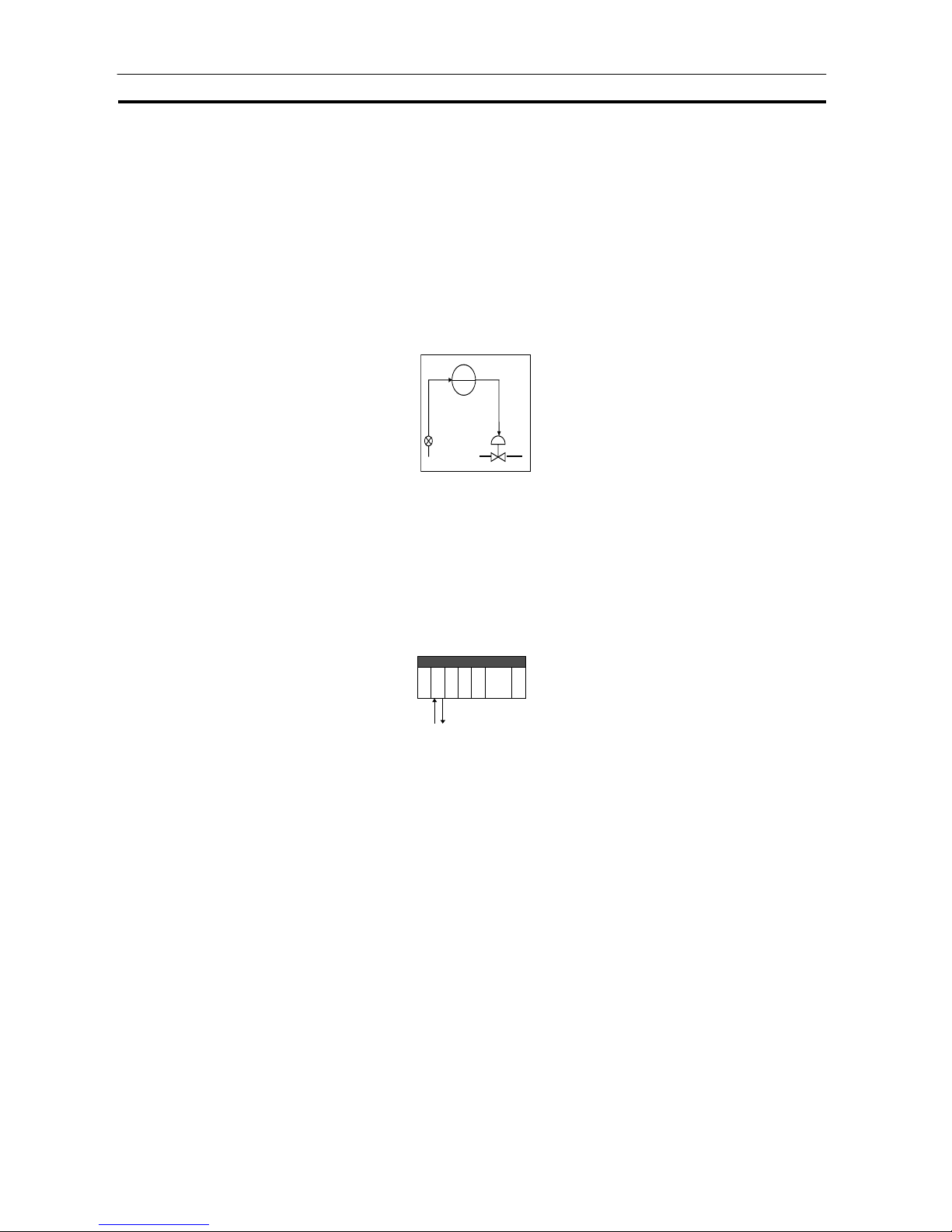
Basic Procedure for Using the Loop Control Unit Section 1-5
52
1-5 Basic Procedure for Using the Loop Control Unit
This section describes the basic procedure for using the Loop Control Unit.
For examples of actual procedures, see Section 4 Simple Examples of Use.
1. Design
1) Prepare an instrumentation drawing.
PIDPV MV
See this Section (for understandin g which func ti ons can be used on the
Loop Control Unit).
See Section 5 Examples of Function Block Combinations.
2) Decide on the PC system configuration.
This mainly involves selection of the Analog Input and Output Units.
See 1-2 Configuration of Instrumentation System.
See Section 3 Mechanism of the Loop Control Unit.
3) Select the required function blocks.
See 1-4 How to Use Function Blocks for Specific Operations.
See Section 3 Mechanism of the Loop Control Unit.
Page 73

Basic Procedure for Using the Loop Control Unit Section 1-5
53
4) Decide on the function block system configuration.
AI 4-point/AO
4-point Termi n al
PV
Basic PID
Block
Model 011
Anal og i npu t
MV
Anal og ou t pu t
See Section 5 Examples of Function Block Combinations.
Refer to the Function Block Referenc e Manu al.
5) Decide on the data to be monitored and manipulated by CX-Process
Monitor.
Refer to the CX-Process Monitor Oper at ion Manua l.
6) Assess the load rate and the external I/O refresh cycle.
See 1-2 Configuration of Instrumentation System.
See 3-2 Description of Operation.
7) Assess fail-safe countermeasures.
See 3-5 Fail-safe Countermeasure Guidelines.
2. Preparing Function Block Data (by CX-Process Tool)
1) Set up and start CX-Process Tool.
Prepare the function block
data on CX- Process Tool
running on the computer.
Refer to CX-Process Tool Operation Manual.
2) Set the System Common block data.
(For example, set the operation cycle and leading Data Memory address
for the Node Terminals.)
Refer to the Function Block Referenc e Manu al.
3) In CX-Process Tool, wire the analog signals between the Selector blocks
(analog signals and accumulated value signals only).
Refer to the CX-Process Tool Operation Manual.
Page 74

Basic Procedure for Using the Loop Control Unit Section 1-5
54
4) Set the ITEMs in each function block.
(If necessary, program step ladder commands in the Step Ladder Program
block including contact signals.)
Refer to CX-Process Tool Operation Manual.
Refer to the Function Block Referenc e Manu al.
Note Set function block initial setting parameters (refer to the item "(S): Initial
setting data" describing how to read/write in the Function Block Referenc e
Manual) on CX-Process Tool.
5) Using CX-Process Monitor
Set the Terminals to Personal Computer for CX-Process Monitor.
Set the monitor tags for CX-Process Monitor and create the monitor tag
files.
Refer to the CX-Process Monitor Oper at ion Manua l.
OR
5) Using SCADA Software
Set the Send All Blocks, Receive All Blocks, or Expanded CPU Unit
Terminal blocks.
Set the CSV tags and create the CSV tag files.
Refer to the CX-Process Monitor Oper at ion Manua l.
3. Setting up the Loop Control Unit
1) Mount the Loop Control Unit and wire the Analog Input and Output Units.
The Loop Control Unit itself need not be wired.
See 2-2 Installation and refer to the manual for other Analog Input and
Output Units.
2) Set the unit number setting switch on the front panel of the Loop Control
Unit.
See 2-1 Names and Functions of Parts.
Refer to the Analog Input and Output Unit Manuals.
3) Connect the Programming Devices.
Refer to Programming Devices (CX-Programmer or Programming
Console) Operation Manual.
4) Turn power ON to the PC.
5) Create I/O tables using the Programming Devices.
Page 75

Basic Procedure for Using the Loop Control Unit Section 1-5
55
Refer to the Programming Devices (CX-Programmer or Programming
Console) Operation Manual.
6) If necessary, set the communications conditions of the serial
communications port in the PC Setup using the Programming Devices.
Refer to the Programming Devices (CX-Programmer or Programming
Console) Operation Manual.
7) Set the allocated Data Memory (D) on the Analog Input and Output Units
using the Programming Devices .
Refer to the Analog Input and Output Unit manuals.
4. Downloading the function block data to the Loop Control Unit
1) Turn power OFF to the PC.
2) Set the unit number setting switch on the front panel of the CPU Unit.
Refer to the CS1 PC Operation Manual.
3) Connect the CPU Unit to the computer on which CX-Process Tool is
running.
4) Turn the PC ON.
5) Set the network address (000), node address (01) and unit address (unit
number + 10 Hex in decimal).
Refer to the CX-Process Tool Operation Manual.
6) Perform the Host Link connection operation on CX-Process Tool ([File]-
[Initialize Serial Port]) .
Refer to the CX-Process Tool Operation Manual.
7) Download the function block data to the Loop Control Unit specified in the
Function Block Data Sheet of CX-Process Tool ([Execute]-[Download]).
Refer to the CX-Process Tool Operation Manual.
Peripheral port or RS-232C port
CPU Unit
Loop Control Unit
Prepare function block data on
CX-Process Tool on the
computer.
Function block
data
Page 76

Basic Procedure for Using the Loop Control Unit Section 1-5
56
Note Check the following points before you start Loop Control Unit operation.
(1) The correct combination of Analog I/O Units must be mounted.
(2) The unit address on the front of the Analog I/O Units must match the unit
number set on the Field Terminal block. Otherwise, input/output
(read/write) operations will be performed by mistake on the data of
another Special I/O Unit (having the unit number set on the Field
Terminal block).
(3) The correct defaults of the System Common block on the Loop Control
Unit must be set. In particular, make sure that same applications as those
for other PCs are not set for the Data Memory (D) for the Node Terminals
on the CPU Unit to be used by the Loop Control Unit.
8) Execute the run/stop command on CX-Process Tool ([Execute]-
[Operation]-[Monitor run status]) or turn the PC power OFF then back ON
again.
Refer to CX-Process Tool Operation Manual.
9) Check the LEDs on the front panel of the Loop Control Unit (RUN LED lit,
ERC LED out).
See 7-1 Errors and Alarm Troubleshoo ting.
5. Trial Operation
1) Execute the run/stop command on CX-Process Tool ([Execute]-
[Operation]-[Monitor run status]) or turn the PC power OFF then back ON
again.
See 3-2 Description of Operations.
Refer to CX-Process Tool Operation Manual.
2) Monitor the run status on CX-Process Tool ([Execute]-[Operation]-[Monitor
run status]).
Execute the load rate check and other diagnostic checks.
Refer to the CX-Process Tool Operation Manual.
Note To disable inadvertent generation of analog signals when running of the Loop
Control Unit is started merely for checking the load rate, disconnect the
analog output connections.
3) Check the wiring on CX-Process Tool ([Validate action]-[Start]).
Refer to the CX-Process Tool Operation Manual.
4) Set up and start CX-Process Monitor.
Refer to CX-Process Monitor Operation Ma nua l.
Page 77
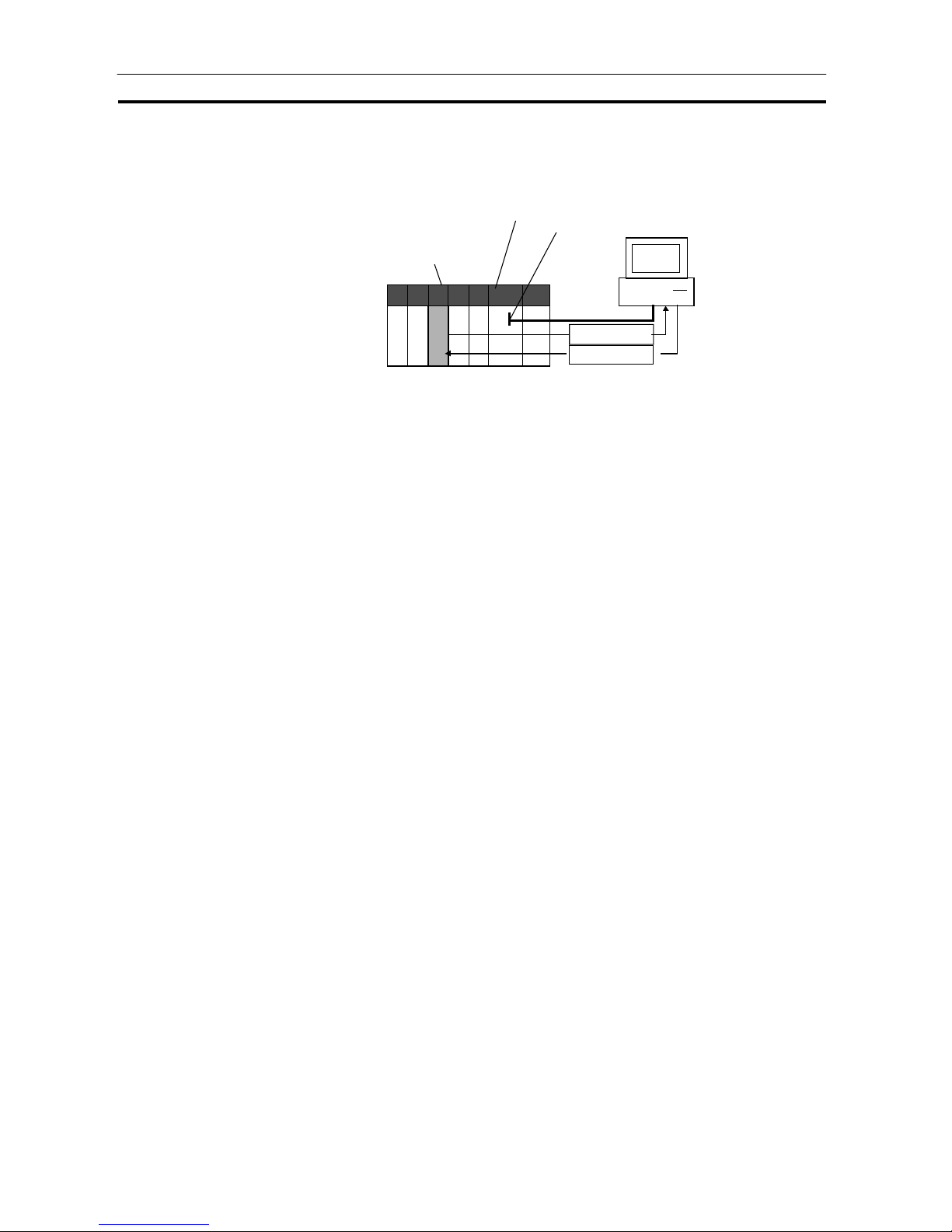
Basic Procedure for Using the Loop Control Unit Section 1-5
57
5) Set the Set Point and other settings on CX-Process Monitor.
Refer to the CX-Process Monitor Oper at ion Manua l.
Peripheral port or RS-232C port
CPU Unit
Loop Control Unit
Set the Set Point and PID
constants, and monitor
PV and other settings on
CX-Process Monito r
running on the computer.
Run status
Run operation
6. Actual Operation
1) Tune the Loop Control Unit using the CX-Process Monitor. (For example,
change the settings and PID constants.)
Refer to the CX-Process Monitor Oper at ion Manua l.
2) Monitor PV and alarms on CX-Process Monitor.
Refer to the CX-Process Monitor Operation Manual.
Page 78

Names and Functions of Parts Section 2-1
59
SECTION 2
Components, Installation and Wiring
2-1 NAMES AND FUNCTIONS OF PARTS ...................................................... 60
2-1-1 Names and Functions of Parts..................................................................................................................... 60
2-2 INSTALLATION............................................................................................. 64
2-2-1 Mountable Units..........................................................................................................................................64
2-2-2 Mounting Procedure.................................................................................................................................... 64
2-2-3 Handling the Analog Input/Output Unit...................................................................................................... 65
2-3 CONNECTING TO CX-PROCESS TOOL AND
CX-PROCESS MONITOR ............................................................................. 66
2-3-1 Connecting by Host Link............................................................................................................................. 66
2-3-2 Connecting by the Controller Link Support Board...................................................................................... 67
Page 79

Names and Functions of Parts Section 2-1
60
2-1 Names and Fu ncti on s of Parts
2-1-1 Names and Functions of Parts
100.5 mm
130 mm
34.5 mm
UNIT
NO.
LED indicators
Unit number
setting switch
(0 to F)
Backplane
connector
RS-232C
connector
0
Battery
compartment
cover (for
replacing
battery)
RUN
LC001
RD
SD
ERC
ERH
CS
PORT
Unit number setting switch:
Sets the unit number (0 to F) of the Loop Control Unit. Set the unit number of
the Loop Control Unit so that it is not the same as that of other CS1 CPU Bus
Units.
Note The unit address (unit number + 10 Hex) is automatically stored to ITEM041
of the System Common block at the start of CPU Unit running based upon
the unit number set on the unit number setting switch. At the same time, the
same unit address value is automatically stored to the leading address of
each LCU number in Data Memory for the Node Terminals.
RS-232C port:
Used to connect to an ES100X Controller. Using the port is enabled by
creating an ES100X Controller Terminal block (Block Model 045).
Page 80

Names and Functions of Parts Section 2-1
61
LED Indicators
RUN
LC001
RD
SD
ERC
ERH
CS
Indication Name Color State Description
Out
System stopped
A probable cause is one of the following:
Initialization of unit in progress
Unit hardware trouble
No power supply from power supply unit
Unit WDT error
Operation of Loop Control Unit stopped
(A probable cause is one of the following:)
- Regular operation stopped
- CPU Unit operation stop error
- CPU Unit in standby mode
- Load rate exceeded at operation cycle of 2 s
(Operation Cycle Automatic Switching
Generation flag ON)
RUN CPU Unit
running
Green
Lit
Loop Control Unit running
Out
No CPU Unit error
ERH CPU Unit
error
Red
Lit
CPU Unit error
Out
No error
Lit
Error
ERC Loop
Control
Unit error
Red
Blinking
Battery error (only when pin 2 of DIP switch is OFF)
SD Not used
RD Not u sed
Battery
When the battery compartment cover is opened, you can access the battery
mounted as shown below.
Battery
21
ON
The battery is used for backing up the following data in the Loop Control Unit:
Function block data
Error log data
If pin 2 of the DIP switch is OFF and the battery voltage drops or a battery is
not mounted, the ERC LED on the front panel blinks. At the same time, bit 05
of the leading n words of the allocated relay area and ITEM095 of the System
Common block (Block Model 000) become 1 (ON), and the error log code
(0330 for battery error and 0331 for function block database error) is stored
on the Loop Control Unit.
Note If pin 2 of the DIP switch is ON, flash memory contents will be automatically
transferred to RAM at startup, bit 5 of word n will be ON, and ITEM 095 of the
Page 81

Names and Functions of Parts Section 2-1
62
System Common block will be ON. (Battery errors (error code 0330) will not
be stored in the error log.)
When replacing the battery, replace with the following battery type. For
details on how to replace the battery, see 7-2 Ma inte nance.
Product name Model
Battery set C200H-BAT09
Note Operation without a battery is also possibly by setting the Loop Control Unit
to automatically transfer the contents of flash memory to RAM at startup.
Refer to 7-2 Maintenance for details.
DIP Switch
When the battery compartment cover is opened, you can access the DIP
switch shown below.
Battery
21
ON
DIP switch
Pin 2 of the DIP switch is used to specify whether or not flash memory
contents will be automatically transferred to RAM at startup. Any changes to
the setting of the DIP switch are effective when PC power is turned ON or the
Loop Control Unit is reset. Changes made during operation will be ignored.
Note Always turn OFF the power supply to the Loop Control Unit before changing
the settings on the DIP switch.
Appearance Pin Setting Meaning Application
ON1
OFF
(default)
Do not turn ON.
ON
(See note 1.)
Contents of flash
memory transferred to
RAM at startup.
Turn ON to operate without a
battery.
Turn ON to recover RAM contents
from flash memory for a battery
error when functiion block data has
been backed up to flash memory
and a battery error has occurred.
2
OFF
(default)
Contents of flash
memory not transferred
to RAM at startup.
Used to operate with RAM backed
up by the battery.
Note 1 The Loop Control Unit will operate as follows when pin 2 of the DIP switch
has been turned ON to automatically transfer flash memory contents to RAM
at startup:
When the power to the PC is turned ON or the Loop Control Unit is restarted,
the function block data will be transferred from flash memory to RAM before
operation is started. Operation, however, must be started using a cold start.
Operation will not start for a hot start.
If operation is then stopped from the CX-Process Tool, either a hot or cold
start can be used as normal.
When pin 2 is ON, the ERC indicator on the front panel will not flash and bit
05 of word n will not turn ON even if the battery voltage drops or a battery is
not mounted.
21
ON
Page 82

Names and Functions of Parts Section 2-1
63
Note 2 Before turning ON pin 2 on the DIP switch, transfer the function block data to
the flash memory using the CX-Process Tool. If the function block data is not
stored in flash memory, RAM data will be overwritten and deleted at startup.
Page 83

Installation Section 2-2
64
2-2 Installation
2-2-1 Mountable Units
The Loop Control Unit is mounted on the CPU Rack for the CS1 series.
Only the three adjacent slots on the CPU Unit can be used as the mounting
location.
Note The Loop Control Unit cannot be mounted on the I/O Expansion Rack for the
C200H and the SYSBUS Remote I/O Slave Rack.
2-2-2 Mounting Procedure
Follow the procedure below to mount the Loop Control Unit on the
Backplane.
1, 2, 3… 1. Lock the top of the Loop Control Unit onto the Backplane by the hook and
rotate the Loop Control Unit downwards as shown in the figure.
Backplane
Hook
2. Correctly slot the connector of the Loop Control Unit into the connector on
the Backplane.
3. Tighten the mounting screw on the bottom side using a Phillips
screwdriver. During this operation, the Phillips screwdriver must be held at
a slight angle, so leave enough space below each Rack for mounting and
removing the Units.
Page 84

Installation Section 2-2
65
Note Be sure to tighten the mounting screw on the bottom side securely to the
tightening torque of 0.4 N•m.
To remove the Loop Control Unit, loosen the screw at the bottom side using
the Phillips screwdriver, and lift up the bottom side to remove.
Precaution When Handling the Loop Control Unit
Be sure to turn OFF the power to the PC before installing or removing the
Loop Control Unit.
2-2-3 Handling the Analog Input/Output Unit
Note The Loop Control Unit is used in combination with an Analog Input/Output
Unit. Note the following points when handling the Analog Input/Output Unit:
Before starting running of the Loop Control Unit, make sure that the Analog
Input/Output Unit is correctly mounted on the same PC Unit. Even if
running of the Loop Control Unit is started without the Analog Input/Output
Unit mounted on the same PC Unit, warning messages to this effect are
not displayed on the screens of CX-Process Tool and CX-Process Monitor.
The unit number set on the front panel of the Analog Input/Output Unit must
be set to the same as the unit number specified in the Field Terminal block.
If unit numbers should differ, reading and writing will be performed
erroneously on another Specia l I/O Unit ha vi ng the uni t num ber specified in
the Field Terminal block.
Page 85

Connecting to CX-Process Tool and CX-Process Monitor Section 2-3
66
2-3 Connecting to CX-Process Tool and CX-Process Monitor
There are two ways of connecting CX-Process Tool and CX-Process Monitor
to the PC (Programmable Controller): connecting by Host Link and
connecting by the Controller Link Support Boar d .
Note CX-Process Tool and CX-Process Monitor cannot be connected directly to
the Loop Control Unit.
In either connection, use FinsGateway as the communications driver.
Communications
network
Fins Gateway to be used Description
Host Link SerialUnit version Connection to PC peripheral or
RS-232C port (only Host Link
connection supported)
Controller Link
network
Controller Link version
Connection via Controller Link
Support Board to a PC to which
a Controller Link Unit is mounted
Ethernet network
Ethernet version
Connection via an Ethernet port
to a PC to which an Ethernet Unit
is mounted
2-3-1 Connecting by Host Link
Use the Fins Gateway Serial Unit version to connect to the peripheral port of
the PC or RS-232C port over the Host Link.
Connect the computer to the RS-232C port of the CPU Unit’s peripheral port
or to the RS-232C port of the Serial Communications Board/Unit. Note that
the computer cannot be connected to the RS-232C port of the Loop Control
Unit.
Connecting to the peripheral port
of the CPU Unit
Connecting to the RS-232C port of the CPU
Unit or Serial Communications Board/Unit
Computer
(9-pin mal e )
CS1 CPU Unit
Connector cable
CS1W-CN226/626
Peripheral port
RS-2 32C p or t
Computer
(9-pin m ale)
CS1 CPU Un it
Recommended cable XW2Z-20 0S-V
Loop Control Unit
Note 1
In either of the above connections, the serial communications mode is
possible only on the Host Link (SYSMAC WAY), and cannot be connected
by the peripheral bus.
If the Fins Gateway Serial Unit version is not installed, connection by the
Host Link (SYSMAC WAY) is not supported. (The Fins Gateway Serial
Unit version is packed together with CX-Process Tool.)
Even if the CX-Programmer is installed on the computer, connection by
the Host Link (SYSMAC WAY) is not supported.
Page 86

Connecting to CX-Process Tool and CX-Process Monitor Section 2-3
67
The following table shows the connector cables used for connecting to the
computer on which CX-Process Tool is running and to the PC (CPU Unit or
Serial Communications Board/Unit).
Connection port
Serial
communications
mode
Computer Length Model
0.1 m CS1W -CN118 (Note 2)
2.0 m CS1W-CN226
Connection to CPU Unit
peripheral port
Host Link mode PC AT or
compatible
6.0 m CS1W-CN626
2.0 m XW2Z-200S-VConnection to CPU Unit
or RS-232C port of Serial
Communications
Board/Unit
Host Link mode PC AT or
compatible
5.0 m XW2Z-500S-V
Note 2 The CS1W-CN118 conversion cable is used when the RS-232C cable is
connected to the peripheral port of the CPU Unit.
Note 3 Before connecting to the CPU Unit, be sure to set the DIP switch on the front
panel of the CPU Unit.
Connection via peripheral port: Set DIP switch SW4 to ON and set the PC
system setting to Host Link.
Connection via RS-232C port: Set DIP switch SW5 to OFF.
2-3-2 Connecting by the Controller Link Support Board
Use the FinsGateway Controller Link version to connect to the PC over the
Controller Link network.
Note If the FinsGateway Controller Link version is not installed, connection by the
Controller Link is not supported. (The FinsGateway SerialUnit version is
packed together with CX-Process Tool.)
Controller Link Units
Model Mountable PC Unit classification Type
Hardware
connection
CS1W-CLK21 Wired Twisted-pair
CS1W-CLK12 Optical ring
(H-PCF cable)
H-PCF optical
fiber cable
CS1W-CLK52
CS1 CPU Bus Unit
Optical ring
(GI cable)
GI optical fiber
cable
Controller Link Support Boards
Model Transmission medium Applicable computer
3G8F7-CLK12 Optical ring (H-PCF cable)
3G8F7-CLK52 Optical ring (GI cable)
3G8F7-CLK21 Wired
PC/AT or compatible computer
with a PCI bus
3G8F5-CLK21 Wired
3G8F5-CLK11 Optical fiber
PC/AT or compatible computer
with a ISA bus
Page 87

Configuration of Function Blocks Section 3-1
69
SECTION 3
Mechanism of the Loop Control Unit
3-1 CONFIGURATION OF FUNCTION BLOCKS.......................................... 70
3-1-1 Configuration of Function Blocks............................................................................................................... 70
3-1-2 Preparing Function Block Data Sheets........................................................................................................ 70
3-1-3 ITEMs Common to All Function Blocks..................................................................................................... 73
3-1-4 ITEMs Unique to Individual Function Blocks............................................................................................. 74
3-1-5 Connecting Function Blocks........................................................................................................................ 80
3-2 DESCRIPTION OF OPERATION................................................................ 84
3-2-1 When Turning the Power ON to the PC...................................................................................................... 84
3-2-2 Details of Hot Start, Cold Start and Stop State............................................................................................ 87
3-2-3 Indicating run/stop of the Loop Control Unit (common to all function blocks).......................................... 89
3-2-4 Stop each function block operation and cancel operation-stop.................................................................... 89
3-2-5 Monitoring the Run Status of Function Blocks...........................................................................................91
3-2-6 Relationship between CPU Unit states and Loop Control Unit States ........................................................ 92
3-2-7 Specifying the Operation Cycle................................................................................................................... 93
3-2-8 Conditions for Determining the Operation Cycle........................................................................................ 96
3-2-9 Order of Operations..................................................................................................................................... 98
3-2-10 About Load Rate........................................................................................................................................ 100
3-2-11 External I/O Refresh Cycle on the Overall System ................................................................................... 106
3-3 EXCHANGING DATA WITH THE CPU UNIT ....................................... 114
3-3-1 Mutual Exchange of Run Status................................................................................................................114
3-3-2 Exchanging Any Data................................................................................................................................ 117
3-4 EXCHANGING DATA WITH CX-PROCESS MONITOR/SCADA
SOTWARE AND WITH OTHER NODES.................................................122
3-4-1 Data Memory (D) for Node Terminals...................................................................................................... 122
3-4-2 Exchanging Data with CX-Process Monitor.............................................................................................. 126
3-4-3 Exchanging Data with SCADA Software.................................................................................................. 130
3-4-4 Exchanging Data with a Loop Control Unit at Other Node....................................................................... 132
3-5 FAIL-SAFE COUNTERMEASURE GUIDELINES ................................. 135
3-5-1 Measures When the Loop Control Unit Has Stopped Running................................................................. 135
3-5-2 Measures for a CPU Unit fatal error....................................................................................... ................... 137
3-5-3 Required Conditions for the Man-Machine Interface ................................................................................ 137
Page 88

Configuration of Function Blocks Section 3-1
70
3-1 Configuration of Function Blocks
All Loop Control Unit functions can be achieved by wiring the function blocks
in the software.
3-1-1 Configuration of Function Blocks
Function blocks comprise data items called ITEMs each starting from 000.
Function block
ITEM Data
000
001
002
003
004
:
:
Items from 000 to 004 are common to all function blocks.
ITEM006 and onwards differ according to the Block Model.
3-1-2 Preparing Function Block Data Sheets
CX-Process Tool is used to set data to each item in each function block, and
prepare function block data sheets. Function blocks are registered to function
block data sheets by being allocated to a block address (address for
execution). These function block data sheets need only be transferred
(downloaded) to the Loop Control Unit to enable use of the Loop Control
Unit. Function block data sheets are prepared as function block files
appended with the .ist extention.
Note 1 When the Loop Control Unit is shipped from the factory, function block data
sheets are not stored on the Unit. Be sure to prepare function block data
sheets using CX-Process Tool and transfer (download) the sheets to the
Loop Control Unit.
Follow the procedure below to prepare and download function block data
sheets.
1, 2, 3… 1. Allocate the function blocks to block addresses.
Select the function blocks to be used, and allocate them to block
addresses in the function block data sheets.
Function blocks become executable data once they have been allocated
to block addresses.
Page 89

Configuration of Function Blocks Section 3-1
71
Allocatable block addresses are determined as follows according to the type
of function block. Block addresses other than these cannot be allocated.
Function block type Allocable block address
Basic PID (Block Model 011) and other Control
blocks
001 to 032
Square Root (Block Model 131) and other Operation
blocks
100 to 349 (Note 2)
Step Ladder Program block (Block Model 301) 400 to 499
Send to Computer block 501 to 532
Send from All Nodes block 550 to 599
Receive from All Nodes block 600 to 699
CPU Unit Terminal 861 to 876
Expanded CPU Unit Terminal 829 to 860
Field Terminal 901 to 980
Note 2 An internal switch is allocated to block address 349 on CX-Process Tool for
temporarily holding data.
Which function block data is written to or which function block data is read
from is determined by the block address for each ITEM.
Note 3 Block Model and Block Address
The "Block Model" is a number for specifying the type of block and is not set
by the user in CX-Process Tool. Be careful not to confuse the Block Model
with the "block address" that is used as the address for execution that IS set
by the user.
2. Wire analog signals (or accumulated value signals) between function
blocks. (See 3-1-5 Connec ting Fu nc tion Bloc k s described later.)
3. Set ITEM data other than the analog signals.
Note 4 Wiring of analog signals (or accumulated value signals) between function
blocks is also possible by setting the data of each ITEM.
Page 90

Configuration of Function Blocks Section 3-1
72
4. Download the function block data sheets to the Loop Control Unit.
Basic PID
(Block Mode 011)
Function block
Example:
Block address
001
Allocation
Basic PID
(Block Mode 011)
Function block
Example:
Block address
002
Allocation
Square Root
(Block Model 131)
Function block
Example:
Block address
100
Allocation
Function block data sheet (file extention .ist)
Download
Loop Control Unit
Page 91

Configuration of Function Blocks Section 3-1
73
3-1-3 ITEMs Common to All Function Blocks
R/W mode
R: Read, W: Write, R/W: R/W-enabled,
-: R/W-disabled
Note: r and r/w: Read and write for confirmation of CX-
Process Tool operation
ITEM type ITEM No. Name Description
According
to CXProcess
Tool
According
to CXProcess
Monitor
According
to ITEM
Setting
block
According
to Step
Ladder
Program
Contact
input
000 Stop block
operation
command
To stop operation of this function block
using a FINS command (including CXProcess Monitor), set this ITEM to 1.
When this ITEM is returned to 0, a hot
start (state active before the unit was
stopped is continued before operation
is started) is performed.
Note: System Common block (Block Model 000)
ITEM000 cannot be used. (Must be set to
0.)
R/W
001 Comment A comment up to 23 characters long
can be described in this ITEM.
Note: The default in CX-Process Tool is the
name of the function block (eight letters).
R/W
Parameter
002 Block
Model
Set the Block Model of the function
block to be registered (allocated) to
blocks having this number. The
settings of ITEM006 onwards is
determined according to the Block
Model set here.
R/W
Special 003 Execution
error
display
An error code is stored here if the data
that is set to each ITEM in this function
block is inappropriate, an error has
occurred in execution of the function
block, or the function block data is in
error.
Note: For details of error codes, see 7-1 Errors
and Alarm Troubleshooting.
r
Parameter
004 Operation
cycle
Specify the operation cycle group of
this function block. Specify whether to
execute the function block at the
operation cycle (standard setting)
specified in the System Common
block (Block Model 000), or to execute
the block at a different specific
operation cycle group (1 to 5).
Note: To change the operation cycle, first set
System Common block (Block Model 000)
ITEM014 to 0 (stop). The operation cycle
cannot be changed while the Loop Control
Unit is running.
R/W
Note ITEM types and settable modes are the same as for individual ITEMs shown
in 3-1-4 ITEMs Unique to Individual Function Blocks. For details of each
ITEM type, see the explanation for the individual function block.
Page 92
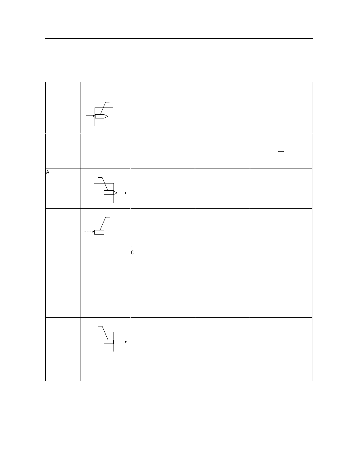
Configuration of Function Blocks Section 3-1
74
3-1-4 ITEMs Unique to Individual Functi on Bl ocks
The following table shows the ITEM types in the case of the Internal Operations block.
ITEM types are divided according to connection and setup mode.
ITEM type
Block diagram
symbol
Description Example Setting method
Analog input
connection
information
× × ×
ITEM number
This is indication data for
receiving analog data (unit:
%) from an analog output
ITEM in another function
block.
PV source designation
(ITEM006) of the Basic
PID block
Specify the block address
of the source designation
and the ITEM number
(analog output ITEM).
Note: This data can also be set as
data for each ITEM or wired
in the software.
Analog input No symbol in block
diagram
This is analog data (unit: %)
that is received from the
source designation specified
by the analog input
connection information
ITEM.
PV input (ITEM007) of
the Basic PID block
Analog output
× × ×
ITEM number
Analog data (unit: %) is sent
to the analog input ITEM of
another function block.
MV output (ITEM087) of
the Basic PID block
This is not specified. (The
connection is made by
specifying output at the
send destination block.)
Contact input
× × ×
ITEM number
Contact signals are input
from the Step Ladder
Program block (Block Model
301) or the Contact
Distributor block (Block
Model 201).
1
Contact signals can also be
output to the Step Ladder
Program block (Block Model
301) or the Contact
Distributor block (Block
Model 201).
Exception:
Note that with some ITEMs the
source designation is sometimes
specified in the same way as
analog input for inputting contact
signals.
Remote/Local switch
(ITEM026) of the Basic
PID block
Contact signals are output
to the contact input ITEM
of the specified block
according to the output
instruction in the Step
Ladder Program block
(Block Model 301) or
according to the
destination of the Contact
Distributor block (Block
Model 201).
Note: Contact signals are input
once via the Step Ladder
Program block or the
Contact Distributor block
also from the System
Common block (Block
Model: 000, state output for
sequence control).
Contact output
× × ×
ITEM number
Contact signals are output
to Step Ladder Program
block (Block Model 301) or
the Contact Distributor block
(Block Model 201).
High alarm output
(ITEM014) of the Basic
PID block
Contact signals are input to
the contact output ITEM of
the specified block
according to the input
instruction in the Step
Ladder Program block
(Block Model 301) or
according to the source
designation of the Contact
Distributor block (Block
Model 201).
Page 93

Configuration of Function Blocks Section 3-1
75
ITEM type
Block diagram
symbol
Description Example Setting method
Accumulated
value input
connection
information
× × ×
ITEM number
This is the indication data
for receiving the
accumulation data
(00000000 to 99999999)
from the accumulated value
output ITEM of another
function block.
Source designation
(ITEM007) of the
Accumulated Value
Input/Contact Output
block (Block Model 186)
Specify the ITEM number
(accumulated value output
ITEM) of the block Block
Model of the source
designation.
Note: This data can also be set as
data for each ITEM or wired
in the software.
Accumulated
value input
No symbol in block
diagram
This is the accumulated
value data that is received
from the source designation
specified by the
accumulated value input
connection information.
Accumulated value
input (ITEM008) of the
Accumulated Value
Input/Contact Output
block (Block Model 186)
Accumulated
value output
× × ×
ITEM number
Accumulation data
(00000000 to 99999999) is
sent to the accumulated
value input ITEM of another
function block.
Accumulated value
(ITEM011, 012) of the
Contact
Input/Accumulated
Value Input block
(Block Model 185)
This is not specified. (The
connection is made by
specifying output at the
send destination block.)
This is internal data upon
which neither the abovedescribed analog
input/output nor contact
input/output operations are
performed.
There are two types of
parameters: parameters
whose value can be
changed by one or a
combination of the methods
1) to 4) below, and
parameters whose value
cannot be changed by any
of the following methods
(only indicated) in 5) below.
1) Parameter value
can be changed by
CX-Process Tool
High alarm setting
(ITEM009) of the Basic
PID block
Set in CX-Process Tool.
2) Parameter value
can be changed by
CX-Process Monitor.
Local Set Point setting
(ITEM023) of the Basic
PID block
Set in CX-Process Monitor.
Parameter Basically, no symbol
in block diagram
(expressed as follows
in some cases as an
explanation)
× × ×
ITEM number
3) Parameter value
can be changed by
the Constant ITEM
Setting block (Block
Model 171) or the
Variable ITEM
Setting block (Block
Model 172).
Proportional band
setting (ITEM054) of
the Basic PID block
Constants or variables
(analog signals) are written
according to the write
destination of the Constant
ITEM Setting block (block
number 171) or the
Variable ITEM Setting
block (block number 172).
Page 94

Configuration of Function Blocks Section 3-1
76
ITEM type
Block diagram
symbol
Description Example Setting method
4) Parameter value
can be changed by
the Step Ladder
Program block
(Block Model 301) or
the Contact
Distributor block
(Block Model 201).
Auto/Manual switch
(ITEM086) of the Basic
PID block
This data is set according
to the Step Ladder
Program block (block
number 301) or the
Contact Distributor block
(block number 201).
Note: Only "parameters" that are
also "contact inputs" (ITEMs
whose ITEM type is
specified as "contact
input/parameters" in the
Function Block Reference
Manual)
5) Indication only (by
CX-Process Monitor
or Step Ladder
Program)
PV execution error
indication (ITEM019) of
the Basic PID block
Cannot be set
The following table shows the ITEM types in the case of the Field Input/Output block.
Function ITEM type Block diagram symbol Description Setting method
Specification
of external
analog input
× × ×
ITEM number
Analog signals are received from
the Analog Input Unit having the
specified unit number.
Specify the unit number of the
Analog Input Unit.
External
analog
input
Analog output Same as regular analog output ITEM
Analog input
connection
information
Analog input
Same as regular analog input ITEM
External
analog
output
Specification
of external
analog output
× × ×
ITEM number
Analog signals are sent to the
Analog Output Unit having the
specified unit number.
Specify the unit number of the
Analog Output Unit.
Specification
of external
contact input
× × ×
ITEM number
Contact signals are received
from the Contact Input Unit
allocated to the leading specified
CIO (channel I/O) Area.
Specify the leading CIO (channel
I/O) Area allocated to the Contact
Input Unit.
External
contact
input
Contact output Same as regular contact output ITEM
Contact input Same as regular contact input ITEMExternal
contact
output
Specification
of external
contact output
× × ×
ITEM number
Specify the leading CIO (channel
I/O) Area allocated to the
Contact Output Unit.
Contact signals are sent to the
Basic I/O Unit allocated to the
leading specified CIO (channel
I/O) Area.
Page 95

Configuration of Function Blocks Section 3-1
77
Note 1 Conventions Used in Describing ITEMs
Refer to the Function Block Refer enc e Manu al.
The Function Block Reference Manual defines reading and writing methods
according to the following four methods as one of R: Read, W: Write, or R/W:
R/W-enabled.
1) According to CX-Process Tool
a) Upload/download of function block files (appended with the .ist
extension)
b) This indicates reading/writing on validate action or monitor run status
windows.
By uploading/downloading by function block files (appended with the
.ist extension), ITEMs are divided into two types: ITEMs to be set as
defaults (called "default data") and ITEMs (called "operation data")
that can be set in either CX-Process Tool or CX-Process Monitor.
R: Upload by file, W: Download by file
(S): Initial setting data, (O): Operation data
r: Read in the validate action window of CX-Process Tool or the
monitor status window of CX-Process Monitor
w: Write in the validate action window of CX-Process Tool
2) According to CX-Process Monitor
This indicates reading/writing on the Tuning screen or Control screen.
3) According to ITEM Setting block
This indicates reading/writing by the Constant ITEM Setting block (Block
Model 171) or the Variable ITEM Setting block (Block Model 172).
4) According to Step Ladder Program
This indicates reading/writing by the Step Ladder Program (Block Model
301) or the Contact Distributor block (Block Model 201).
5) Send/Receive All Blocks
This indicates reading/writing by the Receive All Blocks block (Block
Model 461) or the Send All Blocks block (Block Model 462).
Page 96

Configuration of Function Blocks Section 3-1
78
R/W mode
R: Read, W: Write, R/W: R/W: enabled,
: R/W-disabled
Note: r and r/w: Read and read/write for validate action
or monitor run status by CX-Process Tool or
Monitor. S: Initial setting data, (O): Operation
data
ITEM type ITEM Symbol
Data description
Data range Default
According
to
CXProcess
Tool
According
to CXProcess
Monitor
1
According
to ITEM
Setting
block
According
to Step
Ladder
Program
Send/
Receive
All
Blocks
Data
length
(bytes)
Contact input 000
Stop block operation command
(0: Cancel stop, 1: Stop)
0, 1
1
Parameter 001 Comment 23
characters
0R/W
24
002 Model: Basic PID 011 011 R/W
2
Special 003
Execution error indication
0: Normal, Other: Error
(See Appendix "Execution Error
Code List.")
0000 R
2
ITEM type: Indicates the type of ITEM according to the following categories:
(For details of categories, see 3-1-1 "Configuration of Function Blocks" in this manual.
Contact input, contact output, analog input, analog output, analog input connection information, accumulated
value input, accumulated value output, accumulated value input connection information and parameter
Symbol: Indicates the symbol that is indicated in CX-Process Tool.
Analog input: X, Analog output: Y, Contact input: S, Contact output: U, etc.
ITEM: Indicates the ITEM number in ascending order.
Data description: Indicates the name of the ITEM and its content.
Data range: Indicates the range of data that can be stored.
Default: Indicates the default on CX-Process Tool.
R/W mode: Indicates which of the following modes each ITEM can be read or
written by. (R: Read, W: Write, R/W: R/W-enabled)
CX-Process Tool, CX-Process Monitor (Tuning screen, Control
screen), ITEM Setting blocks (block models 171/172), Step
Ladder Program (block model 301)
Send/Receive All Blocks: Send All Blocks (block model 462) and
Receive All Blocks (block model 461)
Note: On CX-Process Tool, the R/W mode is indicated by W: Download in file
units, R: Upload in file units, r: Read in the validate action window or
monitor run status window, r/w: Read/write in the validate action window or
monitor run status window, (S): Initial setting data (can be set only in CXProcess Tool), (O): Operation data (can be set in both CX-Process Tool
and CX-Process Monitor)
Data length: Indicates the data length (bytes) when
each ITEM is read or written by a FINS
command. This item has no meaning for
other commands.
Each of the ITEMs in function blocks can be read and written by FINS
commands (command codes 0240, 0241, 0242 or 0243 Hex).
All ITEMs excluding the following items can be read and written by FINS
commands:
Sequence commands (ITEM011 onwards) of the Step Ladder Program
block (Block Model 301)
Page 97

Configuration of Function Blocks Section 3-1
79
Note 2 All analog signals on the Loop Control Unit are processed (input or output) in
% units. (They are not processed in engineering units.) Though the data
range varies according to each ITEM, the maximum range is -320.00 to
+320.00%. For example, the data range for PV or Set Point in Control blocks
such as the PID block is -15.00 to +115.00%, and the data range for MV is -
320.00 to +320.00%. When analog signals are connected, data is handled
with "%" as the common unit regardless of differences in the data ranges
between ITEMs. (Note, however, that minus values are regarded as 0.00%
when entered to ITEMs whose data range starts from 0.00%.)
The following three processes are required for displaying or setting in
engineering units:
1) Use CX-Process Tool to specify function blocks such as Control blocks or
analog signals (including parameters) and contact signals (including
parameters) to be monitored by CX-Process Monitor as the source
designation in the Block Send Terminal to Computer blocks.
2) Use CX-Process Tool to set the tag numbers for function blocks or
analog signals (including parameters) and contact signals (including
parameters), and set the high and low limit scaling and unit. (A default
fixed name "tag ITEM" is already allocated to each of the ITEMs in the
function blocks.)
3) Use CX-Process Monitor to select the tag ITEM or tag number that was
selected in CX-Process Tool above, and display or set each ITEM (for
example, Set Point or PV) in the function blocks or the analog signals
(including parameters) and contact signals (including parameters) in
engineering units.
ITEMs in the Step Ladder Program block
The table below shows the content of the 100 ITEMs ITEM011 to ITEM110 in
the case of the Step Ladder Program block (Block Model 301).
ITEM type Block diagram symbol Description Setting method
Sequence
command
CCBBII
Sequence command
CCBBII
CCBBII
Note: CC: Command code,
BB: Block address,
II: ITEM No.
ITEM011 to ITEM110 correspond
to individual commands.
A single command (e.g. LOAD,
OUT) is described to a single ITEM,
and the block address and ITEM
number of the specified input
source and output destination are
described as operands.
Commands are described using
command codes 01 to 30 (e.g.
LOAD is 01 and OUT is 07).
Describe
commands to
ITEM011 to
ITEM110 of the
Step Ladder
Program block
(Block Model
301).
Example of a single command
ITEM Command code (command) Operand
011 01 (LOAD) 001 013 (block address, ITEM No.)
Block address: 001
ITEM number: 013
Command: LOAD (code 01)
Page 98

Configuration of Function Blocks Section 3-1
80
Example of multiple commands
ITEM Command code (command) Operand
011 01 (LOAD) 001013 (block address, ITEM No.)
012 07 (OUT) 100011 (block address, ITEM No.)
013 01 (LOAD) 100011 (block address, ITEM No.)
014 03 (AND) 001026 (block address, ITEM No.)
015 07 (OUT) 002086 (block address, ITEM No.)
016 000 (END) (end of block)
Step Ladder Program
008
Run/stop
command
•
100-011 turns ON at 001-013 ON.
• 002-086 turns ON at 100-011 ON and 001-026 ON.
001-013 100-011
100-011 002-086
001-026
3-1-5 Connecting Function Blocks
For analog signals (variables) and accumulated value signals, specify the
block address and ITEM number of the source designation in the ITEMs of
the send destination block.
Specify contacts not in that function block but in the Step Ladder Program
block (Block Model 301) or the Contact Distributor block (Block Model 201).
Also, specify parameters*1 not in that function block but in the Constant
ITEM Setting block (Block Model 171) or the Variable ITEM Setting block
(Block Model 172).
1: Some parameters cannot be set by ITEM Setting blocks. (For details,
refer to the read/write details of each ITEM in the Function Block
Reference Manual.
Note Contacts can be connected only via the Step Ladder Program block (Block
Model 301) or the Contact Distributor block (Block Model 201). In other
words, contacts cannot be connected directly.
When connecting accumulated values, analog signals and contact signals
between function blocks, only one signal can be connected to a single input
ITEM. However, an infinite number of branches can be made from a single
output ITEM.
× × × ∆ ∆ ∆
Several branches
∆ ∆ ∆
Analog or accumulated
value signal
× × × ∆ ∆ ∆
Several branches
∆ ∆ ∆
Contact signal
Page 99

Configuration of Function Blocks Section 3-1
81
Connecting analog signals (variables) and accumulated value signals
Specify in the analog input ITEMs whic h anal og out put IT EM and its block
address are to be used to introduce analog signal function blocks on the
input side.
Example To introduce ITEM006 (PV) of the Basic PID block of block address 001 from
ITEM011 (Y1) of the Square Root block of block address 100.
011 006
Block address: 100 Block address: 001
Y1
PV
Block ad dress: 001
ITEM number Data
006 100011
Basic PIDSquare Root
Note Connection of analog signals or accumulated value signals can be executed
on CX-Process Tool separately from setting of ITEM data as wiring of
function blocks. (Connection of analog signals or accumulated value signals
can also be set as ITEM data.)
Connecting contact signals
Contact signals are connected via the Step Ladder Program block (Block
Model 301) or the Contact Distributor Block (Block Model 201). *1
Specify both contact inputs (Step Ladder Program block or Contact
Distributor block to specified function block) and contact outputs (specified
function block to Step Ladder Program block or Contact Distributor block) in
the Step Ladder Program block (Block Model 301) or the Contact Distributor
Block (Block Model 201). Do not specify these contact signals to ITEMs in
the specified function block.
Note On CX-Process Tool, connection of contact signals is executed at setting of
ITEM data.
1: As an exception, with some of the ITEMs (PV error input of ITEM018
and MV error input of ITEM090 of the Basic PID block or the Advanced
PID block) contacts are input specified as the source designation.
Page 100

Configuration of Function Blocks Section 3-1
82
Connecting via the Step Ladder Program block
When logical operation is required, use the Step Ladder Program block
(Block Model 301).
Example Input ITEM086 (Auto/Manual switch) of the Basic PID block of block address
001, and output ITEM086 reflected in ITEM026 (Remote/Local switch) of the
Basic PID block of block address 002.
086 011
Block address: 001
A/M
Block address: 400
ITEM number
Command
Command code Operand
011 LOAD 01 001086
012 OUT NOT 12 002026
Step Ladder
Program block
Block address: 400
026
Block address: 002
012
Ba sic PID
block
Basic PID
block
001-086 002-026
A/M
R/L
Remote/Local sw itch
Connecting via the Contact Distributor block
When logical operation is not required, use the Contact Distributor block
(Block Model 201).
Example Input ITEM014 (High PV alarm) of the Basic PID block of block address 001,
and write ITEM014 to ITEM021 (A1 selection command) of the Constant
Selector block (Block Model 165) of block address 100.
014 007
Block address: 001
High PV alarm
Source
designation (S1)
Block address: 101
ITEM number Data
007 001014
008 100021
Contact Distributor
block
Block address: 101
021
Block address: 100
A1 selection command
008
Destination
designation (E1)
Ba sic PID
block
Contact
Selector block
 Loading...