

Omron SYSMAC CS, CS1W-HCA12-V1, CS1W-HCA22-V1, CS1W-HCP22-V1, CS1W-HIO01-V1 Operation Manual
Page 1

Cat. No. W378-E1-02
SYSMAC CS Series
CS1W-HIO01-V1/HCP22-V1/HCA22-V1/HCA12-V1
Customizable Counter Units
OPERATION MANUAL
Page 2

Page 3

CS1W-HIO01-V1/HCP22-V1/HCA22-V1/
HCA12-V1
Customizable Counter Units
Operation Manual
Revised December 2003
Page 4

Terms and Conditions of Sale
1. Offer; Acceptance. These terms and conditions (these "Terms") are deemed
part of all quotes, agreements, purchase orders, acknowledgments, price lists,
catalogs, manuals, brochures and other documents, whether electronic or in
writing, relating to the sale of products or services (collectively, the "Products
by Omron Electronics LLC and its subsidiary companies (“Omron”). Omron
objects to any terms or conditions proposed in Buyer’s purchase order or other
documents which are inconsistent with, or in addition to, these Terms.
2. Prices; Payment Terms.
out notice by Omron. Omron reserves the right to increase or decrease prices
on any unshipped portions of outstanding orders. Payments for Products are
due net 30 days unless otherwise stated in the invoice.
3. Discounts.
sent to Buyer after deducting transportation charges, taxes and duties, and will
be allowed only if (i) the invoice is paid according to Omron’s payment terms
and (ii) Buyer has no past due amounts.
4. Interest.
the maximum legal rate, whichever is less, on any balance not paid within the
stated terms.
5. Orders
6. Governmental Approvals.
costs involved in, obtaining any government approvals required for the importation or sale of the Products.
7. Taxes
real property and income taxes), including any interest or penalties thereon,
imposed directly or indirectly on Omron or required to be collected directly or
indirectly by Omron for the manufacture, production, sale, delivery, importation, consumption or use of the Products sold hereunder (including customs
duties and sales, excise, use, turnover and license taxes) shall be charged to
and remitted by Buyer to Omron.
8. Financial.
to Omron, Omron reserves the right to stop shipments or require satisfactory
security or payment in advance. If Buyer fails to make payment or otherwise
comply with these Terms or any related agreement, Omron may (without liability and in addition to other remedies) cancel any unshipped portion of Products sold hereunder and stop any Products in transit until Buyer pays all
amounts, including amounts payable hereunder, whether or not then due,
which are owing to it by Buyer. Buyer shall in any event remain liable for all
unpaid accounts.
9. Cancellation; Etc.
unless Buyer indemnifies Omron against all related costs or expenses.
10. Force Majeure
resulting from causes beyond its control, including earthquakes, fires, floods,
strikes or other labor disputes, shortage of labor or materials, accidents to
machinery, acts of sabotage, riots, delay in or lack of transportation or the
requirements of any government authority.
11. Shipping; Delivery.
a. Shipments shall be by a carrier selected by Omron; Omron will not drop ship
b. Such carrier shall act as the agent of Buyer and delivery to such carrier shall
c. All sales and shipments of Products shall be FOB shipping point (unless oth-
d. Delivery and shipping dates are estimates only; and
e. Omron will package Products as it deems proper for protection against nor-
12. Claims.
Products occurring before delivery to the carrier must be presented in writing
to Omron within 30 days of receipt of shipment and include the original transportation bill signed by the carrier noting that the carrier received the Products
from Omron in the condition claimed.
13. Warranties
Products will be free from defects in materials and workmanship for a period of
twelve months from the date of sale by Omron (or such other period expressed
in writing by Omron). Omron disclaims all other warranties, express or implied.
(b) Limitations
EXPRESS OR IMPLIED, ABOUT NON-INFRINGEMENT, MERCHANTABIL-
Cash discounts, if any, will apply only on the net amount of invoices
Omron, at its option, may charge Buyer 1-1/2% interest per month or
. Omron will accept no order less than $200 net billing.
. All taxes, duties and other governmental charges (other than general
If the financial position of Buyer at any time becomes unsatisfactory
except in “break down” situations.
constitute delivery to Buyer;
erwise stated in writing by Omron), at which point title and risk of loss shall
pass from Omron to Buyer; provided that Omron shall retain a security interest in the Products until the full purchase price is paid;
mal handling and extra charges apply to special conditions.
Any claim by Buyer against Omron for shortage or damage to the
. (a) Exclusive Warranty. Omron’s exclusive warranty is that the
All prices stated are current, subject to change with-
Buyer shall be responsible for, and shall bear all
Orders are not subject to rescheduling or cancellation
. Omron shall not be liable for any delay or failure in delivery
Unless otherwise expressly agreed in writing by Omron:
. OMRON MAKES NO WARRANTY OR REPRESENTATION,
ITY OR FITNESS FOR A PARTICULAR PURPOSE OF THE PRODUCTS.
BUYER ACKNOWLEDGES THAT IT ALONE HAS DETERMINED THAT THE
PRODUCTS WILL SUITABLY MEET THE REQUIREMENTS OF THEIR
")
INTENDED USE. Omron further disclaims all warranties and responsibility of
any type for claims or expenses based on infringement by the Products or otherwise of any intellectual property right. (c) Buyer Remedy
gation hereunder shall be, at Omron’s election, to (i) replace (in the form
originally shipped with Buyer responsible for labor charges for removal or
replacement thereof) the non-complying Product, (ii) repair the non-complying
Product, or (iii) repay or credit Buyer an amount equal to the purchase price of
the non-complying Product; provided that in no event shall Omron be responsible for warranty, repair, indemnity or any other claims or expenses regarding
the Products unless Omron’s analysis confirms that the Products were properly handled, stored, installed and maintained and not subject to contamination, abuse, misuse or inappropriate modification. Return of any Products by
Buyer must be approved in writing by Omron before shipment. Omron Companies shall not be liable for the suitability or unsuitability or the results from the
use of Products in combination with any electrical or electronic components,
circuits, system assemblies or any other materials or substances or environments. Any advice, recommendations or information given orally or in writing,
are not to be construed as an amendment or addition to the above warranty.
See http://
lished information.
14. Limitation on Liability; Etc
FOR SPECIAL, INDIRECT, INCIDENTAL, OR CONSEQUENTIAL DAMAGES,
LOSS OF PROFITS OR PRODUCTION OR COMMERCIAL LOSS IN ANY
WAY CONNECTED WITH THE PRODUCTS, WHETHER SUCH CLAIM IS
BASED IN CONTRACT, WARRANTY, NEGLIGENCE OR STRICT LIABILITY.
Further, in no event shall liability of Omron Companies exceed the individual
price of the Product on which liability is asserted.
15. Indemnities
their employees from and against all liabilities, losses, claims, costs and
expenses (including attorney's fees and expenses) related to any claim, investigation, litigation or proceeding (whether or not Omron is a party) which arises
or is alleged to arise from Buyer's acts or omissions under these Terms or in
any way with respect to the Products. Without limiting the foregoing, Buyer (at
its own expense) shall indemnify and hold harmless Omron and defend or settle any action brought against such Companies to the extent based on a claim
that any Product made to Buyer specifications infringed intellectual property
rights of another party.
16. Property; Confidentiality.
sive property of Omron Companies and Buyer shall not attempt to duplicate it
in any way without the written permission of Omron. Notwithstanding any
charges to Buyer for engineering or tooling, all engineering and tooling shall
remain the exclusive property of Omron. All information and materials supplied
by Omron to Buyer relating to the Products are confidential and proprietary,
and Buyer shall limit distribution thereof to its trusted employees and strictly
prevent disclosure to any third party.
17. Export Controls.
licenses regarding (i) export of products or information; (iii) sale of products to
“forbidden” or other proscribed persons; and (ii) disclosure to non-citizens of
regulated technology or information.
18. Miscellaneous
and no course of dealing between Buyer and Omron shall operate as a waiver
of rights by Omron. (b) Assignment
without Omron's written consent. (c) Law.
law of the jurisdiction of the home office of the Omron company from which
Buyer is purchasing the Products (without regard to conflict of law principles). (d) Amendment
Buyer and Omron relating to the Products, and no provision may be changed
or waived unless in writing signed by the parties. (e) Severability
sion hereof is rendered ineffective or invalid, such provision shall not invalidate
any other provision. (f) Setoff
against the amount owing in respect of this invoice. (g) Definitions
herein, “including
nies” (or similar words) mean Omron Corporation and any direct or indirect
subsidiary or affiliate thereof.
www.omron247.com or contact your Omron representative for pub-
. OMRON COMPANIES SHALL NOT BE LIABLE
. Buyer shall indemnify and hold harmless Omron Companies and
Any intellectual property in the Products is the exclu-
Buyer shall comply with all applicable laws, regulations and
. (a) Waiver. No failure or delay by Omron in exercising any right
. Buyer may not assign its rights hereunder
These Terms are governed by the
. These Terms constitute the entire agreement between
. Buyer shall have no right to set off any amounts
” means “including without limitation”; and “Omron Compa-
. Omron’s sole obli-
. If any provi-
. As used
Certain Precautions on Specifications and Use
1. Suitability of Use. Omron Companies shall not be responsible for conformity
with any standards, codes or regulations which apply to the combination of the
Product in the Buyer’s application or use of the Product. At Buyer’s request,
Omron will provide applicable third party certification documents identifying
ratings and limitations of use which apply to the Product. This information by
itself is not sufficient for a complete determination of the suitability of the Product in combination with the end product, machine, system, or other application
or use. Buyer shall be solely responsible for determining appropriateness of
the particular Product with respect to Buyer’s application, product or system.
Buyer shall take application responsibility in all cases but the following is a
non-exhaustive list of applications for which particular attention must be given:
(i) Outdoor use, uses involving potential chemical contamination or electrical
interference, or conditions or uses not described in this document.
(ii) Use in consumer products or any use in significant quantities.
(iii) Energy control systems, combustion systems, railroad systems, aviation
systems, medical equipment, amusement machines, vehicles, safety equipment, and installations subject to separate industry or government regulations.
(iv) Systems, machines and equipment that could present a risk to life or property. Please know and observe all prohibitions of use applicable to this Product.
NEVER USE THE PRODUCT FOR AN APPLICATION INVOLVING SERIOUS
RISK TO LIFE OR PROPERTY OR IN LARGE QUANTITIES WITHOUT
ENSURING THAT THE SYSTEM AS A WHOLE HAS BEEN DESIGNED TO
ADDRESS THE RISKS, AND THAT THE OMRON’S PRODUCT IS PROPERLY RATED AND INSTALLED FOR THE INTENDED USE WITHIN THE
OVERALL EQUIPMENT OR SYSTEM.
2. Programmable Products.
user’s programming of a programmable Product, or any consequence thereof.
3. Performance Data
and other materials is provided as a guide for the user in determining suitability and does not constitute a warranty. It may represent the result of Omron’s
test conditions, and the user must correlate it to actual application requirements. Actual performance is subject to the Omron’s Warranty and Limitations
of Liability.
4. Change in Specifications
changed at any time based on improvements and other reasons. It is our practice to change part numbers when published ratings or features are changed,
or when significant construction changes are made. However, some specifications of the Product may be changed without any notice. When in doubt, special part numbers may be assigned to fix or establish key specifications for
your application. Please consult with your Omron’s representative at any time
to confirm actual specifications of purchased Product.
5. Errors and Omissions.
checked and is believed to be accurate; however, no responsibility is assumed
for clerical, typographical or proofreading errors or omissions.
Omron Companies shall not be responsible for the
. Data presented in Omron Company websites, catalogs
. Product specifications and accessories may be
Information presented by Omron Companies has been
Page 5

Notice:
r
f
OMRON products are manufactured for use according to proper procedures by a qualified operator
and only for the purposes described in this manual.
The following conventions are used to indicate and classify precautions in this manual. Always heed
the information provided with them. Failure to heed precautions can result in injury to people or damage to property.
!DANGER Indicates an imminently hazardous situation which, if not avoided, will result in death or
serious injury.
!WARNING Indicates a potentially hazardous situation which, if not avoided, could result in death or
serious injury.
!Caution Indicates a potentially hazardous situation which, if not avoided, may result in minor or
moderate injury, or property damage.
OMRON Product References
All OMRON products are capitalized in this manual. The word “Unit” is also capitalized when it refers to
an OMRON product, regardless of whether or not it appears in the proper name of the product.
The abbreviation “Ch,” which appears in some displays and on some OMRON products, often means
“word” and is abbreviated “Wd” in documentation in this sense.
The abbreviation “PLC” means Programmable Controller. “PC” is used, however, in some Program-
ming Device displays to mean Programmable Controller.
Visual Aids
The following headings appear in the left column of the manual to help you locate different types of
information.
Reference Indicates supplementary information on related topics that may be of inter-
Ó OMRON, 2001
All rights reserved. No part of this publication may be reproduced, stored in a retrieval system, or transmitted, in any form, o
by any means, mechanical, electronic, photocopying, recording, or otherwise, without the prior written permission o
OMRON.
No patent liability is assumed with respect to the use of the information contained herein. Moreover, because OMRON is constantly striving to improve its high-quality products, the information contained in this manual is subject to change without
notice. Every precaution has been taken in the preparation of this manual. Nevertheless, OMRON assumes no responsibility
for errors or omissions. Neither is any liability assumed for damages resulting from the use of the information contained in
this publication.
Note Indicates information of particular interest for efficient and convenient op-
eration of the product.
est to the user.
1,2,3... 1. Indicates lists of one sort or another, such as procedures, checklists, etc.
v
Page 6

vi
Page 7

TABLE OF CONTENTS
PRECAUTIONS . . . . . . . . . . . . . . . . . . . . . . . . . . . . . . . . . . . xi
1 Intended Audience . . . . . . . . . . . . . . . . . . . . . . . . . . . . . . . . . . . . . . . . . . . . . . . . . . . . . . . . xii
2 General Precautions . . . . . . . . . . . . . . . . . . . . . . . . . . . . . . . . . . . . . . . . . . . . . . . . . . . . . . . xii
3 Safety Precautions. . . . . . . . . . . . . . . . . . . . . . . . . . . . . . . . . . . . . . . . . . . . . . . . . . . . . . . . . xii
4 Operating Environment Precautions. . . . . . . . . . . . . . . . . . . . . . . . . . . . . . . . . . . . . . . . . . . xiii
5 Application Precautions . . . . . . . . . . . . . . . . . . . . . . . . . . . . . . . . . . . . . . . . . . . . . . . . . . . .xiv
6 Data Backup . . . . . . . . . . . . . . . . . . . . . . . . . . . . . . . . . . . . . . . . . . . . . . . . . . . . . . . . . . . . . xvi
7 Conformance to EC Directives . . . . . . . . . . . . . . . . . . . . . . . . . . . . . . . . . . . . . . . . . . . . . . . xviii
SECTION 1
Features and System Configuration . . . . . . . . . . . . . . . . . . . 1
1-1 Outline. . . . . . . . . . . . . . . . . . . . . . . . . . . . . . . . . . . . . . . . . . . . . . . . . . . . . . . . . . . . . . . . . . 2
1-2 Models and System Configurations . . . . . . . . . . . . . . . . . . . . . . . . . . . . . . . . . . . . . . . . . . . 14
SECTION 2
Specifications. . . . . . . . . . . . . . . . . . . . . . . . . . . . . . . . . . . . . . 19
2-1 Performance Specifications. . . . . . . . . . . . . . . . . . . . . . . . . . . . . . . . . . . . . . . . . . . . . . . . . .20
2-2 Contact I/O Specifications (All Units) . . . . . . . . . . . . . . . . . . . . . . . . . . . . . . . . . . . . . . . . . 33
SECTION 3
Nomenclature, Installation, and Wiring. . . . . . . . . . . . . . . . 35
3-1 Names and Functions of Parts. . . . . . . . . . . . . . . . . . . . . . . . . . . . . . . . . . . . . . . . . . . . . . . . 36
3-2 Installation. . . . . . . . . . . . . . . . . . . . . . . . . . . . . . . . . . . . . . . . . . . . . . . . . . . . . . . . . . . . . . . 39
3-3 Wiring . . . . . . . . . . . . . . . . . . . . . . . . . . . . . . . . . . . . . . . . . . . . . . . . . . . . . . . . . . . . . . . . . . 42
3-4 Programming Devices. . . . . . . . . . . . . . . . . . . . . . . . . . . . . . . . . . . . . . . . . . . . . . . . . . . . . .53
3-5 Fail-safe Circuits . . . . . . . . . . . . . . . . . . . . . . . . . . . . . . . . . . . . . . . . . . . . . . . . . . . . . . . . . . 56
SECTION 4
Exchanging Data with the CPU Unit . . . . . . . . . . . . . . . . . . 59
4-1 Overview. . . . . . . . . . . . . . . . . . . . . . . . . . . . . . . . . . . . . . . . . . . . . . . . . . . . . . . . . . . . . . . . 60
4-2 Words Allocated in CIO Area . . . . . . . . . . . . . . . . . . . . . . . . . . . . . . . . . . . . . . . . . . . . . . . . 63
4-3 Words Allocated in DM Area . . . . . . . . . . . . . . . . . . . . . . . . . . . . . . . . . . . . . . . . . . . . . . . . 67
4-4 LR Area. . . . . . . . . . . . . . . . . . . . . . . . . . . . . . . . . . . . . . . . . . . . . . . . . . . . . . . . . . . . . . . . . 71
4-5 Difference between I/O Refreshing in Customizable Counter Units and
That in Other Special I/O Units . . . . . . . . . . . . . . . . . . . . . . . . . . . . . . . . . . . . . . . . . . . . . . 72
SECTION 5
Unit Setup Area . . . . . . . . . . . . . . . . . . . . . . . . . . . . . . . . . . . 77
5-1 Unit Setup Area. . . . . . . . . . . . . . . . . . . . . . . . . . . . . . . . . . . . . . . . . . . . . . . . . . . . . . . . . . . 78
vii
Page 8

TABLE OF CONTENTS
SECTION 6
I/O Memory. . . . . . . . . . . . . . . . . . . . . . . . . . . . . . . . . . . . . . . 85
6-1 Overview. . . . . . . . . . . . . . . . . . . . . . . . . . . . . . . . . . . . . . . . . . . . . . . . . . . . . . . . . . . . . . . . 86
6-2 Details . . . . . . . . . . . . . . . . . . . . . . . . . . . . . . . . . . . . . . . . . . . . . . . . . . . . . . . . . . . . . . . . . . 89
6-3 SR Area . . . . . . . . . . . . . . . . . . . . . . . . . . . . . . . . . . . . . . . . . . . . . . . . . . . . . . . . . . . . . . . . . 93
6-4 AR Area . . . . . . . . . . . . . . . . . . . . . . . . . . . . . . . . . . . . . . . . . . . . . . . . . . . . . . . . . . . . . . . . 98
SECTION 7
Special Functions . . . . . . . . . . . . . . . . . . . . . . . . . . . . . . . . . . 119
7-1 Outline. . . . . . . . . . . . . . . . . . . . . . . . . . . . . . . . . . . . . . . . . . . . . . . . . . . . . . . . . . . . . . . . . . 121
7-2 Interrupt Functions . . . . . . . . . . . . . . . . . . . . . . . . . . . . . . . . . . . . . . . . . . . . . . . . . . . . . . . . 122
7-3 Interrupt Inputs . . . . . . . . . . . . . . . . . . . . . . . . . . . . . . . . . . . . . . . . . . . . . . . . . . . . . . . . . . . 124
7-4 Executing Interrupt Tasks in the CPU Unit. . . . . . . . . . . . . . . . . . . . . . . . . . . . . . . . . . . . . . 125
7-5 Pulse Inputs . . . . . . . . . . . . . . . . . . . . . . . . . . . . . . . . . . . . . . . . . . . . . . . . . . . . . . . . . . . . . . 126
7-6 Pulse Outputs . . . . . . . . . . . . . . . . . . . . . . . . . . . . . . . . . . . . . . . . . . . . . . . . . . . . . . . . . . . . 130
7-7 Analog Outputs . . . . . . . . . . . . . . . . . . . . . . . . . . . . . . . . . . . . . . . . . . . . . . . . . . . . . . . . . . . 138
7-8 Functions Compatible with Servo Drivers with Absolute Encoders . . . . . . . . . . . . . . . . . . 142
7-9 Analog Input Functions. . . . . . . . . . . . . . . . . . . . . . . . . . . . . . . . . . . . . . . . . . . . . . . . . . . . . 154
7-10 Virtual Pulse Output Function (-V1 unit with lot No. 0209__or later only). . . . . . . . . . . . . 161
7-11 Constant Cycle Time Over Clear Function. . . . . . . . . . . . . . . . . . . . . . . . . . . . . . . . . . . . . . 165
7-12 Ladder Library Function . . . . . . . . . . . . . . . . . . . . . . . . . . . . . . . . . . . . . . . . . . . . . . . . . . . . 166
7-13 Back Up Function . . . . . . . . . . . . . . . . . . . . . . . . . . . . . . . . . . . . . . . . . . . . . . . . . . . . . . . . . 175
7-14 Improved Instructions . . . . . . . . . . . . . . . . . . . . . . . . . . . . . . . . . . . . . . . . . . . . . . . . . . . . . . 178
SECTION 8
Unit Operation and Processing Time . . . . . . . . . . . . . . . . . . 185
8-1 Customizable Counter Unit Operation . . . . . . . . . . . . . . . . . . . . . . . . . . . . . . . . . . . . . . . . . 186
8-2 Power Interruptions. . . . . . . . . . . . . . . . . . . . . . . . . . . . . . . . . . . . . . . . . . . . . . . . . . . . . . . . 187
8-3 Cycle Time . . . . . . . . . . . . . . . . . . . . . . . . . . . . . . . . . . . . . . . . . . . . . . . . . . . . . . . . . . . . . . 189
SECTION 9
Troubleshooting . . . . . . . . . . . . . . . . . . . . . . . . . . . . . . . . . . . 203
9-1 Types of Troubleshooting Information . . . . . . . . . . . . . . . . . . . . . . . . . . . . . . . . . . . . . . . . . 204
9-2 Error Log. . . . . . . . . . . . . . . . . . . . . . . . . . . . . . . . . . . . . . . . . . . . . . . . . . . . . . . . . . . . . . . . 204
9-3 Troubleshooting Tables. . . . . . . . . . . . . . . . . . . . . . . . . . . . . . . . . . . . . . . . . . . . . . . . . . . . . 206
9-4 User-defined Errors. . . . . . . . . . . . . . . . . . . . . . . . . . . . . . . . . . . . . . . . . . . . . . . . . . . . . . . . 212
9-5 Troubleshooting Flowcharts . . . . . . . . . . . . . . . . . . . . . . . . . . . . . . . . . . . . . . . . . . . . . . . . . 213
Appendix
A Precautions when Using the CX-Programmer . . . . . . . . . . . . . . . . . . . . . . . . . . . . . . . . . . . 221
Index . . . . . . . . . . . . . . . . . . . . . . . . . . . . . . . . . . . . . . . . . . . . 225
Revision History . . . . . . . . . . . . . . . . . . . . . . . . . . . . . . . . . . . 231
viii
Page 9

About this Manual:
This manual describes the installation and operation of the CS1W-HIO01-V1, CS1W-HCP22-V1,
CS1W-HCA22-V1 and CS1W-HCA12-V1 Customizable Counter Units and includes the sections
described below. The Customizable Counter Units provide both normal contact I/O with special I/O
as ideal control capabilities for many applications. The Customizable Counter Units are classified
as CS-series Special I/O Units.
Please read this manual and all other manuals for the Customizable Counter Units listed below
carefully and be sure you understand the information provided before attempting to install or operate a Customizable Counter Unit.
Manual Cat. No. Contents
CS1W-HIO01-V1/HCP22-V1/
HCA22-V1/HCA12-V1
Customizable Counter Units
Operation Manual
(this manual)
CS1W-HIO01-V1/HCP22-V1/
HCA22-V1/HCA12-V1
Customizable Counter Units
Programming Manual
SYSMAC WS02-CX-@@-EV3
CX-Programmer
User Manual
CQM1H Series
Programmable Controllers
Operation Manual
W378 Describes the hardware and software operation of the Cus-
tomizable Counter Units.
W384 Describes the memory areas and programming instructions
of the Customizable Counter Units.
W414 Provide information on how to use the CX-Programmer, a
Windows-based Programming Device that supports the
CQM1H-series PLCs.
W363 Describes Programming Console operations that can be
used connected to the Customizable Counter Units.
Section 1 describes the features of the Customizable Counter Units and the devices required in
an extended system configuration.
Section 2 provides performance specifications and I/O specifications for the Customizable
Counter Unit.
Section 3 provides the names of the different components of the Customizable Counter Unit and
explains the procedures required for installing and wiring the Unit.
Section 4 provides details on the way in which data is exchanged between the Customizable
Counter Unit and the CPU Unit.
Section 5 provides details on the settings made using the Unit Setup Area in the Customizable
Counter Unit.
Section 6 provides details of the settings made using the I/O memory areas in the Customizable
Counter Unit.
Section 7 provides information on interrupts, pulse inputs, pulse outputs, and analog outputs.
Section 8 explains the internal processing of the Customizable Counter Unit, and the time
required for processing and execution.
Section 9 provides information on troubleshooting errors that can occur with the Customizable
Counter Unit.
The Appendix provides precautions required when programming or monitoring the Customizable
Counter Unit with the CX-Programmer.
ix
Page 10

!WARNING Failure to read and understand the information provided in this manual may result in per-
sonal injury or death, damage to the product, or product failure. Please read each section
in its entirety and be sure you understand the information provided in the section and
related sections before attempting any of the procedures or operations given.
x
Page 11

PRECAUTIONS
This section provides general precautions for using the CS1W-HIO01-V1, CS1W-HCP22-V1, CS1W-HCA22-V1 and
CS1W-HCA12-V1 Customizable Counter Units.
The information contained in this section is important for the safe and reliable application of the Customizable
Counter Units. You must read this section and understand the information contained before attempting to set
up or operate a Customizable Counter Unit.
1 Intended Audience . . . . . . . . . . . . . . . . . . . . . . . . . . . . . . . . . . . . . . . . . . . . . xii
2 General Precautions . . . . . . . . . . . . . . . . . . . . . . . . . . . . . . . . . . . . . . . . . . . . xii
3 Safety Precautions . . . . . . . . . . . . . . . . . . . . . . . . . . . . . . . . . . . . . . . . . . . . . xii
4 Operating Environment Precautions. . . . . . . . . . . . . . . . . . . . . . . . . . . . . . . . xiii
5 Application Precautions . . . . . . . . . . . . . . . . . . . . . . . . . . . . . . . . . . . . . . . . . xiv
6 Data Backup . . . . . . . . . . . . . . . . . . . . . . . . . . . . . . . . . . . . . . . . . . . . . . . . . . xvi
6-1 Automatic Backup . . . . . . . . . . . . . . . . . . . . . . . . . . . . . . . . . . . . . . xvi
6-2 User Programming . . . . . . . . . . . . . . . . . . . . . . . . . . . . . . . . . . . . . . xvii
6-3 Backing Up DM Area to Flash Memory . . . . . . . . . . . . . . . . . . . . . xviii
7 Conformance to EC Directives. . . . . . . . . . . . . . . . . . . . . . . . . . . . . . . . . . . . xviii
7-1 Applicable Directives. . . . . . . . . . . . . . . . . . . . . . . . . . . . . . . . . . . . xviii
7-2 Concepts. . . . . . . . . . . . . . . . . . . . . . . . . . . . . . . . . . . . . . . . . . . . . . xviii
7-3 Conformance to EC Directives . . . . . . . . . . . . . . . . . . . . . . . . . . . . xix
xi
Page 12

Intended Audience 1
1 Intended Audience
This manual is intended for the following personnel, who must also have
knowledge of electrical systems (an electrical engineer or the equivalent).
• Personnel in charge of installing FA systems.
• Personnel in charge of designing FA systems.
• Personnel in charge of managing FA systems and facilities.
2 General Precautions
The user must operate the product according to the performance specifications described in the operation manuals.
Before using the product under conditions which are not described in the
manual or applying the product to nuclear control systems, railroad systems,
aviation systems, vehicles, combustion systems, medical equipment, amusement machines, safety equipment, and other systems, machines, and equipment that may have a serious influence on lives and property if used
improperly, consult your OMRON representative.
Make sure that the ratings and performance characteristics of the product are
sufficient for the systems, machines, and equipment, and be sure to provide
the systems, machines, and equipment with double safety mechanisms.
This manual provides information for programming and operating the Unit. Be
sure to read this manual before attempting to use the Unit and keep this manual close at hand for reference during operation.
!WARNING It is extremely important that a PLC and all PLC Units be used for the speci-
fied purpose and under the specified conditions, especially in applications that
can directly or indirectly affect human life. You must consult with your OMRON
representative before applying a PLC System to the above-mentioned applications.
3 Safety Precautions
!WARNING Do not attempt to take any Unit apart while the power is being supplied. Doing
so may result in electric shock.
!WARNING Do not touch any of the terminals or terminal blocks while the power is being
supplied. Doing so may result in electric shock.
!WARNING Do not attempt to disassemble, repair, or modify any Units. Any attempt to do
so may result in malfunction, fire, or electric shock.
!WARNING Do not touch the Power Supply Unit while power is being supplied or immedi-
ately after power has been turned OFF. Doing so may result in electric shock.
!WARNING Provide safety measures in external circuits, i.e., not in the Programmable
Controller (CPU Unit including associated Units; referred to as “PLC”), in
order to ensure safety in the system if an abnormality occurs due to malfunction of the PLC or another external factor affecting the PLC operation. Not
doing so may result in serious accidents.
xii
Page 13

Operating Environment Precautions 4
• Emergency stop circuits, interlock circuits, limit circuits, and similar safety
measures must be provided in external control circuits.
• The PLC will turn OFF all outputs when its self-diagnosis function detects
any error or when a severe failure alarm (FALS) instruction is executed.
As a countermeasure for such errors, external safety measures must be
provided to ensure safety in the system.
• The PLC outputs may remain ON or OFF due to deposition or burning of
the output relays or destruction of the output transistors. As a countermeasure for such problems, external safety measures must be provided
to ensure safety in the system.
• When the 24-VDC output (service power supply to the PLC) is overloaded
or short-circuited, the voltage may drop and result in the outputs being
turned OFF. As a countermeasure for such problems, external safety
measures must be provided to ensure safety in the system.
!Caution Execute online edit only after confirming that no adverse effects will be
caused by extending the cycle time. Otherwise, the input signals may not be
readable.
!Caution Confirm safety at the destination node before transferring a program to
another node or changing contents of the I/O memory area. Doing either of
these without confirming safety may result in injury.
!Caution Tighten the screws on the terminal block of the AC power supply to the torque
specified in the operation manual. The loose screws may result in burning or
malfunction.
4 Operating Environment Precautions
!Caution Do not operate the control system in the following locations:
• Locations subject to direct sunlight.
• Locations subject to temperatures or humidity outside the range specified
in the specifications.
• Locations subject to condensation as the result of severe changes in temperature.
• Locations subject to corrosive or flammable gases.
• Locations subject to dust (especially iron dust) or salts.
• Locations subject to exposure to water, oil, or chemicals.
• Locations subject to shock or vibration.
!Caution Take appropriate and sufficient countermeasures when installing systems in
the following locations:
• Locations subject to static electricity or other forms of noise.
• Locations subject to strong electromagnetic fields.
• Locations subject to possible exposure to radioactivity.
• Locations close to power supplies.
xiii
Page 14

Application Precautions 5
!Caution The operating environment of the PLC System can have a large effect on the
longevity and reliability of the system. Improper operating environments can
lead to malfunction, failure, and other unforeseeable problems with the PLC
System. Be sure that the operating environment is within the specified conditions at installation and remains within the specified conditions during the life
of the system.
5 Application Precautions
!WARNING Always heed these precautions. Failure to abide by the following precautions
could lead to serious or possibly fatal injury.
• Always connect to a ground of 100
connecting to a ground of 100
• A ground of 100
terminals on the Power Supply Unit.
• Always turn OFF the power supply to the PLC before attempting any of
the following. Not turning OFF the power supply may result in malfunction
or electric shock.
• Mounting or dismounting Power Supply Units, I/O Units, CPU Units, Inner Boards, or any other Units.
• Assembling the Units.
• Setting DIP switches or rotary switches.
• Connecting cables or wiring the system.
• Connecting or disconnecting the connectors.
!Caution Failure to abide by the following precautions could lead to faulty operation of
the PLC or the system, or could damage the PLC or PLC Units. Always heed
these precautions.
• Always turn ON power to the PLC before turning ON power to the control
system. If the PLC power supply is turned ON after the control power supply, temporary errors may result in control system signals because the
output terminals on DC Output Units and other Units will momentarily turn
ON when power is turned ON to the PLC.
• Fail-safe measures must be taken by the customer to ensure safety in the
event that outputs from Output Units remain ON as a result of internal circuit failures, which can occur in relays, transistors, and other elements.
• Fail-safe measures must be taken by the customer to ensure safety in the
event of incorrect, missing, or abnormal signals caused by broken signal
lines, momentary power interruptions, or other causes.
• Interlock circuits, limit circuits, and similar safety measures in external circuits (i.e., not in the Programmable Controller) must be provided by the
customer.
• Always use the power supply voltages specified in the operation manuals.
An incorrect voltage may result in malfunction or burning.
• Take appropriate measures to ensure that the specified power with the
rated voltage and frequency is supplied in places where the power supply
is unstable. An incorrect power supply may result in malfunction.
W or less must be installed when shorting the GR and LG
W or less when installing the Units. Not
W or less may result in electric shock.
xiv
Page 15

Application Precautions 5
• Install external breakers and take other safety measures against short-circuiting in external wiring. Insufficient safety measures against short-circuiting may result in burning.
• Do not apply voltages to the Input Units in excess of the rated input voltage. Excess voltages may result in burning.
• Do not apply voltages or connect loads to the Output Units in excess of
the maximum switching capacity. Excess voltage or loads may result in
burning.
• Disconnect the functional ground terminal when performing withstand
voltage tests. Not disconnecting the functional ground terminal may result
in burning.
• Install the Units properly as specified in the operation manuals. Improper
installation of the Units may result in malfunction.
• Be sure that all the mounting screws, terminal screws, and cable connector screws are tightened to the torque specified in the relevant manuals.
Incorrect tightening torque may result in malfunction.
• Leave the label attached to the Unit when wiring. Removing the label may
result in malfunction if foreign matter enters the Unit.
• Remove the label after the completion of wiring to ensure proper heat dissipation. Leaving the label attached may result in malfunction.
• Use crimp terminals for wiring. Do not connect bare stranded wires
directly to terminals. Connection of bare stranded wires may result in
burning.
• Wire all connections correctly.
• Double-check all wiring and switch settings before turning ON the power
supply. Incorrect wiring may result in burning.
• Mount Units only after checking terminal blocks and connectors completely.
• Be sure that the terminal blocks, Memory Units, expansion cables, and
other items with locking devices are properly locked into place. Improper
locking may result in malfunction.
• Check switch settings, the contents of the DM Area, and other preparations before starting operation. Starting operation without the proper settings or data may result in an unexpected operation.
• Check the user program for proper execution before actually running it on
the Unit. Not checking the program may result in an unexpected operation.
• Confirm that no adverse effect will occur in the system before attempting
any of the following. Not doing so may result in an unexpected operation.
• Changing the operating mode of the PLC.
• Force-setting/force-resetting any bit in memory.
• Changing the present value of any word or any set value in memory.
• Resume operation only after transferring to the new CPU Unit the contents of the DM Area, HR Area, and other data required for resuming
operation. Not doing so may result in an unexpected operation.
• Do not pull on the cables or bend the cables beyond their natural limit.
Doing either of these may break the cables.
• Do not place objects on top of the cables or other wiring lines. Doing so
may break the cables.
xv
Page 16

Data Backup 6
• When replacing parts, be sure to confirm that the rating of a new part is
correct. Not doing so may result in malfunction or burning.
• Before touching a Unit, be sure to first touch a grounded metallic object in
order to discharge any static build-up. Not doing so may result in malfunction or damage.
• When transporting or storing circuit boards, cover them in antistatic material to protect them from static electricity and maintain the proper storage
temperature.
• Do not touch circuit boards or the components mounted to them with your
bare hands. There are sharp leads and other parts on the boards that
may cause injury if handled improperly.
• Data in the DM Area, error log, EM Area, or Timer/Counter Area may
become corrupted if power is not supplied for an extended period of time.
Program the PLC to check SR 24914 before starting operation. If SR
24914 is ON, the memory areas that are normally held during power interruptions will not have been held properly (i.e., the data will be corrupted).
(The data in the DM Area can be backed up to flash memory by turning
ON SR 25200.)
6Data Backup
6-1 Automatic Backup
Data in the Customizable Counter Units is backed up either by a super capacitor or flash memory, as listed in the following table.
DM Area (DM 0000 to DM 6143), EM Area (EM 0000 to EM
2047), error log (DM 6144 to DM 6199), and counter present
values.
A setting is provided to either enable or disable holding EM
Area data. The default is to not hold the data.
User program, read-only DM Area words (DM 6200 to DM
6599), Unit Setup Area (DM 6600 to DM 6655), expansion
instructions information, read/write DM Area words (DM 0000
to DM 6143, see note.)
Note The contents of DM 0000 to DM 6143 are written to flash memory only when
SR 25200 (DM Area Backup Bit) is turned ON.
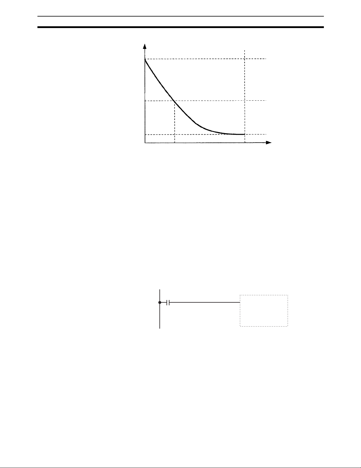
The data in RAM is backed up by the super capacitor for 10 days at 25
backup time varies with the ambient temperature as shown in the following
graph.
Data Data backup
RAM with super
capacitor
Flash memory
°C. The
xvi
Page 17
Data Backup 6
Backup time
10th day
5th day
1st day
Ambient temperature
25°C40°C75°C
Note The times give above assume that the capacitor is completely charged. Power
must be supply to the Unit for at least 15 minutes to completely charge the
capacitor.
The data backed up by the capacitor will become unstable or corrupted if the
backup time is exceeded.
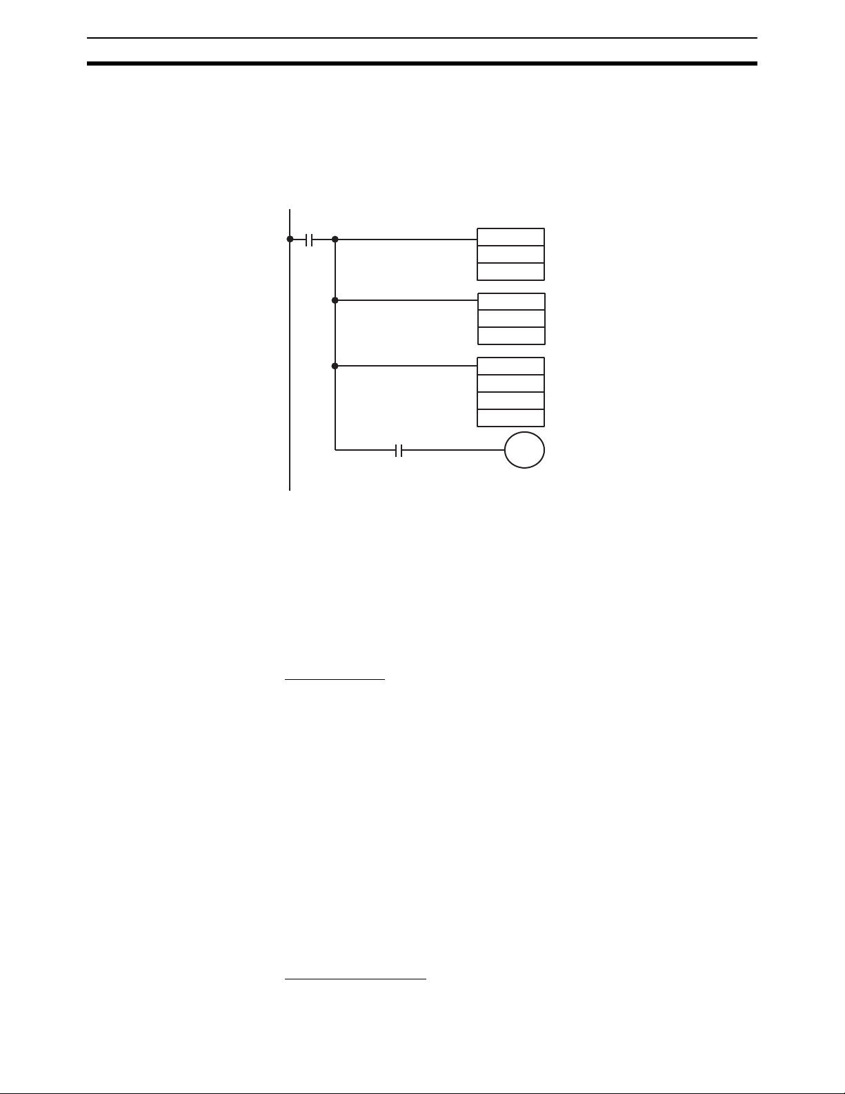
6-2 User Programming
If the power supply is turned OFF for longer than the data backup time (10
days at 25
counter present values, will be lost and any data that is read will be unstable.
If the power supply is to be turned OFF for an extended period of time, the
contents of DM 0000 to DM 6143 can be backed up in flash memory. The
Backup Data Corrupted Flag (SR 24914) can also be used as shown below to
detect when backup data (i.e., data in the DM Area, EM Area, and Error Log,
as well as counter present values) has become corrupted to perform appropriate error processing.
DM 0000 to DM 6143 (read/write portion of DM Area) can be backed up in
flash memory by the user as described in the next section.
°C), the data in the DM Area, EM Area, and Error Log, as well as
24914
Processing for
corruption of data
backed up for
power interruptions
xvii
Page 18
Conformance to EC Directives 7
6-3 Backing Up DM Area to Flash Memory
The contents of DM 0000 to DM 6143 can be written to flash memory by turning ON SR 25200 (DM Flash Memory Backup Bit) in PROGRAM mode.
(SR 25200 will turn OFF automatically when transfer has been completed.)
The data stored in flash memory can be read back to DM 0000 to DM 6143 by
using the XFER(70) instruction as shown below.
Execution
condition
25503
MOV(21)
#0100
LR00
MOV(21)
#0000
LR01
@XFER(70)
#9999
LR00
DM0000
ER Flag
7 Conformance to EC Directives
7-1 Applicable Directives
•EMC Directives
• Low Voltage Directive
7-2 Concepts
EMC Directives
OMRON devices that comply with EC Directives also conform to the related
EMC standards so that they can be more easily built into other devices or
machines. The actual products have been checked for conformity to EMC
standards (see the following note). Whether the products conform to the standards in the system used by the customer, however, must be checked by the
customer.
EMC-related performance of the OMRON devices that comply with EC Directives will vary depending on the configuration, wiring, and other conditions of
the equipment or control panel in which the OMRON devices are installed.
The customer must, therefore, perform final checks to confirm that devices
and the overall machine conform to EMC standards.
xviii
Note Applicable EMC (Electromagnetic Compatibility) standards are as follows:
EMS (Electromagnetic Susceptibility): EN61000-6-2
EMI (Electromagnetic Interference): EN50081-2
(Radiated emission: 10-m regulations)
Low Voltage Directive
Always ensure that devices operating at voltages of 50 to 1,000 VAC or 75 to
1,500 VDC meet the required safety standards for the PLC (EN61131-2).
Page 19

Conformance to EC Directives 7
7-3 Conformance to EC Directives
The CS1W-HIO01-V1, CS1W-HCP22-V1, CS1W-HCA22-V1 and CS1WHCA12-V1 Customizable Counter Units comply with EC Directives. To ensure
that the machine or device in which the Customizable Counter Unit is used
complies with EC directives, the Unit must be installed as follows:
1,2,3... 1. The Customizable Counter Unit must be installed within a control panel.
2. Reinforced insulation or double insulation must be used for the Customizable Counter Unit DC power supplies used for the communications and
I/O power supplies.
3. The Customizable Counter Units complying with EC Directives also conform to the Common Emission Standard (EN50081-2). When a Customizable Counter Unit is built into a machine, however, changes can occur,
particularly for the radiated emission (10-m regulations), due to the structure of the machine, other connected devices, wiring, etc. The customer
must, therefore, perform final checks to confirm that devices and the overall machine using a Customizable Counter Unit conform to EC standards.
xix
Page 20

Conformance to EC Directives 7
xx
Page 21

SECTION 1
Features and System Configuration
This section describes the features of the Customizable Counter Units and the devices required in an extended system
configuration.
1-1 Outline . . . . . . . . . . . . . . . . . . . . . . . . . . . . . . . . . . . . . . . . . . . . . . . . . . . . . . 2
1-1-1 Outline . . . . . . . . . . . . . . . . . . . . . . . . . . . . . . . . . . . . . . . . . . . . . . . 2
1-1-2 Features . . . . . . . . . . . . . . . . . . . . . . . . . . . . . . . . . . . . . . . . . . . . . . 5
1-1-3 Application Examples . . . . . . . . . . . . . . . . . . . . . . . . . . . . . . . . . . . 7
1-2 Models and System Configurations . . . . . . . . . . . . . . . . . . . . . . . . . . . . . . . . 14
1-2-1 Models . . . . . . . . . . . . . . . . . . . . . . . . . . . . . . . . . . . . . . . . . . . . . . . 14
1-2-2 System Configurations . . . . . . . . . . . . . . . . . . . . . . . . . . . . . . . . . . . 14
1
Page 22
Outline Section 1-1
1-1 Outline
1-1-1 Outline
The Customizable Counter Units are CS-series Special I/O Units that can be
programmed using a ladder program and provide both standard contact I/O
and special I/O (including pulse inputs, pulse outputs, and analog outputs).
(I/O support depends on the model of the Unit.)
The I/O of a Customizable Counter Unit can be controlled by the ladder program in it without intervention from the program in the CPU Unit to achieve
high-speed I/O processing. By customizing a Customizable Counter Unit
using its I/O, programming, and interrupt functions, a wide range of applications requiring high-speed response can be implemented in a distributed processing system where the Customizable Counter Unit functions as a
coprocessor for the CPU Unit.
Customizable Counter Unit capabilities also facilitate machine modularization
and standardization, and make machine and device maintenance much easier.
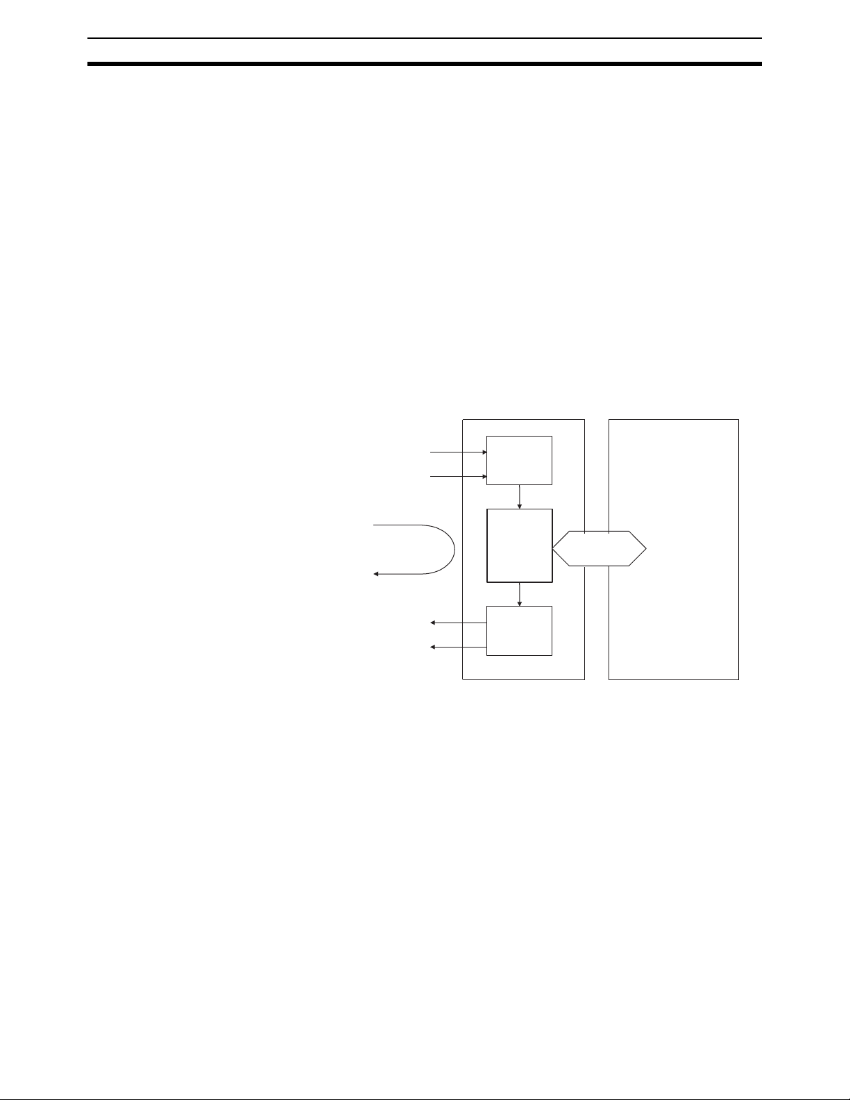
Normal inputs
Pulse inputs
High-speed control loop
Normal outputs
Pulse or analog outputs
Customizable Counter Unit
Input data
Ladder
program
Output data
Data exchange
with the CPU Unit
CS-series CPU Unit
• High-speed I/O processing is enabled by the small-capacity ladder program in the Customizable Counter Unit that achieves a high-speed cycle.
The Customizable Counter Unit also supports various types of interrupt
programming, enabling it to handle special high-speed applications previously handled by sensor controllers and microcomputer boards. The Customizable Counter Unit can also perform part of the functions previously
performed by High-speed Counter Units, Position Control Units, and Analog Output Units.
• Other features include normal interrupts, interval timer interrupts, and
high-speed counter interrupts, in addition to a high-precision timer that
uses a pulse counter (CS1W-HCP22-V1 only), target value interrupts for
a pulse output value (CS1W-HCP22-V1 only), analog output instructions
for analog slope control (CS1W-HCA22-V1 only), and range comparisons
for the present value of a high-precision pulse output counter timer.
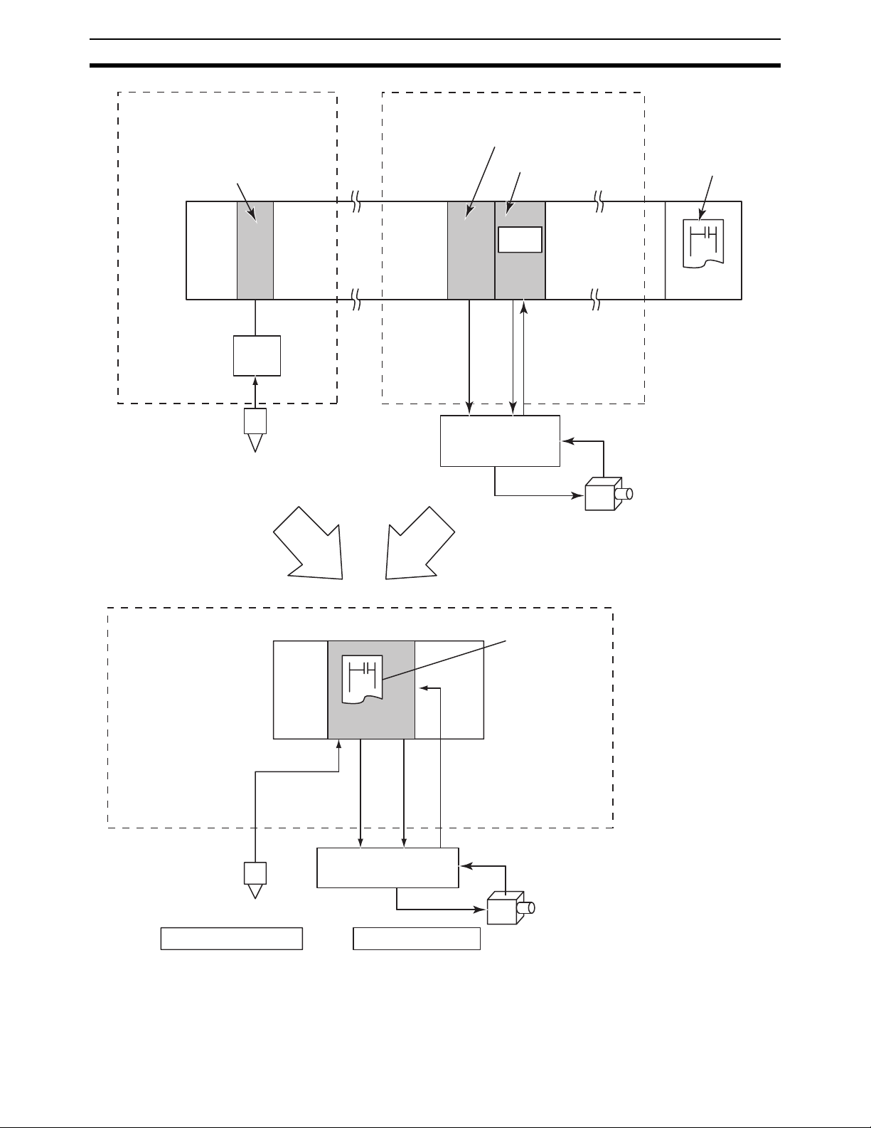
• The CS1W-HCA12-V1 is a special I/O unit of CS-series, having all of 1
high-speed analog input, 1 pulse input (compatible with servo drivers with
absolute encoders), 2 high-speed analog outputs, and operations by builtin ladder program (simplified positioning, discriminant and counting processes) within 1 unit. The unit by itself can process both the "linear sensor
2
Page 23

Outline Section 1-1
control" and "simplified position/speed control", which have been processed separately by the dedicated unit or system in existing models.
1) High-speed input of analog signals from displacement sensors etc,
which have been processed in the linear sensor controller in the existing system, enables the ladder program processing.
2) This unit can perform the simplified position controls that have been
operated with motion control and position control units in the existing
system. Taking in the encoder signals enables the unit to drive the servo driver with analog output. In addition, using the other analog output
makes it possible to limit the torque and control inverters.
3
Page 24
Outline Section 1-1
High-speed input of analog signals from
displacement sensors etc.
Basic I/O Unit
contact input
Linear sensor
control
Displacement sensors
Pressure sensors
discrimination
4 to 20 mA
Integrate
Control the servo by the high-speed analog
output
Analog Output Unit
Motion Control Unit
programs
Analog output
(limit the torque)
Analog
output
(speed
control)
Position information
(Absolute encoder
output)
Absolute encoders
servo driver
CPU Unit
High-speed analog input is
possible.
it is possible to take in the
output data directly from the
displacement sensors or the
pressure sensors etc.
4 to 20 mA
High-speed analog input Simplified position control
Customizable Counter Units
Analog
Analog output
(limit the torque)
output
(speed
control)
Position information
(Absolute encoder output)
Absolute encoders
It is possible to
encapsulate the
programs as the
ladder library.
servo driver
• On the models with "V1" at the rightmost 2 digits, all or a part (subroutine)
of the ladder programs in the unit are encapsulated and stored in the
Flash memory, also provided in the unit. The real customization is made
possible.
4
Page 25

Outline Section 1-1
1-1-2 Features
Programmable I/O Control • The program capacity for the ladder program in the Customizable Counter
Unit is 4 Kwords.
• Standard features include 12 contact inputs and 8 contact outputs.
• For special I/O, the CS1W-HCP22-V1 provides 2 pulse inputs and 2 pulse
outputs, while the CS1W-HCA22-V1 provides 2 pulse inputs and 2 analog
outputs.
• Pulse inputs on the CS1W-HCP22-V1 and CS1W-HCA22-V1 can be used
for a high-speed counter (50 or 200 kHz, signal phase), and the present
value of the counter can be used to create target value interrupts or range
comparison bit pattern outputs. Trapezoid pulse (speed) outputs or conditional ON/OFF outputs can thus be created for the present value pulse
input. Furthermore, an Electronic Cam Mode can be used to change the
pulse output value for absolute positioning or the pulse output frequency
for speed control in response to the present value of the pulse input (e.g.,
for a rotational angle). You can also monitor changes in the present value
of the high-speed counter or measure the frequency from the present
value of the high-speed counter.
• Pulse outputs on the CS1W-HCP22-V1 can be used for specified frequency outputs with or without acceleration/deceleration, as well as for
one-shot outputs (turned ON for a specified time between 0.01 and
9,999 ms). The one-shot pulse output function can also be used to
achieve a high-precision pulse counter timer with a minimum time of
0.01 ms, and the present value can be used to create target value interrupts or range comparison bit pattern outputs. Trapezoid pulse (speed)
outputs or conditional ON/OFF outputs can thus be created for the
present value of the pulse output.
• Analog outputs on the CS1W-HCA22-V1 can be used with the SPED or
ACC instruction to step analog outputs or for rising or falling sloped outputs.
• Combinations with timer instructions enable time-stepped or trapezoid
analog outputs.
• Analog outputs can be set to be held at the peak, current, or cleared
value by turning OFF an Output Conversion Enable Bit when required
or for errors.
• The SPED and ACC instructions can be used to control the analog output value independent of the END refresh.
• The I/O refresh time can be reduced by disabling the analog outputs
when they are not required.
• Rate-of-change measurements are possible at a sampling time for the
high-speed counter input.
• High-speed counter input frequency measurements can be taken.
• The present value of the high-speed counters can be cleared or held
when power is turned ON.
• The high-speed counters can be started and started by controlling the
status of a control bit.
• Any of four pulse output ranges can be specified: 6 Hz to 20 kHz, 25 Hz to
50 kHz, 100 Hz to 100 kHz, or 400 Hz to 200 kHz.
• The present value of the pulse output can be reset.
5
Page 26

Outline Section 1-1
Advanced Processing • Either high-speed or normal-speed execution can be selected for basic
instructions. The execution time for basic instructions in High-speed Execution Mode is approximately twice as fast as the time in Normal Execution Mode. (The program must be approximately 1 Kword or less to use
High-speed Execution Mode.) (Example for LD instruction: Normal Execution: 0.4
• Faster execution of CTBL and other instructions using table data can be
achieved by not holding the EM Area status when power is turned OFF.
ms; High-speed Execution: 0.2 ms)
Coordinating Operation
with the CPU Unit
Special I/Os that Can
Support Various
Applications
• Data can be exchanged in three different areas of memory shared with
the CPU Unit to perform handshaking and other operations without programming a special interface.
• Ten words of the CIO Area in the CPU Unit are shared with SR Area
Words in the Customizable Counter Unit.
• Up to 90 words of the DM Area in the CPU Unit can be shared with
user-set words in the Customizable Counter Unit.
• Up to 32 user-set words in the CPU Unit can be shared with LR Area
words in the Customizable Counter Unit.
• External interrupt tasks in the CPU Unit can be executed by programming
the MCRO instruction in the Customizable Counter Unit. The Customizable Counter Unit can thus activate programming in the CPU Unit
depending on the control status of the Customizable Counter Unit to synchronize processing with other Units.
• 1 high-speed analog input (CS1W-HCA12-V1)
High-speed analog input (A/D conversion time = 50
ports 0 to 10 V, 1 to 5 V,
enables the control supporting the analog input from the displacement
and pressure sensors through the linear sensor.
• 2 high-speed analog outputs (CS1W-HCA12-V1)
High-speed analog output (D/A conversion time = 50
supports 0 to 10 V, 1 to 5 V,
and the use of servo drivers of an analog input type enables the speed
control, torque commands, etc. in addition, it can be used for the inverter
control (frequency commands).
• 1 input for taking in the absolute encoder output data (CS1W-HCP22-V1/
HCA22-V1/HCA12-V1)
With this input, it is possible to take in the absolute encoder output data
directly from the servo drivers manufactured by OMRON, etc. Since it
enables the feedback input of the absolute value information, the analog
output mentioned above can be used for position control.
-10 to 10 V, 0 to 5 V, and 4 to 20 mA. This
-10 to 10 V, 0 to 5 V. The combination of this
ms) is possible. It sup-
ms) is possible. It
Ladder Library Function
(All -V1 Models)
Back-up Function (All -V1
Models)
6
These units has the built-in ladder programs. It is possible to encapsulate the
programs as the ladder library. The ladder library is saved to the Flash memory in the unit. The encapsulation of the programs to the library enables the
"protection of the ladder software assets from the third party" and "execution
of the ladder software functions quasi-without programming".
Through the bit manipulation from the CPU unit, it is possible to back up
(write) or restore (read) the data of the unit to or from the memory card. With
the use of CS1-H CPU units, the data can be backed up or restored through
the simplified back-up operation on the front panel of the CPU unit.
Page 27

Outline Section 1-1
1-1-3 Application Examples
The following are a few examples of the types of applications that are possible
by combining various features.
• Contact Input
High-speed interrupt I/O processing or IORF instruction execution can be
used to refresh outputs whenever required.
• Pulse Input
• An Electronic Cam Mode can be used to perform a specific absolute
positioning operation and speed change for the rotational angle or current position of a workpiece. For example, the encoder output from a
main control axis can be input to the high-speed counter, and a specified movement for a target position (number of output pulses) for the
followup axis can be defined using linear approximation with the APR
instruction. The PULS instruction can also be used to change the number of output pulses (target position) based on the defined value to
change the pulse output during operation.
• Speed control via a pulse output can be achieved in response to the
position of a workpiece. The present value of either a high-speed
counter or pulse output can be used with a target value interrupt for an
interrupt program that contains an instruction to change the frequency,
i.e., SPED or ACC.
• High-speed processing, such as for coating or valve control, can be
achieved for a fast-moving object by outputting a one-shot output pulse
with a minimum unit of 0.01 ms from a specified position. This is
achieved by combining an interrupt for the present value of a pulse input, and then programming a one-shot pulse output using the STIM instruction in the interrupt program.
• Pulse Input
• Simple positioning with an analog output can be achieved with an inverter and motor. This is achieved by combining an interrupt for the
present value of a pulse input, and then programming a stepped analog output using the SPED instruction or a slopped analog output using
the ACC instruction in the interrupt program.
• Trapezoid torque control with an analog output for the position of a
workpiece. This is achieved by combining an interrupt for the present
value of a pulse input, and then programming a slopped analog output
using the ACC instruction in the interrupt program.
• Trapezoid analog output for a specified time can be achieved by combining a timer instruction with a slopped analog output using the ACC
instruction.
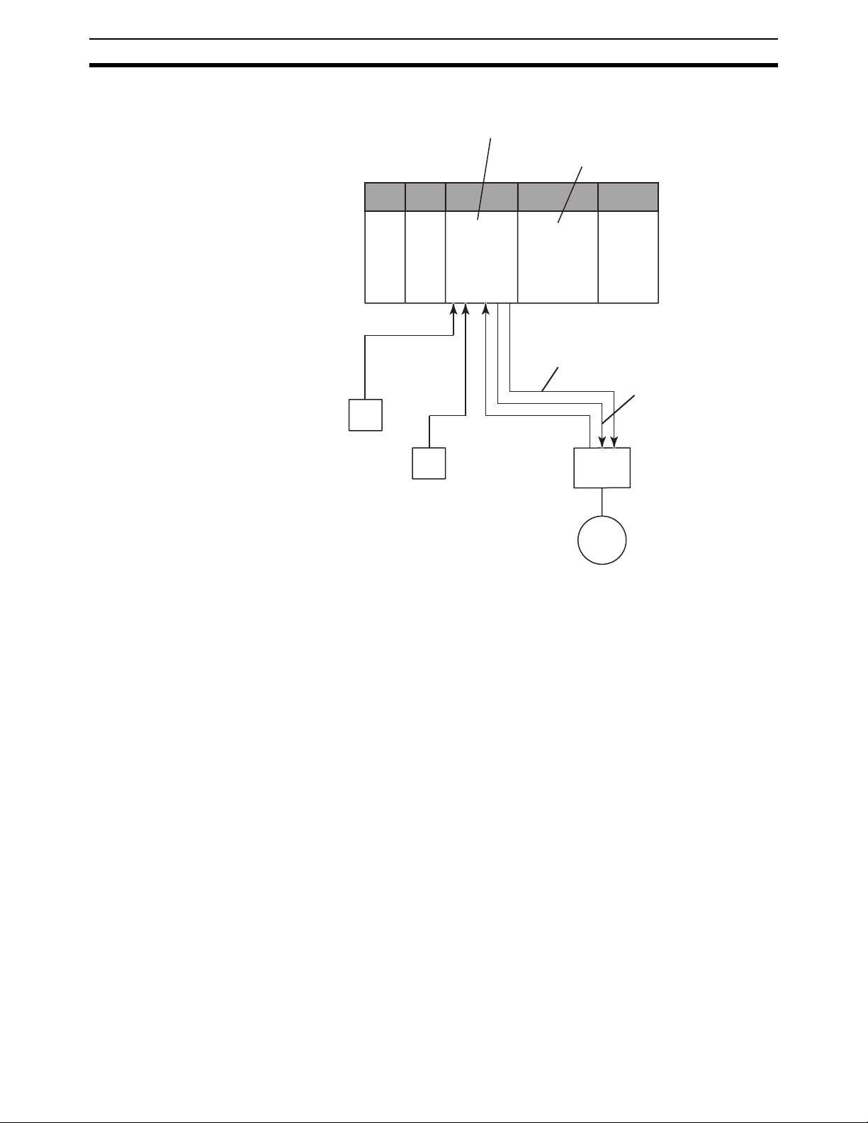
• Torque control (Clamping in molding applications, transfer control in injection-molding applications) (CS1W-HCA12-V1 only)
pressure control (speed control and torque limit)
• Using this unit with a servo driver of an analog input type and a pressure sensor enables the control as described below. Note that the servo driver (W series manufactured by OMRON in the example) is to be
in the "speed control" mode.
® Programming ® Contact Output:
® Program ® Pulse Output for CS1W-HCP22-V1
® Program ® Analog Output for CS1W-HCA22-V1
® Position control ®
® position control
7
Page 28
Outline Section 1-1
• System configuration
Customizable Counter Unit
CS1W-HCA12-V1
CS-series CPU Unit
ON/OFF
Position
detector
Pressure
sensor
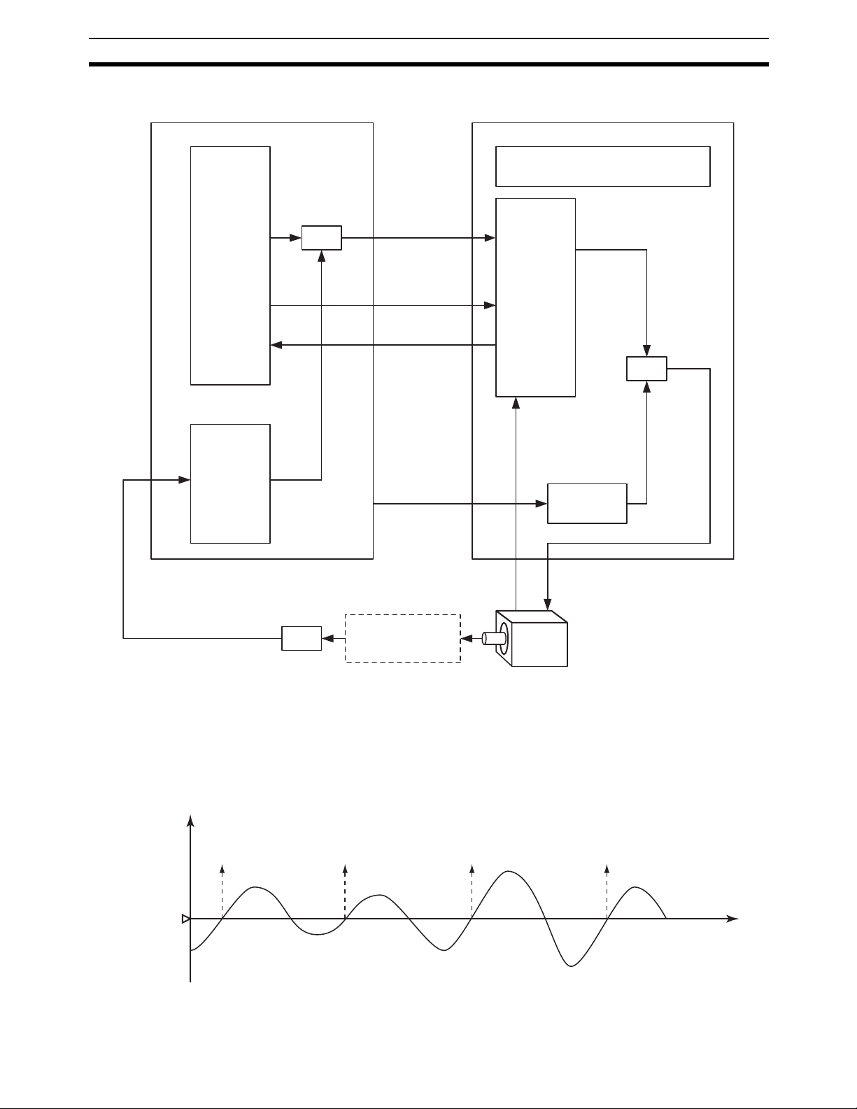
• Operation Process
1) Position control by the unit (CS1W-HCA12-V1):
A speed command is issued to the servo driver with the analog
output. The servo driver feeds back the absolute position information with the absolute encoder input. Using the feedback, position control is executed (through the speed command output)
following SPED or ACC instructions on the ladder program of the
unit.
2) Pressure control by the unit (speed control and torque limit):
Reaching a certain position (position for pressure control) causes the unit to output a speed and a torque limit command for the
speed control and torque limit. The pressure control (clamping
etc) is executed after the unit converts the analog inputs (load
cell, strain gauge, etc) from the pressure sensor to the analog
outputs (torque limit by the speed command and torque limit output) for the servo driver.
3) Position control by the unit
Once the operation (molding, etc) is completed, a speed command output from the unit returns the mechanical system to its
origin.
Analog input
(4 to 20 mA)
Analog output (−10 to +10 V):
Speed control
Analog output (0 to 10 V):
Torque limit)
Signal from
absolute encoder
Servo driver
Servo motor
8
Page 29
Outline Section 1-1
Customizable Counter Unit
CS1W-HCA12-V1
Position control,
or
Speed control
(SPED or ACC
instruction)
Pressure
control
switch
Analog output
(Speed control)
−10 to 10 V, etc.
SEN signal
Signal from
ABS encoder
Analog output
(Torque limit)
−10 to 10 V, etc.
Servo driver (Omron W-series)
Control mode:
Speed control (analog commands)
Speed control
+
Torque limit
Analog input
4 to 20 mA,
0 to 10 V etc.
Displacement
Count
Threshold
Absolute encoder signal
(line driver)
Pressure
sensor
Clamping
in pressing
Power cable
(U, V, W)
Servo motor
with
Absolute encoder
• Linear sensor control (control based on monitoring the ups and downs/
distortion/thickness/height/diameter of objects) (CS1W-HCA12-V1 only)
• Example) Counting ups and downs (piles)
With the use of a displacement sensor, the unit can count the number
of ups and downs (piles) by monitoring the change in the displacement
amount as the sensor measures them on the surface of objects moving at high speed.
1
23 4
Time
9
Page 30
Outline Section 1-1
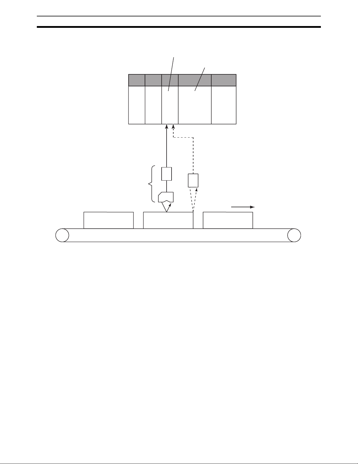
• System configuration
Customizable Counter Unit
CS1W-HCA12-V1
CS-series CPU Unit
4 to 20 mA
Displacement
Sensor
• Operation Process
ON/OFF
Photo-electric Switches
Moving at high speed
1) High-speed analog input (immediate refresh)
4 to 20 mA signals from the displacement sensor are input to and
refreshed in the unit at every PRV instruction execution. The displacement data is stored in the areas (Ex: DM) that have the I/O
memory.
2) Counting process with the ladder program
A ladder program has to be arranged (Ex: The unit compares the
ranges with BCMP instruction, and the unit counts rises of the results with INC instruction) so that the counter will count the number
of times of when the stored displacement data exceed a certain
threshold value. The execution of the program will make the unit
count.
10
Page 31

Outline Section 1-1
Customizable Counter Unit
CS1W-HCA12-V1
Ladder program
Displacement
Sensor
4 to 20 mA
Acquire the analog
input value by PRV
instruction (immediate refresh)
The unit compares the
ranges with BCMP
instruction, and the unit
counts rises of the results
with INC instruction
I/O memory
Displacement
Store
Count value
• Linear sensor control (High-speed trace of in-line quality data) (CS1WHCA12-V1 only)
• Example) Quality check of high-speed assembling process (injection
etc)
With the use of a displacement sensor, the sensor inputs the characteristic data of objects flowing at high speed, and the unit' data memory stores the input data at constant intervals.
a) The data can be transferred to the memory card by batch process-
ing, and can be read using the PC for analyses.
b) The data can be transferred to the CPU unit's data memory by
batch processing, and the line plot of the data can be displayed on
the screen of the programmable terminal (NS series by OMRON).
11
Page 32

Outline Section 1-1
r
• System configuration
NS series PT
Customizable Counter Unit
CS1W-HCA12-V1
CS-series CPU Unit
Memory card
Injection
Process
Displacement
Sensor
4 to 20 mA
ON/OFF
Photo-electric Switches
Moving at high speed
Store the line plot
Analyze
Personal compute
12
Page 33

Outline Section 1-1
• Operation Process
1) High-speed analog input by scheduled interrupts with the ladder
program (immediate refresh)
The PRV instruction is executed at each of constant executions of
subroutine programs with the scheduled interrupts (interval timer).
4 to 20 mA signals from the displacement sensor are input, refreshed, and stored (trace data) in the I/O memory area (Ex. DM)
of the main unit.
2) Transferring the traced data to the CPU unit
The data traced in the unit is transferred to the CPU unit. (Ex.
Through the cyclic transfer to DM allocated in the CPU unit)
3) Transferring the data to the memory card inserted in the slot of the
CPU unit
The data in the DM area is stored in the memory card as a data
file (.CSV etc) through the FWRIT instruction of the CPU unit.
4) Analysis performed on the spreadsheet software
Through the memory card adaptor connected to the PC, the data
file (.CSV etc) can be analyzed on the spreadsheet software.
5) Line plot displayed on PT (NS series)
The trace data in the CPU unit can be displayed as the line plot on
PT (NS series).
Customizable Counter Unit
CS1W-HCA12-V1
CS-series CPU Unit
Displacement
Sensor
4 to 20 mA
Ladder program Ladder program
Start the interval timer
by STIM instruction
Interrupt subroutines
SBN
Acquire the analog
input value by PRV
instruction (immediate
refresh)
RET
I/O memory
Traced data
Store
Displacement
value 1
Displacement
value 2
Displacement
value n
I/O memory
Allocated DM area
Refresh
Store the data to
memory card
PT (NS series)
Display
a line graph
Store
Memory card
13
Page 34

Models and System Configurations Section 1-2
1-2 Models and System Configurations
1-2-1 Models
There are three models of Customizable Counter Unit, all of which are classified as CS1 Special I/O Units.
Model number Functions
CS1W-HIO01-V1 12 contact inputs, 8 contact outputs
CS1W-HCP22-V1 12 contact inputs, 8 contact outputs, 2 pulse inputs, 2 pulse out-
puts
CS1W-HCA22-V1 12 contact inputs, 8 contact outputs, 2 pulse inputs, 2 analog out-
puts
CS1W-HCA12-V1 12 contact inputs, 8 contact outputs, 1 analog input, 1 pulse input
1-2-2 System Configurations
CS1W-HIO01-V1(Basic Model)
(compatible with servo drivers with absolute encoders), 2 analog
outputs
Programming
Device
CX-Programmer
Creating, transferring, and
monitoring the program for the
Customizable Counter Unit.
12 contact inputs, 4 of
which can be used as
interrupt inputs
8 contact outputs
CS1W-HIO01-V1
Customizable
Counter Unit
Peripheral port
Contact I/O
Ladder
program
I/O
memory
Peripheral Port Connecting Cable
(peripheral bus)
CS-series CPU Unit
Ladder
program
I/O
memory
OR
Programming
Console
14
Page 35

Models and System Configurations Section 1-2
CS1W-HCP22-V1 (Pulse Inputs and Pulse Outputs)
Programming
12 contact inputs, 4 of
which can be used as
interrupt inputs
CS1W-HCP22-V1
Customizable
Counter Unit
Device
Peripheral Port Connecting Cable
(peripheral bus)
CS-series CPU Unit
CX-Programmer
Creating, transferring, and
monitoring the program for
the Customizable Counter
Unit.
OR
Programming
Console
2 pulse inputs
(compatible with
servo drivers with
absolute encoders)
2 pulse outputs
8 contact outputs
Rotary encoder, etc.
Rotary encoder, etc.
Servodriver, etc.
Servodriver, etc.
Peripheral port
Contact I/O
Ladder
program
I/O
memory
Special I/O
Ladder
program
I/O
memory
15
Page 36

Models and System Configurations Section 1-2
CS1W-HCA22-V1 (Pulse Inputs and Analog Outputs)
CX-Programmer
Creating, transferring, and
monitoring the program for
the Customizable Counter
Unit.
OR
Programming
Console
12 contact inputs, 4 of
which can be used as
interrupt inputs
Programming
Device
CS1W-HCA22-V1
Customizable
Counter Unit
Peripheral Port Connecting Cable
(peripheral bus)
CS-series CPU Unit
8 contact outputs
2 pulse inputs
(compatible with
servo drivers with
absolute encoders)
2 analog outputs
Rotary encoder, etc.
Rotary encoder, etc.
Operation
terminal,
etc.
Operation
terminal,
etc.
Peripheral port
Contact I/O
Ladder
program
I/O
memory
Special I/O
Ladder
program
I/O
memory
CS1W-HCA12-V1 (Analog Inputs, Pulse Input and Analog Outputs)
Programming
Device
CS1W-HCA12-V1
Customizable
Counter Unit
Peripheral Port Connecting Cable
(peripheral bus)
CS-series CPU Unit
CX-Programmer
Creating, transferring, and
monitoring the program for
the Customizable Counter
Unit.
OR
Programming
Console
16
12 contact inputs, 4 of
which can be used as
interrupt inputs
8 contact outputs
1 analog inputs
1 pulse inputs
(compatible with
servo drivers with
absolute encoders)
2 analog outputs
Sensor inputs
(Pressure,
displacement,
etc.)
Rotary encoder, etc.
Operation
terminal,
etc.
Operation
terminal,
etc.
Peripheral port
Contact I/O
Ladder
program
I/O
memory
Special I/O
Ladder
program
I/O
memory
Page 37

Models and System Configurations Section 1-2
Programming Devices
The CX-Programmer versions that can be used with the Customizable
Counter Unit are given in the following table.
Name Model number Computer Serial communications
CX-Programmer
Ver. 1.2 or later
(on CD-ROM)
WS02-CXPC1-E IBM PC/AT or compatible
The Programming Consoles that can be used with the Customizable Counter
Unit are given in the following table.
Model number Cable
C200H-PRO27 CS1W-CN224 or CS1W-CN624 required separately.
CQM1-PRO01 2-m cable provided with Programming Console, but CS1W-N114
CQM1H-PRO01 2-m cable provided with Programming Console
Connecting Contact and Special I/O
Special connectors are required to connect the contact I/O and special I/O to
the connectors on the Customizable Counter Unit. These connectors are provided with the Customizable Counter Unit and can be purchased separately.
The cables for these connectors must be provided and wired to the connectors by the user. An OMRON Connector–Terminal Block Conversion Unit can
also be used for the special I/O. Refer to 3-3 Wiring for details.
mode
Peripheral bus CQM1H-CPU61
OS: Microsoft Windows
95 or 98
Model setting on the
CX-Programmer
Note There are some functional limitations in using the CX-Programmer
with the Customizable Counter Unit. Refer to 3-4 Programming Devices for details.
required separately.
17
Page 38

Models and System Configurations Section 1-2
18
Page 39

SECTION 2
Specifications
This section provides performance specifications and I/O specifications for the Customizable Counter Unit.
2-1 Performance Specifications . . . . . . . . . . . . . . . . . . . . . . . . . . . . . . . . . . . . . . 20
2-1-1 Available Models . . . . . . . . . . . . . . . . . . . . . . . . . . . . . . . . . . . . . . . 20
2-1-2 Specifications . . . . . . . . . . . . . . . . . . . . . . . . . . . . . . . . . . . . . . . . . . 20
2-1-3 Program and Memory . . . . . . . . . . . . . . . . . . . . . . . . . . . . . . . . . . . 22
2-1-4 Functions . . . . . . . . . . . . . . . . . . . . . . . . . . . . . . . . . . . . . . . . . . . . . 25
2-1-5 I/O Specifications. . . . . . . . . . . . . . . . . . . . . . . . . . . . . . . . . . . . . . . 28
2-2 Contact I/O Specifications (All Units) . . . . . . . . . . . . . . . . . . . . . . . . . . . . . . 33
2-2-1 Contact I/O Specifications . . . . . . . . . . . . . . . . . . . . . . . . . . . . . . . . 33
2-2-2 I/O Connector Pin Arrangement . . . . . . . . . . . . . . . . . . . . . . . . . . . 34
19
Page 40

Performance Specifications Section 2-1
2-1 Performance Specifications
2-1-1 Available Models
Model number Program
capacity
CS1W-HIO01-V1 4 Kwords 12 inputs
CS1W-HCP22V1
CS1W-HCA22V1
CS1W-HCA12V1
I/O points (built-in) Special I/O Built-in
Contact
input
(24 VDC)
(4 inputs
can be
used as
interrupt
inputs)
Contact
output
8 transistor
outputs
(sinking)
Pulse input (high-
speed counters)
Compatible
with servo
driver with
absolute
encoder
(See note)
None No None None None For Pro-
2 pts Yes 2 pts None None
2 pts Yes None 2 pts None
1 pts Yes None 2 pts 1 pts
Pulse
outputs
Analog
outputs
Analog
inputs
peripheral
gramming
Console or
CX-Programmer
Note Supported only by lot numbers of 0209__ or higher.
2-1-2 Specifications
Item Specification
Model number CS1W-HIO01-V1/CS1W-HCP22-V1/CS1W-HCA22-V1/CS1W-
Unit classification CS1 Special I/O Unit
Applicable PLCs CS-series PLCs
Applicable unit numbers 00 to 95 (Must not be duplicated with other Special I/O Units)
Applicable Rack/slot CS-series CPU Rack or Expansion Rack
HCA12-V1
port
Exchange of
specific data
with CPU Unit
Special I/O Unit Area
(CIO n to n+9;
n = 2000 + (unit number ´ 10))
DM Area words allocated to Special I/O Units (m to m+99;
m = D20000 + (unit number ´ 99))
Initial settings
from the CPU
Unit
Area for
exchanging
general-purpose data with
the CPU Unit
Note
10 words per Unit (data exchanged constantly)
5 words: CPU Unit ® Customizable Counter Unit (RUN/STOP commands, general-purpose output data)
5 words: Customizable Counter Unit ® CPU Unit (Unit status, general-purpose input data)
100 words per Unit
10 words: System Setup Area (transferred from the CPU Unit to the
Customizable Counter Unit at startup or Unit restart).
The System Setup Area contains the following settings: Enable/disable of RUN/STOP command from the CPU Unit; startup operating
mode; specification of beginning word addresses for the output and
input areas for data exchange with the CPU Unit; number of
exchange words; the area used as the data exchange area in the
Customizable Counter Unit; address specifications, etc.
90 words: For exchanging the general-purpose data listed below.
1. There are no restrictions on the mounting slot.
2. Mounting to C200H Expansion Racks or SYSMAC
BUS Slave Racks is not possible.
20
Page 41

Performance Specifications Section 2-1
Item Specification
Exchange of
general-purpose data with
CPU Unit
Methods for making Customizable Counter Unit’s
initial settings
Mounting method Rack mounting
Setting switches Rotary switches on front panel: Unit number (0 to 95)
Display 25 LED indicators
Front panel
connections
Super-capacitor backup data (in RAM) DM Area (DM 0000 to DM 6143), EM Area (EM 0000 to EM 2047)
Continuous data exchange
between words in the SR Area in
the Customizable Counter Unit
and CIO Area allocated words in
the CPU Unit
Continuous data exchange
between user-set words in the
Customizable Counter Unit and
words allocated in the CPU Unit’s
DM Area
Continuous data exchange
between LR Area words in the
Customizable Counter Unit and
user-set words in the CPU Unit
All models
(CS1W-HIO01-V1/HCP22-V1/
HCA22-V1/HCA12-V1)
CS1W-HCP22-V1/HCA22-V1/
HCA12-V1 only
4 input words and 4 output words (Inputs are to Customizable
Counter Unit)
I/O refresh is performed between words in the Customizable
Counter Unit’s SR Area (SR 231 to SR 234 and SR 236 to SR 239)
and words allocated in the CPU Unit’s CIO Area.
90 words max.
I/O refresh is performed for up to 90 words between user-set words
in the Customizable Counter Unit and words allocated in the CPU
Unit’s DM Area.
Note Both inputs and outputs can be set in Customizable Counter
Unit’s DM, AR, IR, LR, and EM Areas.
32 words max.
I/O refresh is performed for up to 32 words between the Customiz-
able Counter Unit’s LR Area (in the order inputs ® outputs) and
user-set words in the CPU Unit.
Note Both inputs and outputs can be set in CPU Unit’s CIO, WR,
AR, HR, DM, and EM Areas.
1. Using the initial settings in the first 10 words (m to m+9) of the
words allocated in the CPU Unit’s DM Area
2. Using the Unit Setup Area (DM 6600 to DM 6655) of the Cus-
tomizable Counter Unit
Toggle switch: Programming Device connection switch (enables/disables servicing for the Programming Device connected to the
peripheral port)
The Unit is equipped with the following indicators: RUN (Unit operation), OPN (Unit program running), ERC (Unit error), ERH (CPU
Unit error), COMM (peripheral communications), In0 to In11 (for
inputs), and Out0 to Out7 (for outputs).
• One peripheral port (for Programming Device)
• One I/O connector (Compatible connector: FCN-361J024-AU
(socket) and FCN-360C024-J2 (connector cover) made by
Fujitsu)
In addition to the above, one special I/O connector (Compatible connector: FCN-361J040-AU (socket) and FCN-360C040-J2 (connector cover) made by Fujitsu)
(See note 1.), Error Log Area (DM 6144 to DM 6199), counter
present values
Note
Flash memory data User program, general-purpose read-only portion of DM Area
(DM 6200 to DM 6599), Unit Setup Area (DM 6600 to DM 6655),
expansion instruction information (Also DM 0000 to DM 6143)
Super-capacitor backup time 10 days at 25°C
Self-diagnosis function CPU errors (WDT), memory errors, FALS system errors (FALS
instruction execution or maximum cycle time exceeded), FAL system errors (FAL instruction execution, Unit Setup Area errors, etc.),
cycle time exceeded 10 ms, communications port errors, etc.
1. It is possible to set whether EM Area data is held or not
(with the default setting, data is cleared).
2. If the power supply to the PLC is left OFF for longer
than the super-capacitor’s backup (saving) time, the
above data will be lost. Therefore, before turning OFF
the CPU Unit’s power supply for an extended period of
time, save the data using the ladder program. (Data
memory can be saved to flash memory.)
21
Page 42

Performance Specifications Section 2-1
Item Specification
Effect on CPU Unit’s cycle time • When data exchange is performed using the words allocated in
Internal current consumption CS1W-HIO01-V1: 600 mA at 5 VDC
Dimensions 34.5 ´ 130 ´ 100.5 mm (W ´ H ´ D)
Weight CS1W-HIO01-V1: 250 g max.
Standard accessories CS1W-HIO01-V1
the CIO Area only: 0.2 ms
• When data exchange is performed using words allocated in the
DM Area or the LR Area: 0.5 ms
CS1W-HCP22-V1: 800 mA at 5 VDC
CS1W-HCA22-V1: 750 mA at 5 VDC, 150 mA at 26 VDC
CS1W-HCA12-V1: 750 mA at 5 VDC, 150 mA at 26 VDC
CS1W-HCP22-V1/HCA22-V1/HCA12-V1: 350 g max.
One OMRON C500-CE241 Connector Set for connecting to I/O
connector (soldered type; socket: FCN-361J024-AU made by
Fujitsu; connector cover: FCN-360C024-J2 made by Fujitsu)
CS1W-HCP22-V1/HCA22-V1/HCA12-V1
In addition to the above, one C500-CE404 Connector Set (made by
OMRON) for connecting to special I/O connector (soldered type;
socket: FCN-361J040-AU made by Fujitsu; connector cover: FCN360C040-J2 made by Fujitsu)
2-1-3 Program and Memory
Item Specifications
Control method Stored program
I/O control method Cyclic scan and immediate processing are both possible.
Customizable Counter Unit operating modes RUN mode, MONITOR mode, PROGRAM mode
RUN/STOP specification method for Customiz-
able Counter Unit’s program
Status output to CPU Unit Unit’s operating mode (RUN/STOP), fatal errors, CYCLE TIME OVER
Compatible Programming Devices Programming Console (C200H-PRO27 or CQM1H-PRO01) or CX-
Programming language Ladder diagram
Execution modes Possible to switch between Normal Execution Mode and High-speed
Program capacity 4 Kwords (Normal Execution Mode)
Instruction length 1 to 4 words per instruction
Number of instructions 113 (14 basic instructions and 99 special instructions)
Instruction exe-
cution time
Basic instructions Normal Execution Mode: 0.4 ms (LD instruction)
Special instructions Normal Execution Mode: 4.8 ms (MOV instruction)
Select between the following:
1. RUN/STOP commands from the CPU Unit’s allocated memory
2. Operating mode command at startup, or command from the Programming Device after startup
errors, Unit error codes, etc.
Programmer Ver. 1.2 or later (Specify CQM1H as the PLC type. There
are restrictions, such as the program capacity.)
Execution Mode.
• Normal Execution Mode: 0.4 ms for LD instruction
• High-speed Execution Mode: 0.2 ms for LD instruction
Note In High-speed Execution Mode, the capacity for which execu-
tion (compiling) is possible is restricted. Also, whether or not
programs can be executed depends on the contents of the program. The average program capacity in High-speed Execution
Mode is approx. 1 Kword.
High-speed Execution Mode: 0.2 ms (LD instruction)
High-speed Execution Mode: 4.4 ms (MOV instruction)
22
Page 43

Performance Specifications Section 2-1
Item Specifications
Common processing (overhead) CS1W-HIO01-V1: 0.08 ms max.
I/O allocations None (The Unit’s built-in I/O points are used for the Input and Output
CS1W-HCP22-V1/HCA22-V1/HCA12-V1: 0.1 ms max.
The above figures are for operation under the following conditions:
1. Data exchange with the CPU Unit is performed using the allocated
words in the CIO Area only.
2. The Programming Device connection switch is set to OFF.
3. With the HCP22-V1/HCA22-V1/HCA12-V1, Measurement Mode
is not being used.
4. With the HCA22-V1, analog output is disabled.
5. With the HCA12-V1, analog input is refreshed immediately, and
analog output is disabled.
Areas given below.)
23
Page 44

Performance Specifications Section 2-1
Item Specifications
I/O memory Input Area 12 bits: IR 000 (IR 00000 to IR 00011)
Output Area 8 bits: IR 001 (IR 00100 to IR 00107)
Work Area 1,088 bits (68 words): IR 002 to IR 049 (IR 00200 to IR 04915), IR 200
SR Area 568 bits (36 words): SR 220 to SR 255 (SR 22000 to SR 25507)
AR Area 448 bits (28 words): AR 00 to AR 27 (AR 0000 to AR 2715)
TR Area 8 bits: TR 0 to TR 7
LR Area 512 bits (32 words): LR 00 to LR 31
Timer/Counter Area 256 points: TIM/CNT 000 to TIM/CNT 255 (The same numbers are
DM Area
(general-purpose read/write
area)
EM Area 2,048 words: EM 0000 to EM 2047
The Unit’s built-in input points are allocated to these bits (fixed allocations).
Note IR 00000 to IR 00003 can be used either as normal input bits
or for interrupt inputs (in Input Interrupt Mode or Counter
Mode).
The Unit’s built-in output points are allocated to these bits (fixed allocations).
to IR 219 (IR 20000 to IR 21915)
These bits have no specific functions and can only be used in the program.
These bits have specific functions.
Note SR 230 to SR 234 and words SR 235 to SR 239 are used for
exchanging general-purpose data with the CPU Unit.
These bits have specific functions.
These bits temporarily store the ON/OFF status of an instruction block
for branching.
These bits are for exchanging general-purpose data with the CPU
Unit. (Data can be exchanged cyclically with user-set words in the
CPU Unit. Up to 32 words of data can be input or output. The word
allocation are specified in the Unit Setup Area.)
used for timers and counters.)
When using the CNT and CNTR instructions, at power interruption or
when the mode is switched, present counter values are held (with
super-capacitor backup) at the values immediately before power was
interrupted or the mode was switched. When other instructions are
used, the data in the TIM/CNT Area is cleared.
6,144 words: DM 0000 to DM 6143
Data in this area can be read or written in word (16-bit) units. It is held
(with super-capacitor backup) at power interruptions or when the
mode is switched. Writing can be performed with instructions or from
the Programming Device.
Note By turning ON bit SR 25200, it is possible to save all the data in
the range DM 0000 to DM 6143 to flash memory. The data is
read using the XFER instruction.
Data in this area can be read or written in word (16-bit) units. It is possible to specify whether the data is held (with super-capacitor backup)
at power interruptions or when the mode is switched. Writing can be
performed with instructions or from the Programming Device.
24
Page 45

Performance Specifications Section 2-1
Item Specifications
Other memory
areas
Trace memory None
Read-only portion of DM
Area
Error Log Area 56 words: DM 6144 to DM 6199
General-purpose read-only
area
Unit Setup
Area
Data in this area is held (with super-capacitor backup) at power interruptions or when the mode is switched.
400 words: DM 6200 to DM 6599
Data in this area is held (in flash memory) at power interruptions or
when the mode is switched.
Writing to this area is not possible using instructions; it is only possible
from the Programming Device. (Reading is possible with either
method.) Data in this area is protected from being changed by the ladder program.
56 words: DM 6600 to DM 6655
This area is for making the initial settings for the functions of the Customizable Counter Unit at a software level.
Data in this area is held (in flash memory) at power interruptions or
when the mode is switched.
Writing to this area is not possible using instructions; it is only possible
from the Programming Device. (Reading is possible with either
method.) Data in this area is protected from being changed by the ladder program.
2-1-4 Functions
Types of interrupts
Item Specifications
Input interrupts
(4 points max.)
Interval timer
interrupt (1
point)
CS1W-HCP22V1 (pulse I/O)
CS1W-HCA22V1/HCA12-V1
(pulse inputs
and analog outputs)
Input Interrupt Mode Interrupt is executed in response to
Counter Mode Interrupt is executed after input is
Scheduled Interrupt Mode Program is interrupted at regular intervals measured by
One-shot Interrupt Mode Program is interrupted once after a certain time measured
Pulse inputs
(high-speed
counter)
Pulse outputs
Pulse inputs
(high-speed
counter)
Target value
interrupts
Target value
interrupts
Target value
interrupts
input to the Unit’s built-in input points
(input bits 00000 to 00003). Interrupts
can be executed when the corresponding input turns ON, OFF, or
both. The response time between the
input conditions being satisfied and
execution of the interrupt program is
0.08 ms (for execution at ON).
received via the Unit’s built-in input
points a certain number of times. The
number of times is counted decrementally when the corresponding input
turns ON, OFF, or both.
one of the Unit’s internal timers.
by one of the Unit’s internal timers.
Interrupt is executed when the high-speed counter PV is
equal to a target value set with the CTBL instruction.
Interrupt is executed when the pulse output PV is equal to
a target value set with the CTBL instruction.
Interrupt is executed when the high-speed counter PV is
equal to a target value set with the CTBL instruction.
Note 1:
Specify the mode
as either Input
Interrupt Mode or
Counter Mode
using the INT
instruction.
Note 2:
Specify ON, OFF,
or both in the Unit
Setup Area.
25
Page 46

Performance Specifications Section 2-1
Item Specifications
Bit pattern output for comparison
Functions Execution of CPU Unit’s external interrupt
CS1W-HCP22V1 (pulse I/O)
CS1W-HCA22V1/HCA12-V1
(pulse inputs
and analog outputs)
tasks
Constant cycle time A constant cycle time can be set in the range 0.1 to 50 ms
Cycle time monitoring If the cycle time exceeds 10 ms, the Cycle Time Over Flag
I/O refreshing Cyclic refreshing, immediate refreshing by IORF
I/O memory holding when changing operating modes
Mode setting at power-ON Possible (Specified in the allocated words of the DM Area.)
MCRO instruction Calling of subroutines and passing arguments and execut-
Debugging Differential monitoring
Online editing User programs can be overwritten in program-block units
User memory
(UM) protection
Pulse input
(high-speed
counter)
Pulse output Range com-
Pulse input
(high-speed
counter)
Program protection In the Unit Setup Area, it is possible to prohibit writing to
Range comparison bit
pattern output
parison bit
pattern output
Range comparison bit
pattern output
A specified bit pattern is output when the high-speed
counter PV lies within a range specified with the CTBL
instruction.
A specified bit pattern is output when the pulse output PV
or the pulse counter PV (measurement time) lies within a
range specified with the CTBL instruction.
A specified bit pattern is output when the high-speed
counter PV lies within a range specified with the CTBL
instruction.
The CPU Unit’s external interrupt tasks (task numbers 0 to
99) can be executed from the Unit using the MCRO
instruction in the Unit’s program.
(in 0.1-ms units).
Using this function, even if all the necessary processing is
completed in less than the set time, the next cycle will not
start until the constant cycle time setting has elapsed. (If
the constant cycle time is exceeded, the Constant Cycle
Time Exceeded Flag turns ON.)
(SR 23509) turns ON, and operation continues. (This function can be turned OFF in the Unit Setup Area.)
When the cycle time exceeds the cycle monitor time, operation stops. The cycle monitor time can be set in the range
1 to 100 ms in 1-ms units (default setting: 50 ms).
Note The cycle time’s maximum value and present value
are stored in the AR Area.
CS1W-HCA22-V1/HCA12-V1 only: Immediate refreshing
of analog output values
Note It is not possible to set immediate refreshing for
each instruction.
Not possible.
ing CPU Unit’s external interrupt tasks
when the CPU Unit is in MONITOR mode. With the CXProgrammer, more than one program-block can be edited
at the same time.
Note During overwriting using online editing, the Unit
cannot perform operations and the program will be
interrupted for 1,200 ms max.
the user program, the general-purpose read-only portion
of DM Area, the Unit Setup Area, and expansion instruction information from the Programming Device.
26
Page 47

Performance Specifications Section 2-1
Item Specifications
Functions
(continued)
Self-diagnosis User-defined self-diagnosis are possible (fatal errors and
Error log Up to 11 errors (including user-defined errors) can be
Serial communications port One built-in peripheral port: Used for connecting Program-
Serial communications modes Application Built-in peripheral
Programming Console bus Used for communications with Pro-
Peripheral bus Used for communications with Pro-
Clock None
Output OFF function None
Forced set/reset Available (When switching between PROGRAM mode and
Memory protection at power interruption Held areas: DM Area (general-purpose read/write area),
Program check Program checks are always performed at the beginning of
Analog inputs (CS1W-HCA12-V1 only) High-speed input (with 50 ms of A/D conversion) of analog
Compatible with servo driver with absolute
encoder (CS1W-HCP22-V1/HCA22-V1/
HCA12-V1 only)
non-fatal errors can be defined using user instructions
(FALS/FAL instructions)).
Note Operation can also be stopped automatically using
user-defined fatal error instructions. User-defined
logging in specific bits is also possible using userdefined non-fatal error instructions.
recorded in the Error Log Area (DM 6145 to DM 6199).
The information recorded includes the error code, the error
details, and the time the error occurred.
Special I/O Unit error codes are stored in the Error Log
Area.
Unit error codes (SR 23500 to SR 23507) are stored in bits
00 to 07 of the error details in the Error Log Area.
ming Device (peripheral bus, Programming Console)
port
Ye s
gramming Console
Ye s
gramming Devices such as CX-Programmer
Note The time of error occurrence that is recorded in the
error log will depend on the time in the CPU Unit. If
it is not possible to access the time in the CPU
Unit, 0 will be recorded.
Note The outputs from the Unit can be turned OFF from
the program when the outputs in the CPU Unit are
turned OFF. This operation must be programmed
by the user. Refer to 4-1 Overview for details.
RUN or MONITOR mode or when the power is turned ON,
the forced set/reset status is cleared.)
Note There is a part of the AR Area where forced set/
reset is possible. For details on the AR Area, refer
to 6-4 AR Area.
EM Area, and present counter values
Note It is possible to specify whether the EM Area is held
or not in the Unit Setup Area.
operation for items such as no END instruction and
instruction errors. It is also possible to check programs
from the CX-Programmer. (The check level can also be
set.)
data is possible. This makes the unit compatible with applications that require high-speed processing such as displacement sensor input.
Data (the number of turns) of servo driver (W series by
OMRON, etc.) with ABS encoder (multi-turn absolute
encoder) can be input (to phase A).
Note Supported only by lot numbers of 0209__ or higher.
27
Page 48

Performance Specifications Section 2-1
Item Specifications
Functions
(continued)
Ladder library (-V1 only) It is possible to encapsulate the entire program or the part
of subroutine programs, and to save it to the Flash memory in the unit as the ladder library. The saved library can
be executed by the following methods:
• Call the library to execute at starting operations (Boot
mode)
• Call it to execute with MCRO instruction (MCRO mode)
Back-up function (-V1 only) It is possible to back up and restore the contents of the unit
back-up memory (user program, unit setup area, ladder
library, etc.) to the memory card as the unit back-up file
thru the simplified back-up operation on CPU unit's front
panel or the bit operation on this unit.
Constant cycle time refresh (-V1 only) At the occurrence of CONSTANT CYCLE TIME OVER
error with the use of the constant cycle time function, the
error can be cleared by the bit operation on the ladder program and the cycle time can be put back to constant continuously again.
2-1-5 I/O Specifications
■ All Units: CS1W-HIO01-V1, CS1W-HCP22-V1, CS1W-HCA22-V1 and CS1W-
HCA12-V1
Contact Inputs
Item Contents
Number of inputs 12 inputs (bits IR 00000 to IR 00011)
Details:
• 4 interrupt inputs in Input Interrupt Mode or Counter
Mode. Can also be used as normal inputs (bits IR 00000
to IR 00003)
• 8 normal inputs (bits IR 00004 to IR 00011)
Note It is possible to specify ON, OFF, or both for the tim-
ing of interrupts in Input Interrupt Mode.
Input signal type 24-VDC
Contact Outputs
Item Contents
Number of outputs 8 outputs (bits IR 00100 to IR 00107)
Output signal type Transistor NPN outputs
28
Page 49

Performance Specifications Section 2-1
■ CS1W-HCP22-V1 (Pulse I/O)
Pulse Inputs (High-speed Counters)
Item Contents
Number of counters 2
Counting mode • Linear Mode
•Ring Mode
Modes compatible with absolute encoders (Supported only
by lot numbers of 0209__ or higher)
• ABS linear (CW-) counter
• ABS linear (CW+) counter
• ABS ring mode counter
(Set in Unit Setup Area (DM 6605).)
Signals A and B and pulse input Z
Input method Differential-phase; x1
Differential-phase; x2
Differential-phase; x4
Increment/decrement
Pulse + direction
Compatible encod-
ers
Input voltage 5 VDC, 12 VDC, 24 VDC, RS-422A line driver (AM26LS31)
Output compatible
with absolute
encoder
(SEN signal)
Counter frequency 50 kHz (default) or 200 kHz
Control method Target value comparison
Measurement mode High-speed counter rate of change for port 1 or 2
Applicable Instructions
• Incremental encoders
• Absolute encoders (on servo drivers)
(When not using the functions compatible with servo drivers
with absolute encoders, using this unit as a normal counter
enables the incremental encoder input.)
When SEN signal is output to servo driver, servo driver will
transmit the number of encoder's rotations to this unit. After
that, it transmits pulse train corresponding to displacement
of the turns to the unit (transmit the same pulse as incre-
mental encoders).
(OMNUC W series servo driver by OMRON, etc.)
• 5 V PNP output
Range comparison
High-speed frequency for port 1
CTBL, INI, PRV(62)
PV can be compared, changed, and read with CTBL, INI, or
PRV.
Pulse Outputs
Item Contents
Number of outputs 2 outputs
Output
type
Single-phase
pulse output
One-shot
pulse outputs
Pulse output
counter time
(time measurement)
The single-phase pulse outputs can be used for positioning or speed control at a fixed duty ratio (duty ratio: 50%).
Output frequencies: 6 Hz to 200 kHz
Output can be set to turn ON for a time specified by the
user. (Set in range 0.01 to 9,999 ms in 0.01-ms units.)
High-precision timer measurement in 0.01-ms units is
possible using one-shot pulse output. (In this case, external pulse output is not possible.)
29
Page 50

Performance Specifications Section 2-1
■ CS1W-HCA22-V1 (Pulse Inputs and Analog Outputs)
Pulse Inputs (High-speed Counters)
same as CS1W-HCP22-V1
Analog Outputs
Item Contents
Number of outputs 2 outputs
Output signal ranges Each output can be set to any one of the following: 1 to 5 V,
Accuracy ±0.3%
Resolution –10 to 10 V: 1/10,000
D/A conversion time 0.05 ms max.
Output function
validity
Output hold mode Analog output values can be held. (Analog values can be
Analog output
refresh method
Offset/gain adjustment
Applicable Instructions
0 to 5 V, 0 to 10 V, or –10 to 10 V
0 to 10 V, 0 to 5 V, or 1 to 5 V: 1/4,000
Each analog output can be set whether output is valid or
invalid.
output at their peak, held, or cleared values when the Conversion Enable Flag is OFF, a fatal error occurs, or an analog output error occurs.)
Refreshing of analog outputs is set to one of the following:
END refresh
Immediate refresh via instructions
The offset or gain can be specified and changed.
Analog output can be controlled directly with SPED and
ACC.
30
Page 51

Performance Specifications Section 2-1
■ CS1W-HCA12-V1 (Pulse Inputs, Analog Inputs and Analog Outputs)
Pulse Inputs (Compatible with Servo Drivers with Absolute Encoders)
Item Contents
Number of counters 1
Counting mode • Linear Mode
•Ring Mode
Modes compatible with absolute encoders(Supported only
by lot numbers of 0209__ or higher)
• ABS linear (CW-) counter
• ABS linear (CW+) counter
• ABS ring mode counter
(Set in Unit Setup Area (DM 6605).)
Signals A and B and pulse input Z
Input method Differential-phase; x1
Differential-phase; x2
Differential-phase; x4
Increment/decrement
Pulse + direction
Compatible encod-
ers
Input voltage 5 VDC, 12 VDC, 24 VDC, RS-422A line driver (AM26LS31)
Output compatible
with absolute
encoder
(SEN signal)
Counter frequency 50 kHz (default) or 200 kHz
Control method Target value comparison
Measurement mode High-speed counter rate of change
Applicable Instructions
• Incremental encoders
• Absolute encoders (on servo drivers)
(When not using the functions compatible with servo drivers
with absolute encoders, using this unit as a normal counter
enables the incremental encoder input.)
When SEN signal is output to servo driver, servo driver will
transmit the number of encoder's rotations to this unit. After
that, it transmits pulse train corresponding to displacement
of the turns to the unit (transmit the same pulse as incre-
mental encoders).
(OMNUC W series servo driver by OMRON, etc.)
• 5 V PNP output
Range comparison
High-speed frequency
CTBL, INI, PRV(62)
PV can be compared, changed, and read with CTBL, INI, or
PRV.
Analog Input
Item Contents
Number of inputs 1
Input signal range One of the following ranges can be selected for each input:
-10 to +10 V, 0 to 10 V, 1 to 5 V/4 to 20 mA, or 0 to 5 V.
Resolution Varies depending on the range
-10 to +10 V: 1/16,000 (14 bits)
0 to 10 V: 1/8,000 (13 bits)
0 to 5 V: 1/4,000 (12 bits)
1 to 5 V: 1/4,000 (12 bits)
4 to 20 mA: 1/4,000 (12 bits)
31
Page 52

Performance Specifications Section 2-1
Item Contents
Accuracy • Voltage input
±0.2% (23±2°C)
±0.4% (0 to 55°C)
• Current input
±0.4% (23±2°C)
±0.6% (0 to 55°C)
A/D conversion time 0.05 ms max.
Input response time 1.5 ms or less (See Specification of Analog Input Functions
Output hold mode Analog output values can be held. (Analog values can be
Analog input refresh
method
Offset/gain adjustment
Applicable Instructions
on page 155 for details.)
output at their peak, held, or cleared values when the Conversion Enable Flag is OFF, a fatal error occurs, or an analog output error occurs.)
Refreshing of analog outputs is set to one of the following:
END refresh
Immediate refresh via instructions
The offset or gain can be specified and changed.
Analog input value can be read directly with PRV.
Analog Outputs
Item Contents
Number of outputs 2 outputs
Output signal ranges Each output can be set to any one of the following: 1 to 5 V,
Accuracy ±0.3%
Resolution –10 to 10 V: 1/10,000
D/A conversion time 0.05 ms max.
Output function
validity
Output hold mode Analog output values can be held. (Analog values can be
Analog output
refresh method
Offset/gain adjustment
Applicable Instructions
0 to 5 V, 0 to 10 V, or –10 to 10 V
0 to 10 V, 0 to 5 V, or 1 to 5 V: 1/4,000
Each analog output can be set whether output is valid or
invalid.
output at their peak, held, or cleared values when the Conversion Enable Flag is OFF, a fatal error occurs, or an analog output error occurs.)
Refreshing of analog outputs is set to one of the following:
END refresh
Immediate refresh via instructions
The offset or gain can be specified and changed.
Analog output can be controlled directly with SPED and
ACC.
32
Page 53

Contact I/O Specifications (All Units) Section 2-2
2-2 Contact I/O Specifications (All Units)
2-2-1 Contact I/O Specifications
Item Specifications
Contact
inputs
Number of inputs 12 inputs
• 4 inputs (input bits IR 00000 to IR 00003) can be used either as interrupt inputs or
normal inputs.
Note Each of these 4 inputs can be set to be used as either interrupt inputs or normal
inputs in the Unit Setup Area (DM 6620). It is also possible to specify the ON,
OFF, or both for the interrupt timing for each point (Input Interrupt Mode or
Counter Mode) in the Unit Setup Area (DM 6620).
• 8 inputs (input bits IR 00004 to IR 00011) can be used as normal inputs only.
Input voltage/current
24 V
+10%
/
, 5 mA typical
–15%
Min. ON voltage 15.2 V
Max. OFF voltage 4.8 V
Input response Inputs for interrupt input or normal input (4 points with one common):
ON delay time: 50 ms
OFF delay time: 200 ms max.
Inputs for normal input (8 points with one common):
ON delay time: 100 ms
OFF delay time: 1 ms max.
Circuit configura-
Customizable Counter Unit
tion
Interrupt inputs
Normal inputs
4.7 kΩ
4.7 kΩ
750 Ω
750 Ω
Internal circuit
Internal circuit
Input
indicator
Input
indicator
33
Page 54

Contact I/O Specifications (All Units) Section 2-2
Item Specifications
Contact
outputs
Number of outputs 8 outputs (used as normal outputs only)
Output type Sinking (NPN)
Switching capacity 4.5 to 30 VDC, 0.3 A per output
Maximum inrush
current
Leakage current 0.1 mA max.
Residual voltage 0.4 V max.
ON delay time 0.1 ms max.
OFF delay time 1 ms max.
External power
supply
Circuit configura-
tion
3.0 A per point, 10 ms max.
4.5 to 26.4 VDC
Customizable Counter Unit
+V
OUT00
to
OUT07
Internal circuit
Output
indicator
Note Information on input interrupts applies to both Input Interrupt Mode and
Counter Mode. Only single-phase inputs are possible for interrupt inputs.
2-2-2 I/O Connector Pin Arrangement
Pin arrangement Row B Pin Row A
External input 0 (Interrupt input or
normal input; bit 00000)
External input 1 (Interrupt input or
normal input; bit 00001)
Common for external inputs 0 to 3 10 Common for external inputs 4 to 11
External input 4
(Normal input; bit 00004)
External input 5
(Normal input; bit 00005)
External input 6
(Normal input; bit 00006)
External input 7
(Normal input; bit 00007)
External output 0
(Normal output; bit 00100)
External output 1
(Normal output; bit 00101)
External output 2
(Normal output; bit 00102)
External output 3
(Normal output; bit 00103)
Common for external outputs 0 to 7 1 Power supply for external outputs 0
COM
12 External input 2 (Interrupt input or
normal input; bit 00002)
11 External input 3 (Interrupt input or
normal input; bit 00003)
9 External input 8
(Normal input; bit 00008)
8 External input 9
(Normal input; bit 00009)
7 External input 10
(Normal input; bit 00010)
6 External input 11
(Normal input; bit 00011)
5 External output 4
(Normal output; bit 00104)
4 External output 5
(Normal output; bit 00105)
3 External output 6
(Normal output; bit 00106)
2 External output 7
(Normal output; bit 00107)
to 7
34
Page 55

SECTION 3
Nomenclature, Installation, and Wiring
This section provides the names of the different components of the Customizable Counter Unit and explains the procedures
required for installing and wiring the Unit.
3-1 Names and Functions of Parts. . . . . . . . . . . . . . . . . . . . . . . . . . . . . . . . . . . . . 36
3-1-1 Names and Functions of Parts . . . . . . . . . . . . . . . . . . . . . . . . . . . . . 36
3-2 Installation. . . . . . . . . . . . . . . . . . . . . . . . . . . . . . . . . . . . . . . . . . . . . . . . . . . . 39
3-2-1 Applicable Racks . . . . . . . . . . . . . . . . . . . . . . . . . . . . . . . . . . . . . . . 39
3-2-2 Mounting the Unit (All Units) . . . . . . . . . . . . . . . . . . . . . . . . . . . . . 40
3-2-3 Handling the Unit . . . . . . . . . . . . . . . . . . . . . . . . . . . . . . . . . . . . . . . 41
3-3 Wiring . . . . . . . . . . . . . . . . . . . . . . . . . . . . . . . . . . . . . . . . . . . . . . . . . . . . . . . 42
3-3-1 I/O Connector Pin Arrangement (All Units) . . . . . . . . . . . . . . . . . . 42
3-3-2 Special I/O Connector Pin Arrangement . . . . . . . . . . . . . . . . . . . . . 43
3-3-3 Wiring Examples . . . . . . . . . . . . . . . . . . . . . . . . . . . . . . . . . . . . . . . 45
3-3-4 Wiring Methods . . . . . . . . . . . . . . . . . . . . . . . . . . . . . . . . . . . . . . . . 49
3-4 Programming Devices. . . . . . . . . . . . . . . . . . . . . . . . . . . . . . . . . . . . . . . . . . . 53
3-4-1 Programming Consoles. . . . . . . . . . . . . . . . . . . . . . . . . . . . . . . . . . . 55
3-4-2 CX-Programmer . . . . . . . . . . . . . . . . . . . . . . . . . . . . . . . . . . . . . . . . 55
3-5 Fail-safe Circuits . . . . . . . . . . . . . . . . . . . . . . . . . . . . . . . . . . . . . . . . . . . . . . . 56
35
Page 56

Names and Functions of Parts Section 3-1
RUN
OPN
ERC
ERH
COMM
IN
OUT
0 1 2 3 4 5 6 7
8 9
11
0 1 2 3 4 5 6 7
9
8
7
6
5
4
3
2
1
0
9
8
7
6
5
4
3
2
1
0
RUN
OPN
ERC
ERH
COMM
IN
OUT
0 1 2 3 4 5 6 7
8 9
101111
0 1 2 3 4 5 6 7
9
8
7
6
5
4
3
2
1
0
9
8
7
6
5
4
3
2
1
0
3-1 Names and Functions of Parts
3-1-1 Names and Functions of Parts
CS1W-HIO01-V1
Front View Side View Rear View
HIO01-V1
RUN
OPN
COMM
Indicators
Unit number switches
(Rotary switches):
Setting range: 0 to 95
0
X10
Programming Device
connection switch
Peripheral port
I/O connector
Backplane
connector
130 mm
ERC
ERH
IN
101011
OUT
MACH
No.
1
X10
TOOL ON OFF
PERIHERAL
12112
1
AB
000906
34.5 mm 100.5 mm
CS1W-HCP22-V1/HCA22-V1
Front View Side View Rear View
HCP22-V1
RUN
OPN
ERC
ERH
IN
10
OUT
MACH
No.
X10
Programming Device
connection switch
130 mm
PERIHERAL
12
CN1
1
000906
34.5 mm 100.5 mm
COMM
Indicators
Unit number switches
(Rotary switches):
1
0
Setting range: 0 to 95
X10
A1
B1
A2
B2
Peripheral port
1
I/O connector
CN2
Special I/O connector
20
BAAB
Indicators
Backplane
connector
36
Page 57

Names and Functions of Parts Section 3-1
RUN OPN
ERC ERH
COMM
IN
OUT
0 1 2 3 4 5 6 7
8 9
101111
0 1 2 3 4 5 6 7
9
8
7
6
5
4
3
2
1
0
9
8
7
6
5
4
3
2
1
0
CS1W-HCA12-V1
130 mm
Unit Number Switches
(Rotary Switches)
Unit Number Switches
Front View
HCA12-V1
IN
10
OUT
MACH
No.
1
X10
TOOL ON OFF
Indicators
Unit number switches
(Rotary switches):
0
X10
Setting range: 0 to 95
A1
B1
Indicators
Side View
Programming Device
connection switch
1
PERIHERAL
12
CN1
1
000906
Peripheral port
I/O connector
CN2
Special I/O connector
20
BAAB
34.5 mm 100.5 mm
Data is exchanged between the CPU Unit and the Customizable Counter Unit
via the Special I/O Unit Area and DM Area words allocated to Special I/O
Units. The words in these two areas that are allocated to the Customizable
Counter Unit are determined by the setting of the unit number switch on the
front of the Unit.
Unit number
0 CIO 2000 to CIO 2009 D20000 to D20099
1 CIO 2010 to CIO 2019 D20100 to D20199
2 CIO 2020 to CIO 2029 D20200 to D20299
3 CIO 2030 to CIO 2039 D20300 to D20399
4 CIO 2040 to CIO 2049 D20400 to D20499
5 CIO 2050 to CIO 2059 D20500 to D20599
6 CIO 2060 to CIO 2069 D20600 to D20699
7 CIO 2070 to CIO 2079 D20700 to D20799
8 CIO 2080 to CIO 2089 D20800 to D20899
9 CIO 2090 to CIO 2099 D20900 to D20999
10 CIO 2100 to CIO 2109 D21000 to D21099
... ... ...
n CIO 2000 + (n ´ 10) to
... ... ...
95 CIO 2950 to CIO 2959 D29500 to D29599
Note If the same unit number that is used for another Special I/O Unit is set, a Unit
Number Duplication Error (fatal error) will occur in the CPU Unit (“UNIT No.
DPL ERROR” displayed at Programming Console), and the PLC will not operate. A40113 in the CPU Unit will turn ON.
Words allocated from
Special I/O Unit Area
CIO 2000 + (n ´ 10) + 9
Rear View
Backplane
connector
Words allocated from
DM Area
D20000 + (n ´ 100) to
D20000 + (n ´ 100) + 99
37
Page 58

Names and Functions of Parts Section 3-1
Programming Device
Connection Switch
Turn ON this switch to enable Programming Device servicing at the peripheral
port and turn it OFF to disable it. Operational errors related to the connection
of a Programming Device (such as changes in the operating mode) can be
prevented by turning OFF this switch.
Programming Device connection
Set to ON:
Set to OFF:
TOOL
TOOL
switch
ON OFF
ON OFF
Connection enabled
(The switch must be turned ON to use a
Programming Device.)
Connection disabled
(Turn OFF the switch to prevent
operational errors.)
Programming Device
Note 1. If the switch is turned OFF, Programming Device servicing is not performed
and so the scan time is shorter.
2. This switch can also be used as a restart switch for connection with the
Programming Device.
Peripheral Port The peripheral port is used for connecting to a Programming Device (i.e., a
Support Software installed on a computer or a Programming Console).
Note The Unit automatically recognizes the serial communications mode (i.e., Pro-
gramming Console bus, peripheral bus).
I/O Connector
(All Units)
The I/O connector is for contact I/O. Make a cable for this connector with the
24-pin connector provided with the Unit. (For details, refer to 3-3 Wiring.)
Special I/O Connector
(CS1W-HCP22-V1/HCA22V1/HCA12-V1 Only)
The special I/O connector is for special I/O: Pulse inputs and pulse outputs for
the CS1W-HCP22-V1, pulse inputs and analog outputs for the CS1W-HCA22V1, and pulse inputs, analog input and analog outputs for the CS1W-HCA12V1. Either make a cable for this connector with the 40-pin connector provided
with the Unit, or using a special OMRON cable, connect to an OMRON Connector Terminal Conversion Unit. (For details, refer to 3-3 Wiring.)
Indicators
HCP22-V1
Indicator Name Color Status Meaning
RUN Running Green Lit The Unit is operating normally.
Not lit One of the following:
• The system in the Unit is stopped.
• The Unit is performing initialization processing.
• There is a hardware error at the Unit.
• There is no power supply from the Power Supply Unit.
• Unit WDT error.
• Unit recognition error (recognized as CPU Bus Unit)
• Unit not recognized (The data for this Unit in the registered
I/O table does not correspond with the mounted Unit.)
• CPU bus error
• Unit number error
• Unit RAM error
OPN Program execu-
tion
Green Lit The Unit’s program is being executed.
Not lit The Unit’s program is stopped.
38
Page 59

Installation Section 3-2
Indicator Name Color Status Meaning
ERC Unit error Red Lit Fatal error at the Unit.
Flashing A non-fatal error at the Unit, or an error at the CPU Unit.
Not lit No errors at the Unit.
ERH CPU Unit error Red Lit An error at the CPU Unit (fatal error, WDT error, monitor error, or
Not lit No errors at the CPU Unit.
COMM Peripheral com-
munications
IN0 to
IN11
OUT0 to
OUT7
A
(See note)
B
(See note)
Input signals Yellow Lit Input signal ON
Output signals Yellow Lit Output signal ON
Phase A input Yellow Lit Phase A input ON
Phase B input Yellow Lit Phase B input ON
Yellow Lit Communications at the peripheral port.
Not lit No communications at the peripheral port.
Not lit Input signal OFF
Not lit Output signal OFF
Not lit Phase A input OFF
Not lit Phase B input OFF
Note Supported by CS1W-HCP22-V1/HCA22-V1/HCA12-V1 only.
bus error) or an initial setting error in the CPU Unit’s allocated
words in the DM Area.
3-2 Installation
3-2-1 Applicable Racks
The Customizable Counter Unit is a CS-series Special I/O Unit.
• It can be mounted to a CS-series CPU Rack or a CS-series Expansion
• It cannot be mounted to a C200H Expansion Rack or a SYSMAC BUS
The number of Units that can be mounted on one Rack (CPU Rack or Expansion Rack) depends on the maximum supply current of the Power Supply Unit
and the current consumption of the other Units.
Note The CIO Area words that are allocated to Special I/O Units depends on the
setting of the unit number switch on the front of the Unit, not on the slot in
which the Unit is mounted.
Rack.
Slave Rack.
39
Page 60

Installation Section 3-2
CS-series CPU Rack
CS-series Expansion Rack No. 1
CS-series Expansion Rack No. 2
CS-series Expansion Rack No. 7
I/O Unit
I/O Unit
I/O Unit
I/O Unit
CPU Unit
Power Supply Unit
Up to 7 Expansion Racks
can be connected.
3-2-2 Mounting the Unit (All Units)
Use the following procedure to mount the Customizable Counter Unit to the
Backplane.
1,2,3... 1. Hook the top end of the Unit onto the Backplane as shown below.
2. Make sure that the connector on the back of the Unit is properly inserted
into the connector in the Backplane, and tighten the screw on the bottom
of the Unit securely. The tightening torque for the screw is 0.4 N
Hook
Backplane
×m.
40
Page 61

Installation Section 3-2
3. To remove the Unit, loosen the screw at the bottom of the Unit before dismounting.
Note Provide the space shown in the diagram below to enable mounting and dis-
mounting.
Duct
20 mm min.
3-2-3 Handling the Unit
• Be sure to turn OFF the power supply to the PLC before mounting or dis-
• To reduce the influence of noise, do not run I/O signal lines in the same
• To prevent the wire cuttings that are scattered during wiring from entering
Backplane
20 mm min.
Duct
Phillips screwdriver
mounting the Unit, or performing wiring.
ducts as power cables or lines carrying high voltages.
the interior of the Unit, leave the label attached to the top of the Unit when
performing wiring. After wiring has been completed, remove the label to
allow proper heat dissipation.
41
Page 62

Wiring Section 3-3
Remove the label after
wiring is completed.
3-3 Wiring
3-3-1 I/O Connector Pin Arrangement (All Units)
Pin arrangement Row B Pin Row A
External input 0 (Interrupt input or
normal input; bit 00000)
External input 1 (Interrupt input or
normal input; bit 00001)
Common for external inputs 0 to 3 10 Common for external inputs 4 to 11
External input 4
(Normal input; bit 00004)
External input 5
(Normal input; bit 00005)
External input 6
(Normal input; bit 00006)
External input 7
(Normal input; bit 00007)
External output 0
(Normal output; bit 00100)
External output 1
(Normal output; bit 00101)
External output 2
(Normal output; bit 00102)
External output 3
(Normal output; bit 00103)
Common for external outputs 0 to 7 1 Power supply for external outputs 0
12 External input 2 (Interrupt input or
normal input; bit 00002)
11 External input 3 (Interrupt input or
normal input; bit 00003)
9 External input 8
(Normal input; bit 00008)
8 External input 9
(Normal input; bit 00009)
7 External input 10
(Normal input; bit 00010)
6 External input 11
(Normal input; bit 00011)
5 External output 4
(Normal output; bit 00104)
4 External output 5
(Normal output; bit 00105)
3 External output 6
(Normal output; bit 00106)
2 External output 7
(Normal output; bit 00107)
to 7
42
Page 63

Wiring Section 3-3
3-3-2 Special I/O Connector Pin Arrangement
CS1W-HCP22-V1
Pin arrangement Row A Pin number Row B
Pulse input 1 Phase A LD–/0 V 1 Pulse input 1 Phase A LD+
Phase A 5 V 2 Phase A 24 V
Phase B LD–/0 V 3 Phase B LD+
Phase B 5 V 4 Phase B 24 V
Phase Z LD–/0 V 5 Phase Z LD+
Phase Z 5 V 6 Phase Z 24 V
Pulse input 2 Phase A LD–/0 V 7 Pulse input 2 Phase A LD+
Phase A 12 V 8 Phase A 24 V
Phase B LD–/0 V 9 Phase B LD+
Phase B 12 V 10 Phase B 24 V
Phase Z LD–/0 V 11 Phase Z LD+
Phase Z 12 V 12 Phase Z 24 V
SEN output (See
note.)
Not used. 14 SEN_0V (See note.)
Pulse output 1 CW 15 Pulse output 2 CW
CW (with 1.6-kW resistance)
CCW/one-shot pulse
output
CCW/one-shot pulse
output (with 1.6-kW
resistance)
Output power supply:
24 V
Common 20 Common
13 SEN_DC5V (See
note.)
16 CW (with 1.6-kW resis-
tance)
17 CCW/one-shot pulse
output
18 CCW/one-shot pulse
output (with 1.6-kW
resistance)
19 Output power supply:
24 V
Note Supported only by -V1 units with lot numbers of 0209__ or higher. SEN output
can be used for Servo Drivers with Absolute Encoders.
43
Page 64

Wiring Section 3-3
CS1W-HCA22-V1
Pin arrangement Row A Pin number Row B
Pulse input 1 Phase A LD–/0 V 1 Pulse input 1 Phase A LD+
Phase A 5 V 2 Phase A 24 V
Phase B LD–/0 V 3 Phase B LD+
Phase B 5 V 4 Phase B 24 V
Phase Z LD–/0 V 5 Phase Z LD+
Phase Z 5 V 6 Phase Z 24 V
Pulse input 2 Phase A LD–/0 V 7 Pulse input 2 Phase A LD+
Phase A 12 V 8 Phase A 24 V
Phase B LD–/0 V 9 Phase B LD+
Phase B 12 V 10 Phase B 24 V
Phase Z LD–/0 V 11 Phase Z LD+
Phase Z 12 V 12 Phase Z 24 V
--- SEN output (See
note.)
Not used. 14 SEN_0V (See note.)
Not used. 15 Not used.
Not used. 16 Not used.
Not used. 17 Not used.
Not used. 18 Not used.
Analog output 1 Voltage output (+) 19 Analog output 2 Voltage output (+)
Voltage output (–) 20 Voltage output (–)
13 --- SEN_DC5V (See
note.)
Note Supported only by -V1 units with lot numbers of 0209__ or higher. SEN output
can be used for Servo Drivers with Absolute Encoders.
44
Page 65

Wiring Section 3-3
CS1W-HCA12-V1
Pin arrangement Row A Pin number Row B
Pulse input 1 Phase A LD–/0 V 1 Pulse input 1 Phase A LD+
Phase A 5 V 2 Phase A 24 V
Phase B LD–/0 V 3 Phase B LD+
Phase B 5 V 4 Phase B 24 V
Phase Z LD–/0 V 5 Phase Z LD+
Phase Z 5 V 6 Phase Z 24 V
A1
A2 B2
A9 B9
A10 B10
A19 B19
A20
A
B1
B20
B
SEN output (See note
1.)
Not used. 8 SEN_DC0V (See note
Not used. 9 Not used.
Not used. 10 Not used.
Not used. 11 Not used.
Not used. 12 Not used.
Not used. 13 --- Not used.
Not used. 14 Not used.
Not used. 15 Not used.
Not used. 16 Not used.
Analog input 1 Voltage input (+) 17 Analog intput 2 Current input (See
Voltage input (–) 18 (Current input com-
Analog output 1 Voltage output (+) 19 Analog output 2 Voltage output (+)
Voltage output (–) 20 Voltage output (–)
7 Pulse input 2 SEN_DC5V (See note
1.)
1.)
note 2.)
mon)
Note 1. Supported only by -V1 units with lot numbers of 0209__ or higher. SEN out-
put can be used for Servo Drivers with Absolute Encoders.
2. When using current inputs (4 to 20 mA), always short the Pin17 in row A
Voltage input (+)) to the Pin17 in row B (Current input).
(
3-3-3 Wiring Examples
Pulse Inputs (CS1WHCP22-V1/HCA22-V1/
HCA12-V1)
Port 1 Port 2 Signal name Encoder output
Pin number Pin number Differential-
24 V: B2(A1)
5 V: A2(A1)
24 V: B4(A3)
5 V: A4(A3)
24 V: B8(A7)
12 V: A8(A7)
24 V: B10(A9)
12 V: A10(A9)
Connect the output from an encoder to the connector in the following way,
according to the port’s counting mode.
phase Input
Mode
Encoder input A Encoder phase-A
input
Encoder input B Encoder phase-B
input
Decrement Pulse
Increment pulse
input
Decrement pulse
input
Note The symbols in parentheses indicate the pin numbers on the minus side.
Increment/
Input Mode
Pulse+Direction
Input Mode
Pulse input
Direction signal
input
45
Page 66

Wiring Section 3-3
Example
The wiring for an encoder (24 V) with an open-collector output is shown
below. These examples are for encoders with A, B, and Z phases.
Customizable Counter Unit
(Differential-phase Input Mode)
(Pulse input 1: Phase A, 24 V)
(Pulse input 1: Phase A, 0 V)
(Pulse input 1: Phase B, 24 V)
(Pulse input 1: Phase B, 0 V)
(Pulse input 1: Phase Z, 24 V)
(Pulse input 1: Phase Z, 0 V)
Customizable Counter Unit
Encoder
(power supply: 24 VDC)
Example: E6B2-CWZ6C
Encoder
NPN open-collector
output
Power supply
−
0 V
24 V
+
Phase A
Black
Phase B
White
Phase Z
Orange
Phase +Vcc
Brown
0 V (COM)
24 VDC power supply
Power
supply
0 V
Blue
0 V
+24 V
(Do not share the power supply with other I/O circuits.)
Shielded twisted-pair cable
Phase A
Phase B
Phase Z
46
Page 67

Wiring Section 3-3
The wiring for when the encoder has a linedriver output (Am26LS31 or equivalent) is shown below.
Customizable Counter Unit
(Differential-phase Input Mode)
(Pulse input 1: Phase A, LD+)
B+
B−
(Pulse input 1: Phase A, LD
(Pulse input 1: Phase B, LD+)
(Pulse input 1: Phase B, LD
(Pulse input 1: Phase Z, LD+)
(Pulse input 1: Phase Z, LD
5-VDC power supply
+5 V
0 V
−)
−)
−)
Customizable Counter Unit
Example: E6B2-CWZ1X
Encoder
Line driver output
Power supply
Encoder
A+
A−
B+
B−
Black
Black with
stripes
White
White with
stripes
Orange
Orange with
stripes
Brown
Blue
Shielded twisted-pair cable
A+
A−
Z+
Z−
5 VDC
0 V
Z+
Z−
Pulse Outputs (CS1W-HCP22-V1)
Customizable Counter Unit
Constantvoltage
circuit
1.6 kΩ
(1/2 W)
1.6 kΩ
(1/2 W)
Por t 1
Pin No.
Name
Output power supply, 24 VDC
CCW pulse output (with 1.6-kΩ resistance)
CCW pulse output
CW pulse output (with 1.6-kΩ resistance)
CW pulse output
Common (0 V)
47
Page 68

Wiring Section 3-3
Example
As an example, the wiring for connection to a motor driver is shown below.
24-VDC
(Do not share the power supply
power
with other I/O circuits.)
Customizable Counter Unit
Output
power
supply
1.6 kΩ
CCW
pulse
output
1.6 kΩ
CW
pulse
output
Note 1. Be sure to connect the input (24 VDC) for the output power supply correct-
ly.
2. Connect loads of between 7 and 30 mA to pulse output. (When connecting
loads of less than 7 mA, add a bypass resistance.)
3. A resistance of 1.6 k
W (1/2 W) is included in the internal circuits for pulse
output (A16, A18, B16, B18). Use in one of the ways shown below, according to the power supply, the motor driver specifications, and other specifications.
Open-collector output
Output
7 to 30 mA
Output transistor
supply
+ −
Twisted-pair wires
Open-collector output with 1.6-kΩ series resistance
Output
7 to 30 mA
Motor driver
(+)
(−)
(+)
(−)
CCW
input
CW
input
Analog Outputs
(CS1W-HCA22-V1/HCA12V1)
4. The transistors in the internal circuits for pulse output turn OFF when pulse
output is stopped.
Output transistor
During pulse output
Connect the output signals to the connector as shown below.
Customizable Counter Unit
Special I/O connector
Pin number
B19 (V2+)
B20 (V2−)
A19 (V1+)
A20 (V1−)
Shield
+
−
+
−
Analog output 2
Analog output 1
48
Page 69

Wiring Section 3-3
Connection with a Servo Driver (OMRON's W Series) with an Absolute Encoder (CS1W-HCP22-V1/
HCA22-V1/HCA12-V1)
Servo driver with an absolute encoder
(OMRON's W series)
Encoder phase-A output
Twisted-pair shielded cable
IA
B1
A1
Customizable Counter Unit
Connection of Analog
Inputs (Model CS1WHCA12-V1)
Encoder phase-B output
IB
Encoder phase-Z output
IZ
SEN
SENGND
External power
supply (5 VDC)
B3
A3
B5
A5
A7
B7
B8
Note Supported only by -V1 units with lot numbers of 0209__ or higher.
can be used for Servo Drivers with Absolute Encoders.
Voltage Input
Customizable Counter Unit
Special I/O Connector
Pin No.
A17 (V1+)
A18 (V1−)
Shielded
+
−
Analog input
Current Input
Customizable Counter Unit
Special I/O Connector
B17 Current input
Pin No.
A17 (V1+)
A18 (V1−)
Shielded
+
−
Analog input
SEN output
3-3-4 Wiring Methods
Either make a cable using the special connector (included with Unit or purchased separately), or connect to a terminal block using an OMRON special
cable with a connector.
Note 1. Do not apply voltages that exceed the maximum switching capacity of out-
2. When wiring the power supply, where there are positive or negative termi-
3. To conform to the EC Low Voltage Directive, use a DC power supply for
4. When mounting I/O connectors, tighten the connector screws to a torque
5. Check that connector wiring has been performed correctly before supply-
put circuits and the input voltage of I/O circuits.
nals; be sure not to mistake positive and negative.
I/O that has reinforced or double insulation.
of 0.2 N
×m.
ing power.
49
Page 70

Wiring Section 3-3
6. Do not pull on cables. Doing so may result in disconnection.
7. Do not bend cables beyond their natural limit. Doing so may result in disconnection.
Connectors Connections to the I/O Connector
Connector type Number of pins Ordering as a
set (OMRON)
Soldered
(See note.)
Crimp 24 pins C500-CE242 Housing: FCN-363J024
Pressure welded 24 pins C500-CE243 FCN-367J024-AU/F
24 pins C500-CE241 Socket: FCN-361J024-AU
Note A soldered connector is provided with the Unit.
Connections to the Special I/O Connector
Connector type Number of pins Ordering as a
Soldered
(See note.)
Crimp 40 pins C500-CE405 Socket: FCN-363J040
Pressure welded 40 pins C500-CE403 FCN-367J040-AU
40 pins C500-CE404 Socket: FCN-361J040-AU
set (OMRON)
Ordering individually
(Fujitsu)
Connector cover:
FCN-360C024-J2
Connector cover:
FCN-360C024-J2
Contact: FCN-363J-AU
Ordering individually
(Fujitsu)
Connector cover:
FCN-360C040-J2
Connector cover:
FCN-360C040-J2
Contact: FCN-363J-AU
Note A soldered connector is provided with the Unit.
Applicable Connector Terminal Conversion Units
Connecting Cable Connector–
Ter minal
Conversion Unit
XW2Z-@@@B XW2D-40G6 40 pins Miniature
XW2B-40G5 Standard
XW2B-40G4 Standard
XW2Z-@@@BU XW2D-40C6 Miniature
Number of pins Size
Recommended Wire Size The recommended size for cable wires is AWG 24 to 26 (0.2 to 0.13 mm2).
Use a cable with an outer diameter of less than 1.61 mm.
Wiring Method
1,2,3... 1. Check that all the Units are mounted securely.
Note Ensure that pressure is not exerted on cables.
2. To prevent the wire cuttings that are scattered during wiring from entering
the interior of the Unit, leave the label attached to the top of the Unit when
performing wiring. After wiring has been completed, remove the label to allow proper heat dissipation.
50
Page 71

Wiring Section 3-3
Hook
After wiring
Remove the label.
3. When soldering, take care not to short the terminal to the neighboring one.
Cover the soldered part with an insulating tube.
Soldered-type connector
included with Unit
Insulating tube
Wire (0.2 to 0.13 mm2)
Note Be sure to check that the output power supply is not connected in reverse.
4. Assemble the connector (included or purchased separately) as shown below. The shape of the 40-pin connector is different to that shown in the diagram.
Connector cover
Socket
Nuts (3)
Small screws (3)
Small screws (2)
Connector lock screw
Cable clamp
Nuts (2)
51
Page 72

Wiring Section 3-3
5. Mount the connector.
Connector
Customizable
Counter Unit
Connector
Customizable Counter Unit
6. After wiring has been completed, be sure to remove the label to allow proper heat dissipation.
After wiring
Remove the label.
Connector lock screw
Tighten the connector lock screw to a torque of 0.2 N
×m.
52
Page 73

Programming Devices Section 3-4
Mounting Dimensions The dimensions when the Unit is mounted to the Rack and the cable connec-
tors are connected are shown below.
With soldered or crimped Fujitsu connector:
RackRack
Approx. 179
With pressure-welded Fujitsu connector;
Connecting cable: G79-@@@C-@@@-@@@
XW2Z-@@@
3-4 Programming Devices
Development, transfer, and monitoring of ladder programs, editing and monitoring of I/O memory, and settings for the Unit Setup Area are carried out
using a Programming Device. Programming Devices include Hand-held Programming Consoles and the CX-Programmer, which is installed onto a computer. Connection to either is made using the peripheral port on the front of
the Unit.
Note 1. The Programming Device cannot be used for the Unit if it is connected to
a serial communications port (peripheral port, RS-232C port) on the CPU
Unit.
2. When using the CX-Programmer, register the Customizable Counter Unit
as a CQM1H-CPU61.
53
Page 74

Programming Devices Section 3-4
Compatible Programming
Devices
The following Programming Devices can be used.
• Programming Consoles
• CX-Programmer Ver. 1.2 or later (register the PLC model as a CQM1HCPU61.)
Note 1. The Customizable Counter Unit cannot be used with CX-Programmer Ver.
1.1 or earlier.
2. The SYSMAC-CPT or SYSMAC Support Software cannot be used.
Functions Supported by
Programming Devices
The functions available when using a Programming Device with the Customizable Counter Unit are the same as when using one with a CPU Unit with the
following exceptions.
• PLC Setup functions
• Reading the error log
•PLC clock
• Forced set/reset of the PLC
• Data trace
• Reading the cycle time
• PLC information display
Note Before using the CX-Programmer, refer to the appendix, Precautions in Using
the CX-Programmer.
Settings The following settings are required when using a Programming Device.
Programming Device Connection Switch
You must turn ON the Programming Device connection switch on the front of
the Unit before connecting a Programming Device to the peripheral port. It will
not be possible to connect to the Programming Device if this switch is turned
OFF. (Turn OFF this switch, however, to prevent malfunctions due to operational errors.)
Programming Device connection
Set to ON:
Set to OFF:
TOOL
TOOL
switch
ON OFF
ON OFF
Connection enabled
(The switch must be turned ON to use a
Programming Device.)
Connection disabled
(Turn OFF the switch to prevent
operational errors.)
Programming Device
Unit Setup Area
When connecting a Programming Device to the peripheral port, depending on
the type of Programming Device, the serial communications mode, and communications conditions used, the Unit Setup Area (DM 6650 to DM 6651) settings may or may not be necessary. This is shown in the following table.
Programming Device Serial
communications
mode (recognized by
Unit)
Programming Console (Programming Con-
sole bus)
CX-Programmer Peripheral bus 9,600 bps Settings not required Set to the same com-
Communications
conditions
--- Settings not required ---
Other than above Set in DM 6650 to
Unit Setup Area
(DM 6650 to
DM 6651)
DM 6651 (baud rate
only)
munications conditions.
Setting in CX-
Programmer
54
Page 75

Programming Devices Section 3-4
3-4-1 Programming Consoles
The following three Programming Console are available:
• CQM1H-PRO01
• CQM1-PRO01
• C200H-PRO27
Programming Console Connections
Port at the
Customizable
Counter Unit
Peripheral port ON C200H-PRO27 Programming
Programming
Device
connection
switch setting
Programming
Console model
CQM1-PRO01 Cable included
CQM1H-PRO01 (Included with Pro-
Type of network
(serial
communications
mode)
Console bus
(automatic recognition)
Cables
Model number Length
C200H-CN222
and CS1W-CN114
C200H-CN422
and CS1W-CN114
CS1W-CN224 2 m
CS1W-CN624 6 m
with Programming
Console and
CS1W-CN114
gramming Console.)
2 m and 0.05 m
4 m and 0.05 m
2 m and 0.05 m
2 m
3-4-2 CX-Programmer
The CX-Programmer versions that can be used with the Customizable
Counter Unit are given in the following table.
Name Model number Computer Serial
CX-Programmer
Ver. 1.2 or later (on
CD-ROM)
WS02-CXPC1-E IBM PC/AT or
compatible
OS: Microsoft
Windows 95 or 98
Note The functional limitations when using the CX-Programmer with the Customiz-
able Counter Unit are shown in the following table.
• Functional Limitations
Item CX-Programmer Ver. 1.2 or later
Selected device type Select CQM1H-CPU61.
Editing the PLC Setup Not supported. (The settings in DM 6600 to DM 6655
Memory displays Displayed for CQM1H.
Model setting on
communications
mode
Peripheral bus CQM1H-CPU61 Yes
must be made in the PLC Memory Window.)
the CX-
Programmer
Functional
limitations
55
Page 76

Fail-safe Circuits Section 3-5
Connecting Cables Connecting to the Computer
Computer Connecting to peripheral port
IBM PC/AT or compatible
(D-sub, 9-pin male)
IBM PC/AT computer
(9-pin, male)
Available Connecting Cables
Customizable
Counter Unit
port
Peripheral port ON IBM PC/AT or
Programming
Device
connection
switch setting
Computer Serial
compatible
Por t: D-sub,
9-pin, male
Note The CS1W-CN225/-CN625/-CN227/-CN627 Connecting Cables and the
FIT10/20 CQM1-CIF11 Connecting Cables cannot be used with the Customizable Counter Unit.
Customizable
Counter Unit
Peripheral port
CS1W-CN226/-CN626
Connecting Cable
(for IBM PC/AT or
compatible)
Model number Length
communications
mode
Peripheral bus CS1W-CN226/626 2 m/6 m
CS1W-CN118 and XW2Z200S-CV/500S-CV (Use
XW2Z-@@@S-CV for which
ESD countermeasures
have been taken.)
0.1 m + 2 m/5 m
CS-series
CPU Unit
3-5 Fail-safe Circuits
You must set up safety circuits outside of the Customizable Counter Unit to
prevent dangerous conditions in the event of errors in the Unit or external
power supply. Take particular care of the following points.
!WARNING Take any safety measures necessary outside of the Unit to ensure the safety
of the system in the event of an error due to Unit malfunction or external factors. Failure to do so could lead to a serious accident.
• Provide interlock circuits, limit circuits, emergency stop circuits, and similar safety measures in the PLC’s external control circuits.
• Operation will stop and all contact and pulse outputs will turn OFF when
the PLC detects an error or when a FALS(07) (fatal error) instruction is
executed. You must take any safety measures necessary outside of the
Unit to ensure the safety of the system in the event that all contact and
pulse outputs turn OFF.
• It is possible for an output to remain ON or OFF due to a factors, such as
damage to a transistor in the internal circuit of a contact output. Provide
any circuits necessary outside of the PLC to ensure the safety of the system in the event that a contact output fails to turn OFF or ON.
• If there is an overload or a short-circuit in the Power Supply Unit’s 24-VDC
output (service power supply), the voltage may drop and the outputs may
56
Page 77

Fail-safe Circuits Section 3-5
turn OFF. Take any safety measures necessary outside of the Unit to
ensure the safety of the system in the event that outputs turn OFF.
Supply Power to the PLC
before Outputs
If the PLC’s power supply is turned ON after the controlled system’s power
supply, contact outputs may malfunction momentarily and, as a result, the
controlled system’s outputs may operate incorrectly for a short time. To prevent any malfunction, add an external circuit that prevents the power supply to
the controlled system from going ON before the power supply to the PLC
itself.
Unit Errors When any of the following fatal errors occur at the Customizable Counter Unit,
the Unit will stop operation (and processing) and all contact outputs and pulse
outputs will be turned OFF:
• A Unit WDT error, a Unit RAM error, a memory error, a no END instruction
error, a FALS instruction execution, or a CYCLE TIME OVER error
Note For analog outputs, either the value set (maximum value, present value, clear)
with the output hold function in the Unit Setup Area (DM 6614) or 0 V will be
output. (For details, refer to 7-7 Analog Outputs.)
Set up safety circuits outside of the Customizable Counter Unit to prevent
dangerous conditions in the event of the above errors.
Contact Output Failures It is possible for an output to remain ON due to a malfunction in the internal
circuitry of a contact output, such as a transistor failure. Provide any circuits
necessary outside of the PLC to ensure the safety of the system in the event
that a contact output fails to turn OFF.
Interlock Circuits When the PLC output controls opposite operations, such as forward and
reverse operation of a motor, or in cases where incorrect PLC operation may
cause an accident or damage to equipment, set up interlock circuits outside
the PLC. An example is given below.
Interlock circuit
Forward rotation of motor
PLC
Reverse rotation of motor
In the above example, if outputs IR 00100 and 00102 both turn ON together
(incorrect operation), the interlock circuit will stop MC1 and MC2 turning ON
together.
57
Page 78

Fail-safe Circuits Section 3-5
58
Page 79

SECTION 4
Exchanging Data with the CPU Unit
This section provides details on the way in which data is exchanged between the Customizable Counter Unit and the
CPU Unit.
4-1 Overview . . . . . . . . . . . . . . . . . . . . . . . . . . . . . . . . . . . . . . . . . . . . . . . . . . . . 60
4-1-1 Overview of Data Exchange Areas . . . . . . . . . . . . . . . . . . . . . . . . . 60
4-1-2 Data Exchange Using the Words Allocated in CIO Area . . . . . . . . 61
4-1-3 Data Exchange Using the Words Allocated in DM Area. . . . . . . . . 62
4-1-4 Data Exchange Using the LR Area Words. . . . . . . . . . . . . . . . . . . . 63
4-2 Words Allocated in CIO Area . . . . . . . . . . . . . . . . . . . . . . . . . . . . . . . . . . . . 63
4-2-1 Allocated Words. . . . . . . . . . . . . . . . . . . . . . . . . . . . . . . . . . . . . . . . 63
4-2-2 CIO Area Allocation Details . . . . . . . . . . . . . . . . . . . . . . . . . . . . . . 65
4-3 Words Allocated in DM Area. . . . . . . . . . . . . . . . . . . . . . . . . . . . . . . . . . . . . 67
4-3-1 Allocated Words. . . . . . . . . . . . . . . . . . . . . . . . . . . . . . . . . . . . . . . . 67
4-3-2 DM Area Allocation Details . . . . . . . . . . . . . . . . . . . . . . . . . . . . . . 68
4-3-3 Example Allocations . . . . . . . . . . . . . . . . . . . . . . . . . . . . . . . . . . . . 71
4-4 LR Area . . . . . . . . . . . . . . . . . . . . . . . . . . . . . . . . . . . . . . . . . . . . . . . . . . . . . 71
4-4-1 Data Exchange Using the LR Area . . . . . . . . . . . . . . . . . . . . . . . . . 71
4-4-2 Unit Setup Area . . . . . . . . . . . . . . . . . . . . . . . . . . . . . . . . . . . . . . . . 72
4-4-3 Example . . . . . . . . . . . . . . . . . . . . . . . . . . . . . . . . . . . . . . . . . . . . . . 72
4-5 Difference between I/O Refreshing in Customizable Counter Units and
That in Other Special I/O Units . . . . . . . . . . . . . . . . . . . . . . . . . . . . . . . . . . . 72
59
Page 80

Overview Section 4-1
4-1 Overview
The Customizable Counter Unit exchanges data with the CPU Unit in the following 3 areas.
1. Using allocated words in the CPU Unit’s CIO Area.
2. Using allocated words in the CPU Unit’s DM Area.
3. Using the Customizable Counter Unit’s LR Area.
4-1-1 Overview of Data Exchange Areas
12 contact inputs
8 contact outputs
2 pulse inputs
2 pulse outputs or 2
analog outputs
Customizable Counter Unit
Ladder program Ladder program
Contact I/O
SR Area
Initial Setup Area
User-set words
User-set words
Special I/O
LR Area
1. Data exchanged using
allocated CIO Area words
Exchanged at I/O refresh.
2. Data exchanged using
allocated DM Area words
Transferred at startup
or at Unit restart.
Transferred at I/O
refresh.
3. Data exchanged using
LR Area words.
Transferred at I/O
refresh.
CPU Unit
Allocated CIO
Area words
Allocated DM Area words
User-set words
User-set words
60
Page 81

Overview Section 4-1
n = CIO 2000 + (unit number ´ 10) in the CPU Unit
m = D20000 + (unit number
´ 100) in the CPU Unit
Method Customizable
1.
Data
exchanged
using allocated CIO
Area words
2.
Data
exchanged
using allocated DM
Area words
3.
Data
exchanged
using LR
Area words
Counter Unit
words
SR Area
(SR 230 to
SR 239)
User-set words
(in the DM, EM,
CIO, LR, or AR
Area)
LR Area User-set
CPU Unit
words
Allocated
CIO Area
words
(n to n+9)
Allocated
DM Area
words
(m to m+99)
words (in the
CIO, WR,
AR, HR, DM,
or EM
Areas)
Special-
ized or
general-
purpose
Specialized 1 word (n) 1 word (n+5) At I/O
General-
purpose
Specialized (Initial
Setting
Area)
Generalpurpose
Generalpurpose
From CPU
Unit to Cus-
tomizable
Counter Unit
4 words
(n+1 to n+4)
10 words
(m to m+9)
90 words total
(m+10 to m+99)
32 words total At I/O
From Custom-
izable Counter
Unit to CPU
Unit
4 words
(n+6 to n+9)
None At startup
Timing of
transfer
refresh
(See note.)
or Unit
restart
At I/O
refresh
(See note.)
refresh
(See note.)
Specification
method
Fixed
The user-set
words in the
Customizable
Counter Unit
are specified
in allocated
DM Area
words (m+1 to
m+5).
---
The user-set
words in the
CPU Unit are
specified in
the Unit Setup
Area in the
Customizable
Counter Unit.
Note Data is exchanged during the I/O refresh period of the CPU Unit.
4-1-2 Data Exchange Using the Words Allocated in CIO Area
Data is exchanged cyclically (i.e., at I/O refresh) between the CPU Unit’s
words allocated in CIO Area (n to n+9) and Customizable Counter Unit’s SR
Area words SR 230 to SR 239. This data exchange consists of two types of
data.
1,2,3... 1. CIO Area words allocated to special functions (n, n+5): These words are
used for commands from the CPU Unit and status notification from the
Customizable Counter Unit.
2. CIO Area words for general-purpose data (n+1 to n+4, n+6 to n+9)
61
Page 82

Overview Section 4-1
Note n = 2000 + (unit number ´ 10) in the CPU Unit
Customizable Counter Unit
SR Area
230
231
to
234
235
236
to
239
Commands
General-purpose words
Status
General-purpose words
Exchanged
cyclically
Words allocated in CIO Area
n
n+1
n+4
n+5
n+6
n+9
CPU Unit
Commands
to
to
General-purpose words
Status
General-purpose words
4-1-3 Data Exchange Using the Words Allocated in DM Area
The data exchanged using the words allocated in DM Area consists of two
types of data.
1,2,3... 1. At startup or Unit restart, the Customizable Counter Unit’s initial settings
(e.g., the startup operating mode) are transferred from the CPU Unit’s DM
Area words m to m+9.
2. General-purpose data is exchanged cyclically between the DM Area words
m+10 to m+99 and the user-set words (e.g., in the DM Area or CIO Area)
in the Customizable Counter Unit.
Note m = D20000 + (unit number
Customizable Counter Unit
Unit Setup Area
Initial settings
User-set words
Userdefined
address
Userdefined
address
General-purpose words
User-set words
General-purpose words
´ 100) in the CPU Unit
CPU Unit
Words allocated in DM Area
m
to
m+9
m+10
to
First input
word
to
m+99
Initial settings
General-purpose output
words
General-purpose input
words
62
Page 83

Words Allocated in CIO Area Section 4-2
4-1-4 Data Exchange Using the LR Area Words
General-purpose data is exchanged cyclically between user-set words in the
CPU Unit (e.g., in the CIO, WR, or DM Area) and the Customizable Counter
Unit’s LR Area words.
Customizable Counter Unit
LR Area
LR0
First output
word
General-purpose input
words
General-purpose output
words
User-defined
address
User-defined
address
CPU Unit
User-set words
General-purpose output
words
User-set words
General-purpose input
words
Note If the Load OFF Bit, A50015, in the CPU Unit is turned ON, the following
words will be turned OFF in the Customizable Counter Unit at the next I/O
refresh.
a) Words n to n+4 (CIO Area words transferred from CPU Unit)
b) Words m+10 to specified last word (DM Area words transferred from
CPU Unit)
c) LR 00 to specified last word (CPU Unit words transferred to LR Area
in Customizable Counter Unit)
If the RUN/STOP Command Bit is enabled (i.e., if word m bits 00 to 07 are
00 Hex), the RUN/Stop Command Bit (word n bit 00) will turn OFF and the
operation of the Customizable Counter Unit will stop.
If the RUN/STOP Command Bit is disabled (i.e., if word m bits 00 to 07 are
01 Hex), the following type of programming is required to turn OFF Customizable Counter Unit outputs: Turn ON one of the general-purpose bits
in the allocated words in the CIO Area and when the bit turns OFF (as a
result of A50015 turning ON), use it in the Customizable Counter Unit to
turn OFF the outputs.
4-2 Words Allocated in CIO Area
4-2-1 Allocated Words
SR 230 to SR 239 (10 words) in the Customizable Counter Unit’s SR Area are
allocated to words in the Special I/O Unit Area in the CPU Unit’s CIO Area
(CIO 2000 to CIO 2959) according to the unit number (0 to 95) set for the
Customizable Counter Unit using the rotary switches on the front of the Unit.
The following table shows the relationship between the unit number setting
and the CPU Unit’s word allocations.
63
Page 84

Words Allocated in CIO Area Section 4-2
Unit number Allocated words
0 CIO 2000 to CIO 2009
1 CIO 2010 to CIO 2019
2 CIO 2020 to CIO 2029
3 CIO 2030 to CIO 2039
4 CIO 2040 to CIO 2049
5 CIO 2050 to CIO 2059
6 CIO 2060 to CIO 2069
7 CIO 2070 to CIO 2079
8 CIO 2080 to CIO 2089
9 CIO 2090 to CIO 2099
10 CIO 2100 to CIO 2109
... ...
n CIO 2000 + (n´10) to CIO 2000 + (n´10) + 9
... ...
95 CIO 2950 to CIO 2959
Data in the 10 allocated words is exchanged at the CPU Unit’s I/O refresh (on
the CPU Unit’s timing). The data exchanged consists of the following 2 types:
1,2,3... 1. Words to which special functions have been allocated (n bit 00, n+5)
2. General-purpose words to which functions have not been allocated (n bits
08 to 15, n+1 to n+4, n+6 to n+9)
64
Page 85

Words Allocated in CIO Area Section 4-2
4-2-2 CIO Area Allocation Details
The following data is output from the CPU Unit to the Customizable Counter
Unit.
n = CIO 2000 + (unit number
´ 10)
CPU Unit
word
address
nSR 23000RUN/STOP
n+1 SR 231 00 to 15 General- purn+2 SR 232 00 to 15
n+3 SR 233 00 to 15
n+4 SR 234 00 to 15
Customiz-
able
Counter
Unit word
Bits Name Function
Command
01 to 05 (Reserved
by system.)
06 Back up data
write
07 Back up data
read
08 to 15 General- pur-
pose output
data
pose output
data
This bit is used to start and stop Customizable Counter Unit
operation from the CPU Unit. (Valid only when 00 Hex is
stored in bits 00 to 07 in word m allocated in the DM Area.)
OFF: STOP command (switches to PROGRAM mode)
ON: RUN command (switches to RUN or MONITOR mode)
Note If 00 Hex is stored in word m bits 00 to 07, the operat-
ing mode at startup is determined by this RUN/STOP
command. (The mode can be switched between RUN
mode and MONITOR mode from the Programming
Device connected to the Customizable Counter Unit.)
If anything other than 00 Hex is stored in word m bits
00 to 07, this RUN/STOP command will be ignored.
If the RUN/STOP command is enabled (i.e., 00 Hex is
stored in word m bits 00 to 07), the RUN/STOP Command Bit will turn OFF and the program in the Customizable Counter Unit will stop whenever the Load
OFF Bit in the CPU Unit (A50015) is turned ON.
---
OFF to ON: Commands to write back up data in the unit to
memory card inserted in CPU unit (At rise)
Corresponds to SR 230, bit 06 of special auxiliary bits in the
unit
OFF to ON: Commands to read back up data from memory
card inserted in CPU unit to the unit
Corresponds to SR 230, bit 07 of special auxiliary bits in the
unit
These bits are used to send general-purpose data from the
CPU Unit to the Customizable Counter Unit’s SR Area
(SR 23008 to SR 23015).
These bits are used to send general-purpose data from the
CPU Unit to the Customizable Counter Unit’s SR Area
(SR 231 to SR 234).
65
Page 86

Words Allocated in CIO Area Section 4-2
The following data is input from the Customizable Counter Unit to the CPU
Unit.
CPU Unit
address
n+5 SR 235 00 to 07 Unit error
n+6 SR 236 00 to 15 General-purn+7 SR 237 00 to 15
n+8 SR 238 00 to 15
n+9 SR 239 00 to 15
Customiz-
able
Counter
Unit word
Bits Name Function
code
08 (Reserved by
system.)
09 Unit Cycle
Time
Exceeded
10 Unit non-fatal
error (including FAL execution)
11 Unit fatal
error (including FALS
execution)
12 Memory card
transfer error
13 (Reserved
by system.)
14 Unit busy This bit indicates whether or not the Customizable Counter
15 Unit operat-
ing status
pose input
data
These bits are used to notify the CPU Unit of the error code
for errors that occur in the Customizable Counter Unit.
Example: CYCLE TIME OVER error (more than 10 ms): F8;
Unit Function Setting error: 9B; Cycle Monitor
Time Overrun error (more than the time set in DM
6618): 9F; FALS (fatal error) instruction execution
or FAL (non-fatal error) instruction execution: 01 to
99. (Refer to 9-3 Troubleshooting Tables.)
The error code is also stored in bits 00 to 07 of the detailed
information in the error log stored in the Customizable
Counter Unit.
---
This bit is used to notify the CPU Unit when the cycle time is
exceeded in the Customizable Counter Unit.
OFF: No error (cycle time less than 10 ms)
ON: Cycle time exceeded (cycle time more than 10 ms)
Note Only valid when set to detect CYCLE TIME OVER
errors (set in DM 6655). SR 23509 turns ON when a
CYCLE TIME OVER error (more than 10 ms) occurs.
The Unit error code F8 is stored in bits 00 to 07 of
word n+5 in the CPU Unit (and consequently SR
23500 to SR 23507 in the Customizable Counter
Unit).
OFF: No non-fatal error
ON: Non-fatal error occurred (e.g., Unit function setting
error, CPU Unit fatal error)
OFF: None of the errors below have occurred.
ON: One of the following errors has occurred:
FALS instruction executed; no END instruction; error
with special I/O, Cycle Monitor Time Exceeded (set in
DM 6618 in the Unit Setup Area).
0: No error
1: Transfer error occurred
---
Unit is busy.
OFF: The Unit is not busy.
ON: The Unit is busy (i.e., performing initial processing, or
transferring data to memory card).
This bit is used to notify the CPU Unit of the operating status
of the Customizable Counter Unit.
OFF: STOP (PROGRAM mode)
ON: RUN (RUN or MONITOR mode)
Note When this bit turns ON, the OPN indicator on the front
of the Unit lights.
These bits are used to send general-purpose data from the
Customizable Counter Unit’s SR Area word SR 236 to
SR 239 to the CPU Unit.
66
Page 87

Words Allocated in DM Area Section 4-3
4-3 Words Allocated in DM Area
4-3-1 Allocated Words
A total of 100 words are allocated from words in the CPU Unit’s DM Area for
Special I/O Units (D20000 to D29599) according to the unit number (0 to 95)
set for the Customizable Counter Unit using the rotary switches on the front of
the Unit.
• The following table shows the relationship between the unit number setting
and the CPU Unit’s allocations.
Unit number Allocated words
0 D20000 to D20099
1 D20100 to D20199
2 D20200 to D20299
3 D20300 to D20399
4 D20400 to D20499
5 D20500 to D20599
6 D20600 to D20699
7 D20700 to D20799
8 D20800 to D20899
9 D20900 to D20999
10 D21000 to D21099
... ...
n D20000 + (n´100) to D20000 + (n´100) + 99
... ...
95 D29500 to D29599
The allocated words are divided into two areas: The Initial Setting Area (m to
m+9), to which specific functions have been allocated, and general-purpose
words (m+10 to m+99), to which functions have not been allocated.
1,2,3... 1. The contents of the Initial Setting Area (m to m+9) are transferred from the
CPU Unit to the Customizable Counter Unit at startup or when the Customizable Counter Unit is restarted.
2. General-purpose words (m+10 to m+99) can be allocated to user-set
words in the DM, EM, IR, LR, or AR Area in the Customizable Counter Unit.
The contents of general-purpose words are exchanged with the CPU Unit
at the CPU Unit’s I/O refresh (i.e., on the CPU Unit’s timing).
67
Page 88

Words Allocated in DM Area Section 4-3
4-3-2 DM Area Allocation Details
Initial Setting Area (m to m+9)
Word Bits Function Contents
Setting Condition
m 00 to 07 RUN/STOP
command
enable/disable
and operating
mode at startup
08 to 15 (Reserved by system.) ---
00 Hex RUN/STOP
command
enabled
01 Hex RUN/STOP
command
disabled
02 Hex PROGRAM mode
03 Hex MONITOR mode
04 Hex RUN mode
Operating mode at
startup
Determined by the status of the RUN/
STOP Command Bit (n, bit 00). The
operating mode can be switched
between RUN mode and MONITOR
mode using the Programming Device
connected to the Customizable
Counter Unit.
Determined by the
operating mode
specification of the
Programming
Console.
Note: If there is no
Programming
Console connected or if the
Programming
Device connection switch on the
front of the Unit is
set to OFF, the
mode is automatically set to RUN
mode.
Operating mode
specification after
startup
Determined by
commands from
the Programming
Device (CX- Programmer or the
Programming
Console).
Note: The RUN/
STOP command
(n, bit 00) is disabled.
Operation for error
at PLC (SR 24915
turns ON)
The RUN/STOP
Command Bit (n,
bit 00) turns OFF
and Customizable
Counter Unit operation stops.
Note: There are
errors for which
the RUN/STOP
Command Bit may
not turn OFF. For
details, refer to 9-3
Troubleshooting
Ta bl e s.
Customizable
Counter Unit operation continues.
68
Page 89

Words Allocated in DM Area Section 4-3
Word Bits Function Contents
m+1 00 to 07 Input and out-
put of generalpurpose data
from/to the
Customizable
Counter Unit
08 to 15 First word address of the input words in the
m+2 00 to 11 Output refresh (for out-
12 to 15 Area in the Cus-
m+3 00 to 15 First word address
m+4 00 to 11 Input refresh (for input
12 to 15 Area in the Cus-
m+5 00 to 15 First word address
m+6 00 to 03 Communications settings for peripheral port 0 Hex: Communications settings are
04 to 15 (Reserved by system.) --m+7 00 to 15 (Reserved by system.) --m+8 00 to 15 (Reserved by system.) --m+9 00 to 15 (Reserved by system.) ---
First word address of the output words in
the words allocated in DM Area (for output
from the CPU Unit to the Customizable
Counter Unit)
words allocated in DM Area (for input from
the CPU Unit to the Customizable Counter
Unit)
put from the CPU Unit
to the Customizable
Counter Unit)
from the Customizable Counter Unit to
the CPU Unit)
Number of words
transferred from
the CPU Unit to
the Customizable
Counter Unit
tomizable Counter
Unit
in the Customizable Counter Unit
Number of words
transferred from
the Customizable
Counter Unit to
the CPU Unit
tomizable Counter
Unit
in the Customizable Counter Unit
00 (BCD): Disabled (i.e., no transfer
from the CPU Unit to the Customizable
Counter Unit)
01 to 09 (BCD): Invalid (read as incorrect setting)
10 to 99 (BCD): Offset address for first
word (i.e., first word address = m + this
setting)
00 (BCD): Disabled (i.e., no transfer
from the Customizable Counter Unit to
the CPU Unit)
01 to 09 (BCD): Invalid (read as incorrect setting)
10 to 99 (BCD): Offset address for first
word (i.e., first word address = m + this
setting)
0001 to 090 (BCD): 1 to 90 words
Note: There are various restrictions on
the transfer of data. For example, the
total number words transferred at input
and output refresh must not exceed 90
words. (See note.)
0 Hex: DM
1 Hex: IR
2 Hex: LR
3 Hex: AR
4 Hex: EM
0000 to the highest address in the area
specified above (BCD)
0001 to 0090 (BCD): 1 to 90 words
Note: There are various restrictions on
the transfer of data. For example, the
total number words transferred at input
and output refresh must not exceed 90
words. (See note.)
0 Hex: DM
1 Hex: IR
2 Hex: LR
3 Hex: AR
4 Hex: EM
0000 to the highest address in the area
specified above (BCD)
determined by the settings in DM 6651
of the Unit Setup Area.
1 Hex: Standard settings (baud rate:
9,600 bps; data length: 7 bits; 1 start
bit; 2 stop bits; even parity). The Unit
Setup (DM 6650 and DM 6651) is
invalid.
69
Page 90

Words Allocated in DM Area Section 4-3
Note In the following circumstances, an error for the initial setting data transferred
from the CPU Unit’s words allocated in DM Area occurs, and SR 24903 turns
ON.
• The total number of input and output transfer words exceeds 90.
• The offset value of the first word address + the number of transfer words
exceeds 100. (The range of the words allocated in DM Area is exceeded.)
• An address that does not exist in the Customizable Counter Unit is specified.
• The first word address + the number of transfer words exceeds the range
of the memory area in the Customizable Counter Unit.
• One of the following settings, which exceed the setting range, has been
made.
• The first word address for the words allocated in DM Area is set to a
value between 01 and 09.
• The number of transfer words is set to 91 or higher.
• The area is set to a value outside the range 0 to 4 Hex.
• A hexadecimal value that does not conform to BCD format (i.e., A to F)
is set.
No errors occur in the following circumstances.
• The input and output words overlap.
• The words (in the CPU Unit) that exchange data with the LR Area and the
words that exchange data with the DM Area overlap.
There is an order for exchanging data using the LR and DM Areas. When
words (in the CPU Unit) overlap, it is the contents of the data sent later that
remain effective. The order is as follows:
1,2,3... 1. Outputs to the DM Area
2. Inputs from the DM Area
3. Outputs to the LR Area
4. Inputs from the LR Area
General-purpose I/O Words (m+10 to m+99)
Word addresses Bits Contents
m+10 to m+99 00 to 15 Words for exchanging general-
purpose I/O with user-set words
in the Customizable Counter Unit.
70
Page 91

LR Area Section 4-4
4-3-3 Example Allocations
An example of a possible configuration for exchanging data using the words
allocated in DM Area is shown below. In this example, the unit number = 0 and
the first word in the words allocated in DM Area (m) is D20000.
Initial Setting Area
15 12 08 07 00
Bit
m+1: D20001
m+2: D20002
m+3: D20003
m+4: D20004
m+5: D20005
Customizable Counter Unit
General-purpose words
User-set words
DM 0100
General-purpose words
to
DM0139
User-set words
DM0600
General-purpose words
to
DM0649
For the configuration shown above, set m+1 to m+5 of the words allocated in
DM Area as shown below.
50 10
0
01 00
0
06 00
0
0
40
50
CPU Unit
Words allocated in DM Area
m+ 10: D20010
to
General-purpose output
words
40 words
m+49: D20049
m+ 50: D20050
General-pur-
to
pose input
words
50 words
m+99: D20099
Sets 50 and 10 (offset values) as the first word addresses of the input and output
area in the words allocated in DM Area.
Sets the DM Area (0 Hex) as the area and 40 words as the number of the output
area in the Customizable Counter Unit.
Sets the first word address of the output area in the Customizable Counter
Unit to 100 (BCD).
Sets the DM Area (0 Hex) as the area and 50 words as the number of the
input area in the Customizable Counter Unit.
Sets the first word address of the input area in the
Customizable Counter Unit to 600 (BCD).
4-4 LR Area
4-4-1 Data Exchange Using the LR Area
An example of a possible configuration for exchanging data using the LR Area
is shown below.
Customizable Counter Unit
LR Area
LR00
Input
to
LR09
LR10
LR29
words
to
Output
words
CPU Unit
General-purpose words
D00100
to
D00109
W300
to
W319
Generalpurpose
output
words
Generalpurpose
input
words
10 words (0A Hex)
20 words (14 Hex)
71
Page 92

Difference between I/O Refreshing in Customizable Section 4-5
The configuration for exchanging data using the LR Area is set in the Unit
Setup Area as shown below.
4-4-2 Unit Setup Area
15 08 07 00
Bit
DM6601
DM6602
DM6603
DM6604
Area for input words in the CPU Unit
Area for output words in the CPU Unit
First word address of input words in the CPU Unit (BCD)
First word address of output words in the CPU Unit (BCD)
Settings
Function Address Bit Contents
Input refresh (for
input from the CPU
Unit to the Customizable Counter
Unit)
Output refresh (for
output from the
Customizable
Counter Unit to the
CPU Unit)
Input refresh DM 6603 00 to 15 First word address
Output refresh DM 6604 00 to 15 First word address
DM 6601 00 to 07 Number of refresh
words
08 to 15 CPU Unit area 00 (BCD): CIO
DM 6602 00 to 07 Number of refresh
words
08 to 15 CPU Unit area 00 (BCD): CIO
of CPU Unit area
of CPU Unit area
Number of input words (BCD)
Number of output words (BCD)
00 (BCD): Not refreshed
01 to 32 (BCD): 1 to 32 words
03 (BCD): HR
01 (BCD): WR
02 (BCD): AR
04 (BCD): DM
05 (BCD): EM
00 (BCD): Not refreshed
01 to 32 (BCD): 1 to 32 words
03 (BCD): HR
01 (BCD): WR
02 (BCD): AR
04 (BCD): DM
05 (BCD): EM
0000 to 9999 (BCD): 0 to 9999
0000 to 9999 (BCD): 0 to 9999
4-4-3 Example
For the configuration shown previously, set the Unit Setup Area as shown
below.
15 08 07 00
Bit
DM6601
DM6602
DM6603
DM6604
04 10
01 20
01 00
03 00
Sets the area for the input words in the CPU Unit to DM
Area (04 BCD), and sets its size to 10 words (BCD).
Sets the area for the output words in the CPU Unit to
WR Area (01 BCD), and sets its size to 20 words (BCD).
Sets the first word address for input words in the CPU
Unit to 0100 (BCD).
Sets the first word address for output words in the CPU
Unit to 300 (BCD).
4-5 Difference between I/O Refreshing in Customizable
Counter Units and That in Other Special I/O Units
The following describes the difference between I/O refreshing in Customizable Counter Units and that in other Special I/O Units. Please note that the
time it takes to update data on both sides when a CPU Unit shares data with a
Customizable Counter Unit will significantly affect system operation.
72
Page 93

Difference between I/O Refreshing in Customizable Section 4-5
Exchanging Data between a Customizable Counter Unit and the CPU Unit
A CS1W-H@@@@ Customizable Counter Unit exchanges data with the CSseries CPU Unit in an asynchronous system using I/O refreshing timing on
both sides. (See Figure 1.)
Customicable Counter Unit
Cycle time
Common processing
Status processing
Program execution
I/O refresh
Peripheral service
The CPU Unit has
priority in accessing
shared memory.
Shared
memory
Asynchronous refresh
CPU Unit
Cycle Time
Common processing
Status processing
Program execution
I/O refresh
Peripheral service
Figure 1
• The Customizable Counter Unit refreshes its own I/O by reading the
shared memory inside it.
• The CPU Unit, on the other hand, refreshes its own I/O by reading the
shared memory in the Customizable Counter Unit.
This allows the Customizable Counter Unit and the CPU Unit to exchange
data (I/O refreshing). The CPU Unit, however, always has priority in accessing
the shared memory in the Customizable Counter Unit.
If the I/O refresh timing in the Customizable Counter Unit and the CPU Unit
synchronizes by chance, then the Customizable Counter Unit will not refresh
its data because the CPU Unit has priority in accessing the shared memory.
This means that the Customizable Counter Unit may not be refreshed for several cycles.
Problem The following problem may occur.
■ When the Same Constant Cycle Time Is Set for Both the CPU Unit and the
Customizable Counter Unit
When the constant cycle time function is used to set the same cycle time
interval for the CPU Unit and the Customizable Counter Unit, the I/O refresh
rate for both will overlap in consecutive cycles if the cycles ever become synchronized. This means that the Customizable Counter Unit may not refresh
the I/O for several cycles. (See Figure 2.)
1 cycle
CPU Unit
Customizable
Counter Unit
1 cycle
I/O refresh
Figure 2
73
Page 94

Difference between I/O Refreshing in Customizable Section 4-5
Note Even if the same interval is set using the constant cycle time function, syn-
chronization actually will not last long even when it does occur because the
intervals are not that precise. This means that a period of overlap will be followed by a period of non-overlap.
■ Other Cases
The I/O refresh timing on both sides may or may not overlap consecutively
under certain conditions in items (1) to (3) below.
1. When the cycle times of both the CPU Unit and the Customizable Counter
Unit are constantly changing.
2. When the cycle times of both the CPU Unit and the Customizable Counter
Unit are stable yet different.
3. When the constant cycle time function is used to set a different cycle time
interval for the CPU Unit and the Customizable Counter Unit.
When the I/O Refresh Timing on Both Sides Overlaps Consecutively:
When the CPU Unit cycle time - the Customizable Counter Unit cycle time <
the I/O refresh time of the Customizable Counter Unit in the CPU Unit
When the I/O Refresh Timing on Both Sides Will Not Overlap
Consecutively:
When the CPU Unit cycle time - the Customizable Counter Unit cycle time >
the I/O refresh time for the Customizable Counter Unit in the CPU Unit
Even if the I/O refresh timing on both sides overlaps momentarily, it will not
overlap in the next cycle in these cases. This means that the I/O can be
refreshed (data exchanged) within the maximum output response time (2
cycles) of the PLC. (See Figure 3.)
Note The I/O refresh time for the Customizable Counter Unit under the CPU Unit is
equivalent to the time it takes the CPU Unit to access the shared memory.
I/O refresh time for the Customizable Counter Unit in the
CPU Unit
If this difference is longer than the I/O refresh time
Start
CPU Uni
t
Customizable
Counter Unit
I/O refresh time for the
Customizable Counter Unit
1 cycle
for the Customizable Counter Unit in the CPU Unit,
there are no consecutive overlaps.
I/O refresh overlap (the
Customizable Counter Unit
does not refresh the I/O.)
CPU Unit
cycle time
Thus, overlapping does not occur consecutively.
Figure 3
−
Customizable
Counter Unit
cycle time
>
I/O refresh time for the
Customizable Counter
Unit in the CPU Unit
74
Page 95

Difference between I/O Refreshing in Customizable Section 4-5
Preventing the Customizable Counter Unit from Missing Consecutive I/O Refreshes
■ When the Cycle Time of the CPU Unit Can Be Changed
Use the constant cycle time function on the CPU Unit to change the cycle time
of the Unit so it is longer than the sum total of the cycle time for the Customizable Counter Unit and the I/O refresh time of the CPU Unit as expressed by
the formula below.
CPU Unit
cycle
■ When the Cycle Time of the CPU Unit Cannot Be Changed
Customizable
>
Counter Unit
cycle time
CPU Unit I/O refresh
+
time
If the cycle time for the CPU Unit cannot be changed because of the effect the
change would have on system performance, then perform steps (1) and (2)
below.
1,2,3... 1. Use the PLC Setup in the CPU Unit to disable cyclic refresh for the Special
I/O Unit number corresponding to the Customizable Counter Unit.
2. Use a timer or some other means to execute the IORF instruction in the
ladder program in the CPU Unit at a time interval longer than the cycle time
of the Customizable Counter Unit. Be sure to refresh the I/O in shared
memory in the Customizable Counter Unit as needed.
Note For customers using -V1 lot No. 0302 or later products
Use the I/O Refresh Monitor Error Flag (CIO 23513 in the Customizable Counter Unit, bit 13 word n+5 in the CPU Unit) to verify whether
the Customizable Counter Unit has performed consecutive I/O refreshes.
Customizable Counter Unit
I/O Refresh Monitor Error Flag: CIO 235 bit 13
CPU Unit
bit 13 in word n+5
This flag turns ON when the number of consecutive I/O refreshes missed in
shared memory by I/O refreshing the Customizable Counter Unit exceeds a
preset monitored count.
The monitored count can be set to any number in bits 08 to 15 in word m+6 in
the initial setting area (word m to m+9) in the DM Area words allocated to the
Counter Unit in the CPU Unit (00: 10 times (default), 01 to FF: (1 to 255)).
If a non-fatal error (FAL 99) occurs with the following ladder program for example, check the cycle times and change one or the other so the cycle time of
the CPU Unit is longer than the sum total of the cycle time of the Customizable Counter Unit and the I/O refresh time of the CPU Unit.
Example: Customizable Counter Unit
235.13
FAL 99
I/O Refresh Monitor Error Flag
This flag turns OFF when the Customizable Counter Unit enters RUN mode,
and turns ON as soon as the number of missed I/O refreshes exceeds the
preset monitored count.
75
Page 96

Difference between I/O Refreshing in Customizable Section 4-5
Reference: The Customizable Counter Unit refreshes I/O by performing a handshake
with the CPU Unit at any time (with -V1 lot No. 0302 or later Units only)
The Customizable Counter Unit can refresh the I/O by performing a handshake with the CPU Unit at any time. Execute the IORF instruction (with operands set to 002 and 002) in the Customizable Counter Unit to refresh the I/O
data in its shared memory. At the same time, start an interrupt task in the CPU
Unit so the IORF instruction can be executed on the shared memory in the
Customizable Counter Unit from within the interrupt task.
Example:
In a ladder program in the Customizable Counter Unit
Refresh launched
[IORF 002 002] Executes I/O refresh on its own shared memory.
= flag
In interrupt task No. 10 in the CPU Unit
This way, the Customizable Counter Unit can refresh its data in the CPU Unit
immediately at any specified time.
[MCRO 110 000 000] Starts CPU interrupt task 10.
= flag
(A) Interrupt task started successfully
[IORF 20 00 2009]
Executes I/O refresh on shared memory in
Unit No. 0 (Customizable Counter Unit).
76
Page 97

SECTION 5
Unit Setup Area
This section provides details on the settings made using the Unit Setup Area in the Customizable Counter Unit.
5-1 Unit Setup Area . . . . . . . . . . . . . . . . . . . . . . . . . . . . . . . . . . . . . . . . . . . . . . . 78
5-1-1 Overview . . . . . . . . . . . . . . . . . . . . . . . . . . . . . . . . . . . . . . . . . . . . . 78
5-1-2 Details of Overall Unit Settings. . . . . . . . . . . . . . . . . . . . . . . . . . . . 79
5-1-3 Details of Special I/O Setup Area . . . . . . . . . . . . . . . . . . . . . . . . . . 82
77
Page 98

Unit Setup Area Section 5-1
5-1 Unit Setup Area
5-1-1 Overview
The Unit Setup Area enables the user to set the functions of the Customizable
Counter Unit through initial software settings. Connect a Programming Device
to the Unit’s peripheral port and make the settings in DM 6600 to DM 6655 of
the Unit’s DM Area.
Note It is not possible to make the settings for the Unit Setup Area in the Customiz-
able Counter Unit from a CX-Programmer using the PLC Setup functions.
Make the settings for in DM 6600 to DM 6655 from the PLC Memory Window
on the CX-Programmer.
Unit Setup Area The Unit Setup Area consists of DM 6600 to DM 6655. These words are
divided according to function and enable timing as shown below.
Address Function Enable timing Operation for setting error
DM 6600 to DM 6604 Overall Unit Settings Enabled at Startup SR 24900 turns ON.
DM 6605 to DM 6614 Special I/O
DM 6615 to DM 6629 Overall Unit Settings Enabled at Startup and when
DM 6630 to DM 6639 Special I/O
DM 6640 to DM 6644 Overall Unit Settings
DM 6645 to DM 6655 Overall Unit Settings Enabled whenever changed SR 24902 turns ON.
operation starts
SR 24901 turns ON.
Default Settings The default setting (factory setting) for all words in the Unit Setup Area is
0000.
Resetting All words in the Unit Setup Area can be reset to 0000 by turning ON
SR 25210 (Unit Setup Area Reset Bit) using the Programming Device in PROGRAM mode.
Note 1. When the DM Area is cleared by performing the memory clear operation
from a Programming Console, the Unit Setup Area is also reset.
2. The Unit Setup Area can also be read from the user program. It cannot,
however, be written from the user program. Write to the User Setup Area
using a Programming Device.
3. The Unit Setup Area settings are saved in flash memory. Therefore, even
if the super-capacitor’s saving time elapses, the data will be saved.
78
Page 99

Unit Setup Area Section 5-1
5-1-2 Details of Overall Unit Settings
Settings Enabled at Startup
Address Bits Function Contents
DM 6600 00 to 03 Disable writing to user memory (UM protect) 0 Hex: Writing enabled
1 Hex: Writing disabled
Note: Set these bits to 1 (Hex) to
prohibit writing to the following
areas from the Programming
Device: User program, read-only
portion of the DM Area, Unit Setup
Area (except for bits 00 to 03 in DM
6600), and expansion function
data.
04 to 07 Switch between English and Japanese for Programming
08 to 11 Enable user settings for expansion instructions 0 Hex: Default settings
12 to 15 Holding EM Area 0 Hex: Clear
DM 6601 00 to 07 General-purpose
08 to 15 CPU Unit area 00 (BCD): CIO
DM 6602 00 to 07 Output refresh (for
08 to 15 CPU Unit area 00 (BCD): CIO
DM 6603 00 to 15 Input refresh First word in CPU
DM 6604 00 to 15 Output refresh First word in CPU
DM 6605
to
DM 6614
00 to 15 Special I/O Setup Area ---
Console messages
I/O between the
LR Area and userset words in the
CPU Unit
Input refresh (for
inputs from the
CPU Unit to the
Customizable
Counter Unit)
outputs from the
Customizable
Counter Unit to
the CPU Unit)
No. of refresh
words
No. of refresh
words
Unit area
Unit area
0 Hex: English
1 Hex: Japanese
1 Hex: User settings
1 Hex: Held
00 (BCD): Not refreshed
01 to 32 (BCD): 1 to 32 words
01 (BCD): WR
02 (BCD): AR
03 (BCD): HR
04 (BCD): DM
05 (BCD): EM
00 (BCD): Not refreshed
01 to 32 (BCD): 1 to 32 words
01 (BCD): WR
02 (BCD): AR
03 (BCD): HR
04 (BCD): DM
05 (BCD): EM
0000 to 9999 (BCD): 0 to 9999
0000 to 9999 (BCD): 0 to 9999
79
Page 100

Unit Setup Area Section 5-1
Settings Enabled at Startup and when Operation Starts
Address Bits Function Contents
DM 6615 00 to 15 Enable high-speed execution Setting other than 5A5A Hex: Normal Execution Mode
DM 6616 00 to 15 (Reserved by system.) --DM 6617 00 to 15 Peripheral port servicing time 0000 (BCD): Default (0.2 ms)
DM 6618 00 to 15 Cycle monitor time 0000 (BCD): Default (50 ms)
DM 6619 00 to 15 Constant cycle time 0000 (BCD): Variable cycle time
DM 6620 00 to 03 Interrupt input 0 (IR 00000)
04 to 07 Interrupt input 1 (IR 00001)
08 to 11 Interrupt input 2 (IR 00002)
12 to 15 Interrupt input 3 (IR 00003)
DM 6621
to
DM 6623
DM6624
-V1 only)
(
DM6625
(
-V1 only)
DM6626
(
-V1 only)
DM6627
-V1 only)
(
DM6628
-V1 only)
(
DM6629
(
-V1 only)
DM 6630
to
DM 6639
DM 6640
to
DM 6644
00 to 15 (Reserved by system.) ---
00 to 15 Ladder library execution mode Specify either "Boot mode execution" where a ladder library
00 to 15 Ladder library ID (4 digits) 0000 to FFFF Hex
00 to 15 Ladder library name Arbitrary 16-digit hexadecimal code (8 characters in ASCII). At
00 to 15
00 to 15
00 to 15
00 to 15 Special I/O Setup Area ---
00 to 15 (Reserved by system.) ---
function
function
function
function
5A5A: High-speed Execution Mode
0001 to 0500 (BCD): Sets peripheral port servicing time in the
range 0.1 to 50.0 ms (0.1-ms units).
0001 to 0100 (BCD): Sets cycle monitor time in the range 1 to
100 ms (in 1-ms units).
Note: If the cycle monitor time is exceeded, a system error
(fatal error; error code: 9F), is generated.
0001 to 0500 (BCD): Sets a constant cycle time in the range
0.1 to 50.0 ms (in 1-ms units). (Even if all the necessary processing is completed in less than the set time, the next cycle
will not start until the constant cycle time setting has elapsed.)
Note: If the constant cycle time setting is exceeded, SR 24905
turns ON.
0 Hex: Normal input
1 Hex: Interrupt input for ON
2 Hex: Interrupt input for OFF
3 Hex: Interrupt input for ON
and OFF
stored in the Flash is opened and executed at starting an operation, or "execution with MCRO instruction" where a ladder
library is called by MCRO subroutine and used.
Other than 5A5A, A5A5: Ladder library not used
5A5A Hex: Boot mode
A5A5 Hex: Execution with MCRO instruction
At creating a ladder library, the ID code of the library is stored in
the Flash memory.
creating a ladder library, the name of the library is stored in the
Flash memory.
Note: Settings 1 to 3 Hex are
valid in both Interrupt Input
Mode and Counter Mode.
80
 Loading...