


Cat. No. W420-E1-06
SYSMAC CS and CJ Series
CS1W-ETN21 (100Base-TX)
CJ1W-ETN21 (100Base-TX)
Ethernet Units
Construction of Networks
OPER ATION MANUAL

CS1W-ETN21 (100Base-TX) CJ1W-ETN21 (100Base-TX) Ethernet Units Construction of Networks
Operation Manual
Revised April 2009

iv

Notice:
r
f
OMRON products are manufactured for use according to proper procedures by a qualified operator
and only for the purposes described in this manual.
The following conventions are used to indicate and classify precautions in this manual. Always heed
the information provided with them. Failure to heed precautions can result in injury to people or damage to property.
!DANGER Indicates an imminently hazardous situation which, if not avoided, will result in death or
serious injury. Additionally, there may be severe property damage.
!WARNING Indicates a potentially hazardous situation which, if not avoided, could result in death or
serious injury. Additionally, there may be severe property damage.
!Caution Indicates a potentially hazardous situation which, if not avoided, may result in minor or
moderate injury, or property damage.
OMRON Product References
All OMRON products are capitalized in this manual. The word “Unit” is also capitalized when it refers to
an OMRON product, regardless of whether or not it appears in the proper name of the product.
The abbreviation “Ch,” which appears in some displays and on some OMRON products, often means
“word” and is abbreviated “Wd” in documentation in this sense.
The abbreviation “PLC” means Programmable Controller. “PC” is used, however, in some Programming Device displays to mean Programmable Controller.
Visual Aids
The following headings appear in the left column of the manual to help you locate different types of
information.
OMRON, 2003
All rights reserved. No part of this publication may be reproduced, stored in a retrieval system, or transmitted, in any form, o
by any means, mechanical, electronic, photocopying, recording, or otherwise, without the prior written permission o
OMRON.
No patent liability is assumed with respect to the use of the information contained herein. Moreover, because OMRON is constantly striving to improve its high-quality products, the information contained in this manual is subject to change without
notice. Every precaution has been taken in the preparation of this manual. Nevertheless, OMRON assumes no responsibility
for errors or omissions. Neither is any liability assumed for damages resulting from the use of the information contained in
this publication.
Note Indicates information of particular interest for efficient and convenient opera-
tion of the product.
1,2,3... 1. Indicates lists of one sort or another, such as procedures, checklists, etc.
v
Unit Versions of CS/CJ-series
Unit Versions A “unit version” has been introduced to manage Units in the CS/CJ Series
according to differences in functionality accompanying Unit upgrades.
Notation of Unit Versions
on Products
Confirming Unit Versions
with Support Software
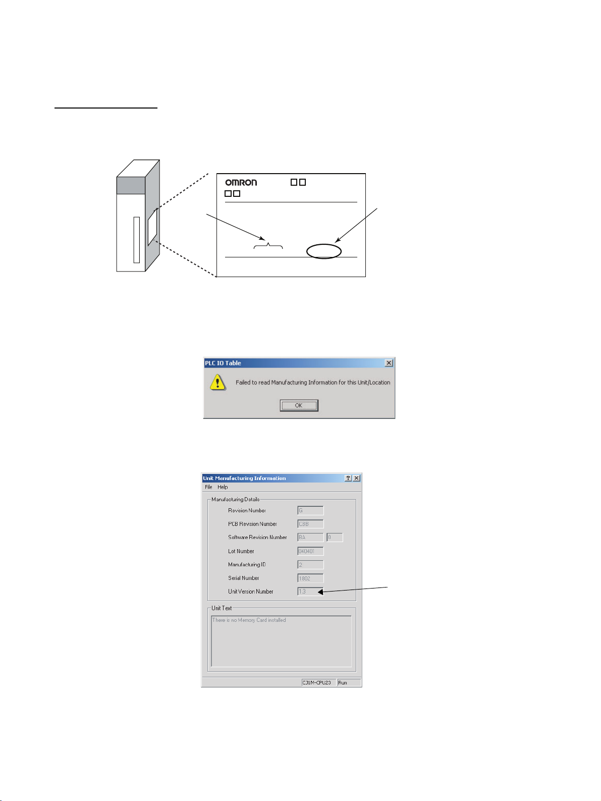
The unit version is given to the right of the lot number on the nameplate of the
products for which unit versions are being managed, as shown below.
Product nameplate
CS1W-
UNIT
Lot No.
Lot No. 040401 0000 Ver.1.3
OMRON Corporation MADE IN JAPAN
Unit version
Example for unit version 1.3
CX-Programmer version 4.0 can be used to confirm the unit version using the
Unit Manufacturing Information.
Note The (unit versions of) Pre-Ver. 2.0 Units cannot be confirmed Unit Manufac-
turing Information. The following dialog box is displayed.
In the IO Table Window, right-click and select Unit Manufacturing informa-
tion - CPU Unit.
The following Unit Manufacturing information Dialog Box will be displayed.
Unit version
Use the above display to confirm the unit version of the Unit connected online.
vi

Using Unit Version Label The following unit version label is provided with the Ethernet Unit.
This label can be attached to the front of the Ethernet Unit to differentiate
between Ethernet Units with different unit versions.
Unit Version Notation In this manual, the unit version of a Ethernet Unit is given as shown in the fol-
lowing table.
Product nameplate Notation used in this manual Special remarks
Ver. 2.0 or later number
shown to right of the lot
number
Blank to the right of lot
number
Ethernet Unit Ver. 1.3 or later Information without reference to specific Unit
Versions applies to all versions of the Unit
Pre-Ver. 1.3 Ethernet Units
vii

viii

TABLE OF CONTENTS
PRECAUTIONS . . . . . . . . . . . . . . . . . . . . . . . . . . . . . . . . . . . . . xxi
1 Intended Audience . . . . . . . . . . . . . . . . . . . . . . . . . . . . . . . . . . . . . . . . . . . . . . . . . . . . . . . . . . . xxii
2 General Precautions . . . . . . . . . . . . . . . . . . . . . . . . . . . . . . . . . . . . . . . . . . . . . . . . . . . . . . . . . . xxii
3 Safety Precautions. . . . . . . . . . . . . . . . . . . . . . . . . . . . . . . . . . . . . . . . . . . . . . . . . . . . . . . . . . . . xxii
4 Operating Environment Precautions . . . . . . . . . . . . . . . . . . . . . . . . . . . . . . . . . . . . . . . . . . . . . . xxiii
5 Application Precautions . . . . . . . . . . . . . . . . . . . . . . . . . . . . . . . . . . . . . . . . . . . . . . . . . . . . . . . xxiii
6 Conformance to EC Directives . . . . . . . . . . . . . . . . . . . . . . . . . . . . . . . . . . . . . . . . . . . . . . . . . . xxv
SECTION 1
Features and System Configuration . . . . . . . . . . . . . . . . . . . . . 1
1-1 Ethernet Unit Function Guide . . . . . . . . . . . . . . . . . . . . . . . . . . . . . . . . . . . . . . . . . . . . . . . . . . . 2
1-2 Features . . . . . . . . . . . . . . . . . . . . . . . . . . . . . . . . . . . . . . . . . . . . . . . . . . . . . . . . . . . . . . . . . . . . 8
1-3 System Configuration . . . . . . . . . . . . . . . . . . . . . . . . . . . . . . . . . . . . . . . . . . . . . . . . . . . . . . . . . 11
1-4 Specifications . . . . . . . . . . . . . . . . . . . . . . . . . . . . . . . . . . . . . . . . . . . . . . . . . . . . . . . . . . . . . . . 14
1-5 Overview of Communications Functions . . . . . . . . . . . . . . . . . . . . . . . . . . . . . . . . . . . . . . . . . . 17
1-6 Nomenclature and Functions . . . . . . . . . . . . . . . . . . . . . . . . . . . . . . . . . . . . . . . . . . . . . . . . . . . 23
1-7 Comparison with Previous Models . . . . . . . . . . . . . . . . . . . . . . . . . . . . . . . . . . . . . . . . . . . . . . . 27
1-8 Unit Version Upgrade Information . . . . . . . . . . . . . . . . . . . . . . . . . . . . . . . . . . . . . . . . . . . . . . . 28
SECTION 2
Installation and Initial Setup. . . . . . . . . . . . . . . . . . . . . . . . . . . 29
2-1 Overview of Startup Procedure. . . . . . . . . . . . . . . . . . . . . . . . . . . . . . . . . . . . . . . . . . . . . . . . . . 30
2-2 Switch Settings . . . . . . . . . . . . . . . . . . . . . . . . . . . . . . . . . . . . . . . . . . . . . . . . . . . . . . . . . . . . . . 31
2-3 Mounting to a PLC . . . . . . . . . . . . . . . . . . . . . . . . . . . . . . . . . . . . . . . . . . . . . . . . . . . . . . . . . . . 33
2-4 Network Installation . . . . . . . . . . . . . . . . . . . . . . . . . . . . . . . . . . . . . . . . . . . . . . . . . . . . . . . . . . 34
2-5 Connecting to the Network . . . . . . . . . . . . . . . . . . . . . . . . . . . . . . . . . . . . . . . . . . . . . . . . . . . . . 38
2-6 Creating I/O Tables . . . . . . . . . . . . . . . . . . . . . . . . . . . . . . . . . . . . . . . . . . . . . . . . . . . . . . . . . . . 39
2-7 Unit Setup Procedure . . . . . . . . . . . . . . . . . . . . . . . . . . . . . . . . . . . . . . . . . . . . . . . . . . . . . . . . . 41
2-8 Basic Settings . . . . . . . . . . . . . . . . . . . . . . . . . . . . . . . . . . . . . . . . . . . . . . . . . . . . . . . . . . . . . . . 46
2-9 Unit Setup for Particular Applications . . . . . . . . . . . . . . . . . . . . . . . . . . . . . . . . . . . . . . . . . . . . 50
2-10 Communications Test . . . . . . . . . . . . . . . . . . . . . . . . . . . . . . . . . . . . . . . . . . . . . . . . . . . . . . . . . 52
2-11 Converting from Previous Models . . . . . . . . . . . . . . . . . . . . . . . . . . . . . . . . . . . . . . . . . . . . . . . 54
SECTION 3
CX-Programmer Unit Setup . . . . . . . . . . . . . . . . . . . . . . . . . . . 61
3-1 Setup . . . . . . . . . . . . . . . . . . . . . . . . . . . . . . . . . . . . . . . . . . . . . . . . . . . . . . . . . . . . . . . . . . . . . . 62
3-2 FINS/TCP . . . . . . . . . . . . . . . . . . . . . . . . . . . . . . . . . . . . . . . . . . . . . . . . . . . . . . . . . . . . . . . . . . 64
3-3 DNS. . . . . . . . . . . . . . . . . . . . . . . . . . . . . . . . . . . . . . . . . . . . . . . . . . . . . . . . . . . . . . . . . . . . . . . 66
3-4 SMTP . . . . . . . . . . . . . . . . . . . . . . . . . . . . . . . . . . . . . . . . . . . . . . . . . . . . . . . . . . . . . . . . . . . . . 67
3-5 POP . . . . . . . . . . . . . . . . . . . . . . . . . . . . . . . . . . . . . . . . . . . . . . . . . . . . . . . . . . . . . . . . . . . . . . . 68
3-6 Mail Address . . . . . . . . . . . . . . . . . . . . . . . . . . . . . . . . . . . . . . . . . . . . . . . . . . . . . . . . . . . . . . . . 69
3-7 Send Mail . . . . . . . . . . . . . . . . . . . . . . . . . . . . . . . . . . . . . . . . . . . . . . . . . . . . . . . . . . . . . . . . . . 70
3-8 Receive Mail . . . . . . . . . . . . . . . . . . . . . . . . . . . . . . . . . . . . . . . . . . . . . . . . . . . . . . . . . . . . . . . . 72
ix

TABLE OF CONTENTS
3-9 Auto Adjust Time . . . . . . . . . . . . . . . . . . . . . . . . . . . . . . . . . . . . . . . . . . . . . . . . . . . . . . . . . . . . 74
3-10 HTTP. . . . . . . . . . . . . . . . . . . . . . . . . . . . . . . . . . . . . . . . . . . . . . . . . . . . . . . . . . . . . . . . . . . . . . 75
SECTION 4
Ethernet Unit Memory Allocations. . . . . . . . . . . . . . . . . . . . . . 77
4-1 CIO Area Allocations . . . . . . . . . . . . . . . . . . . . . . . . . . . . . . . . . . . . . . . . . . . . . . . . . . . . . . . . . 78
4-2 DM Area Allocations . . . . . . . . . . . . . . . . . . . . . . . . . . . . . . . . . . . . . . . . . . . . . . . . . . . . . . . . . 86
4-3 Auxiliary Area Data . . . . . . . . . . . . . . . . . . . . . . . . . . . . . . . . . . . . . . . . . . . . . . . . . . . . . . . . . . 90
SECTION 5
Determining IP Addresses . . . . . . . . . . . . . . . . . . . . . . . . . . . . . 93
5-1 IP Addresses . . . . . . . . . . . . . . . . . . . . . . . . . . . . . . . . . . . . . . . . . . . . . . . . . . . . . . . . . . . . . . . . 94
5-2 IP Addresses in FINS Communications . . . . . . . . . . . . . . . . . . . . . . . . . . . . . . . . . . . . . . . . . . . 96
5-3 Private and Global Addresses . . . . . . . . . . . . . . . . . . . . . . . . . . . . . . . . . . . . . . . . . . . . . . . . . . . 108
SECTION 6
FINS Communications . . . . . . . . . . . . . . . . . . . . . . . . . . . . . . . . 115
6-1 Overview of FINS Communications. . . . . . . . . . . . . . . . . . . . . . . . . . . . . . . . . . . . . . . . . . . . . . 116
6-2 FINS/UDP Method . . . . . . . . . . . . . . . . . . . . . . . . . . . . . . . . . . . . . . . . . . . . . . . . . . . . . . . . . . . 118
6-3 FINS/TCP Method . . . . . . . . . . . . . . . . . . . . . . . . . . . . . . . . . . . . . . . . . . . . . . . . . . . . . . . . . . . 120
6-4 Creating Routing Tables . . . . . . . . . . . . . . . . . . . . . . . . . . . . . . . . . . . . . . . . . . . . . . . . . . . . . . . 124
6-5 Using FINS Applications . . . . . . . . . . . . . . . . . . . . . . . . . . . . . . . . . . . . . . . . . . . . . . . . . . . . . . 128
6-6 Communicating between OMRON PLCs. . . . . . . . . . . . . . . . . . . . . . . . . . . . . . . . . . . . . . . . . . 137
6-7 Precautions on High Traffic in FINS Communications . . . . . . . . . . . . . . . . . . . . . . . . . . . . . . . 155
SECTION 7
FINS Commands Addressed to Ethernet Units. . . . . . . . . . . . 157
7-1 Command Codes and Response Codes. . . . . . . . . . . . . . . . . . . . . . . . . . . . . . . . . . . . . . . . . . . . 158
7-2 Socket Applications . . . . . . . . . . . . . . . . . . . . . . . . . . . . . . . . . . . . . . . . . . . . . . . . . . . . . . . . . . 159
7-3 Command/Response Reference . . . . . . . . . . . . . . . . . . . . . . . . . . . . . . . . . . . . . . . . . . . . . . . . . 161
SECTION 8
Troubleshooting . . . . . . . . . . . . . . . . . . . . . . . . . . . . . . . . . . . . . 203
8-1 Troubleshooting with Indicators . . . . . . . . . . . . . . . . . . . . . . . . . . . . . . . . . . . . . . . . . . . . . . . . . 204
8-2 Error Status . . . . . . . . . . . . . . . . . . . . . . . . . . . . . . . . . . . . . . . . . . . . . . . . . . . . . . . . . . . . . . . . . 205
8-3 Error Log. . . . . . . . . . . . . . . . . . . . . . . . . . . . . . . . . . . . . . . . . . . . . . . . . . . . . . . . . . . . . . . . . . . 206
8-4 Troubleshooting Procedures . . . . . . . . . . . . . . . . . . . . . . . . . . . . . . . . . . . . . . . . . . . . . . . . . . . . 213
8-5 Results Storage Area Response Codes . . . . . . . . . . . . . . . . . . . . . . . . . . . . . . . . . . . . . . . . . . . . 231
x

TABLE OF CONTENTS
Appendices
A Ethernet Network Parameters . . . . . . . . . . . . . . . . . . . . . . . . . . . . . . . . . . . . . . . . . . . . . . . . . . 235
B Buffer Configuration . . . . . . . . . . . . . . . . . . . . . . . . . . . . . . . . . . . . . . . . . . . . . . . . . . . . . . . . . 237
C TCP Status Transitions . . . . . . . . . . . . . . . . . . . . . . . . . . . . . . . . . . . . . . . . . . . . . . . . . . . . . . . . 239
D ASCII Characters . . . . . . . . . . . . . . . . . . . . . . . . . . . . . . . . . . . . . . . . . . . . . . . . . . . . . . . . . . . . 241
E Maintenance . . . . . . . . . . . . . . . . . . . . . . . . . . . . . . . . . . . . . . . . . . . . . . . . . . . . . . . . . . . . . . . . 243
F Inspections . . . . . . . . . . . . . . . . . . . . . . . . . . . . . . . . . . . . . . . . . . . . . . . . . . . . . . . . . . . . . . . . . 245
G Ethernet Unit Web Function . . . . . . . . . . . . . . . . . . . . . . . . . . . . . . . . . . . . . . . . . . . . . . . . . . . . 247
Index . . . . . . . . . . . . . . . . . . . . . . . . . . . . . . . . . . . . . . . . . . . . . . 253
Revision History . . . . . . . . . . . . . . . . . . . . . . . . . . . . . . . . . . . . . 261
xi

xii

About this Manual:
This manual describes the installation and operation of the CS1W-ETN21 and CJ1W-ETN21 Ethernet
Units (100Base-TX) and includes the sections described below.
Please read this manual carefully and be sure you understand the information provided before
attempting to install or operate the Ethernet Unit. Be sure to read the precautions provided in the following section.
Precautions provides general precautions for using the CS1W-ETN21 and CJ1W-ETN21 Ethernet
Units (100Base-TX).
Section 1 introduces the features, describes the system configuration and Unit parts, and provides
Unit specifications.
Section 2 explains how to install the Ethernet Unit and make the initial settings required for operation.
Section 3 provides information for setting communications using CX-Programmer.
Section 4 describes the words allocated in the CIO Area and the DM Area for Ethernet Units.
Section 5 explains how to manage and use IP addresses.
Section 6 provides information on communicating on Ethernet Systems and interconnected networks
using FINS commands.
Section 7 describes the FINS commands that can be sent to an Ethernet Unit and the responses that
are returned by the Ethernet Unit.
Section 8 describes information and procedures that can be used to troubleshoot problems that sometimes occur with Ethernet Unit and Ethernet communications.
Appendices provide information on Ethernet network parameters, the buffer configuration, TCP status
transitions, ASCII characters, maintenance, and inspections.
The related Ethernet Units Operation Manual Construction of Applications (W421) provides the following information.
Section Contents
Section 1 Overview of functions for constructing applications.
Section 2 Information on using mail functions to automatically send I/O memory data from
OMRON PLCs to personal computers.
Section 3 Information on using mail functions to send commands from OMRON PLCs to per-
sonal computers.
Section 4 Information on transferring large files between personal computers and OMRON
Section 5 Information on automatically adjusting the OMRON PLC’s built-in clock.
Section 6 Information on communicating between general applications (applications not using
Section 7 Information on using personal computer and UNIX machine socket interfaces to cre-
PLCs.
FINS) and OMRON PLCs.
ate applications using FINS communications.
xiii

Relevant Manuals
The following table lists CS and CJ-series manuals that contain information relevant to Ethernet Units.
Manual
number
W420
W421 CS1W-ETN21
W343
W342
W339
W393
W394 CS1G/H-CPU@@H
W340
CS1W-ETN21
CJ1W-ETN21
CJ1W-ETN21
CS1W-ETN01
CS1W-ETN11
CJ1W-ETN11
CS1G/H-CPU@@H
CS1G/H-CPU-@@EV1
CS1D-CPU@@H
CS1D-CPU@@S
CJ1M-CPU@@
CS1W-SCU21-V1
CS1W-SCB21-V1/41-V1
CJ1G/H-CPU@@H
CJ1G-CPU@@P
CJ1G-CPU@@
CJ1W-SCU21-V1/41-V1
CS1G/H-CPU@@H
CS1G/H-CPU@@-EV1
CJ1G/H-CPU@@H
CJ1G-CPU@@P
CJ1M-CPU@@
CJ1G-CPU@@
CS1G/H-CPU@@EV1
CS1D-CPU@@H
CS1D-CPU@@S
CJ1G/H-CPU@@H
CJ1G-CPU@@P
CJ1G-CPU@@
CJ1M-CPU@@
CS1G/H-CPU@@H
CS1G/H-CPU@@EV1
CS1D-CPU@@H
CS1D-CPU@@S
CJ1G/H-CPU@@H
CJ1G-CPU@@P
CJ1G-CPU@@
CJ1M-CPU@@
Model Name Contents
Ethernet Units Operation Manual
Construction of Networks
(this manual)
Ethernet Units Operation Manual
Construction of
Applications
Ethernet Units Operation Manual
Communications
Commands Reference Manual
Programmable Controllers Operation
Manual
Programmable Controllers Operation
Manual
Programmable Controllers Programming Manual
Programmable Controllers Instructions
Reference Manual
Provides information on operating and installing
100Base-TX Ethernet Units, including details on basic
settings and FINS communications.
Refer to the Communications Commands Reference
Manual (W342) for details on FINS commands that can
be sent to CS-series and CJ-series CPU Units when
using the FINS communications service.
Provides information on constructing host applications for
100Base-TX Ethernet Units, including functions for sending/receiving mail, socket service, automatic clock adjustment, FTP server functions, and FINS communications.
Describes the installation and operation of the 10Base-5
and 10Base-T Ethernet Units.
Describes the C-series (Host Link) and FINS communications commands used when sending communications
commands to CS-series and CJ-series CPU Units.
Provides an outline of, and describes the design, installation, maintenance, and other basic operations for the CSseries PLCs. Information is also included on features,
system configuration, wiring, I/O memory allocations, and
troubleshooting.
Use together with the Programmable Controllers Pro-
gramming Manual (W394).
Provides an outline of, and describes the design, installation, maintenance, and other basic operations for the CJseries PLCs. Information is also included on features,
system configuration, wiring, I/O memory allocations, and
troubleshooting.
Use together with the Programmable Controllers Pro-
gramming Manual (W394).
Describes programming, tasks, file memory, and other
functions for the CS-series and CJ-series PLCs.
Use together with the Programmable Controllers Opera-
tion Manual (W339 for CS-series PLCs and W393 for CJseries PLCs).
Describes the ladder diagram programming instructions
supported by CS-series and CJ-series PCs. Use together
with the Programmable Controllers Operation Manual
(W339 for CS-series PLCs and W393 for CJ-series
PLCs), and Programmable Controllers Programming
Manual (W394).
xiv

Manual
number
W446 WS02-CXPC@-V8 CX-Programmer
W444 CXONE-AL@@C-E CX-One Setup Man-
W445 CXONE-AL@@C-E CX-Integrator Opera-
W341
W336
CQM1H-PRO01-E
CQM1-PRO01-E
C200H-PRO27-E
CS1W-SCB21-V1/41-V1
CS1W-SCU21-V1
CJ1W-SCU21-V1/41-V1
Model Name Contents
Ver. 8.0 Operation
Manual
ual
tion Manual
Programming Consoles Operation
Manual
Serial Communications Boards and
Serial Communications Units Operation
Manual
Provides information on how to use the CX-Programmer,
a Windows-based programming device, and CX-Net, a
Windows-based network configuration tool.
Use together with the Programmable Controllers Opera-
tion Manual (W339 for CS-series PLCs and W393 for CJseries PLCs), Programmable Controllers Programming
Manual (W394) and the Programmable Controllers
Instructions Reference Manual (W340) to perform pro-
gramming.
Describes operating procedures for the CX-One FA Inte-
grated Tool Package.
Refer to this manual for operating procedures for the CX-
One FA Integrated Tool Package.
Describes operating procedures for the CX-Integrator net-
work configuration support software for CS/CJ-series
PLCs.
Refer to this manual for operating procedures for the CXIntegrator network configuration support software for CS/
CJ-series PLCs.
Provides information on how to operate the Programming
Console.
Use together with the Programmable Controllers Opera-
tion Manual (W339 for CS-series PLCs and W393 for CJseries PLCs), Programmable Controllers Programming
Manual (W394) and the Programmable Controllers
Instructions Reference Manual (W340) to perform pro-
gramming.
Accessing the PLC connected to the CX-Programmer via
Ethernet or the host computer or other device connected
to the Serial Communications Board or Unit.
Describes the use of Serial Communications Units and
Boards, including details on hardware, software, and
standard system protocols.
!WARNING Failure to read and understand the information provided in this manual may result in per-
sonal injury or death, damage to the product, or product failure. Please read each section
in its entirety and be sure you understand the information provided in the section and
related sections before attempting any of the procedures or operations given.
xv

xvi

Read and Understand this Manual
Please read and understand this manual before using the product. Please consult your OMRON
representative if you have any questions or comments.
Warranty and Limitations of Liability
WARRANTY
OMRON's exclusive warranty is that the products are free from defects in materials and workmanship for a
period of one year (or other period if specified) from date of sale by OMRON.
OMRON MAKES NO WARRANTY OR REPRESENTATION, EXPRESS OR IMPLIED, REGARDING NONINFRINGEMENT, MERCHANTABILITY, OR FITNESS FOR PARTICULAR PURPOSE OF THE
PRODUCTS. ANY BUYER OR USER ACKNOWLEDGES THAT THE BUYER OR USER ALONE HAS
DETERMINED THAT THE PRODUCTS WILL SUITABLY MEET THE REQUIREMENTS OF THEIR
INTENDED USE. OMRON DISCLAIMS ALL OTHER WARRANTIES, EXPRESS OR IMPLIED.
LIMITATIONS OF LIABILITY
OMRON SHALL NOT BE RESPONSIBLE FOR SPECIAL, INDIRECT, OR CONSEQUENTIAL DAMAGES,
LOSS OF PROFITS OR COMMERCIAL LOSS IN ANY WAY CONNECTED WITH THE PRODUCTS,
WHETHER SUCH CLAIM IS BASED ON CONTRACT, WARRANTY, NEGLIGENCE, OR STRICT
LIABILITY.
In no event shall the responsibility of OMRON for any act exceed the individual price of the product on which
liability is asserted.
IN NO EVENT SHALL OMRON BE RESPONSIBLE FOR WARRANTY, REPAIR, OR OTHER CLAIMS
REGARDING THE PRODUCTS UNLESS OMRON'S ANALYSIS CONFIRMS THAT THE PRODUCTS
WERE PROPERLY HANDLED, STORED, INSTALLED, AND MAINTAINED AND NOT SUBJECT TO
CONTAMINATION, ABUSE, MISUSE, OR INAPPROPRIATE MODIFICATION OR REPAIR.
xvii

Application Considerations
SUITABILITY FOR USE
OMRON shall not be responsible for conformity with any standards, codes, or regulations that apply to the
combination of products in the customer's application or use of the products.
At the customer's request, OMRON will provide applicable third party certification documents identifying
ratings and limitations of use that apply to the products. This information by itself is not sufficient for a
complete determination of the suitability of the products in combination with the end product, machine,
system, or other application or use.
The following are some examples of applications for which particular attention must be given. This is not
intended to be an exhaustive list of all possible uses of the products, nor is it intended to imply that the uses
listed may be suitable for the products:
• Outdoor use, uses involving potential chemical contamination or electrical interference, or conditions or
uses not described in this manual.
• Nuclear energy control systems, combustion systems, railroad systems, aviation systems, medical
equipment, amusement machines, vehicles, safety equipment, and installations subject to separate
industry or government regulations.
• Systems, machines, and equipment that could present a risk to life or property.
Please know and observe all prohibitions of use applicable to the products.
NEVER USE THE PRODUCTS FOR AN APPLICATION INVOLVING SERIOUS RISK TO LIFE OR
PROPERTY WITHOUT ENSURING THAT THE SYSTEM AS A WHOLE HAS BEEN DESIGNED TO
ADDRESS THE RISKS, AND THAT THE OMRON PRODUCTS ARE PROPERLY RATED AND
INSTALLED FOR THE INTENDED USE WITHIN THE OVERALL EQUIPMENT OR SYSTEM.
PROGRAMMABLE PRODUCTS
OMRON shall not be responsible for the user's programming of a programmable product, or any
consequence thereof.
xviii

Disclaimers
CHANGE IN SPECIFICATIONS
Product specifications and accessories may be changed at any time based on improvements and other
reasons.
It is our practice to change model numbers when published ratings or features are changed, or when
significant construction changes are made. However, some specifications of the products may be changed
without any notice. When in doubt, special model numbers may be assigned to fix or establish key
specifications for your application on your request. Please consult with your OMRON representative at any
time to confirm actual specifications of purchased products.
DIMENSIONS AND WEIGHTS
Dimensions and weights are nominal and are not to be used for manufacturing purposes, even when
tolerances are shown.
PERFORMANCE DATA
Performance data given in this manual is provided as a guide for the user in determining suitability and does
not constitute a warranty. It may represent the result of OMRON's test conditions, and the users must
correlate it to actual application requirements. Actual performance is subject to the OMRON Warranty and
Limitations of Liability.
ERRORS AND OMISSIONS
The information in this manual has been carefully checked and is believed to be accurate; however, no
responsibility is assumed for clerical, typographical, or proofreading errors, or omissions.
xix

xx

PRECAUTIONS
This section provides general precautions for using the CS1W-ETN21 and CJ1W-ETN21 Ethernet Units (100Base-TX).
The information contained in this section is important for the safe and reliable application of Ethernet Units. You
must read this section and understand the information contained before attempting to set up or operate an Ethernet
Unit.
1 Intended Audience . . . . . . . . . . . . . . . . . . . . . . . . . . . . . . . . . . . . . . . . . . . . . xxii
2 General Precautions . . . . . . . . . . . . . . . . . . . . . . . . . . . . . . . . . . . . . . . . . . . . xxii
3 Safety Precautions. . . . . . . . . . . . . . . . . . . . . . . . . . . . . . . . . . . . . . . . . . . . . . xxii
4 Operating Environment Precautions . . . . . . . . . . . . . . . . . . . . . . . . . . . . . . . . xxiii
5 Application Precautions . . . . . . . . . . . . . . . . . . . . . . . . . . . . . . . . . . . . . . . . . xxiii
6 Conformance to EC Directives . . . . . . . . . . . . . . . . . . . . . . . . . . . . . . . . . . . . xxv
6-1 Applicable Directives . . . . . . . . . . . . . . . . . . . . . . . . . . . . . . . . . . . . xxv
6-2 Concepts . . . . . . . . . . . . . . . . . . . . . . . . . . . . . . . . . . . . . . . . . . . . . . xxv
xxi

Intended Audience 1
1 Intended Audience
This manual is intended for the following personnel, who must also have
knowledge of electrical systems (an electrical engineer or the equivalent).
• Personnel in charge of installing FA systems.
• Personnel in charge of designing FA systems.
• Personnel in charge of managing FA systems and facilities.
2 General Precautions
The user must operate the product according to the performance specifications described in the operation manuals.
Before using the product under conditions which are not described in the
manual or applying the product to nuclear control systems, railroad systems,
aviation systems, vehicles, combustion systems, medical equipment, amusement machines, safety equipment, and other systems, machines, and equipment that may have a serious influence on lives and property if used
improperly, consult your OMRON representative.
Make sure that the ratings and performance characteristics of the product are
sufficient for the systems, machines, and equipment, and be sure to provide
the systems, machines, and equipment with double safety mechanisms.
This manual provides information for programming and operating the Unit. Be
sure to read this manual before attempting to use the Unit and keep this manual close at hand for reference during operation.
!WARNING It is extremely important that a PLC and all PLC Units be used for the speci-
fied purpose and under the specified conditions, especially in applications that
can directly or indirectly affect human life. You must consult with your OMRON
representative before applying a PLC System to the above-mentioned applications.
3 Safety Precautions
!WARNING Do not attempt to take any Unit apart while the power is being supplied. Doing
so may result in electric shock.
!WARNING Do not touch any of the terminals or terminal blocks while the power is being
supplied. Doing so may result in electric shock.
!WARNING Do not attempt to disassemble, repair, or modify any Units. Any attempt to do
so may result in malfunction, fire, or electric shock.
!Caution Execute online editing only after confirming that no adverse effects will be
caused by extending the cycle time. Otherwise, the input signals may not be
readable.
xxii

Operating Environment Precautions 4
• Emergency stop circuits, interlock circuits, limit circuits, and similar safety
measures must be provided in external control circuits.
!Caution Tighten the screws on the terminal block of the AC Power Supply Unit to the
torque specified in the operation manual. The loose screws may result in
burning or malfunction.
4 Operating Environment Precautions
!Caution Do not operate the control system in the following locations:
• Locations subject to direct sunlight.
• Locations subject to temperatures or humidity outside the range specified
in the specifications.
• Locations subject to condensation as the result of severe changes in temperature.
• Locations subject to corrosive or flammable gases.
• Locations subject to dust (especially iron dust) or salts.
• Locations subject to exposure to water, oil, or chemicals.
• Locations subject to shock or vibration.
!Caution Take appropriate and sufficient countermeasures when installing systems in
the following locations:
• Locations subject to static electricity or other forms of noise.
• Locations subject to strong electromagnetic fields.
• Locations subject to possible exposure to radioactivity.
• Locations close to power supplies.
5 Application Precautions
Observe the following precautions when using the Ethernet Unit.
!WARNING Always heed these precautions. Failure to abide by the following precautions
could lead to serious or possibly fatal injury.
• Always connect to a ground of 100
connecting to a ground of 100
Ω or less when installing the Units. Not
Ω or less may result in electric shock.
xxiii

Application Precautions 5
• Always turn OFF the power supply to the CPU Unit, Slaves, and Communications Units before attempting any of the following. Not turning OFF
the power supply may result in malfunction or electric shock.
• Mounting or dismounting I/O Units, CPU Units, Memory Packs, or
Master Units.
• Assembling the Units.
• Setting DIP switches or rotary switches.
• Connecting cables or wiring the system.
!Caution Failure to abide by the following precautions could lead to faulty operation of
the Ethernet Unit or the system, or could damage the Ethernet Unit. Always
heed these precautions.
• Fail-safe measures must be taken by the customer to ensure safety in the
event of incorrect, missing, or abnormal signals caused by broken signal
lines, momentary power interruptions, or other causes.
• Interlock circuits, limit circuits, and similar safety measures in external circuits (i.e., not in the Programmable Controller) must be provided by the
customer.
• Always use the power supply voltages specified in the operation manuals.
An incorrect voltage may result in malfunction or burning.
• Take appropriate measures to ensure that the specified power with the
rated voltage and frequency is supplied. Be particularly careful in places
where the power supply is unstable. An incorrect power supply may result
in malfunction.
• Install external breakers and take other safety measures against short-circuiting in external wiring. Insufficient safety measures against short-circuiting may result in burning.
• Do not install the Unit near devices that generate strong high-frequency
noise.
• Do not drop the Unit or subject it to excessive vibration or shock.
• Make sure that all the Backplane mounting screws, terminal block screws,
and cable connector screws are tightened to the torque specified in the
relevant manuals. Incorrect tightening torque may result in malfunction.
• Leave the label attached to the Unit when wiring. Removing the label may
result in malfunction if foreign matter enters the Unit.
• Remove the label after the completion of wiring to ensure proper heat dissipation. Leaving the label attached may result in malfunction.
• Use crimp terminals for wiring. Do not connect bare stranded wires
directly to terminals. Connection of bare stranded wires may result in
burning.
• Double-check all wiring and switch settings before turning ON the power
supply. Incorrect wiring may result in burning.
• Wire all connections correctly.
• Mount Units only after checking terminal blocks and connectors completely.
• Make sure that the terminal blocks, expansion cables, and other items
with locking devices are locked in place.
• When transporting the Unit, use special packing boxes and protect it from
being exposed to excessive vibration or impacts during transportation.
xxiv

Conformance to EC Directives 6
• Check the user program for proper execution before actually running it on
the Unit. Not checking the program may result in unexpected operation.
• Observe the following precautions when wiring the communications
cable.
• Separate the communications cables from the power lines or high-tension lines.
• Do not bend the communications cables past their natural bending radius.
• Do not pull on the communications cables.
• Do not place heavy objects on top of the communications cables.
• Always lay communications cable inside ducts.
• Use appropriate communications cables.
• Before touching a Unit, be sure to first touch a grounded metallic object in
order to discharge any static build-up. Not doing so may result in malfunction or damage.
• Confirm that no adverse effect will occur in the system before attempting
any of the following. Not doing so may result in an unexpected operation.
• Changing the operating mode of the PLC (including the setting of the
startup operation mode).
• Force-setting/force-resetting any bit in memory.
• Changing the present value of any word or any set value in memory.
6 Conformance to EC Directives
6-1 Applicable Directives
•EMC Directives
• Low Voltage Directive
6-2 Concepts
EMC Directives
OMRON devices that comply with EC Directives also conform to the related
EMC standards so that they can be more easily built into other devices or the
overall machine. The actual products have been checked for conformity to
EMC standards (see the following note). Whether the products conform to the
standards in the system used by the customer, however, must be checked by
the customer.
EMC-related performance of the OMRON devices that comply with EC Directives will vary depending on the configuration, wiring, and other conditions of
the equipment or control panel on which the OMRON devices are installed.
The customer must, therefore, perform the final check to confirm that devices
and the overall machine conform to EMC standards.
Note Applicable EMS (Electromagnetic Susceptibility) and EMI (Electromagnetic
Interference) Standards in the EMC (Electromagnetic Compatibility) standards are as follows:
Unit/Board EMS EMI
CS1W-ETN21
CJ1W-ETN21
EN61000-6-2
EN61000-6-4
(Radiated emission: 10-m
regulations)
xxv

Conformance to EC Directives 6
Low Voltage Directive
Always ensure that devices operating at voltages of 50 to 1,000 V AC and 75
to 1,500 V DC meet the required safety standards for the PLC (EN61131-2).
xxvi

SECTION 1
Features and System Configuration
This section introduces the features, describes the system configuration and Unit parts, and provides Unit specifications.
1-1 Ethernet Unit Function Guide . . . . . . . . . . . . . . . . . . . . . . . . . . . . . . . . . . . . . 2
1-1-1 Overall System Configuration Example . . . . . . . . . . . . . . . . . . . . . . 2
1-1-2 Determining the Objectives . . . . . . . . . . . . . . . . . . . . . . . . . . . . . . . 2
1-2 Features . . . . . . . . . . . . . . . . . . . . . . . . . . . . . . . . . . . . . . . . . . . . . . . . . . . . . . 8
1-3 System Configuration . . . . . . . . . . . . . . . . . . . . . . . . . . . . . . . . . . . . . . . . . . . 11
1-3-1 System Configuration . . . . . . . . . . . . . . . . . . . . . . . . . . . . . . . . . . . . 11
1-3-2 Devices Required for Constructing a Network . . . . . . . . . . . . . . . . . 11
1-3-3 Setup Area and Related Peripheral Devices . . . . . . . . . . . . . . . . . . . 12
1-4 Specifications . . . . . . . . . . . . . . . . . . . . . . . . . . . . . . . . . . . . . . . . . . . . . . . . . 14
1-4-1 General Specifications . . . . . . . . . . . . . . . . . . . . . . . . . . . . . . . . . . . 14
1-4-2 Dimensions . . . . . . . . . . . . . . . . . . . . . . . . . . . . . . . . . . . . . . . . . . . . 15
1-4-3 Software Configuration. . . . . . . . . . . . . . . . . . . . . . . . . . . . . . . . . . . 16
1-5 Overview of Communications Functions . . . . . . . . . . . . . . . . . . . . . . . . . . . . 17
1-5-1 FINS Communications Service . . . . . . . . . . . . . . . . . . . . . . . . . . . . 17
1-5-2 Socket Services. . . . . . . . . . . . . . . . . . . . . . . . . . . . . . . . . . . . . . . . . 18
1-5-3 FTP Server Function. . . . . . . . . . . . . . . . . . . . . . . . . . . . . . . . . . . . . 20
1-5-4 Mail Send Function. . . . . . . . . . . . . . . . . . . . . . . . . . . . . . . . . . . . . . 20
1-5-5 Mail Receive Function . . . . . . . . . . . . . . . . . . . . . . . . . . . . . . . . . . . 21
1-5-6 Automatic Clock Adjustment Function . . . . . . . . . . . . . . . . . . . . . . 22
1-5-7 Specifying Servers by Host Name . . . . . . . . . . . . . . . . . . . . . . . . . . 22
1-6 Nomenclature and Functions . . . . . . . . . . . . . . . . . . . . . . . . . . . . . . . . . . . . . 23
1-6-1 Component Names . . . . . . . . . . . . . . . . . . . . . . . . . . . . . . . . . . . . . . 23
1-6-2 Indicators . . . . . . . . . . . . . . . . . . . . . . . . . . . . . . . . . . . . . . . . . . . . . 25
1-7 Comparison with Previous Models . . . . . . . . . . . . . . . . . . . . . . . . . . . . . . . . . 27
1-8 Unit Version Upgrade Information . . . . . . . . . . . . . . . . . . . . . . . . . . . . . . . . . 28
1
Ethernet Unit Function Guide Section 1-1
1-1 Ethernet Unit Function Guide
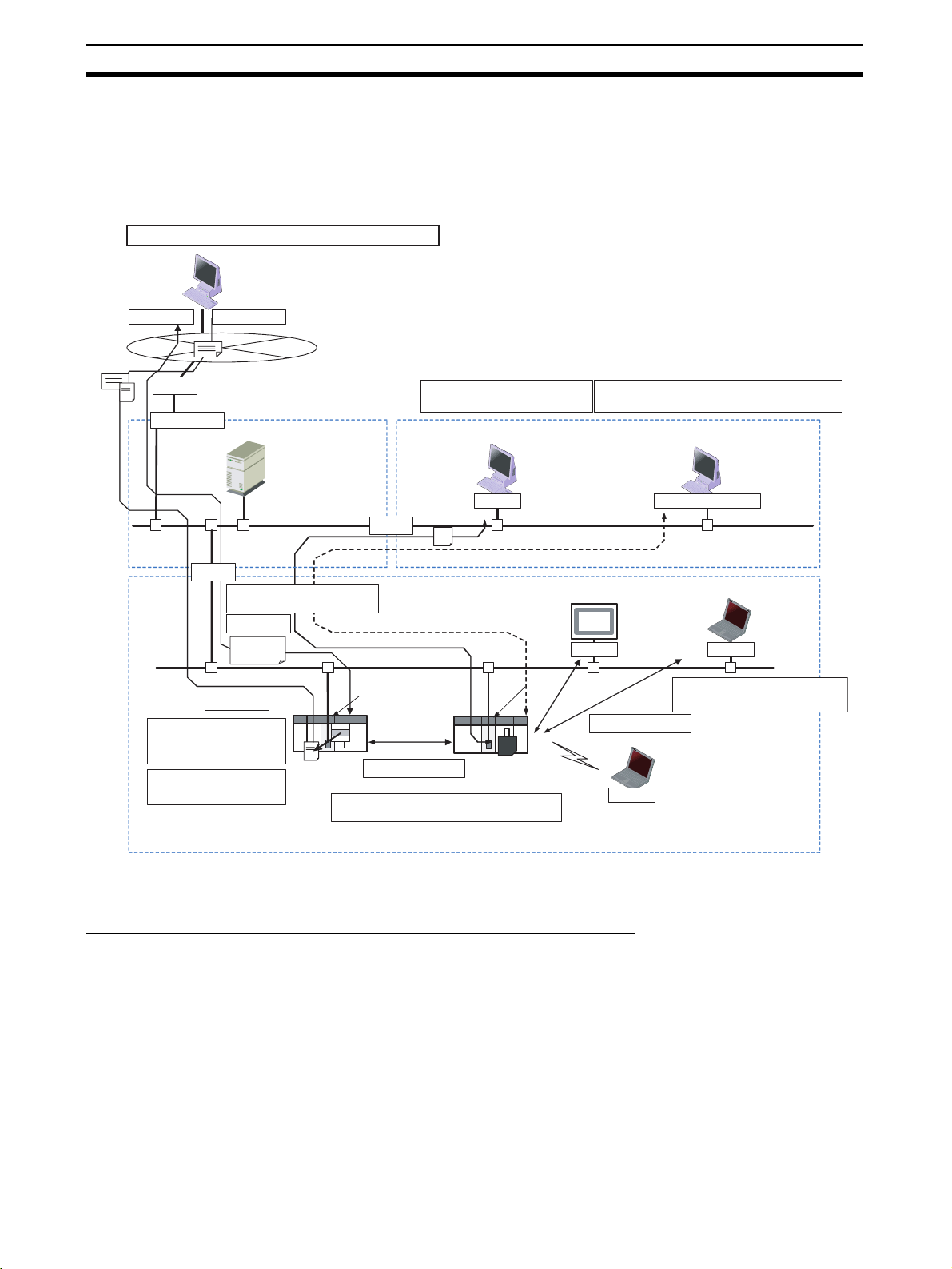
1-1-1 Overall System Configuration Example
The following diagram shows an example of an overall system configuration
using Ethernet Units.
(1) Connecting the CX-Programmer to the PLCs online via Ethernet
CX-Programmer
Mail software
Mail FINS
Mail
IP router
Firewall
(3) Capturing PLC changes
and sending the status of
equipment to an operator
(7) Automatically adjusting the
PLC's internal clock
periodically
Internet
Server Room
Router
(4) Receiving mail (data, files) at
PLCs
Receiving mail
Writing
commands
Sending mail
DNS server
POP3 server
SMTP server
SNTP server
Ethernet
(5) Transferring large data files between
Intranet
Router
Ethernet Unit Ethernet Unit
PLC PLC
FINS message
communications
(2) Sending and receiving data via Ethernet
between OMRON PLCs
personal computers and PLCs
FTP software
Mail software
Large files
(Factory line)
Ethernet
FTP
Memory Card
(6) Configuring an independent communications protocol
for the host application using TCP/IP (UDP/IP)
Office Floor
CX-Programmer
SCADA software
PLC Reporter, Compolet
FinsGateway
(communications driver)
Ethernet
FINS
FINS message
communications
Wireless
FINS
NS-series PT
Independent user
application
UDP/TCP socket
(1) Connecting the CX-Programmer to
PLCs online via Ethernet
CX-Programmer
FINS
1-1-2 Determining the Objectives
Connecting the CX-Programmer to PLCs Online via Ethernet
Connecting within the
Same Segment
2
Use the UDP/IP version of the FINS communications service (i.e., FINS/
UDP). FINS/UDP is supported by many OMRON products and is compatible
with earlier Ethernet Units (CS1W-ETN01/ETN11 and CJ1W-ETN11). The
CX-Programmer can be connected and used with FINS/UDP even if personal
computer middleware (FinsGateway) is not used. FinsGateway (any version)
can also be used together with the CX-Programmer.

Ethernet Unit Function Guide Section 1-1
Connecting through
Multiple Segments
Using Media with
Unreliable Connections,
Such as a Wireless LAN
Connecting from a
Personal Computer with a
Dynamic Private IP
Address
Use the TCP/IP version of the FINS communications service (i.e., FINS/TCP).
FINS/TCP is a new function supported by these Ethernet Units (CS1WETN21 and CJ1W-ETN21). It provides automatic recovery at the TCP/IP layer
from communications errors (such as packet loss) that occur during multilevel
routing. For CX-Programmer (version 4.0 or higher), FINS/TCP can be used
to directly connect to the PLC online. To use lower versions of the CX-Programmer with FINS/TCP, use FinsGateway (version 2003 or higher) as personal computer middleware.
Use the TCP/IP version of the FINS communications service (i.e., FINS/TCP).
FINS/TCP is a new function supported by these Ethernet Units (CS1WETN21 and CJ1W-ETN21). It provides automatic recovery at the TCP/IP layer
from communications errors (such as packet loss) resulting from unreliable
connections. For CX-Programmer (version 4.0 or higher), FINS/TCP can be
used to directly connect to the PLC online. To use lower versions of the CXProgrammer with FINS/TCP, use FinsGateway (version 2003 or higher) as
personal computer middleware.
Depending on whether or not the connection will be within the same segment,
either use an IP address conversion method for dynamic IP addresses in the
UDP/IP version of the FINS communications service or use the TCP/IP version of the FINS communications service.
It is possible to connect online to a PLC using the CX-Programmer from a
computer serving as a temporarily connected node or a permanent DHCP client.
For CX-Programmer (version 4.0 or higher), FINS/TCP can be used to directly
connect to the PLC online. To use lower versions of the CX-Programmer with
FINS/TCP, use FinsGateway (version 2003 or higher) as personal computer
middleware.
3
Ethernet Unit Function Guide Section 1-1
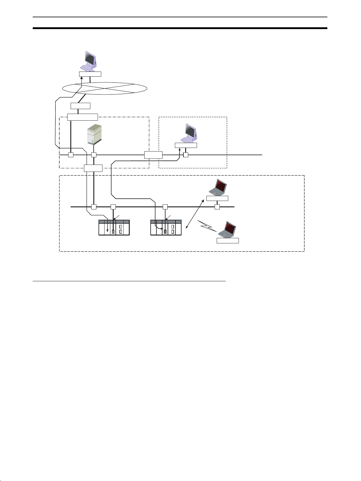
Connecting through multiple segments, such as over the Internet:
Use FINS/TCP.
CX-Programmer
FINS
Internet
IP router
Firewall
Router
(Server room)
DNS server
POP3 server
SMTP server
SNTP server
Intranet
Router
Connecting from a computer with a dynamic private IP address:
Use FINS/TCP or FINS/UDP.
(Office floor)
CX-Programmer
FINS
EthernetEthernet
(Production line)
Ethernet
Ethernet Unit Ethernet Unit
CX-Programmer
PLC
FINS
Wireless
Reference SECTION 6 FINS Communications
Exchanging Data between OMRON PLCs using Ethernet
Connecting within the
Same Segment
Use the UDP/IP version of the FINS communications service (i.e., FINS/
UDP), and construct applications using the SEND(090), RECV(098), and
CMND(490) instructions in the ladder program. FINS/UDP is supported by
many OMRON products, and is compatible with earlier Ethernet Units (CS1WETN01/ETN11 and CJ1W-ETN11). The protocol processing for FINS/UDP is
simpler than for FINS/TCP, giving FINS/UDP certain advantages in terms of
performance. Another feature of FINS/UDP is that it can be used for broadcasting.
On the other hand, with FINS/UDP it is necessary to provide measures, such
as retries, for handling communications errors.
Connecting within the same segment:
Use FINS/UDP.
CX-Programmer
Using media with unreliable
connections, such as wireless
FINS
LAN: Use FINS/TCP.
Connecting through
Multiple Segments
4
Use the TCP/IP version of the FINS communications service (i.e., FINS/TCP),
and construct applications using the SEND(090), RECV(098), and
CMND(490) instructions in the ladder program. FINS/TCP is the initial function supported by this Ethernet Unit (CS1W-ETN21 and CJ1W-ETN21). It provides automatic recovery at the TCP/IP layer from communications errors
(such as packet loss) that occur during multilevel routing.
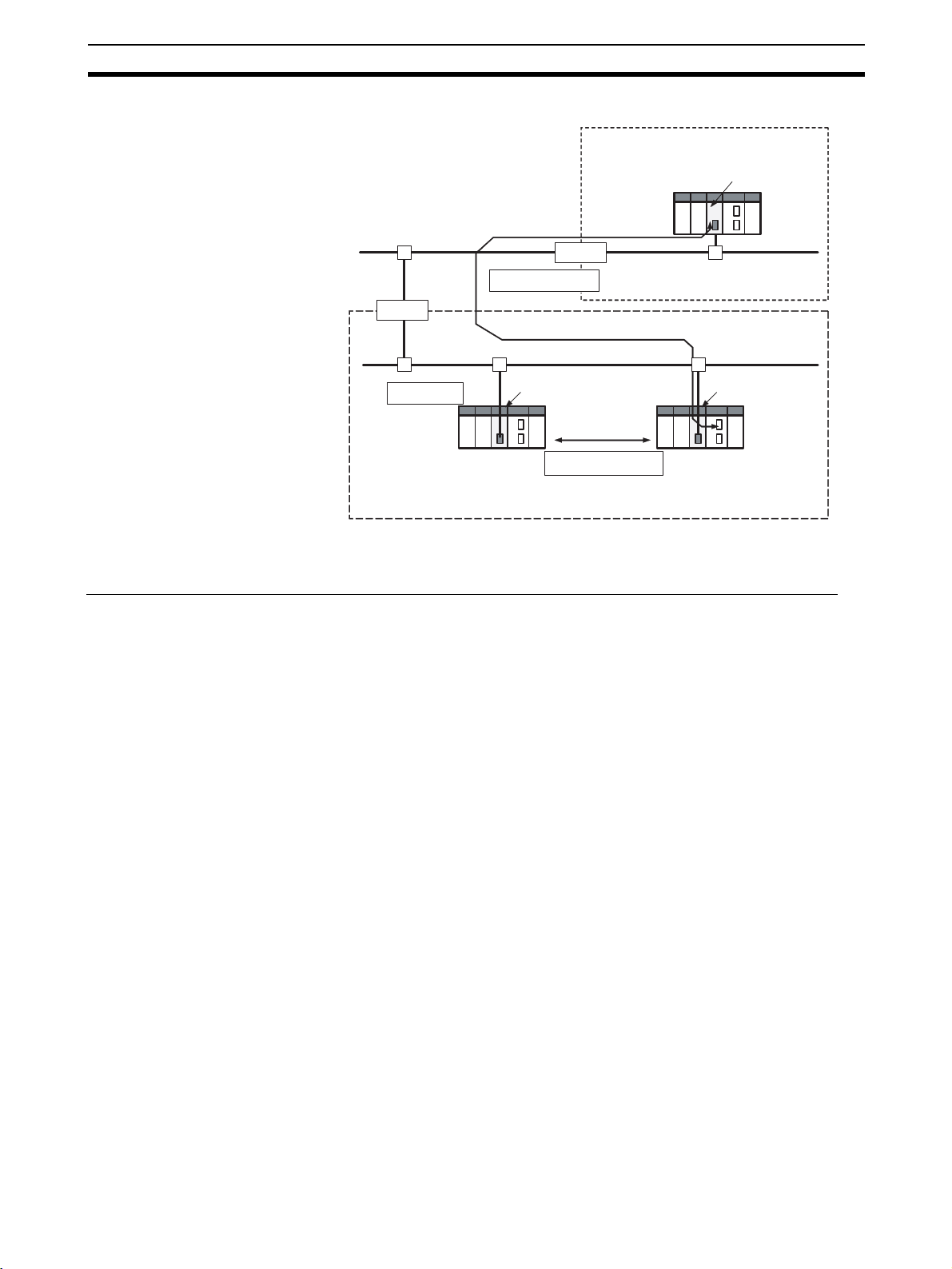
Ethernet Unit Function Guide Section 1-1
Intranet
Production line A
Ethernet Unit
Ethernet
Router
Mail
communications
FINS message
communications
Ethernet Unit
Connecting within the same segment:
Use FINS/UDP.
Router
Connecting through multiple segments:
Use FINS/TCP.
Production line B
PLC
FINS message
communications
Ethernet Unit
PLC
Memory Card
Reference SECTION 6 FINS Communications
Monitoring PLC Changes and Sending Equipment Status to the Operator by E-mail
Operation When the mail send function is used, automatic communications applications
via the Internet can be constructed relatively easily. With this Ethernet Unit,
the following mail triggers can be set as PLC changes. When these settings
can be used, no special ladder program is required for sending e-mail.
• When a particular bit (the Mail Send Switch) turns ON
• When values change in particular words (=, <>, <, <=, >=, >)
• When a particular bit changes (either OFF to ON or ON to OFF)
• When a change occurs at the Ethernet Unit (stored in error log)
• When a change occurs at the CPU Unit (e.g., a non-fatal error, a fatal
error, or a mode change)
• At regular intervals
The following data can be sent by e-mail:
• Text (user-created text strings (ASCII data), Ethernet Unit error log data,
and status data)
• Attached files (IOM data created automatically by the Ethernet Unit, data
tables, and files in File Memory)
To use the mail send function, there must be a separate SMTP server on the
network. When using the SMTP server of an Internet Service Provider (ISP),
security measures, such as POP before or SMTP, may be required. (This Unit
handles POP before SMTP.) In addition to the IP address, the host name used
for the DNS service can be specified for the SMTP/POP3 server.
5

Ethernet Unit Function Guide Section 1-1
Mail software
Receiving
e-mail
E-mail
Internet
IP router
Intranet
(Office floor)
Router
(Production line)
Ethernet Unit
PLC's I/O memory data
sent as attached file
Receiving
e-mail
Mail software
Router
Sending
e-mail
(Server room)
Ethernet
Firewall
Monitoring PLC changes and
sending equipment status to
the operator by e-mail
DNS server
POP3 server
SMTP server
SNTP server
Ethernet Ethernet
Reference SECTION 2 Mail Send Function in the Operation Manual Construction of
Applications
Receiving E-mail (Data and Files) at the PLC
Operation Use the mail receive function.
When the mail receive function is used, the PLC can be accessed through a
mail address, enabling remote applications via the Internet to be constructed
relatively easily. With the mail receive function, any of the following remote
commands can be specified as e-mail subjects.
• FileWrite (File Write)
• FileRead (File Read)
• FileDelete (File Delete)
• FileList (File List Read)
• UMBackup (User Memory
Backup)
• PARAMBackup (Parameter Area
Backup)
• IOMWrite (I/O Memory Write)
• IOMRead (I/O Memory Read)
To use the mail receive function, there must be a separate POP3 server on
the network. Aside from the IP address, the host name used for DNS service
can be specified for the POP3 server.
• ChangeMode (Operating Mode
Change)
• ErrorLogRead (Error Log Read)
• ErrorLogClear (Error Log Clear)
• MailLogRead (Mail Log Read)
• MailLogClear (Mail Log Clear)
• Test (Mail Test)
• FinsSend (FINS Command
Send)
6

Ethernet Unit Function Guide Section 1-1
Mail software
Sending e-mail
Internet
IP router
Firewall
(Server room)
Intranet
(Office floor)
Router
Writing command
File attachment enabled
Receiving e-mail
Receiving e-mail at the PLC
DNS server
POP3 server
SMTP server
SNTP server
Ethernet
Writing command
File attachment enabled
Ethernet
Sending e-mail
Router
(Production line)
Ethernet Unit
Mail software
Ethernet
Reference SECTION 3 Mail Receive Function in the Operation Manual Construction of
Applications
Exchanging Large Files between a Personal Computer and PLC
Operation Use the FTP server function.
The FTP server function makes it possible to log in to the Ethernet Unit from a
computer (FTP client) as required, and to specify folders and files to be transferred. The following items can be used as PLC File Memory.
• A Memory Card (mounted to the CPU Unit)
• EM File Memory (The portion of the EM Area in the CPU Unit's I/O memory used by the CX-Programmer as File Memory)
Reference SECTION 4 FTP Server Function in the Operation Manual Construction of
Applications
Creating an Original Communications Procedure Using TCP/IP (UDP/IP) for the Host
Application or Communicating with PLCs from Another Manufacturer
Operation Using the socket services function, create a communications application in
the ladder program.
With the socket services function, TCP/IP or UDP/IP can be used directly to
receive data. Use the socket services to create applications based on manipulating control bits or the CMND(490) instruction.
Reference SECTION 4 Socket Service Function in the Operation Manual Construction of
Applications
7

Fe at ur e s Section 1-2
Automatically Adjusting the PLC's Internal Clock at Regular Intervals
Operation Use the automatic clock adjustment function.
With the automatic clock adjustment function, the SNTP server's clock is
taken as the standard for automatically adjusting the built-in clock of the PLC
connected to the Ethernet Unit. The adjustment can be regularly executed at
a specified time (once a day) and it can be executed each time by the ladder
program.
To use the automatic clock adjustment function, there must be a separate
SNTP server on the network. Aside from the IP address, the host name used
for DNS service can be specified for the SNTP server.
Reference SECTION 5 Automatic Clock Adjustment Function in the Operation Manual
Construction of Applications
1-2 Features
Compatibility and Speed
The transmission medium has been upgraded to 100Base-TX, while compatibility with the functions and application interfaces of the existing Ethernet Unit
models (CS1W-ETN01, CS1W-ETN11, and CJ1W-ETN11) has been maintained. Moreover, processing speed has been improved so that the system
response performance for the same FINS message applications is now up to
four times faster.
Various Protocols Available on Ethernet
A variety of protocols makes available a wide range of applications for use on
an Ethernet network. The protocols that can be selected include sending and
receiving data by TCP/IP or UDP/IP (socket services), sending and receiving
commands by OMRON's standard protocol FINS, transferring files by FTP,
sending and receiving e-mail by SMTP/POP3, and automatically adjusting the
PLC's internal clock by SNTP.
A communications service can be selected according to need, allowing the
PLC to be flexibly integrated with the Ethernet information network.
Communications by UDP/IP and TCP/IP (Socket Services Function)
The standard Ethernet protocols, UDP/IP and TCP/IP, are supported, making
it possible to communicate with a wide range of devices, workstations, computers, and Ethernet Units from other manufacturers.
Up to eight ports can be used for various protocols, enabling the use of various applications.
Simplified Socket Services
Without using the CMND(490) instruction, the socket services function for
TCP or UDP can be simplified by presetting parameters and using dedicated
bits. In addition, the size of received data accumulated in the reception buffer
is now stored, and a Data Received Flag has been added. These new features eliminate the need for ladder programs to monitor the timing for completion of instructions and socket service processing, and thus reduce the
amount of labor required for program development.
8

Fe at ur e s Section 1-2
Starting with unit version 1.5, the performance of sending and receiving has
been improved using optional settings for the TCP or UDP socket services
using specific bits in memory. Also, a linger socket option has been added to
the TCP socket services. Specifying this option enables open processing
immediately with the same port number without having to wait (approximately
1 min.) until the port number opens after the socket closes.
Improved FINS Message Communications
The following functions have been improved over previous Ethernet Unit models. They allow the scale of the system to be increased, and can give greater
flexibility to the system configuration including the host computer.
• Expanded number of nodes (to 254 max., from 126 max.)
• Communications are now enabled even if the host computer's IP address
is dynamic. (DHCP client computers can be handled, including TCP/IP
and UDP/IP.)
→ Previously IP addresses for host computers could be fixed only.
→ For Ethernet Units with Unit Ver. 1.3 or later, the Unit can be protected
against access from nodes with dynamically changed IP addresses (set
to be fixed only).
• An automatic client FINS node address allocation function now makes it
possible to connect online to the PLC even if no FINS node address has
been set for the host computer.
→ Previously online connection to the PLC was possible only after a FINS
node address was set for the host computer.
• FINS message communications are now enabled in TCP/IP (with up to 16
simultaneous connections), so a system can now utilize FINS message
communications in both UDP/IP and TCP/IP.
→ Previously only UDP/IP could be used.
• Multiple FINS applications (such as the CX-Programmer) on the same
computer can now be connected online to the PLC via Ethernet (in either
TCP/IP or UDP/IP).
→ Previously when one FINS application on a computer was connected
online to the PLC, it was impossible to connect any other at the same
time.
Transferring Data Files between Host Computers (FTP Server Function)
A built-in FTP server function enables data files in the PLC to be read from a
workstation or computer with an FTP client function, and for data to be written
to the PLC. Large amounts of data can be transferred at a time from clients,
without requiring ladder programming.
Additional E-mail Functions
With previous Ethernet Unit models (CS1W-ETN01/CS1W-ETN11/CJ1WETN11), e-mail could sent only from the Ethernet Unit, and the data that could
be sent was limited to user-created ASCII text data and system data. Now the
following e-mail functions have been added.
Mail Receive Function
(Receiving Commands for
the PLC by E-mail)
E-mail File Attachment
Function
Commands for the PLC (mail remote commands) can be written into e-mail,
and the Ethernet Unit can receive them, execute them, and send responses
by e-mail.
This function can be linked to the CS/CJ File Memory function.
9

Fe at ur e s Section 1-2
• The Ethernet Unit can automatically generate data files (6,000 words
maximum per file) from the CPU Unit's I/O memory status, and send them
to specified e-mail addresses as e-mail attachments. It can also send program files from the Memory Card (up to 1 MB) to specified e-mail
addresses as e-mail attachments.
• In addition to using the existing Mail Send Switch, or having e-mail sent at
regular intervals, it is possible to set triggers for sending e-mail (for example, by having e-mail sent when a PV in the CPU Unit's I/O memory
reaches a certain value (size comparison), or when the bit at a specified
address turns ON).
• Up to eight of these e-mail send conditions (destination, trigger type, etc.)
can be preregistered so that e-mail will be sent automatically whenever
the conditions are met.
Note The e-mail functions require a separate mail server (SMTP/POP3).
Automatic PLC Internal Clock Adjustment
The built-in clock of the PLC connected to the Ethernet can be automatically
adjusted, with the SNTP server clock taken as the standard. Automatic adjustments through the entire system enable the various records generated by production equipment to be managed according to clock information and
analyzed.
Note The automatic clock adjustment requires a separate SNTP server.
Specification of Servers by Host Name
In addition to directly specifying the IP address for a SMTP, POP3, or SNTP
server, it is also possible (by means of the Ethernet Unit's DNS client function)
to specify the server by host name. This enables automatic searches for IP
addresses for purposes such as system checking, even when the IP
addresses for servers have been changed.
Note (1) A separate DNS server is required to specify servers by host name using
DNS.
(2) The IP address is specified directly for the DNS server.
Classless IP Address Settings Using CIDR
Starting from unit version 1.5, it is possible to use classless inter-domain routing (CIDR) by specifying the subnet class using an option setting. This
enables greater flexibility in specification by eliminating the need to have the
network ID component of the IP address be dependent on the class.
Use Web Function to Read Ethernet Unit Settings and Status
A Web function is provided in Ethernet Units with Unit Ver. 1.3 or later. This
enables use of a Web browser to read the Ethernet Unit’s system settings and
statuses.
Network Connection with Controller Link
The Ethernet information network can be connected to the Controller Link
control system network by using the FINS communications service function.
This enables a PLC on a Controller Link network to be monitored from a PLC
on an Ethernet network, and it allows data to be exchanged between them.
10

System Configuration Section 1-3
Full Range of Functions for Handling Troubles
A full range of functions is provided for promptly handling any troubles that
may arise.
• Self-diagnostic function when power is turned ON
• Remote node connection check by PING command
• Remote node connection check by internode test
• Error log for recording error information when an error occurs
• Notification by e-mail when an error occurs
1-3 System Configuration
1-3-1 System Configuration
CX-Programmer
CX-Integrator
FinsGateway
(3) Hub
100 m
max.
(2) Twisted-pair cable
(1) CS1W-ETN21
Ethernet Unit
(100Base-TX)
CS-series
PLC
1-3-2 Devices Required for Constructing a Network
The basic configuration for a 100Base-TX Ethernet System consists of one
hub to which nodes are attached in star form using twisted-pair cable.
The devices shown in the following table are required to configure a network
with 100Base-TX-type CS1W-ETN21 and CJ1W-ETN21 Ethernet Units, so
prepare them in advance.
Network device Contents
(1) CS-series Ethernet
Units (CS1W-ETN21)
or CJ-series Ethernet
Units (CJ1W-ETN21)
(2) Twisted-pair cable This is twisted-pair cable for connecting 100Base-TX-type
(3) Hub This is a relay device for connecting multiple nodes in a
These Ethernet Units are Communications Units that
connect a CS-series or CJ-series PLC to 100Base-TX
Ethernet networks. (They can also be used as 10Base-T.)
Ethernet Units to the hub, with an RJ45 Modular Connector at each end.
Use a category 3, 4, 5, or 5e UTP (unshielded twistedpair) or STP (shielded twisted-pair) cable.
star LAN.
(1) CJ1W-ETN21
Ethernet Unit
(100Base-TX)
CJ-series
PLC
Recommended Hubs For details on recommended devices for constructing a network, refer to 2-4
Network Installation.
11

System Configuration Section 1-3
1-3-3 Setup Area and Related Peripheral Devices
Making Settings in the
CPU Bus Unit System
Setup Area (with the CXProgrammer)
For the Ethernet Unit to function as a node on an Ethernet network, make the
settings, as required, in the CPU Bus Unit System Setup Area allocated in
non-volatile memory in the CPU Unit.
Use the CX-Programmer to make the settings (by connecting online from the
I/O Table Window, selecting the Ethernet Unit, and then selecting Unit Setup).
Each time the Ethernet Unit is turned ON or restarted, it reads and uses the
contents of the CPU Bus Unit System Setup Area as the settings for the communications services.
If setting items for expanded functionality of the Ethernet Unit are not displayed, make the settings after updating the Support Software using an auto
update or by using the Web function of the Ethernet Unit.
Personal computer
running Windows
CX-Programmer
Unit Setup
Ethernet Unit
CPU Bus Unit System
Setup Area
CS/CJ-series CPU Unit
Making Settings in the
Routing Table Area (with
CX-Integrator)
Middleware for FINS
Communications
Applications on a
Personal Computer
(FinsGateway)
OMRON Communications Units use OMRON's original FINS network system.
Make the settings for the FINS network and the relay path, as required, in the
Routing Table Area allocated to the non-volatile memory in the CPU Unit.
Use CX-Integrator to make the settings. (CX-Integrator is software that comes
with the CX-One and is automatically installed when the CX-One is installed.)
Each time the Ethernet Unit is turned ON or restarted, it reads the contents of
the Routing Table Area as the settings for FINS network.
Personal computer
running Windows
CX-Integrator
Routing table
settings
Ethernet Unit
Routing Table Area
CS/CJ-series CPU Unit
FinsGateway can be used as middleware when constructing communications
applications on a personal computer for a FINS network, using Visual C++ or
Visual BASIC. The CX-Programmer and CX-Integrator can also be connected
online through FinsGateway. When FINS/UDP is used in the FINS communications service, all versions of FinsGateway can be used.
When FINS/TCP is used in the FINS communications service, only FinsGateway Version 2003 or higher can be used.
12

System Configuration Section 1-3
t
When the CX-Programmer and CX-Integrator are connected online by FINS/
TCP, FinsGateway Version 2003 or higher must be used.
For CX-Programmer Ver. 4.0 or higher, FINS/TCP can be used to directly connect to the PLC online.
Personal computer running Windows
User-created
software
FinsGateway
CX-Programmer
Windows
Ethernet Uni
CS/CJ-series CPU Unit
13

Specifications Section 1-4
1-4 Specifications
1-4-1 General Specifications
CS-series Ethernet Unit
Item Specifications
Model number CS1W-ETN21
Type 100Base-TX (Can be used as 10Base-T)
Applicable PLCs CS-series PLCs
Unit classification CS-series CPU Bus Unit
Mounting location CPU Rack or Expansion Rack
Number of Units that can be mounted 4 max. (including Expansion Racks)
Tr an s fe r
specifications
Current consumption (Unit) 380 mA max. at 5 V DC
Weight 200 g max.
Dimensions 35 × 130 × 101 mm (W × H × D)
Other general specifications Conform to general specifications for the SYSMAC CS Series.
Media access method CSMA/CD
Modulation method Baseband
Transmission paths Star form
Baud rate 100 Mbit/s (100Base-TX) 10 Mbit/s (10Base-T)
Transmission media Unshielded twisted-pair (UDP) cable
Categories: 5, 5e
Shielded twisted-pair (STP) cable
Categories: 100 Ω at 5, 5e
Transmission distance 100 m (distance between hub and node)
Number of cascade con-
nections
No restrictions if switching hubs are used.
Unshielded twisted-pair (UDP) cable
Categories: 3, 4, 5, 5e
Shielded twisted-pair (STP) cable
Categories: 100 Ω at 3, 4, 5, 5e
CJ-series Ethernet Unit
Item Specifications
Model number CJ1W-ETN21
Type 100Base-TX (Can be used as 10Base-T)
Applicable PLCs CJ-series PLCs
Unit classification CJ-series CPU Bus Unit
Mounting location CPU Rack or Expansion Rack
Number of Units that can be mounted 4 max. (including Expansion Racks)
Tr an s fe r
specifications
Current consumption (Unit) 370 mA max. at 5 V DC
Weight 100 g max.
Dimensions 31 × 90 × 65 mm (W × H × D)
Other general specifications Conform to general specifications for the SYSMAC CJ Series.
Media access method CSMA/CD
Modulation method Baseband
Transmission paths Star form
Baud rate 100 Mbit/s (100Base-TX) 10 Mbit/s (10Base-TX)
Transmission media Unshielded twisted-pair (UDP) cable
Categories: 5, 5e
Shielded twisted-pair (STP) cable
Categories: 100 Ω at 5, 5e
Transmission distance 100 m (distance between hub and node)
Number of cascade con-
nections
No restrictions if switching hubs are used.
Unshielded twisted-pair (UDP) cable
Categories: 3, 4, 5, 5e
Shielded twisted-pair (STP) cable
Categories: 100 Ω at 3, 4, 5, 5e
14

Specifications Section 1-4
1-4-2 Dimensions
CS1W-ETN21
CJ1W-ETN21
130
ETN21
RUN
ERC
SD
RD
LNK
NODE
NO.
100BASE-TX
Front
UNIT
0
×16
10BASE-T
NO.
100M
ERH
TCP
FTP
HOST
0
1
0
1
×16
10135
(Unit: mm)
Back
• Unit Version 1.5 or Later
31
90 2.72.7
ETN21
RUN ERC SD RD
ERH TCP FTP HOST100M
5
4
6
3
7
2
8
1
9
0
A
F
B
E
C
D
100BASE-TX
10BASE-T
x16
LINK
5
4
UNIT
6
3
7
2
8
1
9
0
A
F
No.
B
E
C
D
5
4
NODE
6
3
7
2
8
1
9
0
A
F
No.
B
E
C
D
0
1
x16
• Unit Version 1.4 or Earlier
31
90 2.72.7
ETN21
RUN ERC SD RD
ERH TCP FTP HOST100M
100BASE-TX
10BASE-T
LINK
5
4
UNIT
6
3
7
2
8
1
9
0
A
F
No.
B
E
C
D
5
4
NODE
6
3
7
2
8
1
9
0
A
F
No.
B
E
C
D
1
x16
5
4
6
3
7
2
8
1
9
0
A
F
B
E
C
D
0
x16
65
(Unit: mm)
15

Specifications Section 1-4
1-4-3 Software Configuration
The software supported by the Ethernet Unit runs in the layers shown in the
following diagram. The components that form the various layers are defined
below the diagram.
11. SMTP
CS/CJ-series CPU Unit
FINS communi-
Socket
services
FINS/UDP
5. UDP
cation service
7. FINS
2. IP
1. Ethernet (Ver. 2.0)
1,2,3... 1. Ethernet (Ver. 2.0)
The Version 2.0 Ethernet frame format is used for communications.
2. IP (Internet Protocol)
Transfers datagrams to destination nodes using IP addresses.
3. ICMP (Internet Control Message Protocol)
Supports IP communications by signalling errors in data transfers.
4. ARP (Address Resolution Protocol)
Determines the Ethernet address (i.e., physical address) by broadcasting
based on the target IP address.
5. UDP (User Datagram Protocol)
Performs data communications. Data resends, priority control, flow control,
and other measures to ensure communications reliability are not performed for UDP communications, so the transmitted data may not arrive at
the destination node. To increase reliability, it is necessary to program special measures into the user applications.
6. TCP (Transmission Control Protocol)
Performs communications after establishing a connection (i.e., a virtual circuit) with the destination node, providing a highly reliable communications
service.
7. FINS (Factory Interface Network Service)
A protocol that sends messages between PLCs on any of various OMRON
FA networks. To ensure that transmitted messages arrive at the destination
node, it is necessary to program special measures such as retry processing into the user's applications.
8. FTP (File Transfer Protocol)
Transfers data files.
9. SMTP (Simple Mail Transfer Protocol)
A communications protocol for sending e-mail by TCP/IP.
10. POP3 (Post Office Protocol Ver. 3.0)
A communications protocol for receiving e-mail by TCP/IP.
11. SNTP (Simple Network Time Protocol)
A communications protocol for automatic clock adjustment by UDP/IP.
12. DNS (Domain Name System)
A communications protocol for determining IP address names according
to UDP/IP and TCP/IP.
FINS/TCP
Socket
services
3. ICMP 4. ARP
E-mail
transmission
6. TCP
E-mail
reception
10. POP3
Memory Card /
EM File Memory
FTP
8. FTP server9. SMTP
CS/CJ-series
CPU Unit
Ethernet
Unit
16

Overview of Communications Functions Section 1-5
1-5 Overview of Communications Functions
1-5-1 FINS Communications Service
Basic Functions FINS commands can be sent to or received from other PLCs or computers on
the same Ethernet network by executing SEND(090), RECV(098), or
CMND(490) instructions in the ladder diagram program. This enables various
control operations such as the reading and writing of I/O memory between
PLCs, mode changes, and file memory operations.
Ethernet
UDP or TCP
IP
CS/CJ-series
CPU Unit
Ethernet Unit Ethernet Unit Ethernet Unit
FINS IP FINS
UDP or TCP
User program
SEND(090),
RECV(098), or
CMND(490)
instruction
Executing, from the host computer, FINS commands with UDP/IP or TCP/IP
headers enables various control operations, such as the reading and writing
of I/O memory between PLCs, mode changes, and file memory operations.
For example, it is possible to connect online via Ethernet from FINS communications applications such as the CX-Programmer, and to perform remote programming and monitoring. (See note.)
Note Use CX-Programmer version 4.0 to use TCP/IP. For lower versions of CX-Pro-
grammer, FinsGateway Version 2003 or higher is required to use TCP/IP.
Ethernet
UDP or TCP
IP
FINS
CS/CJ-series
CPU Unit
Ethernet Unit
The FINS gateway function enables access to PLCs on not only the same
Ethernet network but on various other networks, including SYSMAC LINK and
Controller Link.
Upgraded Functions With the CS1W-ETN21 and CJ1W-ETN21, the following functions have been
upgraded.
• The FINS communications service can be executed not only with UDP/IP
but also with TCP/IP, and it is even possible to use FINS communications
with both UDP/IP and TCP/IP together on the same network. Using TCP/
IP makes FINS communications highly reliable.
17

Overview of Communications Functions Section 1-5
• Even if the IP address and UDP port number of the host computer (a
DHCP client computer) are changed, it is still possible for the host computer to send FINS commands to PLCs on the Ethernet network and to
receive responses. When UDP is used, either the automatic generation
(dynamic) method or the IP address table method must be selected for IP
address conversion. When TCP is used, changes in IP address and TCP
port numbers are handled automatically.
• Multiple FINS applications (CX-Programmer and user-created application
programs) at the same computer can be connected online to a PLC via
Ethernet (using either TCP/IP or UDP/IP).
1-5-2 Socket Services
The socket services allow devices on the Ethernet to send and receive various data using either the UDP or TCP protocol.
Manipulating Dedicated
Control Bits
One way to use socket services is to set the required parameters in the
parameter area allocated in the DM Area, and then to request particular UDP
or TCP socket services by turning ON dedicated control bits in memory. When
the Ethernet Unit has completed the requested process, the same bit is
turned OFF to provide notification. Data that is sent or received is automatically handled according to the I/O memory locations specified in the parameter area.
There is no need to execute the CMND(490) instruction or to monitor the completion timing and actual processing of the instruction, so this helps to simplify
ladder programming.
A total of eight ports (UDP and TCP combined) can be used for socket services.
Starting with unit version 1.5, the performance of sending and receiving has
been improved by using the option settings.
UNIX computer, etc.
(node with socket
services interface)
Ethernet
TCP/UDP
protocol
CS/CJ-series
CPU Unit
Ethernet Unit
18
TCPUDP
TCP/UDP
protocol
IP
Socket
Ethernet Unit CS/CJ-series
Service request switch
Parameters
CPU Unit

Overview of Communications Functions Section 1-5
Executing CMND(490) Another way to use socket services is to request a UDP or TCP socket ser-
vice by sending a FINS command to the Ethernet Unit by executing
CMND(490) from the CPU Unit. When the Ethernet Unit receives the socket
service request, it returns a response to the CPU Unit to confirm that it
received the request, and then begins the requested processing. When the
processing is completed, the results are stored in the Results Storage Area in
the CPU Unit.
Eight TCP ports and eight UDP ports can be used.
Improved TCP Socket
Interface
The TCP socket interface has been improved. The size of received data accumulated in the reception buffer is now stored, and a Data Received Flag has
been added, enabling the TCP socket's receive program to be executed after
the required data has been accumulated in the Ethernet Unit's reception
buffer. The keep-alive setting has also been enabled for TCP socket services.
UNIX computer, etc.
(node with socket
services interface)
Ethernet
TCP/UDP
protocol
CS/CJ-series
CPU Unit
TCP protocol
UDP protocol
IP
Socket interface
Ethernet Unit CS/CJ-series
TCPUDP
Socket
FINS
commands
FINS
responses
Processing
results
Ethernet Unit
CMND
Results Storage
Area
CPU Unit
19

Overview of Communications Functions Section 1-5
1-5-3 FTP Server Function
The Ethernet Unit has a built-in FTP server, so other computers on the Ethernet can read or write individual files on a Memory Card mounted to the CPU
Unit or in EM File Memory. This allows files to be exchanged between the host
computer and the PLC, with the host computer functioning as an FTP client
and the PLC as an FTP server.
Host computer
(FTP client)
Ethernet
Host computer to PLC PLC to host computer
File data
1-5-4 Mail Send Function
This function automatically sends data in the CPU Unit's I/O memory (or a file
on a Memory Card) as an e-mail attachment from the Ethernet Unit to specified e-mail addresses when a pre-specified PLC condition is met. User-created data (in ASCII), error log data, and status data in the CPU Unit can all be
sent as text.
E-mail can be sent over the Internet, and not just within the intranet.
FTP commands
CS/CJ-series
CPU Unit
Ethernet Unit
Memory Card or
EM File Memory
SMTP server
Memory Card or
EM File Memory
File data
Memory Card or
EM File Memory
20
Ethernet
E-mail
CS/CJ-series
CPU Unit
Ethernet Unit
The e-mail can be sent on any of the following types of timing:
When the Mail Send Switch turns ON
When the value of a specified word meets a condition
When the value of a specified bit meets a condition
When an error is recorded in the Ethernet Unit's error log
When the CPU Unit's operating mode is changed
At regular intervals
Note (1) Depending on the Internet service provider (ISP), the use of POP before
SMTP may be defined from the standpoint of security considerations.
(This Unit handles POP before SMTP.)

Overview of Communications Functions Section 1-5
(2) An SMTP server is required to use the mail send function.
(3) Mail server settings require specialized knowledge, so they should al-
ways be handled by the network administrator.
(4) Be sure that you have a clear understanding of the mail system before us-
ing this function.
(5) Mail my not always be delivered. Depending on factors such as the con-
dition of the network, mail that has been sent may not arrive at its destination.
1-5-5 Mail Receive Function
With the mail receive function, the user writes a command into the e-mail and
then sends the e-mail to the Ethernet Unit. The Ethernet Unit receives e-mail
at regular intervals, executes the commands, and sends back responses by email.
E-mail can be received over the Internet, and not just from within the intranet.
POP3 server
Ethernet
E-mail
CS/CJ-series
CPU Unit
Ethernet Unit
The following types of commands can be sent to the PLC: I/O memory read
and write, backup, operating mode changes, and file transfers (of 1 Mbyte or
less).
Note (1) A POP3 server is required to use the mail receive function.
(2) Mail server settings require specialized knowledge, so they should al-
ways be handled by the network administrator.
(3) Be sure that you have a clear understanding of the mail system before us-
ing this function.
(4) Mail may not always be delivered. Depending on factors such as the con-
dition of the network, mail that has been sent may not arrive at its destination.
21

Overview of Communications Functions Section 1-5
1-5-6 Automatic Clock Adjustment Function
The Ethernet Unit can acquire clock information from the SNTP server at a
particular time or when a dedicated bit turns ON, and it can refresh the internal clock information of the CPU Unit to which it is mounted.
SNTP server
Ethernet
Clock information
CS/CJ-series
CPU Unit
Note (1) An SNTP server is required to use this function.
(2) SNTP server settings require specialized knowledge, so they should al-
ways be handled by the network administrator.
(3) Be sure that you have a clear understanding of the mail system before us-
ing.
(4) When using the Internet, depending on the condition of the network it
may not be possible to acquire the clock information.
Ethernet Unit
1-5-7 Specifying Servers by Host Name
POP servers, SMTP servers, and SNTP servers can be specified by host
name rather than by IP address by using of the DNS client function.
DNS server
CS/CJ-series
CPU Unit
Note A DNS server is required to specify servers by host name.
IP address
Host name
Ethernet
Ethernet Unit
22

Nomenclature and Functions Section 1-6
1-6 Nomenclature and Functions
This section describes Ethernet Unit component names, settings, and LED
indicators.
1-6-1 Component Names
CS-series Ethernet Units
CS1W-ETN21 (100Base-TX)
Front
ETN21
RUN
ERC
RD
LNK
NODE
NO.
100M
ERH
SD
TCP
FTP
HOST
UNIT
0
NO.
0
1
1
×16
×16
Indicators
Display the operating status of the Unit.
Unit Number Switch
0
Used to set the Ethernet Unit's unit
number in one digit hexadecimal.
Node Address Switches
Used to set the Ethernet Unit's FINS
node number in two digits hexadecimal.
100BASE-TX
10BASE-T
Ethernet Connector
Used to connect the Ethernet twisted-pair cable.
Each communications device connected to the Ethernet network is allocated
a unique Ethernet address. For the Ethernet Unit, this Ethernet address is
shown on the right side of the Unit as a 12-digit hexadecimal number.
CS1W-ETN21
ETHERNET UNIT
Lot No.
OMRON Corporation MADE IN JAPAN
@@@@@@@@@@@@
Ethernet Address
Ethernet address (12 digits)
Note The Ethernet address can also be checked using the FINS command, CON-
TROLLER DATA READ. For details, refer to 7-3-2 CONTROLLER DATA
READ on page 162.
23

Nomenclature and Functions Section 1-6
CJ-series Ethernet Units
CJ1W-ETN21 (100Base-TX)
Front
• Unit Version 1.5 or Later • Unit Version 1.4 or Earlier
Slider
For mounting to other Units.
Indicators
ETN21
RUN ERC SD RD
ERH TCP FTP HOST100M
5
4
6
3
7
2
8
1
9
0
A
F
B
E
C
D
1
x16
ETN21
RUN
LINK
5
4
UNIT
6
3
7
2
8
1
9
0
A
F
No.
B
E
C
D
5
4
NODE
6
3
7
2
8
1
9
0
A
F
No.
B
E
C
D
0
x16
ERC SD RD
ERH TCP FTP HOST
100M
LINK
5
4
UNIT
6
3
7
2
8
1
9
0
A
F
No.
B
E
C
D
5
4
NODE
6
3
7
2
8
1
9
0
A
F
No.
B
E
C
1
x16
5
4
6
3
7
2
8
1
9
0
A
F
B
E
C
D
0
x16
Display the operating status of the Unit.
Unit Number Switch
Used to set the Ethernet Unit's unit
number in one digit hexadecimal.
Node Number Switches
Used to set the Ethernet Unit's FINS
node number in two digits hexadecimal.
100BASE-TX
10BASE-T
Note An IP address label is provided with the Unit. Writing the IP address and the
100BASE-TX
10BASE-T
Ethernet Connector
Used to connect the Ethernet twisted-pair cable.
Mounting Pin for DIN Track
Used when mounting the Unit to DIN Track.
Slider
For mounting to other Units.
subnet mask on this label and then attaching it to the front of the Unit allows
the IP address and subnet mask to be easily confirmed.
24

Nomenclature and Functions Section 1-6
• Unit Version 1.5 or Later • Unit Version 1.4 or Earlier
ETN21
RUN ERC SD RD
ERH TCP FTP HOST100M
4
3
2
1
0
F
E
5
4
6
3
7
2
1
0
A
F
B
E
C
D
IP ADDRESS
4
3
2
8
1
9
0
F
E
1
x16
133.113. 0. 42
SUBNET MASK
255.255.255.0
100BASE-TX
10BASE-T
Each communications device connected to the Ethernet network is allocated
a unique Ethernet address. For the Ethernet Unit, this Ethernet address is
shown on the right side of the Unit as a 12-digit hexadecimal number.
5
C
D
5
C
D
6
7
8
9
A
B
6
7
8
9
A
B
LINK
UNIT
No.
NODE
No.
x16
ETN21
RUN ERC SD RD
ERH TCP FTP HOST100M
0
IP ADDRESS
LINK
5
4
UNIT
6
3
7
2
8
1
9
0
A
F
No.
B
E
C
D
5
4
NODE
6
3
7
2
8
1
9
0
A
F
No.
B
E
C
D
1
x16
5
4
6
3
7
2
8
1
9
0
A
F
B
E
C
D
0
x16
Example
IP ADDRESS
133.113. 0. 42
SUBNET MASK
255.255.255.0
Attach the label to the front
of the Ethernet Unit between
the node number switches
and the Ethernet connector.
133.113. 0. 42
SUBNET MASK
255.255.255.0
100BASE-TX
10BASE-T
Note The Ethernet address can also be checked using the FINS command, CON-
1-6-2 Indicators
CJ1W-ETN21
ETHERNET UNIT
Lot No.
OMRON Corporation MADE IN JAPAN
@@@@@@@@@@@@
Ethernet Address
Ethernet address (12 digits)
TROLLER DATA READ. For details, refer to 7-3-2 CONTROLLER DATA
READ on page 162.
The status of the indicators show the operating status of the Ethernet Unit, as
shown below.
CS1W-ETN21
(100Base-TX)
ETN21
RUN
ERC
SD
RD
LNK
100M
ERH
TCP
FTP
HOST
CJ1W-ETN21
(100Base-TX)
ETN21
RUN
ERC SD RD
ERH TCP FTP HOST
100M
LNK
25

Nomenclature and Functions Section 1-6
Indicator Color Status Meaning
RUN Green Not lit Operation stopped
Hardware error
Lit Normal operation
100M
(Transfer speed)
ERC
(Ethernet Unit error)
ERH
(CPU Unit error)
SD
(Send Data)
RD
(Receive Data)
LNK
(Link status)
TCP
(TCP socket in use)
FTP
(FTP Server Service)
HOST
(Server connection sta-
tus)
Green Not lit 10 Mbps (10Base-T)
Lit 100 Mbps (100Base-TX)
Red Not lit Unit normal
Lit Node address not between 1 and 254
A hardware (e.g., internal memory) error has occurred.
Red Not lit CPU Unit normal
Lit An error has occurred at the CPU Unit.
There is an error in the I/O table, unit number, unit setup, or routing
table settings.
Flashing An illegal IP address has been set. With automatic address gener-
ation, the rightmost two digits of the IP address do not match the
node address.
Yellow Not lit Not sending data (ready to send)
Lit Sending data
Yellow Not lit Not receiving data (ready to receive)
Lit Receiving data
Yellow Not lit Link not established between hubs.
Lit Link established between hubs.
Yellow Not lit None of the eight TCP sockets provided for socket services is in
use.
Lit At least one of the eight TCP sockets provided for socket services
is in use.
Yellow Not lit FTP server on standby.
Lit FTP server operating (one user connected).
Yellow Not lit Server (DNS, SMTP, POP3, or SNTP) not being used.
Flashing An error has occurred in the server connection.
Lit The server connection is normal.
26

Comparison with Previous Models Section 1-7
1-7 Comparison with Previous Models
Item Previous models New models
Model number CS1W-ETN11
CJ1W-ETN11
Physical layer 10Base-T 100Base-TX, 10Base-T
Number of nodes 126 254
PLC maintenance via the Internet Not possible to send FINS
commands from a personal
computer to the PLC via the
Internet.
Server specification Specification by IP address
Communications service
FINS communications
service
Mail functions Mail send function only E-mail attachments with I/O memory data
FTP server function Same
Socket services function --- The following features have been added to
Automatic clock information
adjustment
Automatic IP
address acquisition (DHCP client) by personal
computer
FINS communications with personal computers
without fixed
node addresses
Handling TCP/IPWith FINS communications,
Simultaneous
connection of
multiple applications in a personal computer
only
Not possible for a computer
automatically acquiring IP
addresses to send commands
to the PLC and receive
responses.
Not possible Possible (with Automatic allocation by
only UDP/IP possible.
Not possible Possible (with both UDP/IP and TCP/IP)
Not possible CPU Unit built-in clock can be adjusted from
CS1W-ETN21
CJ1W-ETN21
Can send commands (including FINS commands) by e-mail over the Internet from a
personal computer to the PLC (using the
mail receive function).
Specification by IP address or by host name
(using the DNS client function)
A computer automatically acquiring IP
addresses can send commands to the PLC
and receive responses.
(UDP/IP: By automatic generation
(dynamic) IP address conversion method;
TCP/IP: Automatic)
Ethernet Unit)
(Client FINS automatic node address allocation function, TCP/IP only)
With FINS communications, both UDP/IP
and TCP/IP possible.
are now possible for the mail send function.
(SMTP client function, file attachment function)
With the mail receive function, commands
can be received from the PLC. (POP3 client
function, mail receive function)
the TCP socket services function:
•Use of keep-alive
• Number of bytes of data received for TCP
socket Nos. 1 to 8
• Status of TCP socket Nos. 1 to 8: Data
Received Flag
SNTP server. (SNTP client function)
27

Unit Version Upgrade Information Section 1-8
1-8 Unit Version Upgrade Information
The details of the upgrade to the Ethernet Unit version are as follows:
■ Unit Version 1.3
Upgrade Details
Web function added The unit settings and status monitoring for the Ethernet Unit
Function prohibiting
access using FINS/
UDP from nodes
with dynamically
changed IP
addresses
■ Unit Version 1.4
Upgrade Details
ETN11-compatible
mode added to the
ETN21 settings for
FINS/UDP.
■ Unit Version 1.5
Upgrade Details
Added CIDR function
to subnet mask settings.
Added option for
high-speed socket
services.
Added linger option
to socket options for
TCP open request.
Changed position of
node address setting switches (CJ1WETN21 only)
can be easily performed from a Web browser.
Access to change the remote IP address from a node using
FINS/UDP can be prohibited (IP address protection).
A mode compatible with the CS1W-ETN11/CJ1W-ETN11 was
added in the operating specifications for FINS/UDP messages
sent from a different UDP port number than the FINS/UDP
port number set in the Ethernet Unit.
An option setting has been added to the subnet mask settings
to enable CIDR. Enabling CIDR enables using the IP address
with classless subnet mask settings.
Enabling high-speed socket services improves the performance of sending and receiving for socket services using specific bits. If high-speed socket services are disabled,
performance is the same as previously.
It is possible to specify the linger option in the option settings
for the TCP open request (both passive and active).
The position of the node address setting switches was
changed. The setting method and setting range are the same
as previously.
28

SECTION 2
Installation and Initial Setup
This section explains how to install the Ethernet Unit and make the initial settings required for operation.
2-1 Overview of Startup Procedure. . . . . . . . . . . . . . . . . . . . . . . . . . . . . . . . . . . . 30
2-2 Switch Settings . . . . . . . . . . . . . . . . . . . . . . . . . . . . . . . . . . . . . . . . . . . . . . . . 31
2-2-1 CS-series Ethernet Units. . . . . . . . . . . . . . . . . . . . . . . . . . . . . . . . . . 31
2-2-2 CJ-series Ethernet Units . . . . . . . . . . . . . . . . . . . . . . . . . . . . . . . . . . 32
2-3 Mounting to a PLC . . . . . . . . . . . . . . . . . . . . . . . . . . . . . . . . . . . . . . . . . . . . . 33
2-3-1 Mounting to a CS-series PLC. . . . . . . . . . . . . . . . . . . . . . . . . . . . . . 33
2-3-2 Mounting to a CJ-series PLC . . . . . . . . . . . . . . . . . . . . . . . . . . . . . . 33
2-4 Network Installation . . . . . . . . . . . . . . . . . . . . . . . . . . . . . . . . . . . . . . . . . . . . 34
2-4-1 Basic Installation Precautions. . . . . . . . . . . . . . . . . . . . . . . . . . . . . . 34
2-4-2 Recommended Products . . . . . . . . . . . . . . . . . . . . . . . . . . . . . . . . . . 35
2-4-3 Precautions . . . . . . . . . . . . . . . . . . . . . . . . . . . . . . . . . . . . . . . . . . . . 35
2-4-4 Using Contact Outputs (Common to All Units) . . . . . . . . . . . . . . . . 37
2-5 Connecting to the Network . . . . . . . . . . . . . . . . . . . . . . . . . . . . . . . . . . . . . . . 38
2-5-1 Ethernet Connectors . . . . . . . . . . . . . . . . . . . . . . . . . . . . . . . . . . . . . 38
2-5-2 Connecting the Cable . . . . . . . . . . . . . . . . . . . . . . . . . . . . . . . . . . . . 38
2-6 Creating I/O Tables . . . . . . . . . . . . . . . . . . . . . . . . . . . . . . . . . . . . . . . . . . . . . 39
2-6-1 I/O Table Overview. . . . . . . . . . . . . . . . . . . . . . . . . . . . . . . . . . . . . . 39
2-6-2 Connecting Programming Devices to the PLC. . . . . . . . . . . . . . . . . 39
2-6-3 Procedure for Creating I/O Tables . . . . . . . . . . . . . . . . . . . . . . . . . . 40
2-7 Unit Setup Procedure . . . . . . . . . . . . . . . . . . . . . . . . . . . . . . . . . . . . . . . . . . . 41
2-7-1 Using the CX-Programmer. . . . . . . . . . . . . . . . . . . . . . . . . . . . . . . . 41
2-7-2 Using the Web Browser Setting Function. . . . . . . . . . . . . . . . . . . . . 43
2-8 Basic Settings . . . . . . . . . . . . . . . . . . . . . . . . . . . . . . . . . . . . . . . . . . . . . . . . . 46
2-9 Unit Setup for Particular Applications . . . . . . . . . . . . . . . . . . . . . . . . . . . . . . 50
2-10 Communications Test . . . . . . . . . . . . . . . . . . . . . . . . . . . . . . . . . . . . . . . . . . . 52
2-10-1 PING Command . . . . . . . . . . . . . . . . . . . . . . . . . . . . . . . . . . . . . . . . 52
2-10-2 Ethernet Unit. . . . . . . . . . . . . . . . . . . . . . . . . . . . . . . . . . . . . . . . . . . 53
2-10-3 Host Computer . . . . . . . . . . . . . . . . . . . . . . . . . . . . . . . . . . . . . . . . . 53
2-11 Converting from Previous Models . . . . . . . . . . . . . . . . . . . . . . . . . . . . . . . . . 54
29

Overview of Startup Procedure Section 2-1
2-1 Overview of Startup Procedure
The following procedure is the same for the CS Series and CJ Series.
Determine the local IP address
and address conversion method.
Set the unit number.
Set the node number.
Mount the Unit to the PLC.
Connect to the network
using twisted-pair cable.
Turn ON power to the CPU Unit.
Create the I/O tables.
Connecting to the Ethernet Unit
without making any settings.
Use the default IP address.
Refer to IP Address in 2-8 Basic Settings.
Refer to SECTION 5 Determining IP Addresses.
Refer to 2-2 Switch Settings.
Refer to 2-2 Switch Settings.
Refer to 2-3 Mounting to a PLC.
Refer to 2-4 Network Installation.
Refer to 2-6 Creating I/O Tables.
(See note 3.)
Setting only the IP address (not
making other Unit settings) for
simple application or operating
with only the Programming
Console (setting possible with CXProgrammer or Programming
Console).
Set local IP address in DM Area
words allocated for CPU Unit Units.
Refer to IP Address in 2-8 Basic Settings.
Refer to 4-2 DM Area Allocations.
(See note 1.)
Setting system settings freely
(setting possible with
CX-Programmer or Web function).
(See note 2.)
Set the local IP address in the
CPU Bus Unit setup area.
Refer to IP
Address in 2-8
Basic Settings.
Create the routing tables.
Perform Unit setup.
(Create IP router tables.)
Check communications.
(PING command and/or
Refer to 6-4 Creating Routing
Ta bl e s.
(See note 4.)
Refer to SECTION 3 CX-Programmer Unit Setup.
Refer to IP Address in 2-8 Basic Settings.
(See note 5.)
Refer to 2-9 Unit Setup for Particular Applications.
Routing tables must be set to enable the following.
• Using the FINS communications service
• Using the CMND instruction with more than one
Communications Unit mounted to the PLC.
echo test).
Note 1: Used mainly when a Programming Console is used to set only the local IP address (set in allocated DM words). When using this method, always
leave the local IP address in the CPU Bus Unit Setup Area set to the default value of 0.0.0.0 If the CPU Bus Unit Setup Area contains any other
value, any setting made in the allocated DM words will be overwritten with it.
2: The local IP address and other parameters can be set with the CX-Programmer.
3: A PLC Programming Device is required: CX-Programmer, CX-Integrator, Programming Console, etc.
4: The CX-Integrator is required.
5: The CX-Programmer is required.
30

Switch Settings Section 2-2
2-2 Switch Settings
2-2-1 CS-series Ethernet Units
Setting the Unit Number
The unit number is used to identify individual CPU Bus Units when more than
one CPU Bus Unit is mounted to the same PLC. Use a small screwdriver to
make the setting, taking care not to damage the rotary switch. The unit number is factory-set to 0.
Setting range:
0 to F
Note (1) Turn OFF the power supply before setting the unit number.
(2) If the unit number is being set for the first time or changed, then I/O tables
must be created for the PLC.
(3) With CS-series and CJ-series PLCs, words are automatically allocated in
the CIO Area and DM Area according to the unit numbers that are set.
For details, refer to SECTION 4 Ethernet Unit Memory Allocations.
Setting the Node Address
With the FINS communications service, when there are multiple Ethernet
Units connected to the Ethernet network, the Ethernet Units are identified by
node addresses. Use the node address switches (NODE NO.) to set the node
address between 01 and FE hexadecimal (1 to 254 decimal). Do not set a
number that has already been set for another node on the same network.
Setting range:
01 to FE (1 to 254 decimal)
1
×16
The left switch sets the sixteens digit (most significant digit) and the right
switch sets the ones digit (least significant digit). The node address is factoryset to 01.
Note Turn OFF the power supply before setting the node address.
Relation to IP Addresses When using the automatic generation method (either dynamic or passive) for
address conversion, set the rightmost byte of the IP address set for the Ethernet Unit to the same value as the node address. If this is not possible, either
the IP address table method or the combined method must be used for
address conversion. (For details, refer to 5-2 IP Addresses in FINS Communi-
cations.) If the FINS communications service is not used on the Ethernet network, then it is all right to overlap with other Ethernet Units. The setting,
however, must be made within a range of 01 to FE. If a value outside of this
range is set, the ERC indicator will light.
×16
0
Unit Operating Mode
Change Function
If the node address is set to 00, the Unit operating mode change function will
start.
This function changes the format for the Unit Setup (in the CPU Bus Unit System Setup Area) when converting to a CS1W-ETN21 or CJ1W-ETN21 Ethernet Unit from one of the previous models (CS1W-ETN01/11 or CJ1W-ET11).
For details, refer to 2-11 Converting from Previous Models.
31

Switch Settings Section 2-2
2-2-2 CJ-series Ethernet Units
Setting the Unit Number
The unit number is used to identify individual CPU Bus Units when more than
one CPU Bus Unit is mounted to the same PLC. Use a small screwdriver to
make the setting, taking care not to damage the rotary switch. The unit number is factory-set to 0.
5
4
UNIT
6
Note (1) Turn OFF the power supply before setting the unit number.
Setting the Node Address
3
7
2
8
1
9
0
A
F
No.
B
E
C
D
(2) If the unit number is being set for the first time or changed, then I/O tables
must be created for the PLC.
(3) With CS-series and CJ-series PLCs, dedicated areas are automatically
allocated in the CIO Area and DM Area according to the unit numbers that
are set. For details, refer to SECTION 4 Ethernet Unit Memory Alloca-
tions.
With the FINS communications service, when there are multiple Ethernet
Units connected to the Ethernet network, the Ethernet Units are identified by
node addresses. Use the node address switches to set the node address
between 01 and FE hexadecimal (1 to 254 decimal). Do not set a number that
has already been set for another node on the same network.
•Unit Version
1.5 or Later
5
4
6
3
7
2
8
1
9
0
A
F
B
E
C
D
x16
1
0
1
3
2
F
E
5
4
6
B
C
D
NODE
7
8
9
A
No.
x16
•Unit Version
1.4 or Earlier
1
0
0
3
2
F
E
5
4
6
7
8
9
A
B
C
D
Setting range:
0 to F
NODE
No.
1
x16
Setting range
01 to FE (1 to 254 decimal)
5
4
6
3
7
2
8
1
9
0
A
F
B
E
C
D
The left switch sets the sixteens digit (most significant digit) and the right
switch sets the ones digit (least significant digit). The node address is factoryset to 01.
Note Turn OFF the power supply before setting the node address.
Relation to IP Addresses When using the automatic generation method (either dynamic or passive) for
address conversion, set the rightmost byte of the IP address set for the Ethernet Unit to the same value as the node address. If this is not possible, either
the IP address table method or the combined method must be used for
address conversion. (For details, refer to 5-2 IP Addresses in FINS Communi-
cations.) If the FINS communications service is not used on the Ethernet network, then it is all right to overlap with other Ethernet Units. The setting,
however, must be made within a range of 01 to FE. If a value outside of this
range is set, the ERC indicator will light.
x16
0
32

Mounting to a PLC Section 2-3
Unit Operating Mode
Change Function
If the node address is set to 00, the Unit operating mode change function will
start.
This function changes the format for the Unit Setup (in the CPU Bus Unit System Setup Area) when converting to a CS1W-ETN21 or CJ1W-ETN21 Ethernet Unit from one of the previous models (CS1W-ETN01/11 or CJ1W-ET11).
For details, refer to 2-11 Converting from Previous Models.
2-3 Mounting to a PLC
2-3-1 Mounting to a CS-series PLC
Ethernet Units can be mounted to any slots in either a CS-series CPU Rack or
a CS-series Expansion CPU Rack, but the number of slots to which they can
be mounted depends on the Backplane. Up to four Ethernet Units can be
mounted to a single PLC. If it is mounted in combination with other CPU Bus
Units (e.g., Controller Link Units), the maximum total number of CPU Bus
Units that can be mounted is 16.
Note Tighten PLC Backplane mounting screws to a torque of 0.9 N
Unit’s screws to a torque of 0.4 N
CS1W-BC023/BC033/BC053/BC083/BC103 CPU Backplane
CS-series CPU Rack
Can mount to any position,
with 2, 3, 5, 8, or 10 slots.
CPU
PS
⋅m, and the
⋅m.
2, 3, 5, 8, or 10 slots
(Expansion Backplane not possible with 2-slot CPU Backplane.)
CS1W-BI033/BI053/BI083/BI103 CS-series Expansion Backplane
CS-series Expansion Rack
Can mount to any position,
PS
with 3, 5, 8, or 10 slots.
3, 5, 8, or 10 slots
C200H Expansion I/O Backplane
C200H Expansion Rack
Ethernet Unit cannot be
PS
mounted to any slots.
Note The CS1W-ETN21 Ethernet Unit’s maximum current consumption is 380 mA.
Make sure that the total current consumption of all the Units connected to the
same CPU Backplane or Expansion Backplane does not exceed the output
capacity of the Power Supply Unit.
2-3-2 Mounting to a CJ-series PLC
Ethernet Units can be connected to either a CJ-series CPU Rack or a CJseries Expansion CPU Rack. Connect the Ethernet Unit in any of the positions shown below using the sliders on the top and bottom of the Unit. Up to
four Ethernet Units can be mounted to a single PLC. If it is mounted in combination with other CPU Bus Units (e.g., Controller Link Units), the maximum
total number of CPU Bus Units that can be mounted is 16.
Up to four Units can be mounted
to the slots shown in the diagrams
on the left.
CPU: CPU Unit
PS: Power Supply Unit
33

Network Installation Section 2-4
CPU Rack
Expansion Backplane
Expansion Backplane
Expansion Backplane
C
P
P
SIC
U
PSI
I
PSI
I
10 Units max.
10 Units max.
10 Units max.
10 Units max.
End cover
End cover
Up to four Ethernet
Units can be mounted.
End cover
End cover
PSI
I
PS: Power Supply Unit
CPU: CPU Unit
IC: I/O Control Unit
II: I/O Interface Unit
The CJ1W-ETN21 Ethernet Unit’s maximum current consumption is 370 mA.
Make sure that the total current consumption of all the Units connected to the
same CPU Backplane or Expansion Backplane does not exceed the output
capacity of the Power Supply Unit.
2-4 Network Installation
2-4-1 Basic Installation Precautions
• Take the greatest care when installing the Ethernet System, being sure to
follow ISO 8802-3 specifications. You must obtain a copy of these specifications and be sure you understand them before attempting to install an
Ethernet System. Unless you are already experienced in installing communications systems, we strongly recommend that you employ a professional to install your system.
• Do not install Ethernet equipment near sources of noise. If noise-prone
environments are unavoidable, be sure to take adequate measures
against noise interference, such as installing network components in
grounded metal cases, using optical links in the system, etc.
34

Network Installation Section 2-4
2-4-2 Recommended Products
The following products are recommended for use with the CS1W-ETN21
Ethernet Unit.
Part Maker Model
Hub 100BASE-TX
Tw is t e d- p ai r
cable
Connectors
(Modular
plug)
PHOENIX
CONTA CT
10BASE-T
Allied
Te le s i s
100BASE-TX
Fujikura F-LINK-E
Fujikura CTP-LAN5
10BASE-T
Fujikura F-LINK-E
Fujikura CTP-LAN5
STP Plug
Panduit
Corp
UTP Plug
Panduit
Corp
SWITCH
5TX
MR820TLX 9-port hub with 10Base-5
0.5mm x 4P
0.5mm x 4P
0.5mm x 4P
0.5mm x 4P
MPS588 ---
MP588-C ---
number
Specifications Inquires
10/100 Mbit/s 5-port hub
Allied Telesis
backbone port
STP (shielded twistedpair) cable: Category 5,
5e
Note: Impedance is limited to 100 Ω.
UTP (unshielded twistedpair) cable: Category 5,
5e
STP (shielded twistedpair) cable: Category 3,
4, 5, 5e
Note: Impedance is limited to 100 Ω.
UTP (unshielded twistedpair) cable: Category 3,
4, 5, 5e
(0120) 86-0442
(in Japan only)
---
2-4-3 Precautions
Precautions on Laying Twisted-pair Cable
Basic Precautions • Press the cable connector in firmly until it locks into place at both the hub
and the Ethernet Unit.
• After laying the twisted-pair cable, check the connection with a 10Base-T
cable tester.
Environment Precautions • The UTP cable is not shielded, and the hub is designed for use in OA
environments. In environments subject to noise, construct a system with
shielded twisted-pair (STP) cable and hubs suitable for an FA environment.
• Do not lay the twisted-pair cable together with high-voltage lines.
• Do not lay the twisted-pair cable near devices that generate noise.
35

Network Installation Section 2-4
• Do not lay the twisted-pair cable in locations subject to high temperatures
or high humidity.
• Do not lay the twisted-pair cable in locations subject to excessive dirt and
dust or to oil mist or other contaminants.
Hub Installation
Environment Precautions
• Do not install the hub near devices that generate noise.
• Do not install the hub in locations subject to high temperatures or high
humidity.
• Do not install the hub in locations subject to excessive dirt and dust or to
oil mist or other contaminants.
Hub Connection Methods If more hub ports are required, they can be added by connecting more than
one hub. There are two possible connection methods for hubs: Cascade and
stacked.
Cascade Connections
• Connect two hubs to each other as follows: Connect an MDI port to an
MDI-X port with a straight cable; connect two MDI ports with a cross
cable; and connect two MDI-X ports with a cross cable.
Note It is very difficult to distinguish cross cables and straight cables by appear-
ance. Incorrect cables will cause communications to fail. We recommend
using cascade connections with straight cables whenever possible.
• With cascade connections, up to 5 segments can be connected using up
to 4 repeaters (i.e., 4 hubs).
MDI-X port
(cross)
MDI ports
Hub
Straight cable
Cross cable
Hub
Hub
Stack Connections • Connect the hubs using special cables or special racks.
• Normally there is no limit to the number of hubs in a stack, and each stack
is treated as one hub. Some hubs, however, are limited in the number of
hubs per stack.
Hub
Four stackable hubs
Stack cable
Two stackable hubs
Hub
Stack cable
36

Network Installation Section 2-4
2-4-4 Using Contact Outputs (Common to All Units)
Communications errors can occur when Contact Output Units are mounted to
the same Rack or connected to the same PLC as an Ethernet Unit due to
noise generated by the contact outputs. Use one or more of the following
measures when installing Contact Output Units and Ethernet Units on the
same Rack.
Mounting Location Mount (or connect) any Contact Output Units as far away from the Ethernet
Unit as possible.
Contact Output Unit
Contact outputs
Ethernet Unit
Transceiver/Hub
Cable Location Separate the transceiver cable or twisted-pair cable connecting the Ethernet
Unit as far from the wiring to the Contact Output Units as possible. The coaxial cable must also be placed as far away from the Contact Output Units and
their wiring as possible.
Contact outputs
Contact Output Unit
To transceiver/hub
Ethernet Unit
37

Connecting to the Network Section 2-5
2-5 Connecting to the Network
2-5-1 Ethernet Connectors
The following standards and specifications apply to the connectors for the
Ethernet twisted-pair cable.
• Electrical specifications: Conforming to IEEE802.3 standards.
• Connector structure: RJ45 8-pin Modular Connector
(conforming to ISO 8877)
Connector pin Signal name Abbr. Signal direction
1 Transmission data + TD+ Output
2 Transmission data – TD– Output
3 Reception data + RD+ Input
4 Not used. --- --5 Not used. --- --6 Reception data – RD– Input
7 Not used. --- --8 Not used. --- --Hood Frame ground FG ---
2-5-2 Connecting the Cable
!Caution Turn OFF the PLC’s power supply before connecting or disconnecting twisted-
pair cable.
!Caution Allow enough space for the bending radius of the twisted-pair cable as shown
in below.
35 mm
38
1,2,3... 1. Lay the twisted-pair cable.
2. Connect the cable to the hub. Be sure to press in the cable until it locks into
place.
Request cable installation from a qualified professional.

Creating I/O Tables Section 2-6
3. Connect the cable to the connector on the Ethernet Unit. Be sure to press
in the cable until it locks into place.
Example: CS1W-ETN21
Ethernet Unit
RJ45 Modular Connector
2-6 Creating I/O Tables
2-6-1 I/O Table Overview
I/O tables are used to identify Units mounted to the PLC, and to allocate I/O to
them. With CS-series and CJ-series PLCs, whenever there is a change to the
Unit configuration it is necessary to create I/O tables and register the Units to
the CPU Unit.
The I/O tables can be created in the following ways.
• Using the CX-Programmer offline.
• Using the CX-Programmer online, with the Units mounted to the PLC.
• Using the Programming Console, with the Units mounted to the PLC.
• Using the CPU Unit's automatic I/O allocation at startup. (This method is
available for the CJ Series only.)
From here on, operations involving the Programming Console are
described.
2-6-2 Connecting Programming Devices to the PLC
To create the I/O tables, connect a Programming Device (such as a CX-Programmer or Programming Console) to the PLC.
Applicable Programming
Devices
The following Programming Devices can be used with CS/CJ-series PLCs.
Programming Console
Model number Key Sheet (required) Recommended cable (required)
C200H-PRO27-E CS1W-KS001-E CS1W-CN224 (cable length: 2.0 m)
CS1W-CN624 (cable length: 6.0 m)
CQM1-PRO01-E CS1W-CN114 (cable length: 0.1 m)
CX-Programmer (Version 3.20 or Higher) and CX-Integrator
The operations are explained here using a Programming Console. For details
regarding the CX-Programmer and the CX-Integrator, refer to the CX-Pro-
grammer User’s Manual. Refer to the CX-Integrator Operation Manual (W445)
for connection procedures and operating procedures for the CX-Integrator.
CX-Integrator is software that comes with CX-One and is automatically
installed when CX-One is installed.
39

Creating I/O Tables Section 2-6
Connecting Programming
Devices
To connect a Programming Console, attach a CS/CJ-series Key Sheet and
then connect the Console to the CPU Unit’s peripheral port. (It cannot be connected to the RS-232C port.)
2-6-3 Procedure for Creating I/O Tables
The procedure for creating I/O tables is shown here, taking as an example I/O
tables that is generated automatically for a PLC connected online. In this
example, a Programming Console is used for creating the I/O tables. For an
explanation of how to create I/O tables using a CX-Programmer, refer to the
CX-Programmer User’s Manual.
Use the following procedure to create the I/O tables.
Note With the CJ Series, it is necessary to create I/O tables only when I/O alloca-
tion is performed by the user. With the CS Series, it is always necessary to
create I/O tables.
Initial screen
SHIFT
000000 I/O TBL ?
CH
*DM
CHG
000000 I/O TBL
WRIT ????
000000CPU BU ST?
0:CLR 1:KEEP
000000 I/O TBL
WRIT OK
Password
or
WRITE
(Save or clear the CPU Bus Unit System Setup.)
40

Unit Setup Procedure Section 2-7
2-7 Unit Setup Procedure
2-7-1 Using the CX-Programmer
Use the CX-Programmer (Ver. 3.20 or higher) for the Ethernet Unit Setup, and
follow the procedure described below. Some functions added with unit version
1.3 require CX-Programmer version 5.0 or higher for setting.
1,2,3... 1. Connect the CX-Programmer online.
The CX-Programmer can be connected to the PLC in either of the following
ways:
a. Connect the personal computer to the PLC by serial cable, through ei-
ther a peripheral port or RS-232C port.
b. Connect the personal computer to the PLC by Ethernet.
When Ethernet Unit is registered in the I/O tables in the CPU Unit, the
Ethernet Unit will operate using the default IP address
(192.168.250.node_number). This default IP address can be used initially
to connect online.
For details on connecting the CX-Programmer to the PLC by serial cable,
refer to the CX-Programmer operation manual.
For details on connecting the CX-Programmer to the PLC by Ethernet, refer to 6-5 Using FINS Applications.
2. Use the mouse to select I/O table in the Project Window. Either doubleclick or right-click to display the Properties Menu, and select Open. The
I/O Table Window will then be displayed.
41

Unit Setup Procedure Section 2-7
3. Read the I/O tables from the PLC and select the Rack to which the Ethernet Unit is mounted.
4. Move the cursor to the Ethernet Unit and right-click. Select Unit Setup from
the popup menu to display the window for making the Ethernet Unit Setup.
The default settings are shown below.
42
At the point where the Ethernet Unit is mounted and the I/O tables has just
been created, the default values are in effect for all of the settings.
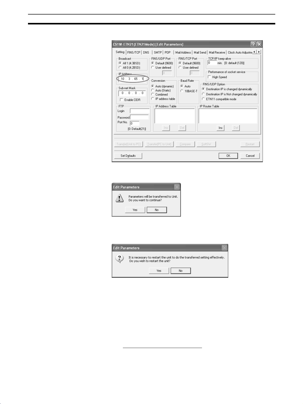
Unit Setup Procedure Section 2-7
5. Make the required settings (i.e., the IP address in this case).
6. Transfer the settings to the PLC.
Click on Yes in the following dialog box.
7. In order for the Ethernet Unit Setup to go into effect, the Unit must be restarted.
Click on Yes in the following dialog box.
8. Check the Ethernet Unit's LED indicators.
After the RUN indicator has turned OFF and then turned ON again, the
Ethernet will recognize the new settings (i.e., the IP address in this case).
2-7-2 Using the Web Browser Setting Function
For Ethernet Units with Unit Ver. 1.3 or later, the Ethernet Unit’s system settings can be set using the Web browser of a personal computer or other
device. The Ethernet Unit’s Web window is displayed by accessing the following URL from the Web browser.
URL: http://(Ethernet Unit’s IP address)/0
Use the following procedure to set the Unit’s system settings (IP address in
this example) using Internet Explorer version 6.0 and the Ethernet Unit’s Web
function.
43

Unit Setup Procedure Section 2-7
1,2,3... 1. Connect to the Ethernet Unit from the Web browser.
In this example, the URL is specified as http://192.168.250.1/0 using the
Ethernet Unit’s default IP address.
2. Select Settings from the menu on the left side of the window to display the
Settings Menu.
44

Unit Setup Procedure Section 2-7
3. Select 1. IP address and Protocols - System to display the Login Password field on the right of the window.
4. Input the default password (“ETHERNET” all in upper case) and click the
Login Button.
5. The settings in the System menu will be displayed.
The following window shows the default system settings.
45

Basic Settings Section 2-8
6. Make the required settings (i.e., the IP address in this example).
7. After entering the correct values, click the Set Button followed by the Reg-
ist Button to register them.
The Set Button is used to transfer the entered values from the personal computer, and temporarily register them in the Ethernet Unit.
The Regist Button stores the set values that have been temporarily registered
in the Ethernet to the flash memory (non-volatile memory) of the CPU Unit.
The Ethernet Unit reads the unit settings from flash memory (non-volatile
memory) when the power is turned ON or the Unit is restarted. Therefore,
when making the unit settings using the Web function, always click the Set
Button before the Regist Button. Otherwise the entered set values will not be
used. The Set Button and Regist Button are provided on the window for each
setting item.
The functions of the other buttons are as follows:
• Cancel Button
Use this button to cancel the entered value and display the value that was
previously set with the Set Button again. If the Set Button has not been
clicked, the value that was read from the CPU Unit’s flash memory (nonvolatile memory) when the Ethernet Unit was started will be displayed.
• Reload Button
Use this button read and display the values saved in the CPU Unit’s flash
memory (non-volatile memory).
8. To enable the unit settings that have been registered in the CPU Unit’s
flash memory (non-volatile memory, turn the power to the PLC OFF and
ON again, or restart the Ethernet Unit.
2-8 Basic Settings
The following items comprise the basic settings in the Ethernet Unit
(100Base-TX) setup. Each item is described in detail below.
■ IP Address
For the IP address, set the Ethernet Unit's local IP address.
46
• IP address
• Subnet mask
• Broadcast settings
• Baud rate
• TCP/IP keep-alive
•IP router table

Basic Settings Section 2-8
Depending on the value that is set, the IP address has a great influence on
the connectability of the Ethernet Unit. To make full use of the Ethernet functions, it is necessary to study the applications and network system design
when determining IP address allocations. Before setting the IP address, refer
to SECTION 5 Determining IP Addresses.
There are several ways to set IP addresses.
Default Setting
The Ethernet Unit operates using the default IP address when the Unit is
mounted to the PLC and initially registered in the I/O tables (i.e., when the
Unit settings have not been made and the IP Address Display/Setting in the
CPU Bus Unit Words Allocated in the DM Area is still all zeros).
The default IP address is determined as follows:
Default IP address = 192.168.250.FINS node address
The FINS node address is set by the rotary switch on the front of the Ethernet
Unit. If the defaults are used for the IP address and the Unit settings, the settings will be as shown below.
Item Operation status
IP address 192.168.250.FINS node address
Subnet mask 255.255.255.0 (Class C mask)
Broadcast settings 4.3BSD
Baud rate Auto
TCP/IP keep-alive 120 min.
IP router table None (IP router not enabled)
Setting the IP Address in the CPU Bus Unit Words Allocated in the DM
Area
This method sets the IP address in the IP Address Display/Setting Area in the
CPU Bus Unit Words Allocated in the DM Area, when the IP address is not set
in the Unit Setup. When the IP address is set in the Unit Setup, the IP Address
Display/Setting Area becomes the area for displaying the settings.
To make settings in the IP Address Display/Setting Area, use the CX-Programmer or Programming Console to write the values. In order for the new
settings to go into effect, either the Ethernet Unit must be restarted or the
power must be turned ON again to the PLC.
15 14 13 12 11 10 09 08 07 06 05 04 03 02 01 00
m+98 (1) (2) (3) (4)
m+99 (5) (6) (7) (8)
IP address: (1)(2).(3)(4).(5)(6).(7)(8) (hexadecimal)
If only the IP address is set, according to the IP Address Display/Setting Area,
and the defaults are used for all other Unit settings, the settings will be as
shown below.
Item Status
IP address Words allocated for CPU Bus Unit (m+98 to m+99)
Subnet mask Uses value corresponding to IP address class.
Broadcast settings 4.3BSD specifications
Baud rate Auto
TCP/IP keep-alive 120 minutes
IP router table Not set. (IP routing not supported.)
47

Basic Settings Section 2-8
Unit Setup
This method sets the IP address by first selecting the Ethernet Unit from the
CX-Programmer's I/O Table Window while connected online, and then setting
the IP address from the Unit Setup.
Example: Using the CX-Programmer to Set the IP Address to 10.3.65.1
When an IP address is set in the Unit Setup, that value is displayed in the IP
Address Display/Setting Area in the DM Area words allocated for CPU Bus
Units.
When the IP address is set by the CX-Programmer, and the defaults are used
for all other Unit settings, the settings will be as shown below.
Item Status
IP address Set by CX-Programmer.
Subnet mask Uses value corresponding to IP address class when
Broadcast settings 4.3BSD specifications
Baud rate Auto
TCP/IP keep-alive 120 minutes
IP router table Not set. (IP routing not supported.)
not using CIDR.
■ Subnet Mask
For the subnet mask, all bits corresponding to the bits in the IP address used
as either the net number or the subnet number are set to 1, and the bits corresponding to the host number are set to 0. These settings must be made when
using an address conversion method other than the IP address table method.
Starting from unit version 1.5, it is possible to use classless inter-domain routing by enabling CIDR. Enabling CIDR enables setting 192.0.0.0 to
255.255.255.252 for the subnet mask regardless of the IP address class.
48

Basic Settings Section 2-8
If CIDR is not enabled and a subnet mask is not set (i.e., the default of 0.0.0.0
is set) or an illegal value is set, one of the following values will be set as the
network mask according to the class of the local IP address.
Class Subnet mask
Class A 255.0.0.0
Class B 255.255.0.0
Class C 255.255.255.0
If classes are normally used, it is recommended to set a subnet mask values
corresponding to the class.
■ Broadcast Settings
Set the method for specifying IP addresses when broadcasting.
Setting Contents
All 1 (4.3BSD)
(Default)
All 0 (4.2BSD) Broadcast with Host ID all zeros (4.2BSD specifications).
■ Baud Rate
Set the baud rate.
Setting Contents
Auto (Default) Automatically detects the baud rate between hubs.
10Base-T Operates with 10Base-T (half duplex).
Broadcast with all ones for Host ID (4.3BSD specifications).
Operates with 100Base-TX (full duplex) whenever possible.
■ TCP/IP Keep-alive Setting
Set the Liveness-Checking Interval. (This setting is enabled only when
FINS/TCP or TCP/IP socket services are used.)
When the keep-alive function is used with FINS/TCP or TCP/IP socket services, the keep-alive communications frame is used to check the status of the
connection with the remote node (either a server or client) if there are no communications during the time interval set here. Up to nine checks are executed
at 75-second intervals. and if there is no response to any of them then the
connection is terminated.
The default setting (0) is for a specified value of 120 minutes for the LivenessChecking Interval. When the prescribed value is used as is, it may not be suitable for control system applications. Set the checking time as required for the
system. The setting range is 0 to 65,535 minutes.
■ IP Router Table
An IP router table is a table of correspondences for finding IP addresses for
the IP routers that relay target segments when the Unit communicates via IP
routers with nodes on other IP network segments.
130.26.X.X (Network ID)130.25.X.X (Network ID)
130.25.36.253 130.26.2.254
IP router
Node BNode A
49

Unit Setup for Particular Applications Section 2-9
For the IP network address, set the network number (i.e., the net ID) of the
other IP network segment with which communications are to be executed.
The length of the network number (i.e., the number of bytes) will vary depending on the IP address class. Four bytes are reserved for setting the IP network
address, so set the network number from the beginning and then set 00 in the
remaining space.
A maximum of eight settings can be registered. The default is for nothing to be
set.
Settings
In this example setting for Node A (refer to the diagram above), a node with an
IP address of 130.26.1.1 is connected to an IP router with an IP address of
130.25.36.253.
Only one default IP router can be set.
The default IP router is selected when no Network ID exists in the IP router
table for the destination network number. To set the default IP router, set
0.0.0.0 for the IP address and set the default IP router's IP address for the
router address.
2-9 Unit Setup for Particular Applications
Aside from the basic settings, the required settings vary depending on the
particular communications applications that are used.
For details on settings, refer to SECTION 3 CX-Programmer Unit Setup.
FINS/UDP
CX-Programmer tab Settings
Setup Conversion
FINS/UDP Port No.
IP Address Table
Destination IP Address
Change Dynamically
For details, refer to SECTION 6 FINS Communications Service in the Opera-
tion Manual Construction of Networks.
Use CX-Integrator to make routing table settings as required.
FINS/TCP
50
CX-Programmer tab Settings
Setup FINS/TCP Port No.
FINS/TCP FINS/TCP Connection Setup
For details, refer to SECTION 6 FINS Communications Service in the Opera-
tion Manual Construction of Networks.

Unit Setup for Particular Applications Section 2-9
Use CX-Integrator to make routing table settings as required.
Socket Services
CX-Programmer tab Setting
Setup Keep-alive
FTP
CX-Programmer tab Settings
Setup Login
Password
Port No
For details, refer to SECTION 4 FTP Server Function in the Operation Manual
Construction of Applications.
Mail
CX-Programmer tab Settings
DNS IP Address
Por t No.
Retry timer
SMTP Server specification type
IP Address
Host name
Por t No.
Local mail address
Use POP before SMTP
Mail Address Mail address 1
Mail address 2
Send Mail Transmission trigger setting
Trigger classification
Interval time
Mail address
Transmission data classification
Mail Reception
For details, refer to SECTION 2 Mail Send Function in the Operation Manual
Construction of Applications.
CX-Programmer tab Settings
DNS IP Address
Por t No.
Retry timer
POP Server specification type
IP Address
Host name
Por t No.
Account Name
Mail password
Server access interval time
51

Communications Test Section 2-10
CX-Programmer tab Settings
Receive Mail Posting Mail Address Protection Setting
Receive Attached File Setting
Receive Command Setting
For details, refer to SECTION 3 Mail Receive Function in the Operation Man-
ual Construction of Applications.
Automatic Clock Adjustment
CX-Programmer tab Settings
DNS IP Address
Por t No.
Retry timer
Auto Adjust Time SNTP Server Setup
Auto Adjust Time
Server specification type
IP Address
Host name
Por t No.
Retry timer
Adjust Time
For details, refer to SECTION 5 Automatic Clock Adjustment Function in the
Operation Manual Construction of Applications.
Web Functions
CX-Programmer
tab
HTTP Use Web function
For details, refer to Appendix G Ethernet Unit Web Function.
2-10 Communications Test
If the basic settings (in particular the IP address and subnet mask) have been
made correctly for the Ethernet Unit, then it should be possible to communicate with nodes on the Ethernet.
This section describes how to use the PING command to perform communications testing between Ethernet Units.
2-10-1 PING Command
The PING command sends an echo request packet to a remote node and
receives an echo response packet to confirm that the remote node is communicating correctly. The PING command uses the ICMP echo request and
responses. The echo response packet is automatically returned by the ICMP.
The PING command is normally used to check the connections of remote
nodes when configuring a network. The Ethernet Unit supports both the ICMP
echo request and reply functions.
Setting item
Password
Port No.
52

Communications Test Section 2-10
If the remote node returns a normal response to the PING command, then the
nodes are physically connected correctly and Ethernet node settings are correct.
2-10-2 Ethernet Unit
2-10-3 Host Computer
PLC
Ethernet Unit
Echo request
Echo response
Remote Node
(host computer or Ethernet Unit)
TCP UDP
ICMP
Ethernet
IP
The Ethernet Unit automatically returns the echo response packet in
response to an echo request packet sent by another node (host computer or
other Ethernet Unit). An echo request packet can be sent to another node by
issuing the FINS command to execute the PING command from the PLC.
Refer to page 184 for details on the PING command.
The PING command can be executed from the host computer to send an
echo request packet to an Ethernet Unit. The method for using the PING command from a UNIX computer is given next.
Method
Note The PING command is not supported by some host computers.
Application Examples
Normal Execution $
Input the following at the host computer prompt ($):
$ ping IP_address(host_name)
The destination is specified by its IP address or host name. If the host name is
used, the host name must be defined in file /etc/hosts.
These examples show sending the PING command to the node at IP address
130.25.36.8. The “$” in the example represents the host computer prompt.
User inputs are underlined. Comments are placed after semicolons.
ping 130.25.36.8 ; Executes PING command
PING 130.25.36.8: 56 data bytes
64 bytes from 130.25.36.8: icmp_seq=0. time=0.ms
64 bytes from 130.25.36.8: icmp_seq=0. time=0.ms
...
...
...
64 bytes from 130.25.36.8: icmp_seq=0. time=0.ms
←Enter Ctrl+C Key to cancel.
––––130.25.36.8 PING Statistics––––
9 packets transmitted, 9 packets received, 0% packets loss
round–trip (ms) min/avg/max = 0/1/16
$
53

Converting from Previous Models Section 2-11
Abnormal Execution $ ping 130.25.36.8 ; Executes PING command
PING 130.25.36.8: 56 data bytes
←Enter Ctrl+C Key to cancel.
––––130.25.36.8 PING Statistics––––
9 packets transmitted, 0 packets received, 100% packets loss
$
Refer to operating system documentation for your host computer for details
about using the host computer’s PING command.
2-11 Converting from Previous Models
The specifications for these Ethernet Units (CS1W-ETN21 and CJ1W-ETN21)
are compatible with those for previous models (CS1W-ETN01/ETN11 and
CJ1W-ETN11), so previous models being used with existing equipment can
be easily replaced by the new models. Many of the specifications for the new
Ethernet Units have been expanded, however, so there will be a number of
limitations if the Unit is simply replaced.
In particular, the CPU Bus Unit System Setup Area is formatted for the previous models, so there is no way to make the settings for the expanded specifications.
To remove these limitations, it is necessary to change the CPU Bus Unit System Setup format from “ETN11 mode” to “ETN21 mode.” Refer to Changing
the CPU Bus Unit System Setup Area Format below for instructions on how to
make the change.
If the format change is from ETN11 mode to ETN21 mode, then there will be
no effect on previous applications. If the change is from ETN21 mode to
ETN11 mode, however, then certain limitations will go into effect.
The following table shows the limitations that apply when operating in ETN11
mode.
Item Specifications in ETN11 mode
Baud rate • Automatic detection (100Base-TX or
10Base-T)
Subnet mask • CIDR is not used.
• Operation is performed with the default network mask if the subnet mask specification is
less than the network mask for each class.
FINS node address setting range • 1 to 254
IP address conversion: Automatic
generation method
TCP keep-alive • No time setting (Uses default setting)
FINS/TCP • Server only for all connections (Uses default
TCP socket services • Socket option (keep-alive setting): Yes
FTP server function • Port No. setting: No (Uses default setting)
• Dynamic only
setting)
• Number of Bytes Received at TCP Socket
Nos. 1 to 8: Yes
• Data Received Flag: Yes
• Socket high-speed option: No
54

Converting from Previous Models Section 2-11
Item Specifications in ETN11 mode
Mail send function • The specifications for previous Units apply.
• The mail transmission status is as follows:
• Status of user mail transmission → Status
of transmission condition setting 5
• Status of periodic mail transmission → Sta-
tus of transmission condition setting 6
• Status of mail transmission when error
occurs → Status of transmission condition
setting 7
Mail receive function • Cannot be used
Automatic clock adjustment function • Cannot be used
DNS server host name • Cannot be used
Note (1) These limitations do not apply when the CPU Bus Unit System Setup
Area format is in ETN21 mode.
(2) When I/O tables are created using one of the new Ethernet Unit models,
the CPU Bus Unit System Setup Area format is in ETN21 mode from the
beginning.
Checking the CPU Bus Unit System Setup Area Format
Checking with the CX-Programmer's Software Switch Monitor - Status Tab Page
55
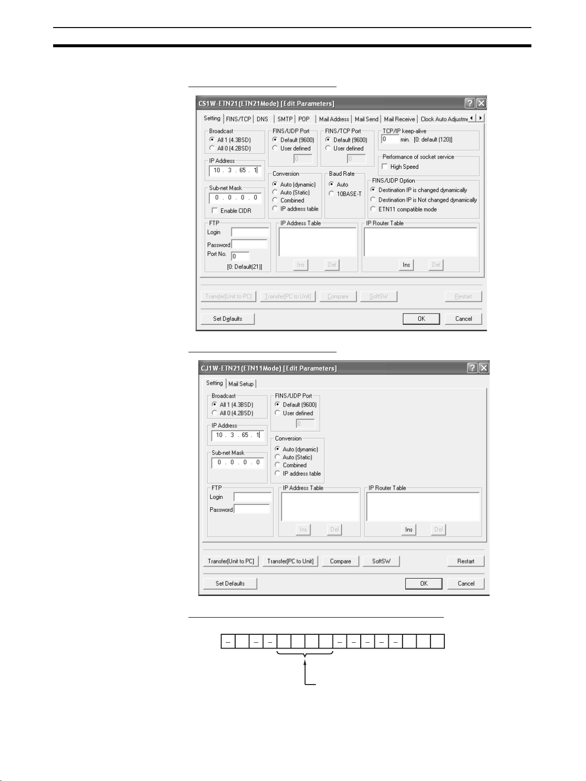
Converting from Previous Models Section 2-11
Checking with the CX-Programmer's Unit Setup Window
■ Window Display in ETN21 Mode
■ Window Display in ETN11 Mode
■ Checking by Reading Words Allocated in the CIO Area
15 14 13 12 11 10 09 08 07 06 05 04 03 02 01 00
n+17
56
System Setting Format

Converting from Previous Models Section 2-11
Bit address Format classification
11 10 09 08
0000ETN11 mode
0001ETN21 mode
Other Reserved
Changing the CPU Bus
Unit System Setup Area
Format
The CPU Bus Unit System Setup Area format can be changed in either of the
following two ways. Select the method that can be used in the system in which
the Unit is to be replaced.
• By means of the CX-Programmer's Unit Setup
• By manipulating the rotary switches for the node address with a precision
screwdriver
■ Using the
Change ETN21 Mode Command from the Options Menu in the
I/O Table Window of the CX-Programmer
1. Select Change ETN21 Mode from the Options Menu in the I/O Table Window.
2. The following confirmation message will be displayed. To change the
mode, click Yes.
3. After the mode has been changed, the following confirmation message will
be displayed. Click OK to restart the Ethernet Unit.
After the Unit has been restarted, it will begin to operate in ETN21 mode.
57

Converting from Previous Models Section 2-11
■ Manipulating the Rotary Switches for the Node Address with a Precision
Screwdriver
Converting from ETN11 Mode to ETN21 Mode
1. Turn OFF the power to the PLC, and set the Ethernet Unit's rotary switches
for the node address as follows:
Node address Indicators
1
×16
0 0 Not lit Not lit Not lit
2. Turn ON the power to the PLC. The Unit's indicators will change as follows:
Node address Indicators
1
×16
0 0 Not lit Lit Not lit
×6
×16
0
0
RUN ERC ERH
RUN ERC ERH
3. Set the rotary switches for the node address to 01. There will be no change
to the indicators.
Node address Indicators
1
×6
0 1 Not lit Lit Not lit
×16
0
RUN ERC ERH
4. Set the rotary switches for the node address to F1. The RUN indicator will
begin to flash.
Node address Indicators
1
×16
F 1 Flashing Lit Not lit
×16
0
RUN ERC ERH
5. Set the rotary switches for the node address to 01. The Unit mode change
function will start, and the ERH indicator will flash for approximately five
seconds.
Node address Indicators
1
×16
0 1 Flashing Lit Flashing
×16
0
RUN ERC ERH
6. After the mode has been changed, the indicators will appear as shown below, depending on whether the change was completed normally or if an error occurred.
• If the Mode Change was Completed Normally
Node address Indicators
1
×16
0 1 Flashing Lit Lit
×16
0
RUN ERC ERH
58

Converting from Previous Models Section 2-11
• If an Error Occurred in the Mode Change
Node address Indicators
1
×16
0 1 Flashing Lit Not lit
Note If an error occurs in the mode change, remove the Ethernet Unit,
create the I/O tables, and correct the settings using the procedures
described in this section.
7. Turn OFF the power to the PLC and return the Ethernet Unit's rotary
switches for the node address to its original setting.
8. Turn ON the power to the PLC.
Node address Indicators
1
×16
- - Lit Not lit Not lit
×16
×16
0
0
RUN ERC ERH
RUN ERC ERH
Converting from
ETN21 Mode to ETN11 Mode
1. Turn OFF the power to the PLC, and set the Ethernet Unit's rotary switches
for the node address as follows:
Node address Indicators
1
×16
0 0 Not lit Not lit Not lit
×16
0
RUN ERC ERH
2. Turn ON the power to the PLC. The Unit's indicators will change as follows:
Node address Indicators
1
×16
0 0 Not lit Lit Not lit
×16
0
RUN ERC ERH
3. Set the rotary switches for the node address to 0F. There will be no change
to the indicators.
Node address Indicators
1
×16
0 F Not lit Lit Not lit
×16
0
RUN ERC ERH
4. Set the rotary switches for the node address to FF. The RUN indicator will
begin to flash.
Node address Indicators
1
×16
F F Flashing Lit Not lit
×16
0
RUN ERC ERH
5. Set the rotary switches for the node address to 0F. The Unit mode change
function will start, and the ERH indicator will flash for approximately five
seconds.
Node address Indicators
1
×16
0 F Flashing Lit Flashing
×16
0
RUN ERC ERH
6. After the mode has been changed, the indicators will appear as shown below, depending on whether the change was completed normally or if an error occurred.
59

Converting from Previous Models Section 2-11
• If the Mode Change was Completed Normally
Node address Indicators
1
×16
0 F Flashing Lit Lit
• If an Error Occurred in the Mode Change
Node address Indicators
1
×16
0 F Flashing Lit Not lit
Note If an error occurs in the mode change, remove the Ethernet Unit,
create the I/O tables, and correct the settings using the procedures
described in this section.
7. Turn OFF the power to the PLC and return the Ethernet Unit's rotary
switches for the node address to its original setting.
8. Turn ON the power to the PLC.
Node address Indicators
1
×16
- - Lit Not lit Not lit
×16
×16
×16
0
0
0
RUN ERC ERH
RUN ERC ERH
RUN ERC ERH
60

SECTION 3
CX-Programmer Unit Setup
This section describes how to install the Ethernet Unit and make the initial settings required for operation.
3-1 Setup . . . . . . . . . . . . . . . . . . . . . . . . . . . . . . . . . . . . . . . . . . . . . . . . . . . . . . . . 62
3-2 FINS/TCP . . . . . . . . . . . . . . . . . . . . . . . . . . . . . . . . . . . . . . . . . . . . . . . . . . . . 64
3-3 DNS. . . . . . . . . . . . . . . . . . . . . . . . . . . . . . . . . . . . . . . . . . . . . . . . . . . . . . . . . 66
3-4 SMTP . . . . . . . . . . . . . . . . . . . . . . . . . . . . . . . . . . . . . . . . . . . . . . . . . . . . . . . 67
3-5 POP . . . . . . . . . . . . . . . . . . . . . . . . . . . . . . . . . . . . . . . . . . . . . . . . . . . . . . . . . 68
3-6 Mail Address . . . . . . . . . . . . . . . . . . . . . . . . . . . . . . . . . . . . . . . . . . . . . . . . . . 69
3-7 Send Mail . . . . . . . . . . . . . . . . . . . . . . . . . . . . . . . . . . . . . . . . . . . . . . . . . . . . 70
3-8 Receive Mail . . . . . . . . . . . . . . . . . . . . . . . . . . . . . . . . . . . . . . . . . . . . . . . . . . 72
3-9 Auto Adjust Time . . . . . . . . . . . . . . . . . . . . . . . . . . . . . . . . . . . . . . . . . . . . . . 74
3-10 HTTP. . . . . . . . . . . . . . . . . . . . . . . . . . . . . . . . . . . . . . . . . . . . . . . . . . . . . . . . 75
61

Setup Section 3-1
3-1 Setup
Item Contents Default
Broadcast Set the method for specifying IP addresses for broadcasting in FINS/
UDP.
• All 1 (4.3BSD): Broadcast with host number set to all ones.
• All 0 (4.2BSD): Broadcast with host number set to all zeros.
Normally the default setting should be used.
IP Address Set the local IP address for the Ethernet Unit. 0.0.0.0 (FINS node
Sub-net Mask Set the subnet mask for the Ethernet Unit.
This is required if a method other than the IP address table method is
used for address conversion.
Enable CIDR Set the specifications for the subnet mask.
• Disabled: Set for the range of class A, class B, and class C.
• Enabled: Classless setting range (192.0.0.0 to 255.255.255.252)
FINS/UDP Port Specify the local UDP port number to be used for the FINS communica-
tions service. The UDP port number is the number used for UDP identification of the application layer (i.e., the FINS communications service in
this case).
• Default (9,600)
• User defined (Setting range: 1 to 65,535)
Note: Make the settings so that UDP port number 123 for SNTP does
not overlap with UDP port number 53 for DNS.
FINS/TCP Port Specify the local TCP port number to be used for the FINS communica-
tions service. The TCP port number is the number used for TCP identification of the application layer (i.e., the FINS communications service in
this case).
• Default (9,600)
• User defined (Setting range: 1 to 65,535)
Note: Make the settings so that TCP port numbers 20 and 21 for the
FTP server, TCP port number 25 for SMTP, TCP port number 110 for
POP3, and TCP port number 53 for DNS do not overlap.
All 1 (4.3BSD)
address
192.168.250.)
0.0.0.0
(default subnet
mask for IP address
setting)
Disabled
9,600
9,600
62

Setup Section 3-1
Item Contents Default
Conversion Select any of the following as the method for finding and converting IP
Destination IP Address
(Change Dynamically)
Baud Rate Select the Ethernet baud rate for the Ethernet Unit.
TCP/IP keep-alive Set the liveness-checking interval. When socket services using either
IP Address Table Set the IP address table that defines the relationship between FINS
IP Router Table Set when the Ethernet Unit is to communicate through the IP router with
FTP Login Sets the login name for connecting to the Ethernet Unit by FTP. None
Password Sets the password for connecting to the Ethernet Unit by FTP. None
Port No. Set the FTP port number for the Ethernet Unit.
High-speed Socket Services
addresses from FINS node addresses. (Enabled for FINS/UDP only.)
• Automatic generation (dynamic): Auto (dynamic)
• Automatic generation (static): Auto (Static)
• IP address table method: Table used
• Combined method: Mixed
Select to dynamically change the remote (destination) IP address for
FINS/UDP. To prohibit dynamic changes, deselect this box.
Select either automatic detection or 10Base-T. (For 100Base-TX, select
automatic detection.)
FINS/TCP or TCP/IP are used, the connection will be terminated if there
is no response from the remote node (either a server or client) within the
time set here. (Enabled for socket services using FINS/TCP or TCP/IP
only.)
Setting range: 0 to 65,535 minutes
This setting applies to the keep-alive setting for each connection set
with the FINS/TCP tab.
node addresses and IP addresses.
With FINS/UDP, this is enabled only when the IP address table method
is set as the IP address conversion method.
nodes on another IP network segment.
There is normally no need to change this number.
Two ports are used for FTP: a control port and a data transfer port. This
setting sets only the control port, and then the data transfer port uses
the number that is one less than the control port.
Selecting this option improves the performance of processing for sending and receiving using specific bits for socket services. For information
on communications performance, refer to 6-9-5 Times Required for
Sending and Receiving for Socket Services in the Ethernet Units Construction of Applications Operation Manual. When the High Speed
Option is selected, socket services that are implemented using a
CMND(490) instruction will cause an error.
Auto (dynamic)
Checked
(Change Dynamically)
Auto
0
(120 minutes)
None
None
(“CONFIDENTIAL”)
0
(Number 21 is
used.)
Disabled
Note (1) The setting to enable or disable dynamic changing of remote IP address-
es is available for Ethernet Units with Unit Ver. 1.3 or later.
(2) Make settings using the unit settings function in the CX-Programmer (to
be included in version 5.0 and higher) or using the Web function (refer to
Appendix G Ethernet Unit Web Function).
(3) The Enable CIDR Option and High Speed Option for performance of
socket service are supported starting with unit version 1.5.
63

FINS/TCP Section 3-2
3-2 FINS/TCP
FINS/TCP Connection Setup
No. Shows the connection number. This is a network API
Use IP address
to protect
Item Contents Default
used when TCP is used for the FINS communications service. It corresponds to a socket in the socket
services. Up to 16 can be used at a time, and they
are identified by connection numbers 1 to 16. The
Ethernet Unit can thus simultaneously execute the
FINS communications service by TCP with up to 16
remote nodes.
When this option is selected, if the Ethernet Unit is
set for use as a server, and if a connection number
other than 0.0.0.0 is set for a destination IP address,
any connection request from other than the number
set for that IP address will be denied.
Select this option to prevent faulty operation (by
FINS commands) from specific nodes from affecting
the PLC.
Not protected
64

FINS/TCP Section 3-2
The following settings can be made for each connection number.
Item Contents Default
FINS/TCP Mode For each connection number, this setting specifies
IP Address • When the Ethernet Unit is used as a server:
Auto allocated
FINS node
keep-alive For each connection number, set whether or not the
the Ethernet Unit for use as either a server or a client.
• When the Ethernet Unit is used as a server:
The Ethernet Unit opens a connection with that
connection number and waits for service requests
(FINS commands) from clients. Connection numbers are used in ascending order and allocated to
clients in the order connections are made.
• When the Ethernet Unit is used as a client:
The Ethernet Unit establishes a connection with
the server set as the destination IP address. Once
the connection has been established, FINS/TCP is
used for FINS communications.
If the option is selected to use IP addresses to protect, set the IP addresses as required at clients
from which connection is permitted. If not set for
those connections, the default setting of 0.0.0.0
can be used.
• When the Ethernet Unit is used as a client:
Set the IP address for the remote Ethernet Unit
(i.e., the server) that is to be connected by FINS/
TCP. It is required that an IP address be set for the
remote Ethernet Unit.
If the client (normally a personal computer) application supports FINS/TCP, and if FINS node
addresses are not fixed, the client will take 0 as its
node address. Then, when a FINS command
arrives, the number set here (from 239 to 254) will
automatically be allocated as the client's FINS node
address.
For details on automatic allocation of FINS node
addresses, refer to the Operation Manual Construc-
tion of Applications.
remote node connection check function is to be
used for the FINS/TCP server and client.
If the keep-alive box is checked here, then, when
the remote node goes without responding for longer
than the monitor time set in the Setup, the connection will be terminated. If a remote node turns OFF
without warning, the connection will remain open
indefinitely, so this option should be used whenever
possible.
Server
0.0.0.0
From 239 to
254, for connection Nos.
1 to 16
Use
For details, refer to SECTION 6 FINS Communications Service in the Opera-
tion Manual Construction of Networks.
65

DNS Section 3-3
3-3 DNS
DNS Server Setup
Item Contents Default
IP Address Set the IP address for the DNS server.
The DNS server is required when specifying the POP3,
SMTP, or SNTP servers by host name for the mail send
function or mail receive function.
Port No. Set the port to be used for connecting to the DNS
server.
This setting does not normally need to be changed.
Retry Timer Set the time to elapse before retrying when a connec-
tion to the DNS server fails.
This setting does not normally need to be changed.
None
0
(Number 53 is
used.)
0 (10 s)
66

SMTP Section 3-4
3-4 SMTP
SMTP Server Setup
Item Contents Default
Designation
Method
IP Address Set the IP address for the SMTP server used for
Host Name Set the host domain name (i.e., the host name)
Port No. Set the port to be used for connecting to the
Local Mail
Address
Use POP before
SMTP
Select whether the SMTP server used for sending mail is to be specified by IP address or the
host's domain name (i.e., host name).
sending mail.
This setting is enabled only when “IP address” is
selected as the method for specifying the server.
for the SMTP server that is to be used for sending mail.
This setting is enabled only when “host name” is
selected as the method for specifying the server.
SMTP server that is to be used for sending mail.
This setting does not normally need to be
changed.
Set the mail address for the Ethernet Unit. None
Select whether or not to use the mail receiving
method (POP before SMTP) in which the POP
server must be accessed (to receive mail) before
the SMTP server is accessed (to send mail).
IP Address
0.0.0.0
None
0
(No. 25 is used.)
Not checked
For details, refer to SECTION 2 Mail Send Function in the Operation Manual
Construction of Applications.
67

POP Section 3-5
3-5 POP
POP Server Setup
Item Contents Default
Designation
Method
IP Address Set the IP address for the POP3 server used for
Host Name Set the host domain name (i.e., the host name) for
Port No. Set the port to be used for connecting to the POP3
Account Name Set the account name to be used for sending and
Mail Password Set a password for the account that is to be used
Server Access
Interval
Select whether the POP3 server used for receiving
mail is to be specified by IP address or the host's
domain name (i.e., host name).
receiving mail.
This setting is enabled only when “IP address” is
selected as the method for specifying the server.
the POP3 server that is to be used for receiving
mail.
This setting is enabled only when “host name” is
selected as the method for specifying the server.
server that is to be used for receiving mail.
This setting does not normally need to be changed.
receiving mail.
Only alphanumeric characters can be used.
If no account name is set, the portion of the local e-
mail address to the left of the @ will be used.
for sending and receiving mail.
Set the interval for sending and receiving mail. Mail
will be automatically sent and received at the interval set here.
IP Address
0.0.0.0
None
0
(Number 110
is used.)
None
None
0
(5 minutes)
68
For details, refer to SECTION 3 Mail Receive Function in the Operation Manual Construction of Applications.

Mail Address Section 3-6
3-6 Mail Address
Destination Mail Address Setup
Item Contents Default
Mail Address 1 Set one of the addresses to which the Ethernet Unit
Mail Address 2 Set one of the addresses to which the Ethernet Unit
For details, refer to SECTION 2 Mail Send Function in the Operation Manual
Construction of Applications.
None
is to send mail. (Up to two address can be set.)
Note: Mail can be sent to multiple addresses by
punctuating the mail address with commas.
None
is to send mail. (Up to two address can be set.)
Note: Mail can be sent to multiple addresses by
punctuating the mail address with commas.
69

Send Mail Section 3-7
3-7 Send Mail
Item Contents Default
Send Trigger Select a number as the trigger condition for send-
ing mail. Up to eight trigger numbers can be registered.
Use send trigger Sets whether or not the selected mail trigger is to
be enabled.
---
Not checked
70

Send Mail Section 3-7
Item Contents Default
Mail
trigger
type
(Select
only
one.)
Mail address Select the destination mail address.
Send user data If this option is selected, user-created data is sent
Send Error Log
information
Send status information
Send file data/I/O
memory data
Attached file
name
Software
switch
Word
value
change
Bit value
change
ETN
condition
CPU
condition
Interval
time
(Periodic
timer)
If this option is selected, mail is sent whenever the
Mail Send Switch turns ON.
The Mail Send Switch is bit 03 of word n in the
words allocated for CPU Bus Units. (n = 1500 + 25
x unit number)
If this option is selected, the value of a specified
address is compared with a standard comparison
value using one of the following comparison functions, and mail is sent whenever the condition is
satisfied.
=, <>, <, <=, >=, >
Select the address for storing the comparison
value from the drop-down list.
If this option is selected, mail is sent whenever a
specified bit turns ON or whenever it turns OFF.
Select the bit address from the drop-down list
below.
If this option is selected, mail is sent whenever a
new error is stored in the Ethernet Unit's error log.
If this option is selected, mail is sent whenever any
of the following conditions occur at the CPU Unit.
The drop-down list at the right can be used to
select which of these three are to serve as mail
triggers.
• When a non-fatal error occurs
• When a fatal error occurs
• When the operating mode is changed
If this option is selected, mail is sent at fixed time
intervals.
The time interval (in minutes) can be set in the
interval time box.
The mail destination is the one set under the Mail
Address tab.
in the body of the mail.
The location for storing the user-created data is
set by the user-defined mail address setting
below.
If this option is selected, the error log is included in
the body of the mail.
If this option is selected, status information is
included in the body of the mail.
If this option is selected, any of the following types
of data can be sent as file attachments to e-mail.
• I/O memory data (.IOM)
• I/O memory data (.TXT)
• I/O memory data (.CSV)
• File data (any file)
Select the type of data to be attached from the
checkboxes below. If I/O memory data is selected,
then also select, in “I/O memory data” below, the
address and range of data to be sent.
If the above setting is checked so that files can be
sent as attachments, then specify the name of the
file that is to be sent.
Checked
Not checked
Not checked
Not checked
Not checked
Not checked
Address 1
Not checked
Not checked
Not checked
Not checked
None
71

Receive Mail Section 3-8
Item Contents Default
Interval time When “Periodic
timer” is set as
the mail trigger
type
When “Bit value
change” or
“Word value
change” is set
as the mail trigger type
Set the time interval for sending
mail.
1 to 1,440 (10 to 14,400 min), in
units of 10 min
Set the time interval for monitoring the value at a specified
address.
1 to 1,000 (1 to 1,000 s), in units
of 1 s
Default: 0000
0
(10 minutes)
0
(1 second)
For details, refer to SECTION 2 Mail Send Function in the Operation Manual
Construction of Applications.
3-8 Receive Mail
Posting Mail Address Protection Setting
Item Contents Default
Protect by mail
address
Source mail Set the mail address if the option has been
72
If this option is selected, mail from sources
other than specified addresses is denied.
Use the “Mail address” text box below to specify the sources from which to receive mail.
checked to protect using mail address.
Mail will not be accepted from sources other
than the mail address set here.
Not checked
None

Receive Mail Section 3-8
Receive Attached File Setting
Item Contents Default
Receive a specified
extension file only
OBJ If this option is selected, an OBJ file (which can
STD If this option is selected, an STD file containing
IOM If this option is selected, an IOM file containing
CSV If this option is selected, CSV files (created by
TXT If this option is selected, text files can be
Custom 1 to 3 If this option is selected, files with extensions
If this option is selected, only file attachments
with specified extensions is accepted with mail.
Use the checkboxes below to select which file
extensions are to be accepted. Multiple extensions can be selected.
be created using the CX-Programmer) containing all cyclic task and interrupt task programs in
the CPU Unit will be received.
the PLC Setup, registered I/O tables, routing
tables, Unit Setups, etc. (which can be read
from the CPU Unit using the CX-Programmer)
will be received.
bit data from beginning to end of a memory
area (which can be created using the CX-Programmer) will be received.
programs such as Excel) can be received.
received.
specified by the user can be received.
Not
checked
Checked
Receive Command Setting
Item Contents Default
Receive a specified command only
FileWrite If checked, files can be written. Not checked
FileRead If checked, files can be read. Checked
FileDelete If checked, files can be deleted. Not checked
FileList If checked, files can be listed. Checked
UMBackup If checked, the user program can be
PARAMBackup If checked, the parameter area can be
IOMWrite If checked, writing to the I/O memory
IOMRead If checked, the I/O memory area can be
ChangeMode If checked, the operating mode can be
ErrorLogRead If checked, the error log can be read. Checked
ErrorLogClear If checked, the error log can be cleared. Checked
MailLogRead If checked, the mail log can be read. Checked
MailLogClear If checked, the mail log can be cleared. Checked
Test If checked, the mail receive test can be
FinsSend If checked, FINS commands can be
If this option is selected, only specified
remote mail commands are executed.
The commands to be received can be
specified in the checkboxes below.
backed up.
backed up.
area is permitted.
read.
changed.
executed.
executed.
Checked
Checked
Checked
Not checked
Checked
Not checked
Checked
Not checked
73

Auto Adjust Time Section 3-9
For details, refer to SECTION 3 Mail Receive Function in the Operation Manual Construction of Applications.
3-9 Auto Adjust Time
SNTP Server Setup
Item Contents Default
Obtain clock
data from SNTP
server
Auto Adjustment Set the time at which the SNTP server is to be
Designation
Method
IP Address Set the IP address for the SNTP server that is to be
Host Name Set the host domain name (i.e., the host name) for
Port No. Set the port number for connecting to the SNTP
If this option is selected, the CPU Unit's clock is set to
the time at the SNTP server's clock.
The clock can be changed only for the CPU Unit to
which the Ethernet Unit is mounted.
accessed to synchronize the clocks.
When the time that is set here arrives, the SNTP
server is accessed and the CPU Unit clock is
adjusted to match the SNTP server clock.
Select whether the SNTP server used for automatic
clock adjustment is to be specified by IP address or
by host domain name (i.e., by host name).
used for automatic clock adjustment.
This setting is enabled only when server specification
by IP address has been selected.
the SNTP server that is to be used for automatic
clock adjustment.
This setting is enabled only when server specification
by host name has been selected.
server that is to be used for automatic clock adjustment. This setting does not normally need to be
changed.
Not
checked
0:0:0
IP Address
0.0.0.0
None
0
(Number
123 is
used.)
74

HTTP Section 3-10
Item Contents Default
Retry Timer Set the time to elapse before retrying when a connec-
Time Lag
Adjustment
tion to the SNTP server fails. This setting does not
normally need to be changed.
This sets in the CPU Unit's clock data the time difference made up from the SNTP server's clock data.
To use the clock data from the SNTP server just as it
is, input 0.
0
(10 s)
+0:0
For details, refer to SECTION 5 Automatic Clock Adjustment Function in the
Operation Manual Construction of Applications.
3-10 HTTP
HTTP Server Setup
Item Contents Default
Use WEB functions
Password Sets the password for accessing
Port No. Sets the port No. used to connect to
Select to use or prohibit the Web
function. Deselect this option to prohibit use of the Web function.
the Ethernet Unit’s settings and status monitoring information using a
Web browser.
the Web browser.
Checked (Web function is used.)
None
(“ETHERNET” is used.)
0 (80 is used.)
For details, refer to Appendix G Ethernet Unit Web Function.
Note (1) The HTTP Server Setup is supported by Ethernet Units with Unit Ver. 1.3
or later.
(2) Make settings using the unit settings function in the CX-Programmer (to
be included in version 5.0 and higher) or using the Web function (refer to
Appendix G Ethernet Unit Web Function).
75
 Loading...