

Omron CS1W-DRM21-V1 Instruction
CS-series DeviceNet Unit
CS1W-DRM21-V1
Improve Maintenance
• Operation time monitor function
• Contact operations counter (See note.)
• Unit conduction time monitor function
• Total ON time monitor function (See note.)
•
Network power supply voltage monitor function
• Communications error log function
• Last maintenance date
• Comparator function
• Selectable output value after error
Reduce Downtime
•
Unit comments function
• Connected device comments function
• I/O power supply monitor function
• Sensor power supply short-circuit detection function
• External load short-circuit detection function
• Disconnected sensor detection function
Reduce Setup Time
• Network power supply monitor function
• Input filter function
• Power-ON inrush current
protection function
• Communications speed
auto-detect function
• Scaling function
• User compensation function
• Cumulative counter
• Moving average processing function
• Number of A/D conversion points
(conversion cycle) setting
• Peak/bottom hold function
• Top/valley hold function
• Percentage change calculation
function
Maintenance systemControl system
DeviceNet
Configurator
Ethernet
Maintenance information
PLC
Control
information
DRT2-series
Smart Slave
Remote I/O Terminals
DRT2-series
Smart Slave
Analog I/O Terminals
DRT2-series
Smart Slave
Environment-resistive
Terminals
DRT2-series
Smart Slave
Sensor Terminals
E5ZN-DRT
Smart Slave DeviceNet
Communications Unit
Network power supply voltage monitor
Unit/Connected device comments
Unit power-ON time monitor
Common Smart Slave Functions
DRT2-series
Screw-less Clamp
Terminals
DRT2-series
Remote I/O Terminals
Relay Output Terminals
DRT2-series
Remote I/O Terminals
Models with 3-tier
Terminal Blocks
DRT2-series
MIL Connector
Terminals
Smart Slave:
DRT2-series
Board Terminals
with MIL Connectors
CS1W-DRM21-V1
CSM_CS1W-DRM21-V1_DS_E_5_3
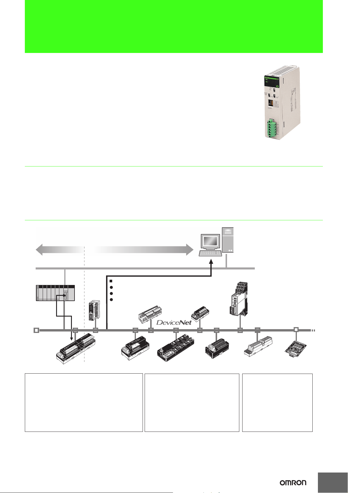
A DeviceNet Unit for the CS Series
That Boasts Industry-leading
Performance and Functions
Features
• Allows control of up to 32,000 points (2,000 words) per master, and ensures a high degree of simultaneity between data.
• Can be used as both a master and a slave at the same time.
• Equipped with settings and monitor functions aimed at improving both design and startup efficiency. Achieve maximum performance by using
in combination with a Configurator.
• Files of master and slave settings can be uploaded and downloaded using memory cards, allowing effective debugging and easier setup.
System Configurations
Note: The number of contact operations monitor function and the cumulative ON time monitor function cannot be used simultaneously for the same
contact.
1
CS1W-DRM21-V1
Device
Device
Device
Device
Device
Device
Device Device
Device
DeviceDevice
Terminating
resistance
Terminating
resistance
Tap Tap Tap
Tap
24 V DC power supply
for network
Tap
Device
Tap
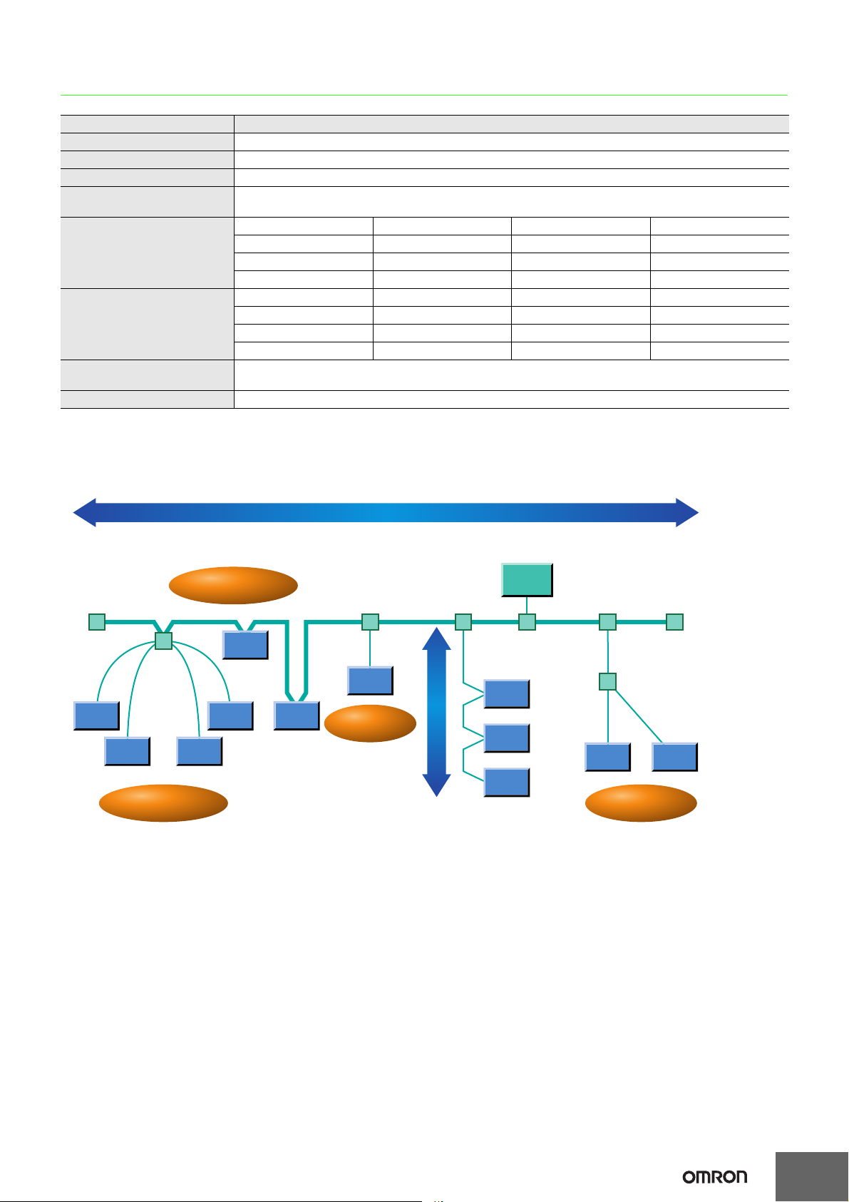
Trunk Line Length (100 m: 500,000 bps; 250 m: 250,000 bps; or 500 m: 125,000 bps)
Multidrop
Star Connections
T-Branch
Branching to
Branch Lines
(Branch line length: 6 m max.)
Communications Specifications
Item Specifications
Communications protocol DeviceNet
Connection methods Multi-drop and T-branch connections can be combined (for trunk and branch lines) *1
Baud rate 500 Kbps, 250 Kbps, or 125 Kbps
Communications media
Communications distances for
special 5-wire cables
Communications distances for
special 4-wire flat cables
Communications
power supply
Max. number of nodes 64 nodes (including Masters, Slaves, and Configurator)
*1. Terminators are required at both ends of trunk line.
*2. Indicates the maximum network length when thick cables are used. Reduce the network length to 100 m max. when using thin cables.
Special 5-wire cables (2 signal lines, 2 power lines, 1 shield line)
Special 4-wire flat cables (2 signal lines, 2 power lines)
Baud rate Network length Branch line length Total branch line length
500 kbps 100 m max. 6 m max. 39 m max.
250 kbps 250 m max. *2 6 m max. 78 m max.
125 kbps 500 m max. *2 6 m max. 156 m max.
Baud rate Network length Branch line length Total branch line length
500 kbps 75 m max. 6 m max. 35 m max.
250 kbps 150 m max. 6 m max. 48 m max.
125 kbps 265 m max. 6 m max. 135 m max.
24 V DC supplied externally
Network Specifications
2
 Loading...