

Page 1

CS-series DeviceNet Unit: CS1W-DRM21
CJ-series DeviceNet Unit: CJ1W-DRM21
Operation Manual
Revised July 2001
Page 2

iv
Page 3

Notice:
OMRON products are manufactured for use according to proper procedures by a qualified operator
and only for the purposes described in this manual.
The following conventions are used to indicate and classify precautions in this manual. Always heed
the information provided with them. Failure to heed precautions can result in injury to people or damage to property.
!DANGER
!WARNING
!Caution
Indicates an imminently hazardous situation which, if not avoided, will result in death or
serious injury.
Indicates a potentially hazardous situation which, if not avoided, could result in death or
serious injury.
Indicates a potentially hazardous situation which, if not avoided, may result in minor or
moderate injury, or property damage.
OMRON Product References
All OMRON products are capitalized in this manual. The word “Unit” is also capitalized when it refers to
an OMRON product, regardless of whether or not it appears in the proper name of the product.
The abbreviation “Ch,” which appears in some displays and on some OMRON products, often means
“word” and is abbreviated “Wd” in documentation in this sense.
The abbreviation “PC” means Programmable Controller and is not used as an abbreviation for anything else.
Visual Aids
The following headings appear in the left column of the manual to help you locate different types of
information.
Note Indicates information of particular interest for efficient and convenient opera-
tion of the product.
Reference Indicates supplementary information on related topics that may be of interest
to the user.
1,2,3... 1. Indicates lists of one sort or another, such as procedures, checklists, etc.
v
Page 4

Trademarks and Copyrights
r
f
DeviceNet is a registered trademark of the Open DeviceNet Vendor Association, Inc.
Windows, Windows 95, Windows 98, Windows Me, Windows NT, and Windows 2000 are registered
trademarks of the Microsoft Corporation.
Other product names and company names in this manual are trademarks or registered trademarks of
their respective companies.
The copyright of the DeviceNet Unit belongs to OMRON Corporation.
OMRON, 2000
All rights reserved. No part of this publication may be reproduced, stored in a retrieval system, or transmitted, in any form, o
by any means, mechanical, electronic, photocopying, recording, or otherwise, without the prior written permission o
OMRON.
No patent liability is assumed with respect to the use of the information contained herein. Moreover, because OMRON is constantly striving to improve its high-quality products, the information contained in this manual is subject to change without
notice. Every precaution has been taken in the preparation of this manual. Nevertheless, OMRON assumes no responsibility
for errors or omissions. Neither is any liability assumed for damages resulting from the use of the information contained in
this publication.
vi
Page 5

TABLE OF CONTENTS
PRECAUTIONS . . . . . . . . . . . . . . . . . . . . . . . . . . . . . . . . xi
1 Intended Audience . . . . . . . . . . . . . . . . . . . . . . . . . . . . . . . . . . . . . . . . . . . . . . . . . xii
2 General Precautions . . . . . . . . . . . . . . . . . . . . . . . . . . . . . . . . . . . . . . . . . . . . . . . . xii
3 Safety Precautions. . . . . . . . . . . . . . . . . . . . . . . . . . . . . . . . . . . . . . . . . . . . . . . . . . xii
4 Operating Environment Precautions . . . . . . . . . . . . . . . . . . . . . . . . . . . . . . . . . . . . xiii
5 Application Precautions . . . . . . . . . . . . . . . . . . . . . . . . . . . . . . . . . . . . . . . . . . . . . xiv
6 Conformance to EC Directives . . . . . . . . . . . . . . . . . . . . . . . . . . . . . . . . . . . . . . . . xvi
SECTION 1
Features and System Configuration . . . . . . . . . . . . . . . . 1
1-1 Overview of DeviceNet . . . . . . . . . . . . . . . . . . . . . . . . . . . . . . . . . . . . . . . . . . . . . . 2
1-2 DeviceNet Unit Features . . . . . . . . . . . . . . . . . . . . . . . . . . . . . . . . . . . . . . . . . . . . . 15
1-3 Specifications . . . . . . . . . . . . . . . . . . . . . . . . . . . . . . . . . . . . . . . . . . . . . . . . . . . . . 21
1-4 Comparison with Previous Models . . . . . . . . . . . . . . . . . . . . . . . . . . . . . . . . . . . . . 29
1-5 Outline of the Configurator . . . . . . . . . . . . . . . . . . . . . . . . . . . . . . . . . . . . . . . . . . . 33
1-6 Basic Operating Procedures . . . . . . . . . . . . . . . . . . . . . . . . . . . . . . . . . . . . . . . . . . 36
1-7 List of Usage Methods by Purpose . . . . . . . . . . . . . . . . . . . . . . . . . . . . . . . . . . . . . 42
SECTION 2
Nomenclature and Installation . . . . . . . . . . . . . . . . . . . . 45
2-1 Nomenclature and Functions . . . . . . . . . . . . . . . . . . . . . . . . . . . . . . . . . . . . . . . . . 46
2-2 Installing the DeviceNet Unit . . . . . . . . . . . . . . . . . . . . . . . . . . . . . . . . . . . . . . . . . 51
SECTION 3
Allocated CIO and DM Words . . . . . . . . . . . . . . . . . . . . 57
3-1 Overview of Word Allocations . . . . . . . . . . . . . . . . . . . . . . . . . . . . . . . . . . . . . . . . 58
3-2 Allocated CIO Area Words . . . . . . . . . . . . . . . . . . . . . . . . . . . . . . . . . . . . . . . . . . . 60
3-3 Allocated DM Area Words . . . . . . . . . . . . . . . . . . . . . . . . . . . . . . . . . . . . . . . . . . . 81
SECTION 4
Remote I/O Master Communications . . . . . . . . . . . . . . . 91
4-1 Master Remote I/O Communications . . . . . . . . . . . . . . . . . . . . . . . . . . . . . . . . . . . 92
4-2 Scan List . . . . . . . . . . . . . . . . . . . . . . . . . . . . . . . . . . . . . . . . . . . . . . . . . . . . . . . . . 99
4-3 Fixed Allocations . . . . . . . . . . . . . . . . . . . . . . . . . . . . . . . . . . . . . . . . . . . . . . . . . . 101
4-4 User-set Allocations . . . . . . . . . . . . . . . . . . . . . . . . . . . . . . . . . . . . . . . . . . . . . . . . 107
4-5 Starting and Stopping Remote I/O Communications . . . . . . . . . . . . . . . . . . . . . . . 116
4-6 Example of Ladder Programming for Remote I/O Communications. . . . . . . . . . . 116
4-7 Errors that May Occur in Remote I/O Communications . . . . . . . . . . . . . . . . . . . . 118
vii
Page 6

TABLE OF CONTENTS
SECTION 5
Remote I/O Slave Communications. . . . . . . . . . . . . . . . . 121
5-1 Slave Remote I/O Communications . . . . . . . . . . . . . . . . . . . . . . . . . . . . . . . . . . . 122
5-2 Fixed Allocations . . . . . . . . . . . . . . . . . . . . . . . . . . . . . . . . . . . . . . . . . . . . . . . . . . 125
5-3 User-set Allocations. . . . . . . . . . . . . . . . . . . . . . . . . . . . . . . . . . . . . . . . . . . . . . . . 126
SECTION 6
Message Communications . . . . . . . . . . . . . . . . . . . . . . . . 133
6-1 Overview . . . . . . . . . . . . . . . . . . . . . . . . . . . . . . . . . . . . . . . . . . . . . . . . . . . . . . . . 134
6-2 FINS Commands and Responses. . . . . . . . . . . . . . . . . . . . . . . . . . . . . . . . . . . . . . 141
6-3 Using FINS Message Communications. . . . . . . . . . . . . . . . . . . . . . . . . . . . . . . . . 145
6-4 Sending Explicit Messages . . . . . . . . . . . . . . . . . . . . . . . . . . . . . . . . . . . . . . . . . . 158
6-5 Receiving Explicit Messages . . . . . . . . . . . . . . . . . . . . . . . . . . . . . . . . . . . . . . . . . 165
SECTION 7
Other Functions. . . . . . . . . . . . . . . . . . . . . . . . . . . . . . . . . 181
7-1 Connecting to the CX-Programmer via the DeviceNet . . . . . . . . . . . . . . . . . . . . . 182
7-2 Memory Card Backup Functions. . . . . . . . . . . . . . . . . . . . . . . . . . . . . . . . . . . . . . 186
SECTION 8
Communications Timing . . . . . . . . . . . . . . . . . . . . . . . . . 189
8-1 Remote I/O Communications Characteristics . . . . . . . . . . . . . . . . . . . . . . . . . . . . 190
8-2 Message Communications . . . . . . . . . . . . . . . . . . . . . . . . . . . . . . . . . . . . . . . . . . . 196
SECTION 9
Troubleshooting and Maintenance . . . . . . . . . . . . . . . . . 199
9-1 Troubleshooting with the DeviceNet Unit Indicators . . . . . . . . . . . . . . . . . . . . . . 200
9-2 Error Log Functions. . . . . . . . . . . . . . . . . . . . . . . . . . . . . . . . . . . . . . . . . . . . . . . . 218
9-3 Troubleshooting . . . . . . . . . . . . . . . . . . . . . . . . . . . . . . . . . . . . . . . . . . . . . . . . . . . 222
9-4 Maintenance and Replacement . . . . . . . . . . . . . . . . . . . . . . . . . . . . . . . . . . . . . . . 225
Appendices
A Allocation Differences from C200H DeviceNet Master Units . . . . . . . . . . . . . . . 229
B DeviceNet Connections . . . . . . . . . . . . . . . . . . . . . . . . . . . . . . . . . . . . . . . . . . . . 235
C FINS Commands and Responses for DeviceNet Units . . . . . . . . . . . . . . . . . . . . 241
D Memory Card Backup Functions . . . . . . . . . . . . . . . . . . . . . . . . . . . . . . . . . . . . . 247
E Multi-vendor Applications . . . . . . . . . . . . . . . . . . . . . . . . . . . . . . . . . . . . . . . . . . 251
F DeviceNet Explicit Message Send Command for Other Manufacturer Nodes . . 261
Index . . . . . . . . . . . . . . . . . . . . . . . . . . . . . . . . . . . . . . . . . . 263
Revision History . . . . . . . . . . . . . . . . . . . . . . . . . . . . . . . . 267
viii
Page 7

About this Manual:
This manual describes the installation and operation of CS1W-DRM21 DeviceNet Unit for SYSMAC
CJ-series PLCs and the CJ1W-DRM21 DeviceNet Unit for SYSMAC CJ-series PLCs, and includes the
sections described below.
Please read this manual and all manuals for related products carefully and be sure you understand the
information provided before attempting to install and operate the DeviceNet Unit. Be sure to read the
precautions provided in the following section.
Section 1 provides an overview of the DeviceNet network, including features, specifications, and system.
Section 2 describes the nomenclature and installation of the DeviceNet Unit.
Section 3 describes the words allocated to the DeviceNet Unit in the CIO Area and DM Area. These
words both enable controlling the DeviceNet Unit and accessing Unit and network status.
Section 4 describes the remote I/O communications performed as a master by the DeviceNet Unit.
Section 5 describes the remote I/O communications performed as a slave by the DeviceNet Unit.
Section 6 describes message communications using FINS commands sent from the ladder program
in the CPU Unit of the PC.
Section 7 describes connecting to CX-Programmer via the DeviceNet and the Memory Card backup
function.
Section 8 describes the time required for remote I/O communications and message communications.
Section 9 describes error processing, periodic maintenance, and troubleshooting procedures needed
to keep the DeviceNet network operating properly. We recommend reading through the error processing procedures before operation so that operating errors can be identified and corrected more quickly.
The Appendices provide information on allocation differences with C200H-series DeviceNet Units,
DeviceNet connections, remote programming and monitoring, Memory Card backups, FINS commands and responses, sending DeviceNet explicit message to Non-OMRON nodes, and multi-vendor
applications.
The following manuals provide information on the DeviceNet and OMRON DeviceNet products.
Manual Products Contents Cat. No.
CS/CJ-series DeviceNet
Unit Operation Manual
(This manual)
DeviceNet
Operation Manual
DeviceNet Configurator
@
Ver. 2.
Operation Manual
DeviceNet Slaves Operation Manual
DeviceNet MULTIPLE I/O
TERMINAL Operation
Manual
CS1W-DRM21and CJ1W-DRM21
DeviceNet Units
CVM1-DRM21-V1 DeviceNet Master Unit
C200HW-DRM21-V1 DeviceNet Master Unit
CQM1-DRT21 I/O Link Unit
DRT1-series DeviceNet Slaves
GT1-series DeviceNet Slaves
WS02-CFDC1-E DeviceNet Configurator
3G8F5-DRM21 ISA Board
3G8E2-DRM21 PCMCIA Board
C200HW-DRT21
CQM1-DRT21
DRT1 Series
DRT1-COM
GT1 Series
Information on CS/CJseries DeviceNet Units.
Information on C200Hseries, CVM1, and CVseries DeviceNet Units, as
well as general DeviceNet
communications specifications and wiring methods.
Information on using the
Configurator.
Information on DeviceNet
Slaves.
Information on MULTIPLE
I/O TERMINALs, one type
of DeviceNet slave.
W380
W267
W382
W347
W348
ix
Page 8

Manual Products Contents Cat. No.
SYSMAC CS/CJ Series
Communication Commands Reference Manual
CX-Net
Operation Manual
CS1G/H-CPU
CS1W-SCB21/41 Serial Communications
Boards
CS1W-SCU21 Serial Communications Unit
WS02-CXPC1-EV
@@
-E CPU Units
@
Information on FINS and
Host Link commands that
can be sent to CS/CJ-series
CPU Units.
Information on setting and
monitoring networks, such
as the use of routing tables.
W342
W362
!WARNING
x
Failure to read and understand the information provided in this manual may result in personal injury or death, damage to the product, or product failure. Please read each section
in its entirety and be sure you understand the information provided in the section and
related sections before attempting any of the procedures or operations given.
Page 9

PRECAUTIONS
This section provides general precautions for using the DeviceNet Unit and related devices.
The information contained in this section is important for the safe and reliable application of the DeviceNet Unit
and Programmable Controller (PC) You must read this section and understand the information contained before
attempting to set up or operate a DeviceNet Unit as part of a PC.
1 Intended Audience . . . . . . . . . . . . . . . . . . . . . . . . . . . . . . . . . . . . . . . . . . . . . xii
2 General Precautions . . . . . . . . . . . . . . . . . . . . . . . . . . . . . . . . . . . . . . . . . . . . xii
3 Safety Precautions. . . . . . . . . . . . . . . . . . . . . . . . . . . . . . . . . . . . . . . . . . . . . . xii
4 Operating Environment Precautions . . . . . . . . . . . . . . . . . . . . . . . . . . . . . . . . xiii
5 Application Precautions . . . . . . . . . . . . . . . . . . . . . . . . . . . . . . . . . . . . . . . . . xiv
6 Conformance to EC Directives . . . . . . . . . . . . . . . . . . . . . . . . . . . . . . . . . . . . xvi
6-1 Applicable Directives . . . . . . . . . . . . . . . . . . . . . . . . . . . . . . . . . . . . xvi
6-2 Concepts . . . . . . . . . . . . . . . . . . . . . . . . . . . . . . . . . . . . . . . . . . . . . . xvi
6-3 Conformance to EC Directives . . . . . . . . . . . . . . . . . . . . . . . . . . . . . xvi
xi
Page 10

Intended Audience 1
1 Intended Audience
This manual is intended for the following personnel, who must also have
knowledge of electrical systems (an electrical engineer or the equivalent).
• Personnel in charge of installing FA systems.
• Personnel in charge of designing FA systems.
• Personnel in charge of managing FA systems and facilities.
2 General Precautions
The user must operate the product according to the performance specifications described in the operation manuals.
Before using the product under conditions which are not described in the
manual or applying the product to nuclear control systems, railroad systems,
aviation systems, vehicles, combustion systems, medical equipment, amusement machines, safety equipment, and other systems, machines, and equipment that may have a serious influence on lives and property if used
improperly, consult your OMRON representative.
Make sure that the ratings and performance characteristics of the product are
sufficient for the systems, machines, and equipment, and be sure to provide
the systems, machines, and equipment with double safety mechanisms.
This manual provides information for installing and operating the DeviceNet
Unit. Be sure to read this manual before operation and keep this manual close
at hand for reference during operation.
!WARNING
It is extremely important that a PC and all PC Units be used for the specified
purpose and under the specified conditions, especially in applications that can
directly or indirectly affect human life. You must consult with your OMRON
representative before applying a PC System to the above mentioned applications.
3 Safety Precautions
!WARNING
!WARNING
Never attempt to disassemble a Unit or touch the inside of Unit while power is
being supplied. Doing so may result in serious electrical shock or electrocution.
Provide safety measures in external circuits, i.e., not in the Programmable
Controller (CPU Unit including associated Units; referred to as “PC”), in order
to ensure safety in the system if an abnormality occurs due to malfunction of
the PC or another external factor affecting the PC operation. Not doing so may
result in serious accidents.
• Emergency stop circuits, interlock circuits, limit circuits, and similar safety
measures must be provided in external control circuits.
• The PC will turn OFF all outputs when its self-diagnosis function detects
any error or when a severe failure alarm (FALS) instruction is executed.
As a countermeasure for such errors, external safety measures must be
provided to ensure safety in the system.
• The PC outputs may remain ON or OFF due to deposition or burning of
the output relays or destruction of the output transistors. As a counter-
xii
Page 11

Operating Environment Precautions 4
measure for such problems, external safety measures must be provided
to ensure safety in the system.
• When the 24-VDC output (service power supply to the PC) is overloaded
or short-circuited, the voltage may drop and result in the outputs being
turned OFF. As a countermeasure for such problems, external safety
measures must be provided to ensure safety in the system.
!WARNING
!Caution
!Caution
The CPU Unit refreshes I/O even when the program is stopped (i.e., even in
PROGRAM mode). Confirm safety thoroughly in advance before changing the
status of any part of memory allocated to I/O Units, Special I/O Units, or CPU
Bus Units. Any changes to the data allocated to any Unit may result in unexpected operation of the loads connected to the Unit. Any of the following operation may result in changes to memory status.
• Transferring I/O memory data to the CPU Unit from a Programming
Device.
• Changing present values in memory from a Programming Device.
• Force-setting/-resetting bits from a Programming Device.
• Transferring I/O memory files from a Memory Card or EM file memory to
the CPU Unit.
• Transferring I/O memory from a host computer or from another PC on a
network.
Execute online edit only after confirming that no adverse effects will be
caused by extending the cycle time. Otherwise, the input signals may not be
readable.
Confirm safety at the destination node before transferring a program to
another node or changing contents of the I/O memory area. Doing either of
these without confirming safety may result in injury.
4 Operating Environment Precautions
Do not install the Unit in any of the following locations.
• Locations subject to direct sunlight.
• Locations subject to temperatures or humidities outside the range speci-
fied in the specifications.
• Locations subject to condensation as the result of severe changes in temperature.
• Locations subject to corrosive or flammable gases.
• Locations subject to dust (especially iron dust) or salt.
• Locations subject to exposure to water, oil, or chemicals.
• Locations subject to shock or vibration.
Provide proper shielding when installing in the following locations:
• Locations subject to static electricity or other sources of noise.
• Locations subject to strong electromagnetic fields.
• Locations subject to possible exposure to radiation.
• Locations near to power supply lines.
xiii
Page 12

Application Precautions 5
!Caution
The operating environment of the PC System can have a large effect on the
longevity and reliability of the system. Improper operating environments can
lead to malfunction, failure, and other unforeseeable problems with the PC
System. Be sure that the operating environment is within the specified conditions at installation and remains within the specified conditions during the life
of the system.
5 Application Precautions
Observe the following precautions when using the DeviceNet Unit.
!WARNING
!Caution
Failure to abide by the following precautions could lead to serious or possibly
fatal injury. Always heed these precautions.
• Always connect to a class-3 ground (100
Units.
Failure to abide by the following precautions could lead to faulty operation or
the PC or the system or could damage the PC or PC Units. Always heed
these precautions.
• Install double safety mechanisms to ensure safety against incorrect signals that may be produced by broken signal lines or momentary power
interruptions.
• Enable the scan list to before operating the system.
• When adding a new node to the network, make sure that the baud rate is
the same as other nodes.
• Use specified communications cables.
• Do not extend connection distances beyond the ranges given in the spec-
ifications.
• Always turn OFF the power supply to the personal computer, Slaves, and
Communications Units before attempting any of the following.
• Mounting or dismounting the DeviceNet Unit, Power Supply Units, I/O
Units, CPU Units, or any other Units.
• Assembling a Unit.
• Setting DIP switches or rotary switches.
• Connecting or wiring the cables.
• Connecting or disconnecting connectors.
• Be sure that the terminal blocks, connectors, Memory Units, expansion
cables, and other items with locking devices are properly locked into
place. Improper locking may result in malfunction.
• Be sure that all the mounting screws, terminal screws, Unit mounting
screws, and cable connector screws are tightened to the torque specified
in the relevant manuals. Incorrect tightening torque may result in malfunction.
• Leave the label attached to the Unit when wiring. Removing the label may
result in malfunction if foreign matter enters the Unit.
• Remove the label after the completion of wiring to ensure proper heat dissipation. Leaving the label attached may result in malfunction.
• Always use the power supply voltage specified in this manual.
Ω or less) when installing the
xiv
Page 13

Application Precautions 5
• Double-check all the wiring and connection of terminal blocks and connectors before mounting the Units.
• Use crimp terminals for wiring. Do not connect bare stranded wires
directly to terminals.
• Observe the following precautions when wiring the communications
cable.
• Separate the communications cables from the power lines or high-tension lines.
• Do not bend the communications cables.
• Do not pull on the communications cables.
• Do not place heavy objects on top of the communications cables.
• Be sure to wire communications cable inside ducts.
• Use appropriate communications cables.
• Take appropriate measures to ensure that the specified power with the
rated voltage and frequency is supplied in places where the power supply
is unstable. An incorrect power supply may result in malfunction.
• Install external breakers and take other safety measures against short-circuiting in external wiring. Insufficient safety measures against short-circuiting may result in burning.
• Double-check all the wiring and switch settings before turning ON the
power supply.
• Check the user program for proper execution before actually running it on
the Unit. Not checking the program may result in an unexpected operation.
• Confirm that no adverse effect will occur in the system before attempting
any of the following. Not doing so may result in an unexpected operation.
• Changing the operating mode of the PC.
• Force-setting/force-resetting any bit in memory.
• Changing the present value of any word or any set value in memory.
• After replacing Units, resume operation only after transferring to the new
CPU Unit and/or Special I/O Units the contents of the DM Area, HR Area,
and other data required for resuming operation. Not doing so may result in
an unexpected operation.
• When transporting or storing the product, cover the PCBs with electrically
conductive materials to prevent LSIs and ICs from being damaged by
static electricity, and also keep the product within the specified storage
temperature range.
• When transporting the Unit, use special packing boxes and protect it from
being exposed to excessive vibration or impacts during transportation.
• Do not attempt to disassemble, repair, or modify any Units.
xv
Page 14

Conformance to EC Directives 6
6 Conformance to EC Directives
6-1 Applicable Directives
• EMC Directives
6-2 Concepts
EMC Directives
OMRON devices that comply with EC Directives also conform to the related
EMC standards so that they can be more easily built into other devices or
machines. The actual products have been checked for conformity to EMC
standards. (See the following note.) Whether the products conform to the
standards in the system used by the customer, however, must be checked by
the customer.
EMC-related performance of the OMRON devices that comply with EC Directives will vary depending on the configuration, wiring, and other conditions of
the equipment or control panel in which the OMRON devices are installed.
The customer must, therefore, perform final checks to confirm that devices
and the overall machine conform to EMC standards.
Note Applicable EMS (Electromagnetic Susceptibility) and EMI (Electromagnetic
Interference standards in the EMC (Electromagnetic Compatibility) standards
are as follows:
Unit EMS EMI
CS1W-DRM21 EN50082-2 EN50081-2
CJ1W-DRM21 EN61000-6-2
6-3 Conformance to EC Directives
DeviceNet products that meet EC directives must be installed as follows:
1,2,3... 1. DeviceNet Units are designed for installation inside control panels. All De-
viceNet Units must be installed within control panels.
2. Used reinforced insulation or double insulation for the DC power supplies
used for the communications power supply, internal circuit power supply,
and the I/O power supplies.
3. DeviceNet products that meet EC directives also meet the common emission standard (EN50081-2). When DeviceNet products are built into equipment, however, the measure necessary to ensure that the standard is met
will vary with the overall configuration of the control panel, the other devices connected to the control panel, and other conditions. You must therefore confirm that EC directives are met for the overall machine or device,
particularly for the radiated emission requirement (10 m).
The following examples show means of reducing noise.
1,2,3.... 1. Noise from the communications cable can be reduced by installing a ferrite
core on the communications cable within 10 cm of the DeviceNet Unit.
xvi
Page 15

Conformance to EC Directives 6
Ferrite Core (Data Line Filter): 0443-164151 (manufacturered by
Impedance specifications
25 MHZ: 156 Ω
100 MHZ: 250 Ω
30 mm
13 mm
29 mm
Fair-Rite Products Co., Ltd.)
33 mm
2. Wire the control panel withas thick and short electric lines as possible and
ground to 10 0 Ω min.
3. Keep DeviceNet communications cables as short as possible and ground
to 100 Ω min.
xvii
Page 16

SECTION 1
Features and System Configuration
This section provides an overview of the DeviceNet network, including features, specifications, and system configurations.
1-1 Overview of DeviceNet . . . . . . . . . . . . . . . . . . . . . . . . . . . . . . . . . . . . . . . . . . 2
1-1-1 Overall System Configuration . . . . . . . . . . . . . . . . . . . . . . . . . . . . . 3
1-1-2 Applicable Units and DeviceNet Functions . . . . . . . . . . . . . . . . . . . 6
1-1-3 Masters . . . . . . . . . . . . . . . . . . . . . . . . . . . . . . . . . . . . . . . . . . . . . . . 9
1-1-4 Types of Slave . . . . . . . . . . . . . . . . . . . . . . . . . . . . . . . . . . . . . . . . . . 9
1-1-5 DeviceNet Configurator . . . . . . . . . . . . . . . . . . . . . . . . . . . . . . . . . . 15
1-2 DeviceNet Unit Features . . . . . . . . . . . . . . . . . . . . . . . . . . . . . . . . . . . . . . . . . 15
1-3 Specifications . . . . . . . . . . . . . . . . . . . . . . . . . . . . . . . . . . . . . . . . . . . . . . . . . 21
1-3-1 DeviceNet Unit . . . . . . . . . . . . . . . . . . . . . . . . . . . . . . . . . . . . . . . . . 21
1-4 Comparison with Previous Models . . . . . . . . . . . . . . . . . . . . . . . . . . . . . . . . . 29
1-5 Outline of the Configurator . . . . . . . . . . . . . . . . . . . . . . . . . . . . . . . . . . . . . . . 33
1-5-1 Models . . . . . . . . . . . . . . . . . . . . . . . . . . . . . . . . . . . . . . . . . . . . . . . 33
1-5-2 Configurator Specifications . . . . . . . . . . . . . . . . . . . . . . . . . . . . . . . 34
1-6 Basic Operating Procedures . . . . . . . . . . . . . . . . . . . . . . . . . . . . . . . . . . . . . . 36
1-6-1 Network Installation Procedure . . . . . . . . . . . . . . . . . . . . . . . . . . . . 36
1-6-2 Hardware Preparations for Communications . . . . . . . . . . . . . . . . . . 36
1-6-4 Procedures Prior to Starting Communications . . . . . . . . . . . . . . . . . 38
1-7 List of Usage Methods by Purpose . . . . . . . . . . . . . . . . . . . . . . . . . . . . . . . . . 42
1
Page 17

Overview of DeviceNet Section 1-1
1-1 Overview of DeviceNet
DeviceNet is a multi-bit, multi-vendor network that combines controls and data
on a machine/line-control level and that conforms to DeviceNet open field network specifications.
Three types of communications are supported: 1) Remote I/O master communications that automatically transfer I/O between slaves and the CPU Unit to
which a DeviceNet Unit is mounted without any special programming in the
CPU Unit, 2) Remote I/O slave communications that automatically transfer I/O
between the Master and the CPU Unit to which a DeviceNet Unit is mounted,
and 3) Message communications that read/write messages, control operation,
or perform other functions for other CPU Units to which a DeviceNet Unit is
mounted and slaves. Message communications are achieved by executing
specific instructions (SEND (192), RECV (193), and CMND (194)) from the
program in the CPU Unit to which the DeviceNet Unit is mounted.
DeviceNet functions
1,2,3... 1. Without the Configurator Software Tool
Remote I/O master communications
Remote I/O slave communications
Message communications
Fixed allocations
User-set allocations
Fixed allocations
User-set allocations
Explicit message communications
FINS message communications
The following functions are supported with a CS/CJ-series DeviceNet Unit.
a) I/O area words can be flexibly allocated for remote I/O Master and
Slave communications. Three types of fixed allocations as well as
user-set allocations through allocated DM Area words are possible.
b) More than one DeviceNet Unit can be mounted under a single PC.
c) More than one DeviceNet Unit can be connected in a single network.
With the Configurator, remote I/O can be allocated in any order, i.e.,
not necessarily in the other of node addresses.
Note The Configurator that is connected through a dedicated Board or
Card uses one node in the DeviceNet network. It does not use a
node if it is connected by a serial line.
2. A CS/CJ-series DeviceNet Unit can function as either a master or slave in
remote I/O communications. Both can be used simultaneously.
3. With a CS/CJ-series DeviceNet Unit, the DeviceNet network can be treated exactly like a Controller Link, Ethernet, or other network for message
communications or remote programming and monitoring by a CX-Programmer.
2
Page 18
Overview of DeviceNet Section 1-1
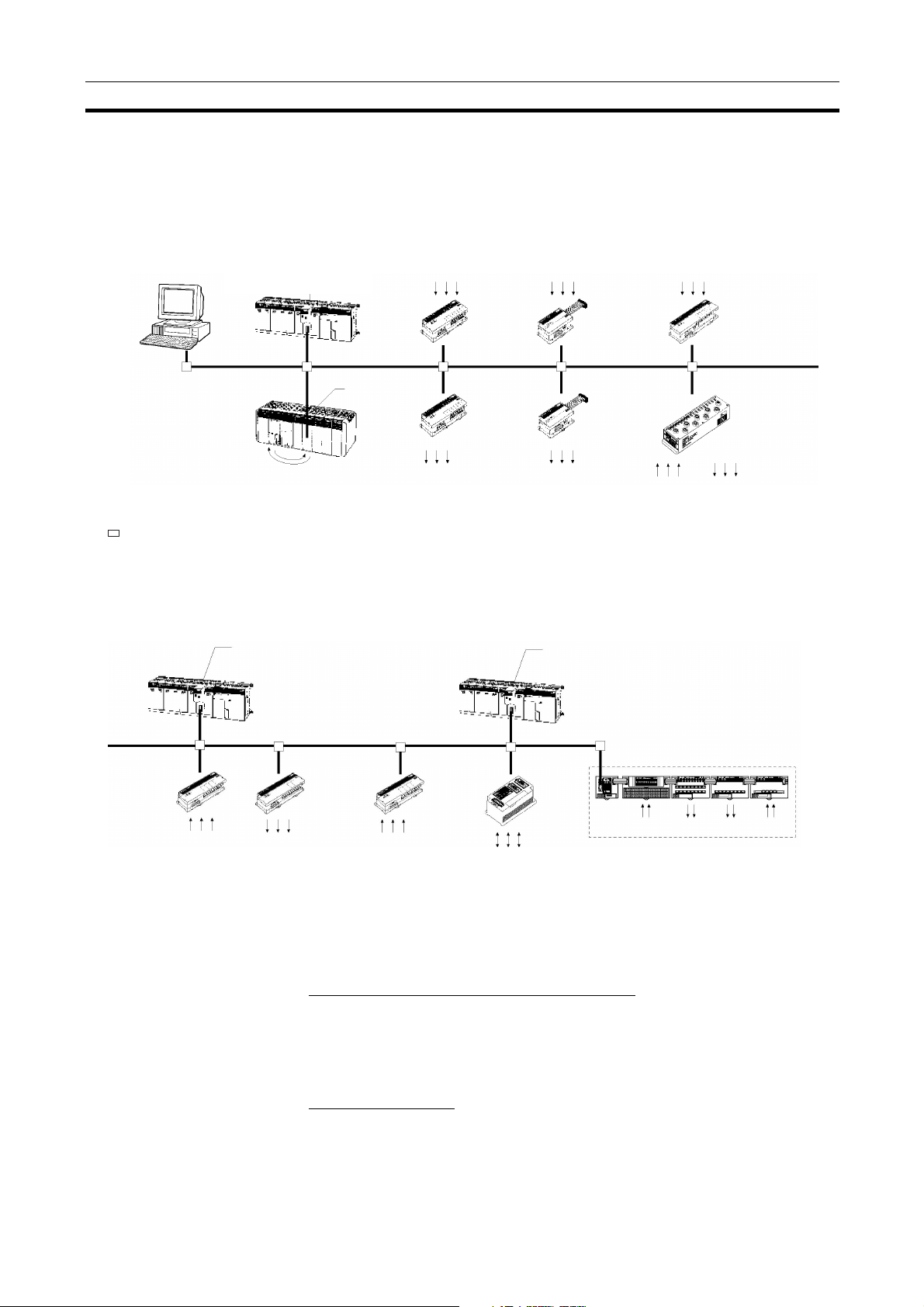
1-1-1 Overall System Configuration
DeviceNet Unit or
DeviceNet Master Unit
CS Series
CS1W-DRM21
CJ Series
CJ1W- DRM21
DeviceNet
Configurator
(personal computer)
: T-branch Taps or multi-drop connections
CQM1
C200HZ/HX/HG/E/HS:
C200HW-DRM21-V1
CVM1/CV Series:
CVM1-DRM21-V1
Photoelectric
,
I/O Link
Unit
sensors, proximity sensors, limit
switches, etc.
Input
Te r mi n a l
Output
Terminal
Solenoids,
valves, etc.
Photoelectric
sensors, proximity sensors, limit
switches, etc.
Input Remote
Adapter (used
with Input Block)
Output Remote
Adapter (used
with Output
Block)
Solenoids,
valves, etc.
Photoelectric
sensors or proximity sensors
with connectors
Photoelectric
sensors,
proximity
sensors, limit
switches, etc.
Sensor
Te r mi n a l
Environment-resistant Terminal
(Inputs, outputs,
or mixed I/O)
Solenoids,
valves, etc.
Analog
Input
Terminal
Analog sensors,
etc.
Master Features
DeviceNet Unit or
DeviceNet Master Unit
(See note.)
Analog
Output
Terminal
Inverters,
valves, etc.
Temperature Input Terminal
Thermocouple,
platinum resistance
thermometer
Bar code
readers, etc.
C200H I/O Link Unit
RS-232C
Unit
Inputs Outputs Outputs
MULTIPLE I/O TERMINAL
Inputs
Note The Configurator is required if more than one Master is connected in a single
network when a CVM1-DRM21-V1 or C200HW-DRM21-V1 is used.
DeviceNet Master Units and DeviceNet Units
Support remote I/O communications between OMRON PCs (CS-series, CJseries, CVM1, CV-series, or C200HX/HG/HE/HS) and slaves.
Support message communications between OMRON PCs, or between an
OMRON PC and slaves and masters from other companies.
VME Master Boards
Supports remote I/O communications between a VME System and slaves.
3
Page 19

Overview of DeviceNet Section 1-1
Configurator Features
• Enables user-set allocations for remote I/O (choice of node address order,
2 area allocations, etc.).
• Enables serial connection to the Programming Device Port of a PC.
• Enables user settings for DeviceNet remote I/O communications connec-
tions.
• Enables multiple Masters on a single PC.
• Enables multiple Masters in a single network.
Slave Features
I/O Terminals
• Provide general-purpose I/O via terminal blocks (M3).
• Available in the following models:
• 8-point Transistor Input Terminal
• 16-point Transistor Input Terminal
• 8-point Transistor Output Terminal
• 16-point Transistor Output Terminal
Environment-resistant Terminals
• Improved I/O Terminals that conform to IP66 for spatter-, water-, and oilresistance.
• Available in the following models:
• 8-point Transistor Input Terminal
• 8-point Transistor Output Terminal
• 16-point Transistor I/O Terminal (8 inputs and 8 outputs)
Remote Adapters
• Used in combination with G70D and other I/O Blocks to handle relay outputs, power MOS FET Relay outputs, etc.
• Available in 16-point input and 16-point output models.
I/O Link Units
• More than one I/O Link Unit can be mounted to a CQM1 PC.
• Link 16 inputs and 16 outputs between the PC and the Master.
Sensor Terminals
• Accept inputs from photoelectric and proximity sensors with connectors.
• Available in 16-point input and 8-point input/8-point output models.
• Output signals can be used for sensor teaching and external diagnosis.
Analog Input Terminals
• Convert analog inputs to binary.
• Switchable between 2 and 4 input points using the DIP switch.
• Handle inputs of 0 to 5 V, 1 to 5 V, 0 to 10 V, –10 to +10 V, 0 to 20 mA, or
4to20mA.
Analog Output Terminals
• Convert binary data to analog outputs.
• Provides outputs of 1 to 5 V, 0 to 10 V, –10 to +10 V, 0 to 20 mA, or 4 to
20mA.
• Available in models with a resolution of either 1/6,000 or 1/30,000.
4
Page 20

Overview of DeviceNet Section 1-1
Temperature Input Terminals
• Temperature data is input as binary data for 4 inputs.
• Thermocouple and platinum resistance thermometer inputs are available.
C200H I/O Link Units
• Special I/O Slaves that mount to C200HX/HG/HE PCs and read/write
data from the Master to the specified words in the CPU Unit.
• Read and write areas specified for up to 512 bits each (32 words each).
• Any memory area words can be read or written using DeviceNet explicit
messages.
RS-232C Units
• Special I/O Slaves that provide two RS-232C ports and control I/O from
the Masters.
MULTIPLE I/O TERMINALs
• Multiple I/O Units can be combined under a Communications Unit and
treated as a single Slave.
• Special I/O Units, such as Analog I/O Units, and High-speed Counter
Units are also available.
5
Page 21
Overview of DeviceNet Section 1-1
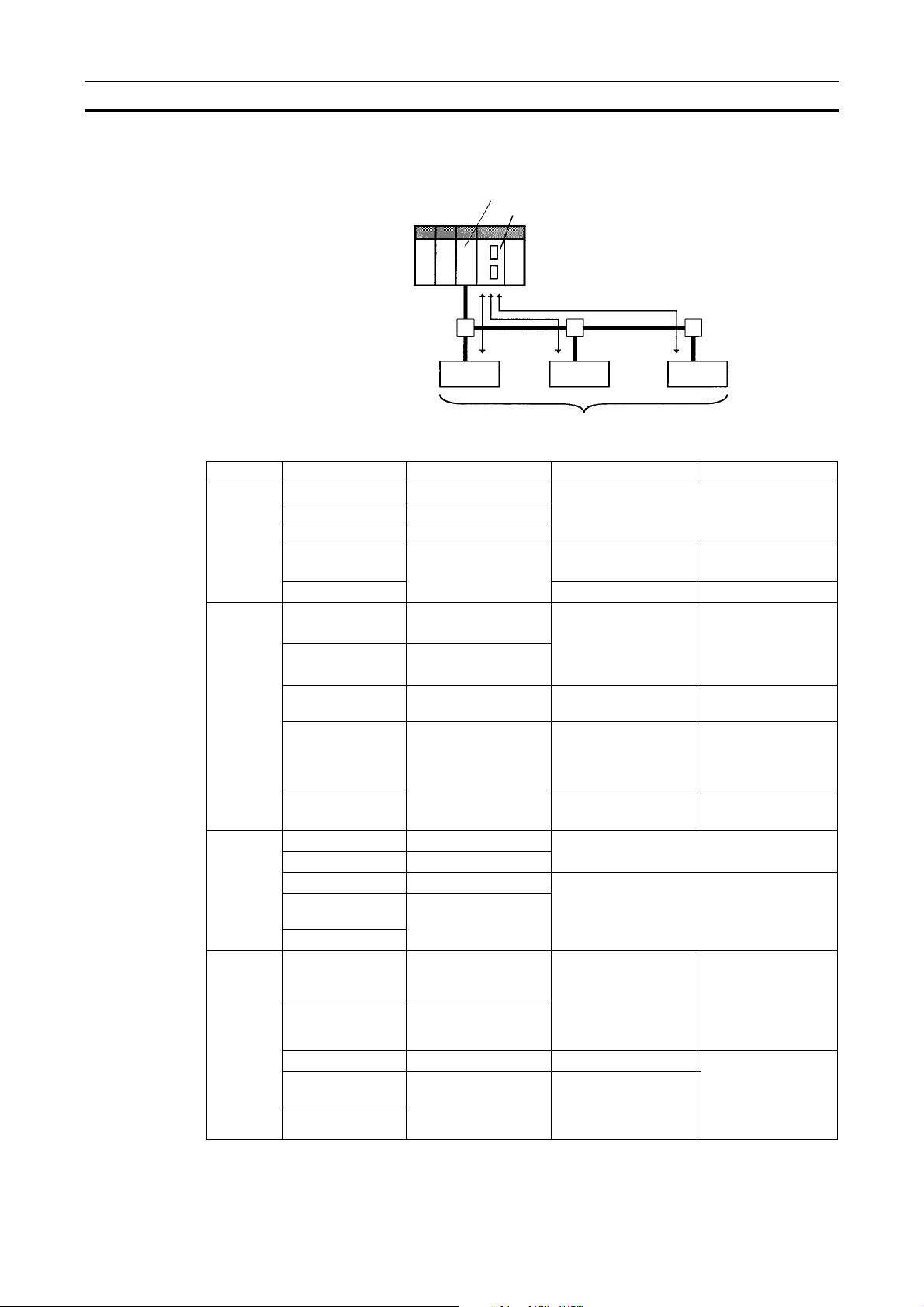
1-1-2 Applicable Units and DeviceNet Functions
Remote I/O Master
DeviceNet Unit (Master)
CPU Unit
Remote I/O communications
DeviceNet
Slaves
Item Master Model Without Configurator With Configurator
Max. No.
of Slave
nodes per
Master
Max. No.
of control
points per
Master
CS Series CS1W-DRM21 63 nodes
CJ Series CJ1W-DRM21
CVM1, CV Series CVM1-DRM21-V1
CS Series,
C200HX/HG/HE
C200HS 32 nodes 63 nodes
CS Series CS1W-DRM21 2,048 pts (64 input /64
CJ Series CJ1W-DRM21
C200HW-DRM21-V1 50 nodes 63 nodes
32,000 pts (500
output words) or
16,000 pts (500 input/
500 output words)
words x 4 blocks)
Max. No.
of I/O
points per
Slave controllable by
Master
Remote I/
O allocation areas
CVM1, CV Series CVM1-DRM21-V1 2,048 pts (64 input/ 64
output words)
CS Series,
C200HX/HG/HE
C200HS 1,024 pts (32 input/32
CS Series CS1W-DRM21 100 input/100 output words
CJ Series CJ1W-DRM21
CVM1, CV Series CVM1-DRM21-V1 32 input/32 output words
CS Series,
C200HX/HG/HE
C200HS
CS Series CS1W-DRM21 CS/CJ DeviceNet
CJ Series CJ1W-DRM21
CVM1, CV Series CVM1-DRM21-V1 DeviceNet Area User-allocated
CS Series,
C200HX/HG/HE
C200HS
C200HW-DRM21-V1 1,600 pts (50 input/50
output words)
output words)
C200HW-DRM21-V1
words in CIO Area,
and user-allocated
words in CIO Area,
DM Area, and other
areas.
C200HW-DRM21-V1 C200H DeviceNet
words in CIO Area
(including dedicated
words/ bits)
6,400 (100 words x
4 blocks
Without messages:
4,800 pts
With messages:
1,600 pts
1,280
User-allocated
words in CIO Area,
DM Area, and other
areas.
words in CIO Area,
DM Area, and other
areas.
6
Page 22
Overview of DeviceNet Section 1-1
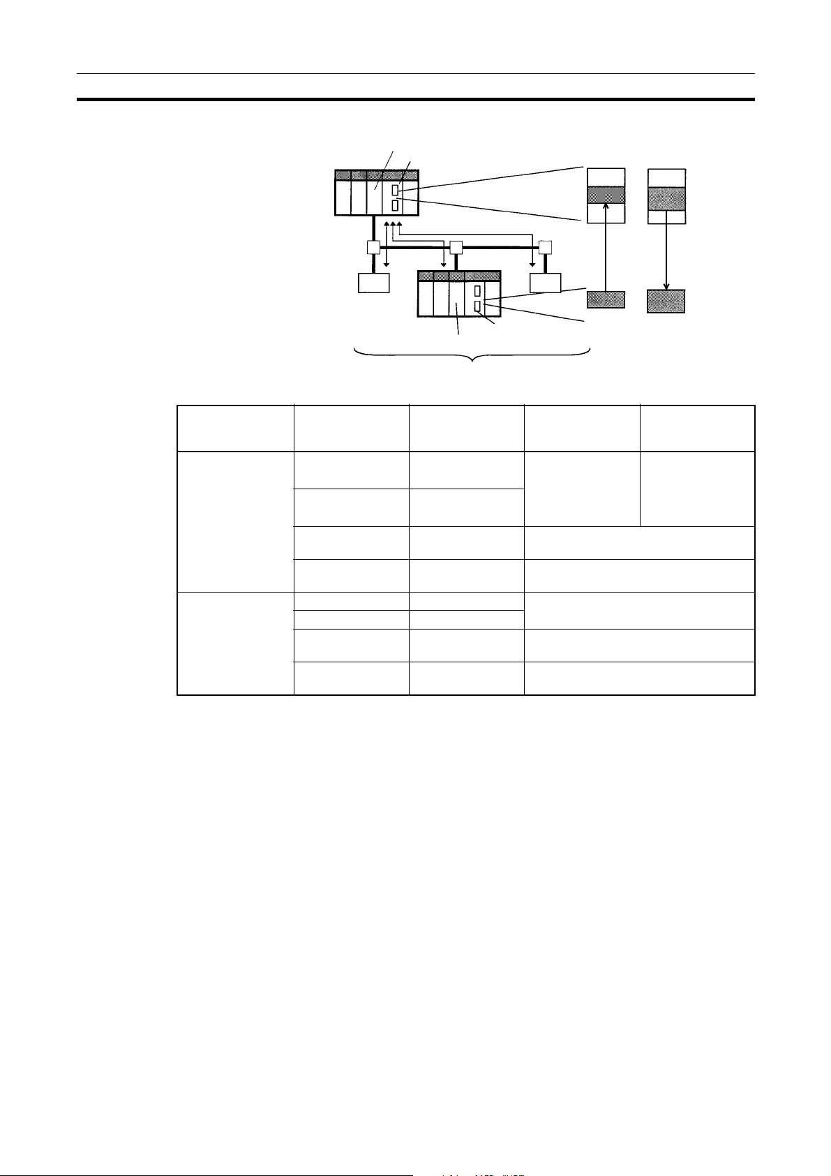
Remote I/O Slave (only Units Mounted in a PC)
DeviceNet Unit (Master)
CPU Unit
IN area OUT area
Item CPU Unit to
Max. No. of I/O pts
per Slave
Allocation areas in
the CPU Unit to
which this Slave is
mounted
Remote I/O communications
DeviceNet Unit (Slave)
which a Slave is
mounted
CS Series CS1W-DRM21 32 pts (1 input/
CJ Series CJ1W-DRM21
CS Series,
C200HX/HG/HE
CQM1H
CQM1 Series
CS Series CS1W-DRM21 CIO, WR, DM, EM, HR
CJ Series CJ1W-DRM21
CS Series,
C200HX/HG/HE
CQM1H
CQM1 Series
C200HW-DRT21 1,024 pts (32 input/32 output words)
CQM1-DRT21 32 pts (1 input/1 output word)
C200HW-DRT21 CIO, DM, EM, AR, LR, T/C
CQM1-DRT21 CIO
DeviceNet
CPU Unit
Slaves
Unit Model Without the
Configurator
1 output word) or
3,200 pts (100
input/100 output
words)
IN area
OUT area
4,800 pts
(100 input words x
2/100 output words
x 1)
With the
Configurator
7
Page 23
Overview of DeviceNet Section 1-1
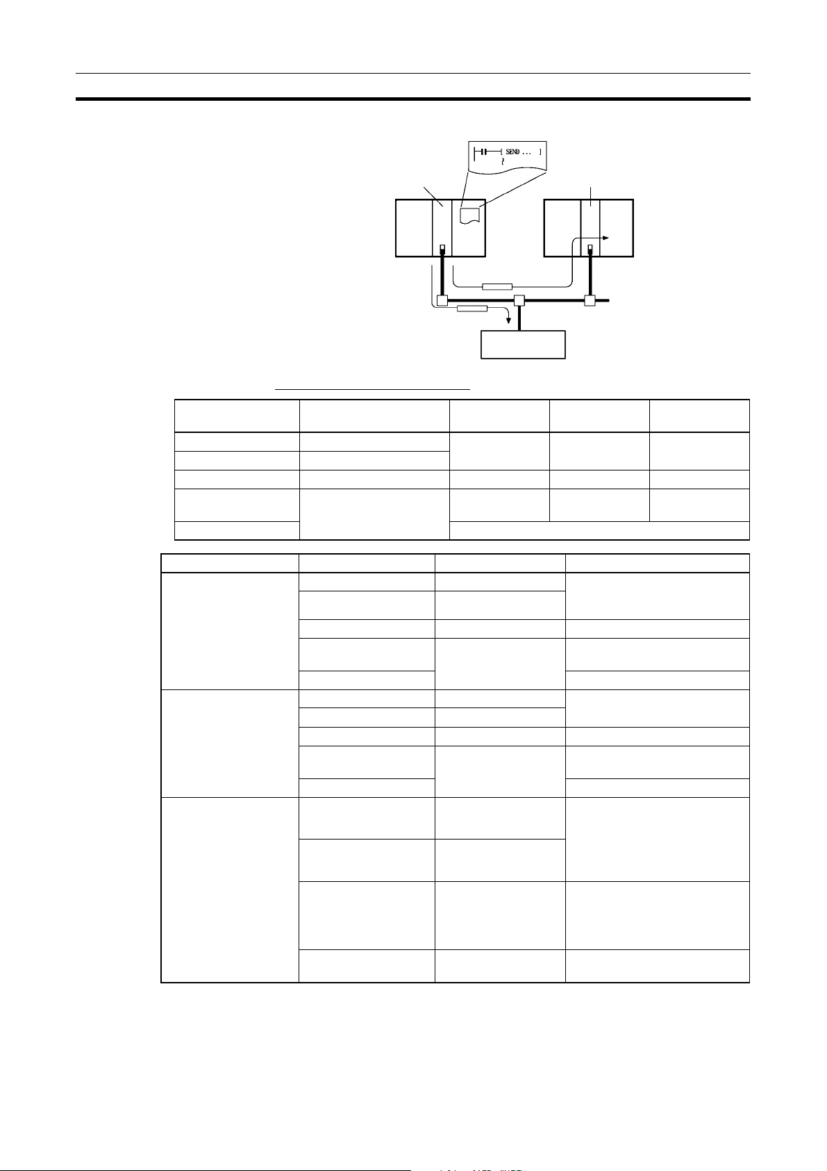
Message Communications
Master Master
RS-232C
Interface Unit
Communications Instructions
Master Unit model Send Receive FINS
commands
CS Series CS1W-DRM21 SEND(192) RECV(193) CMND(194)
CJ Series CJ1W-DRM21
CVM1, CV Series CVM1-DRM21-V1 SEND(192) RECV(193) CMND(194)
CS Series,
C200HX/HG/HE
C200HS ---
C200HW-DRM21-V1 None None IOWR
Item Master model Model Capacity
Max. No. of nodes per
Master for message
communications using
FINS commands
Max. No. of nodes per
Master for message
communications using
explicit messages
Max. message length CS Series CS1W-DRM21 SEND(192): 267 words
CS Series CS1W-DRM21 62 nodes
CJ Series CJ1W-DRM21
CVM1, CV Series CVM1-DRM21-V1 8 nodes
CS Series,
C200HX/HG/HE
C200HS Not supported
CS Series CS1W-DRM21 63 nodes
CJ Series CJ1W-DRM21
CVM1, CV Series CVM1-DRM21-V1 63 nodes
CS Series, C200HX/
HG/HE
C200HS Not supported
CJ Series CJ1W-DRM21
CVM1, CV Series CVM1-DRM21-V1 SEND(192): 76 words
CS Series,
C200HX/HG/HE
C200HW-DRM21-V1 8 nodes
C200HW-DRM21-V1 63 nodes
C200HW-DRM21-V1 IOWR(223): 160 bytes (start-
(Node address 0 cannot be
used in FINS communications.)
RECV(193): 269 words
CMND(194): 542 bytes (start-
ing with command code)
RECV(193): 78 words
CMND(194): 160 bytes
(starting with command code)
ing with command code)
Note FINS message communications are supported between any two PCs with a
CS/CJ-series DeviceNet Unit (CS1W-DRM21/CJ1W-DRM21). They are not
supported for PCs with a C200H DeviceNet Master Unit (C200HW-DRM21-
8
Page 24
Overview of DeviceNet Section 1-1
V1) or a CVM1/CV-series DeviceNet Master Unit (CVM1-DRM21-V1). Refer
to 6-3 Using FINS Mes s age Communications for details.
Communications Software Switches and Communications Status
Dedicated words in the CPU Unit are allocated for DeviceNet communications
software switches and status.
Master
Software
switches
Status area
Control scan list registration/clearing, remote I/O
communications start/stop, and other parameters
Enables monitoring communications errors, communications
status of Masters, registered Slave data, normal Slave data,
etc.
1-1-3 Masters
PC Model Mountable position Master/Slave
function
CS Series CS1W-DRM21
CJ Series CJ1W-DRM21 CPU Rack or Expansion
CVM1/CV Series CVM1-DRM21-V1
CS Series C200HW-DRM21-V1
C200HX/HG/HE 10 or 16
C200HS 10
DeviceNet Unit
DeviceNet Master
Unit
DeviceNet Master
Unit
CPU or Expansion CPU
Rack (Classified as CPU
Bus Units)
Rack (Classified as CPU
Bus Units)
CPU or Expansion CPU
Rack (Classified as CPU
Bus Units)
CPU Rack or Expansion
I/O Rack (Classified as
Special I/O Units)
Master and Slave 16
Master only 16 1
Maximum number of
Configurator
16
mountable units
With
Without
Configurator
1-1-4 Types of Slave
The following classifications are used for DeviceNet Slaves.
• General-purpose Slaves:
Slave with I/O functions for I/O that uses an ordinary connector connected
to a communications cable.
• Environment-resistant Slaves:
Slave with I/O functions for I/O that uses a round, waterproof connector
connected to a communications cable.
• Special Slaves:
Slave with functions not related to I/O (e.g., message communications) for
I/O that uses an ordinary connector connected to a communications
cable.
9
Page 25
Overview of DeviceNet Section 1-1
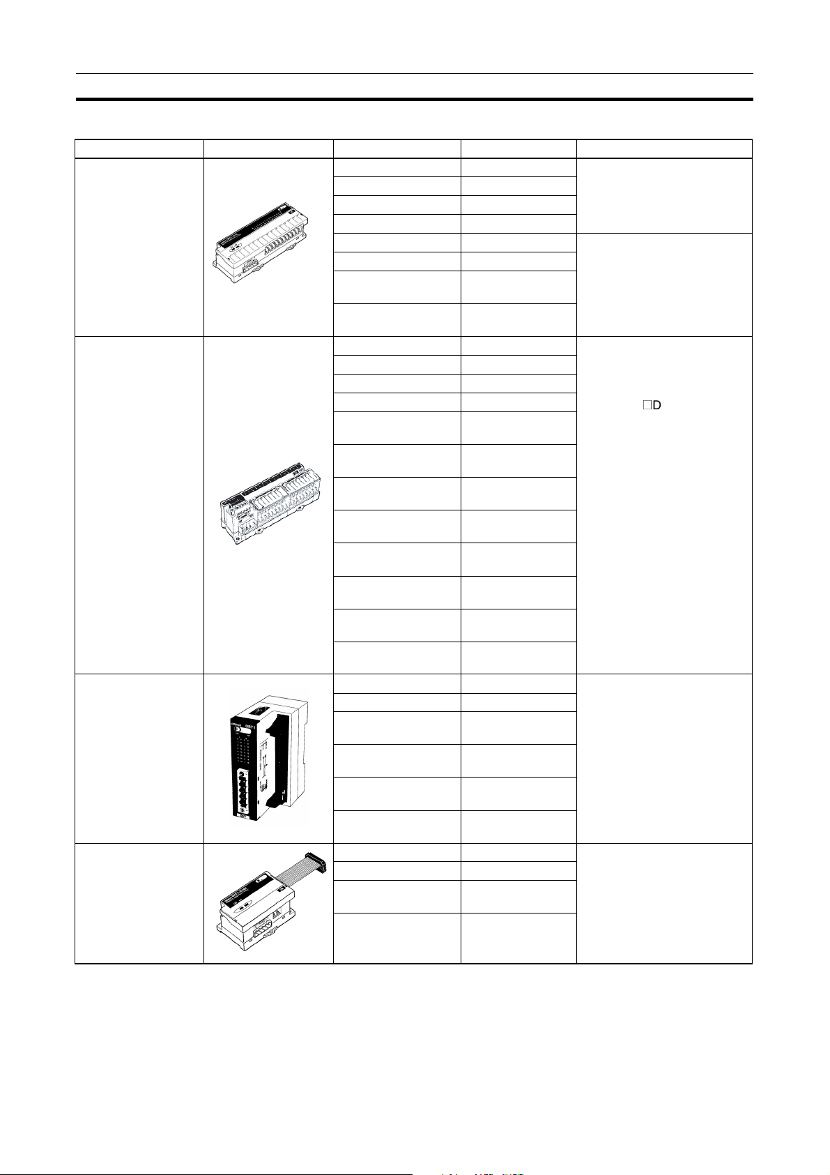
General-purpose Slaves (Communications Cable: Normal Square Connectors)
Name Appearance I/O points Model number Remarks
Remote I/O Terminals
with Transistors
Remote I/O Terminals
with Transistors and
3-tier Terminal Block
Remote I/O Terminals
with Transistors and
Connectors
Remote Adapters 16 input points (NPN) DRT1-ID16X Compact (85 x 50 x 40 mm W
8 input points (NPN) DRT1-ID08 --8 input points (PNP) DRT1-ID08-1
16 input points (NPN) DRT1-ID16
16 input points (PNP) DRT1-ID16-1
8 output points (NPN) DRT1-OD08 --8 output points (PNP) DRT1-OD08-1
16 output points
(NPN)
16 output points
(PNP)
16 input points (NPN) DRT1-ID16T Simple wiring (not necessary
16 input points (PNP) DRT1-ID16T-1
16 input points (NPN) DRT1-ID16TA
16 input points (PNP) DRT1-ID16TA-1
16 output points
(NPN)
16 output points
(PNP)
16 output points
(NPN)
16 output points
(PNP)
8 input points+8 out-
put points (NPN)
8 input points+8 out-
put points (PNP)
8 input points+8 out-
put points (NPN)
8 input points+8 out-
put points (PNP)
32 input points (NPN) DRT1-ID32ML Compact (35 x 60 x 80 mm
32 input points (PNP) DRT1-ID32ML-1
32 output points
(NPN)
32 output points
(PNP)
16 input points+16
output points (NPN)
16 input points+16
output points (PNP)
16 input points (PNP) DRT1-ID16X-1
16 output points
(NPN)
16 output points
(PNP)
DRT1-OD16
DRT1-OD16-1
DRT1-OD16T
DRT1-OD16T-1
DRT1-OD16TA
DRT1-OD16TA-1
DRT1-MD16T
DRT1-MD16T-1
DRT1-MD16TA
DRT1-MD16TA-1
DRT1-OD32ML
DRT1-OD32ML-1
DRT1-MD32ML
DRT1-MD32ML-1
DRT1-OD16X
DRT1-OD16X-1
to tighten multiple wires
together and wiring locations
are easy to understand)
@
The DRT1not need a separate power
supply for internal circuits
(uses the communications
power supply).
(W x D x H))
Connects to a Relay Terminal
through a MIL cable.
Does not need a separate
power supply for internal circuits (uses the communications power supply).
x D x H)
Connects to a G70D Relay
terminal and can be used for a
relay output or a power MOSFET relay output.
D16TA(-1) does
10
Page 26
Overview of DeviceNet Section 1-1
Name Appearance I/O points Model number Remarks
Sensor Terminals 16 input points (NPN) DRT1-HD16S Connected to photoelectric
and proximity sensors with
connectors
Temperature Input
Terminals
Analog Input Terminals
Analog Output Terminals
8 input/8 output
points (PNP)
4 thermocouple input
points (4 words)
4 temperature resistance thermometer
input points (4 words)
4 input points
(4 words) or 2 input
points (2 words)
4 input points
(4 words)
2 output points
(2 words)
DRT1-ND16S
DRT1-TS04T Thermocouple inputs
Temperature resistance thermometer inputs
DRT1-TS04P
DRT1-AD04 1 to 5 V, 0 to 5 V, 0 to 10 V,
–10 to +10 V, 0 to 20 mA, or 4
to 20 mA input (switchable)
Resolution: 1/6,000
DRT1-AD04H 1 to 5 V, 0 to 5 V, 0 to 10 V, 0
to 20 mA, or 4 to 20 mA input
(switchable)
Resolution: 1/30,000
DRT1-DA02 1 to 5 V, 0 to 10 V, –10 to
+10 V, 0 to 20 mA, or 4 to
20 mA output (switchable)
Resolution: 1/6,000
CQM1 I/O Link Unit 16 internal inputs/
CPM2A/CPM1A
I/O Link Unit
16 internal outputs
(between CQM1 and
Master)
32 internal inputs/
32 internal outputs
(between CPM2A/
CPM1A and Master)
Note For details on Slaves, refer to the DeviceNet (CompoBus/D) Slaves Operation
Manual (W347).
CQM1-DRT21 Remote I/O communications
between PCs
CPM1A-DRT21 Remote I/O communications
between PCs
11
Page 27
Overview of DeviceNet Section 1-1
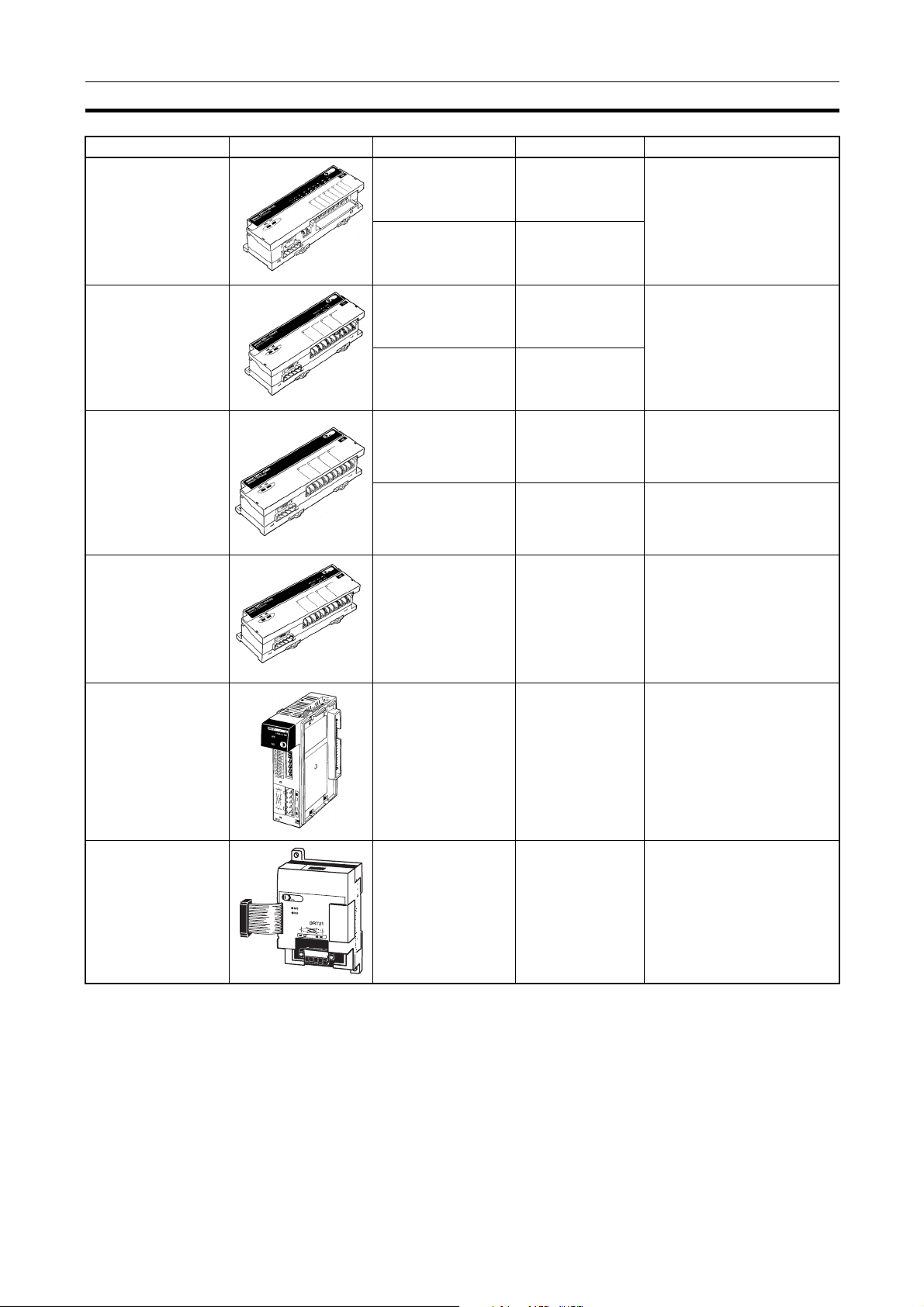
Waterproof and Environment-resistant Slaves (Communications Cable: Round Connectors)
Name Appearance I/O points Model number Remarks
Waterproof Terminals 4 input points (NPN) DRT1-ID04CL Dust and drip-proof structure
for environmental resistance
(IP 67)
XS2 Series connector system
eliminates the need for tools
for sensor, valve or other connections.
structure for environmental
resistance (IP 66)
XS2 Series connector system
eliminates the need for tools
for sensor, valve or other connections.
branches.
XS2 Series connector system
eliminates the need for tools.
Dust and drip-proof structure
for environmental resistance
(IP 66)
Environment-resistant Terminals
B7AC Interface Terminal
4 input points (PNP) DRT1-ID04CL-1
8 input points (NPN) DRT1-ID08CL
8 input points (PNP) DRT1-ID08CL-1
4 output points (NPN) DRT1-OD04CL
4 output points (PNP) DRT1-OD04CL-1
8 output points (NPN) DRT1-OD08CL
8 output points (PNP) DRT1-OD08CL-1
8 input points (NPN) DRT1-ID08C Spatter, dust and drip-proof
8 output points (NPN) DRT1-OD08C
16 input points (NPN) DRT1-HD16C
16 input points (PNP) DRT1-HD16C-1
16 output points
(NPN)
16 output points
(PNP)
8 input points+8 out-
put points (NPN)
8 input points+8 out-
put points (PNP)
10 input points x 3 DRT1-B7AC Splits 1 B7AC Unit into 3
DRT1-WD16C
DRT1-WD16C-1
DRT1-MD16C
DRT1-MD16C-1
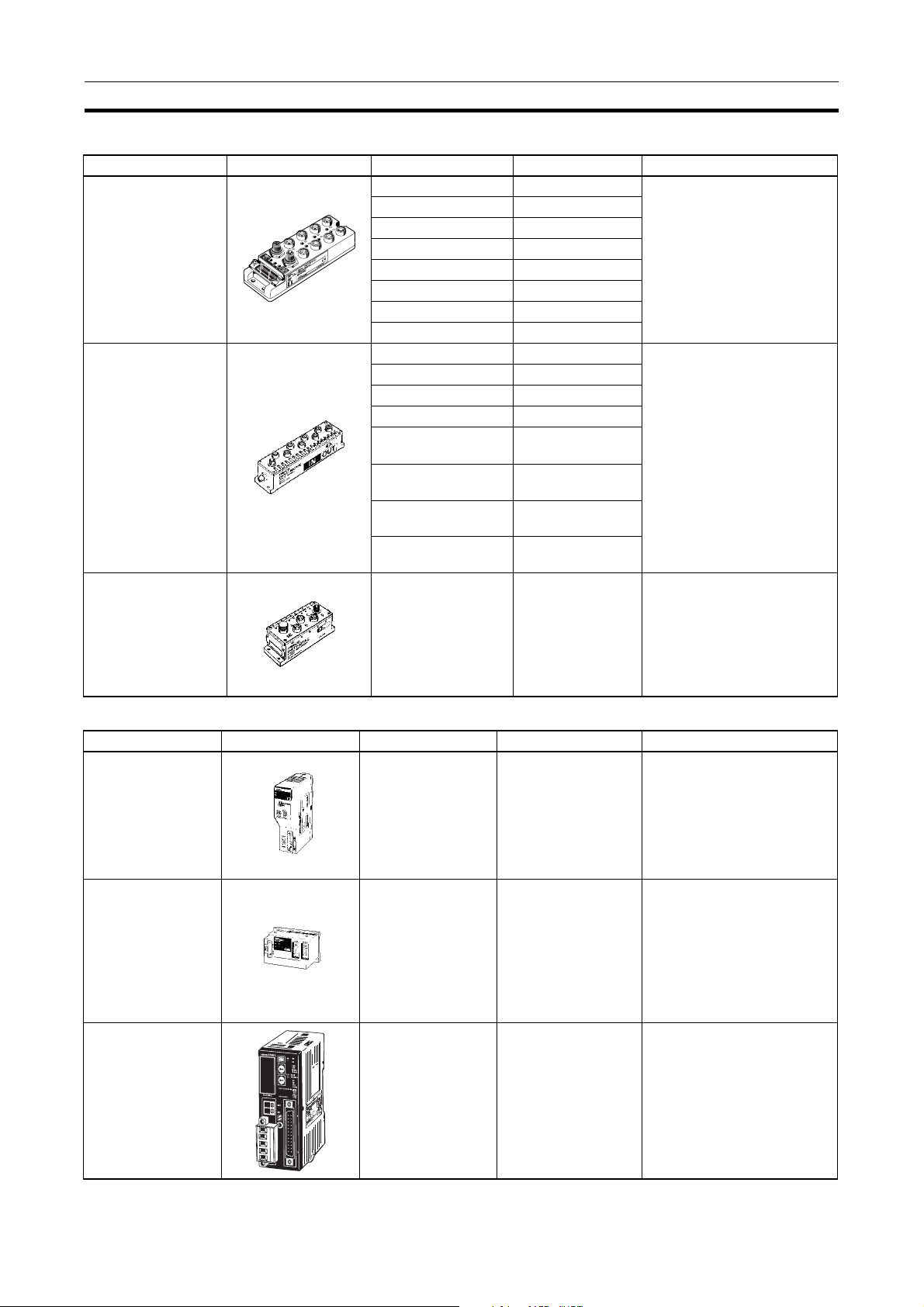
Special Slaves (Communications Cable: Normal Square Connectors)
Name Appearance I/O points Model number Remarks
C200H I/O Link Unit 512 inputs max.
(32 words)
512 outputs max.
(32 words)
RS-232C Unit 16 inputs (1 word) DRT1-232C2 Two RS-232C ports mounted
Programmable
Slaves
512 inputs max.
(32 words)
512 outputs max.
(32 words)
C200HW-DRT21 Supports remote I/O and
message communications
between PCs.
Max. I/O area: 512 input
points and 52 output points
Any I/O words can be allocated.
Data sent and received by
explicit message (151 bytes
max.)
Executes settings and control
through explicit messages.
Reflects RS-232C port status
in the input.
CPM2C-S100C-DRT
CPM2C-S110C-DRT
Controller that enables com-
munications with CompoBus/
S Master.
Enables message communi-
cations using explicit mes-
sages.
12
Page 28

Overview of DeviceNet Section 1-1
MULTIPLE I/O TERMINAL Units
Unit I/O
points
Communications Unit None Two sta-
Basic I/O
Units
Transistor
Input Units
Transistor
Output
Units
Relay Output Units
16 input
points
16 input
points
16 input
points
16 input
points
32 input
points
16 output
points
16 output
points
16 output
points
16 output
points
32 output
points
16 output
points
8 output
points
Words allocated
in PC memory
Input Output
tus
words
1 word 0 words M3 terminal
1 word 0 words Connector
1 word 0 words Connector
1 word 0 words Connector
2 words 0 words High-den-
0 words 1 word M3 terminal
0 words 1 word Connector
0 words 1 word Connector
0 words 1 word Connector
0 words 2 words High-den-
0 words 1 word M3 terminal
0 words 1 word GT1-ROP08 ---
I/O connec-
tions
0 words None 24 VDC
block
(made by
MOLEX)
(made by
FUJITSU)
(D-sub, 25
pin)
sity connector (made by
FUJITSU)
block
(made by
MOLEX)
(made by
FUJITSU)
(D-sub, 25
pin)
sity connector (made by
FUJITSU)
block
Unit
power
supply
volta ge
(supplied
from outside)
Installa-
tion
DIN track DRT1-COM ---
Model
number
GT1-ID16 NPN
GT1-ID16-1 PNP
GT1-ID16MX NPN
GT1-ID16MX-1 PNP
GT1-ID16ML NPN
GT1-ID16ML-1 PNP
GT1-ID16DS NPN
GT1-ID16DS-1 PNP
GT1-ID32ML NPN
GT1-ID32ML-1 PNP
GT1-OD16 NPN
GT1-OD16-1 PNP
GT1-OD16MX NPN
GT1-OD16MX-1 PNP
GT1-OD16ML NPN
GT1-OD16ML-1 PNP
GT1-OD16DS NPN
GT1-OD16DS-1 PNP
GT1-OD32ML NPN
GT1-OD32ML-1 PNP
GT1-ROS16 ---
Remarks
13
Page 29
Overview of DeviceNet Section 1-1
Special
I/O Units
(See
note.)
Unit I/O
points
Analog
Input Units
Analog
Output
Units
Temperature Input
Unit
Counter
Unit
4 inputs 4 words 0 words M3 terminal
8 inputs 8 words 0 words Connector
4 outputs
4 outputs
4 inputs 4 or 8
4 inputs 0 words M3 terminal
1 input 3 words 3 words M3 terminal
Words allocated
in PC memory
Input Output
0 words 4 words M3 terminal
0 words 4 words Connector
0 words M3 terminal
words
(varies
with
data format)
I/O connec-
tions
block
(made by
MOLEX)
block
(made by
MOLEX)
block
block
block
Unit
power
supply
volta ge
24 VDC
(supplied
from outside)
Installa-
tion
DIN track GT1-AD04 Inputs:
Model
number
GT1-AD08MX
GT1-DA04 Outputs:
GT1-DA04MX Outputs:
GT1-TS04T Sensor
GT1-TS04P Sensor
GT1-CT01 1 external
Remarks
4 to 20 mA,
0 to 20 mA,
0 to 5 V,
1 to 5 V,
0 to 10 V,
–10 to 10 V
4 to 20 mA
0 to 5 V,
1 to 5 V,
0 to 10 V,
–10 to 10 V
0 to 5 V,
1 to 5 V,
0 to 10 V,
–10 to 10 V
types: R, S,
K, J, T, B, L
types:
Pt100,
JPt100
input
2 external
outputs
Note The front-panel indicators and other parts of Analog Input Units, Analog Out-
put Units, and Counter Units differ from those of other I/O Units. These Units
belong to a group called Special I/O Units.
One I/O Unit Connecting Cable (cable length 40 mm) is included with each I/O
Unit. One end connector is attached to the Communications Unit.
I/O Unit Connecting Cables with a cable lengths of 0.1, 0.3, 0.4, 0.6, and 1 m
(GCN1-010/030/040/060/100) are sold separately (see below).
Length
Note For details on MULTIPLE I/O TERMINAL Units, refer to the DeviceNet (Com-
poBus/D) MULTIPLE I/O TERMINAL Operation Manual (W348).
14
Page 30

DeviceNet Unit Features Section 1-2
f
1-1-5 DeviceNet Configurator
Use version 2 of the DeviceNet Configurator for the CS1W-DRM21/CJ1WDRM21 DeviceNet Unit. Earlier versions of the DeviceNet Configurator do not
support the CS1W-DRM21 DeviceNet Unit.
Product
name
DeviceNet
Configurator
(Ver. 2)
Model Components Network connection
WS02-CFDC1-E Installation disk
(CD-ROM)
to computer
Any of the following:
• Serial connection
• PCMCIA Card
• ISA Board
(See the table below.)
Applicable
computer
IBM PC/AT or
compatible
OS
Windows 95, 98,
Me, NT4.0, or
2000
Note The following Boards and Cards can be used.
Model Components Applicable
3G8F5-DRM21 Dedicated ISA Board with
DeviceNet Configurator (Ver. 2)
3G8E2-DRM21 Dedicated PCMCIA Card with
DeviceNet Configurator (Ver. 2)
computer
IBM PC/AT or
compatible
Windows 95, 98, or
NT4.0
Windows 95 or 98
OS
Note Use DeviceNet Configurator version 2.10 or later for the CJ1W-DRM21.
1-2 DeviceNet Unit Features
The following are features of the CS-series and CJ-series DeviceNet Units
(CS1W-DRM21 and CJ1W-DRM21).
Multi-vendor Network Devices made by other companies (masters or slaves) can be connected to
DeviceNet because it conforms to open field network specifications. By using
a combination of valves, sensors, and other DeviceNet products, the network
can be adapted to various field-level applications.
Simultaneous Remote I/O
Communications and
Messaging Services
Note Refer to SECTION 4 Remote I/O Master Communications for details on
Remote I/O communications that constantly transfer I/O between a DeviceNet
Unit and slaves as well as message communications where the DeviceNet
Unit sends and receives data as needed can both be executed simultaneously. When a DeviceNet network is constructed, this feature ensures the
network will be able to handle applications that require the free flow back and
forth of bit data and message data. FINS commands can be executed along
with DeviceNet explicit messages in message communications.
Remote I/O Communications
CS/C J-series DeviceNe t
Unit (master)
Remote I/O (master)
unction
Slave
DeviceNet
Slave
Slave
remote I/O communications.
15
Page 31

DeviceNet Unit Features Section 1-2
Explicit Message Communications
CS/CJ-series
DeviceNet Unit
Explicit message
DeviceNet
RS-232C
Slave
RS-232C
Slave
CS/CJ-series
DeviceNet Unit
Note Refer to 6-4 Sending Explicit Messages for details on remote I/O communica-
tions.
FINS Message Communications
CS/CJ-series
DeviceNet Unit
FINS message
DeviceNet
Slave
Slave
CS/CJ-series
DeviceNet Unit
Note Refer to 6-3 Using FINS Message Communications for details on FINS com-
munications.
User-set allocations
without the Configurator
With CS/CJ-series DeviceNet Units, remote I/O communications can be allocated in any area without the Configurator simply by using DM Area settings.
If the Configurator is used, it allows you to change the node address order for
more flexible I/O allocations. This feature ensures the proper I/O allocations
for any application and it makes effective use of PC memory by simplifying
programming.
Note Refer to 4-4 User-set Allocations for details.
Slave Functions CS/CJ-series DeviceNet Units can be used as both masters and slaves, and
master and slave communications can be executed either separately or simul-
16
Page 32

DeviceNet Unit Features Section 1-2
taneously. A Unit that is used as a slave supports fixed and user-set allocations. The maximum I/O for the slave function is 100 words.
CS/CJ-series DeviceNet Unit
(Master)
Master PC
DeviceNet
Configurator Connection
through a Serial Line
CS/CJ-series
DeviceNet Unit
Slave PC
64 nodes max.
(Slave)
Note Refer to SECTION 5 Remote I/O Slave Communications for details.
The Configurator can also be connected either as a DeviceNet node or to a
serial port on a CPU Unit or a Serial Communication Unit/Board.
CS/CJ-series DeviceNet Unit
(Master)
CPU Unit
Serial connection
(Host Link or Peripheral Bus)
DeviceNet
Configurator
Scan list registration
17
Page 33

DeviceNet Unit Features Section 1-2
CX-Programmer
Programming and
Monitoring of DeviceNet
Slave PCs (Ver. 2.1 or
Later)
CS/CJ-series DeviceNet
Unit (master)
CX-Programmer
CX-Programmer Ver. 2.1 connected to a serial communications port on a
DeviceNet PC can be used to remotely program and monitor other DeviceNet
PCs (i.e., PCs with a CS/CJ-series DeviceNet Unit or a Programmable Slave).
CX-Programmer
Serial line (Host Link
or peripheral bus)
DeviceNet
Programmable
Slave
CS/CJ-series
Ethernet Unit
CS/CJ-series DeviceNet
Unit (master)
CS/CJ-series DeviceNet
Unit (master)
Ethernet
DeviceNet
Programmable
Slave
CS/CJ-series DeviceNet
Unit (master)
Note Refer to 7-1 Connecting to the C X - Programmer via the DeviceNet for details.
Inter-network Connections FINS messages can be sent back and forth between DeviceNet and other
networks (e.g., Controller Link, SYSMAC LINK, and Ethernet). This feature
enables seamless message communications between all types of networks,
including DeviceNet.
Controller Link Unit
Controller Link Unit
Controller Link
CS/CJ-series DeviceNet Unit
FINS message
DeviceNet
CS/CJ-series
DeviceNet Unit
18
Note Refer to 6-3 Using FINS Message Communications for details.
Page 34

DeviceNet Unit Features Section 1-2
Multiple PCs in a Single
Network
CS/CJ-series DeviceNet Unit
(Master)
Multiple DeviceNet Units
on a Single PC
CS/CJ-series DeviceNet Unit
(master) (See note 1.)
Multiple DeviceNet Units can be connected in a single network for message
communications between PCs as well as for remote I/O communications
between PCs and slaves in multiple groups. This feature allows a DeviceNet
to be used as a common bus that can integrate all types of control with less
wiring.
Master PC
Remote I/O
DeviceNet
CS/CJ-series
DeviceNet Unit
(Slave)
Slave PC
CS/CJ-series
DeviceNet Unit
Remote I/O
(Master)
Master PC
Note Refer to 4-1 Master Remote I/O Communications for details.
Up to 16 CS/CJ-series DeviceNet Units can be mounted to a single PC. This
feature enables greater DeviceNet remote I/O control capacity and ensures
that DeviceNet can easily handle line expansion as well as other applications.
CS/CJ-series DeviceNet Unit
(master)
DeviceNet
Note 1. Multiple Units can be mounted without the Configurator.
DeviceNet Unit Setup Files
(Memory Card Backup)
DeviceNet
DeviceNet
CS/CJ-series DeviceNet Unit
(slave) (See note 2.)
CS/CJ-series DeviceNet Unit
(master) (See note 1.)
DeviceNet
DeviceNet
2. DeviceNet Units set as both slaves and/or masters can be mounted at the
same time.
3. Refer to 4-1 Master Remote I/O Communications for details.
Setup data (e.g., scan lists) in a DeviceNet Unit can be written as a file to the
Memory Card mounted in a CPU Unit. This feature greatly simplifies
DeviceNet Unit replacement. A DeviceNet Unit device parameter file (same as
data setup file) that is prepared offline using the Configurator can be saved on
a Memory Card, and setup data from the Memory Card can be downloaded to
19
Page 35

DeviceNet Unit Features Section 1-2
a DeviceNet Unit. (See Appendix D Memory Card Backup Function for more
details.)
Note Refer to 7-2 Memory Card Backup Functions for details.
Various Connection
Methods
Maximum Network Length
of 500 m
High-speed
Communications
Compatibility with Slow
Slaves
CS/CJ-series DeviceNet Unit
CPU Unit
Memory Card
File save
File load
Loads setup data to a DeviceNet Unit using a
software switch in CIO Area of the CPU Unit.
Configurator
Normal multi-drop, T-branch multi-drop (with up to three branches), and daisychain line connections are available. These methods can be combined to construct a flexible system that suits the floor layout.
A network can connect up to 63 Slaves and can handle remote I/O communications of up to 2,000 byes (16,000 points without the Configurator) per
DeviceNet Unit. A maximum network length of 500 m is possible with a baud
rate of125 Kbps using thick cable.
High-speed communications are possible at up to 500 Kbps for a trunk line
length of 100 m.
The communications cycle time can be set even without the Configurator so
slaves with slow response times can be used.
A Wide Variety of Slaves A wide variety of I/O devices, like Remote I/O Terminals, Environment-resis-
tant Terminals, Remote Adapters, Sensor Terminals, Temperature Input Terminals, CQM1 I/O Link Units, Analog I/O Terminals, C200H I/O Link Units,
RS-232C Units, MULTIPLE I/O TERMINALs, Temperature Adjusters, Inverters, and Intelligent Plugs can be used as slaves.
20
Page 36

Specifications Section 1-3
1-3 Specifications
1-3-1 DeviceNet Unit
Model
Applicable PC Unit classification Types of communications Model number
CS Series CPU Bus Unit • Remote I/O communications master (fixed
or user-set allocations)
CJ Series CJ1W-DRM21
• Remote I/O communications slave (fixed
or user-set allocations)
• Message communications
General Specifications General specifications of the CS/CJ-series DeviceNet Unit conform to the
general specifications for the SYSMAC CS/CJ-series CPU Units.
Functional and Performance Specifications
Item Specification
DeviceNet Unit model CS1W-DRM21 CJ1W-DRM21
Applicable PC CS Series CJ Series
Unit classification CPU Bus Unit
Applicable unit numbers 0 to F
Mounting position CPU Rack, CS Expansion Rack
(Cannot be mounted to a C200H
Expansion I/O Rack or SYSMAC
BUS Slave Rack.)
No. of Masters that can
be mounted
No. of Slaves
that can be
mounted
No. of Units that can be connected per network 64 Units max.
Fixed allocations 3 Units max. (Unique words must be allocated using the Allo-
cated CIO Area Words Software Switches.)
User-set allocations By allocated
DM Area words
By Configurator 16 Units max. (Unique words must be allocated using the Config-
Fixed allocations 3 Units max. (Unique words must be allocated using the Allo-
User-set allocations By allocated
DM Area words
By Configurator 16 Units max. (Unique words must be allocated using the Config-
16 Units max. (Unique words must be allocated using the user
setup tables in the allocated DM Area words.)
urator.)
cated CIO Area Words Software Switches)
16 Units max. (Unique words must be allocated using the user
setup tables in the allocated DM Area words.)
urator.)
CS1W-DRM21
CPU Rack or Expansion
Rack
21
Page 37

Specifications Section 1-3
Item Specification
Words allocated in the
CPU Unit
DeviceNet
remote I/O
communications
CIO Area words allocated for the CPU
Bus Unit
DM Area words allocated for the CPU
Bus Unit
Other I/O memory Set the allocation size table for all slaves in any area when
When
used as
a Master
When
used as
a Slave
Fixed allocations
User-set allocations
Fixed allocations
User-set allocations
Fixed words in the CS/CJ-series DeviceNet Area in the CIO Area
(any of three settings).
Any I/O memory (Set using the allocated DM Area words or Configurator.)
Fixed words in the CS/CJ-series DeviceNet Area in the CIO Area
(one of three settings).
Any I/O memory words (Set in allocated DM Area words or Configurator.)
25 words/Unit (allocation for one Unit)
CPU Unit to DeviceNet Unit: 9 words for the software switches, 6
words for the status area, 8 words for the registered slaves and
normal slaves tables
100 words/Unit (allocation for one Unit)
Scan List User Setup Table, Slave User Setup Table, Master I/O
Allocation Reference Table, Slave I/O Allocation Reference
Table, Detailed Slave Status Table, etc.
CPU Unit to DeviceNet Unit: Table for communications cycle time
settings
remote I/O communications is set to user-set allocations from the
setting in the allocated DM Area words.
Item Specifications
Supported connections (communications) • Remote I/O communications (master and slave): Master/slave
connection (poll, bit-strobe, COS, cyclic)
• Explicit message and FINS message communications: Explicit
connection
All conform to DeviceNet communications standards.
22
Page 38

Specifications Section 1-3
Item Specifications
Remote I/O
master communications
Slave allocation method Fixed allo-
cations
User-set
allocations
Select one of the following fixed allocation areas using the Fixed
Allocated Area Switches 1, 2, and 3 in the software switches in
the allocated CIO Area words.
Allocated
words
(CIO
Area)
By allocated DM
Area
words
By Configurator
I/O Size Fixed
Alloca-
tion
Area
Setting
1
Output
(OUT)
area
Input (IN)
area
Select one of the above areas using the software
switches. All are fixed at 1 word per node address.
The default setting is Fixed Allocation Area Setting 1.
Set the areas and the first words for the OUT 1 and
IN 1 blocks in the Scan List Setup Table in the allocated DM Area words. Set the allocation size for
each slave using the Allocation Size Setup Table
(any words). Allocations must be in the order of node
addresses.
Allocated
words
Set the areas for the OUT 1/2 and IN 1/2 blocks, the
first words, and the allocation sizes for all slaves
using the Configurator. Blocks can be set for nodes
in any order.
Allocated
words
64 words 3200 to
3263
64 words 3300 to
3363
The input and output areas can be the
following sizes starting from any word in
any of the following areas: CIO Area,
WR Area, HR Area, DM, Area, or EM
Area.
Output
(OUT)
area
Input (IN)
area
The input and output areas can be the
following sizes starting from any word in
any of the following areas: CIO Area,
WR Area, HR Area, DM, Area, or EM
Area.
Output
(OUT)
area
Input (IN)
area
500 words max. × 1 block
500 words max. × 1 block
500 words max. × 2 blocks
500 words max. × 2 blocks
Fixed
Alloca-
tion
Area
Setting
2
3400 to
3463
3500 to
3563
Fixed
Alloca-
tion
Area
Setting
3
3600 to
3663
3700 to
3763
23
Page 39

Specifications Section 1-3
Item Specifications
Remote I/O
master
Max. No. of Slaves connected per DeviceNet Unit
Max. No. of I/O points per
DeviceNet Unit
Max. No. of I/O per Slave
controllable by a DeviceNet
Unit
Fixed allocations 63 nodes
User-set
allocations
Fixed allocations 2,048 pts (64 input words, 64 output words)
User-set
allocations
Fixed allocations 2,048 pts (64 input words, 64 output words)
User-set
allocations
By allocated DM
Area
words
By Configurator
By allocated DM
Area
words
By Configurator
By allocated DM
Area
words
By Configurator
16,000 pts (500 input words x 1 block, 500 output
words x 1 block)
32,000 pts (500 input words x 2 blocks, 500 output
words x 2 blocks)
3,200 pts (100 input words, 100 output words)
3,200 pts (100 input words, 100 output words)
24
Page 40

Specifications Section 1-3
Item Specifications
Remote I/O
slave
Allocation method Fixed allo-
cations
User-set
allocations
Max. No. of I/O points per
DeviceNet Unit slave
Fixed allocations 32 points (1 input word, 1 output word)
User-set
allocations
Select one of the following fixed allocation areas using the Slave
Fixed Allocated Area Switches 1, 2, and 3 in the software
switches in the allocated CIO Area words.
Allocated
words
(CIO
Area)
Note Select one of the preceding areas using the software
switches. All are fixed at 1 word per node address. The
default setting is Fixed Allocation Area Setting 1.
By allocated DM
Area
words
By Configurator
By allocated DM
Area
words
By Configurator
I/O Size Fixed
Alloca-
tion
Area
Setting
1
Output
(OUT)
area to the
slave from
the master
Input
(OUT)
area to the
master
from the
slave
Set the areas, the first words, and slave allocation
size for the OUT 1 and IN 1 blocks (total of 2 blocks)
using the Slave User Allocation Setup Table in the
allocated DM Area words.
Allocated
words
Set the areas for the OUT 1/2 and IN 1/2 blocks, the
first words, and the slave allocation sizes using the
Configurator.
Allocated
words
3,200 pts (100 input words, 100 output words)
4,800 pts (100 input words x 2, 100 output words
x1)
1 word 3370 3570 3770
1 word 3270 3470 3670
The input and output areas can be the
following sizes starting from any word in
any of the following areas: CIO Area,
WR Area, HR Area, DM, Area, or EM
Area.
Output (OUT) area from this
slave
Input (IN) area to this slave 100
The input and output areas can be the
following sizes starting from any word in
any of the following areas: CIO Area,
WR Area, HR Area, DM, Area, or EM
Area.
Output (OUT) area from this
slave
Input (IN) area to this slave 100
Fixed
Alloca-
tion
Area
Setting
2
Fixed
Alloca-
tion
Area
Setting
3
100
words
words
100
words
words
25
Page 41

Specifications Section 1-3
Item Specifications
Default settings • Scan list: Not supported
• Master communications: Supported
• Slave communications: Disabled
• Remote I/O communications: Start
• Master fixed allocations: Fixed Allocation Area Setting 1
• Slave fixed allocations: Fixed Allocation Area Setting 1
Data stored in non-volatile memory (EEPROM) in the
DeviceNet Unit
Applicable connections • The DeviceNet Unit automatically selects the applicable con-
Communications cycle time Uses values calculated using the following equations to derive
Message
communications
Max. No. of nodes for message communications per DeviceNet Unit
Execution commands FINS commands to
Sending and receiving FINS commands
connected through a serial line
Inter–network communications
Same type
of network
Different
type of network
Saves the following data settings (same as the backup file on the
Memory Card).
• Master scan list
• Slave scan list
• Message monitoring timer list (monitoring time for explicit mes-
sage responses)
• Communications time settings
• Master/Slave enabled
nection.
• The user can also specify poll, bit-strobe, COS (change of
state) or cyclic for the applicable connection of each slave using the Configurator. Up to two types of connections can be set
for each Slave (although COS and cyclic cannot be specified simultaneously).
default value.
Example: 16 Input Slaves (16 points each), 16 Output Slaves
(16 points each), and a baud rate of 500 Kbps: 9.3 ms
The user can set a value within a range from 2 to 500 ms. How-
ever, the calculated value is only enabled when the calculated
value from the conditions equation is greater than the setting.
Note Uses the default value calculated using 1 input word and
1 output word even for missing nodes when the scan list
is disabled.
FINS message communications (Node
address 0 cannot be
used in FINS communicatins.)
Send explicit messages
send/receive data
Any FINS commands CMND instruction
Executes FINS commands from a host computer to a PC (to
which a CS/CJ-series DeviceNet Unit is mounted) on DeviceNet
through Host Link connections. A PC can also send unsolicited
FINS commands over DeviceNet to a host computer connected
through Host Link.
Allows transmission across the same type of networks between
DeviceNet networks when multiple Units are mounted (can cross
up to three levels).
Allows transmission across different types of networks between
DeviceNet and other networks (e.g., Controller Link, SYSMAC
LINK and Ethernet) (can cross up to three levels).
62 nodes Note FINS message com-
63 nodes
SEND/RECV instructions
munications using
SEND/RECV are
not supported on
PCs to which a
C200H DeviceNet
Master Unit or a
CVM1/CV
DeviceNet Master
Unit is mounted.
Explicit message
are supported however.
26
Page 42

Specifications Section 1-3
Item Specifications
Other functions
Configurator connection method 1) Serial connection (peripheral bus or Host Link)
Setting section Rotary switches:
Display section Two LED indicators (2 colors): Display Unit and network status.
Front connector One communications connector (communications data: CAN H
Remote programming/monitoring functions
Operation from the Configurator connected through a serial line
Memory Card backup function Allows DeviceNet Unit data settings (scan list, communication
Error history in the DeviceNet Unit Supported. (The history can be accessed up by the Configurator
Communications cycle time setting Supported (in the allocated DM Area words or from the Configu-
Message monitoring timer Sets the response monitoring time (explicit connection opening
COS/cyclic heartbeat timer setting Sets the minimum SEND interval in COS or cyclic connections
Device data check function Performs a comparison check on the following device data when
A CX-Programmer connected to the serial communications port
of a PC to which a CS/CJ-series DeviceNet Unit is mounted can
remotely program and monitor DeviceNet slave PCs with a CS/
CJ-series DeviceNet Unit mounted. Either the peripheral port or
built-in RS-232C port can be used with the Host Link or peripheral bus protocol. (Scheduled for CX-Programmer Ver. 2.1 or
later)
Note 1. Serial ports on a Serial Communications Board/Unit
can be used in addition to the ports on the CPU Unit.
2. Inter-network communications across up to 3 levels is
possible (even over different types of network).
3. This is also possible from a CX-Programmer on network.
Allows all online monitoring and setup functions to be performed
on a master PC on the DeviceNet network from the Configurator
connected through a serial line (scan list registration, communications parameter settings, etc.).
cycle time settings, etc.) to be backed up as a file to a Memory
Card in the CPU Unit. The data settings can also be restored into
the DeviceNet Unit from the Memory Card in the CPU Unit. Setting data can be restored into a DeviceNet Unit simply by carrying the Memory Card to the site if the device parameter file
prepared from the Configurator is saved to Memory Card from a
PC.
or using a FINS command.)
rator).
interval) in the DeviceNet Unit for explicit message communications. Settings can be made separately for all targeted devices
using the Configurator.
for all targeted devices. The setting is made using the Configurator.
slave data registered in the scan list is compared with actual
slave data. The Configurator can be used to set this function for
all targeted Slaves.
Vendor, device type and product code
2) Direct DeviceNet connection through a dedicated Board/Card
The online functions available are the same for both 1) and 2).
Unit No. (hexadecimal x 1), node address (decimal x 2)
Front panel DIP switch: Baud rate, stop or continue communica-
tions when an error occurs
Two-digit 7-segment display: Displays the DeviceNet Unit node
address, error code, and node address where an error occurred.
2 dot LED indicators: Display whether the registration scan list is
enabled or not.
and CAN L, communications power supply: V+, V–, shielded)
Use the XW4B-05C1-H1-D connector provided to connect the
communications cable.
Note Use the XW4B-05C4-T-D connector sold separately for
multi-drop connections.
27
Page 43

Specifications Section 1-3
Item Specifications
Communications power supply voltage 11 to 25 VDC (supplied from the communications connector)
Influence on CPU Unit cycle time 0.7 ms+0.001 x the number of words allocated
Current consumption
CS1W-DRM21:
Communications power supply: 30 mA at 24 VDC, (supplied from
the communications connector)
Internal circuit power supply: 290 mA max. at 5 VDC (supplied
from the Power Supply Unit)
CJ1W-DRM21:
Communications power supply: 18 mA at 24 VDC, (supplied from
the communications connector)
Internal circuit power supply: 290 mA max. at 5 VDC (supplied
from the Power Supply Unit)
External dimensions CS1W-DRM21: 35 x 130 x 101 mm (W x H x D)
CJ1W-DRM21: 31 x 90 x 65 mm (W x H x D)
Weight CS1W-DRM21: 172 g (including the connector provided)
Standard accessories One XW4B-05C1-H1-D connector to connect to a node from a T-
CJ1W-DRM21: 118 g (including the connector provided)
branch Tap.
1-3-2 Comparison between CS1W-DRM21 and CJ1W-DRM21
Only the following items are different between the CS1W-DRM21 and the
CS1W-DRM21. Otherwise, these Units are functionally the same.
Item CS1W-DRM21 CJ1W-DRM21
Consumption current Communications power
supply: 30 mA at 24 VDC
External dimensions 35 x 130 x 101 mm
(W x H x D)
Weight (including connector) 172 g 118 g
Communications power
supply: 18 mA at 24 VDC
31 x 90 x 65 mm
(W x H x D)
28
Page 44

Comparison with Previous Models Section 1-4
1-4 Comparison with Previous Models
The following table provides a comparison between the CS1W-DRM21
DeviceNet Unit and the C200HW-DRM21-V1 DeviceNet Master Unit used in a
CS/CJ-series PC.
Item C200HW-DRM21-V1 CS1W-DRM21/CJ1W-DRM21
Unit classification C200H Special I/O Unit CPU Bus Unit
Mounting position CPU Rack, C200H I/O Expansion Rack, CS-
series Expansion Rack
No. of Masters that can
be mounted
Routing table registration Not necessary When creating a routing table, registration in
Unit No. that can be set 0 to F 0 to F
Masters on a single network Multiple Masters, Configurator required Multiple Masters even without the Configura-
Remote I/O
communications
Message communications Explicit message send, FINS message com-
Registration in the scan list
when using only message
communications
Area used to
exchange
data with the
CPU Unit
(not including remote I/
O allocation)
Fixed allocations
User-set allocations
Master ❍❍
Slave X ❍
Allocated
CIO Area
words
Allocated DM
Area words
Dedicated
DM area
1 Master 3 Masters (Select unique words must be
16 Masters (Configurator required) 16 Masters (even without the Configurator)
munications
Required Not required
2,000 to 2,009 + (10 x unit number) 1,500 to 1,524 + (25 x unit number)
Not used D30000 to D30099 (100 x unit number)
D06032 to D06033 + (2 x unit number) Not used.
CPU Rack, CS/CJ-series Expansion Rack
allocated using the software switches.)
3 Slaves (Select unique words must be allocated using the software switches.)
a local network table is necessary.
tor
Explicit message send, FINS message communications
Note Can send and receive explicit mes-
sages to the PC to which a C200H
DeviceNet Master Unit or CVM1/CV
DeviceNet Master Unit is mounted.
Cannot sent or receive FINS messages.
Note With user-set allocations using the
allocated DM Area words however,
the Allocation Size Setup Table must
be allocated to a position in I/O memory.
29
Page 45

Comparison with Previous Models Section 1-4
Item C200HW-DRM21-V1 CS1W-DRM21/CJ1W-DRM21
Remote I/O
communications Master
Fixed allocations
User-set allocations
C200H DeviceNet words in CIO Area
1,600 points (50 input words, 50 output
words)
Output area: CIO 0050 to CIO 0099
Input area: CIO 0350 to CIO 0399
Node addresses: 0 to 49, node address
order, 1 word/node address
• Slaves with 8 points: Require 1 word even though they are allocated the rightmost byte
(requires 1 node address)
• Slaves with 16 points: Require 1 word (require 1 node address)
• Slaves with over 16 points: Require multiple words (require multiple node addresses)
Set by the Configurator. Set from allocated DM Area words (Master
When using the message communications
function:
1,600 pts max. (800 input words, 800 output
words)
When not using the message communications function:
4,800 pts max. (2,400 input words, 2,400
output words)
The following areas can be set:
CIO: 0000 to 0235, 0300 to 0511
CIO: 1000 to 1063
HR: HR000 to HR099
DM: D00000 to D05999
OUT 1, OUT 2, IN 1, and IN 2, for a total of 4
blocks can be set at any size (total for 1 to 4
blocks) at any position in the allocation
areas given above.
Any node addresses can be set within a
block.
With a total of 4 blocks and a maximum of
100 words per block, the maximum number
of words is 100 using message communications and 300 without using the message
communications.
Maximum of 32 input words, 32 output
words per slave.
There are the following restrictions.
• The bytes 7 to 15 cannot be used for start bytes for slaves with more than 8 points.
• More than one master cannot share a slave.
• Slaves with 8 points: Require the leftmost or rightmost byte (does not require 1 word)
• Slaves with 16 points: Require 1 word
• Slave with over 16 points: Require multiple words (the last byte will be the rightmost byte
with an odd number of bytes)
CS/CJ-series DeviceNet words in CIO Area
2,048 points (64 input words, 64 output
words)
Select one of the following using the software switch.
Output area: (1) CIO 3200 to CIO 3263
(2) CIO 3400 to CIO 3463
(3) CIO 3600 to CIO 3663
Input area: (1) CIO 3300 to CIO 3363
(2) CIO 3500 to CIO 3563
(3) CIO 3700 to CIO 3763
Node addresses: 0 to 63, node address
order, 1 word/node address
User Allocation Setup Table) or the Configurator.
When set from allocated DM Area words:
16,000 pts max. (8,000 input words, 8,000
output words)
When set from the Configurator:
32,000 pts max. (16,000 input words, 16,000
output words)
The following areas can be set:
CIO: 0000 to 6143
WR: W000 to W511
HR: HR000 to HR511 words
DM: D00000 to D32767
EM: E00000 to E32767 (Banks 0 to C supported)
Any position in the allocation areas given
above.
Using allocated DM Area words: Total of two
block, OUT 1 and IN 1.
Using the Configurator : A total of 4 blocks,
OUT 1, OUT 2, IN 1, and IN 2
500 words max. per block
Using allocated DM Area words:
1,000 words total for 2 blocks
Using the Configurator:
2,000 words total for 4 blocks
Using 2 connections:
Maximum of 200 input words, 100 output
words per slave.
Using 1 connection:
Maximum of 100 input words, 100 output
words per slave.
30
Page 46

Comparison with Previous Models Section 1-4
Item C200HW-DRM21-V1 CS1W-DRM21/CJ1W-DRM21
Remote I/O
communications Master
Remote I/O
Slave
Message
communications
Configuration connection method
I/O communications at startup
Max. No. of
slaves connected
Fixed allocations
User-set allocations
Execute commands
Max. No. of
nodes for
message
communications
Gateway
function from
serial communications
Inter-network function
Serial connection
Direct connection to
DeviceNet
With no Configurator (fixed allocations):
50 nodes
With no Configurator (user-set allocations):
63 nodes
No DeviceNet words in CIO Area: 32 points
No Set in the allocated DM Area words or the
Sending/receiving data: No
Any FINS command: IOWR instruction
8 nodes 63 nodes
Not supported Allows the CX-Programmer connected by a
Not supported Supported
Not supported Supported (Peripheral Bus or Host Link con-
Supported Supported
Specifies I/O communications start/stop
after each slave on the scan list starts
(nodes that perform explicit message communications must also be registered in the
scan list).
63 nodes for fixed or user-set allocations
(1 input word, 1 output word)
Select one of the following:
Input area to the Slave:
(1) CIO 3370, (2) CIO 3570, (3) CIO 3770
Output area from the Slave:
(1) CIO 3270, (2) CIO 3470, (3) CIO 3670
Configurator.
The following areas can be set:
CIO: CIO 0000 to CIO 6143
WR: W000 to W511
HR: HR000 to HR511
DM: D00000 to D32767
EM: E00000 to E32767 (Banks 0 to C supported)
Using the allocated DM Area words:
Can create OUT 1 and IN 1 for a total of 2
blocks.
Using the Configurator:
Can create OUT 1, OUT 2, IN 1, and IN 2 for
a total of 4 blocks.
100 words max. per block
Using the allocated DM Area words: 200
words total for 2 blocks
Using the Configurator: 300 words total for 3
blocks
Sending/receiving data: SEND/RECV
instructions
Any FINS command: CMND instruction
serial line to remotely control and monitor a
PC on the DeviceNet (scheduled for Ver.
2.1).
Allows inter-network communications
between DeviceNet and networks like Controller Link and Ethernet (3 levels max.).
nection to a CPU Unit or a Serial Communication Board/Unit)
Sets Master start/stop (using a software
switch or the Configurator).
Performs I/O communications only with
slaves registered in the scan list. (Explicit
message nodes do not have to be registered
in the scan list.)
31
Page 47

Comparison with Previous Models Section 1-4
Item C200HW-DRM21-V1 CS1W-DRM21/CJ1W-DRM21
Starting and stopping remote
communications during I/O
communications
Remote I/O communications
with a communications error
Communications parameters Can be changed (communications cycle time).
Sending explicit messages
to slaves made by another
company
Master error history Yes (Can be read by the Configurator or FINS command.)
Setting communications
cycle time
Monitoring current communi-
cations cycle time
Switch that disables commu-
nications error stoppage
Error with multiple Units
mounted
Error code on
the front
panel 7-segment display
Error with
multiple Units
mounted
PC initialization error
RAM error Display: F5 Changed to H3 (related to the above).
Incorrect
switch setting
Routing table
error
PLC Unit
WDT error
EEPROM
error
Configura-
tion data
error (scan
list SUM
error)
Starts or stops remote I/O communications using the Configurator or the software switch
from a Programming Device.
Sets remote I/O communications start or stop when an error occurs in master communications (set on DIP switch on the front of the Master).
Supported
Supported (by the Configurator) Supported (with or without the Configurator)
Supported
The switch that cancels communications
error stoppage is different from the one that
starts remote I/O communications.
A mounting error occurs with fixed allocations.
Display: E4 No check for multiple mounted Units.
Display: F5 Used more detailed error codes in initializa-
Display: F5 Changed to H5 (related to the above).
Display: E5 Changed to HC (related to the above).
Display: All lit Display: E7 Unit does not reset. Explicit
Display: F8 Stops operation to store the
scan list.
Display: E8 Continues operation in DISABLED mode.
The same software switch is used to cancel
communications error stoppage and to start
remote I/O communications.
An error does not occur even with multiple
Units mounted. Operation will continue even
if the same words are allocated to more than
one Unit.
tion phase. Display: H
server functions run.
Display: E3 Operation continues for error
history only (scan list stored in flash ROM)
Display: F7 Stops remote I/O communica-
tions in Master communications.
@
.
32
Page 48

Outline of the Configurator Section 1-5
1-5 Outline of the Configurator
Allocations for remote I/O communications can be set in any order of node
addresses from the Configurator. Users can also set remote I/O communications connections.
Device (master/slave) registration, I/O allocations, and other operations are
especially easy to perform because of graphic operations, including dragging
and dropping icons.
Any of the following methods can be used to connect the Configurator to
DeviceNet. All the connection methods support the same online connection
functions.
Connection from Dedicated Board/
Card Installed in Computer
Serial Connection from COM
port of Computer
WS02-CFDC1-E
Configurator
ISA Board or PCMCIA Card
DeviceNet Network
The Configurator is treated as a single
DeviceNet node.
CS/CJ-series
DeviceNet Unit
The Configurator is not treated as a
single DeviceNet Node.
1-5-1 Models
Product Model Contents Method of connecting
personal computer to
network
Configurator
@
(Ver. 2.
)
WS02-CFDC1-E Installation disk
(CD-ROM)
Either one of the following
methods
• Serial connection
• Dedicated PCMCIA Card
• Dedicated ISA Board
(see table below)
WS02-CFDC1-E
Configurator
COM port
Peripheral bus or Host Link
Peripheral or RS-232C port of
CPU Unit or RS-232C port of
Communications Board/Unit
DeviceNet network
Personal
computer
IBM PC/AT or
compatible
OS
Windows 95,
98, Me, NT4.0
or 2000
Note Use the following dedicated Boards and Card.
Model Contents Personal
3G8F5-DRM21 Dedicated ISA Board and Configurator (Ver.2)
installation disk
3G8E2-DRM21 Dedicated PCMCIA Card and Configurator (Ver.2)
installation disk
IBM PC/AT or
compatible
The main functions of the Configurator are illustrated below. For further
details, refer to the DeviceNet Configurator Operation Manual (W382).
OS
computer
Windows 95, 98 or NT4.0
Windows 95 or 98
33
Page 49

Outline of the Configurator Section 1-5
Remote I/O master allocations (with creation of a scan list) and
remote I/O slave allocations
Enabling or disabling master or slave function of CS/CJ-series
DeviceNet Unit.
Setting master device parameters except scan list parameters
(i.e., connection settings, device data checks, and
communications cycle time)
Setting other manufacturers' slave and master device
parameters
Displaying a device information list
Monitoring master status, Unit status, Master error logs, and
communications cycle data
Main functions of
Configurator
Setup functions
Monitoring functions
Storage functions
Saving offline device information prepared with master device
parameters or online network device information (Data is saved
as network configuration files.)
Note 1. Master device parameters used in a scan list are created with either of the
following methods.
a) Using the Parameter Wizard
b) Setting all parameters
2. Connect only one Configurator to each Network.
3. Do not use the Configurator in a location with too much electromagnetic
noise, particularly when using a PCMCIA Card. If noise is too extreme, the
computer may run out-of-control, although there will be no negative effects
on the DeviceNet network even if noise causes the computer to run out-ofcontrol.
4. The only DeviceNet masters that can be handled by the Configurator are
OMRON’s CS1W-DRM21, CJ1W-DRM21, CVM1-DRM21-V1, and
C200HW-DRM21-V1.
1-5-2 Configurator Specifications
Item Specification
Operating environment
Network connection method Dedicated Board/Card 3G8F5-DRM21: Dedicated ISA Board
Dedicated
Board/Card
Hardware Personal computer: IBM PC/AT or compatible
OS Windows 95, 98, Me, NT4.0, or 2000
Network status A single node address is used.
Connectable
number of
Boards/Cards
CPU: Pentium 166 MHz or higher (with Windows NT)
Memory: 32 Mbytes
Hard disk: A minimum of 15 Mbytes
3G8E2-DRM21: Dedicated PCMCIA Card
Serial connection (to
DeviceNet network with
gateway)
One/network
• Peripheral or RS-232C port of PC with DeviceNet
Unit mounted.
• RS-232C port of Serial Communications Board/Unit.
Serial communications mode: Peripheral bus or Host
Link
34
Page 50

Outline of the Configurator Section 1-5
Item Specification
Main functions Setup functions Master device parameter settings for OMRON’s Master
• Remote I/O master allocations (with a scan list)
The node address order can be set as desired. Two output blocks and two input
blocks can be allocated. (See note.)
• Remote I/O slave allocations
• Setting master remote I/O communications connections
• Setting slave remote I/O communications connections
• Enabling or disabling device data checks through remote I/O communications
(checks on slave vendor ID, device type, and product code data)
• Setting an explicit message monitor timer list
• Setting a COS/cyclic heart beat timer value
• Setting the communications cycle time
Note 1. A device Parameter Wizard is supported for the Master.
2. Using remote I/O master allocations eliminate restrictions on node
addresses. Furthermore, a number of masters can be mounted to the PC
with no allocation area duplication.
Setting parameters for other manufacturers’ slaves (EDS file required).
Setting node addresses and baud rates
Monitoring functions
Storage functions
Other functions • Reading/writing and preparing EDS files
Files that can be written • Master parameter files (parameters for OMRON Master: 1 file per node)
• Listing information on devices connected to the network (in node address order or
remote I/O configuration order, for example)
• Monitoring Unit status data, Master function status data, and slave function status
data
• Monitoring Master error history
CVM1-DRM21-V1 or C200HW-DRM21-V1: Up to 20 records of time, error code,
and error condition data
CS1W-DRM21: Up to 64 records of time, error code, and error condition data
• Monitoring communication cycle time
Saving offline device information prepared with master device parameters or online
network device information. Such data is saved as network configuration files.
• Checking for duplicate I/O allocations in master parameters
• Printing master/slave device parameters
• Installing Expansion Modules to expand functions
Note Slave communications are saved as well in the master device parameters file
with the DeviceNet Unit.
• Slave device parameter files (parameters for slaves: 1 file per node)
• Network file (all master/slave parameters for masters/slaves in the device list: 1 file/
network)
• EDS file (DeviceNet device definition file: 1 file/device type)
35
Page 51

Basic Operating Procedures Section 1-6
1-6 Basic Operating Procedures
1-6-1 Network Installation Procedure
Note For details on the network installation procedure, refer to the DeviceNet Oper-
ation Manual (
W267). Only a general description is given here.
Check
(1)
(2)
Determine a suitable baud rate for the
system.
Determine the node arrangement, the wiring configuration, and the cable lengths.
A) Restrictions on lengths of trunk lines and
branch lines and total drop line length. (Selection
of thick cables or thin cables)
B) Separation from noise sources.
Do (1) and (2) above meet the
DeviceNet specifications?
Ye s
(3)
Determine the method for providing a
communications power supply.
No
Arrange for the required devices.
(4)
Delivery of devices.
(5)
Installation
1-6-2 Hardware Preparations for Communications
1,2,3... 1. Set the initial settings for the DeviceNet Unit:
Unit No. (UNIT No.)
Node address (NODE ADR)
Baud rate (DIP switches 1 to 2)
Communications continue/stop setting for communications errors (DIP
switch pin 3)(with Master communications)
I/O hold/clear for communications errors (DIP switch pin 4)(with Slave
communications)
2. Set the initial settings for slaves:
36
Page 52

Basic Operating Procedures Section 1-6
Node address (Pins 1 to 6)
Baud rate (Pins 7 and 8)
Etc.
3. Mount the Master and wire the network.
Treat as a CPU Bus Unit.
Can mount to a CPU Rack or Expansion Rack.
With fixed allocations: 3 Units max.
With user-set allocations: 16 Units max.
4. Connect a Programming Device to the PC and turn ON the power supply
to the PC.
5. Generate the I/O tables.
Note 1. A slave may not go online if the communications power supply is turned
ON after the slave is turned ON.
2. The communications power supply and slave power supply, the slave power supply and PC power supply, or all three of these power supplies may
be turned ON simultaneously.
1-6-3 Creating Routing Tables
The DeviceNet Unit functions as a Communications Unit in the same way as a
SYSMAC LINK Unit, Controller Link Unit, and Ethernet Unit.
It is therefore necessary to create routing tables for the communications functions to be used, as shown in the table below.
Mounted Units Using master or
slave functions only
DeviceNet Unit is the
only Communications Unit mounted
Multiple DeviceNet
Units mounted as
Communications
Units
DeviceNet Unit and
other Communications Unit mounted
simultaneously
Not necessary (See note 1.) Local network table (See
Not necessary (See
note 1.)
Local network table necessary (See note 2.)
Note 1. If a local network table already exists in the CPU unit being used, the De-
2. The DeviceNet Unit must be registered in the local network table.
Refer to 6-3 Using FINS Message Communications for information on the
routing tables.
The routing tables are created using CX-Net inside the CX-Programmer.
Refer to the CX-Net Operation Manual (
Note 1. A local network table is sometimes necessary even when the DeviceNet
2. If you prepare a local network table inside the CPU Unit, be sure to register
3. Even if a local network table exists inside the CPU Unit, the 7-segment dis-
Using explicit
message
communications
(not supported
across networks)
Local network table necessary (See note 2.)
Using FINS
message
communications
not across networks
Using FINS message
communications across
networks
note 2.) and relay network
table are necessary.
viceNet Unit must be registered in that table.
WS02-CXPC1-EV
@
)
for details.
Unit is not operating across networks.
the DeviceNet Unit.
play of the DeviceNet Unit may indicate “HC” and FINS message/explicit
37
Page 53

Basic Operating Procedures Section 1-6
message communications may not be possible unless the DeviceNet Unit
is registered in the local network table.
1-6-4 Procedures Prior to Starting Communications
Using the Master Function
To use the master function, the Master Enable Switch (word n, bit 06) must be
turned ON from a Programming Device. Enable master communications
through CS1W-DRM21 properties if you are using a Configurator.
Note 1. Make sure the scan list is enabled when using the master function. This
will allow you to check whether slaves are online or not from the CPU Unit
so that you will be able to determine whether or not the DeviceNet is communicating properly.
2. Remote I/O communications with a specified slave can be turned OFF
(disconnected) by turning ON (1) the corresponding Disconnect/Connect
Switch (words n+6 to n+9) when a slave is replaced or is registered in the
scan list prior to being connected. These switches are cleared when the
power supply is turned OFF, however, so a bit must be turned back ON (1)
from the ladder program when the power turns ON for it to be valid again.
Fixed Allocations
Use the following procedure to use fixed allocations. Refer to 4-3 Fixed Allocations for details on fixed allocations.
1,2,3... 1. Turn ON the communications, slave, and PC power supplies.
Note Turn ON the communications power supply before turning ON the
slave power supplies or the slaves may not go online.
2. Switch the CPU Unit to PROGRAM mode.
3. Check Unit Status 2 (word n+11, bit 03) from a Programming Device connected to the CPU Unit to see if the master function is ON (enabled). If it
is enabled, skip step 4 below and proceed to step 5.
4. If the master function is OFF (disabled), turn ON the Master Enable Switch
(word n, bit 06) from a Programming Device connected to the CPU Unit.
Note Execute this only when master communications are turned OFF. (If
the Master Enable Switch is turned ON when master communications are ON, a Unit error will occur and a C2 error will be displayed
on the 7-segment display on the front panel.)
5. Turn ON the Master Fixed Allocation Area Setting 1 to 3 Switches (word n,
bits 8 to 10). Master remote I/O communications will begin with the scan
list disabled.
6. Turn ON the Scan List Enable Switch (word n, bit 00). Master remote I/O
communications will begin with the scan list enabled.
7. Switch the CPU Unit to RUN mode.
User-set Allocations Using Allocated DM Area Words
Use the following procedure to set allocations using the words allocated to the
Unit in the DM Area. Refer to 4-4 User-set Allocations for details on user-set
allocations.
38
1,2,3... 1. Turn ON the communications, slave, and PC power supplies.
Note Turn ON the communications power supply before turning ON the
slave power supplies or the slaves may not go online.
2. Switch the CPU Unit to PROGRAM mode.
Page 54

Basic Operating Procedures Section 1-6
3. Check Unit Status 2 (word n+11, bit 03) from a Programming Device connected to the CPU Unit to see if the master function is ON (enabled). If it
is enabled, skip step 4 below and proceed to step 5.
4. If the master function is OFF (disabled), turn ON the Master Enable Switch
(word n, bit 06) from a Programming Device connected to the CPU Unit.
Note Execute this only when master communications are turned OFF. (If
the Master Enable Switch is turned ON when master communications are enabled, a Unit error will occur and a C2 error will be displayed on the 7-segment display on the front panel.)
5. Input data in advance into the Master User Allocation Setup Table (words
m+1 to m+6) and the Allocation Size Setup Table (specify the position in
words m+5 and m+6)
6. Turn ON the Master User-set Allocation Switch (word n, bit 11). Master remote I/O communications will begin with the scan list enabled.
7. Switch the CPU Unit to RUN mode.
User-set Allocations Using the Configurator
Use the following procedure to set allocations using the Configurator. Refer to
DeviceNet Configurator Operation Manual for details on Configurator operating procedures
1,2,3... 1. Turn ON the communications, slave, and PC power supplies.
Note Turn ON the communications power supply before turning ON the
slave power supplies or the slaves may not go online.
2. Switch the CPU Unit to PROGRAM mode.
3. Create a network configuration file and device parameters file from the
Configurator. (Enable master communications in CS1W-DRM21 properties at this time.)
4. Download the above files to the devices on the network. Remote I/O communications will begin with the scan list enabled.
5. Switch the CPU Unit to RUN mode.
Using Slave Function
Fixed Allocations
1,2,3... 1. Switch the CPU Unit to PROGRAM mode.
To use the slave function, the Slave Enable Switch (word n+1, bit 06) must be
turned ON from a Programming Device. Enable slave communications
through CS1W-DRM21/CJ1W-DRM21 properties if you are using a Configurator.
With fixed allocations or allocations set in the allocated DM Area words, slave
communications must be disabled prior to area allocation and must be
enabled following area allocation. The order of the procedure is thus Slave
Stop Switch (if slave communications are enabled), area allocation, and Slave
Enable Switch.
Note Slave communications must be disabled prior to area allocation when using
fixed allocations or allocations set in the allocated DM Area words, and the
settings must be read to the Unit when slave communications are enabled.
Allocations will not be valid if slave communications are enabled during area
allocation.
Use the following procedure to use fixed allocations. Refer to 5-2 Fixed Alloca-
tions for details on fixed allocations.
39
Page 55

Basic Operating Procedures Section 1-6
2. Check Unit Status 2 (word n+11, bit 07) from a Programming Device connected to the CPU Unit to see if the slave function is OFF (disabled). If it is
disabled, skip step 3 below and proceed to step 4.
3. If slave communications are enabled, turn ON the Slave Stop Switch (word
n+1, bit 07).
4. Turn ON the Slave Fixed Allocation Area Settings 1 to 3 Switches (word
n+1, bits 8 to 10).
5. Turn ON the Slave Enable Switch (word n+1, bit 06) from a Programming
Device connected to the CPU Unit.
Note Execute this only when slave communications are turned OFF. (If the
Slave Enable Switch is turned ON when slave communications are
enabled, a Unit error will occur and a C2 error will be displayed on
the 7-segment display on the front panel.)
6. Switch the CPU Unit to RUN mode. Slave remote I/O communications will
begin.
User-set Allocations Using Allocated DM Area Words
Use the following procedure to set allocations using the words allocated to the
Unit in the DM Area. Refer to 5-3 User-set Allocations for details on user-set
allocations.
1,2,3... 1. Switch the CPU UNit to PROGRAM mode.
2. Check Unit Status 2 (word n+11, bit 07) from a Programming Device connected to the CPU Unit to see if the slave function is OFF (disabled). If it is
disabled, skip step 3 below and proceed to step 4.
3. If Slave is enabled, turn ON the Slave Stop Switch (word n+1, bit 07).
4. Input data in advance into the Slave User Allocation Setup Table (words
m+8 to m+13).
5. Turn ON the user Slave User-set Allocation Switch (word n+1, bit 11).
6. Turn ON the Slave Enable Switch (word n+1, bit 06) from a Programming
Device connected to the CPU Unit.
Note Execute this only when slave communications are turned OFF. (If the
Slave Enable Switch is turned ON when slave communications are
enabled, a Unit error will occur and a C2 error will be displayed on
the 7-segment display on the front panel.)
7. Switch the CPU Unit to RUN mode. Slave remote I/O communications will
begin.
User-set Allocations Using the Configurator
Use the following procedure to set allocations using the Configurator. Refer to
DeviceNet Configurator Operation Manual for details on Configurator operating procedures
1,2,3... 1. Switch the CPU Unit to PROGRAM mode.
2. Create a device parameter file from the Configurator. (Enable Slave communications in CS1W-DRM21 properties at this time.) Then download the
file to the DeviceNet Unit.
3. Turn ON the Slave Enable Switch (word n+1, bit 06) from a Programming
Device connected to the CPU Unit.
Note Execute this only when slave communications are turned OFF. (If the
Slave Enable Switch is turned ON when slave communications are
enabled, a Unit error will occur and a C2 error will be displayed on
the 7-segment display on the front panel.)
40
Page 56

Basic Operating Procedures Section 1-6
4. Switch the CPU Unit to RUN mode. Slave remote I/O communications will
begin.
Message Communications Only (Neither Master nor Slave Function Used)
The DeviceNet Unit does not have to be registered in the scan list if it is only
used for message communications. Message communications (send and
receive) can be executed with both master and slave communications disabled.
41
Page 57

List of Usage Methods by Purpose Section 1-7
1-7 List of Usage Methods by Purpose
Situation Action Page
Design Allocating any
words for
remote I/O
Using the Unit as a slave Set using the allocated DM Area words. 122
Performing message communi-
cations between PCs to which
DeviceNet Units are mounted
Mounting multiple DeviceNet
Units using master communications to a single PC
Mounting multiple DeviceNet
Units using slave communications to a single PC
Connecting multiple PCs (master
communications) in a network
Connecting a single Master PC
and multiple Slave PCs in a network
Sending DeviceNet explicit messages
Setting the node address for a
DeviceNet Unit
Setting the baud rate for the
DeviceNet Unit
Stopping remote I/O communications for communications errors
Holding OUT data in slave I/O
memory for communications
errors
In order of node
addresses
Not in order of
node
addresses
Set using the allocated DM Area words.
(Master User Allocations Setup Table and Allocation Size Setup Table)
Note Allocations using allocated DM Area words:
Order of node addresses and two blocks,
OUT 1 and IN 1.
Set using the configurator.
Note Allocations using Configurator: Any node
address order and four blocks, OUT 1, IN 1,
OUT 2 and IN 2. Allocation is much easier
using a wizard.
Execute communications instructions from the user
program.
3 Units max. with fixed allocations
16 Units max. with user-set allocations
3 Units max. with fixed allocations
16 Units max. with user-set allocations
Supported by user-set allocations using allocated
DM Area words or user-set allocations using the
Configurator.
Set multiple PCs to Slave mode from the allocated
DM Area words or the Configurator.
Note Up to 64 Units may be on a network.
(Example: 1 Master PC and 63 Slave PCs)
Set the FINS command code to 2801. 138
Set the rotary switches on the front of the
DeviceNet Unit.
Set the DIP switch on the front of the DeviceNet
Unit.
Set the DIP switch on the front of the DeviceNet
Unit.
Set the DIP switch on the front of the DeviceNet
Unit.
108
113
134
92
122
122
122
49
50
51
51
42
Page 58

List of Usage Methods by Purpose Section 1-7
Situation Action Page
Operation Stopping remote I/O communica-
tions with all Slaves
Using a scan list in remote I/O
communications (fixed allocations)
Enabling a scan list in remote I/O
communications (user-set allocations by allocated DM Area
words)
Changing the communications
system configuration
Checking master I/O allocation
status (fixed allocations, user-set
allocations by allocated DM Area
words, user-set allocations by the
Configurator)
Checking to see if all slaves are
registered in the scan list
Checking to see if all slaves are
performing remote I/O communications properly
Checking to see if there is an
error history in the DeviceNet
Unit
Monitoring the error history in the
DeviceNet Unit
Monitoring status of the
DeviceNet Unit
Checking the current communications cycle time
Adjusting the communications
cycle time
Saving all parameters, like scan
list data, for masters and slaves
on the network
Replacing a DeviceNet Unit 1. Insert a Memory Card in the CPU Unit and turn
Stop communications using the Configurator or the
Remote I/O Communications Stop Switch in the
allocated CIO Area words.
Turn ON the Scan List Enable Switch in the allocated CIO Area words.
Set the allocation areas using the allocated DM
Area words, and turn ON the user-set allocations
user setting switch for the allocated CIO Area
words.
Turn ON the Scan List Clear Switch for the allocated CIO Area words, and turn the Scan List
Enable Switch back ON after you change the communications system.
Monitor the Master Status 2 status codes in the
allocated CIO Area words from a Programming
Device.
Check the Registered Slave Table in the allocated
CIO Area words.
Check the Normal Slave Table in the allocated CIO
Area words.
Check the error history (registration yes/no) in the
allocated CIO Area words from a Programming
Device.
Execute the device monitor function from the Configurator (Error History Tab).
Execute the device monitor function from the Configurator (Status and Unit Status Tabs).
Execute the device monitor function from the Configurator (Current Communications Cycle Time
Tab).
Execute the device parameter edit function from
the Configurator (Communications Cycle Time
Tab).
Save the network configuration from the Configurator.
ON the Unit Setup File Backup Switch in the
allocated CIO Area words.
2. Replace the DeviceNet Unit.
3. Turn ON the Unit Setup File List Switch in the
allocated CIO Area words.
4. Turn ON Scan List Clear Switch in the allocated
CIO Area words.
5. Make sure the slave is connected, and then turn
ON the Scan List Enable Switch.
62
61
64
100
75
78
79
73
DeviceNet Configurator Operation Manual
226, 247
43
Page 59

Nomenclature and Installation
This section describes the nomenclature and installation of the DeviceNet Unit.
2-1 Nomenclature and Functions . . . . . . . . . . . . . . . . . . . . . . . . . . . . . . . . . . . . . 46
2-1-1 Nomenclature and Functions . . . . . . . . . . . . . . . . . . . . . . . . . . . . . . 46
2-1-2 Status Indicators: MS and NS. . . . . . . . . . . . . . . . . . . . . . . . . . . . . . 47
2-1-3 Seven-Segment Display . . . . . . . . . . . . . . . . . . . . . . . . . . . . . . . . . . 48
2-1-4 Switch Settings . . . . . . . . . . . . . . . . . . . . . . . . . . . . . . . . . . . . . . . . . 49
2-2 Installing the DeviceNet Unit . . . . . . . . . . . . . . . . . . . . . . . . . . . . . . . . . . . . . 51
2-2-1 System Configuration Precautions . . . . . . . . . . . . . . . . . . . . . . . . . . 51
2-2-2 Mounting. . . . . . . . . . . . . . . . . . . . . . . . . . . . . . . . . . . . . . . . . . . . . . 52
2-2-3 Handling Precautions . . . . . . . . . . . . . . . . . . . . . . . . . . . . . . . . . . . . 53
2-2-4 External Dimensions. . . . . . . . . . . . . . . . . . . . . . . . . . . . . . . . . . . . . 55
SECTION 2
45
Page 60

Nomenclature and Functions Section 2-1
9
8
7
6
5
4
3
2
1
0
9
8
7
6
5
4
3
2
1
0
F
E
D
C
B
A
9
8
7
6
5
4
3
2
1
0
6
7
8
9
3
4
5
6
7
8
9
E
0
0
0
2-1 Nomenclature and Functions
2-1-1 Nomenclature and Functions
CS1W-DRM21
CJ1W-DRM21
DRM21
MS
NS
NODE
ADR
UNIT
No.
X10
1234
ON
CS
Indicators
Unit No. switch
This switch sets the unit number of the DeviceNet Unit
as a one-digit hexadecimal value.
1
0
X10
1
DR0
2
DR1
3
ESTP
HOLD
4
Node address switches
These switches set the node address as a two-digit
decimal value.
DIP switch
The pins have the following functions:
Pins 1 and 2: Baud rate
Pin 3: Continue/Stop communications for error
(when used as a Master)
Pin 4: Hold/clear I/O for communications error
(when used as a Slave)
Communications connector
Connect the Network communications cable to this
connector. The communications power is also
supplied through this connector.
A parallel connector with screws (XW4B-05C1-H1-D)
is provided for node connection.
MS
NS
0
HOLD
4
3
ESTP
2
DR1
1
DR0
NOD
A
x1
x1
ON
ON
1234
Indicators
Unit No. switch
This switch sets the unit number of the DeviceNet Unit as a one-
digit hexadecimal value.
Node address switches
These switches set the node address as a two-digit decimal value.
DIP switch
The pins have the following functions:
Pins 1 and 2: Baud rate
Pin 3: Continue/Stop communications for error (when used as a
Master)
Pin 4: Hold/clear I/O for communications error (when used as a
Slave)
Communications connector
Connect the Network communications cable to this connector. The
communications power is also supplied through this connector.
A parallel connector with screws (XW4B-O5C1-H1-D) is provided
for node connection.
Indicators
The DeviceNet Units are equipped with the following indicators that indicate
the operating status of the node itself and the overall network.
1,2,3... 1. Two status indicators (two-color: Green or red LEDs)
2. A two-digit, 7-segment display
3. Two dot indicators
46
Page 61

Nomenclature and Functions Section 2-1
2. Two-digit, 7-segment display
MS
1. Status indicators
NS
3. Dot indicators
2-1-2 Status Indicators: MS and NS
The MS (Module Status) indicator indicates the status of the node itself and
the NS (Network Status) indicator indicates the status of the network.
The MS and NS indicators can be green or red and they can be OFF, ON, or
flashing (alternating 0.5-s ON and 0.5-s OFF.) The following table shows the
meaning of these indicator conditions.
Indi-
cator
MS Green ON Normal operating status
NS Green ON The Unit is online with the network and remote I/O com-
Color Status Meaning (likely errors)
Communications are being performed normally.
Red ON A non-recoverable, fatal error has occurred.
(Watchdog timer error, memory error, or system error.)
Replace the DeviceNet Unit.
Flashing A recoverable, non-fatal error has occurred. (Structure
error, switch setting error, PC initialization error, PC interface error, or routing table error.)
Correct the error and reset the Unit.
--- OFF Power isn’t being supplied or the Unit is being reset.
munications have been established with a slave registered in the scan list or message communications have
been established.
Flashing The Unit is online with the network, but neither remote I/
O communications nor message communications have
been established. Either the scan list is being read, or
both remote I/O communications and message communications are disabled.
Red ON A fatal communications error has occurred. Network
communications are not possible.
(Node address duplicated or Bus Off error)
Flashing A non-fatal communications error has occurred. (Com-
munications error, setup error, or verification error)
--- OFF The Unit is not online with the network.
(There is no network power supply, the Unit is being
reset, a minor failure, or a sending error has occurred.)
47
Page 62

Nomenclature and Functions Section 2-1
2-1-3 Seven-Segment Display
In addition to the MS and NS indicators, DeviceNet Units have a 2-digit, 7segment display that normally indicates the master node address. When an
error occurs, the display will alternate between the error code and the node
address of the faulty slave.
There are dot indicators at the lower-right corner of each digit. The left dot
indicator shows whether or not the master is operating and whether the scan
list is enabled or disabled. The right dot indicator shows whether or not the
slave is operating.
Normal: Master's node address
Error: Error code and faulty node address
Indicates whether the master is operating or stopped and
whether the scan list is enabled or disabled.
Indicates whether the slave is operating or stopped.
Seven-segment Digits
The following table shows the functions of the 7-segment digits.
Status Display
Remote I/O communications active and
normal
From power ON to completion of node
address check (master function disabled,
slave function disabled, or both disabled)
Remote I/O communications started Flashing (until com-
From completion of the node address
check until the start of remote I/O communications
Error Watchdog timer Not lit
Memory error or
system error
Other errors Alternately displays the error code and
Scan list Reading “--” Flashing
Registered
Displays the master’s node address
(00 to 63)
Error code only Lit
error node address (see diagram below)
Lit
Flashing
munications actually star t)
Flashing
48
Page 63

Nomenclature and Functions Section 2-1
F
E
D
C
B
A
9
8
7
6
5
4
3
2
1
0
9
8
7
6
5
4
3
2
1
0
9
8
7
6
5
4
3
2
1
0
The following diagram shows the alternating error code/ node address display.
Error code
(1 s)
OFF (0.1 s) OFF (0.3 s)
Faulty slave's
node address
(1 s)
OFF (0.3 s)
Master's node
address (1 s)
If there is an error at the DeviceNet Unit.
The master’s error code and master’s node address will be displayed if an
error has occurred at the master.
There is no priority in the error codes; all errors that have occurred will be displayed in order. All error codes begin with letters, so they can be distinguished
from node addresses immediately.
Dot Indicators
The following table shows the functions of the dot indicators.
Indicator Content Display
Left dot Scan list enabled/
Right dot Slave function dis-
disabled, master
function disabled
abled
Error code
(1 s)
OFF (0.1 s)
OFF (0.1 s) OFF (0.3 s)
Faulty slave's
node address
(1 s)
Master's
error code (1 s)
OFF (0.3 s)
ON: Master function disabled
Flashing: Scan list disabled mode
OFF: Scan list enabled mode
ON: Slave function disabled
OFF: Slave operating
2-1-4 Switch Settings
Unit No. Switch Use this switch to set the unit number of the DeviceNet Unit as a CPU Bus
CS1W-DRM21 CJ1W-DRM21
5
4
6
3
7
2
8
1
9
0
A
F
B
E
C
D
Note 1. The unit number is set to 0 at the factory.
Node Address Switches Use these switches to set the node address of the Unit.
CS1W-DRM21 CJ1W-DRM21
3
3
2
X10
2
1
0
9
X10
8
0
1
4
4
1
5
5
0
6
7
6
7
9
8
1
X
X
10
10
Unit. The unit number setting determines the CIO and DM area words allocated to the Unit as software switches and the status area.
Setting method: One-digit hexadecimal
Setting range: 0 to F
2. Any unit number from 0 to F can be set as long as it hasn’t been set on
another CPU Bus Unit connected to the same PC.
3. Use a small flat-blade screwdriver to turn the rotary switches; be careful
not to damage the switch.
4. Always turn OFF the PC before changing the unit number setting.
5. If the unit number is the same as one set on another CPU Bus Unit connected to the same PC, a duplicate number error will occur in the PC and
it won’t be possible to start up the DeviceNet network.
Setting method: Two-digit decimal
0
Setting range: 0 to 63
49
Page 64

Nomenclature and Functions Section 2-1
Note 1. The node address is set to 63 at the factory.
2. Any node address from 0 through 63 can be set as long as it hasn’t been
set on another slave node.
3. If the node address is the same as one set on another node, a node address duplication error will occur and it won’t be possible to start up network communications.
4. Node address 0 cannot be used for FINS message communication. Use a
node address other than 0 for FINS message communication.
DIP Switch The DIP switch on the front of the DeviceNet Unit is used to set the baud rate,
whether communications will be continued or stopped when a communications error occurs, and whether to hold or clear the remote outputs when a
communications error occurs in the slave function.
CS1W-DRM21
1234
ON
CJ1W-DRM21
Baud rate
Continue/stop communications for communications error (when used as a master)
Hold/clear I/O for communications error (when used as a slave)
ON
Hold/clear I/O for communications error (when used as a slave)
ON
Continue/stop communications for communications error (when used as a master)
Baud rate
1234
The settings of the DIP switch pins are shown in the following table. All pins
are set to OFF at the factory.
Pin Function Setting
1 Baud rate See the next table.
2
3 Continue/stop remote I/O communica-
tions for communication errors (when
used as a master)
4 Hold/clear remote outputs for commu-
nications error (when used as a slave)
OFF: Continue communications
ON: Stop communications
OFF: Clear remote outputs
ON: Hold remote outputs
Baud Rate
Pins 1 and 2 are used to set the baud rate as shown in the following table.
Pin 1 Pin 2 Baud rate
OFF OFF 125 kbps
ON OFF 250 kbps
OFF ON 500 kbps
ON ON Not allowed.
Note 1. Always turn OFF the PC before changing the DIP switch settings.
2. Set the same baud rate on all of the nodes (Master and Slaves) in the Network. Any slaves with baud rates different from the master’s rate won’t be
able to participate in communications and may cause a communications
error between nodes that have been set properly.
50
Page 65

Installing the DeviceNet Unit Section 2-2
Continue/Stop Remote I/O Communications
When the DeviceNet Unit is used as a master, pin 3 is used to set whether or
not communications will stop after a communications error.
Pin 3 Function
OFF Continue communications.
ON Stop communications.
If pin 3 is ON, remote I/O communications will be stopped if one of the following errors occurs.
Remote I/O Communications Error Flag (n+12, bit 02 is ON)
Send Timeout Flag (n+10, bit 08 is ON)
Network Power Error Flag (n+10, bit 07 is ON)
Remote I/O communications will remain stopped even if the error is cleared.
(Message communications and slave functions will continue.) To resume communications, turn ON the Remote I/O Communications Start Bit (word n, bit
02) of Software Switches 1. Refer to 3-2 Allocated CIO Area Words for details.
Note The 7-segment display will show “A0” when remote I/O communications stop.
Refer to SECTION 9 Troubleshooting and Maintenance.
If pin 3 is OFF, remote I/O communications will stop if a send timeout or network power error occurs, but will restart automatically when the cause of the
error is cleared.
Communications
Connectors
Hold/Clear Remote Outputs
When the DeviceNet Unit is used as a slave, pin 4 is used to set whether to
hold or clear remote outputs when a communications error occurs.
Note If the DeviceNet Unit is used as a slave, the 7-segment display will show “L9”
when remote I/O communications stop. Refer to SECTION 9 Troubleshooting
and Maintenance.
Color stickers that match communications cable colors are attached to the
communications connectors. Match the colors when connecting communications cables to the connectors. These colors are given in the following table
Color Signal
Black Power line, negative voltage (V–)
Blue Communications line, low (CAN L)
--- Shield
White Communications line, high (CAN H)
Red Power line, positive voltage (V+)
For details on communications specifications and wiring, refer to DeviceNet
(CompoBus/D) Operation Manual (W267).
Note Before connecting communications cables, turn OFF the PC power supply, all
slave power supplies, and the communications power supply.
2-2 Installing the DeviceNet Unit
2-2-1 System Configuration Precautions
• I/O words are allocated to CPU Bus Units according to the unit number
setting on the switch located on the front panel of the Unit, not according
to Unit slot numbers. Refer to 3-1 Overview of Word Allocations.
51
Page 66

Installing the DeviceNet Unit Section 2-2
• In the CS-series, up to 16 Units can be mounted to the CS1W-BC@@3
CPU Backplane or CS1W-BI
• In the CJ-series, up to 16 Units can be mounted to the CPU Unit or
Expansion Unit (but no more than 10 Units on either).
@@
3 Expansion CPU Backplane.
2-2-2 Mounting
CS-series
Mount the DeviceNet Unit to the Backplane using the following procedure.
1,2,3... 1. Hook the claw on the bottom of the Unit onto the Backplane.
Claw
Backplane
2. Insert the Unit into Backplane connectors and securely tighten the screw
at the bottom of the Unit. Tighten the screws to a torque of 0.4 N•m.
3. When removing the Unit, first loosen the screw at the bottom of the Unit.
Fixing screws
52
Page 67

Installing the DeviceNet Unit Section 2-2
PA205R
POWER
AC100-240V
L2/N
L1
DC24V
AC240V
O
UTPUT
RUN
PERIPHERA
L
RUN
INH
COMM
PRPHL
CONTROL
LER
P
ROGRA
M
M
ABLE
PORT
OPEN
4
DRM21
MS
NS
PA205R
POWER
AC100-240V
L2/N
L1
DC24V
OUTPUT
RUN
PERIPHERAL
RUN
INH
COMM
PRPHL
CONTROL
LER
P
R
OGR
A
M
M
ABLE
PORT
OPEN
BUS
Y
4
ON
DRM21
N
Note When mounting the Unit, provide the clearance shown below to facilitate easy
mounting or dismounting.
Duct
20 mm min.
Backplane
20 mm min.
Duct
Philips screwdriver
CJ-series
1. Carefully align the connectors to mount the DeviceNet Unit.
Connectors
2. Move the yellow sliders on the top and bottom of the Unit until they click
into position, to lock.
Note If the sliders are not securely locked, the DeviceNet Unit functions may not
operate sufficiently.
To dismount the Unit, move the sliders to the “Release” direction.
2-2-3 Handling Precautions
• Always turn OFF the power supply to the PC before mounting or dismounting a Unit or connecting or disconnecting cables.
Slider
Lock
Release
53
Page 68

Installing the DeviceNet Unit Section 2-2
4
HOLD
MS
• Provide separate conduits or ducts for the I/O lines to prevent noise from
high-tension lines or power lines.
• Leave the label attached to the Unit when wiring. Removing the label may
result in malfunction if foreign matter enters the Unit.
• Remove the label after the completion of wiring to ensure proper heat dissipation. Leaving the label attached may result in malfunction.
CS1W-DRM21
Remove the label after wiring.
CJ1W-DRM21
Remove the label after wiring.
4
ON
3
ESTP
3
2
DR1
1
DR0
12
54
Page 69

Installing the DeviceNet Unit Section 2-2
CS
MS
9
8
7
6
5
4
3
2
1
0
9
8
7
6
5
4
3
2
1
0
F
E
D
C
B
A
9
8
7
6
5
4
3
2
1
0
31
O.
UNIT
2-2-4 External Dimensions
CS1W-DRM21
130
DRM21
MS
NS
NODE
ADR
35
UNIT
No.
1234
ON
X10
13.7
CS
1
0
X10
1
DR0
2
DR1
3
ESTP
HOLD
4
88
101
35
7
1512 8
These diagrams show the dimensions of the DeviceNet Unit. Refer to the CS1
Series CPU Unit Operation Manual (W339) or the CJ Series CPU Unit Operation Manual (W393) for the dimensions of the Unit when it is mounted to the
Backplane. (All dimensions are in mm.)
CJ1W-DRM21
13.7 65
MS
NS
N
50
ON
HOLD
90
4
3
2
1
ESTP
DR1
DR0
ON
1234
35
5
1511 5
55
Page 70

SECTION 3
Allocated CIO and DM Words
This section describes the words allocated to the DeviceNet Unit in the CIO Area and DM Area. These words both enable
controlling the DeviceNet Unit and accessing Unit and network status.
3-1 Overview of Word Allocations . . . . . . . . . . . . . . . . . . . . . . . . . . . . . . . . . . . . 58
3-1-1 Allocated CIO Area Words. . . . . . . . . . . . . . . . . . . . . . . . . . . . . . . . 59
3-1-2 Allocated DM Area Words . . . . . . . . . . . . . . . . . . . . . . . . . . . . . . . . 59
3-2 Allocated CIO Area Words . . . . . . . . . . . . . . . . . . . . . . . . . . . . . . . . . . . . . . . 60
3-2-1 Software Switches 1 (Word n) . . . . . . . . . . . . . . . . . . . . . . . . . . . . . 60
3-2-2 Software Switches 2 (Word n+1) . . . . . . . . . . . . . . . . . . . . . . . . . . . 65
3-2-3 Master COS Send Switches (Words n+2 to n+5) . . . . . . . . . . . . . . . 69
3-2-4 Disconnect/Connect Switches (Words n+6 to n+9) . . . . . . . . . . . . . 69
3-2-5 Unit Status 1 (Word n+10) . . . . . . . . . . . . . . . . . . . . . . . . . . . . . . . . 71
3-2-6 Unit Status 2 (Word n+11) . . . . . . . . . . . . . . . . . . . . . . . . . . . . . . . . 72
3-2-7 Master Status 1 (Word n+12) . . . . . . . . . . . . . . . . . . . . . . . . . . . . . . 74
3-2-8 Master Status 2 (Word n+13) . . . . . . . . . . . . . . . . . . . . . . . . . . . . . . 75
3-2-9 Slave Status 1 (Word n+14) . . . . . . . . . . . . . . . . . . . . . . . . . . . . . . . 76
3-2-10 Slave Status 2 (Word n+15) . . . . . . . . . . . . . . . . . . . . . . . . . . . . . . . 78
3-2-11 Registered Slave Table (Words n+16 to n+19) . . . . . . . . . . . . . . . . . 78
3-2-12 Normal Slave Table (Words n+20 to n+23) . . . . . . . . . . . . . . . . . . . 79
3-2-13 C200H Master Replacement Master Status 1 (Word n+24) . . . . . . . 79
3-3 Allocated DM Area Words . . . . . . . . . . . . . . . . . . . . . . . . . . . . . . . . . . . . . . . 81
3-3-1 Communications Cycle Time Setup Table . . . . . . . . . . . . . . . . . . . . 81
3-3-2 Master User Allocations Setup Table . . . . . . . . . . . . . . . . . . . . . . . . 82
3-3-3 Allocation Size Setup Table . . . . . . . . . . . . . . . . . . . . . . . . . . . . . . . 84
3-3-4 Slave User Allocations Setup Table . . . . . . . . . . . . . . . . . . . . . . . . . 85
3-3-5 Communications Cycle Time Reference Table . . . . . . . . . . . . . . . . 87
3-3-6 Master User-set Allocations Reference Table . . . . . . . . . . . . . . . . . 87
3-3-7 Slave User-set Allocations Reference Table . . . . . . . . . . . . . . . . . . . 88
3-3-8 Slave Detailed Status . . . . . . . . . . . . . . . . . . . . . . . . . . . . . . . . . . . . 89
57
Page 71

Overview of Word Allocations Section 3-1
3-1 Overview of Word Allocations
The words shown in the following diagram are allocated according to the unit
number setting. For each Unit, there are 25 words allocated in the CIO Area
and 100 words allocated in the DM Area.
First word allocated in the CIO Area: n = CIO 1,500 + (25 x unit number)
First word allocated in the DM Area: m = D30,000 + (100 x unit number)
Unit #0
Unit #1
Unit #15
Unit #0
Unit #1
CPU Unit
CPU Bus Unit
CIO Area
CIO 1500
CIO 1501
CIO 1524
CIO 1525
CIO 1526
CIO 1549
CIO 1875
CIO 1899
D30000
D30001
D30099
D30100
D30101
25 wds
25 wds
25 wds
CPU Bus Unit
Allocated DM Area words
100 wds
100 wds
Software switches
(I/O refresh) status
setup tables
(I/O refresh) status
DeviceNet Unit
Unit number: 0
Local memory
25 wds
Local memory
100 wds
58
Unit #15
D30199
D31500
100 wds
D31599
Note The CPU Bus Unit Setup words are not used with a CS/CJ-series DeviceNet
Unit.
Page 72

Overview of Word Allocations Section 3-1
3-1-1 Allocated CIO Area Words
Software switches, DeviceNet Unit status, and error data are allocated in the
CIO Area according to the unit number, as shown below. Software switches
are bits used as commands from the CPU Unit to the DeviceNet Unit to
enable executing Unit functions.
Unit number Allocated words Unit number Allocated words
0 CIO 1500 to CIO 1524 8 CIO 1700 to CIO 1724
1 CIO 1525 to CIO 1549 9 CIO 1725 to CIO 1749
2 CIO 1550 to CIO 1574 10 CIO 1750 to CIO 1774
3 CIO 1575 to CIO 1599 11 CIO 1775 to CIO 1799
4 CIO 1600 to CIO 1624 12 CIO 1800 to CIO 1824
5 CIO 1625 to CIO 1649 13 CIO 1825 to CIO 1849
6 CIO 1650 to CIO 1674 14 CIO 1850 to CIO 1874
7 CIO 1675 to CIO 1699 15 CIO 1875 to CIO 1899
3-1-2 Allocated DM Area Words
The User Allocations Setup Tables and individual slave status by node
address are allocated in the DM area.
Unit number Allocated words Unit number Allocated words
0 D30000 to D30099 8 D30800 to D30899
1 D30100 to D30199 9 D30900 to D30999
2 D30200 to D30299 10 D31000 to D31099
3 D30300 to D30399 11 D31100 to D31199
4 D30400 to D30499 12 D31200 to D31299
5 D30500 to D30599 13 D31300 to D31399
6 D30600 to D30699 14 D31400 to D31499
7 D30700 to D30799 15 D31500 to D31599
59
Page 73

Allocated CIO Area Words Section 3-2
3-2 Allocated CIO Area Words
Data is stored at the offset positions shown in the figure below starting from
the first word allocated to the Unit in the CIO Area.
The first word can be calculated as follows from the unit number setting:
First word n = CIO 1,500 + (25 x unit number)
Word Bit 15
n
n+1
n+2
n+3
n+4
n+5
n+6
n+7
n+8
n+9
n+10
n+11
n+12
n+13
n+14
n+15
n+16
n+17
n+18
n+19
n+20
n+21
n+22
n+23
n+24
Software Switches 1
Software Switches 2
Master COS Send Switches (4 words)
Disconnect/Connect Switches (4 words)
Unit Status 1
Unit Status 2
Master Status 1
Master Status 2
Slave Status 1
Slave Status 1
Registered Slave Table (4 words)
Normal Slave Table (4 words)
C200H Master Replacement Status (1)
Bit 00 Direction
I/O
CPU Unit ↔ DeviceNet Unit
Outputs
CPU Unit → DeviceNet Unit
Inputs
CPU Unit ← DeviceNet Unit
3-2-1 Software Switches 1 (Word n)
All switches execute some function when the user turns them ON. They turn
OFF automatically after the function has been executed. Once a function is
set by turning a switch ON (except for the switches listed below), it is saved
regardless of whether the power is turned OFF and ON again.
•
Remote I/O Communications Start Switch (bit 02, 03)
• Remote I/O Communications Stop Switch (bit 04)
Note No functions other than master and slave communications are disabled by
stopping master or slave communications.
If multiple bits are turned ON simultaneously, the requests will generate errors
but they will not alter Unit operation. The corresponding error bits in the following words will turn ON if a request made by a software switch ends in an error.
60
Page 74

Allocated CIO Area Words Section 3-2
• Unit status area 2 (word n+11)
• Master Status 1 (word n+12)
Word n [n = CIO 1,500 + (25 x unit number)]
Bit Name Status Con-
trolled
by
00 Scan List
Enable
Switch
01 Scan List
Clear
Switch
OFF→ONUser Enables the scan list with fixed allocations.
OFF Unit Returns to OFF when the scan list is registered and the
OFF→ONUser Clears and disables the scan list.
OFF Unit Returns to OFF when the scan list data is cleared and
Unit operation Operation condi-
Note The allocated words are the ones set for use
when with the scan list is disabled.
The following allocated words are the default settings
when the scan list is disabled.
• OUT area: CIO 3200 to CIO 3263 (1 word/1 node address)
• IN area: CIO 3300 to CIO 3363 (1 word/1 node address)
Unit starts operating with the scan list enabled.
This switch clears the scan list and operates the Unit
using fixed allocations with the scan list disabled
regardless of the previous operation settings. The fixed
allocations used the last time the scan list was disabled
will be used.
the Unit starts operating with the scan list disabled.
CPU
Unit
operating
mode
Program
mode
Program
mode
tions
Mas-
ter
func-
tion
Enabled
Enabled
Scan
Disabled
Enabled
Default
setting
list
sta-
tus
Scan
list disabled
Scan
list disabled
61
Page 75

Allocated CIO Area Words Section 3-2
Bit Name Status Con-
trolled
by
02 Remote I/
OFF→ONUser Starts remote I/O communications.
O Communications Start
Switch
OFF Unit Returns to OFF at the start of remote I/O communica-
Remote I/ O
03
Communications
Start
Switch
04 Remote I/
OFF→ONUser This switch functions the same as bit 02 above.
OFF Unit
OFF→ONUser Stops remote I/O communications.
O Communications Stop
Switch
OFF Unit Returns to OFF when remote I/O communications
05 Reserved
--- --- --- --- --- --- ---
by system
Unit operation Operation condi-
Note 1. The switch is ignored if remote I/O commu-
nications are already running.
2. This switch is used to restart remote I/O
communications if they are stopped by a
communications error.
3. Communications with a slave will fail even if
remote I/O communications are started if
the Disconnect/Connect Switch (corresponding bit in words n+6 to 9) is ON (1:
Connect).
tions.
Note This switch will stop remote I/O communications
if DIP switch pin 3 on the front panel (remote I/O
communications start/stop with a communications error) is ON (stop) and there is an ongoing
communications or send error.
Note This switch is used to ensure compatibility
between the software switches and C200H
DeviceNet Master (C200HW-DRM21-V1).
Once remote I/O communications have been stopped,
they will remain stopped until the Unit has been
restarted or the remote I/O communications have been
restarted (i.e., until the Remote I/O Communications
Start Switch is turned ON).
Note 1. The switch is ignored if remote I/O commu-
nications are already stopped.
2. Message communications will remain
enabled even if remote I/O communications
have stopped.
stop.
tions
Mas-
CPU
Unit
operating
ter
func-
tion
mode
--- Enabled
---
Enabled
--- Enabled
Default
setting
Scan
list
sta-
tus
--- None
---
---
62
Page 76

Allocated CIO Area Words Section 3-2
Bit Name Status Con-
trolled
by
06 Master
Enable
Switch
07 Master
Stop
Switch
08 Master
Fixed
Allocation Setting 1
Switch
09 Master
Fixed
Allocation
Setting 2
Switch
10 Master
Fixed
Allocation Setting 3
Switch
OFF→ONUser Enables master communications. (The Unit automati-
OFF Unit Returns to OFF at the start of master communications.
OFF→ONUser Stops master communications. (The Unit automatically
OFF Unit Returns to OFF after master communications stop.
OFF→ONUser Allocates the following words for use when the scan list
OFF Unit Returns to OFF after the fixed allocation areas are set.
OFF→ONUser Functions the same as bit 08 to allocate the following
OFF Unit Returns to OFF after the fixed allocation areas are set.
OFF→ONUser Functions the same as bit 08 to allocate the following
OFF Unit Returns to OFF after the fixed allocation areas are set.
Unit operation Operation condi-
cally restarts.)
Once enabled, the Unit will function as a Master
regardless of whether the power is turned OFF and
back ON again until the Master Stop Switch (word n, bit
07) is turned ON.
Note 1. Master communications are enabled in the
default settings.
2. If this bit is turned ON with master communications enabled, a Unit status error will occur
and a C2 error will be displayed on the 7segment display. The 7-segment display will
go out automatically after 30 seconds.
restarts.)
Turn this switch ON if the Unit will be used only for
slave communications.
is disabled (default setting). (The Unit automatically
restarts.)
• OUT area: CIO 3200 to CIO 3263 (1 word/1 node address)
• IN area: CIO 3300 to CIO 3363 (1 word/1 node address)
Note The I/O words used with the scan list disabled
are also used with the scan list enabled. (Use
the Scan List Enable Switch (word n, bit 00).)
words. (The Unit automatically restarts.)
• OUT area: CIO 3400 to CIO 3463 (1 word/1 node address)
• IN area: CIO 3500 to CIO 3563 (1 word/1 node address)
words. (The Unit automatically restarts.)
• OUT area: CIO 3600 to CIO 3663 (1 word/1 node address)
• IN area: CIO 3700 to CIO 3763 (1 word/1 node address)
CPU
Unit
operating
mode
Program
mode
Program
mode
Program
mode
Program
mode
Program
mode
tions
Mas-
ter
func-
tion
Disabled
Enabled
Enabled
Enabled
Enabled
Default
setting
Scan
list
sta-
tus
--- Master
---
Disabled
Disabled
Disabled
enabled
Master
Fixed
Allocation
Setting
1
enabled
63
Page 77

Allocated CIO Area Words Section 3-2
Bit Name Status Con-
trolled
by
11 Master
User-set
Allocations
Switch
12 Tempo-
rary Setting
Switch for
Communications
Cycle
Time
13 Commu-
nications
Cycle
Time Setting
Switch
OFF→ONUser Reads setup data from the Master User Allocations
OFF Unit Returns to OFF when the scan list is registered and the
OFF→ONUser Reads setup data from the Communications Cycle
OFF Unit Returns to OFF after the communications cycle time is
OFF→ONUser Reads setup data from the communications cycle time
OFF Unit Returns to OFF after the communications cycle time is
Unit operation Operation condi-
Setup Table (words m+1 to m+7) in the DM Area and
registers the scan list. (The Unit automatically restarts.)
Once registered, the Unit will operate with master userset allocations regardless of whether the power is
turned OFF and back ON again until the scan list is
cleared.
Unit starts operating with the scan list enabled.
Note If there is a setting error, an error code will be
stored in the Master User Allocations Setup
Table (words m+1 to m+7) and the Scan List
Register/Clear Failed Flag (word n+12, bit 11)
will turn ON.
Time Setup Table (word m) in the DM Area and temporarily changes the cycle time. The settings are not
stored in non-volatile memory in the Unit and will not
be valid again if the power is turned OFF and back ON
or if the Unit is restarted.
Use this to temporarily extend the communications
cycle time with a ladder program to place priority on
message communication.
Note The cycle time can be changed in any CPU Unit
operating mode.
changed.
The Communications Cycle Time Reference Table
(words m+15 to m+18) will be cleared before the switch
returns to OFF if the change was successfully completed.
Note The Communications Cycle Time Setting Failed
Flag (word n+12, bit 12) turns ON if there is a
setting error, and the Communications Cycle
Time Reference Table (words m+15 to m +18)
will not be cleared.
setup table (word m) in the DM area to change the
communications cycle time, and to store the communications cycle time in non-volatile memory in the Unit.
The settings will therefore be valid again if the power is
turned OFF and back ON or if the Unit is restarted.
changed.
The Communications Cycle Time Reference Table
(words m+15 to m+18) will clear before the switch
returns to OFF if the change was successfully completed.
Note The Communications Cycle Time Setting Failed
Flag (word n+12 bit 12) will turn ON if there is a
setting error. In that case, the Communications
Cycle Time Reference Table (words m+15 to m
+18) will not be cleared.
Default
tions
Scan
Mas-
CPU
Unit
operating
mode
Program
mode
--- --- --- None
Program
mode
ter
func-
tion
En-
--- Master
abled
--- --- None
setting
list
sta-
tus
Fixed
Allocation
Setting
1
enabled
64
Page 78

Allocated CIO Area Words Section 3-2
Bit Name Status Con-
trolled
by
14 Commu-
nications
Cycle
Time
Reference
Table
Clear
Switch
OFF→ONUser Clears data in the Communications Cycle Time Refer-
OFF Unit Returns to OFF after the data in the Communications
ence Table (words m+15 to m+18). The data that is
cleared will be updated with new data.
Cycle Time Reference Table (words m+15 to m+18)
has been cleared.
Unit operation Operation condi-
3-2-2 Software Switches 2 (Word n+1)
All switches are turned ON by the user. The Unit automatically turns them
OFF after the function is executed. Once a function is set by turning a switch
ON (except for the switches listed below), it is saved regardless of whether the
power is turned OFF and back ON again.
• Slave COS Send Switch (bit 12)
• Unit Setup File Restore Switch (bit 14)
• Unit Setup File Backup Switch (bit 15)
If multiple bits are turned ON simultaneously, the requests will generate errors
but they will not alter Unit operation. The corresponding error bits in the following words will turn ON if a request made by a software switch ends in an error.
• Slave Status 1
Default
tions
Scan
Mas-
CPU
Unit
operating
mode
--- --- --- None
ter
func-
tion
setting
list
sta-
tus
Word n+1 [n = CIO 1,500 + (25 x unit number)]
Bit Name Status Con-
00
to
05
Reserved
by system
--- --- --- --- --- ---
trolled by
Unit operation Operation
conditions
Slave
CPU
operating
mode
Unit
func-
tion
Default
setting
65
Page 79

Allocated CIO Area Words Section 3-2
Bit Name Status Con-
trolled by
06 Slave
Enable
Switch
07 Slave Stop
Switch
OFF→ONUser Enables slave communications. (The Unit automatically
OFF Unit Returns to OFF at the start of slave communications.
OFF→ONUser Stops slave communications. (The Unit automatically
OFF Unit Returns to OFF after slave communications stop.
Unit operation Operation
restarts.)
To use fixed allocations, turn this switch ON after turning
ON a Slave Fixed Allocation Setting Switch (word n+1,
bits 08 to 10). To used user-set allocations, turn this
switch ON after turning ON the User Setting Switch
(word n+1, bit 11).
Once enabled, the Unit will function as a slave regardless of whether the power is turned OFF and back ON
again until the Slave Stop Switch (word n+1, bit 07) is
turned ON.
Note 1. Slave communications are enabled in the
default setting.
2. If this bit is turned ON with Slave enabled, a
Unit status error will occur and a C2 error will
be displayed on the 7-segment display. The
7-segment display will go out automatically
after 30 seconds.
restarts.) Turn this switch ON if the Unit will be used only
for master communications.
conditions
CPU
Unit
oper-
ating
mode
Program
mode
Program
mode
Disabled
Disabled
Default
setting
Slave
func-
tion
Slave
disabled
Slave
disabled
66
Page 80

Allocated CIO Area Words Section 3-2
Bit Name Status Con-
trolled by
08 Slave
Fixed Allocation Setting 1
Switch
09 Slave
Fixed Allocation Setting 2
Switch
10 Slave
Fixed Allocation setting 3
switch
OFF→ONUser Allocates the following words to the slave.
OFF Unit Returns to OFF after fixed allocations have been set.
OFF→ONUser Allocates the following words to the slave.
OFF Unit Returns to OFF after fixed allocations have been set.
OFF→ONUser Allocates the following words to the slave.
OFF Unit Returns to OFF after fixed allocations have been set.
Unit operation Operation
• OUT 1 area (input to the CPU Unit):
CIO 3370 (1 word allocated)
• IN 1 area (output from the CPU Unit):
CIO 3270 (1 word allocated)
• OUT 2 area: Not used
• IN 2 area: Not used
Note 1. Slave communications must be disabled
before this switch is turned ON. After the
switch is turned ON, turn the Slave Enable
Switch (word n+1, bit 06) ON to enable Fixed
Allocation Setting 1.
2. This is the default setting for the Unit.
3. The words allocated by this switch are used
as the I/O area for the slave. (Use the Slave
Enable Switch (word n+1, bit 06).)
• OUT 1 area (input to the CPU Unit):
CIO 3570 (1 word allocated)
• IN 1 area (output from the CPU Unit):
CIO 3470 (1 word allocated)
• OUT 2 area: Not used
• IN 2 area: Not used
Note Same as notes 1 to 3 for bit 08.
• OUT 1 area (input to the CPU Unit):
CIO 3770 (1 word allocated)
• IN 1 area (output from the CPU Unit):
CIO 3670 (1 word allocated)
• OUT 2 area: Not used
• IN 2 area: Not used
Note Same as notes 1 to 3 for bit 08.
conditions
CPU
Unit
operating
mode
Program
mode
Program
mode
Program
mode
Enabled
Disabled
Disabled
Default
setting
Slave
func-
tion
Slave
Fixed
Allocation setting 1
enabled
67
Page 81

Allocated CIO Area Words Section 3-2
Bit Name Status Con-
trolled by
11 Slave User
Allocations
Switch
12 Slave
COS Send
Switch
13 Reserved
by system
OFF→ONUser Reads setup data from the Slave User Allocations Setup
OFF Unit Returns to OFF at the start of operation for slave user-
OFF→ONUser Sends COS IN data to the master. --- --- None
OFF Unit Returns to OFF after transmission is completed regard-
--- --- --- --- --- ---
Unit operation Operation
Table in the DM Area and registers slave user-set allocations.
Once registered, the Unit will operate with slave user-set
allocations regardless of whether the power is turned
OFF and back ON again until slave communications are
disabled (i.e., until Slave Disable Switch (word n+1, bit
07) is turned ON).
Slave communications must be disabled before this
switch is turned ON.
Note After the switch is turned ON, turn the Slave
Enable Switch (word n+1, bit 06) ON to enable
user-set allocations.
set allocations.
Note The Slave Function Enable/Stop Failed Flag
(word n+14, bit 08) in Unit Status 2 will turn ON if
there is a setting error.
less of whether it was completed normally or in error.
conditions
CPU
Unit
oper-
ating
mode
Program
mode
Disabled
Default
setting
Slave
func-
tion
Slave
Fixed
Allocation setting 1
enabled
Bit Name Status Con-
14 Unit Setup
File
Restore
Switch
OFF→ONUser Reads Unit settings (scan list, communica-
OFF Unit Returns to OFF when the Unit restarts if
trolled by
Unit operation Operation conditions Default
tions cycle time settings, etc.) from the file
on a Memory Card in the CPU Unit and
writes the data as Unit settings. See7-2
Memory Card Backup Functions for details.
(The Unit automatically restarts.)
Note After the file data is read, the Unit
automatically restarts with the new
data.
the data is read properly.
Note The File Read/Write Error Flag
(word n+11, bit 08) in Unit Status 2
will turn ON if there is a setup data
error or a file read error.
CPU
Unit
oper-
ating
mode
Program
mode
Mas-
ter
func
tion
--- --- --- None
list
sta-
tus
func-
Slave
Scan
setting
tion
68
Page 82

Allocated CIO Area Words Section 3-2
Bit Name Status Con-
trolled by
15 Unit Setup
File
Backup
Switch
OFF→ONUser Writes user settings (scan list, communica-
OFF Unit Returns to OFF after the data is written to
tions cycle time settings, etc.) as a file on
the Memory Card in the CPU Unit. See 7-2
Memory Card Backup Functions for details.
Note Files can only be backed up with
a file.
Note The File Read/Write Error Flag
Unit operation Operation conditions Default
CPU
Unit
operating
mode
--- ---
the scan list enabled.
(word n+11, bit 08) in Unit Status 2
will turn ON if data failed to be written to file.
Note 1. When the Master function is enabled, the Unit Setup File cannot be backed
up unless the scan list is enabled.
3-2-3 Master COS Send Switches (Words n+2 to n+5)
One Master COS Send Switch is allocated to each slave node address. If the
switch for a slave is turned ON, then COS output data will be sent to that
slave.
Mas-
ter
func
tion
Scan
list
sta-
tus
Enabled
(See
note
1.)
Slave
func-
--- None
setting
tion
Bit15 Bit14 Bit13 Bit12 Bit11 Bit10 Bit09 Bit08 Bit07 Bit06 Bit05 Bit04 Bit03 Bit02 Bit01 Bit00
15 14 13 12 11 10 09 08 07 06 05 04 03 02 01 00
n+2
31 30 29 28 27 26 25 24 23 22 21 20 19 18 17 16
n+3
47 46 45 44 43 42 41 40 39 38 37 36 35 34 33 32
n+4
63 62 61 60 59 58 57 56 55 54 53 52 51 50 49 48
n+5
More than one of these switches may be turned ON at the same time. The
switches will return to OFF starting at the switches for the slaves to which
COS data has been sent.
If a send error occurs, the corresponding bit will turn ON in Slave Detailed
Status.
3-2-4 Disconnect/Connect Switches (Words n+6 to n+9)
One Disconnect/Connect Switch is allocated to each slave node address. If
the switch for a slave is turned ON, then remote I/O communications to that
slave will be temporarily stopped (i.e., it is disconnected from the network). A
communications error will occur at the end for any slave has been disconnected if the corresponding switch is turned ON during communications.
These switches are used primarily to replace slaves or to reserve a place for a
slave that will be added (when a Unit is registered in the scan list but not yet
connected). A communications error and verification error for the slave that
has been disconnected will not be generated at the master as long as the corresponding switch is ON.
Note These switches do not add or remove slaves from the registered scan list.
69
Page 83

Allocated CIO Area Words Section 3-2
Bit15 Bit14 Bit13 Bit12 Bit11 Bit10 Bit09 Bit08 Bit07 Bit06 Bit05 Bit04 Bit03 Bit02 Bit01 Bit00
15 14 13 12 11 10 09 08 07 06 05 04 03 02 01 00
n+6
31 30 29 28 27 26 25 24 23 22 21 20 19 18 17 16
n+7
47 46 45 44 43 42 41 40 39 38 37 36 35 34 33 32
n+8
63 62 61 60 59 58 57 56 55 54 53 52 51 50 49 48
n+9
Remote I/O communications will restart if a user turns OFF a bit that is ON.
More than one of these switches may be turned ON at the same time. If the
switch for a slave that is not using remote I/O communications is turned ON, it
will be ignored.
A Unit that has been disconnected can still perform message communications.
Turning ON this bit does not effect the communications cycle time (except that
it increases blank time in the communications cycle).
Note All Disconnect/Connect Switches are cleared and return to OFF
when the power is turned OFF. If required, write the ladder program
to turn them back ON when the power is turned ON.
Bit Name Status Controlled
– Disconnect/
Connect
Switch
ON User Stops remote I/O communications for the corresponding Slave.
OFF User Starts remote I/O communications for the corresponding Slave.
Unit operation
by
70
Page 84

Allocated CIO Area Words Section 3-2
3-2-5 Unit Status 1 (Word n+10)
Word n+10 [n = CIO 1,500 + (25 x unit number)]
Bit Name Status Controlled
by
00 Unit Error
Flag
01 Master
Function
Error Flag
02 Reserved by
system
03 Slave Func-
tion Error
Flag
04 Unit Mem-
ory Error
Flag
05 Bus Off Flag ON Unit Indicates that a Bus OFF error (communications were stopped by multiple
06 Node
Address
Duplicated
Flag
ON Unit Displays DeviceNet Unit operating errors.
This bit turns ON if any bit from 01 to 15 in Unit Status 1 turns ON. (OR of
bits 01 to 15)
Usage example: When writing the ladder program for remote I/O communications, set a NC input conditions for this bit to control Slave I/O processing.
OFF Unit Indicates that the an error has not occurred or turns OFF when the error
has cleared.
ON Unit Indicates that a master error has occurred. (Master Status 1 (See word
n+12.))
The master errors are as follows:
• Verification Error Flag (word n+12, bit 00)
• Structure Error Flag (word n+12, bit 01)
• Remote I/O Communications Error Flag (word n+12, bit 02)
• Invalid Scan List Data Flag (word n+12, bit 04)
• Remote I/O Refresh Error Flag (word n+12, bit 05)
OFF Unit Indicates that the error has not occurred or turns OFF when the error has
been cleared.
--- --- ---
ON Unit Indicates that a slave error has occurred. (Slave Status 1 (See word
n+14.))
The slave errors are as follows:
• Remote I/O Communications Error Flag for OUT 1/ IN 1 (word n+14, bit
02)
• Remote I/O Communications Error Flag for OUT 2/ IN 2 (word n+14, bit
03)
• Invalid Setup Data Flag (word n+14, bit 04)
• Remote I/O Refresh Error Flag (word n+14, bit 05)
OFF Unit Indicates that the error has not occurred or turns OFF when the error has
been cleared.
ON Unit Indicates an error in internal memory where the error history is stored.
(The error occurs when the Unit starts up or when the error history is written.)
OFF Unit Indicates that the error has not occurred. Once this error has occurred, the
bit will remain ON and will not return to OFF.
transmissions) has occurred. When a Bus OFF occurs, the Unit goes
offline and all communications stop (remote I/O communications stop,
slave operation stop, and message communications are disabled).
OFF Unit Indicates that the error has not occurred. Once this error has occurred, the
bit will remain ON and will not return to OFF.
ON Unit Indicates a duplicate node address check error when the Unit starts up.
The Unit goes offline and all communications stop. (Remote I/O communications stop, slave operation stop, and message communications are disabled.)
OFF Unit Indicates that the error has not occurred. Once this error has occurred, the
bit will remain ON and will not return to OFF.
Unit operation
71
Page 85

Allocated CIO Area Words Section 3-2
Bit Name Status Controlled
by
07 Network
Power Error
Flag
08 Send Time-
out Flag
Reserved by
09
system
to
11
12 Routing
Table Error
Flag
13 Invalid Mes-
sage Timer
List Flag
Reserved by
14
system
to
15
ON Unit Indicates that there is no power from the network power supply.
OFF Unit Indicates that the error has not occurred or turns OFF when the network
ON Unit Indicates that a send timeout occurred due to one of the following factors:
OFF Unit Returns to OFF at the start of communications even with just one slave
--- --- ---
ON Unit Incorrect data in the routing tables set in the CPU Unit. Refer to 1-6-3 Cre-
OFF Unit Indicates that the error has not occurred if a routing table has been set.
ON Unit Indicates that the data in the message monitoring timer list is not correct.
OFF Unit Indicates that the data in the message monitoring timer list is correct.
--- --- ---
Unit operation
Note Remote I/O communications stop if DIP switch pin 3 (remote I/O
communications stop/continue setting for a communications error)
on the front panel is ON (stop).
power supply has restarted.
• No slaves present.
• Mismatched baud rate settings.
Note Remote I/O communications stop if DIP switch pin 3 (remote I/O
communications stop/continue setting for a communications error)
on the front panel is ON (stop).
present.
ating RoutingTables.
Turns OFF if the Configurator registers a message monitoring timer list
when the error occurs.
The message monitoring timer list shows the time spent waiting for
responses in message communications. It is set from the Configurator.
3-2-6 Unit Status 2 (Word n+11)
Word n+11 [n = CIO 1,500 + (25 x unit number)]
Bit Name Status Controlled
by
00 Online Flag ON Unit Indicates that the Unit is online. The Unit normally goes online automati-
cally.
Note When executing message communications instructions (SEND/
RECV/CMND) from the ladder program, use an AND of input conditions for the Network Communications Enabled Flag in the CPU
Unit (A20200 to A20207) and this bit.
OFF Unit Indicates that the Unit is offline. A Unit will go offline under the following
conditions:
• Operation is stopped by the hardware/software check at startup.
• An error occurred in the duplicate node address check (word n+10, bit
06).
• A Bus OFF error has occurred (word n+10, bit 05).
Unit operation
72
Page 86

Allocated CIO Area Words Section 3-2
Bit Name Status Controlled
by
01 Remote I/O
Communications Flag
02 Reserved by
system
03 Master
Function
Enabled
Flag
04 Scan List
Disabled
Flag
05 Reserved by
system
06 Automatic
Slave
Connection
Flag
07 Slave Func-
tion Enabled
Flag
08 File Read/
Write Error
Flag
09
Reserved by
to
system
14
15 Error His-
tory Flag
ON Unit Indicates that remote I/O communications are being performed for the
OFF Unit Indicates remote I/O communications have stopped. This bit turns OFF in
--- --- ---
ON Unit Indicates that master communications are enabled (Unit is operating as a
OFF Unit Indicates that master communications are disabled.
ON Unit Indicates that the Unit is operating with the scan list disabled (default set-
OFF Unit Indicates that the Unit is operating with the scan list enabled.
--- --- ---
ON Unit Indicates that the connection type was automatically set in the slave scan
OFF Unit Indicates that the connection type was set from the Configurator in the
ON Unit Indicates that slave communications are enabled.
OFF Unit Indicates that slave communications are disabled (default setting).
ON Unit Indicates that an error has occurred when user setup data is read from a
OFF Unit Indicates that the error has not occurred. Turns OFF when the Unit has
--- --- ---
ON Unit Indicates that an error history has been registered. Turns ON at the first
OFF Unit Indicates that no errors have been registered in the error history. Turns
Unit operation
master function. Normally, the Unit will perform remote I/O communications automatically.
Note This bit only indicates the start of remote I/O communications, and
does not indicate whether data has actually been exchanged with
slaves. Actual data exchange between one or more slaves is monitored from I/O Data Communications Flag (word n+12 bit 15).
Therefore use I/O Data Communications Flag rather than this bit
as the input condition in I/O processing for slaves from the ladder
program.
order to stop communications under the following conditions:
• No slaves are registered in the scan list.
• Invalid Setup Data Flag (word n+12, bit 04)
• A remote I/O communications error or sending error (network power er-
ror or send timeout error) occurred with DIP switch pin 3 (remote I/O
communications stop/continue setting for communications errors) on
the front panel turned ON.
• The remote I/O Communications Stop Switch (word n, bit 04) is ON.
Master) (default setting).
ting).
list.
This flag is valid only with slave communications enabled.
slave scan list.
Note The type of connection in slave communications cannot be speci-
fied without the Configurator. If it is not set from the Configurator, it
will be set automatically.
Memory Card in the CPU Unit or when data is written as a file to a Memory Card.
successfully completed the operation.
error history for the Unit.
OFF when the Unit receives an error history clear request.
73
Page 87

Allocated CIO Area Words Section 3-2
3-2-7 Master Status 1 (Word n+12)
Word n+12 [n = CIO 1,500 + (25 x unit number)]
Bit Name Status Controlled
by
00 Verification
Error Flag
01 Structure
Error Flag
02 Remote I/O
Communications Error
Flag
03 Reserved by
system
04 Invalid Scan
List Data
Flag
05 Remote I/O
Refresh
Error Flag
06
Reserved by
to
system
07
08 Master
Function
Enable/
Disable
Failed Flag
09 User
Allocation
Area Setting
Failed Flag
ON Unit Indicates that the data in the slave registered in the scan list is different
OFF Unit Indicates that a verification error has not occurred or turns OFF when a
ON Unit Indicates that I/O allocations cannot be made with the scan list disabled.
OFF Unit Indicates that a structure error has not occurred or turns OFF when a
ON Unit Indicates that a remote I/O communications timeout has occurred during
OFF Unit Indicates that a remote I/O communications error has not occurred or
--- --- ---
ON Unit Indicates that there is incorrect data in the scan list (mismatched check-
OFF Unit Indicates that the scan list data is correct.
ON Unit Indicates that the I/O memory in the CPU Unit that is to be refreshed is not
OFF Unit Indicates that no master I/O refresh errors have occurred.
--- --- ---
ON Unit Indicates that an error has occurred in one of the following operations:
OFF Unit Indicates that the error has not occurred. The bit turns OFF when the
ON Unit Indicates that an error has occurred in one of the following operations:
OFF Unit Indicates that the error has not occurred. The bit turns OFF when the
from the data from the actual slave. It occurs with the scan list enabled.
verification error is cleared.
structure error is cleared.
remote I/O communications with slaves.
Remote I/O communications will stop if DIP switch pin 3 (remote I/O com-
munications stop/continue setting for communications errors) on the front
panel is ON (stop).
This error occurs with the scan list enabled or disabled.
turns OFF when a remote I/O communications error is cleared.
sum). Remote I/O communications in the Unit will stop. (Slave operations
and message communications will continue.)
Turns OFF when an incorrect scan list data error occurs and then the correct scan list is registered.
present during I/O refreshing for the master. It occurs in several situations,
such as when an I/O area is allocated in an EM bank that is not present.
• Master enable (word n, bit 06)
• Master stop (word n, bit 07)
Once this bit turns ON, it will remain ON until the operation is successfully
completed.
operation is successfully completed.
• Master user-set allocations user setting (word n, bit 11)
Once this bit turns ON, it will remain ON until the operation is successfully
completed.
Details on the master user-set allocation results are output to the Master
User Allocations Setup Table.
operation is successfully completed.
Unit operation
74
Page 88

Allocated CIO Area Words Section 3-2
Bit Name Status Controlled
by
10 Fixed
Allocation
Area Setting
Failed Flag
11 Scan List
Register/
Clear Failed
Flag
12 Communica-
tions Cycle
Time
Setting
Failed Flag
13
Reserved by
to
system
14
15 I/O Data
Communications Flag
ON Unit Indicates that an error has occurred in one of the following operations:
OFF Unit Indicates that the error has not occurred. The bit turns OFF when the
ON Unit Indicates that an error has occurred in one of the following operations:
OFF Unit Indicates that the error has not occurred. The bit turns OFF when the
ON Unit Indicates that an error has occurred when setting the communications
OFF Unit Indicates that the error has not occurred. The bit turns OFF when the
--- --- ---
ON Unit Indicates that at least one slave is performing remote I/O communications.
OFF Unit Indicates that remote I/O communications are not being conducted with
Unit operation
• Fixed Allocation Setting 1 (word n, bit 08)
• Fixed Allocation Setting 2 (word n, bit 09)
• Fixed Allocation Setting 3 (word n, bit 10)
Once this bit turns ON, it will remain ON until the operation is successfully
completed.
operation is successfully completed.
• Scan list enabled (word n, bit 00)
• Scan list clear (word n, bit 01)
Once this bit turns ON, it will remain ON until the operation is successfully
completed.
operation is successfully completed.
cycle time (word n, bit 12).
Once this bit turns ON, it will remain ON until the next communications
cycle time is set.
operation is successfully completed.
Usage example: When writing the ladder program for remote I/O communications, set a NO input condition for this bit to control slave I/O processing.
any slaves.
3-2-8 Master Status 2 (Word n+13)
The leftmost eight bits indicate the status of master I/O allocations.
Word
Bit 15 Bit 08 Bit 07 Bit 00
n+13
Master I/O Allocation Status
Master I/O Allocation Status
Code Details
00 Hex Unit starting up
01 Hex Fixed allocation status 1 (with the scan list disabled)
02 Hex Fixed allocation status 2 (with the scan list disabled)
03 Hex Fixed allocation status 3 (with the scan list disabled)
11 Hex Fixed allocation status 1
12 Hex Fixed allocation status 2
13 Hex Fixed allocation status 3
20 Hex User-set allocations in the allocated DM Area words
30 Hex User-set allocations from the Configurator
80 Hex Master function disabled
Reserved by system
75
Page 89

Allocated CIO Area Words Section 3-2
3-2-9 Slave Status 1 (Word n+14)
Word n+14 [n = CIO 1,500 + (25 x unit number)]
Bit Name Status Controlled
by
00
Reserved by
to
system
01
02 Remote I/O
Communications Error
Flag for
OUT 1/ IN 1
03 Remote I/O
Communications Error
Flag for
OUT 2/ IN 2
04 Invalid
Setup Data
Flag
05 Remote I/O
Refresh
Error
06
Reserved by
to
system
07
08 Slave
Function
Enable/
Disable
Failed Flag
09 User
Allocation
Area Setting
Failed Flag
10 Fixed
Allocation
Area Setting
Failed Flag
--- --- ---
ON Unit Indicates that a communications error has occurred in the OUT 1/IN 1
OFF Unit Indicates that a remote I/O communications error has not occurred or
ON Unit Indicates that a communications error has occurred in the OUT 2/IN 2
OFF Unit Indicates that a remote I/O communications error has not occurred or
ON Unit Indicates that there is incorrect data in slave settings (mismatched check-
OFF Unit Indicates that a Unit is operating with the correct slave setup data or with-
ON Unit Indicates that the I/O memory in the CPU Unit that is to be refreshed is not
OFF Unit Indicates that a slave I/O refresh error has not occurred.
--- --- ---
ON Unit Indicates that an error has occurred in one of the following operations:
OFF Unit Indicates that the error has not occurred. The bit turns OFF when the
ON Unit Indicates that an error has occurred in the following operation:
OFF Unit Indicates that the error has not occurred. The bit turns OFF when the
ON Unit Indicates that an error has occurred in one of the following operations:
OFF Unit Indicates that the error has not occurred. The bit turns OFF when the
slave I/O connection.
turns OFF when a remote I/O communications error is cleared.
Slave I/O connection.
turns OFF when a remote I/O communications error is cleared.
sum). The Unit stops slave communications. (Remote I/O communications and message communications continue.)
out slave communications being set.
Turns OFF when the slave is properly set after a slave setup data error
occurs.
present during I/O refreshing for the slave function. It occurs in several situations, such as when an I/O area is allocated in a EM bank that is not
present.
• Slave function enabled (word n+1, bit 06)
• Slave function disabled (word n+1, bit 07)
Once this bit turns ON, it will remain ON until the operation is successfully
completed.
operation is successfully completed.
• Slave user-set allocations user setting (word n+1, bit 11)
Once this bit turns ON, it will remain ON until the operation is successfully
completed.
operation is successfully completed.
• Slave Fixed Allocation Setting 1 (word n+1, bit 08)
• Slave Fixed Allocation Setting 2 (word n+1, bit 09)
• Slave Fixed Allocation Setting 3 (word n+1, bit 10)
Once this bit turns ON, it will remain ON until the operation is successfully
completed.
operation is successfully completed.
Unit operation
76
Page 90

Allocated CIO Area Words Section 3-2
Bit Name Status Controlled
by
11 COS Send
Failed Flag
12 Connection
2 Established Flag
13 Connection
1 Established Flag
14 Remote I/O
Communications Flag for
OUT 2/IN 2
15 Remote I/O
Communications Flag for
OUT 1/IN 1
ON Unit Indicates that an attempt was made to send COS to a Master using the
OFF Unit Indicates that the error has not occurred. The bit turns OFF when COS is
ON Unit Indicates that an I/O connection has been established for OUT 2/IN 2.
OFF Unit Indicates that an I/O connection has not been established for OUT 2/IN 2.
ON Unit Indicates that an I/O connection has been established for OUT 1/IN 1.
OFF Unit Indicates that an I/O connection has not been established for OUT 1/IN 1.
ON Unit Indicates that an I/O connection has been established for OUT 2/IN 2 and
OFF Unit Indicates that an I/O connection has been established for OUT 2/IN 2 and
ON Unit Indicates that an I/O connection has been established for OUT 1/IN 1 and
OFF Unit Indicates that an I/O connection has been established for OUT 1/IN 1 and
Unit operation
Slave COS send switch (Slave COS Send Switch in n+1) in Software
Switches 2, but the transmission failed.
The following may cause the failure of COS signal transmission.
• A COS connection was not established with a master.
• Bus OFF error occurred.
• A network power error occurred.
• A send timeout occurred.
Once this bit turns ON, it will remain ON until the operation is successfully
completed.
successfully sent.
This bit turns ON even if valid I/O data has not been exchanged.
This bit turns ON even if valid I/O data has not been exchanged.
the slave is conducting normal remote I/O communications with the master.
the slave is not conducting normal remote I/O communications with the
master.
Usage example: When writing the ladder program for slave remote I/O
communications, used a NO input conditions for this bit to control I/O processing with the master.
the Slave is conducting normal remote I/O communications with the Master.
the slave is not conducting normal remote I/O communications with the
master.
Usage example: When writing the ladder program for slave remote I/O
communications, used a NO input conditions for this bit to control I/O processing with the master.
77
Page 91

Allocated CIO Area Words Section 3-2
3-2-10 Slave Status 2 (Word n+15)
Word
Bit 15 Bit 08 Bit 07 Bit 00
n+15
Slave I/O Allocation Status
Master Node Addresses This indicates the node address of the remote master for slave communica-
tions.
Name Range Details
Master Node
Address
0000 to 003F Hex
(0 to 63)
Slave I/O Allocation Status This indicates the I/O allocation status of the slave.
Code Details
00 Hex Unit starting up
01 Hex Fixed Allocation Setting 1
02 Hex Fixed Allocation Setting 2
03 Hex Fixed Allocation Setting 3
20 Hex User-set allocations using allocated DM Area words
30 Hex Set from the Configurator
80 Hex Slave function disabled
Master Node Address
This information is valid when the Remote
I/O Communications Flag (word n+14, bit
14 or 15) is ON in Slave Status 1.
3-2-11 Registered Slave Table (Words n+16 to n+19)
This table indicates the slaves that are registered in the master scan list. The
bits correspond to node addresses. This table is updated when the Unit starts
up and when a scan list is registered.
Bit15 Bit14 Bit13 Bit12 Bit11 Bit10 Bit09 Bit08 Bit07 Bit06 Bit05 Bit04 Bit03 Bit02 Bit01 Bit00
n+16
n+17
n+18
n+19
Operation with the Scan
List Disabled
Operation with the Scan
List Enabled
Bit Name Status Controlled
– Slave
Registered
Flags
15 14 13 12 11 10 09 08 07 06 05 04 03 02 01 00
31 30 29 28 27 26 25 24 23 22 21 20 19 18 17 16
47 46 45 44 43 42 41 40 39 38 37 36 35 34 33 32
63 62 61 60 59 58 57 56 55 54 53 52 51 50 49 48
This table indicates the slaves to which a connection has been established at
least once. When registering a scan list using the Scan List Enable Switch
(word n, bit 00), the bits corresponding to the slaves that are registered are
turned ON in this table.
This table indicates the slaves that have been registered in the scan list.
Unit operation
by
ON Unit With the scan list disabled: Indicates slaves to which a connection has
been established at least once.
With the scan list enabled: Indicates that a slave has been registered in
the scan list.
OFF Unit Indicates that a slave has not been registered in the scan list.
78
Page 92

Allocated CIO Area Words Section 3-2
3-2-12 Normal Slave Table (Words n+20 to n+23)
This table indicates the slaves that are communicating normally with the master. The bits correspond to node addresses. The bits for slaves for which normal I/O connections have been made are turned ON in this table. These are
not flags to show the remote I/O communications status.
Bit15 Bit14 Bit13 Bit12 Bit11 Bit10 Bit09 Bit08 Bit07 Bit06 Bit05 Bit04 Bit03 Bit02 Bit01 Bit00
n+20
n+21
n+22
n+23
15 14 13 12 11 10 09 08 07 06 05 04 03 02 01 00
31 30 29 28 27 26 25 24 23 22 21 20 19 18 17 16
47 46 45 44 43 42 41 40 39 38 37 36 35 34 33 32
63 62 61 60 59 58 57 56 55 54 53 52 51 50 49 48
In the following cases, the status of communications up to the most recent
status is saved and then status is cleared when communications are restarted
(i.e., when connection is made again).
• Communications power supply error
• Send timeout
• Remote I/O communications stopped
• When a communications error occurs with DIP switch pin 3 (remote I/O
communications stop/continue setting for communications errors) on the
front panel ON (stop)
This table is updated continuously.
Bit Name Status Controlled
by
– Slave Nor-
mal Flags
ON Unit Indicates normal connection.
OFF Unit Indicates that not all connections have been made.
Unit operation
3-2-13 C200H Master Replacement Master Status 1 (Word n+24)
To simplify changes to ladder programs for a C200H DeviceNet Master Unit
(C200HW-DRM21-V1), Master Replacement Status 1, which has the same bit
configuration as Master Status Area 1, is provided for C200H DeviceNet Master Units.
Word n+24 [n = CIO 1,500 + (25 x unit number)]
Bit Name Status Controlled byC200HW-
DRM21-V1
status
00 Unit Memory
Error Flag
01 Node
Address
Duplicated/
Bus Off Flag
02 Reserved by
system
ON/OFF Unit Switch Set-
ting Error or
EEPROM
Error Flag
ON/OFF Unit Node
Address
Duplicated/
Bus Off Flag
--- --- Reserved by
system
This is the same as a Unit memory error (word n+10, bit
04).
Note This bit is also used for incorrect switch settings
This bit turns ON if any one of the following flags turns
ON:
• Node Address Duplicated Flag (word n+10, bit 06)
• Bus Off Flag (word n+10, bit 05)
Reserved by system
Details and CS1W-DRM21 status
for the C200HW-DRM21-V1. The Unit will not start
if the switch settings are incorrect.
79
Page 93

Allocated CIO Area Words Section 3-2
Bit Name Status Controlled byC200HW-
DRM21-V1
status
03 Configura-
tion Error
Flag
04 Structure
Error Flag
05 Send Error
Flag
06 Communica-
tions Error
Flag
07 Verification
Error Flag
08 I/O Data
Communications Not
Running Flag
09 Reserved by
system
10 Reserved by
system
11 Reserved by
system
12 Message
Communications Permitted Flag
13 Invalid Scan
List Data Flag
14 Error Flag ON/OFF Unit Error Flag This bit turns ON if bit 00, 01 or 03 to 07 in this word
15 Remote I/O
Communications Flag
ON/OFF Unit Configura-
tion Error
Flag
ON/OFF Unit Structure
Error Flag
ON/OFF Unit Send Error
Flag
ON/OFF Unit Communica-
tions Error
Flag
ON/OFF Unit Verification
Error Flag
ON/OFF Unit I/O Data
Communications Not
Running
Flag
--- --- Scan List
Operation
Completed
Flag
--- --- Scan List
Operation
Error Flag
--- --- Communications Error
Stop Cleared
Flag
ON/OFF Unit Message
Communications Permitted Flag
ON/OFF Unit Invalid Scan
List Data Flag
ON/OFF Unit Remote I/O
Communications Flag
This bit turns ON if any of the following flags turn ON:
• Routing Table Error Flag (word n+10, bit 12)
• Invalid Message Timer List Flag (word n+10, bit 13)
• Invalid Scan List Data Flag (word n+12, bit 04)
• Remote I/O Refresh Error Flag (word n+12, bit 05)
Note The C200HW-DRM21-V1 does not support slave
This is the same as the Structure Error Flag in word n+12,
bit 01.
This bit turns ON if any one of the following bits turns ON:
• Network Power Error Flag (word n+10, bit 07)
• Send Timeout Flag (word n+10, bit 08)
This is the same as the Remote I/O Communications
Flag (word n+12, bit 02).
This is the same as the Verification Error Flag in word
n+12, bit 00.
This operates in the reverse way of the Remote I/O Communications Flag (word n+11 bit 01).
---
---
---
The same as the Online Flag in word n+11, bit 00.
Note When executing message communications
The same operation as the Invalid Scan List Data Flag
(word n+11, bit 04).
(n+24) turns ON.
The same as I/O Data Communications Flag (word n+12
bit 15).
Details and CS1W-DRM21 status
communications. Scan list data errors for slave
communications are not relevant.
instructions (SEND/RECV/CMND) from the ladder
program, use an AND of input conditions for the
Network Communications Enabled Flag in the
CPU Unit (A20200 to A20207) and this bit.
80
Note Although the bit configurations are the same, the word addresses are different
(because this is a CS/CJ-series CPU Bus Unit). Change the words using a
replacement operation from the Programming Device.
Page 94

Allocated DM Area Words Section 3-3
3-3 Allocated DM Area Words
Data is stored at the offset positions shown in the figure below starting from
the first word allocated to the Unit in the DM Area.
The first word can be calculated as follows from the unit number setting:
First word m = D30000 + (25 x unit number)
Word Bit 15 Bit 00 Direction
m
m+1
to
m+7
m+8
to
m+14
m+15
to
m+18
m+19
to
m+30
m+31
to
m+42
m+43
to
m+74
m+75
to
m+99
Communications Cycle Time Setup Table
Master User Allocations Setup Table (7 words)
Slave User Allocations Setup Table (7 words)
Communications Cycle Time Reference Table (4 words)
Master User-set Allocations Reference Table (12 words)
Slave User-set Allocations Reference Table (12 words)
Slave Detailed Status Table (32 words)
Reserved by system
Outputs
CPU Unit → DeviceNet Unit
I/O
CPU Unit ↔ DeviceNet Unit
Inputs
CPU Unit ← DeviceNet Unit
3-3-1 Communications Cycle Time Setup Table
This table sets the communications cycle time for the master.
The standard communications cycle time can be updated with these switches.
Temporary Setting
Switch for Communications Cycle
Time
Communications
Cycle Time Reference Table Clear
Switch
Word n, bit 12
Word n, bit 13
Returns to the previous setting when the power is turned
OFF or the Unit is restarted.
Also effective the next time
the Unit is started, because
the set value is stored in nonvolatile memory.
81
Page 95

Allocated DM Area Words Section 3-3
Word
Bit 15 Bit 00
Communications cycle time setting (ms)
m
Name Range Details
Communications
Cycle Time Setting
0000 to 01F4 Hex
(0 to 500)
Sets the communications cycle time in milliseconds. Setting range: 0 to 500 ms
If this bit is set to 0, the optimum time calculated by the Unit will be used. If a value
higher than 500 ms is set, then the Unit will
operate at 500 ms.
If the setting cannot be correctly made for
some reason, the Scan List Register/Clear
Failed Flag (word n+12, bit 11) in Master Status 1 and the Temporary Setting Switch for
Communications Cycle Time (word n, bit 12)
will be turned OFF.
Note If the setting is smaller than the optimum communications cycle time calcu-
lated by the Unit and stored internally in the Unit, then the value calculated by
the Unit will be used.
3-3-2 Master User Allocations Setup Table
This table is set by the user to specify the I/O words used by the master. Only
OUT block 1 and IN block 1 can be set using this table.
Word
Bit 15 Bit 08 Bit 07 Bit 00
m+1
m+2
m+3
m+4
m+5
m+6
m+7
Reserved by system
First word in OUT block 1
Reserved by system
First word in IN block 1
Reserved by system
First word in the allocation size setup table
Setting results
OUT block 1 area
IN block 1 area
Allocation size setup table area
Note OUT blocks 1 and 2 and IN blocks 1 and 2 can be set from the Configurator.
I/O allocations can be updated in the master by setting this table and turning
ON the Master User-set Allocations Switch (word n, bit 11). The Unit will
restart automatically and start operating with the scan list enabled.
82
Page 96

Allocated DM Area Words Section 3-3
Note Make sure the CPU Unit is in PROGRAM mode and the master function is
enabled before you set these values.
Name Range Details
OUT block 1 area See Areas and
Word Ranges.
First word in OUT
block 1
IN block 1 area Specifies the IN block area. The IN block
First word in IN
block 1
Allocation size
setup table area
First word in the
allocation size
setup table
(See note.)
Setting results See Setting
Results.
Note See Allocation Size Setup Table (p. 84) for more details on the first
word of the allocation size setup table.
Specifies the OUT block area. The OUT
block is not allocated when set to 00 Hex.
Specifies the first word for the OUT block.
is not allocated when set to 00 Hex.
Specifies the first word for the IN block.
Specifies the area for the allocation size
setup table. An area is not allocated when
set to 00 Hex.
Specifies the first word of the allocation
size setup table.
Gives the setting results.
Areas and Word Ranges
Code Name Word range
00 Hex --- The block is not allocated.
01 Hex CIO Area (CIO) 0000 to 17FF Hex (0 to 6143)
03 Hex Data Memory (DM) 0000 to 7FFF Hex (0 to 32767)
04 Hex Work Area (WR) 0000 to 01FF Hex (0 to 511)
05 Hex Holding Relay (HR) 0000 to 01FF Hex (0 to 511)
08 to 14
Hex
Expansion Data Memory (EM)
Bank 0 to bank C (13 banks)
0000 to 7FFF Hex (0 to 32767) for
all banks
83
Page 97

Allocated DM Area Words Section 3-3
Setting Results
Code Description Details
0000
Hex
1101
Hex
1103
Hex
110C
Hex
1104
Hex
2201
Hex
2201
Hex
2606
Hex
Completed normally ---
No area • Incorrect area setting.
• The allocated size in the allocation size setup
table is 0.
Address range specification error
Parameter error • The OUT or IN size in the allocation size setup
Address range overflow
Wrong operating
mode
Unit busy Service cannot be executed because the Unit is
Cannot execute service
The first word is outside the setting range.
table exceeds 200 bytes.
• Both the OUT and IN blocks are set for no allocations.
• No slaves are allocated.
• The block or the allocation size setup table ex-
ceeds the valid word range.
• The block is larger than 1,000 bytes.
The CPU Unit is not in PROGRAM mode.
busy.
The Unit master communications have not been
disabled.
3-3-3 Allocation Size Setup Table
The following allocation size setup tables must be set in the I/O memory in the
CPU Unit to use the Master User Allocations Setup Table.
The number of bytes set in the allocation size setup table are allocated in
word units in order of node addresses for OUT block 1 and then IN block 1.
Set the sizes within a range from 0 to 200 bytes (100 words).
Word
Bit 15 Bit 08 Bit 07 Bit 00
I
I+1
I+63
Node address 0 OUT size (bytes)
Node address 1 OUT size (bytes)
Node address 63 OUT size (bytes)
Node address 0 IN size (bytes)
Node address 1 IN size (bytes)
:
:
Node address 63 IN size (bytes)
84
Page 98

Allocated DM Area Words Section 3-3
Setting Example
The following example shows the allocation when the size (bytes) for OUT
block 1 and IN block 1 is set in the allocation size setup table using the specified values.
Node address 0: OUT size: 1 byte, IN size: 5 bytes
Node address 1: OUT size: 4 byte, IN size: 3 bytes
Node address 2: OUT size: 1 byte, IN size: 2 bytes
Allocation size setup table
I
I+1
I+2
1 5
4 3
1 2
: :
l: First word of the allocation size setup table
s: First word of OUT block 1
k: First word of IN block 1
15 00
s
s+1
s+2
s+3
OUT block 1
Not usable 00
01 01
01 01
Not usable
::
02
Note 1. The numbers in the OUT 1 and IN 1 blocks represent node addresses.
2. Bytes are allocated in order in the blocks in word units in the order of node
addresses. If the allocated size is 1 byte, the rightmost byte is used, but the
leftmost byte cannot be used.
3-3-4 Slave User Allocations Setup Table
The I/O areas specified here for the slave OUT 1 area, for slave IN 1 area are
used if the slave function is enabled using the Slave User-set Allocations
Switch (word n+1, bit 11).
Word
Bit 15 Bit 08 Bit 07 Bit 00
m+8
00 Hex fixed
15 00
k
k+1
Not usable
k+2
k+3
Not usable 01
k+4
k+5
Slave OUT 1 area
IN block 1
00
00 00
01
02 02
::
00
00
01
m+9
m+10
m+11
m+12
m+13
m+14
First word of the Slave OUT 1 area
00 Hex fixed
00 Hex fixed
First word of the Slave IN 1 area
00 Hex fixed
Setting results
OUT 1 area size (bytes)
Slave IN 1 area
IN 1 area size (bytes)
I/O allocations for the slaves can be updated by setting this table and turning
ON the Slave User-set Allocations Switch (word n+1, bit 11). The Unit restarts
automatically and starts operating with the scan list enabled.
Note Make sure the CPU Unit is in PROGRAM mode and the Unit has stopped
slave communications before you set these values.
85
Page 99

Allocated DM Area Words Section 3-3
Name Range Details
Specifies the OUT 1 area. The OUT 1
area is not available if this is set at 0.
Specifies the first word in the OUT 1 area.
Specifies the size of the OUT 1 area in
bytes. The OUT 1 area is not allocated
when set to 00 Hex.
Specifies the IN 1 area. The IN 1 area is
not allocated when set to 00 Hex.
Specifies the first word in the IN 1 area.
Specifies the size of the IN 1 area in
bytes. The IN 1 area is not allocated
when set to 00 Hex.
Shows the setting results.
all banks
Areas and Word Ranges
Slave OUT 1 area See Areas
and Word
First word in the Slave
OUT 1 area
OUT 1 area size 00 to C8
Slave IN 1 area See Areas
First word in the Slave IN 1
area
IN 1 area size 00 to C8
Setting results See Setting
Code Name Word range
00 Hex CIO Area (CIO) The area is not used.
01 Hex Data Memory (DM) 0000 to 17FF Hex (0 to 6143)
03 Hex Work Area (WR) 0000 to 7FFF Hex (0 to 32767)
04 Hex Holding Relay (HR) 0000 to 01FF Hex (0 to 511)
05 Hex Expansion Data Memory (EM) 0000 to 01FF Hex (0 to 511)
08 to 14
Hex
Bank 0 to bank C (13 banks) 0000 to 7FFF Hex (0 to 32767) for
Ranges.
Hex
(0 to 200
bytes)
and Word
Ranges.
Hex
(0 to 200
bytes)
Results.
Setting Results
Code Description Details
0000 Hex Completed nor-
mally
1101 Hex No area Incorrect area setting.
1103 Hex Address range
specification error
110C Hex Parameter error • The OUT 1 or IN 1 area size exceeds
1104 Hex Address range
overflow
2201 Hex Wrong operating
mode
2201 Hex Unit busy Service cannot be executed because the
2606 Hex Cannot execute
service
---
The first word is outside the setting range.
200 bytes.
• The OUT 1 and IN 1 area size is 0.
• Both the OUT 1 and IN 1 blocks are set
for no allocations.
The allocated area exceeds the valid word
range.
The CPU Unit is not in PROGRAM mode.
Unit is busy.
The Unit slave communications have not
been disabled.
86
Page 100

Allocated DM Area Words Section 3-3
3-3-5 Communications Cycle Time Reference Table
This table can be used to access the present, maximum and minimum communications cycle times. All the values in this table are cleared from the Unit
and the maximum and minimum values are updated with new values when
the Communications Cycle Time Reference Table Clear Switch (word n, bit
13) is turned ON.
Word
Bit 15 Bit 00
m+15
Communications cycle time setting value (ms)
m+16
m+17
m+18
Communications cycle time present value (ms)
Communications cycle time maximum value (ms)
Communications cycle time minimum value (ms)
Ranges
Name Range Details
Communications cycle time setting value (ms)
0000 to
01F4 Hex (0
to 500)
Communications cycle time
present value (ms)
Communications cycle time maxi-
0000 to
FFFF Hex
(0 to 65535)
mum value (ms)
Communications cycle time mini-
mum value (ms)
3-3-6 Master User-set Allocations Reference Table
The settings (area and size) for a maximum of four blocks (OUT block 1, OUT
block 2, IN block 1, and IN block 2) can be accessed in the master user-set
allocations reference table.
The OUT 1 and IN 1 areas and sizes are valid even if a Configurator is not
being used.
Provide the communications cycle
time setting as well as the present,
maximum, and minimum communications cycle time in milliseconds. The default settings is
0000Hex (0).
Word
Bit 15 Bit 08 Bit 07 Bit 00
m+19
m+20
m+21
m+22
m+23
m+24
m+25
m+26
m+27
m+28
m+29
m+30
Reserved by system
First word in OUT block 1
No. of bytes in OUT block 1
Reserved by system
First word in IN block 1
No. of bytes in IN block 1
Reserved by system
First word in OUT block 2
No. of bytes in OUT block 2
Reserved by system
First word in IN block 2
No. of bytes in IN block 2
OUT block 1 area
IN block 1 area
OUT block 2 area
IN block 2 area
87
 Loading...